KR100942674B1 - Safety barrier - Google Patents
Safety barrier Download PDFInfo
- Publication number
- KR100942674B1 KR100942674B1 KR1020070135879A KR20070135879A KR100942674B1 KR 100942674 B1 KR100942674 B1 KR 100942674B1 KR 1020070135879 A KR1020070135879 A KR 1020070135879A KR 20070135879 A KR20070135879 A KR 20070135879A KR 100942674 B1 KR100942674 B1 KR 100942674B1
- Authority
- KR
- South Korea
- Prior art keywords
- fastening
- fastening member
- hole
- section
- fastening hole
- Prior art date
Links
Images


Classifications
-
- E—FIXED CONSTRUCTIONS
- E01—CONSTRUCTION OF ROADS, RAILWAYS, OR BRIDGES
- E01F—ADDITIONAL WORK, SUCH AS EQUIPPING ROADS OR THE CONSTRUCTION OF PLATFORMS, HELICOPTER LANDING STAGES, SIGNS, SNOW FENCES, OR THE LIKE
- E01F15/00—Safety arrangements for slowing, redirecting or stopping errant vehicles, e.g. guard posts or bollards; Arrangements for reducing damage to roadside structures due to vehicular impact
- E01F15/02—Continuous barriers extending along roads or between traffic lanes
- E01F15/04—Continuous barriers extending along roads or between traffic lanes essentially made of longitudinal beams or rigid strips supported above ground at spaced points
Landscapes
- Engineering & Computer Science (AREA)
- Architecture (AREA)
- Civil Engineering (AREA)
- Structural Engineering (AREA)
- Refuge Islands, Traffic Blockers, Or Guard Fence (AREA)
Abstract
본 발명은 도로나 교량에 배열되고, 결합홀이 형성된 다수의 지주; 상기 지주들을 연결하고, 단면이 폐쇄된 형태를 가지고, 상기 지주의 결합홀에 대응되는 위치에 장공 형태의 체결홀이 형성되는 폐단면 보; 상기 체결홀에 삽입된 후 회전되면 상기 체결홀의 주위에 걸릴 수 있도록 길이와 폭이 다른 형태의 헤드가 형성된 체결부재; 및 상기 체결부재의 일단에 결합되는 결합부재를 포함하는 차량 방호 울타리에 관한 것이다. 본 발명에 의하면, 폐단면 지주를 체결부재에 의해 지주에 고정시키고, 지주와 보 사이의 체결력 및 인장 저항력을 향상시킬 수 있다.
방호 울타리, 체결부재, 스토퍼
The present invention is arranged on a road or bridge, a plurality of struts formed with a coupling hole; A closed cross-section beam connecting the struts, the cross-section having a closed cross section, and a fastening hole having a long hole shape formed at a position corresponding to the coupling hole of the strut; A fastening member having a head having a shape different in length and width so as to be caught around the fastening hole when inserted into the fastening hole; And it relates to a vehicle protection fence comprising a coupling member coupled to one end of the fastening member. According to the present invention, the closed end support can be fixed to the support by the fastening member, and the fastening force and the tensile resistance between the support and the support can be improved.
Protective fences, fasteners, stoppers
Description
본 발명은 교량이나 도로에 배치된 방호 울타리에 관한 것이다.The present invention relates to a protective fence disposed on a bridge or road.
일반적으로 방호 울타리는 교량의 난간이나 도로의 양측 또는 중앙에 설치되어 차량 사고시 차량이 교량이나 도로에서 이탈하는 것을 방지하는 구조물이다. In general, the protective fence is a structure that is installed on both sides or the center of the bridge railings or the road to prevent the vehicle from leaving the bridge or road in the event of a vehicle accident.
상기 방호 울타리는 교량이나 도로의 양측 또는 주변에 일렬로 배열되는 다수의 지주와, 2-3개의 지주를 연결하는 다수의 보를 포함한다. 상기 보는 볼트와 너트에 의해 상기 지주에 체결된다. 상기 보는 단면이 개방된 형태의 개단면 보와 단면이 폐쇄된 형태의 폐단면 보로 구분될 수 있다. 이러한 보는 차량 등의 충격력 견디고 아래로 휘는 것을 최소화하기 위해 일정한 충격흡수 성능과 강성을 구비한다. The protective fence includes a plurality of struts arranged in a line on both sides of the bridge or road, and a plurality of beams connecting 2-3 struts. The beam is fastened to the post by bolts and nuts. The beam may be divided into an open cross section beam having an open cross section and a closed cross section beam having a closed cross section. In order to withstand the impact of such a seeing vehicle and to minimize bending down, it is equipped with a constant shock absorption performance and rigidity.
그러나, 종래의 방호 울타리에 폐단면 보를 적용할 경우 상기 폐단면 보를 지주에 볼트로 고정하기 곤란했다. 그래서, 개단면 보를 별도의 고정 브라켓을 이용하여 상기 지주에 고정했었다. However, when the closed cross-section beam is applied to a conventional protective fence, it is difficult to bolt the closed cross-section beam to the support. Thus, the open section beam was fixed to the post using a separate fixing bracket.
또는, 상기 폐단면 보는 토글볼트를 체결함에 의해 상기 지주에 고정될 수 있다. 상기 토글볼트는 체결홀에 삽입할 때에는 테두리의 리브가 접히고 완전히 삽 입되면 스프링에 의해 리브가 방사상으로 펴지는 볼트이다. 상기 토글 볼트를 적용할 경우 볼트 머리 가동부의 구조적 취약성으로 인하여 차량 충돌시 볼트가 파손되고, 따라서 부재의 연결이 손실될 우려가 있었다.Alternatively, the closed cross section beam may be fixed to the post by fastening a toggle bolt. When the toggle bolt is inserted into the fastening hole, the rib of the rim is folded and the bolt is radially unfolded by the spring when fully inserted. When the toggle bolt is applied, the bolt may be broken during a vehicle collision due to the structural weakness of the bolt head moving part, and thus there is a concern that the connection of the member may be lost.
상기한 제반 문제점을 해결하기 위한, 본 발명의 목적은 폐단면 보를 지주에 볼트로 고정시킬 수 있는 방호 울타리를 제공하는 것이다.In order to solve the above-mentioned problems, it is an object of the present invention to provide a protective fence that can be bolted to the strut of the closed cross-beam.
또한, 본 발명의 목적은 폐단면 보의 무게를 견디기 위한 체결력과 상기 폐단면 보가 아래로 처지는 인장력을 견디기 위한 인장 저항력을 향상시킬 수 있는 방호 울타리를 제공하는 것이다.It is also an object of the present invention to provide a protective fence that can improve the clamping force to withstand the weight of the closed cross-section beam and the tensile resistance to withstand the tensile force sagging down the closed cross-section beam.
본 발명의 방호 울타리는, 도로나 교량에 배열되고, 결합홀이 형성된 다수의 지주; 상기 지주들을 연결하고, 단면이 폐쇄된 형태를 가지고, 상기 지주의 결합홀에 대응되는 위치에 장공 형태의 체결홀이 형성되는 폐단면 보; 상기 체결홀에 삽입된 후 회전되면 상기 체결홀의 주위에 걸릴 수 있도록 길이와 폭이 다른 형태의 헤드가 형성된 체결부재; 및 상기 체결부재의 일단에 결합되는 결합부재를 포함할 수 있다.The protective fence of the present invention, a plurality of struts arranged on the road or bridge, the coupling hole is formed; A closed cross-section beam connecting the struts, the cross-section having a closed cross section, and a fastening hole having a long hole shape formed at a position corresponding to the coupling hole of the strut; A fastening member having a head having a shape different in length and width so as to be caught around the fastening hole when inserted into the fastening hole; And it may include a coupling member coupled to one end of the fastening member.
상기 체결홀의 주위에는 구속홈이 형성되고, 상기 체결부재에는 상기 체결부재가 체결홀에 삽입된 후 회전될 때에 상기 구속홈에 걸리도록 스토퍼가 형성될 수 있다.A constraining groove may be formed around the fastening hole, and the stopper may be formed in the fastening member so as to be caught by the constraining groove when the fastening member is inserted into the fastening hole and rotated.
상기 구속홈은 체결홀의 양측에 형성되고, 상기 스토퍼는 체결부재의 양단부에 형성될 수 있다.The restraint grooves may be formed at both sides of the fastening hole, and the stopper may be formed at both ends of the fastening member.
상기 체결부재의 헤드는 직사각형 형태로 형성될 수 있다.The head of the fastening member may be formed in a rectangular shape.
본 발명에 의하면, 폐단면 보를 지주에 체결부재로 고정시킬 수 있고, 체결구조의 체결력과 인장 저항력을 향상시킬 수 있다.According to the present invention, the closed cross section beam can be fixed to the support by the fastening member, and the fastening force and the tensile resistance of the fastening structure can be improved.
상기와 같은 목적을 달성하기 위한 본 발명에 따른 방호 울타리의 제1실시예에 관해 설명하기로 한다.A first embodiment of a protective fence according to the present invention for achieving the above object will be described.
도 1은 본 발명에 따른 방호 울타리를 도시한 사시도이다.1 is a perspective view showing a protective fence according to the present invention.
도 1을 참조하면, 상기 방호 울타리는 교량이나 도로의 양측에 또는 중앙에 배치된다. 이러한 방호 울타리는 차량이 사고에 의해 교량 난간으로 떨어지거나 도로변 또는 중앙선을 침범하는 것을 방지한다.Referring to Figure 1, the protective fence is disposed on either side or the center of the bridge or road. This protective fence prevents the vehicle from accidentally falling onto the bridge railings or invading the roadside or center line.
상기 방호 울타리는 배열된 다수의 지주(110)와, 상기 지주(110)를 연결하는 보(120)를 포함한다. 이때, 상기 보(120)는 2개나 3개의 지주(110)를 연결한다. 또한, 상기 지주(110)는 양측으로 플랜지가 형성된 'H' 형태로 형성될 수 있다.The protective fence includes a plurality of
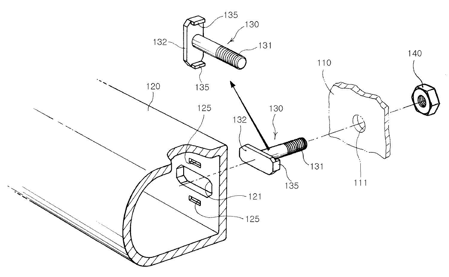
도 2는 방호 울타리를 구성하는 폐단면 보와 그 체결구조를 도시한 사시도이고, 도 3은 폐단면 보에 채결부재가 체결된 상태를 도시한 단면도이다.Figure 2 is a perspective view showing a closed cross-section beam constituting the protective fence and its fastening structure, Figure 3 is a cross-sectional view showing a state in which the locking member is fastened to the closed cross-section beam.
도 2 및 도 3을 참조하면, 상기 지주(110)는 양측으로 플랜지가 형성된 'H' 형태로 형성될 수 있다. 상기 지주(110)의 플랜지에는 상기 보(120)가 체결될 위치에 결합홀(111)(도 3 참조)이 형성된다. 이때, 상기 결합홀(111)은 지주(110)의 교량이나 도로 중앙 측에 배치되는 플랜지에 형성될 수 있다.2 and 3, the
상기 보(120)는 단면이 폐쇄된 형태로 형성된다. 예를 들면, 상기 보(120)의 단면은 일면이 라운드된 직사각형 형태로 형성될 수 있다. 또한, 상기 보(120)의 단면은 원형, 타원형 및 다각형 형태 등 다양하게 형성될 수 있다. 물론, 상기 보(120)는 사방이 폐쇄되는 한 불규칙한 형태로 형성될 수도 있다. The
상기 보(120)의 일면에는 상기 장공 형태의 체결홀(121)이 직접 형성될 수 있다. 이때, 상기 체결홀(121)은 직사각형 형태 또는 삼각형 형태로 형성될 수도 있다. 이러한 체결홀(121)은 중심에서 원주까지의 반경이 다른 여러 형태로 형성될 수 있다.The
상기 보(120)에는 지주(110)의 간격마다 체결홀(121)이 배치된다. 예를 들면, 상기 보(120)가 2개의 지주(110)에 연결되는 경우, 상기 체결홀(121)은 상기 지주(110)의 양끝단부에 각각 배치될 것이다. 또한, 상기 보(120)가 3개의 지주(110)에 연결되는 경우, 상기 체결홀(121)은 상기 지주(110)의 끝단부와 중심부에 각각 배치될 것이다.Fastening
또한, 상기 보(120)의 체결홀(121) 주위에는 후술할 스토퍼(135)가 끼워지도록 스토퍼(135)의 형상에 대응되게 구속홈(125)이 천공 형성될 수 있다. 예를 들면, 상기 구속홈(125)은 체결홀(121)의 단축 방향 양측 또는 일측에 형성될 수 있다.In addition, around the
상기 체결홀(121)에는 체결부재(130)가 삽입된다. 이때, 상기 체결부재(130)는 나사선이 형성된 몸체(131)와, 상기 몸체(131)의 일단부에 일체로 형성되어 상기 체결홀(121)에 삽입되는 헤드(132)를 포함한다.The
상기 체결부재(130)의 헤드(132)는 체결홀(121)에 삽입된 후 소정 각도 회전되면 상기 체결홀(121)의 주위에 걸려 상기 헤드(132)가 체결홀(121)에서 빠지지 않도록 길이와 폭이 다른 형태로 형성된다. 예를 들면, 상기 헤드(132)는 직사각형 형태로 형성될 수 있다. 또한, 상기 헤드(132)는 상기 몸체(131)의 중심에서 반경이 다른 형태로 형성될 수 있다. 또한, 상기 헤드(132)는 상기 체결홀(121)과 대응되는 형상으로 형성될 수 있다.When the
또한, 체결부재(130)에는 체결부재(130)가 체결홀(121)에 삽입된 후 회전될 때에 폐단면 보(120)의 판면으로 삽입되어 맞물려 걸리도록 스토퍼(135)가 형성된다. 즉, 상기 헤드(132)의 양단부에는 상기 구속홈(125)에 삽입되어 구속될 수 있도록 스토퍼(135)가 형성된다. 상기 스토퍼(135)가 구속홈(125)에 삽입되면, 상기 체결부재(130)는 회전되지 않고 구속된다.In addition, the
상기 체결부재(130)의 몸체(131)의 나사선에는 결합부재(140)가 나사결합된다. 이러한 결합부재(140)로는 너트를 적용할 수 있다. 이에, 체결부재(130)의 헤드(132)는 체결부재(130)가 폐단면 보(120), 지주(110) 및 결합부재(140)에 결합된 후 폐단면 보(120)의 내부에 배치되어 폐단면 보(120)의 외부로 노출되지 않는다.
이와 같이 구성된 본 발명에 따른 방호 울타리의 설치 과정에 관해 설명하기로 한다.The installation process of the protective fence according to the present invention configured as described above will be described.
도 4는 폐단면 보의 체결홀에 상기 체결부재가 완전히 삽입되기 이전의 상태를 도시한 배면도이고, 도 5는 폐단면 보의 체결홀에 상기 체결부재가 완전히 삽입되어 스토퍼가 구속홈에 삽입된 상태를 도시한 배면도이다.4 is a rear view showing a state before the fastening member is completely inserted into the fastening hole of the closed end beam, Figure 5 is the fastening member is completely inserted into the fastening hole of the closed end beam so that the stopper is inserted into the restraint groove. It is a rear view which shows the state which became.
도 4를 참조하면, 상기 폐단면 보(120)의 체결홀(121)에 상기 체결부재(130)의 헤드(132)를 삽입한다. 이때, 상기 헤드(132)의 장방향과 상기 체결홀(121)의 장방향이 일치되도록 상기 체결부재(130)가 회전된다.Referring to FIG. 4, the
도 5를 참조하면, 상기 폐단면 보(120)의 체결홀(121)에 상기 체결부재(130)의 헤드(132)가 삽입된 후 상기 체결부재(130)를 대략 90도 회전시킨다. 이때, 상기 헤드(132)의 스토퍼(135)는 상기 폐단면 보(120)의 구속홈(125)에 대응된다.Referring to FIG. 5, after the
그리고, 상기 지주(110)들에 폐단면 보(120)를 대응시킨 후 상기 체결부재(130)의 몸체(131)를 상기 지주(110)의 결합홀(111)에 삽입한다. 이때, 상기 체결부재(130)의 몸체(131)에 결합부재(140)를 체결한다. Then, after the closed
이때, 상기 헤드(132)의 스토퍼(135)가 상기 폐단면 보(120)의 구속홈(125)에 삽입되면, 상기 체결부재(130)는 회전되지 않도록 구속된다. 이렇게 상기 폐단면 보(120)가 체결부재(130)에 의해 지주(110)에 결합되므로, 상기 폐단면 보(120)의 인장 저항력을 향상시키고 체결력을 향상시킬 수 있다. In this case, when the
본 발명은 폐단면 보를 체결부재에 의해 지주에 결합시키고, 인장 저향력과 체결력을 향상시킬 수 있으므로, 산업상으로 현저한 이용 가능성이 있다.In the present invention, the closed cross-section beam can be coupled to the support by the fastening member, and thus the tensile strength and the fastening force can be improved.
도 1은 본 발명에 따른 방호 울타리를 도시한 사시도이다.1 is a perspective view showing a protective fence according to the present invention.
도 2는 도 1의 방호 울타리를 구성하는 폐단면 보와 그 체결구조를 도시한 사시도이다.2 is a perspective view illustrating a closed cross-sectional beam and a fastening structure constituting the protective fence of FIG.
도 3은 도 2의 폐단면 보에 채결부재가 체결된 상태를 도시한 단면도이다.3 is a cross-sectional view showing a state in which a locking member is fastened to the closed cross-sectional beam of FIG.
도 4는 도 3의 폐단면 보의 체결홀에 상기 체결부재가 완전히 삽입되기 이전의 상태를 도시한 배면도이다.4 is a rear view illustrating a state before the fastening member is completely inserted into the fastening hole of the closed cross-sectional beam of FIG. 3.
도 5는 도 3의 폐단면 보의 체결홀에 상기 체결부재가 완전히 삽입되어 스토퍼가 구속홈에 삽입된 상태를 도시한 배면도이다.5 is a rear view illustrating a state in which the fastening member is completely inserted into the fastening hole of the closed end beam of FIG.
Claims (4)
Priority Applications (1)
| Application Number | Priority Date | Filing Date | Title |
|---|---|---|---|
| KR1020070135879A KR100942674B1 (en) | 2007-12-21 | 2007-12-21 | Safety barrier |
Applications Claiming Priority (1)
| Application Number | Priority Date | Filing Date | Title |
|---|---|---|---|
| KR1020070135879A KR100942674B1 (en) | 2007-12-21 | 2007-12-21 | Safety barrier |
Publications (2)
| Publication Number | Publication Date |
|---|---|
| KR20090068025A KR20090068025A (en) | 2009-06-25 |
| KR100942674B1 true KR100942674B1 (en) | 2010-02-17 |
Family
ID=40995681
Family Applications (1)
| Application Number | Title | Priority Date | Filing Date |
|---|---|---|---|
| KR1020070135879A KR100942674B1 (en) | 2007-12-21 | 2007-12-21 | Safety barrier |
Country Status (1)
| Country | Link |
|---|---|
| KR (1) | KR100942674B1 (en) |
Families Citing this family (2)
| Publication number | Priority date | Publication date | Assignee | Title |
|---|---|---|---|---|
| KR101902219B1 (en) * | 2012-06-26 | 2018-10-01 | 한온시스템 주식회사 | Carrier for vehicle |
| NO20180569A1 (en) * | 2018-04-24 | 2019-07-22 | Vik Oersta As | Fastening device and stabilizing device for providing a female connection unit in a wall of an element and system and method for fastening elements together |
Citations (4)
| Publication number | Priority date | Publication date | Assignee | Title |
|---|---|---|---|---|
| JPS5738912U (en) | 1980-08-18 | 1982-03-02 | ||
| JPS61103619U (en) | 1984-12-12 | 1986-07-01 | ||
| KR20010003621A (en) * | 1999-06-24 | 2001-01-15 | 이구택 | Steel guide rail and impact absorber used for the same guide rail |
| KR200428432Y1 (en) * | 2006-07-14 | 2006-10-11 | 이종현 | Combination structure of pillar for fence |
-
2007
- 2007-12-21 KR KR1020070135879A patent/KR100942674B1/en not_active IP Right Cessation
Patent Citations (4)
| Publication number | Priority date | Publication date | Assignee | Title |
|---|---|---|---|---|
| JPS5738912U (en) | 1980-08-18 | 1982-03-02 | ||
| JPS61103619U (en) | 1984-12-12 | 1986-07-01 | ||
| KR20010003621A (en) * | 1999-06-24 | 2001-01-15 | 이구택 | Steel guide rail and impact absorber used for the same guide rail |
| KR200428432Y1 (en) * | 2006-07-14 | 2006-10-11 | 이종현 | Combination structure of pillar for fence |
Also Published As
| Publication number | Publication date |
|---|---|
| KR20090068025A (en) | 2009-06-25 |
Similar Documents
| Publication | Publication Date | Title |
|---|---|---|
| US7794173B2 (en) | Deformable divider for a vehicle impact safety barrier, of the type that is used between a vertical support-or post-fixing element and a horizontal impact or railing element | |
| US6398192B1 (en) | Breakaway support post for highway guardrail end treatments | |
| CA2474268C (en) | Cable guardrail release system | |
| ES2255159T3 (en) | BREAK SUPPORT POST FOR EXTREME TREATMENTS OF GUARDARRAIL DE CARRETERA. | |
| US11629524B2 (en) | Collar for installation of barriers onto existing bollards | |
| US8915486B2 (en) | Releaseable anchor cables for cable barriers that release upon certain load conditions upon the cable barrier | |
| KR100723027B1 (en) | A guard rail | |
| KR100942674B1 (en) | Safety barrier | |
| KR101473818B1 (en) | Shock absorbing t Vehicle protection fence | |
| KR102185578B1 (en) | Guard rail reinforcement structure for shock absorption and climb-over prevention | |
| KR200383560Y1 (en) | A guard rail provide with safety sock-absorber device | |
| KR102123084B1 (en) | Guard fence having function of shock absorption and sidewalk intrusion prevention | |
| KR200287841Y1 (en) | The saftty barrier which have a wire rope within guard pipe | |
| KR101001199B1 (en) | Safety barrier comprised of hybrid material | |
| KR100605272B1 (en) | Safety barrier with wire rope coupling device | |
| KR200336614Y1 (en) | Guardrail structure for road | |
| KR20120092082A (en) | Guardrails for absorption of impact | |
| KR102194393B1 (en) | Multi elastic bollard | |
| KR200283319Y1 (en) | Height limit structure of suspension type for the prevention of construction of under-road enterance | |
| KR200201066Y1 (en) | Reinforced fence | |
| KR20160027703A (en) | Guard rail having circular bumpers | |
| CA2583043C (en) | Breakaway support post for highway guardrail end treatments | |
| KR20170021720A (en) | Vehicle guard fence for bridge | |
| KR20090068027A (en) | Safety barrier | |
| AU2003214967A1 (en) | Cable guardrail release system |
Legal Events
| Date | Code | Title | Description |
|---|---|---|---|
| A201 | Request for examination | ||
| E902 | Notification of reason for refusal | ||
| E701 | Decision to grant or registration of patent right | ||
| GRNT | Written decision to grant | ||
| FPAY | Annual fee payment |
Payment date: 20130115 Year of fee payment: 4 |
|
| LAPS | Lapse due to unpaid annual fee |