KR20190110155A - Discharge lamp - Google Patents
Discharge lamp Download PDFInfo
- Publication number
- KR20190110155A KR20190110155A KR1020197027510A KR20197027510A KR20190110155A KR 20190110155 A KR20190110155 A KR 20190110155A KR 1020197027510 A KR1020197027510 A KR 1020197027510A KR 20197027510 A KR20197027510 A KR 20197027510A KR 20190110155 A KR20190110155 A KR 20190110155A
- Authority
- KR
- South Korea
- Prior art keywords
- discharge lamp
- base
- shaft portion
- predetermined direction
- base member
- Prior art date
Links
Images


Classifications
-
- F—MECHANICAL ENGINEERING; LIGHTING; HEATING; WEAPONS; BLASTING
- F21—LIGHTING
- F21V—FUNCTIONAL FEATURES OR DETAILS OF LIGHTING DEVICES OR SYSTEMS THEREOF; STRUCTURAL COMBINATIONS OF LIGHTING DEVICES WITH OTHER ARTICLES, NOT OTHERWISE PROVIDED FOR
- F21V19/00—Fastening of light sources or lamp holders
- F21V19/006—Fastening of light sources or lamp holders of point-like light sources, e.g. incandescent or halogen lamps, with screw-threaded or bayonet base
-
- G—PHYSICS
- G03—PHOTOGRAPHY; CINEMATOGRAPHY; ANALOGOUS TECHNIQUES USING WAVES OTHER THAN OPTICAL WAVES; ELECTROGRAPHY; HOLOGRAPHY
- G03F—PHOTOMECHANICAL PRODUCTION OF TEXTURED OR PATTERNED SURFACES, e.g. FOR PRINTING, FOR PROCESSING OF SEMICONDUCTOR DEVICES; MATERIALS THEREFOR; ORIGINALS THEREFOR; APPARATUS SPECIALLY ADAPTED THEREFOR
- G03F7/00—Photomechanical, e.g. photolithographic, production of textured or patterned surfaces, e.g. printing surfaces; Materials therefor, e.g. comprising photoresists; Apparatus specially adapted therefor
- G03F7/70—Microphotolithographic exposure; Apparatus therefor
- G03F7/70008—Production of exposure light, i.e. light sources
- G03F7/70016—Production of exposure light, i.e. light sources by discharge lamps
-
- G—PHYSICS
- G03—PHOTOGRAPHY; CINEMATOGRAPHY; ANALOGOUS TECHNIQUES USING WAVES OTHER THAN OPTICAL WAVES; ELECTROGRAPHY; HOLOGRAPHY
- G03F—PHOTOMECHANICAL PRODUCTION OF TEXTURED OR PATTERNED SURFACES, e.g. FOR PRINTING, FOR PROCESSING OF SEMICONDUCTOR DEVICES; MATERIALS THEREFOR; ORIGINALS THEREFOR; APPARATUS SPECIALLY ADAPTED THEREFOR
- G03F7/00—Photomechanical, e.g. photolithographic, production of textured or patterned surfaces, e.g. printing surfaces; Materials therefor, e.g. comprising photoresists; Apparatus specially adapted therefor
- G03F7/70—Microphotolithographic exposure; Apparatus therefor
- G03F7/708—Construction of apparatus, e.g. environment aspects, hygiene aspects or materials
- G03F7/70808—Construction details, e.g. housing, load-lock, seals or windows for passing light in or out of apparatus
- G03F7/70833—Mounting of optical systems, e.g. mounting of illumination system, projection system or stage systems on base-plate or ground
-
- H—ELECTRICITY
- H01—ELECTRIC ELEMENTS
- H01J—ELECTRIC DISCHARGE TUBES OR DISCHARGE LAMPS
- H01J5/00—Details relating to vessels or to leading-in conductors common to two or more basic types of discharge tubes or lamps
- H01J5/50—Means forming part of the tube or lamps for the purpose of providing electrical connection to it
- H01J5/54—Means forming part of the tube or lamps for the purpose of providing electrical connection to it supported by a separate part, e.g. base
- H01J5/56—Shape of the separate part
-
- H—ELECTRICITY
- H01—ELECTRIC ELEMENTS
- H01J—ELECTRIC DISCHARGE TUBES OR DISCHARGE LAMPS
- H01J61/00—Gas-discharge or vapour-discharge lamps
- H01J61/02—Details
- H01J61/52—Cooling arrangements; Heating arrangements; Means for circulating gas or vapour within the discharge space
- H01J61/523—Heating or cooling particular parts of the lamp
-
- H—ELECTRICITY
- H01—ELECTRIC ELEMENTS
- H01J—ELECTRIC DISCHARGE TUBES OR DISCHARGE LAMPS
- H01J61/00—Gas-discharge or vapour-discharge lamps
- H01J61/82—Lamps with high-pressure unconstricted discharge having a cold pressure > 400 Torr
- H01J61/822—High-pressure mercury lamps
Landscapes
- Physics & Mathematics (AREA)
- Engineering & Computer Science (AREA)
- General Physics & Mathematics (AREA)
- Plasma & Fusion (AREA)
- General Engineering & Computer Science (AREA)
- Epidemiology (AREA)
- Public Health (AREA)
- Environmental & Geological Engineering (AREA)
- Health & Medical Sciences (AREA)
- Common Detailed Techniques For Electron Tubes Or Discharge Tubes (AREA)
- Exposure And Positioning Against Photoresist Photosensitive Materials (AREA)
- Discharge Lamps And Accessories Thereof (AREA)
- Non-Portable Lighting Devices Or Systems Thereof (AREA)
- Arrangement Of Elements, Cooling, Sealing, Or The Like Of Lighting Devices (AREA)
- Exposure Of Semiconductors, Excluding Electron Or Ion Beam Exposure (AREA)
- Fastening Of Light Sources Or Lamp Holders (AREA)
Abstract
소정 방향으로 대향하여 배치된 양극과 음극을 가지고, 광을 발광시키는 발광부를 덮는 유리 부재와, 유리 부재의 소정 방향의 일방의 측에 마련되는 제1 베이스 부재와, 유리 부재의 소정 방향의 타방의 측에 마련되는 제2 베이스 부재를 구비하는 방전 램프로서, 제1 베이스 부재는, 소정 방향으로 연장하는 축부분과, 축부분의 적어도 유리 부재측과는 반대측의 단부를 덮는 커버부를 가지며, 커버부는, 기체를 유입시키는 유통공을 가지고, 유통공으로부터 유입되는 기체를, 축부분과 커버부와의 사이에, 소정 방향의 타방의 측으로 흐르게 하는 유로를 형성함과 아울러, 축부분과의 사이에, 유로를 흐른 기체를 배기하는 틈새를 형성한다.A glass member having an anode and a cathode disposed in a predetermined direction and covering a light emitting portion for emitting light, a first base member provided on one side of the glass member in a predetermined direction, and the other of the glass member in a predetermined direction; A discharge lamp having a second base member provided on the side, wherein the first base member has a shaft portion extending in a predetermined direction, and a cover portion covering an end portion on the side opposite to at least the glass member side of the shaft portion, and the cover portion And a flow passage through which gas flows in, and a gas flowing from the flow hole flows between the shaft portion and the cover portion to the other side in a predetermined direction, and between the shaft portion, A gap is formed to exhaust the gas flowing through the flow path.
Description
본 발명은 방전램프, 이 방전램프를 구비한 광원장치, 이 광원장치를 구비한 노광장치 및 이 노광장치의 제조방법에 관한 것이다.The present invention relates to a discharge lamp, a light source device having the discharge lamp, an exposure device having the light source device, and a manufacturing method of the exposure device.
각종 디바이스(마이크로 디바이스, 전자 디바이스 등)를 제조하기 위한 리소그래피(lithography) 공정에 있어서는 래티클(reticle)(또는 포토마스크(photomask) 등)에 형성된 패턴을 레지스터(resister)가 도포된 웨이퍼(또는 유리 플레이트 등) 위에 전사(轉寫)하기 위해서, 스텝퍼 등의 일괄노광형(정지(靜止)노광형)의 투영노광장치 및 스캐닝·스텝퍼 등의 주사(走査)노광형의 투영노광장치 등의 노광장치가 사용되고 있다. 이러한 노광장치에 있어서는 종래부터 수은램프 등의 방전램프와 집광거울을 조합시켜 구성되는 노광용 광원장치가 사용되고 있고, 그 방전램프는 소정의 부착기구를 통하여 유지되고 있었다.In the lithography process for manufacturing various devices (micro devices, electronic devices, etc.), a wafer (or glass) coated with a resist is formed on a pattern formed on a reticle (or photomask, etc.). In order to transfer onto a plate, etc., exposure apparatuses, such as a batch exposure type (stop exposure type) projection exposure apparatus, such as a stepper, and scanning exposure type projection exposure apparatuses, such as a scanning stepper, are used. . In such an exposure apparatus, an exposure light source apparatus constructed by combining a discharge lamp such as a mercury lamp and a condensing mirror has conventionally been used, and the discharge lamp has been held through a predetermined attachment mechanism.
종래의 방전램프의 부착기구의 일례는 방전램프의 베이스(base)에 플랜지부 및 링모양의 홈부를 형성해 두고, 그 홈부에 판스프링의 개구부를 걸어 맞추며, 그 판스프링으로 그 플랜지부를 브래킷에 밀어 붙여 고정하는 기구이다(예를 들면, 특허문헌 1 참조). 이 기구에서는 방전램프의 장착시 또는 교환시에는 그 판스프링의 클램프기구를 느슨하게 하여, 그 판스프링의 개구부를 그 베이스가 통과할 수 있도록 그 판스프링을 슬라이드시킬 필요가 있다. 또, 종래의 방전램프의 부착기구의 다른 예는 방전램프의 베이스에 위치결정핀 등을 설치해 두고, 그 베이스를 평판모양의 부착판에 형성된 원형의 개구부에 소정의 회전각으로 찔러 넣어, 그 개구부에 형성한 슬로팅(slotting)부를 볼트로 체결함으로써, 그 베이스를 고정하는 기구이다(예를 들면, 특허문헌 2 참조).An example of a conventional discharge lamp attachment mechanism is to form a flange portion and a ring-shaped groove portion in the base of the discharge lamp, to engage the opening of the leaf spring in the groove portion, and the flange portion to the bracket by the leaf spring It is a mechanism which pushes in and fixes it (for example, refer patent document 1). In this mechanism, when the discharge lamp is mounted or replaced, it is necessary to loosen the clamp mechanism of the leaf spring and slide the leaf spring so that the base can pass through the opening of the leaf spring. In another example of the conventional lamp attachment mechanism, a positioning pin or the like is provided at the base of the discharge lamp, and the base is inserted into a circular opening formed on a flat plate-like mounting plate at a predetermined rotational angle. It is a mechanism which fixes the base by fastening the slotting part formed in this with the bolt (for example, refer patent document 2).
또, 방전램프를 가지는 종래의 광원장치 중에는 발열의 영향을 경감하기 위해서 냉각기구를 구비한 타입도 있다. 종래의 냉각기구의 일례는 방전램프의 한쪽 베이스의 외면(外面)으로부터 밸브부의 외면을 거쳐 다른 쪽 베이스의 외면을 향해서 냉각된 공기를 공급하는 기구이다(예를 들면, 특허문헌 3 참조). 종래의 냉각기구의 다른 예로서, 방전램프의 베이스에 링모양의 홈부를 형성하고, 그 홈부 및 소정의 송풍관을 통하여 밸브관에 냉각된 공기를 공급하는 기구도 알려져 있다(예를 들면, 특허문헌 4참조).In addition, some conventional light source devices having a discharge lamp are provided with a cooling mechanism in order to reduce the effects of heat generation. One example of a conventional cooling mechanism is a mechanism for supplying cooled air from an outer surface of one base of a discharge lamp to an outer surface of the other base via an outer surface of a valve portion (see
종래의 광원장치에 있어서의 방전램프의 부착기구는 방전램프의 장착시 또는 교환시에 판스프링의 클램프기구를 느슨하게 하여 그 판스프링을 슬라이드시키거나, 또는 부착판의 슬로팅부의 클램프를 느슨하게 할 필요가 있기 때문에, 방전램프의 장착 등에 시간을 필요로 한다는 문제가 있었다. 또, 종래의 부착기구는 판스프링에 형성한 개구부의 윤곽 일부를 베이스의 홈부에 걸거나, 또는 부착판의 슬로팅부를 조이거나 하여, 방전램프의 베이스를 고정하고 있기 때문에, 그 베이스를 고정하는 힘을 목표로 하는 범위 내로 설정하는 것이 곤란하다는 문제가 있었다.In the conventional light source device, the discharging lamp attachment mechanism needs to loosen the leaf spring clamp mechanism when the discharge lamp is mounted or replaced, and slide the leaf spring, or loosen the clamp of the slotting part of the mounting plate. There is a problem that it takes time for the discharge lamp to be mounted. In addition, in the conventional attachment mechanism, the base of the discharge lamp is fixed by hooking a part of the contour of the opening formed in the leaf spring to the groove of the base or by tightening the slotting part of the attachment plate. There has been a problem that it is difficult to set the force within a target range.
또, 종래의 광원장치에 있어서의 방전램프의 냉각기구는 주로 방전램프의 밸브부에 냉풍을 내뿜고 있기 때문에, 베이스에 대한 냉각작용이 작다는 문제가 있었다.Moreover, since the cooling mechanism of the discharge lamp in the conventional light source device mainly blows out cold air in the valve part of a discharge lamp, there exists a problem that the cooling effect with respect to a base is small.
본 발명은 이와 같은 사정을 감안하여, 부착기구에 대한 방전램프의 장착 등을 용이하게 하고, 또한 단시간에 실시할 수 있는 광원장치를 제공하는 것을 제1 목적으로 한다.In view of such circumstances, it is a first object of the present invention to provide a light source device that facilitates the mounting of a discharge lamp to an attachment mechanism and can be implemented in a short time.
또, 본 발명은 간단한 기구로 방전램프의 냉각을 효율적으로 실시할 수 있는 광원장치를 제공하는 것을 제2 목적으로 한다.Another object of the present invention is to provide a light source device capable of efficiently cooling a discharge lamp with a simple mechanism.
또한, 본 발명은 그러한 광원장치에 적용할 수 있는 방전램프 및 그 광원장치를 이용하는 노광기술을 제공하는 것도 목적으로 한다.It is also an object of the present invention to provide a discharge lamp applicable to such a light source device and an exposure technique using the light source device.
본 발명의 제1 형태에 따른 광원장치는 발광부를 형성하는 유리부재(25)와 이 유리부재에 연결된 베이스부재(26)를 가지는 방전램프(1)와, 그 베이스부재를 통하여 그 방전램프를 유지하는 유지부재(50, 52)를 가지는 유지장치(31)를 구비한 광원장치로서, 그 방전램프가 구비하는 그 베이스부재는 유지부재와 맞닿아 그 유지부재에 대한 그 발광부의 제1 방향에서의 위치를 규정하는 맞닿음부(26a)와, 그 맞닿음부를 그 제1 방향을 따라서 그 유지부재로 가압하는 가압력이 밀어 붙여지는 피가압부(26e ~ 26h)와, 그 맞닿음부와 그 피가압부와의 사이에 구비되어 그 유지부재와 끼워맞춤하는 끼워맞춤부(26b)와, 그 끼워맞춤부에 구비되어 그 맞닿음부 근방으로부터 그 피가압부에 이르는 냉각용 매체의 유로를 그 유지부재와의 사이에 구성하는 홈부(26d)를 가지고, 그 유지장치는 그 유지부재와, 그 피가압부에 그 가압력을 가하는 가압부재(55A)와, 그 가압부재에 의한 그 맞닿음부의 그 유지부재로의 가압과, 이 가압의 해제를 전환하는 전환기구(63)와, 그 베이스부재를 냉각하기 위한 매체를 그 홈부를 통하여 그 유로에 공급하는 매체공급장치(71)를 가지는 것이다.A light source device according to the first aspect of the present invention is a discharge lamp (1) having a glass member (25) forming a light emitting portion and a base member (26) connected to the glass member, and holding the discharge lamp through the base member. A light source device having a
또, 본 발명의 제2 형태에 따른 광원장치는 발광부를 형성하는 유리부재(25)와, 이 유리부재에 연결된 베이스부재(26)를 가지는 방전램프(1)와, 그 베이스부재를 통하여 그 방전램프를 유지하는 유지부재(50, 52)를 가지는 유지장치(31)를 구비한 광원장치로서, 그 방전램프가 구비하는 그 베이스부재는 그 유지부재와 맞닿아 그 유지부재에 대한 그 발광부의 제1 방향에서의 위치를 규정하는 맞닿음부(26a)와, 그 맞닿음부를 그 제1 방향을 따라서 그 유지부재로 가압하는 가압력이 밀어 붙여지는 피가압부(26e ~ 26h)와, 그 맞닿음부와 그 피가압부와의 사이에 구비되어 그 유지부재에 대해 그 발광부의 제1 방향과 직교하는 방향에서의 위치를 규정하는 규정부(26b1)와, 그 맞닿음부와 피가압부와의 사이에 구비되어 맞닿음부 근방으로부터 피가압부에 이르는 냉각용 매체의 유로를 그 유지부재와의 사이에 구성하는 냉각부(26b2)를 가지고, 그 유지장치는 그 유지부재와, 그 피가압부에 그 가압력을 가압하는 가압부재(55A)와, 그 가압부재에 의한 그 맞닿음부의 그 유지부재로의 가압과, 이 가압의 해제를 전환하는 전환기구(63)와, 그 베이스부재를 냉각하기 위한 매체를 그 유로에 공급하는 매체공급장치(71)를 가지는 것이다.Further, the light source device according to the second aspect of the present invention is a
다음에, 본 발명의 제1 형태에 따른 방전램프는 발광부를 형성하는 유리부재(25)와, 이 유리부재에 연결된 베이스부재(26)를 구비한 방전램프(1)로서, 그 방전램프는 이 방전램프와는 별개로 설치된 유지부재(50, 52)에 그 베이스부재를 통하여 착탈가능하게 유지되고, 그 베이스부재는 그 유지부재와 맞닿아 그 유지부재에 대한 그 발광부의 제1 방향에서의 위치를 규정하는 맞닿음부(26a)와, 그 맞닿음부를 그 제1 방향을 따라서 그 유지부재로 가압하는 가압력이 밀어 붙여지는 피가압부(26e ~ 26h)와, 그 맞닿음부와 그 피가압부와의 사이에 구비되어 그 유지부재와 끼워맞춤하는 끼워맞춤부(26b)와, 그 끼워맞춤부에 구비되어 그 맞닿음부 근방으로부터 그 피가압부에 이르는 냉각용 매체의 유로를 그 유지부재와의 사이에 구성하는 홈부(26d)를 가지는 것이다.Next, the discharge lamp according to the first aspect of the present invention is a
또, 본 발명의 제2 형태에 따른 방전램프는 발광부를 형성하는 유리부재(25)와, 이 유리부재에 연결된 제1 베이스부재(26)와, 그 제1 베이스부재와는 다른 위치에서 그 유리부재에 연결된 제2 베이스부재(28)를 구비한 방전램프로서, 그 방전램프는 이 방전램프와는 별개로 설치된 유지부재(50, 52)에 그 제1 베이스부재를 통하여 착탈가능하게 유지되고, 그 제1 베이스부재는 그 유지부재와 맞닿아 그 유지부재에 대한 그 발광부의 제1 방향에서의 위치를 규정하는 맞닿음부(26a)와, 그 맞닿음부에 대해서 그 유리부재와는 그 제1 방향을 따른 반대 측에 구비되어 그 유지부재와 끼워맞춤하는 끼워맞춤부(26b)와, 그 끼워맞춤부에 구비되어 냉각용 매체의 유로를 그 유지부재와의 사이에 구성하는 홈부(26d)를 구비하고, 그 제2 베이스부재는 그 제2 베이스부재를 냉각하는 냉각용 매체가 유통되는 유로(28f)를 구비하는 것이다.Further, the discharge lamp according to the second aspect of the present invention has a
또, 본 발명의 제3 형태에 따른 방전램프는 서로 이간한 제1 및 제2 전극 사이에 방전하는 것에 의해 발광하는 방전램프(1)로서, 그 제1 전극과 접속된 제1 베이스부재(26)와, 그 제2 전극과 접속된 제2 베이스부재(28)를 구비하고, 그 제1 베이스부재에는 그 제1 베이스부재를 냉각하는 냉각매체가 유동하는 제1 유로(26d)가 형성되며, 그 제2 베이스부재에는 그 제2 베이스부재를 냉각하는 냉각매체가 유동하는 제2 유로(28f)가 형성되어 있는 것이다.The discharge lamp according to the third aspect of the present invention is a
또, 본 발명의 제4 형태에 따른 방전램프는 발광부를 형성하는 유리부재(25)와, 이 유리부재의 제1 방향 측에 연결되고, 그 제1 방향과 직교하는 제2 방향으로 연장해 있는 맞닿음부(26a)와, 그 제1 방향을 따른 힘이 밀어 붙여지는 피가압부(26e ~ 26h)와, 그 맞닿음부와 그 피가압부와의 사이에 구비된 끼워맞춤부(26b)와, 그 끼워맞춤부에 구비된 홈부(26d)를 가지는 베이스부재(26)를 구비하고, 그 베이스부재는 그 피가압부로 밀어 붙여진 그 제1 방향의 힘에 의해 그 맞닿음부와 맞닿아 그 발광부의 그 제1 방향의 위치를 규정함과 동시에 그 끼워맞춤부와 끼워맞춤하는 것에 의해 그 제1 방향과 직교하는 방향의 위치를 규정하고, 또한 그 유지부재와 그 홈부와의 사이에 형성된 유로에 냉각용 매체를 공급하는 유지장치(31)에 유지가능한 것이다.In addition, the discharge lamp according to the fourth aspect of the present invention includes a
다음에, 본 발명의 제5 형태에 따른 방전램프는 발광부를 형성하는 유리부재(25a)와, 이 유리부재에 연결된 베이스부재(26P)를 구비한 방전램프(1P)로서, 그 방전램프는 이 방전램프와는 별개로 설치된 유지부재(50, 52)에 그 베이스부재를 통하여 착탈가능하게 유지되고, 그 베이스부재는 그 유지부재와 맞닿아 그 유지부재에 대한 그 발광부의 제1 방향에서의 위치를 규정하는 맞닿음부(26a)와, 그 맞닿음부를 그 제1 방향을 따라서 그 유지부재로 가압하는 가압력이 밀어 붙여지는 피가압부(26e ~ 26h)와, 그 맞닿음부와 그 피가압부와의 사이에 구비되어 그 유지부재와 끼워맞춤하는 끼워맞춤부(26b)와, 그 끼워맞춤부의 내부를 통과하도록 그 맞닿음부 근방과 그 피가압부와의 사이에 구비된 냉각용 매체의 유로가 되는 유체로(26pd)를 가지는 것이다.Next, the discharge lamp according to the fifth aspect of the present invention is a
또, 본 발명의 제3 형태에 따른 광원장치는 본 발명의 제5 형태에 따른 방전램프와, 그 베이스부재를 통하여 그 방전램프를 유지하는 그 유지부재를 가지는 유지장치(31)를 구비한 광원장치로서, 그 유지장치는 그 피가압부에 그 가압력을 밀어 붙이는 가압부재와, 그 베이스부재를 냉각하기 위한 매체를 그 유체로에 공급하는 매체공급장치(71)를 가지는 것이다.A light source device according to a third aspect of the present invention further includes a light source having a discharge lamp according to the fifth aspect of the present invention and a
또, 본 발명의 제6 형태에 따른 방전램프는 발광부를 형성하는 유리부재(25 ; 25A)와, 이 유리부재에 연결된 베이스부재(26 ; 26P)를 구비한 방전램프로서, 그 베이스부재는 제1 방향에 평행한 제1 축을 따라서 유리부재로부터 멀어지는 방향으로, 차례대로, 그 제1 축을 중심으로 하는 제1 반경 이상의 반경을 가지는 원반형상을 포함하는 형상을 가지는 맞닿음부(26a)와, 그 제1 축을 중심으로 하는 그 제1 반경보다 작은 제2 반경을 가지는 원기둥형상에 외접(外接)하는 형상을 가지는 끼워맞춤부(26b)와, 그 제1 축을 중심으로 하여 그 제2 반경보다 작은 제3 반경을 가지는 원기둥형상을 포함하는 형상을 가지는 소경부(小徑部)(26k)와, 그 제1 축을 중심으로 하여 그 제1 반경보다 작고 또한 그 제3 반경보다 큰 제4 반경을 가지는 원반형상을 포함하는 형상을 가지는 피가압부(26g, 26h)를 가짐과 동시에, 그 끼워맞춤부의 외주 또는 그 근방에 그 끼워맞춤부와 공기와의 접촉면적을 증대시키기 위한 입체구조(26d ; 26Pd)를 가지는 것이다.Further, the discharge lamp according to the sixth aspect of the present invention is a discharge lamp having a glass member (25; 25A) for forming a light emitting portion and a base member (26; 26P) connected to the glass member, wherein the base member is made of Abutting
또, 본 발명의 제7 형태에 따른 방전램프는 발광부를 구비하고, 제1 방향으로 늘어나도록 형성된 유리부재(25 ; 25A)와, 그 유리부재의 그 제1 방향 측의 단부에 일단부가 연결되는 제1 베이스부재(26 ; 26P)를 구비한 방전램프로서, 그 제1 베이스부재는 그 제1 방향과 직교하는 직교방향으로 돌출한 돌출부(26a)와, 그 돌출부와 그 제1 베이스부재의 타단부와의 사이에 형성되고, 그 직교방향에 관한 외형형상이 그 돌출부의 외형형상보다 작은 제1 축부(26b)와, 그 돌출부와 그 제1 베이스부재의 타단부와의 사이에 형성되고, 그 직교방향에 관한 외형형상이 그 제1 축부보다 작은 제2 축부(26k)와, 그 돌출부와 그 제1 베이스부재의 타단부와의 사이에 형성되고, 그 직교방향에 관한 외형형상이 그 돌출부의 외형형상보다 작고 또한 그 제2 축부보다 큰 제3 축부(26g ; 26h)와, 그 제1 축부의 외주면의 적어도 일부에 형성되고, 냉각용 매체와 접촉가능한 냉각부(26b2)를 구비하는 것이다.Further, the discharge lamp according to the seventh aspect of the present invention includes a light emitting portion, one end of which is connected to the glass member 25 (25A) formed to extend in the first direction and an end portion of the glass member in the first direction side thereof. A discharge lamp having a first base member (26; 26P), the first base member having a protrusion (26a) projecting in a direction orthogonal to the first direction, and the other part of the protrusion and the first base member. It is formed between the end part, and the external shape in the orthogonal direction is formed between the
또, 본 발명의 제8 형태에 따른 방전램프는 발광부를 형성하는 유리부재(25)와, 이 유리부재에 연결된 베이스부재(26)를 구비한 방전램프(1)로서, 그 방전램프는 이 방전램프와는 별개로 설치된 유지부재(50, 52)에 그 베이스부재를 통하여 착탈가능하고, 그 베이스부재는 그 유지부재와 맞닿아 그 유지부재에 대한 그 발광부의 제1 방향에서의 위치를 규정하는 맞닿음부(26a)와, 그 맞닿음부를 그 제1 방향을 따라서 그 유지부재에 가압하는 가압력이 밀어 붙여지는 피가압부(26e ~ 26h)와, 그 맞닿음부와 그 피가압부와의 사이에 구비되어 상기 유지부재와 끼워맞춤하는 끼워맞춤부(26b)와, 그 맞닿음부와 그 피가압부와의 사이에 형성되어 그 맞닿음부 근방으로부터 그 피가압부에 이르는 냉각용 매체의 유로를 그 유지부재와의 사이에 구성하는 냉각부를 가지는 것이다.Further, the discharge lamp according to the eighth aspect of the present invention is a discharge lamp (1) having a glass member (25) forming a light emitting portion and a base member (26) connected to the glass member, the discharge lamp having this discharge. Removable through the base member to the
또, 본 발명의 형태에 따른 노광장치는 광원장치로부터 발생한 노광광에 의해서 감광기판에 패턴을 노광하는 노광장치로서, 그 광원장치로서 본 발명의 광원장치(30)를 구비한 것이다.Moreover, the exposure apparatus which concerns on the aspect of this invention is an exposure apparatus which exposes a pattern to a photosensitive board | substrate with the exposure light which generate | occur | produced from the light source apparatus, and is provided with the
또, 본 발명의 형태에 따른 노광장치의 제조방법은 방전램프(1)의 2개의 전극 사이의 방전에 의해 발생한 광에 의해서 감광기판에 패턴을 노광하는 노광장치의 제조방법으로서, 그 방전램프를 유지하기 위한 유지장치(31)에 그 방전램프의 그 2개의 전극 중 한쪽에 대응하여 설치된 제1 베이스부재(26)를 통하여 그 방전램프를 장착하는 단계와, 그 방전램프의 다른 쪽의 전극에 대응하여 설치된 제2 베이스부재(28)에 용력(用力)케이블(33B)을 접속하는 단계와, 그 장착된 그 방전램프의 그 제1 베이스부재를 그 유지장치에 장착된 상태로 냉각하는 단계를 구비하는 것이다.In addition, a method of manufacturing an exposure apparatus according to an aspect of the present invention is a method of manufacturing an exposure apparatus in which a pattern is exposed on a photosensitive substrate by light generated by a discharge between two electrodes of the
또한, 이상의 본 발명의 소정 요소에 병기한 괄호 부호는, 본 발명의 일실시형태를 나타내는 도면 중의 부재에 대응하고 있지만, 각 부호는 본 발명을 알기 쉽게 하기 위해서 본 발명의 요소를 예시하는 것에 지나지 않고, 본 발명을 그 실시형태의 구성으로 한정하는 것은 아니다.In addition, although the parenthesis code written together in the above predetermined element of this invention corresponds to the member in the figure which shows one Embodiment of this invention, each code | symbol is only what illustrates the element of this invention in order to make this invention easy to understand. In addition, this invention is not limited to the structure of the embodiment.
본 발명의 제1, 제2 또는 제3 형태에 따른 광원장치에 의하면, 유지장치에 대한 그 방전램프의 떼어냄 및 장착을 용이하게 단시간에 실시할 수 있다. 또, 간단한 기구로 방전램프의 냉각을 효율적으로 실시할 수 있다.According to the light source device according to the first, second or third aspect of the present invention, the discharge lamp can be detached and attached to the holding device easily and in a short time. In addition, the discharge lamp can be cooled efficiently with a simple mechanism.
또, 본 발명의 방전램프는 본 발명의 제1, 제2 또는 제3 형태에 따른 광원장치의 방전램프로서 사용할 수 있다.The discharge lamp of the present invention can be used as a discharge lamp of a light source device according to the first, second or third aspect of the present invention.
도 1은 본 발명의 실시형태의 일례인 투영노광장치의 개략 구성을 나타내는 도이다.
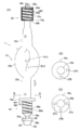
도 2의 (A)는 도 1 중의 방전램프(1)를 나타내는 일부를 절개한 도, (B)는 도 2의 (A)의 BB선에 따른 단면도, (C)는 도 2의 (B)의 다른 구성예를 나타내는 도이다.
도 3은 도 1 중의 부착장치(31)를 나타내는 일부를 절개한 도이다.
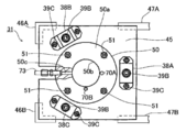
도 4는 도 3의 부착장치(31)의 주요부를 나타내는 평면도이다.
도 5는 도 3의 AA선에 따른 단면도이다.
도 6은 도 3의 BB선에 따라 일부를 생략한 단면도이다.
도 7의 (A)는 도 3 중의 고정용 암(55A)을 위쪽에서 본 확대단면도, (B)는 그 고정용 암(55A)을 확대하여 나타내는 정면도이다.
도 8은 도 2의 (A)의 방전램프(1)를 도 3의 부착장치(31)에 장착한 상태를 나타내는 일부를 절개한 도이다.
도 9는 도 8의 방전램프(1)의 베이스부(26) 및 부착장치(31)의 부분을 확대하여 나타내는 일부를 절개한 도이다.
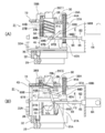
도 10의 (A)는 도 3의 부착장치(31)에 있어서, 전환용 링크기구(63)에 의해서 이동부재(41)를 강하시킨 상태를 나타내는 도, (B)는 전환용 링크기구(63)에 의해서 이동부재(41)를 상승시킨 상태를 나타내는 도이다.
도 11의 (A), (B), (C) 및 (D)는 각각 본 발명의 방전램프의 다른 실시형태를 나타내는 일부를 절개한 도이다.
도 12의 (A), (B), (C) 및 (D)는 각각 본 발명의 방전램프의 또 다른 실시형태를 나타내는 일부를 절개한 도이다.
도 13의 (A), (B) 및 (C)는 각각 본 발명의 방전램프의 또 다른 실시형태를 나타내는 도이다.
도 14의 (A) 및 (B)는 각각 본 발명의 방전램프의 또 다른 실시형태를 나타내는 일부를 절개한 도이다.
도 15의 (A), (B), (C) 및 (D)는 각각 본 발명의 방전램프의 또 다른 실시형태를 나타내는 도이다.
도 16의 (A)는 도 15의 (B)의 AA선에 따른 단면도, (B)는 도 15의 (C)의 BB선에 따른 단면도, (C)는 도 15의 (D)의 CC선에 따른 단면도이다.
도 17은 도 15의 (D)에 나타내는 방전램프의 제조방법의 일례를 나타내는 주요부의 사시도이다.
도 18의 (A) 및 (B)는 각각 본 발명의 방전램프의 또 다른 실시형태를 나타내는 도이다.
도 19는 마이크로 디바이스의 제조공정의 일례를 나타내는 플로우챠트이다.BRIEF DESCRIPTION OF THE DRAWINGS It is a figure which shows schematic structure of the projection exposure apparatus which is an example of embodiment of this invention.
FIG. 2A is a view in which a part of the
3 is a view showing a portion of the
4 is a plan view showing a main part of the
5 is a cross-sectional view taken along line AA of FIG. 3.
FIG. 6 is a cross-sectional view of a portion omitted along the line BB of FIG. 3.
FIG. 7A is an enlarged cross-sectional view of the fixing
FIG. 8 is a partially cutaway view showing a state in which the
FIG. 9 is an enlarged view of a portion of the
FIG. 10A is a view showing a state in which the moving
11 (A), (B), (C) and (D) are cutaway views showing a part of another embodiment of the discharge lamp of the present invention.
12 (A), (B), (C) and (D) are cutaway views showing still another embodiment of the discharge lamp of the present invention, respectively.
13A, 13B, and 13C are diagrams each showing yet another embodiment of the discharge lamp of the present invention.
Figs. 14A and 14B each show a cutaway view of still another embodiment of the discharge lamp of the present invention.
15 (A), (B), (C) and (D) are diagrams showing still another embodiment of the discharge lamp of the present invention, respectively.
(A) is sectional drawing along the AA line of FIG. 15 (B), (B) is sectional drawing along the BB line of FIG. 15 (C), (C) is the CC line of FIG. 15 (D) In accordance with the cross-sectional view.
FIG. 17 is a perspective view of an essential part showing an example of a method of manufacturing the discharge lamp shown in FIG. 15D. FIG.
18A and 18B are diagrams each showing yet another embodiment of the discharge lamp of the present invention.
It is a flowchart which shows an example of the manufacturing process of a microdevice.
이하, 본 발명의 바람직한 실시형태의 일례에 대해 도 1 ~ 도 10을 참조하여 설명한다.EMBODIMENT OF THE INVENTION Hereinafter, an example of preferable embodiment of this invention is described with reference to FIGS.
도 1은 본 예의 노광광원(30)(광원장치)를 구비한 투영노광장치(노광장치)를 나타내고, 이 도 1에 있어서, 아크방전형 수은램프로 이루어지는 방전램프(1)가 부착장치(31)(유지장치)를 통하여 절연상태로 고정판(29)에 고정되어 있다. 또, 방전램프(1)의 음극 및 양극이 가요성을 가지는 전력케이블(33A 및 33B)을 통하여 전원(34)에 접속되고, 방전램프(1)의 밸브부를 둘러싸도록 타원거울(2)(집광미러)이 도시하지 않은 브래킷에 고정되어 있다. 방전램프(1)의 밸브부 내의 발광부는 일례로서 타원거울(2)의 제1 초점 부근에 배치되어 있다. 방전램프(1), 타원거울(2), 부착장치(31), 전력케이블(33A, 33B) 및 전원(34)을 포함하여 노광광원(30)이 구성되어 있다(상세 후술).Fig. 1 shows a projection exposure apparatus (exposure apparatus) provided with an exposure light source 30 (light source apparatus) of the present example. In this Fig. 1, a
방전램프(1)로부터 방사된 광속(光束)은 타원거울(2)에 의해서 제2 초점 부근에 모아진 후, 셔터(3) 근방을 통과하여 발산광이 되어 광로절곡용의 미러(4)에 입사한다. 셔터(3)의 개폐는 셔터구동장치(3a)에 의해서 행해지고, 셔터구동장치(3a)는 도시하지 않은 셔터제어계에서 제어된다. 본 실시형태에서는 일례로서 후술하는 스테이지 제어계(15)가 장치 전체의 동작을 통괄제어하는 주제어계(14)의 지령하에서 셔터구동장치(3a)를 제어한다.The light beam emitted from the
미러(4)에서 반사된 광속은 간섭필터(5)에 입사하고, 간섭필터(5)에 의해 소정의 휘선(輝線)(예를 들면 파장 365㎚의 i선)으로 이루어지는 노광광(IL)만이 선택된다. 또한, 노광광(IL)으로서는, i선 외에, g선, h선 혹은 이들의 혼합광 등, 또는 수은램프 이외의 램프의 휘선 등도 사용할 수 있다. 그 선택된 노광광(IL)은 플라이아이(fly-eye) 렌즈(6)(옵티컬 인테그레이터(optical integrator))에 입사하고, 플라이아이 렌즈(6)의 사출면에 배치된 가변개구 조리개(7) 위에 다수의 2차 광원이 형성된다. 가변개구 조리개(7)을 통과한 노광광(IL)은 제1 릴레이 렌즈(8)를 거쳐 래티클 블라인드(가변시야 조리개)(9)에 입사한다. 래티클 블라인드(9)의 배치면은 래티클(R)의 패턴면과 실질적으로 켤레를 이루고, 구동장치(9a)를 통하여 래티클 블라인드(9)의 개구형상을 설정함으로써, 래티클(R) 위에서의 조명영역이 규정된다. 또, 웨이퍼(W)의 스텝핑을 할 때 등에 불필요한 노광광이 웨이퍼(W) 위에 조사되지 않도록 스테이지 제어계(15)가 구동장치(9a)를 통하여 래티클 블라인드(9)를 개폐할 수 있도록 구성되어 있다.The light beam reflected from the
래티클 블라인드(9)를 통과한 노광광(IL)은 제2 릴레이 렌즈(10), 노광광(IL)을 반사하는 다이클로익(dichroic) 미러(11) 및 컨덴서 렌즈(12)를 통하여 래티클(R)의 패턴면의 패턴영역을 조명한다. 셔터(3), 미러(4), 간섭필터(5), 플라이아이 렌즈(6), 가변개구 조리개(7), 릴레이 렌즈(8, 10), 래티클 블라인드(9), 다이클로익 미러(11) 및 컨덴서 렌즈(12)를 포함하여 조명광학계(13)가 구성되어 있다. 노광광원(30)으로부터의 광속은 조명광학계(13)를 거쳐 노광광(IL)으로서 래티클(R)(마스크)를 조명하고, 래티클(R)의 패턴영역 내의 패턴이 투영광학계(PL)를 통하여, 포토레지스트(photoresist)가 도포된 웨이퍼(W)(감광기판)의 하나의 쇼트영역 위에 투영배율(β)(β는 예를 들면 1/4, 1/5 등)로 노광된다. 이하, 투영광학계(PL)의 광축(AX)에 평행하게 Z축을 취하고, Z축에 수직인 평면 내에서 도 1의 지면에 평행하게 X축을, 도 1의 지면에 수직으로 Y축을 취하여 설명한다.The exposure light IL passing through the reticle blind 9 passes through the
이 때, 래티클(R)은 래티클 베이스(도시하지 않음) 위에서 X방향, Y방향 및 Z축 둘레의 회전방향으로 미동가능한 래티클 스테이지(RST) 위에 유지되어 있다. 래티클 스테이지(RST)의 위치는 이것에 고정된 이동거울(17R)에 계측용 레이저빔을 조사하는 레이저 간섭계(18R)에 의해서 고정밀도로 계측되고, 이 계측치가 스테이지 제어계(15) 및 주제어계(14)에 공급되고 있다. 그 계측치 및 주제어계(14)로부터의 제어정보에 근거하여, 스테이지 제어계(15)가 리니어 모터 등을 포함한 구동계(19R)를 통하여 래티클 스테이지(RST)의 위치를 제어한다.At this time, the reticle R is held on the reticle stage RST which can be moved in the rotational direction around the X-, Y-, and Z-axes on the reticle base (not shown). The position of the reticle stage RST is measured with high accuracy by the
한편, 웨이퍼(W)는 도시하지 않은 웨이퍼 홀더를 통하여 웨이퍼 스테이지(WST) 위에 유지되고, 웨이퍼 스테이지(WST)는 웨이퍼 베이스(도시하지 않음) 위에 X방향 및 Y방향으로 이동이 자유롭게 놓여져 있다. 웨이퍼 스테이지(WST)의 위치는 이것에 고정된 이동거울(17W)에 계측용 레이저빔을 조사하는 레이저 간섭계(18W)에 의해 고정밀도로 계측되고, 이 계측치는 스테이지 제어계(15) 및 주제어계(14)에 공급되고 있다. 그 계측치 및 주제어계(14)로부터의 제어정보에 근거하여, 스테이지 제어계(15)는 리니어 모터 등을 포함한 구동계(19W)를 통하여 웨이퍼 스테이지(WST)(웨이퍼(W))의 위치를 제어한다.On the other hand, the wafer W is held on the wafer stage WST through a wafer holder (not shown), and the wafer stage WST is freely placed on the wafer base (not shown) in the X and Y directions. The position of the wafer stage WST is measured with high accuracy by a
웨이퍼(W)의 노광시에는 웨이퍼 스테이지(WST)에 의해 웨이퍼(W)의 각 쇼트영역을 투영광학계(PL)의 노광필드 내로 이동하는 동작과, 노광광원(30)으로부터의 광속을 조명광학계(13)를 통하여 래티클(R)에 조사하여, 래티클(R)의 패턴을 투영광학계(PL)를 통하여 웨이퍼(W) 위의 해당 쇼트영역에 노광하는 동작이 스텝·앤드·리피트 방식으로 반복된다. 이것에 의해서, 래티클(R)의 패턴의 상(像)이 웨이퍼(W) 위의 각 쇼트영역에 전사된다.When the wafer W is exposed, the wafer stage WST moves each shot region of the wafer W into the exposure field of the projection optical system PL, and the light beam from the
또한, 이 노광시에 미리 얼라이먼트를 실시하기 위해서 래티클(R)의 위쪽에는 래티클(R)에 형성된 얼라이먼트 마크의 위치를 검출하기 위한 래티클 얼라이먼트 현미경(20)이 설치되고, 투영광학계(PL)의 측면에는 웨이퍼(W) 위의 각 쇼트영역에 부설된 얼라이먼트 마크의 위치를 검출하기 위한 얼라이먼트 센서(21)가 설치되어 있다. 또, 웨이퍼 스테이지(WST) 위의 웨이퍼(W)의 근방에는 얼라이먼트 센서(21) 등을 위한 복수의 기준 마크가 형성된 기준마크부재(22)가 설치되어 있다. 래티클 얼라이먼트 현미경(20) 및 얼라이먼트 센서(21)의 검출신호는 얼라이먼트 신호처리계(16)에 공급되고, 얼라이먼트 신호처리계(16)는, 예를 들면 그것들의 검출신호의 화상처리에 의해서 피검(被檢)마크의 배열좌표를 구하며, 이 배열좌표의 정보를 주제어계(14)에 공급한다. 주제어계(14)는 그 배열좌표의 정보에 근거하여 래티클(R) 및 웨이퍼(W)의 얼라이먼트를 행한다.In addition, a
다음에, 본 예의 투영노광장치의 노광광원(30)을 구성하는 방전램프(1) 및 부착장치(31)의 구성 등에 대해 상세하게 설명한다.Next, the configuration of the
도 2의 (A)는 도 1의 노광광원(30) 중의 방전램프(1)를 나타내는 일부를 절개한 도로서, 이 도 2의 (A)에 있어서, 방전램프(1)는 밸브부(25a) 및 이것을 사이에 두도록 고정된 대략 대칭인 원통형의 2개의 막대모양부(25b, 25c)로 이루어진 유리관(25)과, 한쪽의 막대모양부(25b)의 단부에 연결된 베이스부(26)와, 다른 쪽의 외측으로 향하여 단계적으로 직경이 작아지는 막대모양부(25c)의 단부에 연결된 베이스부(28)를 구비하고 있다. 그 밸브부(25a) 내에 발광부를 형성하기 위한 양극(EL1) 및 음극(EL2)이 대향하여 고정되고, 음극(EL2) 및 양극(EL1)은 각각 베이스부(26 및 28)에 접속되며, 베이스부(26 및 28)는 전기전도율 및 열전도율이 양호한 금속제이다. 베이스부(26), 유리관(25) 및 베이스부(28)는 유리관(25)의 막대모양부(25b, 25c)의 중심축을 잇는 발광부의 중심을 통과하는 하나의 직선모양으로 배치되어 있다. 그 막대모양부(25b, 25c)의 중심축을 잇는 직선으로 평행한 방향이 방전램프(1)의 길이방향(L)이다.FIG. 2A is a view in which a part of the
베이스부(26 및 28)는 기본적으로 음극(EL2) 및 양극(EL1)에 도 1의 전원(34)으로부터 전력케이블(33A 및 33B)을 통하여 전력을 공급하기 위한 전력수급단자로서 사용된다. 그 외에, 베이스부(26)는 유리관(25)(방전램프(1))을 유지하기 위한 피유지부로도 사용되며, 베이스부(26 및 28)에는 유리관(25)으로부터 전도해 오는 열을 냉각하기 위한 기체를 흘리는 홈이 함께 형성되어 있다.The
즉, 음극(EL2)에 접속된 베이스부(26)에는 막대모양부(25b)로부터 개방단 측으로 차례대로, 막대모양부(25b)의 외경의 2배 정도의 외경의 윤대(輪帶)모양의 플랜지부(26a)(맞닿음부)와, 막대모양부(25b)의 외경보다 약간 큰 외경의 원기둥형상의 축부(26b)(끼워맞춤부(규정부))와, 축부(26b)보다 외경이 작은 원기둥형상의 소경부(26k)와, 축부(26b)보다 약간 작은 외경, 혹은 축부(26b)와 대략 같은 외형의 원기둥형상의 고정부(26h)가 형성되고, 축부(26b)와 소경부(26k)와의 경계부에는 모따기부(26e)가 형성되며, 고정부(26h)의 개방단 측에도 모따기부(26i)가 형성되어 있다. 또한, 원기둥형상의 축부(26b)의 외형은 막대모양부(25b)의 외형과 대략 같은 외형이어도 좋다. 소경부(26k)는 축부(26b)와 고정부(26h)와의 사이에 방전램프(1)의 길이방향(L)과 교차하는 방향에 관해서 오목부(계단부)(26f)를 형성하는 것에 의해서 형성된다. 방전램프(1)를 도 1의 부착장치(31)에 부착할 때에 플랜지부(26a)는 대응하는 부재에 맞닿아 유리관(25)의 발광부의 길이방향(L)(제1 방향)에서의 위치결정의 기준이 되고, 축부(26b)는 대응하는 부재의 개구에 끼워맞춤하여, 그 발광부의 길이방향(L)에 직교하는 면 내에서의 위치결정의 기준이 된다. 또, 고정부(26h)에는 오목부(26f)에 의해서 피가압면(26g)이 형성되어 있다. 피가압면(26g)은 길이방향(L)에 수직인 평면이다. 방전램프(1)를 도 1의 부착장치(31)에 유지할 때에 부착장치(31) 측의 가압기구의 일부의 부재가 오목부(26f) 측으로 찔어 넣어지고, 그 부재에 의해서 피가압면(26g)에 길이방향(L)을 따라서 베이스부(26)의 개방단 측으로 향하는 가압력이 가해진다. 따라서, 모따기부(26e), 오목부(26f), 피가압면(26g) 및 고정부(26h)로부터 그 가압기구에 의해서 밀어 붙여지는 부재가 형성되어 있다.That is, in the
도 2의 (B)는 도 2의 (A)의 방전램프(1)의 BB선에 따른 단면도로서, 이 도 2의 (B)에 나타내는 바와 같이, 플랜지부(26a)에는 일례로서 90°간격으로 2개소의 개구(27A, 27B)(위치결정부)가 형성되어 있다. 이 개구(27A, 27B)에 도 1의 부착장치(31) 측의 대응하는 2개의 핀(70A, 70B)(도 4 참조)이 찔어 넣어짐으로써, 방전램프(1)의 길이방향(L)에 따른 축의 둘레의 위치결정이 행하여진다. 즉, 부착장치(31)에 대해, 방전램프(1)의 길이방향을 중심으로 한 회전각이 정해진다. 또, 방전램프(1)에는 발광파워 등이 다른 복수의 종류가 있고, 종류가 다를 때마다 개구(27A, 27B)의 개수 및/또는 각도 등이 차이가 난다. 따라서, 그 개구의 개수는 1개 또는 복수개이다. 구체적으로, 도 2의 (B)와는 다른 종류의 방전램프의 플랜지부(26a)에는, 도 2의 (C)에 나타내는 바와 같이, 예를 들면 90° 간격으로 3개소에 개구(27A, 27B, 27C)가 형성되고, 대응하는 부착장치에는 3개의 핀이 형성되어 있다. 이것에 의해서, 투영노광장치의 노광광원의 부착장치에 사양과 다른 방전램프가 부착되는 것이 확실히 방지된다.FIG. 2B is a cross-sectional view taken along line BB of the
도 2의 (A)로 돌아와, 축부(26b)의 외면의 플랜지부(26a)의 근방으로부터 모따기부(26e)(오목부(26f))까지의 부분에 길이방향(L)으로 평행한 축의 둘레에 나선모양으로 홈부(26d)가 형성되어 있다. 홈부(26d)에는 후술의 송풍장치(71)(도 9 참조)로부터 베이스부(26)를 냉각하기 위한 기체(냉각용 매체)가 흐르고, 이것에 의해서 유리관(25)에서 발생한 열이 베이스부(26)로 전도되어도 베이스부(26)를 효율적으로 냉각할 수 있어 결과적으로 유리관(25)의 냉각도 행해진다. 또, 홈부(26d)와 도 2의 (B)의 개구(27A, 27B)와의 위치관계는 개구(27A, 27B)에 도 1의 부착장치(31)의 대응하는 핀을 찔러넣은 상태에서 송풍장치(71)(도 9 참조)로부터 홈부(26d)에 대해 냉각된 기체가 효율적으로 공급되도록 설정되어 있다.Returning to Fig. 2A, the circumference of the axis parallel to the portion from the vicinity of the
이 음극(EL2) 측의 베이스부(26)에 있어서, 축부(26b)와 고정부(26h)와의 사이에는 오목부(26f)가 형성되어 있다. 즉, 축부(26b)와 고정부(26h)와의 사이에는 길이방향(L)에 직교하는 면에서의 단면적이 축부(26b)보다 작은 소경부(26k)가 형성되어 있기 때문에, 도 1의 부착장치(31)의 가압기구의 일부를 용이하게 찔러넣을 수 있다.In the
이 경우, 축부(26b) 및 소경부(26k)는 각각 길이방향(L)에 평행한 축을 중심으로 한 원형단면을 가지고, 그 소경부(26k)의 원형단면의 직경은 축부(26b)의 원형단면의 직경의 1/2이하(예를 들면 1/3 정도)인 것이 바람직하다. 이것에 의해서, 그 가압기구의 일부를 오목부(26f)에 크게 찔러넣을 수 있어 피가압면(26g)을 베이스부(26)의 개방단 측에 큰 힘으로 용이하게 밀어 붙일 수 있다.In this case, the
또, 홈부(26d)는 모따기부(26e)를 통해 오목부(26f)에 연통하고 있기 때문에, 냉각용 기체를 길이방향(L)에 따라서 원활히 흘릴 수 있다. 이 경우, 홈부(26d)는 축부(26b)의 표면에 나선모양으로 형성되어 있기 때문에, 그 냉각용 기체에 의해서 축부(26b)(베이스부(26)) 전체를 효율적으로 냉각할 수 있다. 또한, 나선모양의 홈부(26d) 대신에, 후술하는 바와 같이, 축부(26b)의 표면에 대략 길이방향(L)에 따라서 직선모양으로 복수의 홈부를 형성하고, 이러한 복수의 홈부에 냉각용 기체를 흘려도 좋다.Moreover, since the
또, 유리관(25) 및 베이스부(26, 28)를 포함한 방전램프(1) 전체의 길이방향(L)의 길이를 LT1, 부착장치(31)에 의해서 유지되는 베이스부(26)의 길이방향(L)의 길이를 LT2로 하면, 길이 LT2는 다음 식과 같이 길이 LT1의 1/5 이상으로 1/4 이하(일례로서 LT1의 0.22배 정도)인 것이 바람직하다.Moreover, the length direction of the
LT1/5 ≤ LT2 ≤ LT1/4 … (1)LT1 / 5 < LT2 < (One)
길이 LT2가 식(1)의 하한 이상인 것에 의해서, 방전램프(1)를 베이스부(26)를 통하여 충분한 힘으로 안정적으로 도 1의 부착장치(31)에서 유지할 수 있음과 동시에, 베이스부(26)의 냉각효과를 높일 수 있다. 또한, 길이 LT2가 식(1)의 상한 이하인 것에 의해서, 방전램프(1) 전체의 길이 및 중량을 허용범위 내에 넣는 것이 용이하게 된다. 또한, 다른 쪽의 자유단 측의 베이스부(28)의 길이방향(L)의 길이 LT3는, 예를 들면 길이 LT1의 1/8이상에서 1/5이하(일례로서 길이 LT1의 0.15배 정도)이다.Since the length LT2 is more than the lower limit of Formula (1), the
또, 베이스부(26)의 축부(26b)의 표면에서 도 1의 부착장치(31)가 대응하는 부재의 개구와 끼워맞춤하는(접촉하는) 부분의 면적은 축부(26b)에 형성된 홈부(26d)의 면적보다 넓은 것이 바람직하다. 이것은, 도 2의 (A)에서, 길이방향(L)에 있어서의 축부(26b)의 표면(볼록부)의 폭(M1)이 이하와 같이 홈부(26d)의 폭(M2)보다 큰 것을 의미한다. 이것에 의해서, 홈부(26d)에 냉각용 기체를 흘리는 것에 의한 냉각효과를 높이고, 또한 축부(26b)에 대한 유지력을 높일 수 있다.Moreover, the area of the part which the
M1 > M2 … (2)M1> M2... (2)
보다 실용적으로는 축부(26b)의 표면에서 대응하는 부재의 개구와 끼워맞춤하는 부분의 면적은 홈부(26d)의 면적의 2배보다 넓은(일례로서 3배 정도임) 것이 바람직하다. 이것은 다음 식이 성립하는 것을 의미한다. 이것에 의해서, 축부(26b)에 대한 유지력을 더욱 높이고, 또한 비교적 높은 냉각효과도 얻을 수 있다.More practically, it is preferable that the area of the part which fits with the opening of the corresponding member in the surface of the
M 1 > 2·M2 … (3)
한편, 도 2의 (A)의 양극(EL1)에 접속된 베이스부(28)는 막대모양부(25c) 측으로부터 개방단 측으로 차례대로, 막대모양부(25c)의 최대 직경보다 약간 큰 외경의 얇은 윤대부(28h)와, 윤대부(28h)와 대략 같은 외경 혹은 윤대부(28h)보다 작은 외경을 가지는 원기둥형상의 축부(28c)와, 축부(28c)의 개방단 측의 면을 약간의 공간(28d)을 두고 덮으며, 또한 축부(28c)에 끼워맞춤하는 원통형의 커버부(28b)를 구비한다. 또한, 원통형의 커버부(28b)에는 그 외경이 축부(28c)의 1/3정도의 원통형의 단자부(28a)가 형성되어 있다. 축부(28c)의 표면에는 개방단 측으로부터 윤대부(28h)에 걸쳐 길이방향(L)으로 평행한 축의 둘레에 나선모양으로 홈부(28f)가 형성되어 있다. 윤대부(28h)와 축부(28c)와의 사이에는 오목부(28g)가 형성되어 있고, 축부(28c)의 홈(28f)은 이 오목부(28g)에 연통하고 있다.On the other hand, the
또, 단자부(28a)의 내부에는 단자부(28)의 외부와, 커버부(28b)의 내부, 즉, 공간(28d)을 연통하는 유통공(28e)이 형성되어 있다. 원통형의 커버부(28b)는 전기전도율 및 열전도율의 양호한 금속으로 형성되어 있다.In addition, a
베이스부(28)의 단자부(28a)에는, 도 8에 나타내는 전력케이블(33B)이 접속된다. 이 전력케이블(33B)에는 양극(EL1)에 접속되는 전력선 외에 유통공(28e)을 통해 홈부(28f)에 냉각된 기체(냉각용 매체)를 공급하기 위한 배관도 수납되어 있다. 이와 같이 전력케이블(33B)은 전력 외에 냉각된 기체를 공급하기 위해서 사용되기 때문에, 용력케이블이라고도 부를 수 있고, 단자부(28a)는 용력수급단자라고도 부를 수 있다. 전력케이블(33B) 및 단자부(28a)가 각각 전력 및 냉각된 기체의 수급(공급)용으로 사용되고 있기 때문에, 베이스부(28) 및 전력케이블(33B)을 컴팩트하게 형성할 수 있다.The
도 2의 (A)에 있어서, 전력케이블(33B)로부터 단자부(28a) 내의 유통공(28e)에 공급된 냉각용의 기체는 베이스부(28)의 축부(28c)의 표면의 홈부(28f)와 커버부(28b)에 형성된 유로 내를 흐른 후, 축부(28c)와 윤대부(28h)와의 사이의 오목부(28g)로부터 외측으로 배기된다. 이 때, 홈부(28f)(유로)가 나선모양이기 때문에, 베이스부(28)의 전체를 효율적으로 냉각할 수 있다. 또한, 베이스부(28)에 있어서도, 홈부(28f) 대신에, 축부(28c)의 표면에 길이방향(L)에 대략 평행하게 형성된 복수의 홈부를 형성해 두고, 이러한 홈부에 냉각용의 기체를 공급하여도 좋다.In FIG. 2A, the cooling gas supplied from the
또한, 만일 음극(EL2)용의 베이스부(26)의 홈부(26d)에 냉각용 기체를 공급하는 것만으로, 베이스부(26) 및 유리관(25)의 냉각을 충분히 실시할 수 있는 경우에는 양극(EL1)용의 베이스부(28)에는 반드시 냉각용의 기체를 흘리는 유로를 형성하지 않아도 좋다. 또한, 방전램프(1)에 있어서, 부착장치(31)에 유지되는 베이스부(26)에 접속되는 전극을 양극으로 하고, 자유단 측의 베이스부(28)에 접속되는 전극을 음극으로 하는 것도 가능하다.In addition, if the
다음에, 도 3은 도 1의 노광광원(30)의 부착장치(31)의 구성을 나타내고, 도 4는 도 3의 부착장치(31)의 평면도, 도 5는 도 3의 AA선에 따른 단면도, 도 6은 도 3의 BB선에 따른 단면도이다. 도 3에 있어서, 대략 정방형(正方形)의 평판모양의 세라믹스제의 절연판(32)의 표면에 얇은 평판모양의 바닥판(36)이 복수 개소에서 볼트(35)를 이용하여 고정되어 있다. 이 경우, 미리 바닥판(36)의 표면의 3개소에는 원기둥형상의 가이드부재(37A, 37B, 37C)(도 5 참조)가 이면으로부터 나사맞춤된 볼트(39A)에 의해서 바닥판(36)에 고정되어 있다. 절연판(32)의 표면에는 볼트(39A)를 수납하는 오목부(32a)가 형성되어 있기 때문에, 절연판(32)의 표면에 바닥판(36)을 밀착시켜 고정할 수 있다. 바닥판(36)의 4모퉁이에는 볼트(40)를 통과시키기 위한 개구(36a)가 형성되고, 그 개구(36a)를 통해 절연판(32)은 4개소에서 볼트(40)(도 5 참조)에 의해 고정판(29)에 고정되어 있다. 이 구성에 의해서, 부착장치(31)는 고정판(29)에 대해서 절연상태로 고정되어 있다.Next, FIG. 3 shows the structure of the
또, 도 5에 나타내는 바와 같이, 바닥판(36)의 좌측의 2개소의 모퉁이에는 단면형상이 L자형의 프레임(46A, 46B)이 고정되고, 바닥판(36)의 우측의 2개소의 모퉁이에는 평판모양의 패널판(47A, 47B)이 우측으로 돌출하도록 고정되며, 패널판(47A, 47B)의 우단부는 평판모양의 패널판(47C)으로 연결되어 있다. 프레임(46A, 46B) 및 패널판(47A, 47B) 위에, 도 4에 나타내는 바와 같이 대략 정방형의 평판모양으로 중앙에 큰 원형개구(45a)(도 3 참조)가 형성된 상판(45)이 고정되어 있다.상판(45)에는 3개소의 가이드부재(37A ~ 37C)의 선단부를 통과시키기 위한 3개의 작은 개구도 형성되어 있다.As shown in FIG. 5, L-shaped
도 3에 있어서, 상판(45)의 상면에 개구(45a)를 덮도록 볼트(51)에 의해서 윤대모양의 위치결정판(50)이 고정되고, 위치결정판(50)의 바닥면에 대략 원통형의 원통부재(52)의 플랜지부가 예를 들면 4개소에서 볼트(53)에 의해서 고정되어 있다. 위치결정판(50)의 상면(50a)에는 도 2의 (A)의 방전램프(1)의 베이스부(26)의 플랜지부(26a)가 놓이고, 위치결정판(50)의 중앙의 원형개구(50b) 및 이것에 이어지는 원통부재(52)의 내면에는 그 베이스부(26)의 축부(26b)가 끼워맞춤된다. 따라서, 위치결정판(50) 및 원통부재(52)는 일체적으로 방전램프(1)의 베이스부(26)를 유지하기 위한 부재가 된다. 원통부재(52)의 중심축을 따른 방향을 방전램프(1)의 이동방향(D)이라고 부른다.In Fig. 3, the
또, 위치결정판(50)의 개구(50b)와 그 측면을 연통하도록 통기공(通氣孔)(50c)이 형성되고, 통기공(50c)에 도 9의 송풍장치(71)로부터 냉각된 기체를 공급하기 위한 가요성이 높은 배관(73)의 단자가 연결되어 있다. 또한, 위치결정판(50)의 상면(50a)에는, 도 4에 나타내는 바와 같이, 도 2의 (B)의 방전램프(1)의 플랜지부(26a)의 개구(27A, 27B)에 대응하는 배치로 핀(70A, 70B)이 고정되어 있다. 이것에 의해서, 위치결정판(50) 위에 방전램프(1)의 플랜지부(26a)를 항상 같은 각도 위치로 놓을 수 있다.In addition, an
도 3에 있어서, 위치결정판(50), 상판(45) 및 프레임(46A, 46B)은 서로 전기적으로 도통(導通)하고, 또한 방열효과를 높이도록 전기전도율 및 열전도율이 양호한 금속으로 형성되며, 프레임(46A)에 볼트(55)를 통하여 전력케이블(33A)이 고정되어 있다. 위치결정판(50)에 도 2의 (A)의 베이스부(26)의 플랜지부(26a)가 접촉하도록 방전램프(1)를 유지하는 것에 의해, 전력케이블(33A), 프레임(46A), 상판(45) 및 위치결정판(50)을 통하여 베이스부(26)에 전력이 공급된다. 마찬가지로, 원통부재(52)도 열전도율이 양호한 금속제이다.3, the
또한, 상판(45) 위에 위치결정판(50)(원통부재(52)가 연결되어 있다)을 고정할 때에는 미리 원통부재(52)를 둘러싸도록 컵모양으로 중앙에 개구를 가지는 이동부재(41)가 이동방향(D)을 따라서 이동할 수 있는 상태로 배치된다. 이동부재(41)는 상판(45) 측으로부터 바닥판(36) 측으로 차례대로 원통부재(52)에 근접하여 배치된 윤대부(41a)와, 이동방향(D)에 대해서 바닥판(36) 측이 외측으로 대략 5° 정도 열린 원추측면 모양의 내면(테이퍼면)을 가지는 경사부(41b)와, 경사부(41b)보다 더욱 외측으로 40° 정도 열린 원추측면 모양의 내면(테이퍼면)을 가지는 수납부(41c)와, 윤대부(41a)보다 큰 윤대모양으로 3개소에 가이드부재(37A ~ 37C)(도 5 참조)를 통과시키기 위한 개구가 형성된 구동부(41d)를 연결하여 형성되어 있다. 윤대부(41a)의 상단에는, 도 5에 나타내는 바와 같이, 이것을 패널판(47A, 47B)과 대략 평행하게 끼우도록 2개소에 작은 평판모양의 승강부재(48A, 48B)가 고정되어 있다.In addition, when fixing the positioning plate 50 (
또, 도 5에 있어서, 이동부재(41)의 구동부(41d)에는 등각도 간격으로 형성된 3개소의 개구를 덮도록 볼트(43)에 의해서 연결부재(42A, 42B, 42C)가 고정되고, 연결부재(42A ~ 42C)의 관통공에 각각 가이드부재(37A ~ 37C)가 삽입하여 통해져 있다.In Fig. 5, connecting
도 4에 나타내는 바와 같이, 상판(45)의 상면에 위치결정판(50)을 둘러싸도록 배치된 3개소의 개구를 덮도록 볼트(39C)를 이용하여 대략 역U자형의 고정구(38A, 38B, 38C)가 고정되고, 고정구(38A ~ 38C)의 중앙에 각각 볼트(39B)를 이용하여 도 5의 가이드부재(37A ~ 37C)의 선단이 고정되어 있다. 또한, 고정구(38A ~ 38C)와 연결부재(42A ~ 42C)와의 사이에, 각각 가이드부재(37A ~ 37C)를 덮도록 압축코일 스프링(44A, 44B, 44C)(도 5 참조)이 장착되어 있다. 이 결과, 이동부재(41)의 구동부(41d)에는 3개소의 연결부재(42A ~ 42C)를 통하여 압축코일 스프링(44A ~ 44C)에 의해서 이동방향(D)을 따라서 바닥판(36) 측으로 가압력(F1)이 상시 가해져 있다. 따라서, 이동부재(41)의 윤대부(41a)에 고정된 승강부재(48A, 48B)에 후술의 전환용 링크기구(63)에 의해서 상판(45) 측으로 향하는 구동력을 가하지 않는 한, 이동부재(41)는 원통부재(52)에 따라서 바닥판(36) 측으로 이동한다.As shown in FIG. 4, substantially inverted
또, 도 3에 있어서, 원통부재(52)의 측면의 상판(45)과 바닥판(36)과의 대략 중간위치에 가이드부재(37A ~ 37C)와 같은 각도로 3개소의 직사각형의 창부(窓部)(52a, 52b, 52c)(도 5 참조)가 형성되어 있다. 또한, 원통부재(52)의 하단부에 창부(52a ~ 52c)와 같은 각도로 3개소의 볼록부(52d, 52e, 52f)가 형성되고, 볼록부(52d ~ 52f)에 각각 축(56)의 둘레로 회전가능하게 대략 L자형의 고정용 암(55A, 55B, 55C)(도 6 참조)이 고정되어 있다. 고용 암(55A ~ 55C)에는 각각 대표적으로 코일 스프링(62A)으로 나타내는 바와 같이, 원통부재(52)에 대해서 외측으로 회전하도록 작은 토크가 상시 부여되고 있다.In addition, in FIG. 3, three rectangular window portions are formed at substantially the same position as the
도 7의 (A)는 도 3의 고정용 암(55A)의 평면단면도, 도 7의 (B)는 그 고정용 암(55A)의 정면도로서, 고정용 암(55A)을 구성하는 프레임(57)의 일단은 축(56)을 중심으로 하는 회전중심(A)의 둘레로 회전가능하고, 프레임(57)의 타단에는 회전축(60)을 통하여 롤러(61)가 고정되며, 프레임(57) 중간의 굴곡부에는 소형 베어링(58)을 통하여 롤러(59)가 고정되어 있다. 따라서, 롤러(59 및 61)는 각각 회전가능하고, 고정용 암(55A)을 축(56)의 반시계 방향으로 회전시킴으로써, 롤러(61)가 고정대상면(본 예에서는 도 2의 (A)의 방전램프(1)의 베이스부(26)의 피가압면(26g))으로 밀어 붙여진다.FIG. 7A is a plan sectional view of the fixing
도 3의 상태에서는 이동부재(41)가 원통부재(52)를 따라서 가장 상판(45)에 가까운 위치에 있고, 고정용 암(55A ~ 55C)의 굴곡부의 롤러(59)는 이동부재(41)의 수납부(41c)로 밀어 붙여지며, 롤러(61)는 원통부재(52)의 창부(52a ~ 52c)의 외측으로 나와 있다. 따라서, 도 2의 (A)의 방전램프(1)의 베이스부(26)의 축부(26b) 및 고정부(26h)는 위치결정판(50)의 개구(50b) 및 원통부재(52)의 내면을 따라서 이동방향(D)으로 자유롭게 이동할 수 있다.In the state of FIG. 3, the
도 9는 도 3의 상태로부터 이동부재(41)를 원통부재(52)를 따라서 가장 바닥판(36)에 가까운 위치까지 강하시킨 상태의 일례를 나타내고, 이 도 9에 있어서, 고정용 암(55A)(다른 고정용 암(55B, 55C)도 마찬가지)의 롤러(59)는 이동부재(41)의 경사부(41b)에 접촉하여 원통부재(52)의 안쪽으로 밀어 붙여져 있다. 이 결과, 고정용 암(55A)에는 축(56)의 반시계 방향으로 토크가 부여되고, 고정용 암(55A)의 타단 측의 롤러(61)는 원통부재(52)의 창부(52a)를 통하여 안쪽으로 찔러 넣어진다. 도 9의 상태에서는 원통부재(52) 내에 방전램프(1)의 베이스부(26)의 축부(26b) 및 고정부(26h)가 끼워맞춤하고 있기 때문에, 고정용 암(55A)의 롤러(61)는 베이스부(26)의 오목부(26f) 내로 찔러 넣어지고, 또한 고정부(26h)의 상면인 피가압면(26g)에 접촉한다. 이 상태에서는 압축코일 스프링(44A, 44B) 등의 가압력이 이동부재(41) 및 고정용 암(55A)을 통하여 피가압면(26g)(베이스부(26))에 가해지기 때문에, 베이스부(26)의 플랜지부(26a)가 부착장치(31)의 위치결정판(50)의 상면(50a)으로 밀어 붙여지며, 베이스부(26) 나아가서는 방전램프(1)는 부착장치(31)에 의해서 안정적으로 유지된다. 따라서, 고정용 암(55A ~ 55C)이 베이스부(26)(고정부(26h))에 바닥판(36) 측으로의 가압력을 부여하는 부재의 일부를 구성하고 있다.FIG. 9 shows an example of a state in which the moving
여기서, 고정용 암(55A ~ 55C)에 의한 베이스부(26)(고정부(26h))로의 가압력을 해제하기 위해서, 이동부재(41)의 승강부재(48A, 48B)를 상판(45) 측으로 들어 올리는 전환용 링크기구(63)의 구성에 대해 설명한다.Here, in order to release the pressing force to the base part 26 (fixing
도 3에 있어서, 패널판(47C)의 대략 중앙에 절연재료로 이루어진 회전레버부(64)가 고정되고, 패널판(47C)의 안쪽의 회전레버부(64)의 선단에 이동방향(D)에 직교하는 구동방향(E)으로 이동가능하게 가동로드(65)가 연결되고, 가동로드(65)의 선단에 평면에서 볼 때 대략 U자형의 분기부재(66)가 고정되어 있다. 본 예에서는 일례로서 회전레버부(64)를 오퍼레이터가 수동으로 회전하는 것에 의해, 그것에 연동하여 가동로드(65)가 구동방향(E)으로 이동한다. 또한, 가동로드(65)를 이동하는 기구는 임의이고, 예를 들면 회전레버부(64)를 이용하지 않고, 연장한 가동로드(65)를 오퍼레이터가 직접 조작하여도 좋다. 또, 구동방향(E)은 이동방향(D)에 직교하고 있지 않아도 좋으며, 예를 들면 이동방향(D)에 대략 팽형하여도 좋다.3, the
도 5에 있어서, 일례로서 회전레버부(64)를 지지하는 패널판(47A ~ 47C)은 함께 절연재료로 형성되어 있다. 그리고, 분기부재(66)의 2개소의 선단부에는 축(66A, 66B)을 통하여 회전가능하게 가늘고 긴 링크부재(67A, 67B)의 일단이 연결되며, 링크부재(67A, 67B)의 타단에 롤러(69A, 69B)가 회전가능하게 연결되고, 이동부재(41)의 상단의 윤대부(41a)에 고정된 승강부재(48A, 48B)에 바닥면 측으로부터 롤러(69A, 69B)가 접촉가능하다. 또한, 패널판(47A, 47B)의 상부에 축(68C, 68D)를 통하여 회전가능하게 가늘고 긴 링크부재(68A, 68B)의 일단이 고정되고, 링크부재(68A, 68B)의 타단은 축(67C, 67D)을 통하여 링크부재(67A, 67B)의 중간위치(링크부재의 일단부와 타단부와의 사이의 위치)에 연결되어 있다(도 3 참조). 이와 같이, 회전레버부(64), 가동로드(65), 분기부재(66), 링크부재(67A, 67B), 링크부재(68A, 68B) 및 롤러(69A, 69B)를 포함하여 전환용 링크기구(63)가 구성되어 있다.In Fig. 5, as an example, the
또한, 이동부재(41)와 전환용 링크기구(63)의 링크기구와의 기계적인 간섭을 확실히 방지하기 위해서, 도 5에 나타내는 바와 같이, 이동부재(41)의 수납부(41c) 및 구동부(41d)의 점선으로 둘러싸인 2개소의 단부(147A 및 148B)를 삭제하여도 좋다.In addition, in order to reliably prevent mechanical interference between the link member of the
도 10의 (A) 및 (B)은, 도 3에 있어서, 전환용 링크기구(63)의 앞쪽의 링크부재(67B, 68B) 등을 표시한 도에 상당하고, 또한 부착장치(31)에 방전램프(1)의 베이스부(26)가 유지되어 있는 상태를 나타내며, 도 10의 (A)와 같이, 회전레버부(64)를 조작하여 가동로드(65)를 구동방향(E)을 따라서 우단부까지 이동한 상태에서는 링크부재(67B)(도 5의 링크부재(67A)도 마찬가지)가 대략 가동로드(65)와 평행하게 되며, 이동부재(41)는 이동방향(D)을 따라서 최하단까지 강하한다. 이 결과, 도 3의 고정용 암(55A)의 롤러(61)가 베이스부(26)의 고정부(26h)를 아래쪽으로 밀어 붙여 베이스부(26)는 안정적으로 유지된다.10 (A) and (B) correspond to the diagrams showing the
이것에 대해서, 도 10의 (B)와 같이, 회전레버부(64)를 조작하여 가동로드(65)에 가압력(F3)을 주어 구동방향(E)을 따라서 좌단부까지 이동한 상태에서는 링크부재(68B)의 회전에 의해서 링크부재(67B)의 선단부의 롤러(69B)(도 5의 롤러(69A)도 마찬가지)는 상승하고, 이것에 의해서 승강부재(48B) 및 이동부재(41)가 상승한다. 이 결과, 도 3에 나타내는 바와 같이 코일 스프링(62A)에 의해서 고정용 암(55A)이 외측으로 수납부(41c)에 접촉할 때까지 회전하고, 롤러(61)가 원통부재(52)의 창부(52a)의 밖에 나오기 때문에, 베이스부(26)의 고정부(26h)를 원통부재(52)로부터 뽑아 내어, 방전램프(1)를 부착장치(31)로부터 떼어낼 수 있다.On the other hand, as shown in Fig. 10B, the link member is operated in a state in which the
이와 같이 도 5의 전환용 링크기구(63)를 이용하는 것에 의해서, 부착장치(31)에 대한 방전램프(1)의 베이스부(26)의 고정과 해제를 용이하게 전환할 수 있다. 또한, 전환용 링크기구(63) 외에 도 3의 이동부재(41)를 이동방향(D)을 따라서 상승시키는 임의의 기구를 이용할 수 있다. 예를 들면, 도 5의 링크부재(68A, 68B)의 선단부에 직접 롤러(69A, 69B)를 고정하고, 오퍼레이터가 링크부재(68A, 68B)를 회전하는 것에 의해 이동부재(41)의 승강부재(48A, 48B)를 상승시키는 기구도 이용할 수 있다.By using the
상술한 바와 같이 본 예의 부착장치(31)는, 도 3 ~ 도 6에 나타내는 절연판(32), 바닥판(36), 상판(45), 프레임(46A, 46B) 및 패널판(47A ~ 47C)으로 이루어진 프레임기구와, 위치결정판(50) 및 원통부재(52)로 이루어져 방전램프(1)의 베이스부(26)를 유지하는 부재와, 베이스부(26)의 고정부(26h)에 가압력을 부여하기 위한 고정용 암(55A ~ 55C)과, 이동부재(41), 가이드부재(37A ~ 37C), 연결부재(42A ~ 42C), 코일 스프링(62A) 등 및 압축코일 스프링(44A ~ 44C)(탄성부재)을 포함하여 고정용 암(55A ~ 55C)에 가압력을 주는 기구와, 이 기구에 의한 고정용 암(55A ~ 55C)에 대한 가압력을 해제하기 위한 전환용 링크기구(63)와, 도 8의 베이스부(28) 측의 전력케이블(33B)과, 전력케이블(33B)에 냉각된 기체를 공급하는 기체공급장치(도시하지 않음)와, 도 3의 배관(73)과, 배관(73)에 냉각된 기체를 공급하는 도 9의 송풍장치(71)를 포함하여 구성되어 있다.As described above, the
도 9에 있어서, 송풍장치(71)는 취입구(72)로부터 취입된 기체(예를 들면 공기)의 제진(除塵)을 실시하는 필터부(71a)와, 필터부(71a)로부터 공급된 기체를 냉각하는 냉각부(71b)와, 냉각부(71b)로부터 공급된 기체를 배관(73) 측에 소정 유량으로 공급하는 송풍부(71c)를 구비하고 있다. 또한, 예를 들면 원통부재(52)의 외면에 온도센서를 설치하고, 이 온도센서의 계측결과에 근거하여 냉각부(71b)에 있어서의 설정온도를 제어하여도 좋다.In FIG. 9, the
다음에, 본 예의 도 2의 (A)의 방전램프(1)를 도 3의 부착장치(31)에 착탈할 때의 동작의 일례에 대해 도 8 ~ 도 10을 참조하여 설명한다.Next, an example of the operation when attaching and detaching the
도 8은 방전램프(1)를 부착장치(31)에 장착한 상태를 나타내는 도, 도 9는 도 8 중의 방전램프(1)의 베이스부(26) 및 부착장치(31)를 나타내는 확대도, 도 10의 (A) 및 (B)는 도 3에 대응시켜 전환용 링크기구(63)의 동작을 나타내는 도이다.8 is a view showing a state in which the
먼저, 부착장치(31)에 방전램프(1)를 장착할 때에는, 도 10의 (B)에 나타내는 바와 같이(이 단계에서는 부착장치(31)에 베이스부(26)는 장착되어 있지 않음), 오퍼레이터가 전환용 링크기구(63)를 조작하여 가압력(F3)에 의해서 롤러(69B)를 밀어 올리고, 승강부재(48B)를 통하여 이동부재(41)를 상판(45) 측으로 상승시켜, 고정용 암(55A)(도 6의 다른 고정용 암(55B, 55C)도 마찬가지)의 선단부(도 3의 롤러(61))를 원통부재(52)의 창부(52a)로부터 당겨 뽑는다. 이 상태로, 오퍼레이터가 위치결정판(50)의 개구 및 원통부재(52)의 내면에 도 2의 (A)의 방전램프(1)의 베이스부(26)의 고정부(26h) 및 축부(26b)를 끼워맞춤 시킨다. 이 때, 베이스부(26)에는 도 2의 (A)에 나타내는 바와 같이 모따기부(26i 및 26e)가 형성되어 있기 때문에, 고정부(26h) 및 축부(26b)를 원활히 위치결정판(50)의 개구 및 원통부재(52)의 내면에 찔러 넣을 수 있다.First, when the
다음에, 도 10의 (A)에 나타내는 바와 같이, 오퍼레이터가 전환용 링크기구(63)를 조작하여 롤러(69B)를 강하시키면, 압축코일 스프링(44A)(및 도 5의 압축코일 스프링(44B, 44C))의 가압력(F1)에 의해서 이동부재(41)는 바닥판(36) 측으로 가압된다. 이 때, 도 3에 나타내는 바와 같이, 고정용 암(55A)의 롤러(59)가 이동부재(41)의 수납부(41c)로부터 경사부(41b)로 이동하고, 가압력(F1)에 의해서 고정용 암(55A)에는 축(56)을 중심으로 한 반시계 방향의 토크가 작용한다. 그리고, 도 8에 나타내는 바와 같이, 고정용 암(55A)의 롤러(61)가 원통부재(52)의 창부(52a)를 통해 베이스부(26)의 오목부(26f) 측으로 찔러 넣어지고, 또한 롤러(61)는 베이스부(26)의 피가압면(26g)을 바닥판(36) 측으로 밀어 붙인다. 이 상태로, 원통부재(52)의 내면에 따른 베이스부(26)의 이동방향(D)과 방전램프(1)의 길이방향은 일치하고 있다. 그리고, 베이스부(26)의 플랜지부(26a)가 위치결정판(50)의 상면(50a)에 밀착하고, 베이스부(26)의 축부(26b)가 위치결정판(50)의 개구(50b) 및 원통부재(52)의 내면에 끼워맞춤한 상태로 방전램프(1)는 부착장치(31)에 의해서 안정적으로 유지된다.Next, as shown in FIG. 10A, when the operator operates the
도 8에 있어서, 또 다른 쪽의 베이스부(28)의 단자부(28a)에 가요성이 높은 전력케이블(33B)이 연결된다. 전력케이블(33B)로부터 단자부(28a)에는 전력이 공급됨과 동시에 전력케이블(33B) 내의 배관을 통하여 베이스부(28)의 홈부(28f)와 커버부(28b)와의 사이의 유로에 냉각된 기체가 공급된다. 공급된 기체는 축부(28c)와 윤대부(28h)와의 사이에 형성된 오목부(28g)를 통하여 배기되고, 베이스부(28)는 효율적으로 냉각된다.In Fig. 8, a highly
또, 부착장치(31)에서 유지되는 베이스부(26)에는 전력케이블(33A), 프레임(46A), 상판(45) 및 위치결정판(50)을 통하여 전력이 공급되고, 유리관(25) 내에서 발광이 행해진다. 또한, 도 8의 주요부를 확대한 도 9에 나타내는 바와 같이, 송풍장치(71)로부터 배관(73)을 통하여 위치결정판(50)의 통기공(50c)에 냉각된 기체가 공급된다. 공급된 기체는 화살표(74A, 74B, 74C)로 나타내는 바와 같이, 통기공(50c), 베이스부(26)의 홈부(26d)와 원통부재(52)와의 사이의 유로 및 오목부(26f)를 거쳐, 원통부재(52)의 창부(52a)(및 다른 2개소의 창부)의 밖으로 배기된다. 이것에 의해서, 베이스부(26) 및 유리관(25)이 효율적으로 냉각된다.In addition, power is supplied to the
다음에, 예를 들면 방전램프(1)를 교환하기 위해서, 도 8의 부착장치(31)로부터 방전램프(1)를 떼어내는 경우에는, 도 10의 (B)에 나타내는 바와 같이, 오퍼레이터가 전환용 링크기구(63)를 조작하여, 롤러(69B) 및 승강부재(48B)를 통하여 이동부재(41)를 상판(45) 측으로 상승시켜, 고정용 암(55A)의 선단부(도 3의 롤러(61))를 원통부재(52)의 창부(52a)의 밖으로 낸다. 이 후, 오퍼레이터가 베이스부(26)를 위치결정판(50) 및 원통부재(52)로부터 뽑아 내는 것에 의해서, 부착장치(31)로부터 용이하게 방전램프(1)를 떼어낼 수 있다.Next, when the
이와 같이 본 예의 방전램프(1) 및 부착장치(31)를 구비한 노광광원(30)에 의하면, 전환용 링크기구(63)에 의해서, 고정용 암(55A ~ 55C)에 의한 방전램프(1)의 베이스부(26)의 고정부(26h)에 대한 가압을 해제하는 것만으로, 부착장치(31)에 대한 방전램프(1)의 떼어냄 및 장착을 용이하게 단시간에 실시할 수 있다. 또, 전환용 링크기구(63)에 의해서, 그 고정용 암(55A ~ 55C)에 의한 고정부(26h)에 대한 베이스부(26)의 이동방향(D)(방전램프(1)의 길이방향(L)과 동일하다)으로의 가압을 개시하는 것만으로, 방전램프(1)는 압축코일 스프링(44A ~ 44C)의 가압력에 의해서 정해지는 대략 일정한 가압력으로 위치결정판(50)에 가압되어 고정된다. 따라서, 그 압축코일 스프링(44A ~ 44C)의 스프링 정수 등을 조정하는 것에 의해 용이하게 방전램프(1)를 부착장치(31)에 고정할 때의 가압력을 목표로 하는 범위 내로 설정할 수 있다.Thus, according to the
또, 도 9의 송풍장치(71)로부터 베이스부(26)의 홈부(26d)에 냉각용의 기체를 공급하면, 그 기체가 베이스부(26)의 표면을 따라서 고정부(26h) 측으로 흐르기 때문에, 간단한 기구로 방전램프(1)의 냉각을 효율적으로 실시할 수 있다.In addition, when the gas for cooling is supplied to the
또, 본 예의 부착장치(31)는 도 9에 나타내는 바와 같이, 이동방향(D)에 대해서 경사진 내면(테이퍼면)을 가지는 경사부(41b)를 가지고, 압축코일 스프링(44A ~ 44C)의 탄성력이 작용하여 이동방향(D)을 따라서 이동하는 이동부재(41)와, 경사부(41b)의 내면과 맞닿아 이동부재(41)의 이동방향(D)의 이동을 베이스부(26)의 오목부(26f)로의 삽입방향의 이동으로 변환하고, 선단의 롤러(61)가 오목부(26f)에 삽입되는 고정용 암(55A ~ 55C)를 가지며, 고정용 암(55A)에 의해서 피가압면(26g)을 가압하고 있기 때문에, 용이하게 베이스부(26)에 이동방향(D)의 가압력을 줄 수 있다.Moreover, the
또한, 이동부재(41)에 가압력(F1)를 주는 부재로서는 압축코일 스프링(44A ~ 44C) 외에 인장코일 스프링 또는 판스프링 등도 사용할 수 있다. 또, 고정용 암(55A ~ 55C)은 베이스부(26)의 둘레에 등각도 간격으로 복수개(여기서는 3개) 배치되어 있기 때문에, 베이스부(26)를 균일한 힘으로 부착장치(31)에 유지할 수 있다. 또한, 예를 들면 1개의 고정용 암(55A)만으로 베이스부(26)를 고정하는 것도 가능하다.In addition to the
또, 도 8에 있어서, 본 예의 베이스부(28) 측의 전력케이블(33B)에는 전력공급용의 케이블과 냉각된 기체를 공급하는 배관이 병렬로 수납되어 있다. 그렇지만, 그 전력케이블(33B)로서 전력과 냉각용 기체를 유도하는 도전체로 형성된 유연성이 있는 관상케이블을 이용하여도 좋다. 이것에 의해서, 전력케이블(33B)의 구성을 간략화할 수 있다.8, the power supply cable and the piping for supplying the cooled gas are housed in parallel in the
다음에, 상기한 도 8 및 도 9에 나타내는 방전램프(1) 및 부착장치(31)를 구비한 노광광원을 도 1의 투영노광장치의 노광광원(30)으로서 사용하는 경우의 제조방법 또는 사용방법(가동방법)의 일례에 대해 설명한다.Next, a manufacturing method or use in the case of using the exposure light source provided with the
그 제조방법의 일례는, 도 1의 방전램프(1)의 2개의 전극 사이의 방전에 의해 발생한 광에 의해서 웨이퍼(W)에 래티클(R)의 패턴의 상을 노광하는 투영노광장치의 제조방법으로서, 방전램프(1)를 유지하기 위한 도 8에 나타내는 부착장치(31)에 방전램프(1)의 한쪽의 베이스부(26)를 통하여 방전램프(1)를 장착하는 스텝 S1과, 방전램프(1)의 다른 쪽의 베이스부(28)의 단자부(28a)에 전력케이블(33B)(용력케이블)을 접속하는 스텝 S2와, 그와 같이 장착된 방전램프(1)의 베이스부(26)를 부착장치(31)에 장착된 상태로 냉각하는 스텝 S3를 구비하고 있다. 이것에 의해서, 방전램프(1)를 효율적으로 냉각할 수 있다.One example of the manufacturing method is the manufacture of a projection exposure apparatus for exposing an image of a pattern of the reticle R on the wafer W by light generated by the discharge between two electrodes of the
이 경우, 그 스텝 S1은 또한 부착장치(31)의 위치결정판(50)의 개구(50b) 및 원통부재(52)의 내면에 베이스부(26)의 일부(축부(26b) 및 고정부(26h))를 삽입하는 스텝 S11과, 부착장치(31)에 삽입된 베이스부(26)에 대해서 방전램프(1)를 유지하기 위한 가압력(유지력)을 가하는 스텝 S12와, 부착장치(31)의 원통부재(52)와 베이스부(26)의 홈부(26d)와의 사이에 냉각용 기체의 유로를 형성하는 스텝 S13를 포함할 수 있다.In this case, the step S1 further includes a part of the base portion 26 (
또한, 그 스텝 S3은 그 스텝 S13에서 형성된 유로에 도 9의 송풍장치(71)로부터 냉각용 기체를 공급하는 스텝 31을 포함할 수 있다. 이와 같이 대략 밀폐된 유로에 냉각용 기체를 흘리는 것에 의해서, 베이스부(26)를 보다 효율적으로 냉각할 수 있다.In addition, the step S3 may include
또, 전력케이블(33B)이 접속된 베이스부(28)를 전력케이블(33B)을 통하여 공급된 냉각용 액체에 의해 냉각하는 스텝 S4를 더 포함할 수도 있다. 이것에 의해서, 베이스부(28)도 냉각되고, 나아가서는 방전램프(1)의 유리관(25)도 효율적으로 냉각할 수 있다.Further, the method may further include step S4 of cooling the
다음에, 본 발명의 방전램프의 실시형태의 다른 여러 가지의 예에 대해 도 11 ~ 도 18을 참조하여 설명한다. 이하에서 설명하는 여러 가지의 방전램프도 각각 도 3 및 도 4의 부착장치(31)에 용이하게 착탈할 수 있음과 동시에, 필요에 따라서 고정하는 힘을 용이하게 목표로 하는 범위 내로 설정할 수 있다. 그리고, 그러한 방전램프를 부착장치(31)에 장착하여 구성되는 광원은 도 1의 노광장치의 노광광원(30)으로서 사용할 수 있다. 또, 도 11의 (A) ~ (D), 도 12의 (A) ~ (D), 도 13의 (A) ~ (C), 도 14의 (A), (B) 및 도 15의 (A), (B)에 나타내는 방전램프(1A ~ 1O)는, 모두, 그 한쪽의 베이스부의 축부의 표면의 홈부(또는 그 표면 자체)와, 대응하는 도 3의 부착장치(31)의 원통부재(52)와의 사이에 형성되는 유로에 냉각용 매체(기체 또는 액체)를 흘리는 것이고, 도 15의 (C), (D)에 나타내는 방전램프(1P, 1Q)는 그 한쪽의 베이스부의 축부의 내부를 통과하도록 플랜지부 근방과 고정부(피가압부)와의 사이에 구비된 유체로에 냉각용 매체를 흘리는 것이며, 도 18의 (A), (B)에 나타내는 방전램프(1AA, 1AB)는 그 한쪽의 베이스부에 끼워맞춤부로서 기능하는 부분과, 냉각용 매체가 접촉하는 부분을 나눈 것이다. 이하, 도 11 ~ 도 18에 있어서, 도 2의 (A) 및 도 2의 (B)에 대응하는 부분에는 동일 또는 유사한 부호를 부여하여 그 상세한 설명을 생략 또는 간략화한다.Next, various other examples of the embodiment of the discharge lamp of the present invention will be described with reference to FIGS. 11 to 18. Various discharge lamps described below can also be easily attached to and detached from the
먼저, 도 11의 (A)의 방전램프(1A)는 내부에서 발광부가 형성되는 밸브부(25A)을 포함한 유리관(25A)을 길이방향으로 끼우도록 그 발광부를 형성하기 위한 음극 및 양극(도시하지 않음)이 각각 접속된 베이스부(26A 및 28)를 고정하여 구성되고, 한쪽의 베이스부(26A)가 도 3의 (A)의 부착장치(31)에 의해서 고정된다. 또한, 그 유리관(25A)의 막대모양부(25Ab, 25Ac)의 단차형상은 도 2의 (A)의 방전램프(1)의 유리관(25)의 막대모양부(25b, 25c)와 약간 차이가 나지만, 발광하는 조명광의 파장 및 출력은 대략 같다.First, the
또, 도 11의 (A)의 방전램프(1A)의 베이스부(26A)는 그 축부(26b)(끼워맞춤부)에 형성된 홈부(26Ad)가 도 2의 (A)의 베이스부(26)의 홈부(26d)와는 역방향의 나선모양으로(예를 들면 나사용의 홈모양으로) 형성되어 있는 점과, 그 축부(26b)의 선단에 오목부(26f)와 대략 같은 단면형상의 원기둥형상의 선단부(26j)가 형성되어 있는 점이 도 2의 (A)의 베이스부(26)와 다르다. 홈부(26Ad)의 플랜지부(26a)(맞닿음부) 측의 시작점과 개구(27B)와의 위치관계는 베이스부(26A)를 도 3의 부착장치(31)에 장착했을 때에, 도 9의 송풍장치(71)로부터 도 3의 위치결정판(50)의 통기공(50c)에 공급된 냉각된 기체(냉각용 매체)가 홈부(26Ad)의 시작점에 유입하도록 설정되어 있다. 이것에 의해서, 베이스부(26A) 나아가서는 방전램프(1A)가 효율적으로 냉각된다.The base portion 26A of the
다음에, 도 11의 (B)의 방전램프(1B)는 유리관(25A)을 베이스부(26b 및 28) 사이에 두고 구성되며, 베이스부(26b)의 축부(26b)의 플랜지부(26a)의 근방에 링모양의 노치부(26c)(홈부)가 형성되고, 이 노치부(26c)에 홈부(26Ad)가 연통하고 있는 점이, 도 11의 (A)의 방전램프(1A)와 다르다. 이 결과, 방전램프(1B)의 베이스부(26b)를 도 3의 부착장치(31)에 장착한 경우, 홈부(26Ad)의 시작점과 개구(27B)와의 위치관계에 관계없이, 도 9의 송풍장치(71)로부터 도 3의 위치결정판(50)의 통기공(50c)에 공급된 냉각된 기체가 노치부(26c)을 통하여 홈부(26Ad)로 유입된다. 이것에 의해서, 홈부(26Ad)의 가공이 용이하게 된다.Next, the
다음에, 도 11의 (C)의 방전램프(1C)는 그 베이스부(26C)의 축부(26b)의 플랜지부(26a)의 근방에 링모양의 노치부(26Cc)이 형성되고, 이 노치부(26Cc)와 오목부(26f)(계단부)를 연통하도록 축부(26b)의 표면에 유리관(25A)의 길이방향(L)과 평행하게 복수의 홈부(26Cd)가 형성되어 있는 점이, 도 11의 (A)의 방전램프(1A)와 다르다. 이 결과, 방전램프(1C)의 베이스부(26C)를 도 3의 부착장치(31)에 장착한 경우, 도 9의 송풍장치(71)로부터 도 3의 위치결정판(50)의 통기공(50c)에 공급된 냉각된 기체(냉각용 매체)가 노치부(26Cc) 및 홈부(26Cd)를 통하여 오목부(26f) 측으로 흐른다. 이것에 의해서, 방전램프(1C)가 효율적으로 냉각된다.Next, in the
다음에, 도 11의 (D)의 방전램프(1D)는 그 베이스부(26D)의 플랜지부(26Da)에 홈부(D1)가 형성되고, 축부(26b)의 표면에 길이방향(L)를 따라서, 길이방향(L)과 평행한 축을 중심으로 하는 복수의 링모양의 노치부(26Dk)가 형성되고, 이러한 노치부(26Dk)의 사이의 축부(26b)에 서로 엇갈리게 예를 들면 180° 다른 간격으로 홈부(D2)가 형성되어 있는 점이, 도 11의 (A)의 방전램프(1A)와 다르다. 이 결과, 방전램프(1D)의 베이스부(26D)를 도 3의 부착장치(31)에 장착한 경우, 도 9의 송풍장치(71)로부터 도 3의 위치결정판(50)의 통기공(50c)에 공급된 냉각된 기체가 홈부(D1), 노치부(26Dk) 및 홈부(D2)를 통하여 축부(26b)의 표면을 흐름과 동시에, 홈부(D1)로부터 유리관(25A) 측으로 배기된다. 이것에 의해서, 베이스부(26D) 및 유리관(25A), 나아가서는 방전램프(1D)가 효율적으로 냉각된다.Next, in the
다음에, 도 12의 (A)의 방전램프(1E)는 그 베이스부(26E)의 축부(26b)의 표면에 길이방향(L)을 따라, 길이방향(L)과 평행한 축을 중심으로 하는 복수의 링모양의 노치부(26Ek)(가로 홈)가 형성되고, 이러한 노치부(26Ek)의 사이의 축부(26b)가 복수의 방열용 팬으로서 작용하는 점이, 도 11의 (A)의 방전램프(1A)와 다르다. 이 결과, 방전램프(1E)의 베이스부(26E)를 도 3의 부착장치(31)에 장착한 경우, 도 9의 송풍장치(71)로부터 도 3의 위치결정판(50)의 통기공(50c)에 공급된 냉각된 기체가 노치부(26Ek)를 통하여 축부(26b)의 표면을 흘러, 방전램프(1E)가 효율적으로 냉각된다.Next, the
다음에, 도 12의 (B)의 방전램프(1F)는 그 베이스부(26F)의 축부(26b)의 표면에 길이방향(L)을 따라, 길이방향(L)과 평행한 축을 중심으로 하는 복수의 링모양의 노치부(26Fk)가 형성되고, 이러한 노치부(26Fk)의 사이의 축부(26b)의 90° 간격의 4개소에 각각 홈부(G1, G2, G3)(4번째의 홈부는 도시하지 않음)가 형성되어 있는 점이, 도 11의 (A)의 방전램프(1A)와 다르다. 방전램프(1F)의 베이스부(26F)를 도 3의 부착장치(31)에 장착한 경우, 도 9의 송풍장치(71)로부터 도 3의 위치결정판(50)의 통기공(50c)에 공급된 냉각된 기체가 노치부(26Fk) 및 홈부(F1) 등을 통하여 축부(26b)의 표면을 오목부(26f) 측에 흐르기 때문에, 방전램프(1F)는 효율적으로 냉각된다.Next, the
다음에, 도 12의 (C)의 방전램프(1G)는 그 베이스부(26G)의 축부(26b)의 플랜지부(26a)의 근방에 노치부(26c)가 형성되고, 이 노치부(26c)에 연통하도록 축부(26b)의 표면에 회전방향이 다른 2개의 나선모양의 홈부(26d 및 26Gd)가 교차하여 형성되어 있는 점이, 도 11의 (B)의 방전램프(1B)와 다르다.Next, as for the
한편, 도 12의 (D)의 방전램프(1H)는 그 베이스부(26H)의 축부(26b)의 플랜지부(26a)의 근방에 노치부(26c)가 형성되고, 이 노치부(26c)에 연통하도록 축부(26b)의 표면에 멀티 쓰레드 스크류(multi-thread screw)(본 예에서는 더블 쓰레드 스크류(double-thread screw)) 모양으로 나선모양의 복수의 평행한 홈부(26Hd)가 형성되어 있는 점이, 도 11의 (B)의 방전램프(1B)와 다르다. 이러한 방전램프(1G)(또는 1H)는 2개의 홈부(26d, 26Gd)(또는 복수의 홈부(26Hd))에 따라서 냉각된 기체가 흐르기 때문에, 특히 냉각효과가 뛰어나다.On the other hand, as for the
다음에, 도 13의 (A)의 방전램프(1I)는 그 베이스부(26I)의 축부(26b)의 선단부의 도 3의 고정용 암(55A) 등에 의해서 가압되는 부분 가운데, 피가압면(26Ig)이 유리관(25A)의 길이방향에 수직인 평면에 대해서 완만하게 경사져 있는 점과, 피가압면(26Ig)과 함께 고정부(26h)를 사이에 두는 모따기부(26Ii)가 피가압면(26Ig)과 대략 대칭으로 완만하게 경사져 있는 점이, 도 11의 (A)의 방전램프(1A)와 다르다. 그 방전램프(1I)의 베이스부(26I)를 도 3의 부착장치(31)에 장착했을 때에 피가압면(26Ig)에 대한 고정용 암(55A) 등으로부터의 가압력을 높일 수 있는 경우가 있다. 이 경우에는 방전램프(1I)를 보다 안정적으로 유지할 수 있다.Next, the discharge lamp 1I of FIG. 13A is pressed by the fixing
한편, 도 13의 (B)의 방전램프(1J)는 그 베이스부(26J)의 피가압면(26Jg)이 도 13의 (A)의 피가압면(26Ig)과는 역방향으로 경사져, 고정부(26h)가 그릇모양인 점이 도 11의 (A)의 방전램프(1A)와 다르다. 도 3의 고정용 암(55A) 등의 지지방법 등에 따라서는 그 방전램프(1J)의 베이스부(26J)를 도 3의 부착장치(31)에 장착했을 때에 피가압면(26Jg)에 대한 고정용 암(55A) 등으로부터의 가압력을 높일 수 있는 경우가 있다. 이 경우에도 방전램프(1J)를 보다 안정적으로 유지할 수 있다.On the other hand, as for the
또, 도 13의 (C)의 방전램프(1K)는 그 베이스부(26K)의 고정부(26Kh)의 형상이 작은 점이 도 11의 (A)의 방전램프(1A)와 다르다. 이것에 의해서, 도 3의 부착장치(31)의 구성을 소형화할 수 있는 경우가 있다.The
다음에, 도 14의 (A)의 방전램프(1L)는 그 베이스부(26L)의 축부(26b)의 플랜지부(26a)의 근방에 노치부(26c)가 형성되고, 이 노치부(26c)에 연통하도록 축부(26b)의 표면에 회전방향이 다른 2개의 멀티 쓰레드 스크류(예를 들면 더블 쓰레드 스크류 등)의 나선모양의 복수의 홈부(26Ld 및 26Hd)가 교차하여 형성되어 있는 점이, 도 11의 (B)의 방전램프(1B)와 다르다.Next, in the
한편, 도 14의 (B)의 방전램프(1M)는 그 베이스부(26M)의 축부(26b)의 플랜지부(26a)의 근방에 노치부(26c)가 형성되고, 이 노치부(26c)에 연통하도록 축부(26b)의 표면에 멀티 쓰레드 스크류(예를 들면 더블 쓰레드 스크류) 모양의 나선모양의 복수의 평행한 홈부(26Ld)와, 멀티 쓰레드 스크류(예를 들면 트리플 쓰레드 스크류) 모양으로 길이가 긴 1피치의 나선모양의 복수의 평행한 홈부(26Md)가 교차하도록 형성되어 있는 점이, 도 11의 (B)의 방전램프(1B)와 다르다. 이러한 방전램프(1L 및 1M)에 의하면, 냉각용 매체가 흐르는 홈부가 증가되어 있기 때문에, 특히 냉각효과가 뛰어나다.On the other hand, as for the
다음에, 도 15의 (A)의 방전램프(1N)는 그 베이스부(26N)의 축부(26b)의 선단부의 도 3의 고정용 암(55A) 등에 의해서 가압되는 부분에 있어서, 3개소의 고정부(26h1, 26h2, 26h3)가 형성되어 있는 점이, 도 11의 (B)의 방전램프(1B)와 다르다. 그 방전램프(1N)의 베이스부(26N)를 도 3의 부착장치(31)에 장착했을 때에 도 6의 3개소의 고정용 암(55A ~ 55C)이 각각 고정부(26h1 ~ 26h3)를 길이방향으로 가압하기 때문에, 방전램프(1N)가 부착장치(31)에 안정적으로 유지된다. 이 경우에는 도 11의 (B)의 방전램프(1B) 등에 비해, 베이스부(26N)를 경량화할 수 있다.Next, the
한편, 도 15의 (B)의 방전램프(1O)는 그 베이스부(26O)의 축부(26b)의 표면이 직사각형 모양의 다수의 볼록부(26n)를 제외하여 오목부(26m)로 되어 있는 점이, 도 11의 (A)의 방전램프(1A)와 다르다. 도 15의 (B)의 AA선에 따른 단면도인 도 16의 (A)에 나타내는 바와 같이, 베이스부(26O)의 축부(26b)의 볼록부(26n)의 사이는 홈부로 되어 있다. 그 결과, 방전램프(1O)의 베이스부(26O)를 도 3의 부착장치(31)에 장착한 경우, 도 9의 송풍장치(71)로부터 도 3의 위치결정판(50)의 통기공(50c)에 공급된 냉각된 기체가 그 축부(26b)의 볼록부(26n)의 사이의 홈부를 흘러, 방전램프(1O)가 효율적으로 냉각된다. 이 경우, 볼록부(26n)의 수를 적게 하는 것에 의해 유통저항을 작게 할 수 있어, 공급되는 기체의 유량을 많게 하고자 하는 상황에 보다 적합하다.On the other hand, in the
다음으로, 도 15의 (C)의 방전램프(1P)는 그 베이스부(26P)의 축부(26b)의 플랜지부(26a)의 근방(본 예에서는 플랜지부(26a)에 접하는 위치)에 링모양의 노치부(26Pc)(홈부)가 형성되고, 이 노치부(26Pc)에 연통하도록 축부(26b)의 내부를 통과하도록 하고, 또한 플랜지부(26a)(노치부(26Pc))로부터 오목부(26f)에 이르도록 길이방향(L)과 평행하게 복수의 관통구멍으로 이루어지는 유체로(26Pd)가 구비되어 있는(본 예에서는 형성되어 있음) 점이, 도 11의 (B)의 방전램프(1B)와 다르다. 각 유체로(26Pd)는 각각 노치부(26Pc)에 연통하는 개구(P1)와, 오목부(26f)(모따기부(26e))에 연통하는 개구(P2)를 가지고 있다. 도 15의 (C)의 BB선에 따른 단면도인 도 16의 (B)에 나타내는 바와 같이, 베이스부(26P)의 축부(26b)에 있어서, 복수의 유체로(26Pd)는 대략 동일 원기둥상에 배치되어 있다. 그 결과, 방전램프(1P)의 베이스부(26P)를 도 3의 부착장치(31)에 장착하면, 도 9의 송풍장치(71)로부터 도 3의 위치결정판(50)의 통기공(50c)에 공급된 냉각된 기체가 노치부(26Pc) 및 복수의 유체로(26Pd)를 통하여 축부(26b)의 내부를 오목부(26f) 측으로 흐르기 때문에, 방전램프(1P)는 효율적으로 냉각된다.Next, the
한편, 도 15의 (D)의 방전램프(1Q)는 그 베이스부(26Q)의 축부(26b)의 플랜지부(26a)의 근방의 내부에 링모양의 노치부(26Rc)(도 17 참조)가 형성되고, 이 노치부(26Rc)에 연통하여 축부(26b)의 내부를 통과하도록 하고, 또한 플랜지부(26a) 근방으로부터 오목부(26f)에 이르도록 나선모양으로 유체로(26Qd)가 구비되어 있는(본 예에서는 형성되어 있음) 점이, 도 11의 (B)의 방전램프(1B)와 다르다. 유체로(26Qd)의 일단은 (노치부(26Rc)를 통하여) 플랜지부(26a)의 근방의 축부(26b)의 표면에 형성된 개구(Q1)에 연통하고, 유체로(26Qd)의 타단은 오목부(26f)(모따기부(26e))에 형성된 개구(Q2)에 연통하고 있다. 도 15의 (D)의 CC선에 따른 단면도인 도 16의 (C)에 나타내는 바와 같이, 유체로(26Qd)는 베이스부(26Q)의 축부(26b)의 내부를 주회(周回)하고 있다. 그 결과, 방전램프(1Q)의 베이스부(26Q)를 도 3의 부착장치(31)에 장착하면, 도 9의 송풍장치(71)로부터 도 3의 위치결정판(50)의 통기공(50c)에 공급된 냉각된 기체가 개구(Q1), 축부(26b)의 내부의 유체로(26Qd) 및 개구(Q2)를 통하여 오목부(26f) 측에 흐르기 때문에, 방전램프(1Q)는 효율적으로 냉각된다.On the other hand, the
또한, 도 15의 (D)의 방전램프(1Q)의 베이스부(26Q)를 제조하는 경우에는, 일례로서 도 17에 나타내는 바와 같이, 외측면에 노치부(26Rc) 및 나선모양의 유체로(26Qd)가 형성된 축부(26Rb)와, 이 축부보다 약간 단면형상이 작은 고정부(26Rh)를 구비한 막대모양의 주(主)베이스부(26R)의 외면에 대해서, 원통모양으로 상단 근방에 개구(Q1)가 형성된 부(副)베이스부(26S)를 끼워맞춤시킨 후, 예를 들면 일례로서 베이스부(26R 및 26S)를 용착시키면 좋다. 또한, 고정방법으로서 나사고정이나 접착하도록 하여도 좋다.In addition, when manufacturing the
또한, 유체로(26Qd)는 베이스부(26Q)의 외측면이 아니고, 부베이스부(26S)의 내측면에 형성하여도 좋다.The fluid passage 26Qd may be formed not on the outer side of the
다음에, 도 18의 (A)의 베이스부(26AA)를 가지는 방전램프(1AA)는 도 11의 (A)의 방전램프(1A)의 축부(26b)에 대해서, 길이방향과 직교하는 방향의 단면형상이 서로 다른 2개의 부분을 구비하고 있는 점이 차이가 난다. 즉, 도 18의 (A)에 나타내는 바와 같이, 방전램프(1AA)의 베이스부(26AA)에는, 도 11의 (A)의 축부(26b)에 비해, 길이방향의 길이가 짧은 끼워맞춤부로서의 축부분(26b1)과, 그 하부의 소경부(26k)까지의 사이에 축부(26b1)보다 직경(길이방향과 직교하는 방향에서의 외형형상)이 작은 원기둥형상의 로드부(26b2)가 형성되어 있다.Next, the discharge lamp 1AA having the base portion 26AA of FIG. 18A has a direction perpendicular to the longitudinal direction with respect to the
길이방향에 있어서의 로드부(26b2)의 길이는 축부분(26b1)의 길이에 비해 길고, 또한, 로드부(26b2)의 표면적은 축부분(26b)의 표면적에 비해 넓다.The length of the rod portion 26b2 in the longitudinal direction is longer than the length of the shaft portion 26b1, and the surface area of the rod portion 26b2 is wider than the surface area of the
이것에 수반해, 베이스부(26AA)를 도 3의 부착장치(31)에 장착했을 때에 도 9의 송풍장치(71)로부터 도 3의 위치결정판(50)의 통기공(50c)에 공급된 냉각된 기체(냉각용 매체)가 냉각부로서 작용하는 로드부(26b2)의 표면에 흐르도록 통기공(50c)은 로드부(26b2) 가운데, 축부분(26b1)의 근방에 대향하도록 배치된다. 그리고, 통기공(50c)으로부터 공급된 기체는 로드부(26b2)의 축부분(26b1) 측으로부터 소경부(26k)로 향하여 흐른다. 본 실시형태의 방전램프(1AA)를 부착장치(31)에 장착하는 경우에는 미리 통기공(50c)의 위치가 로드부(26b2)에 대향하도록 조정해 두면 좋다. 또한, 본 실시형태에서는 통기공(50c)으로부터 공급되는 기체는 직접 축부분(26b1)에 접촉하지 않지만, 로드부(26b2)를 통하여 축부분(26b1)을 냉각하는 것이 가능하다. 이 외의 구성은 도 11의 (A)의 방전램프(1A)와 같다.In connection with this, when the base part 26AA is attached to the
이 결과, 방전램프(1AA)의 베이스부(26AA)를 도 3의 부착장치(31)에 장착했을 때에 짧은 축부분(26b1)에 의해서 방전램프(1AA)의 위치결정을 함과 동시에, 도 9의 송풍장치(71)로부터 도 3의 위치결정판(50)의 통기공(50c)에 공급된 냉각된 기체(냉각용 매체)가 베이스부(26AA)의 로드부(26b2)의 표면으로 송풍된다. 이것에 의해서, 베이스부(26AA), 나아가서는 방전램프(1AA)가 효율적으로 냉각된다.As a result, when the base portion 26AA of the discharge lamp 1AA is attached to the
또한, 도 18의 (B)의 방전램프(1AB)의 베이스부(26AB)로 나타내는 바와 같이, 축부(26b)의 아래쪽의 로드부(26b2)의 표면에 나선모양의 홈부(26Ad)를 형성하여도 좋다. 이것에 의해서, 로드부(26b2)의 기체와의 접촉면적이 크게 되기 때문에, 베이스부(26AB)에 대하는 냉각효과가 크게 된다.In addition, as shown by the base portion 26AB of the discharge lamp 1AB of Fig. 18B, a spiral groove portion 26Ad is formed on the surface of the rod portion 26b2 below the
도 18의 (A)의 베이스부(26AA)에 있어서, 로드부(26b2)의 직경과 소경부(26f)의 직경을 같게 형성하여도 좋다.In the base portion 26AA of FIG. 18A, the diameter of the rod portion 26b2 and the diameter of the
또, 로드부(26b2)의 표면에는, 도 11의 (A) ~ (D), 도 12의 (A) ~ (D), 도 14의 (A), (B), 도 15의 (A), (B)의 축부(26b)에 형성된 입체구조를 적용할 수 있는 것은 말할 필요도 없다.Moreover, on the surface of the rod part 26b2, (A)-(D) of FIG. 11, (A)-(D) of FIG. 12, (A), (B), FIG. 15 (A) of FIG. Needless to say, the three-dimensional structure formed in the
도 18의 (A), (B)의 방전램프(1AA, 1AB)에서는 부착장치(31)의 원통부재(52)에 끼워맞춤하는 부분(축부분(26b1))에 홈이 형성되어 있지 않아도 로드부(26b2)의 표면에 송풍되는 기체에 의해서, 효율적으로 냉각할 수 있다.In the discharge lamps 1AA and 1AB of Figs. 18A and 18B, even if a groove is not formed in the portion (shaft portion 26b1) to be fitted to the
다음에, 도 2, 도 11 ~ 도 16 및 도 18의 방전램프(1) 및 방전램프(1A ~ 1Q)는 발광부를 형성하는 유리관(25)(또는 25A)과, 이 유리관에 연결된 베이스부(26)(또는 26A ~ 26Q)를 구비한 방전램프로서, 그 베이스부는 길이방향(L)(제1 방향)과 평행한 제1 축을 따라 그 유리관으로부터 멀어지는 방향으로, 차례대로, 그 제1 축을 중심으로 하는 제1 반경(R1이라고 한다) 이상의 반경을 가지는 원반형상을 포함하는 형상을 가지는 플랜지부(26a)(또는 26Da)와, 그 제1 축을 중심으로 하는 그 반경(R1)보다 작은 제2 반경(R2라고 한다)을 가지는 원기둥형상에 외접하는 형상을 가지는 축부(26b)를 가진다고도 말할 수 있다. 또한, 그러한 방전램프는 그 제1 축을 중심으로 하여 그 반경(R2)보다 작은 제3 반경(R3라고 한다)을 가지는 원기둥형상을 포함하는 형상을 가지는 소경부(26k)와, 그 제1 축을 중심으로 하여 그 반경(R1)보다 작고 또한 그 반경(R3)보다 큰 제4 반경(R4라고 한다)을 가지는 원반형상을 포함하는 형상을 가지는 가압대상이 되는 부분(피가압면(26g(26Ig 등))) 및 고정부(26h(26h1 ~ 26h3 등))를 포함한 부분)를 가짐과 동시에, 그 축부(26b)의 외주 또는 그 근방에 그 축부(26b)와 공기(주위 기체)와의 접촉면적을 증대시키기 위한 입체적인 구조로서의 홈부(26d) 등(또는 유체로(26Pd, 26Qd) 등)을 가진다고도 말할 수 있다.Next, the
이 경우, 도 9의 송풍장치(71)로부터 도 3의 위치결정판(50)의 통기공(50c)을 통하여 그 입체적인 구조의 주위 또는 내부에 냉각된 기체(또는 액체)를 공급함으로써, 그 축부(26b), 나아가서는 방전램프를 효율적으로 냉각할 수 있다.In this case, by supplying the cooled gas (or liquid) to the periphery or inside of the three-dimensional structure from the
이 경우, 플랜지부(26a) 등, 및 가압대상이 되는 부분이 원반형상을 포함하는 형상을 가진다는 것은 그러한 외면의 적어도 일부가 원반형상으로 내접함과 동시에 이들의 내부에 관통공(나사구멍을 포함함) 또는 개방된 구멍 등이 형성되어 있어도 좋은 것을 의미한다. 또, 그 축부(26b)가 그 원기둥형상에 외접한다는 것은 축부(26b)의 형상이 그 원기둥형상에 대해 그 반경방향으로 초과하지 않는 형상이고, 또한 축부(26b)의 외형단(외측면)이 복수 개소에서 그 원기둥형상의 측면에 접하는 것을 말한다. 또, 그 입체적인 구조가 그 축부(26b)와 공기와의 접촉면적을 증대시킨다는 것은 그 축부(26b)의 공기와의 접촉면적을 그 반경(R2)을 가지는 원기둥형상의 측면보다 크게 하는 것을 말한다. 이 경우, 그 입체적인 구조가 그 축부(26b) 내에 형성되는 유체로(26Pd, 26Qd)일 때에는 그 입체적인 구조가 그 축부(26b)와 공기와의 접촉면적을 증대시킨다는 것은 그 축부(26b)의 측면의 면적과, 그 유체로(26Pd, 26Qd)의 내면의 면적과의 합이 그 반경(R2)을 가지는 원기둥형상의 측면의 면적보다 크게 되는 것을 말한다.In this case, the fact that the
또, 그 입체적인 구조가 도 2의 (A)의 나선모양의 홈부(26d), 도 11의 (C)의 세로 방향의 홈부(26Cd), 도 15의 (B)의 다수의 볼록부(26n)와 같은, 축부(26b)의 외주에 형성된 요철형상인 경우에는 그 가공이 용이하다.Moreover, the three-dimensional structure has the
또, 입체적인 구조가 도 15의 (C), (D)의 유체로(26Pd, 26Qd)와 같은 축부(26b)의 내부에 형성된 유체로인 경우에는 방전램프(1P, 1Q)의 베이스부(26P, 26Q)의 축부(26b)와 도 3의 부착장치(31)의 원통부재(52)와의 접촉면적을 증대시켜, 베이스부(26P, 26Q)를 보다 안정적으로 유지할 수 있음과 동시에, 방전램프(1P, 1Q)의 냉각도 효율적으로 실시할 수 있다.Further, when the three-dimensional structure is a fluid passage formed inside the
또, 도 15의 (C), (D)에 나타내는 바와 같이, 축부(26b)의 플랜지부(26a)의 근방의 외측면 및 축부(26b)의 소경부(26k) 측의 단부의 근방에 각각 유체로(26Pd, 26Qd)에 연통하는 개구(P1, Q1) 및 개구(P2 및 Q2)가 형성되었을 경우에는 플랜지부(26a)로부터 오목부(26f)에 이르는 축부(26b)의 대략 전체를 효율적으로 냉각할 수 있다.Moreover, as shown to FIG.15 (C), (D), in the vicinity of the outer side surface of the
또한, 상술한 입체적인 구조는 부착장치(31)에 방전램프가 장착되었을 때에 냉각용의 매체(예를 들면, 기체)가 접촉하는 냉각부라고 할 수 있다. 이 냉각부는 입체적인 구조로 한정하지 않고, 도 18의 (A)의 로드부(26b2)와 같이, 끼워맞춤부로서의 축부분(26b1)의 직경보다 작은 직경으로 형성되고, 또한, 완만한 표면을 가지는 것도 포함된다.In addition, the three-dimensional structure mentioned above can be said to be a cooling part which a cooling medium (for example, gas) contacts when a discharge lamp is attached to the
또한, 도 2, 도 11 ~ 도 16 및 도 18의 방전램프(1) 및 방전램프(1A ~ 1Q)는 길이방향으로 늘어나도록 형성된 유리관(25)(또는 25A)과, 이 유리관의 길이방향 측의 단부에 일단부가 연결된 베이스부(26)(또는 26A ~ 26Q)를 구비한 방전램프이다. 또한, 베이스부에 형성된 플랜지부(26a)는 길이방향과 직교하는 방향으로 돌출하여 형성되어 있다고 할 수 있다. 또, 끼워맞춤부(26b)는 플랜지부(26a)와 베이스부(26)의 개방단(유리관에 연결된 단부를 일단부라고 정의했으므로, 여기서는, 타단부라고 할 수도 있음)과의 사이에 형성되고, 길이방향과 직교하는 방향에 관한 외형형상이 플랜지부(26a)의 외형형상보다 작은 형상을 가진다고 할 수 있다. 또한, 본 실시형태에서는 길이방향과 직교하는 방향에 관해서, 플랜지부의 외형형상은 원형이고, 또, 끼워맞춤부(26b)의 외형형상도 원형이다.In addition, the
또, 소경부(26k)는 플랜지부(26a)와 베이스부(26)의 개방단과의 사이에 형성되고, 길이방향과 직교하는 방향에 관한 외형형상이 끼워맞춤부(26b)보다 작은 형상을 가진다고 할 수 있다. 또, 고정부(26h)는 플랜지부(26a)와 베이스부(26)의 개방단과의 사이에 형성되고, 길이방향과 직교하는 방향에 관한 외형형상이 플랜지부(26a)의 외형형상보다 작고, 또한 소경부(26k)보다 큰 형상을 가진다고 할 수 있다. 또, 상기의 실시형태의 투영노광장치는 노광광원, 복수의 렌즈 등으로 구성되는 조명광학계 및 투영광학계를 노광장치 본체에 조립해 광학조정을 하여, 다수의 기계부품으로 이루어진 래티클 스테이지나 웨이퍼 스테이지를 노광장치 본체에 부착하여 배선이나 배관을 접속하고, 또한 종합조정(전기조정, 동작확인 등)을 하는 것에 의해 제조할 수 있다. 또한, 그 투영노광장치의 제조는 온도 및 클린도 등이 관리된 클린룸에서 실시하는 것이 바람직하다.Moreover, the
본 실시형태에 의하면, 부착장치(유지장치)(31)의 전환용 링크기구(전환기구)(63)에 의해서, 그 고정용 암(가압부재)에 의한 그 방전램프의 고정부(피가압부)(26h)에 대한 가압을 해제하는 것만으로, 그 부착장치(31)에 대한 그 방전램프의 떼어냄 및 장착을 용이하게 단시간에 실시할 수 있다. 또, 그 전환용 링크기구(63)에 의해서, 그 고정용 암에 의한 그 고정부(26h)에 대한 그 제1 방향으로의 가압을 개시하는 것만으로, 용이하게 그 방전램프는 목표로 하는 범위 내의 대략 일정한 가압력으로 그 부착장치(31)에 고정된다. 또, 그 기체공급장치로부터 매체를 공급하면, 그 매체가 그 베이스부재의 표면을 따라서 그 고정부(26h) 측에 흐르기 때문에, 간단한 기구로 방전램프의 냉각을 효율적으로 실시할 수 있다.According to the present embodiment, the fixed portion of the discharge lamp (pressurized portion) by the fixing arm (pressure member) is provided by the switching link mechanism (switching mechanism) 63 of the attachment device (holding device) 31. Only by releasing the pressure to the 26h, the discharge lamp can be easily removed and attached to the
또한, 상기의 실시형태의 노광장치를 이용하여 반도체 디바이스 등의 마이크로 디바이스를 제조하는 경우, 마이크로 디바이스는, 도 19에 나타내는 바와 같이, 마이크로 디바이스의 기능·성능 설계를 실시하는 스텝(201), 이 설계 스텝에 근거한 마스크(래티클)를 제작하는 스텝(202), 디바이스의 기재인 기판을 제조하는 스텝(203), 상술한 실시형태의 투영노광장치(노광장치)에 의해 마스크(래티클)의 패턴을 기판에 노광하는 공정, 노광한 기판을 현상하는 공정, 현상한 기판의 가열(큐어링(curing))공정 및 에칭공정 등을 포함한 기판처리스텝(204), 디바이스 조립 스텝(다이싱 공정, 본딩 공정, 패키지 공정 등의 가공 프로세스를 포함함)(205) 및 검사 스텝(206) 등을 거쳐 제조된다.In addition, when manufacturing microdevices, such as a semiconductor device using the exposure apparatus of said embodiment, as shown in FIG. 19, a microdevice carries out the
또한, 본 발명의 광원장치는 상술의 스텝·앤드·리피트 방식의 투영노광장치(스텝퍼 등) 외에, 스텝·앤드·스캔 방식의 주사노광형의 투영노광장치(스캐닝·스텝퍼 등)의 노광광원에도 적용할 수 있다. 또, 본 발명의 광원장치는 국제공개 제99/49504호 팜플렛, 국제공개 제2004/019128호 팜플렛 등에 개시되는 액침(液浸)형 노광장치의 노광광원에도 적용할 수 있다. 또, 본 발명의 광원장치는 투영광학계를 사용하지 않는 프록시미티(proximity) 방식 혹은 컨택트 방식의 노광장치의 광원장치 또는 노광장치 이외의 기기의 광원에도 적용할 수 있다.Further, the light source device of the present invention is applied not only to the above-described step-and-repeat projection exposure apparatus (stepper, etc.) but also to an exposure light source of a step-and-scan scanning exposure apparatus (scanning stepper, etc.). can do. The light source device of the present invention can also be applied to an exposure light source of an immersion type exposure apparatus disclosed in International Publication No. 99/49504, International Publication No. 2004/019128, or the like. The light source device of the present invention can also be applied to light sources of proximity or contact type exposure apparatuses that do not use a projection optical system, or to light sources of devices other than the exposure apparatus.
또한, 상술의 실시형태에 있어서는 전사용의 패턴이 형성된 래티클(마스크)를 이용했지만, 이 래티클에 대신하여, 예를 들면 미국특허 제6,778,257호 명세서에 개시되어 있는 바와 같이, 노광해야 할 패턴의 전자데이터에 근거하여 투과 패턴 또는 반사 패턴을 형성하는 전자 마스크를 이용하여도 좋다.In addition, in the above-mentioned embodiment, although the reticle (mask) in which the pattern for transcription | transfer was formed was used, it is a pattern which should be exposed instead of this lattice, for example, as disclosed in US Patent 6,778,257 specification. An electronic mask may be used to form a transmission pattern or a reflection pattern based on the electronic data.
또, 본 발명은 반도체 디바이스 제조용의 노광장치에 한정하지 않고, 액정표시소자나 플라즈마 디스플레이 등을 포함한 디스플레이의 제조에 이용되는 디바이스 패턴을 유리 플레이트 위에 전사하는 노광장치, 박막자기헤드의 제조에 이용되는 디바이스 패턴을 세라믹스 웨이퍼 위에 전사하는 노광장치 및 촬상소자(CCD 등), 유기EL, 마이크로 머신, MEMS(Microelectromechanical Systems) 및 DNA 칩 등의 제조에 이용되는 노광장치 등에도 적용할 수 있다. 또, 반도체소자 등의 마이크로 디바이스뿐만아니라, 광노광장치 및 EUV 노광장치 등에서 사용되는 마스크를 제조하기 위해서, 유리기판 또는 실리콘 웨이퍼 등에 회로패턴을 전사하는 노광장치에도 본 발명을 적용할 수 있다.In addition, the present invention is not limited to an exposure apparatus for manufacturing a semiconductor device, and is used to manufacture an exposure apparatus and a thin film magnetic head which transfer device patterns used for the manufacture of a display including a liquid crystal display device, a plasma display, and the like onto a glass plate. The present invention can also be applied to an exposure apparatus for transferring a device pattern onto a ceramic wafer, an exposure apparatus used for manufacturing an imaging device (such as a CCD), an organic EL, a micro machine, a MEMS (Microelectromechanical Systems), a DNA chip, and the like. The present invention can be applied not only to microdevices such as semiconductor devices, but also to exposure apparatuses for transferring circuit patterns to glass substrates, silicon wafers, and the like in order to manufacture masks used in optical exposure apparatuses, EUV exposure apparatuses, and the like.
또, 예를 들면, 도 13의 (A), (B), (C)의 고정부(26h)의 피가압면의 형상을 그 외의 각 방전램프에 적용하는 것이 가능하다.For example, it is possible to apply the shape of the to-be-pressed surface of the fixing
이와 같이 본 발명은 상술한 실시형태로 한정되지 않고, 본 발명의 요지를 일탈하지 않는 범위에서 여러 가지의 구성을 취할 수 있다. 또, 명세서, 특허 청구의 범위, 도면 및 요약을 포함한 2006년 9월 1일자 제출한 일본특원2006-237252, 2007년 1월 15일자 제출한 일본특원2007-006462 및 2007년 5월 11일자 제출한 일본특원2007-127451의 모든 개시 내용은 전부 그대로 인용되어 본원에 조합되어 있다.Thus, this invention is not limited to embodiment mentioned above, A various structure can be taken in the range which does not deviate from the summary of this invention. In addition, Japanese Patent Application No. 2006-237252, filed September 1, 2006, and Japanese Patent Application No. 2007-006462, filed January 15, 2007, and May 11, 2007, including the specification, claims, drawings, and summary. All disclosures of Japanese Patent Application No. 2007-127451 are hereby incorporated by reference in their entirety.
1, 1A ~ 1Q … 방전램프,
2 … 타원거울,
25, 25A … 유리관,
25a … 밸브부,
25b … 막대모양부,
26, 26A ~ 26Q … 베이스부,
26a … 플랜지부,
26b … 축부,
26d … 홈부,
26Pd … 유로,
26f … 오목부,
26h … 고정부,
28 … 베이스부,
28b … 홈부,
29 … 고정판,
30 … 노광광원,
31 … 부착장치,
32 … 절연판,
33A, 33B … 전력케이블,
34 … 전원,
36 … 바닥판,
37A ~ 37C … 가이드부재,
41 … 이동부재,
42A ~ 42C … 연결부재,
44A ~ 44C … 압축코일 스프링, 45 … 상판,
46A, 46B … 프레임,
47A, 47B, 47C … 패널판,
48A, 48B … 승강부재,
50 … 위치결정판,
52 … 원통부재,
55A ~ 55C … 고정용 암,
63 … 전환용 링크기구,
64 … 회전레버부,
65 … 가동로드,
67A, 67B … 링크,
69A, 69B … 롤러,
70A, 7OB … 핀,
71 … 송풍장치,
73 … 배관1, 1A to 1Q... 2 discharge lamps; Elliptical Mirror,
25, 25A... Glass tube, 25a... Valve,
25b... Rod, 26, 26A-26Q... Base,
26a.
26d. Groove, 26Pd... Euro,
26f... Recess, 26h... Fixture,
28.
29. Fixed plate, 30... Exposure Light Source,
31. Attachment device, 32... Insulation plate,
33A, 33B. Power cable, 34... power,
36. Bottom plate, 37A-37C. Guide member,
41…. Moving member, 42A to 42C; Connecting Member,
44A to 44C. Compression coil spring, 45.. Top View,
46A, 46B. Frame, 47A, 47B, 47C... Panel Board,
48A, 48B. Elevating member, 50.. Positioning Plate,
52... Cylindrical member, 55A to 55C; Fixed Arm,
63. Switching linkage, 64. Rotary lever part,
65. Movable rod, 67A, 67B... link,
69A, 69B. Roller, 70A, 7OB... pin,
71. Blower, 73. pipe
Claims (16)
상기 유리 부재의 소정 방향의 일방의 측에 마련되는 제1 베이스 부재와,
상기 유리 부재의 소정 방향의 타방의 측에 마련되는 제2 베이스 부재를 구비하는 방전 램프에 있어서,
상기 제1 베이스 부재는, 상기 소정 방향으로 연장하는 축부분과, 상기 축부분의 적어도 상기 유리 부재측과는 반대측의 단부를 덮는 커버부를 가지며,
상기 커버부는, 기체를 유입시키는 유통공을 가지고, 상기 유통공으로부터 유입되는 기체를, 상기 축부분과 상기 커버부와의 사이에, 상기 소정 방향의 상기 타방의 측으로 흐르게 하는 유로를 형성함과 아울러, 상기 축부분과의 사이에, 상기 유로를 흐른 기체를 배기하는 틈새를 형성하는 방전 램프.A glass member having an anode and a cathode disposed in a predetermined direction and covering the light emitting portion for emitting light;
A first base member provided on one side of the glass member in a predetermined direction;
In the discharge lamp provided with the 2nd base member provided in the other side of the said glass member in the predetermined direction,
The first base member has a shaft portion extending in the predetermined direction, and a cover portion covering an end portion on the side opposite to at least the glass member side of the shaft portion,
The cover portion has a flow hole through which gas flows, and forms a flow path through which the gas introduced from the flow hole flows to the other side in the predetermined direction between the shaft portion and the cover portion. And a discharge lamp formed between the shaft portion and a gap for exhausting the gas flowing through the flow path.
상기 커버부에 접속되고, 상기 유통공을 통해서 상기 유로에 기체를 공급하는 가요성의 배관을 가지는 방전 램프.The method according to claim 1,
A discharge lamp connected to the cover part and having a flexible pipe for supplying gas to the flow path through the flow hole.
상기 커버부에 접속되고, 상기 커버부를 통해서 상기 발광부에 전력을 공급하는 가요성의 전력선을 가지는 방전 램프.The method according to claim 1 or 2,
A discharge lamp connected to said cover part and having a flexible power line for supplying electric power to said light emitting part through said cover part.
상기 유통공은, 상기 기체가 배기되는 상기 틈새보다도, 상기 소정 방향의 상기 일방의 측에 마련되는 방전 램프.The method according to any one of claims 1 to 3,
The said flow hole is a discharge lamp provided in the said one side of the said predetermined direction rather than the said gap where the said gas is exhausted.
상기 유로를 흐른 기체는, 상기 기체가 상기 축부분의 상기 유리 부재측의 단부에 이르지 않는 중에 상기 커버부의 밖으로 배기되는 방전 램프.The method according to claim 4,
The gas which flowed through the said flow path is discharged | emitted out of the said cover part, while the said gas does not reach the edge part of the said glass member side of the said shaft part.
상기 축부분의 적어도 일부에 홈부가 형성되어 있는 방전 램프.The method according to any one of claims 1 to 5,
A discharge lamp having a groove portion formed in at least part of the shaft portion.
상기 제2 베이스 부재는, 상기 소정 방향으로 연장하는 제2 축부분과, 상기 제2 축부분에 인접하여 배치되고, 상기 소정 방향과 교차하는 교차 방향으로 돌출되어 형성되며, 상기 교차 방향에 있어서의 외형 형상이 상기 축부분보다도 큰 플랜지부를 가지는 방전 램프.The method according to any one of claims 1 to 6,
The second base member is disposed adjacent to the second shaft portion and the second shaft portion extending in the predetermined direction, and protrudes in an intersection direction intersecting with the predetermined direction, and is formed in the intersection direction. A discharge lamp having a flange portion whose outer shape is larger than the shaft portion.
상기 플랜지부는, 상기 방전 램프의 상기 소정 방향의 위치를 규정하는 방전 램프.The method according to claim 7,
And the flange portion defines a position in the predetermined direction of the discharge lamp.
상기 유리 부재의 소정 방향의 일방의 측에 마련되는 제1 베이스 부재와,
상기 유리 부재의 소정 방향의 타방 쪽의 측에 마련되는 제2 베이스 부재를 구비하는 방전 램프에 있어서,
상기 제1 베이스 부재는, 상기 소정 방향으로 연장하는 축부분과, 상기 축부분의 적어도 상기 유리 부재측과는 반대측의 단부를 덮는 커버부를 가지며,
상기 커버부는, 기체를 유입시키는 유통공을 가지고, 상기 유통공으로부터 유입하는 기체를 상기 소정 방향의 상기 타방의 측으로 흐르게 하는 유로를 형성하며,
상기 제2 베이스 부재는, 상기 소정 방향으로 연장하는 제2 축부분과, 상기 제2 축부분에 인접하여 배치되고, 또한 상기 소정 방향과 직교하는 교차 방향으로 돌출되어 형성되며, 상기 교차 방향에 있어서의 외형 형상이 상기 제2 축부분보다도 큰 플랜지부를 가지는 방전 램프.A glass member having an anode and a cathode disposed opposite to each other in a predetermined direction and covering a light emitting portion for generating light;
A first base member provided on one side of the glass member in a predetermined direction;
In the discharge lamp provided with the 2nd base member provided in the other side of the said glass member in the predetermined direction,
The first base member has a shaft portion extending in the predetermined direction, and a cover portion covering an end portion on the side opposite to at least the glass member side of the shaft portion,
The cover portion has a flow hole through which gas flows, and forms a flow path through which gas flowing from the flow hole flows to the other side in the predetermined direction.
The second base member is formed adjacent to the second shaft portion extending in the predetermined direction and the second shaft portion, and protrudes in an intersecting direction perpendicular to the predetermined direction. A discharge lamp having a flange portion whose outer shape is larger than the second shaft portion.
상기 제1 베이스 부재는, 상기 유통공보다도 상기 유리 부재측에, 상기 유로와 연통하는 배기부를 가지는 방전 램프.The method according to claim 9,
The said 1st base member has a discharge part which communicates with the said flow path in the said glass member side rather than the said distribution hole.
상기 유로는, 상기 기체가 상기 축부분의 상기 유리 부재측의 단부에 이르지 않는 중에 상기 배기부로부터 배기되는, 방전 램프.The method according to claim 10,
The said flow path is discharge lamp | emitted from the said exhaust part, while the said gas does not reach the edge part of the said glass member side of the said shaft part.
상기 배기부는, 상기 축부분과 상기 커버부의 사이의 틈새인 방전 램프.The method according to claim 10 or 11,
And said exhaust portion is a gap between said shaft portion and said cover portion.
상기 제1 베이스 부재에 접속되고, 상기 유통공을 통해서 상기 유로에 기체를 공급하는 가요성의 배관을 가지는 방전 램프.The method according to any one of claims 9 to 12,
A discharge lamp connected to said first base member and having a flexible pipe for supplying gas to said flow path through said flow hole.
상기 제1 베이스 부재에 접속되고, 상기 제1 베이스 부재를 통해서 상기 발광부에 전력을 공급하는 가요성의 전력선을 가지는 방전 램프.The method according to any one of claims 9 to 13,
A discharge lamp connected to said first base member and having a flexible power line for supplying electric power to said light emitting portion through said first base member.
상기 제1 베이스 부재의 적어도 일부에, 홈부가 형성되어 있는 방전 램프.The method according to any one of claims 9 to 14,
A discharge lamp having a groove portion formed in at least a portion of the first base member.
상기 플랜지부는, 상기 방전 램프의 상기 소정 방향의 위치를 규정하는 방전 램프.The method according to any one of claims 9 to 15,
And the flange portion defines a position in the predetermined direction of the discharge lamp.
Priority Applications (1)
| Application Number | Priority Date | Filing Date | Title |
|---|---|---|---|
| KR1020207026323A KR102288690B1 (en) | 2006-09-01 | 2007-08-30 | Discharge lamp |
Applications Claiming Priority (7)
| Application Number | Priority Date | Filing Date | Title |
|---|---|---|---|
| JP2006237252 | 2006-09-01 | ||
| JPJP-P-2006-237252 | 2006-09-01 | ||
| JP2007006462 | 2007-01-15 | ||
| JPJP-P-2007-006462 | 2007-01-15 | ||
| JP2007127451 | 2007-05-11 | ||
| JPJP-P-2007-127451 | 2007-05-11 | ||
| PCT/JP2007/066947 WO2008026709A1 (en) | 2006-09-01 | 2007-08-30 | Discharge lamp, light source apparatus, exposure apparatus and exposure apparatus manufacturing method |
Related Parent Applications (1)
| Application Number | Title | Priority Date | Filing Date |
|---|---|---|---|
| KR1020187028072A Division KR102025418B1 (en) | 2006-09-01 | 2007-08-30 | Discharge lamp, light source apparatus, exposure apparatus and exposure apparatus manufacturing method |
Related Child Applications (1)
| Application Number | Title | Priority Date | Filing Date |
|---|---|---|---|
| KR1020207026323A Division KR102288690B1 (en) | 2006-09-01 | 2007-08-30 | Discharge lamp |
Publications (2)
| Publication Number | Publication Date |
|---|---|
| KR20190110155A true KR20190110155A (en) | 2019-09-27 |
| KR102157236B1 KR102157236B1 (en) | 2020-09-17 |
Family
ID=39135992
Family Applications (15)
| Application Number | Title | Priority Date | Filing Date |
|---|---|---|---|
| KR1020187028072A KR102025418B1 (en) | 2006-09-01 | 2007-08-30 | Discharge lamp, light source apparatus, exposure apparatus and exposure apparatus manufacturing method |
| KR1020157007484A KR101685858B1 (en) | 2006-09-01 | 2007-08-30 | Discharge lamp, light source apparatus, exposure apparatus and exposure apparatus manufacturing method |
| KR1020167000200A KR20160009104A (en) | 2006-09-01 | 2007-08-30 | Discharge lamp, light source apparatus, exposure apparatus and exposure apparatus manufacturing method |
| KR1020177036624A KR101865527B1 (en) | 2006-09-01 | 2007-08-30 | Discharge lamp, light source apparatus, exposure apparatus and exposure apparatus manufacturing method |
| KR1020177008819A KR101778704B1 (en) | 2006-09-01 | 2007-08-30 | Discharge lamp, light source apparatus, exposure apparatus and exposure apparatus manufacturing method |
| KR1020197027510A KR102157236B1 (en) | 2006-09-01 | 2007-08-30 | Discharge lamp |
| KR1020177016160A KR101812308B1 (en) | 2006-09-01 | 2007-08-30 | Discharge lamp, light source apparatus, exposure apparatus and exposure apparatus manufacturing method |
| KR1020167034073A KR101748733B1 (en) | 2006-09-01 | 2007-08-30 | Discharge lamp, light source apparatus, exposure apparatus and exposure apparatus manufacturing method |
| KR1020147014694A KR101580421B1 (en) | 2006-09-01 | 2007-08-30 | Discharge lamp, light source apparatus, exposure apparatus and exposure apparatus manufacturing method |
| KR1020187013262A KR101904954B1 (en) | 2006-09-01 | 2007-08-30 | Discharge lamp, light source apparatus, exposure apparatus and exposure apparatus manufacturing method |
| KR1020217024814A KR20210101330A (en) | 2006-09-01 | 2007-08-30 | Discharge lamp |
| KR1020207026323A KR102288690B1 (en) | 2006-09-01 | 2007-08-30 | Discharge lamp |
| KR1020087031628A KR101624948B1 (en) | 2006-09-01 | 2007-08-30 | Discharge lamp, light source apparatus, exposure apparatus and exposure apparatus manufacturing method |
| KR1020167034072A KR101834805B1 (en) | 2006-09-01 | 2007-08-30 | Discharge lamp, light source apparatus, exposure apparatus and exposure apparatus manufacturing method |
| KR1020177008820A KR101858552B1 (en) | 2006-09-01 | 2007-08-30 | Discharge lamp, light source apparatus, exposure apparatus and exposure apparatus manufacturing method |
Family Applications Before (5)
| Application Number | Title | Priority Date | Filing Date |
|---|---|---|---|
| KR1020187028072A KR102025418B1 (en) | 2006-09-01 | 2007-08-30 | Discharge lamp, light source apparatus, exposure apparatus and exposure apparatus manufacturing method |
| KR1020157007484A KR101685858B1 (en) | 2006-09-01 | 2007-08-30 | Discharge lamp, light source apparatus, exposure apparatus and exposure apparatus manufacturing method |
| KR1020167000200A KR20160009104A (en) | 2006-09-01 | 2007-08-30 | Discharge lamp, light source apparatus, exposure apparatus and exposure apparatus manufacturing method |
| KR1020177036624A KR101865527B1 (en) | 2006-09-01 | 2007-08-30 | Discharge lamp, light source apparatus, exposure apparatus and exposure apparatus manufacturing method |
| KR1020177008819A KR101778704B1 (en) | 2006-09-01 | 2007-08-30 | Discharge lamp, light source apparatus, exposure apparatus and exposure apparatus manufacturing method |
Family Applications After (9)
| Application Number | Title | Priority Date | Filing Date |
|---|---|---|---|
| KR1020177016160A KR101812308B1 (en) | 2006-09-01 | 2007-08-30 | Discharge lamp, light source apparatus, exposure apparatus and exposure apparatus manufacturing method |
| KR1020167034073A KR101748733B1 (en) | 2006-09-01 | 2007-08-30 | Discharge lamp, light source apparatus, exposure apparatus and exposure apparatus manufacturing method |
| KR1020147014694A KR101580421B1 (en) | 2006-09-01 | 2007-08-30 | Discharge lamp, light source apparatus, exposure apparatus and exposure apparatus manufacturing method |
| KR1020187013262A KR101904954B1 (en) | 2006-09-01 | 2007-08-30 | Discharge lamp, light source apparatus, exposure apparatus and exposure apparatus manufacturing method |
| KR1020217024814A KR20210101330A (en) | 2006-09-01 | 2007-08-30 | Discharge lamp |
| KR1020207026323A KR102288690B1 (en) | 2006-09-01 | 2007-08-30 | Discharge lamp |
| KR1020087031628A KR101624948B1 (en) | 2006-09-01 | 2007-08-30 | Discharge lamp, light source apparatus, exposure apparatus and exposure apparatus manufacturing method |
| KR1020167034072A KR101834805B1 (en) | 2006-09-01 | 2007-08-30 | Discharge lamp, light source apparatus, exposure apparatus and exposure apparatus manufacturing method |
| KR1020177008820A KR101858552B1 (en) | 2006-09-01 | 2007-08-30 | Discharge lamp, light source apparatus, exposure apparatus and exposure apparatus manufacturing method |
Country Status (7)
| Country | Link |
|---|---|
| US (2) | US8531093B2 (en) |
| EP (1) | EP2096658B1 (en) |
| JP (16) | JP5055632B2 (en) |
| KR (15) | KR102025418B1 (en) |
| CN (2) | CN102518954B (en) |
| TW (6) | TWI703617B (en) |
| WO (1) | WO2008026709A1 (en) |
Families Citing this family (23)
| Publication number | Priority date | Publication date | Assignee | Title |
|---|---|---|---|---|
| KR102025418B1 (en) * | 2006-09-01 | 2019-09-25 | 가부시키가이샤 니콘 | Discharge lamp, light source apparatus, exposure apparatus and exposure apparatus manufacturing method |
| TWI461856B (en) * | 2008-09-24 | 2014-11-21 | Univ Ming Chi Technology | With a precise alignment of the tilt exposure mechanism |
| TW201015230A (en) | 2008-10-03 | 2010-04-16 | Univ Nat Chiao Tung | Immersion inclined lithography apparatus and tank thereof |
| DE102009021524B3 (en) * | 2009-05-15 | 2010-11-11 | Osram Gesellschaft mit beschränkter Haftung | High pressure discharge lamp with cooling element |
| US8878908B2 (en) | 2009-07-02 | 2014-11-04 | Sony Corporation | 3-D auto-convergence camera |
| JP5387633B2 (en) | 2011-08-05 | 2014-01-15 | パナソニック株式会社 | Discharge tube and light emitting device including the discharge tube |
| CN102854953B (en) * | 2012-08-27 | 2016-08-24 | 无锡市福曼科技有限公司 | The fixed structure of graphics card cooling device top cover plate |
| JP6029387B2 (en) * | 2012-08-30 | 2016-11-24 | 株式会社オーク製作所 | Discharge lamp attachment / detachment mechanism |
| JP6253891B2 (en) * | 2013-04-12 | 2017-12-27 | 株式会社オーク製作所 | Discharge lamp and method of attaching discharge lamp to power supply member |
| DE102013215983A1 (en) | 2013-08-13 | 2015-02-19 | Osram Gmbh | Discharge lamp with cooling base |
| US9433070B2 (en) | 2013-12-13 | 2016-08-30 | Kla-Tencor Corporation | Plasma cell with floating flange |
| CN110058493B (en) * | 2014-03-28 | 2021-09-14 | 株式会社尼康 | Discharge lamp, replacement method thereof, lighting method and manufacturing method |
| JP6381346B2 (en) * | 2014-08-05 | 2018-08-29 | キヤノン株式会社 | Light source device, illumination device, exposure device, and article manufacturing method |
| JP2016111268A (en) | 2014-12-09 | 2016-06-20 | キヤノン株式会社 | Cooling device, illumination optical system, exposure equipment, and goods manufacturing method |
| JP6473999B2 (en) | 2015-06-01 | 2019-02-27 | パナソニックIpマネジメント株式会社 | stylus |
| DE102016102187B3 (en) * | 2016-02-09 | 2017-08-10 | Heraeus Noblelight Gmbh | Device for the treatment of a substrate with UV radiation and use of the device |
| KR101958299B1 (en) | 2017-08-18 | 2019-03-15 | 한국전력공사 | Apparatus for processing reflected wave |
| CN108682602B (en) * | 2018-06-07 | 2024-05-03 | 山东广达源照明电器有限公司 | Positioning device for lamp tube processing |
| JP7278185B2 (en) * | 2019-09-17 | 2023-05-19 | キヤノン株式会社 | LAMP DEVICE, EXPOSURE DEVICE, AND METHOD OF MANUFACTURING ARTICLE |
| JP7520675B2 (en) * | 2020-10-02 | 2024-07-23 | キヤノン株式会社 | Light source device, exposure device, and article manufacturing method |
| JP2022162413A (en) * | 2021-04-12 | 2022-10-24 | キヤノン株式会社 | Lamp, light source device, exposure apparatus, and article manufacturing method |
| JP7545116B2 (en) | 2021-05-19 | 2024-09-04 | 東芝ライテック株式会社 | Ultraviolet irradiation equipment |
| KR102690714B1 (en) | 2021-10-19 | 2024-08-09 | (주)진영에스텍 | A cable tray consisting of a pipe rung |
Citations (6)
| Publication number | Priority date | Publication date | Assignee | Title |
|---|---|---|---|---|
| JPH09213129A (en) | 1996-02-05 | 1997-08-15 | Ushio Inc | Light source device |
| JPH1055713A (en) | 1996-08-08 | 1998-02-24 | Ushio Inc | Ultraviolet irradiation device |
| JPH10106498A (en) * | 1996-09-26 | 1998-04-24 | Toshiba Lighting & Technol Corp | High pressure discharge lamp, lamp device, lighting device, lighting system and liquid crystal projector |
| JPH11283898A (en) | 1998-03-27 | 1999-10-15 | Canon Inc | Exposing device, manufacture thereof, and discharge lamp |
| JP2003045219A (en) | 2001-07-27 | 2003-02-14 | Canon Inc | Mercury lamp, illumination device and exposure device |
| JP2003297228A (en) * | 2002-03-29 | 2003-10-17 | Orc Mfg Co Ltd | Short arc type discharge lamp and light source device |
Family Cites Families (42)
| Publication number | Priority date | Publication date | Assignee | Title |
|---|---|---|---|---|
| GB359468A (en) * | 1929-06-25 | 1931-10-22 | Siemens & Halske Aktiengesellschaft | |
| US2520262A (en) * | 1947-06-18 | 1950-08-29 | Hartford Nat Bank & Trust Co | Cooler of discharge tubes |
| JPS5875704A (en) * | 1981-10-30 | 1983-05-07 | 株式会社湘南工作所 | Air cooler for lamp and reflector of high output search light |
| JPS59103361U (en) * | 1982-12-28 | 1984-07-11 | 京立電機株式会社 | light source device |
| JPS60154435A (en) | 1984-01-24 | 1985-08-14 | Nec Corp | Housing of extra high pressure mercury lamp |
| JPS61294753A (en) * | 1985-06-24 | 1986-12-25 | Nippon Kogaku Kk <Nikon> | Short-arc type discharge lamp device |
| JPH0220265U (en) * | 1988-07-26 | 1990-02-09 | ||
| JPH0731146Y2 (en) * | 1989-08-17 | 1995-07-19 | 日本分光株式会社 | Cooling holder for light source |
| WO1991006319A1 (en) | 1989-10-27 | 1991-05-16 | Arch Development Corporation | Methods and compositions for promoting immunopotentiation |
| JPH0432154A (en) * | 1990-05-25 | 1992-02-04 | Iwasaki Electric Co Ltd | Metal halide lamp device |
| JPH04105453U (en) * | 1991-02-22 | 1992-09-10 | セイコーエプソン株式会社 | High intensity lamp structure |
| JPH0528968A (en) * | 1991-07-18 | 1993-02-05 | Iwasaki Electric Co Ltd | Metal halide lamp apparatus |
| JP3090506B2 (en) | 1991-08-05 | 2000-09-25 | 株式会社ジェイエスピー | Method for producing molded foam sheet having printed pattern |
| JP2576953Y2 (en) * | 1991-10-25 | 1998-07-23 | ウシオ電機株式会社 | Discharge lamp |
| DE9206314U1 (en) * | 1992-05-11 | 1992-07-02 | Patent-Treuhand-Gesellschaft für elektrische Glühlampen mbH, 8000 München | Electric lamp |
| US5465025A (en) * | 1993-05-10 | 1995-11-07 | Litetronics International, Inc. | Lamp with removable base and replaceable bulb capsule |
| DE19517516A1 (en) * | 1995-05-12 | 1996-11-14 | Patent Treuhand Ges Fuer Elektrische Gluehlampen Mbh | Electric lamp with two bases and preferred operating position and socket as well as base and base sleeve for such a lamp |
| US5721465A (en) * | 1996-08-23 | 1998-02-24 | Ilc Technology, Inc. | Xenon arc lamp with improved reflector cooling |
| HUP9701338A3 (en) * | 1997-08-01 | 1999-12-28 | Gen Electric Co Cleveland | Neck of plastic house and threhded head for compact fluorescent tubes and operating units of compact fluorescent tubes |
| WO1999049504A1 (en) | 1998-03-26 | 1999-09-30 | Nikon Corporation | Projection exposure method and system |
| JP2000075496A (en) | 1998-08-31 | 2000-03-14 | Canon Inc | Light source provided with cooling mechanism, light source device and exposure device using the same |
| JP2000181075A (en) * | 1998-12-11 | 2000-06-30 | Ushio Inc | Lamp illumination control method of exposure device |
| CA2267674C (en) * | 1999-03-31 | 2010-03-30 | Imax Corporation | Method for cooling an arc lamp |
| JP3606149B2 (en) * | 2000-02-01 | 2005-01-05 | ウシオ電機株式会社 | Light source device |
| JP4386555B2 (en) * | 2000-08-30 | 2009-12-16 | 株式会社オーク製作所 | Discharge lamp and cooling method thereof |
| JP2002140978A (en) * | 2000-10-31 | 2002-05-17 | Orc Mfg Co Ltd | Discharge lamp |
| US6591701B2 (en) * | 2000-12-29 | 2003-07-15 | Suga Test Instruments Co., Ltd. | Weathering test apparatus having a long-arc type air-cooled vertical metal halide lamp |
| JP3671869B2 (en) | 2001-06-11 | 2005-07-13 | ウシオ電機株式会社 | Short arc type discharge lamp |
| JP3669292B2 (en) * | 2001-06-14 | 2005-07-06 | ウシオ電機株式会社 | Short arc type discharge lamp |
| JP2003017003A (en) | 2001-07-04 | 2003-01-17 | Canon Inc | Lamp and light source device |
| TW529172B (en) | 2001-07-24 | 2003-04-21 | Asml Netherlands Bv | Imaging apparatus |
| JP2003059454A (en) * | 2001-08-20 | 2003-02-28 | Ushio Inc | Short arc type discharge lamp |
| CN100462844C (en) | 2002-08-23 | 2009-02-18 | 株式会社尼康 | Projection optical system and method for photolithography and exposure apparatus and method using same |
| JP2004119053A (en) | 2002-09-24 | 2004-04-15 | Canon Inc | Light source equipment and exposure device |
| US6692309B1 (en) * | 2003-03-28 | 2004-02-17 | Light Sources, Inc. | Mercury vapor lamp electrical connector |
| JP2004348109A (en) * | 2003-04-28 | 2004-12-09 | Mitsubishi Electric Corp | Projection display apparatus |
| US20050095946A1 (en) | 2003-11-05 | 2005-05-05 | Fridrich Elmer G. | Mounting light source filament tubes and arc tubes in lamps |
| JP4640090B2 (en) | 2005-10-04 | 2011-03-02 | ウシオ電機株式会社 | Discharge lamp holder and discharge lamp holding mechanism |
| JP3124444U (en) * | 2006-06-06 | 2006-08-17 | Hoya Candeo Optronics株式会社 | Discharge lamp and light source device |
| JP2007335106A (en) * | 2006-06-12 | 2007-12-27 | Nikon Corp | Light source device, discharge lamp, aligner, and device manufacturing method |
| KR102025418B1 (en) * | 2006-09-01 | 2019-09-25 | 가부시키가이샤 니콘 | Discharge lamp, light source apparatus, exposure apparatus and exposure apparatus manufacturing method |
| US7728495B2 (en) * | 2007-08-01 | 2010-06-01 | Osram Sylvania Inc. | HID lamp with frit seal thermal control |
-
2007
- 2007-08-30 KR KR1020187028072A patent/KR102025418B1/en active IP Right Grant
- 2007-08-30 KR KR1020157007484A patent/KR101685858B1/en active IP Right Grant
- 2007-08-30 KR KR1020167000200A patent/KR20160009104A/en active Application Filing
- 2007-08-30 KR KR1020177036624A patent/KR101865527B1/en active IP Right Grant
- 2007-08-30 KR KR1020177008819A patent/KR101778704B1/en active IP Right Grant
- 2007-08-30 KR KR1020197027510A patent/KR102157236B1/en active IP Right Grant
- 2007-08-30 KR KR1020177016160A patent/KR101812308B1/en active IP Right Grant
- 2007-08-30 KR KR1020167034073A patent/KR101748733B1/en active IP Right Grant
- 2007-08-30 KR KR1020147014694A patent/KR101580421B1/en active IP Right Grant
- 2007-08-30 KR KR1020187013262A patent/KR101904954B1/en active Application Filing
- 2007-08-30 KR KR1020217024814A patent/KR20210101330A/en not_active Application Discontinuation
- 2007-08-30 KR KR1020207026323A patent/KR102288690B1/en active IP Right Grant
- 2007-08-30 JP JP2008532127A patent/JP5055632B2/en active Active
- 2007-08-30 CN CN201110306079.7A patent/CN102518954B/en active Active
- 2007-08-30 KR KR1020087031628A patent/KR101624948B1/en active IP Right Grant
- 2007-08-30 KR KR1020167034072A patent/KR101834805B1/en active IP Right Grant
- 2007-08-30 WO PCT/JP2007/066947 patent/WO2008026709A1/en active Application Filing
- 2007-08-30 EP EP07806424A patent/EP2096658B1/en active Active
- 2007-08-30 KR KR1020177008820A patent/KR101858552B1/en active IP Right Grant
- 2007-08-30 CN CN2007800322658A patent/CN101512712B/en active Active
- 2007-08-31 TW TW108113495A patent/TWI703617B/en active
- 2007-08-31 US US11/896,416 patent/US8531093B2/en active Active
- 2007-08-31 TW TW96132475A patent/TWI467633B/en active
- 2007-08-31 TW TW107112524A patent/TWI661470B/en active
- 2007-08-31 TW TW105134265A patent/TWI625763B/en active
- 2007-08-31 TW TW109125100A patent/TW202044341A/en unknown
- 2007-08-31 TW TW101146813A patent/TW201324584A/en unknown
-
2010
- 2010-05-29 JP JP2010123637A patent/JP5177454B2/en active Active
- 2010-05-29 JP JP2010123638A patent/JP5115588B2/en active Active
- 2010-05-29 JP JP2010123636A patent/JP5267821B2/en active Active
-
2012
- 2012-05-02 US US13/462,454 patent/US8704431B2/en active Active
- 2012-07-23 JP JP2012163161A patent/JP5553089B2/en active Active
- 2012-09-27 JP JP2012214262A patent/JP5360279B2/en active Active
-
2014
- 2014-05-28 JP JP2014110698A patent/JP5818043B2/en active Active
-
2015
- 2015-09-30 JP JP2015193039A patent/JP6036952B2/en active Active
-
2016
- 2016-08-04 JP JP2016153431A patent/JP2016192415A/en active Pending
- 2016-11-02 JP JP2016214842A patent/JP6264427B2/en active Active
-
2017
- 2017-03-23 JP JP2017057612A patent/JP6225315B2/en active Active
- 2017-07-13 JP JP2017137125A patent/JP6493458B2/en active Active
- 2017-08-08 JP JP2017153211A patent/JP2017224626A/en active Pending
-
2019
- 2019-03-07 JP JP2019041899A patent/JP6687143B2/en active Active
-
2020
- 2020-04-01 JP JP2020066042A patent/JP6897838B2/en active Active
-
2021
- 2021-06-09 JP JP2021096593A patent/JP2021140189A/en active Pending
Patent Citations (6)
| Publication number | Priority date | Publication date | Assignee | Title |
|---|---|---|---|---|
| JPH09213129A (en) | 1996-02-05 | 1997-08-15 | Ushio Inc | Light source device |
| JPH1055713A (en) | 1996-08-08 | 1998-02-24 | Ushio Inc | Ultraviolet irradiation device |
| JPH10106498A (en) * | 1996-09-26 | 1998-04-24 | Toshiba Lighting & Technol Corp | High pressure discharge lamp, lamp device, lighting device, lighting system and liquid crystal projector |
| JPH11283898A (en) | 1998-03-27 | 1999-10-15 | Canon Inc | Exposing device, manufacture thereof, and discharge lamp |
| JP2003045219A (en) | 2001-07-27 | 2003-02-14 | Canon Inc | Mercury lamp, illumination device and exposure device |
| JP2003297228A (en) * | 2002-03-29 | 2003-10-17 | Orc Mfg Co Ltd | Short arc type discharge lamp and light source device |
Also Published As
Similar Documents
| Publication | Publication Date | Title |
|---|---|---|
| KR102025418B1 (en) | Discharge lamp, light source apparatus, exposure apparatus and exposure apparatus manufacturing method |
Legal Events
| Date | Code | Title | Description |
|---|---|---|---|
| A107 | Divisional application of patent | ||
| A201 | Request for examination | ||
| E902 | Notification of reason for refusal | ||
| E701 | Decision to grant or registration of patent right |