KR20180098134A - Resin molding apparatus, resin molding method and resin molded product manufacturing method - Google Patents
Resin molding apparatus, resin molding method and resin molded product manufacturing method Download PDFInfo
- Publication number
- KR20180098134A KR20180098134A KR1020180015270A KR20180015270A KR20180098134A KR 20180098134 A KR20180098134 A KR 20180098134A KR 1020180015270 A KR1020180015270 A KR 1020180015270A KR 20180015270 A KR20180015270 A KR 20180015270A KR 20180098134 A KR20180098134 A KR 20180098134A
- Authority
- KR
- South Korea
- Prior art keywords
- molding die
- platen
- mold
- resin
- molding
- Prior art date
- Legal status (The legal status is an assumption and is not a legal conclusion. Google has not performed a legal analysis and makes no representation as to the accuracy of the status listed.)
- Granted
Links
Images


Classifications
-
- B—PERFORMING OPERATIONS; TRANSPORTING
- B29—WORKING OF PLASTICS; WORKING OF SUBSTANCES IN A PLASTIC STATE IN GENERAL
- B29C—SHAPING OR JOINING OF PLASTICS; SHAPING OF MATERIAL IN A PLASTIC STATE, NOT OTHERWISE PROVIDED FOR; AFTER-TREATMENT OF THE SHAPED PRODUCTS, e.g. REPAIRING
- B29C43/00—Compression moulding, i.e. applying external pressure to flow the moulding material; Apparatus therefor
- B29C43/32—Component parts, details or accessories; Auxiliary operations
- B29C43/36—Moulds for making articles of definite length, i.e. discrete articles
- B29C43/361—Moulds for making articles of definite length, i.e. discrete articles with pressing members independently movable of the parts for opening or closing the mould, e.g. movable pistons
-
- B—PERFORMING OPERATIONS; TRANSPORTING
- B29—WORKING OF PLASTICS; WORKING OF SUBSTANCES IN A PLASTIC STATE IN GENERAL
- B29C—SHAPING OR JOINING OF PLASTICS; SHAPING OF MATERIAL IN A PLASTIC STATE, NOT OTHERWISE PROVIDED FOR; AFTER-TREATMENT OF THE SHAPED PRODUCTS, e.g. REPAIRING
- B29C43/00—Compression moulding, i.e. applying external pressure to flow the moulding material; Apparatus therefor
- B29C43/02—Compression moulding, i.e. applying external pressure to flow the moulding material; Apparatus therefor of articles of definite length, i.e. discrete articles
- B29C43/04—Compression moulding, i.e. applying external pressure to flow the moulding material; Apparatus therefor of articles of definite length, i.e. discrete articles using movable moulds
-
- B—PERFORMING OPERATIONS; TRANSPORTING
- B29—WORKING OF PLASTICS; WORKING OF SUBSTANCES IN A PLASTIC STATE IN GENERAL
- B29C—SHAPING OR JOINING OF PLASTICS; SHAPING OF MATERIAL IN A PLASTIC STATE, NOT OTHERWISE PROVIDED FOR; AFTER-TREATMENT OF THE SHAPED PRODUCTS, e.g. REPAIRING
- B29C33/00—Moulds or cores; Details thereof or accessories therefor
- B29C33/30—Mounting, exchanging or centering
- B29C33/303—Mounting, exchanging or centering centering mould parts or halves, e.g. during mounting
-
- B—PERFORMING OPERATIONS; TRANSPORTING
- B29—WORKING OF PLASTICS; WORKING OF SUBSTANCES IN A PLASTIC STATE IN GENERAL
- B29C—SHAPING OR JOINING OF PLASTICS; SHAPING OF MATERIAL IN A PLASTIC STATE, NOT OTHERWISE PROVIDED FOR; AFTER-TREATMENT OF THE SHAPED PRODUCTS, e.g. REPAIRING
- B29C43/00—Compression moulding, i.e. applying external pressure to flow the moulding material; Apparatus therefor
- B29C43/02—Compression moulding, i.e. applying external pressure to flow the moulding material; Apparatus therefor of articles of definite length, i.e. discrete articles
- B29C43/18—Compression moulding, i.e. applying external pressure to flow the moulding material; Apparatus therefor of articles of definite length, i.e. discrete articles incorporating preformed parts or layers, e.g. compression moulding around inserts or for coating articles
-
- B—PERFORMING OPERATIONS; TRANSPORTING
- B29—WORKING OF PLASTICS; WORKING OF SUBSTANCES IN A PLASTIC STATE IN GENERAL
- B29C—SHAPING OR JOINING OF PLASTICS; SHAPING OF MATERIAL IN A PLASTIC STATE, NOT OTHERWISE PROVIDED FOR; AFTER-TREATMENT OF THE SHAPED PRODUCTS, e.g. REPAIRING
- B29C43/00—Compression moulding, i.e. applying external pressure to flow the moulding material; Apparatus therefor
- B29C43/32—Component parts, details or accessories; Auxiliary operations
- B29C43/36—Moulds for making articles of definite length, i.e. discrete articles
-
- B—PERFORMING OPERATIONS; TRANSPORTING
- B29—WORKING OF PLASTICS; WORKING OF SUBSTANCES IN A PLASTIC STATE IN GENERAL
- B29C—SHAPING OR JOINING OF PLASTICS; SHAPING OF MATERIAL IN A PLASTIC STATE, NOT OTHERWISE PROVIDED FOR; AFTER-TREATMENT OF THE SHAPED PRODUCTS, e.g. REPAIRING
- B29C43/00—Compression moulding, i.e. applying external pressure to flow the moulding material; Apparatus therefor
- B29C43/32—Component parts, details or accessories; Auxiliary operations
- B29C43/58—Measuring, controlling or regulating
-
- H01L21/565—
-
- H—ELECTRICITY
- H10—SEMICONDUCTOR DEVICES; ELECTRIC SOLID-STATE DEVICES NOT OTHERWISE PROVIDED FOR
- H10W—GENERIC PACKAGES, INTERCONNECTIONS, CONNECTORS OR OTHER CONSTRUCTIONAL DETAILS OF DEVICES COVERED BY CLASS H10
- H10W74/00—Encapsulations, e.g. protective coatings
- H10W74/01—Manufacture or treatment
- H10W74/016—Manufacture or treatment using moulds
-
- B—PERFORMING OPERATIONS; TRANSPORTING
- B29—WORKING OF PLASTICS; WORKING OF SUBSTANCES IN A PLASTIC STATE IN GENERAL
- B29C—SHAPING OR JOINING OF PLASTICS; SHAPING OF MATERIAL IN A PLASTIC STATE, NOT OTHERWISE PROVIDED FOR; AFTER-TREATMENT OF THE SHAPED PRODUCTS, e.g. REPAIRING
- B29C43/00—Compression moulding, i.e. applying external pressure to flow the moulding material; Apparatus therefor
- B29C43/02—Compression moulding, i.e. applying external pressure to flow the moulding material; Apparatus therefor of articles of definite length, i.e. discrete articles
- B29C43/18—Compression moulding, i.e. applying external pressure to flow the moulding material; Apparatus therefor of articles of definite length, i.e. discrete articles incorporating preformed parts or layers, e.g. compression moulding around inserts or for coating articles
- B29C2043/181—Compression moulding, i.e. applying external pressure to flow the moulding material; Apparatus therefor of articles of definite length, i.e. discrete articles incorporating preformed parts or layers, e.g. compression moulding around inserts or for coating articles encapsulated
- B29C2043/182—Compression moulding, i.e. applying external pressure to flow the moulding material; Apparatus therefor of articles of definite length, i.e. discrete articles incorporating preformed parts or layers, e.g. compression moulding around inserts or for coating articles encapsulated completely
-
- B—PERFORMING OPERATIONS; TRANSPORTING
- B29—WORKING OF PLASTICS; WORKING OF SUBSTANCES IN A PLASTIC STATE IN GENERAL
- B29C—SHAPING OR JOINING OF PLASTICS; SHAPING OF MATERIAL IN A PLASTIC STATE, NOT OTHERWISE PROVIDED FOR; AFTER-TREATMENT OF THE SHAPED PRODUCTS, e.g. REPAIRING
- B29C43/00—Compression moulding, i.e. applying external pressure to flow the moulding material; Apparatus therefor
- B29C43/32—Component parts, details or accessories; Auxiliary operations
- B29C43/36—Moulds for making articles of definite length, i.e. discrete articles
- B29C2043/366—Moulds for making articles of definite length, i.e. discrete articles plates pressurized by an actuator, e.g. ram drive, screw, vulcanizing presses
-
- B—PERFORMING OPERATIONS; TRANSPORTING
- B29—WORKING OF PLASTICS; WORKING OF SUBSTANCES IN A PLASTIC STATE IN GENERAL
- B29C—SHAPING OR JOINING OF PLASTICS; SHAPING OF MATERIAL IN A PLASTIC STATE, NOT OTHERWISE PROVIDED FOR; AFTER-TREATMENT OF THE SHAPED PRODUCTS, e.g. REPAIRING
- B29C43/00—Compression moulding, i.e. applying external pressure to flow the moulding material; Apparatus therefor
- B29C43/32—Component parts, details or accessories; Auxiliary operations
- B29C43/58—Measuring, controlling or regulating
- B29C2043/5833—Measuring, controlling or regulating movement of moulds or mould parts, e.g. opening or closing, actuating
-
- B—PERFORMING OPERATIONS; TRANSPORTING
- B29—WORKING OF PLASTICS; WORKING OF SUBSTANCES IN A PLASTIC STATE IN GENERAL
- B29C—SHAPING OR JOINING OF PLASTICS; SHAPING OF MATERIAL IN A PLASTIC STATE, NOT OTHERWISE PROVIDED FOR; AFTER-TREATMENT OF THE SHAPED PRODUCTS, e.g. REPAIRING
- B29C43/00—Compression moulding, i.e. applying external pressure to flow the moulding material; Apparatus therefor
- B29C43/32—Component parts, details or accessories; Auxiliary operations
- B29C43/58—Measuring, controlling or regulating
- B29C2043/585—Measuring, controlling or regulating detecting defects, e.g. foreign matter between the moulds, inaccurate position, breakage
-
- B—PERFORMING OPERATIONS; TRANSPORTING
- B29—WORKING OF PLASTICS; WORKING OF SUBSTANCES IN A PLASTIC STATE IN GENERAL
- B29C—SHAPING OR JOINING OF PLASTICS; SHAPING OF MATERIAL IN A PLASTIC STATE, NOT OTHERWISE PROVIDED FOR; AFTER-TREATMENT OF THE SHAPED PRODUCTS, e.g. REPAIRING
- B29C33/00—Moulds or cores; Details thereof or accessories therefor
- B29C33/20—Opening, closing or clamping
- B29C33/22—Opening, closing or clamping by rectilinear movement
-
- B—PERFORMING OPERATIONS; TRANSPORTING
- B29—WORKING OF PLASTICS; WORKING OF SUBSTANCES IN A PLASTIC STATE IN GENERAL
- B29L—INDEXING SCHEME ASSOCIATED WITH SUBCLASS B29C, RELATING TO PARTICULAR ARTICLES
- B29L2031/00—Other particular articles
- B29L2031/34—Electrical apparatus, e.g. sparking plugs or parts thereof
Landscapes
- Engineering & Computer Science (AREA)
- Mechanical Engineering (AREA)
- Moulds For Moulding Plastics Or The Like (AREA)
- Encapsulation Of And Coatings For Semiconductor Or Solid State Devices (AREA)
- Casting Or Compression Moulding Of Plastics Or The Like (AREA)
Abstract
[과제] 형 체결에 의해 성형형이나 성형형이 장착된 부재에 변형이 발생한 경우에도 수지 성형품으로의 영향을 억제할 수 있는 수지 성형 장치를 제공한다.
[해결 수단] 제1 플래턴(11) 및 제2 플래턴(12)과, 제1 플래턴(11)에 장착되는 제1 성형형(161)과, 제2 플래턴(12)에 장착되어 제1 성형형(161)과 대향 배치되는 제2 성형형(162)과, 제1 플래턴(11)과 제2 플래턴(12)을 근접시키는 것에 의해 제1 성형형(161)과 제2 성형형(162)을 형체결하고 제1 플래턴(11)과 제2 플래턴(12)을 이간시키는 것에 의해 제1 성형형(161)과 제2 성형형(162)을 형개방하는 형체결 기구(133)와, 제1 성형형(161)과 제2 성형형(162)의 대향면 중 적어도 일방의 평탄도를 조정하는 조정 부재(141)를 가지는 평탄도 조정부(14)를 구비하는 수지 성형 장치(10)이다.[PROBLEMS] To provide a resin molding apparatus capable of suppressing an influence on a resin molded product even when a member having a molding die or a molding die mounted thereon is deformed by a die clamping.
A first mold (161) mounted on a first platen (11) and a second mold (161) mounted on a second platen (12) A second molding die 162 disposed opposite to the first molding die 161 and a second molding die 162 disposed between the first molding die 161 and the second molding die 162 by bringing the first and second platens 11 and 12 close to each other. The first mold 161 and the second mold 162 are opened by releasing the molds 162 and separating the first platen 11 and the second platen 12 from each other, And a flatness adjusting section (14) having an adjusting mechanism (141) for adjusting the flatness of at least one of the opposed faces of the first forming die (161) and the second forming die (162) (10).
Description
본 발명은, 수지 성형 장치, 수지 성형 방법, 및 수지 성형품의 제조 방법에 관한 것이다. The present invention relates to a resin molding apparatus, a resin molding method, and a method of manufacturing a resin molded article.
전자 부품을 광, 열, 습기 등의 환경으로부터 보호하기 위해서, 전자 부품을 수지에 의해 씰링하는 것이 널리 행해지고 있다. 특허 문헌 1에는, 피성형품의 형상 등에 기인하여 여러 가지의 수지 성형 조건이 불균일한 경우에도 품질에 불균일이 없는 수지 성형품을 얻는 것을 목적으로 한 수지 씰링 장치가 기재되어 있다. 이 수지 씰링 장치는, 피성형품의 공급부와, 피성형품에 탑재되어 있는 반도체 칩의 두께를 계측하는 피성형품의 계측부와, 수지 씰링에 이용하는 액상 수지를 피성형품에 공급하는 수지 공급부와, 액상 수지가 공급된 피성형품을 씰링 금형을 이용하여 수지 성형하는 수지 성형부와, 수지 성형된 성형품의 수지 씰링부의 두께를 계측하는 성형품의 계측부와, 성형품의 수납부와, 이들 각 부의 동작을 제어하는 제어부를 구비하고 있으며, 상기 제어부는, 계측부에 의해 계측한 결과에 근거하여 수지 공급부에서 피성형품에 공급하는 수지량을 조절하는 조절 수단을 더 구비하고 있다. 2. Description of the Related Art In order to protect an electronic component from light, heat, moisture, or the like, it has been widely practiced to seal an electronic component with a resin.
특허 문헌 1에 기재된 수지 씰링 장치에서는, 형체결시에 성형형이나 성형형이 장착된 부재에 비틀림 등의 변형이 생길 수 있는 것이 고려되어 있지 않다. 그 때문에, 성형형 등의 변형에 의해서 수지 성형품의 형상에 원하지 않는 변형이 생겨 버리는 것을 피할 수 없다고 하는 문제가 있었다. In the resin sealing apparatus described in
본 발명이 해결하려고 하는 과제는, 형체결에 의해 성형형이나 성형형이 장착된 부재에 변형이 발생한 경우에도 수지 성형품으로의 영향을 억제할 수 있는 수지 성형 장치, 수지 성형 방법, 및 수지 성형품의 제조 방법을 제공하는 것이다. A problem to be solved by the present invention is to provide a resin molding apparatus, a resin molding method, and a resin molding method capable of suppressing an influence on a resin molded product even when deformation occurs in a member mounted with a mold or a mold by a mold clamping And a method for manufacturing the same.
상기 과제를 해결하기 위해서 이루어진 본 발명에 관한 수지 성형 장치의 일 형태는,According to an aspect of the present invention, there is provided an apparatus for molding a resin,
a) 제1 플래턴(platen) 및 제2 플래턴과,a) a first platen and a second platen,
b) 상기 제1 플래턴에 장착되는 제1 성형형(成形型)과,b) a first molding die mounted to the first platen,
c) 상기 제2 플래턴에 장착되고, 상기 제1 성형형과 대향 배치된 제2 성형형과,c) a second molding die mounted on the second platen and disposed opposite to the first molding die,
d) 상기 제1 플래턴과 상기 제2 플래턴을 근접시키는 것에 의해 상기 제1 성형형과 상기 제2 성형형을 형체결하고, 상기 제1 플래턴과 상기 제2 플래턴을 이간시키는 것에 의해 상기 제1 성형형과 상기 제2 성형형을 형개방하는 형체결 기구와,d) engaging the first molding die and the second molding die by bringing the first and second platens into contact with each other, and separating the first and second platens from each other A mold clamping mechanism for releasing the first molding die and the second molding die;
e) 상기 제1 성형형의 형면(型面)과 상기 제2 성형형의 형면의 평행도, 또는 상기 제1 성형형 및 상기 제2 성형형을 이용하여 성형되는 수지 성형품의 평탄도를 조정하는 조정 부재를 가지는 평탄도 조정부를 구비하는 것을 특징으로 한다. and e) an adjustment for adjusting the degree of parallelism of the mold surface of the first molding die and the mold surface of the second molding die, or the flatness of the molded resin article molded using the first molding die and the second molding die, And a flatness adjusting unit having a member.
또, 상기 과제를 해결하기 위해서 이루어진 본 발명에 관한 수지 성형 장치의 다른 일 형태는,According to another aspect of the present invention, there is provided a resin molding apparatus for solving the above problems,
a) 제1 플래턴 및 제2 플래턴과,a) a first and a second platen,
b) 상기 제1 플래턴에 장착되는 제1 성형형과,b) a first molding die mounted on said first platen,
c) 상기 제2 플래턴에 장착되어 상기 제1 성형형과 대향 배치되는 성형형이며, 캐비티를 구성하는 저면 부재와 측면 부재를 가지는 제2 성형형과,c) a second molding die mounted on the second platen and facing the first molding die, the second molding die having a bottom member and a side member constituting the cavity,
d) 상기 제1 플래턴과 상기 제2 플래턴을 근접시키는 것에 의해 상기 제1 성형형과 상기 제2 성형형을 형체결하고, 상기 제1 플래턴과 상기 제2 플래턴을 이간시키는 것에 의해 상기 제1 성형형과 상기 제2 성형형을 형개방하는 형체결 기구와,d) engaging the first molding die and the second molding die by bringing the first and second platens into contact with each other, and separating the first and second platens from each other A mold clamping mechanism for releasing the first molding die and the second molding die;
e) 상기 제1 플래턴과 상기 제1 성형형의 사이에 배치되고, 상기 제1 성형형의 형면과 상기 제2 성형형의 형면의 평행도, 또는 상기 제1 성형형 및 상기 제2 성형형을 이용하여 성형되는 수지 성형품의 평탄도를 조정하는 조정 부재를 가지는 평탄도 조정부를 구비하는 것을 특징으로 한다. and e) a second platen disposed between the first platen and the first forming die, the parallelism of the mold surface of the first molding die and the mold surface of the second molding die, or the parallelism of the first molding die and the second molding die And a flatness adjusting section having an adjusting member for adjusting the flatness of the resin molded article to be formed by using the flatness adjusting section.
또한, 상기 과제를 해결하기 위해서 이루어진 본 발명에 관한 수지 성형 방법의 일 형태는,According to another aspect of the present invention, there is provided a resin molding method,
제1 플래턴 및 제2 플래턴과, 상기 제1 플래턴에 장착되는 제1 성형형과, 상기 제2 플래턴에 장착되고, 상기 제1 성형형과 대향 배치된 제2 성형형과, 상기 제1 플래턴과 상기 제2 플래턴을 근접시키는 것에 의해 상기 제1 성형형과 상기 제2 성형형을 형체결하고, 상기 제1 플래턴과 상기 제2 플래턴을 이간시키는 것에 의해 상기 제1 성형형과 상기 제2 성형형을 형개방하는 형체결 기구와, 상기 제1 성형형의 형면과 상기 제2 성형형의 형면의 평행도, 또는 상기 제1 성형형 및 상기 제2 성형형을 이용하여 성형되는 수지 성형품의 평탄도를 조정하는 조정 부재를 가지는 평탄도 조정부를 준비하는 준비 공정과,A first molding die mounted on the first platen; a second molding die mounted on the second plate and disposed opposite to the first molding die; The first and second molds are brought into close contact with the first and second platens so that the first and second platens are separated from each other, A mold clamping mechanism that opens the mold and the second mold, and a mold clamping mechanism that fixes the mold by using the parallelism of the mold surface of the first mold and the mold surface of the second mold or by using the first mold and the second mold A preparing step of preparing a flatness adjusting section having an adjusting member for adjusting the flatness of a molded resin article to be molded,
상기 제1 성형형과 상기 제2 성형형을 형체결하는 형체결 공정을 가지는 것을 특징으로 한다. And a mold clamping step of clamping the first molding die and the second molding die to each other.
또한, 상기 과제를 해결하기 위해서 이루어진 본 발명에 관한 수지 성형 방법의 다른 일 형태는,According to another aspect of the resin molding method of the present invention for solving the above problems,
제1 플래턴 및 제2 플래턴과, 상기 제1 플래턴에 장착되는 제1 성형형과, 상기 제2 플래턴에 장착되어 상기 제1 성형형과 대향 배치되는 성형형이며, 캐비티를 구성하는 저면 부재와 측면 부재를 가지는 제2 성형형과, 상기 제1 플래턴과 상기 제2 플래턴을 근접시키는 것에 의해 상기 제1 성형형과 상기 제2 성형형을 형체결하고, 상기 제1 플래턴과 상기 제2 플래턴을 이간시키는 것에 의해 상기 제1 성형형과 상기 제2 성형형을 형개방하는 형체결 기구와, 상기 제1 플래턴과 상기 제1 성형형의 사이에 배치되고, 상기 제1 성형형의 형면과 상기 제2 성형형의 형면의 평행도, 또는 상기 제1 성형형 및 해 제2 성형형을 이용하여 성형되는 수지 성형품의 평탄도를 조정하는 조정 부재를 가지는 평탄도 조정부를 준비하는 준비 공정과,A first platen and a second platen; a first molding die mounted on the first platen; a molding die mounted on the second plate and disposed opposite the first molding die; A second molding die having a bottom member and a side member; and a second molding die having the first molding die and the second molding die clamped by bringing the first and second platens into contact with each other, A mold clamping mechanism for releasing the first molding die and the second molding die by releasing the second platen and a mold clamping mechanism disposed between the first platen and the first molding die, There is provided a flatness adjusting section having an adjusting member for adjusting a flatness of a molded product which is formed by using the parallelism of the mold surface of the first mold and the mold surface of the second mold or the first mold and the second mold, ,
상기 제1 성형형에 피성형물을 공급하는 피성형물 공급 공정과,A molding material supplying step of supplying the molding material to the first molding die;
상기 제2 성형형의 상기 캐비티에 수지 재료를 공급하는 수지 재료 공급 공정과,A resin material supplying step of supplying a resin material to the cavity of the second molding die;
상기 제1 성형형과 상기 제2 성형형을 형체결하는 형체결 공정을 가지는 것을 특징으로 한다. And a mold clamping step of clamping the first molding die and the second molding die to each other.
또한, 상기 과제를 해결하기 위해서 이루어진 본 발명에 관한 수지 성형품의 제조 방법은, 상기 본 발명에 관한 수지 성형 방법에 의해 수지 성형품을 제조하는 것을 특징으로 한다. The method for producing a resin molded article according to the present invention for solving the above problems is characterized by producing a resin molded article by the resin molding method according to the present invention.
본 발명에 관한 수지 성형 장치, 수지 성형 방법, 혹은 수지 성형품의 제조 방법을 이용하면, 형체결에 의해 성형형이나 성형형이 장착된 부재에 변형이 발생한 경우에도 수지 성형품으로의 영향을 억제할 수 있다. By using the resin molding apparatus, the resin molding method, or the resin molding product manufacturing method according to the present invention, it is possible to suppress the influence on the resin molded product even when deformation occurs in the member on which the mold or the mold is mounted by the mold clamping have.
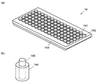
도 1은 본 발명에 관한 수지 성형 장치의 제1 실시 형태를 나타내는 측면도(도 1의 (a)) 및 그 부분 확대도(도 1의 (b))이다.
도 2는 제1 실시 형태의 수지 성형 장치의 평탄도 조정부에 대해서 설명하는 도면이다.
도 3은 제1 실시 형태의 수지 성형 장치의 동작을 설명하는 도면이다.
도 4는 제1 실시 형태의 수지 성형 장치의 동작을 이어서 설명하는 도면이다.
도 5는 수지 성형품의 개략도이다.
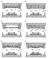
도 6은 형체결 시험 결과에 근거하여 평탄도 조정부의 조정 부재를 조정하는 일 예이다.
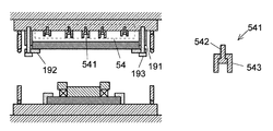
도 7은 제1 실시 형태의 수지 성형 장치의 변형예의 부분 확대도이다.
도 8은 본 발명에 관한 수지 성형 장치의 제2 실시 형태를 나타내는 측면도(좌측도) 및 그 부분 확대도(우측도)이다.
도 9는 본 발명에 관한 수지 성형 장치로서 성형 모듈을 복수개 접속한 예를 나타내는 평면도이다. Fig. 1 is a side view (Fig. 1 (a)) and a partial enlarged view thereof (Fig. 1 (b)) showing the first embodiment of the resin molding apparatus according to the present invention.
Fig. 2 is a view for explaining the flatness adjusting section of the resin molding apparatus of the first embodiment. Fig.
3 is a view for explaining the operation of the resin molding apparatus of the first embodiment.
4 is a view for explaining the operation of the resin molding apparatus of the first embodiment.
5 is a schematic view of a resin molded article.
6 shows an example of adjusting the adjusting member of the flatness adjusting section based on the result of the mold clamping test.
7 is a partial enlarged view of a modified example of the resin molding apparatus of the first embodiment.
8 is a side view (left side view) and a partially enlarged view (right side view) showing a second embodiment of the resin molding apparatus according to the present invention.
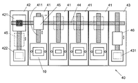
9 is a plan view showing an example in which a plurality of molding modules are connected as a resin molding apparatus according to the present invention.
본 발명에 관한 수지 성형 장치, 수지 성형 방법, 및 수지 성형품의 제조 방법의 실시 형태에 대해서, 이하, 도 1~도 9를 이용하여 설명한다. Embodiments of a resin molding apparatus, a resin molding method and a resin molded product manufacturing method according to the present invention will be described below with reference to Figs. 1 to 9. Fig.
(1) 제1 실시 형태(1) First Embodiment
(1-1) 제1 실시 형태의 수지 성형 장치(10)의 구성(1-1) Configuration of the
도 1의 (a)에 본 실시 형태의 수지 성형 장치(10)의 전체 구성을, 도 1의 (b)에 수지 성형 장치(10)의 성형형(16) 주변의 요부 구성을 나타낸다. Fig. 1 (a) shows the overall configuration of the
본 실시 형태의 수지 성형 장치(10)는, 바닥면에 재치된, 평면 형상이 직사각형인 기반(基盤)(131) 상에 구성되어 있다. 기반(131)의 네 모서리에는 4개의 타이 바(tie bar)(132)(2개의 타이 바(132)만 도시)가 세워 마련되어 있다. 기반(131)의 상부에는 제1 플래턴(platen)(상부 플래턴, 본 발명에서의 고정 플래턴)(11)과 제2 플래턴(하부 플래턴, 본 발명에서의 가동 플래턴)(12)이 배치되어 있다. 제1 플래턴(11)의 네 모서리에는 타이 바(132)의 상단이 고정되어 있고, 제1 플래턴(11)은 부동(不動) 상태로 되어 있다. 제2 플래턴(12)의 네 모서리에는 타이 바(132)가 관통하는 관통공이 형성되어 있고, 제2 플래턴(12)은 상하 이동 가능하게 되어 있다. 기반(131)과 제2 플래턴(12)의 사이에는, 상기 제 2 플래턴(12)을 상하 이동시키는 구동 기구인 토글 링크(133)(본 발명에서의 형체결 기구)가 배치되어 있다. 토글 링크(133)는 2조의 토글 기구를 가지고 있으며, 그들 2조의 토글 기구의 작용점은 제2 플래턴(12)의 하면에 장착되어 있다. 제1 플래턴(11)과 제2 플래턴(12)의 사이에는, 후술하는 바와 같이 성형형(16) 등이 배치된다. 본 실시 형태의 수지 성형 장치(10)에서는, 제1 플래턴(상부 플래턴)(11)을 부동 상태의 고정 플래턴, 제2 플래턴(하부 플래턴)(12)을 가동 플래턴으로 했지만, 이들은 반대라도 좋다. 또, 제1 플래턴(11)과 제2 플래턴(12)의 양쪽 모두를 가동 플래턴으로 해도 좋다. 그 경우에는, 제1 플래턴(11)과 제2 플래턴(12)의 각각에 대해서 토글 링크(133) 등의 형체결 기구를 배치해 둔다. 게다가, 본 실시 형태에서는 구동 기구(형체결 기구)로서 토글 링크(133)를 이용하고 있지만, 그 외, 유압식, 액압식, 공압식 구동 기구나, 볼 나사 등을 이용한 형체결 기구 등을 이용할 수도 있다. The
제1 플래턴(11)의 하측에는 상부 히터 플레이트(151), 평탄도 조정부(14), 및 성형형(16)의 상형(161)(본 발명에서의 제1 성형형)이 위로부터 순서대로 배치되어 있다. 히터 플레이트는, 철, 스테인리스강, 혹은 Ti-6Al-4V 합금과 같은 금속제의 판재 내에 히터가 내장된 것이다. 본 실시 형태의 구성 요소 및 그들 배치 순서는 일례이며, 평탄도 조정부(14)가, 상형(161)(본 발명에서의 제1 성형형)의 형면과 하형(162)(본 발명에서의 제2 성형형)의 형면의 평행도, 혹은 성형형(16)에 의해 성형되는 수지 성형품의 평탄도를 조정할 수 있는 위치에 배치되어 있으면 되며, 구성 요소나 그 배치 순서는 적절히 변경할 수 있다. 성형형(16)의 상형(161)은, 제1 플래턴(11)의 형(型)배치부에 배치된다. 이 형배치부는, 많은 경우, 제1 플래턴(11)의 판면의 중앙부이지만, 반드시 중앙부가 아니어도 좋다. 또, 상형(161)의 형면은 하형(162)과 대향하는 면이며, 예를 들면 기판(22)이 장착되는 면을 포함한다. 또, 하형(162)의 형면은 상형(161)과 대향하는 면이며, 예를 들면 캐비티(C)의 저면(후술하는 저면 부재(1623)의 상면)을 포함한다. 또, 제1 플래턴(11)의 하면의 둘레 가장자리부에는, 상하에 O링(173, 175)이 장착된 상부 외기 차단 부재(174)가 배치되어 있다. 성형형(16)의 형체결시에는, 이 O링(173), 상부 외기 차단 부재(174), 및 O링(175)과 후술의 하부 외기 차단 부재(172) 및 O링(171)에 의해서 성형형(16)이 배치된 공간이 외부로부터 차단된다. The
제2 플래턴(12) 상에는, 하부 히터 플레이트(152), 및 성형형(16)의 하형(162)(본 발명에서의 제2 성형형)이 배치되어 있다. 성형형(16)의 하형(162)은 제2 플래턴(12)의 형배치부에 배치된다. 이 형배치부도, 반드시 제2 플래턴(12)의 판면의 중앙부가 아니라도 되지만, 상형(161)과 하형(162)은 대향하여 배치한다. 하형(162)은, 하형 베이스 플레이트(1621), 상기 하형 베이스 플레이트(1621)를 형배치부에 안내하는 가이드 부재인 하형 사이드 블록(1622), 상기 하형 베이스 플레이트(1621)의 상면 중앙부에 고정된 저면 부재(1623), 및 상기 하형 베이스 플레이트(1621)의 상면에 스프링 등의 부재(1624)를 매개로 하여 배치된, 상기 저면 부재(1623)를 둘러싸는 프레임 모양의 측면 부재(1625)로 구성되어 있다. 후술하는 수지 성형시에는, 저면 부재(1623)의 상면과 측면 부재(1625)의 내측면에 의해서 캐비티(C)가 구성된다. 또, 제2 플래턴(12)의 상면의 둘레 가장자리부에는 O링(171)을 매개로 하여 하부 외기 차단 부재(172)가 배치되어 있다. A
평탄도 조정부(14)는, 도 2에 나타내는 바와 같이, 복수의 원기둥 모양의 조정 부재(141)와, 상기 조정 부재(141)를 1개씩 수용하는 조정 부재 수용부(142)가 복수, 격자 모양으로 배치된 조정 부재 용기(143)로 구성된다. 조정 부재 수용부(142)의 깊이는 조정 부재(141)의 높이보다도 낮고(얕고), 따라서, 조정 부재 수용부(142)에 조정 부재(141)를 수용하면 조정 부재(141)의 상부가 조정 부재 수용부(142)로부터 돌출된 상태가 된다. 본 실시예의 조정 부재(141)는, 상부 히터 플레이트(151)로부터의 열을 효율 좋게 상형(161)에 전달할 수 있도록, 열전도율이 높은 동일종의 금속(합금을 포함함)으로 구성되어 있다. 다만, 이것은 바람직한 일 형태로서, 조정 부재(141)를 열전도율이 높은 금속에 의해 구성하는 것은 본 발명에 필수 요건은 아니다. 도 2에는, 1개소를 제외하고 모든 조정 부재 수용부(142)에 조정 부재(141)를 수용한 상태를 나타내고 있지만, 실제의 사용시에는, 수지 성형시에 생기는 상형(161)의 형면(하형(162)과 대향하는 면)의 비틀림이나 만곡 등의 변형을 조정하도록, 복수의 조정 부재 수용부(142) 중, 조정 부재(141)를 수용하는 개소와, 조정 부재(141)를 수용하지 않는 개소를 마련함으로써, 조정 부재 용기(143)에서의 조정 부재(141)의 국소적인 수(數)로 조밀(粗密)하게 마련해 둘 수 있다. 평탄도 조정부(14)는, 상부 히터 플레이트(151)에 장착된, 단면이 L자 모양인 조정 기구 사이드 블록(18)에 의해 조정 부재 용기(143)의 하면을 측방으로부터 지지하는 것에 의해 장착된다. 2, the
또, 도 2의 (a)에서는, 동일종의 금속으로 이루어지며 동일한 단면적 및 높이를 가지는 조정 부재(141)를 조정 부재 수용부(142)에 수용한 상태를 도시하고 있지만, 강성(재질) 및 높이 중 한쪽 또는 양쪽 모두가 다른 조정 부재를 이용할 수도 있다. 또한, 도 2의 (b)에 나타내는 바와 같이, 조정 부재 수용부(142)의 내경(구멍 지름) 및 깊이와 대략 동일한 외경 및 높이를 가지며, 내측에 관통공이 형성된 어태치먼트(144)를 이용하는 것에 의해, 조정 부재 수용부(142)보다도 외경이 작은(가는) 조정 부재(145)를 이용할 수도 있다. 즉, 조정 부재 용기(143)에서의 복수의 조정 부재 수용부(142) 중 일부에 가는 조정 부재(145)를 수용하고, 다른 일부에 굵은(통상의) 조정 부재(141)를 수용할 수 있다. 또한, 도 2에서는, 원통모양의 조정 부재(141)를 이용하고 있지만, 다른 형상(각 기둥 모양, 타원 기둥 모양등)의 조정 부재(141)를 이용할 수도 있다. 2 (a) shows a state in which the adjusting
본 실시 형태에서는, 상부 히터 플레이트(151)와 상형(161)의 사이에 평탄도 조정부(14)를 배치하고 있지만, 하형(162)과 하부 히터 플레이트(152)의 사이에 평탄도 조정부(14)를 배치할 수도 있다. 즉, 상형(161)측과 하형(162)측 중 한쪽 또는 양쪽 모두에 평탄도 조정부(14)를 배치할 수 있다. The
상형(161)의 측방에는 상부 히터 플레이트(151)에 고정된 상형 사이드 블록(191)이 배치되고, 상기 상형 사이드 블록(191)의 하단에는 상형(161)을 지지하는 누름판(192)(본 발명에서의 지지 부재)이 장착되어 있다. 누름판(192)은, 해당 누름판(192)과 상형 사이드 블록(191)을 관통하여 상부 히터 플레이트(151)에 형성된 나사 구멍에 삽입되는 볼트(193)(본 발명에서의 고정 부재)에 의해서 고정되어 있다. 볼트(193)를 느슨하게 하면 누름판(192) 및 상형(161)을 하부로 이동시킬 수 있어, 필요에 따라서 상형(161)을 교환할 수 있다. 즉, 상형 사이드 블록(191), 누름판(192), 및 볼트(193)는 본 발명에서의 장착 기구에 상당한다. 그리고, 이 장착 기구에 의해 상형(161)은 제1 플래턴(11)에 착탈 가능하게 장착된다. An upper
(1-2) 제1 실시 형태의 수지 성형 장치(10)의 동작(1-2) Operation of the
제1 실시 형태의 수지 성형 장치(10)의 동작을, 도 3 및 도 4를 이용하여 설명한다. 본 실시 형태의 수지 성형 장치(10)에서는 여러가지 판 모양 부재(금속 기판, 수지 기판, 유리 기판, 세라믹스 기판, 회로 기판, 반도체 웨이퍼, 리드 프레임 등)을 수지 성형할 수 있다. 여기에서는 전자 부품(21)이 장착된 기판(22)을 피성형물로 하고, 해당 전자 부품(21)을 경화 수지(26)에 의해 씰링한 수지 씰링품을 제작하는 경우를 예로서 설명하지만, 이것 이외의 수지 성형품도 이와 같이 제작할 수 있다. The operation of the
도 3의 (a)는, 평탄도 조정부(14)의 조정을 행하기 전의 수지 성형 장치(10)의 성형형(16)의 주변의 확대도이다. 3 (a) is an enlarged view of the periphery of the molding die 16 of the
평탄도 조정부(14)를 조정할 때에는, 먼저, 볼트(193)를 느슨하게 하여 상형(161)을 누름판(192)과 함께 하향 이동시킨다(도 3의 (b)). 이어서, 평탄도 조정부(14)를 도면의 바로 앞 방향(혹은 안쪽 방향)으로 슬라이드시켜 떼어낸다(도 3의 (c))). 이와 같이, 본 실시 형태의 수지 성형 장치(10)는, 상형(161)을 지지하는 누름판(192)과, 상기 누름판(192)에 의해 상형(161)을 지지한 채로 상기 누름판(192)을 제1 플래턴(11)에 고정 및 고정 해제하는 볼트(193)를 구비하고 있으며, 이들에 의해서, 누름판(192)을 제1 플래턴(11)으로부터 고정 해제한 상태에서, 상형(161)을 떼어내지 않고 평탄도 조정부(14)를 제1 플래턴(11)과 상형(161)의 사이에 삽입 및 취출할 수 있도록 하고 있다. 평탄도 조정부(14)를 착탈할 때에 성형형(16)(상형(161)이나 하형(162))을 떼어내지 않으면 안 되는 구성의 경우, 성형형(16)의 착탈에 시간이 든다. 또, 수지 성형 장치(10)로부터 떼어내면 성형형(16)이 냉각되기 때문에, 성형형(16)을 장착한 후에 소정의 온도까지 가열하는데 시간이 걸린다고 하는 문제도 있다. 본 실시예의 수지 성형 장치(10)에서는, 상형(161)을 수지 성형 장치(10)로부터 떼어내지 않고 평탄도 조정부(14)를 떼어낼 수 있기 때문에, 이들 문제가 생기지 않고, 효율적으로 평탄도 조정부(14)의 조정 및 수지 성형을 행할 수 있다. 물론, 필요에 따라서, 평탄도 조정부(14)의 착탈시에 함께 상형(161)을 착탈해도 괜찮다. When adjusting the
다음으로, 떼어낸 평탄도 조정부(14)의 조정 부재 수용부(142)에 수용되어 있는 조정 부재(141)의 배치나, 사용하는 조정 부재(141)의 높이, 지름(단면적), 또는/및 강성(재질)을 변경한다. 구체적으로는, 성형형(16)을 형체결했을 때에 상형(161)의 형면과 하형(162)의 형면이 소정의 평행도가 되고, 그 결과로서 상기 성형형(16)을 이용하여 성형되는 수지 성형품이 소정의 평탄도가 되도록, 조정 부재(141)의 배치 등을 변경한다. 예를 들면, 후술하는 형체결 시험에 의해 제작한 수지 성형품에서 국소적으로 두껍게 되어 있는 개소의 주변에, 그것 이외의 장소에 배치하는 조정 부재보다도 지름(단면적)이 큰 조정 부재(141)를 배치한다. 이것에 의해, 수지 성형품의 평탄도가 유지되어, 두께의 불균일이 억제된다. 또, 하형(162)과 하부 히터 플레이트(152)의 사이에 평탄도 조정부(14)를 마련한 경우에는, 상하 양방향으로부터 수지 성형품의 평탄도를 조정하는 것에 의해 조정의 자유도를 높이고, 수지 성형품의 평탄도를 미세하게 조정할 수 있다. 본 실시 형태에서는, 중앙부에 단면적이 큰 조정 부재(141)를 배치하고, 둘레 가장자리부에는 단면적이 작은 조정 부재(145)를 배치한다. 조정 부재(141, 145)의 재배치를 끝내면, 평탄도 조정부(14)를 다시 수지 성형 장치(10)에 셋팅한다(도 3의 (d)). 그리고, 볼트(193)를 조이는 것에 의해, 누름판(192) 및 상형(161)을 상향 이동시켜 평탄도 조정부(14)를 고정한다(도 3의 (e)). 본 발명에 관한 수지 성형 방법의 준비 공정은, 도 3의 (a)에 나타내는 바와 같은, 상기 각 부재로 이루어지는 수지 성형 장치를 사용 가능한 상태로 하는 공정에 상당하고, 도 3의 (b)~도 3의 (e)는 평탄도 조정부(14)를 이용한 수지 성형품의 평탄도의 조정 공정(혹은 성형형의 형면의 평행도의 조정 공정)이다. Next, the arrangement of the adjusting
평탄도 조정부(14)를 고정하면, 상부 히터 플레이트(151) 및 하부 히터 플레이트(152)를 동작시킨다. 이어서, 피성형물인, 전자 부품(21)이 장착된 기판(22)을 상형(161)의 소정 위치에 장착한다(도 3의 (f)). 본 실시예에서는, 상형(161)에 마련되어 있는 도시하지 않은 진공 흡착부에 의해 기판(22)을 상형(161)에 장착하지만, 장착구를 이용하는 등, 다른 방법으로 기판(22)을 상형(161)에 장착해도 괜찮다. 본 실시 형태에서는, 평탄도 조정부(14)를 고정한 후이고 기판(22)을 상형(161)에 장착하기 전에 상부 히터 플레이트(151) 및 하부 히터 플레이트(152)를 동작시키고 있지만, 성형형(16)의 형체결 개시까지 상형(161) 및 하형(162)을 소정의 온도로 가열 가능한 한, 상부 히터 플레이트(151) 및 하부 히터 플레이트(152)를 동작시키는 타이밍을 적절히 변경할 수 있다. When the
기판(22)을 상형(161)에 장착한 뒤, 하형(162)의 캐비티(C)를 덮도록 이형 필름(23)을 장착한다. 이형 필름(23)은 하형(162)에 마련된 도시하지 않은 흡착 기구에 의해 측면 부재(1625)의 상면 및 내벽면과 저면 부재(1623)의 상면에 밀착하도록 장착된다. 또, 이형 필름(23)이 장착된 캐비티(C)에 과립상 혹은 분말상의 수지 재료(24)를 소정량, 공급한다(도 4의 (a)). 하형(162)의 캐비티(C)에 공급된 수지 재료(24)는 하형(162)을 매개로 하여 하부 히터 플레이트(152)에 의해, 기판(22)은 상형(161)을 매개로 하여 상부 히터 플레이트(151)에 의해, 모두 소정의 온도(예를 들면 170~180℃)로 가열되고, 수지 재료(24)가 용융하기 시작한다(도 4의 (b)). 또, 본 실시 형태에서는 캐비티(C)에 이형 필름(23)을 장착한 후에 수지 재료(24)를 공급하고 있지만, 이형 필름과 수지 재료를 동시에 캐비티(C)에 공급하는 등, 다른 방법에 의해 이형 필름 및 수지 재료를 공급할 수도 있다. 이것은, 예를 들면, 프레임 모양 부재의 저면에 이형 필름을 펼쳐 마련하여 형성한 수지 수용부에 수지 재료를 공급하고, 이것을 캐비티(C)의 상부로 이동시킨 후, 이형 필름을 수지 재료와 함께 캐비티(C)에 낙하시키는 것에 의해 실시할 수 있다. 또, 본 실시 형태에서는 과립상 혹은 분말상의 열경화성 수지 재료를 이용하고 있지만, 수지 재료의 종류는 이것에 한정되지 않고, 과립상이나 분말상의 수지 재료 외에, 액상 수지, 시트 모양 수지, 혹은 태블릿 모양 수지 재료 등을 이용할 수도 있다. 예를 들면, 에폭시 수지나 실리콘 수지 등의 열경화성 수지 외에, 혹은 열가소성 수지를 이용할 수도 있다. 예를 들면, 상온에서 액체의 열경화성 수지를 이용하는 경우, 가열에 의해 일단 점도가 저하된 후, 더 가열하여 경화(고체화)시킨다. 그 외, 열경화성 수지 혹은 열가소성 수지를 일부에 포함한(다른 재료와 혼합한) 복합 재료라도 좋다. After the
다음으로, 토글 링크(133)를 동작시켜 제2 플래턴(12)을 상향 이동시킨다. 이것에 의해, 제2 플래턴(12) 상에 배치되어 있는 하부 히터 플레이트(152) 및 하형(162)가 상향 이동한다. 이 동작에 의해, 먼저 측면 부재(1625)의 상면이 기판(22)의 하면에 접촉한다. 이 상태에서 제2 플래턴(12) 등을 더 상향 이동시켜 가면, 탄성 부재(1624)가 수축하여 측면 부재(1625)에 대해서 상대적으로 저면 부재(1623)가 상승하고, 기판(22)에 장착된 전자 부품(21)이 용융 수지(25)에 침지된다. 이 상태에서 성형형(16)이 형체결된다(도 4의 (c)). 이 형체결 상태를 일정시간 유지하고, 용융 수지(25)를 더 가열하면, 용융 수지(25)가 경화하여 전자 부품(21)이 경화 수지(26)에 의해 씰링된다. 수지 씰링 후, 토글 링크(133)를 다시 동작시켜 제2 플래턴(12)을 하향 이동시키는 것에 의해 성형형(16)을 형개방한다 (도 4의 (d)). 본 실시 형태에서는, 캐비티(C)에 이형 필름(23)을 장착하고 있기 때문에, 경화 수지(26)가 캐비티(C)로부터 스무스하게 떨어져 수지 성형품을 이형 할 수 있다. 본 실시 형태에서는, 여기까지의 공정이 수지 성형 방법에 상당한다. Next, the
본 실시 형태의 수지 성형 방법에 의해 제작한 수지 씰링품을 떼어낸 후, 그 둘레 가장자리부를 절단하여 여분의 경화 수지를 절단하거나, 혹은 상기 예와 같이 복수의 전자 부품을 일괄하여 수지 씰링하는 경우에는, 그들을 소정의 위치에서 절단하여 개편화하거나 하는 처리가 행하여진다. 즉, 수지 성형 방법에 의해 제작한 중간 제품을 최종적인 제품으로서 완성시키는 공정이 행하여지는 것이 많다. 본 실시 형태에서의 수지 씰링품(수지 성형품)의 제조 방법은, 상술의 수지 씰링 방법(수지 성형 방법)의 각 공정에 더하여, 이러한 공정도 포함하고 있다. When the resin sealing material produced by the resin molding method of the present embodiment is removed and the peripheral portion thereof is cut to cut the excess cured resin or when a plurality of electronic parts are resin sealed together as in the above example , And a process of cutting them and cutting them at a predetermined position is performed. In other words, a step of completing the intermediate product produced by the resin molding method as a final product is often performed. The manufacturing method of the resin sealing product (resin molded product) in the present embodiment includes these steps in addition to the respective steps of the resin sealing method (resin molding method) described above.
본 실시 형태의 수지 성형 장치(10)가 특징적인 구성 요소로서 구비하는 평탄도 조정부(14)의 조정 방법에 대해 설명한다. A method of adjusting the
도 5는, 본 실시 형태의 수지 성형 장치(10)에 의해 제조되는 수지 성형품의 일례의 개략도이다. 이 수지 성형품은, 상술한 바와 같이, 기판(22)에 장착한 전자 부품(21)을 경화 수지(26)에 의해 씰링한 것이다. 도 5에 나타내는 바와 같이, 수지 성형품의 두께는 기판(22)의 두께와 수지 씰링부의 두께의 합계이다. 수지 성형품의 두께는, 많은 경우, 수백㎛~수mm 정도이며, 그러한 수지 성형품의 국소적인 두께의 불균일(제일 두꺼운 부분과 제일 얇은 부분의 차이)을 100㎛ 이하로 하는 것이 요구된다. 또, 특히 최근에는, 이것을 10㎛ 이하로 하는 것이 요구되는 경우가 있다. 즉, 수지 성형품의 국소적인 두께의 불균일을 없애는 것에 의해 수지 성형품의 평탄도를 높이는 것이 요구되고 있다. 5 is a schematic view of an example of a resin molded article manufactured by the
제1 플래턴(11), 제2 플래턴(12), 상부 히터 플레이트(151), 하부 히터 플레이트(152), 상형(161), 및 하형(162)과 같은 수지 성형 장치(10)의 각 부재는, 각각 공차의 범위 내에서 제조 시점에서의 형상의 불균일을 가지고 있다. 1개씩의 부재의 형상의 불균일은 작지만, 수지 성형 장치(10)로서 각 부재를 조립 또는 장착하면, 그들 형상의 불균일이 누적되어 성형형(16)의 형면의 평행도에 영향을 미친다. 이렇게 하여 형면의 평행도가 손상된 상태의 성형형(16)에 의해 수지 씰링을 행하면, 제조되는 수지 씰링품의 평탄도가 크게 손상된다. 또, 성형형(16)의 형체결시에는, 토글 링크(133)가 제2 플래턴(12)의 2개소(예를 들면 본 실시 형태의 경우)에 힘을 가하여 상향 이동시키고, 또 부동 상태의 제1 플래턴(11)은 4개(예를 들면 본 실시 형태의 경우)의 타이 바(132)가 고정된 개소에서 하향으로 끌어당겨진다. 즉, 제1 플래턴(11)과 제2 플래턴(12) 모두에 있어서 특정의 개소에 국소적으로 힘이 가해지게 되며, 이것에 의해서도 성형형(16)의 형면의 평행도가 저하되고, 수지 씰링품의 평탄도가 손상되는 경우가 있다. 종래, 형체결시에 제1 플래턴(11)에 비틀림이 생기면, 그대로 상형(161)이 비틀리게 되어, 수지 씰링품의 평탄도가 손상되는 경우가 있었다. 이것에 대해, 본 실시 형태에서는 형체결시에 상형(161)에 비틀림이 생기는 경우에도 평탄도 조정부(14)의 조정 부재(141)의 배치 등을 적절히 조정하는 것에 의해 그 형상의 불균일의 영향을 억제하여, 수지 성형품의 평탄도를 일정하게 유지할 수 있다. The angle of the
성형형(16)의 형면의 평행도나 수지 성형품의 평탄도에 영향을 미치는 요인은 상기와 같은 공차나 성형형(16)의 형체결시의 힘의 작용 뿐만 아니라, 히터 플레이트에 의한 가열시에 각 부재의 온도가 위치에 의해서 조금씩 달라, 불균일하게 변형되는 것 등, 여러가지이고 모든 요인을 정확하게 특정하는 것은 어렵다. 그러나, 이들에 기인하는 수지 성형품의 평탄도의 불균일은, 사전에 형체결 시험을 행하는 등에 의해 확인해 둘 수 있다. 형체결 시험에서는, 도 6의 (a)에 나타내는 바와 같이, 동일한 조정 부재(141)를 균등하게 배치한 상태에서 성형형(16)을 형체결하고 수지 성형하여, 시험품을 제작한다. 그리고, 그 시험품의 평탄도를 계측한다. 예를 들면, 도 6의 (a)에 나타내는 바와 같이, 시험편(의 경화 수지(26))이 중앙부에서 두껍고 둘레 가장자리부에서 얇게 되어 있는 경우에는, 도 6의 (b)에 나타내는 바와 같이, 중앙부에 굵은(통상의) 조정 부재(141)를 배치하고, 둘레 가장자리부에 그것보다도 지름(단면적)이 작은 조정 부재를 배치하면 좋다. 예를 들면, 수지 성형품의 씰링 수지(경화 수지(26))가 두껍게 되어 있는 개소에서는, 다른 개소(씰링 수지가 얇은 개소)보다도 성형형으로부터의 압압력(하중)이 작게 되어 있는 것이 고려되어진다. 즉, 성형형(16)의 압압력이 위치에 따라서 다르기 때문에, 위치에 의해서 형체결시의 성형형의 변위량에 차이가 생기고, 그 결과로서 씰링 수지의 두께에 차이가 생기고 있다고 생각되어진다. 도 6의 (b)과 같이, 씰링 수지가 두껍게 되어 있는 개소에 굵은(휘기 어려운) 조정 부재(141)를, 씰링 수지가 얇게 되어 있는 개소에 가는(휘기 쉬운) 조정 부재를 배치함으로써, 상형(161)에 대한 압압력(하중)을 크게 하고, 씰링 수지의 두께를 일정하게(즉 평탄하게) 할 수 있다. 또, 도 6의 (c)에 나타내는 바와 같이, 중앙부에 높은 조정 부재(141)를 배치하고, 둘레 가장자리부에 그것보다도 낮은 조정 부재를 배치하는 것에 의해, 성형형(16)의 형체결시에 작용하는 힘의 크기를 조정하여 수지 씰링품의 평탄도를 일정하게 유지할 수도 있다. 이 경우, 형체결시에는, 먼저, 높은 조정 부재를 배치한 개소에서 압압력이 작용하고, 형체결을 더 계속하면 낮은 조정 부재를 배치한 개소에서도 상형(161) 또는/및 상부 히터 플레이트(151)가 서서히 변형하여 조정 부재에 접촉하여 압압력이 작용한다. 이와 같이 높이가 다른 조정 부재를 이용하여 성형형의 변위량을 조정하는 것에 의해서도 씰링 수지의 두께를 일정하게 할 수 있다. 이것에 의해, 불량품(국소적인 두께의 불균일이 큰 수지 성형품)이 생길 가능성이 억제된다. Factors influencing the degree of parallelism of the mold surface of the mold 16 and the flatness of the molded resin product are not only the above-mentioned tolerance and the force at the time of mold clamping of the mold 16, It is difficult to pinpoint various and all factors, such as the temperature of the member being slightly different and nonuniformly deformed by position. However, the unevenness of the flatness of the resin molded article due to these can be confirmed by performing a mold clamping test in advance. In the mold clamping test, as shown in Fig. 6A, the molds 16 are clamped and resin-molded under the condition that the same adjusting
(1-4) 평탄도 조정부의 변형예(1-4) Variation of Flatness Adjustment Example
제1 실시 형태의 수지 성형 장치(10)에서는, 조정 부재 수용부(142)가 마련된 조정 부재 용기(143)에 조정 부재(141)를 셋팅하는 것에 의해 평탄도 조정부(14)를 구성했지만, 도 7에 나타내는 바와 같은 평탄도 조정부(54)를 이용할 수도 있다. 이 평탄도 조정부(54)의 조정 부재(541)는, 선단에 나사 홈이 형성된 볼트(542)와, 상면 중앙에 볼트(542)를 삽입하는 구멍이 형성된 조정 핀(543)을 가지고 있다. 조정 핀(543)에는 다른 높이의 것이 복수, 준비되어 있다. 이 평탄도 조정부(54)를 이용할 때에는, 먼저, 상기 실시예와 마찬가지로 볼트(193)를 느슨하게하여 상형(161)을 하향 이동시킨다. 그리고, 장착 위치에 따른 높이 조정 핀(543)을 선택하고, 그 상면의 구멍에 볼트(542)를 통과시킨다. 그리고, 상부 히터 플레이트(151)의 하면에 미리 다수, 2차원적으로(격자 모양이나 허니콤 모양으로) 배치된 나사 구멍 중 1개에 조정 부재(541)를 고정한다. 이 때, 필요에 따라서 상형(161)을 떼어내어 교환할 수도 있다. 모든 조정 부재(541)를 셋팅하여 끝내면, 볼트(193)를 죄어 상형(161)을 상향 이동시킨다. 이러한 평탄도 조정부(54)를 이용하는 것에 의해서도, 제1 실시 형태의 수지 성형 장치(10)와 마찬가지로, 성형형(16)의 형면의 평행도나 수지 성형품의 평탄도를 유지할 수 있다. 물론, 조정 핀(543)의 높이 뿐만 아니라, 제1 실시 형태의 수지 성형 장치에서의 조정 부재(141)와 마찬가지로, 조정 핀(543)의 단면적, 위치, 또는/및 강성(재질)을 변경할 수도 있다. In the
(2) 제2 실시 형태의 수지 성형 장치(30)(2) In the
제2 실시 형태의 수지 성형 장치(30)는, 도 7에 나타내는 바와 같이, 기반(331) 상에 4개의 타이 바(332)가 세워 마련됨과 아울러 토글 링크(333)가 마련되어 있다고 하는 점에서는 제1 실시 형태의 수지 성형 장치(10)와 동일하다. 타이 바(332)에는 상부 가동 플래턴(321)과 하부 가동 플래턴(322)이 상하로 이동 가능하게 유지되어 있고, 타이 바(332)의 상단에는 고정 플래턴(31)이 고정되어 있다. The
고정 플래턴(31)과 상부 가동 플래턴(321)의 사이에는, 제1 평탄도 조정부(34A), 제1 상부 히터 플레이트(351A) 및 제1 하부 히터 플레이트(352A), 및 제1 성형형(36A)(제1 상형(361A) 및 제1 하형(362A))이 마련되어 있다. 또, 상부 가동 플래턴(321)과 하부 가동 플래턴(322)의 사이에는, 제2 평탄도 조정부(34B), 제2 상부 히터 플레이트(351B) 및 제2 하부 히터 플레이트(352B), 및 제2 성형형(36B)(제2 상형(361B) 및 제2 하형(362B))이 마련되어 있다. 제1 성형형(36A)과 제2 성형형(36B)은, 평면에서 보아 동일 위치(형배치부)에 배치된다. 토글 링크(333)는 하부 가동 플래턴(322)의 하면에 장착되어 있다. 또, 타이 바(332)의 상단은, 고정 플래턴(31)의 하면에 고정되어 있다. A first
제1 평탄도 조정부(34A)와 제2 평탄도 조정부(34B)는, 모두 제1 실시예의 평탄도 조정부(14)와 마찬가지로, 조정 부재(341)와 조정 부재 용기(343)로 구성된다. 물론, 상술한 변형예의 조정 부재(541)와 같이 볼트(542)와 조정 핀(543)으로 이루어지는 것을 이용해도 좋다. 또, 성형형의 하형의 측에 동일한 평탄도 조정부를 배치할 수도 있다. 본 실시 형태에서도, 제1 실시 형태와 마찬가지로, 수지 성형 장치(30)의 형체결시의 제1 성형형(36A)의 형면과 제2 성형형(36B)의 형면의 평행도를 유지하고, 수지 성형품의 평탄도가 일정하게 되도록 조정 부재(341)의 수밀도(數密度)(혹은 높이, 단면적, 강성(재질))이 설정된다. The first
제2 실시 형태의 수지 성형 장치(30)는, 토글 링크(333)에 의해서 하부 가동 플래턴(322)이 밀어 올려지는 것에 의해, 제2 하부 히터 플레이트(352B), 제2 성형형(36B), 제2 상부 히터 플레이트(351B), 및 제2 평탄도 조정부(34B)를 매개로 하여 상부 가동 플래턴(321)도 밀어 올려진다. 이것에 의해, 상부 가동 플래턴(321)과 하부 가동 플래턴(322)의 사이, 및 상부 가동 플래턴(321)과 고정 플래턴(31)의 사이에서, 각각 형체결이 이루어진다. 이와 같이, 본 실시 형태에서는, 한번의 토글 링크(333)의 동작에 의해서 2개의 성형형을 형체결하는 것이 가능하기 때문에, 수지 성형품의 제조 효율이 향상된다. 이 수지 성형 장치(30)에서는, 토글 링크(333)의 동작에 의해 하부 가동 플래턴(322), 제2 성형형(36B), 상부 가동 플래턴(321) 등을 순차적으로 상승시키는 구성으로 했지만, 그 외, 랙 앤드 피니언 등을 가지는 연결 기구를 이용하여 상부 가동 플래턴(321)과 하부 가동 플래턴(322)을 연결하는 것에 의해, 상부 가동 플래턴(321)과 하부 가동 플래턴(322)이 연동하여 움직이도록(예를 들면 하부 가동 플래턴(322)의 이동거리가 상부 가동 플래턴(321)의 이동거리의 2배가 되도록) 구성하는 것도 가능하다(예를 들면 특허 문헌 3).The
(3) 모듈화된 수지 성형 장치의 예(3) Example of modularized resin molding apparatus
도 9에, 제1 실시 형태의 수지 성형 장치(10)를 구비한 성형 모듈을 하나 또는 복수 조 가지는 장치(40)를 나타낸다. 환언하면, 제1 실시 형태의 수지 성형 장치(10)는 성형 모듈에 상당한다. 이하에서는 도 8의 장치(40)의 전체(수지 성형 유닛)에 대해서도 「수지 성형 장치」라고 부른다. 이하, 도 1의 (a) 및 도 9를 참조하여, 수지 성형 장치(40)에 대해 설명한다. Fig. 9 shows a
수지 성형 장치(40)는, 복수 조의 성형 모듈(41)과, 1조의 수지 재료·기판 보충 모듈(42)과, 1조의 수지 성형품 반출 모듈(43)과, 그들 각 모듈을 관통하는 이동 기구(44)를 가진다. 또, 수지 성형 장치(40)는, 이동 기구(44)에 의해 수지 재료·기판 보충 모듈(42) 및 복수 조의 성형 모듈(41)의 사이를 이동할 수 있는 수지 재료·기판 공급 장치(45)와, 이동 기구(44)에 의해 복수 조의 성형 모듈(41) 및 수지 성형품 반출 모듈(43)의 사이를 이동할 수 있는 수지 성형품 반출 장치(46)를 가진다. 이하, 각 구성 요소에 대해 설명한다. The
각 성형 모듈(41)은, 제1 실시예의 수지 성형 장치(10)의 1조에 상당함과 아울러, 이동 기구(44)와 수지 성형 장치(10)의 사이에서 수지 재료·기판 공급 장치(45) 및 수지 성형품 반출 장치(46)를 이동시키는 부(副)이동 기구(411)를 가진다. Each of the
수지 재료·기판 공급 장치(45)는, 상부에 기판(22)을 수용하고, 하부에 예를 들면 과립상 또는 분말상의 수지 재료(24)를 수용하여, 이동 기구(44) 및 부이동 기구(411)에 의해 수지 성형 장치(10)의 근방까지 이동한 후에, 수지 성형 장치(10)의 캐비티(C)에 수지 재료(24)를 공급함과 아울러, 상형(161)에 기판(22)을 공급하는 장치이다. 캐비티(C)에 수지 재료(24)를 공급하는 장치의 구성에는, 예를 들면 특허 문헌 2에 기재된 수지 공급 장치와 동일한 것을 이용할 수 있다. 상형(161)에 기판(22)을 공급하는 장치에는, 일반적인 매니퓰레이터(manipulator)를 이용할 수 있다. 수지 재료·기판 보충 모듈(42)은, 수지 재료·기판 공급 장치(45)에 수지 재료(24)를 보충하는 호퍼를 가지는 수지 재료 보충 장치(421)와, 수지 재료·기판 공급 장치(45)에 보충되는 기판(22)을 보관하는 기판 보관부(매거진)(422)를 가진다. 또, 기판(22)과 수지 재료(24)의 공급을 반드시 1개의 장치에 의해 행할 필요는 없고, 이들을 다른 장치에 의해 공급해도 괜찮다. 또, 제1 실시 형태에서 설명한 바와 같이, 이형 필름(23)과 수지 재료(24)를 동시에 캐비티(C)에 공급하도록 구성할 수도 있다. The resin material /
수지 성형품 반출 장치(46)는, 이동 기구(44) 및 부이동 기구(411)에 의해 수지 성형 장치(10)의 근방까지 이동한 후에, 수지 성형 장치(10)의 상형(161)으로부터, 기판(22)의 표면에 장착된 전자 부품(21)이 경화 수지(26)에 의해 씰링된 수지 성형품을 매니퓰레이터에 의해서 떼어내어, 부이동 기구(411) 및 이동 기구(44)에 의해 수지 성형품 반출 모듈(43)로 반출하는 장치이다. 수지 성형품 반출 모듈(43)은, 반출된 수지 성형품을 보관하는 수지 성형품 보관부(매거진)(431)를 가진다. The resin molded product take-out
성형 모듈(41)은, 이동 기구(44)가 수지 재료·기판 공급 장치(45)를 이동시키는 방향(도 8의 횡방향)으로 장착 및 이탈 가능하고, 필요에 따라서 사후적으로 개수를 조정(증감)할 수 있다. 또, 여기에서는 성형 모듈(41)은 복수 조로 했지만, 1조만이라도 괜찮다. The
본 실시 형태의 수지 성형 장치(40)에 의하면, 성형 모듈(41) 중 1개에서 캐비티(C)로의 수지 재료(24)의 공급 및 상형(161)으로의 기판(22)의 장착을 행한 후, 상기 성형 모듈(41)에서 형체결을 행하고 있는 동안에, 다른 성형 모듈(41)에서 수지 재료(24)의 공급 및 기판(22)의 장착을 행할 수 있다. 그 때문에, 복수의 성형 모듈(41)에서 동시 병행으로 작업을 행할 수 있어, 수지 성형품의 생산 효율이 향상된다. 또, 필요에 따라서, 수지 성형 장치(40)의 제조 공정에서, 또는, 수지 성형 장치(40)의 완성 후에 사후적으로, 성형 모듈(41)을 자유롭게 증감시키는 것도 가능하다. According to the
상기 수지 성형 장치(40)에서는 수지 재료·기판 보충 모듈(42)과 수지 성형품 반출 모듈(43)을 따로 따로 마련했지만, 양자를 통합한 1개의 모듈로 해도 좋다. 즉, 수지 재료 보충 장치(421), 기판 보관부(422), 및 수지 성형품 보관부(431)를 1개의 모듈에 수용해도 괜찮다. 또, 수지 재료·기판 보충 모듈(42)에도 제1 실시예의 수지 성형 장치(10)를 1조 마련해도 좋다. 혹은, 기판의 공급에 이용하는 매니퓰레이터와 수지 성형품의 반출에 이용하는 매니퓰레이터를 겸용하는 것에 의해, 수지 재료·기판 공급 장치(45)와 수지 성형품 반출 장치(46)를 통합하여 1개의 장치로 할 수도 있다. Although the resin material /
상기 실시 형태는 모두 일례로서, 본 발명의 취지에 따라서 적절히 변경할 수 있다. The above embodiments are all examples, and can be suitably modified in accordance with the purpose of the present invention.
상기 실시 형태에서는 모두 압축 성형을 행하는 경우를 설명했지만, 트랜스퍼 성형 등, 다른 방법으로 수지 성형을 행하는 경우에도 상기 동일한 평탄도 조정부 등을 이용할 수 있다.In the above embodiments, the compression molding is performed in all cases. However, the same flatness adjusting section and the like can also be used when resin molding is performed by other methods such as transfer molding.
또, 상기 제1 실시 형태에서는, 수지 성형 방법의 각 공정에, 수지 성형품의 절단 공정을 포함하는 것을 수지 성형품의 제조 방법으로 했지만, 본 발명에 관한 수지 성형품의 제조 방법은, 이것에 한정되지 않고, 예를 들면, 본 발명의 수지 성형 방법에 의해 수지를 성형하는 공정(예를 들면 압축 성형 공정) 이외의 추가의 공정을 포함하고 있어도 괜찮고, 반드시 추가의 공정을 포함하지 않아도 좋다. 추가의 공정은 상술의 절단 공정 이외의 것이라도 좋다.In the first embodiment, the resin molded article manufacturing method includes the step of cutting the resin molded article in each step of the resin molding method. However, the manufacturing method of the resin molded article according to the present invention is not limited to this For example, an additional step other than a step (for example, a compression molding step) of molding the resin by the resin molding method of the present invention may be included, and it may not necessarily include an additional step. The additional step may be other than the above-mentioned cutting step.
또한, 상기 실시예에서는, 상형의 형면과 하형의 형면이 평행인 경우에 수지 성형품의 수지 씰링면(성형면)이 평탄하게 되는 경우에 대해 설명했다. 그러나, 수지 성형에 사용하는 수지의 특성에 따라서는, 상형의 형면과 하형의 형면이 평행한 상태로 성형형을 형체결하면, 형개방 후에 수지 성형품의 수지 성형면에 휨이 생기는 경우가 있다. 이러한 경우에는, 그 휨을 계산하여 평탄도 조정부의 조정 부재의 배치 등을 조정한다. Further, in the above embodiment, the case where the resin sealing surface (molding surface) of the resin molded article becomes flat when the mold surface of the upper mold and the mold surface of the lower mold are parallel. However, depending on the characteristics of the resin used for the resin molding, when the mold is clamped in a state in which the mold surface of the upper mold and the mold surface of the lower mold are parallel to each other, warpage may occur on the resin molding surface of the resin molded product after mold opening. In such a case, the warpage is calculated to adjust the arrangement of the adjusting members of the flatness adjusting unit.
10, 30 - 수지 성형 장치
11 - 제1 플래턴(상부 플래턴)
12 - 제2 플래턴(하부 플래턴)
131, 331 - 기반
132, 332 - 타이 바
133, 333 - 토글 링크
14 - 평탄도 조정부
141, 145, 341, 541 - 조정 부재
142 - 조정 부재 수용부
143, 343 - 조정 부재 용기
144 - 어태치먼트
151 - 상부 히터 플레이트
152 - 하부 히터 플레이트
16 - 성형형
161 - 상형
162 - 하형
1621 - 하형 베이스 플레이트
1622 - 하형 사이드 블록
1623 - 저면 부재
1624 - 탄성 부재
1625 - 측면 부재
171, 173, 175 - O링
172 - 하부 외기 차단 부재
174 - 상부 외기 차단 부재
18 - 조정 기구 사이드 블록
191 - 상형 사이드 블록
192 - 누름판
193 - 볼트
21 - 전자 부품
22 - 기판
23 - 이형 필름
24 - 수지 재료
25 - 용융 수지
26 - 경화 수지
321 - 상부 가동 플래턴
322 - 하부 가동 플래턴
34A - 제1 평탄도 조정부
34B - 제2 평탄도 조정부
351A - 제1 상부 히터 플레이트
352A - 제1 하부 히터 플레이트
351B - 제2 상부 히터 플레이트
352B - 제2 하부 히터 플레이트
36A - 제1 성형형
361A - 제1 상형
362A - 제1 하형
36B - 제2 성형형
361B - 제2 상형
362B - 제2 하형
40 - 수지 성형 장치
41 - 성형 모듈
411 - 부이동 기구
42 - 수지 재료·기판 보충 모듈
421 - 수지 재료 보충 장치
422 - 기판 보관부
43 - 수지 성형품 반출 모듈
431 - 수지 성형품 보관부
44 - 이동 기구
45 - 수지 재료·기판 공급 장치
46 - 수지 성형품 반출 장치
54 - 평탄도 조정부
542 - 볼트
543 - 조정 핀
C - 캐비티10, 30 - resin molding apparatus 11 - first platen (upper platen)
12 - second platens (lower platens) 131, 331 - based
132, 332 -
14 -
142 - adjusting
144 - Attachment 151 - Upper heater plate
152 - Lower heater plate 16 - Molding type
161 - Hollow Shape 162 - Bottom Shape
1621 - Lower die base plate 1622 - Lower die side block
1623 - bottom member 1624 - elastic member
1625 -
172 - Lower outside air blocking member 174 - Upper outside air blocking member
18 - adjusting device side block 191 - upper side block
192 - Presser plate 193 - Bolt
21 - Electronic Components 22 - Substrate
23 - Release film 24 - Resin material
25 - Melt resin 26 - Curing resin
321 - Upper Operation Platen 322 - Lower Operation Platen
34A - first
351A-first
351B - a second
36A -
362A - First Lower Mold 36B - Second Molding Mold
361B - second
40 - Resin molding device 41 - Molding module
411 - Submoving mechanism 42 - Resin material / substrate replenishment module
421 - Resin material replenishing device 422 - Substrate storage section
43 - Molded product take-out module 431 - Molded resin storage section
44 - Movement mechanism 45 - Resin material / substrate supply device
46 - resin molded article take-out device 54 - flatness adjusting section
542 - Volts 543 - Adjusting pin
C - cavity
Claims (14)
b) 상기 제1 플래턴에 장착된 제1 성형형(成形型)과,
c) 상기 제2 플래턴에 장착되며, 상기 제1 성형형과 대향 배치된 제2 성형형과,
d) 상기 제1 플래턴과 상기 제2 플래턴을 근접시키는 것에 의해 상기 제1 성형형과 상기 제2 성형형을 형체결하고, 상기 제1 플래턴과 상기 제2 플래턴을 이간시키는 것에 의해 상기 제1 성형형과 상기 제2 성형형을 형개방하는 형체결 기구와,
e) 상기 제1 성형형의 형면(型面)과 상기 제2 성형형의 형면의 평행도, 또는 상기 제1 성형형 및 상기 제2 성형형을 이용하여 성형되는 수지 성형품의 평탄도를 조정하는 조정 부재를 가지는 평탄도 조정부를 구비하는 것을 특징으로 하는 수지 성형 장치.a) a first platen and a second platen,
b) a first molding die mounted on the first platen,
c) a second molding die mounted on the second platen and disposed opposite to the first molding die,
d) engaging the first molding die and the second molding die by bringing the first and second platens into contact with each other, and separating the first and second platens from each other A mold clamping mechanism for releasing the first molding die and the second molding die;
and e) an adjustment for adjusting the degree of parallelism of the mold surface of the first molding die and the mold surface of the second molding die, or the flatness of the molded resin article molded using the first molding die and the second molding die, And a flatness adjusting unit having a flat member.
b) 상기 제1 플래턴에 장착되는 제1 성형형과,
c) 상기 제2 플래턴에 장착되어 상기 제1 성형형과 대향 배치되는 성형형이며, 캐비티를 구성하는 저면 부재와 측면 부재를 가지는 제2 성형형과,
d) 상기 제1 플래턴과 상기 제2 플래턴을 근접시키는 것에 의해 상기 제1 성형형과 상기 제2 성형형을 형체결하고, 상기 제1 플래턴과 상기 제2 플래턴을 이간시키는 것에 의해 상기 제1 성형형과 상기 제2 성형형을 형개방하는 형체결 기구와,
e) 상기 제1 플래턴과 상기 제1 성형형의 사이에 배치되고, 상기 제1 성형형의 형면과 상기 제2 성형형의 형면의 평행도, 또는 상기 제1 성형형 및 상기 제2 성형형을 이용하여 성형되는 수지 성형품의 평탄도를 조정하는 조정 부재를 가지는 평탄도 조정부를 구비하는 것을 특징으로 하는 수지 성형 장치.a) a first and a second platen,
b) a first molding die mounted on said first platen,
c) a second molding die mounted on the second platen and facing the first molding die, the second molding die having a bottom member and a side member constituting the cavity,
d) engaging the first molding die and the second molding die by bringing the first and second platens into contact with each other, and separating the first and second platens from each other A mold clamping mechanism for releasing the first molding die and the second molding die;
and e) a second platen disposed between the first platen and the first forming die, the parallelism of the mold surface of the first molding die and the mold surface of the second molding die, or the parallelism of the first molding die and the second molding die And a flatness adjusting section having an adjusting member for adjusting the flatness of the resin molded article to be formed by using the flatness adjusting section.
상기 제1 성형형의 상기 제1 플래턴과 반대측에 배치되고, 상기 제1 성형형을 지지 또는 유지하는 지지 부재와,
상기 지지 부재에 의해 상기 제1 성형형을 지지 또는 유지한 채로 상기 지지 부재를 상기 제1 플래턴에 고정 및 고정 해제하는 고정 부재를 더 구비하며,
상기 지지 부재를 상기 제1 플래턴으로부터 고정 해제한 상태에서, 상기 평탄도 조정부를 상기 제1 플래턴과 상기 제1 성형형의 사이에 삽입 및 취출 가능한 것을 특징으로 하는 수지 성형 장치.The method according to claim 1 or 2,
A support member disposed on the side opposite to the first platen of the first forming die and supporting or holding the first forming die;
And a fixing member for fixing and releasing the support member to the first platen while holding or holding the first forming die by the support member,
Wherein the flatness adjusting section is capable of being inserted and removed between the first platen and the first forming die in a state in which the supporting member is fixed from the first platen.
상기 제1 성형형 및 상기 제2 성형형이 상기 제1 플래턴과 상기 제2 플래턴의 사이에 유지된 상태에서, 상기 평탄도 조정부가 착탈 가능한 것을 특징으로 하는 수지 성형 장치.The method according to claim 1 or 2,
Wherein the flatness adjusting section is attachable and detachable in a state in which the first shaping mold and the second shaping mold are held between the first platen and the second platen.
상기 평탄도 조정부가 복수의 상기 조정 부재를 구비하며,
상기 제1 플래턴과 상기 제2 플래턴을 근접 및 이간시키는 방향에서, 상기 복수의 조정 부재의 적어도 1개가 다른 조정 부재와 다른 길이를 가지는 것을 특징으로 하는 수지 성형 장치.The method according to claim 1 or 2,
Wherein the flatness adjusting section includes a plurality of the adjusting members,
Wherein at least one of the plurality of adjusting members has a length different from that of the other adjusting members in a direction in which the first platen and the second platen are brought close to and apart from each other.
상기 평탄도 조정부가 복수의 상기 조정 부재를 구비하며,
상기 복수의 조정 부재 중 적어도 1개의, 상기 제1 플래턴과 상기 제2 플래턴을 근접 및 이간시키는 방향과 직교하는 단면의 면적이, 다른 조정 부재와 다른 것을 특징으로 하는 수지 성형 장치.The method according to claim 1 or 2,
Wherein the flatness adjusting section includes a plurality of the adjusting members,
Wherein an area of at least one of the plurality of adjustment members and a cross section perpendicular to a direction in which the first and second platens are brought close to and apart from each other is different from the other adjustment members.
상기 평탄도 조정부가 복수의 상기 조정 부재를 구비하며,
상기 복수의 조정 부재 중 적어도 1개의 강성이 다른 조정 부재와 다른 것을 특징으로 하는 수지 성형 장치.The method according to claim 1 or 2,
Wherein the flatness adjusting section includes a plurality of the adjusting members,
Wherein at least one of the plurality of adjusting members is different from the adjusting member having a different rigidity.
상기 제1 성형형을 상기 제1 플래턴에 착탈 가능하게 장착하는 장착 기구 를 더 구비하는 것을 특징으로 하는 수지 성형 장치.The method according to claim 1 or 2,
Further comprising a mounting mechanism for detachably mounting the first molding die on the first platen.
상기 제1 플래턴 및 상기 제2 플래턴 중 일방이 부동(不動) 상태의 고정 플래턴이며, 타방이 가동 플래턴인 것을 특징으로 하는 수지 성형 장치.The method according to claim 1 or 2,
Wherein one of the first platen and the second platen is a fixed platen in a floating state and the other is a movable platen.
인접하는 플래턴 사이에 성형형이 배치되는 3매 이상의 플래턴을 구비하며, 상기 3매 이상의 플래턴 중 적어도 인접하는 2매의 플래턴이 상기 제1 플래턴 및 상기 제2 플래턴인 것을 특징으로 하는 수지 성형 장치.The method according to claim 1 or 2,
Wherein at least three adjacent platens of the three or more platens are the first platens and the second platens, characterized in that at least three adjacent platens are disposed between adjacent platens, .
1조 또는 복수 조의 상기 성형 모듈의 각 성형형에 수지 재료를 공급하는 수지 재료 공급 장치와,
상기 수지 재료 공급 장치에 수지 재료를 보충하는 수지 재료 보충 장치를 가지는 수지 재료 보충 모듈과,
1조 또는 복수 조의 상기 성형 모듈 및 상기 수지 재료 보충 모듈이 연결되어 있는 상태에서 상기 성형 모듈 및 상기 수지 재료 보충 모듈을 관통하여 연장되는, 상기 수지 재료 공급 장치를 이동시키기 위한 이동 기구를 구비하는 것을 특징으로 하는 수지 성형 장치.A module including the resin molding apparatus according to claim 1 or 2, comprising: a molding module connectable to a plurality of sets;
A resin material supply device for supplying a resin material to each molding type of the molding module of one set or a plurality of sets;
A resin material replenishing module having a resin material replenishing device for replenishing a resin material to the resin material supplying device;
And a moving mechanism for moving the resin material feeding device extending through the molding module and the resin material replenishing module in a state in which one or more sets of the forming module and the resin material replenishing module are connected And the resin molding device.
상기 제1 성형형과 상기 제2 성형형을 형체결하는 형체결 공정을 가지는 것을 특징으로 하는 수지 성형 방법.A first molding die mounted on the first platen; a second molding die mounted on the second plate and disposed opposite to the first molding die; The first and second molds are brought into close contact with the first and second platens so that the first and second platens are separated from each other, A mold clamping mechanism that opens the mold and the second mold, and a mold clamping mechanism that fixes the mold by using the parallelism of the mold surface of the first mold and the mold surface of the second mold or by using the first mold and the second mold A preparing step of preparing a flatness adjusting section having an adjusting member for adjusting the flatness of a molded resin article to be molded,
And a mold clamping step of clamping the first molding die and the second molding die to each other.
상기 제1 성형형에 피성형물을 공급하는 피성형물 공급 공정과,
상기 제2 성형형의 상기 캐비티에 수지 재료를 공급하는 수지 재료 공급 공정과,
상기 제1 성형형과 상기 제2 성형형을 형체결하는 형체결 공정을 가지는 것을 특징으로 하는 수지 성형 방법.A first platen and a second platen; a first molding die mounted on the first platen; a molding die mounted on the second plate and disposed opposite the first molding die; A second molding die having a bottom member and a side member; and a second molding die having the first molding die and the second molding die clamped by bringing the first and second platens into contact with each other, A mold clamping mechanism for releasing the first molding die and the second molding die by releasing the second platen and a mold clamping mechanism disposed between the first platen and the first molding die, There is provided a flatness adjusting section having an adjusting member for adjusting a flatness of a molded product which is formed by using the parallelism of the mold surface of the first mold and the mold surface of the second mold or the first mold and the second mold, ,
A molding material supplying step of supplying the molding material to the first molding die;
A resin material supplying step of supplying a resin material to the cavity of the second molding die;
And a mold clamping step of clamping the first molding die and the second molding die to each other.
Applications Claiming Priority (2)
| Application Number | Priority Date | Filing Date | Title |
|---|---|---|---|
| JP2017033888A JP6723177B2 (en) | 2017-02-24 | 2017-02-24 | Resin molding device, resin molding method, and method of manufacturing resin molded product |
| JPJP-P-2017-033888 | 2017-02-24 |
Publications (2)
| Publication Number | Publication Date |
|---|---|
| KR20180098134A true KR20180098134A (en) | 2018-09-03 |
| KR102202436B1 KR102202436B1 (en) | 2021-01-13 |
Family
ID=63246022
Family Applications (1)
| Application Number | Title | Priority Date | Filing Date |
|---|---|---|---|
| KR1020180015270A Active KR102202436B1 (en) | 2017-02-24 | 2018-02-07 | Resin molding apparatus, resin molding method and resin molded product manufacturing method |
Country Status (5)
| Country | Link |
|---|---|
| US (1) | US20180243953A1 (en) |
| JP (1) | JP6723177B2 (en) |
| KR (1) | KR102202436B1 (en) |
| CN (1) | CN108501281B (en) |
| TW (1) | TWI687297B (en) |
Families Citing this family (3)
| Publication number | Priority date | Publication date | Assignee | Title |
|---|---|---|---|---|
| JP7149238B2 (en) * | 2019-08-09 | 2022-10-06 | Towa株式会社 | RESIN MOLDING APPARATUS AND RESIN MOLDED PRODUCT MANUFACTURING METHOD |
| JP7530769B2 (en) * | 2020-08-25 | 2024-08-08 | Towa株式会社 | Resin molding device and method for manufacturing resin molded product |
| JP7803693B2 (en) * | 2021-11-24 | 2026-01-21 | 株式会社ディスコ | Packaged device manufacturing method |
Citations (8)
| Publication number | Priority date | Publication date | Assignee | Title |
|---|---|---|---|---|
| JPH09150421A (en) * | 1995-11-29 | 1997-06-10 | Nec Yamaguchi Ltd | Molding machine |
| JP2006315184A (en) | 2005-05-10 | 2006-11-24 | Apic Yamada Corp | Resin sealing device |
| JP2007125783A (en) | 2005-11-04 | 2007-05-24 | Towa Corp | Resin sealing molding equipment for electronic parts |
| JP2010094931A (en) | 2008-10-20 | 2010-04-30 | Towa Corp | Method and apparatus for compression molding |
| JP2011005739A (en) * | 2009-06-25 | 2011-01-13 | Sumitomo Heavy Ind Ltd | Compression type resin sealing device |
| JP2015116728A (en) * | 2013-12-18 | 2015-06-25 | Towa株式会社 | Resin molding apparatus and resin molding method |
| KR101613356B1 (en) * | 2013-11-28 | 2016-04-29 | 토와 가부시기가이샤 | Apparatus of compression molding, adjustment method of molding surface parallel degree, and adjustment method of die height |
| KR20170005370A (en) * | 2014-05-12 | 2017-01-12 | 토와 가부시기가이샤 | Mold apparatus, compression molding apparatus and compression molding method |
Family Cites Families (12)
| Publication number | Priority date | Publication date | Assignee | Title |
|---|---|---|---|---|
| JPS6018037B2 (en) * | 1982-05-06 | 1985-05-08 | 株式会社東芝 | Fast breeder reactor internal pipe damage detection device |
| BR0009055A (en) * | 1999-03-18 | 2002-01-08 | David H Stewart | Method of manufacturing part molded on a press and machine for molding a part |
| JP4658969B2 (en) * | 2004-12-17 | 2011-03-23 | 株式会社松井製作所 | Method and apparatus for filling granular material in compression molding process |
| JP4849901B2 (en) * | 2005-09-05 | 2012-01-11 | コマツ産機株式会社 | Press forming equipment |
| CN201240044Y (en) * | 2008-07-18 | 2009-05-20 | 深圳市群达行精密模具有限公司 | Reversing mirror encapsulation mould |
| DE102010007970A1 (en) * | 2010-02-15 | 2011-08-18 | Suss MicroTec Lithography GmbH, 85748 | Method and device for active wedge error compensation between two objects which can be positioned substantially parallel to one another |
| JP5342668B2 (en) * | 2012-04-02 | 2013-11-13 | ファナック株式会社 | Molding mechanism of injection molding machine |
| JP5944866B2 (en) * | 2013-06-20 | 2016-07-05 | Towa株式会社 | Compressed resin sealing method and compressed resin sealing device for electronic parts |
| CN203994405U (en) * | 2014-07-11 | 2014-12-10 | 天津商业大学 | The compressing frock of high accuracy sheet material that thickness is adjustable |
| JP6612024B2 (en) * | 2014-09-30 | 2019-11-27 | Towa株式会社 | Resin molding apparatus, resin molding method, and resin molded product manufacturing method |
| CN104908190B (en) * | 2015-06-17 | 2018-04-20 | 苏州迈瑞微电子有限公司 | plastic package die |
| CA3054965A1 (en) * | 2017-03-16 | 2018-09-20 | Molecular Imprints, Inc. | Optical polymer films and methods for casting the same |
-
2017
- 2017-02-24 JP JP2017033888A patent/JP6723177B2/en active Active
-
2018
- 2018-02-02 US US15/887,380 patent/US20180243953A1/en not_active Abandoned
- 2018-02-07 KR KR1020180015270A patent/KR102202436B1/en active Active
- 2018-02-13 TW TW107105247A patent/TWI687297B/en active
- 2018-02-23 CN CN201810155230.3A patent/CN108501281B/en active Active
Patent Citations (9)
| Publication number | Priority date | Publication date | Assignee | Title |
|---|---|---|---|---|
| JPH09150421A (en) * | 1995-11-29 | 1997-06-10 | Nec Yamaguchi Ltd | Molding machine |
| JP2006315184A (en) | 2005-05-10 | 2006-11-24 | Apic Yamada Corp | Resin sealing device |
| JP2007125783A (en) | 2005-11-04 | 2007-05-24 | Towa Corp | Resin sealing molding equipment for electronic parts |
| JP2010094931A (en) | 2008-10-20 | 2010-04-30 | Towa Corp | Method and apparatus for compression molding |
| JP2011005739A (en) * | 2009-06-25 | 2011-01-13 | Sumitomo Heavy Ind Ltd | Compression type resin sealing device |
| KR101613356B1 (en) * | 2013-11-28 | 2016-04-29 | 토와 가부시기가이샤 | Apparatus of compression molding, adjustment method of molding surface parallel degree, and adjustment method of die height |
| JP6018037B2 (en) * | 2013-11-28 | 2016-11-02 | Towa株式会社 | Compression molding apparatus, mold surface parallelism adjustment method, and die height adjustment method |
| JP2015116728A (en) * | 2013-12-18 | 2015-06-25 | Towa株式会社 | Resin molding apparatus and resin molding method |
| KR20170005370A (en) * | 2014-05-12 | 2017-01-12 | 토와 가부시기가이샤 | Mold apparatus, compression molding apparatus and compression molding method |
Also Published As
| Publication number | Publication date |
|---|---|
| JP6723177B2 (en) | 2020-07-15 |
| JP2018138374A (en) | 2018-09-06 |
| CN108501281B (en) | 2020-09-18 |
| TW201831301A (en) | 2018-09-01 |
| US20180243953A1 (en) | 2018-08-30 |
| KR102202436B1 (en) | 2021-01-13 |
| CN108501281A (en) | 2018-09-07 |
| TWI687297B (en) | 2020-03-11 |
Similar Documents
| Publication | Publication Date | Title |
|---|---|---|
| JP6440599B2 (en) | Resin molding apparatus and resin molding method | |
| KR101992005B1 (en) | Position adjusting mechanism, resin sealing apparatus, resin sealing method and method for manufacturing resin-sealed component | |
| CN110126168B (en) | Mold base, groove unit for mold, mold for compression molding, and compression molding device | |
| JP7084349B2 (en) | Resin molding equipment and manufacturing method of resin molded products | |
| KR20190049485A (en) | Resin molding apparatus and method for manufacturing resin-molded component | |
| US20210387385A1 (en) | Conveying apparatus, resin molding apparatus, conveying method, and resin molded product manufacturing method | |
| KR102202436B1 (en) | Resin molding apparatus, resin molding method and resin molded product manufacturing method | |
| CN109702943B (en) | Apparatus and method for manufacturing resin molded product, and resin molding system | |
| JP4235623B2 (en) | Resin sealing device | |
| JP5285737B2 (en) | Resin sealing molding method and resin sealing molding apparatus for electronic parts | |
| JP4791851B2 (en) | Resin sealing molding equipment for electronic parts | |
| TWI753678B (en) | Resin sealing device | |
| WO2022075121A1 (en) | Method for manufacturing resin molded article | |
| WO2018139631A1 (en) | Resin sealing device and resin sealing method | |
| CN109702944B (en) | Manufacturing apparatus and manufacturing method of resin molded product, and resin molding system | |
| JP2006156796A (en) | Resin seal molding method and device of semiconductor chip | |
| TWI744088B (en) | Manufacturing method of resin molded product and resin molding device | |
| KR102553765B1 (en) | Resin molding apparatus and method of manufacturing resin molded product | |
| TWI913692B (en) | Compression forming apparatus and compression forming method | |
| JP7576333B2 (en) | Resin sealing equipment and sealing mold | |
| TWI910579B (en) | Compression forming apparatus and compression forming method | |
| JP2025167863A (en) | Pressing equipment and resin sealing equipment |
Legal Events
| Date | Code | Title | Description |
|---|---|---|---|
| PA0109 | Patent application |
St.27 status event code: A-0-1-A10-A12-nap-PA0109 |
|
| A201 | Request for examination | ||
| PA0201 | Request for examination |
St.27 status event code: A-1-2-D10-D11-exm-PA0201 |
|
| PG1501 | Laying open of application |
St.27 status event code: A-1-1-Q10-Q12-nap-PG1501 |
|
| D13-X000 | Search requested |
St.27 status event code: A-1-2-D10-D13-srh-X000 |
|
| D14-X000 | Search report completed |
St.27 status event code: A-1-2-D10-D14-srh-X000 |
|
| E902 | Notification of reason for refusal | ||
| PE0902 | Notice of grounds for rejection |
St.27 status event code: A-1-2-D10-D21-exm-PE0902 |
|
| E13-X000 | Pre-grant limitation requested |
St.27 status event code: A-2-3-E10-E13-lim-X000 |
|
| P11-X000 | Amendment of application requested |
St.27 status event code: A-2-2-P10-P11-nap-X000 |
|
| P13-X000 | Application amended |
St.27 status event code: A-2-2-P10-P13-nap-X000 |
|
| E902 | Notification of reason for refusal | ||
| PE0902 | Notice of grounds for rejection |
St.27 status event code: A-1-2-D10-D21-exm-PE0902 |
|
| P11-X000 | Amendment of application requested |
St.27 status event code: A-2-2-P10-P11-nap-X000 |
|
| P13-X000 | Application amended |
St.27 status event code: A-2-2-P10-P13-nap-X000 |
|
| E701 | Decision to grant or registration of patent right | ||
| PE0701 | Decision of registration |
St.27 status event code: A-1-2-D10-D22-exm-PE0701 |
|
| GRNT | Written decision to grant | ||
| PR0701 | Registration of establishment |
St.27 status event code: A-2-4-F10-F11-exm-PR0701 |
|
| PR1002 | Payment of registration fee |
St.27 status event code: A-2-2-U10-U11-oth-PR1002 Fee payment year number: 1 |
|
| PG1601 | Publication of registration |
St.27 status event code: A-4-4-Q10-Q13-nap-PG1601 |
|
| PR1001 | Payment of annual fee |
St.27 status event code: A-4-4-U10-U11-oth-PR1001 Fee payment year number: 4 |
|
| P22-X000 | Classification modified |
St.27 status event code: A-4-4-P10-P22-nap-X000 |