KR20170133526A - Exposure apparatus and device manufacturing method - Google Patents
Exposure apparatus and device manufacturing method Download PDFInfo
- Publication number
- KR20170133526A KR20170133526A KR1020177034256A KR20177034256A KR20170133526A KR 20170133526 A KR20170133526 A KR 20170133526A KR 1020177034256 A KR1020177034256 A KR 1020177034256A KR 20177034256 A KR20177034256 A KR 20177034256A KR 20170133526 A KR20170133526 A KR 20170133526A
- Authority
- KR
- South Korea
- Prior art keywords
- measurement
- exposure apparatus
- stage
- wafer
- support member
- Prior art date
Links
Images


Classifications
-
- G—PHYSICS
- G03—PHOTOGRAPHY; CINEMATOGRAPHY; ANALOGOUS TECHNIQUES USING WAVES OTHER THAN OPTICAL WAVES; ELECTROGRAPHY; HOLOGRAPHY
- G03F—PHOTOMECHANICAL PRODUCTION OF TEXTURED OR PATTERNED SURFACES, e.g. FOR PRINTING, FOR PROCESSING OF SEMICONDUCTOR DEVICES; MATERIALS THEREFOR; ORIGINALS THEREFOR; APPARATUS SPECIALLY ADAPTED THEREFOR
- G03F7/00—Photomechanical, e.g. photolithographic, production of textured or patterned surfaces, e.g. printing surfaces; Materials therefor, e.g. comprising photoresists; Apparatus specially adapted therefor
- G03F7/20—Exposure; Apparatus therefor
-
- G—PHYSICS
- G03—PHOTOGRAPHY; CINEMATOGRAPHY; ANALOGOUS TECHNIQUES USING WAVES OTHER THAN OPTICAL WAVES; ELECTROGRAPHY; HOLOGRAPHY
- G03F—PHOTOMECHANICAL PRODUCTION OF TEXTURED OR PATTERNED SURFACES, e.g. FOR PRINTING, FOR PROCESSING OF SEMICONDUCTOR DEVICES; MATERIALS THEREFOR; ORIGINALS THEREFOR; APPARATUS SPECIALLY ADAPTED THEREFOR
- G03F7/00—Photomechanical, e.g. photolithographic, production of textured or patterned surfaces, e.g. printing surfaces; Materials therefor, e.g. comprising photoresists; Apparatus specially adapted therefor
- G03F7/70—Microphotolithographic exposure; Apparatus therefor
- G03F7/708—Construction of apparatus, e.g. environment aspects, hygiene aspects or materials
- G03F7/70858—Environment aspects, e.g. pressure of beam-path gas, temperature
- G03F7/709—Vibration, e.g. vibration detection, compensation, suppression or isolation
-
- G—PHYSICS
- G03—PHOTOGRAPHY; CINEMATOGRAPHY; ANALOGOUS TECHNIQUES USING WAVES OTHER THAN OPTICAL WAVES; ELECTROGRAPHY; HOLOGRAPHY
- G03F—PHOTOMECHANICAL PRODUCTION OF TEXTURED OR PATTERNED SURFACES, e.g. FOR PRINTING, FOR PROCESSING OF SEMICONDUCTOR DEVICES; MATERIALS THEREFOR; ORIGINALS THEREFOR; APPARATUS SPECIALLY ADAPTED THEREFOR
- G03F7/00—Photomechanical, e.g. photolithographic, production of textured or patterned surfaces, e.g. printing surfaces; Materials therefor, e.g. comprising photoresists; Apparatus specially adapted therefor
- G03F7/70—Microphotolithographic exposure; Apparatus therefor
- G03F7/70691—Handling of masks or workpieces
- G03F7/70775—Position control, e.g. interferometers or encoders for determining the stage position
-
- G—PHYSICS
- G03—PHOTOGRAPHY; CINEMATOGRAPHY; ANALOGOUS TECHNIQUES USING WAVES OTHER THAN OPTICAL WAVES; ELECTROGRAPHY; HOLOGRAPHY
- G03F—PHOTOMECHANICAL PRODUCTION OF TEXTURED OR PATTERNED SURFACES, e.g. FOR PRINTING, FOR PROCESSING OF SEMICONDUCTOR DEVICES; MATERIALS THEREFOR; ORIGINALS THEREFOR; APPARATUS SPECIALLY ADAPTED THEREFOR
- G03F7/00—Photomechanical, e.g. photolithographic, production of textured or patterned surfaces, e.g. printing surfaces; Materials therefor, e.g. comprising photoresists; Apparatus specially adapted therefor
- G03F7/70—Microphotolithographic exposure; Apparatus therefor
- G03F7/708—Construction of apparatus, e.g. environment aspects, hygiene aspects or materials
- G03F7/70808—Construction details, e.g. housing, load-lock, seals or windows for passing light in or out of apparatus
- G03F7/70833—Mounting of optical systems, e.g. mounting of illumination system, projection system or stage systems on base-plate or ground
-
- G—PHYSICS
- G03—PHOTOGRAPHY; CINEMATOGRAPHY; ANALOGOUS TECHNIQUES USING WAVES OTHER THAN OPTICAL WAVES; ELECTROGRAPHY; HOLOGRAPHY
- G03F—PHOTOMECHANICAL PRODUCTION OF TEXTURED OR PATTERNED SURFACES, e.g. FOR PRINTING, FOR PROCESSING OF SEMICONDUCTOR DEVICES; MATERIALS THEREFOR; ORIGINALS THEREFOR; APPARATUS SPECIALLY ADAPTED THEREFOR
- G03F7/00—Photomechanical, e.g. photolithographic, production of textured or patterned surfaces, e.g. printing surfaces; Materials therefor, e.g. comprising photoresists; Apparatus specially adapted therefor
- G03F7/70—Microphotolithographic exposure; Apparatus therefor
- G03F7/708—Construction of apparatus, e.g. environment aspects, hygiene aspects or materials
- G03F7/7085—Detection arrangement, e.g. detectors of apparatus alignment possibly mounted on wafers, exposure dose, photo-cleaning flux, stray light, thermal load
-
- G—PHYSICS
- G03—PHOTOGRAPHY; CINEMATOGRAPHY; ANALOGOUS TECHNIQUES USING WAVES OTHER THAN OPTICAL WAVES; ELECTROGRAPHY; HOLOGRAPHY
- G03F—PHOTOMECHANICAL PRODUCTION OF TEXTURED OR PATTERNED SURFACES, e.g. FOR PRINTING, FOR PROCESSING OF SEMICONDUCTOR DEVICES; MATERIALS THEREFOR; ORIGINALS THEREFOR; APPARATUS SPECIALLY ADAPTED THEREFOR
- G03F9/00—Registration or positioning of originals, masks, frames, photographic sheets or textured or patterned surfaces, e.g. automatically
- G03F9/70—Registration or positioning of originals, masks, frames, photographic sheets or textured or patterned surfaces, e.g. automatically for microlithography
- G03F9/7003—Alignment type or strategy, e.g. leveling, global alignment
-
- H—ELECTRICITY
- H01—ELECTRIC ELEMENTS
- H01L—SEMICONDUCTOR DEVICES NOT COVERED BY CLASS H10
- H01L21/00—Processes or apparatus adapted for the manufacture or treatment of semiconductor or solid state devices or of parts thereof
- H01L21/67—Apparatus specially adapted for handling semiconductor or electric solid state devices during manufacture or treatment thereof; Apparatus specially adapted for handling wafers during manufacture or treatment of semiconductor or electric solid state devices or components ; Apparatus not specifically provided for elsewhere
- H01L21/68—Apparatus specially adapted for handling semiconductor or electric solid state devices during manufacture or treatment thereof; Apparatus specially adapted for handling wafers during manufacture or treatment of semiconductor or electric solid state devices or components ; Apparatus not specifically provided for elsewhere for positioning, orientation or alignment
- H01L21/682—Mask-wafer alignment
-
- H—ELECTRICITY
- H01—ELECTRIC ELEMENTS
- H01L—SEMICONDUCTOR DEVICES NOT COVERED BY CLASS H10
- H01L21/00—Processes or apparatus adapted for the manufacture or treatment of semiconductor or solid state devices or of parts thereof
- H01L21/67—Apparatus specially adapted for handling semiconductor or electric solid state devices during manufacture or treatment thereof; Apparatus specially adapted for handling wafers during manufacture or treatment of semiconductor or electric solid state devices or components ; Apparatus not specifically provided for elsewhere
- H01L21/683—Apparatus specially adapted for handling semiconductor or electric solid state devices during manufacture or treatment thereof; Apparatus specially adapted for handling wafers during manufacture or treatment of semiconductor or electric solid state devices or components ; Apparatus not specifically provided for elsewhere for supporting or gripping
- H01L21/687—Apparatus specially adapted for handling semiconductor or electric solid state devices during manufacture or treatment thereof; Apparatus specially adapted for handling wafers during manufacture or treatment of semiconductor or electric solid state devices or components ; Apparatus not specifically provided for elsewhere for supporting or gripping using mechanical means, e.g. chucks, clamps or pinches
- H01L21/68714—Apparatus specially adapted for handling semiconductor or electric solid state devices during manufacture or treatment thereof; Apparatus specially adapted for handling wafers during manufacture or treatment of semiconductor or electric solid state devices or components ; Apparatus not specifically provided for elsewhere for supporting or gripping using mechanical means, e.g. chucks, clamps or pinches the wafers being placed on a susceptor, stage or support
Abstract
노광 동안에 그리고 정렬 동안에 웨이퍼 스테이지(WST1, WST2)의 각각의 위치 정보는, 미동 스테이지(WFS1, WFS2)의 하부면 상에 배치된 격자를 사용하여, 정반(14A, 14B)의 하방에 배치된 측정 바아(71)가 갖는 복수의 인코더 헤드, Z 헤드 등에 의해 투영 광학 시스템(PL) 바로 아래에서 그리고 1차 정렬 시스템(AL1) 바로 아래에서 각각 측정된다. 투영 광학 시스템(PL)을 지지하는 메인 프레임(BD)과 측정 바아(71)가 분리되어 있기 때문에, 내부 응력(열응력을 포함함) 및 메인 프레임으로부터 측정 바아로의 진동 등의 전달 등에 의해 야기되는 측정 바아의 변형은 발생되지 않으며, 이는 메인 프레임과 측정 바아가 일체인 경우와 상이하다. 따라서, 웨이퍼 스테이지의 위치 정보의 고정밀 측정이 수행될 수 있다.The position information of each of the wafer stages WST1 and WST2 during exposure and during alignment is measured using a grating placed on the lower surface of the fine movement stages WFS1 and WFS2 Is measured directly below the projection optical system PL and directly below the primary alignment system AL1 by a plurality of encoder heads, Z heads, etc., which the bar 71 has. Since the main frame BD supporting the projection optical system PL and the measuring bar 71 are separated from each other, it is possible to prevent the occurrence of a cause (e.g., an image) due to internal stress (including thermal stress) There is no deformation of the measuring bar, which is different from when the main frame and measuring bar are integral. Therefore, high-precision measurement of the position information of the wafer stage can be performed.
Description
본 발명은 노광 장치 및 디바이스 제조 방법에 관한 것으로, 더 구체적으로는 광학 시스템을 통해 에너지 빔으로 물체를 노광시키는 노광 장치, 및 노광 장치를 사용하는 디바이스 제조 방법에 관한 것이다.The present invention relates to an exposure apparatus and a device manufacturing method, and more particularly, to an exposure apparatus for exposing an object with an energy beam through an optical system, and a device manufacturing method using the exposure apparatus.
종래에, 반도체 디바이스(집적 회로 등) 또는 액정 디스플레이 소자와 같은 전자 디바이스(마이크로디바이스)를 제조하기 위한 리소그래피 공정에서, 스텝-앤드-리피트(step-and-repeat) 방식의 투영 노광 장치(이른바 스텝퍼(stepper)) 또는 스텝-앤드-스캔(step-and-scan) 방식의 투영 노광 장치(이른바 스캐닝 스텝퍼(scanning stepper)(스캐너로도 불림))와 같은 노광 장치가 주로 사용되었다. 이러한 유형의 투영 노광 장치는 웨이퍼 또는 유리 플레이트와 같은 기판(이하에서, 웨이퍼로 총칭됨)을 유지하고 웨이퍼를 사전결정된 2차원 평면을 따라 구동시키는 스테이지 장치를 갖는다.Conventionally, in a lithography process for manufacturing an electronic device (micro device) such as a semiconductor device (such as an integrated circuit) or a liquid crystal display device, a step-and-repeat type projection exposure apparatus (a so-called stepper) or a step-and-scan type projection exposure apparatus (a so-called scanning stepper (also referred to as a scanner)). This type of projection exposure apparatus has a stage apparatus for holding a substrate such as a wafer or a glass plate (hereinafter collectively referred to as a wafer) and driving the wafer along a predetermined two-dimensional plane.
고정밀 노광을 수행하기 위해 스테이지 장치에 대해 스테이지의 고정밀 위치 제어성이 요구되고, 노광 작업의 스루풋(throughput)을 향상시키기 위해 스테이지의 더 높은 속도 및 더 높은 가속도가 또한 요구된다. 이들 요구에 대처하기 위해, 근년에는, 전자기력 구동 방식의 평면 모터를 사용하여 2차원 평면 내에서의 웨이퍼의 위치를 제어하는 스테이지 장치가 개발되고 있다(예를 들어, 특허문헌 1 참조).High-precision positional control of the stage with respect to the stage apparatus is required to perform high-precision exposure, and higher speeds and higher accelerations of the stage are also required to improve the throughput of the exposure operation. In order to cope with these demands, in recent years, a stage device for controlling the position of a wafer in a two-dimensional plane by using an electromagnetic force driven planar motor has been developed (see, for example, Patent Document 1).
또한, 예를 들어 특허문헌 2의 제 5 실시예는 정반의 상부면 상에 형성된 오목부 내에 인코더 헤드가 배치되는 노광 장치를 개시하고 있다. 특허문헌 2에 기재된 노광 장치에서, 웨이퍼 스테이지의 위치 정보는 웨이퍼 스테이지 상에 배치된 2차원 격자에 바로 아래로부터 측정 빔을 입사시킴으로써 고정밀도로 측정된다.Further, for example, a fifth embodiment of
그러나, 특허문헌 1에 개시된 바와 같이 웨이퍼 스테이지가 가동자를 갖고 정반이 고정자를 갖는 평면 모터가, 특허문헌 2의 제 5 실시예에 개시된 바와 같이 정반 내부에 인코더 헤드가 배치되는 노광 장치에 적용되는 경우, 웨이퍼 스테이지가 구동될 때 정반에 작용하는 반력으로 인해 인코더 시스템의 측정 정밀도가 저하될 가능성이 있다.However, when the planar motor having the wafer stage with the mover and the base having the stator as disclosed in Patent Document 1 is applied to the exposure apparatus in which the encoder head is disposed inside the base, as disclosed in the fifth embodiment of
본 발명의 목적은 상기의 종래 기술의 문제점을 해결한 노광 장치 및 디바이스 제조 방법을 제공하는 것이다.SUMMARY OF THE INVENTION An object of the present invention is to provide an exposure apparatus and a device manufacturing method which solve the problems of the prior art.
본 발명의 제 1 태양에 따르면, 제 1 지지 부재에 의해 지지되는 광학 시스템을 통해 에너지 빔(energy beam)으로 물체를 노광시키는 제 1 노광 장치에 있어서, 물체를 유지하고, 사전결정된 2차원 평면을 따라 이동가능한 이동체(movable body); 이동체가 2차원 평면을 따라 이동할 때 사용되는 가이드면을 형성하는 가이드면 형성 부재; 이동체를 구동시키는 제 1 구동 시스템; 제 1 지지 부재로부터 분리되도록, 가이드면 형성 부재를 통해, 광학 시스템에 대향하는 측에 가이드면 형성 부재로부터 이격되어 배치되는 제 2 지지 부재; 2차원 평면에 평행한 측정면에 측정 빔을 조사하고 측정면으로부터의 광을 수광하는 제 1 측정 부재를 포함하고, 제 1 측정 부재의 출력을 이용하여 적어도 2차원 평면 내의 이동체의 위치 정보를 획득하는 제 1 측정 시스템으로서, 측정면은 이동체 및 제 2 지지 부재 중 하나에 배열되고, 제 1 측정 부재의 적어도 일부는 이동체와 제 2 지지 부재 중 다른 하나에 배열되는, 상기 제 1 측정 시스템; 및 제 2 지지 부재의 위치 정보를 획득하는 제 2 측정 시스템을 포함하는 제 1 노광 장치가 제공된다.According to a first aspect of the present invention, there is provided a first exposure apparatus for exposing an object with an energy beam through an optical system supported by a first support member, the first exposure apparatus comprising: A movable body movable along the body; A guide surface forming member for forming a guide surface used when the moving body moves along a two-dimensional plane; A first driving system for driving the moving body; A second support member disposed apart from the guide surface forming member on the side opposite to the optical system through the guide surface forming member so as to be separated from the first support member; And a first measuring member for irradiating a measuring beam parallel to the two-dimensional plane and receiving light from the measuring surface, and acquiring position information of the moving object in at least two-dimensional plane using the output of the first measuring member Wherein the measuring surface is arranged in one of a moving body and a second supporting member and at least a part of the first measuring member is arranged in the other of the moving body and the second supporting member; And a second measurement system for acquiring positional information of the second support member.
이러한 장치에 의하면, 제 1 측정 시스템은 적어도 일부가 이동체 및 제 2 지지 부재 중 다른 하나에 배열되고, 이동체 및 제 2 지지 부재 중 하나에 배열된 측정면 상에 측정 빔을 조사하고 측정면으로부터의 광을 수광하는 제 1 측정 부재를 포함하고, 제 1 측정 시스템은 제 1 측정 부재의 출력을 이용하여 적어도 측정면에 평행한 2차원 평면 내의 이동체의 위치 정보를 측정한다. 따라서, 이동체의 주변 분위기의 변동 등의 영향이 억제될 수 있으며, 이동체의 위치 정보가 제 1 측정 시스템에 의해 고정밀도로 측정된다. 또한, 제 1 측정 부재 또는 측정면의 적어도 일부가 배열되는 제 2 지지 부재의 위치 정보가 제 2 측정 시스템에 의해 측정된다. 또한, 제 2 지지 부재는 제 1 지지 부재로부터 분리되도록 가이드면 형성 부재를 통해 광학 시스템에 대향하는 측에 가이드면 형성 부재로부터 이격되어 배치되고, 그에 따라서 측정 정밀도가 이동체의 구동력의 반력으로 인해 저하되지 않는다. 또한, 제 1 측정 시스템에 의한 이동체의 위치 정보의 측정 정밀도는 내부 응력(열응력을 포함함), 제 1 지지 부재로부터 제 2 지지 부재로의 진동의 전달 등에 의해 야기되는 제 2 지지 부재의 변형으로 인해 저하되지 않으며, 이는 제 1 지지 부재와 제 2 지지 부재가 일체인 경우와 상이하다.According to this apparatus, the first measuring system is arranged in at least one of the moving body and the second supporting member, at least a part of the moving body and the second supporting member, and the measuring beam is irradiated onto the measuring surface arranged in one of the moving body and the second supporting member, The first measurement system measures the positional information of a moving object in a two-dimensional plane parallel to at least the measurement plane using the output of the first measurement member. Therefore, the influence of fluctuations in the surrounding atmosphere of the moving object can be suppressed, and the position information of the moving object is measured with high accuracy by the first measuring system. Further, the position information of the first measurement member or the second support member on which at least a part of the measurement surface is arranged is measured by the second measurement system. The second support member is disposed apart from the guide surface forming member on the side opposite to the optical system through the guide surface forming member so as to be separated from the first support member, and accordingly, the measurement accuracy is lowered due to the reaction force of the driving force of the moving body. It does not. Further, the measurement accuracy of the position information of the moving object by the first measurement system is determined by the internal stress (including thermal stress), the deformation of the second support member caused by the transmission of the vibration from the first support member to the second support member, , Which is different from the case where the first supporting member and the second supporting member are integral.
이 경우에, 가이드면은 이동체를 2차원 평면에 직교하는 방향으로 안내하기 위해 사용되며, 접촉식 또는 비접촉식일 수 있다. 예를 들어, 비접촉식의 안내 방법은 공기 패드와 같은 기체 정압 베어링을 사용하는 구성, 자기 부상(magnetic levitation)을 사용하는 구성 등을 포함한다. 또한, 가이드면은 이동체가 가이드면의 형상을 추종하여 안내되는 구성으로 한정되지 않는다. 예를 들어, 전술된 공기 패드와 같은 기체 정압 베어링을 사용하는 구성에서, 이동체에 대향하는 가이드면 형성 부재의 대향면은 높은 평탄도를 갖도록 마무리되며, 이동체는 대향면의 형상을 추종하도록 사전결정된 갭을 통해 비접촉 방식으로 안내된다. 반면, 전자기력을 사용하는 모터 등의 일부가 가이드면 형성 부재에 배치되지만, 모터 등의 다른 부분이 또한 이동체에 배치되고, 전술된 2차원 평면에 직교하는 방향으로 작용하는 힘이 상호 작동하는 가이드면 형성 부재 및 이동체에 의해 발생되는 구성에서, 이동체의 위치는 사전결정된 2차원 평면 상의 힘에 의해 제어된다. 예를 들어, 평면 모터가 가이드면 형성 부재에 배열되고, 2차원 평면 내에서 서로 직교하는 2개의 방향 및 2차원 평면에 직교하는 방향을 포함하는 방향의 힘이 이동체 상에서 발생되도록 되며, 전술된 기체 정압 베어링을 배열하는 일 없이 이동체가 비접촉 방식으로 부상되는 구성이 또한 포함된다.In this case, the guide surface is used to guide the moving body in a direction perpendicular to the two-dimensional plane, and may be contact or non-contact type. For example, non-contact guidance methods include configurations using gas hydrostatic bearings such as air pads, configurations using magnetic levitation, and the like. Further, the guide surface is not limited to the configuration in which the moving body is guided following the shape of the guide surface. For example, in a configuration using a gas static pressure bearing such as the above-described air pad, the opposite surface of the guide surface forming member facing the moving body is finished to have a high flatness, and the moving body has a predetermined Is guided through the gap in a non-contact manner. On the other hand, although a part of a motor or the like using an electromagnetic force is disposed on the guide surface forming member, another part of the motor or the like is also disposed on the moving body, and a force acting in a direction orthogonal to the above- In the configuration generated by the forming member and the moving body, the position of the moving body is controlled by a force on a predetermined two-dimensional plane. For example, a planar motor is arranged in the guide surface forming member, forces in a direction including a direction perpendicular to the two-dimensional plane and a two-dimensional plane perpendicular to each other in a two-dimensional plane are generated on the moving body, And a configuration in which the moving body floats in a noncontact manner without arranging the hydrostatic bearings is also included.
본 발명의 제 2 태양에 따르면, 제 1 지지 부재에 의해 지지되는 광학 시스템을 통해 에너지 빔으로 물체를 노광시키는 제 2 노광 장치에 있어서, 물체를 유지하고, 사전결정된 2차원 평면을 따라 이동가능한 이동체; 제 1 지지 부재로부터 이격되도록 배치되는 제 2 지지 부재; 이동체를 구동시키는 제 1 구동 시스템; 제 2 지지 부재로부터 이격되도록 광학 시스템과 제 2 지지 부재 사이에 배치되며, 이동체가 2차원 평면을 따라 이동할 때 제 2 지지 부재의 길이방향에 직교하는 방향에서의 이동체의 적어도 2개의 지점에서 이동체를 지지하는 이동체 지지 부재; 2차원 평면에 평행한 측정면에 측정 빔을 조사하고 측정면으로부터의 광을 수광하는 제 1 측정 부재를 포함하고, 제 1 측정 부재의 출력을 이용하여 적어도 2차원 평면 내의 이동체의 위치 정보를 획득하는 제 1 측정 시스템으로서, 측정면은 이동체 및 제 2 지지 부재 중 하나에 배열되고, 제 1 측정 부재의 적어도 일부는 이동체 및 제 2 지지 부재 중 다른 하나에 배열되는, 상기 제 1 측정 시스템; 및 제 2 지지 부재의 위치 정보를 획득하는 제 2 측정 시스템을 포함하는 제 2 노광 장치가 제공된다.According to a second aspect of the present invention there is provided a second exposure apparatus for exposing an object with an energy beam through an optical system supported by a first support member, the second exposure apparatus comprising: a movable body holding an object and movable along a predetermined two- ; A second support member disposed to be spaced apart from the first support member; A first driving system for driving the moving body; And a second support member which is disposed between the optical system and the second support member so as to be spaced apart from the second support member and is movable in at least two points of the movable body in a direction perpendicular to the longitudinal direction of the second support member when the movable body moves along the two- A movable body support member for supporting the movable body; And a first measuring member for irradiating a measuring beam parallel to the two-dimensional plane and receiving light from the measuring surface, and acquiring position information of the moving object in at least two-dimensional plane using the output of the first measuring member Wherein the measuring surface is arranged in one of the moving body and the second supporting member and at least a part of the first measuring member is arranged in the other of the moving body and the second supporting member; And a second measurement system for acquiring positional information of the second support member.
이러한 장치에 의하면, 제 1 측정 시스템은 적어도 일부가 이동체 및 제 2 지지 부재의 다른 하나에 배열되며, 이동체 및 제 2 지지 부재 중 하나에 배열된 측정면 상에 측정 빔을 조사하고 측정면으로부터의 광을 수광하는 제 1 측정 부재를 포함하고, 제 1 측정 시스템은 제 1 측정 부재의 출력을 이용하여 적어도 측정면에 평행한 2차원 평면 내의 이동체의 위치 정보를 획득한다. 따라서, 이동체의 주변 분위기의 변동 등의 영향은 억제될 수 있으며, 이동체의 위치 정보가 제 1 측정 시스템에 의해 고정밀도로 획득된다. 또한, 제 1 측정 부재 또는 측정면의 적어도 일부가 배열되는 제 2 지지 부재의 위치 정보가 제 2 측정 시스템에 의해 획득된다. 제 2 지지 부재로부터 이격되도록 광학 시스템과 제 2 지지 부재 사이에 배치된 이동체 지지 부재는, 이동체가 2차원 평면을 따라 이동할 때 제 2 지지 부재의 길이방향에 직교하는 방향에서의 이동체의 적어도 2개의 지점에서 이동체를 지지한다. 또한, 제 1 측정 시스템에 의한 이동체의 위치 정보의 측정 정밀도는 내부 응력(열응력을 포함함), 제 1 지지 부재로부터 제 2 지지 부재로의 진동의 전달 등에 의해 야기되는 제 2 지지 부재의 변형으로 인해 저하되지 않으며, 이는 제 1 지지 부재와 제 2 지지 부재가 일체인 경우와 상이하다.According to this apparatus, the first measurement system is arranged at least partially on the moving body and the other one of the second supporting members, and irradiates the measuring beam on the measuring surface arranged on one of the moving body and the second supporting member, The first measuring system obtains positional information of a moving object in a two-dimensional plane parallel to at least the measurement plane using the output of the first measuring member. Therefore, the influence such as the fluctuation of the surrounding atmosphere of the moving body can be suppressed, and the position information of the moving body can be obtained with high accuracy by the first measuring system. Further, the position information of the first measuring member or the second supporting member, at least part of which is arranged, is obtained by the second measuring system. The moving body support member disposed between the optical system and the second support member so as to be spaced apart from the second support member is configured to move at least two of the moving bodies in the direction perpendicular to the longitudinal direction of the second support member when the moving body moves along the two- And supports the moving object at the point. Further, the measurement accuracy of the position information of the moving object by the first measurement system is determined by the internal stress (including thermal stress), the deformation of the second support member caused by the transmission of the vibration from the first support member to the second support member, , Which is different from the case where the first supporting member and the second supporting member are integral.
본 발명의 제 3 태양에 따르면, 본 발명의 제 1 및 제 2 노광 장치 중 하나를 사용하여 물체를 노광시키는 단계; 및 노광된 물체를 현상하는 단계를 포함하는 디바이스 제조 방법이 제공된다.According to a third aspect of the present invention, there is provided a method of manufacturing a semiconductor device, comprising: exposing an object using one of the first and second exposure apparatuses of the present invention; And developing the exposed object.
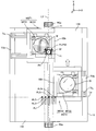
도 1은 일 실시예의 노광 장치의 구성을 개략적으로 도시하는 도면,
도 2는 도 1의 노광 장치의 평면도,
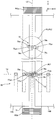
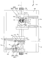
도 3의 (A)는 +Y측으로부터 보았을 때의 도 1의 노광 장치의 측면도, 도 3의 (B)는 -X측에서 보았을 때의 도 1의 노광 장치의 측면도(부분 단면도),
도 4의 (A)는 노광 장치를 구비한 웨이퍼 스테이지(WST1)의 평면도, 도 4의 (B)는 도 4의 (A)의 선 B-B를 따라 취한 단면의 단부도(end view), 도 4의 (C)는 도 4의 (A)의 선 C-C를 따라 취한 단면의 단부도,
도 5는 미동 스테이지 위치 측정 시스템의 구성을 도시하는 도면,
도 6은 도 1의 노광 장치가 구비한 주 제어기(main controller)의 입출력 관계를 설명하기 위해 사용되는 블록 다이어그램,
도 7은 웨이퍼 스테이지(WST1) 상에 탑재된 웨이퍼에 대해 노광이 수행되고 웨이퍼 스테이지(WST2) 상에서 웨이퍼 교환이 수행되는 상태를 도시하는 도면,
도 8은 웨이퍼 스테이지(WST1) 상에 탑재된 웨이퍼에 대해 노광이 수행되고 웨이퍼 스테이지(WST2) 상에 탑재된 웨이퍼에 대해 웨이퍼 정렬이 수행되는 상태를 도시하는 도면,
도 9는 웨이퍼 스테이지(WST2)가 정반(14B) 상에서 우측 스크럼(scrum) 위치를 향해 이동하는 상태를 도시하는 도면,
도 10은 웨이퍼 스테이지(WST1) 및 웨이퍼 스테이지(WST2)의 스크럼 위치로의 이동이 완료된 상태를 도시하는 도면,
도 11은 웨이퍼 스테이지(WST2) 상에 탑재된 웨이퍼에 대해 노광이 수행되고 웨이퍼 스테이지(WST1) 상에서 웨이퍼 교환이 수행되는 상태를 도시하는 도면,
도 12의 (A)는 변형예에 관련된 웨이퍼 스테이지를 도시하는 평면도, 도 12의 (B)는 도 12의 (A)의 B-B선을 따라 취한 단면도.1 is a view schematically showing a configuration of an exposure apparatus according to an embodiment,
Fig. 2 is a plan view of the exposure apparatus of Fig. 1,
FIG. 3A is a side view of the exposure apparatus of FIG. 1 viewed from the + Y side, FIG. 3B is a side view (partial cross-sectional view) of the exposure apparatus of FIG.
4A is a plan view of the wafer stage WST1 equipped with an exposure apparatus, FIG. 4B is an end view of a section taken along the line BB in FIG. 4A, FIG. (C) of Fig. 4 is an end view of a section taken along the line CC of Fig. 4 (A)
5 is a diagram showing a configuration of a fine movement stage position measurement system,
FIG. 6 is a block diagram used to explain the input / output relationship of the main controller of the exposure apparatus of FIG. 1,
7 is a view showing a state in which exposure is performed on a wafer mounted on the wafer stage WST1 and wafer exchange is performed on the wafer stage WST2,
8 is a view showing a state in which wafer alignment is performed on wafers mounted on the wafer stage WST1 and on which the exposure is performed and mounted on the wafer stage WST2,
9 is a diagram showing a state in which the wafer stage WST2 moves on the
10 is a view showing a state in which movement of the wafer stage WST1 and the wafer stage WST2 to the position of the scrum is completed,
11 is a view showing a state in which exposure is performed on a wafer mounted on the wafer stage WST2 and wafer exchange is performed on the wafer stage WST1,
FIG. 12A is a plan view showing a wafer stage according to a modified example, and FIG. 12B is a cross-sectional view taken along line BB in FIG. 12A.
본 발명의 일 실시예가 도 1 내지 도 11을 참조하여 아래에 설명된다.One embodiment of the present invention is described below with reference to Figs.
도 1은 이 실시예에 관련된 노광 장치(100)의 구성을 개략적으로 도시하고 있다. 노광 장치(100)는 이른바 스캐너(scanner)인 스텝-앤드-스캔 방식의 투영 노광 장치이다. 후술되는 바와 같이, 투영 광학 시스템(PL)이 이 실시예에서 제공되며, 아래의 설명에 있어서, 투영 광학 시스템(PL)의 광축(AX)에 평행한 방향은 Z축 방향, Z축 방향에 직교하는 평면 내에서 레티클 및 웨이퍼가 상대적으로 스캐닝되는 방향은 Y축 방향, 그리고 Z축 및 Y축에 직교하는 방향은 X축 방향, 그리고 X축, Y축 및 Z축 주위의 회전(경사) 방향은 각각 θx, θy 및 θz 방향인 것으로 가정하여 설명이 제공된다.Fig. 1 schematically shows the configuration of an
도 1에 도시된 바와 같이, 노광 장치(100)는 베이스 보드(base board)(12) 상의 +Y측 단부 근방에 배치된 노광 스테이션(노광 처리 영역)(200), 베이스 보드(12) 상의 -Y측 단부 근방에 배치된 측정 스테이션(측정 처리 영역)(300), 2개의 웨이퍼 스테이지(WST1, WST2)를 포함하는 스테이지 장치(50), 및 이들의 제어 시스템 등을 구비한다. 도 1에서, 웨이퍼 스테이지(WST1)는 노광 스테이션(200) 내에 위치되고, 웨이퍼(W)는 웨이퍼 스테이지(WST1) 상에 유지된다. 그리고, 웨이퍼 스테이지(WST2)는 측정 스테이션(300) 내에 위치되고, 다른 웨이퍼(W)가 웨이퍼 스테이지(WST2) 상에 유지된다.1, the
노광 스테이션(200)은 조명 시스템(10), 레티클 스테이지(RST), 투영 유닛(PU), 국소 액침 장치(8) 등을 구비한다.The
조명 시스템(10)은, 예를 들어 미국 특허 출원 공개 제 2003/0025890 호 등에 개시된 바와 같이, 광-인티그레이터(optical integrator) 등을 포함하는 조도 균일화 광학 시스템, 및 레티클 블라인드 등(모두 도시되지 않음)을 갖는 조명 광학 시스템과, 광원을 포함한다. 조명 시스템(10)은 레티클(R) 상의, 레티클 블라인드(마스킹 시스템으로도 지칭됨)에 의해 한정된 슬릿 형상의 조명 영역(IAR)을, 조명광(노광광)(IL)에 의해 실질적으로 균일한 조도로 조명한다. 조명광(IL)으로서는, ArF 엑시머 레이저광(파장 : 193㎚)이 일례로서 사용된다.The
레티클 스테이지(RST) 상에는, 회로 패턴 등이 상부에 형성된 패턴면(도 1에서 하부면)을 갖는 레티클(R)이 예를 들어 진공 흡착에 의해 고정된다. 레티클 스테이지(RST)는, 예를 들어 리니어 모터 등을 포함하는 레티클 스테이지 구동 시스템(11)(도 1에는 도시되지 않음, 도 6 참조)에 의해, 스캐닝 방향(도 1의 지면의 횡방향인 Y축 방향임)으로 사전결정된 스캐닝 속도, 사전결정된 스트로크로 구동될 수 있으며, 또한 X축 방향으로 미세하게 구동될 수 있다.On the reticle stage RST, a reticle R having a pattern surface (lower surface in Fig. 1) on which a circuit pattern or the like is formed is fixed by, for example, vacuum adsorption. The reticle stage RST is moved in the scanning direction (the Y direction in the lateral direction of the sheet of Fig. 1) by a reticle stage driving system 11 (not shown in Fig. 1, see Fig. 6) Axis direction), a predetermined stroke, and finely driven in the X-axis direction.
레티클 스테이지(RST)의 XY 평면 내의 위치 정보(θz 방향의 회전 정보를 포함함)는 레티클 스테이지(RST)에 고정된 이동형 미러(15)(실제로는, Y축 방향에 직교하는 반사면을 갖는 Y 이동형 미러(또는 역반사기(retroreflector)) 및 X축 방향에 직교하는 반사면을 갖는 X 이동형 미러가 배열됨)를 통해 레티클 레이저 간섭계(이하에서, "레티클 간섭계"로 지칭됨)(13)에 의해, 예를 들어 대략 0.25㎚의 분해능으로 상시 검출된다. 레티클 간섭계(13)의 측정값은 주 제어기(20)(도 1에는 도시되지 않음, 도 6 참조)로 전송된다. 또한, 예를 들어 PCT 국제 공개 제 2007/083758 호(미국 특허 출원 공개 제 2007/0288121 호에 대응) 등에 개시된 바와 같이, 레티클 스테이지(RST)의 위치 정보는 인코더 시스템에 의해 측정될 수 있다.Position information (including rotation information in the? Z direction) of the reticle stage RST in the XY plane is converted into a moving
레티클 스테이지(RST)의 상방에는, 예를 들어 미국 특허 제 5,646,413 호에 상세하게 개시된 바와 같이, 각각이 CCD와 같은 촬상 디바이스를 갖고 정렬 조명광으로서 노광 파장을 갖는 광(이 실시예에서, 조명광(IL))을 사용하는 이미지 처리 방식에 의한 한쌍의 레티클 정렬 시스템(RA1, RA2)이 배치된다(도 1에서, 레티클 정렬 시스템(RA2)은 지면의 깊이 방향으로 레티클 정렬 시스템(RA1) 뒤에 가려져 있음). 주 제어기(20)는, 측정 플레이트가 투영 광학 시스템(PL)의 바로 아래에 위치된 상태에서, 투영 광학 시스템(PL)을 통해, 레티클(R) 상에 형성된 한쌍의 레티클 정렬 마크(도시 생략됨)의 투영 이미지와, 이 레티클 정렬 마크에 대응하는, 미동 스테이지(WFS1)(또는 WFS2) 상의 후술되는 측정 플레이트 상의 한쌍의 제 1 기준 마크를 검출하고, 한쌍의 레티클 정렬 시스템(RA1, RA2)은 주 제어기(20)에 의해 수행된 그러한 검출에 따라 투영 광학 시스템(PL)에 의한 레티클(R)의 패턴의 투영 영역의 중심과 측정 플레이트 상의 기준 위치, 즉 한쌍의 제 1 기준 마크의 중심 사이의 위치 관계를 검출하기 위해 사용된다. 레티클 정렬 시스템(RA1, RA2)의 검출 신호는 도시되지 않은 신호 처리 시스템을 통해 주 제어기(20)(도 6 참조)에 공급된다. 또한, 레티클 정렬 시스템(RA1, RA2)은 배열될 필요가 없다. 그러한 경우에, 예를 들어 미국 특허 출원 공개 제 2002/0041377 호 등에 개시된 바와 같이, 후술되는 미동 스테이지에 배열된 광투과부(광검출부)를 갖는 검출 시스템이 레티클 정렬 마크의 투영 이미지를 검출하도록 설치되는 것이 바람직하다.Above the reticle stage RST, for example, as described in detail in U.S. Patent No. 5,646,413, light having an imaging device such as a CCD and having an exposure wavelength as alignment illumination light (in this embodiment, illumination light IL )), a pair of reticle alignment system (RA 1, RA 2) by image processing methods are arranged to use (in FIG. 1, a reticle alignment system (RA 2) has a depth in the plane of the reticle alignment system (RA 1) Behind). The
투영 유닛(PU)은 도 1의 레티클 스테이지(RST)의 하방에 배치된다. 투영 유닛(PU)은, 투영 유닛(PU)의 외주에 고정된 플랜지부(FLG)를 통해, 도시되지 않은 지지 부재에 의해 수평으로 지지되는 메인 프레임(계측 프레임(metrology frame)으로도 지칭됨)(BD)에 의해 지지된다. 메인 프레임(BD)은 지지 부재에 방진(vibration isolating) 장치 등을 배열함으로써 외부로부터의 진동이 메인 프레임으로 전달되지 않거나, 메인 프레임이 외부로 진동을 전달하지 않도록 구성될 수 있다. 투영 유닛(PU)은 경통(40) 및 경통(40) 내에 유지되는 투영 광학 시스템(PL)을 포함한다. 투영 광학 시스템(PL)으로서, 예를 들어 Z축 방향에 평행한 광축(AX)을 따라 배치되는 복수의 광학 소자(렌즈 소자)로 구성되는 굴절 광학 시스템이 사용된다. 투영 광학 시스템(PL)은 예를 들어 양측 텔레센트릭(both-side telecentric)형이고, 사전결정된 투영 배율(예를 들어, 1/4배, 1/5배, 1/8배 등)을 갖는다. 따라서, 레티클(R) 상의 조명 영역(IAR)이 조명 시스템(10)으로부터의 조명광(IL)으로 조명될 때, 조명광(IL)은 패턴면이 투영 광학 시스템(PL)의 제 1 평면(물체 평면)과 실질적으로 일치하여 배치되는 레티클(R)을 통과한다. 이어서, 조명 영역(IAR) 내의 레티클(R)의 회로 패턴의 축소 이미지(회로 패턴의 일부의 축소 이미지)가, 투영 광학 시스템(PL)(투영 유닛(PU))을 통해, 투영 광학 시스템(PL)의 제 2 평면(이미지 평면)측에 배치되고 표면이 레지스트(resist)(감응제(sensitive agent))로 코팅된, 웨이퍼(W) 상의 전술된 조명 영역(IAR)에 공역인(conjugate) 영역(이하에서, 노광 영역으로도 지칭됨)(IA)에 형성된다. 이어서, 레티클 스테이지(RST) 및 웨이퍼 스테이지(WST1)(또는 WST2)의 동기 구동에 의해, 레티클(R)을 조명 영역(IAR)(조명광(IL))에 대해서 스캐닝 방향(Y축 방향)으로 이동시킴으로써 그리고 또한 웨이퍼(W)를 노광 영역(IA)(조명광(IL))에 대해서 스캐닝 방향(Y축 방향)으로 이동시킴으로써, 웨이퍼(W) 상의 1개의 쇼트 영역(shot area)(구획 영역)의 스캐닝 노광이 수행된다. 따라서, 레티클(R)의 패턴이 쇼트 영역 상으로 전사된다. 더 구체적으로, 이 실시예에서, 레티클(R)의 패턴은 조명 시스템(10) 및 투영 광학 시스템(PL)에 의해 웨이퍼(W) 상에 생성되며, 이 패턴은 조명광(IL)에 의한 웨이퍼(W) 상의 감응층(레지스트층)의 노광에 의해 웨이퍼(W) 상에 형성된다. 이 경우에, 투영 유닛(PU)은 메인 프레임(BD)에 의해 유지되고, 이 실시예에서, 메인 프레임(BD)은 각각 방진 기구를 통해 (바닥면과 같은) 설치면 상에 배치된 복수(예를 들어, 3개 또는 4개)의 지지 부재에 의해 실질적으로 수평으로 지지된다. 또한, 방진 기구는 지지 부재들의 각각과 메인 프레임(BD) 사이에 배치될 수 있다. 또한, 예를 들어 PCT 국제 공개 제 2006/038952 호에 개시된 바와 같이, 메인 프레임(BD)(투영 유닛(PU))은 투영 유닛(PU) 또는 레티클 베이스 등의 상방에 배치된 메인 프레임 부재(도시되지 않음)에 의해 현수 방식으로 지지될 수 있다.The projection unit PU is disposed below the reticle stage RST in Fig. The projection unit PU includes a main frame (also referred to as a metrology frame) supported horizontally by a support member (not shown) through a flange portion FLG fixed to the periphery of the projection unit PU, (BD). The main frame BD may be configured such that a vibration isolating device or the like is arranged on the supporting member so that external vibration is not transmitted to the main frame or that the main frame does not transmit vibration to the outside. The projection unit PU includes a projection optical system PL held in a
국소 액침 장치(8)는 액체 공급 장치(5), 액체 회수 장치(6)(도 1에는 모두 도시되지 않음, 도 6 참조), 및 노즐 유닛(32) 등을 포함한다. 도 1에 도시된 바와 같이, 노즐 유닛(32)은, 이 경우에 렌즈(이하에서, "팁 렌즈(tip lens)"로도 지칭됨)(191)인, 투영 광학 시스템(PL)을 구성하는 이미지 평면측(웨이퍼(W)측)에 가장 근접한 광학 소자를 유지하는 경통(40)의 하단부의 주위를 둘러싸도록, 도시되지 않은 지지 부재를 통해, 투영 유닛(PU) 등을 지지하는 메인 프레임(BD)에 의해 현수 방식으로 지지된다. 노즐 유닛(32)은 액체(Lq)의 공급 개구 및 회수 개구와, 웨이퍼(W)가 대향하도록 배치되고 회수 개구가 배열되는 하부면과, 액체 공급관(31A) 및 액체 회수관(31B)(도 1에는 모두 도시되지 않음, 도 2 참조)에 각각 접속된 공급 유동 채널 및 회수 유동 채널을 구비한다. 공급관(도시되지 않음)의 일단부는 액체 공급관(31A)에 접속되는 한편, 공급관의 타단부는 액체 공급 장치(5)에 접속되며, 회수관(도시되지 않음)의 일단부는 액체 회수관(31B)에 접속되는 한편, 회수관의 타단부는 액체 회수 장치(6)에 접속된다.The local
이 실시예에서, 주 제어기(20)는 팁 렌즈(191)와 웨이퍼(W) 사이의 공간에 액체를 공급하도록 액체 공급 장치(5)(도 6 참조)를 제어하고, 또한 팁 렌즈(191)와 웨이퍼(W) 사이의 공간으로부터 액체를 회수하도록 액체 회수 장치(6)(도 6 참조)를 제어한다. 이러한 작동시, 주 제어기(20)는 팁 렌즈(191)와 웨이퍼(W) 사이의 공간에 일정량의 액체(Lq)(도 1 참조)를 유지하는 동시에 이 공간 내의 액체를 끊임없이 교체하기 위해 공급되는 액체의 양과 회수되는 액체의 양을 제어한다. 이 실시예에서, 전술된 액체로서, ArF 엑시머 레이저광(193㎚의 파장을 갖는 광)을 투과시키는 순수(pure water)(굴절률 n≒1.44)가 사용될 것이다.In this embodiment, the
측정 스테이션(300)은 메인 프레임(BD)에 배열된 정렬 장치(99)를 구비한다. 정렬 장치(99)는, 예를 들어 미국 특허 출원 공개 제 2008/0088843 호 등에 개시된 바와 같이, 도 2에 도시된 5개의 정렬 시스템(AL1, AL21 내지 AL24)을 포함한다. 더 구체적으로, 도 2에 도시된 바와 같이, 투영 유닛(PU)의 중심(투영 광학 시스템(PL)의 광축(AX)임, 그리고 이 실시예에서, 전술된 노광 영역(IA)의 중심과도 일치함)을 통과하고 Y축에 평행한 직선(이하에서, 기준축으로 지칭됨)(LV) 상에서, 광축(AX)으로부터 -Y측에 사전결정된 거리만큼 이격된 위치에 검출 중심이 위치되는 상태로 1차 정렬 시스템(AL1)이 배치된다. 1차 정렬 시스템(AL1)을 사이에 두고서 X축 방향의 일측과 타측에는, 검출 중심이 기준축(LV)에 대해서 실질적으로 대칭으로 배치되는 2차 정렬 시스템(AL21, AL22와, AL23, AL24)이 각각 배열된다. 더 구체적으로, 5개의 정렬 시스템(AL1, AL21 내지 AL24)의 검출 중심은 1차 정렬 시스템(AL1)의 검출 중심에서 기준축(LV)과 수직으로 교차하고 X축에 평행한 직선(이하에서, 기준축으로 지칭됨)(La)을 따라 배치된다. 5개의 정렬 시스템(AL1, AL21 내지 AL24) 및 이들 정렬 시스템을 유지하는 유지 장치(슬라이더(slider))를 포함하는 구성이 도 1에 정렬 장치(99)로서 도시되어 있음에 유의한다. 예를 들어 미국 특허 출원 공개 제 2009/0233234 호 등에 개시된 바와 같이, 2차 정렬 시스템(AL21 내지 AL24)은 이동형 슬라이더를 통해 메인 프레임(BD)의 하부면에 고정되고(도 1 참조), 2차 정렬 시스템의 검출 영역의 상대 위치가 도시되지 않은 구동 기구에 의해 적어도 X축 방향에서 조정가능하다.The measuring
이 실시예에서, 각각의 정렬 시스템(AL1, AL21 내지 AL24)으로서, 예를 들어 이미지 처리 방식의 FIA(Field Image Alignment) 시스템이 사용된다. 정렬 시스템(AL1, AL21 내지 AL24)의 구성은 예를 들어 PCT 국제 공개 제 2008/056735 호 등에 상세하게 개시되어 있다. 정렬 시스템(AL1, AL21 내지 AL24)의 각각으로부터의 촬상 신호는 도시되지 않은 신호 처리 시스템을 통해 주 제어기(20)(도 6 참조)에 공급된다.In this embodiment, as each of the alignment systems AL1, AL2 1 to AL2 4 , for example, an image processing type FIA (Field Image Alignment) system is used. The arrangement of the alignment systems (AL1, AL2 1 to AL2 4 ) is disclosed in detail, for example, in PCT International Publication No. 2008/056735. The imaging signals from each of the alignment systems AL1, AL2 1 to AL2 4 are supplied to the main controller 20 (see Fig. 6) through a signal processing system not shown.
노광 장치(100)는, 로딩 위치가 도시되지 않았지만, 웨이퍼 스테이지(WST1)에 대해서 웨이퍼의 반송 작업이 수행되는 제 1 로딩 위치, 및 웨이퍼 스테이지(WST2)에 대해서 웨이퍼의 반송 작업이 수행되는 제 2 로딩 위치를 갖는 것에 유의한다. 이 실시예의 경우, 제 1 로딩 위치는 정반(14A)측에 배열되고, 제 2 로딩 위치는 정반(14B)측에 배열된다.Although the loading position is not shown in the drawing, the
도 1에 도시된 바와 같이, 스테이지 장치(50)는 베이스 보드(12), 베이스 보드(12)의 상방에 배치되는 한쌍의 정반(14A, 14B)(도 1에서, 정반(14B)은 지면의 깊이 방향으로 정반(14A) 뒤에 가려져 있음), 한쌍의 정반(14A, 14B)의 상부면에 의해 형성된 XY 평면에 평행한 가이드면 상에서 이동하는 2개의 웨이퍼 스테이지(WST1, WST2), 배관/배선 시스템(이하에서, 편의를 위해 튜브로 지칭됨)(Ta2, Tb2)(도 1에 도시되지 않음, 도 2 및 도 3의 (A) 참조)을 통해 웨이퍼 스테이지(WST1, WST2)에 각각 접속된 튜브 캐리어(TCa, TCb)(튜브 캐리어(TCb)는 도 1에 도시되지 않음, 도 2 및 도 3의 (A)와 같은 도면을 참조), 웨이퍼 스테이지(WST1, WST2)의 위치 정보를 측정하는 측정 시스템 등을 구비한다. 다양한 유형의 센서 및 모터와 같은 액추에이터를 위한 전력, 액추에이터에 대한 온도 조절용 냉각제, 공기 베어링을 위한 가압 공기 등이 튜브(Ta2, Tb2)를 통해 외부로부터 웨이퍼 스테이지(WST1, WST2)로 각각 공급된다. 이하의 설명에서, 전력, 온도 조절용 냉각제, 가압 공기 등은 또한 총괄하여 용력(power usage)으로 지칭됨에 유의한다. 진공 흡인력이 필요한 경우에, 진공을 위한 힘(음압)도 또한 용력에 포함된다.1, the
베이스 보드(12)는 평판 형상의 외형을 갖는 부재로 구성되고, 도 1에 도시된 바와 같이 바닥면(102) 상에 방진 기구(도시 생략됨)를 통해 실질적으로 수평으로(XY 평면에 평행하게) 지지된다. 베이스 보드(12)의 상부면의 X축 방향의 중앙부에는, 도 3의 (A)에 도시된 바와 같이, Y축에 평행한 방향으로 연장되는 오목부(recessed section)(12a)(오목 홈)가 형성된다. (이 경우에, 오목부(12a)가 형성된 부분을 제외하고) 베이스 보드(12)의 상부면측에는, XY 2차원 방향을 행방향 및 열방향으로 하여 매트릭스(matrix) 형상으로 배치된 복수의 코일을 포함하는 코일 유닛(CU)이 수용된다. 또한, 도 3의 (A) 및 도 3의 (B)에 도시된 바와 같이, 베이스 보드(12)의 오목부(12a)의 내측 바닥면의 하방에, XY 2차원 평면을 행방향 및 열방향으로 하여 매트릭스 형상으로 배치된 복수의 코일을 포함하는 코일 유닛(18)이 수용된다. 코일 유닛(18)을 구성하는 복수의 코일의 각각에 공급되는 전류의 크기 및 방향은 주 제어기(20)(도 6 참조)에 의해 제어된다.The
도 2에 도시된 바와 같이, 정반(14A, 14B)은 각각 평면에서 보았을 때(위에서 보았을 때) 길이방향을 Y축 방향으로 하는 직사각형의 판형상 부재로 구성되고, 기준축(LV)의 -X측 및 +X측에 각각 배치된다. 정반(14A) 및 정반(14B)은 기준축(LV)에 대해서 대칭으로, X축 방향에서 매우 좁은 갭(gap)을 사이에 두고서 배치된다. 상부면이 매우 높은 평탄도를 갖도록 정반(14A, 14B)의 각각의 상부면(+Z측 표면)을 마무리함으로써, 웨이퍼 스테이지(WST1, WST2)의 각각이 XY 평면을 따라 이동할 때 사용되는 Z축 방향에 대한 가이드면으로서 상부면이 기능을 하게 하는 것이 가능하다. 대안적으로, 후술되는 평면 모터에 의해 웨이퍼 스테이지(WST1, WST2)에 Z 방향의 힘이 작용되게 하여 웨이퍼 스테이지(WST1, WST2)를 정반(14A, 14B) 위로 자기 부상시키는 구성이 채용될 수 있다. 이 실시예의 경우, 평면 모터를 사용하는 구성이 채용되고 기체 정압 베어링이 사용되지 않으며, 따라서 정반(14A, 14B)의 상부면의 평탄도는 상기의 설명에서와 같이 그렇게 높을 필요가 없다.As shown in FIG. 2, the
도 3에 도시된 바와 같이, 정반(14A, 14B)은 도시되지 않은 공기 베어링(또는 구름 베어링)을 통해 베이스 보드(12)의 오목부(12a)의 양 측부의 상부면(12b) 상에 지지된다.3, the
정반(14A, 14B)은 가이드면이 그의 상부면 상에 형성된 비교적 얇은 판형상을 각각 갖는 제 1 부분(14A1, 14B1), 및 비교적 두꺼운 판형상을 각각 갖고 X축 방향에서 짧으며 제 1 부분(14A1, 14B1)의 하부면에 각각 일체적으로 고정된 제 2 부분(14A2, 14B2)을 각각 갖는다. 정반(14A)의 제 1 부분(14A1)의 +X측의 단부는 제 2 부분(14A2)의 +X측의 단부면으로부터 +X측으로 약간 돌출되고, 정반(14B)의 제 1 부분(14B1)의 -X측의 단부는 제 2 부분(14B2)의 -X측의 단부면으로부터 -X측으로 약간 돌출된다. 그러나, 구성은 전술된 것으로 한정되지 않으며, 돌출부가 배열되지 않는 구성이 채용될 수 있다.The
제 1 부분(14A1, 14B1)의 각각의 내부에는, XY 2차원 방향을 행방향 및 열방향으로 하여 매트릭스 형상으로 배치된 복수의 코일을 포함하는 코일 유닛(도시 생략됨)이 수용된다. 각각의 코일 유닛을 구성하는 복수의 코일의 각각에 공급되는 전류의 크기 및 방향은 주 제어기(20)(도 6 참조)에 의해 제어된다.In each of the
정반(14A)의 제 2 부분(14A2)의 내부(바닥부)에는, XY 2차원 방향을 행방향 및 열방향으로 하여 매트릭스 형상으로 배치된 복수의 영구 자석(및 도시되지 않은 요크(yoke))으로 구성되는 자석 유닛(MUa)이 베이스 보드(12)의 상부면측에 수용된 코일 유닛(CU)에 대응하도록 수용된다. 자석 유닛(MUa)은 베이스 보드(12)의 코일 유닛(CU)과 함께, 예를 들어 미국 특허 출원 공개 제 2003/0085676 호 등에 개시된 전자기력(로렌츠 힘) 구동 방식의 평면 모터로 구성되는 정반 구동 시스템(60A)(도 6 참조)을 구성한다. 정반 구동 시스템(60A)은 XY 평면 내의 3 자유도 방향(X, Y, θz)으로 정반(14A)을 구동시키는 구동력을 발생시킨다.A plurality of permanent magnets (and an unillustrated yoke) arranged in a matrix form in the row direction and the column direction in the XY two-dimensional direction are formed in the interior (bottom portion) of the
유사하게, 정반(14B)의 제 2 부분(14B2)의 내부(바닥부)에는, 복수의 영구 자석(및 도시되지 않은 요크)으로 구성되는 자석 유닛(MUb)이 수용되고, 이 자석 유닛(MUb)은 베이스 보드(12)의 코일 유닛(CU)과 함께, XY 평면 내의 3 자유도 방향으로 정반(14B)을 구동시키는 평면 모터로 구성되는 정반 구동 시스템(60B)(도 6 참조)을 구성한다. 또한, 정반 구동 시스템(60A, 60B)의 각각을 구성하는 평면 모터의 코일 유닛 및 자석 유닛의 배치는 전술된 경우(이동 자석 유형)와 반대(베이스 보드측에 자석 유닛을, 그리고 정반측에 코일 유닛을 갖는 이동 코일 유형)일 수 있다.Similarly, the second portion of the surface plate (14B) inside the (14B 2) (bottom), the magnet unit (MUb) which is composed of a plurality of permanent magnets (and not shown York) is received, the magnet unit ( MUb constitute a planar driving system 60B (see Fig. 6) constituted by a planar motor that drives the
3 자유도 방향의 정반(14A, 14B)의 위치 정보는, 예를 들어 인코더 시스템을 각각 포함하는 제 1 정반 위치 측정 시스템(69A) 및 제 2 정반 위치 측정 시스템(69B)(도 6 참조)에 의해 각각 서로 독립적으로 획득(측정)된다. 제 1 정반 위치 측정 시스템(69A) 및 제 2 정반 위치 측정 시스템(69B)의 각각의 출력은 주 제어기(20)(도 6 참조)에 공급되고, 주 제어기(20)는 정반 위치 측정 시스템(69A, 69B)의 출력을 이용하여(출력에 기초하여), 정반 구동 시스템(60A, 60B)의 코일 유닛을 구성하는 각각의 코일에 공급되는 전류의 크기 및 방향을 제어하며, 이에 의해 XY 평면 내의 3 자유도 방향의 정반(14A, 14B)의 각각의 위치를 필요에 따라 제어한다. 주 제어기(20)는, 정반(14A, 14B)이 후술되는 카운터매스(countermass)로서 기능을 할 때, 기준 위치로부터의 정반(14A, 14B)의 이동 거리가 사전결정된 범위 내에 있도록, 정반(14A, 14B)을 정반의 기준 위치로 복귀시키기 위해, 정반 위치 측정 시스템(69A, 69B)의 출력을 이용하여(출력에 기초하여), 정반 구동 시스템(60A, 60B)을 통해 정반(14A, 14B)을 구동시킨다. 더 구체적으로, 정반 구동 시스템(60A, 60B)은 트림 모터(trim motor)로서 사용된다.Position information of the
제 1 정반 위치 측정 시스템(69A) 및 제 2 정반 위치 측정 시스템(69B)의 구성은 특별히 제한되지 않지만, 예를 들어 제 2 부분(14A2, 14B2) 각각의 하부면 상에 배치된 스케일(예를 들어, 2차원 격자(grating))에 측정 빔을 조사하고 이 조사에 의해 얻어진 반사광(2차원 격자로부터의 회절광)을 이용함으로써 XY 평면 내의 3 자유도 방향의 각각의 정반(14A, 14B)의 위치 정보를 획득(측정)하는 인코더 헤드가 베이스 보드(12)에 배치되는(또는 인코더 헤드가 제 2 부분(14A2, 14B2)에, 스케일이 베이스 보드(12)에 각각 배치됨) 인코더 시스템이 사용될 수 있다. 또한, 예를 들어 광학 간섭계 시스템, 또는 광학 간섭계 시스템과 인코더 시스템의 조합인 측정 시스템에 의해 정반(14A, 14B)의 위치 정보를 획득(측정)하는 것이 또한 가능하다.The configurations of the first and second table
웨이퍼 스테이지들 중 하나인 웨이퍼 스테이지(WST1)는 도 2에 도시된 바와 같이, 웨이퍼(W)를 유지하는 미동 스테이지(fine movement stage)(WFS1)(테이블로도 지칭됨), 및 미동 스테이지(WFS1)의 주위를 둘러싸는, 직사각형 프레임 형상을 갖는 조동 스테이지(coarse movement stage)(WCS1)를 구비한다. 웨이퍼 스테이지들 중 다른 것인 웨이퍼 스테이지(WST2)는, 도 2에 도시된 바와 같이, 웨이퍼(W)를 유지하는 미동 스테이지(WFS2), 및 미동 스테이지(WFS2)의 주위를 둘러싸는, 직사각형 프레임 형상을 갖는 조동 스테이지(WCS2)를 구비한다. 도 2로부터 명백한 바와 같이, 웨이퍼 스테이지(WST2)는, 웨이퍼 스테이지(WST2)가 웨이퍼 스테이지(WST1)에 대해서 좌우가 반대인 상태로 배치된 점을 제외하고, 구동 시스템, 위치 측정 시스템 등을 포함한 구성이 웨이퍼 스테이지(WST1)와 완전히 동일하다. 따라서, 하기의 설명에서, 웨이퍼 스테이지(WST1)를 대표적으로 중점을 두어 설명하며, 웨이퍼 스테이지(WST2)는 특별히 설명이 필요한 경우에만 설명된다.The wafer stage WST1, which is one of the wafer stages, includes a fine movement stage WFS1 (also referred to as a table) for holding the wafer W, and a fine movement stage WFS1 And a coarse movement stage WCS1 having a rectangular frame shape. As shown in Fig. 2, the wafer stage WST2, which is another one of the wafer stages, includes a fine movement stage WFS2 for holding the wafer W and a rectangular frame shape WFS2 surrounding the fine movement stage WFS2 And a coarse stage WCS2. 2, the wafer stage WST2 has a structure including a drive system, a position measurement system, and the like, except that the wafer stage WST2 is disposed opposite to the wafer stage WST1 Is exactly the same as the wafer stage WST1. Therefore, in the following description, the wafer stage WST1 will be described with an emphasis as an example, and the wafer stage WST2 will be described only when a special explanation is required.
도 4의 (A)에 도시된 바와 같이, 조동 스테이지(WCS1)는 서로 평행하게 배치되고, Y축 방향으로 이격되어 있으며, 길이방향을 X축 방향으로 하는 직육면체 부재로 각각 구성되는 한쌍의 조동 슬라이더부(90a, 90b)와; 길이방향을 Y축 방향으로 하는 직육면체 부재로 각각 구성되고, Y축 방향의 일단부 및 타단부와 한쌍의 조동 슬라이더부(90a, 90b)를 연결하는 한쌍의 연결 부재(92a, 92b)를 갖는다. 더 구체적으로, 조동 스테이지(WCS1)는 그의 중앙부에 Z축 방향으로 관통하는 직사각형 개구부를 갖는 직사각형 프레임 형상으로 형성된다.As shown in Fig. 4A, the coarse movement stages WCS1 are arranged parallel to each other, spaced apart in the Y-axis direction, and constituted by a pair of
조동 슬라이더부(90a, 90b)의 내부(바닥부)에는, 도 4의 (B) 및 도 4의 (C)에 도시된 바와 같이, 자석 유닛(96a, 96b)이 각각 수용된다. 자석 유닛(96a, 96b)은 정반(14A, 14B)의 제 1 부분(14A1, 14B1)의 내부에 수용된 코일 유닛에 각각 대응하며, XY 2차원 방향을 행방향 및 열방향으로 하여 매트릭스 형상으로 배치된 복수의 자석으로 각각 구성된다. 자석 유닛(96a 및 96b)은, 정반(14A 및 14B)의 코일 유닛과 함께, 예를 들어 미국 특허 출원 공개 제 2003/0085676 호 등에 개시되는, 조동 스테이지(WCS1)에 대해서 6 자유도 방향으로 구동력을 발생시킬 수 있는 전자기력(로렌츠 힘) 구동 방식의 평면 모터로 구성되는 조동 스테이지 구동 시스템(62A)(도 6 참조)을 구성한다. 또한, 이와 유사하게, 웨이퍼 스테이지(WST2)의 조동 스테이지(WCS2)(도 2 참조) 및 정반(14A, 14B)의 코일 유닛은 평면 모터로 구성되는 조동 스테이지 구동 시스템(62B)(도 6 참조)을 구성한다. 이 경우, Z축 방향의 힘이 조동 스테이지(WCS1)(또는 WCS2)에 작용하며, 이 조동 스테이지는 정반(14A, 14B) 위로 자기 부상된다. 따라서, 비교적 높은 기계가공 정밀도가 요구되는 기체 정압 베어링을 사용할 필요가 없고, 따라서 정반(14A, 14B)의 상부면의 평탄도를 증가시킬 필요가 없게 된다.
또한, 이 실시예의 조동 스테이지(WCS1, WCS2) 각각은 조동 슬라이더부(90a, 90b)만이 평면 모터의 자석 유닛을 갖는 구성을 갖지만, 이는 한정하고자 하는 것은 아니며, 자석 유닛은 연결 부재(92a, 92b)에도 배치될 수 있다. 또한, 조동 스테이지(WCS1, WCS2)를 구동시키는 액추에이터는 전자기력(로렌츠 힘) 구동 방식의 평면 모터로 한정되지 않으며, 예를 들어 가변 자기저항 구동 방식의 평면 모터 등이 사용될 수 있다. 또한, 조동 스테이지(WCS1, WCS2)의 구동 방향은 6 자유도 방향으로 한정되지 않으며, 예를 들어 XY 평면 내의 3 자유도 방향(X, Y, θz)만일 수 있다. 이 경우, 조동 스테이지(WCS1, WCS2)는 예를 들어 기체 정압 베어링(예를 들어, 공기 베어링)을 이용하여 정반(14A, 14B) 위로 부상되어야 한다. 또한, 이 실시예에서, 이동 자석 유형의 평면 모터가 각각의 조동 스테이지 구동 시스템(62A, 62B)으로서 사용되지만, 이는 한정하고자 하는 것은 아니며, 자석 유닛이 정반에 배치되고 코일 유닛이 조동 스테이지에 배치되는 이동 코일 유형의 평면 모터가 또한 사용될 수 있다.Each of the coarse stages WCS1 and WCS2 of this embodiment has a configuration in which only the
조동 슬라이더부(90a)의 -Y측의 측면과 조동 슬라이더부(90b)의 +Y측의 측면 상에는, 미동 스테이지(WFS1)가 미세하게 구동될 때 사용되는 가이드로서 기능을 하는 가이드 부재(94a, 94b)가 각각 고정된다. 도 4의 (B)에 도시된 바와 같이, 가이드 부재(94a)는 X축 방향으로 연장되어 배열되는 L자형 단면 형상을 갖는 부재로 구성되고, 그것의 하부면은 조동 슬라이더부(90a)의 하부면과 동일 평면 상에 배치된다. 가이드 부재(94b)는 가이드 부재(94a)에 대해서 좌우 대칭이지만 가이드 부재(94a)와 유사하게 구성 및 배치된다.On the side of the -Y side of the
가이드 부재(94a)의 내부(바닥면)에는, XY 2차원 방향을 행방향 및 열방향으로 하여 매트릭스 형상으로 배치된 복수의 코일을 각각 포함하는 한쌍의 코일 유닛(CUa, CUb)이 X축 방향에 관해 사전결정된 거리에 수용된다(도 4의 (A) 참조). 한편, 가이드 부재(94b)의 내부(바닥부)에는, XY 2차원 방향을 행방향 및 열방향으로 하여 매트릭스 형상으로 배치된 복수의 코일을 포함하는 하나의 코일 유닛(CUc)이 수용된다(도 4의 (A) 참조). 코일 유닛(CUa 내지 CUc)을 구성하는 코일들의 각각에 공급되는 전류의 크기 및 방향은 주 제어기(20)(도 6 참조)에 의해 제어된다.A pair of coil units CUa and CUb each including a plurality of coils arranged in a matrix with the XY two-dimensional direction as the row direction and the column direction are formed on the inside (bottom surface) of the
연결 부재(92a, 92b)는 중공형(hollow)으로 형성되며, 미동 스테이지(WFS1)에 용력을 공급하기 위해 사용되는 도시되지 않은 배관 부재, 배선 부재 등이 그 내부에 수용된다. 연결 부재(92a 및/또는 92b)의 내부에는, 다양한 유형의 광학 부재(예를 들어, 공간 이미지(aerial image) 계측기, 조도 불균일 계측기, 조도 모니터, 파면 수차 계측기 등)가 수용될 수 있다.The connecting
이 경우, 웨이퍼 스테이지(WST1)가 조동 스테이지 구동 시스템(62A)을 구성하는 평면 모터에 의해 정반(14A) 상에서 Y축 방향으로 가속/감속으로 구동될 때(예를 들어, 웨이퍼 스테이지(WST1)가 노광 스테이션(200)과 측정 스테이션(300) 사이를 이동할 때), 정반(14A)은 웨이퍼 스테이지(WST1)의 구동에 의한 반력의 작용으로 인해 이른바 작용 및 반작용의 법칙(운동량 보존의 법칙)에 따라 웨이퍼 스테이지(WST1)와 반대의 방향으로 구동된다. 또한, 정반 구동 시스템(60A)에 의해 Y축 방향에 관해 구동력을 발생시킴으로써 전술된 작용 및 반작용의 법칙이 적용되지 않는 상태를 만드는 것이 또한 가능하다.In this case, when the wafer stage WST1 is driven in the Y-axis direction by acceleration / deceleration on the
또한, 웨이퍼 스테이지(WST2)가 정반(14B) 상에서 Y축 방향으로 구동될 때, 정반(14B)도 또한 웨이퍼 스테이지(WST2)의 구동력의 반력의 작용으로 인해 이른바 작용 및 반작용의 법칙(운동량 보존의 법칙)에 따라 웨이퍼 스테이지(WST2)와 반대의 방향으로 구동된다. 더 구체적으로, 정반(14A, 14B)은 카운터매스로서 기능을 하며, 웨이퍼 스테이지(WST1, WST2) 및 정반(14A, 14B)의 전체로서 구성되는 시스템의 운동량은 보존되고, 중심의 이동은 발생하지 않는다. 따라서, Y축 방향의 웨이퍼 스테이지(WST1, WST2)의 이동으로 인해 정반(14A, 14B)에 작용하는 편하중과 같은 어떠한 장애도 발생하지 않는다. 또한, 웨이퍼 스테이지(WST2)에 관해서도, 정반 구동 시스템(60B)에 의해 Y축 방향에 관해서 구동력을 발생시킴으로써 전술된 작용 및 반작용의 법칙이 적용되지 않는 상태를 만드는 것이 가능하다.Further, when the wafer stage WST2 is driven in the Y-axis direction on the table 14B, the table 14B also has a so-called action and reaction rule (action of conservation of momentum) due to the action of the reaction force of the wafer stage WST2 The wafer stage WST2 is driven in the opposite direction to the wafer stage WST2. More specifically, the
또한, 웨이퍼 스테이지(WST1, WST2)의 X축 방향의 구동력의 반력의 작용에 의해, 정반(14A, 14B)은 카운터매스로서 기능을 한다.Further, by the action of the reaction force of the driving force in the X-axis direction of the wafer stages WST1 and WST2, the
도 4의 (A) 및 도 4의 (B)에 도시된 바와 같이, 미동 스테이지(WFS1)는 평면에서 보았을 때 직사각형 형상을 갖는 부재로 구성되는 본체부(80), 본체부(80)의 +Y측의 측면에 고정된 한쌍의 미동 슬라이더부(84a, 84b), 및 본체부(80)의 -Y측의 측면에 고정된 미동 슬라이더부(84c)를 구비한다.As shown in Figs. 4A and 4B, the fine movement stage WFS1 includes a
본체부(80)는 비교적 작은 열팽창 계수를 갖는 재료, 예를 들어 세라믹, 유리 등에 의해 형성되며, 본체부의 바닥면이 조동 스테이지(WCS1)의 바닥면과 동일 평면 상에 위치되는 상태로 비접촉 방식으로 조동 스테이지(WCS1)에 의해 지지된다. 본체부(80)는 경량화를 위해 중공형일 수 있다. 또한, 본체부(80)의 바닥면은 반드시 조동 스테이지(WCS1)의 바닥면과 동일 평면 상에 있을 필요는 없다.The
본체부(80)의 상부면의 중앙에는, 진공 흡착 등에 의해 웨이퍼(W)를 유지하는 웨이퍼 홀더(도시되지 않음)가 배치된다. 이 실시예에서, 웨이퍼(W)를 지지하는 복수의 지지부(핀 부재(pin member))가 예를 들어 환형 돌출부(림부) 내에 형성되는, 이른바 핀 척 방식의 웨이퍼 홀더가 사용되며, 하나의 면(정면(front surface))을 웨이퍼 탑재면으로 하는 웨이퍼 홀더는 다른 면(배면)측에 배열된, 후술되는 2차원 격자(RG) 등을 갖는다. 또한, 웨이퍼 홀더는 미동 스테이지(WFS1)(본체부(80))와 일체로 형성될 수 있거나, 예를 들어 정전 척 기구 또는 클램프 기구와 같은 유지 기구를 통해 탈착가능하도록 본체부(80)에 고정될 수 있다. 이 경우, 격자(RG)는 본체부(80)의 배면측에 배열될 것이다. 또한, 웨이퍼 홀더는 접착제 등에 의해 본체부(80)에 고정될 수 있다. 본체부(80)의 상부면 상에는, 도 4의 (A)에 도시된 바와 같이, 웨이퍼(W)(웨이퍼 홀더)보다 약간 큰 원형 개구가 중앙에 형성되고, 본체부(80)에 대응하는 직사각형 외형(윤곽)을 갖는 플레이트(발액(liquid-repellent) 플레이트)(82)가 웨이퍼 홀더(웨이퍼(W)의 탑재 영역)의 외측에 부착된다. 액체(Lq)에 대한 발액 처리가 플레이트(82)의 표면에 적용된다(발액면이 형성됨). 이 실시예에서, 플레이트(82)의 표면은 금속, 세라믹, 유리 등으로 구성된 기재(base material), 및 기재의 표면 상에 형성된 발액성 재료의 필름을 포함한다. 발액성 재료는 예를 들어 PFA(테트라 플루오로 에틸렌-퍼플루오로 알킬비닐 에테르 공중합체), PTFE(폴리 테트라 플루오로 에틸렌), 테프론(Teflon)(등록 상표) 등을 포함한다. 또한, 필름을 형성하는 재료는 아크릴계 수지 또는 실리콘계 수지일 수 있다. 또한, 플레이트(82) 전체가 PFA, PTFE, 테프론(등록 상표), 아크릴계 수지 및 실리콘계 수지 중 적어도 하나로 형성될 수 있다. 이 실시예에서, 액체(Lq)에 대한 플레이트(82)의 상부면의 접촉각은 예를 들어 90도 이상이다. 전술된 연결 부재(92b)의 표면 상에도, 유사한 발액 처리가 적용된다.At the center of the upper surface of the
플레이트(82)는 플레이트(82)의 표면 전체(또는 표면의 일부)가 웨이퍼(W)의 표면과 동일 평면 상에 있도록 본체부(80)의 상부면에 고정된다. 또한, 플레이트(82) 및 웨이퍼(W)의 표면은 전술된 연결 부재(92b)의 표면과 실질적으로 동일 평면 상에 위치된다. 또한, 플레이트(82)의 +Y측에 위치된 +X측의 코너 근방에는, 원형 개구가 형성되고, 이 개구 내에는, 측정 플레이트(FM1)가 웨이퍼(W)의 표면과 실질적으로 동일 평면 상에 있는 상태로 어떠한 갭도 개재됨이 없이 배치된다. 측정 플레이트(FM1)의 상부면 상에는, 한쌍의 레티클 정렬 시스템(RA1, RA2)(도 1 및 도 6 참조)에 의해 각각 검출되는 한쌍의 제 1 기준 마크, 및 1차 정렬 시스템(AL1)에 의해 검출되는 제 2 기준 마크(어떠한 마크도 도시되지 않음)가 형성된다. 웨이퍼 스테이지(WST2)의 미동 스테이지(WFS2)에는, 도 2에 도시된 바와 같이, 플레이트(82)의 +Y측에 위치된 -X측의 코너의 근방에, 측정 플레이트(FM1)와 유사한 측정 플레이트(FM2)가 웨이퍼(W)의 표면과 실질적으로 동일 평면 상에 있는 상태로 고정된다. 또한, 플레이트(82)를 미동 스테이지(WFS1)(본체부(80))에 부착시키는 대신에, 예를 들어 웨이퍼 홀더가 미동 스테이지(WFS1)와 일체로 형성되고, 미동 스테이지(WFS1)의 상부면의, 웨이퍼 홀더((측정 플레이트의 표면을 포함할 수 있는) 플레이트(82)와 동일한 영역)를 둘러싸는 주위 영역에 발액 처리가 적용되어 발액면이 형성되는 것이 또한 가능하다.The
미동 스테이지(WFS1)의 본체부(80)의 하부면의 중앙부에는, 도 4의 (B)에 도시된 바와 같이, 웨이퍼 홀더(웨이퍼(W)의 탑재 영역) 및 측정 플레이트(FM1)(또는 미동 스테이지(WFS2)의 경우 측정 플레이트(FM2))를 덮는 정도로 큰 사전결정된 얇은 판형상을 갖는 플레이트가 하부면이 다른 부분(주위 부분)과 실질적으로 동일 평면 상에 위치되는(플레이트의 하부면이 주위 부분 아래로 돌출되지 않음) 상태로 배치된다. 플레이트의 하나의 표면(상부면(또는 하부면)) 상에는, 2차원 격자(RG)(이하에서, 간단하게 격자(RG)로 지칭됨)가 형성된다. 격자(RG)는 주기 방향을 X축 방향으로 하는 반사형 회절 결자(X 회절 격자), 및 주기 방향을 Y축 방향으로 하는 반사형 회절 격자(Y 회절 격자)를 포함한다. 플레이트는 예를 들어 유리에 의해 형성되고, 격자(RG)는 예를 들어 138㎚ 내지 4㎛의 피치, 예를 들어 1㎛의 피치로 회절 격자의 눈금을 조각함으로써 생성된다. 또한, 격자(RG)는 또한 본체부(80)의 하부면 전체를 덮을 수 있다. 또한, 격자(RG)를 위해 사용되는 회절 격자의 유형은 홈 등이 기계적으로 형성되는 것으로 한정되지 않으며, 예를 들어 감광성 수지 상에 간섭 무늬를 노출시킴으로써 생성된 회절 격자가 또한 채용될 수 있다. 또한, 얇은 판형상을 갖는 플레이트의 구성은 반드시 전술된 것으로 한정되지 않는다.4B, a wafer holder (wafer W mounting area) and a measuring plate FM1 (or a fine positioning plate) are provided at the center of the lower surface of the
도 4의 (A)에 도시된 바와 같이, 한쌍의 미동 슬라이더부(84a, 84b)는 각각 평면에서 보았을 때 대략 정사각형 형상을 갖는 판형상 부재이며, 본체부(80)의 +Y측의 측면 상에, X축 방향에 관해 사전결정된 거리만큼 이격되어 배치된다. 미동 슬라이더부(84c)는 평면에서 보았을 때 X축 방향으로 기다란 직사각형 형상을 갖는 판형상 부재이며, 길이방향의 일단부 및 타단부가 미동 슬라이더부(84a, 84b)의 중심과 실질적으로 동일 직선상인 Y축에 평행한 직선 상에 위치되는 상태로 본체부(80)의 -Y측의 측면에 고정된다.As shown in Fig. 4 (A), the pair of
한쌍의 미동 슬라이더부(84a, 84b)는 전술된 가이드 부재(94a)에 의해 각각 지지되고, 미동 슬라이더부(84c)는 가이드 부재(94b)에 의해 지지된다. 더 구체적으로, 미동 스테이지(WFS)는 조동 스테이지(WCS)에 대해서 동일 직선상이 아닌 3개소에서 지지된다.The pair of fine
미동 슬라이더부(84a 내지 84c)의 내부에는, XY 2차원 방향을 행방향 및 열방향으로 하여 매트릭스 형상으로 배치된 복수의 영구 자석(및 도시되지 않은 요크)으로 각각 구성되는 자석 유닛(98a, 98b, 98c)이 조동 스테이지(WCS1)의 가이드부(94a, 94b)가 갖는 코일 유닛(CUa 내지 CUc)에 대응하도록 각각 수용된다. 자석 유닛(98a)은 코일 유닛(CUa)과 함께, 자석 유닛(98b)은 코일 유닛(CUb)과 함께, 그리고 자석 유닛(98c)은 코일 유닛(CUc)과 함께, 예를 들어 미국 특허 출원 공개 제 2003/0085676 호 등에 개시된 바와 같이 X축, Y축 및 Z축 방향의 구동력을 발생시킬 수 있는, 전자기력(로렌츠 힘) 구동 방식의 3개의 평면 모터를 각각 구성하며, 이들 3개의 평면 모터는 6 자유도 방향(X, Y, Z, θx, θy, θz)으로 미동 스테이지(WFS1)를 구동시키는 미동 스테이지 구동 시스템(64A)(도 6 참조)을 구성한다.
웨이퍼 스테이지(WST2)에도, 조동 스테이지(WCS2)가 갖는 코일 유닛과 미동 스테이지(WFS2)가 갖는 자석 유닛으로 구성된 3개의 평면 모터가 유사하게 구성되며, 이들 3개의 평면 모터는 6 자유도 방향(X, Y, Z, θx, θy, θz)으로 미동 스테이지(WFS2)를 구동시키는 미동 스테이지 구동 시스템(64B)(도 6 참조)을 구성한다.Three planar motors constituted by a coil unit of the coarse stage WCS2 and a magnet unit included in the fine stage WFS2 are similarly configured in the wafer stage WST2, 6) that drives the fine stage WFS2 with the Y, Z,? X,? Y,? Z, Y, Z,
미동 스테이지(WFS1)는 X축 방향으로 연장되어 배열되는 가이드 부재(94a, 94b)를 따라, 다른 5 자유도 방향과 비교하여 더 긴 스트로크로 X축 방향으로 이동가능하다. 동일 내용이 미동 스테이지(WFS2)에 적용된다.The fine movement stage WFS1 is movable along the
전술된 바와 같은 구성에 의해, 미동 스테이지(WFS1)는 조동 스테이지(WCS1)에 대해서 6 자유도 방향으로 이동가능하다. 또한, 이러한 작동시, 미동 스테이지(WFS1)의 구동에 의한 반력의 작용으로 인해 전술된 것과 유사한 작용 및 반작용의 법칙(운동량 보존의 법칙)이 적용된다. 더 구체적으로, 조동 스테이지(WCS1)는 미동 스테이지(WFS1)의 카운터매스로서 기능을 하고, 조동 스테이지(WCS1)는 미동 스테이지(WFS1)와 반대의 방향으로 구동된다. 미동 스테이지(WFS2) 및 조동 스테이지(WCS2)는 유사한 관계를 갖는다.With the above-described configuration, the fine movement stage WFS1 is movable in six degrees of freedom with respect to the coarse movement stage WCS1. In this operation, the action and reaction law (the law of conservation of momentum) similar to those described above are applied due to the action of the reaction force due to the driving of the fine movement stage WFS1. More specifically, the coarse stage WCS1 functions as a counter mass of the fine movement stage WFS1, and the coarse movement stage WCS1 is driven in a direction opposite to the fine movement stage WFS1. The fine movement stage WFS2 and the coarse movement stage WCS2 have a similar relationship.
이 실시예에서, 미동 스테이지(WFS1)(또는 WFS2)를 X축 방향으로 가속/감속으로 크게 구동시킬 때(예를 들어, 노광 동안에 쇼트 영역들 사이의 스텝핑(stepping) 작동이 수행될 때와 같은 경우), 주 제어기(20)는 미동 스테이지 구동 시스템(64A)(또는 64B)을 구성하는 평면 모터에 의해 미동 스테이지(WFS1)(또는 WSF2)를 X축 방향으로 구동시킴에 유의한다. 또한, 이러한 구동과 함께, 주 제어기(20)는 조동 스테이지 구동 시스템(62A)(또는 62B)을 통해 조동 스테이지(WCS1)(또는 WCS2)에, 미동 스테이지(WFS1)(또는 WFS2)와 동일한 방향으로 조동 스테이지(WCS1)(또는 WCS2)를 구동시키는 초속(初速)을 부여한다(조동 스테이지(WCS1)(또는 WCS2)를 미동 스테이지(WFS1)(또는 WFS2)와 동일한 방향으로 구동시킨다). 이것은 조동 스테이지(WCS1)(또는 WCS2)가 이른바 카운터매스로서 기능을 하게 하고, 또한 X축 방향의 미동 스테이지(WFS1)(또는 WFS2)의 이동에 수반되는(구동력의 반력에 의해 야기되는) 반대 방향으로의 조동 스테이지(WCS1)(또는 WCS2)의 이동 거리를 감소시킬 수 있다. 특히, 미동 스테이지(WFS1)(또는 WFS2)가 X축 방향으로의 스텝 이동을 포함하는 작동을 수행하는 경우에, 더 구체적으로 미동 스테이지(WFS1)(또는 WFS2)가 X축 방향으로의 가속과 감속을 교번하여 반복하는 작동을 수행하는 경우에, 조동 스테이지(WCS1)(또는 WCS2)의 이동에 필요한 X축 방향에 관한 스트로크가 가장 짧을 수 있다. 이러한 작동시, 주 제어기(20)는 미동 스테이지 및 조동 스테이지를 포함하는 웨이퍼 스테이지(WST1)(또는 WST2)의 시스템 전체의 중심이 X축 방향에 관해서 등속 운동을 수행하는 초속을 조동 스테이지(WCS1)(또는 WCS2)에 부여해야 한다. 이러한 작동에 의해, 조동 스테이지(WCS1)(또는 WCS2)는 미동 스테이지(WFS1)(또는 WFS2)의 위치를 기준으로 하여 사전결정된 범위 내의 왕복 운동을 수행한다. 따라서, X축 방향의 조동 스테이지(WCS1)(또는 WCS2)의 이동 스트로크로서, 이 사전결정된 거리에 마진을 부가함으로써 얻어진 거리가 준비되어야 한다. 그러한 상세 사항은 예를 들어 미국 특허 출원 공개 제 2008/0143994 호 등에 개시되어 있다.In this embodiment, when driving the fine movement stage WFS1 (or WFS2) largely in the X axis direction with acceleration / deceleration (for example, when the stepping operation between the shot areas is performed during exposure, , The
또한, 전술된 바와 같이, 미동 스테이지(WFS1)가 조동 스테이지(WCS1)에 의해 동일 직선상이 아닌 3개소에서 지지되기 때문에, 주 제어기(20)는 예를 들어 미동 슬라이더부(84a 내지 84c)들의 각각에 작용하도록 된 Z축 방향의 구동력(추력)을 적절하게 제어함으로써, 미동 스테이지(WFS1)(즉, 웨이퍼(W))를 XY 평면에 대해서 θx 방향 및/또는 θy 방향으로 임의의 각도(회전량)로 경사지게 할 수 있다. 또한, 주 제어기(20)는 예를 들어 미동 슬라이더부(84a, 84b)의 각각에 +θx 방향(도 4의 (B)의 지면에서 반시계 방향)의 구동력을 작용시킴으로써, 그리고 또한 미동 슬라이더부(84c)에 -θx 방향(도 4의 (B)의 지면에서 시계 방향)의 구동력을 작용시킴으로써, 미동 스테이지(WFS1)의 중앙부를 +Z 방향으로(볼록한 형상으로) 구부러지도록 만들 수 있다. 또한, 주 제어기(20)는 또한 예를 들어 미동 슬라이더부(84a, 84b) 각각에 -θy 방향 및 +θy 방향(각각 +Y측으로부터 보았을 때 반시계 방향 및 시계 방향)의 구동력을 작용시킴으로써 미동 스테이지(WFS1)의 중앙부를 +Z 방향으로(볼록한 형상으로) 구부러지도록 만들 수 있다. 주 제어기(20)는 또한 미동 스테이지(WFS2)에 대해서 유사한 작동을 수행할 수 있다.Further, as described above, since the fine movement stage WFS1 is supported at three places not on the same straight line by the coarse movement stage WCS1, the
또한, 이 실시예에서, 미동 스테이지 구동 시스템(64A, 64B)으로서, 이동 자석 유형의 평면 모터가 사용되었지만, 이는 한정하고자 하는 것이 아니며, 코일 유닛이 미동 스테이지의 미동 슬라이더부에 배치되고 자석 유닛이 조동 스테이지의 가이드 부재에 배치되는 이동 코일 유형의 평면 모터가 또한 사용될 수 있다.Further, in this embodiment, as the fine
조동 스테이지(WCS1)의 연결 부재(92a)와 미동 스테이지(WFS1)의 본체부(80) 사이에는, 도 4의 (A)에 도시된 바와 같이, 외부로부터 연결 부재(92a)로 공급된 용력을 미동 스테이지(WFS1)로 전달하기 위해 사용되는 한쌍의 튜브(86a, 86b)가 설치된다. 또한, 도 4의 (A)를 포함한 도면에 도시 생략되었지만, 실제로, 한쌍의 튜브(86a, 86b)는 복수의 튜브로 각각 구성된다. 본체부(80)의 상부면 상에 -X측의 단부면으로부터 +X 방향을 향해 사전결정된 길이를 갖도록 각각 형성된, 사전결정된 깊이를 갖는 한쌍의 오목부(80a)(도 4의 (C) 참조)를 각각 통해, 튜브(86a, 86b)의 일단부는 연결 부재(92a)의 +X측의 측면에 접속되고, 타단부는 본체부(80)의 내부에 접속된다. 도 4의 (C)에 도시된 바와 같이, 튜브(86a, 86b)는 미동 스테이지(WFS1)의 상부면 위로 돌출하지 않도록 구성된다. 조동 스테이지(WCS2)의 연결 부재(92a)와 미동 스테이지(WFS2)의 본체부(80) 사이에도, 도 2에 도시된 바와 같이, 외부로부터 연결 부재(92a)로 공급된 용력을 미동 스테이지(WFS2)로 전달하기 위해 사용되는 한쌍의 튜브(86a, 86b)가 설치된다.4A, between the connecting
이 실시예에서, 각각의 미동 스테이지 구동 시스템(64A, 64B)으로서, 이동 자석 유형의 3개의 평면 모터가 사용되며, 그에 따라서 전력 이외의 용력은 튜브(86a, 86b)를 통해 조동 스테이지와 미동 스테이지 사이에서 전달된다. 또한, 조동 스테이지와 미동 스테이지 사이의 용력의 전달은, 튜브(86a, 86b) 대신에, 예를 들어 PCT 국제 공개 제 2004/100237 호에 개시된 바와 같은 구성 및 방법을 채용함으로써 비접촉 방식으로 수행될 수 있다.In this embodiment, as each fine
도 2에 도시된 바와 같이, 튜브 캐리어들 중 하나인 튜브 캐리어(TCa)는 튜브(Ta2)를 통해 조동 스테이지(WCS1)의 연결 부재(92a) 내부의 배관 부재 및 배선 부재에 접속된다. 도 3의 (A)에 도시된 바와 같이, 튜브 캐리어(TCa)는 베이스 보드(12)의 -X측의 단부에 형성된 단차부(stepped section) 상에 배치된다. 튜브 캐리어(TCa)는 베이스 보드(12)의 단차부 상에서 리니어 모터와 같은 액추에이터에 의해 웨이퍼 스테이지(WST1)를 추종하여 Y축 방향으로 구동된다.A, the tube carrier (TCa) one of the carrier tube, as shown in Figure 2 is connected to the connecting member (92a) inside the pipe member and the wiring member of the rough motion stage (WCS1) through the tube (Ta 2). 3 (A), the tube carrier TCa is disposed on a stepped section formed at the end of the
도 3의 (A)에 도시된 바와 같이, 튜브 캐리어들 중 다른 것인 튜브 캐리어(TCb)는 베이스 보드(12)의 +X측의 단부에 형성된 단차부 상에 배치되고, 튜브(Tb2)를 통해 조동 스테이지(WCS2)의 연결 부재(92a) 내부의 배관 부재 및 배선 부재에 접속된다(도 2 참조). 튜브 캐리어(TCb)는 베이스 보드(12)의 단차부 상에서 리니어 모터와 같은 액추에이터에 의해 웨이퍼 스테이지(WST2)를 추종하여 Y축 방향으로 구동된다.As shown in FIG. 3A, the tube carrier TCb, which is another one of the tube carriers, is disposed on the step formed at the end on the + X side of the
도 3의 (A)에 도시된 바와 같이, 튜브(Ta1, Tb1)의 일단부는 튜브 캐리어(TCa, TCb)에 각각 접속되는 한편, 튜브(Ta1, Tb1)의 타단부는 도시되지 않은, 외부에 설치된 용력 공급 장치(예를 들어, 전원, 가스 탱크, 압축기, 진공 펌프 등)에 접속된다. 튜브(Ta1)를 통해 용력 공급 장치로부터 튜브 캐리어(TCa)에 공급된 용력은 튜브(Ta2)와, 조동 스테이지(WCS1)의 연결 부재(92a) 내에 수용된 도시되지 않은 배관 부재 및 배선 부재와, 튜브(86a, 86b)를 통해 미동 스테이지(WFS1)에 공급된다. 유사하게, 튜브(Tb1)를 통해 용력 공급 장치로부터 튜브 캐리어(TCb)에 공급된 용력은 튜브(Tb2)와, 조동 스테이지(WCS2)의 연결 부재(92a) 내에 수용된 도시되지 않은 배관 부재 및 배선 부재와, 튜브(86a, 86b)를 통해 미동 스테이지(WFS2)에 공급된다.As shown in (A) of Figure 3, the other end of the tube (Ta 1, Tb 1) One end of the tube carrier while being connected to the (TCa, TCb), the tube (Ta 1, Tb 1) of the not shown (For example, a power source, a gas tank, a compressor, a vacuum pump, or the like) installed outside. The power usage supplied from the power usage supply through the tube (Ta 1) to the tube carrier (TCa) is a tube (Ta 2), and a coarse movement stage (WCS1) the connecting member (92a) in the received not-shown piping member and the wiring member of the And is supplied to the fine motion stage WFS1 through the
다음에, 웨이퍼 스테이지(WST1, WST2)의 위치 정보를 측정하는 측정 시스템이 설명된다. 노광 장치(100)는 미동 스테이지(WFS1, WFS2)의 위치 정보를 측정하는 미동 스테이지 위치 측정 시스템(70)(도 6 참조), 및 조동 스테이지(WCS1, WCS2)의 위치 정보를 측정하는 조동 스테이지 위치 측정 시스템(68A, 68B)(도 6 참조)을 각각 갖는다. Next, a measurement system for measuring the position information of the wafer stages WST1 and WST2 will be described. The
미동 스테이지 위치 측정 시스템(70)은 도 1에 도시된 측정 바아(71)를 갖는다. 측정 바아(71)는 도 3의 (A) 및 도 3의 (B)에 도시된 바와 같이 한쌍의 정반(14A, 14B) 각각이 갖는 제 1 부분(14A1, 14B1)의 하방에 배치된다. 도 3의 (A) 및 도 3의 (B)에 도시된 바와 같이, 측정 바아(71)는 Y축 방향을 길이방향으로 하여 직사각형 단면 형상을 갖는 비임형 부재로 구성된다. 측정 바아(71)의 내부(바닥부)에, 복수의 자석을 포함하는 자석 유닛(79)이 배치된다. 자석 유닛(79)은, 전술된 코일 유닛(18)과 함께, 측정 바아(71)를 6 자유도 방향으로 구동시킬 수 있는, 전자기력(로렌츠 힘) 구동 방식의 평면 모터로 구성되는 측정 바아 구동 시스템(65)(도 6 참조)을 구성한다.The fine stage
측정 바아(71)는 측정 바아 구동 시스템(65)을 구성하는 평면 모터에 의해 발생되는 +Z 방향의 구동력에 의해 베이스 보드(12) 위로 부상에 의해 지지된다(비접촉 방식으로 지지됨). 측정 바아(71)의 +Z측 반부(상반부(upper half))는 정반(14A)의 제 2 부분(14A2)과 정반(14B)의 제 2 부분(14B2) 사이에 배치되고, -Z측 반부(하반부)는 베이스 보드(12)에 형성된 오목부(12a) 내부에 수용된다. 또한, 측정 바아(71)와, 정반(14A, 14B) 및 베이스 보드(12)의 각각 사이에 사전결정된 틈새가 형성되고, 측정 바아(71)와, 정반(14A, 14B) 및 베이스 보드(12) 각각은 서로 기계적으로 비접촉 상태에 있다.The
측정 바아 구동 시스템(65)은 바닥 진동과 같은 외란이 측정 바아(71)로 전달되는 것을 방지하도록 구성될 수 있다. 이 실시예의 경우에, 평면 모터는 Z축 방향의 구동력을 발생시킬 수 있기 때문에, 측정 바아 구동 시스템(65)으로 외란을 상쇄시키도록 측정 바아(71)를 제어함으로써 외란에 대처하는 것이 가능하다. 반대로, 측정 바아 구동 시스템(65)이 측정 바아(71)에 작용하는 Z축 방향의 힘을 생성할 수 없는 경우에, 진동과 같은 외란은 예를 들어 방진(vibration isolating) 기구를 통해 측정 바아 구동 시스템의, 바닥측에 설치되는 부재(코일 유닛(18) 또는 자석 유닛(79))를 설치함으로써 방지될 수 있다. 그러나, 그러한 구성은 제한하고자 하는 것은 아니다.The measurement
측정 바아(71)는 비교적 낮은 열팽창 계수를 갖는 재료(예를 들어, 인바(invar), 세라믹 등)에 의해 형성된다. 또한, 측정 바아(71)의 형상은 특별히 한정되지 않는다. 예를 들어, 측정 부재가 원형 단면(원통형 형상), 또는 사다리꼴 또는 삼각형 단면을 갖는 것이 또한 가능하다. 또한, 측정 바아는 반드시 바형 부재 또는 비임형 부재와 같은 길이방향 부재에 의해 형성될 필요는 없다.The measuring
측정 바아(71)의 +Y측의 단부의 상부면 및 -Y측의 단부의 상부면의 각각에는, 평면에서 보았을 때 직사각형 형상을 갖는 오목부가 형성되고, 오목부 내에는, 표면 상에, 주기 방향을 X축 방향으로 하는 반사 회절 격자(X 회절 격자) 및 주기 방향을 Y축 방향으로 하는 반사 회절 격자(Y 회절 격자)를 포함하는 2차원 격자(RGa, RGb)(이하에서, 간단히 격자(RGa, RGb)로 지칭됨)가 형성되는 얇은 판형상의 플레이트가 끼워진다(도 2 및 도 3의 (A) 참조). 플레이트는 예를 들어 유리에 의해 형성되며, 격자(RGa, RGb)는 전술된 격자(RG)의 피치와 유사한 피치의 회절 격자를 갖고 유사한 방식으로 형성된다.On each of the upper surface of the end portion on the + Y side and the upper surface of the -Y side end of the measuring
이 경우에, 도 3의 (B)에 도시된 바와 같이, 메인 프레임(BD)의 하부면 상에는, 길이방향을 Z축 방향으로 하는 한쌍의 현수 지지 부재(74a, 74b)가 고정된다. 한쌍의 현수 지지 부재(74a, 74b)는 각각 예를 들어 원주형 부재로 구성되며, 그것들의 일단부(상단부)는 메인 프레임(BD)에 고정되고 타단부(하단부)는 각각 사전결정된 틈새를 통해 측정 바아(71)에 배치된 격자(RGa, RGb)에 대향한다. 한쌍의 지지 부재(74a, 74b)의 하단부 내부에는, 한쌍의 헤드 유닛(50a, 50b)이 각각 수용되고, 헤드 유닛의 각각은 광원, 광검출 시스템(광검출기를 포함함) 및 다양한 유형의 광학 시스템이 이용되는 구성을 갖는 회절 간섭 유형의 인코더 헤드를 포함하며, 이는 예를 들어 PCT 국제 공개 제 2007/083758 호(미국 특허 출원 공개 제 2007/0288121 호에 대응함) 등에 개시된 인코더 헤드와 유사하다.In this case, as shown in Fig. 3 (B), on the lower surface of the main frame BD, a pair of
한쌍의 헤드 유닛(50a, 50b)은 각각 X축 방향 측정을 위한 1차원 인코더 헤드(이하에서, 간략하게 X 헤드로 지칭됨), 및 Y축 방향 측정을 위한 1차원 인코더 헤드(이하에서, 간략하게 Y 헤드로 지칭됨)를 갖는다(모두 도시되지 않음).Each of the pair of
헤드 유닛(50a)에 속하는 X 헤드 및 Y 헤드는 격자(RGa)에 측정 빔을 조사하고, 격자(RGa)의 X 회절 격자 및 Y 회절 격자로부터의 회절광을 각각 수광하며, 이에 의해 헤드 유닛(50a)의 측정 중심을 기준으로 하여 측정 바아(71)(격자(RGa))의 X축 방향 및 Y축 방향의 위치 정보를 각각 측정한다.The X head and the Y head belonging to the
유사하게, 헤드 유닛(50b)에 속하는 X 헤드 및 Y 헤드는 격자(RGb)에 측정 빔을 조사하고, 격자(RGb)의 X 회절 격자 및 Y 회절 격자로부터의 회절광을 각각 수광하며, 이에 의해 헤드 유닛(50b)의 측정 중심을 기준으로 하여 측정 바아(71)(격자(RGb))의 X축 방향 및 Y축 방향의 위치 정보를 각각 측정한다.Similarly, the X head and the Y head belonging to the
이 경우에, 헤드 유닛(50a, 50b)은 투영 유닛(PU)(투영 광학 시스템(PL))을 지지하는 메인 프레임(BD)과의 일정한 위치 관계를 갖는 현수 지지 부재(74a, 74b)의 내부에 고정되기 때문에, 헤드 유닛(50a, 50b)의 측정 중심은 메인 프레임(BD) 및 투영 광학 시스템(PL)과의 고정된 위치 관계를 갖는다. 따라서, 헤드 유닛(50a, 50b)의 측정 중심을 기준으로 하는, 측정 바아(71)의 X축 방향의 위치 정보 및 Y축 방향의 위치 정보는 각각, 메인 프레임(BD)(상의 기준점)을 기준으로 하는, 측정 바아(71)의 X축 방향의 위치 정보 및 Y축 방향의 위치 정보와 동등하다.In this case, the
더 구체적으로, 헤드 유닛(50a, 50b)에 각각 속하는 한쌍의 Y 헤드는 메인 프레임(BD)(상의 기준점)을 기준으로 하여 Y축 방향의 측정 바아(71)의 위치를 측정하는 한쌍의 Y 리니어 인코더를 구성하고, 헤드 유닛(50a, 50b)에 각각 속하는 한쌍의 X 헤드는 메인 프레임(BD)(상의 기준점)을 기준으로 하여 X축 방향의 측정 바아(71)의 위치를 측정하는 한쌍의 X 리니어 인코더를 구성한다.More specifically, a pair of Y heads respectively belonging to the
한쌍의 X 헤드(X 리니어 인코더) 및 한쌍의 Y 헤드(Y 리니어 인코더)의 측정값은 주 제어기(20)(도 6 참조)로 공급되고, 주 제어기(20)는 한쌍의 Y 리니어 인코더의 측정값의 평균값에 기초하여 메인 프레임(BD)(상의 기준점)에 대한 Y축 방향의 측정 바아(71)의 상대 위치를, 그리고 한쌍의 X 리니어 인코더의 측정값의 평균값에 기초하여 메인 프레임(BD)(상의 기준점)에 대한 X축 방향의 측정 바아(71)의 상대 위치를 각각 산출한다. 또한, 주 제어기(20)는 한쌍의 X 리니어 인코더의 측정값들 사이의 차이에 기초하여 측정 바아(71)의 θz 방향의 위치(Z축 주위의 회전량)를 산출한다.The measured values of the pair of X heads (X linear encoder) and the pair of Y heads (Y linear encoder) are supplied to the main controller 20 (see FIG. 6), and the
또한, 헤드 유닛(50a, 50b)은 CD 드라이브 장치 등에 사용되는 광 픽업(optical pickup)과 유사한 광학 방식의 변위 센서인 Z 헤드(도시 생략됨)를 각각 갖는다. 더 구체적으로, 헤드 유닛(50a)은 X축 방향으로 이격되어 배치된 2개의 Z 헤드를 갖고, 헤드 유닛(50b)은 하나의 Z 헤드를 갖는다. 즉, 3개의 Z 헤드가 동일 직선상이 아닌 3개소에 배치된다. 3개의 Z 헤드는, 측정 바아(71)의 격자(RGa, RGb)가 형성된 플레이트의 표면(또는 반사 회절 격자의 형성면)에 Z축에 평행한 측정 빔을 조사하고 플레이트의 표면(또는 반사 회절 격자의 형성면)에 의해 반사된 반사광을 수광하며, 이에 의해 헤드 유닛(50a, 50b)(의 측정 기준면)을 기준으로 하여 각각의 조사점에서 측정 바아(71)의 표면 위치(Z축 방향의 위치)를 측정하는 면 위치 측정 시스템을 구성한다. 3개의 Z 헤드의 측정값에 기초하여, 주 제어기(20)는 메인 프레임(BD)(의 측정 기준면)을 기준으로 하여 측정 바아(71)의 Z축 방향의 위치와 θx 및 θy 방향의 회전량을 산출한다. 또한, Z 헤드가 동일 직선상이 아닌 3개소에 배치되어 있으면, 이러한 배치는 전술된 것으로 한정되지 않으며, 예를 들어 3개의 Z 헤드가 헤드 유닛들 중 하나에 배치될 수 있다. 또한, 측정 바아(71)의 면 위치 정보는 또한 예를 들어 광학 간섭계를 포함하는 광학 간섭계 시스템에 의해 측정될 수 있다. 이 경우에, 광학 간섭계로부터 조사된 측정 빔을 주변 분위기, 예를 들어 공기로부터 차단하는데 사용되는 파이프(요동 방지 파이프)가 현수 지지 부재(74a, 74b)에 고정될 수 있다. 또한, 각각의 X, Y 및 Z 인코더 헤드의 개수는 전술된 것으로 한정되지 않으며, 예를 들어 인코더 헤드의 개수는 증가될 수 있고 인코더 헤드가 선택적으로 사용될 수 있다.The
이 실시예의 노광 장치(100)에서, 헤드 유닛(50a, 50b)이 갖는, 전술된 복수의 인코더 헤드(X 리니어 인코더, Y 리니어 인코더) 및 Z 헤드(면 위치 측정 시스템)는 메인 프레임(BD)에 대한 6 자유도 방향에서의 측정 바아(71)의 상대 위치를 측정하는 측정 바아 위치 측정 시스템(67)(도 6 참조)을 구성한다. 측정 바아 위치 측정 시스템(67)의 측정값에 기초하여, 주 제어기(20)는 메인 프레임(BD)에 대한 측정 바아(71)의 상대 위치를 상시 측정하고, 측정 바아(71)와 메인 프레임(BD) 사이의 상대 위치가 변화하지 않도록(즉, 측정 바아(71) 및 메인 프레임(BD)이 일체적으로 구성된 것과 유사한 상태에 있도록) 측정 바아 구동 시스템(65)을 제어하여 측정 바아(71)의 위치를 제어한다.In the
측정 바아(71)에는, 도 5에 도시된 바와 같이, 투영 유닛(PU)의 하방에 위치된 미동 스테이지(WFS1, WFS2)의 위치 정보를 측정할 때 사용되는 제 1 측정 헤드 그룹(72), 및 정렬 장치(99)의 하방에 위치된 미동 스테이지((WFS1, WFS2)의 위치 정보를 측정할 때 사용되는 제 2 측정 헤드 그룹(73)이 배열된다. 또한, 도면 이해를 용이하게 하기 위해 정렬 시스템(AL1, AL21 내지 AL24)이 도 5에 가상선(2점 쇄선)으로 도시되어 있다. 또한, 도 5에서, 정렬 시스템(AL21 내지 AL24)의 참조 부호는 생략되어 있다.The
도 5에 도시된 바와 같이, 제 1 측정 헤드 그룹(72)은 투영 유닛(PU)의 하방에 배치되고, X축 방향 측정을 위한 1차원 인코더 헤드(이하에서, 간략하게 X 헤드 또는 인코더 헤드로 지칭됨)(75x), Y축 방향 측정을 위한 한쌍의 1차원 인코더 헤드(이하에서, 간략하게 Y 헤드 또는 인코더 헤드로 지칭됨)(75ya, 75yb), 및 3개의 Z 헤드(76a, 76b, 76c)를 포함한다.5, the first
X 헤드(75x), Y 헤드(75ya, 75yb), 및 3개의 Z 헤드(76a 내지 76c)는 측정 바아(71)의 내부에 그것들의 위치가 변화하지 않는 상태로 배치된다. X 헤드(75x)는 기준축(LV) 상에 배치되고, Y 헤드(75ya, 75yb)는 -X측 및 +X측에, X 헤드(75x)로부터 동일한 거리만큼 이격되어 각각 배치된다. 이 실시예에서, 3개의 인코더 헤드(75x, 75ya, 75yb)의 각각으로서, 예를 들어 PCT 국제 공개 제 2007/083758 호(미국 특허 출원 공개 제 2007/0288121 호에 대응) 등에 개시된 인코더 헤드와 유사한, 광원, 광검출 시스템(광검출기를 포함함), 및 다양한 유형의 광학 시스템이 유닛화된 구성을 갖는 회절 간섭 유형의 헤드가 사용된다.The
웨이퍼 스테이지(WST1)(또는 WST2)가 투영 광학 시스템(PL)(도 1 참조) 바로 아래에 위치될 때, X 헤드(75x) 및 Y 헤드(75ya, 75yb) 각각은, 정반(14A)과 정반(14B) 사이의 갭, 또는 정반(14A)의 제 1 부분(14A1) 및 정반(14B)의 제 1 부분(14B1)에 형성된 광투과부(예를 들어, 개구)을 통해, 미동 스테이지(WFS1)(또는 WFS2)의 하부면 상에 배치된 격자(RG)(도 4의 (B) 참조)에 측정 빔을 조사한다. 또한, X 헤드(75x) 및 Y 헤드(75ya, 75yb) 각각은 격자(RG)로부터의 회절광을 수광하고, 이에 의해 미동 스테이지(WFS1)(또는 WFS2)의 XY 평면 내의 위치 정보(θz 방향의 회전 정보를 또한 포함함)를 획득한다. 더 구체적으로, X 리니어 인코더(51)(도 6 참조)가 격자(RG)가 갖는 X 회절 격자를 이용하여 X축 방향의 미동 스테이지(WFS1)(또는 WFS2)의 위치를 측정하는 X 헤드(75x)로 구성된다. 그리고, 한쌍의 Y 리니어 인코더(52, 53)(도 6 참조)가 격자(RG)의 Y 회절 격자를 이용하여 Y축 방향의 미동 스테이지(WFS1)(또는 WFS2)의 위치를 측정하는 한쌍의 Y 헤드(75ya, 75yb)로 구성된다. X 헤드(75x) 및 Y 헤드(75ya, 75yb)의 각각의 측정값은 주 제어기(20)(도 6 참고)에 공급되고, 주 제어기(20)는 X 헤드(75x)의 측정값을 이용하여(측정값에 기초하여) X축 방향의 미동 스테이지(WFS1)(또는 WFS2)의 위치를, 그리고 Y 헤드(75ya, 75yb)의 측정값의 평균값에 기초하여 Y축 방향의 미동 스테이지(WFS1)(또는 WFS2)의 위치를 측정(산출)한다. 또한, 주 제어기(20)는 한쌍의 Y 리니어 인코더(52, 53)의 각각의 측정값을 이용하여 미동 스테이지(WFS1)(또는 WFS2)의 θz 방향의 위치(Z축 주위의 회전량)를 측정(산출)한다.When the wafer stage WST1 (or WST2) is positioned directly under the projection optical system PL (see Fig. 1), each of the
이 경우, X 헤드(75x)로부터 조사된 측정 빔의 격자(RG) 상의 조사점(검출점)은 웨이퍼(W) 상의 노광 영역(IA)(도 1 참조)의 중심인 노광 위치와 일치한다. 또한, 한쌍의 Y 헤드(75ya, 75yb)로부터 각각 조사된 측정 빔의 격자(RG) 상의 한쌍의 조사점(검출점)의 중점(midpoint)은 X 헤드(75x)로부터 조사된 측정 빔의 격자(RG) 상의 조사점(검출점)과 일치한다. 주 제어기(20)는 2개의 Y 헤드(75ya, 75yb)의 측정값의 평균에 기초하여 Y축 방향의 미동 스테이지(WFS1)(또는 WFS2)의 위치 정보를 산출한다. 따라서, Y축 방향의 미동 스테이지(WFS1)(또는 WFS2)의 위치 정보는 실질적으로 웨이퍼(W) 상에 조사된 조명광(IL)의 조사 영역(노광 영역)(IA)의 중심인 노광 위치에서 측정된다. 더 구체적으로, X 헤드(75x)의 측정 중심과 2개의 Y 헤드(75ya, 75yb)의 실질적인 측정 중심은 노광 위치와 일치한다. 따라서, X 리니어 인코더(51) 및 Y 리니어 인코더(52, 53)를 사용함으로써, 주 제어기(20)는 미동 스테이지(WFS1)(또는 WFS2)의 XY 평면 내의 위치 정보(θz 방향의 회전 정보를 포함함)의 측정을, 상시 노광 위치의 바로 아래(배면측)에서 수행할 수 있다.In this case, the irradiation point (detection point) on the grating RG of the measurement beam irradiated from the
각각의 Z 헤드(76a 내지 76c)로서, 예를 들어 CD 드라이브 장치 등에 사용되는 광 픽업(optical pickup)과 유사한 광학 방식의 변위 센서의 헤드가 사용된다. 3개의 Z 헤드(76a 내지 76c)가 이등변 삼각형(또는 정삼각형)의 각각의 정점(vertex)에 대응하는 위치에 배치된다. Z 헤드(76a 내지 76c) 각각은 미동 스테이지(WFS1)(또는 WFS2)의 하부면에 하방으로부터 Z축에 평행한 측정 빔을 조사하고, 격자(RG)가 형성된 플레이트의 표면(또는 반사형 회절 격자의 형성면)에 의해 반사된 반사광을 수광한다. 따라서, Z 헤드(76a 내지 76c)는 각각의 조사점에서 미동 스테이지(WFS1)(또는 WFS2)의 면 위치(Z축 방향의 위치)를 측정하는 면 위치 측정 시스템(54)(도 6 참조)을 구성한다. 3개의 Z 헤드(76a 내지 76c)의 각각의 측정값은 주 제어기(20)(도 6 참조)에 공급된다.As each of the Z heads 76a to 76c, for example, a head of an optical type displacement sensor similar to an optical pickup used for a CD drive device or the like is used. Three Z heads 76a to 76c are disposed at positions corresponding to respective vertices of an isosceles triangle (or an equilateral triangle). Each of the Z heads 76a to 76c irradiates a measurement beam parallel to the Z axis from below on the lower surface of the fine movement stage WFS1 (or WFS2), and the surface of the plate on which the grating RG is formed (The surface on which the light is reflected). Therefore, the Z heads 76a to 76c are provided with a surface position measuring system 54 (see Fig. 6) for measuring the surface position (position in the Z axis direction) of the fine movement stage WFS1 (or WFS2) at each irradiation point . The respective measured values of the three
3개의 Z 헤드(76a 내지 76c)로부터 각각 조사된 측정 빔의 격자(RG) 상의 3곳의 조사점에 정점이 있는 이등변 삼각형(또는 정삼각형)의 중심은, 웨이퍼(W) 상의 노광 영역(IA)(도 1 참조)의 중심인 노광 위치와 일치한다. 따라서, 3개의 Z 헤드(76a 내지 76c)의 측정값의 평균값에 기초하여, 주 제어기(20)는 상시 노광 위치의 바로 아래에서 미동 스테이지(WFS1)(또는 WFS2)의 Z축 방향의 위치 정보(면 위치 정보)를 취득할 수 있다. 또한, 주 제어기(20)는 3개의 Z 헤드(76a 내지 76c)의 측정값을 이용하여(측정값에 기초하여), 미동 스테이지(WFS1)(또는 WFS2)의 Z축 방향의 위치에 부가하여, θx 방향 및 θy 방향의 회전량을 측정(산출)한다.The center of an isosceles triangle (or an equilateral triangle) having apexes at three irradiating points on the grating RG of the measurement beam irradiated from each of the three
제 2 측정 헤드 그룹(73)은 X 리니어 인코더(55)(도 6 참조)를 구성하는 X 헤드(77x), 한쌍의 Y 리니어 인코더(56, 57)(도 6 참조)를 구성하는 한쌍의 Y 헤드(77ya, 77yb), 및 면 위치 측정 시스템(58)(도 6 참조)을 구성하는 3개의 Z 헤드(78a, 78b, 78c)를 갖는다. X 헤드(77x)를 기준으로 하는, 한쌍의 Y 헤드(77ya, 77yb)와 3개의 Z 헤드(78a 내지 78c)의 각각의 위치 관계는 X 헤드(75x)를 기준으로 하는, 한쌍의 Y 헤드(75ya, 75yb)와 3개의 Z 헤드(76a 내지 76c)의 전술된 각각의 위치 관계와 유사하다. X 헤드(77x)로부터 조사된 측정 빔의, 격자(RG) 상의 조사점(검출점)은 1차 정렬 시스템(AL1)의 검출 중심과 일치한다. 더 구체적으로, X 헤드(77x)의 측정 중심 및 2개의 Y 헤드(77ya, 77yb)의 실질적인 측정 중심은 1차 정렬 시스템(AL1)의 검출 중심과 일치한다. 따라서, 주 제어기(20)는 상시 1차 정렬 시스템(AL1)의 검출 중심에서 미동 스테이지(WFS2)(또는 WFS1)의 XY 평면 내의 위치 정보 및 면 위치 정보의 측정을 수행할 수 있다.The second
또한, 이 실시예의 X 헤드(75x, 77x) 및 Y 헤드(75ya, 75yb, 77ya, 77yb)의 각각은 유닛화되어 측정 바아(71)의 내부에 배치되는 광원, 광검출 시스템(광검출기를 포함함), 및 다양한 유형의 광학 시스템(모두 도시되지 않음)을 갖지만, 인코더 헤드의 구성은 이것에 한정되지 않는다. 예를 들어, 광원 및 광검출 시스템이 측정 바아의 외부에 배치될 수 있다. 그러한 경우에, 측정 바아의 내부에 배치된 광학 시스템과, 광원 및 광검출 시스템은 예를 들어 광섬유 등을 통해 서로 접속된다. 또한, 인코더 헤드가 측정 바아의 외부에 배치되고 측정 빔만이 측정 바아의 내부에 배치된 광섬유를 통해 격자로 안내되는 구성이 또한 채용될 수 있다. 또한, θz 방향의 웨이퍼의 회전 정보는 한쌍의 X 리니어 인코더를 사용하여 측정될 수 있다(이 경우에, 하나의 Y 리니어 인코더가 있어야 함). 또한, 미동 스테이지의 면 위치 정보는 예를 들어 광학 간섭계를 사용하여 측정될 수 있다. 또한, 제 1 측정 헤드 그룹(72) 및 제 2 측정 헤드 그룹(73)의 각각의 헤드 대신에, 측정 방향이 X축 방향 및 Z축 방향인 적어도 하나의 XZ 인코더 헤드와, 측정 방향이 Y축 방향 및 Z축 방향인 적어도 하나의 YZ 인코더 헤드가, 전술된 X 헤드 및 한쌍의 Y 헤드의 배치와 유사한 배치로 배열될 수 있다.Each of the X heads 75x and 77x and the Y heads 75ya, 75yb, 77ya, and 77yb of this embodiment is a light source that is unitized and disposed inside the
또한, 측정 바아(71)는 복수의 부분으로 분할될 수 있다. 예를 들어, 측정 바아(71)가 제 1 측정 헤드 그룹(72)을 갖는 부분과 제 2 측정 헤드 그룹(73)을 갖는 부분으로 분할되고, 각각의 부분(측정 바아)이 메인 프레임(BD)(의 측정 기준면)을 기준으로 하여 메인 프레임(BD)과의 상대 위치를 검출하며, 위치 관계가 일정하도록 제어를 수행하는 것이 또한 가능하다. 이 경우에도, 헤드 유닛(50a, 50b)은 각각의 부분(측정 바아)의 양단부에 배열되고, 각각의 부분(측정 바아)의 Z축 방향의 위치와 θx 및 θy 방향의 회전량이 산출될 수 있다.In addition, the measuring
웨이퍼 스테이지(WST1)가 정반(14A) 상에서 노광 스테이션(200)과 측정 스테이션(300) 사이를 이동할 때, 조동 스테이지 위치 측정 시스템(68A)(도 6 참조)은 조동 스테이지(WCS1)(웨이퍼 스테이지(WST1))의 위치 정보를 측정한다. 조동 스테이지 위치 측정 시스템(68A)의 구성은 특별히 한정되지 않으며, 인코더 시스템 또는 광학 간섭계 시스템을 포함한다(광학 간섭계 시스템과 인코더 시스템을 조합하는 것도 가능함). 조동 스테이지 위치 측정 시스템(68A)이 인코더 시스템을 포함하는 경우, 예를 들어 웨이퍼 스테이지(WST1)의 이동 경로를 따라 현수된 상태로 메인 프레임(BD)에 고정된 복수의 인코더 헤드로부터 조동 스테이지(WCS1)의 상부면 상에 고정된(또는 형성된) 스케일(scale)(예를 들어, 2차원 격자)에 측정 빔을 조사하고, 측정 빔의 회절광을 수광함으로써 조동 스테이지(WCS1)의 위치 정보가 측정되는 구성이 채용될 수 있다. 조동 스테이지 측정 시스템(68A)이 광학 간섭계 시스템을 포함하는 경우, X축에 평행한 측정축 및 Y축에 평행한 측정축을 각각 갖는 X 광학 간섭계 및 Y 광학 간섭계로부터 조동 스테이지(WCS1)의 측면에 측정 빔을 조사하고, 측정 빔의 반사광을 수광함으로써 웨이퍼 스테이지(WST1)의 위치 정보가 측정되는 구성이 채용될 수 있다.As the wafer stage WST1 moves between the
조동 스테이지 위치 측정 시스템(68B)(도 6 참조)은 조동 스테이지 위치 측정 시스템(68A)과 유사한 구성을 갖고, 조동 스테이지(WCS2)(웨이퍼 스테이지(WST2))의 위치 정보를 측정한다. 주 제어기(20)는 조동 스테이지 위치 측정 시스템(68A, 68B)의 측정값에 기초하여, 조동 스테이지 구동 시스템(62A, 62B)을 개별적으로 제어함으로써 조동 스테이지(WCS1, WCS2)(웨이퍼 스테이지(WST1, WST2))의 위치를 각각 제어한다.The coarse stage
또한, 노광 장치(100)는 조동 스테이지(WCS1)와 미동 스테이지(WFS1) 사이의 상대 위치, 및 조동 스테이지(WCS2)와 미동 스테이지(WFS2) 사이의 상대 위치를 각각 측정하는 상대 위치 측정 시스템(66A) 및 상대 위치 측정 시스템(66B)을 또한 구비한다(도 6 참조). 상대 위치 측정 시스템(66A, 66B)의 구성은 특별히 한정되지 않지만, 상대 위치 측정 시스템(66A, 66B)은 예를 들어 정전용량 센서를 포함하는 갭 센서로 각각 구성될 수 있다. 이 경우, 갭 센서는 예를 들어 조동 스테이지(WCS1)(또는 WCS2)에 고정된 프로브부, 및 미동 스테이지(WFS1)(또는 WFS2)에 고정된 타겟부로 구성될 수 있다. 또한, 상대 위치 측정 시스템의 구성은 이것에 한정되지 않으며, 예를 들어 상대 위치 측정 시스템은 예를 들어 리니어 인코더 시스템, 광학 간섭계 시스템 등을 사용하여 구성될 수 있다.The
도 6은 중심적 구성요소로서 노광 장치(100)의 제어 시스템을 구성하고 각각의 구성요소의 전체 제어를 수행하는 주 제어기(20)의 입출력 관계를 보여주는 블록 다이어그램을 도시한다. 주 제어기(20)는 워크스테이션(또는 마이크로컴퓨터) 등을 포함하며, 국소 액침 장치(8), 정반 구동 시스템(60A, 6OB), 조동 스테이지 구동 시스템(62A, 62B), 및 미동 스테이지 구동 시스템(64A, 64B)과 같은 노광 장치(100)의 각각의 구성요소의 전체 제어를 수행한다.Fig. 6 shows a block diagram showing the input / output relationship of the
다음에, 2개의 웨이퍼 스테이지(WST1, WST2)를 사용한 병행 처리 작동이 도 7 내지 도 11을 참조하여 설명된다. 이하의 작동 동안에, 주 제어기(20)는 액체 공급 장치(5) 및 액체 회수 장치(6)를 전술된 바와 같이 제어하고, 투영 광학 시스템(PL)의 팁 렌즈(191) 바로 아래에 일정량의 액체(Lq)가 유지되며, 이에 의해 액침 영역이 상시 형성됨에 유의한다.Next, a parallel processing operation using the two wafer stages WST1 and WST2 will be described with reference to Figs. 7 to 11. Fig. The
도 7은 노광 스테이션(200) 내에서 웨이퍼 스테이지(WST1)의 미동 스테이지(WFS1) 상에 탑재된 웨이퍼(W)에 대해서 스텝-앤드-스캔 방식에 의한 노광이 수행되고, 이러한 노광과 병행하여, 제 2 로딩 위치에서 웨이퍼 반송 기구(도시되지 않음)와 웨이퍼 스테이지(WST2)의 미동 스테이지(WFS2) 사이에서 웨이퍼 교환이 수행되는 상태를 도시하고 있다.7 shows a step-and-scan method of exposing the wafer W placed on the fine stage WFS1 of the wafer stage WST1 in the
주 제어기(20)는 사전에 수행된 웨이퍼 정렬(예를 들어, EGA(Enhanced Global Alignment)에 의해 얻어진 웨이퍼(W) 상의 각각의 쇼트 영역의 배열 좌표를, 측정 플레이트(FM1) 상의 제 2 기준 마크를 기준으로 하는 좌표로 변환함으로써 얻어진 정보) 및 레티클 정렬 등의 결과에 기초하여, 웨이퍼(W) 상의 각각의 쇼트 영역의 노광을 위한 스캐닝 개시 위치(가속 개시 위치)로 웨이퍼 스테이지(WST1)를 이동시키는 쇼트간 이동(쇼트들 사이의 스텝핑) 작동과, 스캐닝 노광 방식에 의해 레티클(R) 상에 형성된 패턴을 웨이퍼(W) 상의 각각의 쇼트 영역 상으로 전사하는 스캐닝 노광 작동을 반복함으로써 스텝-앤드-스캔 방식의 노광 작동을 수행한다. 이러한 스텝-앤드-스캔 작동 동안에, 정반(14A, 14B)은 예를 들어 스캐닝 노광 동안의 Y축 방향의 웨이퍼 스테이지(WST1)의 이동에 따라, 전술된 바와 같이 카운터매스로서의 기능을 발휘한다. 또한, 주 제어기(20)는 쇼트들 사이의 스텝핑 작동을 위해 미동 스테이지(WFS1)를 X축 방향으로 구동시킬 때 조동 스테이지(WCS1)에 초속을 부여하며, 이에 의해 조동 스테이지(WCS1)는 미동 스테이지(WFS1)에 대해서 국소 카운터매스로서 기능을 한다. 따라서, 웨이퍼 스테이지(WST1)(조동 스테이지(WCS1) 및 미동 스테이지(WFS1))의 이동은 정반(14A, 14B)의 진동을 야기하지 않으며, 웨이퍼 스테이지(WST2)에 악영향을 미치지 않는다.The
전술된 노광 작동은 팁 렌즈(191)와 웨이퍼(W)(쇼트 영역의 위치에 따라서는 웨이퍼(W)와 플레이트(82)) 사이의 공간 내에 액체(Lq)가 유지된 상태에서, 또는 더 구체적으로 액침 노광에 의해 수행된다.Described exposure operation is performed in a state in which the liquid Lq is held in the space between the
이 실시예의 노광 장치(100)에서, 전술된 일련의 노광 작동 동안에, 주 제어기(20)는 미동 스테이지 위치 측정 시스템(70)의 제 1 측정 헤드 그룹(72)을 사용하여 미동 스테이지(WFS1)의 위치를 측정하고, 이 측정 결과에 기초하여 미동 스테이지(WFS1)(웨이퍼(W))의 위치를 제어한다.In the
웨이퍼 교환은, 미동 스테이지(WFS2)가 제 2 로딩 위치에 위치했을 때, 도시되지 않은 웨이퍼 반송 기구에 의해, 미동 스테이지(WFS2)로부터 노광된 웨이퍼를 언로딩(unloading)하고 미동 스테이지(WFS2) 상에 새로운 웨이퍼를 로딩(loading)함으로써 수행된다. 이 경우에, 제 2 로딩 위치는 웨이퍼 교환이 웨이퍼 스테이지(WST2) 상에서 수행되는 위치이며, 이 실시예에서, 제 2 로딩 위치는 측정 플레이트(FM2)가 1차 정렬 시스템(AL1)의 바로 아래에 위치되도록 미동 스테이지(WFS2)(웨이퍼 스테이지(WST2))가 위치되는 위치에 설정될 것이다.The wafer exchange is performed by unloading the wafer exposed from the fine movement stage WFS2 by a wafer transport mechanism (not shown) when the fine movement stage WFS2 is positioned at the second loading position, Lt; RTI ID = 0.0 > wafers. ≪ / RTI > In this case, the second loading position is where the wafer exchange is performed on the wafer stage WST2, and in this embodiment the second loading position is such that the measurement plate FM2 is located just below the primary alignment system AL1 And the fine movement stage WFS2 (wafer stage WST2) is positioned to be positioned.
전술된 웨이퍼 교환 동안에, 그리고 웨이퍼 교환 후에, 웨이퍼 스테이지(WST2)가 제 2 로딩 위치에 정지해 있는 동안, 주 제어기(20)는, 새로운 웨이퍼(W)에 대한 웨이퍼 정렬(및 다른 전처리 측정)의 시작 전에, 미동 스테이지 위치 측정 시스템(70)의 제 2 측정 헤드 그룹(73), 또는 더 구체적으로 인코더(55, 56, 57)(및 면 위치 측정 시스템(58))의 리셋(원점의 재설정)을 실행한다.During the above described wafer exchange and after the wafer exchange, the
웨이퍼 교환(새로운 웨이퍼(W)의 로딩) 및 인코더(55, 56, 57)(및 면 위치 측정 시스템(58))의 리셋이 완료되면, 주 제어기(20)는 1차 정렬 시스템(AL1)을 사용하여 측정 플레이트(FM2) 상의 제 2 기준 마크를 검출한다. 이어서, 주 제어기(20)는 1차 정렬 시스템(AL1)의 인덱스 중심을 기준으로 하여 제 2 기준 마크의 위치를 검출하고, 이 검출 결과와, 인코더(55, 56, 57)에 의한 미동 스테이지(WFS2)의 위치 측정의 결과에 기초하여, 기준축(La) 및 기준축(LV)을 좌표축으로 하여 직교 좌표계(정렬 좌표계)에서의 제 2 기준 마크의 위치 좌표를 산출한다.When the wafer replacement (loading of the new wafer W) and the resetting of the encoders 55, 56, 57 (and the surface position measuring system 58) are completed, the
다음에, 주 제어기(20)는 인코더(55, 56, 57)를 사용하여 정렬 좌표계에서의 미동 스테이지(WFS2)(웨이퍼 스테이지(WST2))의 위치 좌표를 측정하면서 EGA를 측정한다(도 8 참조). 더 구체적으로, 예를 들어 미국 특허 공개 제 2008/0088843 호 등에 개시된 바와 같이, 주 제어기(20)는 웨이퍼 스테이지(WST2), 또는 더 구체적으로 미동 스테이지(WFS2)를 지지하는 조동 스테이지(WCS2)를 예를 들어 Y축 방향으로 이동시키고, 이동 경로 내의 복수의 위치에 미동 스테이지(WFS2)의 위치를 설정하며, 각각의 위치 설정에서, 정렬 시스템(AL1, AL22 내지 AL24)들 중 적어도 하나를 사용하여, 정렬 쇼트 영역(샘플 쇼트 영역)에서의 정렬 마크의, 정렬 좌표계에서의 위치 좌표를 검출한다. 도 8은 정렬 좌표계에서의 정렬 마크의 위치 좌표의 검출이 수행될 때의 웨이퍼 스테이지(WST2)의 상태를 도시하고 있다.Next, the
이 경우, 전술된 Y축 방향의 웨이퍼 스테이지(WST2)의 이동 동작과 연동하여, 정렬 시스템(AL1, AL22 내지 AL24)은 각각 검출 영역(예를 들어, 검출광의 조사 영역에 대응함) 내에 순차적으로 배치되는, X축 방향을 따라 배치된 복수의 정렬 마크(샘플 마크)를 검출한다. 따라서, 전술된 정렬 마크의 검출시, 웨이퍼 스테이지(WST2)는 X축 방향으로 구동되지 않는다.In this case, the alignment systems AL1, AL2 2 to AL2 4 , in conjunction with the above-described movement of the wafer stage WST2 in the Y-axis direction, are sequentially arranged in the detection area (for example, A plurality of alignment marks (sample marks) arranged along the X-axis direction are arranged. Therefore, upon detection of the above-described alignment mark, the wafer stage WST2 is not driven in the X-axis direction.
이어서, 웨이퍼(W) 상의 샘플 쇼트 영역에 배열된 복수의 정렬 마크의 위치 좌표와 설계상의 위치 좌표에 기초하여, 주 제어기(20)는 예를 들어 미국 특허 제 4,780,617 호 등에 개시된 통계 연산(EGA 연산)을 실행하고, 정렬 좌표계에서의 복수의 쇼트 영역의 위치 좌표(배열 좌표)를 산출한다.Subsequently, based on the positional coordinates and design position coordinates of a plurality of alignment marks arranged in the sample short area on the wafer W, the
또한, 이 실시예의 노광 장치(100)에서, 측정 스테이션(300) 및 노광 스테이션(200)이 이격되어 있기 때문에, 주 제어기(20)는 웨이퍼 정렬의 결과로서 얻어진, 웨이퍼(W) 상의 쇼트 영역들의 각각의 위치 좌표로부터 이전에 검출된 제 2 기준 마크의 위치 좌표를 감산하고, 이에 의해 제 2 기준 마크의 위치를 원점으로 하여 웨이퍼(W) 상의 복수의 쇼트 영역의 위치 좌표를 얻는다.Since the measuring
통상적으로, 전술된 웨이퍼 교환 및 웨이퍼 정렬 시퀀스는 노광 시퀀스보다 일찍 완료된다. 따라서, 웨이퍼 정렬이 완료되면, 주 제어기(20)는 웨이퍼 스테이지(WST2)를 +X 방향으로 구동하여 웨이퍼 스테이지(WST2)를 정반(14B) 상의 사전결정된 대기 위치로 이동시킨다. 이 경우에, 웨이퍼 스테이지(WST2)가 +X 방향으로 구동되면, 미동 스테이지(WFS)는 미동 스테이지 위치 측정 시스템(70)의 측정가능 범위로부터 이탈한다(즉, 제 2 측정 헤드 그룹(73)으로부터 조사된 각각의 측정 빔이 격자(RG)로부터 벗어난다). 따라서, 미동 스테이지 위치 측정 시스템(70)(인코더(55, 56, 57))의 측정값 및 상대 위치 측정 시스템(66B)의 측정값에 기초하여, 주 제어기(20)는 조동 스테이지(WCS2)의 위치를 얻고, 이후에 조동 스테이지 위치 측정 시스템(68B)의 측정값에 기초하여 웨이퍼 스테이지(WST2)의 위치를 제어한다. 더 구체적으로, XY 평면 내의 웨이퍼 스테이지(WST2)의 위치 측정은, 인코더(55, 56, 57)를 사용하는 측정으로부터 조동 스테이지 위치 측정 시스템(68B)을 사용하는 측정으로 전환된다. 이어서, 주 제어기(20)는 미동 스테이지(WFS1) 상의 웨이퍼(W)에 대한 노광이 완료될 때까지 웨이퍼 스테이지(WST2)를 위에서 설명한 사전결정된 대기 위치에 대기시킨다.Typically, the wafer exchange and wafer alignment sequences described above are completed earlier than the exposure sequence. Thus, when the wafer alignment is completed, the
미동 스테이지(WFS1) 상의 웨이퍼(W)에 대한 노광이 완료되면, 주 제어기(20)는 도 10에 도시된 우측 스크럼 위치를 향해 웨이퍼 스테이지(WST1, WST2)를 개별적으로 구동시키기 시작한다. 웨이퍼 스테이지(WST1)가 우측 스크럼 위치를 향해 -X 방향으로 구동되며, 미동 스테이지(WFS1)는 미동 스테이지 위치 측정 시스템(70)(인코더(51, 52, 53) 및 면 위치 측정 시스템(54))의 측정가능 범위로부터 이탈한다(즉, 제 1 측정 헤드 그룹(72)으로부터 조사된 측정 빔이 격자(RG)로부터 벗어난다). 따라서, 미동 스테이지 위치 측정 시스템(70)(인코더(51, 52, 53))의 측정값과 상대 위치 측정 시스템(66A)의 측정값에 기초하여, 주 제어기(20)는 조동 스테이지(WCS1)의 위치를 얻고, 이후에 조동 스테이지 위치 측정 시스템(68A)의 측정값에 기초하여 웨이퍼 스테이지(WST1)의 위치를 제어한다. 더 구체적으로, 주 제어기(20)는 XY 평면 내의 웨이퍼 스테이지(WST1)의 위치 측정을, 인코더(51, 52, 53)를 사용하는 측정으로부터 조동 스테이지 위치 측정 시스템(68A)을 사용하는 측정으로 전환한다. 이러한 작동 동안에, 주 제어기(20)는 조동 스테이지 위치 측정 시스템(68B)을 사용하여 웨이퍼 스테이지(WST2)의 위치를 측정하고, 이 측정 결과에 기초하여, 도 9에 도시된 바와 같이, 웨이퍼 스테이지(WST2)를 정반(14B) 상에서 +Y 방향(도 9의 윤곽선 화살표 참조)으로 구동시킨다. 웨이퍼 스테이지(WST2)의 이러한 구동력의 반력의 작용으로 인해, 정반(14B)은 카운터매스로서 기능을 한다.When the exposure of the wafer W on the fine movement stage WFS1 is completed, the
또한, 전술된 우측 스크럼 위치를 향한 웨이퍼 스테이지(WST1, WST2)의 이동과 병행하여, 주 제어기(20)는 상대 위치 측정 시스템(66A)의 측정값에 기초하여 미동 스테이지(WFS1)를 +X 방향으로 구동시켜 미동 스테이지(WFS1)가 조동 스테이지(WCS1)에 근접하거나 이와 접촉되게 하고, 또한 상대 위치 측정 시스템(66B)의 측정값에 기초하여 미동 스테이지(WFS2)를 -X 방향으로 구동시켜 미동 스테이지(WFS2)가 조동 스테이지(WCS2)에 근접하거나 이와 접촉되게 한다.In parallel with the movement of the wafer stages WST1 and WST2 toward the right side scrum position described above, the
따라서, 웨이퍼 스테이지(WST1, WST2) 양쪽 모두가 우측 스크럼 위치로 이동된 상태에서, 웨이퍼 스테이지(WST1) 및 웨이퍼 스테이지(WST2)는, 도 10에 도시된 바와 같이, X축 방향에서 근접하거나 접촉하는 스크럼 상태가 된다. 이러한 상태와 동시에, 미동 스테이지(WFS1) 및 조동 스테이지(WCS1)는 스크럼 상태가 되고, 조동 스테이지(WCS2) 및 미동 스테이지(WFS2)는 스크럼 상태가 된다. 이어서, 미동 스테이지(WFS1), 조동 스테이지(WCS1)의 연결 부재(92b), 조동 스테이지(WCS2)의 연결 부재(92b), 및 미동 스테이지(WFS2)의 상부면들은 외관상 일체로 된 완전히 평탄한 표면을 형성한다.10, the wafer stage WST1 and the wafer stage WST2 are brought into close contact with or in contact with each other in the X-axis direction in a state where both of the wafer stages WST1 and WST2 are moved to the right- Scrum state. Concurrently with this state, the fine movement stage WFS1 and the coarse movement stage WCS1 are in a scramble state, and the coarse movement stage WCS2 and the fine movement stage WFS2 are in a scramble state. Subsequently, the upper surfaces of the fine motion stage WFS1, the connecting
전술된 3개의 스크럼 상태를 유지하면서 웨이퍼 스테이지(WST1, WST2)가 -X 방향으로 이동함에 따라, 팁 렌즈(191)와 미동 스테이지(WFS1) 사이에 형성된 액침 영역(액체(Lq))은 미동 스테이지(WFS1), 조동 스테이지(WCS1)의 연결 부재(92b), 조동 스테이지(WCS2)의 연결 부재(92b), 및 미동 스테이지(WFS2) 상으로 순차적으로 이동한다. 도 10은 액침 영역(액체(Lq))의 이동이 시작되기 직전의 상태를 도시하고 있다. 전술된 3개의 스크럼 상태를 유지하면서 웨이퍼 스테이지(WST1) 및 웨이퍼 스테이지(WST2)가 구동되는 경우에, 웨이퍼 스테이지(WST1)와 웨이퍼 스테이지(WST2) 사이의 갭(틈새), 미동 스테이지(WFS1)와 조동 스테이지(WCS1) 사이의 갭(틈새), 및 조동 스테이지(WCS2)와 미동 스테이지(WFS2) 사이의 갭(틈새)은 액체(Lq)의 누출이 방지되거나 억제되도록 설정되는 것이 바람직함에 유의한다. 이 경우, 근접(proximity)은, 스크럼 상태의 2개의 부재들 사이의 갭(틈새)이 0인 경우, 더 구체적으로 양 부재가 접촉한 경우를 포함한다.The liquid immersion area (liquid Lq) formed between the
미동 스테이지(WFS2) 상으로의 액침 영역(액체(Lq))의 이동이 완료되면, 웨이퍼 스테이지(WST1)는 정반(14A) 상으로 이동된다. 이어서, 주 제어기(20)는 도 11에 도시된 제 1 로딩 위치로 웨이퍼 스테이지(WST1)를 이동시키기 위해, 조동 스테이지 위치 측정 시스템(68A)을 사용하여 웨이퍼 스테이지(WST1)의 위치를 측정하면서, 웨이퍼 스테이지(WST1)를 정반(14A) 상에서 -Y 방향으로 그리고 또한 +X 방향으로 이동시킨다. 이 경우에, -Y 방향으로의 웨이퍼 스테이지(WST1)의 이동시, 정반(14A)은 구동력의 반력의 작용으로 인해 카운터매스로서 기능을 한다. 또한, 웨이퍼 스테이지(WST1)가 +X 방향으로 이동할 때, 정반(14A)은 구동력의 반력의 작용으로 인해 카운터매스로서 기능을 하도록 될 수 있다.When the movement of the liquid immersion area (liquid Lq) onto the fine movement stage WFS2 is completed, the wafer stage WST1 is moved onto the
웨이퍼 스테이지(WST1)가 제 1 로딩 위치에 도달한 후에, 주 제어기(20)는 XY 평면 내의 웨이퍼 스테이지(WST1)의 위치 측정을, 조동 스테이지 위치 측정 시스템(68A)을 사용하는 측정으로부터 인코더(55, 56, 57)를 사용하는 측정으로 전환한다.After the wafer stage WST1 reaches the first loading position, the
전술된 웨이퍼 스테이지(WST1)의 이동과 병행하여, 주 제어기(30)는 웨이퍼 스테이지(WST2)를 구동시키고, 투영 광학 시스템(PL) 바로 아래의 위치에 측정 플레이트(FM2)의 위치를 설정한다. 이러한 작동 전에, 주 제어기(20)는 XY 평면 내의 웨이퍼 스테이지(WST2)의 위치 측정을, 조동 스테이지 위치 측정 시스템(68B)을 사용하는 측정으로부터 인코더(51, 52, 53)를 사용하는 측정으로 전환한다. 이어서, 레티클 정렬 시스템(RA1, RA2)을 사용하여 측정 플레이트(FM2) 상의 한쌍의 제 1 기준 마크가 검출되고, 제 1 기준 마크에 대응하는 레티클(R) 상의 레티클 정렬 마크의, 웨이퍼 상의 투영된 이미지의 상대 위치가 검출된다. 이러한 검출은 투영 광학 시스템(PL), 및 액침 영역을 형성하는 액체(Lq)를 통해 수행됨에 유의한다.In parallel with the movement of the wafer stage WST1 described above, the main controller 30 drives the wafer stage WST2 and sets the position of the measurement plate FM2 at a position immediately below the projection optical system PL. Prior to this operation, the
전술된 바와 같이 검출된 상대 위치 정보, 및 미동 스테이지(WFS2) 상의 제 2 기준 마크를 이전에 얻어진 기준으로 하는 웨이퍼(W) 상의 쇼트 영역들의 각각의 위치 정보에 기초하여, 주 제어기(20)는 레티클(R)의 패턴의 투영 위치(투영 광학 시스템(PL)의 투영 중심)와 미동 스테이지(WFS2) 상에 탑재된 웨이퍼(W) 상의 쇼트 영역들의 각각 사이의 상대 위치 관계를 산출한다. 산출 결과에 기초하여 미동 스테이지(WFS2)(웨이퍼 스테이지(WST2))의 위치를 제어하면서, 주 제어기(20)는 스텝-앤드-스캔 방식에 의해 미동 스테이지(WFS2) 상에 탑재된 웨이퍼(W) 상의 각각의 쇼트 영역 상으로 레티클(R)의 패턴을 전사하며, 이는 전술된 미동 스테이지(WSF1) 상에 탑재된 웨이퍼(W)의 경우와 유사하다. 도 11은 레티클(R)의 패턴이 이러한 방식으로 웨이퍼(W) 상의 각각의 쇼트 영역 상으로 전사되는 상태를 도시하고 있다.Based on the detected relative position information as described above and the position information of each of the shot areas on the wafer W with the previously obtained reference being the second reference mark on the fine stage WFS2, the
미동 스테이지(WFS2) 상의 웨이퍼(W)에 대한 전술된 노광 작동과 병행하여, 주 제어기(20)는 제 1 로딩 위치에서 웨이퍼 반송 기구(도시되지 않음)와 웨이퍼 스테이지(WST1) 사이에서 웨이퍼 교환을 수행하고, 미동 스테이지(WFS1) 상에 새로운 웨이퍼(W)를 탑재한다. 이 경우에, 제 1 로딩 위치는 웨이퍼 스테이지(WST1) 상에서 웨이퍼 교환이 수행되는 위치이고, 이 실시예에서 제 1 로딩 위치는 측정 플레이트(FM1)가 1차 정렬 시스템(AL1)의 바로 아래에 위치되도록 미동 스테이지(WFS1)(웨이퍼 스테이지(WST1))가 위치되는 위치에 설정될 것이다.In parallel with the above-described exposure operation on the wafer W on the fine movement stage WFS2, the
이어서, 주 제어기(20)는 1차 정렬 시스템(AL1)을 사용하여 측정 플레이트(FM1) 상의 제 2 기준 마크를 검출한다. 제 2 기준 마크의 검출 전에, 웨이퍼 스테이지(WST1)가 제 1 로딩 위치에 위치된 상태에서, 주 제어기(20)는 미동 스테이지 위치 측정 시스템(70)의 제 2 측정 헤드 그룹(73), 또는 더 구체적으로 인코더(55, 56, 57)(및 면 위치 측정 시스템(58))의 리셋(원점의 재설정)을 수행함에 유의한다. 그 후에, 주 제어기(20)는, 웨이퍼 스테이지(WST1)의 위치를 제어하면서, 미동 스테이지(WFS1) 상의 웨이퍼(W)에 대해서, 전술된 것과 유사한 정렬 시스템(AL1, AL21 내지 AL24)을 사용한 웨이퍼 정렬(EGA)을 수행한다.The
미동 스테이지(WFS1) 상의 웨이퍼(W)에 대한 웨이퍼 정렬(EGA)이 완료되고, 또한 미동 스테이지(WFS2) 상의 웨이퍼(W)에 대한 노광이 완료되면, 주 제어기(20)는 웨이퍼 스테이지(WST1, WST2)를 좌측 스크럼 위치를 향해 구동시킨다. 이 좌측 스크럼 위치는, 전술된 기준축(LV)에 대해서, 도 10에 도시된 우측 스크럼 위치에 있는 웨이퍼 스테이지의 위치와 좌우 대칭인 위치에 웨이퍼 스테이지(WST1, WST2)가 위치되는 위치 관계를 나타낸다. 좌측 스크럼 위치를 향하는 구동 동안의 웨이퍼 스테이지(WST1)의 위치의 측정은 전술된 웨이퍼 스테이지(WST2)의 위치 측정의 절차와 유사한 절차로 수행된다.When the wafer alignment (EGA) for the wafer W on the fine movement stage WFS1 is completed and the exposure on the wafer W on the fine movement stage WFS2 is completed, the
이 좌측 스크럼 위치에서도, 웨이퍼 스테이지(WST1)와 웨이퍼 스테이지(WST2)가 전술된 스크럼 상태로 되고, 이 상태와 동시에, 미동 스테이지(WFS1)와 조동 스테이지(WCS1)가 스크럼 상태로 되고, 조동 스테이지(WCS2)와 미동 스테이지(WFS2)가 스크럼 상태로 된다. 이어서, 미동 스테이지(WFS1), 조동 스테이지(WCS1)의 연결 부재(92b), 조동 스테이지(WCS2)의 연결 부재(92b), 및 미동 스테이지(WFS2)의 상부면들은 외관상 일체로 된 완전히 평탄한 표면을 형성한다.The wafer stage WST1 and the wafer stage WST2 are brought into the aforementioned scrum state and the fine movement stage WFS1 and the coarse movement stage WCS1 are brought into the scramble state simultaneously with this state, WCS2 and the fine motion stage WFS2 are in a scramble state. Subsequently, the upper surfaces of the fine motion stage WFS1, the connecting
주 제어기(20)는, 전술된 3개의 스크럼 상태를 유지하면서, 이전의 방향과 반대인 +X 방향으로 웨이퍼 스테이지(WST1, WST2)를 구동시킨다. 이러한 구동에 따라, 팁 렌즈(191)와 미동 스테이지(WFS2) 사이에 형성된 액침 영역(액체(Lq))은 미동 스테이지(WFS2), 조동 스테이지(WCS2)의 연결 부재(92b), 조동 스테이지(WCS1)의 연결 부재(92b), 및 미동 스테이지(WFS1) 상으로 순차적으로 이동하며, 이는 전술된 순서와 반대이다. 물론, 스크럼 상태가 유지되면서 웨이퍼 스테이지가 이동되는 때에도, 전술된 경우와 유사하게, 웨이퍼 스테이지(WST1, WST2)의 위치 측정은 수행된다. 액침 영역(액체(Lq))의 이동이 완료되면, 주 제어기(20)는 전술된 절차와 유사한 절차로 웨이퍼 스테이지(WST1) 상의 웨이퍼(W)에 대해 노광을 시작한다. 이러한 노광 작업과 병행하여, 주 제어기(20)는 전술된 방식과 유사한 방식으로 웨이퍼 스테이지(WST2)를 제 2 로딩 위치를 향해 구동시키고, 웨이퍼 스테이지(WST2) 상에서 노광된 웨이퍼(W)를 새로운 웨이퍼(W)로 교체하며, 새로운 웨이퍼(W)에 대해서 웨이퍼 정렬을 실행한다.The
그 후에, 주 제어기(20)는 전술된 웨이퍼 스테이지(WST1, WST2)를 사용하여 병행 처리 작동을 반복적으로 실행한다.Thereafter, the
전술된 바와 같이, 이 실시예의 노광 장치(100)에서, 노광 작동 동안에 그리고 웨이퍼 정렬 동안에(주로, 정렬 마크의 측정 동안에), 측정 바아(71)에 고정된 제 1 측정 헤드 그룹(72) 및 제 2 측정 헤드 그룹(73)은 웨이퍼(W)를 유지하는 미동 스테이지(WFS1)(또는 WFS2)의 위치 정보(XY 평면 내의 위치 정보 및 면 위치 정보)의 측정에 각각 사용된다. 그리고, 제 1 측정 헤드 그룹(72)을 구성하는 인코더 헤드(75x, 75ya, 75yb) 및 Z 헤드(76a 내지 76c), 그리고 제 2 측정 헤드 그룹(73)을 구성하는 인코더 헤드(77x, 77ya, 77yb) 및 Z 헤드(78a 내지 78c)는 각각 바로 아래로부터 최단 거리에서 미동 스테이지(WFS1)(또는 WFS2)의 바닥면 상에 배치된 격자(RG)에 측정 빔을 조사할 수 있기 때문에, 웨이퍼 스테이지(WST1, WST2)의 주변 분위기의 온도 변동, 예를 들어 공기 변동에 의해 야기되는 측정 에러가 감소되고, 미동 스테이지(WFS)의 위치 정보의 고정밀 측정이 수행될 수 있다.As described above, in the
또한, 제 1 측정 헤드 그룹(72)은 웨이퍼(W) 상의 노광 영역(IA)의 중심인 노광 위치와 실질적으로 일치하는 점에서 미동 스테이지(WFS1)(또는 WFS2)의 XY 평면 내의 위치 정보 및 면 위치 정보를 측정하고, 제 2 측정 헤드 그룹(73)은 1차 정렬 시스템(AL1)의 검출 영역의 중심과 실질적으로 일치하는 점에서 미동 스테이지(WFS2)(또는 WFS1)의 XY 평면 내의 위치 정보 및 면 위치 정보를 측정한다. 따라서, 측정 위치와 노광 위치 사이의 XY 평면 내의 위치 에러에 의해 야기되는 이른바 아베 에러(Abbe error)가 억제되고, 또한 이 점에 있어서, 미동 스테이지(WFS1, WFS2)의 위치 정보의 고정밀 측정이 수행될 수 있다.The first
또한, 측정 바아 위치 측정 시스템(67)의 측정값에 기초하여, 제 1 측정 헤드 그룹(72) 및 제 2 측정 헤드 그룹(73)을 갖는 측정 바아(71)의 6 자유도 방향의 위치는 메인 프레임(BD)에 대한 상대 위치가 변화하지 않도록 측정 바아 구동 시스템(65)을 통해 주 제어기(20)에 의해 상시 제어된다. 따라서, 주 제어기(20)는 제 1 측정 헤드 그룹(72)에 의해 측정된 위치 정보에 기초하여, 미동 스테이지 구동 시스템(64A) 및 조동 스테이지 구동 시스템(62A) 중 적어도 하나(또는 미동 스테이지 구동 시스템(64B) 및 조동 스테이지 구동 시스템(62B) 중 적어도 하나)를 통해, 경통(40)에 의해 유지된 투영 광학 시스템(PL)의 광축을 기준으로 하여, 웨이퍼 스테이지(WST1)(또는 WST2)의 위치 제어를 정밀하게 수행할 수 있다. 또한, 주 제어기(20)는 제 2 측정 헤드 그룹(73)에 의해 측정된 위치 정보에 기초하여, 미동 스테이지 구동 시스템(64A) 및 조동 스테이지 구동 시스템(62A) 중 적어도 하나(또는 미동 스테이지 구동 시스템(64B) 및 조동 스테이지 구동 시스템(62B) 중 적어도 하나)를 통해, 1차 정렬 시스템(AL1)의 검출 중심을 기준으로 하여, 웨이퍼 스테이지(WST1)(또는 WST2)의 위치 제어를 정밀하게 수행할 수 있다. 또한, 측정 바아(71)는 정반(14A, 14B), 베이스 보드(12) 등과 기계적으로 비접촉 상태에 있기 때문에, 비록 정반(14A, 14B)이 평면 모터를 구성하는 고정자를 갖더라도, 측정 바아(71) 및 그에 따라 제 1 측정 헤드 그룹(72) 및 제 2 측정 헤드 그룹(73)은 웨이퍼 스테이지(WST1, WST2)의 구동력의 반력에 의해 영향을 받지 않는다. 또한, 측정 바아(71)는 메인 프레임(BD)으로부터 기계적으로 분리되도록 정반(14A, 14B)의 하방에 배치되기 때문에, 미동 스테이지 위치 측정 시스템(70)에 의한 미동 스테이지(WSF1)(또는 WFS2)의 위치 정보의 측정 정밀도는 내부 응력(열응력을 포함함) 및 메인 프레임(BD)으로부터 측정 바아(71)로의 진동의 전달 등에 의해 야기되는 측정 바아(71)의 변형(예를 들어, 비틀림)으로 인해 저하되지 않으며, 이것은 메인 프레임(BD)과 측정 바아(71)가 일체인 경우와 상이하다.The position of the
또한, 이 실시예의 웨이퍼 스테이지(WST1, WST2)에서, 조동 스테이지(WCS1)(또는 WCS2)는 미동 스테이지(WFS1)(또는 WFS2)의 주위에 배치되기 때문에, 웨이퍼 스테이지(WST1, WST2)는 미동 스테이지가 조동 스테이지 상에 탑재되는 조동/미동 구성을 갖는 웨이퍼 스테이지와 비교하여 높이 방향(Z축 방향)의 크기가 감소될 수 있다. 따라서, 조동 스테이지 구동 시스템(62A, 62B)을 구성하는 평면 모터의 추력의 작용점(즉, 조동 스테이지(WCS1(WCS2))의 바닥면과 정반(14A, 14B)의 상부면 사이의 점)과, 웨이퍼 스테이지(WST1, WST2)의 중심간의 Z축 방향의 거리가 감소될 수 있고, 따라서 웨이퍼 스테이지(WST1, WST2)가 구동될 때 발생되는 피칭 모멘트(또는 롤링 모멘트)가 감소될 수 있다. 따라서, 웨이퍼 스테이지(WST1, WST2)의 작동이 안정된다.In the wafer stages WST1 and WST2 of this embodiment, since the coarse movement stage WCS1 (or WCS2) is disposed around the fine movement stage WFS1 (or WFS2), the wafer stages WST1 and WST2 are moved The dimension in the height direction (Z-axis direction) can be reduced as compared with the wafer stage having the coarse / fine structure in which the wafer stage is mounted on the coarse stage. The point between the point of action of the thrust of the planar motor constituting the coarse
또한, 이 실시예의 노광 장치(100)에서, 웨이퍼 스테이지(WST1, WST2)가 XY 평면을 따라 이동할 때 사용되는 가이드면을 형성하는 정반은, 2개의 웨이퍼 스테이지(WST1, WST2)에 대응하도록 2개의 정반(14A, 14B)으로 구성된다. 이들 2개의 정반(14A, 14B)은 웨이퍼 스테이지(WST1, WST2)가 평면 모터(미동 스테이지 구동 시스템(62A, 62B))에 의해 구동될 때 카운터매스로서 독립적으로 기능을 하고, 따라서 예를 들어 웨이퍼 스테이지(WST1) 및 웨이퍼 스테이지(WST2)가 정반(14A, 14B) 상에서 Y축 방향에 관해서 서로 반대 방향으로 각각 구동될 때에도, 정반(14A, 14B)은 정반에 각각 작용하는 반력을 개별적으로 상쇄시킬 수 있다.In the
또한, 상기의 실시예에서, 정반 상에서 사전결정된 범위 내에서 XY 2차원 방향으로 이동하는 조동 스테이지 및 조동 스테이지 상에서 미세하게 구동되는 미동 스테이지로 구성된 조동/미동 스테이지가 웨이퍼 스테이지로서 사용되는 경우가 설명되었지만, 이는 제한하고자 하는 것은 아니며, 다양한 변형이 웨이퍼 스테이지의 구성에 대해 적용될 수 있다. 도 12의 (A)는 상기의 실시예의 웨이퍼 스테이지의 변형예의 평면도를 도시하고 있고, 도 12의 (B)는 도 12의 (A)의 B-B 선을 따라 취한 단면도를 도시하고 있다. 도 12의 (A)에 도시된 변형예의 웨이퍼 스테이지(WST3)의 경우에, 상기의 실시예의 미동 스테이지에 대응하는 부재(180)(상부면 상에 웨이퍼(W)를 유지하고 하부면 상에 격자(RG)를 갖는 평판 부재)가, 조동 스테이지에 대응하는, 평면에서 보았을 때 직사각형 프레임 형상을 갖는 부재(190)와 일체적으로 고정되고, 전체적인 형상은 평판 형상으로 형성된다. 웨이퍼 스테이지(WST3)는 +Y측의 단부 및 -Y측의 단부에 각각 자석 유닛(196a, 196b)을 갖는다. 웨이퍼 스테이지(WST3)는 6 자유도 방향의 추력을 발생시킬 수 있는 정반의 자석 유닛(196a, 196b) 및 코일 유닛(도시 생략됨)으로 구성된 평면 모터(즉, 조동과 미동 양쪽 모두에서 사용되는 구동 시스템으로서 기능을 하는 평면 모터)에 의해 정반 상에서 XY 평면을 따라 구동된다. 또한, 이 경우에서도, 평면 모터는 이동 자석 유형이거나 이동 코일 유형일 수 있으며, 이들 중 어느 하나가 적용될 수 있다.Further, in the above embodiment, the case where the coarse / fine movement stage composed of the coarse movement stage moving in the XY two-dimensional direction within a predetermined range on the surface of the substrate and the fine movement stage finely driven on the coarse movement stage is used as the wafer stage , This is not intended to be limiting and various variations may be applied to the configuration of the wafer stage. Fig. 12A is a plan view of a modified example of the wafer stage of the above embodiment, and Fig. 12B is a cross-sectional view taken along the line B-B in Fig. 12A. In the case of the wafer stage WST3 of the modification shown in Fig. 12 (A), the
또한, 상기의 실시예에서, 주 제어기(20)가 투영 광학 시스템(PL)에 대한 상대 위치가 변하지 않도록 측정 바아 위치 측정 시스템(67)의 측정값에 기초하여 측정 바아(71)의 위치를 제어하는 경우가 설명되었지만, 이는 제한하고자 하는 것이 아니다. 예를 들어, 주 제어기(20)는, 측정 바아(71)의 위치를 제어하는 일 없이, 측정 바아 위치 측정 시스템(67)에 의해 측정된 위치 정보 및 미동 스테이지 위치 측정 시스템(70)에 의해 측정된 위치 정보에 기초하여(예를 들어, 측정 바아 위치 측정 시스템(67)의 측정값을 이용하여 미동 스테이지 위치 측정 시스템(70)의 측정값을 보정함으로써), 조동 스테이지 구동 시스템(62A, 62B) 및/또는 미동 스테이지 구동 시스템(64A, 64B)을 구동시킴으로써 미동 스테이지(WFS1, WFS2)의 위치를 제어할 수 있다.Further, in the above embodiment, the position of the
또한, 상기의 실시예의 노광 장치는 2개의 웨이퍼 스테이지에 대응하는 2개의 정반을 갖지만, 정반의 개수는 이것에 한정되지 않으며, 하나의 정반 또는 3개 이상의 정반이 채용될 수 있다. 또한, 웨이퍼 스테이지의 개수는 2개로 한정되지 않으며, 하나의 웨이퍼 스테이지 또는 3개 이상의 웨이퍼 스테이지가 채용될 수 있고, 예를 들어 공간 이미지 계측기, 조도 불균일 계측기, 조도 모니터, 파면 수차 계측기 등을 갖는 측정 스테이지가 정반 상에 배치될 수 있으며, 이는 예를 들어 미국 특허 출원 공개 제 2007/0201010 호에 개시되어 있다.Further, the exposure apparatus of the above embodiment has two platelets corresponding to two wafer stages, but the number of platelets is not limited to this, and one platen or three or more platens may be employed. Further, the number of wafer stages is not limited to two, and one wafer stage or three or more wafer stages may be employed, for example, a measurement having a spatial image meter, an illuminance nonuniformity meter, an illuminance monitor, a wavefront aberration meter, A stage may be placed on the surface, for example, as disclosed in U.S. Patent Application Publication No. 2007/0201010.
또한, 정반 또는 베이스 부재를 복수의 부분으로 분리시키는 경계선의 위치는 상기의 실시예에서와 같은 위치로 한정되지 않는다. 상기의 실시예에서 경계선은 기준축(LV)을 포함하고 광축(AX)과 교차하도록 설정되었지만, 예를 들어 경계가 노광 스테이션에 위치된다면 경계가 위치되는 부분의 평면 모터의 추력이 약해지는 경우에, 경계선은 다른 위치에 설정될 수 있다.In addition, the position of the boundary line separating the base or the base member into a plurality of portions is not limited to the same position as in the above embodiment. In the above embodiment, the boundary line includes the reference axis LV and is set to intersect the optical axis AX, but if the boundary is located at the exposure station, for example, , The boundary line can be set at another position.
또한, 측정 바아(71)의 길이방향의 중간부(복수의 위치에 배열될 수 있음)가 예를 들어 미국 특허 출원 공개 제 2007/0201010 호에 개시된 바와 같은 자중 캔슬러(empty-weight canceller)에 의해 베이스 보드 상에 지지될 수 있다.In addition, the middle portion of the longitudinal direction of the measuring bar 71 (which may be arranged in a plurality of positions) is connected to an empty-weight canceller as disclosed in, for example, U.S. Patent Application Publication No. 2007/0201010 As shown in Fig.
또한, 베이스 보드(12) 상에서 정반(14A, 14B)을 구동시키는 모터는 전자기력(로렌츠 힘) 구동 방식의 평면 모터로 한정되지 않으며, 예를 들어 가변 자기 저항 구동 방식의 평면 모터(또는 리니어 모터)일 수 있다. 또한, 모터는 평면 모터로 한정되지 않으며, 정반의 측면에 고정된 가동자 및 베이스 보드에 고정된 고정자를 포함하는 보이스 코일 모터일 수 있다. 또한, 정반은 예를 들어 미국 특허 출원 공개 제 2007/0201010 호 등에 개시된 바와 같은 자중 캔슬러를 통해 베이스 보드 상에 지지될 수 있다. 또한, 정반의 구동 방향은 3 자유도 방향으로 한정되지 않으며, 예를 들어 6 자유도 방향, Y축 방향만, 또는 XY 2축 방향만일 수 있다. 이 경우에, 정반은 기체 정압 베어링(예를 들어, 공기 베어링) 등에 의해 베이스 보드 위로 부상될 수 있다. 또한, 정반의 이동 방향이 Y축 방향만일 수 있는 경우에, 정반은 예를 들어 Y축 방향으로 이동가능하도록 Y축 방향으로 연장되어 배열된 Y 가이드 부재 상에 탑재될 수 있다.The motors for driving the
또한, 상기의 실시예에서, 격자는 미동 스테이지의 하부면, 즉 정반의 상부면에 대향하는 표면 상에 배치되지만, 이는 제한하고자 하는 것이 아니며, 미동 스테이지의 본체부는 광을 투과시킬 수 있는 중실형 부재로 구성되고, 격자는 본체부의 상부면 상에 배치될 수 있다. 이 경우에, 웨이퍼와 격자 사이의 거리가 상기의 실시예에 비해 더 가깝기 때문에, 노광점을 포함하는 웨이퍼의 노광면과 인코더(51, 52, 53)에 의한 미동 스테이지의 위치 측정의 기준면(격자의 배치면) 사이의 Z축 방향의 차에 의해 야기되는 아베 오류가 감소될 수 있다. 또한, 격자는 웨이퍼 홀더의 배면 상에 형성될 수 있다. 이 경우에, 노광 동안에 웨이퍼 홀더가 팽창하거나 미동 스테이지에 대한 부착 위치가 이동할지라도, 웨이퍼 홀더(웨이퍼)의 위치는 팽창 또는 이동에 추종하여 측정될 수 있다.Further, in the above embodiment, the grating is disposed on the lower surface of the fine movement stage, that is, on the surface opposite to the upper surface of the surface plate, but this is not intended to be limiting, and the main portion of the fine movement stage is a solid- Member, and the lattice can be disposed on the upper surface of the body portion. In this case, since the distance between the wafer and the grating is closer to that of the above embodiment, the exposure plane of the wafer including the exposure point and the reference plane of measurement of the position of the fine movement stage by the encoders 51, 52, The deviation of the Abbe caused by the difference in the Z-axis direction can be reduced. Further, the grating may be formed on the back surface of the wafer holder. In this case, the position of the wafer holder (wafer) can be measured following expansion or movement, even though the wafer holder is inflated during the exposure or the position of attachment to the fine stage is shifted.
또한, 상기의 실시예에서, 인코더 시스템이 X 헤드 및 한쌍의 Y 헤드를 구비하는 경우가 예로서 설명되었지만, 이는 제한하고자 하는 것이 아니며, 예를 들어 측정 방향이 X축 방향 및 Y축 방향인 2개의 방향인 하나 또는 두 개의 2차원 헤드(들)(2D 헤드(들))가 측정 바아의 내부에 배치될 수 있다. 2개의 2D 헤드를 배열하는 경우, 그것의 검출점은 격자 상에서 중심으로서의 노광 위치로부터 동일한 거리에 X축 방향으로 이격되어 있는 2개의 점에 설정될 수 있다. 또한, 상기의 실시예에서, 헤드 그룹당 헤드의 개수는 하나의 X 헤드 및 2개의 Y 헤드이지만, 헤드의 개수는 추가로 증가될 수 있다. 또한, 노광 스테이션(200)측의 제 1 측정 헤드 그룹(72)은 복수의 헤드 그룹을 추가로 가질 수 있다. 예를 들어, 노광 위치(웨이퍼(W) 상의 노광 중인 쇼트 영역)에 대응하는 위치에 배치된 헤드 그룹의 주위의 각각의 측(+X, +Y, -X 및 -Y 방향인 4개의 방향)에, 다른 헤드 그룹이 배열될 수 있다. 그리고, 쇼트 영역의 노광 직전의 미동 스테이지(웨이퍼(W))의 위치는 이른바 선독(read-ahead) 방식으로 측정될 수 있다. 또한, 미동 스테이지 위치 측정 시스템(70)을 구성하는 인코더 시스템의 구성은 상기의 실시예의 것으로 한정되지 않으며, 임의의 구성이 채용될 수 있다. 예를 들어, X축, Y축 및 Z축의 각각의 방향의 위치 정보를 측정할 수 있는 3D 헤드가 또한 사용될 수 있다.Also, in the above embodiment, the case where the encoder system includes the X head and the pair of Y heads has been described as an example, but this is not intended to be limiting. For example, if the measuring direction is the X axis direction and the Y axis direction One or two two-dimensional head (s) (2D head (s)) in the two directions can be placed inside the measurement bar. When arranging two 2D heads, its detection point can be set to two points spaced apart from the exposure position as the center on the grating by the same distance in the X-axis direction. Further, in the above embodiment, the number of heads per head group is one X head and two Y heads, but the number of heads can be further increased. Further, the first
또한, 상기의 실시예에서, 인코더 헤드로부터 방사된 측정 빔 및 Z 헤드로부터 방사된 측정 빔은 2개의 정반 사이의 갭, 또는 정반들의 각각에 형성된 광투과부를 통해 미동 스테이지의 격자 상에 조사된다. 이 경우에, 광투과부로서, 각각이 측정 빔들의 각각의 빔 직경보다 약간 큰 구멍들이 카운터매스로서의 정반(14A, 14B)의 이동 범위를 고려하여 정반(14A, 14B)의 각각에 형성되고, 측정 빔은 이들 다수의 개구부를 통과하도록 될 수 있다. 또한, 예를 들어 연필형 헤드가 각각의 인코더 헤드 및 각각의 Z 헤드로서 사용되고, 이들 헤드가 삽입되는 개구부가 정반들의 각각에 형성되는 것이 또한 가능하다.Further, in the above embodiment, the measurement beam emitted from the encoder head and the measurement beam emitted from the Z head are irradiated onto the grating of the fine stage through the gap between the two platens, or the light transmission portion formed on each of the platens. In this case, as light transmitting portions, holes each slightly larger than the beam diameter of each of the measurement beams are formed in each of the
또한, 상기의 실시예에서, 웨이퍼 스테이지(WST1, WST2)를 구동하는 조동 스테이지 구동 시스템(62A, 62B)으로서 평면 모터를 채용함에 따라, XY 평면을 따른 웨이퍼 스테이지(WST1, WST2)의 이동시에 사용되는 가이드면(Z축 방향의 힘을 발생시키는 면)이 평면 모터의 고정자부를 갖는 정반(14A, 14B)에 의해 형성되는 경우가 예로서 설명되었다. 그러나, 상기의 실시예는 이것에 제한되지 않는다. 또한, 상기의 실시예에서, 측정면(격자(RG))이 미동 스테이지(WFS1, WFS2) 상에 배열되고, 인코더 헤드(및 Z 헤드)로 구성되는 제 1 측정 헤드 그룹(72)(또는 제 2 측정 헤드 그룹(73))이 측정 바아(71)에 배열되지만, 상기의 실시예는 이것에 한정되지 않는다. 더 구체적으로는, 전술된 경우와 반대로, 인코더 헤드(및 Z 헤드)가 미동 스테이지(WFS1)에 배열될 수 있고, 측정면(격자(RG))이 측정 바아(71)측에 형성될 수 있다. 그러한 반대의 배치는, 예를 들어 전자 빔 노광 장치, EUV 노광 장치 등에 채용되는, 이른바 H형 스테이지와 자기 부상 스테이지가 조합되는 구성을 갖는 스테이지 장치에 적용될 수 있다. 이러한 스테이지 장치에서, 스테이지는 가이드 바아에 의해 지지되기 때문에, 스케일 바아(표면 상에 회절 격자가 형성되는 측정 바아에 대응함)가 스테이지에 대향하도록 스테이지의 하방에 배치되고, 인코더 헤드의 (광학 시스템과 같은) 적어도 일부가 스케일 바아에 대향하는 스테이지의 하부면 상에 배치된다. 이러한 경우에, 가이드 바아는 가이드면 형성 부재를 구성한다. 물론, 다른 구성이 또한 채용될 수 있다. 격자(RG)가 측정 바아(71)측에 배열되는 장소는 예를 들어 측정 바아(71), 또는 정반(14A(14B)) 상의 전체 표면 또는 적어도 하나의 표면 상에 배열된 비자성 재료 등의 플레이트일 수 있다.Further, in the above embodiment, by employing the planar motor as the coarse
또한, 상기의 실시예의 노광 장치(100)에서, 측정 바아 위치 측정 시스템(67)이 측정 바아(71)의 위치를 측정할 때, 예를 들어 노광 동안에 웨이퍼(W)(미동 스테이지)의 위치를 정밀하게 제어하는 관점에서, 제 1 측정 헤드 그룹(72)이 배치되는 위치의 근방(실질적인 측정 중심은 노광 위치임)을 측정점으로 하는 것이 바람직하다. 따라서, 상기의 실시예를 보면, 도 5로부터 명백한 바와 같이, 격자(RGa, RGb)는 길이방향의 측정 바아(71)의 양단부에 배치되고, 격자(RGa, RGb)의 위치는 측정 바아(71)의 위치를 측정하는 측정점으로서 역할을 한다. 이 경우에, X축 방향에 관해서, 측정점은 제 1 측정 헤드 그룹(72)이 배치되는 위치의 근방에 위치되고, 따라서 위치 측정이 영향을 덜 받을 것으로 생각된다. 그러나, Y축 방향에 관해서, 격자(RGa, RGb)의 위치는 제 1 측정 헤드 그룹(72)이 배치된 위치로부터 이격되어 있고, 따라서 위치 측정이 양 위치 사이의 측정 바아(71)의 변형 등에 의해 영향을 받을 가능성이 있다. 따라서, Y축 방향의 측정 바아(71)의 위치를 정확하게 측정하고 이 측정 결과에 기초하여 고정밀도로 웨이퍼(W)(미동 스테이지)의 위치 제어를 수행하기 위해, 예를 들어 측정 바아(71)의 강성을 충분히 증가시키거나, 필요에 따라 측정 바아의 변형 등에 의해 야기된 측정 바아(71)의 위치 측정 에러를 보정하기 위해 측정 장치를 사용하여 측정 바아(71)와 투영 광학 시스템(PL) 사이의 상대 위치를 측정하는 것과 같은 대책을 취하는 것이 바람직하다. 후자의 경우의 측정 장치로서, 예를 들어 투영 광학 시스템(PL)에 고정된 고정 미러(기준 미러)를 기준으로 하여 웨이퍼 스테이지의 위치 및 측정 바아(71)의 위치를 측정하는 간섭계 시스템이 사용될 수 있다.In the
또한, 상기의 실시예에서, 조동 스테이지(WCS1, WCS2)가 각각 구비하는 연결 부재(92b)를 통해 미동 스테이지(WFS1)와 미동 스테이지(WFS2) 사이에서 액침 영역(액체(Lq))을 전달함으로써 액침 영역(액체(Lq))이 상시 투영 광학 시스템(PL)의 하방에 유지되는 경우가 설명되었다. 그러나, 이는 제한하고자 하는 것은 아니며, 예를 들어 미국 특허 출원 공개 제 2004/0211920 호의 제 3 실시예에 개시된 것과 유사한 구성을 갖는 셔터 부재(도시되지 않음)를 웨이퍼 스테이지(WST1, WST2)와 교환하여 투영 광학 시스템(PL)의 아래로 이동시킴으로써 액침 영역(액체(Lq))이 상시 투영 광학 시스템(PL)의 하방에 유지되는 것이 또한 가능하다.In the above embodiment, the liquid immersion area (liquid Lq) is transferred between the fine movement stage WFS1 and the fine motion movement stage WFS2 via the
또한, 온도 센서, 압력 센서, 진동 측정을 위한 가속도 센서 등이 측정 바아(71)에 배열될 수 있다. 또한, 측정 바아(71)의 (비틀림과 같은) 변형을 측정하는 왜곡 센서, 변위 센서 등이 배열될 수 있다. 그 외에, 이들 센서에 의해 얻은 값을 이용하여, 미동 스테이지 위치 측정 시스템(70) 및/또는 조동 스테이지 위치 측정 시스템(68A, 68B)에 의해 얻은 위치 정보를 보정하는 것이 또한 가능하다.In addition, a temperature sensor, a pressure sensor, an acceleration sensor for vibration measurement, etc. may be arranged in the
또한, 상기의 실시예가 노광 장치의 스테이지 장치(웨이퍼 스테이지)(50)에 적용되는 경우가 설명되었지만, 이는 제한하고자 하는 것은 아니며, 상기의 실시예는 또한 레티클 스테이지(RST)에 적용될 수 있다.Further, although the case where the above-described embodiment is applied to the stage apparatus (wafer stage) 50 of the exposure apparatus has been described, it is not intended to be restrictive, and the above embodiment can also be applied to the reticle stage RST.
또한, 상기의 실시예에서, 격자(RG)는 보호되도록 보호 부재, 예를 들어 커버 유리로 덮일 수 있다. 커버 유리는 본체부(80)의 하부면의 실질적으로 전체의 표면을 덮도록 배열될 수 있거나, 격자(RG)를 포함하는 본체부(80)의 하부면의 일부분만을 덮도록 배열될 수 있다. 또한, 격자(RG)를 보호하기에 충분한 두께가 필요하기 때문에 판형상의 보호 부재가 바람직하지만, 재료에 따라 박막형상의 보호 부재가 또한 사용될 수 있다.Further, in the above embodiment, the grating RG may be covered with a protective member, for example, a cover glass, so as to be protected. The cover glass may be arranged to cover a substantially entire surface of the lower surface of the
게다가, 하나의 면 상에 격자(RG)가 고정되거나 형성되는 투명 플레이트가 웨이퍼 홀더의 배면과 접촉하거나 이에 근접하게 배치되는 다른 면을 갖고 보호 부재(커버 유리)가 투명 플레이트의 하나의 면측에 배열되거나, 보호 부재(커버 유리)를 배열함이 없이, 격자(RG)가 고정되거나 형성되는 투명 플레이트의 하나의 면이 웨이퍼 홀더의 배면과 접촉하거나 이에 근접하게 배치되는 것이 또한 가능하다. 특히 전자의 경우에, 격자(RG)는 투명 플레이트 대신에 세라믹과 같은 불투명한 부재 상에 고정 또는 형성될 수 있거나, 격자(RG)가 웨이퍼 홀더의 배면 상에 고정 또는 형성될 수 있다. 후자의 경우에, 노광 동안에 웨이퍼 홀더가 팽창하거나 미동 스테이지에 대한 부착 위치가 이동할지라도, 웨이퍼 홀더(웨이퍼)의 위치는 팽창 또는 이동에 추종하여 측정될 수 있다. 또는, 웨이퍼 홀더 및 격자(RG)가 단지 종래의 미동 스테이지에 의해 유지되는 것이 또한 가능하다. 또한, 웨이퍼 홀더가 중실형 유리 부재에 의해 형성되고, 격자(RG)가 유리 부재의 상부면(웨이퍼 탑재면) 상에 배치되는 것이 또한 가능하다.Furthermore, a transparent plate on which a grating (RG) is fixed or formed on one surface is provided with a protective plate (cover glass) having another surface on or in contact with the back surface of the wafer holder and arranged on one side of the transparent plate It is also possible that one side of the transparent plate on which the grating RG is fixed or formed is placed in contact with or close to the backside of the wafer holder without arranging the protective member (cover glass). Particularly in the case of the former, the grating RG may be fixed or formed on an opaque member such as a ceramic instead of the transparent plate, or the grating RG may be fixed or formed on the back surface of the wafer holder. In the latter case, the position of the wafer holder (wafer) can be measured following expansion or movement, even though the wafer holder is inflated during the exposure or the position of attachment to the fine stage is shifted. Alternatively, it is also possible that the wafer holder and the grating RG are only held by a conventional fine motion stage. It is also possible that the wafer holder is formed by a solid glass member and the grating RG is disposed on the upper surface (wafer mounting surface) of the glass member.
또한, 상기의 실시예에서, 웨이퍼 스테이지가 조동 스테이지와 미동 스테이지의 조합인 조동/미동 스테이지인 경우가 예로서 설명되었지만, 이는 제한하고자 하는 것은 아니다. 또한, 상기의 실시예에서, 미동 스테이지(WFS1, WFS2)는 6 자유도의 모든 방향으로 구동될 수 있지만, 이는 제한하고자 하는 것은 아니며, 미동 스테이지는 적어도, XY 평면에 평행한 2차원 평면 내에서 이동되어야 한다. 또한, 미동 스테이지(WFS1, WFS2)는 조동 스테이지(WCS1, WCS2)에 의해 접촉 방식으로 지지될 수 있다. 따라서, 미동 스테이지(WFS1, WFS2)를 조동 스테이지(WCS1, WCS2)에 대해서 구동시키는 미동 스테이지 구동 시스템은 회전 모터와 볼 스크류(또는 피드 스크류(feed screw))의 조합일 수 있다.Further, in the above embodiment, the case where the wafer stage is a coarse / fine movement stage in which the wafer stage is a combination of the coarse movement stage and the fine movement stage has been described as an example, but this is not intended to be restrictive. Further, in the above embodiment, the fine movement stages WFS1 and WFS2 may be driven in all directions of six degrees of freedom, but this is not intended to be restrictive, and the fine movement stage may be moved in at least two dimensional planes parallel to the XY plane . Further, the fine movement stages WFS1 and WFS2 can be supported in a contact manner by the coarse movement stages WCS1 and WCS2. Therefore, the fine stage driving system for driving the fine moving stages WFS1 and WFS2 with respect to the coarse moving stages WCS1 and WCS2 may be a combination of a rotating motor and a ball screw (or a feed screw).
또한, 미동 스테이지 위치 측정 시스템은 웨이퍼 스테이지의 이동 범위의 전체 영역에서 위치 측정이 수행될 수 있도록 구성될 수 있다. 그러한 경우에, 조동 스테이지 위치 측정 시스템은 불필요하게 된다.Further, the fine motion stage position measurement system can be configured such that position measurement can be performed in the entire region of the movement range of the wafer stage. In such a case, the coarse stage position measurement system becomes unnecessary.
또한, 상기의 실시예의 노광 장치에 사용되는 웨이퍼는 450-㎜ 웨이퍼 또는 300-㎜ 웨이퍼와 같이 다양한 크기의 웨이퍼들 중 임의의 것일 수 있다.Further, the wafers used in the exposure apparatus of the above embodiments may be any of wafers of various sizes, such as 450-mm wafers or 300-mm wafers.
또한, 상기의 실시예에서, 노광 장치가 액침형 노광 장치인 경우가 설명되었지만, 이는 제한하고자 하는 것은 아니며, 상기의 실시예는 액체(물) 없이 웨이퍼(W)의 노광을 수행하는 건식 노광 장치에 적합하게 적용될 수 있다.In the above embodiment, the exposure apparatus is a liquid immersion exposure apparatus. However, the present invention is not limited thereto. The above-mentioned embodiment may be applied to a dry exposure apparatus (not shown) which performs exposure of a wafer W without liquid As shown in Fig.
또한, 상기의 실시예에서, 노광 장치가 스캐닝 스텝퍼인 경우가 설명되었지만, 이는 제한하고자 하는 것은 아니며, 상기의 실시예는 또한 스텝퍼와 같은 정지형 노광 장치에 적용될 수 있다. 스텝퍼 등에서도, 노광 대상의 물체가 탑재되는 스테이지의 위치를 인코더를 사용하여 측정함으로써, 공기 변동에 의해 야기되는 위치 측정 에러의 발생이 거의 제로로 감소될 수 있다. 따라서, 인코더의 측정값에 기초하여 고정밀도로 스테이지의 위치를 설정하는 것이 가능해지고, 결과적으로, 물체로의 레티클 패턴의 고정밀 전사가 수행될 수 있다. 또한, 상기의 실시예는 또한 쇼트 영역과 쇼트 영역을 합성하는 스텝-앤드-스티치(step-and-stitch) 방식의 축소 투영 노광 장치에 적용될 수 있다.Further, in the above embodiment, the case where the exposure apparatus is a scanning stepper is described, but this is not intended to be limiting, and the above embodiments can also be applied to a stationary exposure apparatus such as a stepper. Even in a stepper or the like, the position of a stage on which an object to be exposed is mounted can be measured by using an encoder, so that occurrence of a position measurement error caused by air fluctuation can be reduced to almost zero. Therefore, it becomes possible to set the position of the stage with high accuracy based on the measurement value of the encoder, and consequently, high-precision transfer of the reticle pattern to the object can be performed. Further, the above embodiment can also be applied to a step-and-stitch reduction projection exposure apparatus that synthesizes a shot area and a shot area.
또한, 상기의 실시예의 노광 장치의 투영 광학 시스템의 배율은 축소 시스템뿐만 아니라 등배율 시스템 또는 확대 시스템일 수 있으며, 투영 광학 시스템은 굴절 광학 시스템뿐만 아니라 반사 광학 시스템 또는 반사 굴절 광학 시스템일 수 있고, 또한 투영 이미지는 도립 이미지(inverted image) 또는 정립 이미지(erected image)일 수 있다.Further, the magnification of the projection optical system of the exposure apparatus of the above embodiment may be an equal magnification system or magnification system as well as a reduction system, and the projection optical system may be a refracting optical system or a refracting optical system, The projection image may also be an inverted image or an erected image.
또한, 조명광(IL)은 ArF 엑시머 레이저광(파장이 193㎚임)으로 한정되지 않으며, KrF 엑시머 레이저광(파장이 248㎚임)과 같은 자외광, 또는 F2 레이저광(파장이 157㎚임)과 같은 진공 자외광일 수 있다. 미국 특허 제 7,023,610 호에 개시된 바와 같이, DFB 반도체 레이저 또는 파이버 레이저에 의해 발진된 자외 또는 가시 범위의 단일-파장 레이저 빔을, 예를 들어 에르븀(또는 에르븀과 이테르븀 양쪽 모두)으로 도핑된 파이버 증폭기로 증폭하고, 비선형 광학 결정을 사용하여 이 파장을 자외광으로 변환함으로써 얻어진 고조파가 또한 진공 자외광으로서 사용될 수 있다.The illumination light IL is not limited to the ArF excimer laser light (the wavelength is 193 nm) but may be ultraviolet light such as KrF excimer laser light (wavelength is 248 nm) or F2 laser light (wavelength is 157 nm) As shown in FIG. As disclosed in U.S. Patent No. 7,023,610, an ultraviolet or visible range single-wavelength laser beam oscillated by a DFB semiconductor laser or fiber laser may be used as a fiber amplifier doped with, for example, erbium (or both erbium and ytterbium) Harmonics obtained by amplifying and converting this wavelength into ultraviolet light using nonlinear optical crystals can also be used as vacuum ultraviolet light.
또한, 상기의 실시예에서, 노광 장치의 조명광(IL)은 파장이 100㎚ 이상인 광으로 한정되지 않으며, 파장이 100㎚ 미만인 광이 사용될 수 있음은 말할 필요가 없다. 예를 들어, 상기의 실시예는 연(soft) X-선 범위(예를 들어, 5 내지 15㎚의 파장 범위)의 EUV 광을 사용하는 EUV(Extreme Ultraviolet) 노광 장치에 적용될 수 있다. 또한, 상기의 실시예는 또한 전자 빔 또는 이온 빔과 같은 하전 입자 빔을 사용하는 노광 장치에 적용될 수 있다.Further, in the above embodiment, it is needless to say that the illumination light IL of the exposure apparatus is not limited to light having a wavelength of 100 nm or more, and light having a wavelength of less than 100 nm can be used. For example, the above embodiment can be applied to an EUV (Extreme Ultraviolet) exposure apparatus using EUV light in a soft X-ray range (for example, a wavelength range of 5 to 15 nm). Further, the above embodiment can also be applied to an exposure apparatus using a charged particle beam such as an electron beam or an ion beam.
또한, 상기의 실시예에서, 광투과성 기판 상에 사전결정된 차광 패턴(또는 위상 패턴 또는 감광(light-attenuation) 패턴)을 형성함으로써 얻어진 광 투과형 마스크(레티클)가 사용되지만, 이러한 레티클 대신에, 예를 들어 미국 특허 제 6,778,257 호에 개시된 바와 같이, 노광될 패턴의 전자 데이터에 따라 투광 패턴, 반사 패턴, 또는 발광 패턴이 형성되는 전자 마스크(가변 성형 마스크, 액티브 마스크 또는 이미지 제너레이터로도 불리며, 예를 들어 비발광형 이미지 디스플레이 소자(공간 광 변조기)의 일종인 DMD(Digital Micromirror Device) 등을 포함함)가 또한 사용될 수 있다. 그러한 가변 성형 마스크를 사용하는 경우에, 웨이퍼, 유리 플레이트 등이 탑재되는 스테이지는 가변 성형 마스크에 대해서 스캐닝되고, 따라서 인코더 시스템을 사용하여 이러한 스테이지의 위치를 측정함으로써 상기의 실시예와 동등한 효과가 얻어질 수 있다.Further, in the above embodiment, a light-transmitting mask (reticle) obtained by forming a predetermined light-shielding pattern (or a phase pattern or a light-attenuation pattern) on a light-transmitting substrate is used. Instead of this reticle, An electron mask (also referred to as a variable shape mask, an active mask or an image generator) in which a light emission pattern, a reflection pattern, or a light emission pattern is formed according to electronic data of a pattern to be exposed, as disclosed in U.S. Patent No. 6,778,257, For example, a DMD (Digital Micromirror Device), which is a type of non-light emitting image display device (spatial light modulator), etc.) may also be used. In the case of using such a variable shape mask, a stage on which a wafer, a glass plate, or the like is mounted is scanned with respect to the variable shape mask, and thus an effect equivalent to that of the above embodiment is obtained by measuring the position of this stage using an encoder system Can be.
또한, 예를 들어 PCT 국제 공개 제 2001/035168 호에 개시된 바와 같이, 상기의 실시예는 또한 웨이퍼(W) 상에 간섭 무늬를 형성함으로써 라인-앤드-스페이스(line-and-space) 패턴이 형성되는 노광 장치(리소그래피 시스템)에 적용될 수 있다.Also, as described, for example, in PCT Laid-Open Publication No. 2001/035168, the above embodiment also provides a method of forming a line-and-space pattern by forming an interference fringe on a wafer W (Lithography system).
더욱이, 상기의 실시예는 또한, 미국 특허 제 6,611,316 호에 개시된 바와 같이, 투영 광학 시스템을 통해 웨이퍼 상의 2개의 레티클 패턴을 합성하고 한 번의 스캐닝 노광에 의해 웨이퍼 상의 하나의 쇼트 영역의 이중 노광을 실질적으로 동시에 수행하는 노광 장치에 적용될 수 있다.Moreover, the embodiment described above can also be used to synthesize two reticle patterns on a wafer via a projection optical system, as described in U.S. Patent No. 6,611,316, and to perform a double exposure of one shot area on the wafer by one scanning exposure To the exposure apparatus.
또한, 상기의 실시예에서 패턴이 형성되는 물체(에너지 빔이 조사되는 노광 대상의 물체)는 웨이퍼로 한정되지 않으며, 유리 플레이트, 세라믹 기판, 필름 부재, 또는 마스크 블랭크(mask blank)와 같은 다른 물체일 수 있다.Further, in the above embodiment, the object on which the pattern is formed (the object to be exposed to which the energy beam is irradiated) is not limited to a wafer and may be a glass plate, a ceramic substrate, a film member, or another object such as a mask blank Lt; / RTI >
노광 장치의 사용은 반도체 디바이스를 제조하는 데 사용되는 노광 장치로 한정되지 않으며, 본 발명은 또한, 예를 들어 액정 디스플레이 소자 패턴이 직사각형 유리 플레이트 상으로 전사되는 액정 디스플레이 소자를 제조하기 위한 노광 장치, 및 유기 EL, 박막 자기 헤드, (CCD와 같은) 촬상 디바이스, 마이크로머신, DNA 칩 등을 제조하기 위한 노광 장치에 널리 적용될 수 있다. 또한, 상기의 실시예는 또한, 반도체 디바이스와 같은 마이크로디바이스를 제조할 때뿐만 아니라, 광학 노광 장치, EUV 노광 장치, X-선 노광 장치, 및 전자 빔 노광 장치와 같은 노광 장치에 사용되는 레티클 또는 마스크를 제조할 때에, 유리 기판, 실리콘 웨이퍼 등에 회로 패턴을 전사하는 노광 장치에 적용될 수 있다.The use of an exposure apparatus is not limited to an exposure apparatus used for manufacturing a semiconductor device, and the present invention can also be applied to an exposure apparatus for manufacturing a liquid crystal display element, for example, a liquid crystal display element pattern is transferred onto a rectangular glass plate, And an organic EL, a thin film magnetic head, an imaging device (such as a CCD), a micromachine, a DNA chip, and the like. Further, the above-described embodiments are also applicable to a reticle used for an exposure apparatus such as an optical exposure apparatus, EUV exposure apparatus, X-ray exposure apparatus, and electron beam exposure apparatus as well as for manufacturing a microdevice such as a semiconductor device The present invention can be applied to an exposure apparatus for transferring a circuit pattern to a glass substrate, a silicon wafer, or the like.
또한, 지금까지 노광 장치 등과 관련하여 본 명세서에 인용된 모든 간행물, PCT 국제 공개, 미국 특허 출원 공개 및 미국 특허의 개시 내용은 각각 참고로 본 명세서에 포함된다.In addition, the disclosures of all publications, PCT international publication, U.S. patent application publication, and U.S. patents cited heretofore in connection with an exposure apparatus and the like are incorporated herein by reference.
반도체 디바이스와 같은 전자 디바이스는, 디바이스의 기능/성능 설계가 수행되는 단계; 설계 단계에 기초한 레티클이 제조되는 단계; 실리콘 재료를 사용하여 웨이퍼가 제조되는 단계; 전술된 실시예의 노광 장치(패턴 형성 장치) 및 노광 방법에 의해 마스크(레티클)의 패턴이 웨이퍼 상으로 전사되는 리소그래피 단계; 노광된 웨이퍼가 현상되는 현상 단계; 레지스트가 남아 있는 영역 이외의 영역의 노출 부재가 에칭에 의해 제거되는 에칭 단계; 에칭이 완료되었을 때 더 이상 필요하지 않은 레지스트가 제거되는 레지스트 제거 단계; 디바이스 조립 단계(다이싱 공정, 본딩 공정, 및 패키징 공정을 포함함); 검사 단계 등을 통해 제조된다. 이 경우에, 리소그래피 단계에서, 상기의 실시예의 노광 장치를 사용하여 전술된 노광 방법이 실행되고 디바이스 패턴이 웨이퍼 상에 형성되며, 따라서 고 집적도를 갖는 디바이스가 높은 생산성으로 제조될 수 있다.An electronic device, such as a semiconductor device, is provided that includes: performing functional / performance design of the device; Fabricating a reticle based on a design step; Producing a wafer using a silicon material; A lithography step in which a pattern of a mask (reticle) is transferred onto a wafer by an exposure apparatus (a pattern forming apparatus) and an exposure method of the above-described embodiment; Developing the exposed wafer; An etching step in which an exposed member in an area other than the area where the resist remains is removed by etching; A resist removing step of removing a resist which is no longer needed when the etching is completed; Device assembly steps (including dicing, bonding, and packaging processes); Inspection step or the like. In this case, in the lithography step, the above-described exposure method using the exposure apparatus of the above embodiment is carried out and the device pattern is formed on the wafer, so that a device having a high degree of integration can be manufactured with high productivity.
산업상 이용가능성Industrial availability
전술된 바와 같이, 본 발명의 노광 장치는 에너지 빔으로 물체를 노광시키는 것에 적합하다. 또한, 본 발명의 디바이스 제조 방법은 전자 디바이스를 제조하는 것에 적합하다.As described above, the exposure apparatus of the present invention is suitable for exposing an object with an energy beam. Further, the device manufacturing method of the present invention is suitable for manufacturing an electronic device.
Claims (26)
상기 물체를 유지하고, 사전결정된 2차원 평면을 따라 이동가능한 이동체;
상기 이동체가 상기 2차원 평면을 따라 이동할 때 사용되는 가이드면을 형성하는 가이드면 형성 부재;
상기 이동체를 구동시키는 제 1 구동 시스템;
상기 제 1 지지 부재로부터 분리되도록, 상기 가이드면 형성 부재를 통해, 상기 광학 시스템에 대향하는 측에 상기 가이드면 형성 부재로부터 이격되어 배치되는 제 2 지지 부재;
상기 2차원 평면에 평행한 측정면에 측정 빔을 조사하고 상기 측정면으로부터의 광을 수광하는 제 1 측정 부재를 포함하고, 상기 제 1 측정 부재의 출력을 이용하여 적어도 상기 2차원 평면 내의 상기 이동체의 위치 정보를 획득하는 제 1 측정 시스템으로서, 상기 측정면은 상기 이동체 및 상기 제 2 지지 부재 중 하나에 배열되고, 상기 제 1 측정 부재의 적어도 일부는 상기 이동체 및 상기 제 2 지지 부재 중 다른 하나에 배열되는, 상기 제 1 측정 시스템; 및
상기 제 2 지지 부재의 위치 정보를 획득하는 제 2 측정 시스템을 포함하는
노광 장치.An exposure apparatus for exposing an object with an energy beam through an optical system supported by a first support member,
A movable body holding the object and movable along a predetermined two-dimensional plane;
A guide surface forming member for forming a guide surface used when the moving body moves along the two-dimensional plane;
A first driving system for driving the moving body;
A second support member disposed on the side opposite to the optical system through the guide surface formation member so as to be separated from the first support member and spaced apart from the guide surface formation member;
And a first measuring member which irradiates a measuring beam parallel to the two-dimensional plane and receives light from the measuring surface, wherein the output of the first measuring member is used to detect at least the moving object Wherein the measuring surface is arranged in one of the moving body and the second supporting member, and at least a part of the first measuring member is arranged in the other of the moving body and the second supporting member Said first measurement system being arranged in said first measurement system; And
And a second measurement system for acquiring position information of the second support member
Exposure apparatus.
상기 제 2 측정 시스템은 상기 제 1 지지 부재 및 상기 제 2 지지 부재 중 하나에 부착되어, 상기 제 1 지지 부재 및 상기 제 2 지지 부재 중 다른 하나에 측정 빔을 조사하고 상기 측정 빔의 복귀광을 수광하는 센서를 갖고, 상기 센서의 출력을 이용하여 상기 제 1 지지 부재에 대한 상기 제 2 지지 부재의 상대 위치 정보를 획득하는
노광 장치.The method according to claim 1,
Wherein the second measurement system is attached to one of the first support member and the second support member so as to irradiate a measurement beam to the other of the first support member and the second support member, And a second sensor for receiving the relative position information of the second support member with respect to the first support member using the output of the sensor
Exposure apparatus.
상기 제 2 지지 부재는 상기 2차원 평면에 평행하게 배치된 비임형 부재인
노광 장치.3. The method of claim 2,
Wherein the second support member is a non-imprinted member arranged parallel to the two-dimensional plane
Exposure apparatus.
상기 비임형 부재는 상기 제 1 지지 부재에 각각 대향하는 길이방향의 양단부를 갖고,
상기 제 2 측정 시스템은 상기 제 1 지지 부재 및 상기 비임형 부재의 길이방향의 상기 양단부 중 하나에 배열된 한쌍의 센서를 갖고, 상기 한쌍의 센서의 출력을 이용하여 상기 제 1 지지 부재에 대한 상기 비임형 부재의 상대 위치 정보를 획득하는
노광 장치.The method of claim 3,
The non-splitting member has both end portions in the longitudinal direction opposing to the first support members,
Wherein the second measurement system has a pair of sensors arranged on one of the first support member and the non-support member in the longitudinal direction of the non-support member, And acquires relative position information of the non-implanted member
Exposure apparatus.
상기 2차원 평면에 평행한 방향을 주기 방향으로 하는 격자가 상기 측정면 상에 배치되고,
상기 제 1 측정 부재는 상기 격자에 측정 빔을 조사하고 상기 격자로부터의 회절광을 수광하는 인코더 헤드를 포함하는
노광 장치.5. The method according to any one of claims 1 to 4,
Wherein a grating that makes a direction parallel to the two-dimensional plane as a periodic direction is disposed on the measurement surface,
Wherein the first measuring member comprises an encoder head for irradiating a measurement beam to the grating and for receiving diffracted light from the grating
Exposure apparatus.
상기 가이드면 형성 부재는, 상기 이동체에 대향하도록 상기 제 2 지지 부재의 광학 시스템측에 배치되고, 상기 이동체에 대향하는 측의 하나의 면 상의 상기 2차원 평면에 평행한 상기 가이드면을 갖는 정반인
노광 장치.6. The method according to any one of claims 1 to 5,
Wherein the guide surface forming member includes a guide surface which is disposed on the optical system side of the second support member so as to face the moving member and has the guide surface parallel to the two-
Exposure apparatus.
상기 정반은 상기 측정 빔이 통과할 수 있는 광투과부를 갖는
노광 장치.The method according to claim 6,
Wherein the platen has a light transmitting portion through which the measuring beam can pass
Exposure apparatus.
상기 제 1 구동 시스템은, 상기 이동체에 배열된 가동자 및 상기 정반에 배열된 고정자를 갖고, 상기 고정자와 상기 가동자 사이에서 발생된 구동력에 의해 상기 이동체를 구동시키는 평면 모터를 포함하는
노광 장치.8. The method according to claim 6 or 7,
The first drive system includes a planar motor having a mover arranged on the moving body and a stator arranged on the base and driving the moving body by a driving force generated between the stator and the mover
Exposure apparatus.
상기 정반이 상기 2차원 평면에 평행한 평면 내에서 이동가능하도록 상기 정반을 지지하는 베이스 부재를 더 포함하는
노광 장치.9. The method of claim 8,
And a base member for supporting the base so that the base is movable in a plane parallel to the two-dimensional plane
Exposure apparatus.
상기 제 2 지지 부재는 상기 베이스 부재 위로 부상(levitation)에 의해 지지되는
노광 장치.10. The method of claim 9,
And the second support member is supported by levitation on the base member
Exposure apparatus.
상기 베이스 부재에 배열된 고정자 및 상기 정반에 배열된 가동자를 구비하고, 상기 가동자와 상기 고정자 사이에서 발생된 구동력에 의해 상기 정반을 상기 베이스 부재에 대해서 구동시키는 정반 구동 시스템을 더 포함하는
노광 장치.11. The method according to claim 9 or 10,
Further comprising a base plate drive system having a stator arranged in the base member and a mover arranged in the base plate and driving the base plate with respect to the base member by a driving force generated between the mover and the stator
Exposure apparatus.
상기 제 2 측정 시스템은 인코더 시스템 및 광학 간섭계 시스템 중 적어도 하나를 포함하는
노광 장치.12. The method according to any one of claims 1 to 11,
Wherein the second measurement system comprises at least one of an encoder system and an optical interferometer system
Exposure apparatus.
상기 제 1 측정 시스템의 측정 정보 및 상기 제 2 측정 시스템의 측정 정보를 이용하여, 상기 제 1 구동 시스템을 통해 상기 이동체의 위치를 제어하는 제어 시스템; 및
상기 제 2 지지 부재를 적어도 상기 2차원 평면을 따라 구동시키는 제 2 구동 시스템을 더 포함하고,
상기 제어 시스템은 상기 제 1 지지 부재와 상기 제 2 지지 부재 사이의 상대 위치 관계를 유지하기 위해 상기 제 2 측정 시스템의 측정값을 이용하여 상기 제 2 지지 부재의 위치를 설정하도록 상기 제 2 구동 시스템을 제어하고, 상기 제 1 측정 시스템의 측정값을 이용하여 상기 제 1 구동 시스템을 통해 상기 이동체의 위치를 제어하는
노광 장치.13. The method according to any one of claims 1 to 12,
A control system that controls the position of the moving object through the first driving system using the measurement information of the first measurement system and the measurement information of the second measurement system; And
And a second driving system for driving the second supporting member along at least the two-dimensional plane,
Wherein the control system controls the second drive system to set the position of the second support member using the measured value of the second measurement system to maintain a relative positional relationship between the first support member and the second support member, And controls the position of the moving object through the first driving system by using the measured value of the first measuring system
Exposure apparatus.
상기 제 2 측정 시스템은, 상기 2차원 평면 내에서 서로 직교하는 제 1 축방향 및 제 2 축방향을 포함하는 6 자유도 방향에서의, 상기 제 1 지지 부재에 대한 상기 제 2 지지 부재의 위치 정보를 획득하고,
상기 제 2 구동 시스템은 상기 6 자유도 방향으로 상기 제 2 지지 부재를 구동시키는
노광 장치.14. The method of claim 13,
Wherein the second measuring system is configured to measure the positional information of the second supporting member with respect to the first supporting member in six degrees of freedom directions including a first axial direction and a second axial direction orthogonal to each other in the two- Lt; / RTI >
Wherein the second drive system drives the second support member in the 6-degree of freedom direction
Exposure apparatus.
상기 측정면은 상기 이동체에 배열되고,
상기 제 1 측정 부재의 적어도 일부는 상기 제 2 지지 부재에 배치되는
노광 장치.15. The method according to any one of claims 1 to 14,
Wherein the measurement surface is arranged on the moving body,
Wherein at least a portion of the first measuring member is disposed on the second support member
Exposure apparatus.
상기 이동체는 상기 광학 시스템에 대향하고 상기 2차원 평면에 평행하며 상기 물체가 탑재되는 제 1 면, 및 상기 제 1 면에 대향하는 측에 있고 상기 2차원 평면에 평행하며 상기 측정면이 배치되는 제 2 면을 갖는
노광 장치.16. The method of claim 15,
Wherein the moving body comprises a first surface opposed to the optical system and parallel to the two-dimensional plane and on which the object is mounted, and a second surface opposite to the first surface and parallel to the two- With two sides
Exposure apparatus.
상기 이동체는 상기 제 1 구동 시스템에 의해 구동되는 제 1 이동형 부재, 및 상기 물체를 유지하고 상기 제 1 이동형 부재에 대해 이동가능하도록 상기 제 1 이동형 부재에 의해 지지되는 제 2 이동형 부재를 포함하고,
상기 측정면은 상기 제 2 이동형 부재에 배치되는
노광 장치.17. The method according to claim 15 or 16,
The moving body including a first movable member driven by the first driving system and a second movable member held by the first movable member to hold the object and movable with respect to the first movable member,
Wherein the measuring surface is disposed on the second movable member
Exposure apparatus.
상기 2차원 평면 내에서 서로 직교하는 제 1 축방향 및 제 2 축방향을 포함하는 6 자유도 방향으로, 상기 제 2 이동형 부재를 상기 제 1 이동형 부재에 대해서 구동시키는 6 자유도 구동 시스템을 더 포함하는
노광 장치.18. The method of claim 17,
Further comprising a six degree of freedom drive system for driving said second movable member relative to said first movable member in six degrees of freedom orientation including a first axial direction and a second axial direction orthogonal to each other within said two dimensional plane doing
Exposure apparatus.
상기 제 1 측정 시스템은, 상기 측정면 상에 있어서의 실질적인 측정 축이 통과하는 측정 중심이 상기 물체에 조사되는 에너지 빔의 조사 영역의 중심인 노광 위치와 일치하는 하나 또는 2개 이상의 제 1 측정 부재를 갖는
노광 장치.19. The method according to any one of claims 15 to 18,
Wherein the first measurement system is configured so that a measurement center passing through a substantial measurement axis on the measurement plane coincides with an exposure position which is the center of an irradiation area of an energy beam irradiated on the object, Having
Exposure apparatus.
상기 물체 상에 배치된 마크를 검출하는 마크 검출 시스템을 더 포함하고,
상기 제 1 측정 시스템은 상기 측정면 상에 있어서의 조사점(irradiation point)의 중심인 측정 중심이 상기 마크 검출 시스템의 검출 중심과 일치하는 하나 또는 2개 이상의 제 2 측정 부재를 갖는
노광 장치.20. The method according to any one of claims 15 to 19,
Further comprising a mark detection system for detecting a mark disposed on the object,
Wherein the first measurement system has one or more second measurement members whose center of measurement, which is the center of an irradiation point on the measurement plane, coincides with the detection center of the mark detection system
Exposure apparatus.
상기 이동체는 상기 제 1 구동 시스템에 의해 6 자유도 방향으로 구동되는
노광 장치.21. The method according to any one of claims 1 to 20,
Wherein the moving body is driven in the six degrees of freedom direction by the first driving system
Exposure apparatus.
상기 제 1 측정 시스템은 상기 2차원 평면에 직교하는 방향에서의 상기 이동체의 위치 정보를 추가로 획득할 수 있는
노광 장치.22. The method according to any one of claims 1 to 21,
Wherein the first measurement system is capable of additionally acquiring positional information of the moving object in a direction orthogonal to the two-dimensional plane
Exposure apparatus.
상기 제 1 측정 시스템은, 동일 직선상이 아닌 적어도 3개소에서, 상기 2차원 평면에 직교하는 방향에서의 상기 이동체의 위치 정보를 측정하는
노광 장치.23. The method of claim 22,
The first measurement system measures positional information of the moving object in a direction orthogonal to the two-dimensional plane at at least three positions that are not on the same straight line
Exposure apparatus.
상기 물체를 유지하고, 사전결정된 2차원 평면을 따라 이동가능한 이동체;
상기 제 1 지지 부재로부터 분리되도록 배치되는 제 2 지지 부재;
상기 이동체를 구동시키는 제 1 구동 시스템;
상기 제 2 지지 부재로부터 이격되도록 상기 광학 시스템과 상기 제 2 지지 부재 사이에 배치되며, 상기 이동체가 상기 2차원 평면을 따라 이동할 때 상기 제 2 지지 부재의 길이방향에 직교하는 방향에서의 상기 이동체의 적어도 2개의 지점에서 상기 이동체를 지지하는 이동체 지지 부재;
상기 2차원 평면에 평행한 측정면에 측정 빔을 조사하고 상기 측정면으로부터의 광을 수광하는 제 1 측정 부재를 포함하고, 상기 제 1 측정 부재의 출력을 이용하여 적어도 상기 2차원 평면 내의 상기 이동체의 위치 정보를 획득하는 제 1 측정 시스템으로서, 상기 측정면은 상기 이동체 및 상기 제 2 지지 부재 중 하나에 배열되고, 상기 제 1 측정 부재의 적어도 일부는 상기 이동체 및 상기 제 2 지지 부재 중 다른 하나에 배열되는, 상기 제 1 측정 시스템; 및
상기 제 2 지지 부재의 위치 정보를 획득하는 제 2 측정 시스템을 포함하는
노광 장치.An exposure apparatus for exposing an object with an energy beam through an optical system supported by a first support member,
A movable body holding the object and movable along a predetermined two-dimensional plane;
A second support member arranged to be separated from the first support member;
A first driving system for driving the moving body;
And a second support member which is disposed between the optical system and the second support member so as to be spaced apart from the second support member and is movable in a direction perpendicular to the longitudinal direction of the second support member when the movable body moves along the two- A moving body supporting member for supporting the moving body at at least two points;
And a first measuring member which irradiates a measuring beam parallel to the two-dimensional plane and receives light from the measuring surface, wherein the output of the first measuring member is used to detect at least the moving object Wherein the measuring surface is arranged in one of the moving body and the second supporting member, and at least a part of the first measuring member is arranged in the other of the moving body and the second supporting member Said first measurement system being arranged in said first measurement system; And
And a second measurement system for acquiring position information of the second support member
Exposure apparatus.
상기 이동체 지지 부재는, 상기 이동체에 대향하도록 상기 제 2 지지 부재의 광학 시스템측에 배치되고, 상기 이동체에 대향하는 측의 하나의 면 상에 형성된 상기 2차원 평면에 평행한 가이드면을 갖는 정반인
노광 장치.25. The method of claim 24,
Wherein the moving body supporting member is a plane plate having a guide surface which is disposed on the optical system side of the second supporting member so as to face the moving body and which is parallel to the two-dimensional plane formed on one surface of the moving body,
Exposure apparatus.
제 1 항 내지 제 25 항 중 어느 한 항에 기재된 노광 장치를 사용하여 물체를 노광시키는 단계; 및
노광된 상기 물체를 현상하는 단계를 포함하는
디바이스 제조 방법.In a device manufacturing method,
Exposing an object using the exposure apparatus according to any one of claims 1 to 25; And
And developing the exposed object
/ RTI >
Applications Claiming Priority (5)
| Application Number | Priority Date | Filing Date | Title |
|---|---|---|---|
| US21845509P | 2009-06-19 | 2009-06-19 | |
| US61/218,455 | 2009-06-19 | ||
| US12/818,394 US8294878B2 (en) | 2009-06-19 | 2010-06-18 | Exposure apparatus and device manufacturing method |
| US12/818,394 | 2010-06-18 | ||
| PCT/JP2010/060921 WO2010147241A2 (en) | 2009-06-19 | 2010-06-21 | Exposure apparatus and device manufacturing method |
Related Parent Applications (1)
| Application Number | Title | Priority Date | Filing Date |
|---|---|---|---|
| KR1020127001444A Division KR102027589B1 (en) | 2009-06-19 | 2010-06-21 | Exposure apparatus and device manufacturing method |
Related Child Applications (1)
| Application Number | Title | Priority Date | Filing Date |
|---|---|---|---|
| KR1020197029563A Division KR102152594B1 (en) | 2009-06-19 | 2010-06-21 | Exposure apparatus and device manufacturing method |
Publications (2)
| Publication Number | Publication Date |
|---|---|
| KR20170133526A true KR20170133526A (en) | 2017-12-05 |
| KR102033840B1 KR102033840B1 (en) | 2019-11-08 |
Family
ID=43356836
Family Applications (3)
| Application Number | Title | Priority Date | Filing Date |
|---|---|---|---|
| KR1020177034256A KR102033840B1 (en) | 2009-06-19 | 2010-06-21 | Exposure apparatus and device manufacturing method |
| KR1020127001444A KR102027589B1 (en) | 2009-06-19 | 2010-06-21 | Exposure apparatus and device manufacturing method |
| KR1020197029563A KR102152594B1 (en) | 2009-06-19 | 2010-06-21 | Exposure apparatus and device manufacturing method |
Family Applications After (2)
| Application Number | Title | Priority Date | Filing Date |
|---|---|---|---|
| KR1020127001444A KR102027589B1 (en) | 2009-06-19 | 2010-06-21 | Exposure apparatus and device manufacturing method |
| KR1020197029563A KR102152594B1 (en) | 2009-06-19 | 2010-06-21 | Exposure apparatus and device manufacturing method |
Country Status (8)
| Country | Link |
|---|---|
| US (1) | US8294878B2 (en) |
| EP (2) | EP3686675A1 (en) |
| JP (1) | JP5348630B2 (en) |
| KR (3) | KR102033840B1 (en) |
| CN (2) | CN105607429B (en) |
| HK (1) | HK1224023A1 (en) |
| TW (4) | TWI718502B (en) |
| WO (1) | WO2010147241A2 (en) |
Families Citing this family (15)
| Publication number | Priority date | Publication date | Assignee | Title |
|---|---|---|---|---|
| US8355116B2 (en) * | 2009-06-19 | 2013-01-15 | Nikon Corporation | Exposure apparatus and device manufacturing method |
| US8294878B2 (en) * | 2009-06-19 | 2012-10-23 | Nikon Corporation | Exposure apparatus and device manufacturing method |
| NL2008272A (en) | 2011-03-09 | 2012-09-11 | Asml Netherlands Bv | Lithographic apparatus. |
| NL2008833A (en) * | 2011-06-21 | 2012-12-28 | Asml Netherlands Bv | Lithographic apparatus, method of deforming a substrate table and device manufacturing method. |
| JP2014526140A (en) * | 2011-07-06 | 2014-10-02 | レニショウ パブリック リミテッド カンパニー | Manufacturing method and manufacturing apparatus |
| TWI477893B (en) * | 2011-07-06 | 2015-03-21 | Univ Nat Cheng Kung | Manufacturing method of photomask |
| WO2014054689A1 (en) * | 2012-10-02 | 2014-04-10 | 株式会社ニコン | Mobile body device, exposure device, and device-manufacturing method |
| JP6719729B2 (en) | 2015-02-23 | 2020-07-08 | 株式会社ニコン | Substrate processing system, substrate processing method, and device manufacturing method |
| TWI696042B (en) | 2015-02-23 | 2020-06-11 | 日商尼康股份有限公司 | Measurement device, lithography system and exposure apparatus, and control method, superposition measurement method and device manufacturing method |
| KR20230107706A (en) | 2015-02-23 | 2023-07-17 | 가부시키가이샤 니콘 | Measurement device, lithography system and exposure device, and device manufacturing method |
| CN106933055B (en) * | 2015-12-31 | 2019-04-12 | 上海微电子装备(集团)股份有限公司 | A kind of alignment device and alignment methods |
| TWI818915B (en) * | 2017-07-14 | 2023-10-21 | 荷蘭商Asml荷蘭公司 | Metrology apparatus and substrate stage-handler system |
| CN113917800B (en) * | 2021-10-12 | 2023-12-08 | 哈尔滨工业大学 | High-dynamic ultra-precise multi-rotor workpiece table for photoetching machine |
| JP2023069602A (en) * | 2021-11-08 | 2023-05-18 | 株式会社日立ハイテク | Stage device and charged particle beam device including the same |
| CN117716316A (en) * | 2021-12-01 | 2024-03-15 | 株式会社片冈制作所 | Stage device for optical instrument |
Citations (5)
| Publication number | Priority date | Publication date | Assignee | Title |
|---|---|---|---|---|
| JPH11195602A (en) * | 1997-10-07 | 1999-07-21 | Nikon Corp | Projection exposing method and device |
| US6437463B1 (en) | 2000-04-24 | 2002-08-20 | Nikon Corporation | Wafer positioner with planar motor and mag-lev fine stage |
| WO2008038752A1 (en) * | 2006-09-29 | 2008-04-03 | Nikon Corporation | Mobile unit system, pattern forming device, exposing device, exposing method, and device manufacturing method |
| KR20080053438A (en) * | 2005-10-05 | 2008-06-13 | 가부시키가이샤 니콘 | Exposure apparatus and exposure method |
| KR20090015888A (en) * | 2006-02-21 | 2009-02-12 | 가부시키가이샤 니콘 | Position measuring device and position measuring method, mobile body driving system and mobile body driving method, pattern forming device and pattern forming method, exposure device and exposure method, and device manufacturing method |
Family Cites Families (40)
| Publication number | Priority date | Publication date | Assignee | Title |
|---|---|---|---|---|
| JPS57117238A (en) * | 1981-01-14 | 1982-07-21 | Nippon Kogaku Kk <Nikon> | Exposing and baking device for manufacturing integrated circuit with illuminometer |
| US4780617A (en) | 1984-08-09 | 1988-10-25 | Nippon Kogaku K.K. | Method for successive alignment of chip patterns on a substrate |
| JP3412704B2 (en) | 1993-02-26 | 2003-06-03 | 株式会社ニコン | Projection exposure method and apparatus, and exposure apparatus |
| WO1999046835A1 (en) | 1998-03-11 | 1999-09-16 | Nikon Corporation | Ultraviolet laser apparatus and exposure apparatus comprising the ultraviolet laser apparatus |
| WO1999049504A1 (en) | 1998-03-26 | 1999-09-30 | Nikon Corporation | Projection exposure method and system |
| JP2001102429A (en) * | 1999-07-29 | 2001-04-13 | Nikon Corp | Stage device and inspection device provided therewith |
| WO2001035168A1 (en) | 1999-11-10 | 2001-05-17 | Massachusetts Institute Of Technology | Interference lithography utilizing phase-locked scanning beams |
| JP2001160530A (en) * | 1999-12-01 | 2001-06-12 | Nikon Corp | Stage system and exposure device |
| JP2001308003A (en) * | 2000-02-15 | 2001-11-02 | Nikon Corp | Exposure method and system, and method of device manufacturing |
| SG107560A1 (en) | 2000-02-25 | 2004-12-29 | Nikon Corp | Exposure apparatus and exposure method capable of controlling illumination distribution |
| US20020041377A1 (en) | 2000-04-25 | 2002-04-11 | Nikon Corporation | Aerial image measurement method and unit, optical properties measurement method and unit, adjustment method of projection optical system, exposure method and apparatus, making method of exposure apparatus, and device manufacturing method |
| DE10043315C1 (en) * | 2000-09-02 | 2002-06-20 | Zeiss Carl | Projection exposure system |
| JP4714403B2 (en) | 2001-02-27 | 2011-06-29 | エーエスエムエル ユーエス,インコーポレイテッド | Method and apparatus for exposing a dual reticle image |
| US20030085676A1 (en) | 2001-06-28 | 2003-05-08 | Michael Binnard | Six degree of freedom control of planar motors |
| TW529172B (en) | 2001-07-24 | 2003-04-21 | Asml Netherlands Bv | Imaging apparatus |
| US6927505B2 (en) * | 2001-12-19 | 2005-08-09 | Nikon Corporation | Following stage planar motor |
| TWI223132B (en) | 2002-01-29 | 2004-11-01 | Nikon Corp | Image formation state adjustment system, exposing method and exposing device and data recording medium |
| JP4146673B2 (en) * | 2002-06-18 | 2008-09-10 | 株式会社 液晶先端技術開発センター | Exposure method and apparatus |
| DE60335595D1 (en) | 2002-11-12 | 2011-02-17 | Asml Netherlands Bv | Immersion lithographic apparatus and method of making a device |
| CN101872135B (en) | 2002-12-10 | 2013-07-31 | 株式会社尼康 | Exposure system and device producing method |
| TWI338912B (en) | 2003-05-12 | 2011-03-11 | Nikon Corp | Stage device and exposing device |
| JP2005268608A (en) * | 2004-03-19 | 2005-09-29 | Sumitomo Heavy Ind Ltd | Stage equipment |
| EP1737024A4 (en) | 2004-03-25 | 2008-10-15 | Nikon Corp | Exposure equipment, exposure method and device manufacturing method |
| KR101206671B1 (en) | 2004-04-09 | 2012-11-29 | 가부시키가이샤 니콘 | Drive method for mobile body, stage device, and exposure device |
| SG149819A1 (en) | 2004-09-30 | 2009-02-27 | Nikon Corp | Projection optical device and exposure apparatus |
| JP4410216B2 (en) * | 2005-05-24 | 2010-02-03 | エーエスエムエル ネザーランズ ビー.ブイ. | Two-stage lithography apparatus and device manufacturing method |
| CN101180706A (en) * | 2005-10-05 | 2008-05-14 | 株式会社尼康 | Exposure apparatus and exposure method |
| EP2857902B1 (en) | 2006-01-19 | 2016-04-20 | Nikon Corporation | Immersion exposure apparatus, immersion exposure method, and device fabricating method |
| US7511799B2 (en) * | 2006-01-27 | 2009-03-31 | Asml Netherlands B.V. | Lithographic projection apparatus and a device manufacturing method |
| CN101385122B (en) | 2006-02-21 | 2010-12-08 | 株式会社尼康 | Pattern forming apparatus, mark detecting apparatus, exposure apparatus, pattern forming method, exposure method and device manufacturing method |
| TW200804999A (en) * | 2006-07-10 | 2008-01-16 | Nsk Ltd | Exposure device and exposure method |
| US7714981B2 (en) * | 2006-10-30 | 2010-05-11 | Asml Netherlands B.V. | Lithographic apparatus and method |
| JP5151989B2 (en) | 2006-11-09 | 2013-02-27 | 株式会社ニコン | HOLDING DEVICE, POSITION DETECTION DEVICE, EXPOSURE DEVICE, AND DEVICE MANUFACTURING METHOD |
| US8013975B2 (en) * | 2006-12-01 | 2011-09-06 | Nikon Corporation | Exposure apparatus, exposure method, and method for producing device |
| US7903866B2 (en) * | 2007-03-29 | 2011-03-08 | Asml Netherlands B.V. | Measurement system, lithographic apparatus and method for measuring a position dependent signal of a movable object |
| TWI534408B (en) * | 2007-07-24 | 2016-05-21 | 尼康股份有限公司 | Position measuring system, exposure apparatus, position measuring method, exposure method and component manufacturing method, and measuring tool and measuring method |
| JP5077744B2 (en) * | 2007-07-24 | 2012-11-21 | 株式会社ニコン | Exposure method, exposure apparatus, and device manufacturing method |
| US8773635B2 (en) * | 2008-12-19 | 2014-07-08 | Nikon Corporation | Exposure apparatus, exposure method, and device manufacturing method |
| US8294878B2 (en) * | 2009-06-19 | 2012-10-23 | Nikon Corporation | Exposure apparatus and device manufacturing method |
| WO2011052703A1 (en) * | 2009-10-30 | 2011-05-05 | Nikon Corporation | Exposure apparatus and device manufacturing method |
-
2010
- 2010-06-18 US US12/818,394 patent/US8294878B2/en active Active
- 2010-06-21 TW TW108109793A patent/TWI718502B/en active
- 2010-06-21 EP EP20150485.9A patent/EP3686675A1/en active Pending
- 2010-06-21 EP EP10729725.1A patent/EP2443515B1/en active Active
- 2010-06-21 CN CN201511025090.0A patent/CN105607429B/en active Active
- 2010-06-21 JP JP2011550377A patent/JP5348630B2/en active Active
- 2010-06-21 TW TW106119230A patent/TWI658332B/en active
- 2010-06-21 TW TW099120065A patent/TWI503633B/en active
- 2010-06-21 TW TW104129142A patent/TWI592768B/en active
- 2010-06-21 WO PCT/JP2010/060921 patent/WO2010147241A2/en active Application Filing
- 2010-06-21 KR KR1020177034256A patent/KR102033840B1/en active Application Filing
- 2010-06-21 KR KR1020127001444A patent/KR102027589B1/en active IP Right Grant
- 2010-06-21 KR KR1020197029563A patent/KR102152594B1/en active IP Right Grant
- 2010-06-21 CN CN201080027008.7A patent/CN102460304B/en active Active
-
2016
- 2016-10-24 HK HK16112178.1A patent/HK1224023A1/en unknown
Patent Citations (6)
| Publication number | Priority date | Publication date | Assignee | Title |
|---|---|---|---|---|
| JPH11195602A (en) * | 1997-10-07 | 1999-07-21 | Nikon Corp | Projection exposing method and device |
| US6437463B1 (en) | 2000-04-24 | 2002-08-20 | Nikon Corporation | Wafer positioner with planar motor and mag-lev fine stage |
| KR20080053438A (en) * | 2005-10-05 | 2008-06-13 | 가부시키가이샤 니콘 | Exposure apparatus and exposure method |
| KR20090015888A (en) * | 2006-02-21 | 2009-02-12 | 가부시키가이샤 니콘 | Position measuring device and position measuring method, mobile body driving system and mobile body driving method, pattern forming device and pattern forming method, exposure device and exposure method, and device manufacturing method |
| WO2008038752A1 (en) * | 2006-09-29 | 2008-04-03 | Nikon Corporation | Mobile unit system, pattern forming device, exposing device, exposing method, and device manufacturing method |
| US20080094594A1 (en) | 2006-09-29 | 2008-04-24 | Nikon Corporation | Movable body system, pattern formation apparatus, exposure apparatus and exposure method, and device manufacturing method |
Also Published As
| Publication number | Publication date |
|---|---|
| TWI503633B (en) | 2015-10-11 |
| KR102027589B1 (en) | 2019-10-01 |
| KR102152594B1 (en) | 2020-09-07 |
| KR20190117811A (en) | 2019-10-16 |
| CN102460304A (en) | 2012-05-16 |
| TWI658332B (en) | 2019-05-01 |
| US8294878B2 (en) | 2012-10-23 |
| WO2010147241A2 (en) | 2010-12-23 |
| EP3686675A1 (en) | 2020-07-29 |
| EP2443515A2 (en) | 2012-04-25 |
| TW201734671A (en) | 2017-10-01 |
| JP5348630B2 (en) | 2013-11-20 |
| EP2443515B1 (en) | 2020-01-08 |
| HK1224023A1 (en) | 2017-08-11 |
| KR102033840B1 (en) | 2019-11-08 |
| WO2010147241A3 (en) | 2011-07-14 |
| TW201604659A (en) | 2016-02-01 |
| CN105607429A (en) | 2016-05-25 |
| TW201107901A (en) | 2011-03-01 |
| KR20120037942A (en) | 2012-04-20 |
| CN102460304B (en) | 2016-01-27 |
| TWI592768B (en) | 2017-07-21 |
| CN105607429B (en) | 2021-10-22 |
| JP2012531032A (en) | 2012-12-06 |
| TWI718502B (en) | 2021-02-11 |
| US20110007291A1 (en) | 2011-01-13 |
| TW201940996A (en) | 2019-10-16 |
Similar Documents
| Publication | Publication Date | Title |
|---|---|---|
| KR102152594B1 (en) | Exposure apparatus and device manufacturing method | |
| KR101805209B1 (en) | Exposure apparatus, exposure method and device manufacturing method | |
| KR20120091159A (en) | Exposure apparatus and device manufacturing method | |
| KR20120091160A (en) | Exposure apparatus, exposure method, and device manufacturing method | |
| JP5348627B2 (en) | MOBILE DEVICE, EXPOSURE APPARATUS, AND DEVICE MANUFACTURING METHOD | |
| KR101799118B1 (en) | Exposure apparatus and device manufacturing method | |
| KR20120031075A (en) | Exposure apparatus and device manufacturing method | |
| US8355114B2 (en) | Exposure apparatus and device manufacturing method |
Legal Events
| Date | Code | Title | Description |
|---|---|---|---|
| A107 | Divisional application of patent | ||
| E902 | Notification of reason for refusal | ||
| E701 | Decision to grant or registration of patent right | ||
| A107 | Divisional application of patent |