KR20170125997A - Flux application device - Google Patents
Flux application device Download PDFInfo
- Publication number
- KR20170125997A KR20170125997A KR1020177030619A KR20177030619A KR20170125997A KR 20170125997 A KR20170125997 A KR 20170125997A KR 1020177030619 A KR1020177030619 A KR 1020177030619A KR 20177030619 A KR20177030619 A KR 20177030619A KR 20170125997 A KR20170125997 A KR 20170125997A
- Authority
- KR
- South Korea
- Prior art keywords
- solder
- flux
- conveying
- roller
- speed
- Prior art date
Links
Images


Classifications
-
- B—PERFORMING OPERATIONS; TRANSPORTING
- B23—MACHINE TOOLS; METAL-WORKING NOT OTHERWISE PROVIDED FOR
- B23K—SOLDERING OR UNSOLDERING; WELDING; CLADDING OR PLATING BY SOLDERING OR WELDING; CUTTING BY APPLYING HEAT LOCALLY, e.g. FLAME CUTTING; WORKING BY LASER BEAM
- B23K35/00—Rods, electrodes, materials, or media, for use in soldering, welding, or cutting
- B23K35/02—Rods, electrodes, materials, or media, for use in soldering, welding, or cutting characterised by mechanical features, e.g. shape
- B23K35/0222—Rods, electrodes, materials, or media, for use in soldering, welding, or cutting characterised by mechanical features, e.g. shape for use in soldering, brazing
- B23K35/0233—Sheets, foils
- B23K35/0238—Sheets, foils layered
-
- B—PERFORMING OPERATIONS; TRANSPORTING
- B05—SPRAYING OR ATOMISING IN GENERAL; APPLYING FLUENT MATERIALS TO SURFACES, IN GENERAL
- B05C—APPARATUS FOR APPLYING FLUENT MATERIALS TO SURFACES, IN GENERAL
- B05C3/00—Apparatus in which the work is brought into contact with a bulk quantity of liquid or other fluent material
- B05C3/02—Apparatus in which the work is brought into contact with a bulk quantity of liquid or other fluent material the work being immersed in the liquid or other fluent material
- B05C3/12—Apparatus in which the work is brought into contact with a bulk quantity of liquid or other fluent material the work being immersed in the liquid or other fluent material for treating work of indefinite length
- B05C3/125—Apparatus in which the work is brought into contact with a bulk quantity of liquid or other fluent material the work being immersed in the liquid or other fluent material for treating work of indefinite length the work being a web, band, strip or the like
-
- B—PERFORMING OPERATIONS; TRANSPORTING
- B05—SPRAYING OR ATOMISING IN GENERAL; APPLYING FLUENT MATERIALS TO SURFACES, IN GENERAL
- B05C—APPARATUS FOR APPLYING FLUENT MATERIALS TO SURFACES, IN GENERAL
- B05C9/00—Apparatus or plant for applying liquid or other fluent material to surfaces by means not covered by any preceding group, or in which the means of applying the liquid or other fluent material is not important
- B05C9/08—Apparatus or plant for applying liquid or other fluent material to surfaces by means not covered by any preceding group, or in which the means of applying the liquid or other fluent material is not important for applying liquid or other fluent material and performing an auxiliary operation
- B05C9/14—Apparatus or plant for applying liquid or other fluent material to surfaces by means not covered by any preceding group, or in which the means of applying the liquid or other fluent material is not important for applying liquid or other fluent material and performing an auxiliary operation the auxiliary operation involving heating or cooling
-
- B—PERFORMING OPERATIONS; TRANSPORTING
- B23—MACHINE TOOLS; METAL-WORKING NOT OTHERWISE PROVIDED FOR
- B23K—SOLDERING OR UNSOLDERING; WELDING; CLADDING OR PLATING BY SOLDERING OR WELDING; CUTTING BY APPLYING HEAT LOCALLY, e.g. FLAME CUTTING; WORKING BY LASER BEAM
- B23K1/00—Soldering, e.g. brazing, or unsoldering
- B23K1/20—Preliminary treatment of work or areas to be soldered, e.g. in respect of a galvanic coating
- B23K1/203—Fluxing, i.e. applying flux onto surfaces
-
- B—PERFORMING OPERATIONS; TRANSPORTING
- B23—MACHINE TOOLS; METAL-WORKING NOT OTHERWISE PROVIDED FOR
- B23K—SOLDERING OR UNSOLDERING; WELDING; CLADDING OR PLATING BY SOLDERING OR WELDING; CUTTING BY APPLYING HEAT LOCALLY, e.g. FLAME CUTTING; WORKING BY LASER BEAM
- B23K3/00—Tools, devices, or special appurtenances for soldering, e.g. brazing, or unsoldering, not specially adapted for particular methods
- B23K3/08—Auxiliary devices therefor
- B23K3/082—Flux dispensers; Apparatus for applying flux
-
- B—PERFORMING OPERATIONS; TRANSPORTING
- B23—MACHINE TOOLS; METAL-WORKING NOT OTHERWISE PROVIDED FOR
- B23K—SOLDERING OR UNSOLDERING; WELDING; CLADDING OR PLATING BY SOLDERING OR WELDING; CUTTING BY APPLYING HEAT LOCALLY, e.g. FLAME CUTTING; WORKING BY LASER BEAM
- B23K3/00—Tools, devices, or special appurtenances for soldering, e.g. brazing, or unsoldering, not specially adapted for particular methods
- B23K3/08—Auxiliary devices therefor
- B23K3/085—Cooling, heat sink or heat shielding means
-
- B—PERFORMING OPERATIONS; TRANSPORTING
- B23—MACHINE TOOLS; METAL-WORKING NOT OTHERWISE PROVIDED FOR
- B23K—SOLDERING OR UNSOLDERING; WELDING; CLADDING OR PLATING BY SOLDERING OR WELDING; CUTTING BY APPLYING HEAT LOCALLY, e.g. FLAME CUTTING; WORKING BY LASER BEAM
- B23K35/00—Rods, electrodes, materials, or media, for use in soldering, welding, or cutting
- B23K35/02—Rods, electrodes, materials, or media, for use in soldering, welding, or cutting characterised by mechanical features, e.g. shape
- B23K35/0222—Rods, electrodes, materials, or media, for use in soldering, welding, or cutting characterised by mechanical features, e.g. shape for use in soldering, brazing
- B23K35/0233—Sheets, foils
-
- B—PERFORMING OPERATIONS; TRANSPORTING
- B23—MACHINE TOOLS; METAL-WORKING NOT OTHERWISE PROVIDED FOR
- B23K—SOLDERING OR UNSOLDERING; WELDING; CLADDING OR PLATING BY SOLDERING OR WELDING; CUTTING BY APPLYING HEAT LOCALLY, e.g. FLAME CUTTING; WORKING BY LASER BEAM
- B23K35/00—Rods, electrodes, materials, or media, for use in soldering, welding, or cutting
- B23K35/40—Making wire or rods for soldering or welding
- B23K35/404—Coated rods; Coated electrodes
-
- B—PERFORMING OPERATIONS; TRANSPORTING
- B05—SPRAYING OR ATOMISING IN GENERAL; APPLYING FLUENT MATERIALS TO SURFACES, IN GENERAL
- B05C—APPARATUS FOR APPLYING FLUENT MATERIALS TO SURFACES, IN GENERAL
- B05C9/00—Apparatus or plant for applying liquid or other fluent material to surfaces by means not covered by any preceding group, or in which the means of applying the liquid or other fluent material is not important
- B05C9/08—Apparatus or plant for applying liquid or other fluent material to surfaces by means not covered by any preceding group, or in which the means of applying the liquid or other fluent material is not important for applying liquid or other fluent material and performing an auxiliary operation
- B05C9/12—Apparatus or plant for applying liquid or other fluent material to surfaces by means not covered by any preceding group, or in which the means of applying the liquid or other fluent material is not important for applying liquid or other fluent material and performing an auxiliary operation the auxiliary operation being performed after the application
Abstract
땜납의 표면에 플럭스를 도포하는 플럭스 도포 장치이며, 땜납을 플럭스에 침지하여 땜납 표면에 플럭스를 도포하는 침지 도포 수단과, 땜납을 투입하는 측을 상류측, 땜납을 배출하는 측을 하류측으로 하였을 때, 침지 도포 수단보다 상류측에 설치되며, 땜납에 소정의 부하를 부여하는 부하 수단과, 침지 도포 수단에 의해 플럭스가 도포되고 플럭스의 액면에 대하여 수직으로 끌어올려지는 땜납을, 부하 수단에 의해 부하가 가해진 상태에서, 소정의 속도로 반송하는 정속 반송 수단과, 플럭스가 도포된 땜납을 건조시키는 건조 수단과, 건조된 땜납을 냉각하는 냉각 수단과, 땜납의 반송 속도를 계측하는 반송 속도 계측 수단과, 땜납의 반송 속도를 제어하는 제어 수단을 구비하는 플럭스 도포 장치.A flux applying device for applying flux to a surface of a solder, comprising: immersion applying means for applying flux to the surface of the solder by immersing the solder in the flux; and an immersion applying means for immersing the flux on the upstream side and the side for discharging the solder, A load means which is provided on the upstream side of the immersion applying means and which applies a predetermined load to the solder; and a solder which is applied by the immersion applying means and pulled up vertically to the liquid surface of the flux, A drying means for drying the solder to which the flux is applied, a cooling means for cooling the dried solder, a conveying speed measuring means for measuring the conveying speed of the solder, And control means for controlling the conveying speed of the solder.

Description
본 발명은 땜납의 표면에 플럭스를 도포하는 플럭스 도포 장치 및 당해 플럭스 도포 장치를 사용하여 플럭스를 도포한 땜납에 관한 것이다.The present invention relates to a flux applying device for applying a flux to the surface of a solder and a solder to which the flux is applied by using the flux applying device.
납땜에 사용되는 플럭스는, 납땜 시에 플럭스 도포 공정을 거쳐 도포된다. 플럭스는, 땜납 및 납땜 대상의 금속 표면에 존재하는 금속 산화물을 화학적으로 제거하고, 땜납과 납땜 대상의 금속 사이에 금속간 화합물을 형성시켜, 견고한 접합이 얻어지도록 한다. 또한 플럭스는, 납땜 시의 가열에 의한 재산화를 방지하고, 땜납의 표면 장력을 작게 하여 습윤성을 좋게 하는 효과가 있다.The flux used for soldering is applied through a flux coating process at the time of soldering. The flux chemically removes the solder and the metal oxide present on the metal surface of the soldering object to form an intermetallic compound between the solder and the metal to be brazed so that a firm bond is obtained. Further, the flux has the effect of preventing the reoxidation by heating at the time of soldering, reducing the surface tension of the solder and improving the wettability.
또한, 긴 띠 형상으로 성형된 땜납의 표면에 플럭스가 도포된 플럭스 코트 프리폼 땜납이 제안되어 있다. 이 플럭스 코트 프리폼 땜납은, 미리 플럭스가 코트되어 있으므로, 납땜 시의 플럭스 도포 공정을 삭제할 수 있다. 또한, 플럭스 코트 프리폼 땜납은, 긴 띠 형상으로 되어 있으므로, 펠릿, 워셔, 디스크 등 목적의 형상으로 가공함으로써, 다양한 실장 공정에의 응용을 가능하게 한다.Further, a flux coat preform solder in which flux is applied to the surface of solder molded in a long strip shape has been proposed. Since this flux-coated preform solder has been coated with a flux in advance, the flux coating process at the time of soldering can be eliminated. Since the flux coat preform solder has a long strip shape, it can be applied to various mounting processes by processing into a desired shape such as pellet, washer and disk.
이와 같은, 플럭스 코트 프리폼 땜납에 있어서, 플럭스는, 땜납의 표면에 거의 균일하게 얇게 도포할 필요가 있다. 이것은, 플럭스가 두껍거나 또는 불균일하면, 납땜 불량의 원인으로 되기 때문이다. 특허문헌 1에는, 땜납선의 표면에 납땜 직전에 플럭스를 도포하는 것을 전제로 하여, 용융 플럭스를 넣은 조 중에 땜납선을 통과시키고, 해당 땜납선에 부착된 플럭스를 다이스에 의해 플럭스 도포량을 조절하고, 롤러로 뽑아내는 플럭스 도포 장치가 개시되어 있다.In such a flux coat preform solder, it is necessary to apply the flux substantially uniformly and thinly to the surface of the solder. This is because if the flux is thick or uneven, it causes soldering failure.
그러나, 종래의 플럭스 도포 장치에 의하면, 이하의 결점이 있었다.However, the conventional flux coating apparatus has the following drawbacks.
1. 플럭스 도포 장치를 장기간 사용하면, 플럭스 도포량을 조정하는 부재(다이스)에 플럭스가 부착되어 고형화되어, 균일한 두께로 플럭스를 도포할 수 없게 된다.1. When the flux application device is used for a long period of time, the flux adheres to the member (dice) for adjusting the flux application amount and solidifies, so that the flux can not be applied with a uniform thickness.
2. 땜납에 도포하는 플럭스의 막 두께를 변경하고 싶은 경우, 플럭스 도포량을 조정하는 부재(다이스) 자체를 교환할 필요가 있다.2. When it is desired to change the film thickness of the flux applied to the solder, it is necessary to replace the member (die) itself for adjusting the flux application amount.
특허문헌 1의 플럭스 도포 장치에 있어서는, 상술한 문제에 대하여 어떠한 대책도 실시하고 있지 않았다.In the flux applying apparatus of
따라서, 본 발명은 이와 같은 과제를 해결한 것이며, 땜납의 표면에 플럭스를 균일한 두께로 도포하는 것, 또한 플럭스 도포 장치를 장기간 사용해도, 균일함이 계속되는 것을 목적으로 한다.SUMMARY OF THE INVENTION The present invention has been made in view of the above problems, and it is an object of the present invention to provide a method of applying a flux to a surface of a solder with a uniform thickness and to maintain uniformity even if the flux application device is used for a long period of time.
상술한 과제를 해결하기 위해 채용한 본 발명의 기술 수단은 다음과 같다.Technical means of the present invention employed to solve the above-described problems are as follows.
(1) 땜납의 표면에 플럭스를 도포하는 플럭스 도포 장치이며, 땜납을 플럭스에 침지하여 땜납 표면에 플럭스를 도포하는 침지 도포 수단과, 땜납을 투입하는 측을 상류측, 땜납을 배출하는 측을 하류측으로 하였을 때, 침지 도포 수단보다 상류측에 설치되며, 땜납에 소정의 부하를 부여하는 부하 수단과, 침지 도포 수단에 의해 플럭스가 도포되고 플럭스의 액면에 대하여 수직으로 끌어올려지는 땜납을, 부하 수단에 의해 부하가 가해진 상태에서, 소정의 속도로 반송하는 정속 반송 수단과, 플럭스가 도포된 땜납을 건조시키는 건조 수단과, 건조된 땜납을 냉각하는 냉각 수단과, 땜납의 반송 속도를 계측하는 반송 속도 계측 수단과, 땜납의 반송 속도를 제어하는 제어 수단을 구비하는 플럭스 도포 장치.(1) A flux applying device for applying flux to a surface of a solder, comprising: immersion applying means for applying a flux to the surface of the solder by dipping the solder in the flux; and means for applying flux on the upstream side, A load means which is provided on the upstream side of the immersion applying means and which applies a predetermined load to the solder and a solder which is applied by the immersion applying means and pulled up perpendicularly to the liquid surface of the flux, A drying means for drying the solder to which the flux is applied, a cooling means for cooling the dried solder, a conveying speed measuring means for measuring the conveying speed of the solder Measuring means, and control means for controlling the conveying speed of the solder.
(2) 정속 반송 수단은, 반송 수단을 구비하고, 이 반송 수단은, 1 이상의 반송 롤러를 갖고, 반송 롤러는, 땜납을 사이에 두는 2개의 롤러 부재를 갖고, 롤러 부재가, 땜납의 양쪽 폭 단부를 끼움 지지하는 상기 (1)에 기재된 플럭스 도포 장치.(2) The constant speed conveying means has a conveying means, the conveying means has at least one conveying roller, the conveying roller has two roller members sandwiching the solder, and the roller member has both widths The flux applying device according to (1) above, which supports the end portion.
(3) 적어도 침지 도포 수단, 건조 수단, 냉각 수단은, 플럭스 도포실 내에 수납되고, 플럭스 도포실은, 건조 수단 외 또한 플럭스 도포실 내의 열기를 배출하는 배기 수단을 더 구비하는 상기 (1) 또는 (2)에 기재된 플럭스 도포 장치.(3) The method of (1) or (2) above, wherein at least the immersion application means, the drying means and the cooling means are housed in the flux application chamber and the flux application chamber further comprises an exhaust means for exhausting the heat in the flux application chamber, 2). ≪ / RTI >
(4) 정속 반송 수단은, 권취 수단을 구비하고, 이 권취 수단에 의해 땜납을 권취할 때에, 층간지를 공급하는 층간지 공급 수단을 더 구비하는 상기 (1) 내지 (3) 중 어느 하나에 기재된 플럭스 도포 장치.(4) The constant-speed conveying means may be any one of the above-mentioned (1) to (3), further comprising a layer separator feeding means for supplying layer separators when winding the solder by the take- ≪ / RTI >
(5) 상기 (1) 내지 (4) 중 어느 하나의 플럭스 도포 장치에 의해 형성되는 땜납.(5) A solder formed by the flux coating device of any one of (1) to (4).
본 발명에 관한 플럭스 도포 장치에 의하면, 땜납에 플럭스 도포를 균일한 얇은 막 두께로 행할 수 있다. 땜납에 도포하는 플럭스의 막 두께를 변경하고 싶은 경우에도, 부재의 배치 변경이나 부재 자체의 변경을 불필요로 한다. 이 플럭스 도포 장치를 장기간 사용해도 이 효과가 얻어지므로, 고신뢰성의 플럭스 도포를 행할 수 있게 된다.According to the flux applying apparatus of the present invention, flux coating can be performed on the solder with a uniform thin film thickness. Even when it is desired to change the film thickness of the flux applied to the solder, it is unnecessary to change the arrangement of the members or the members themselves. This effect can be obtained even when the flux applying device is used for a long period of time, so that it is possible to apply the flux with high reliability.
본 발명의 플럭스 도포 장치에 의해 형성되는 땜납에 의하면, 플럭스가 균일한 얇기로 도포된다. 이 때문에, 납땜성이 양호한, 표면에 플럭스가 도포된 땜납, 즉, 플럭스 코트 프리폼 땜납을 제조할 수 있게 된다.According to the solder formed by the flux applying device of the present invention, the flux is applied with a uniform thinness. Therefore, it is possible to manufacture a solder having a good solderability and a flux on the surface, that is, a flux coat preform solder.
도 1은 본 발명에 관한 플럭스 도포 장치(100)의 구성예를 도시하는 개략 평면도이다.
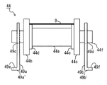
도 2a는 반송 롤러(42)의 구성예를 도시하는 평면도이다.
도 2b는 반송 롤러(42)의 동작예를 도시하는 우측면도이다.
도 2c는 베어링 부재(47)의 구성예를 도시하는 측면도이다.
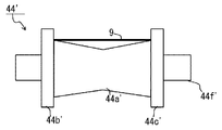
도 3a는 반송 롤러(44)의 구성예를 도시하는 평면도이다.
도 3b는 반송 롤러(44)의 변형예로서의 반송 롤러(44')의 구성예를 도시하는 평면도이다.
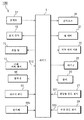
도 4는 플럭스 도포 장치(100)의 제어계의 구성예를 도시하는 블록도이다.
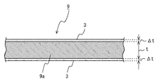
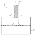
도 5a는 땜납(9)의 구성예를 도시하는 단면도이다.
도 5b는 땜납(9)의 형성예를 도시하는 공정도이다.1 is a schematic plan view showing a configuration example of a
2A is a plan view showing a configuration example of the
2B is a right side view showing an operation example of the
2C is a side view showing a structural example of the bearing
Fig. 3A is a plan view showing a configuration example of the
Fig. 3B is a plan view showing a configuration example of the conveying roller 44 'as a modification of the
4 is a block diagram showing an example of the configuration of a control system of the
5A is a cross-sectional view showing a configuration example of the
Fig. 5B is a process drawing showing an example of forming the
이하, 도면을 참조하면서, 본 발명에 관한 플럭스 도포 장치 및 플럭스 도포 장치에 의해 형성되는 플럭스 코트 프리폼 땜납의 실시 형태에 대하여 설명한다.Hereinafter, embodiments of flux coat preform solder formed by the flux applying apparatus and the flux applying apparatus according to the present invention will be described with reference to the drawings.
[플럭스 도포 장치(100)의 구성예][Example of composition of flux applying device 100]
도 1에 도시한 플럭스 도포 장치(100)는, 일례로서 소정의 폭을 갖는 긴 띠 형상으로 성형된 땜납의 표면에 균일 막 두께의 플럭스(3)를 도포하는 장치이다. 땜납의 반송 방향에 대하여, 긴 띠 형상으로 성형된 땜납을 조출하여(공급), 플럭스조(30)에 투입하는 측, 즉, 도면 중 좌측이 상류이다. 한편, 플럭스조(30)로부터 배출하여, 땜납을 권취하는 측, 즉, 우측이 하류이다. 땜납은, 상류로부터 하류로 반송된다. 본 예에서는, 플럭스(3) 도포 전의 땜납을 땜납(9a) 및 플럭스(3) 도포 후의 땜납을 땜납(9)으로서 이하 설명한다.The
플럭스 도포 장치(100)는 땜납 공급부(1), 땜납(9a)에 플럭스(3)(도면 중 배껍질 무늬)를 도포하는 플럭스 도포실(2), 플럭스(3) 도포 후의 땜납(9)을 반송하는 반송부(4), 반송된 땜납(9)을 권취하는 권취부(6), 땜납 공급부(1)의 하류이며 플럭스 도포실(2)의 상류에 위치하는 브레이크 롤러(16) 및 플럭스 도포 장치(100)의 각 동작을 제어하는 제어부(5)를 구비한다. 플럭스 도포 장치(100)에는, 플럭스(3) 도포 후의 땜납(9)의 막 두께를 측정하기 위한 막 두께계(40)를 설치해도 된다.The
땜납 공급부(1)는, 예를 들어 롤 형상으로 땜납(9a)이 감겨진 조출 릴(11), 조출된 땜납(9a)의 조출 상태를 검지하는 조출 버퍼 센서(13)를 구비한다.The
조출 릴(11)에는, 도시하지 않은 모터가 설치되어 있어, 소정의 회전 속도로 회전하도록 구동된다.The
조출 버퍼 센서(13)는, 일례로서 땜납(9a)의 반송 방향에 대하여 상하로 배치된 1쌍의 센서(도시하지 않음)로 이루어지고, 땜납(9a)을 조출 릴(11)로부터 조출할 때에, 조출 릴(11)과 브레이크 롤러(16) 사이에서 땜납(9a)의 조출 상태(휨량)를 검지한다.The
브레이크 롤러(16)보다 하류측에서, 땜납(9, 9a)의 반송 속도가 변하면, 땜납(9a)에 도포되는 플럭스(3)의 양이 변한다. 그 때문에, 반송 속도에 불균일이 있으면, 땜납(9a)에 균일한 두께로 플럭스(3)가 도포되지 않는다. 예를 들어, 땜납(9a)의 반송 속도가 빨라지면, 플럭스(3)가 땜납(9a)에 두껍게 도포된다. 또한, 땜납(9a)의 반송 속도가 느려지면, 플럭스(3)가 땜납(9a)에 얇게 도포된다.The amount of the
즉, 땜납(9a)에 균일한 플럭스(3)를 도포하기 위해서는, 브레이크 롤러(16)보다 하류에 있어서 땜납(9, 9a)을 정속으로 반송하는 것, 및, 브레이크 롤러(16)보다 상류측의 땜납 반송의 상태가, 브레이크 롤러(16)보다 하류측의 땜납 반송에 영향을 주지 않도록 하는 것이 필요하다.That is, in order to apply the
땜납(9a)의 휨량이 적어진 경우에는, 조출 버퍼 센서(13)는 상측의 센서(도시하지 않음)에 의해 검지하고, 제어부(5)를 통해 조출 릴(11)의 회전을 빠르게 하여, 휨량을 조정한다. 또한, 휨량이 많아진 경우에는, 조출 버퍼 센서(13)는 하측의 센서(도시하지 않음)에 의해 검지하고, 제어부(5)를 통해 조출 릴(11)의 회전을 느리게 하여, 휨량을 조정한다. 즉, 땜납(9a)의 휨량이 일정 범위를 초과하거나 혹은 하회하는 경우, 조출 버퍼 센서(13)가 제어부(5)에 경보 신호 S13을 보냄으로써, 조출 릴(11)의 회전 속도가 변경된다.The
이와 같이 하여, 브레이크 롤러(16)보다 하류측에서, 땜납(9, 9a)의 반송 속도에 영향을 주지 않고, 브레이크 롤러(16)보다 상류측에서의 땜납(9a)의 조출을 행할 수 있으므로, 플럭스(3)의 도포량이나 도포 두께가 균일한 땜납(9)을 제공할 수 있다.As described above, since the
플럭스 도포실(2)은 하우징을 이루고 있다. 플럭스 도포실(2)의 상류측(도면 중 좌측)의 벽의 하방에는, 땜납(9a)을 반입하기 위한 반입구(38)를 마련한다. 플럭스 도포실(2)의 하류측(도면 중 우측)의 벽의 상방은, 반출구(39)를 마련한다. 반출구(39)를 경계로 한 플럭스 도포실(2)의 내외에 걸쳐, 땜납(9)을 반송부(4)에 반출하기 위한 반송 롤러(41)를 설치한다. 플럭스 도포실(2)의 내부에는, 땜납(9)이 통과하는 순(도면 중 아래로부터 위)으로, 플럭스조(30), 가열 건조로(20), 차열 에어 커튼(24), 배기구(25), 쿨러(26), 땜납용 온도 센서(27), 실내 온도 센서(28) 및 땜납용의 인상 롤러(37)를 구비한다. 플럭스 도포실(2)의 외부에는, 조작부(14), 표시 장치(15) 등의 유저 인터페이스를 구비한다.The
플럭스조(30)에는, 유기산 등의 활성제 성분과 용제(이소프로필알코올 등) 등을 포함하는 액상의 플럭스(3)가 넣어진다. 플럭스조(30)는 땜납(9a)을 플럭스(3)에 침지하여 땜납(9a)의 표면에 플럭스(3)를 도포하는 침지 도포 수단이며, 본 예의 경우, 그 단면은, 직사각형의 하부 2코너를 좌우 대칭의 빗변으로 잘라낸 육각형을 하고 있다. 이 형상으로 한 것은, 플럭스조(30) 내에 저류하는 플럭스(3)의 양을 삭감하기 위해서이지만, 이에 한하지 않고, 직사각형이나 정사각형이어도 된다. 플럭스(3)의 온도는, 안정된 상태에서 저류되기 때문에, 일례로서 상온의 25℃ 정도로 유지된다. 플럭스(3)의 온도가 변화되면, 점도가 변화되므로, 땜납(9a)에의 플럭스 도포량이 변화되어 버려, 땜납(9a)에 도포되는 플럭스(3)가 불균일한 막 두께로 된다. 플럭스(3)를 25℃ 정도의 일정 온도로 유지하는 것은, 이것을 방지하기 위해서이다. 또한, 플럭스(3)의 휘발성 성분이 휘발되면 비중이 변화된다. 이 비중의 변화에 의해서도 땜납(9a)에의 도포량이 변화되어 버려, 땜납(9a)에 도포되는 플럭스(3)가 불균일한 막 두께로 되는 원인으로 되므로, 비중의 관리를 행하도록 해도 된다.In the
이 예에서, 플럭스조(30)의 상부에는, 상부 덮개(32)가 설치되어 있고, 상부 덮개(32)에는 개구부(33, 34)가 마련된다. 개구부(33)는 땜납(9a)의 플럭스조(30)에의 입구부를 구성하고, 개구부(34)는 땜납(9)의 플럭스조(30)에의 출구부를 구성한다.In this example, an
상부 덮개(32)의 좌측 위에는, 종동식의 반송 롤러(31)가 설치된다. 반송 롤러(31)는 땜납(9a)이 플럭스조(30)에 진입할 때에 상부 덮개(32)나 플럭스조(30) 등에 접촉하지 않도록, 땜납(9a)의 진행 방향을 변경한다.On the left side of the
플럭스조(30)의 내부에는, 땜납(9)의 반송에 종동하는 반송 롤러(36)가 설치된다. 베어링 부재(36a)가 플럭스조(30)의 상부 덮개(32)로부터 현수하는 형태로 설치되어, 반송 롤러(36)를 축 지지한다. 반송 롤러(36)는 플럭스조(30)에 침지한 땜납(9)의 반송 방향을, 하측 방향으로부터 상측 방향으로 유턴시킨다. 반송 롤러(36)에 의해 상향으로 반송 방향이 변경된 땜납(9)은 접점(36b)으로부터 반송 롤러(36)에서 이격된다.Inside the
인상 롤러(37)는 플럭스 도포실(2) 내의 천장부로부터 베어링 부재(37a)가 현수하는 형태로 설치된다. 인상 롤러(37)는 땜납(9)의 반송에 종동하는 롤러이다. 인상 롤러(37)는 플럭스조(30)에 침지한 땜납(9)을 수직으로 끌어올리기 위해, 반송 롤러(36)의 상부에 설치된다. 접점(36b)으로부터 반송 롤러(36)를 이격한 땜납(9)은, 인상 롤러(37)와의 접점(37b)으로부터 끌어올려진다. 접점(37b)은 접점(36b)의 연직 상향에 위치한다.The pulling
본 예에서는, 반송 롤러(36)와 인상 롤러(37)가, 침지 도포 수단인 플럭스조(30)에 침지하여, 플럭스(3)가 도포된 땜납(9)을 플럭스(3)의 액면에 대하여 수직으로 끌어올리는 반송 경로를 구성하는 반송 경로 형성 수단이다.The conveying
가열 건조로(20)는 플럭스(3)가 도포된 땜납(9)을 가열·건조하는 건조 수단이다. 가열 건조로(20)는 플럭스조(30)의 상방에 설치되는 세로로 긴 하우징이며, 가열 건조로(20)의 천장부와 저부의 중심에는, 땜납(9)의 통로 구멍(20a, 20b)을 갖는다. 플럭스(3)가 도포된 땜납(9)은, 통로 구멍(20b)으로부터 가열 건조로(20) 내에 진입하고, 가열 건조로(20) 내에서 가열·건조되고, 통로 구멍(20a)으로부터 배출된다.The
가열 건조로(20)의 가열 온도는, 플럭스(3)에 포함되는 용제를 휘발시키기 위해 90∼110℃로 유지된다. 가열 건조로(20)의 하우징의 벽 내에는, 도시하지 않은 단열재가 구비된다. 이 단열재에 의해, 열을 잃지 않고, 효율적으로 땜납(9)을 가열 건조할 수 있다.The heating temperature of the
가열 건조로(20)는 덕트(22)를 통해 플럭스 도포실(2)의 외부에 설치된 히터(21)와 접속하고 있다. 히터(21)는 덕트(22)를 통해 열풍을 가열 건조로(20)에 보낸다. 열풍이 땜납(9)에 직접 닿아 플럭스(3)의 막 두께를 변화시키지 않도록 하기 위해, 덕트(22)의 분출구에는 방풍벽(23)이 설치되어 있다.The
차열 에어 커튼(24)은 가열 건조로(20)로부터 배출되는 열기 및 휘발한 용제를 차단하여, 차열 에어 커튼(24)보다도 상부로 흐르는 것을 방지하는 것이다. 차열 에어 커튼(24)은 가열 건조로(20)의 상방에, 땜납(9)의 통로를 중심으로 하여 좌우에 설치된다. 차열 에어 커튼(24)은 통로 구멍(20a)으로부터 나오는 가열된 기체를 향하여(도면 중 흰색 화살표의 방향) 공기를 보낸다. 이 기압은, 일례로서 380L/min, 0.56㎫ 정도이다.The heat shielding
쿨러(26)는 가열 건조된 땜납(9)을 냉각하는 냉각 수단이며, 차열 에어 커튼(24)의 상방에 땜납(9)의 통로를 중심으로 하여 좌우에 1개씩 설치된다. 쿨러(26)에는, 히트 펌프식의 쿨러나 보텍스 쿨러 등이 사용된다. 쿨러(26)는 반송되는 땜납(9)(도면 중 검은색 화살표의 방향)에 바람을 보내어, 가열된 상태의 땜납(9)을 (예를 들어 40℃ 이하로) 냉각한다. 쿨러(26)의 풍압은, 일례로서 250L/Min, 0.2㎫ 정도이다. 이와 같이 플럭스(3)를 가열 건조하고, 냉각하는 공정을 거침으로써, 땜납(9a)에 도포된 플럭스(3)가 다른 부재에 부착되거나 고착되거나 하는 일이 없어진다. 그 때문에, 땜납(9a)에의 플럭스 도포를 안정적으로 계속할 수 있다.The cooler 26 is a cooling means for cooling the heated and dried
배기구(25)는 건조 수단인 가열 건조로(20)의 외부 또한 플럭스 도포실(2) 내의 열기를 배출하는 배기 수단이다. 배기구(25)는 차열 에어 커튼(24)보다 위이며 쿨러(26)보다도 아래에 배기용의 구멍이 플럭스 도포실(2)에 형성되어, 플럭스 도포실(2)의 외부에 연통된다. 배기구(25)는 하우징의 플럭스 도포실(2) 내이며 또한 가열 건조로(20)의 외부의 열기나 휘발한 용제 등을, 플럭스 도포실(2) 외부로 배출하기 위해 설치된다. 배기구(25)는 도시하지 않은 팬 및 팬을 회전시키는 모터를 구비한다. 모터가 회전 제어되면 팬이 회전하여, 플럭스 도포실(2) 내의 열기나 휘발한 용제 등이 분출된다. 배기구(25)에는 방화 댐퍼를 구비해도 된다.The
땜납용 온도 센서(27)는 비접촉형의 센서이며, 플럭스 도포실(2) 내의 쿨러(26)의 상방에 설치된다. 땜납용 온도 센서(27)는 냉각 후의 땜납(9)의 표면 온도를 측정한다. 예를 들어, 땜납(9)의 표면 온도가 40℃ 이상인 경우, 땜납용 온도 센서(27)는 제어부(5)에 경보 신호 S27을 보낸다.The
실내 온도 센서(28)는 플럭스 도포실(2) 내의 상부에 설치된다. 실내 온도 센서(28)는 플럭스 도포실(2) 내의 온도를 측정한다. 예를 들어, 플럭스 도포실(2) 내의 온도가 60℃ 이상인 경우, 실내 온도 센서(28)는 제어부(5)에 경보 신호 S28을 보낸다.The
반송 롤러(41)는 땜납(9)의 반송에 종동하는 종동 롤러이다. 반송 롤러(41)는 플럭스 도포실(2)의 반출구(39)로부터 플럭스 도포실(2)의 내외에 걸쳐 도시하지 않은 베어링 부재에 축 지지되어 설치된다. 본 예의 반송 롤러(41)에는, 상하 2개의 롤러 부재를 설치하는 구성으로 하고 있지만 이것에 한정되지 않는다. 상하 2개의 롤러 부재로서, 후술하는 롤러 부재(45, 46)를 이용할 수 있다.The conveying
반송부(4)에는, 플럭스 도포된 땜납(9)을 반송하는 반송 수단을 구비한다. 반송 수단으로서, 반송부(4)는 상하 2개의 롤러 부재를 갖는 반송 롤러(42, 43)와, 1개의 롤러 부재를 갖는 반송 롤러(44)를 구비한다. 본 예에서는, 반송 롤러(42, 43, 44)는 종동 롤러로 하지만, 모터 구동되어도 된다. 모터 구동되는 경우에는, 땜납(9)의 정속 반송을 행하기 위한 반송 롤러로서 사용해도 된다. 또한, 반송부(4)에 구비하는 반송 롤러의 개수 및 각 반송 롤러의 롤러 부재의 개수는, 이것에 한정되지 않는다.The
반송 롤러(42, 43)는, 상하의 롤러 부재가 땜납(9)의 양쪽 폭 단부를 끼움 지지하여, 땜납(9)의 반송 속도에 맞추어 회전하는 종동 롤러이다.The conveying
도 2a∼도 2c를 참조하여, 상하 2개의 롤러 부재를 갖는 반송 롤러(42)의 구성예 및 동작예를 설명한다. 본 예에 있어서의 반송 롤러(41, 43)도 동일한 구성으로 이루어진다. 도 2a에 도시한 반송 롤러(42)는, 상하의 롤러 부재(45, 46)로 땜납(9)의 양쪽 폭 단부를 사이에 놓고, 땜납(9)을 반송하는 것이다.A configuration example and an operation example of the conveying
롤러 부재(45)는 플랜지(45a, 45b) 및 회전축(42a)을 갖는다. 롤러 부재(46)는 그 좌우 단부에 대플랜지(46a, 46b)를 갖는다. 롤러 부재(46)의 대플랜지(46a, 46b)의 내측에는, 대플랜지(46a, 46b)보다도 작은 소플랜지(46c, 46d)를 갖는다.The
롤러 부재(45, 46) 및 회전축(42a, 42b)의 직경은 임의이다. 롤러 부재(45, 46)의 전체 폭 w1은 동일한 것이 바람직하다. 플랜지(45a)의 단부로부터 플랜지(45b)의 단부까지의 폭 w2는, 소플랜지(46c)의 단부로부터 소플랜지(46d)의 단부까지의 폭과 동일한 것이 바람직하다. 플랜지(45a, 45b)의 폭 w3은, 소플랜지(46c, 46d)의 폭과 동일한 것이 바람직하다. 이에 의해, 플랜지(45a)와 소플랜지(46c)가 맞물리고, 플랜지(45b)와 소플랜지(46d)가 맞물린다. 그 때문에, 플랜지(45a)와 소플랜지(46c)가 땜납(9)의 폭의 일단을 끼움 지지하고, 플랜지(45b)와 소플랜지(46d)가 땜납(9)의 폭의 타단을 끼움 지지하면서 땜납(9)을 반송하게 된다.The diameter of the
반송 롤러(42)의 베어링 부재(47)는 직사각형의 상하에 지지 볼록부(47', 47")를 갖는 형상이다. 지지 볼록부(47')는 구멍(47a)을 갖는다. 베어링 부재(47)는 그 측면의 상하에 2개소, 관통 구멍(47b, 47c)을 갖는다. 관통 구멍(47b, 47c)은, 롤러 부재(45, 46)의 회전축(42a, 42b)을 관통시키기 위한 것이다. 도 2c에 도시한 관통 구멍(47b)은 세로로 긴 라운딩 처리된 직사각형이다. 관통 구멍(47b)의 폭 w4는 회전축(42a)보다 한층 크다. 관통 구멍(47b)의 세로의 길이는, 롤러 부재(45)가 롤러 부재(46)에 대하여 분리 접촉 방향으로 이동할 수 있는 임의의 길이로 할 수 있다. 베어링 부재(47)의 저부에는, 다이 등에 베어링 부재(47)를 설치하기 위한 나사 구멍(47d)을 형성한다. 관통 구멍(47c)의 직경 φ는 롤러 부재(46)의 회전축(42b)보다도 한층 크다.The bearing
베어링 부재(48)는 베어링 부재(47)와 동일 형상의 부재를 좌우 반전하여 배치한 것이며, 직사각형의 상하에 지지 볼록부(48', 48")를 갖는다. 지지 볼록부(48')는 구멍(48a)을 갖는다. 베어링 부재(48)는 그 측면의 상하 2개소에 관통 구멍(48b, 48c)을 갖는다. 관통 구멍(48b, 48c)은, 롤러 부재(45, 46)의 회전축(42a, 42b)을 관통시키기 위한 것이다. 베어링 부재(48)의 저부에는, 다이 등에 베어링 부재(48)를 설치하기 위한 나사 구멍(48d)을 형성한다.The bearing
롤러 부재(45)의 회전축(42a)의 양단은, 그 반경 방향으로 나사 구멍(42c, 42d)을 갖는다. 나사(45c)는 베어링 부재(47)의 구멍(47a)을 통과하여 회전축(42a)의 나사 구멍(42c)에 체결된다. 지지 볼록부(47')와 회전축(42a) 사이의 나사(45c)가 스프링(42e) 내에 넣어진다. 나사(45d)는 베어링 부재(48)의 구멍(48a)을 통과하여 회전축(42a)의 나사 구멍(42d)에 체결된다. 지지 볼록부(48')와 회전축(42a) 사이의 나사(45d)가 스프링(42f) 내에 넣어진다. 이에 의해, 롤러 부재(45)가 나사(45c, 45d), 스프링(42e, 42f)을 아암으로 하여 현수하는 형태로 설치된다.Both ends of the
도 2b에 있어서, 땜납(9)이 롤러 부재(45, 46)의 사이를 통과할 때, 땜납(9)의 폭 방향의 일단이 롤러 부재(45)의 플랜지(45b)와 롤러 부재(46)의 소플랜지(46d) 사이에 끼움 지지된다. 땜납(9)이 좌측으로부터 우측으로(도면 중 검은색 화살표 방향) 반송되어, 롤러 부재(46)의 원주 외부를 통과하여 위로부터 아래로 반송될 때, 땜납(9)의 반송에 수반하여, 도면 중 화살표로 나타내는 바와 같이 롤러 부재(45)가 반시계 방향으로, 롤러 부재(46)가 시계 방향으로 회전한다.2B, when the
도 2a에 있어서, 땜납(9)이 롤러 부재(45, 46)의 사이를 통과할 때, 땜납(9)의 두께와 동일한 만큼 롤러 부재(45)가 들어 올려진다. 롤러 부재(45)가 들어 올려진 만큼, 스프링(42e, 42f)이 롤러 부재(45)에 하향의 탄성력을 부여한다. 이에 의해, 반송하는 땜납(9)을 탄성적으로 끼움 지지하면서, 땜납(9)을 반송할 수 있게 된다. 또한, 1개의 원기둥 형상의 롤러로 반송할 때와 비교하여, 반송 중에 롤러가 접촉하는 땜납(9)의 면적이 작아지기 때문에, 땜납(9)의 연신이나 변형을 방지하여, 품질 유지하면서 반송할 수 있다.2A, when the
도 1에 도시한 반송 롤러(44)는 땜납(9)의 반송에 종동하는 롤러이다. 도 3a에 도시한 반송 롤러(44)는 롤러 부재(46)와 동일 형상이며, 원기둥 형상의 롤러 본체(44a), 대플랜지(44b, 44c), 각 대플랜지의 내측의 소플랜지(44d, 44e), 회전축(44f)을 구비한다. 반송 롤러(44)의 회전축(44f)은 베어링 부재(49a, 49b)의 회전축 삽입용의 구멍(49c, 49d)에 삽입 관통된다. 베어링 부재(49a, 49b)는, 직사각형의 저부에 지지 볼록부(49a', 49b')를 갖는다. 지지 볼록부(49a', 49b')의 나사 구멍(49e, 49f)은, 베어링 부재(49a, 49b)를 다이 등에 설치하기 위해 형성된다.The conveying
반송 롤러(44)는 소플랜지(44d, 44e) 상에 땜납(9)의 양쪽 폭 단부를 태워 땜납(9)을 반송하기 때문에, 반송 중에 롤러가 접촉하는 땜납(9)의 면적을 작게 한다. 이에 의해, 땜납(9)을 품질을 유지한 상태에서 반송할 수 있다.The conveying
도 3b에 도시한 반송 롤러(44)의 변형예로서의 반송 롤러(44')는, 롤러 본체(44a'), 플랜지(44b', 44c'), 회전축(44f')을 구비하고, 도시하지 않은 베어링 부재에 축 지지된다. 롤러 본체(44a')는 대략 모래 시계 형상을 갖는다. 즉 롤러 본체(44a')는, 양단부가 넓고 중심으로 갈수록 점차 직경이 작아져, 중간 부분의 직경이 가장 작은 형상으로 되어 있다.The conveying roller 44 'as a modification of the conveying
반송 롤러(44')는, 반송 롤러(44') 상에 땜납(9)의 양쪽 폭 단부를 태워 땜납(9)을 반송한다. 그 때문에, 롤러 본체(44a')에 접촉하는 땜납(9)의 면적이 작아진다. 이에 의해, 땜납(9)의 품질을 유지한 상태에서 땜납(9)을 반송할 수 있다. 또한, 도 3a에 도시한 소플랜지(44d, 44e) 상에 땜납(9)을 태우는 구성의 반송 롤러(44)와는 달리, 롤러 본체(44a')의 형상을 고안하여 땜납(9)에 접촉하는 면적을 적게 하였다. 이 때문에, 소플랜지(44d, 44e)의 폭과 관계없이, 롤러 본체(44a')의 전체 길이보다도 좁은 모든 폭의 땜납(9)을 반송할 수 있게 되었다. 반송 롤러(44, 44')의 구성은, 반송 롤러(31, 36), 속도 검지 롤러(64), 인상 롤러(37)에도 이용할 수 있다.The conveying roller 44 'conveys the
도 1에 도시한 권취부(6)는 땜납(9)의 권취기(66), 층간지 공급 롤러(65), 권취기(66)의 상류에서 권취 속도를 계측하는 레이저 센서(63), 레이저 센서(63)의 하방에 설치되는 속도 검지 롤러(64)를 구비한다.The winding
권취기(66)는 침지 도포 수단인 플럭스조(30)보다도 하류측에 설치되며 제어부(5)에 회전 속도가 제어된, 땜납(9)을 권취하는 권취 수단이다. 본 예에 있어서, 권취기(66)는, 브레이크 롤러(16)에 의해 부하가 부여된 상태에서 플럭스조(30)에 침지되고 수직으로 끌어올려지는 땜납(9)을, 제어부(5)의 제어에 의해 소정의 속도로 반송하는 정속 반송 수단을 구성한다. 또한, 정속 반송 수단은, 권취기(66)와는 별도로 구비되어 있어도 된다.The
권취기(66)는 땜납(9)을 반송 속도 v로 반송하도록 회전하여 권취한다. 권취기(66)에 의해 권취되는 땜납(9)은, 플럭스조(30)의 상류측에서 브레이크 롤러(16)에 의해 소정의 장력이 부여된 상태에서 플럭스조(30)로부터 끌어올려진다. 이에 의해, 안정된 땜납(9)의 반송 속도 v가 실현된다. 권취기(66)는 도시하지 않은 모터를 설치하고 있고, 제어부(5)가 모터를 회전 제어함으로써 소정의 속도로 회전한다.The winder (66) rotates and winds the solder (9) so as to transport the solder (9) at the conveying speed (v). The
층간지 공급 롤러(65)는 땜납(9)의 반송에 종동하여 회전한다. 권취기(66)가 땜납(9)을 권취할 때, 층간지(67)는 권취한 땜납(9)끼리가 접촉하지 않도록, 땜납(9) 사이에 끼워지는 위치에 공급된다. 층간지(67)에는, 땜납(9)과 동일 폭의 긴 형상의 종이가 사용된다.The
레이저 센서(63)는 땜납(9)의 반송 속도 v를 계측하는 반송 속도 계측 수단이며, 계측 결과로서 펄스 신호를 제어 수단에 송신하는 비접촉형의 센서이다. 속도 검지 롤러(64)는 레이저 센서(63)의 하부에 설치되며, 땜납(9)의 반송에 종동하여 회전한다. 속도 검지 롤러(64)는 그 원주 상의 1점에 레이저 센서(63)로부터의 레이저광을 반사하는 반사체(64a)를 설치한다.The
속도 검지 롤러(64)의 회전에 수반하여 반사체(64a)가 레이저 센서(63)로부터 조사된 레이저광을 반사한다. 레이저 센서(63)는 반사광이 레이저 센서(63)에 입사한 것을 검지하고, 제어부(5)에 펄스 신호로서 전달한다. 제어부(5)는 수신한 펄스 신호의 횟수로부터, 1분마다의 속도 검지 롤러(64)의 회전수를 계산한다. 제어부(5)는 이 1분마다의 회전수로부터 땜납(9)의 반송 속도 v'를 계산한다. 제어부(5)는 이 정보에 기초하여 권취기(66)의 회전 속도를 제어하여, 땜납(9)을 균일한 반송 속도 v로 반송시킨다. 땜납(9)이 일정한 반송 속도 v로 수직으로 끌어올려짐으로써, 땜납(9a)과 플럭스(3) 사이에 계면 장력이 작용하기 때문에, 땜납(9a)의 표리에 반송 속도 v에 따른 균일 막 두께의 플럭스(3)가 잔류한다.The
브레이크 롤러(16)는 플럭스조(30)보다도 상류측에 설치되며, 권취 수단인 권취기(66)와 협동하여 땜납에 반송 방향을 따른 소정의 부하를 부여하는 부하 수단이다. 통상의 롤러에 비해 상하 롤러의 닙 부위의 압착력이 약간 높게 설정된다. 브레이크 롤러(16)는 조출 릴(11)과 플럭스조(30) 사이에 설치된다. 이것은, 브레이크 롤러(16)가 권취기(66)와 협동하여 땜납(9, 9a)에 장력을 부여함으로써, 플럭스(3)가 도포된 땜납(9)을 일정한 반송 속도 v로 수직으로 끌어올리기기 위해서이다. 반송 속도 v로 수직으로 끌어올려진 땜납(9)에는, 플럭스(3)가 균일한 막 두께로 피복된다.The
브레이크 롤러(16)는 플럭스 도포실(2) 내의 온도 변화나 습도 변화의 영향을 받지 않도록, 플럭스 도포실(2)의 외부에 설치되는 것이 바람직하지만, 플럭스 도포실(2) 내에 설치되어 있어도 된다. 브레이크 롤러(16)에는, 금속 롤러나, 내열성의 고무 롤러, 탄소 롤러, 수지 롤러 등의 롤러 부재를 사용할 수 있다.The
[땜납(9)의 반송 속도 제어에 대하여][Regarding the conveying speed control of the solder 9]
계속해서, 도 4를 참조하여, 플럭스 도포 장치(100)의 제어 수단의 구성에 대하여 설명한다. 제어부(5)는 땜납(9)의 반송 속도를 제어하기 위해, 조작부(14), 표시 장치(15), 조출 릴(11), 조출 버퍼 센서(13), 권취기(66), 레이저 센서(63), 속도 검지 롤러(64) 등에 접속한다.Next, the configuration of the control means of the
제어부(5)는 시스템 전체를 제어하기 위해, 예를 들어 ROM(Read Only Memory), RAM(Random Access Memory), CPU(Central Processing Unit) 및 메모리부를 갖는다. ROM에는, 예를 들어 플럭스 도포 장치(100)의 전체를 제어하기 위한 시스템 프로그램이 저장된다.The
조작부(14)는 도시하지 않은 텐키나 터치 패널 등의 입력부를 갖는다. 조작부(14)는 플럭스 도포 장치(100)에 있어서의 플럭스(3)의 막 두께 제어 조건 등을 설정하기 위한 것이다. 막 두께 제어 조건에는, 땜납(9a) 및 플럭스(3)의 각각의 조성, 크기, 온도 등이 포함된다.The
제어부(5)는 땜납(9)을 수직으로 끌어올리고, 또한 플럭스(3)의 조성에 대응한 반송 속도 v를 제어한다. 이에 의해, 땜납(9)으로부터 일정하게 플럭스(3)의 잉여분을 제거하여, 땜납(9)에의 플럭스(3)의 막 두께를 제어하도록 이루어진다. 그 제어 스텝에 대하여 이하에서 설명한다.The
작업자는, 조작부(14)에 의해 막 두께 제어 조건 등을 입력한다. 제어부(5)는 입력된 막 두께 제어 조건에 기초하여, 땜납(9)의 반송 속도 v의 반송 속도 제어 데이터를 생성한다.The operator inputs the film thickness control condition or the like by the
제어부(5)는 반송 속도 제어 데이터에 기초하여 조출 릴(11), 조출 버퍼 센서(13), 권취기(66), 레이저 센서(63), 속도 검지 롤러(64) 등의 입출력을 제어한다. 이하, 반송 속도 제어 데이터에 기초하는 반송 속도 v의 제어 스텝이다.The
제어부(5)는 땜납(9a)이 소정의 속도로 조출되도록, 조출 릴(11)을 회전시킨다. 조출된 땜납(9a)의 조출 상태(휨량)가 소정의 범위를 초과하였거나 혹은 하회한 경우, 조출 버퍼 센서(13)가 경보 신호 S13을 제어부(5)에 보낸다. 제어부(5)는 경보 신호 S13에 기초하여 조출 릴(11)의 회전 속도를 조정한다.The
제어부(5)는 권취기(66) 내에 장비된 도시하지 않은 구동 모터를 회전시킨다. 이에 의해, 권취기(66)와 브레이크 롤러(16)가 협동하여, 땜납(9)에 소정의 장력을 부여하면서 회전한다. 땜납(9)에 소정의 장력이 가해짐으로써, 플럭스조(30)에 침지된 땜납(9)은 반송 속도 v(v=700[㎜/min])를 유지하면서 플럭스조(30)로부터 끌어올려진다. 땜납(9)의 반송 속도 v는, 브레이크 롤러(16)로부터 플럭스조(30)를 경유하여 권취기(66)에 권취될 때까지 일정하게 이루어진다.The
제어부(5)는 레이저 센서(63) 및 속도 검지 롤러(64)로부터 얻어진 펄스 신호에 기초하여, 속도 검지 롤러(64)의 1분마다의 회전수를 계산하고, 이 회전수에 기초하여, 땜납(9)의 실제의 반송 속도 v'를 계산한다. 계산한 땜납(9)의 반송 속도 v'를 반송 속도 v=700[㎜/min]으로 유지하도록, 제어부(5)는 권취기(66)의 회전 속도를 조정한다. 이에 의해, 일례로서 편면 10㎛의 얇은 균일한 막 두께의 플럭스(3)를 땜납(9a)에 도포할 수 있다.The
또한, 제어부(5)는 온도 제어도 행한다. 제어부(5)는 플럭스조(30)에 장비된 도시하지 않은 온도 조정 장치를 구동하여, 플럭스조 내의 플럭스(3)의 온도를 일정(예를 들어 25℃)하게 유지한다.The
제어부(5)는 가열 건조로(20)에 접속된 히터(21)를 구동한다. 히터(21)는 가열 건조로(20) 내의 온도를 90∼110℃로 되도록 가열·건조한다.The
제어부(5)는 차열 에어 커튼(24)을 구동하여, 통로 구멍(20a)으로부터 나오는 가열된 기체의 방향으로 공기를 분사하여, 가열 건조로(20)로부터의 열풍 및 휘발한 용제가 플럭스 도포실(2)에 퍼지지 않도록 한다.The
제어부(5)는 배기구(25)에 설치되는 도시하지 않은 팬을 구동하여, 배기구(25)가 가열 건조로(20)로부터 플럭스 도포실(2) 내로 나온 열기를 플럭스 도포실(2) 외부로 배출시킨다.The
제어부(5)는 배기구(25)의 팬(도시하지 않음)을 구동하고, 배기구(25)의 팬과 접속하는 모터를 회전시킨다. 모터가 회전 제어되면 팬이 회전하여, 플럭스 도포실(2) 내의 열기가, 배기구(25)에 흡입된다.The
제어부(5)는 쿨러(26)를 구동하여, 가열 건조 후의 땜납(9)에 냉풍을 분사하여 냉각시킨다. 이때, 쿨러(26)에 의해 땜납(9)을 40℃ 이하로 냉각하는 것이 바람직하다.The
제어부(5)는 땜납용 온도 센서(27)에 접속된다. 땜납용 온도 센서(27)는 땜납(9)의 온도를 항상 측정한다. 땜납(9)이 일정 온도(예를 들어 40℃)를 초과한 경우, 땜납용 온도 센서(27)는 제어부(5)에 경보 신호 S27을 보낸다. 제어부(5)가 경보 신호 S27을 수취하면, 제어부(5)는 땜납(9)의 온도가 일정 온도로 내려갈 때까지 조출 릴(11), 권취기(66) 등의 회전을 정지시킨다.The
제어부(5)는 플럭스 도포실(2)의 실내 온도 센서(28)에 접속된다. 실내 온도 센서(28)는 플럭스 도포실(2) 내의 온도를 항상 측정한다. 플럭스 도포실(2) 내가 일정 온도(예를 들어 60℃)를 초과한 경우, 실내 온도 센서(28)는 제어부(5)에 경보 신호 S28을 보낸다. 제어부(5)가 경보 신호 S28을 수취하면, 제어부(5)는 플럭스 도포실(2)의 온도가 일정 온도로 내려갈 때까지 히터(21) 및 땜납(9)의 반송을 정지시킨다. 또한, 플럭스 도포실(2) 내의 온도가 일정 온도로 내려갈 때까지, 플럭스 도포실(2)의 도어(도시하지 않음)를 개방하지 않도록 한다.The
상술한 제어 스텝의 순서는 이것에 한정되지 않고, 제어부(5)는 복수의 제어 스텝을 동시에 실행해도 된다. 또한, 제어부(5) 내부 또는 외부에 기억 장치를 설치하고, 막 두께 제어 조건이나 제어 데이터 등을 기억해도 된다.The order of the above-described control steps is not limited to this, and the
도 1에 도시한 비접촉형의 막 두께계(40)를 이용하여, 실시간으로 땜납(9)에의 플럭스(3)의 도포량(막 두께량)을 검지하고, 플럭스(3)의 도포량 검지에 기초하는 피드백 제어에 의해 막 두께 제어를 실행해도 된다. 피드백 제어에 의하면, 땜납(9)에의 플럭스(3)의 막 두께가 많은 경우에는, 땜납(9)의 반송 속도 v를 느리게 설정하여 땜납(9)에 도포되는 플럭스(3)를 저감시킨다. 반대로, 땜납(9)에의 플럭스(3)의 막 두께가 적은 경우에는, 땜납(9)의 반송 속도 v를 빠르게 설정하여 땜납(9)에 도포되는 플럭스(3)를 많게 한다.The coating amount (amount of film thickness) of the
[땜납(9)의 구성예][Configuration Example of Solder 9]
계속해서, 도 5a 및 도 5b를 참조하여, 플럭스 도포된 땜납(9)의 구성예에 대하여 설명한다. 도 5a에 도시한 땜납(9)은 소정의 폭 t(t=약 15㎜∼40㎜), 도시하지 않은 소정의 두께(약 0.25㎜)의 플럭스 도포 전의 땜납(9a)과, 그 땜납(9a)의 표리를 피복하는 막 두께 Δt의 플럭스(3)를 구비하고 있다.Next, with reference to Figs. 5A and 5B, an example of the configuration of the flux-applied
도 5b에 도시한 땜납(9)은 플럭스 도포 장치(100)에 있어서, 플럭스(3)의 막 두께가 제어되어 이루어지는 것이다. 플럭스(3)는 소정의 온도(예를 들어 25℃)에서 플럭스조(30)에 넣어진다. 땜납(9a)은 소정의 속도로 반송되어, 플럭스조(30) 내에 침지된다. 플럭스조(30) 내에 침지된 땜납(9a)은 플럭스조(30)로부터 도면 중 이점쇄선으로 나타내는 플럭스(3)의 액면에 대하여 수직(도면 중 검은색 화살표 방향)으로 반송 속도 v로 끌어올려진다. 일정한 반송 속도 v로 수직으로 끌어올려짐으로써, 땜납(9a)과 플럭스(3) 사이에 계면 장력이 작용하기 때문에, 땜납(9a)의 표리에 반송 속도 v에 따른 균일 막 두께의 플럭스(3)가 잔류한다. 수직으로 끌어올려진 땜납(9)은 가열 건조 공정, 냉각 공정을 거친다. 또한 땜납(9)의 온도 및 플럭스(3)의 막 두께가 측정되고 반송되어, 권취됨으로써 완성된다. 플럭스 도포 장치(100)에서는, 땜납(9, 9a)의 반송 속도 v를 제어할 수 있기 때문에, 균일한 막 두께의 플럭스(3)로 피복된 땜납(9)을 제조할 수 있다.The
이와 같이 실시 형태로서의 플럭스 도포 장치(100)에 의하면, 플럭스조(30)로부터 끌어올려진 땜납(9a)의 표면에, 플럭스(3)를 균일한 막 두께로 도포하는 것이며, 플럭스조(30), 브레이크 롤러(16), 인상 롤러(37), 가열 건조로(20), 차열 에어 커튼(24), 쿨러(26), 반송 롤러(31, 36, 37, 41, 42∼44), 레이저 센서(63), 속도 검지 롤러(64), 권취기(66)를 구비하는 것이다.As described above, according to the
이 구성에 의해, 땜납(9, 9a)을 균일한 반송 속도 v로 반송할 수 있으므로, 땜납(9a)을 피복하는 플럭스(3)의 막 두께를 균일하게 또한 10㎛ 두께 이하로 제어할 수 있게 되었다. 이에 의해, 종래 방식에 비해 막 두께가 매우 얇은 플럭스 도포를 실현할 수 있게 되었다. 또한, 잉여의 플럭스(3)를 깎아내기 위한 특별한 부재가 불필요하게 되기 때문에, 생산 비용의 저감화, 메인터넌스의 용이화를 도모할 수 있었다.This configuration makes it possible to uniformly control the film thickness of the
또한, 실시 형태로서의 땜납(9)은 플럭스(3)가 넣어진 플럭스조(30)로부터 수직으로 끌어올려지고, 또한 균일한 반송 속도 v로 반송된다.Further, the
이에 의해, 땜납(9)에 피복되는 플럭스(3)의 막 두께가 일정하게 이루어진다. 종래 방식에 비해, 땜납(9)에, 코트면의 안정성 및 평탄성이 우수한 막 두께가 얇은 플럭스(3)를 도포할 수 있다.Thus, the film thickness of the
본 예의 플럭스 도포 장치(100)는 땜납(9)을 1조 제조하는 경우에 대하여 설명하였지만, 2조 이상의 땜납(9)을 동시에 제조하는 구성으로 이루어져도 된다. 그 경우, 한 번에 많은 땜납(9)을 제조할 수 있게 되므로, 가동 비용을 저감시킬 수 있게 된다.The
또한, 땜납(9)을 브레이크 롤러(16)에 의해 부하가 부여된 상태에서 제어부(5)의 제어에 의해 소정의 속도로 반송하기 위해, 인상 롤러(37), 반송 롤러(31, 36, 41∼44)는 종동 롤러가 아니라, 제어부(5)에 접속하는 도시하지 않은 모터를 설치하고, 원하는 반송 속도 v에 따라서 일정한 속도로 회전 제어되는 정속 반송 수단이어도 된다. 플럭스조(30)는 저류하는 플럭스(3)의 액량을 제어하는 플럭스 컨트롤러나 플럭스(3)를 저류하는 서브 탱크에 접속되어도 되고, 플럭스조(30)에 저류되는 플럭스(3)의 성분 및 양이 일정하게 이루어져도 된다.In order to carry the
본 발명은 땜납에 플럭스를 균일한 막 두께로 도포하는 플럭스 도포 장치 및 당해 플럭스 도포 장치에 의해 형성되는 땜납에 적용하기에 매우 적합하다.INDUSTRIAL APPLICABILITY The present invention is well suited for application to a flux applying apparatus for applying a flux to a solder with a uniform film thickness and to a solder formed by the flux applying apparatus.
1 : 땜납 공급부
2 : 플럭스 도포실
4 : 반송부
5 : 제어부
6 : 권취부
11 : 조출 릴
13 : 조출 버퍼 센서
14 : 조작부
15 : 표시 장치
16 : 브레이크 롤러
20 : 가열 건조로
21 : 히터
24 : 차열 에어 커튼
25 : 배기구
26 : 쿨러
27 : 땜납용 온도 센서
28 : 실내 온도 센서
30 : 플럭스조
63 : 레이저 센서
64 : 속도 검지 롤러
66 : 권취기
100 : 플럭스 도포 장치1: solder supply portion
2: Flux application room
4:
5:
6:
11: Feeding reel
13: Feeding buffer sensor
14:
15: Display device
16: Brake roller
20: Heat drying furnace
21: Heater
24: Heating air curtain
25: Exhaust
26: Cooler
27: Temperature sensor for solder
28: Room temperature sensor
30: flux tank
63: Laser sensor
64: Speed detecting roller
66: Winder
100: Flux application device
Claims (5)
땜납을 플럭스에 침지하여 땜납 표면에 플럭스를 도포하는 침지 도포 수단과,
땜납을 투입하는 측을 상류측, 땜납을 배출하는 측을 하류측으로 하였을 때, 상기 침지 도포 수단보다 상류측에 설치되며, 땜납에 소정의 부하를 부여하는 부하 수단과,
상기 침지 도포 수단에 의해 플럭스가 도포되고 플럭스의 액면에 대하여 수직으로 끌어올려지는 땜납을, 상기 부하 수단에 의해 부하가 가해진 상태에서, 소정의 속도로 반송하는 정속 반송 수단과,
상기 플럭스가 도포된 상기 땜납을 건조시키는 건조 수단과,
건조된 상기 땜납을 냉각하는 냉각 수단과,
상기 땜납의 반송 속도를 계측하는 반송 속도 계측 수단과,
상기 땜납의 반송 속도를 제어하는 제어 수단을 구비하는, 플럭스 도포 장치.1. A flux applying device for applying flux to a surface of a solder,
Immersion application means for immersing the solder in the flux to apply the flux to the surface of the solder,
A load means which is provided on the upstream side of the immersion applying means and applies a predetermined load to the solder when the side to which the solder is charged is defined as the upstream side and the side to which the solder is discharged is defined as the downstream side,
Constant speed conveying means for conveying the solder to which the flux is applied by the immersion applying means and pulled up vertically to the liquid level of the flux at a predetermined speed in a state in which the load is applied by the load means,
Drying means for drying the solder to which the flux is applied,
A cooling means for cooling the dried solder,
A conveying speed measuring means for measuring a conveying speed of the solder;
And control means for controlling the conveying speed of the solder.
상기 정속 반송 수단은, 반송 수단을 구비하고,
이 반송 수단은,
1 이상의 반송 롤러를 갖고,
상기 반송 롤러는, 상기 땜납을 사이에 두는 2개의 롤러 부재를 갖고,
상기 롤러 부재가, 상기 땜납의 양쪽 폭 단부를 끼움 지지하는, 플럭스 도포 장치.The method according to claim 1,
The constant speed conveying means includes conveying means,
In this conveying means,
And at least one conveying roller,
The conveying roller has two roller members sandwiching the solder,
Wherein the roller member supports both widthwise ends of the solder.
적어도 상기 침지 도포 수단, 상기 건조 수단, 상기 냉각 수단은,
플럭스 도포실 내에 수납되고,
상기 플럭스 도포실은,
상기 건조 수단 외 또한 상기 플럭스 도포실 내의 열기를 배출하는 배기 수단을 더 구비하는, 플럭스 도포 장치.3. The method according to claim 1 or 2,
At least the immersion applying means, the drying means, and the cooling means,
Is stored in the flux application chamber,
The flux coating chamber
Further comprising an exhaust means for exhausting the heat in the flux application chamber as well as the drying means.
상기 정속 반송 수단은, 권취 수단을 구비하고, 이 권취 수단에 의해 상기 땜납을 권취할 때에, 층간지를 공급하는 층간지 공급 수단을 더 구비하는, 플럭스 도포 장치.4. The method according to any one of claims 1 to 3,
Wherein the constant speed conveying means further comprises a layer separator feeding means for feeding layer separators when the solder is wound by the winding means.
Applications Claiming Priority (1)
| Application Number | Priority Date | Filing Date | Title |
|---|---|---|---|
| PCT/JP2015/059899 WO2016157357A1 (en) | 2015-03-30 | 2015-03-30 | Flux coating device and solder |
Publications (2)
| Publication Number | Publication Date |
|---|---|
| KR20170125997A true KR20170125997A (en) | 2017-11-15 |
| KR101882156B1 KR101882156B1 (en) | 2018-07-25 |
Family
ID=54776722
Family Applications (1)
| Application Number | Title | Priority Date | Filing Date |
|---|---|---|---|
| KR1020177030619A KR101882156B1 (en) | 2015-03-30 | 2015-03-30 | Flux application device |
Country Status (9)
| Country | Link |
|---|---|
| US (1) | US10391589B2 (en) |
| EP (1) | EP3281739B1 (en) |
| JP (1) | JP5825458B1 (en) |
| KR (1) | KR101882156B1 (en) |
| CN (1) | CN109121402B (en) |
| ES (1) | ES2930723T3 (en) |
| PT (1) | PT3281739T (en) |
| TW (1) | TWI572417B (en) |
| WO (1) | WO2016157357A1 (en) |
Families Citing this family (6)
| Publication number | Priority date | Publication date | Assignee | Title |
|---|---|---|---|---|
| WO2017124424A1 (en) * | 2016-01-22 | 2017-07-27 | 华封科技有限公司 | Element packaging apparatus and method thereof |
| KR101891594B1 (en) * | 2016-11-11 | 2018-08-29 | 한국생산기술연구원 | Metal layer integrated solder, pcb integrated solder and solder bonding method including the same |
| DE102018100683A1 (en) * | 2018-01-12 | 2019-07-18 | EMIL OTTO Flux- und Oberflächentechnik GmbH | Process for producing a solder |
| US10939600B2 (en) * | 2018-11-28 | 2021-03-02 | International Business Machines Corporation | Flux residue detection |
| CN113385364B (en) * | 2021-06-10 | 2023-12-29 | 卢军飞 | Pretensioned geotextile raw material gumming device |
| CN114473345A (en) * | 2022-03-15 | 2022-05-13 | 中国电子科技集团公司第三十八研究所 | Visual elastic welding frock of high rigidity |
Citations (5)
| Publication number | Priority date | Publication date | Assignee | Title |
|---|---|---|---|---|
| JPS5475452A (en) | 1977-11-29 | 1979-06-16 | Senju Metal Industry Co | Flux coated solder wire and apparatus for coating flux on wire |
| JPH0649614A (en) * | 1992-08-03 | 1994-02-22 | Kobe Steel Ltd | Production of hot dip tin coated copper alloy material having excellent corrosion resistance and solderability |
| JP2001001136A (en) * | 1999-06-17 | 2001-01-09 | Furukawa Electric Co Ltd:The | Aluminum alloy brazing filler metal with flux applied thereto, and its manufacture |
| KR20040038494A (en) * | 2002-11-01 | 2004-05-08 | 태창엔지니어링 주식회사 | Electrodeposition resist coating apparatus |
| KR20150028986A (en) * | 2012-06-11 | 2015-03-17 | 센주긴조쿠고교 가부시키가이샤 | Device for coating thin molten solder film, thin solder film-covered component and manufacturing method therefor |
Family Cites Families (32)
| Publication number | Priority date | Publication date | Assignee | Title |
|---|---|---|---|---|
| US2055393A (en) * | 1932-05-21 | 1936-09-22 | Standard Cap & Seal Corp | Wire with soldering flux coating and method of making the same |
| US3724418A (en) * | 1971-08-20 | 1973-04-03 | Lain J Mc | Solder coating apparatus |
| SE368348B (en) * | 1973-01-29 | 1974-07-01 | Graenges Essem Ab | |
| US4619841A (en) * | 1982-09-13 | 1986-10-28 | Schwerin Thomas E | Solder leveler |
| US4499120A (en) * | 1982-09-29 | 1985-02-12 | General Dynamics, Pomona Division | Method for solder tinning of component leads |
| DE3420514C2 (en) * | 1984-06-01 | 1986-04-17 | Feindrahtwerk Adolf Edelhoff GmbH & Co, 5860 Iserlohn | Process for the production of tinned wires |
| US4790686A (en) * | 1986-04-10 | 1988-12-13 | Armco Inc. | Protected metal article |
| US4762808A (en) | 1987-06-22 | 1988-08-09 | Dow Corning Corporation | Method of forming semiconducting amorphous silicon films from the thermal decomposition of fluorohydridodisilanes |
| DE4105298C2 (en) | 1990-02-21 | 1996-04-11 | Bando Chemical Ind | Diving system for attaching adhesives or adhesives to ropes |
| JPH03254392A (en) * | 1990-02-28 | 1991-11-13 | Taiyo Yuden Co Ltd | Sheet-like solder and its production |
| US5139822A (en) * | 1990-08-20 | 1992-08-18 | Amp Incorporated | Method for coating solder on selective areas of a metal strip |
| JPH04111994A (en) * | 1990-08-31 | 1992-04-13 | Showa Alum Corp | Wire-or plate-shaped brazing material coated with flux and production thereof and brazing method using this brazing material |
| US5184767A (en) * | 1991-12-31 | 1993-02-09 | Compaq Computer Corporation | Non-wicking solder preform |
| JPH07270436A (en) * | 1994-03-31 | 1995-10-20 | Nkk Corp | Length measuring apparatus for moving object |
| JP3578291B2 (en) * | 1995-09-08 | 2004-10-20 | 日本軽金属株式会社 | Method and apparatus for applying brazing composition |
| JP3254392B2 (en) | 1996-06-12 | 2002-02-04 | 株式会社リコー | Evaluation chart and image recording device |
| JPH111994A (en) | 1997-06-10 | 1999-01-06 | Shinbashikiichirou Shoten:Kk | Stranded-wire reinforcing material with opening |
| TW415867B (en) * | 1998-07-29 | 2000-12-21 | Calsonic Corp | Method for applying flux for use in brazing aluminum material, flux coating apparatus, and method for manufacturing a heat exchanger |
| CN1398212A (en) | 1999-11-23 | 2003-02-19 | 挪威海德罗公开有限公司 | Aluminium product with excellent brazing characteristics |
| US6428851B1 (en) * | 2000-03-01 | 2002-08-06 | Bethlehem Steel Corporation | Method for continuous thermal deposition of a coating on a substrate |
| JP4112330B2 (en) | 2002-10-02 | 2008-07-02 | 富士通株式会社 | Manufacturing method of semiconductor device |
| WO2007140236A1 (en) * | 2006-05-25 | 2007-12-06 | Bellman-Melcor Development, Llc | Filler metal with flux for brazing and soldering and method of making and using same |
| US8291895B2 (en) * | 2007-09-05 | 2012-10-23 | University Of South Carolina | Methods, wires, and apparatus for slicing hard materials |
| JP5409059B2 (en) | 2009-03-16 | 2014-02-05 | Juki株式会社 | Flux supply device |
| TWI446974B (en) | 2009-06-30 | 2014-08-01 | Toray Eng Co Ltd | And a conveyor device for coating the substrate on both sides |
| CN101869885B (en) * | 2010-02-04 | 2013-10-23 | 深圳市堃琦鑫华科技有限公司 | Ultrasonic soldering flux coating process and device |
| JP5367752B2 (en) | 2010-06-11 | 2013-12-11 | 古河電気工業株式会社 | Solder plated wire manufacturing method and manufacturing apparatus |
| JP5703901B2 (en) | 2011-03-31 | 2015-04-22 | 株式会社Ihi | Roll press apparatus and film thickness measuring method |
| CN103056479B (en) * | 2013-01-16 | 2014-12-31 | 中电电气(南京)光伏有限公司 | Flux spraying method and device for solar photovoltaic modules |
| JP2015013248A (en) * | 2013-07-04 | 2015-01-22 | 株式会社豊田自動織機 | Coating device and electrode manufacturing method |
| JP6426741B2 (en) * | 2013-08-29 | 2018-11-21 | アルファ・アセンブリー・ソリューションズ・インコーポレイテッドAlpha Assembly Solutions Inc. | Bonding to aluminum |
| JP5884932B1 (en) * | 2015-05-27 | 2016-03-15 | 千住金属工業株式会社 | Liquid applicator |
-
2015
- 2015-03-30 JP JP2015531772A patent/JP5825458B1/en active Active
- 2015-03-30 EP EP15887510.4A patent/EP3281739B1/en active Active
- 2015-03-30 US US15/563,017 patent/US10391589B2/en active Active
- 2015-03-30 PT PT158875104T patent/PT3281739T/en unknown
- 2015-03-30 WO PCT/JP2015/059899 patent/WO2016157357A1/en active Application Filing
- 2015-03-30 CN CN201580078611.0A patent/CN109121402B/en active Active
- 2015-03-30 KR KR1020177030619A patent/KR101882156B1/en active IP Right Grant
- 2015-03-30 ES ES15887510T patent/ES2930723T3/en active Active
-
2016
- 2016-03-29 TW TW105109807A patent/TWI572417B/en active
Patent Citations (5)
| Publication number | Priority date | Publication date | Assignee | Title |
|---|---|---|---|---|
| JPS5475452A (en) | 1977-11-29 | 1979-06-16 | Senju Metal Industry Co | Flux coated solder wire and apparatus for coating flux on wire |
| JPH0649614A (en) * | 1992-08-03 | 1994-02-22 | Kobe Steel Ltd | Production of hot dip tin coated copper alloy material having excellent corrosion resistance and solderability |
| JP2001001136A (en) * | 1999-06-17 | 2001-01-09 | Furukawa Electric Co Ltd:The | Aluminum alloy brazing filler metal with flux applied thereto, and its manufacture |
| KR20040038494A (en) * | 2002-11-01 | 2004-05-08 | 태창엔지니어링 주식회사 | Electrodeposition resist coating apparatus |
| KR20150028986A (en) * | 2012-06-11 | 2015-03-17 | 센주긴조쿠고교 가부시키가이샤 | Device for coating thin molten solder film, thin solder film-covered component and manufacturing method therefor |
Also Published As
| Publication number | Publication date |
|---|---|
| KR101882156B1 (en) | 2018-07-25 |
| PT3281739T (en) | 2022-11-28 |
| EP3281739A4 (en) | 2019-01-23 |
| JPWO2016157357A1 (en) | 2017-04-27 |
| EP3281739A1 (en) | 2018-02-14 |
| ES2930723T3 (en) | 2022-12-21 |
| US20180185967A1 (en) | 2018-07-05 |
| WO2016157357A1 (en) | 2016-10-06 |
| EP3281739B1 (en) | 2022-09-14 |
| CN109121402B (en) | 2019-12-03 |
| CN109121402A (en) | 2019-01-01 |
| JP5825458B1 (en) | 2015-12-02 |
| TW201637722A (en) | 2016-11-01 |
| TWI572417B (en) | 2017-03-01 |
| US10391589B2 (en) | 2019-08-27 |
Similar Documents
| Publication | Publication Date | Title |
|---|---|---|
| KR101647272B1 (en) | Liquid coating apparatus | |
| KR20170125997A (en) | Flux application device | |
| CN106517750B (en) | Device and method for stabilizing a sheet made of hard brittle material | |
| JP2005503487A (en) | Method and apparatus for coating the surface of a strand metal material | |
| JP2000328219A (en) | Coating plant | |
| CA2145103C (en) | Method and apparatus for processing a web of material | |
| JP5086721B2 (en) | Web heating and cooling apparatus and web heating and cooling method | |
| KR102530405B1 (en) | Apparatus and method for manufacturing float glass | |
| JP7377499B2 (en) | Sheet material manufacturing method, coating film forming method, sheet material manufacturing device, and coater | |
| KR20010090316A (en) | Mathod and apparatus for manufacturing mica tape | |
| JP7468205B2 (en) | Optical fiber manufacturing equipment | |
| JP2023044788A (en) | Manufacturing method of film | |
| JP2023143795A (en) | Thickness measuring method and thickness measuring device | |
| US20060138201A1 (en) | Method of manufacturing an electronic component and apparatus for carrying out the method | |
| CN118043618A (en) | Device and method for avoiding malfunctions of ovens for manufacturing containers, in particular cans | |
| JP2006181550A (en) | Coating device of plate edge, coating device of plate, and coating method of plate edge | |
| JP2002126606A (en) | Adhesive coating applicator | |
| JP2004356653A (en) | Resin sealing method and semiconductor chip | |
| JP2004356652A (en) | Resin sealing method and semiconductor chip | |
| JPH09230538A (en) | Method and device for manufacturing substrate of photographic film | |
| JP2004336088A (en) | Resin sealing equipment and semiconductor chip | |
| JP2003071362A (en) | Coating material drying apparatus | |
| JPH0741921A (en) | Method and device for coating strip by hot dipping | |
| JPH0785784A (en) | Photosensitive solution applying device |
Legal Events
| Date | Code | Title | Description |
|---|---|---|---|
| A201 | Request for examination | ||
| A302 | Request for accelerated examination | ||
| E902 | Notification of reason for refusal | ||
| E902 | Notification of reason for refusal | ||
| E701 | Decision to grant or registration of patent right | ||
| GRNT | Written decision to grant |