KR20170122740A - cartridge - Google Patents
cartridge Download PDFInfo
- Publication number
- KR20170122740A KR20170122740A KR1020177022995A KR20177022995A KR20170122740A KR 20170122740 A KR20170122740 A KR 20170122740A KR 1020177022995 A KR1020177022995 A KR 1020177022995A KR 20177022995 A KR20177022995 A KR 20177022995A KR 20170122740 A KR20170122740 A KR 20170122740A
- Authority
- KR
- South Korea
- Prior art keywords
- conveying
- coupling member
- cartridge
- toner
- coupling
- Prior art date
Links
Images


Classifications
-
- G—PHYSICS
- G03—PHOTOGRAPHY; CINEMATOGRAPHY; ANALOGOUS TECHNIQUES USING WAVES OTHER THAN OPTICAL WAVES; ELECTROGRAPHY; HOLOGRAPHY
- G03G—ELECTROGRAPHY; ELECTROPHOTOGRAPHY; MAGNETOGRAPHY
- G03G21/00—Arrangements not provided for by groups G03G13/00 - G03G19/00, e.g. cleaning, elimination of residual charge
- G03G21/16—Mechanical means for facilitating the maintenance of the apparatus, e.g. modular arrangements
- G03G21/18—Mechanical means for facilitating the maintenance of the apparatus, e.g. modular arrangements using a processing cartridge, whereby the process cartridge comprises at least two image processing means in a single unit
- G03G21/1803—Arrangements or disposition of the complete process cartridge or parts thereof
- G03G21/1814—Details of parts of process cartridge, e.g. for charging, transfer, cleaning, developing
-
- G—PHYSICS
- G03—PHOTOGRAPHY; CINEMATOGRAPHY; ANALOGOUS TECHNIQUES USING WAVES OTHER THAN OPTICAL WAVES; ELECTROGRAPHY; HOLOGRAPHY
- G03G—ELECTROGRAPHY; ELECTROPHOTOGRAPHY; MAGNETOGRAPHY
- G03G21/00—Arrangements not provided for by groups G03G13/00 - G03G19/00, e.g. cleaning, elimination of residual charge
- G03G21/10—Collecting or recycling waste developer
- G03G21/105—Arrangements for conveying toner waste
-
- G—PHYSICS
- G03—PHOTOGRAPHY; CINEMATOGRAPHY; ANALOGOUS TECHNIQUES USING WAVES OTHER THAN OPTICAL WAVES; ELECTROGRAPHY; HOLOGRAPHY
- G03G—ELECTROGRAPHY; ELECTROPHOTOGRAPHY; MAGNETOGRAPHY
- G03G21/00—Arrangements not provided for by groups G03G13/00 - G03G19/00, e.g. cleaning, elimination of residual charge
- G03G21/16—Mechanical means for facilitating the maintenance of the apparatus, e.g. modular arrangements
- G03G21/18—Mechanical means for facilitating the maintenance of the apparatus, e.g. modular arrangements using a processing cartridge, whereby the process cartridge comprises at least two image processing means in a single unit
- G03G21/1839—Means for handling the process cartridge in the apparatus body
- G03G21/1842—Means for handling the process cartridge in the apparatus body for guiding and mounting the process cartridge, positioning, alignment, locks
-
- G—PHYSICS
- G03—PHOTOGRAPHY; CINEMATOGRAPHY; ANALOGOUS TECHNIQUES USING WAVES OTHER THAN OPTICAL WAVES; ELECTROGRAPHY; HOLOGRAPHY
- G03G—ELECTROGRAPHY; ELECTROPHOTOGRAPHY; MAGNETOGRAPHY
- G03G21/00—Arrangements not provided for by groups G03G13/00 - G03G19/00, e.g. cleaning, elimination of residual charge
- G03G21/10—Collecting or recycling waste developer
-
- G—PHYSICS
- G03—PHOTOGRAPHY; CINEMATOGRAPHY; ANALOGOUS TECHNIQUES USING WAVES OTHER THAN OPTICAL WAVES; ELECTROGRAPHY; HOLOGRAPHY
- G03G—ELECTROGRAPHY; ELECTROPHOTOGRAPHY; MAGNETOGRAPHY
- G03G21/00—Arrangements not provided for by groups G03G13/00 - G03G19/00, e.g. cleaning, elimination of residual charge
- G03G21/16—Mechanical means for facilitating the maintenance of the apparatus, e.g. modular arrangements
- G03G21/18—Mechanical means for facilitating the maintenance of the apparatus, e.g. modular arrangements using a processing cartridge, whereby the process cartridge comprises at least two image processing means in a single unit
- G03G21/1803—Arrangements or disposition of the complete process cartridge or parts thereof
-
- G—PHYSICS
- G03—PHOTOGRAPHY; CINEMATOGRAPHY; ANALOGOUS TECHNIQUES USING WAVES OTHER THAN OPTICAL WAVES; ELECTROGRAPHY; HOLOGRAPHY
- G03G—ELECTROGRAPHY; ELECTROPHOTOGRAPHY; MAGNETOGRAPHY
- G03G21/00—Arrangements not provided for by groups G03G13/00 - G03G19/00, e.g. cleaning, elimination of residual charge
- G03G21/16—Mechanical means for facilitating the maintenance of the apparatus, e.g. modular arrangements
- G03G21/18—Mechanical means for facilitating the maintenance of the apparatus, e.g. modular arrangements using a processing cartridge, whereby the process cartridge comprises at least two image processing means in a single unit
- G03G21/1839—Means for handling the process cartridge in the apparatus body
- G03G21/1857—Means for handling the process cartridge in the apparatus body for transmitting mechanical drive power to the process cartridge, drive mechanisms, gears, couplings, braking mechanisms
Abstract
본체측 토너 수용부에 토너를 반송하기 위한 본체측 반송 부재에, 카트리지에 설치된 커플링 부재로부터 회전력을 전달한다. 카트리지는, 감광체 드럼과, 감광체 드럼으로부터 제거된 토너를 본체측 반송 부재를 향해 배출하도록 구성된 배출구와, 본체측 반송 부재로 회전력을 전달하도록 구성된 커플링 부재를 갖는다. 커플링 부재는, 본체측 반송 부재로 회전력을 전달하기 위한 제1 위치와, 제1 위치로부터 퇴피한 제2 위치의 사이를 이동 가능하게 구성된다.A rotational force is transmitted from the coupling member provided on the cartridge to the main body side conveyance member for conveying the toner to the main body side toner accommodation portion. The cartridge has a photoconductive drum, a discharge port configured to discharge the toner removed from the photoconductive drum toward the main body side conveying member, and a coupling member configured to transmit rotational force to the main body side conveying member. The coupling member is configured to be movable between a first position for transmitting a rotational force to the main body side carrying member and a second position retracted from the first position.
Description
전자 사진 방식을 이용한 화상 형성 장치에 사용되는 카트리지에 관한 것이다.To a cartridge used in an image forming apparatus using an electrophotographic method.
전자 사진 방식의 화상 형성 장치에 있어서, 화상 형성에 관련되는 회전체로서의 감광체 드럼이나 현상 롤러 등의 요소를 카트리지로서 일체화하여, 화상 형성 장치 본체에 착탈 가능한 것으로 한 구성이 알려져있다.In the electrophotographic image forming apparatus, there is known a constitution in which elements such as a photoconductor drum or a developing roller as a rotating body related to image formation are integrated as a cartridge and detachable from the main body of the image forming apparatus.
이러한 화상 형성 장치에서는, 유지보수가 요구되는 부재에 대한 유지보수를 필요로 한다. 이 각종의 프로세스 수단의 유지보수를 용이하게 하기 위해, 전술한 바와 같은 감광체 드럼, 대전 수단, 현상 수단, 클리닝 수단 등을 프레임 내에 모아 카트리지화한다. 그리고, 그 카트리지를 화상 형성 장치에 착탈 가능하게 하여 유지보수가 용이한 화상 형성 장치를 제공하는 구성이 알려져있다.Such an image forming apparatus requires maintenance for the member requiring maintenance. In order to facilitate the maintenance of these various process means, the aforementioned photoconductive drum, charging means, developing means, cleaning means, and the like are gathered in a frame and made into a cartridge. There is also known a configuration in which the cartridge is detachably attached to the image forming apparatus to provide an image forming apparatus that is easy to maintain and maintain.
이러한 카트리지 방식의 장치에 있어서, 화상 형성 시의 클리닝 공정에서 발생하는 전사 잔류 토너(이하, 폐토너라고 함)를 카트리지 내에서 유지하는 구성이 알려져 있다.In such a cartridge-type apparatus, a configuration is known in which a transfer residual toner (hereinafter referred to as a waste toner) generated in a cleaning process at the time of image formation is held in the cartridge.
또한, 일본특허공개 제2014-52475호 공보에는, 화상 형성 시의 클리닝 공정에서 발생하는 폐토너를 장치 본체에 설치된 폐토너 수용부까지 반송하는 구성이 있다.Further, Japanese Patent Application Laid-Open No. 2014-52475 discloses a construction in which waste toner generated in a cleaning step at the time of image formation is conveyed to the waste toner accommodation portion provided in the apparatus main body.
본 발명의 목적은, 상술한 종래 기술을 발전시키는 것이다.An object of the present invention is to develop the above-described conventional technique.
대표적인 구성은 이하와 같다.Typical configurations are as follows.
본체측 토너 수납부를 향해 토너를 반송하기 위한 본체측 반송 부재를 구비하는 전자 사진 화상 형성 장치 본체에 착탈 가능한 카트리지로서,And a main body side conveying member for conveying the toner toward the main body side toner accommodating portion,
감광체 드럼과,A photosensitive drum,
감광체 드럼으로부터 제거된 토너를 상기 본체측 반송 부재를 향해 배출하도록 구성된 배출구와,A discharge port configured to discharge the toner removed from the photosensitive drum toward the main body side transfer member,
상기 본체측 반송 부재에 회전력을 전달하도록 구성된 커플링 부재를 갖고,And a coupling member configured to transmit a rotational force to the main body side conveying member,
상기 커플링 부재는, 상기 본체측 반송 부재에 상기 회전력을 전달하기 위한 제1 위치와, 상기 제1 위치로부터 퇴피(退避)한 제2 위치와의 사이를 이동 가능하게 구성되었다.The coupling member is configured to be movable between a first position for transmitting the rotational force to the main body side conveying member and a second position retracted from the first position.
상술한 종래 기술을 발전시키는 것이 가능하였다.It has been possible to develop the above-described prior art.
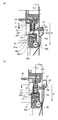
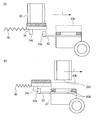
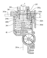
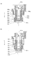
도 1은 실시예에 관한 폐토너 배출부의 본체부와의 결합을 설명하는 부분 단면도이다.
도 2는 실시예에 관한 전자 사진 화상 형성 장치의 개략을 설명하기 위한 도면이다.
도 3은 실시예에 관한 프로세스 카트리지의 개략 단면도이다.
도 4는 실시예에 관한 프로세스 카트리지 내의 폐토너의 흐름을 설명하는 단면도이다.
도 5는 실시예에 관한 제거 토너의 반송 경로를 나타내는 개략 단면도이다.
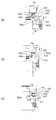
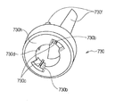
도 6은 실시예에 관한 프로세스 카트리지의 사시도이다.
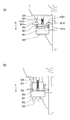
도 7은 실시예에 관한 프로세스 카트리지의 반송 스크류의 단면 위치를 설명하는 단면도이다.
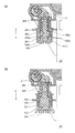
도 8은 실시예에 관한 프로세스 카트리지의 반송 스크류와 커플링의 결합 설명도이다.
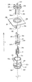
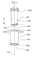
도 9는 실시예에 관한 프로세스 카트리지의 폐토너 배출부의 구성 설명도이다.
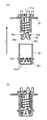
도 10은 실시예에 관한 프로세스 카트리지의 폐토너 배출부 단면이다.
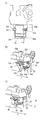
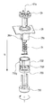
도 11은 실시예에 관한 폐토너 연결 부재의 조립 설명도이다.
도 12는 실시예에 관한 폐토너 배출부의 구동 연결 구성을 설명하는 부품도이다.
도 13은 실시예에 관한 화상 형성 장치로의 프로세스 카트리지 삽입 방향을 나타내는 도면이다.
도 14는 실시예에 관한 다른 구성의 커플링을 설명하는 사시도이다.
도 15는 실시예에 관한 폐토너 반송 핀의 사시도이다.
도 16은 실시예에 관한 폐토너 배출부의 접속 방법을 설명하는 사시도이다.
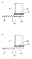
도 17은 실시예에 관한 폐토너 배출구의 셔터 구성을 설명하는 사시도이다.
도 18은 실시예에 관한 장치 본체 장착 시의 폐토너 배출부의 셔터의 움직임을 설명하는 단면도이다.
도 19는 실시예에 관한 장치 본체의 앞문을 연 상태를 설명하는 사시도이다.
도 20은 실시예에 관한 장치 본체의 카트리지 아래 가이드의 형상을 설명하는 단면도이다.
도 21은 실시예에 관한 프로세스 카트리지의 장치 본체 장착 궤적을 설명하는 단면도이다.
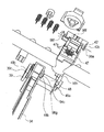
도 22는 실시예에 관한 프로세스 카트리지의 장착 방향 안쪽 구성을 설명하는 사시도이다.
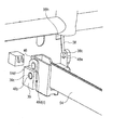
도 23은 실시예에 관한 장치 본체의 프로세스 카트리지 장착 방향 안쪽 구성을 설명하는 부분 사시도이다.
도 24는 실시예에 관한 장치 본체 안쪽의 삽입 완료까지의 프로세스 카트리지의 움직임을 나타내는 모식도이다.
도 25는 실시예에 관한 암과 앞문의 링크 구성을 설명하는 단면 모식도이다.
도 26은 실시예에 관한 장착 방향 안쪽의 앞문 링크 부품의 지지 구성을 설명하는 사시도이다.
도 27은 실시예에 관한 장착 방향 안쪽의 앞문 링크 부품의 지지 구성을 설명하는 다른 방향으로부터의 사시도이다.
도 28은 실시예에 관한 앞문 열림 시의 장착 방향 앞쪽의 앞문 링크 부품의 지지 구성을 설명하는 사시도이다.
도 29는 실시예에 관한 다른 구성에서의 현상 롤러로부터 폐토너 배출부로의 구동 연결 구성을 설명하는 부품도이다.
도 30은 실시예에 관한 다른 구성에서의 반송 핀으로의 구동 전달을 설명하는 단면도이다.
도 31은 실시예 2에 관한 폐토너 배출부를 셔터로 닫은 상태를 설명하는 단면도이다.
도 32는 실시예 2에 관한 셔터와 탄성 시일 부재의 분해 사시도이다.
도 33은 실시예 2에 관한 셔터가 폐토너 배출부를 닫을 때의 관계를 설명하는 셔터측에서 본 개략 모식도이다.
도 34는 실시예 3에 관한 장치 본체 장착 시의 폐토너 배출부의 셔터의 움직임을 설명하는 단면도이다.
도 35는 실시예 3에 관한 폐토너 연결 부재와 셔터의 위치 관계를 나타내는 사시도이다.
도 36은 실시예 3에 관한 폐토너 연결 부재의 벽부와 셔터의 위치 관계를 나타내는 측면도이다.
도 37은 실시예 3에 관한 본체 구성을 나타내는 외관도.
도 38은 실시예 3에 관한 본체와 카트리지의 결합을 설명하는 단면도.
도 39는 실시예 3에 관한 프로세스 카트리지의 삽입 동작을 나타내는 장착도.
도 40은 실시예 3에 관한 스프링 누름으로부터 본체 받아들임 시일 부재 및 세로 시일을 떼어낸 본체 폐토너 받아들임입구의 외관도.
도 41은 본체 반송 핀의 다른 구성을 나타내는 외관도.
도 42는 실시예 4에 관한 반송 스크류로부터 제1 커플링으로의 구동 전달 구성을 설명하는 개략도.
도 43은 실시예 5에 관한 폐토너 연결부의 부품 구성을 설명하는 분해도.
도 44는 실시예 5에 관한 본 구성의 폐토너 연결부의 부품 구성을 설명하는 단면도.
도 45는 실시예 5에 관한 폐토너 연결부의 장치 본체와의 연결 방법을 설명하는 카트리지 장착도.
도 46은 실시예 6에 관한 각 부품을 설명하는 분해도.
도 47은 실시예 6에 관한 폐토너 연결부의 장치 본체와의 연결 방법을 설명하는 장착 단면도.
도 48은 실시예 7에 관한 폐토너 연결부와, 그 외의 부품의 장착을 설명하는 분해도.
도 49는 실시예 7에 관한 제2 커플링의 형상을 설명하는 외관도, 도 50은 본 실시예의 장치 본체(100)와의 연결을 설명하는 단면도.
도 50은 실시예 7에 관한 장치 본체(100)와의 연결을 설명하는 단면도.
도 51은 실시예 8에 관한 폐토너 연결부와 그 외의 부품의 장착을 설명하는 분해도.
도 52는 실시예 8에 관한 제2 커플링의 형상을 설명하는 외관도.
도 53은 실시예 8에 관한 연결 동작부의 형상을 설명하는 외관도.
도 54는 실시예 8에 관한 폐토너 배출구 부근의 본체 접속 전후의 카트리지 단면도.
도 55는 실시예 8에 관한 폐토너 배출구 부근의 본체 접속 전후의 카트리지 측면도.
도 56은 실시예 8에 관한 장치 본체로의 토너 배출구의 결합을 설명하는 외관도.
도 57은 실시예 8에 관한 프로세스 카트리지의 토너 배출구로부터의 토너 배출 경로를 설명하는 단면도.
도 58은 실시예 8에 관한 프로세스 카트리지의 장치 본체와의 결합 방법을 설명하는 단면도.
도 59는 실시예 8에 관한 프로세스 카트리지의 장치 본체와의 결합 방법을 설명하는 부분 개략도.FIG. 1 is a partial cross-sectional view for explaining a connection of the waste toner discharge portion with the main body portion according to the embodiment.
2 is a diagram for explaining the outline of an electrophotographic image forming apparatus according to the embodiment.
3 is a schematic cross-sectional view of the process cartridge according to the embodiment.
4 is a cross-sectional view illustrating the flow of waste toner in the process cartridge according to the embodiment.
5 is a schematic cross-sectional view showing a conveying path of the removed toner according to the embodiment.
6 is a perspective view of the process cartridge according to the embodiment.
7 is a cross-sectional view for explaining the position of the cross section of the conveyance screw of the process cartridge according to the embodiment.
8 is an explanatory view showing the combination of the conveyance screw and the coupling of the process cartridge according to the embodiment.
9 is a configuration explanatory view of a waste toner discharging portion of the process cartridge according to the embodiment.
10 is a cross section of a waste toner discharge portion of the process cartridge according to the embodiment.
FIG. 11 is an explanatory view of assembling the waste toner connecting member according to the embodiment. FIG.
12 is a part for explaining the drive connection configuration of the waste toner discharge portion according to the embodiment.
13 is a view showing a process cartridge insertion direction in the image forming apparatus according to the embodiment.
Fig. 14 is a perspective view for explaining coupling of another configuration according to the embodiment. Fig.
15 is a perspective view of a waste toner conveying pin according to the embodiment.
16 is a perspective view for explaining a connection method of the waste toner discharge portion according to the embodiment.
17 is a perspective view for explaining a shutter configuration of the waste toner outlet according to the embodiment.
18 is a cross-sectional view for explaining the movement of the shutter of the waste toner discharging portion when the apparatus main body is mounted according to the embodiment.
19 is a perspective view for explaining a state in which the front door of the apparatus main body according to the embodiment is opened.
20 is a cross-sectional view for explaining the shape of the guide under the cartridge of the apparatus main body according to the embodiment.
21 is a cross-sectional view for explaining the apparatus main assembly mounting locus of the process cartridge according to the embodiment.
Fig. 22 is a perspective view for explaining the inner configuration of the process cartridge in the mounting direction according to the embodiment. Fig.
23 is a partial perspective view for explaining the inner configuration of the process cartridge mounting direction of the apparatus main body according to the embodiment.
24 is a schematic view showing the movement of the process cartridge until the insertion of the inside of the apparatus main body according to the embodiment is completed.
25 is a schematic cross-sectional view for explaining the link structure of the arm and the front door according to the embodiment.
26 is a perspective view for explaining a supporting structure of a front door link part inside the mounting direction according to the embodiment.
Fig. 27 is a perspective view from a different direction for explaining a supporting structure of a front door link part inside the mounting direction according to the embodiment. Fig.
28 is a perspective view for explaining a support structure of a front door link component in front of the front door in the mounting direction according to the embodiment;
Fig. 29 is a view for explaining a driving connection configuration from the developing roller to the waste toner discharging portion in another configuration relating to the embodiment; Fig.
30 is a cross-sectional view for explaining drive transmission to a conveying pin in another configuration related to the embodiment.
31 is a sectional view for explaining a state in which the waste toner discharging portion according to the second embodiment is closed by a shutter.
32 is an exploded perspective view of the shutter and the elastic seal member according to the second embodiment.
Fig. 33 is a schematic view schematically showing the relationship of the shutter according to the second embodiment when the waste toner discharging portion is closed, viewed from the shutter side; Fig.
34 is a cross-sectional view for explaining the movement of the shutter of the waste toner discharging portion at the time of mounting the apparatus main body according to the third embodiment;
35 is a perspective view showing the positional relationship between the waste toner connecting member and the shutter according to the third embodiment;
36 is a side view showing the positional relationship between the wall portion of the waste toner connecting member and the shutter according to the third embodiment;
37 is an external view showing a configuration of a main body according to a third embodiment;
38 is a cross-sectional view for explaining the coupling between the main assembly and the cartridge according to the third embodiment;
39 is a mounting view showing the insertion operation of the process cartridge according to the third embodiment;
Fig. 40 is an external view of a main body waste toner receiving member inlet and a main body waste toner receiving member, from which the main body receiving seal member and the vertical seal are removed from the spring pressing according to
41 is an external view showing another configuration of the main body conveying pin;
42 is a schematic view for explaining a drive transmission configuration from a conveyance screw to a first coupling according to
43 is an exploded view for explaining a component configuration of a waste toner connection portion according to
44 is a cross-sectional view for explaining a component configuration of a waste toner connection portion according to the fifth embodiment of the present invention;
45 is a cartridge mounting view for explaining a connection method of the waste toner connection portion with the apparatus main body according to
46 is an exploded view for explaining each component according to the sixth embodiment;
47 is a mounting sectional view for explaining a connection method of the waste toner connection portion with the apparatus main body according to Embodiment 6;
48 is an exploded view for explaining mounting of a waste toner connecting portion according to
Fig. 49 is an external view for explaining the shape of the second coupling according to the seventh embodiment, and Fig. 50 is a sectional view for explaining connection with the apparatus
50 is a sectional view for explaining connection with the apparatus
51 is an exploded view for explaining mounting of a waste toner connecting portion and other parts according to Embodiment 8. Fig.
52 is an external view illustrating the shape of the second coupling according to the eighth embodiment;
53 is an external view for explaining the shape of the connecting operation portion according to the eighth embodiment;
54 is a sectional view of the cartridge before and after connection of the main body in the vicinity of the waste toner outlet according to the eighth embodiment;
55 is a side view of the cartridge before and after connection of the main body in the vicinity of the waste toner outlet according to the eighth embodiment;
56 is an external view for explaining the engagement of the toner discharge port to the apparatus main body according to Embodiment 8. Fig.
57 is a sectional view for explaining a toner discharge path from the toner discharge port of the process cartridge according to Embodiment 8. Fig.
58 is a cross-sectional view for explaining a method of coupling the process cartridge with the apparatus main body according to the eighth embodiment;
59 is a partial schematic view for explaining a method of coupling the process cartridge with the apparatus main body according to the eighth embodiment;
<실시예 1>≪ Example 1 >
이하, 본 실시예의 화상 형성 장치 및 프로세스 카트리지에 대해 도면을 이용하여 설명한다. 화상 형성 장치란, 예를 들면 전자 사진 화상 형성 프로세스를 이용하여 기록 매체에 화상을 형성하는 것이다. 예를 들면, 전자 사진 복사기, 전자 사진 프린터(예를 들면, LED 프린터, 레이저 빔 프린터 등), 전자 사진 팩시밀리 장치 등이 포함된다. 또한, 프로세스 카트리지란, 감광체, 감광체 상에 형성된 잠상을 현상하는 현상 수단 등을 가지고, 전자 사진 화상 형성 장치 본체(이하, 장치 본체)에 착탈 가능한 것을 지칭한다. 또한, 프로세스 카트리지에 사용되는 감광체 드럼과 커플링 부재 등을 일체화한 것을 드럼 유닛이라 부른다.Hereinafter, the image forming apparatus and the process cartridge of the present embodiment will be described with reference to the drawings. An image forming apparatus is an apparatus for forming an image on a recording medium by using, for example, an electrophotographic image forming process. For example, an electrophotographic copying machine, an electrophotographic printer (for example, an LED printer, a laser beam printer, etc.), an electrophotographic facsimile machine, and the like. Further, the process cartridge refers to a cartridge which has a photoconductor, a developing means for developing a latent image formed on the photoconductor, and the like, which can be attached to and detached from the main body of the electrophotographic image forming apparatus (hereinafter referred to as the apparatus main body). A drum unit in which the photosensitive drum and the coupling member used in the process cartridge are integrated is called a drum unit.
또한, 이하의 실시예에서는 4개의 프로세스 카트리지가 착탈 가능한 풀 컬러 화상 형성 장치를 예시하고 있다. 그러나, 화상 형성 장치에 장착하는 프로세스 카트리지의 개수는 이에 한정되는 것은 아니다. 또한, 마찬가지로, 실시예에서 개시하는 각 구성에 대하여, 특히 한정적인 기재를 하지 않는 한, 재질, 배치, 치수, 그 밖의 수치 등을 한정하는 것은 아니다. 또한, 특히 명기하지 않는 한, 위쪽이란 화상 형성 장치를 설치했을 때의 중력 방향 위쪽을 가리키는 것으로 한다.In the following embodiments, a full-color image forming apparatus in which four process cartridges are detachable is exemplified. However, the number of process cartridges to be mounted in the image forming apparatus is not limited to this. Likewise, the materials, arrangement, dimensions, other numerical values, and the like are not limited to the respective constitutions disclosed in the embodiments, unless otherwise specified. Unless otherwise specified, the upper side refers to the upper direction of gravity when the image forming apparatus is installed.
§1. [화상 형성 장치의 개략 설명]§One. [Outline of image forming apparatus]
이하에서, 본 실시예의 화상 형성 장치의 화상 형성에 관한 동작과, 폐토너의 반송에 대하여 간단히 설명한다.Hereinafter, an operation related to image formation of the image forming apparatus of the present embodiment and the conveyance of waste toner will be briefly described.
(화상 형성 장치 본체에 대하여)(Regarding the image forming apparatus main body)
우선, 본 실시예와 관련되는 전자 사진 화상 형성 장치(화상 형성 장치)의 일 실시예의 전체 구성에 대하여, 도 2, 도 3, 도 4, 도 5를 이용하여 설명한다. 도 2는 본 실시예의 화상 형성 장치(100)의 개략 단면도, 도 3은 프로세스 카트리지의 주 단면도이다. 도 4는 프로세스 카트리지(7)의 폐토너 배출 구성을 나타내는 개략 단면도이다. 또한, 도 5는 장치 본체(100)의 폐토너의 반송 경로를 나타내는 배면 모식도이다.First, the overall configuration of an embodiment of an electrophotographic image forming apparatus (image forming apparatus) according to the present embodiment will be described with reference to Figs. 2, 3, 4, and 5. Fig. Fig. 2 is a schematic cross-sectional view of the
도 2에 도시하는 바와 같이, 화상 형성 장치(100)는 복수의 화상 형성부를 구비한다. 구체적으로는, 옐로우(Y), 마젠타(M), 시안(C), 블랙(K)의 각 색의 화상을 형성하기 위한 제1, 제2, 제3, 제4 화상 형성부(SY, SM, SC, SK)를 갖는다. 본 실시예에서는, 제1 내지 제4 화상 형성부(SY, SM, SC, SK)는, 연직 방향과 교차하는 방향으로 일렬로 배치되고 있다.As shown in Fig. 2, the
또한 본 실시예에서는, 제1 내지 제4 화상 형성부의 구성 및 동작은, 형성하는 화상의 색이 다른 것을 제외하고 실질적으로 동일하다. 따라서, 이하, 특히 구별을 필요로 하지 않는 경우는, Y, M, C, K는 생략하여 총괄적으로 설명한다.Further, in this embodiment, the configurations and operations of the first to fourth image forming portions are substantially the same except that the colors of the images to be formed are different. Therefore, in the following description, Y, M, C, and K are omitted and are collectively described when no particular distinction is required.
즉, 본 실시예에서는, 화상 형성 장치(100)는, 4개의 감광체 드럼(1)(1Y, 1M, 1C, 1K)을 갖는다. 감광체 드럼(1)은, 도시한 화살표 A 방향으로 회전한다. 감광체 드럼(1)의 주위에는 대전 롤러(2) 및 스캐너 유닛(노광 장치)(3)이 배치되어 있다.That is, in this embodiment, the
여기서, 대전 롤러(2)는, 감광체 드럼(1)의 표면을 균일하게 대전하는 대전 수단이다. 그리고, 스캐너 유닛(3)은, 화상 정보에 기초하여 레이저를 조사해 감광체 드럼(1) 상에 정전상(정전 잠상)을 형성하는 노광 수단이다. 또한, 감광체 드럼(1)의 주위에는, 현상 장치(이하, 현상 유닛)(4)(4Y, 4M, 4C, 4K) 및 클리닝 수단(클리닝 부재)으로서의 클리닝 블레이드(6)(6Y, 6M, 6C, 6K)가 배치되어 있다.Here, the charging
또한, 4개의 감광체 드럼(1)에 대향하여, 감광체 드럼(1) 상의 토너상을 기록재(12)로 전사하기 위한 중간 전사체로서의 중간 전사 벨트(5)가 배치되고 있다.An
또한, 본 실시예에서는, 현상 유닛(4)은, 현상제로서 비자성 일성분 현상제, 즉, 토너(T)를 사용한다. 또한, 본 실시예에서는, 현상 유닛(4)은, 현상제 담지체로서의 현상 롤러(17)를 감광체 드럼(1)에 대해 접촉시켜 접촉 현상을 행하는 것이다.Further, in this embodiment, the developing
본 실시예에서는, 클리닝 유닛(13)은, 감광체 드럼(1)과, 대전 롤러(2), 클리닝 부재로서의 클리닝 블레이드(6)를 갖는다. 또한, 클리닝 블레이드(6)에 의해 제거된 감광체 드럼(1) 상에 잔류하고 있던 전사 잔류 토너(폐토너)를 수용하는 수납부로서의 폐토너 수용부(14a)(14aY, 14aM, 14aC, 14aK)를 갖는다.In this embodiment, the
나아가 본 실시예에서는, 현상 유닛(4) 및 클리닝 유닛(13)을 일체적으로 카트리지화하여, 프로세스 카트리지(7)를 형성하고 있다. 프로세스 카트리지(7)는, 화상 형성 장치 본체에 설치된 도시하지 않은 장착 가이드, 위치 결정 부재 등의 장착 수단(가이드, 안내 기구)을 거쳐, 화상 형성 장치(100)에 착탈 가능하게 되어 있다.Further, in the present embodiment, the developing
본 실시예에서는, 각 색용의 프로세스 카트리지(7)는 모두 동일 형상을 갖고 있다. 각 색용의 프로세스 카트리지(7) 내에는, 각각 옐로우(Y), 마젠타(M), 시안(C), 블랙(K)의 각 색의 토너(T)(TY, TM, TC, TK)가 수용되어 있다.In the present embodiment, the
중간 전사 벨트(5)는, 모든 감광체 드럼(1)에 접촉하여, 도시한 화살표 B 방향으로 회전한다. 중간 전사 벨트(5)는, 복수의 지지 부재(구동 롤러(87), 2차 전사 대향 롤러(88), 종동 롤러(89))에 걸쳐져 있다.The
중간 전사 벨트(5)의 내주면 측에는, 각 감광체 드럼(1)에 대향하도록, 1차 전사 수단으로서의 4개의 1차 전사 롤러(8)(8Y, 8M, 8C, 8K)가 나란히 설치되어 있다. 또한, 중간 전사 벨트(5)의 외주면 측에서 2차 전사 대향 롤러(88)에 대향하는 위치에는, 2차 전사 수단으로서의 2차 전사 롤러(9)가 배치되어 있다.Four primary transfer rollers 8 (8Y, 8M, 8C and 8K) as primary transfer means are provided side by side on the inner circumferential surface side of the
화상 형성 시에는, 우선, 감광체 드럼(1)의 표면이 대전 롤러(2)에 의해 균일하게 대전된다. 이어서, 스캐너 유닛(3)으로부터 내보내어진 화상 정보에 따른 레이저 광에 의해, 대전한 감광체 드럼(1)의 표면이 주사 노광된다. 이에 의해, 감광체 드럼(1) 상에 화상 정보에 따른 정전 잠상이 형성된다. 이어서, 감광체 드럼(1) 상에 형성된 정전 잠상은, 현상 유닛(4)에 의해 토너상으로서 현상된다. 즉 감광체 드럼(1)은, 그 표면에 토너로 형성된 상(토너상)을 담지하는 회전체(상 담지체)이다.At the time of image formation, first, the surface of the
감광체 드럼(1) 상에 형성된 토너상은, 1차 전사 롤러(8)의 작용에 의해 중간 전사 벨트(5) 상으로 전사(1차 전사)된다.The toner image formed on the
예를 들면, 풀 컬러 화상의 형성 시에는, 전술한 프로세스가 제1 내지 제4 화상 형성부(SY, SM, SC, SK)에서 순차로 행해진다. 각 화상 형성부에서 형성된 토너상은, 중간 전사 벨트(5) 상에 순차로 중첩시켜 1차 전사된다. 그 후, 중간 전사 벨트(5)의 이동과 동기하여 기록재(12)가 2차 전사부로 반송된다. 그리고, 기록재(12)를 통해 중간 전사 벨트(5)에 접촉하고 있는 2차 전사 롤러(9)의 작용에 의해, 중간 전사 벨트(5) 상의 4색 토너상은 일괄하여 기록재(12) 상으로 2차 전사된다.For example, at the time of forming a full color image, the above-described process is sequentially performed in the first to fourth image forming sections SY, SM, SC, and SK. The toner images formed in the respective image forming portions are sequentially superimposed on the
토너상이 전사된 기록재(12)는, 정착 수단으로서의 정착 장치(10)로 반송된다. 정착 장치(10)에서 기록재(12)에 열 및 압력을 가함으로써, 기록재(12)에 토너상이 정착된다. 또한, 1차 전사 공정 후에 감광체 드럼(1) 상에 잔류한 1차 전사 잔류 토너는, 클리닝 부재로서의 클리닝 블레이드(6)에 의해 제거되어 회수된다.The
또한, 화상 형성 장치로부터 카트리지와 같이 착탈 자유롭게 설치된 유닛을 제외한 부위를 화상 형성 장치 본체(장치 본체)라고 지칭하여, 화상 형성 장치와 구별하는 경우도 있다.In addition, a portion of the image forming apparatus excluding the units detachably mounted, such as a cartridge, from the image forming apparatus may be referred to as an image forming apparatus main body (apparatus main body) and may be distinguished from the image forming apparatus.
(인쇄 중의 폐토너 반송에 대하여)(Concerning waste toner transportation during printing)
이하에서, 회수된 폐토너의 반송에 대해 설명한다. 클리닝 블레이드에 의해 상 담지체(감광체 드럼(1)) 상으로부터 회수된 폐토너는, 수납부로서의 폐토너 수용부(14a)(14aY, 14aM, 14aC, 14aK)에 수용된다. 폐토너 수용부(14a)는 카트리지측에서 일시적으로 폐토너를 수용하는 수용부로서의 기능을 갖는다.Hereinafter, the conveyance of the recovered waste toner will be described. The waste toner collected from the image carrier (photosensitive drum 1) by the cleaning blade is accommodated in the waste
폐토너 수용부(14a)의 제1 반송로(51)(51Y, 51M, 51C, 51K) 내에 반송 부재(카트리지측 반송 부재)로서의 반송 스크류(26)(도 3 참조)가 배치되어 있다. 이에 의해, 폐토너 수용부(14a)에 회수된 폐토너는 카트리지측 반송 부재로서의 반송 스크류(26)에 의해, 프로세스 카트리지(7)의 길이 방향 일단 측으로 반송된다. 또한, 프로세스 카트리지(7)의 길이 방향은 감광체 드럼(1)의 회전축선이나, 반송 스크류(26)의 회전축선과 대략 평행한 방향이다. 따라서 특히 달리 언급하지 않는 경우에는, 프로세스 카트리지의 길이 방향과, 감광체 드럼(1)의 회전축선 방향과, 반송 스크류(26)의 회전축선 방향을 동일한 것으로 간주한다. 또한, 회전축선 방향(축선 방향)이란, 회전체의 회전축선 및 그 회전축선에 평행한 직선이 연장하고 있는 방향이다.A conveying screw 26 (see Fig. 3) as a conveying member (cartridge side conveying member) is disposed in the first conveying path 51 (51Y, 51M, 51C, 51K) of the waste
반송된 폐토너는 제2 반송로(61)(도 4 참조)를 통해, 장치 본체의 폐토너 받아들임입구(토너 받아들임입구)(80d)로 반송된다. 또한 제2 반송로(61)는 배출구(폐토너 배출부)(32d)를 향해 토너를 이동시키는 배출로이다. 배출구(32d)로부터 배출된 토너가 폐토너 받아들임입구(80d)로 진입한다.The conveyed waste toner is conveyed to the waste toner acceptance inlet (toner acceptance inlet) 80d of the apparatus main body through the second conveying path 61 (see Fig. 4). The second conveying
제2 반송로(61)는, 감광체 드럼(1)의 회전축선 방향에서, 카트리지의 일단 측에 배치되어 있다. 제2 반송로(61)는, 축선 방향에 교차하는 방향(본 실시예에서는 축선 방향과 거의 직교하는 방향)으로 토너를 이동시킨다.The second conveying
제2 반송로(61)에는, 제1 커플링 부재(29), 커플링 스프링(31), 제2 커플링 부재(30), 폐토너 연결 부재(32)가 설치되어 있다. 이 때, 폐토너 연결 부재(32)는 프로세스 카트리지(7)에 대하여 중심선(61a)을 따라 이동 가능하게 지지되고 있다. 폐토너 연결 부재(32)는 제2 반송로(61)의 종단을 구성하는 부재이며, 토너를 카트리지의 외부로 배출하기 위한 배출구(32d)를 갖는다. 또한 자세한 것은 후술하지만, 폐토너 연통 부재(32)는, 배출구(32)를, 화상 형성 장치 본체에 설치된 토너 받아들임입구(80d)에 접속, 연결시킬 수 있도록 이동하는 연결부이다.A
또한, 제2 커플링 부재(30)는 카트리지의 내부로부터 외부로 구동력(회전력)을 전달시키기 위한 커플링 부재이다.The
자세한 것은 후술하지만, 이 폐토너 연결 부재(32)는, 프로세스 카트리지(7)의 화상 형성 장치로의 장착 동작에 따라 이동한다. 적어도 화상 형성을 행할 때에, 폐토너 연결 부재(32)는 본체 폐토너 받아들임입구(80d)와 연결된 상태가 된다. 또한, 프로세스 카트리지(7)를 화상 형성 장치에 장착한 상태에 있어서의 중력 방향과 중심선(61a)은 대략 평행이 된다.The waste
폐토너는 폐토너 받아들임입구(80d)로부터 스프링 커플링(44), 반송 핀(45)을 통과하여, 제2 반송로(80b)로 보내진다. 자세한 것은 후술하지만, 스프링 커플링(44) 및 반송 핀은, 장치 본체 측의 반송 부재(본체측 반송 부재)이며, 토너를 폐토너 박스(86)을 향해 반송하도록 구성되어 있다.The waste toner is sent from the waste
스프링 커플링(44) 및 반송 핀에 의해 반송된 토너는, 그 후, 제2 반송로(80b) 내에 설치된 본체 반송 스크류(85)에 의해 화상 형성 장치의 본체측 토너 수납부로서의 폐토너 박스(86)(도 5 참조)에 배출, 수용된다. 또한, 제1 본체측 반송 부재로서의 반송 핀(45)(및 스프링 커플링(44))에 의해, 폐토너는 제2 본체측 반송 부재로서 본체측 반송 스크류(85)를 향해 반송된다. 또한, 본체측 반송 스크류(85)는, 장치 본체에 설치된 구동원으로서의 모터로부터의 구동력을 받아 회전 가능하게 설치되어 있다. 또한, 반송 핀(45)은 카트리지에 설치된 회전하여 구동력을 전달하는 부위와 결합하여 회전함으로써 폐토너를 반송 가능하도록 구성되어 있다.The toner conveyed by the
폐토너의 반송부에 대해서는 이후에 상세히 설명한다.The conveying portion of the waste toner will be described later in detail.
또한, 2차 전사 공정 후에 중간 전사 벨트(5) 상에 잔류한 2차 전사 잔류 토너는, 중간 전사 벨트 클리닝 장치(11)(도 2 참조)에 의해 제거된다. 또한, 화상 형성 장치(100)는, 원하는 단독 또는 몇 개(전부는 아님)의 화상 형성부만을 이용하여, 단색 또는 멀티 컬러의 화상을 형성하는 것도 가능하도록 되어 있다.The secondary transfer residual toner remaining on the
§2. [프로세스 카트리지에 대해]§2. [About process cartridges]
다음으로, 본 실시예의 화상 형성 장치(100)에 장착되는 프로세스 카트리지(7)의 전체 구성에 대해, 도 3, 도 6을 이용하여 설명한다. 도 6은 현상 유닛(4)과 클리닝 유닛(13)을 나타내는 분해 사시도이다. 프로세스 카트리지(7)는 현상 장치(4), 클리닝 유닛(13)이 일체가 되어 형성되어 있다. 도 6에 도시하는 바와 같이, 현상 유닛(4)은, 베어링 부재(19R, 19L)에 설치된, 구멍(19Ra, 19La)을 구비한다. 또한, 클리닝 유닛(13)은, 클리닝 유닛(13)의 프레임에 설치된 구멍(13a)(13aR, 13aL, 도 6 참조)을 구비한다. 그리고, 현상 유닛(4)과 클리닝 유닛(13)은, 구멍(19Ra, 19La)과 구멍(13aR, 13aL)에 감합(嵌合)하는 축(24)(24R, 24L)을 중심으로 회동 자유롭게 결합되고 있다. 또한, 현상 유닛(4)은 가압 스프링(25)에 의해 가압되고 있다. 그 때문에, 프로세스 카트리지(7)의 화상 형성 시에 있어서는, 현상 유닛(4)은 축(24)을 중심으로 도 3에 도시한 화살표 F 방향으로 회전하여, 감광체 드럼(1)과 현상 롤러(17)는 접촉한다. 현상 롤러(17)는, 그 표면에 토너(현상제)를 담지하여 회전하는 회전체(현상제 담지체, 현상 부재)이다. 현상 롤러(17)는, 감광체 드럼(1)에 토너를 공급함으로써 감광체 드럼(1)의 잠상을 현상한다.Next, the overall structure of the
(현상 유닛에 대하여)(With respect to the developing unit)
다음으로, 본 실시예의 프로세스 카트리지(7)와 관련되는 현상 장치(4)에 대해 도 3, 도 6을 이용하여 설명한다.Next, the developing
도 3, 도 6에 도시하는 바와 같이, 현상 유닛(4)은 현상 유닛(4) 내의 각종 요소를 지지하는 현상 프레임(18)을 갖는다. 현상 유닛(4)에는, 감광체 드럼(1)과 접촉하여 도시한 화살표 D 방향(반시계 방향)으로 회전하는 현상제 담지체로서의 현상 롤러(17)가 설치되고 있다. 현상 롤러(17)는, 그 길이 방향(회전축선 방향)의 양 단부에서, 현상 베어링(19)(19R, 19L)을 개재하여, 회전 가능하게 현상 프레임(18)에 지지되고 있다. 여기서, 현상 베어링(19)(19R, 19L)은, 현상 프레임(18)의 양 측부에 각각 장착되고 있다.As shown in Figs. 3 and 6, the developing
또한, 현상 유닛(4)은, 도 3에 도시하는 바와 같이, 현상제 수납실(이하, 토너 수납실)(18a)과, 현상 롤러(17)가 배치된 현상실(18b)을 갖는다.3, the developing
현상실(18b)에는, 현상 롤러(17)에 접촉하여 화살표 E 방향으로 회전하는 현상제 공급 부재로서의 토너 공급 롤러(20)와, 현상 롤러(17)의 토너층을 규제하기 위한 현상제 규제 부재로서의 현상 블레이드(21)가 배치되어 있다. 토너 공급 롤러(20)는 현상 롤러(17)에 토너를 공급하는 롤러이다. 토너 공급 롤러(20)는 그 표면에 토너를 담지하여 회전하는 회전체이며, 토너 공급 부재이다.The developing
현상 블레이드(21)는, 지지 부재(22)에 대해, 예를 들면 용접되어 일체화되어 있다. 또한, 현상 프레임(18)의 토너 수납실(18a)에는, 수용된 토너를 교반함과 함께 상기 토너 공급 롤러(20)로 토너를 반송하기 위한 교반 부재(23)가 설치되어 있다.The developing
(클리닝 유닛에 대하여)(For the cleaning unit)
다음으로, 본 실시예의 프로세스 카트리지(7)와 관련되는 클리닝 유닛(13)에 대해 도 3, 도 6을 이용하여 설명한다.Next, the
클리닝 유닛(13)은, 클리닝 유닛(13) 내의 각종 요소를 지지하는 프레임으로서의 클리닝 프레임(14)을 갖는다. 클리닝 프레임(14)에는, 베어링 부재(27)(27R 및 27L, 도 6 참조)를 개재하여 감광체 드럼(1)이 도 3에 도시한 화살표 A 방향으로 회전 가능하게 장착되고 있다. 또한, 클리닝 블레이드(6)는, 도 3에 도시하는 바와 같이, 1차 전사 후에 감광체 드럼(1)의 표면에 남은 전사 잔류 토너(폐토너)를 제거하기 위한 탄성 부재(6a)와, 탄성 부재를 지지하기 위한 지지 부재(6b)가 일체로 형성되고 있다. 클리닝 블레이드(6)는, 감광체 드럼(1)의 길이 방향의 양 단부를 클리닝 프레임(14)에 비스 등의 수단으로 고정되고 있다.The
클리닝 블레이드(6)에 의해 감광체 드럼(1)의 표면으로부터 제거된 폐토너는, 클리닝 블레이드(6)와, 클리닝 프레임(14)에 의해 형성되는 공간을 중력 방향으로 낙하하여, 폐토너 수용부(14a) 내에 일시적으로 수용된다. 또한, 클리닝 프레임(14)에는, 대전 롤러 베어링(15)이 대전 롤러(2)의 회전 중심과 감광체 드럼(1)의 회전 중심을 통과하는 선을 따라 장착되고 있다.The waste toner removed from the surface of the
여기서, 대전 롤러 베어링(15)은, 도 3에 나타내는 화살표 C 방향으로 이동 가능하게 장착되어 있다. 대전 롤러(2)의 회전축(2a)은, 대전 롤러 베어링(15)에 회전 가능하게 장착되고 있다. 그리고, 대전 롤러 베어링(15)은, 가압 수단으로서의 대전 롤러 가압 스프링(16)에 의해 감광체 드럼(1)을 향해 가압된다.Here, the charging
§3. [폐토너 반송부에 대하여]§3. [Regarding waste toner conveying section]
이하에서, 폐토너를 반송하는 반송부에 대하여 상세히 설명한다. 폐토너를 반송하는 폐토너 반송 장치가 화상 형성 장치의 안쪽 측에 설치되어 있는 구성에서는, 카트리지의 토너 배출구를 본체측 후측판의 안쪽까지 삽입하는 구성을 채용하는 것이 바람직하다. 그러나, 이러한 구성에서는, 카트리지의 일부를 후측판의 안쪽까지 삽입하기 위한 돌기를 구비하는 구성으로 할 수밖에 없다. 바꾸어 말하면, 전술한 구성에서는, 카트리지의 길이 방향의 폭을 짧게 하는 것이 어렵다.Hereinafter, the carrying unit for carrying waste toner will be described in detail. It is preferable to employ a configuration in which the waste toner conveying device for conveying the waste toner is provided on the inner side of the image forming apparatus so that the toner outlet of the cartridge is inserted to the inside of the back side panel of the main body side. However, in such a configuration, it is inevitable to provide a projection for inserting a part of the cartridge up to the inside of the rear side plate. In other words, in the above-described configuration, it is difficult to shorten the width in the longitudinal direction of the cartridge.
이 때문에, 본 실시예에서는 폐토너 반송 장치를 화상 형성 장치의 프로세스 카트리지(7)를 장착하는 공간에 배치하였다. 이에 의해, 프로세스 카트리지의 길이 방향의 폭이 넓어지는 것을 억제할 수 있다.Therefore, in the present embodiment, the waste toner conveying device is disposed in the space for mounting the
(폐토너 반송부의 개략에 대하여)(Regarding the Outline of the Waste Toner Carrying Unit)
다음으로, 클리닝 유닛(13)에 설치된 폐토너 배출부(40)의 배치 위치에 관하여, 도 4, 도 6을 이용하여 설명한다. 도 6에 도시하는 바와 같이, 폐토너 배출부(40)는, 감광체 드럼 축선 방향으로, 장착 부딪힘 위치(7m)보다 내측(영역 AA)에 배치되고 있다. 이에 의해, 장치 본체(100)의 후측판(98)의 프로세스 카트리지(7) 측에서 폐토너를 배출하는 구성으로 된다. 바꾸어 말하면, 화상 형성 장치의 프로세스 카트리지를 장착하기 위한 공간 중, 후측판의 근방에서 프로세스 카트리지(7)로부터 폐토너가 본체 측으로 전달되는 구성으로 되어 있다.Next, the arrangement position of the waste
계속하여, 폐토너 배출부(40)의 구성에 대해 도 3, 도 4를 이용하여 설명한다.Next, the configuration of the waste
감광체 드럼(1)은, 장치 본체(100)로부터의 구동을 받아 화살표 A 방향으로 회전한다. 감광체 드럼(1)의 회전은, 후술하는 기어열을 거쳐, 카트리지측 반송 부재로서의 폐토너 반송 스크류(26)로 전달된다. 폐토너 반송 스크류(26)는 클리닝 프레임(14)의 폐토너 수용부(14a)에 배치되어 있고, 화살표 G 방향으로 회전한다. 반송 스크류(26)는, 드럼(1)의 축선 방향을 따라 배치된 제1 반송로(51) 내의 폐토너를 프로세스 카트리지(7)의 길이 방향 일단 방향(도 4 화살표 H 방향)으로 반송한다.The
반송된 폐토너는, 제1 반송로(51)와 대략 직교하는 방향으로 설치된 제2 반송로(61)를 거쳐, 폐토너 연결 부재(32)에 설치된 개구부인 폐토너 배출부(배출구)(32d)로부터 장치 본체(100)의 도시하지 않은 폐토너 받아들임입구(80d)로 배출된다. 여기서, 폐토너 반송 스크류(26)는, 본 실시예에서는 스크류 형상이지만, 반송력을 가지는 비틀림 코일 스프링 형상이나, 불연속인 날개 형상을 갖는 다른 구성이어도 된다.The waste toner that has been conveyed passes through a second conveying
(반송로의 배치와 그 단면에 대하여)(Arrangement of conveying path and its cross section)
다음으로, 폐토너 반송 구성의 배치에 대해 도 3, 도 4, 도 7, 도 8, 도 12를 이용하여 설명한다. 도 7은, 반송 스크류(26)와 배출구(32d)의 위치 관계를 나타내는 개략도이다. 또한, 도 8은 프로세스 카트리지(7) 내에서의 반송 스크류(26)와 제1 커플링 부재(29)와의 결합을 중심선(61a) 방향으로부터 본 개략도이다.Next, the arrangement of the waste toner conveying configuration will be described with reference to Figs. 3, 4, 7, 8, and 12. Fig. 7 is a schematic view showing the positional relationship between the conveying
도 7(b)에 도시하는 바와 같이, 감광체 드럼(1)의 회전축선 방향을 따라 카트리지를 보았을 때, 제2 반송로(61)의 중심선(61a)이 폐토너 반송 스크류(26)의 축 중심과, 감광체 드럼(1)의 축 중심(1a)과의 사이를 통과하도록 제2 반송로(61)를 배치하였다. 즉, 중심선(61a)에 대하여 감광체 드럼(1)의 회전 중심(1a)과 제1 반송 부재(26)의 회전 중심은 서로 반대 측에 위치한다.The
또한, 중심선(61a)은, 제2 커플링 부재(30)의 회전 축선과 거의 동일한 직선이다. 즉, 감광체 드럼(1)의 회전 중심(1a)과 폐토너 반송 스크류(26)의 회전 중심은 제2 커플링 부재(30)의 회전축선(축선)에 대해 서로 반대 측에 있다.Further, the
상기와 같은 배치 관계를 만족함으로써, 감광체 드럼(1)이나 폐토너 반송 스크류(26)나, 제2 반송로(배출로)(61)를 작은 공간에 배치할 수 있다. 그 때문에, 클리닝 프레임(14)의 외형선 L(도 3 참조)로부터의 돌출량을 줄이거나 또는 없앨 수 있다. 그 때문에, 감광체 드럼(1)의 축선 방향으로부터 보았을 때의 클리닝 유닛 또는 프로세스 카트리지를 소형화할 수 있다.The
또한, 도 8(b)에 도시하는 바와 같이, 제2 반송로(61)의 중심선(61a) 방향으로부터 보아, 제2 반송로(61)의 개구부(61b)는, 반송 스크류(26)의 회전 시에 역 스크류부(26e)가 취할 수 있는 영역과 범위 K에 있어서 오버랩되도록 배치하고 있다.8 (b), the opening 61b of the second conveying
개구부(61b)는, 제1 반송로(51)와 제2 반송로(61)가 연통하는 연통부이다. 또한, 중심선(61a) 방향이란, 반송 스크류(26)의 축선과 대략 직교하는 방향이다. 즉, 반송 스크류(26)를 그 직교하는 방향을 따라 보면, 역 스크류부(26e)가 개구부(61b)에 겹쳐지게 된다.The opening 61b is a communicating portion in which the first conveying
이에 의해, 반송 스크류(26)의 반송력에 의해, 제1 반송로(51)로부터 제2 반송로(61)로 폐토너를 부드럽게 반송할 수 있다. 또한, 도 7(a)에 도시하는 바와 같이, 카트리지의 길이 방향(도 7(a)에서의 좌우 방향)에서 제1 반송로(51)와 제2 반송로(61)가 오버랩된다. 이에 의해, 폐토너의 반송에 필요한 반송로의 지름을 확보하면서, 클리닝 유닛(13)의 길이 방향의 폭을 줄일 수가 있다. 그 결과, 프로세스 카트리지(7)의 소형화가 가능해진다.Thereby, the waste toner can be smoothly conveyed from the first conveying
또한 역 스크류부(26e)는, 반송 스크류(26)의 제2 반송부로 간주할 수도 있다. 즉, 반송 스크류(26)는, 토너를 반송하기 위한 주요부인 제1 반송부(반송 스크류부(26a))와, 그 제1 반송부와는 반대 방향으로 토너를 반송하는 제2 반송부(역 스크류부(26e))를 갖는다(도 4 참조).The
반송 스크류(26)의 반송 스크류부(26a)는, 개구부(61b)를 향해 토너를 반송하기 위한 부분이다. 한편, 제2 반송부(역 스크류(26e))는, 반송 스크류부(26a)의 토너 반송 방향에 있어서, 반송 스크류부(26a)보다 하류 측에 배치되고 있는 부분이다. 제2 반송부인 역 스크류(26e)는 개구부(61b)의 근방에 배치되어 있고, 역 스크류(26e)의 길이는 제1 반송부에 비해 짧다.The conveying
또한, 도 4, 도 7에 도시하는 바와 같이, 베어링 부재(27)에는, 폐토너 배출부(40)로서, 제1 반송로(51)와 연통하고, 감광체 드럼(1)의 축선과 직교 방향으로 연신(延伸)한 제2 반송로(61)가 배치되고 있다. 제2 반송로(61)에는 배출구(32d)가 설치되어 있다.4 and 7, the bearing
제1 커플링 부재(29)는 제2 반송로(61)에 배치되고 있다. 또한, 제1 커플링 부재(29)는 중심선(61a)를 중심으로 하여 커플링 수용부(28)의 지지부(28b)에 회전 가능하게 지지된다. 도 8에 도시하는 바와 같이, 제1 커플링 부재(29)에는 구동 핀(29b)이 복수 설치되어, 반송 스크류(26)에 설치된 구동 전달 날개(26g)와 순차로 결합한다. 이 때문에, 반송 스크류(26)로부터 제1 커플링 부재(29)로 구동이 전달된다. 이렇게 하여, 감광체 드럼(1)의 회전 구동이, 감광체 드럼(1)의 축선과 직교 방향(제2 반송로(61)의 중심선(61a)) 중심의 회전으로 변환되어, 제1 커플링 부재(29)로 전달된다. 구동 전달 날개(26g)는 전술한 역 스크류(26e)를 구성하는 날개(나선부)이며, 제1 커플링 부재(29)는 역 스크류부(26e)로부터 구동력(회전력)이 전달되는 구성이다.The
(폐토너 배출구 부근의 상세 구성에 대하여)(Detailed configuration near the waste toner outlet)
다음으로, 프로세스 카트리지(7)의 제1 커플링 부재(29)로부터 배출구(32d)까지의 폐토너 반송부의 구성(폐토너 반송부(40))에 대해, 도 9, 도 10을 이용하여 설명한다.Next, the configuration of the waste toner conveying portion (waste toner conveying portion 40) from the
도 9는 폐토너 배출부의 구성을 설명하는 분해 개략도이다. 또한, 도 10은 커플링 수용부(28)로의 제1 커플링 부재(29), 제2 커플링 부재(30)의 장착를 설명하는 단면도이다. 감광체 드럼(1)으로부터 벗겨내진 전사 잔류 토너인 폐토너는, 제1 커플링 부재(29), 커플링 스프링(31), 제2 커플링 부재(30), 폐토너 연결 부재(32)를 거쳐 본체 받아들임입구(80d)로 반송된다. 또한, 자세한 것은 후술하지만, 폐토너 연결 부재(32)는 본체 받아들임입구(80d)와 연결 및 연결 해제가 가능한 구성으로 되어 있다.9 is an exploded schematic view for explaining the configuration of the waste toner discharging portion. 10 is a sectional view for explaining the mounting of the
여기서, 도 9에 도시하는 바와 같이, 제1 커플링 부재(29), 제2 커플링 부재(30), 커플링 스프링(31), 커플링 수용부(28), 폐토너 연결 부재(32)는 중심선(61a)을 따라 대략 동일 축선 상에 배치되고 있다. 또한, 제1 커플링 부재(29)와 제2 커플링 부재(30)는 커플링 스프링(31)으로 연결되고 있다. 폐토너 연결 부재(32)는, 커플링 수용부(28)에 대하여, 제2 커플링 부재(30)와 함께, 커플링 스프링(31)의 가압력에 대항하여, 도 10의 화살표 N 방향으로 이동 가능하게 설치되어 있다. 그리고, 프로세스 카트리지(7)의 장치 본체(100)와의 연결 시에는, 폐토너 연결 부재(32)는 도 10의 화살표 N 방향으로 이동하여 연결한다.9, the
다음으로, 폐토너 반송부(40)의 장착에 관하여 도 7, 도 9, 도 10, 도 11을 이용하여 설명한다.Next, the mounting of the waste
도 11은 폐토너 연결 부재의 조립을 나타내는 합체도이다. 도 7에 도시하는 바와 같이, 제2 반송로(61)는 폐토너 배출부(40) 내에 형성된 토너 반송로이다. 또한, 도 9에 도시하는 바와 같이, 폐토너 배출부(40)는 커플링 수용부(28), 제1 커플링 부재(29), 제2 커플링 부재(30), 커플링 스프링(31), 폐토너 연결 부재(32)로 구성되어 있다.11 is an assembled view showing the assembling of the waste toner connecting member. As shown in Fig. 7, the second conveying
도 9에 도시하는 바와 같이, 제1 커플링 부재(29)는, 전술한 반송 스크류(26)와 결합하여 회전하는 돌기 형상의 구동 핀(결합부, 돌기부)(29b)를 복수 구비한다. 복수의 구동 핀(29b)은, 제1 커플링 부재(29)의 회전 축선을 중심으로 하여 대략 동심원 형상으로 거의 균등하게 배열되고 있다. 구동 핀(29b)은 제1 커플링 부재(29)의 축선 방향을 향해 돌출되어 있다. 또한, 제1 커플링 부재(29)는 제2 커플링 부재(30)에 구동을 전달하기 위한 2개의 돌기 형상의 구동손톱(29c)을 구비한다.As shown in Fig. 9, the
즉, 제1 커플링 부재(29)는, 반송 스크류(26)의 구동력(회전력)을 제2 커플링 부재(30)에 전달하기 위한 구동 전달부이다. 제1 커플링 부재(29)의 회전 축선은 반송 스크류(26)의 회전 축선과 교차(거의 직교)하고 있다. 즉, 제1 커플링 부재(29)는 회전력을 전달할 때에, 그 회전의 방향을 바꾸고 있다. 또한, 제1 커플링 부재(29)는 토너의 반송로 중에 배치되고 있다.That is, the
제1 커플링 부재(29)는, 구동손톱(29c)이 커플링 수용부(28)의 원통부(28a) 내경부에 끼워 넣어져, 제1 커플링 부재(29)는 회전 가능하게 지지되고 있다. 구동손톱(29c)은, 원통 형상의 일부를 절결한 형상으로 되어 있다. 또한, 제2 커플링 부재(30)에는, 제1 커플링 부재(29)의 구동손톱(29c)로부터 회전 구동을 받는 구동손톱(30f)가 2군데 설치되어 있다. 제2 커플링 부재(30)는, 구동손톱(30f)의 대향 방향으로 홈부(30b), 스프링 걸림홈부(30c)가 설치되어 있다.The
구동손톱(30f)도 원통 형상의 일부를 절결한 형상으로 되어 있다. 그리고, 구동손톱(30f)의 외경 치수는 구동손톱(29c)과 대략 동일하다. 도 10에 도시하는 바와 같이, 구동손톱(30f)이 제1 커플링 부재(29)의 구동손톱(29c)과 대향하도록, 제2 커플링 부재(30)는 커플링 수용부(28)의 원통부(28a)에 삽입된다.The driving
구동손톱(29c, 30f)은 원통의 일부가 절결되어 돌기 형상이라고 표현할 수 있고, 구동 전달면을 구비한 굽은 판 모양의 형상이라고도 표현할 수 있다. 본 실시예에서는 그 외형은 한 변이 경사지고, 대향하는 타 변은 회전축과 평행한 사다리꼴 형상으로 구성되어 있다. 또한, 이들 형상은 서로 구동력을 전달하면서도, 위상 어긋남에 대해 허용 가능한 형상이면 좋고, 본 실시예의 형상에 한정되는 것은 아니다.The driving
한편, 가압 부재로서의 커플링 스프링(31)은, 선단에 절곡 형상(31a), 대향 방향으로 바퀴 형상(31b)를 갖는 비틀린 코일 스프링이다. 커플링 스프링(31)은 제2 커플링 부재(30)에 화살표 I 방향으로 삽입되어, 절곡 형상(31a)이 스프링 걸림홈(30c)에 들어간다.On the other hand, the
또한, 커플링 스프링(31)의 원형 형상(31b)이 제1 커플링 부재(29)의 홈부(29f)에 결합(감합)한다. 이 때, 커플링 스프링(31)은, 자유 길이에 대하여 당겨 늘여진 상태로 된다. 바꾸어 말하면, 커플링 스프링(31)은 수축 방향으로 가압력을 전달하는 상태로 된다. 이에 의해, 제1 커플링 부재(29)와 제2 커플링 부재(30)가 서로 끌어당기는 방향으로 가압된다. 이 가압력에 의해, 제1 커플링 부재(29)의 지지부(29d)는, 커플링 수용부(28)의 지지부(28b)와 맞닿는다.The
또한, 제2 커플링 부재(30)는, 커플링 수용부(28)의 원통 형상(28a)의 선단부에 설치된 지지부(28c)와 구동손톱(30f)에 설치된 돌기부(30d)가 부딪친다. 그리고, 커플링 스프링(31)의 가압력을 받은 상태로 중심선(61a)의 회전 방향 T 방향으로 위치 결정 지지된다.The
커플링 스프링(31)에 가압된 상태로, 제1 커플링 부재(29)와 제2 커플링 부재(30)는, 커플링 수용부(28)의 원통부(28a) 내주에 구동손톱(29c, 30f)을 개재하여 회전 가능하게 지지되고 있다. 제1 커플링 부재(29), 제2 커플링 부재(30)는, 중심선(61a)의 화살표 T 방향으로, 결합부(29e), 결합부(30g)가 결합하여 일체로 회전 가능한 구성으로 되어 있다.The
(커플링 수용부의 장착에 대하여)(With respect to mounting of the coupling receiving portion)
커플링 수용부(28)의 용착부(28e)는, 제1 커플링 부재(29), 제2 커플링 부재(30), 커플링 스프링(31)이 장착된 상태에서, 베어링 부재(27R)에 대하여, 용착, 접착 등으로 장착되고 있다. 이에 의해, 폐토너의 외부로의 누출을 줄이고 있다.The welded
도 11에 도시하는 바와 같이, 폐토너 연결 부재(32)에는, 제2 커플링 부재(30)에 축방향으로 지지되는 지지부(32a)가 설치되어 있다. 또한, 도 9에 도시하는 바와 같이, 커플링 수용부(28)에는, 폐토너 연결 부재(32)를 축 회전 방향으로 위치 결정하는 회전 멈춤 리브(28d)가 설치되어 있다. 또한, 폐토너 연결 부재(32)에는, 원주 방향의 일부에 오목 형상의 회전 위치 결정홈(32i)이 설치되어 있다. 또한, 제2 커플링 부재(30)에는, 압축손톱(30e)이 원통 대향 방향으로 2군데 설치되어 있다.As shown in Fig. 11, the waste
도 11에 도시하는 바와 같이, 커플링 수용부(28)에는 제1 커플링 부재(29), 제2 커플링 부재(30), 커플링 스프링(31)이 장착되어 있다. 이 커플링 수용부(28)에 대하여, 화살표 I 방향으로부터, 폐토너 연결 부재(32)가 동축 상으로 끼워 넣어지도록 장착된다. 폐토너 연결 부재(32)를 화살표 I 방향으로 끼워 넣어 가면, 폐토너 연결 부재(32)의 홈(32i)에 커플링 수용부(28)의 회전 멈춤 리브(28d)가 결합한다. 이렇게 하여, 커플링 수용부(28)와 폐토너 연결 부재(32)의 축선(61a)에 대한 회전 방향의 위치가 규제된다.11, a
또한, 폐토너 연결 부재(32)를 커플링 수용부(28)에 끼워 넣어 가면, 지지부(32a)가 커플링 수용부(28)에 지지된 제2 커플링 부재(30)의 압축손톱(30e)을 내경 방향으로 휘게 해 침입한다.When the waste
더욱 폐토너 연결 부재(32)를 밀어 넣음으로써, 지지부(32a)는 제2 커플링 부재(30)의 압축손톱(30e)을 완전히 넘어, 폐토너 연결 부재(32)는 지지부(32a)에서 제2 커플링 부재(30)의 압축손톱(30e)에 의해 연직 방향으로 지지된다(도 11(b)).The supporting
(폐토너 반송부의 길이 방향의 구성)(Constitution in the longitudinal direction of the waste toner conveying portion)
다음으로, 폐토너 반송부(40)의 길이 방향의 구성에 대해 도 4, 도 12, 도 23을 이용하여 설명한다. 도 12는, 폐토너 배출부(40)로의 구동 연결 구성을 설명하는 부품 개략도이다.Next, the longitudinal direction of the waste
도 4에 도시하는 바와 같이, 제1 반송로(51) 내에는 반송 스크류(26)이 배치되고 있다. 반송 스크류(26)의 양단부에 설치된 지지부(26b, 26c)가, 베어링 부재(27L, 27R)에 설치된 구멍(27La, 27Ra)에 각각 회전 가능하게 결합하고 있다.As shown in Fig. 4, a conveying
감광체 드럼(1)도, 베어링 부재(27)에 의해 회전 가능하게 지지되고 있다. 또한, 도 12에 도시하는 바와 같이, 감광체 드럼(1)의 일단에는, 장치 본체(100)로부터의 구동을 받는 커플링부(1c)가 배치되어 있다. 또한, 타단부에는, 후술하는 폐토너 반송 스크류(26)에 구동을 전달하기 위한 감광체 드럼 기어(1b)가 설치되어 있다.The
또한, 도 12에 도시하는 바와 같이, 클리닝 유닛(13)에 감광체 드럼 기어(1b), 베어링 부재(27)에 회전 가능하게 지지된 아이들러 기어(52; idler gear) 및 반송 스크류 기어(53)가 감광체 드럼(1)의 축선 방향의 일단 측에 배치된다.12, an
반송 스크류 기어(53)는 반송 스크류(26)에 구동 전달 가능하게 결합하고 있다. 화상 형성 장치(100)의 본체 드럼 입력 커플링(81)(도 23)으로부터 클리닝 유닛(13) 일단의 커플링부(1c)로 회전 구동력이 전달된다. 전달된 회전 구동력은, 감광체 드럼 기어(1b), 아이들러 기어(52), 반송 스크류 기어(53)가 순차로 이 맞물림함으로써, 감광체 드럼(1)로부터 반송 스크류(26)로 전달된다. 폐토너 수용실(14a)에 수용된 폐토너는, 반송 스크류(26)가 화살표 G 방향으로 회전함으로써, 반송 스크류부(26a)에 의해 화살표 H 방향(반송 스크류(26)의 축선 방향)으로 반송된다.The conveying
여기서, 반송 스크류(26)의 폐토너 반송 방향 하류측 단부에는, 역 스크류부(26e)가 설치되어 있다. 또한, 역 스크류부(26e)에는 스크류 형상으로서의 구동 전달 날개(26g)가 설치되어 있다. 또한 본 실시예에서는 반송 스크류(26)는 감광체 드럼(1)의 회전에 의해 구동이 전달되고 있다. 그러나, 예를 들면, 현상 롤러(17)의 회전에 연동하여 반송 스크류(26)가 구동하는 구성이어도 마찬가지의 효과를 얻을 수 있다.Here, a
이러한 변형예를 도 29에 나타낸다. 도 29는, 반송 스크류(26)가 현상 롤러(17)로부터의 구동을 받는 구성의 일례를 설명한 도면이다. 도 29의 구성에서는, 토너 공급 롤러(20)의 일단에는, 장치 본체(100)로부터의 구동을 받는 커플링부(57)가 배치되고 있다. 또한, 타단부에는, 후술하는 폐토너 반송 스크류(26)에 구동을 전달하기 위한 토너 공급 롤러 기어(58)가 설치되고 있다. 또한, 도 29에 도시하는 바와 같이, 현상 장치(4)에는, 토너 공급 롤러 기어(58), 현상 롤러 기어(59)가 설치되어 있다. 또한, 드럼 베어링(27)에는, 아이들러 기어(52), 반송 스크류 기어(53)가 배치된다.This modification is shown in Fig. 29 is a view for explaining an example of a configuration in which the conveying
반송 스크류 기어(53)는 반송 스크류(26)에 구동 전달 가능하게 결합하고 있다. 그리고, 화상 형성 장치(100)의 본체 현상 입력 커플링(82)으로부터 현상 장치(4) 일단의 커플링부(57)에 회전 구동력이 전달된다. 전달된 회전 구동력은, 토너 공급 롤러 기어(58), 현상 롤러 기어(59), 아이들러 기어(52), 반송 스크류 기어(53)가 순차로 이 맞물림으로써, 토너 공급 롤러(20)로부터 현상 롤러(17)를 개재하여 반송 스크류(26)로 전달된다. 폐토너 수용실(14a)에 수용된 폐토너는, 반송 스크류(26)가 화살표 G 방향으로 회전함으로써, 반송 스크류부(26a)에 의해 화살표 H 방향으로 반송된다.The conveying
이와 같이 함으로써, 제2 커플링 부재(30)는, 토너 공급 롤러(20)나 현상 롤러(17)에 연동하여 회전한다. 현상 롤러 기어(59), 현상 롤러 기어(59), 아이들러 기어(52), 반송 스크류 기어(53), 반송 스크류(26), 제1 커플링(29)는, 토너 공급 롤러(20)로부터 제2 커플링 부재(30)에 구동력을 전달하기 위한 구동 전달부이다.In this way, the
(반송 경로의 길이 방향 위치에 관한 설명)(Description of the longitudinal position of the transport path)
도 13은, 장치 본체(100)의 폐토너 반송의 길이 방향 위치를 설명하는 단면도이다.13 is a cross-sectional view for explaining the longitudinal position of the waste toner conveyance of the apparatus
도 13에 도시하는 바와 같이, 본체 반송부(80)는 프로세스 카트리지(7)의 장착 방향 부딪힘부를 갖는 후측판(98)보다, 장착 방향 앞쪽 측에 배치되어 있다. 이 때문에, 후측판(98)의 장착 방향(화살표 J 방향) 안쪽 측에 배치하는 경우에 대하여, 프로세스 카트리지(7)의 폐토너 배출부 등을 위해 절결을 설치하지 않아도 좋다. 그 때문에, 절결을 설치하는 경우와 비교하여, 후측판(98)의 강도를 유지할 수 있다. 여기서, 폐토너를 반송하는 부분에만 주목하여 생각한 경우, 제2 반송로(80b)를 제1 반송로(80a)의 바로 아래에 가져오는 것이 바람직하다. 그러나, 본체 제2 반송로(80b)는 도 5에 도시한 바와 같이, 프로세스 카트리지(7Y, 7M, 7C, 7K)에 걸쳐서 설치된다. 그 때문에, 본체 반송로(2)를 본체 반송로(1) 바로 아래에 배치한 경우에는 장착 방향 앞쪽 측의 프로세스 카트리지(7) 방향으로 침입해 오게 된다.As shown in Fig. 13, the main
이 때문에, 프로세스 카트리지(7)의 토너 충전 용적 확보를 위해서는, 도 13에 도시하는 바와 같이, 제2 반송로(80b)를 제1 반송로(80a)의 바로 아래에 가져오는 것은 어렵다. 바꾸어 말하면, 제2 반송로(80b)를 제1 반송로(80a)의 바로 아래로 하면, 프로세스 카트리지(7)의 토너 충전 용량을 적게 할 수밖에 없다. 나아가, 본체 제2 반송로(80b)를 장착 방향 안쪽 측으로 가져 가기 위해서는, 후측판(98)을 크게 절결할 필요가 있다. 큰 절결을 설치하면 후측판(98)의 강도가 저하되어 버린다. 이 후측판(98)은 프로세스 카트리지(7)의 위치 결정을 행하는 부재이기 때문에, 가능한 한 강도를 유지하는 것이 바람직하다.Therefore, it is difficult to bring the second conveying
상술한 바와 같이, 본체 제2 반송로(80b)는 도 13과 같이 후측판에 가능한 한 가까운 위치에 배치하는 것이 바람직하다. 따라서, 본체 제1 반송로(80a)와 본체 제2 반송로(80b)는 도면 중의 AB로 도시한 바와 같이 중심선이 길이 방향으로 어긋난 접속 형상으로 되고 있다.As described above, it is preferable that the main body second transfer
§4. [신축 기구에 관한 설명]§4. [Description of the extensible apparatus]
이하에서, 토너 반송로를 신축시키는 신축 기구, 신축 동작에 대해 설명한다.Hereinafter, a stretching mechanism for stretching and contracting the toner conveying path, and a stretching and contracting operation will be described.
우선, 폐토너 연결 부재(32)의 신축 동작에 대해 도 1, 도 7, 도 10을 이용하여 설명한다. 도 7에 도시하는 바와 같이, 폐토너 연결 부재(32)는, 제1 커플링 부재(29), 제2 커플링 부재(30), 커플링 수용부(28)을 개재하여, 드럼 베어링(27) 및 프로세스 카트리지(7)에 지지되고 있다.First, the retracting operation of the waste
또한, 제1 커플링 부재(29), 제2 커플링 부재(30)는, 커플링 스프링(31)에 의해 화살표 I 방향으로 가압되어 연결되고 있다. 이 때문에, 제2 커플링 부재(30)에 지지된 폐토너 연결 부재(32)는, 커플링 수용부(28)의 원통부(28a)와 결합 가능한 범위에서, 커플링 스프링(31)의 화살표 I 방향의 가압력에 대항하여 이동할 수 있다.The
이 때문에, 폐토너 연결 부재(32)는, 제2 커플링 부재(30)와 함께, 프로세스 카트리지(7)에 대하여, 화살표 N 방향으로 이동 가능하다(도 1(b), 도 10(b)).Therefore, the waste
또한 제1 커플링 부재(29)의 구동손톱(29c)과 제2 커플링 부재(30)의 구동손톱(30f)은, 커플링 수용부(28)의 원통부(28)의 내경부에서 회전 화살표 T 방향으로 결합 가능하게 지지되고 있다. 여기서, 결합부(29e, 30g)는, 축선 방향으로 연신한 볼록 형상이다. 이 때문에, 제1 커플링 부재(29)에 대하여, 제2 커플링 부재(30)가 화살표 N 방향으로 이동한 상태(도 1(b), 도 10(b))에서도, 결합부(29e, 30g)는 회전 화살표 T 방향으로 구동 전달 가능하다. 여기서, 도 1(b), 도 10(b)에 도시하는 바와 같이, 카트리지가 본체 내에 장착되어, 인쇄 동작을 행하고 있을 때는, 폐토너 연결 부재(32)는 제1 커플링 부재(29)에 대하여 제2 커플링 부재(30)가 화살표 N 방향으로 이동한 상태(구동 전달 위치)로 된다. 이에 의해, 폐토너 연결 부재(32)의 선단의 폐토너 배출부(32d)는 장치 본체(100)의 받아들임입구(80d)에 대해 소정 량 침입하여 토너의 누설을 억제하고 있다. 이 때의 구동 연결 및 폐토너의 반송의 상세한 내용에 대하여는 후술한다.The driving
한편, 프로세스 카트리지(7) 단체일 때(퇴피 위치, 도 1(a), 도 10(a)), 커플링 스프링(31)의 작용에 의해, 제1 커플링 부재(29)와 제2 커플링 부재(30)가 서로 끌어당긴다. 이에 수반하여, 폐토너 연결 부재(32)가 화살표 I 방향으로 이동한 상태로 된다. 이에 의해, 폐토너 연결 부재(32)의 선단이 프로세스 카트리지(7)의 외형(도 7의 외형선 L) 내로 들어간다.On the other hand, by the action of the
또한, 프로세스 카트리지(7)의 폐토너 배출부의 제1 커플링 부재(29), 제2 커플링 부재(30)는 본체 접속 상태(구동 연결 위치), 본체 퇴피 상태(퇴피 위치)의 어느 상태에서도 결합하여 회전한다. 이 때문에, 예를 들면 프로세스 카트리지(7)의 단품 상태에서도, 감광체 드럼(1)을 회전시킴으로써, 제1 커플링 부재와 제2 커플링 부재의 결합을 검사할 수 있다.The
§5. [카트리지 내의 구동 구성에 대하여]§5. [Drive configuration in the cartridge]
이하에서, 본체 측에 설치된 모터로부터 카트리지가 받은 구동력을, 카트리지 내에서 구동하는 경로에 대하여 설명한다.Hereinafter, a path for driving the driving force received by the cartridge from the motor provided on the main body side in the cartridge will be described.
(구동 연결 기구에 대하여)(For drive connection mechanism)
우선, 본 실시예의 반송 스크류(26)로부터 제1 커플링 부재(29)로의 구동 전달 방법의 상세한 내용에 대하여 도 8을 이용하여 설명한다.First, details of the drive transmission method from the
도 8은 구동 전달 날개(26g)와 제1 커플링 부재(29)의 결합을 설명하는 도면이다.Fig. 8 is a view for explaining the coupling of the
도 8에 도시하는 바와 같이, 폐토너 스크류(26)가 화살표 G 방향으로 회전하면, 구동 전달 날개(26g)는 화살표 S 방향으로 이동한다. 화살표 S 방향으로 이동하는 구동 전달 날개(26g)와, 제1 커플링 부재(29) 상의 복수의 구동 핀(29b)의 하나(29b1)가 결합하여, 화살표 S 방향으로 밀어 내보내어진다. 이 힘에 의해, 제1 커플링 부재(29)는 중심선(61a)를 중심으로 하여 화살표 T 방향에 회전 구동한다.As shown in Fig. 8, when the
여기서, 구동 핀(29b)은, 커플링(29)의 축선을 중심으로 하여 일정 각도 간격으로 배치된 원통 볼록 형상이다. 본 실시예에서는 60도마다 합계 6개의 직경 1.8㎜의 구동 핀(29b)이 설치되어 있다.Here, the driving
제1 커플링 부재(29)가 화살표 T 방향으로 회전 이동하면, 구동 스크류(26)의 축선에 대하여, 구동 전달 날개(26g)와 접촉 가능한 범위에 구동 핀(29b)이 2 개(29b1, 29b2) 존재하는 위상으로 이동한다.When the
또한, 반송 스크류(26)의 축선 방향에 대해, 수직 방향으로 제1 커플링 부재(29) 중심과 연결한 선(X)을 중심으로 한다. 이 때, 선(X)를 중심으로 하여 양측으로 동일 각도(Y)로 구동 핀(29b)이 2 개 존재한다. 이 때, 반송 스크류(26)의 축선 방향에서 구동 핀(29b1)과 구동 핀(29b2)이 가장 떨어진 위치가 된다(도 8(a)).The center of the line X connected to the center of the
구동 전달 날개(26)는, 구동 핀(29b)의 회전 방향(T) 하류 측에서 구동 핀(29b1)을 T 방향으로 회전 이동시킨다. 구동 핀(29b1)이 구동 전달 날개(26g)의 구동 전달 범위로부터 벗어나면, 계속하여 구동 전달 핀(29b1)보다 회전 방향 상류 측에 있는 구동 전달 핀(29b2)이 구동 전달 날개(26g)에 접촉될 때까지, 제1 커플링 부재(29)는 일시적으로 정지한다. 반송 스크류(26)가 더 회전하면, 이어서 화살표 S 방향으로 이동하여 온 구동 전달 날개(26g)와 구동 전달 핀(29b)이 다시 접촉한다(도 8(b)). 구동 전달 날개(26g)가 화살표 S 방향으로 더 움직임으로써, 제1 커플링 부재(29)의 구동 전달 핀(29b2)이 화살표 S 방향으로 이동된다. 이렇게 하여, 제1 커플링 부재(29)는 화살표 T 방향으로 다시 회전하기 시작한다.The
이상의 동작을 반복함으로써, 제1 커플링 부재(29)는 반송 스크류(26)의 회전에 의해 회전이동을 계속하게 된다.By repeating the above operation, the
여기서, 폐토너 스크류(26)의 축선 방향에서 본 구동 핀(29g)간 거리(Z)에 대해, 구동 전달 날개(26g)는 커져 있다. 그 때문에, 구동 전달 날개(26g)와 구동 핀(29b)이 결합해 구동 핀(29b)을 연속하여 계속 누를 수 있도록 되어 있다.Here, with respect to the distance Z between the drive pins 29g viewed in the axial direction of the
또한, 구동 핀(29b)의 반송 스크류(26) 축선 방향에서의 피치와 반송 스크류(26)의 피치가 가까울수록, 제1 커플링 부재(29)는 연속적으로 (매끄럽게) 회전시킬 수 있다.Further, the closer the pitch of the
(구동 핀 형상에 대하여)(With respect to the driving pin shape)
여기서, 본 실시예에 있어서는, 구동 핀(29b)은 원통 형상으로 설명하고 있지만, 구동 전달 가능한 임의의 형상이면 된다. 예를 들면, 반송 스크류(26)에 대응한 날개 형상이거나, 기어 등의 볼록 형상에서도 마찬가지의 효과를 얻을 수 있다. 도 14는 구동 핀(29b)의 변형예를 나타내는 개략도이다.Here, although the
도 14에 도시하는 바와 같이, 제1 커플링 부재(129)의 구동 핀(129b)에 토너 가이드면(129f)이 합체하여 설치되어 있다. 구동 핀(129)에 설치된 토너 가이드면(129f)은 구멍부(129a)보다 원주 방향 외측에 설치된다.As shown in Fig. 14, the
토너 가이드면(129f)은, 가이드면 외주측(129g)과 가이드면 내주측(129h)을 잇는 면으로서 형성된다. 외주측(129g)은 제1 커플링 부재(129)의 회전 방향 T(시계 방향)의 하류로 돌출하고, 내주측(129h)은 회전 방향 T의 상류가 되도록 형성된다. 즉, 제1 커플링 부재(129)의 회전에 수반하여, 토너 가이드면(129f)은 토너를 회전 방향 내향으로 폐토너를 이동시키기 위한 힘을 발생시키도록 되어 있다. 즉, 토너 가이드면(129f)은 토너를 반송하기 위한 토너 반송부로서 작용한다.The
이상의 구성에 의해, 제1 커플링 부재(129)를 화살표 T 방향으로 회전시킴으로써, 구멍부(129a)로 폐토너를 끌어들일 수 있다. 이에 의해, 구멍부(129a)에 적극적으로 폐토너를 보내는 효과를 갖게 하는 것이 가능하다. 구멍부(129a)는, 제2 반송로(61)를 향해 토너가 이동하기 위한 개구이다.With the above-described structure, by rotating the
(폐토너 구동 연결 구성에 대하여)(About waste toner drive connection configuration)
다음으로, 폐토너 배출부의 장치 본체(100)와의 구동 연결에 대해, 도 1, 도 16을 이용하여 설명한다.Next, the driving connection of the waste toner discharging portion to the apparatus
도 1은, 폐토너 배출부(23d)와 본체 폐토너 받아들임입구(80d)의 접속 방법을 설명하는 단면도이다. 또한, 도 16는 폐토너 접속부(32)의 접속 방법을 나타내는 모식도이다. 도 1에 도시하는 바와 같이, 장치 본체(100)에는, 프로세스 카트리지(7)로부터의 배출 토너를 받아들이는 폐토너 받아들임입구(80d)가 설치되어 있다.1 is a cross-sectional view for explaining a connection method of the waste toner discharge portion 23d and the main body waste toner acceptance inlet 80d. 16 is a schematic view showing a connection method of the waste
여기서, 폐토너 받아들임입구(80d)에는, 예를 들면 고무 스펀지와 같은 탄성을 갖는 시일 부재(47)가 설치되어 있다. 프로세스 카트리지(7)의 폐토너 연결 부재(32)가 눌려 내려지면, 배출 토너 받아들임입구(80d)에 설치된 본체 받아들임입구 시일 부재(47)와 압입 상태로 침입한다. 이 때문에, 폐토너 연결 부재(32)와 배출 토너 받아들임입구(80d)와의 간극부는 본체 받아들임입구 시일 부재(47)에 의해 밀폐 상태로 되어, 폐토너의 누설을 억제하는 구성으로 되어 있다.Here, a sealing
본 실시예에서는, 본체 받아들임입구 시일 부재(47)는 내경 Φ 10.4㎜로 만들어져 있고, 폐토너 연결 부재(32)는 Φ 11.4㎜로 구성되어 있다. 또한, 도 23에 도시하는 바와 같이, 본체 받아들임입구 시일 부재(47)에는 슬릿(47a)이 복수 설치되고 있어, 폐토너 연결 부재(32)를 불러 들이기 쉬운 형상으로 되어 있다. 또한, 폐토너 연결 부재(32)에는 테이퍼 형상(32k)이 설치되고 있어, 폐토너 연결 부재(32)와 폐토너 받아들임입구(80d)의 축선 방향의 위치 어긋남을 흡수할 수 있도록 되어 있다.In this embodiment, the main body accepting
또한, 폐토너 연결 부재(32)에는 리브 형상(32l)이 설치되어 있어, 폐토너 받아들임입구(80d)에 장착되었을 때 틈새를 막는 덮개의 역할을 한다. 또한, 도 1에 도시하는 바와 같이, 본체 폐토너 반송부(80)는, 폐토너 받아들임입구(80d)를 갖는 본체 제1 반송로(80a), 폐토너를 장치 본체(100)의 폐토너 용기(14)로 내보내기 위한 제2 반송로(80b)가 설치되고 있다.The waste
본체 제1 반송로(80a)에는, 스프링 누름(43)이 받아들임입구 부근에 설치되어 있다. 본체 제1 반송로(80a) 내부의 탄성력을 갖는 스프링 커플링(44)은, 스프링부(44a)에서 스프링 누름(43)과 부딪힘으로써 지지되고 있다. 또한, 스프링 커플링(44)은, 본체측 반송 부재로서의 반송 핀(45)과 회전 방향 일체로 장착되고 있다. 반송 핀(45)은 회전축(45a)을 갖고, 회전축(45a)은 본체 반송 부재의 핀 베어링부(80e)에 끼워 넣어져 회전 가능하게 지지되고 있다. 이 때문에, 스프링 커플링(44)은, 중심선(61a)을 중심으로 회전 가능하게 지지되고 있다.In the main body first carrying
도 1(b)에 도시하는 바와 같이, 장치 본체(100)의 앞문(91)(도 19 참조)의 닫음 동작에 수반하여, 폐토너 연결 부재(32)는 폐토너 받아들임입구(80d)로 침입한다. 이 침입(진입)으로 폐토너 연결 부재는, 스프링 커플링(44)의 반력에 대항하여, 스프링 커플링(44)을 아래 방향(폐토너 연결구 침입 방향)으로 누른다.As shown in Fig. 1 (b), the waste
또한, 스프링 커플링(44)은 폐토너 연결 부재(32) 내의 제2 커플링 부재(30)와 가압력을 갖고 부딪친다. 부딪친 제2 커플링 부재(30)는, 감광체 드럼(1)의 회전에 연동하여 회전한다. 이에 의해, 제2 커플링 부재(30)의 홈부(30b)가 스프링 커플링(44)의 커플링부(44b)와 회전 방향으로 결합한다.Further, the
여기서, 폐토너 연결 부재(32)가 본체 반송부(80)와 접속했을 때, 스프링 커플링(44)의 커플링부(44b)가 제2 커플링 부재(30)의 홈부(30b)와 결합하지 않고, 볼록부(30h)에 눌려 내려지는 경우가 있다. 이 때, 커플링 스프링(44)은 볼록부(30h)에 눌려 내려진 상태인 채로 제2 커플링 부재(30)가 화살표 T 방향으로 회전한다. 제2 커플링 부재가 회전하여, 스프링 커플링(44)의 커플링부(44b)와 홈부(30b)가 맞물리는 위상까지 회전하면, 스프링 커플링(44)과 제2 커플링 부재(30)는 회전 방향으로 결합하여, 반송 핀(45)과 일체로 회전한다.Here, when the waste
이와 같이 하여, 본체 커플링(44)과 제2 커플링 부재(30)가 어떠한 위상 관계이더라도 결합 가능한 구성으로 되어 있다.In this way, the
여기서, 스프링 커플링(44)은 선 직경 Φ 0.6㎜, 내경 Φ 12.3㎜ 정도의 압축 스프링으로 구성되어 있다. 스프링 커플링(44)은 스프링 누름(43)에 부딪친 상태(커플링 비연결 상태)에서는 약 33gf, 제2 커플링 부재(30)의 연결 상태에서는 약 50gf의 가압력을 가지고 있다.Here, the
즉, 암(42)은, 도 16(b) 상태에서는, 위 방향으로 커플링 스프링 반력과 폐토너 연결구의 상측 가압력과의 합계 약 120gf의 반력을 이기고 화살표 M 방향으로 회전하고 있다.That is, in the state of Fig. 16 (b), the
여기서, 스프링 커플링(44)의 스프링부(44a)는 화살표 T 방향으로 회전함으로써, 유입한 폐토너를 낙하 방향으로 반송하는 힘이 발생하는 권선 방향이 되도록 구성되어 있다.Here, the
이상에 의해, 폐토너 반송부의 구동 전달 경로는 이하와 같이 된다.Thus, the drive transmission path of the waste toner conveying portion is as follows.
인쇄 동작에 수반하여 프로세스 카트리지(7)의 감광체 드럼(1)이 화살표 A 방향으로 회전하면, 드럼 기어(1b), 아이들러 기어(52), 반송 스크류 기어(53), 반송 스크류(26)로 구동 전달이 행해진다. 또한, 반송 스크류(26)로부터, 제1 커플링 부재(29), 제2 커플링 부재(30), 커플링 스프링(31), 장치 본체(100)의 스프링 커플링(44)의 순서로 구동 전달이 행해진다. 이와 같이 하여, 폐토너가 프로세스 카트리지(7)로부터 장치 본체(100)로 배출되게 된다. 또한, 스프링 커플링(44)으로 내보내어진 폐토너는, 본체 반송부(80) 내의 반송 핀(45)에 의해 본체 반송 스크류(80c)로 보내지고, 본체 반송 스크류(80c)의 반송력으로 폐토너 박스(86)로 보내진다.When the
§6. [화상 형성에 수반하는 폐토너의 흐름]§6. [Flow of waste toner accompanying image formation]
이하에서, 화상 형성에 의해 생기는 폐토너가 어떻게 하여 화상 형성 장치 본체의 폐토너 박스로 반송되는지에 대하여 설명한다.Hereinafter, how the waste toner generated by the image formation is conveyed to the waste toner box of the image forming apparatus main body will be described.
(폐토너 박스로의 폐토너의 흐름)(Waste toner flow to the waste toner box)
다음으로, 폐토너의 발생으로부터 장치 본체(100)로의 전체 폐토너의 흐름을 도 1, 도 4, 도 7을 이용하여 설명한다. 도 4에 도시하는 바와 같이, 감광체 드럼(1)이 인쇄 동작에 따라 회전하면, 클리닝 블레이드(6)에 의해 폐토너가 제거된다. 제거된 폐토너는 반송 스크류(26)에 의해 제1 커플링 부재(29)까지 반송된다. 폐토너 수용부(14a)의 반송로(51) 내에서 폐토너는 화살표 H 방향으로 반송된다.Next, the flow of the entire waste toner from the generation of the waste toner to the apparatus
반송된 폐토너는, 역 스크류부(26e)로 화살표 H의 반대 방향으로의 반송력이 가해진다. 이 때문에, 화살표 H 방향으로 반송되는 폐토너와 역 스크류부(26e)로 역류한 폐토너는, 반송 스크류부(26a)와 역 스크류부(26e)의 사이에 충돌(체류)한다.The conveyed waste toner is subjected to a conveying force in the direction opposite to the arrow H to the
여기서, 도 3, 도 7에 도시하는 바와 같이, 반송 스크류(26)와 감광체 드럼(1)의 사이에는 폐토너 수용부(14a)를 구성하기 위한 공간이 있다. 이 공간 내에 제1 커플링 부재(29)가 설치되고 있다. 체류한 토너는 이 공간 측으로 밀어 내어져, 제1 커플링 부재(29)의 축 중심 방향으로 흐른다. 그리고, 제1 커플링 부재(29)의 회전 축선 상에 설치된 구멍부(29a)(도 7(a), 도 9 참조)로 반송된다. 구멍부(29a)는 토너의 이동을 허용하는 개구이다. 이 구멍부(29a)를 통과한 토너는, 제2 반송로(61)로 이동한다. 또한, 폐토너는 후술하는 제1 커플링 부재(29)의 하부에 설치된 배출부(32d)로부터 배출된다.Here, as shown in Figs. 3 and 7, there is a space between the conveying
이 때, 화살표 H 방향으로 흘러 온 폐토너는, 역 스크류부(26e)에 의해, 반대 방향으로 반송력을 받는다. 이에 의해, 폐토너가 구동 전달 날개(26g)와 구동 핀(29b)의 접촉 위치 V로 침입하는 것을 방해할 수 있다. 접촉 위치 V로 폐토너가 침입하기 어렵게 됨으로써, 구동 전달 날개(26g)와 구동 핀(29b)의 접촉부는, 폐토너에 의한 영향을 받기 어려워진다. 그 때문에, 구동 전달의 안정성을 향상시키는 것이 가능해진다.At this time, the waste toner flowing in the direction of the arrow H receives the conveying force in the opposite direction by the
(폐토너 배출부의 토너의 흐름에 관한 설명)(Description of Toner Flow in the Waste Toner Discharge Portion)
전술한 바와 같이, 폐토너 배출부(40)에 있어서, 폐토너는 폐토너 스크류(26)에 의해 감광체 드럼(1)의 축선 방향을 따라 카트리지의 일단측(도 4 화살표 H 방향)을 향하여 반송된다. 이 반송된 폐토너는, 반송 스크류부(26a)와 역 스크류부(26e)와의 사이에서 충돌하여, 제1 커플링 부재(29)의 구멍부(29a)로 보내진다.As described above, in the waste
또한, 도 8에서 도시한 바와 같이, 반송 스크류(26)의 회전에 수반하여, 제1 커플링 부재(29)는 화살표 T 방향으로 회전된다. 도 7, 도 9에 도시하는 바와 같이, 제1 커플링 부재(29)에는 구멍부(개구)(29a)가 설치되고 있다. 이 구멍부(29a)를 통과한 폐토너는, 제1 커플링 부재(29)에 장착된 커플링 스프링(31)의 내경으로 이동한다. 또한, 폐토너는 제1 커플링 부재(29)로 결합하는 제2 커플링 부재(30)의 구멍부(30a)로 이동한다. 동시에, 제1 커플링 부재(29)의 회전에 수반하여, 결합부(29e)로부터 제2 커플링 부재(30)의 결합부(30g)로 구동이 전달된다. 이에 의해, 제2 커플링 부재(30)와 커플링 스프링(31)이 일체적으로 회전한다.8, as the conveying
여기서, 커플링 스프링(31)(도 9 참조)은, 제1 커플링 부재(29)와 제2 커플링 부재(30)와 함께 일체로 회전할 때에, 폐토너를 도 1, 도 7의 화살표 N 방향으로 반송하는 방향으로 감겨져 있다. 이 때문에, 폐토너는, 화살표 N 방향으로 자유 낙하함과 함께, 반송력을 갖고 화살표 N 방향으로 적극적으로 반송된다. 더욱 커플링 스프링(31)이 제2 반송 경로(61) 내에서 회전함으로써, 폐토너를 섞는 효과도 발생한다. 이 때문에, 폐토너의 반송(이동)을 보다 부드럽게 행하는 것이 가능해진다. 즉, 제2 커플링 부재(30)를 가압하는 가압 부재(커플링 스프링(31))는, 토너를 반송하는 반송부 및 토너를 교반하는 교반부를 갖는 것으로 된다.Here, when the coupling spring 31 (see Fig. 9) is integrally rotated together with the
커플링 스프링(31), 제2 커플링 부재(30)의 구멍부(30a)를 통과한 폐토너는, 제2 커플링 부재(30)에 화살표 N 방향으로 지지된 폐토너 연결 부재(32)의 폐토너 배출부(32d)로부터 배출된다. 이상이, 프로세스 카트리지(7) 내에서의 폐토너의 배출까지의 움직임이다.The waste toner that has passed through the
(폐토너 배출부 하류측에 있어서의 폐토너의 흐름)(The flow of the waste toner on the downstream side of the waste toner discharge portion)
도 1, 도 4, 도 7에 도시하는 바와 같이, 폐토너 배출부(32d)로부터 배출된 폐토너는, 폐토너 배출부(32d) 하부에 배치된 화상 형성 장치 본체(100)가 구비한 폐토너 받아들임입구(80d)로부터 반송로(80b)로 들어간다. 그 후, 반송로(80b)로 들어간 폐토너는, 메인 반송로(80c) 내의 반송 부재로서의 본체 반송 스크류(85)에 의해 폐토너 박스(본체측 토너 수납부)(86)로 배출된다. 프로세스 카트리지(7)의 폐토너 배출구(32d)로부터 제1 반송로(80a) 내로 반송된 폐토너는, 본체 제1 반송로 내(80d)로 자유낙하 또는 스프링 커플링(44)의 권선 방향에서 아래 방향으로 반송력이 가해진다. 이에 의해, 본체측 반송 부재로서의 반송 핀(45)으로 반송된다.The waste toner discharged from the waste
특히 달리 언급하지 않는 경우, 반송 핀(45)과 스프링 커플링(44)을 통칭하여 본체측 반송 부재(제1 반송 부재)라 한다. 또한, 본 실시예와 같이 본체측 반송 부재에 포함되는 반송 핀(45)과 스프링 커플링(44)의 양쪽 모두가 토너의 반송 능력을 가지는 것이 바람직하지만, 반드시 이러한 구성에 한정되는 것은 아니다. 본체측 반송 부재의 적어도 일부가 토너의 반송 능력을 가진 반송부로 되어 있으면 된다.Unless otherwise specified, the conveying
예를 들어, 반송 핀(45)(반송부)와 스프링 커플링(44)(커플링부)를 갖는 본체측 반송 부재에 있어서, 반송 핀(45)의 반송력만으로 충분한 가능성이 있다. 그러하다면, 스프링 커플링(44)의 부분은 토너의 반송 능력을 가지지 않거나 또는 반송 능력이 작거나 하여도 괜찮다.For example, in the main body side conveying member having the conveying pin 45 (conveying portion) and the spring coupling 44 (coupling portion), conveying force of the conveying
여기서, 도 1, 도 15를 이용하여 반송 핀(45)의 형상에 대해 설명한다.Here, the shape of the conveying
도 15는, 반송 핀의 일례를 나타내는 사시도이다. 도 1에 도시하는 바와 같이, 반송 핀(45)로 유입된 폐토너는, 반송 핀(45)이 화살표 T 방향으로 회전함으로써, 스크류 날개 형상을 갖는 반송부(45b)에 의해, 낙하 방향으로 반송된다. 또한, 도 15에 도시하는 바와 같이, 반송부(45b)는 스크류 피치 3㎜ 상당의 날개 형상이 3군데에 배치되어 있다. 본 실시예의, 1조의 나선 형상과 비교하면, 이하의 이점이 있다. 구체적으로는, 본 실시예의 구성은 회전에 의한 반송력을 유지하면서도 폐토너를 수집하기 쉬운 형상으로 되어 있다.15 is a perspective view showing an example of a conveying pin. 1, the waste toner flowing into the conveying
도 4에 도시하는 바와 같이, 본체 제1 반송로(80d) 하단에는, 대략 직교하는 본체 제2 반송로(80b)가 연결부(80f)로 접속되고 있다. 낙하 방향으로 반송된 폐토너는, 스크류 핀(45)의 하부에 설치된 긁어냄부(45c)에 의해 본체 제2 반송부(80b)로 반송된다.As shown in Fig. 4, at the lower end of the main body first transfer
여기서, 제1 반송로(80a)와 제2 반송로(80b)는 대략 직교 위치로 배치되고 있어, 접속부(80f)에서의 폐토너의 막힘이 염려된다. 이 때문에, 반송 핀(45)은 연결부(80f) 근방에 설치되어 있고, 연결부(80f)에서의 토너 막힘을 방지하여, 안정되게 폐토너를 반송하고 있다. 본체 제2 반송부(80d)로 반송된 폐토너는, 도 5에서 도시한 반송 부재로서의 본체 반송 스크류(85)의 반송력을 받아, 화살표 R 방향으로 반송되어, 폐토너 박스(86)로 반송·회수된다.Here, the first conveying
여기서, 반송 핀(45)은, 폐토너 받아들임입구(80d)가 위쪽을 향하고 있는 구성에 있어서, 장치 본체(100)의 본체 반송로(80) 내에, 본체 반송로(80)로부터 폐토너 받아들임입구(80d)로의 토너의 유출을 차단하도록, 본체 반송로 내에 배치되고 있다. 이 때문에, 반송 핀(45)은, 회전 시에는 본체 반송로(80)의 본체 제1 반송로(80a)로부터 본체 제2 반송로(80b)로 토너를 반송하는 기능을 갖는다. 또한, 반송 핀(54)는, 비회전 시에는, 본체 제2 반송로(80b)로부터 본체 제1 반송로(80a)로의 토너의 유출을 방해하는 역할을 한다.Here, the conveying
또한, 본 실시예에서는, 반송 핀(45)은 3개의 반송부(45b)를 갖는 나선 형상으로 설명하고 있지만, 이에 한정되지 않는다. 반송부(45b)는 후술하는 반송력을 갖는 형상이면, 예를 들어, 일회 감김의 나선 형상이나, 다수의 나선 형상으로 형성되어 있어도 된다.In the present embodiment, the conveying
또한, 나선 형상은 본 실시예에서는 축선 방향에서 보았을 때, 서로가 겹치도록 배치되고 있지만, 이에 한정되지 않는다. 예를 들면, 도 41에 도시하는 바와 같이, 나선 형상이 서로 간격을 갖는 형상 또는 슬릿 형상의 간극을 갖는 형상이더라도, 상기의 토너의 유출을 방해하는 효과는 비록 낮아지기는 하지만 마찬가지의 효과를 얻을 수 있다.In the present embodiment, the helical shape is arranged so as to overlap each other when viewed in the axial direction, but the present invention is not limited thereto. For example, as shown in Fig. 41, even if the spiral shape has a shape having a gap or a gap having a slit shape, the effect of hindering the outflow of the toner may be lowered have.
여기서, 본체 제2 반송로(80b)는, 도 5에 도시하는 바와 같이, 장치 본체 횡방향으로 각 색의 프로세스 카트리지에 걸쳐서 연장하여 설치되어 있다. 또한, 폐토너 박스(86)는, 교환 가능한 상자 형상으로 구성되어 있다.Here, as shown in Fig. 5, the main body second conveying
(커플링의 형상 및 배치에 관한 기재)(Description of the shape and arrangement of the coupling)
여기서, 제1 커플링 부재(29), 제2 커플링 부재(30)의 구멍부 및 커플링 스프링(31)의 내경은, 폐토너를 안정되게 배출 가능한 직경으로 하였다.Here, the diameter of the
구체적으로 본 실시예의 구성에서는, 커플링 구멍부의 내경을 Φ 5.4㎜ 정도, 커플링 스프링(31)의 내경을 Φ 4.5㎜ 정도로 하였다.Specifically, in the configuration of the present embodiment, the inner diameter of the coupling hole portion is about 5.4 mm, and the inner diameter of the
폐토너 연결 부재(32)는, 제1 커플링 부재(29), 제2 커플링 부재(30)를 내부에 가지는 커플링 수용부(28)의 외측에 장착되고 있다. 이 때문에, 커플링 수용부(28)의 원통 형상(28a)의 외경을 Φ 9.2㎜ 정도, 폐토너 연결 부재(32)의 외경을 Φ 11.4㎜ 정도로 하였다. 또한, 전술한 바와 같이, 폐토너 연결 부재(32)는 장치 본체(100)의 폐토너 받아들임입구(80d)로 침입한다. 본 실시예에서는, 폐토너 받아들임입구(80d)의 내경은 Φ 10.4㎜이고, 폐토너 연결 부재(32)는 본체 받아들임입구 시일 부재(47)을 뭉개면서 침입하여, 간극을 막도록 구성되어 있다.The waste
여기서, 폐토너가 통과하는 제1 커플링 부재(29)의 구멍부(29a) 및 제2 커플링 부재(30)의 구멍부(30a)는 모두 그 내경을 Φ 5.4㎜ 정도로 하였다. 또한, 폐토너 배출부(32)를 Φ 8.4㎜ 정도, 나아가 본체 받아들임입구(80d)를 Φ 10.4㎜ 정도로 하였다. 이와 같이, 폐토너 반송의 하류 측으로 감에 따라서, 반송로의 직경이 커지는 구성으로 되어 있다. 이에 의해, 프로세스 카트리지(7)로부터 본체 반송부(80)까지의 폐토너 반송 경로 중에서의 토너 막힘을 방지하여, 안정된 토너 배출이 가능하게 되어 있다.Here, the
(폐토너 막힘에 관한 설명)(Explanation of Clogging of Waste Toner)
도 7에 도시하는 바와 같이, 장치 본체(100) 내에서는, 폐토너 반송 방향인 화살표 N 방향은 폐토너의 자유낙하 방향에 대하여 약 19도 경사진 방향으로 설치되어 있다.As shown in Fig. 7, in the apparatus
또한, 장치 본체(100) 내에서, 폐토너 연결 부재(32)와 제2 커플링 부재(30)는, 커플링 스프링(31)의 가압력에 대항하여, 화살표 N 방향으로 이동한 상태(구동 전달 위치)로 사용된다.The waste
또한, 제1 커플링 부재(29)와 제2 커플링 부재(30)는, 축선 방향인 화살표 N 방향으로 이동한 경우에도, 결합부(29e, 30g)에서 회전 방향으로 결합 가능한 상태로 되어 있다.The
도 7(c)에 도시하는 바와 같이, 제1 커플링 부재(29)의 구멍부(29a)로 반송된 폐토너는, 제2 커플링 부재(30), 커플링 스프링(31) 및 폐토너 연결 부재(32)를 통과하여, 화살표 N을 따라 반송된다.7 (c), the waste toner conveyed to the
이 때, 폐토너가 자유낙하 방향으로 이동함으로써, 폐토너 연결 부재(32)의 중력 방향 단부(U)로 모여 간다. 폐토너 연결 부재(32)는, 전술한 제2 커플링 부재에 지지되는 볼록 형상의 지지부(32a)를 구비한다.At this time, waste toner is collected in the gravity direction end portion U of the waste
이 때문에, 폐토너는 볼록 형상인 지지부(32a)로 모아지면서, 폐토너 배출구(32)로 보내진다. 이 때, 폐토너 연결 부재(32)와 제2 커플링 부재(30)는 폐토너 배출부(32)의 U부에 모아져 있던 폐토너를 동반하여, 제1 커플링 부재(29)의 방향으로 이동한다. 그리고, U부에 모인 폐토너는, 커플링 수용부(28)의 원통 선단부(28c)의 테이퍼부(28f)로 화살표 N 방향으로 밀려 내보내어진다. 그 후, 폐토너는, 도 11에 도시한 폐토너 배출부(32)의 지지부(32a)에 설치된 복수의 슬릿부(32j)로부터 유출되어, 폐토너 배출부(32d)로 보내진다.For this reason, the waste toner collects in the
이상의 구성에 의해, 폐토너 연결 부재(32)와 제2 커플링 부재(30)가, 제1 커플링 부재(29)로부터 떨어진 상태로부터 위치 결정 위치로 되돌아가는 경우에 폐토너의 막힘을 저감할 수 있다.According to the above configuration, when the waste
§7. [셔터의 구성에 대하여]§7. [Configuration of the shutter]
다음으로, 폐토너 연결 부재(32)에 설치된 셔터(개폐 부재)(34)의 장착 시의 움직임에 대해, 도 17을 이용하여 설명한다. 도 17은 셔터 지지 구성을 설명하는 사시도이다. 프로세스 카트리지(7)의 장착 방향(화살표 J 방향) 안쪽 측에는, 전술한 폐토너 배출구인 폐토너 연결 부재(32)가 설치되어 있다.Next, the movement of the shutter (opening / closing member) 34 provided on the waste
여기서, 도 17에 도시하는 바와 같이, 폐토너 연결 부재(32)에는, 축선 방향으로 돌출한 볼록 형상의 가이드부(32b, 32c)가 설치되어 있다. 또한, 셔터(34)에는, 홈부(34a, 34b)가 단면 방향 양단에 배치되어 있다.Here, as shown in Fig. 17, the waste
셔터(34)는 홈부(34a, 34b)를 볼록 형상의 가이드부(32b, 32c)에 가이드되는 상태로 결합하여 장착 방향(화살표 J 방향)으로 이동 가능하게 지지됨과 함께, 폐토너 배출부(32d)를 봉지하고 있다.The
또한, 셔터(34)는, 폐토너 배출부(32d)를 봉지하기 위한 탄성 시일 부재(35)를 구비한다. 셔터(34)는, 탄성 시일 부재(35)가 배출구(32d)에 눌려 뭉개지는 상태로 지지되고 있다. 이 때문에, 폐토너 연결 부재(32)의 배출구(32d)는, 도 17(a)에 도시한 바와 같이, 탄성 시일 부재(35)에 의해 틈새없이 막혀, 폐토너의 봉지가 가능하게 되어 있다.The
또한, 도 17(b)에 도시하는 바와 같이, 셔터(34)는 클리닝 프레임(14)에 설치된 가압 부재(36)에 의해, 장착 방향 안쪽 측(화살표 J 방향)으로 가압되고 있다. 셔터(34)는, 가압 부재(36)에 의해, 배출구 부딪힘부(34d)가, 폐토너 접속부(32)의 부딪힘부(32e)에 부딪친다. 이와 같이 하여, 프로세스 카트리지(7) 상에서, 셔터(34)는 폐토너 연결 부재(32)에 의해 위치 결정 지지된다.17 (b), the
또한, 클리닝 프레임(14)에는, 셔터(34)를 장착 방향으로 이동 가능하게 지지하는 셔터 가이드부(14a)가, 폐토너 연결 부재(32)의 가이드부(32b)와 단면 방향 동일 위치에, 장착 방향(화살표 J 방향)으로 연장하여 설치되어 있다.The
여기서 도 17에 도시하는 바와 같이, 셔터(34)의 셔터 결합부(34a, 34b)는, 폐토너 연결 부재(32)의 부딪힘부(32e)에 부딪친 상태로, 클리닝 프레임(14)의 셔터 가이드부(14a)에 일부 결합 지지되고 있다. 바꾸어 말하면, 셔터(34)는 폐토너 연결 부재(32)와 클리닝 프레임(14)의 양쪽에 결합 지지되고 있다.17, the
또한, 도 17(c)에 도시하는 바와 같이, 셔터(34)는 장치 본체(100)로의 장착 시에, 프로세스 카트리지(7) 내에서 삽입 방향과 반대측(화살표 J 반대 방향)으로 이동한다. 이와 같이, 셔터(34)는 폐토너를 배출하는 개구(배출구(32d))를 개폐 가능하게 설치되어 있다.17 (c), the
셔터(34)는 화살표 J 반대 방향으로 이동함으로써, 폐토너 연결 부재(32)의 셔터 가이드부(32b, 32c)와의 결합이 완전히 벗어난다. 그리고, 셔터(34)는 클리닝 프레임(14)의 가이드부(14a)에만 결합 지지되는 상태가 된다. 이 때문에, 장치 본체(100)로의 장착 상태에서는, 셔터(34)는 폐토너 연결 부재(32)의 단면 방향(화살표 N 방향)의 이동을 저해하지 않는다.The
그와 반대로, 셔터(34)가 배출구(32d)를 닫고 있을 때는, 폐토너 연결 부재(32)의 이동이 잠겨 있다(lock). 셔터(34)는 폐토너 연결 부재(32)의 이동을 잠그는 잠금(lock) 부재이기도 하다.Conversely, when the
§8. [장치 본체로의 카트리지의 장착 동작에 대하여]§8. [Mounting operation of the cartridge to the apparatus main body]
다음으로, 프로세스 카트리지(7)의 장치 본체(100)로의 장착에 관하여, 도 4, 도 19, 도 20, 도 21, 도 22를 이용하여 설명한다.Next, mounting of the
(장착 동작의 개략에 대하여)(About Outline of Mounting Operation)
도 19는 장치 본체(100)의 앞문(91)을 연 상태의 정면도이다. 도 20은 카트리지 아래 가이드(94)의 구성을 설명하는 단면도이다. 도 21은 프로세스 카트리지(7)의 장치 본체(100)로의 장착 과정을 나타내는 모식도이다.19 is a front view of the apparatus
우선, 프로세스 카트리지(7)의 화상 형성 장치 본체(100)로의 장착 동작에 관해서, 도 19를 이용하여 설명한다. 도 19에 도시하는 바와 같이, 프로세스 카트리지(7)는, 장치 본체(100)에 대하여, 화살표 J 방향으로 착탈되는 구성으로 되어 있다.First, the mounting operation of the
도 22에 도시하는 바와 같이, 프로세스 카트리지(7) 장착 방향 안쪽 측에는 폐토너 반송부(40)가 설치되어 있다. 프로세스 카트리지(7)로부터 장치 본체(100)의 도시하지 않은 받아들임입구로, 화상 형성 중에 발생하는 폐토너가 반송된다.As shown in Fig. 22, a waste
프로세스 카트리지(7)는, 화상 형성 장치 본체(100)의 앞문(91)을 열고 화살표 J 방향으로 삽입된다. 그 후, 프로세스 카트리지(7)는, 화살표 J 방향으로 장착되어 가고, 장치 본체 안쪽 측의 도시하지 않은 후측판에 부딪쳐 삽입이 완료된다. 그 후, 장치 본체(100)의 앞문(91)을 닫음으로써, 프로세스 카트리지(7)는 장치 본체 내에서 도시하지 않은 위치 결정 위치로 이동한다. 그리고, 도시하지 않은 폐토너 접속부가 장치 본체(100)와 연결되어, 장착 동작이 완료된다. 다음으로, 단계별로 장착 동작의 상세한 내용에 대해 설명한다.The
(길이 방향 삽입 동작에 대하여)(For the longitudinal insertion operation)
도 22에 도시하는 바와 같이, 프로세스 카트리지(7)에는, 장착 시에 장치 본체(100)에 가이드되는 아래 가이드(7a, 7b)가 장착되는 카트리지의 길이 방향을 따라 양단에 배치되어 있다. 또한, 프로세스 카트리지(7)에는, 장착 시에 장치 본체(100)에 가이드되는 위 가이드(7c, 7d)가, 그 길이 방향을 따라 양단에 배치되어 있다.As shown in Fig. 22, the
장치 본체(100)에는, 프로세스 카트리지(7)의 길이 방향 단면 방향을 장착 입구에서 규제하기 위한, 앞커버(92)가 설치되어 있다. 또한, 장치 본체(100)의 카트리지 장착부(93) 내에는, 프로세스 카트리지(7)의 하부를 가이드하기 위한 카트리지 아래 가이드(94)와, 프로세스 카트리지(7)의 상부를 가이드하기 위한 카트리지 위 가이드(95)가 설치되어 있다.The apparatus
또한, 도 20에 도시하는 바와 같이, 카트리지 아래 가이드(94)에는, 장착한 프로세스 카트리지(7)를 장착 방향 대략 수직 방향 상향으로 가압하기 위한 가압조각(96, 97)이 설치되어 있다. 이 가압조각(96, 97)은, 카트리지의 장착 방향을 따라 화상 형성 장치의 앞쪽 측과 안쪽 측에 각각 장착되어 있다.20, the cartridge
또한, 도 20에 도시하는 바와 같이, 카트리지 아래 가이드(94)는 장착 방향 J 안쪽 측으로 이동하는 것에 따라, 위쪽으로 올라앉는 형상이 되고 있다. 이에 의해, 프로세스 카트리지(7)의 장착 방향 위쪽에 위치하는 중간 전사 벨트(5)와의 접촉을 피하는 위치에서 삽입할 수 있다.Further, as shown in Fig. 20, the cartridge
도 21(a)에 도시하는 바와 같이, 프로세스 카트리지(7)는, 앞문 아래 가이드(91a)에 가이드 된 상태로 카트리지 장착부(93)로 삽입된다. 장착부(93)로 이동한 프로세스 카트리지(7)는, 도 19에 도시한 앞커버(92)의 장착 러프 가이드부(92a)에 의해 단면 방향에 관한 위치가 규제된다.As shown in Fig. 21 (a), the
이에 의해, 프로세스 카트리지(7)는 카트리지 장착부(93)에 단면 방향의 자세가 규제된 상태로 장착된다. 또한, 프로세스 카트리지(7)가 앞커버(92)를 통과하는 위치에서는, 중간 전사 벨트(5)와 프로세스 카트리지(7)는 충분히 멀어진 위치에 있다. 또한, 프로세스 카트리지(7)가 장치 본체(100) 측으로 침입하면, 아래 가이드(7a)의 볼록 형상이, 카트리지 아래 가이드(94)의 오목 형상에 끼워 넣어지는 형태로 가이드 된다.Thereby, the
(올라앉는 동작에 대해)(For the ascending movement)
계속하여, 프로세스 카트리지(7)의 아래 가이드(7a)가 가이드된 상태인 채로, 위 가이드부(7c)의 볼록 형상이, 카트리지 위 가이드(95)의 오목 형상에 끼워 넣어진 형태로 가이드된다. 도 21(b)에 도시하는 바와 같이, 프로세스 카트리지(7)는, 아래 가이드(7a), 위 가이드(7c)로 단면 방향이 규제된 상태로, 카트리지 아래 가이드(94) 상을 화살표 J 방향으로 이동한다.Subsequently, while the
카트리지 아래 가이드(94)는, 장착 방향 안쪽 측에 장착됨에 따라 중력 방향 윗방향으로 경쟁하는 형상으로 되고 있다. 이 때문에, 프로세스 카트리지(7)는, 카트리지 아래 가이드(94)의 형상에 맞추어, 윗방향으로 뛰어 오르면서 장치 본체(100) 내로 삽입되어 간다.The
다음으로, 아래 가이드(7a)는 카트리지 아래 가이드(94)의 경사부(94a)에 올라앉아, 장착 방향에 대하여 수직인 방향으로 들어 올려진다. 그 때문에, 프로세스 카트리지(7)가 장착 방향(화살표 J 방향)으로 삽입됨에 따라, 아래 가이드(7b)가 앞문 아래 가이드(91a) 위로 올라탄다. 그 후, 카트리지를 계속 삽입하면, 아래 가이드(7b)는, 아래 가이드(7a)와 마찬가지로, 카트리지 아래 가이드(94), 가압조각(96)의 순으로 올라탄다.Next, the
다음으로, 장치 본체(100)에 프로세스 카트리지(7)가 부딪치는 부위의 구성에 대해, 도 22를 이용하여 설명한다.Next, a configuration of a portion where the
도 22는 프로세스 카트리지(7)의 장착 방향 안쪽 측 구성을 설명하는 사시도이다. 도 22에 도시하는 바와 같이, 프로세스 카트리지(7)에는, 장치 본체(100)로의 단면 방향의 위치 결정을 행하기 위한 위치 결정축(7g)이, 길이 방향 장착 방향 안쪽 측으로 돌출하도록 설치되고 있다. 또한, 프로세스 카트리지(7)의 장착 방향 안쪽 측에는, 장착 도중에 프로세스 카트리지(7)의 대략 연직 방향의 위치를 규제하는, 위 가이드 부딪힘부(7e), 연직 부딪힘부(7f)가 장착 방향 안쪽 측에 각각 설치되고 있다. 또한, 프로세스 카트리지(7)에는, 장치 본체(100)로부터의 빠짐 방지로서의 빠짐방지홈(7h)이 설치되어 있다. 빠짐방지홈(7h)은 도 22에 도시하는 바와 같이, 프로세스 카트리지 장착 방향 안쪽 측에 오목 형상으로서 설치되고 있다.22 is a perspective view for explaining the inner side configuration of the
또한, 프로세스 카트리지(7)의 감광체 드럼(1)에는, 장치 본체(100)로부터의 구동 입력부로서의 커플링부(1c)가, 장착 방향 안쪽 측에 설치되어 있다. 또한, 토너 공급 롤러(20)에는, 장치 본체(100)의 입력부로서의 커플링부(57)가 설치되어 있다.The
(부딪힘부 주변의 구성에 대하여)(Regarding the configuration around the impact portion)
다음으로, 장치 본체(100)의 프로세스 카트리지(7)이 부딪힘부 주변의 구성에 대해, 도 23을 이용하여 설명한다. 도 23은, 장치 본체(100)의 프로세스 카트리지(7) 장착 방향 안쪽 측 구성을 설명하는 부분 사시도이다. 도 23에 도시하는 바와 같이, 장치 본체(100)에는, 전술한 프로세스 카트리지(7)의 장착 시의 길이 방향 부딪힘부로서의 부딪힘부(98a)가, 후측판(98) 상에 설치되어 있다.Next, a configuration around the impact portion of the
또한, 후측판(98)에는, 프로세스 카트리지(7)의 단면 방향을 위치 결정하기 위한 V자 홈부(98b), 위치 결정 긴 구멍부(98c)가 단면 방향의 상측, 아래쪽에 각각 설치되어 있다. 또한, 감광체 드럼(1)에 구동을 입력하기 위한 드럼 구동 입력 커플링(81)이, 후측판(98)의 장착 방향 안쪽 측부에 설치되어 있다. 드럼 구동 입력 커플링(81)은, 도시하지 않은 가압 부재에 의해, 화살표 J 방향으로 이동 가능하게 가압 지지되고 있다. 또한, 장치 본체(100)의 장착 방향 안쪽 측에는 커플링부(57)에 구동 입력을 하기 위한 현상 구동 입력 커플링(82)이 회전 가능하게 지지되고 있다. 현상 구동 입력 커플링(82)은 장치 본체(100)의 도시하지 않은 구동원으로부터의 입력을 받아 회전 구동한다.A V-shaped
또한, 장치 본체(100)의 장착 방향 안쪽 측에는, 프로세스 카트리지(7)에 전압을 인가하기 위한 전압 인가 부재(83)가 설치되어 있다. 여기서, 전압 인가 부재(83)는, 예를 들면, 압축 코일 스프링과 같이, 탄성을 갖는 부재가 화살표 J 방향과 반대 방향으로 돌출하는 형상으로 설치되고 있다.A
또한, 장치 본체(100)의 안쪽 측에는, 프로세스 카트리지(7)의 기억 소자로서의 칩(33)에 기록하기 위한 기록 단자(84)가 설치되어 있다. 기록 단자(84)는, 탄성을 갖는 돌출부(84a, 84b)가 장착 방향 반대 방향으로 돌출하여 설치되고 있고, 후측판(98)에 대략 연직 방향으로 이동 가능하게 지지되어 있다.A
또한, 장치 본체(100)의 카트리지 위 가이드(95)에는, 프로세스 카트리지(7) 위 가이드 부딪힘부(7e)와 접촉하여 지지하기 위한 위 가이드 레일 부딪힘부(95a)가 설치되어 있다. 또한, 후측판(98) 상에는, 프로세스 카트리지(7)의 연직 부딪힘부(7f)를 접촉 지지하기 위한 규제부(98d)가 설치되어 있다.The
또한, 후측판(98)에는, 폐토너 연결 부재와 결합하기 위한 암(42)이 암 회전축(42c)으로, 후측판(98)의 암 지지부(98e, 98f)에 일정 범위에서 회전 가능하게 지지되고 있다. 암(42)은 도시하지 않은 링크 기구에 의해, 카트리지 아래 가이드(94)로부터 회전 방향으로 위치 결정 지지되고 있다.The
(올라타는 것에서부터 본체 접촉까지의 동작에 대하여)(About operation from raising to body contact)
계속하여 장착을 더 해 나가면, 도 21(c)에 도시하는 바와 같이, 프로세스 카트리지(7)는, 위 가이드(7c), 아래 가이드(7a, 7b)가 카트리지 위 가이드(95), 카트리지 아래 가이드(94)에 지지된 상태로, 장치 본체 안쪽 측으로 삽입된다.21 (c), the
프로세스 카트리지(7)의 아래 가이드(7a)는, 카트리지 아래 가이드(94) 상에 설치된 가압조각(97)의 테이퍼부(97a)에 올라탄다. 이 때, 프로세스 카트리지(7)의 단면 위치 결정축(7j)은, 중간 전사 벨트(5)를 장착 방향으로 통과한 위치이다. 이 때문에, 프로세스 카트리지(7)의 위쪽 방향으로 돌출한 단면 위치 결정축(7j)을, 중간 전사 벨트(5)에 접촉시키지 않고, 장치 본체(100)에 장착하는 것이 가능해진다. 또한, 이 때, 프로세스 카트리지(7)는, 카트리지 아래 가이드(94)의 장착 방향의 앞쪽부와, 뛰어 오른 장착 안쪽부의 2군데에서 지지되고 있다. 이 때문에, 도 21(d)에 도시하는 바와 같이, 프로세스 카트리지(7)는 장치 본체(100) 내에서 장착 방향 안쪽 측을 들어올린 경사(약 0.6도) 상태로 장착되어 간다.The
가압조각(97)에 올라탄 프로세스 카트리지(7)는, 가압조각(97)로부터의 연직 상방 측으로의 가압력을 받는다. 프로세스 카트리지(7)가 가압조각(97)에 위쪽 방향으로 가압됨으로써, 위 가이드 부딪힘부(7e)가 카트리지 위 가이드(95)의 부딪힘부(95a)에 부딪친다.The
다음으로, 프로세스 카트리지(7)가 가압조각(97)에 올라탄 상태로부터의 장착 상태를 도 21, 도 24를 이용하여 설명한다.Next, a mounting state from the state in which the
도 24는 장치 본체 안쪽 측의 삽입 완료까지의 프로세스 카트리지(7)의 움직임을 나타내는 모식도이다. 도 24(a)에 도시하는 바와 같이, 프로세스 카트리지(7) 위 가이드 부딪힘부(7e)가 카트리지 위 가이드(95)의 접촉면(95a)에 부딪친 상태인 채로 삽입된다. 도 24(b)에 도시하는 바와 같이, 프로세스 카트리지(7)는 연직 부딪힘부(7f)가 본체 후측판(98)의 위쪽 규제부(98d)에 부딪치는 위치까지 이동한다.24 is a schematic diagram showing the movement of the
위 가이드 부딪힘부(7e), 연직 부딪힘부(7f)가 부딪친 상태에서, 프로세스 카트리지(7)를 더 안쪽 측으로 이동하는 상황을 상정한다. 이 상황에서는, 연직 부딪힘부(7e)는, 카트리지 위 가이드(95)의 부딪힘부(95a)와의 부딪힘부로부터 벗어난다. 그리고, 도 24(c)에 도시하는 바와 같이, 연직 부딪힘부(7f)만이 위쪽 규제부(98d)와 부딪친 상태로 이동한다.It is assumed that the
이 때, 카트리지 위 가이드(95)의 장착 방향 안쪽 측에 설치된 구멍부(95b)에 위 가이드 부딪힘부(7e)가 관통하여, 단면 방향(좌우 방향)만이 지지되는 상태로 된다. 이 때, 프로세스 카트리지(7)의 단면 위치 결정축(7g)이 장치 본체(100)의 후측판(98)의 긴 구멍부(98c)에 삽입된다.At this time, the upper
다음으로, 폐토너 연결 부재(32)의 볼록 형상의 벽부인 암 접촉부(32f, 32g)가, 후측판(98)으로 지지된 암(42)의 접촉부(42a, 42b)의 아래 쪽으로 삽입되어 간다(도 24(c) 참조).The
암(42)의 접촉부(42a, 42b) 선단에는 테이퍼(42e, 42f)가 각각 설치되어 있어, 폐토너 연결 부재(32)의 암 접촉부(32f, 32g)를 확실히 불러 들이는 형상으로 되어 있다. 또한, 프로세스 카트리지(7)의 장착 도중 및 장착 완료 시에는, 암(42)과 폐토너 연결 부재(32)는 간극을 띄어 접촉하지 않는 위치에 배치되고 있다.
프로세스 카트리지(7)가 장치 본체(100)에 더 삽입되면, 현상 커플링(37)이, 본체 현상 입력 커플링(82)과 결합하기 시작한다. 장착을 더 계속하면, 연직 부딪힘부(7f)는 부딪힘부(98d)로부터 벗어나, 가압조각(97)의 가압력에 의해 대략 연직 방향으로 상승한다. 동시에, 가압조각(97)의 가압력에 의해, 프로세스 카트리지(7)의 단면 위치 결정축(7j)과 후측판(98)에 설치된 V자 홈부(98b)가 위쪽 방향으로 부딪친다.When the
그 후, 프로세스 카트리지(7)의 접점부(7i)는, 탄성 도전 부재로 구성되어 있는 전압 인가 부재(83)와 부딪친다. 또한, 장치 본체(100)의 기록 단자(84)가 프로세스 카트리지(7)의 기억소자로서의 칩(33)과 접촉한다.Thereafter, the
이어서, 프로세스 카트리지(7)의 드럼 커플링(1c)이 장치 본체(100)의 드럼 입력 커플링(81)과 접촉하여, 드럼 입력 커플링의 도시하지 않은 가압 부재의 힘에 반하여, 화살표 J 방향으로 밀어낸다.The
그 후, 프로세스 카트리지(7)의 길이 방향 부딪힘부(7m)가 장치 본체의 후측판(98)의 부딪힘부(98a)와 부딪치고, 장착 방향으로의 이동은 완료된다. 이 때, 프로세스 카트리지(7)는, 장착 방향 안쪽 측에서는 가압조각(97)에 가압되고, 장착 방향 앞쪽 측에서는 가압조각(96)에 가압부(7b)가 올라탄 상태(도 21(d), 도 24(d))이다.Thereafter, the longitudinally projected
전술한 바와 같이, 카트리지 아래 가이드(94)는 삽입 안쪽 측으로 감에 따라, 대략 연직 방향으로 올라가는 형상으로 되어 있다. 이 때문에, 도 21(d)에 도시하는 바와 같이, 프로세스 카트리지(7)의 삽입 완료 상태(부딪힘 상태)에서는, 프로세스 카트리지(7)는 장착 방향 안쪽 측을 위로 하여 경사진(약 0.6도) 상태로 되고 있다.As described above, the
(장착 시의 셔터 동작에 대하여)(About the shutter operation at the time of installation)
다음으로, 프로세스 카트리지(7)의 부딪힘까지의 셔터(34)의 장착 시의 움직임에 대해 도 18, 도 24를 이용하여 설명한다.Next, the movement of the
도 18은, 본체 장착 시의 셔터(34)의 움직임을 나타내는 모식도이다. 도 24(a)에 도시하는 바와 같이, 위 가이드 부딪힘부(7e)가 카트리지 위 가이드(95)의 부딪힘부(95a)에 부딪친 상태로 더 이동하면, 도 18에 도시하는 바와 같이, 셔터(34)가 장치 본체(100)의 셔터 접촉부(43a) 위를 통과한다.18 is a schematic diagram showing the movement of the
도 18(a)에 도시한 바와 같이, 셔터(34) 하부에는, 볼록 형상의 본체 접촉부(34c)가 설치되어 있다. 셔터(34)가 셔터 접촉부(43a)를 넘은 후, 본체 접촉부(34c)가 셔터 접촉부(43a)와 접촉한다. 그 후, 셔터(34)는, 장착이 진행됨에 따라, 클리닝 프레임에 설치된 셔터 가압 부재(36)의 가압력에 대항하여 프로세스 카트리지(7) 내에서 상대적으로 장착 방향과 반대 방향으로 이동한다. 나아가, 후술하는 프로세스 카트리지(7)의 장치 본체 부딪힘 위치까지 이동하면, 도 18(b)에 도시하는 바와 같이, 폐토너 배출부(32d)를 완전히 해방시키고, 프로세스 카트리지(7) 내에서의 상대 이동을 완료한다.As shown in Fig. 18 (a), a convex-shaped main
여기서, 셔터(34)는 본체 접촉부(34c)가 셔터 접촉부(43a)에 접촉함으로써, 장치 본체(100)로의 장착에 의해 프로세스 카트리지(7) 내에서 장착 방향(화살표 J 방향) 앞쪽 측으로 이동한다. 본체 접촉부(34c)는 폐토너 배출구(32d)에 대하여 장착 방향 상류 측에 배치되고 있다. 이 때문에, 셔터(34)가 셔터 접촉부(43a)에 의해 프로세스 카트리지 내에서 이동하기 시작할 때에는, 폐토너 셔터(34)의 하부의 일부에는 셔터 접촉부(34)를 갖는 스프링 누름(43)이 존재하는 것으로 된다.Here, the
이 때문에, 제2 반송로(61) 내에 폐토너가 존재하는 상태로 프로세스 카트리지(7)가 장착된 경우에는, 셔터(34)가 폐토너 배출구(32d)로부터 벗어나기 시작하면, 제거 토너가 배출구(32d)로부터 유출된다. 이 때, 유출된 폐토너는 스프링 누름(43)으로 자유 낙하하는 것으로 된다. 스프링 누름(43)에는, 자유 낙하한 폐토너를 장치 본체(100) 내에 낙하시키지 않도록 하기 위한 낙하 방지벽(43b)이 스프링 누름(43)의 중력 낙하 방향에 배치되고 있어, 장치 본체(100) 내로의 폐토너의 낙하를 억제하고 있다. 이에 의해, 폐토너의 장치 본체(100) 내의 비산을 저감시키고 있다.Therefore, when the
(앞문 개폐와 카트리지 승강에 대하여)(About door opening and closing and cartridge lifting)
계속하여, 도 21을 이용하여 화상 형성 장치 앞문(91)의 개폐와 연동하여 동작하는 기구에 대해 설명한다. 화상 형성 장치는 카트리지를 수납하는 공간을 그 내부에 갖는다. 유저는, 화상 형성 장치의 외장의 일부인 앞문(91)을 여는 것으로써 카트리지를 수납하는 공간(수용부)에 액세스할 수 있다.Next, a mechanism that operates in conjunction with opening and closing of the image forming apparatus
장치 본체(100)의 앞문(91)을 닫으면, 카트리지 아래 가이드(94)는, 앞문 아래 가이드(91a)의 이동에 수반하여, 도시하지 않은 링크 기구에 의해, 위쪽 방향으로 이동한다(도 21(e)).When the
그렇게 되면, 카트리지 아래 가이드(94)의 이동에 수반하여, 프로세스 카트리지(7)는 가압조각(96, 97)로부터 위쪽 방향의 가압력을 받는다. 이와 같이 하여, 프로세스 카트리지(7)의 안쪽 측 단면 위치 결정축(7j)이, 장치 본체(100)의 후측판(98) 상의 단면 방향 부딪힘 위치인 V자 홈부(98b)에 부딪치는 가압력이 증가된다. 또한, 장착 방향 앞쪽 측의 가압조각(96)의 가압력으로, 앞쪽 측 부딪힘 축(7k)이 전측판(99; 前側板) 상의 단면 방향 부딪힘부인 V자 홈부(99a)에 가압력을 갖고 부딪친다(도 21(e)).Then, in accordance with the movement of the
이상으로, 프로세스 카트리지(7)는 장치 본체(100)에 대하여, V자 홈부(98b), 긴 구멍부(98c), V자 홈부(99a)로 단면 방향의 위치 결정이 이루어진다. 또한, 본체 앞문(91)을 닫음으로써, 도시하지 않은 링크 기구에 의해, 드럼 구동 입력 커플링(81)이 프로세스 카트리지(7) 측의 결합 가능 위치로 이동한다.The
도시하지 않은 모터에 의해 드럼 구동 입력 커플링(81)을 회전 구동하면, 드럼 구동 입력 커플링(81)의 홈부(81a)는 감광체 드럼(1)의 커플링부(1c)와 회전 방향으로 연결된다. 또한, 본체 앞문(91)을 닫음으로써, 도시하지 않은 링크 기구에 의해, 장치 본체 안쪽 측에 설치된 카트리지 빠짐방지부(46)가 상승한다(도 21(e)).When the drum driving
상승한 빠짐방지부(46)는 프로세스 카트리지(7)의 빠짐방지부(7h)의 홈 형상으로 들어간다. 이에 의해 프로세스 카트리지(7)의 장착 방향 앞쪽 측으로의 이동이 규제된다.The raised
(폐토너 연결 부재의 동작에 대하여)(With respect to the operation of the waste toner connecting member)
다음으로, 장치 본체(100)의 앞문(91)을 닫았을 때의 폐토너 연결 부재의 움직임을, 도 16을 이용하여 설명한다. 도 16은 앞문 개폐 시의 폐토너 연결 부재의 동작을 설명하는 단면도이다.Next, the movement of the waste toner connecting member when the
화상 형성 장치(100)의 장착 방향 안쪽 측에는, 본체 앞문(91)과 도시하지 않은 링크 기구로 회전 이동하는 암(42)이 설치되어 있다. 프로세스 카트리지(7)의 폐토너 연결 부재(32)에는, 장치 본체(100)의 암에 접촉하는 암 접촉부(32f, 32g)가 단면 방향으로 돌출하여 설치되어 있다. 프로세스 카트리지(7)가 장치 본체(100)의 후측판(98)에 부딪친 상태에서, 암(42)의 접촉부(42a, 42b)는 암 접촉부(32f, 32g)의 아래쪽 방향에 위치하도록 배치되고 있다.On the inner side of the mounting direction of the
또한, 프로세스 카트리지(7)의 장착 방향 부딪힘 때에는, 암(42)의 접촉부(42a, 42b)가, 폐토너 연결 부재(32)의 암 접촉부(32f, 32g)에 장착 방향으로 약 4㎜ 오버랩된 위치에 배치된다. 또한, 암(42)은 암 회전축(42c)를, 후측판(98)의 지지구멍(98e, 98f)에 의해 회전 가능하게 지지하고 있다. 장치 본체(100)의 앞문 닫음 동작에 수반하여, 암(42)은 도시하지 않은 카트리지 아래 가이드(94)에 연결된 링크 기구에 의해 암 회전축(42c)를 중심으로 화살표 M 방향으로 약 42도 회전된다.The
암(42)의 회전 동작에 수반하여, 암(42)은 폐토너 연결 부재(32)의 암 접촉면(32f, 32g)에 부딪친다. 그리고, 폐토너 연결 부재(32)는, 본체 토너 받아들임입구(80d)측(화살표 N 방향)의 연결 위치(제1 위치)로 이동한다. 여기서, 폐토너 연결 부재(32)는 본 실시예에서는, 암(42)의 회전 동작에 의해 화살표 N 방향으로 약 7.7㎜의 거리를 이동한다. 이와 같이 하여, 암(42)에 의해 눌려 내려진 폐토너 연결 부재(32)는, 장치 본체(100)의 폐토너 받아들임입구(80d)로 약 4㎜ 침입한다.As the
전술한 바와 같이, 폐토너 연결 부재(32)는 커플링 스프링(31)에 의해, 대략 위쪽 방향으로 가압되고 있다. 본 실시예에서는, 가압 부재로서의 스프링부(31)는, 선 직경 Φ 0.3㎜, 외경 Φ 5.1㎜ 정도의 인장 스프링을 이용하였다. 또한, 장치 본체(100)와 비연결 상태에서는 약 30gf, 본체 폐토너 받아들임입구(80d)와 연결된 상태에서는 약 70gf의 가압력이 작용한다. 이 때문에, 암(42)은, 본체 앞문(91)이 닫힌 상태에서는 대략 중력 방향 위쪽 방향으로 약 70gf의 힘을 받게 된다.As described above, the waste
§9. [폐토너 배출부의 구동 연결에 대하여]§9. [Driving connection of waste toner discharging portion]
다음으로, 폐토너 배출부의 구동 연결에 대하여, 도 1, 도 5, 도 7, 도 15, 도 16을 이용하여 설명한다. 도 1은 폐토너 배출부(23d)와 본체 폐토너 받아들임입구(80d)의 접속 방법을 설명하는 사시도이다.Next, driving connection of the waste toner discharging portion will be described with reference to Figs. 1, 5, 7, 15, and 16. Fig. Fig. 1 is a perspective view for explaining a connection method of waste toner discharge portion 23d and main body waste
(구동 연결 동작에 대해)(For driving connection operation)
전술한 바와 같이, 장치 본체(100)에는, 프로세스 카트리지(7)로부터의 배출 토너를 받아들이는 폐토너 받아들임입구(80d)가 설치되어 있다. 장치 본체(100)의 앞문 닫음 동작에 수반하여, 폐토너 받아들임입구(80d)로 침입하여 온 폐토너 연결 부재(32)는, 스프링 커플링(44)을 아래 방향(폐토너 연결구 침입 방향)으로 눌러 뭉갠다.As described above, the apparatus
나아가, 스프링 커플링(44)은, 폐토너 연결 부재(32) 내의 제2 커플링 부재(30)와 가압력을 갖고 부딪친다. 부딪친 제2 커플링 부재(30)는, 감광체 드럼(1)의 회전에 연동하여 회전하고, 제2 커플링 부재(30)의 홈부(30b)가 스프링 커플링(44)의 커플링부(44b)와 회전 방향으로 결합한다.Further, the
프로세스 카트리지(7)의 폐토너 배출구(32d)로부터 제1 반송로(80a) 내로 반송된 폐토너는, 본체 제1 반송로 내(80d)로 자유낙하 또는 스프링 커플링(44)의 반송력에 의해 반송 핀(45)으로 반송된다.The waste toner conveyed from the
반송 핀(45)는 스크류 날개 형상을 갖는 반송부(45b)(도 15)를 구비한다. 반송 핀(45)이 화살표 T 방향으로 회전함으로써, 반송 핀(45)으로 유입된 폐토너는 본체 제2 반송로(80b)로 반송된다. 그 후, 폐토너는 본체 반송 스크류(85)의 반송력을 받아 화살표 R 방향으로 반송된다. 그리고, 폐토너는 폐토너 박스(86)로 반송·회수된다.The conveying
이상의 구성으로, 폐토너부의 구동 연결을 행하면서, 폐토너 반송을 실시하고 있다.With the above-described constitution, waste toner is conveyed while drive connection of the waste toner part is performed.
또한, 도 7에 도시하는 바와 같이, 폐토너 접속부(32)의 본체 폐토너 받아들임입구(80d)로의 이동 방향은, 프로세스 카트리지(7)의 장착 시의 올라타는 방향과 반대 방향의 화살표 N 방향으로 되어 있다. 이와 같이 구성함으로써, 프로세스 카트리지(7)의 단면 방향으로의 삐져나옴을 억제할 수 있다.7, the direction of movement of the waste
도 7은 장치 본체(100)의 안쪽 측으로부터 본 프로세스 카트리지(7)의 단면 방향 이동 범위와 폐토너 연결 부재(32)의 이동 방향을 나타내는 개략도이다. 도 7에 도시한 바와 같이 프로세스 카트리지(7)가 올라타는 방향은 장착 방향과 직교하는 방향이기 때문에, 장치 본체(100) 내에는 간섭을 피하기 위해 통로가 확보되고 있다.7 is a schematic view showing the movement range of the
이 때문에, 올라타는 방향에서 폐토너 연결 부재(32)가 이동하는 공간을 확보하기 쉽다. 한편, 올라타는 방향과 단면에서 직교하는 방향에서는, 인접하는 프로세스 카트리지(7)이 있기 때문에, 폐토너 연결 부재(32)를 이동시키는 것은 어렵다. 이 때문에, 장치 본체(100) 전체의 소형화를 행하기 위해서는, 폐토너 연결부(32)는 프로세스 카트리지(7)의 올라타는 방향에서 이동하는 것이 바람직하다.Therefore, it is easy to secure a space in which the waste
본 실시예에서는, 폐토너 연결부(32)를 프로세스 카트리지(7)의 올라타는 방향(카트리지의 장착 방향과 직교하는 방향)으로 이동시켰다.In this embodiment, the waste
다음으로, 도 25, 도 26, 도 27, 도 28을 사용하여, 암(42)의 앞문(91)과의 개폐 동작 연동 기구에 대해 설명한다. 도 25는 암(42)과 앞문(91)의 연동을 설명하는 모식도이다. 도 25(a)는 앞문이 열린 때의 상태, 도 25(b)는 앞문이 닫힌 때의 상태를 나타낸 도면이다.Next, the opening / closing operation interlocking mechanism with the
또한, 도 26은 장착 방향 안쪽 측의 앞문 링크 부품의 지지 구성을 설명하는 사시도이다. 또한, 도 27은 장착 방향 안쪽 측의 앞문 링크 부품의 지지 구성을 설명하는 다른 방향으로부터의 사시도이다. 그리고, 도 28은 앞문이 열린 때의 장착 방향 앞쪽 측의 앞문 링크 부품의 지지 구성을 설명하는 사시도이다.26 is a perspective view for explaining the support structure of the front door link part on the inner side in the mounting direction. Fig. 27 is a perspective view from the other direction for explaining the supporting structure of the front door link component on the inner side in the mounting direction. 28 is a perspective view for explaining the supporting structure of the front door link part on the front side in the mounting direction when the front door is opened.
도 26에 도시하는 바와 같이, 암(42)의 암 회전축(42c)은, 후측판(98)의 암 지지구멍(98e, 98f)에 의해 일정 각도로 회전 가능하게 지지되고 있다.26, the
또한, 후측판(98)에는, 링크 회전 부재(48)의 결합축(48a)를 지지하기 위한 결합구멍(98g)이 설치되어 있다. 또한, 후측판(98)에는 링크 회전 부재(48)의 결합축(48a)를 지지하기 위한 지지 부재(39)가 비스 등을 이용하여 후측판(98)에 장착되고 있다. 지지 부재(39)에는, 링크 회전 부재(48)의 결합축(48b)을 지지하기 위한 결합구멍(39c)이 설치되어 있다.The
링크 회전 부재(48)는 결합축(48a, 48b)을 결합구멍(98g), 결합구멍(39c)으로 회전 가능하게 지지하고 있다. 또한, 도 28에 도시하는 바와 같이, 장치 본체(100)의 장착 방향 앞쪽 측에는, 앞문(91)과 연동하여 회전하는 회전축(49), 회전축(49)과 결합해 이동하는 지지 부재(54)가 설치되어 있다. 지지 부재(54)는 결합부(54a)에서 회전축(49)과 결합하고, 동일 방향으로 회전 가능하게 일체로 지지되고 있다. 카트리지 아래 가이드(94)는, 장착 방향 안쪽 측에서는, 회전 부재(48)의 결합구멍(48c, 48d)으로 결합축(94c, 94d)을 회전 가능하게 지지하고 있다. 또한, 장착 방향 앞쪽 측에서는, 지지 부재(54)의 결합구멍(54b)으로 결합축(94e)를 지지하고 있다.The
또한, 회전 부재(48)에는 레버 결합구멍(48e)이 설치되어 있어, 암 링크 레버(38)의 지지부 결합축(38c)을 결합 지지하고 있다. 여기서, 암 링크 레버(38)는 굽힘 방향으로 탄성을 갖는다. 동시에, 암 링크 레버(38)는 굽힘 방향으로의 변형은 가능하지만, 늘어나는 방향으로의 변형은 적게 구성되어 있다. 도 25에 도시하는 바와 같이, 암 링크 레버(38)는 일단을 회전 부재(48)에 지지된 상태로 후측판(98)의 관통 구멍부(98h)를 통과하여, 제2 후측판(51)에 장착 방향으로 규제부(38d)가 규제된 상태로 설치된다.The
도 25(a)에 도시하는 바와 같이, 암(42)의 암 결합축(42g)은, 암 링크 레버(38)의 구멍부(38a)에 결합되어, 회전축(42c)의 회전 방향(화살표 M 방향)에서의 위치 결정이 이루어지고 있다.25 (a), the
(앞문과 연동한 링크 기구에 대하여)(About link mechanism linked with front door)
다음으로, 앞문(91)을 닫은 상태에 대해, 도 25(b)를 이용하여 설명한다.Next, the state in which the
앞문(91)을 화살표 AB 방향으로 대략 90도 회전함으로써, 앞문(91)과 연동 회전하는 회전축(49)은 화살표 AB 방향으로 90도 회전한다. 회전축(49)의 회전으로, 회전축(49)과 결합하고 있는 지지 부재(54)가 화살표 AB 방향으로 회전축(49)을 중심으로 일체로 회전한다. 지지부(54)가 회전함으로써, 지지부(54)에 결합된 카트리지 아래 가이드(94)의 결합축(94e)은 화살표 AC 방향(도면 중의 오른쪽경사 위쪽 방향)으로 이동한다. 또한, 이 이동에 수반하여, 링크 회전 부재(48)에 지지된 카트리지 아래 가이드(94)의 안쪽 측 결합축(94c)도, 링크 회전 부재(48)의 결합부(48a)를 중심으로 화살표 AC 방향으로 이동한다. 이 때문에, 카트리지 아래 가이드 전체가 화살표 AC 방향으로 이동한다. 카트리지 아래 가이드(94)의 AC 방향으로의 이동에 수반하여 회전한 링크 회전 부재(48)는, 결합구멍(48b, 48c)으로 지지되고 있는 암 링크 레버(38)를 화살표 AD 방향으로 밀고 들어간다. 화살표 AD 방향으로 밀고 들어가진 암 링크 레버(38)는, 암(42)의 암 결합축(42g)와 결합한 결합 구멍부(38a)로, 화살표 AD 방향으로 이동한다. 암(42)은 암 결합부(42g)가 밀어 올려짐으로써 화살표 M 방향으로 약 42도 회전한다. 이와 같이 하여, 암(42)은 앞문(91)의 개폐와 연동하여 암(42)을 회전시킨다.By rotating the
상기와 같은 구성으로, 암 링크 레버(38)의 구멍부(38a)의 이동 방향은 암(42)의 암 회전축(42c)의 축선 수직 방향으로 되고 있다. 그 때문에, 구멍부(38a)는 암 링크 레버(38)의 이동에 의한 암의 회전 운동을 안정되게 받을 수 있다. 또한, 암 링크 레버(38)의 이동은 링크 회전 부재(48)의 회전축(48a) 수직 방향으로 되어 있다. 그 때문에, 링크 회전 부재(48)의 회전축(48a)의 회전 방향의 이동을 안정되게 받을 수 있다.The
또한, 링크 회전 부재(48)는 카트리지 아래 가이드(94)의 화살표 AC 방향으로의 이동에 의해 이루어진다. 이상의 구성으로부터, 암(42)의 회전 운동을 안정시키기 위해서는 암(42)의 회전 축선 방향은 카트리지 아래 가이드(94)의 이동 방향 화살표 AC 방향에 대하여, 직교 방향인 것이 바람직하다. 이를 위해서는, 카트리지 아래 가이드(94)의 이동 방향과 프로세스 카트리지(7)의 폐토너 연결 부재(32)의 이동 방향은 대략 동일 방향으로 행해지는 것이 바람직하다.Further, the
또한, 카트리지 아래 가이드(94)는 프로세스 카트리지(7)를 화살표 AD 방향으로, 도시하지 않은 가압조각에 의해 가압한다. 여기서, 프로세스 카트리지(7)로의 장치 본체(100)로부터의 가압 방향과 폐토너 연결 부재(32)의 이동 방향은 대략 동일한 것으로 하였다. 그 때문에, 폐토너 연결 부재(32)를 안정되게 이동하는 것이 가능하게 된다. 또한, 토너를 다 사용하면 교환을 위해 프로세스 카트리지(7)는 장치 본체(100)로부터 탈착된다.Further, the
폐토너 연결 부재(32)는, 암(42)에 의해, 본체 앞문(91)의 닫음 동작과 연동해 회전하여, 눌려 내려지고 있다. 즉, 암에 의해 눌려내려진 위치를 연결 위치(제1 위치)라고 칭한다. 프로세스 카트리지(7)를 탈착하기 위해 본체 앞문(91)을 열면, 암(42)은 앞문의 움직임에 연동하여 화살표 P 방향으로 회전된다. 화살표 P 방향으로 회전한 암(42)은, 도 16에 도시하는 바와 같이, 폐토너 연결 부재(32)의 제2 접촉부(32h)와 밀어올림부(42d)가 접촉하여, 폐토너 연결 부재(32)는 위쪽의 비연결 위치(퇴피 위치, 제2 위치) 방향으로 밀어올려진다.The waste
그 후, 폐토너 연결 부재(32)와 암(42)의 밀어올림부(42d)는 접촉이 벗어나고, 폐토너 연결 부재(32)는 전술한 커플링 스프링(31)의 가압력을 제2 커플링 부재(30)을 통해 받아 위쪽으로 이동한다. 그 후, 폐토너 연결 부재(32)는 상승하여, 퇴피 위치(비연결 위치, 제2 위치)까지 이동한다. 또한, 연결 위치와 퇴피 위치를 연결하는 직선은, 카트리지 장착 방향과 교차하도록 구성되어 있다.Thereafter, the waste
또한, 본체 앞문과 연동한 카트리지 아래 가이드(94)는, 본체 앞문(91)에 연동하여, 아래 쪽으로 이동한다. 이 때, 전술한 바와 같이, 프로세스 카트리지(7)는 삽입 안쪽 측을 위쪽으로 하여 약 0.6도 경사진 상태로 된다.Further, the
그 후는, 전술한 장착의 지지 순서와 반대의 순서로 지지되어 가서, 장치 본체(100)로부터 탈착된다. 이상의 구성을 취함으로써, 폐토너 배출부(40)의 단면, 길이 방향 구성으로부터, 프로세스 카트리지로부터 배출구 접속부가 길이 방향으로 튀어 나오지 않는 것에 의한 소형화가 가능해진다. 또한, 폐토너 배출구와 본체 배출 용기가 떨어진 위치에 있는 경우에도, 토너 막힘을 일으키는 일 없이 폐토너를 배출하는 것이 가능해진다.Thereafter, they are supported in the reverse order of the order of supporting the above-described mounting, and then detached from the apparatus
또한, 본체 반송 핀(45)이 프로세스 카트리지(7)로부터의 구동에 의해 회전함으로써 장치 본체 내에서의 토너 반송로 내에서의 구동 전달을 행할 필요가 없어진다. 이 때문에, 교환품인 프로세스 카트리지(7)에 비해 수명이 긴 장치 본체(100) 내에서, 토너가 개재되는 구동 전달을 없애, 토너 개재의 영향으로 발생하는 구동 전달부의 깍임 등을 줄이고, 안정되게 폐토너를 반송할 수 있다.Further, since the main
또한, 예를 들면 도 30과 같이, 장치 본체(100) 내에서의 반송 핀(45)의 구동 전달을, 본체 구동 전달 핀(45d)을 설치함으로써, 토너 반송 스크류(26)로부터 행하는 것도 가능하다. 그러나, 본체 반송 스크류(80c)는 도 5에 도시한 바와 같이 본체 배면에 배치되고 있고, 반송로(80b)의 양단에서 위치 결정되고 있다(미도시). 이 때문에, 본체 반송 스크류(80c)는 반송 핀(45)에 비하여 휨 등의 영향을 크게 받게 되어, 구동 전달이 안정되지 않을 것으로 생각된다. 이에 대하여, 본구성에서는, 장치 본체(100)에 안정되게 프로세스 카트리지(7)로부터의 구동을 전달하는 것이 가능하다.30, the transfer of the conveying
마지막으로, 본 실시예의 구성을 정리하면 이하와 같다.Finally, the configuration of this embodiment is summarized as follows.
본 실시예의 카트리지(7)는, 도 3에 도시한 바와 같이 감광체 드럼(1)을 갖고, 나아가 감광체 드럼(1)으로부터 토너를 제거하기 위한 클리닝 부재(클리닝 블레이드(6))를 갖는다.The
도 4에 도시한 바와 같이, 클리닝 블레이드(6)에 의해 제거된 토너는, 카트리지측 반송 부재인 반송 스크류(26)에 의해 제1 반송로(51)를 반송되어, 제2 반송로(61)로 이동한다.4, the toner removed by the cleaning blade 6 is conveyed by the conveying
또한, 카트리지(7)는, 도 1 또는 도 11에 도시한 바와 같이 연결 부재(32)를 갖는다. 연결 부재(32)에는 폐토너 배출부(배출구)(32d)가 설치된다. 연결 부재(32)는, 배출구(32d)를 장치 본체에 설치된 토너 받아들임입구(80d)에 연결하기 위한 연결부이며, 이동 가능하다.Further, the
즉, 도 1(a)에 도시한 바와 같이, 자연 상태(카트리지(7)에 외부로부터 힘이 가해지지 않은 상태)에서는, 연결 부재(32)는, 토너 받아들임입구(80d)에 접속하지 않은 비연결 위치에 있다. 한편, 연결 부재(32)에 설치된 이동력 수용부(암 접촉부(32f, 32g))가 장치 본체의 암(42)으로부터 힘을 받으면, 연결 부재(32)는 도 1(b)에 도시한 바와 같이 연결 위치로 이동한다. 그 결과, 배출구(32d)를 토너 받아들임입구(80d)에 연결한다.1 (a), in a natural state (a state where no force is exerted on the
도 1(a), (b)로부터 알 수 있는 바와 같이, 연결 부재(32)는 이동함으로써, 토너의 배출로(제2 반송로(61))를 변형시키고 있다. 즉, 연결 부재(32)가 이동함으로써, 토너의 배출로는 신축하도록 변형된다. 연결 부재(32)가 연결 위치로 이동함으로써 배출로는 늘어나고(도 1(b)), 비연결 위치로 이동함으로써 배출로는 수축된다(도 1(a)).As can be seen from Figs. 1 (a) and 1 (b), the connecting
또한, 도 1에 도시한 바와 같이, 제2 커플링 부재(30)가 토너 배출로(제2 반송로(61))의 종단 측에 배치되고 있다.1, the
제2 커플링 부재(30)는 카트리지(7)의 내부로부터 외부로 구동력(회전력)을 전달하는 부재이다. 즉, 제2 커플링 부재(30)는 화상 형성 장치에 설치된 본체측 반송 부재인 반송 핀(45) 및 스프링 커플링(44)(도 13 참조)에 회전력을 전달한다. 여기서, 연결 부재(32)의 이동에 수반하여 제2 커플링 부재(30)는 이동한다.The
즉, 연결 부재(32)가 연결 위치에 위치할 때(도 1(b) 참조), 제2 커플링 부재(30)는, 암 접촉부(32f, 32g)가 장치 본체의 암(42)으로부터 받은 힘에 의해 도 7(b)에 도시한 바와 같이 제1 위치(전달 위치, 접속 위치)로 이동한다. 이 제1 위치에 있는 제2 커플링 부재(30)는, 스프링 커플링(44)에 접속하고, 반송 핀(45) 및 스프링 커플링(44)에 구동력을 전달하는 것이 가능하다.The
한편, 제2 커플링 부재(30)는, 암 접촉부(32f, 32g)가 힘을 받고 있지 않은 때(자연 상태를 취할 때)에는, 제2 위치(비전달 위치, 비접속 위치, 퇴피 위치)에 퇴피하고 있다(도 1(a) 참조). 이 때 제2 커플링 부재는 스프링 커플링(44)과의 접속이 해소되어 있다.On the other hand, in the
제2 커플링 부재(30)는 토너의 배출구(32d)(도 1 참조)의 근방에 배치되고 있다. 또한, 여기서 말하는 배출구(32d)의 근방이란, 제2 커플링(30)이 제2 위치로부터 제1 위치로 이동했을 때 스프링 커플링(44)과 접촉할 수 있는 범위의 위치에 있다는 의미이다. 즉, 스프링 커플링(44)은, 토너의 배출구와 연결되는 토너의 받아들임입구의 근방에 배치되고 있다. 그와 같은 스프링 커플링(44)과 결합할 수 있는 위치에, 제2 커플링 부재(30)가 배치되어 있으면 된다.The
본 실시예와 관련해 말하자면, 제2 커플링 부재는, 제2 위치에 있을 때 적어도 그 일부가 제2 반송로(61) 및 연결 부재(32)에 의해 형성되는 토너의 배출로 중에 배치되도록 하고 있다.With respect to the present embodiment, the second coupling member is arranged such that at least a part thereof, when in the second position, is disposed in the discharge path of the toner formed by the second conveying
제2 커플링 부재(30)는, 제2 위치를 향해 가압 부재(커플링 스프링(31):도 9 참조)에 가압되고 있다. 그 때문에, 제2 커플링 부재(30)는, 암 접촉부(32f, 32g)가 장치 본체의 암(42)으로부터 힘을 받았을 때에만, 커플링 스프링(31)의 힘에 대항하여 제1 위치로 이동한다.The
또한, 제2 커플링 부재(30)는, 감광체 드럼(1)이나, 반송 스크류(26)에 대하여 이동 가능하게 구성되어 있다. 즉, 제2 커플링 부재(30)는, 제2 위치로부터 제1 위치로 이동함으로써, 감광체 드럼(1)의 축선으로부터 멀어진다(축선과의 거리를 넓힌다). 마찬가지로, 제2 커플링 부재(30)는, 제2 위치로부터 제1 위치로 이동함으로써, 반송 스크류(26)의 축선으로부터 멀어진다(축선과의 거리를 넓힌다).The
제2 커플링 부재(30)가 제1 위치와 제2 위치의 사이를 이동하는 방향은, 감광체 드럼(1)이나 반송 스크류(26)의 축선 방향과 교차하는 방향(도 7의 화살표 I, N 방향)이다.The direction in which the
보다 상세하게 말하면, 본 실시예에서는, 제2 커플링 부재(30)는 축선 방향과 실질적으로 직교하는 방향으로 이동하고 있다.More specifically, in this embodiment, the
바꾸어 말하면, 제2 커플링 부재(30)는, 제2 커플링 부재(30) 자신의 축선 방향(도 7의 중심선(61a))을 따라 이동한다. 즉, 제2 커플링 부재(30)는 제2 커플링 부재(30)의 축선 방향으로 변위하도록 이동한다.In other words, the
또한, 커플링 부재(30)의 이동 방향은, 장치 본체에 대한 카트리지(7)의 장착 방향(삽입 방향: 도 6의 화살표 J 방향)과 교차하는 방향이다. 본 실시예에서는, 커플링 부재(30)는 장착 방향에 거의 직교하는 방향으로 이동한다. 그 때문에, 카트리지(7)가 장치 본체에 장착되는 과정에서는, 제2 커플링 부재(30)는 장치 본체와 부딪치지 않는 위치(제2 위치)로 퇴피할 수 있다. 한편으로, 카트리지(7)의 장착이 완료된 후에는, 제2 커플링 부재(30)는 장치 본체의 본체측 반송 부재와 접속 가능한 제1 위치로 이동할 수 있다.The moving direction of the
또한, 달리 표현하자면, 도 1에 도시한 바와 같이, 제2 커플링 부재(30)는, 제2 반송로(61)를 따른 방향(제2 반송로(61)을 통과하는 토너의 이동 방향을 따른 방향)으로 이동한다.1, the
또한, 도 12에 도시한 바와 같이, 화상 형성 장치 본체로부터 커플링부(1c)가 받은 구동력(회전력)이, 감광체 드럼(1)이나 반송 스크류(26)를 개재하여 제2 커플링 부재(30)로 전해지는 구성이다. 그 때문에, 감광체 드럼(1)이나 반송 스크류(26)에 연동하여, 제2 커플링 부재(30)는 회전한다.12, the driving force (rotational force) received by the
<실시예 2>≪ Example 2 >
셔터 구성에 관한 제2 실시예에 관하여 설명한다.A second embodiment of the shutter configuration will be described.
셔터의 구성과 셔터의 개폐 동작에 관해서는 실시예 1과 마찬가지이다. 여기에서는, 셔터의 시일 구성에 대해, 도 31, 도 32, 도 33을 이용하여 설명한다.The configuration of the shutter and the opening and closing operations of the shutter are the same as those of the first embodiment. Here, the seal configuration of the shutter will be described with reference to Figs. 31, 32, and 33. Fig.
도 31(a), 도 32에 도시하는 바와 같이, 셔터(134)에 의해 폐토너 연결 부재(32)의 폐토너 배출부(32d)를 닫은 상태에서, 셔터(134)는 폐토너 배출부(배출구)(32d)에 대향한 위치에 구멍(134e)을 갖는다.As shown in Figs. 31 (a) and 32, in a state in which the waste
셔터(134)에는 실시예 1과 마찬가지로, 탄성 시일 부재(시일 부재)(35)가 설치된다. 탄성 시일 부재(35)는 셔터(134)가 닫혔을 때 배출구(32d)의 가장자리에 접촉하여 배출구(32d)를 봉지(시일)하는 시일 부이다.The
또한, 탄성 시일 부재(35)와 셔터(134)를 통칭하여 셔터 부재(개폐 부재)라고 칭하는 경우가 있다. 이 때는, 특히 셔터(134)를, 탄성 시일 부재(35)를 지지하기 위한 시일 지지부라고 부른다.The
구멍(134e)은, 셔터(134)에 형성된 개구 또는 혹은 절결이다. 셔터(134)가 탄성 시일 부재(35)와 접촉하지 않도록 형성된 비접촉부가 구멍(134e)이다.The
탄성 시일 부재(35)는 탄성을 가지므로 변형 가능하다. 셔터(134)가 닫혔을 때에는, 탄성 시일 부재(35)는 배출구(32d)의 가장자리와 셔터(134)에 의해 끼워져 변형된다. 즉, 탄성 시일 부재(35)는 셔터(134)에 의해 가압되고 압축된 상태로 배출구(32d)의 가장자리에 밀착하므로, 배출구(32d)로부터 토너가 새는 것을 보다 확실히 억제하는 것이 가능하다.The
한편, 탄성 시일 부재(35)가 압축된 상태로 배출구(32d)의 가장자리에 밀착하기 때문에 탄성 시일 부재(35)와 배출구(32d)의 사이에는 일정한 마찰력이 생길 수 있다. 그 마찰력만큼, 셔터(134)를 개폐하기 위해 필요한 힘이 커지게 된다.On the other hand, since the
이에, 셔터(134)에 구멍(134e)을 설치함으로써, 셔터(134)가 개폐될 때에, 구멍(134e)이 배치된 영역에서는 탄성 시일 부재(35)와 배출구(32d)의 가장자리의 사이에 생기는 마찰력을 저감시키고 있다.By providing the
탄성 시일 부재(35)는, 구멍(134e)에 대향하는 부분에서 셔터(134)로부터 압압되지 않는다. 그 때문에 탄성 시일 부재(35)가 배출구(32d)의 가장자리와 셔터(134)로 끼워져 일정량 압축되었을 때라도, 구멍(134e)이 배치된 부분에서는 탄성 시일 부재(35)의 반발력이 저감된다.The
그 결과, 구멍(134e)이 배치된 영역에서는, 탄성 시일 부재(35)가 배출구(32d)의 가장자리와 접촉하더라도 마찰력은 작게 된다. 셔터(134)를 개폐하는데 필요한 힘(부하)이 줄어들어 셔터(134)를 보다 가벼운 힘으로 개폐할 수 있다. 그 때문에, 유저가 카트리지를 장착하는 부하가 저감하거나, 셔터(134)를 닫기 위해 설치하는 가압 부재(스프링 등)의 힘을 작게 할 수 있다.As a result, in the region where the
도 33을 이용해, 셔터(134)가 폐토너 배출부(배출구)(32d)를 닫을(Q 방향으로 이동) 때의 상태를 설명한다.The state when the
도 33(a)은, 셔터(134)가 폐토너 배출부(32d)를 닫기 전의 상태를 나타낸다. 도 33(b)는, 셔터(134)가 폐토너 배출부(32d)를 통과하는 상태를 나타낸다. 도 33(c)는, 셔터(134)가 폐토너 배출부(32d)를 닫은 상태를 나타낸다.Fig. 33 (a) shows a state in which the
상술한 바와 같이, 셔터(134)에는 구멍(134e)이 설치되어 있고, 그 구멍(134e)을 탄성 시일 부재(35)가 덮고 있다.As described above, the
도 33(b)에 도시하는 바와 같이, 셔터(134)가 Q 방향으로 이동하는 과정에서, 구멍(134e)이 폐토너 배출부(32d)를 통과한다. 이 때, 폐토너 배출부(배출구)(32d)의 가장자리(점선부)가, 탄성 시일 부재(35)를 압축하고 있는 영역이 된다.As shown in Fig. 33 (b), in the process of moving the
한편, 셔터(134)에 구멍(134e)이 설치된 범위 내에서는, 탄성 시일 부재(35)의 반발력이 줄어든다. 즉, 셔터(34)의 구멍(134e)이 폐토너 배출부(32d)의 가장자리를 통과할 때에는, 탄성 시일 부재(35)와 폐토너 배출부(32d)의 가장자리와의 마찰력이 줄어든다. 그 결과, 셔터(134)를 닫기 위한 부하를 낮출 수 있다. 또한, 셔터(134)가 닫힌 상태로부터 여는 방향으로 이동하는 경우도 마찬가지의 효과를 얻을 수 있다. 이 구성에 의해, 셔터(134)의 개폐가 원활하게 되어, 개폐 동작의 안정성을 확보할 수 있다.On the other hand, within the range in which the
또한, 구멍(134e)은 폐토너 배출부(32d)의 크기보다 작고, 또한 구멍(134e)은 폐토너 배출부(32d)의 내측으로 들어가도록 배치된다.The
즉, 셔터(134)가 닫혀져 있을 때, 폐토너 배출구(32d)를 셔터(134)에 투영하면, 배출구(32)의 투영 영역의 내부에 구멍(134e)의 전체가 배치된다. 셔터(134)가 닫혀져 있을 때에는 폐토너 배출부(32d)의 투영 영역의 가장자리에, 구멍(134e)은 겹치지 않는다.That is, when the
이에 의해, 셔터(134)가 닫혀진 상태에서, 폐토너 배출부(배출구)(32d)의 가장자리와 탄성 시일 부재(35)와의 밀착성을 확보할 수 있고, 탄성 시일 부재(35)의 시일성을 확보할 수 있다. 즉, 셔터(134)가 닫혀져 있을 때, 폐토너 배출부(32d)의 가장자리가 배치된 부분에는 구멍(134e)이 배치되어 있지 않다. 폐토너 배출부(32d)가 설치되어 있는 부분에서는 탄성 시일 부재(35)는 셔터(134)로부터 압압된다. 즉, 탄성 시일 부재(35)는 셔터(134)에 의해 폐토너 배출부(32d)의 가장자리를 향해 밀어붙여져, 폐토너 배출부(32d)의 가장자리에 밀착한다.This makes it possible to secure the adhesion between the edge of the waste toner discharge portion (discharge port) 32d and the
이상 설명한 바와 같이, 셔터(134)의 이동 시에는, 폐토너 배출부(32d)의 가장자리와 탄성 시일 부재(35)와의 마찰력을 줄이면서, 셔터(134)가 닫혔을 때에는 폐토너 배출부(32d)의 가장자리와 탄성 시일 부재(35)의 밀착성을 담보하기 쉽다. 본 실시예는, 시일 성을 확보하면서, 셔터의 개폐 동작성을 향상시킬 수 있는 효과가 있다.As described above, when the
또한, 구멍(134e)과 같은 크기, 위치 관계라면, 구멍(134e) 대신에 도 31(b)에 도시한 바와 같은 오목부(134f)를 셔터(134)에 설치하더라도 마찬가지의 효과를 얻을 수 있다. 오목부(134f)는, 시일 부재(35)로부터 멀어지도록 움푹 패여 있다. 도 31(b)에서는, 오목부(134f)와 탄성 시일 부재(35)의 사이에 공극(공간, 클리어런스)을 형성하고 있다. 그러나, 오목부(134f)가 이러한 구성에 한정되는 것은 아니고, 가령 오목부(134f)의 바닥과 탄성 시일 부재(35)가 접촉하고 있어도 일정한 효과가 있다. 즉, 오목부(134f)가 설치되어 있는 부분에서, 셔터(134)와 탄성 시일 부재(35)의 사이에 생기는 접촉압이 저감되면, 셔터(134)를 원활히 개폐시킴에 있어 일정한 효과가 있다.In the case of the same size and positional relationship with the
이상을 정리하면, 셔터(134)에 구멍(134e) 또는 오목부(134f)를 설치하였을 경우에는, 이들이 설치된 영역에서는 시일 부재(35)가 셔터(134)로부터 받는 힘이 저감된다. 셔터(134)가 개폐할 때, 구멍(134e)이나 오목부(134f)가 설치되어 있는 부분에서는 시일 부재(35)와 폐토너 배출부(32d)의 가장자리와의 마찰력이 저감된다. 그 결과, 셔터(134)를 원활하게 개폐할 수 있다. 구멍(134e) 및 오목부(134f)는, 시일 부재(35)와 셔터(134)의 접촉압을, 그 밖의 영역보다 저감시키는 저압부이다.To summarize the above, when the
<실시예 3>≪ Example 3 >
본 실시예에 있어서는, 전술한 실시예와 다른 부분에 대하여 상세하게 설명한다. 특별히 재차 기재하지 않는 한은, 재질, 형상 등은 전술한 실시예와 마찬가지이다. 그러한 부분에 대해서는 상세한 설명은 생략한다. 본 발명의 실시예 3의 형태를 도 34, 도 35 및 도 36을 이용하여 설명한다. 여기서, 도 34는 본체 장착 시의 셔터(234)의 움직임을 나타내는 모식도이며, 도 35는 셔터와 폐토너 연결 부재와의 위치 관계를 설명하는 사시도이다. 또한, 도 36은 폐토너 연결 부재(232)와 셔터(234)의 위치 관계를 나타내는 모식도이다.In the present embodiment, portions different from the above-described embodiment will be described in detail. The material, the shape and the like are the same as those in the above-described embodiment unless otherwise specified. Detailed description of such portions will be omitted.
도 34에 도시하는 바와 같이, 폐토너 연결 부재(232)에는, 프로세스 카트리지 장착 방향(화살표 J 방향)에서 배출구(232d)의 하류 측에 볼록 형상으로 이루어진 벽부(232m)가 설치되고 있다. 바꾸어 말하면, 셔터(234)가 닫히는 닫힘 방향에서 배출구(232d)의 하류 측에 벽부(232m)가 설치되어 있다. 셔터(234)는 닫혀져 있을 때, 셔터(234)의 선단(부딪힘부(234d))이 벽부(232m)에 접촉하고 있다.34, the waste
벽부(232m)는 셔터(234)가 닫힘 방향과는 교차하는 방향으로 돌출한 볼록부(돌출부, 커버부)이다. 보다 상세히 말하면, 벽부(232m)는, 배출구(232d)로부터 토너가 배출되는 배출 방향의 하류 측을 향해 돌출하고 있다.The
또한, 벽부(232m)는, 셔터(234)의 본체 접촉부(피압압부)(234c)보다 화살표 J 방향(프로세스 카트리지의 장착 방향, 셔터(234)의 닫힘 방향)의 하류 측에 설치되고 있다.The
폐토너 연결 부재(232)에는, 벽부(232m)의 배출구(232d) 측의 측면에 부딪힘부(232e)가 설치되고 있다. 또한, 화살표 J 방향(프로세스 카트리지 장착 방향, 셔터 닫힘 방향)에 있어서의 셔터(234)의 하류 측의 측면에는, 배출구 부딪힘부(234d)가 설치되고 있다. 도 35와 같이, 셔터(234)는 클리닝 프레임(14)에 설치된 가압 부재(36)에 의해, 프로세스 카트리지의 장착 방향(화살표 J 방향)으로 가압되고 있다. 이에 의해, 프로세스 카트리지가 장치 본체에 장착되기 전의 상태에서, 도 34(a)에 도시하는 바와 같이, 셔터(234)의 배출구 부딪힘부(234d)가 폐토너 연결 부재(232)의 부딪힘부(232e)에 부딪친다. 이에 의해, 셔터(234)가 배출구(232d)를 닫은 상태에서, 셔터(234)의 위치가 결정된다.The waste
도 36은, 셔터(234)의 열림 방향(도 35 화살표 BA 방향)의 하류 측으로부터 셔터(234)나 폐토너 연결 부재(232)를 본 측면도이다. 도 36에 도시하는 바와 같이, 폐토너 연결 부재(232)의 벽부(232m)는, 셔터(234)의 일부와 영역 BB에서 겹치도록 배치되고 있다. 즉, 셔터(234)의 닫힘 방향을 따라 셔터(234)를 벽부(232m)를 향해 투영하면, 셔터(234)의 투영 영역의 적어도 일부의 영역(BB)이 벽부(232m)의 적어도 일부와 겹쳐진다.36 is a side view showing the
바꾸어 말하면, 셔터(234)의 열림 방향을 따라 벽부(232m)를 보면, 벽부(232m)는 셔터(234)의 적어도 일부와 겹치고 있다(셔터(234)의 열림 방향을 따라 벽부(232m)를 보면, 벽부(232m)는 셔터(234)의 적어도 일부를 덮고 있다). 셔터(234)에 대해 벽부(232m)를 상기와 같이 배치함으로써, 유저가 프로세스 카트리지를 취급할 때에 셔터(234)가 건드려지는 것을 억제할 수 있다. 즉, 유저가 셔터(234)를 열림 방향으로 누르려고 하면, 유저의 손은 셔터(234)와 접촉하기 전에 벽부(232m)와 접촉한다. 그 때문에, 셔터(234)가 의도하지 않게 열리는 것을 억제할 수 있고, 배출구(232d)로부터의 폐토너 유출을 저감할 수 있다.In other words, when the
즉, 벽부(볼록부, 돌기부, 커버부)(232m)는, 셔터(234)의 오동작을 억제하는 오동작 규제부이다. 오동작 규제부의 형상은, 벽 형상에 한정되지 않는다. 예를 들면, 벽부 대신에, 봉 형상의 볼록부(돌기부)를 복수 배열하는 등으로 하여도 된다. 즉, 유저가 셔터(234)를 잘못해 이동시켜 버리는 것을 억제할 수 있다면 오동작 규제부의 형상은 다양한 것이 선택 가능하다.That is, the wall portions (convex portion, protrusion portion, and cover portion) 232m are malfunction control portions that inhibit malfunction of the
다만, 본 실시예와 같이, 오동작 규제부를 벽 형상의 볼록부(벽부)로 하여 두면, 이하와 같은 효과도 아울러 달성할 수 있다. 즉, 오동작 규제부가 벽부(232m)이면, 셔터(234)가 닫혀질 때, 그 기세(풍압, 진동) 등에 의해 토너가 비산한다 하더라도, 벽부(232m)에 의해 토너의 이동을 쉽게 차단할 수 있다. 즉, 벽부(232m)는 셔터(234) 폐쇄 시에, 배출구의 주위로 토너가 비산하는 것을 억제하는 기능이 있다.However, if the malfunction limiting portion is formed as a wall-shaped convex portion (wall portion) as in the present embodiment, the following effects can be achieved at the same time. That is, if the malfunction limiting portion is the
토너가 비산하는 것을 억제하기 위해서는, 영역 BB(도 36 참조: 오동작 규제부에 의해 덮이는 셔터(234)의 영역)의 폭(길이 방향의 치수)가 일정한 길이를 갖는 것이 바람직하다. 예를 들면, 영역 BB의 폭이 배출구(232d)의 폭보다 긴 것이 바람직하다.It is preferable that the width (the dimension in the longitudinal direction) of the region BB (the region of the
다음으로, 실시예 3의 프로세스 카트리지(7)와 장치 본체(100)의 접속부의 형상에 대해, 도 37, 도 38, 도 39를 이용하여 설명한다.Next, the shape of the connection portion between the
도 37은, 본 실시예의 본체 구성을 설명하는 외관도이다.37 is an external view for explaining the main body structure of the present embodiment.
또한, 도 38은 본 실시예의 본체와 카트리지의 결합을 설명하는 단면도이다.38 is a cross-sectional view illustrating the combination of the main assembly of the present embodiment and the cartridge.
또한, 도 39는 프로세스 카트리지의 삽입 동작을 나타내는 장착도이다.39 is a mounting view showing the insertion operation of the process cartridge.
도 38에 도시하는 바와 같이, 본 실시예의 폐토너 연결부(232)에는, 전술한 바와 같이, 벽부(232m)가 설치되어 있다. 또한, 도 37에 도시하는 바와 같이, 장치 본체의 받아들임입구(280d)에는, 카트리지 장착 시에 벽부(232m)를 맞아들이기 위한 슬릿부(280g)가 설치되어 있다. 또한, 본체 폐토너 받아들임입구(280d)에는, 본체 받아들임입구 시일 부재(247)가 본체 폐토너 받아들임입구(280d)를 둘러싸도록 설치되어 있다.As shown in Fig. 38, a
또한, 도 37에 도시하는 바와 같이, 본체 받아들임입구 시일 부재(247)의 근방에는, 본체 받아들임입구 시일 부재(247)와 대략 직교하는 세로 시일 부재(248)가 설치되어 있다.37, a
본체 받아들임입구 시일 부재(247), 세로 시일 부재(248)는, 본 실시예에서는 스프링 누름(243) 상에 양면 테이프 등을 이용하여 장착된 가요성을 갖는 시일 부재이다.The main body accepting
또한, 도 37, 도 38에 도시하는 바와 같이, 장치 본체(100)의 제1 반송로(280a)에는, 실시예 1과 마찬가지로, 스프링 커플링(244), 반송 핀(45)이 설치되고 있다.37 and 38, a
다음으로, 프로세스 카트리지(7)의 장치 본체(100)로의 장착과, 연결부의 접속에 대해 도 39를 이용하여 설명한다.Next, the mounting of the
도 39에 도시하는 바와 같이, 프로세스 카트리지(7)는, 장치 본체(100)에 화살표 J 방향으로 삽입된다. 실시예 1과 마찬가지로, 셔터(234) 하부에는, 볼록 형상의 본체 접촉부(234c)가 설치되어 있다. 또한, 스프링 누름(243)에는 본체 접촉부(234c)와 결합하는 볼록 형상의 셔터 접촉부(243a)가 화살표 J 반대 방향으로 돌출하여 설치되어 있다.As shown in Fig. 39, the
프로세스 카트리지(7)를 화살표 J 방향으로 장착해 나가면, 셔터(234)의 부딪힘부(234d)가 셔터 접촉부(243a)를 넘는다. 그 후, 더욱 프로세스 카트리지(7)를 장치 본체(100)에 삽입해가면, 본체 접촉부(234c)가 셔터 접촉부(243a)와 접촉한다. 그 후, 셔터(234)는, 장착이 진행됨에 따라, 클리닝 프레임에 설치된 도시하지 않은 셔터 가압 부재(36)(실시예 1과 마찬가지임)의 가압력에 대항하여 프로세스 카트리지(7) 내에서 상대적으로 장착 방향(화살표 J 방향)과 반대 방향으로 이동한다. 또한, 프로세스 카트리지(7)의 장치 본체 부딪힘 위치까지 이동하면(도 39(b)), 폐토너 배출부(232d)를 완전히 해방시키고, 프로세스 카트리지(7) 내에서의 상대 이동을 완료한다.When the
여기서, 장치 본체(100)로의 장착 시에, 셔터(234)는 본체 접촉부(234c)가, 셔터 접촉부(243a)에 접촉함으로써, 프로세스 카트리지(7) 내에서 장착 방향(화살표 J 방향) 반대 측으로 이동한다. 본체 접촉부(234c)는 폐토너 배출구(232d)에 대하여 장착 방향 상류 측에 배치되고 있다. 이 때문에, 셔터(234)가 셔터 접촉부(243a)에 의해 프로세스 카트리지 내에서 이동하기 시작할 때에는, 폐토너 셔터(34)의 하부의 일부에는, 셔터 접촉부(234)를 갖는 스프링 누름(243)이 존재하는 것으로 된다.Here, at the time of mounting to the apparatus
이 때문에, 폐토너 연결부(232) 내에 폐토너가 존재하는 상태에서, 프로세스 카트리지(7)가 장착된 경우에는, 셔터(234)가 폐토너 배출구(232d)로부터 벗어나기 시작하고, 제거 토너가 배출구(232d)로부터 유출된다. 이 때, 유출된 폐토너는 스프링 누름(243)으로 자유 낙하하는 것으로 된다. 스프링 누름(243)에는, 전술한 것처럼, 자유 낙하한 폐토너를 장치 본체(100) 내에 낙하시키지 않도록 하기 위한 세로 시일 부재(248)가, 스프링 누름(243)의 중력 낙하 방향으로 설치되어 있다.Therefore, when the
여기서, 프로세스 카트리지(7)의 삽입 시에, 폐토너 연결부(232)는 장치 본체(100)의 세로 시일 부재(248)에 접촉하면서 장착된다. 전술한 바와 같이, 세로 시일 부재(248)는 탄성을 갖는 부재이기 때문에, 폐토너 연결부(232)는 세로 시일 부재(248)를 변형시키면서 장착된다. 이 때문에, 폐토너 배출구(232d)의 보다 근방에 폐토너의 낙하 방향을 억제하는 벽(세로 시일 부재(248))의 배치가 가능하게 되고, 스프링 누름(243)보다 외측의 장치 본체(100) 내로의 폐토너의 낙하를 억제하는 효과를 얻기 쉽다. 이에 의해, 폐토너의 장치 본체(100) 내의 비산을 줄이고 있다.Here, at the time of inserting the
그 후, 실시예 1과 마찬가지로, 장치 본체(100)의 도시하지 않은 앞문을 닫음으로써, 프로세스 카트리지(7)의 폐토너 연결부(232)는, 도시하지 않은 암(42)에 의해 본체 폐토너 받아들임입구(280d)에 화살표 N 방향으로 삽입된다. (도 39(c))Thereafter, similarly to
여기서, 전술한 바와 같이, 본체 폐토너 받아들임입구(280d)에는 슬릿부(280g)가 설치되고 있다.Here, as described above, the
슬릿부(280g)는, 폐토너 연결부(232)가 장치 본체의 받아들임입구(280d)와 접속될 때, 폐토너 연결부(232)에 설치된 벽(232m)이 삽입되는 위치에 배치되고 있다.The
이 때문에, 폐토너 연결부(232)의 벽부(232m)가, 본체 폐토너 받아들임입구(280d)에 간섭하는 일 없이 접속하는 것이 가능해진다.Therefore, the
다음으로, 스프링 커플링(244)의 지지 구성 및 본체 폐토너 받아들임입구(280d)의 슬릿부(280g)의 형상에 대해 도 40을 이용하여 설명한다. 도 40은 스프링 누름(243)으로부터 본체 받아들임 시일 부재(247) 및 세로 시일(248)을 떼어낸 본체 폐토너 받아들임입구(280d)의 외관도이다.Next, the support structure of the
실시예 1과 마찬가지로, 본체 제1 반송로(280a) 내부의 탄성력을 갖는 스프링 커플링(244)은, 스프링부(244a)로, 스프링 누름(243)의 규제면(243c)과 부딪침으로써 화살표 N 방향으로 지지되고 있다.The
스프링 접촉부(243c)에는, 도 40에 도시하는 바와 같이, 스프링부(244a)의 원주 상의 일부에 벽부(232m)를 맞아들이기 위한 슬릿부(280g)가 설치되고 있다.The
따라서, 슬릿부(280g)는, 규제면(243c)의 일부를 절결하여, 스프링 커플링(244)의 축 지름 방향의 일부를 노출하도록 형성되어 있다. 이 때문에, 규제면(243c)은, 스프링 커플링(244)의 스프링부(244a)의 전 둘레를 덮을 수 없게 된다.Therefore, the
그러나, 규제면(243c)은, 스프링부(244a)를 지름 방향으로 규제하는 범위를 충분히 크게 설치하고 있다. 본 실시예에서는, 스프링 외경 Φ 15.3㎜에 대해, 규제면(480h)는 Φ 10㎜로 구성되어 있다.However, the regulating
이에 의해, 스프링 커플링(244)의 결합 시의 쓰러짐 및 규제면(243a)으로부터의 탈락을 방지하고 있다. 이 규제면(243c)의 필요량은, 스프링의 선 직경, 외경, 권수, 스프링압에 의해 달라지지만, 스프링 커플링(244)를 움직일 수 있는 범위를 규제할 만큼의 크기이면 된다.As a result, the
또한, 스프링 커플링(244)는, 실시예 1과 마찬가지로, 반송 핀(45)과 회전 방향 일체로 장착되어 있다. 반송 핀(45)은 회전축(45a)을 갖고, 회전축(45a)은 본체 반송 부재의 도시하지 않은 핀 베어링부(80e)에 끼워 넣어져(실시예 1과 마찬가지임), 회전 가능하게 지지되고 있다. 이 때문에 스프링 커플링(44)은, 회전축(261a)을 중심으로 회전 가능하게 지지되고 있다. 특히 달리 언급하지 않는 경우, 스프링 커플링(244)과 반송 핀(45)를 통칭하여 본체측 반송 부재라고 칭한다.The
다음으로, 프로세스 카트리지(7)와 장치 본체(100)의 폐토너 연결부에서의 구동 연결 구성에 대해 도 38을 이용하여 설명한다.Next, a drive connection configuration at the waste toner connection portion of the
전술한 것처럼, 폐토너 연결부(232)는 화살표 N 방향으로 이동되어, 장치 본체(100)의 받아들임입구(280d)에 삽입된다. 그리고, 폐토너 연결부(232)의 벽부(232m)는 본체 폐토너 받아들임입구(280d)에 삽입된다.As described above, the waste
이 때, 장치 본체(100)의 스프링 커플링(44)은 폐토너 연결 부재(232) 내의 제1 커플링 부재(230)와 가압력을 갖고 부딪친다. 부딪친 제1 커플링 부재(229)는, 실시예 1과 마찬가지로, 감광체 드럼(1)의 회전에 연동해 회전한다. 이에 의해, 제1 커플링 부재(229)의 홈부(229b)가 스프링 커플링(244)의 커플링부(244b)와 회전 방향으로 결합한다.At this time, the
여기서, 폐토너 연결 부재(232)가 본체 반송부(80)와 접속했을 때, 스프링 커플링(244)의 커플링부(244b)가 제2 커플링 부재(230)의 홈부(230b)와 결합하지 않고, 볼록부(230h)에 눌려 내려지는 경우가 있다. 이 때, 커플링 스프링(244)은 볼록부(230h)에 눌려 내려진 상태인 채로 제1 커플링 부재(230)가 화살표 T 방향으로 회전한다. 제2 커플링 부재(230)가 회전하여, 스프링 커플링(244)의 커플링부(244b)와 홈부(230b)가 서로 맞물리는 위상까지 회전하면, 스프링 커플링(244)과 제2 커플링 부재(230)는 회전 방향으로 결합하여, 반송 핀(45)과 일체로 회전한다.Here, when the waste
이와 같이 하여, 스프링 커플링(244)과 제2 커플링 부재(230)가 어떠한 위상 관계이더라도 결합 가능한 구성으로 되고 있다.In this way, the
여기서, 스프링 커플링(244)은 선 직경 Φ 0.6㎜, 내경 Φ 12.3㎜ 정도의 압축 스프링으로 구성되어 있다. 스프링 커플링(244)은 스프링 누름(243)에 부딪친 상태(커플링 비연결 상태)에서는 약 33gf, 제2 커플링 부재(230)의 연결 상태에서는 약 50gf의 가압력을 가지고 있다.Here, the
여기서, 스프링 커플링(244)의 스프링부(44a)는 화살표 T 방향으로 회전함으로써, 유입한 폐토너를 낙하 방향으로 반송하는 힘이 발생하는 감김 방향이 되도록 구성되어 있다.Here, the
이상에 의해, 프로세스 카트리지(7)로부터 장치 본체(100)로의 구동 전달이 이루어진다.Thus, drive transmission from the
여기서, 커플링부(244b)의 축 방향(261a) 길이는, 적어도 벽부(232m)의 선단부(232n)로부터 결합부(230g)까지의 거리 l보다 길게 취해져 있다.The
이 때문에, 스프링 커플링(244)의 스프링부(244a)가 폐토너 연결부(232)의 결합부(230g)와 결합하고 있는 상태에서, 벽부(232m)와 간섭하지 않는다.Therefore, the
본 실시예에서는, 거리 l는 3.25㎜, 제2 커플링 부재(230)의 결합부의 높이는 약 4.7㎜로 구성되어 있다.In this embodiment, the distance l is 3.25 mm, and the height of the coupling portion of the
이에 의해, 제2 커플링 부재(230)와의 결합량을 유지하면서, 폐토너 연결부(232)의 벽부(232m)와의 간섭을 피할 수 있다.This makes it possible to avoid interference with the
이상의 구성에 의해, 실시예 3에서 나타낸 폐토너 연결부(232)를 갖는 구성에서도, 장치 본체와의 안정된 구동 연결 구성을 얻을 수 있다.With the above-described configuration, a stable drive connection configuration with the apparatus main body can be obtained even in the configuration having the waste
<실시예 4><Example 4>
본 실시예에 대해서는, 전술한 실시예 1과 다른 부분에 대해 상세하게 설명한다. 특히 다시 기재하지 않는 한, 재질, 형상 등은 전술의 실시예 1과 동일하다. 그러한 부분에 대해서는, 상세한 설명은 생략한다.The present embodiment will be described in detail with respect to parts different from the above-described first embodiment. The material, the shape, and the like are the same as those of the first embodiment described above unless otherwise specified. Detailed description of such portions will be omitted.
본 구성의 구동 전달 구성에 대해 도 12, 도 23, 도 42를 이용하여 설명한다.The drive transmission configuration of this configuration will be described with reference to Figs. 12, 23, and 42. Fig.
도 42는 본 실시예의 반송 스크류로부터 제1 커플링으로의 구동 전달 구성을 설명하는 개략도이다.42 is a schematic view for explaining the drive transmission configuration from the conveyance screw to the first coupling in this embodiment.
도 42에 도시하는 바와 같이, 감광체 드럼(401)의 일단에는, 장치 본체(100)로부터의 구동을 받는 커플링부(401c)가 배치된다. 또한, 타단부에는, 후술하는 폐토너 반송 스크류(426)에 구동을 전달하기 위한 감광체 드럼 기어(401b)(미도시)가 설치된다.As shown in Fig. 42, at one end of the
또한, 드럼 베어링(27L)에는, 실시예 1과 마찬가지로, 회전 가능하게 지지된 아이들러 기어(52) 및 반송 스크류 기어(53)가 감광체 드럼(401)의 축선 방향의 일단 측에 배치된다. (도 12 참조)The
반송 스크류 기어(53)는 반송 스크류(26)에 구동 전달 가능하게 결합한다. 화상 형성 장치(100)의 본체 드럼 입력 커플링(81)(도 23)으로부터 클리닝 유닛(13)의 일단의 커플링부(401c)로 회전 구동력이 전달된다. 전달된 회전 구동력은, 감광체 드럼 기어(401b), 아이들러 기어(52), 반송 스크류 기어(53)가 순차로 서로 맞물림에 의해, 감광체 드럼(401)으로부터 반송 스크류(426)로 전달된다. 폐토너 수용실(14a)에 수용된 폐토너는, 반송 스크류(426)가 화살표 G방향으로 회전함으로써, 반송 스크류부(426a)에 의해 화살표 H방향으로 반송된다.The conveying
여기서, 반송 스크류(426)의 폐토너 반송 방향 하류측 단부에는, 역스크류부(426e)가 설치된다. 또한, 역스크류부(426e)에는 날개(426g)(구동 전달하지 않음)가 설치된다. 또한, 본 실시예에서는 반송 스크류(426)는 감광체 드럼(401)의 회전에 의해, 구동이 전달되고 있다. 그러나, 예를 들면, 실시예 1에 기재한 바와 같이, 현상 롤러(17)의 회전에 연동해 반송 스크류(426)가 구동하는 구성이어도 같은 효과를 얻을 수 있다.Here, a
또한 도 42에 도시하는 바와 같이, 감광체 드럼(401)의 커플링부(401c) 근방에는, 제2 감광체 드럼 기어(401d)가 배치된다. 또한, 도시하지 않은 드럼 베어링(27R)에는, 커플링 아이들러 기어(402)가, 축선(402c)를 중심으로 회전 가능하게 지지된다. 커플링 아이들러 기어(402)에는, 제2 감광체 드럼 기어(401d)와 구동 전달 가능한 위치에 드럼 아이들러 기어(402a), 드럼 아이들러 기어(402a)와 축선(402c)의 동축 상에 웜 기어(402b)가 설치된다.42, a second
커플링 아이들러 기어(402)는 도시하지 않은 드럼 베어링(27R)에 의해 축선(402c)를 중심으로 회전 자유롭게 지지되고 있다.The
실시예 1에서와 같이, 반송 스크류(426)의 역스크류부(426e) 근방에는 제1 커플링 부재 (429)가, 축선(461a)를 중심으로 회전 가능하게 설치되어 있다.As in the first embodiment, a
제1 커플링 부재(429)의 지지 방법은 실시예 1과 마찬가지이므로 생략한다.The method of supporting the
제1 커플링 부재(429)에는 지지부(429d)의 외주 상에 기어부(429g)가 설치된다. 기어부(429g)는, 커플링 아이들러 기어(402)의 웜 기어(402b)와 결합해, 구동 연결하는 위치에 설치된다.The
제1 커플링 부재(429)는, 감광체 드럼(401)으로부터의 구동력을 제2 커플링 부재에 전달하기 위한 구동 전달부이다. 마찬가지로, 커플링 아이들러 기어(402)도 감광체 드럼(401)으로부터의 구동력(회전력)을 제2 커플링 부재에 전달하기 위한 구동 전달부이다.The
본 실시예에서는, 구동 전달부가 제1 커플링 부재(429)와 커플링 아이들러 기어(402)의 2개의 몸체에 의해 구성되어 있다. 그러나, 이것이 3개 이상의 몸체로 구성되어도 괜찮고, 일체로 구성되어 있어도 괜찮다. 또한 이러한 구동 전달부의 적어도 일부가 토너의 배출 경로의 밖에 설치되어도 괜찮다. 예를 들어, 구동 전달부의 일부(제1 커플링 부재(429))가 토너의 반송로 중에 배치되고, 그 외의 부분(커플링 아이들러 기어(402))이 토너의 반송로 밖에 배치되는 것 같은 구성이어도 괜찮다.In this embodiment, the drive transmitting portion is constituted by the two bodies of the
화상 형성 장치(100)의 본체 드럼 입력 커플링(81)(도 23)으로부터 클리닝 유닛(13)의 일단의 커플링(401c)에 회전 구동력이 전달되면, 감광체 드럼(401)의 회전에 수반해 제2 감광체 드럼 기어(401d)가 회전한다. 그리고, 제2 감광체 드럼 기어(401d)로부터 커플링 아이들러 기어(402)의 드럼 아이들러 기어(402a)로 구동이 전달되어 동축 상의 웜 기어(402 b)가 회전한다. 웜 기어(402b)의 회전은 제1 커플링 부재(429)의 기어부(429g)로 전달되어 제1 커플링 부재(429)는 축선(461a)을 중심으로 회전한다.When the rotational driving force is transmitted from the main body drum input coupling 81 (Fig. 23) of the
이상의 구성을 취함으로써, 제1 커플링 부재(429)가 반송 스크류(426)로부터 구동을 받지 않고도, 장치 본체에 구동을 전달하는 것이 가능해진다.By adopting the above configuration, it becomes possible to transmit the driving force to the main assembly of the apparatus without the
이에 의해, 반송 스크류(426)를 제1 커플링 부재(429)에 결합시킬 필요가 없기 때문에, 반송 스크류(426)의 반송량을 보다 미세하게 조정하는 것이 가능해진다.Thereby, it is not necessary to couple the conveying
즉, 역스크류부(426e)를, 폐토너의 반송특성에 맞추어 자유롭게 조정할 수가 있다.That is, the
또한, 본 실시예에서는 감광체 드럼(401)으로부터, 제1 커플링 부재(429)로의 구동 전달을 웜 기어(402)를 이용하여 행하였지만, 이에 한정되지 않는다.In this embodiment, the
예를 들면, 베벨 기어 형상을 갖는 구동 전달 방법, 구동 전달 벨트를 이용한 구동 전달 방법 등으로도 동일한 효과를 얻을 수 있다.For example, the same effect can be obtained by a drive transmission method having a bevel gear shape, a drive transmission method using a drive transmission belt, and the like.
<실시예 5>≪ Example 5 >
본 실시예에 대해서는, 전술한 실시예 3과 다른 부분에 대하여 상세히 설명한다. 특히 다시 기재하지 않는 한, 재질, 형상 등은 전술의 실시예 3과 마찬가지이다. 그러한 부분에 대해서는 상세한 설명은 생략한다.The present embodiment will be described in detail with respect to portions different from the above-described third embodiment. The material, the shape, and the like are the same as those of the third embodiment described above, unless otherwise specified. Detailed description of such portions will be omitted.
본 실시예의 구성에 대해 도 43, 도 44를 이용하여 설명한다.The configuration of this embodiment will be described with reference to Figs. 43 and 44. Fig.
도 43은 본 구성의 폐토너 연결부의 부품 구성을 설명하는 분해도이고, 도 44는 본 구성의 폐토너 연결부의 부품 구성을 설명하는 단면도이다.Fig. 43 is an exploded view for explaining the parts constitution of the waste toner connection portion of this configuration, and Fig. 44 is a cross-sectional view for explaining the parts configuration of the waste toner connection portion of this configuration.
도 43에 도시하는 바와 같이, 본 구성의 폐토너 연결부(532)는, 실시예 1과 마찬가지로, 제2 커플링 부재(30)를 폐토너 연결부(532)의 지지부(532a)에서 축선(61a)을 중심으로 회전 가능하게 결합 지지하고 있다. 또한, 제2 커플링 부재(30)는 실시예 1과 마찬가지로, 압축손톱(30e)을 휘게 해 폐토너 연결부(532)의 지지부(532a)를 넘어 장착된다. 이 때, 제2 커플링 부재(30)는 본 구성에서는, 자중 방향(대략 화살표 N 방향)에서는, 돌기부(30d)로 폐토너 연결부(532)의 돌기수용부(532j)에 지지되어 탈락하지 않도록 되어 있다.43, the waste
즉, 도 44에 도시한 바와 같이 제2 커플링 부재(30)는 자중 방향(화살표 N 방향)에서는 돌기부(30d)가 돌기수용부(532j)에 지지되고, 자중 반대 방향(화살표 N 반대 방향)에서는 압축손톱(30e)이 지지부(532a)에 지지되고 있다. 그리고, 제2 커플링 부재(30)는 폐토너 연결부(532)의 지지부(532a)와 돌기수용부(532j)의 사이를 유격의 범위에서 이동 가능하게 지지되고 있다.44, the
압축 스프링(531)은, 커플링 수용부(528)의 원통부(528a)에 끼워 넣어져, 스프링 수용부(528i)와 폐토너 연결부(532)의 스프링 수용부(532b)의 사이에서, 화살표 N 방향으로 압축되면서 지지되고 있다.The
커플링 수용부(528)의 원통부(528a)의 선단 근방(화살표 N 방향 선단)에는, 폐토너 연결부(532)와 결합하기 위한 손톱부(528g)가 설치되어 있다. 또한, 폐토너 연결부(532)에는 스프링 수용부(532b) 근방의 일부에, 오목 형상의 홈부(532i)가 설치되어 있다.A
폐토너 연결부(532)는 화살표 N 방향으로 압축 스프링(531)의 가압력을 받은 상태로, 커플링 수용부(528)의 손톱부(528g)와 오목 형상의 홈부(532i)와 결합함으로써, 화살표 N 방향으로 커플링 수용부(528)에 지지된다.The waste
다음으로, 프로세스 카트리지(7)을 장치 본체(100)에 장착할 때의 폐토너 연결부(532)의 움직임을 도 43, 도 44, 도 45를 이용하여 설명한다. 도 45는 폐토너 연결부(532)의 장치 본체(100)와의 연결 방법을 설명하는 카트리지 장착도이다.Next, the movement of the waste
도 43에 도시하는 바와 같이, 폐토너 연결부(532)에는, 장치 본체(100)와 결합하여 폐토너 연결부를 화살표 N과 반대 방향으로 이동하기 위한 이동 리브(532f)가 돌출하여 설치되어 있다. 이동 리브(532f)에는, 화살표 J 방향의 양단부에, 장착시 테이퍼(532g), 탈착시 테이퍼(532h)가 각각 설치되고 있다.43, a waste
또한, 도 45에 도시하는 바와 같이, 장치 본체(100)의 스프링 누름(543)에는, 프로세스 카트리지(7)의 장착 시에, 이동 리브(532f)와 결합하여, 폐토너 연결부(532)를 화살표 N과 반대 방향으로 이동하기 위한 결합벽(543d)이 설치되어 있다. 또한, 결합벽(543d)에는, 카트리지 장착 방향(화살표 J 방향)의 양단에, 장착시 결합 테이퍼(543e), 탈착시 결합 테이퍼(543f)가 각각 설치되어 있다.45, the spring pushing 543 of the apparatus
도 45(a)에 도시하는 바와 같이, 프로세스 카트리지(7)가 화살표 J 방향으로 장착되어 가면, 폐토너 연결부(523)의 장착시 테이퍼(532g)가, 스프링 누름(543)의 장착시 결합 테이퍼(543e)와 부딪친다.45A, when the
더욱 프로세스 카트리지(7)을 장치 본체 J로 장착해 가면, 폐토너 연결부(532)는, 장착시 테이퍼(532g)가, 스프링 누름(543)의 장착시 결합 테이퍼(543e)에 올라타고, 압축 스프링(531)의 가압력에 대항하여 화살표 N 반대 방향으로 이동한다(도 45(b)).When the
더욱 프로세스 카트리지를 화살표 J 방향으로 장착해 나가면, 폐토너 연결부(532)의 탈착시 테이퍼가 스프링 누름(543)의 탈착시 결합 테이퍼(543f)와 결합하기 시작하여, 압축 스프링(531)의 가압력에 의해 화살표 N 방향으로 이동한다.When the process cartridge is further mounted in the direction of the arrow J, the taper starts to engage with the
더욱 프로세스 카트리지를 화살표 J 방향으로 장착해 나가면, 폐토너 연결부(532)는 원래의 위치까지 내려가(도 45(a)과 화살표 N 방향에서 동일 위치), 장착이 완료된다(도 45(c)).When the process cartridge is further mounted in the direction of the arrow J, the waste
이 때, 후술하는 바와 같이, 제2 커플링 부재(30)는, 장치 본체(100)의 커플링 스프링(344)과 결합 가능한 위치에 배치되고 있다.At this time, as will be described later, the
장치 본체(100)로부터 프로세스 카트리지(7)를 탈착할 때(화살표 J 반대 방향으로 이동할 때)에는, 전술한 순서와 반대로 폐토너 연결부(532)가 이동함으로써 탈착이 완료된다.When the
다음으로, 본 구성에서의 프로세스 카트리지(7)로부터 장치 본체(100)로의 구동 전달 방법법에 관해서 설명한다.Next, a method of transferring drive from the
전술한 바와 같이, 프로세스 카트리지(7)를 화살표 J 방향으로 장착함으로써, 폐토너 연결 부재(532)는, 폐토너 받아들임입구(80d)에 침입한다. 실시예 3과 마찬가지로, 이 침입(진입)으로 폐토너 연결 부재(532)는, 스프링 커플링(344)의 반력에 대항하여, 스프링 커플링(344)을 화살표 N 방향으로 눌러뭉갠다.As described above, by mounting the
나아가, 스프링 커플링(344)은 폐토너 연결 부재(532) 내의 제2 커플링 부재(30)와 가압력을 갖고 부딪친다. 부딪친 제2 커플링 부재(30)는, 실시예 1과 마찬가지로, 감광체 드럼(1)의 회전에 연동해 회전한다. 이에 의해, 제2 커플링 부재(30)의 홈부(30b)가 스프링 커플링(44)의 커플링부(44b)와 회전 방향으로 결합한다.Further, the spring coupling 344 presses against the
여기서, 폐토너 연결 부재(532)가 본체 반송부(80)와 접속했을 때, 스프링 커플링(344)의 커플링부(344b)가, 제2 커플링 부재(30)의 홈부(30b)와 결합하지 않고, 볼록부(30h)에 눌려 내려지는 경우가 있다. 이 때, 커플링 스프링(44)은 볼록부(30h)에 눌려 내려진 상태로 제2 커플링 부재(30)가 화살표 T 방향으로 회전한다. 제2 커플링 부재(30)가 회전하여, 스프링 커플링(344)의 커플링 부(44b)와 홈부(30b)가 서로 맞물리는 위상까지 회전하면, 스프링 커플링(344)과 제2 커플링 부재(30)는 회전 방향으로 결합하여, 반송 핀(45)과 일체로 회전한다.Here, when the waste
이와 같이 하여, 스프링 커플링(344)과 제2 커플링 부재(30)가 어떠한 위상 관계이더라도 결합 가능한 구성이 되고 있다.In this way, the spring coupling 344 and the
여기서, 스프링 커플링(344)은 선 직경 Φ 0.6㎜, 내경 Φ 12.3㎜ 정도의 압축 스프링으로 구성되어 있다. 스프링 커플링(44)은 스프링 누름(343)에 부딪친 상태(커플링 비연결 상태)에서는 약 33gf, 제2 커플링 부재(30)의 연결 상태에서는 약 50gf의 가압력을 가지고 있다.Here, the spring coupling 344 is composed of a compression spring having a line diameter of? 0.6 mm and an inner diameter? 12.3 mm. The
여기서, 스프링 커플링(344)의 스프링부(344a)는 화살표 T 방향으로 회전함으로써, 유입된 폐토너를 낙하 방향으로 반송하는 힘이 발생하는 감김 방향이 되도록 구성되어 있다. 이상에 의해, 프로세스 카트리지(7)로부터 장치 본체(100)로의 구동 전달이 이루어진다.Here, the spring portion 344a of the spring coupling 344 is configured to be a winding direction in which a force for conveying the introduced waste toner in the falling direction is generated by rotating in the direction of arrow T. Thus, drive transmission from the
이상의 구성을 취함으로써, 실시예 1에서 나타낸 장치 본체(100)의 암(42)으로부터의 동작을 받는 일 없이, 폐토너 연결부(532)의 장치 본체와의 결합 및 구동 연결이 가능해진다.By adopting the configuration described above, it becomes possible to connect the waste
즉, 본 실시예에서는 제2 커플링 부재(30)는 가압 부재(압축 스프링(531))에 의해, 제1 위치를 향해 가압되고 있다(도 44 참조). 즉, 자연 상태에서는, 도 45(a)에 도시한 바와 같이 제2 커플링 부재(30)는, 스프링 커플링(344)과 접속 가능한 제1 위치에 위치한다. 그러나, 카트리지(7)를 장치 본체에 삽입하는 과정에서, 이동력 수용부(이동 리브(532f))가 결합벽(543d)로부터 받은 힘에 의해, 제2 커플링 부재(30)는 제2 위치로 이동한다(도 45(b)). 더욱 카트리지(7)의 삽입 동작이 진행되면, 이동 리브(532f)가 결합벽(543d)으로부터 떨어짐으로써, 제2 커플링 부재(30)는 가압 부재(압축 스프링(531))의 힘에 의해 제1 위치로 이동한다. 즉, 제2 커플링 부재(30)는 제1 위치와 제2 위치의 사이를 왕복 운동하는 것으로 된다.That is, in this embodiment, the
<실시예 6>≪ Example 6 >
본 실시예에 대해서는, 전술한 실시예 1과 다른 부분에 대하여 상세하게 설명한다. 특별히 다시 기재하지 않는 한, 재질, 형상 등은 전술한 실시예와 마찬가지이다. 그러한 부분에 대해서는 상세한 설명은 생략한다. 상술한 각 실시예에서는, 제2 커플링이 카트리지의 외부로 구동력을 전달하기 위한 커플링이었지만, 본 실시예에서는 제1 커플링 부재(629)가 카트리지의 외부로 구동을 전달하는 커플링으로 되어 있다. 이하, 본 실시예의 구성에 대해, 도 46, 도 47을 이용하여 설명한다. 도 46은 본 구성의 각 부품을 설명하는 분해도, 도 47은 폐토너 연결부의 장치 본체와의 연결 방법을 설명하는 장착 단면도이다. 도 46에 도시하는 바와 같이, 커플링 수용부(628)는, 실시예 1과 마찬가지로 드럼 베어링(27)에 설치되고 있다. 커플링 수용부(628)에는, 화살표 N 방향으로 폐토너 배출구(628g)가 설치되고 있다.The present embodiment will be described in detail with respect to portions different from the above-described first embodiment. The material, shape, and the like are the same as those in the above-described embodiment unless otherwise specified. Detailed description of such portions will be omitted. In each of the above-described embodiments, the second coupling is a coupling for transferring the driving force to the outside of the cartridge, but in the present embodiment, the
또한, 실시예 1과 마찬가지로, 제1 커플링 부재(629)는, 지지부(629d)로, 커플링 수용부(628)의 커플링 수용부(628d)에 자중 방향(대략 화살표 N 방향)으로 지지되고 있다.The
또한, 제1 커플링 부재(629)는 원통부(629e)로, 커플링 수용부(628)의 원통부 내경(628h)에 끼워 넣어져, 축선(61a)을 중심으로 회전 가능하게 지지되고 있다.The
여기서, 커플링 수용부(628)의 원통부(628a) 및 제1 커플링 부재(629)의 원통부(629e)는, 예를 들면 고무와 같은 탄성을 갖는 가요성의 부품으로 구성되어 있다.Here, the
구체적으로는, 실리콘 고무, 불소 수지 등의 탄성이 높은 수지 재질이 바람직하다.Specifically, a highly elastic resin material such as silicone rubber or fluorine resin is preferable.
또한, 본 구성에서는 제1 커플링 부재(629)의 화살표 N측 단부에는, 실시예 1의 제2 커플링 부재(30)의 홈부(30b)와 마찬가지 형상의 홈부(629b)가 설치되고 있다.In this configuration, a
또한 실시예 1과 마찬가지로, 장치 본체(100)의 제1 반송로(80a) 내에는, 스프링 커플링(44), 반송 핀(45)이 축선(61a)를 중심으로 회전 가능하게 지지되고 있다.The
또한, 도 47에 도시하는 바와 같이, 장치 본체(100)의 스프링 수용부(543)에는, 폐토너 연결부(632)와 결합하는 벽부(643e)가 설치되고 있다. 벽부(643e)는, 폐토너 받아들임입구(680d) 근방에 설치되고, 스프링 커플링(44)보다 화살표 N 반대 방향으로 돌출하여 배치되고 있다.47, a
다음으로, 프로세스 카트리지(7)의 장착에 대해 설명한다.Next, mounting of the
도 47(a)에 도시하는 바와 같이, 프로세스 카트리지(7)를 장치 본체(100)에 대해, 화살표 J 방향으로 장착해 나가면, 커플링 수용부(628)의 원통부(628a)는 장치 본체(100)의 벽부(643e)와 부딪친다.47 (a), when the
더욱 프로세스 카트리지(7)를 화살표 J 방향으로 장착해 나가면, 가요성을 갖는 커플링 수용부(628)는 벽부(643e)에 눌려져, 화살표 J 방향 반대 방향으로 휜다. 여기서, 커플링 수용부(628) 내부에 설치된 제1 커플링 부재(629)도, 커플링 수용부(628)와 마찬가지로 탄성을 가지기 때문에, 커플링 수용부(628)의 휨을 따라 변형한다(도 47(b)). 이는, 제1 커플링 부재(629)가 제2 위치로 퇴피한 상태이다. 더욱 프로세스 카트리지(7)을 화살표 J 방향으로 장착해 나가면, 커플링 수용부(628)는 벽부(643e)를 넘어 휨이 해소되고, 초기 상태로 되돌아온다. 이는 제1 커플링 부재(629)가 제1 위치로 돌아온 상태이다. 즉, 제1 커플링 부재(629)는, 커플링 수용부의 원통부(이동력 수용부)(628a)가 장치 본체로부터 받은 힘으로, 제1 위치로부터 제2 위치로 이동한다. 그 후, 제1 커플링 부재(629)와 커플링 수용부(628)의 탄성력에 의해, 제1 커플링 부재(629)는, 제1 위치로 이동한다.When the
커플링 수용부(628)가 초기 위치로 돌아옴으로써, 커플링 수용부(628)의 선단 및 제1 커플링 부재(629)의 선단은, 장치 본체(100)의 연결부인 본체 토너 받아들임입구(80d)로 침입한다.The tip end of the
이 때, 장치 본체(100)의 스프링 커플링(44)은 제1 커플링 부재(629)와 가압력을 갖고 부딪친다. 부딪친 제1 커플링 부재(629)는, 실시예 1과 마찬가지로, 감광체 드럼(1)의 회전에 연동해 회전한다. 이에 의해, 제1 커플링 부재(629)의 홈부(629b)가 스프링 커플링(44)의 커플링부(44b)와 회전 방향으로 결합한다.At this time, the
여기서, 폐토너 연결 부재(632)가 본체 반송부(80)와 접속했을 때, 스프링 커플링(44)의 커플링부(44b)가, 제1 커플링 부재(629)의 홈부(629b)와 결합하지 않고, 볼록부(629h)에 눌려 내려지는 경우가 있다. 이 때, 커플링 스프링(44)는 볼록부(629h)에 눌려 내려진 상태로 제1 커플링 부재(629)가 화살표 T 방향으로 회전한다. 제1 커플링 부재(629)가 회전하여, 스프링 커플링(44)의 커플링부(44b)와 홈부(629b)가 서로 맞물리는 위상까지 회전하면, 스프링 커플링(44)과 제1 커플링 부재(629)는 회전 방향으로 결합하여, 반송 핀(45)과 일체로 회전한다.Here, when the waste toner connecting member 632 is connected to the main
이와 같이 하여, 스프링 커플링(44)과 제1 커플링 부재(629)가 어떠한 위상 관계이더라도 결합 가능한 구성이 되고 있다.In this way, the
여기서, 스프링 커플링(44)은 선 직경 Φ 0.6㎜, 내경 Φ 12.3㎜ 정도의 압축 스프링으로 구성되어 있다. 스프링 커플링(44)은 스프링 누름(43)에 부딪친 상태(커플링 비연결 상태)에서는 약 33gf, 제2 커플링 부재(30)의 연결 상태에서는 약 50gf의 가압력을 가지고 있다.Here, the
여기서, 스프링 커플링(44)의 스프링부(44a)는 화살표 T 방향으로 회전함으로써, 유입된 폐토너를 낙하 방향으로 반송하는 힘이 발생하는 감김 방향이 되도록 구성되어 있다.Here, the
이상에 의해, 프로세스 카트리지(7)로부터 장치 본체(100)로의 구동 전달이 이루어진다.Thus, drive transmission from the
상기의 구성을 취함으로써, 실시예 1에서 나타낸 장치 본체(100)로부터의 동작을 받는 일 없이, 폐토너 연결부(532)의 장치 본체와의 결합 및 구동 연결이 가능해진다.By adopting the above configuration, it becomes possible to connect the waste
또한, 프로세스 카트리지(7)와 장치 본체(100)의 연결부인 커플링 수용부(628) 및 제1 커플링 부재(629)를 프로세스 카트리지(7) 내에서 이동하는 일 없이, 장치 본체와의 구동 연결이 가능해진다.It is also possible to drive the
그러나, 프로세스 카트리지(7)의 상태에서, 폐토너 배출부인 배출구(628g)가 탄성을 가지기 때문에 봉지하는 것이 곤란해지는 경우가 있다.However, in the state of the
또한, 벽부(643e)에서 변형한 제1 커플링 부재(629)가, 스프링 커플링(44)과 결합하는 위치까지 이동하려면, 벽부(643e)와 부딪침으로써 발생한 휨을 해소하는 공간이 필요하게 된다. 이 때문에, 장치 본체(100) 측에 시일 부재를 배치하는 것이 곤란해지는 경우가 있다. 토너의 봉지 특성을 확보하는 측면에서는, 실시예 1 등의 구성을 취하는 것이 바람직하다.Further, in order to move to the position where the
본 실시예의 구성을 정리하면 이하와 같다. 제1 커플링 부재(629)가 카트리지의 외부로 회전력을 전달한다. 또한 이 제1 커플링 부재(629)는, 토너를 통과하는 반송로의 일부를 구성한다. 즉, 제1 커플링(629)은, 실시예 1에 있어서의 제2 반송로(61)(토너의 배출로: 도 1(a))에 상당하는 부분을 구성한다.The configuration of this embodiment is summarized as follows. The
또한 제1 커플링(629)은 탄성변형하는 탄성변형부이다. 제1 커플링(629)이 탄성변형함으로써, 배출로도 변형하고, 이에 따라, 제2 커플링(629)이 제1 위치(도 47(c))와 제2 위치(도 47(b))의 사이를 이동하는 구성이다.Further, the
또한, 제2 커플링(629)의 이동 방향은, 감광체 드럼의 축선 방향(도 47에 있어서의 좌우 방향)에 대해 교차하고 있다. 즉, 제2 커플링(629)은, 제1 위치로부터 제2 위치로 이동할 때, 제2 커플링 부재(629)의 선단이 좌상을 향하도록 이동한다.In addition, the moving direction of the
즉, 제1 커플링(629)의 이동 방향으로 좌우 방향의 성분과 상하 방향의 성분이 있다. 따라서, 제1 커플링 부재(629)는, 감광체 드럼의 축선 방향에 수직인 방향과 평행한 방향의 양쪽으로 이동하는 구성이라고도 말할 수 있다. 제1 커플링 부재(629)의 이동 방향에 대해, 다른 말로 하자면 이하와 같다. 제1 커플링(629)이 제1 위치에 있을 때의, 제1 커플링(629)의 축선 방향을 기준 방향으로 한다.That is, there is a component in the left-right direction and a component in the vertical direction in the moving direction of the
본 실시예에 있어서는, 도 47(c)에서의 중심선(61c)이 연장하는 방향이 기준 방향이며, 또한 기준 방향은 연직 방향이다. 제1 커플링 부재(629)는 적어도 이 기준 방향으로 변위하도록 이동한다. 즉, 제1 커플링 부재(629)는, 제1 위치로부터 제2 위치로 이동할 때에, 적어도 상향으로 이동하고 있기 때문에, 기준 방향(연직 방향)에서 변위하고 있다.In this embodiment, the extending direction of the center line 61c in Fig. 47 (c) is the reference direction, and the reference direction is the vertical direction. The
또한, 본 실시예에서도, 카트리지의 외부로 회전력을 전달하기 위한 커플링 부재는 전술한 실시예와 마찬가지로, 토너의 배출구의 근방에 배치되고 있다. 특히, 본 실시예에서는, 제1 커플링 부재(629)는, 도 47이나 도 46으로부터 알 수 있듯이, 토너의 배출구를 형성하는 부품이다. 제1 커플링 부재(629)를 통과한 토너는 직접 장치 본체의 토너 받아들임입구로 이동한다.Also in this embodiment, the coupling member for transmitting the rotational force to the outside of the cartridge is disposed in the vicinity of the outlet of the toner, as in the above-described embodiment. Particularly, in this embodiment, the
즉, 커플링 부재가 토너의 배출구의 근방에 배치되는 구성에는, 본 실시예와 같이 커플링 부재 자신이 배출구의 적어도 일부를 형성하는 구성이 포함된다. 또한, 제1 커플링 부재(629)는 자연 상태에서 제1 위치에 있다. 또한, 제2 커플링 부재(629)는 자기 자신의 탄성력(가압력)으로 제2 위치로부터 제1 위치로 이동하는 구성이다.That is, the configuration in which the coupling member is disposed in the vicinity of the discharge port of the toner includes a configuration in which the coupling member itself forms at least a part of the discharge port as in the present embodiment. Further, the
즉, 제1 커플링 부재(629)는, 카트리지의 외부로 구동력을 전달하는 커플링 부재이며, 또한, 토너의 배출로 및 배출구를 형성하는 부재이며, 또한 커플링 부재를 가압하여 이동시키는 가압 부재이기도 하다. 또한, 제1 커플링 부재(629)는 화상 형성 장치 본체에 설치된 토너 받아들임입구에 접속하는 구성이다. 그 때문에, 제1 커플링 부재(629)는 배출구를 받아들임입구에 연결하기 위한 연결부이기도 하다. 또한, 제1 커플링 부재는 토너의 반송 스크류로부터 스프링 커플링(44)에 전달하기 위한 회전력을 받는 구동 전달부이기도 하다.That is, the
즉, 전술한 실시예에서는 복수의 부재로 나누어져 있던 것을 일체화한 것이 제1 커플링 부재(629)이다.That is, in the above-described embodiment, the
또한, 제1 커플링 부재(629)가 제1 위치로 이동할 때에는, 커플링 수용부(628)의 원통부(628a)의 탄성력도 이용하고 있다. 따라서, 원통부(628a)도, 커플링 부재(629)를 제1 위치로 가압하는 가압 부재라고 말할 수 있다.Further, when the
<실시예 7>≪ Example 7 >
다음으로, 폐토너 연결부의 다른 형상 예에 대해 설명한다. 본 실시예에 대해서는, 전술한 실시예 1과 다른 부분에 대해 상세하게 설명한다. 특별히 다시 기재하지 않는 한, 재질, 형상 등은 전술한 실시예와 마찬가지이다. 그러한 부분에 대해서는 상세한 설명은 생략한다.Next, another example of the shape of the waste toner connecting portion will be described. The present embodiment will be described in detail with respect to parts different from the above-described first embodiment. The material, shape, and the like are the same as those in the above-described embodiment unless otherwise specified. Detailed description of such portions will be omitted.
본 실시예에서도, 실시예 6과 마찬가지로, 카트리지의 외부로 구동력(회전력)을 전달하는 커플링 부재(제2 커플링 부재(730)) 자신이 토너의 배출구(730d)를 형성한다.Also in this embodiment, like the sixth embodiment, the coupling member (the second coupling member 730) for transferring the driving force (rotational force) to the outside of the cartridge itself forms the
도 48은 본 실시예의 폐토너 연결부와 그 밖의 부품의 설치를 설명하는 분해도이다. Fig. 48 is an exploded view for explaining the installation of the waste toner connection portion and other components in this embodiment.
도 49는 본 실시예의 제2 커플링의 형상을 설명하는 외관도이고, 도 50은 본 실시예의 장치 본체(100)와의 연결을 설명하는 단면도이다.Fig. 49 is an external view for explaining the shape of the second coupling of this embodiment, and Fig. 50 is a cross-sectional view for explaining connection with the apparatus
도 48에 도시하는 바와 같이, 본 실시예에서는 커플링 수용부(28)에는, 연결 동작부(732), 제1 커플링 부재(29), 제2 커플링 부재(730), 커플링 스프링(31), 커플링 시일(700)이 설치되어 있다.48, in the present embodiment, a
커플링 수용부(28)에의 제1 커플링 부재(29)의 설치 방법은 실시예 1과 마찬가지이기 때문에 생략한다. 연결 동작부(732)는, 실시예 1의 폐토너 연결부(32)의 배출구(32d) 측을 절결한 형상을 하고 있고, 실시예 1과 마찬가지로 커플링 수용부(28)의 원통부(28a) 및 회전 멈춤 리브(28d)로, 화살표 N 방향으로 이동 가능하게 지지되고 있다. 자세한 것은 실시예 1과 마찬가지이므로 생략한다. 또한, 연결 동작부(732)의 화살표 N 방향으로는, 가요성의 원통 시일(700), 제2 커플링 부재(730)가 설치되어 있다.The method of installing the
여기서, 도 48에 도시하는 바와 같이, 제1 커플링 부재(29), 제2 커플링 부재(730), 커플링 스프링(31), 커플링 수용부(28), 원통 시일(700), 연결 동작 부재(732)는 중심선(61a)을 따라 대략 동일 축선 상에 배치되고 있다. 또한, 제1 커플링 부재(29)와 제2 커플링 부재(730)는 실시예 1과 마찬가지로, 커플링 스프링(31)으로 연결되고 있다. 연결 동작 부재(732)는, 커플링 수용부(28)에 대해, 제2 커플링 부재(730)과 함께, 커플링 스프링(31)의 가압력에 대항하여, 화살표 N 방향으로 이동 가능하게 장착되고 있다. 그리고, 프로세스 카트리지(7)의 장치 본체(100)와의 연결 시에는, 연결 동작 부재(732)는 화살표 N 방향으로 이동해 연결한다.48, the
여기서, 도 49에 도시하는 바와 같이, 제2 커플링(732)은, 실시예 1의 제2 커플링 부재(30)와 마찬가지로 홈부(730b), 볼록부(730h)를 갖는다. 또한, 실시예 1에서의 프로세스 카트리지(7)의 폐토너 배출구로서의 배출부(32d)를 대신하여, 제2 커플링(730)에는 구멍 형상의 배출구(730d)가 설치되어 있다. 또한, 제2 커플링 부재(730)에는, 실시예 1과 마찬가지로 커플링 스프링(31)을 장착하기 위한 오목 형상의 스프링 걸림홈(730c)이 홈부(730b) 상에 설치되어 있다.49, the
실시예 1과 마찬가지로, 가압 부재로서의 커플링 스프링(31)은, 선단에 절곡 형상(31a), 대향 방향에 바퀴 형상(31b)를 갖는 비틀림 코일 스프링이다. 커플링 스프링(31)은 제2 커플링 부재(730)로 화살표 J 반대 방향에 삽입되어, 절곡 형상(31a)이 스프링 걸림홈(730c)에 끼워진다.Like the first embodiment, the
또한, 도 48에 도시하는 바와 같이, 제2 커플링 부재(730)와 연결 동작부(732)의 사이에는, 가요성의 원통 시일(700)이 설치되어 있다. 원통 시일(700)은, 제2 커플링 부재(730)의 구동손톱(730f)의 외주에 끼워 넣어져 설치되어 있다.48, a flexible
제2 커플링 부재(730)가 커플링 스프링(31)의 가압력에 의해, 화살표 N 반대 방향으로 가압되면, 원통 시일(700)은 제2 커플링 부재(730)와 연결 동작부(732)의 사이에서 커플링 스프링(31)의 가압력을 받아 압축된다. 이 원통 시일(700)의 찌그러짐(변형)에 의해, 연결 동작부(732)와 제2 커플링 부재(730)의 사이에 간극이 발생하는 것을 막을 수 있다.When the
다음으로, 장치 본체로의 구동 전달에 대해 도 50을 이용하여 설명한다.Next, drive transmission to the main assembly of the apparatus will be described with reference to Fig.
도 50은 구동 연결 시의 프로세스 카트리지(7)와 장치 본체(100)의 단면도이다.50 is a cross-sectional view of the
연결 동작부(732)에는, 실시예 1의 폐토너 연결부(32)의 암 접촉부(32f, 32g)와 마찬가지의 암 접촉부(732f, 732g)가 설치되어 있다.The connecting
장치 본체(100)에의 장착에 대해서는 실시예 1과 마찬가지이므로 생략한다.Mounting to the apparatus
프로세스 카트리지(7)가 장치 본체(100)에 장착된 후, 장치 본체(100)의 앞문의 닫음 동작에 연동하여 도시하지 않은 본체 암(42)가 동작하여, 연결 동작부(732)는 화살표 N 방향으로 압압된다.After the
연결 동작부(732)가 화살표 N 방향으로 이동함으로써, 원통 시일부(700), 제2 커플링 부재(730)는, 화살표 N 방향으로 이동한다. 여기서, 원통 시일부(700)는 압압에 의해 찌그러지면서 제2 커플링 부재(730)를 화살표 N 방향으로 압압한다.The
제2 커플링 부재(730)는 원통 시일부(700)을 통해 연결 동작부(732)로 눌리고, 장치 본체(100)의 폐토너 받아들임입구(80d)로 침입한다.The
제2 커플링 부재(730)는 장치 본체(100)의 폐토너 받아들임입구(80d)에 침입했을 때, 커플링 수용부(28)의 원통부(28a)의 내주에서, 구동손톱(730f)이 회전 가능하게 결합 지지되고 있다. 실시예 1과 마찬가지로, 장치 본체(100)의 본체 제1 반송로(80a)에는 스프링 커플링(44), 반송 핀(45)이 중심선(61a)을 중심으로 회전 가능하게 설치되어 있다.When the
제2 커플링 부재(730)는 폐토너 받아들임입구(80d)로 침입해, 스프링 커플링(44)의 반력에 대항하여, 스프링 커플링(44)을 화살표 N 방향으로 누른다.The
이 때문에, 스프링 커플링(44)은 제2 커플링 부재(730)과 가압력을 갖고 부딪친다. 부딪친 제2 커플링 부재(730)는, 실시예 1과 마찬가지로, 감광체 드럼(1)의 회전에 연동해 회전한다. 이에 의해, 제2 커플링 부재(730)의 홈부(730b)가 스프링 커플링(44)의 커플링부(44b)와 회전 방향으로 결합한다.For this reason, the
여기서, 제2 커플링 부재(730)가 본체 반송부(80)와 접속했을 때, 스프링 커플링(44)의 커플링부(44b)가, 제2 커플링 부재(730)의 홈부(730b)와 결합하지 않고, 볼록부(730h)에 눌려 내려지는 경우가 있다. 이 때, 커플링 스프링(44)은 볼록부(730h)에 눌려 내려진 상태로 제2 커플링 부재(730)가 화살표 T 방향으로 회전한다. 제2 커플링 부재(730)가 회전하여, 스프링 커플링(44)의 커플링부(44b)와 홈부(730b)가 서로 맞물리는 위상까지 회전하면, 스프링 커플링(44)과 제2 커플링 부재(730)는 회전 방향으로 결합해, 반송 핀(45)과 일체로 회전한다.Here, when the
이와 같이 하여, 스프링 커플링(44)과 제2 커플링 부재(730)가 어떠한 위상 관계이더라도 결합 가능한 구성이 되고 있다.In this way, the
여기서, 스프링 커플링(44)은 선 직경 Φ 0.6㎜, 내경 Φ 12.3㎜ 정도의 압축 스프링으로 구성되어 있다. 스프링 커플링(44)은 스프링 누름(43)에 부딪친 상태(커플링 비연결 상태)에서는 약 33gf, 제2 커플링 부재(730)의 연결 상태에서는 약 50gf의 가압력을 가지고 있다.Here, the
이상의 구성에 의해, 제2 커플링 부재(730)가 배출구(730d)를 갖는 구성으로, 실시예 1과 마찬가지의 효과를 얻는 것이 가능해진다.With the above configuration, the
<실시예 8>≪ Example 8 >
다음으로, 폐토너 연결부의 다른 형상 예에 대해 설명한다.Next, another example of the shape of the waste toner connecting portion will be described.
본 실시예에 대해서는, 전술한 실시예 1과 다른 부분에 대해 상세하게 설명한다. 특별히 다시 기재하지 않는 한, 재질, 형상 등은 전술한 실시예와 마찬가지이다. 그러한 부분에 대해서는 상세한 설명은 생략한다.The present embodiment will be described in detail with respect to parts different from the above-described first embodiment. The material, shape, and the like are the same as those in the above-described embodiment unless otherwise specified. Detailed description of such portions will be omitted.
우선, 본 실시예의 부품 구성에 대해 도 51, 도 52, 도 53, 도 54, 도 55를 이용하여 설명한다.First, components of the present embodiment will be described with reference to Figs. 51, 52, 53, 54, and 55. Fig.
도 51은 본 실시예에 관련되는 폐토너 연결부와 그 밖의 부품의 설치를 설명하는 분해도, 도 52는 본 실시예와 관련되는 제2 커플링(830)의 형상을 설명하는 외관도, 도 53은 연결 동작부(832)의 형상을 설명하는 외관도이다. 또한, 도 54는 본 실시예의 폐토너 배출구 부근의 본체 접속 전후의 단면도, 도 55는 본 실시예의 폐토너 배출구 부근의 본체 접속 전후의 측면도이다.Fig. 51 is an exploded view for explaining the installation of the waste toner connection portion and other components according to the present embodiment, Fig. 52 is an external view for explaining the shape of the
도 51에 도시하는 바와 같이, 커플링 수용부(828)에는, 제1 커플링 부재(29), 연결 동작부(832), 인장 스프링(831), 연결 동작 스프링(800), 제2 커플링 수용부(801), 제2 커플링 부재(830)가 대략 동일 직선 상(중심선(861a) 상)에 설치되어 있다.51, a
연결 동작부(832)에는 화살표 N 반대 방향으로 제2 커플링부(830)가 회전 가능하게 장착된다. 도 52, 도 53에 도시하는 바와 같이, 제2 커플링 부재(830)에는, 원통 형상의 압입부(830j)가 장착되고 있다. 또한, 도 53에 도시하는 바와 같이, 연결 동작부(832)에는, 압입부(830)와 결합하는 볼록부(832q)가 원통 형상 내부에 설치되고 있다. 제2 커플링 부재(830)가 연결 동작부(832)에 대하여 화살표 N 반대 방향으로 삽입되면, 압입부(830j)는 볼록부(832q)와 부딪친다. 또한, 연결 동작부(832)에 대해 제2 커플링 부재(830)를 밀어 넣음으로써, 압입부(830j)가 볼록부(832q)를 넘어간다. 이와 같이 하여, 도 54(a)에 도시하는 바와 같이, 제2 커플링(830)은 연결 동작부(832)에 대해, 화살표 N 방향에서는, 압입부(830j)가 볼록부(832q)에 부딪쳐 이동이 제한된다. 또한, 도 54(a)에 도시하는 바와 같이, 화살표 N 반대 방향에서는, 제2 커플링부(830)에 설치된 볼록부(830i)와 연결 동작부(832)의 선단부(832r)가 접촉해 이동이 제한된다. 이 때문에, 제2 커플링(830)은 연결 동작부(832)에 대해, 화살표 N 방향으로 유격의 범위에서 이동 가능하게 규제된다. 또한, 제2 커플링 부재(830)는 연결 동작부(832)에 대해 중심선(861a)을 중심으로 회전 가능하게 지지된다.The
또한, 도 51에 도시하는 바와 같이, 연결 동작부(832)에는, 동일 직선 상으로 연결 동작 스프링(800), 제2 커플링 수용부(801)가 설치되어 있다. 또한, 연결 동작부(832)에는, 제2 커플링 수용부(801)가 화살표 N 반대 방향 측으로부터 연결 동작 스프링(800)의 외경을 덮도록 동일 직선 상으로 장착된다.51, the connecting
또한, 도 54(a)에 도시하는 바와 같이, 제2 커플링 수용부(801)의 장착 반대 측에는, 제2 커플링(830)의 원통부(830k)와 대략 간극없이 결합하는 구멍부(801c)가 설치되고 있다.As shown in Fig. 54 (a), a
제2 커플링 수용부(801)를 화살표 N 반대 방향에서 연결 동작부(832)에 장착해 나가면, 제2 커플링 수용부(801)의 2군데의 손톱부(801a)가 연결 동작부(832)의 2군데의 구멍부(832m)에 삽입된다(도 55(a)). 여기서, 손톱부(801a)는 제2 커플링 수용부(801)의 외주의 일부에 화살표 N 반대 방향으로 돌출하여 설치되어 있고, 선단(화살표 N 반대 방향)에는 외주 방향으로 돌출하는 걸림부(801b)를 갖는다.When the second
연결 동작부(832)에 장착된 제2 커플링 수용부(801)는 연결 동작 스프링(800)에 의해 화살표 N 방향으로 가압된다. 가압력을 받아 연결 동작부(832)에 대해 화살표 N 방향으로 이동한 제2 커플링 수용부(801)는, 손톱부(801a)의 걸림부(801b)가 연결 동작부(832)에 설치된 구멍부(832m)에 걸리도록 결합해, 이동을 정지한다. 이와 같이 하여, 제2 커플링 수용부(801)는, 연결 동작 스프링(800)에 가압력을 받은 상태로, 손톱부(801a)가 걸리는 범위 내에서 연결 동작부(832)에 대해 화살표 N 반대 방향으로 이동 가능하게 지지된다(도 55(a)).The second
또한, 손톱부(801a)가 구멍부(832m)와 결합해, 화살표 N 방향으로 지지되고 있는 상태에서는, 제2 커플링(830)의 원통부(830k)가 제2 커플링 수용부(801)의 구멍부(801c)와 대략 간극없이 결합한 상태가 된다. (도 54(a))The
다음으로, 연결 동작부(832)는 커플링 수용부(828)에 장착된다.Next, the connecting
도 51에 도시하는 바와 같이, 연결 동작부(832)는 원통 모양의 형상을 하고 있고, 그 내경부가 커플링 수용부(828)의 원통부(828a)에 끼워 넣어진다. 또한, 이 때, 연결 동작부(832)의 회전 위치 결정홈(832i)이 회전 멈춤 리브(828d)와 결합해, 회전 방향의 이동이 규제된다. 또한, 도 53에 도시하는 바와 같이, 연결 동작부(832)에는, 스프링 걸림 볼록부(832j)가, 외주 측으로 돌출하여 축 대칭으로 2군데 설치되어 있다. 또한, 도 54에 도시하는 바와 같이, 커플링 수용부(828)에는, 화살표 N측으로, 2군데의 스프링 걸림부(828g)가 돌출하여 설치되고 있다.51, the connecting
연결 동작부(832)가, 커플링 수용부(828)에 화살표 N 반대 방향으로 끼워 넣어진 후, 2개의 인장 스프링(831)이 장착된다. 인장 스프링(831)은 바퀴 형상(831a, 831b)을 양단에 갖고 있고, 각각 스프링 걸림 볼록부(832j), 스프링 걸림부(828g)에 장착된다. 이 때, 연결 동작부(832)는, 인장 스프링(831)의 가압력에 의해, 스프링 걸림부(828)의 선단부(828e)에 내벽(832s)이 부딪쳐 위치 결정된다.After the connecting
이와 같이 하여, 연결 동작부(832)는 커플링 수용부(828)에 대해 장착된다. 또한, 커플링 수용부(828)로의 제1 커플링(29)의 장착 및 커플링 수용부(828)의 베어링(27R)에의 장착에 대해서는 실시예 1과 마찬가지이므로 생략한다.In this manner, the
다음으로, 프로세스 카트리지(7)의 폐토너 배출부의 동작을, 도 56을 이용하여 설명한다.Next, the operation of the waste toner discharging portion of the
도 56은, 본 실시예의 프로세스 카트리지(7)의 측면 측에서 본 장치 본체(100)로의 토너 배출부의 결합을 설명하는 외관도이다.56 is an external view explaining the engagement of the toner discharge portion to the apparatus
전술한 것처럼, 연결 동작부(832)는 인장 스프링(831)의 가압력을 받아 커플링 수용부(828)측으로 부딪치고 있다. 또한, 제2 커플링 수용부(801)는, 연결 동작 스프링(800)으로부터의 가압력을 받은 상태로, 연결 동작부(832)에 부딪쳐 지지되고 있다.As described above, the connecting
도 56(a)에 도시하는 바와 같이, 프로세스 카트리지(7)를 장치 본체(100)로 장착해 나가면, 연결 동작부(832)는 장치 본체(100)의 암(42)과 결합한다. 또한 프로세스 카트리지(7)의 장착 완료 후, 장치 본체(100)의 앞문(91)(도 25(a), (b) 참조)을 닫는 동작에 연동하여, 연결 동작부(832)는 화살표 N 방향으로 이동한다. 즉, 연결 동작부(832)는, 앞문에 연동하는 암(42)에 의해 화살표 N 방향으로 움직인다(도 56(b))56 (a), when the
이 때, 제2 커플링 수용부(801)는, 장치 본체(100)의 본체 받아들임입구 시일 부재(47)(실시예 1과마찬가지임. 도 26 참조)에 접촉하므로 화살표 N 방향으로의 이동이 규제된다. 그 결과, 제2 커플링 수용부(801)는 연결 동작 스프링(800)의 가압력에 대항하여, 연결 동작부(832)에 대해 연결 동작부(832)의 방향(화살표 N 반대 방향)으로 상대 이동한다.At this time, since the second
또한, 제2 커플링 부재(830)는, 화살표 N 방향으로 돌기부(830i)가 연결 동작부(832)의 선단부(832r)와 부딪쳐 지지되고, 후술하는 바와 같이, 본체 받아들임입구 시일 부재(47) 및 폐토너 받아들임입구(80d)로 침입한다(도 58(b)).The
따라서, 제2 커플링 수용부(801)는 제2 커플링(830)에 대해, 화살표 N과 반대 방향으로 이동하게 된다(도 58(b)).Thus, the second
이상의 동작에 의해, 제2 커플링(830)과 제2 커플링 수용부(801)의 사이에 간극(802)(폐토너 배출구)이 발생한다(도 55(b)). 다음으로, 프로세스 카트리지(7)로부터 장치 본체(100)로의 폐토너를 배출하는 구성에 대해 도 57을 이용하여 설명한다.A gap 802 (waste toner outlet) is generated between the
도 57은 본 실시예의 폐토너 V의 체류 위치와, 토너 배출 경로를 설명하는 단면도이다. 전술한 것처럼, 도 57(a)에 도시하는 바와 같이, 프로세스 카트리지(7)의 장치 본체(100)로의 장착 전에는, 제2 커플링(830)의 원통부(830k)는, 제2 커플링 수용부(801)의 원통부(801c)와 결합해, 간극없이 연결되고 있다. 이 때문에, 폐토너 V는 제2 커플링(830)과 제2 커플링 수용부(801)의 사이로부터 누설될 일은 없다.57 is a cross-sectional view for explaining the retention position of the waste toner V and the toner discharge path in this embodiment. 57 (a), before the
전술한 바와 같이, 프로세스 카트리지(7)를 장치 본체(100)에 장착한 후에, 제2 커플링 수용부(801)가 제2 커플링(830)에 대해, 화살표 N과 반대 방향으로 이동함으로써 간극(802)이 발생한다. 간극(802)은 폐토너 V를 배출하기에 충분한 크기를 가지고 있어, 프로세스 카트리지(7)로부터의 폐토너 V의 배출이 가능해진다. (도 57(b))As described above, after the
다음으로, 장치 본체(100)와의 구동 연결 구성에 관해서, 도 58, 도 59를 이용하여 설명한다. 도 58은 본 실시예의 토너 배출부의 장치 본체(100)와의 결합 방법을 설명하는 단면도, 도 59는 본 실시예의 프로세스 카트리지(7)의 장치 본체 장착 완료 시의 장치 본체(100)와의 결합 방법을 설명하는 부분 개략도이다.Next, a drive connection configuration with the apparatus
실시예 1과 마찬가지로, 프로세스 카트리지(7)는 화살표 J 방향으로 장착된다.As in the first embodiment, the
이 때, 도 56에 도시한 장치 본체(100)의 암(42)과 연결 동작부(832)의 암 접촉부(832f, 832g)가 결합한 상태가 된다. 장착이 완료하고, 도시하지 않은 장치 본체의 앞문이 닫혀짐으로써, 실시예 1과 마찬가지로, 암(42)이 회전 이동하여, 연결 동작부(832)의 암 접촉부(832f, 832g)가 결합하고, 연결 동작부(832)는 화살표 N 방향으로 눌려 내려진다(도 58(b)).At this time, the
이와 같이 하여, 연결 동작부(832)에 장착된 제2 커플링 수용부(801) 및 제2 커플링부(830)는, 장치 본체(100)의 본체 받아들임입구 시일 부재(47)(실시예 1과 마찬가지임. 도 26 참조)에 접촉한다. 또한, 연결 동작부(832)는 암(42)에 의해 화살표 N 방향으로 눌려 내려지면, 제2 커플링 수용부(801)가 연결 동작 스프링(800)의 가압력에 대항하여 화살표 N 반대 방향으로 이동한다. 이 때, 제2 커플링 부재(830)는, 전술한 바와 같이 화살표 N 방향으로 볼록부(830i)가 연결 동작부(832)의 선단부(832r)와 접촉해 이동이 제한된다. 이 때문에, 연결 동작부(832)의 화살표 N 방향으로의 이동에 의해, 제2 커플링 부재(830)만이 본체 받아들임입구 시일 부재 및 폐토너 받아들임입구(80d)로 침입한다(도 58(b)).The second
실시예 1과 마찬가지로, 도 54에 도시하는 바와 같이, 장치 본체의 본체 제1 반송로(80a)내에는 스프링 커플링(44) 반송 핀(45)이 중심선(61a)을 중심으로 회전 가능하게 지지되고 있다.54, a
다음으로, 장치 본체(100)와 프로세스 카트리지(7)의 구동 연결에 대해 설명한다.Next, driving connection between the apparatus
도 58(b)에 도시하는 바와 같이, 제2 커플링(830)은 장치 본체(100)의 본체 받아들임입구(80d)로 침입(진입)한다. 이 때, 제2 커플링(830)은, 스프링 커플링(44)의 반력에 대항하여, 스프링 커플링(44)을 화살표 N 방향으로 누른다.58 (b), the
부딪친 제2 커플링 부재(830)는, 실시예 1과 마찬가지로, 감광체 드럼(1)의 회전에 연동해 회전한다. 이에 의해, 도 59에 도시하는 바와 같이, 제2 커플링 부재(830)의 홈부(830b)가 스프링 커플링(44)의 커플링부(44b)와 회전 방향으로 결합한다.As in the first embodiment, the
여기서, 제2 커플링(830)은 장치 본체(100)의 본체 받아들임입구(80d)로 침입할 때, 스프링 커플링(44)의 커플링부(44b)가, 제2 커플링 부재(830)의 홈부(830b)와 결합하지 않고, 볼록부(830h)에 눌려 내려지는 경우가 있다. 이 때, 커플링 스프링(44)은 볼록부(830h)에 눌려 내려진 상태로 제2 커플링 부재(830)가 화살표 T 방향으로 회전한다. 제2 커플링 부재(830)가 회전하여, 스프링 커플링(44)의 커플링부(44b)와 홈부(830b)가 서로 맞물리는 위상까지 회전하면, 스프링 커플링(44)과 제2 커플링 부재(830)는 회전 방향으로 결합해, 반송 핀(45)과 일체로 회전한다.Herein, when the
이와 같이 하여, 스프링 커플링(44)과 제2 커플링 부재(830)가 어떠한 위상 관계이더라도 결합 가능한 구성이 되고 있다.In this way, the
여기서, 스프링 커플링(44)은 선 직경 Φ 0.6㎜, 내경 Φ 12.3㎜ 정도의 압축 스프링으로 구성되어 있다. 스프링 커플링(44)은 스프링 누름(43)에 부딪친 상태(커플링 비연결 상태)에서는 약 33gf, 제2 커플링 부재(830)의 연결 상태에서는 약 50gf의 가압력을 가지고 있다.Here, the
다음으로, 장치 본체(100)로의 폐토너의 반송에 대해 도 57, 도 58을 이용하여 설명한다.Next, the conveyance of waste toner to the apparatus
도 58(b)에 도시하는 바와 같이, 제2 커플링 부재(830)가 본체 받아들임입구(80d)로 침입했을 때, 제2 커플링 부재(830)와 제2 커플링 수용부(801)의 사이에, 원통 방향으로 간극(802)이 발생한다(도 57(b)). 이 간극(802)으로부터 프로세스 카트리지(7)에서 발생한 폐토너를 장치 본체(100)로 반송하는 것이 가능하다.58 (b), when the
또한, 전술한 바와 같이, 간극(802)은, 장치 본체와 접속하고 있지 않는 상태에서는, 제2 커플링 부재(830)가 제2 커플링 수용부(801)에 대략 간극없이 끼워 넣어짐으로써, 폐토너의 유출을 억제하고 있다.As described above, in the state in which the
이와 같이 하여, 장치 본체로의 유출구가 중심선(861a) 상에 없는 경우에도, 실시예 1과 마찬가지의 효과를 얻을 수 있다. 또한, 본 구성에서는 프로세스 카트리지(7) 단체의 상태로, 예를 들면, 실시예 1의 셔터(34)와 같은 봉지 부재를 사용하는 일 없이, 폐토너의 유출을 방지하는 것이 가능하다.Thus, even when the outlet port to the main body of the apparatus is not on the
본 실시예의 구성을 간단히 정리하면 이하와 같다. 도 55(b)에 도시한 바와 같이, 본 실시예의 제2 커플링 부재(830)는 토너의 배출구(802)를 일부 형성하는 부재이다. 또한, 제2 커플링 부재(830)는, 제2 위치(도 55(a))로부터 제1 위치(도 55(b))로 이동함으로써 토너의 배출구(802)를 열고, 반대로 제1 위치로부터 제2 위치에 이동함으로써 토너의 배출구(802)를 닫는 구성이다. 제2 커플링 부재(830)의 이동에 의해 배출구(802)가 개폐된다.The configuration of the present embodiment is briefly summarized as follows. As shown in Fig. 55 (b), the
마지막으로, 상기한 각 실시예로 설명한 구성 중의 대표적인 구성예를 이하에 나타낸다. 또한 각 구성예에 포함되는 요소에 부호가 부기되어 있는 것이 있다. 이는, 전술한 실시예로 설명한 요소와의 대응 관계를 나타내는 것이다. 다만, 이 대응 관계는 어디까지나 예시이다. 이하의 각 요소의 구성을, 상기한 각 실시예의 요소의 구성으로 한정하는 의도는 아니다.Finally, representative examples of the configurations described in the above embodiments are shown below. In addition, some of the elements included in each configuration example are marked with a sign. This shows the corresponding relationship with the elements described in the above-mentioned embodiment. However, this correspondence is only an example. The following constructions of the respective elements are not intended to limit the constructions of the elements of the above-described embodiments.
<<구성예 A1>><< Configuration Example A1 >>
본체측 토너 수납부를 향해 토너를 반송하기 위한 본체측 반송 부재를 구비하는 전자 사진 화상 형성 장치 본체에 착탈 가능한 카트리지(7)로서,(7) for detachably attaching to an electrophotographic image forming apparatus main body having a main body side conveying member for conveying the toner toward the main body side toner accommodating portion,
감광체 드럼(1)과,A
상기 감광체 드럼으로부터 제거된 토너를 상기 본체측 반송 부재를 향해 배출하도록 구성된 배출구(32d, 730d, 802)와,A discharge port (32d, 730d, 802) configured to discharge the toner removed from the photosensitive drum toward the main body side transfer member,
상기 본체측 반송 부재에 회전력을 전달하도록 구성된 커플링 부재(30, 629, 730, 830)A coupling member (30, 629, 730, 830) configured to transmit a rotational force to the main body side conveying member,
를 갖고,Lt; / RTI &
상기 커플링 부재는, 상기 본체측 반송 부재에 상기 회전력을 전달하기 위한 제1 위치와, 상기 제1 위치로부터 퇴피한 제2 위치의 사이를 이동 가능하게 구성된 카트리지.Wherein the coupling member is configured to be movable between a first position for transmitting the rotational force to the main body side conveying member and a second position retracted from the first position.
<<구성예 A2>≪ Configuration Example A2 >
상기 제2 위치와 상기 감광체 드럼의 회전축선과의 거리는, 상기 제1 위치와 상기 감광체 드럼의 회전축선과의 거리보다 짧은 구성예 A1에 기재된 카트리지.Wherein the distance between the second position and the rotation axis line of the photosensitive drum is shorter than the distance between the first position and the rotation axis line of the photosensitive drum.
<<구성예 A3>><< Configuration Example A3 >>
상기 카트리지는, 상기 감광체 드럼으로부터 제거된 토너를 반송하기 위한 카트리지측 반송 부재를 갖고,Wherein the cartridge has a cartridge side conveying member for conveying the toner removed from the photosensitive drum,
상기 제2 위치와 상기 카트리지측 반송 부재의 회전축선과의 거리는, 상기 제1 위치와 상기 카트리지측 반송 부재의 회전축선과의 거리보다 짧은 구성예 A2에 기재된 카트리지.The distance between the second position and the rotation axis line of the cartridge side transfer member is shorter than the distance between the first position and the rotation axis line of the cartridge side transfer member.
<<구성예 A4>><< Configuration Example A4 >>
상기 커플링 부재를 상기 제2 위치로부터 상기 제1 위치로 이동시키기 위한 힘을 상기 전자 사진 화상 형성 장치 본체로부터 받는 이동력 수용부를 갖는 구성예 A2 또는 A3에 기재된 카트리지.And a moving force receiving portion for receiving a force for moving the coupling member from the second position to the first position from the main assembly of the electrophotographic image forming apparatus.
<<구성예 A5>><< Configuration Example A5 >>
상기 커플링 부재는 자연 상태에서 제2 위치에 있는 구성예 A2 내지 A4 중 어느 하나에 기재된 카트리지.Wherein the coupling member is in the second position in its natural state.
<<구성예 A6>><< Configuration Example A6 >>
상기 커플링 부재를 상기 제2 위치를 향해 가압하는 가압 부재를 갖는 구성예 A1 내지 A5 중 어느 하나에 기재된 카트리지.And the urging member urging the coupling member toward the second position. The cartridge according to any one of Structures A1 to A5, wherein the urging member presses the coupling member toward the second position.
<<구성예 A7>><< Configuration Example A7 >>
상기 커플링 부재를 상기 제1 위치로부터 상기 제2 위치로 이동시키기 위한 힘을 상기 전자 사진 화상 형성 장치 본체로부터 받기 위한 이동력 수용부를 갖는 구성예 A1 내지 A6 중 어느 하나에 기재된 카트리지.And a moving force receiving portion for receiving a force for moving the coupling member from the first position to the second position from the main assembly of the electrophotographic image forming apparatus.
<<구성예 A8>><< Configuration Example A8 >>
상기 커플링 부재는 자연 상태에서 제1 위치에 있는 구성예 A1 내지 A4, A6, A7 중 어느 하나에 기재된 카트리지.Wherein the coupling member is in a first position in a natural state.
<<구성예 A9>><< Configuration Example A9 >>
상기 커플링 부재를 상기 제1 위치를 향해 가압하는 가압 부재를 갖는 구성예 A1 내지 A8 중 어느 하나에 기재된 카트리지.The cartridge according to any one of Structures A1 to A8, wherein the cartridge has a pressing member for pressing the coupling member toward the first position.
<<구성예 A9의 2>><< Example 2 of Configuration Example A9 >>
상기 가압 부재는, 토너를 반송하는 반송부를 갖는 구성예 A7 또는 A9에 기재된 카트리지.The cartridge according to configuration example A7 or A9, wherein the pressing member has a conveying part that conveys the toner.
<<구성예 A9의 2>><< Example 2 of Configuration Example A9 >>
상기 가압 부재는, 토너를 교반하는 교반부를 갖는 구성예 A7, A9, A9의 2 중 어느 하나에 기재된 카트리지.The cartridge according to any one of Structures A7, A9, and A9, wherein the pressing member has a stirring portion for stirring toner.
<<구성예 A10>><< Configuration Example A10 >>
본체측 토너 수납부를 향해 토너를 반송하기 위한 본체측 반송 부재를 구비하는 전자 사진 화상 형성 장치 본체에 착탈 가능한 카트리지로서,And a main body side conveying member for conveying the toner toward the main body side toner accommodating portion,
감광체 드럼(1)과,A
감광체 드럼으로부터 제거된 토너를 상기 본체측 반송 부재를 향해 배출하도록 구성된 배출구(32d, 730d, 802)와,An outlet (32d, 730d, 802) configured to discharge the toner removed from the photosensitive drum toward the main body side conveying member,
상기 본체측 반송 부재에 회전력을 전달하도록 구성된 커플링 부재(30, 629, 730, 830)와,A coupling member (30, 629, 730, 830) configured to transmit a rotational force to the main body side conveying member,
상기 전자 사진 화상 형성 장치 본체에 설치된 토너의 받아들임입구에 상기 배출구를 연결하도록 구성된 연결부로서, 상기 배출구를 상기 받아들임입구에 연결하기 위한 연결 위치와, 상기 연결 위치로부터 퇴피한 비연결 위치의 사이를 이동 가능한 연결부(32, 532, 629)A connecting portion configured to connect the discharging port to an inlet of the toner accommodated in the main body of the electrophotographic image forming apparatus, the connecting portion having a connecting position for connecting the discharging port to the accepting inlet and a non-connecting position retracted from the connecting position, Possible connections (32, 532, 629)
를 갖고,Lt; / RTI &
상기 커플링 부재는, 연결부가 연결 위치와 상기 비연결 위치 사이를 이동함에 동반하여 이동하도록 구성되어 있는 카트리지.Wherein the coupling member is configured to move in conjunction with movement of the connection portion between the connection position and the non-connection position.
<<구성예 A11>><< Configuration Example A11 >>
상기 커플링 부재는, 상기 본체측 반송 부재에 회전력을 전달하기 위한 제1 위치와, 상기 제1 위치로부터 퇴피한 제2 위치의 사이를 이동 가능하게 구성되고,The coupling member is configured to be movable between a first position for transmitting a rotational force to the main body side carrying member and a second position retracted from the first position,
상기 연결부가 상기 연결 위치로 이동하는 것에 수반하여, 상기 커플링 부재는 상기 제1 위치로 이동하고, 상기 연결부가 상기 비연결 위치로 이동하는 것에 수반하여, 상기 커플링 부재는 상기 제2 위치로 이동하는 구성예 A10에 기재된 카트리지.As the coupling portion is moved to the coupling position, the coupling member is moved to the first position, and as the coupling portion is moved to the unconnected position, the coupling member is moved to the second position Moving Configuration The cartridge of embodiment A10.
<<구성예 A12>><< Configuration Example A12 >>
상기 제2 위치와 상기 감광체 드럼의 회전축선과의 거리는, 상기 제1 위치와 상기 감광체 드럼의 회전축선과의 거리보다 짧은 구성예 A11에 기재된 카트리지.And the distance between the second position and the rotation axis line of the photosensitive drum is shorter than the distance between the first position and the rotation axis line of the photosensitive drum.
<<구성예 A13>><< Configuration Example A13 >>
상기 카트리지는, 상기 감광체 드럼으로부터 제거된 토너를 반송하기 위한 카트리지측 반송 부재를 갖고,Wherein the cartridge has a cartridge side conveying member for conveying the toner removed from the photosensitive drum,
상기 제2 위치와 상기 카트리지측 반송 부재의 회전축선과의 거리는, 상기 제1 위치와 상기 카트리지측 반송 부재의 회전축선과의 거리보다 짧은 구성예 A11 또는 A12에 기재된 카트리지.The distance between the second position and the rotation axis line of the cartridge side transfer member is shorter than the distance between the first position and the rotation axis line of the cartridge side transfer member.
<<구성예 A14>><< Configuration Example A14 >>
상기 커플링 부재를 상기 제2 위치로부터 상기 제1 위치로 이동시키기 위한 힘을 상기 전자 사진 화상 형성 장치 본체로부터 받는 이동력 수용부를 갖는 구성예 A11 내지 A13 중 어느 하나에 기재된 카트리지.And a moving force receiving portion for receiving a force for moving the coupling member from the second position to the first position from the main assembly of the electrophotographic image forming apparatus.
<<구성예 A15>><< Configuration Example A15 >>
상기 커플링 부재는 자연 상태에서 제2 위치에 있는 구성예 A11 내지 A14 중 어느 하나에 기재된 카트리지.The cartridge according to any one of Structures A11 to A14, wherein the coupling member is in a second position in a natural state.
<<구성예 A16>><< Configuration Example A16 >>
상기 커플링 부재를 상기 제2 위치를 향해 가압하는 가압 부재를 갖는 구성예 A11 내지 A15 중 어느 하나에 기재된 카트리지.The cartridge according to any one of Structures A11 to A15 having a pressing member for pressing the coupling member toward the second position.
<<구성예 A17>><< Configuration Example A17 >>
상기 커플링 부재를 상기 제1 위치로부터 상기 제2 위치로 이동시키기 위한 힘을 상기 전자 사진 화상 형성 장치 본체로부터 받는 이동력 수용부를 갖는 구성예 A11 내지 A16 중 어느 하나에 기재된 카트리지.And the movable force receiving portion receives a force for moving the coupling member from the first position to the second position from the main assembly of the electrophotographic image forming apparatus.
<<구성예 A18>><< Configuration Example A18 >>
상기 커플링 부재는 자연 상태에서 제1 위치에 있는 구성예 A11 내지 A17 중 어느 하나에 기재된 카트리지.The cartridge according to any one of Structures A11 to A17, wherein the coupling member is in a first position in a natural state.
<<구성예 A19>><< Configuration Example A19 >>
상기 커플링 부재를 상기 제1 위치를 향해 가압하는 가압 부재를 갖는 구성예 A11 내지 A18 중 어느 하나에 기재된 카트리지.The cartridge according to any one of Structures A11 to A18 having a pressing member for pressing the coupling member toward the first position.
<<구성예 A20>><< Configuration example A20 >>
본체측 토너 수납부를 향해 토너를 반송하기 위한 본체측 반송 부재를 구비하는 전자 사진 화상 형성 장치 본체에 착탈 가능한 카트리지로서,And a main body side conveying member for conveying the toner toward the main body side toner accommodating portion,
감광체 드럼과,A photosensitive drum,
감광체 드럼으로부터 제거된 토너를 상기 본체측 반송 부재를 향해 배출하도록 구성된 배출구와,A discharge port configured to discharge the toner removed from the photosensitive drum toward the main body side transfer member,
상기 본체측 반송 부재에 회전력을 전달하도록 구성된 커플링 부재And a coupling member configured to transmit a rotational force to the main body-
를 갖고,Lt; / RTI &
상기 커플링 부재는, 상기 카트리지의 장착 방향과 교차하는 방향으로 이동 가능하게 구성된 카트리지.Wherein the coupling member is configured to be movable in a direction intersecting with a mounting direction of the cartridge.
<<구성예 A21>><< Configuration example A21 >>
상기 커플링 부재는, 상기 본체측 반송 부재에 회전력을 전달하기 위한 제1 위치와, 상기 제1 위치로부터 퇴피한 제2 위치의 사이를 이동 가능하게 구성되어 있는 구성예 A20에 기재된 카트리지.The cartridge according to configuration example A20, wherein the coupling member is configured to be movable between a first position for transmitting a rotational force to the main body side conveying member and a second position retracted from the first position.
<<구성예 A22>><< Configuration example A22 >>
상기 제2 위치와 상기 감광체 드럼의 회전축선과의 거리는, 상기 제1 위치와 상기 감광체 드럼의 회전축선과의 거리보다 짧은 구성예 A21에 기재된 카트리지.Wherein the distance between the second position and the rotation axis line of the photosensitive drum is shorter than the distance between the first position and the rotation axis line of the photosensitive drum.
<<구성예 A23>><< Configuration example A23 >>
상기 카트리지는, 상기 감광체 드럼으로부터 제거된 토너를 반송하기 위한 카트리지측 반송 부재를 갖고,Wherein the cartridge has a cartridge side conveying member for conveying the toner removed from the photosensitive drum,
상기 제2 위치와 상기 카트리지측 반송 부재의 회전축선과의 거리는, 상기 제1 위치와 상기 카트리지측 반송 부재의 회전축선과의 거리보다 짧은 구성예 A21 또는 A22에 기재된 카트리지.The cartridge according to configuration example A21 or A22 wherein the distance between the second position and the rotation axis line of the cartridge side transfer member is shorter than the distance between the first position and the rotation axis line of the cartridge side transfer member.
<<구성예 A24>><< Configuration Example A24 >>
상기 커플링 부재를 상기 제2 위치로부터 상기 제1 위치로 이동시키기 위한 힘을 상기 전자 사진 화상 형성 장치 본체로부터 받는 이동력 수용부를 갖는 구성예 A21 내지 A23 중 어느 하나에 기재된 카트리지.And a moving force receiving portion for receiving a force for moving the coupling member from the second position to the first position from the main assembly of the electrophotographic image forming apparatus.
<<구성예 A25>><< Configuration Example A25 >>
상기 커플링 부재는 자연 상태에서 제2 위치에 있는 구성예 A21 내지 A24 중 어느 하나에 기재된 카트리지.The cartridge according to any one of Forms A21 to A24, wherein the coupling member is in a second position in a natural state.
<<구성예 A26>><< Configuration example A26 >>
상기 커플링 부재를 상기 제2 위치를 향해 가압하는 가압 부재를 갖는 구성예 A21 내지 A25 중 어느 하나에 기재된 카트리지.The cartridge according to any one of Forms A21 to A25 having a pressing member for pressing the coupling member toward the second position.
<<구성예 A27>><< Configuration Example A27 >>
상기 커플링 부재를 상기 제1 위치로부터 상기 제2 위치로 이동시키기 위한 힘을 상기 전자 사진 화상 형성 장치 본체로부터 받는 이동력 수용부를 갖는 구성예 A21 내지 A26 중 어느 하나에 기재된 카트리지.And a movement force receiving portion for receiving a force for moving the coupling member from the first position to the second position from the main assembly of the electrophotographic image forming apparatus.
<<구성예 A28>><< Configuration Example A28 >>
상기 커플링 부재는 자연 상태에서 제1 위치에 있는 구성예 A21 내지 A24, A26, A27 중 어느 하나에 기재된 카트리지.Wherein the coupling member is in a first position in a natural state.
<<구성예 A29>><< Configuration Example A29 >>
상기 커플링 부재를 상기 제1 위치를 향해 가압하는 가압 부재를 갖는 구성예 A21 내지 A28 중 어느 하나에 기재된 카트리지.The cartridge according to any one of the constitution examples A21 to A28, having a pressing member for pressing the coupling member toward the first position.
<<구성예 A30>><< Configuration Example A30 >>
상기 커플링 부재는, 상기 감광체 드럼에 대해서 이동 가능하게 구성된 구성예 A1 내지 A29 중 어느 하나에 기재된 카트리지.The cartridge according to any one of Structures A1 to A29, wherein the coupling member is movable relative to the photosensitive drum.
<<구성예 A31>><< Configuration Example A31 >>
상기 커플링 부재는, 상기 감광체 드럼의 회전축선 방향에 교차하는 방향으로 이동하도록 구성되어 있는 구성예 A1 내지 A30 중 어느 하나에 기재된 카트리지.The cartridge according to any one of Structures A1 to A30, wherein the coupling member is configured to move in a direction intersecting the direction of the axis of rotation of the photosensitive drum.
<<구성예 A32>><< Configuration example A32 >>
상기 커플링 부재는, 상기 카트리지의 장착 방향과 교차하는 방향으로 이동하도록 구성되어 있는 구성예 A1 내지 A31 중 어느 하나에 기재된 카트리지.The cartridge according to any one of Structures (A1) to (A31), wherein the coupling member is configured to move in a direction intersecting with a mounting direction of the cartridge.
<<구성예 A33>><< Configuration Example A33 >>
상기 커플링 부재는, 상기 감광체 드럼의 회전에 연동하여 회전하는 구성예 A1 내지 A32 중 어느 하나에 기재된 카트리지.The cartridge according to any one of Structures (A1) to (A32), wherein the coupling member rotates in conjunction with the rotation of the photoconductor drum.
<<구성예 A34>><< Configuration example A34 >>
상기 카트리지는 현상 롤러를 갖고,Wherein the cartridge has a developing roller,
상기 커플링 부재는, 상기 현상 롤러의 회전에 연동하여 회전하는 구성예 A1 내지 A33 중 어느 하나에 기재된 카트리지.The cartridge according to any one of Structures A1 to A33, wherein the coupling member is rotated in association with rotation of the developing roller.
<<구성예 A34의 2>><< Example 2 of Configuration Example A34 >>
상기 카트리지는, 현상 롤러와, 상기 현상 롤러에 토너를 공급하는 공급 롤러와, 상기 공급 롤러로부터 상기 커플링 부재에 회전력을 전달하는 전달부를 갖는 구성예 A1 내지 A33 중 어느 하나에 기재된 카트리지.The cartridge according to any one of Structures A1 to A33, wherein the cartridge has a developing roller, a supplying roller for supplying toner to the developing roller, and a transmitting portion for transmitting rotational force from the supplying roller to the coupling member.
<<구성예 A35>><< Configuration Example A35 >>
상기 카트리지는, 상기 감광체 드럼으로부터 제거된 토너가 이동하기 위한 반송로를 갖는 구성예 A1 내지 A34의 2 중 어느 하나에 기재된 카트리지.The cartridge according to any one of Structures A1 to A34, wherein the cartridge has a conveying path for moving the toner removed from the photosensitive drum.
<<구성예 A36>><< Configuration Example A36 >>
상기 반송로로서, 상기 감광체 드럼의 회전축선 방향으로 토너가 이동하기 위한 제1 반송로를 갖는 구성예 A1 내지 A35 중 어느 하나에 기재된 카트리지.The cartridge according to any one of Structures A1 to A35, wherein the conveying path has a first conveying path for the toner to move in the direction of the axis of rotation of the photosensitive drum.
<<구성예 A37>><< Configuration Example A37 >>
상기 반송로로서의 제2 반송로이며, 상기 제1 반송로와 연통하고 상기 감광체 드럼의 회전축선 방향과 교차하는 방향으로 토너가 이동하기 위한 제2 반송로를 갖는 것을 특징으로 하는 구성예 A36에 기재된 카트리지.And a second conveying path which is a second conveying path as the conveying path and communicates with the first conveying path and in which the toner moves in a direction intersecting the direction of the rotation axis of the photoconductor drum. cartridge.
<<구성예 A38>><< Configuration Example A38 >>
토너를 반송하기 위해 상기 제1 반송로의 내부에 배치된 카트리지측 반송 부재를 갖는 구성예 A37에 기재된 카트리지.And a cartridge side conveying member disposed inside the first conveying path for conveying the toner.
<<구성예 A39>><< Configuration Example A39 >>
상기 카트리지측 반송 부재는,Wherein the cartridge-
제1 반송로와 상기 제2 반송로의 연통부를 향해 토너를 반송하는 제1 반송부와,A first conveying section for conveying the toner toward the communicating section between the first conveying path and the second conveying path,
상기 제1 반송부에 의한 토너의 반송 방향에 있어서, 상기 제1 반송부보다 하류 측에 배치되어 상기 제1 반송부와는 반대 측으로 토너를 반송하는 제2 반송부를 갖는 구성예 A38에 기재된 카트리지.And a second conveying section that is disposed downstream of the first conveying section and conveys the toner to the side opposite to the first conveying section in the toner conveying direction by the first conveying section.
<<구성예 A40>><< Configuration Example A40 >>
상기 제2 반송부는, 상기 연통부의 근방에 배치되는 구성예 A39에 기재된 카트리지.And the second carry section is disposed in the vicinity of the communicating section.
<<구성예 A41>><< Configuration Example A41 >>
상기 카트리지측 반송 부재를 그 회전축선과 직교하는 방향을 따라 보았을 때, 상기 제2 반송부가 상기 연통부와 겹지는 구성예 A40에 기재된 카트리지.And the second conveying section is overlapped with the communicating section when the cartridge-side conveying member is viewed along a direction orthogonal to the rotational axis of the cartridge.
<<구성예 A42>><< Configuration Example A42 >>
상기 제2 반송로는, 상기 배출구로 토너가 이동하기 위한 배출로인 구성예 A37 내지 A41 중 어느 하나에 기재된 카트리지.The cartridge according to any one of Structures A37 to A41, wherein the second conveying path is a discharge path for the toner to move to the outlet.
<<구성예 A43>><< Configuration example A43 >>
상기 배출구로 토너가 이동하기 위한 배출로를 갖는 구성예 A1 내지 A42 중 어느 하나에 기재된 카트리지.And a discharge passage through which the toner moves to the discharge port.
<<구성예 A44>><< Configuration Example A44 >>
상기 배출로는, 상기 감광체 드럼의 회전축선 방향과 교차하는 방향으로 토너를 이동시키는 구성예 A43에 기재된 카트리지.The cartridge according to the configuration example A43, wherein the discharge path moves the toner in a direction intersecting the direction of the rotation axis of the photosensitive drum.
<<구성예 A45>><< Configuration Example A45 >>
상기 배출로는, 상기 감광체 드럼의 회전축선 방향에 있어서, 상기 카트리지의 일단 측에 배치되어 있는 구성예 A42 내지 A44 중 어느 하나에 기재된 카트리지.The cartridge according to any one of Structures A42 to A44, wherein the discharge path is disposed at one end side of the cartridge in the direction of the axis of rotation of the photosensitive drum.
<<구성예 A46>><< Configuration Example A46 >>
상기 커플링 부재는, 상기 배출로의 종단 측에 배치되어 있는 구성예 A42 내지 A45 중 어느 하나에 기재된 카트리지.The cartridge according to any one of Structures A42 to A45, wherein the coupling member is disposed on an end side of the discharge passage.
<<구성예 A47>><< Configuration Example A47 >>
상기 커플링 부재(629)는, 상기 배출로의 적어도 일부를 구성하는 구성예 A42 내지 A46 중 어느 하나에 기재된 카트리지.The cartridge according to any one of Structures A42 to A46, wherein the coupling member (629) constitutes at least a part of the discharge passage.
<<구성예 A48>><< Configuration Example A48 >>
상기 커플링 부재의 적어도 일부는, 상기 배출로의 내부에 배치되도록 구성되어 있는 구성예 A42 내지 A47 중 어느 하나에 기재된 카트리지.The cartridge according to any one of Structures A42 to A47, wherein at least a part of the coupling member is configured to be disposed inside the discharge path.
<<구성예 A49>><< Configuration example A49 >>
상기 배출로는 변형 가능하게 구성되어 상기 배출로의 변형에 수반하여 상기 커플링 부재는 이동하는 구성예 A42 내지 A48 중 어느 하나에 기재된 카트리지.The cartridge according to any one of Structures A42 to A48, wherein the discharge passage is deformable so that the coupling member moves as the discharge passage is deformed.
<<구성예 A50>><< Configuration Example A50 >>
상기 배출로(61, 32, 532)는 신축하도록 변형하는 구성예 A49에 기재된 카트리지.The cartridge according to configuration example A49, wherein the discharge paths (61, 32, 532) are deformed to expand and contract.
<<구성예 A51>><< Configuration example A51 >>
상기 카트리지는, 상기 전자 사진 화상 형성 장치 본체에 설치된 토너의 받아들임입구에 상기 배출구를 연결시키기 위한 연결부(32, 532, 629)를 갖고,Wherein the cartridge has a connection portion (32, 532, 629) for connecting the discharge port to an acceptance inlet of toner installed in the main assembly of the electrophotographic image forming apparatus,
상기 연결부의 이동에 의해 상기 배출로가 변형하는 구성예 A49 또는 A50에 기재된 카트리지.The cartridge according to configuration example A49 or A50, wherein the discharge path is deformed by the movement of the connection part.
<<구성예 A52>><< Configuration Example A52 >>
상기 카트리지는, 상기 배출로의 적어도 일부를 구성하는 탄성변형이 가능한 탄성변형부를 갖고,Wherein the cartridge has an elastically deformable portion capable of elastically deforming constituting at least a part of the discharge path,
상기 탄성변형부의 변형에 의해 상기 커플링 부재가 이동하는 구성예 A49 내지 A51 중 어느 하나에 기재된 카트리지.The cartridge according to any one of Structures A49 to A51, wherein the coupling member is moved by deformation of the elastically deformable portion.
<<구성예 A53>><< Configuration example A53 >>
상기 커플링 부재는, 상기 배출구의 적어도 일부를 구성하는 구성예 A1 내지 A52 중 어느 하나에 기재된 카트리지.The cartridge according to any one of Structures A1 to A52, wherein the coupling member constitutes at least a part of the discharge port.
<<구성예 A54>><< Configuration Example A54 >>
상기 감광체 드럼으로부터 제거된 토너를 반송하기 위한 카트리지측 반송 부재를 갖는 구성예 A1 내지 A53 중 어느 하나에 기재된 카트리지.And a cartridge side conveying member for conveying the toner removed from the photosensitive drum.
<<구성예 A55>><< Configuration Example A55 >>
상기 감광체 드럼의 회전축선을 따라 상기 카트리지를 보았을 때, 상기 커플링 부재의 회전축선을 따라 직선을 그으면, 상기 직선에 대해서 상기 감광체 드럼의 회전 중심과 상기 카트리지측 반송 부재의 회전 중심은 서로 반대 측에 위치하는 구성예 A54에 기재된 카트리지.Wherein when the cartridge is viewed along the axis of rotation of the photosensitive drum, a straight line is drawn along the axis of rotation of the coupling member, the rotation center of the photosensitive drum and the rotation center of the cartridge- Gt; A < / RTI >
<<구성예 A56>><< Configuration Example A56 >>
상기 커플링 부재는, 상기 카트리지측 반송 부재의 회전에 연동하여 회전하는 구성예 A54 또는 A55에 기재된 카트리지.Wherein the coupling member is rotated in conjunction with the rotation of the cartridge side conveying member.
<<구성예 A57>><< Configuration Example A57 >>
상기 카트리지측 반송 부재는, 상기 감광체 드럼의 축선 방향으로 토너를 반송하는 구성예 A54 내지 A56 중 어느 하나에 기재된 카트리지.The cartridge according to any one of Structures A54 to A56, wherein the cartridge-side conveying member conveys the toner in the axial direction of the photosensitive drum.
<<구성예 A58>><< Configuration Example A58 >>
상기 커플링 부재는, 상기 카트리지측 반송 부재에 대해서 이동 가능한 구성예 A54 내지 A57 중 어느 하나에 기재된 카트리지.The cartridge according to any one of Structures A54 to A57, wherein the coupling member is movable relative to the cartridge-side conveying member.
<<구성예 A59>><< Configuration Example A59 >>
상기 커플링 부재는, 상기 카트리지측 반송 부재의 회전축선 방향과 교차하는 방향으로 이동하는 구성예 A54 내지 A58 중 어느 하나에 기재된 카트리지.The cartridge according to any one of Structures A54 to A58, wherein the coupling member moves in a direction intersecting with the rotational axis direction of the cartridge side conveying member.
<<구성예 A60>><< Configuration example A60 >>
상기 카트리지측 반송 부재로부터 상기 커플링 부재로 상기 회전력을 전달하는 구동 전달부를 갖는 구성예 A54 내지 A59 중 어느 하나에 기재된 카트리지.The cartridge according to any one of Structures A54 to A59 having a drive transmitting portion for transmitting the rotational force from the cartridge side carrying member to the coupling member.
<<구성예 A61>><< Configuration Example A61 >>
상기 카트리지측 반송 부재는, 상기 구동 전달부를 향해 토너를 반송하기 위한 제1 반송부와, 상기 제1 반송부와 반대 방향으로 토너를 반송하기 위한 제2 반송부를 갖고,The cartridge side conveying member has a first conveying portion for conveying the toner toward the drive transmitting portion and a second conveying portion for conveying the toner in the direction opposite to the first conveying portion,
상기 구동 전달부는 상기 제2 반송부로부터 상기 회전력을 받는 구성예 A60에 기재된 카트리지.Wherein the drive transmission portion receives the rotational force from the second conveyance portion.
<<구성예 A62>><< Configuration Example A62 >>
상기 카트리지측 반송 부재는, 스크류를 형성하는 날개를 갖고,Wherein the cartridge-side carrying member has a blade for forming a screw,
상기 구동 전달부는 복수의 결합부를 갖고, 상기 카트리지측 반송 부재가 회전함으로써 상기 복수의 결합부가 상기 날개에 순차 결합하도록 구성되어 있는 구성예 A60 내지 A61 중 어느 하나에 기재된 카트리지.The cartridge according to any one of Structures A60 to A61, wherein the drive transmitting portion has a plurality of engaging portions, and the plurality of engaging portions are sequentially engaged with the vanes by rotation of the cartridge side conveying member.
<<구성예 A63>><< Configuration Example A63 >>
상기 결합부는, 돌기부인 구성예 A62에 기재된 카트리지.The cartridge according to Configuration A62, wherein the engaging portion is a protrusion.
<<구성예 A64>><< Configuration Example A64 >>
상기 감광체 드럼으로부터 상기 커플링 부재로 회전력을 전달하는 구동 전달부를 갖는 구성예 A1 내지 A63 중 어느 하나에 기재된 카트리지.And a drive transmitting portion that transmits rotational force from the photosensitive drum to the coupling member.
<<구성예 A65>><< Configuration Example A65 >>
상기 구동 전달부의 적어도 일부는, 토너가 이동하는 반송로 중에 배치되어 있는 구성예 A60 내지 A64 중 어느 하나에 기재된 카트리지.The cartridge according to any one of Structures A60 to A64, wherein at least a part of the drive transmission portion is disposed in a conveying path on which the toner moves.
<<구성예 A66>><< Configuration example A66 >>
상기 구동 전달부는, 상기 배출구로 향하는 토너의 통과를 허용하는 개구를 갖는 구성예 A60 내지 A65 중 어느 하나에 기재된 카트리지.The cartridge according to any one of Structures A60 to A65, wherein the drive transmission portion has an opening allowing the passage of toner toward the discharge port.
<<구성예 A67>><< Configuration Example A67 >>
상기 커플링 부재가 이동함으로써, 상기 배출구가 개폐되는 구성예 A1 내지 A66 중 어느 하나에 기재된 카트리지.The cartridge according to any one of Structures (A1) to (A66), wherein the discharge port is opened and closed by movement of the coupling member.
<<구성예 A68>><< Configuration Example A68 >>
상기 커플링 부재는, 탄성변형이 가능한 탄성변형부를 갖고, 상기 탄성변형부가 변형함으로써 상기 커플링 부재가 이동하는 구성예 A1 내지 A67 중 어느 하나에 기재된 카트리지.The cartridge according to any one of Structures A1 to A67, wherein the coupling member has an elastically deformable portion capable of elastically deforming, and the coupling member is moved by the deformation of the elastically deformable portion.
<<구성예 A69>><< Configuration example A69 >>
상기 카트리지는, 상기 감광체 드럼으로부터 토너를 제거하기 위한 클리닝 부재를 갖는 구성예 A1 내지 A68 중 어느 하나에 기재된 카트리지.Wherein the cartridge has a cleaning member for removing toner from the photosensitive drum.
<<구성예 A70>><< Configuration Example A70 >>
상기 카트리지는, 상기 커플링 부재를 이동시키기 위한 힘을 상기 전자 사진 화상 형성 장치 본체로부터 받기 위한 이동력 수용부를 갖는 구성예 A1 내지 A69 중 어느 하나에 기재된 카트리지.The cartridge according to any one of Structures A1 to A69, wherein the cartridge has a movement force receiving portion for receiving a force for moving the coupling member from the main assembly of the electrophotographic image forming apparatus.
<<구성예 A71>><< Configuration Example A71 >>
상기 카트리지는, 상기 커플링 부재를 가압하는 가압 부재를 갖고,Wherein the cartridge has a pressing member for pressing the coupling member,
상기 커플링 부재는, 상기 이동력 수용부가 받은 힘에 의해, 상기 가압 부재의 가압력에 대항하여 이동하는 구성예 A70에 기재된 카트리지.Wherein the coupling member moves against the urging force of the urging member by the force received by the force receiving portion.
<<구성예 A72>><< Configuration Example A72 >>
상기 카트리지는, 상기 전자 사진 화상 형성 장치 본체에 설치된 토너의 받아들임입구에 상기 배출구를 연결하기 위한 연결부를 갖는 구성예 A1 내지 A71 중 어느 하나에 기재된 카트리지.The cartridge according to any one of Structures Examples A1 to A71, wherein the cartridge has a connection portion for connecting the discharge port to an acceptance inlet of toner installed in the electrophotographic image forming apparatus main body.
<<구성예 A73>><< Configuration Example A73 >>
상기 연결부는 이동 가능하게 구성되어 있는 구성예 A72에 기재된 카트리지.The cartridge according to Configuration A72, wherein the connection portion is configured to be movable.
<<구성예 A73의 2>><< Example 2 of Configuration Example A73 >>
상기 연결부를 잠그는 락(lock) 부재를 갖는 구성예 A73에 기재된 카트리지.A cartridge according to configuration example A73, wherein the cartridge has a lock member for locking the connection part.
<<구성예 A73의 3>><< Example 3 of configuration example A73 >>
상기 락 부재는 상기 배출구를 개폐하는 개폐 부재로서, 상기 개폐 부재가 상기 배출구를 개방함으로써 상기 연결부의 락이 해제되는 구성예 A73의 2에 기재된 카트리지.Wherein the locking member is an opening and closing member for opening and closing the outlet, and the opening and closing member releases the locking of the connecting portion by opening the outlet.
<<구성예 A74>><< Configuration Example A74 >>
상기 연결부의 이동에 수반하여, 상기 커플링 부재가 이동하는 구성예 A73 내지 A73의 3 중 어느 하나에 기재된 카트리지.The cartridge according to any one of Structures A73 to A73, wherein the coupling member moves along with the movement of the connecting portion.
<<구성예 A75>><< Configuration Example A75 >>
상기 감광체 드럼은 상기 전자 사진 화상 형성 장치 본체로부터 회전력이 입력되는 구동 입력부를 갖고,Wherein the photosensitive drum has a drive input portion for inputting rotational force from the main assembly of the electrophotographic image forming apparatus,
상기 구동 입력부로부터 입력된 회전력이 상기 커플링 부재로 전달되는 구성예 A1 내지 A74 중 어느 하나에 기재된 카트리지.The cartridge according to any one of Structures A1 to A74, wherein the rotational force input from the drive input portion is transmitted to the coupling member.
<<구성예 A76>><< Configuration example A76 >>
상기 배출구를 개폐하기 위한 개폐 부재를 갖는 구성예 A1 내지 A75 중 어느 하나에 기재된 카트리지.The cartridge according to any one of Structures A1 to A75 having an opening and closing member for opening and closing the outlet.
<<구성예 A77>><< Configuration Example A77 >>
상기 개폐 부재는, 상기 배출구를 덮기 위한 시일 부재와, 상기 시일 부재를 지지하는 시일 지지부를 갖고,Wherein the opening and closing member has a seal member for covering the discharge port and a seal support portion for supporting the seal member,
상기 개폐 부재가 상기 배출구를 닫고 있을 때, 상기 시일 부재는 상기 시일 지지부와 상기 배출구의 사이에 끼워져, 상기 배출구의 가장자리에 접촉하고 있는 구성예 A76에 기재된 카트리지.The cartridge according to the constitution A76, wherein the seal member is sandwiched between the seal support portion and the discharge port and contacts the edge of the discharge port when the opening and closing member is closing the discharge port.
<<구성예 A78>><< Configuration Example A78 >>
상기 시일 지지부는, 상기 시일 부재로부터 떨어지도록 우묵하게 들어간 오목부 또는, 상기 시일 부재와 접촉하지 않는 비접촉부를 갖는 구성예 A77에 기재된 카트리지.The cartridge according to configuration example A77, wherein the seal supporting portion has a concave portion recessed so as to fall away from the seal member, or a noncontact portion that does not contact the seal member.
<<구성예 A79>><< Configuration Example A79 >>
상기 배출구를 상기 시일 지지부에 투영했을 때, 상기 배출구의 투영 영역의 내부에 상기 시일 지지부의 오목부 또는 상기 비접촉부가 배치되는 구성예 A78에 기재된 카트리지.Wherein the recessed portion of the seal support portion or the non-contact portion is disposed inside the projection area of the discharge port when the discharge port is projected onto the seal support portion.
<<구성예 A80>><< Configuration Example A80 >>
상기 시일 지지부는, 상기 비접촉부로서의 개구 또는 절결부를 갖는 구성예 A78 또는 A79에 기재된 카트리지.The cartridge according to Configuration A78 or A79, wherein the seal support portion has an opening or cutout portion as the non-contact portion.
<<구성예 A81>><< Configuration Example A81 >>
상기 카트리지는,Wherein,
상기 개폐 부재가 상기 배출구를 닫는 닫힘 방향에 있어서 상기 배출구보다 하류 측에 배치된 볼록부로서, 상기 배출구로부터 현상제가 배출되는 배출 방향의 하류 측을 향하여 돌출하고 있는 볼록부를 갖고,Wherein the opening and closing member has a convex portion that is disposed on the downstream side of the discharge port in a closing direction in which the discharge port is closed and protrudes toward a downstream side in a discharge direction from which the developer is discharged from the discharge port,
상기 개폐 부재가 닫혔을 때에, 상기 닫힘 방향을 따라 상기 개폐 부재를 상기 볼록부에 투영하면, 상기 개폐 부재의 적어도 일부가 상기 볼록부와 겹치는 구성예 A76 내지 A80 중 어느 하나에 기재된 카트리지.The cartridge according to any one of Structures A76 to A80 wherein at least a part of the opening and closing member overlaps with the convex portion when the opening and closing member is projected onto the convex portion along the closing direction when the opening and closing member is closed.
<<구성예 A82>><< Configuration Example A82 >>
전자 사진 화상 형성 장치 본체에 착탈 가능한 카트리지로서,A cartridge detachably mountable to an electrophotographic image forming apparatus main body,
감광체 드럼과,A photosensitive drum,
상기 감광체 드럼으로부터 제거된 토너를 상기 카트리지의 외부로 배출하기 위한 배출구와,A discharge port for discharging the toner removed from the photosensitive drum to the outside of the cartridge,
상기 배출구의 근방에 배치되고, 상기 카트리지의 외부로 회전력을 전달하도록 구성된 커플링 부재로서, 상기 감광체 드럼에 대해서 이동 가능한 커플링 부재A coupling member disposed in the vicinity of the discharge port and configured to transmit a rotational force to the outside of the cartridge, the coupling member being movable with respect to the photosensitive drum,
를 갖는 카트리지.Lt; / RTI >
<<구성예 A83>><< Configuration example A83 >>
전자 사진 화상 형성 장치 본체에 착탈 가능한 카트리지로서,A cartridge detachably mountable to an electrophotographic image forming apparatus main body,
감광체 드럼과,A photosensitive drum,
상기 감광체 드럼으로부터 제거된 토너를 상기 카트리지의 외부로 배출하기 위한 배출구와,A discharge port for discharging the toner removed from the photosensitive drum to the outside of the cartridge,
상기 카트리지의 외부로 회전력을 전달 가능한 커플링 부재로서, 상기 배출구를 개폐하도록 이동 가능한 커플링 부재ㅂA coupling member capable of transmitting a rotational force to the outside of the cartridge, the coupling member being movable to open and close the discharge port
를 갖는 카트리지.Lt; / RTI >
<<구성예 A84>><< Configuration Example A84 >>
상기 카트리지는, 상기 감광체 드럼으로부터 제거된 토너가 이동하기 위한 반송로를 갖는 구성예 A82 또는 A83에 기재된 카트리지.The cartridge according to configuration example A82 or A83, wherein the cartridge has a conveying path for the toner removed from the photoconductor drum to move.
<<구성예 A85>><< Configuration example A85 >>
상기 반송로로서,As the conveying path,
상기 감광체 드럼의 회전축선 방향으로 토너가 이동하기 위한 제1 반송로를 갖는 구성예 A82 내지 A84 중 어느 하나에 기재된 카트리지.And a first conveying path for the toner to move in the direction of the axis of rotation of the photoconductor drum.
<<구성예 A86>><< Configuration Example A86 >>
상기 반송로로서, 상기 제1 반송로와 연통하고 상기 감광체 드럼의 회전축선 방향과 교차하는 방향으로 토너가 이동하기 위한 제2 반송로를 갖는 구성예 A85에 기재된 카트리지.The cartridge according to configuration example A85, wherein the conveying path has a second conveying path for communicating with the first conveying path and for moving the toner in a direction intersecting the rotational axis direction of the photoconductor drum.
<<구성예 A87>><< Configuration Example A87 >>
토너를 반송하기 위해 상기 제1 반송로의 내부에 배치된 반송 부재를 갖는 구성예 A86에 기재된 카트리지.A cartridge according to configuration example A86 having a carrying member disposed inside the first carrying path for carrying the toner.
<<구성예 A88>><< Configuration Example A88 >>
상기 반송 부재는,The conveying member
제1 반송로와 상기 제2 반송로의 연통부를 향해 토너를 반송하는 제1 반송부와,A first conveying section for conveying the toner toward the communicating section between the first conveying path and the second conveying path,
상기 제1 반송부에 의한 토너의 반송 방향에 있어서, 상기 제1 반송부보다 하류 측에 배치되어 상기 제1 반송부와는 반대 측으로 토너를 반송하는 제2 반송부를 갖는 구성예 A87에 기재된 카트리지.And a second conveying unit that is disposed downstream of the first conveying unit and conveys the toner to the side opposite to the first conveying unit in the toner conveying direction by the first conveying unit.
<<구성예 A89>><< Configuration Example A89 >>
상기 제2 반송부는, 상기 연통부의 근방에 배치되는 구성예 A88에 기재된 카트리지.The cartridge according to the constitution example A88, wherein the second carry section is disposed in the vicinity of the communicating section.
<<구성예 A90>><< Configuration Example A90 >>
상기 반송 부재를 그 회전축선과 직교하는 방향을 따라 보았을 때, 상기 제2 반송부가 상기 연통부와 겹치는 구성예 A88 또는 A89에 기재된 카트리지.A cartridge according to configuration example A88 or A89 wherein the second conveying section overlaps with the communicating section when the conveying member is viewed along a direction orthogonal to the rotational axis of the conveying member.
<<구성예 A91>><< Configuration Example A91 >>
상기 제2 반송로는, 상기 배출구로 토너가 이동하기 위한 배출로인 구성예 A86 내지 A90 중 어느 하나에 기재된 카트리지.The cartridge according to any one of Structures A86 to A90, wherein the second conveying path is a discharge path for the toner to move to the outlet.
<<구성예 A92>><< Configuration Example A92 >>
상기 배출구로 토너가 이동하기 위한 배출로를 갖는 구성예 A82 내지 A91 중 어느 하나에 기재된 카트리지.And a discharge passage through which the toner moves to the discharge port.
<<구성예 A93>><< Configuration Example A93 >>
상기 배출로는, 상기 감광체 드럼의 회전축선 방향과 교차하는 방향으로 토너를 이동시키는 구성예 A91 또는 A92에 기재된 카트리지.The cartridge according to configuration example A91 or A92, wherein the discharge path moves the toner in a direction crossing the direction of the rotation axis of the photoconductor drum.
<<구성예 A94>><< Configuration example A94 >>
상기 배출로는, 상기 감광체 드럼의 회전축선 방향에 있어서, 상기 카트리지의 일단 측에 배치되어 있는 구성예 A91 내지 A93 중 어느 하나에 기재된 카트리지.The cartridge according to any one of Structures A91 to A93, wherein the discharge path is disposed at one end side of the cartridge in the direction of the axis of rotation of the photosensitive drum.
<<구성예 A95>><< Configuration Example A95 >>
상기 커플링 부재는, 상기 배출로의 종단 측에 배치되어 있는 구성예 A91 내지 A94 중 어느 하나에 기재된 카트리지.The cartridge according to any one of Structures A91 to A94, wherein the coupling member is disposed on an end side of the discharge passage.
<<구성예 A96>><< Configuration Example A96 >>
상기 커플링 부재는, 상기 배출로의 적어도 일부를 구성하는 구성예 A91 내지 A95 중 어느 하나에 기재된 카트리지.The cartridge according to any one of Structures A91 to A95, wherein the coupling member constitutes at least a part of the discharge passage.
<<구성예 A97>><< Configuration Example A97 >>
상기 커플링 부재의 적어도 일부는, 상기 배출로의 내부에 배치되도록 구성되어 있는 구성예 A91 내지 A96 중 어느 하나에 기재된 카트리지.The cartridge according to any one of Structures A91 to A96, wherein at least a part of the coupling member is configured to be disposed inside the discharge path.
<<구성예 A98>><< Configuration Example A98 >>
상기 배출로는 변형 가능하게 구성되어, 상기 배출로의 변형에 수반하여 상기 커플링 부재는 이동하는 구성예 A91 내지 A97 중 어느 하나에 기재된 카트리지.The cartridge according to any one of Structures A91 to A97, wherein the discharge passage is deformable so that the coupling member moves with deformation of the discharge passage.
<<구성예 A99>><< Configuration Example A99 >>
상기 배출로는 신축하도록 변형하는 구성예 A98에 기재된 카트리지.The cartridge according to configuration example A98, wherein the discharge passage is deformed to expand and retract.
<<구성예 A100>><< Configuration Example A100 >>
상기 카트리지는, 상기 카트리지의 외부로 상기 배출구를 연결시키기 위한 연결부를 갖고, 상기 연결부의 이동에 의해 상기 배출로가 변형하는 구성예 A98 또는 A99에 기재된 카트리지.The cartridge according to configuration example A98 or A99, wherein the cartridge has a connection part for connecting the discharge port to the outside of the cartridge, and the discharge path is deformed by the movement of the connection part.
<<구성예 A101>><< Configuration Example A101 >>
상기 카트리지는, 상기 배출로의 적어도 일부를 구성하는 탄성변형이 가능한 탄성변형부를 갖고, 상기 탄성변형부의 변형에 의해 상기 커플링 부재가 이동하는 구성예 A91 내지 A100 중 어느 하나에 기재된 카트리지.The cartridge according to any one of Structures A91 to A100, wherein the cartridge has an elastically deformable elastically deformable portion constituting at least a part of the discharge path, and the coupling member is moved by deformation of the elastically deformable portion.
<<구성예 A102>><< Configuration Example A102 >>
상기 카트리지는, 상기 배출구를 상기 카트리지의 외부로 연결하기 위한 연결부를 갖는 구성예 A82 내지 A101 중 어느 하나에 기재된 카트리지.The cartridge according to any one of Structures A82 to A101, wherein the cartridge has a connecting portion for connecting the discharging port to the outside of the cartridge.
<<구성예 A103>><< Configuration Example A103 >>
상기 연결부는 이동 가능하게 구성되어 있는 구성예 A102에 기재된 카트리지.The cartridge according to Configuration A102 wherein the connection portion is configured to be movable.
<<구성예 A104>><< Configuration Example A104 >>
상기 연결부의 이동에 수반하여, 상기 커플링 부재가 이동하는 구성예 A103에 기재된 카트리지.The cartridge according to Configuration A103, wherein the coupling member moves along with the movement of the connection portion.
<<구성예 A105>><< Configuration Example A105 >>
전자 사진 화상 형성 장치 본체에 착탈 가능한 카트리지로서,A cartridge detachably mountable to an electrophotographic image forming apparatus main body,
감광체 드럼과,A photosensitive drum,
상기 감광체 드럼으로부터 제거된 토너를 상기 카트리지의 외부로 배출하기 위한 배출구와,A discharge port for discharging the toner removed from the photosensitive drum to the outside of the cartridge,
상기 배출구로 토너가 이동하기 위한 변형 가능한 배출로와,A deformable discharge path for moving the toner to the discharge port,
상기 배출구의 근방에 배치되고, 상기 카트리지의 외부로 회전력을 전달하도록 구성된 커플링 부재A coupling member disposed in the vicinity of the discharge port and configured to transmit a rotational force to the outside of the cartridge,
를 갖고,Lt; / RTI &
상기 커플링 부재는, 상기 배출로의 변형에 수반하여 이동 가능한 카트리지.Wherein the coupling member is movable along with the deformation of the discharge passage.
<<구성예 A106>><< Configuration Example A106 >>
전자 사진 화상 형성 장치 본체에 착탈 가능한 카트리지로서,A cartridge detachably mountable to an electrophotographic image forming apparatus main body,
감광체 드럼과,A photosensitive drum,
상기 감광체 드럼으로부터 제거된 토너를 상기 카트리지의 외부로 배출하기 위한 배출구와,A discharge port for discharging the toner removed from the photosensitive drum to the outside of the cartridge,
상기 배출구로 토너가 이동하기 위한 배출로와,A discharge passage through which the toner moves to the discharge port,
상기 카트리지의 외부로 회전력을 전달 가능한 커플링 부재로서, 적어도 그 일부가 상기 배출로의 내부에 배치되어 상기 배출로를 따라 이동 가능한 커플링 부재A coupling member capable of transmitting rotational force to the outside of the cartridge, wherein at least a part of the coupling member is disposed inside the discharge passage and is movable along the discharge passage,
를 갖는 카트리지.Lt; / RTI >
<<구성예 A107>><< Configuration Example A107 >>
상기 카트리지는, 상기 감광체 드럼으로부터 제거된 토너가 이동하기 위한 반송로를 갖는 구성예 A105 또는 A106에 기재된 카트리지.The cartridge according to configuration A105 or A106, wherein the cartridge has a conveying path for the toner removed from the photoconductor drum to move.
<<구성예 A108>><< Configuration Example A108 >>
상기 반송로는, 토너를 상기 감광체 드럼의 회전축선 방향으로 이동시키도록 구성되어 있는 구성예 A107에 기재된 카트리지.The cartridge according to configuration example A107, wherein the conveying path is configured to move the toner in the direction of the rotation axis of the photoconductor drum.
<<구성예 A109>><< Configuration Example A109 >>
상기 배출로는, 상기 반송로와 연통하는 구성예 A108에 기재된 카트리지.The cartridge according to configuration example A108, wherein the discharge path communicates with the conveyance path.
<<구성예 A110>><< Configuration example A110 >>
토너를 반송하기 위해 상기 반송로의 내부에 배치된 반송 부재를 갖는 구성예 A109에 기재된 카트리지.A cartridge according to the constitutional example A109 having the conveying member disposed inside the conveying path for conveying the toner.
<<구성예 A111>><< Configuration Example A111 >>
상기 반송 부재는,The conveying member
반송로와 상기 배출로의 연통부를 향해 토너를 반송하는 제1 반송부와,A first conveying section for conveying the toner toward the communicating section of the conveying path and the discharge path,
상기 제1 반송부에 의한 토너의 반송 방향에 있어서, 상기 제1 반송부보다 하류 측에 배치되어 상기 제1 반송부와는 반대 측으로 토너를 반송하는 제2 반송부And a second conveying unit that is disposed downstream of the first conveying unit and conveys the toner to the opposite side of the first conveying unit in the toner conveying direction by the first conveying unit,
를 갖는 구성예 A110에 기재된 카트리지.Gt; A110. ≪ / RTI >
<<구성예 A112>><< Configuration Example A112 >>
상기 제2 반송부는, 상기 연통부의 근방에 배치되는 구성예 A111에 기재된 카트리지.And the second carry section is disposed in the vicinity of the communicating section.
<<구성예 A113>><< Configuration Example A113 >>
상기 반송 부재를 그 회전축선과 직교하는 방향을 따라 보았을 때, 상기 제2 반송부가 상기 연통부와 겹치는 구성예 A111 또는 A112에 기재된 카트리지.Wherein the second conveying section overlaps with the communicating section when the conveying member is viewed along a direction orthogonal to the rotational axis of the conveying member.
<<구성예 A114>><< Configuration Example A114 >>
상기 배출로는, 상기 감광체 드럼의 회전축선 방향과 교차하는 방향으로 토너를 이동시키는 구성예 A105 내지 A113 중 어느 하나에 기재된 카트리지.The cartridge according to any one of Structures A105 to A113, wherein the discharging path moves the toner in a direction intersecting with the rotation axis line direction of the photoconductor drum.
<<구성예 A115>><< Configuration Example A115 >>
상기 배출로는, 상기 감광체 드럼의 회전축선 방향에 있어서, 상기 카트리지의 일단 측에 배치되어 있는 구성예 A105 내지 A114 중 어느 하나에 기재된 카트리지.The cartridge according to any one of Structures A105 to A114, wherein the discharge path is disposed at one end side of the cartridge in the direction of the rotational axis of the photoconductor drum.
<<구성예 A116>><< Configuration Example A116 >>
상기 커플링 부재는, 상기 배출로의 종단 측에 배치되어 있는 구성예 A105 내지 A115 중 어느 하나에 기재된 카트리지.The cartridge according to any one of Structures A105 to A115, wherein the coupling member is disposed on an end side of the discharge passage.
<<구성예 A117>><< Configuration Example A117 >>
상기 커플링 부재는, 상기 배출로의 적어도 일부를 구성하는 구성예 A105 내지 A116 중 어느 하나에 기재된 카트리지.The cartridge according to any one of Structures A105 to A116, wherein the coupling member constitutes at least a part of the discharge path.
<<구성예 A118>><< Configuration Example A118 >>
상기 커플링 부재의 적어도 일부는, 상기 배출로의 내부에 배치되도록 구성되어 있는 구성예 A105 내지 A117 중 어느 하나에 기재된 카트리지.The cartridge according to any one of Structures A105 to A117, wherein at least a portion of the coupling member is configured to be disposed inside the discharge path.
<<구성예 A119>><< Configuration example A119 >>
상기 배출로는 변형 가능하게 구성되어, 상기 배출로의 변형에 수반하여 상기 커플링 부재는 이동하는 구성예 A105 내지 A118 중 어느 하나에 기재된 카트리지.The cartridge according to any one of Structures A105 to A118, wherein the discharge passage is deformable so that the coupling member moves with deformation of the discharge passage.
<<구성예 A120>><< Configuration example A120 >>
상기 배출로는 신축하도록 변형하는 구성예 A119에 기재된 카트리지.The cartridge according to the constitution A119 in which the discharge passage is deformed to expand and contract.
<<구성예 A121>><< Configuration Example A121 >>
상기 카트리지는, 상기 카트리지의 외부로 상기 배출구를 연결시키기 위한 연결부를 갖고,Wherein the cartridge has a connection portion for connecting the discharge port to the outside of the cartridge,
상기 연결부의 이동에 의해 상기 배출로가 변형하는 구성예 A119 또는 A120에 기재된 카트리지.And the discharge passage is deformed by the movement of the connecting portion.
<<구성예 A122>><< Configuration Example A122 >>
상기 카트리지는, 상기 배출로의 적어도 일부를 구성하는 탄성변형이 가능한 탄성변형부를 갖고,Wherein the cartridge has an elastically deformable portion capable of elastically deforming constituting at least a part of the discharge path,
상기 탄성변형부의 변형에 의해 상기 커플링 부재가 이동하는 구성예 A119 내지 A121 중 어느 하나에 기재된 카트리지.And the coupling member is moved by the deformation of the elastically deformable portion.
<<구성예 A123>><< Configuration Example A123 >>
상기 커플링 부재는, 상기 감광체 드럼에 대해서 이동 가능하게 구성된 것을 특징으로 하는 구성예 A82 내지 A122 중 어느 하나에 기재된 카트리지.The cartridge according to any one of Structures A82 to A122, wherein the coupling member is configured to be movable with respect to the photosensitive drum.
<<구성예 A124>><< Configuration Example A124 >>
상기 커플링 부재는, 상기 감광체 드럼의 회전축선 방향에 교차하는 방향으로 이동하도록 구성되어 있는 구성예 A82 내지 A123 중 어느 하나에 기재된 카트리지.The cartridge according to any one of Structures A82 to A123, wherein the coupling member is configured to move in a direction crossing the direction of the rotation axis of the photosensitive drum.
<<구성예 A125>><< Configuration Example A125 >>
상기 커플링 부재는, 상기 카트리지의 장착 방향과 교차하는 방향으로 이동하도록 구성되어 있는 구성예 A82 내지 A124 중 어느 하나에 기재된 카트리지.The cartridge according to any one of Structures A82 to A124, wherein the coupling member is configured to move in a direction intersecting with a mounting direction of the cartridge.
<<구성예 A126>><< Configuration Example A126 >>
상기 커플링 부재는, 상기 감광체 드럼의 회전에 연동하여 회전하는 구성예 A82 내지 A125 중 어느 하나에 기재된 카트리지.And the coupling member rotates in conjunction with the rotation of the photosensitive drum.
<<구성예 A127>><< Configuration example A127 >>
상기 카트리지는 현상 롤러를 갖고,Wherein the cartridge has a developing roller,
상기 커플링 부재는, 상기 현상 롤러의 회전에 연동하여 회전하는 구성예 A82 내지 A126 중 어느 하나에 기재된 카트리지.The cartridge according to any one of Structures A82 to A126, wherein the coupling member is rotated in conjunction with rotation of the developing roller.
<<구성예 A128>><< Configuration Example A128 >>
상기 감광체 드럼으로부터 제거된 토너를 반송하기 위한 반송 부재를 갖는 것을 특징으로 하는 구성예 A82 내지 A127 중 어느 하나에 기재된 카트리지.And a conveying member for conveying the toner removed from the photosensitive drum.
<<구성예 A129>><< Configuration Example A129 >>
상기 감광체 드럼의 회전축선을 따라 상기 카트리지를 보았을 때, 상기 커플링 부재의 회전축선을 따라 직선을 그으면 상기 직선에 대해서 상기 감광체 드럼의 회전 중심과 상기 반송 부재의 회전 중심은 서로 반대 측에 위치하는 구성예 A128에 기재된 카트리지.Wherein when the cartridge is viewed along the axis of rotation of the photoconductor drum, a straight line is drawn along the axis of rotation of the coupling member, the center of rotation of the photoconductor drum and the center of rotation of the carrier are opposite to each other The cartridge according to configuration example A128.
<<구성예 A130>><< Configuration example A130 >>
상기 커플링 부재는, 상기 반송 부재의 회전에 연동하여 회전하는 구성예 A128 또는 A129 중 어느 하나에 기재된 카트리지.Wherein the coupling member is rotated in association with rotation of the conveying member.
<<구성예 A131>><< Configuration example A131 >>
상기 반송 부재는, 상기 감광체 드럼의 축선을 따라 토너를 반송하는 구성예 A128 내지 A130 중 어느 하나에 기재된 카트리지.Wherein the conveying member conveys the toner along the axis of the photosensitive drum.
<<구성예 A132>><< Configuration Example A132 >>
상기 커플링 부재는, 상기 반송 부재에 대해서 이동하는 구성예 A128 내지 A131 중 어느 하나에 기재된 카트리지.The cartridge according to any one of Structures A128 to A131 wherein the coupling member moves relative to the conveying member.
<<구성예 A133>><< Configuration Example A133 >>
상기 커플링 부재는, 상기 반송 부재의 회전축선 방향과 교차하는 방향으로 이동하는 구성예 A128 내지 A132 중 어느 하나에 기재된 카트리지.The cartridge according to any one of Structures A128 to A132, wherein the coupling member moves in a direction intersecting the direction of the axis of rotation of the conveying member.
<<구성예 A134>><< Configuration Example A134 >>
상기 반송 부재로부터 상기 커플링 부재로 상기 회전력을 전달하는 구동 전달부를 갖는 구성예 A128 내지 A133 중 어느 하나에 기재된 카트리지.The cartridge according to any one of Structures A128 to A133 having a drive transmitting portion for transmitting the rotational force from the carrying member to the coupling member.
<<구성예 A135>><< Configuration example A135 >>
상기 반송 부재는, 상기 구동 전달부를 향해 토너를 반송하기 위한 제1 반송부와, 상기 제1 반송부와 반대 방향으로 토너를 반송하기 위한 제2 반송부를 갖고,The conveying member has a first conveying portion for conveying the toner toward the drive transmitting portion and a second conveying portion for conveying the toner in the direction opposite to the first conveying portion,
상기 구동 전달부는 상기 제2 반송부로부터 상기 회전력을 받는 구성예 A134에 기재된 카트리지.The cartridge according to the constitutional example A134, wherein the drive transmitting portion receives the rotational force from the second conveying portion.
<<구성예 A136>><< Configuration Example A136 >>
상기 반송 부재는 스크류를 형성하는 날개를 갖고,Wherein the conveying member has a blade for forming a screw,
상기 구동 전달부는 복수의 결합부를 갖고,Wherein the drive transmission portion has a plurality of engaging portions,
상기 반송 부재의 회전에 수반하여 상기 복수의 결합부가 상기 날개에 순차 결합하는 구성예 A134 또는 A135에 기재된 카트리지.And the plurality of engaging portions are sequentially engaged with the vanes following the rotation of the conveying member.
<<구성예 A137>><< Configuration Example A137 >>
상기 감광체 드럼으로부터 상기 커플링 부재로 회전력을 전달하는 구동 전달부를 갖는 구성예 A82 내지 A136 중 어느 하나에 기재된 카트리지.And a drive transmitting portion that transmits rotational force from the photosensitive drum to the coupling member.
<<구성예 A138>><< Configuration Example A138 >>
상기 구동 전달부의 적어도 일부는, 토너가 이동하는 반송로 중에 배치되어 있는 구성예 A134 내지 A137 중 어느 하나에 기재된 카트리지.The cartridge according to any one of Structures A134 to A137, wherein at least a part of the drive transmission portion is disposed in a conveying path on which the toner moves.
<<구성예 A139>><< Configuration example A139 >>
상기 구동 전달부는, 상기 배출구로 향하는 토너의 통과를 허용하는 개구를 갖는 구성예 A134 내지 A138 중 어느 하나에 기재된 카트리지.The cartridge according to any one of Structures A134 to A138, wherein the drive transmission portion has an opening allowing the passage of toner toward the discharge port.
<<구성예 A140>><< Configuration example A140 >>
상기 커플링 부재는, 상기 배출구의 적어도 일부를 구성하는 구성예 A82 내지 A139 중 어느 하나에 기재된 카트리지.The cartridge according to any one of Structures A82 to A139, wherein the coupling member constitutes at least a part of the discharge port.
<<구성예 A141>><< Configuration Example A141 >>
상기 커플링 부재가 이동함으로써, 상기 배출구가 개폐되는 구성예 A82 내지 A140 중 어느 하나에 기재된 카트리지.The cartridge according to any one of Structures A82 to A 140, wherein the discharge port is opened and closed by movement of the coupling member.
<<구성예 A142>><< Configuration Example A142 >>
상기 커플링 부재는, 탄성변형이 가능한 탄성변형부를 갖고, 상기 탄성변형부가 변형함으로써 상기 커플링 부재가 이동하는 구성예 A82 내지 A141 중 어느 하나에 기재된 카트리지.The cartridge according to any one of Structures A82 to A141, wherein the coupling member has an elastically deformable portion capable of elastically deforming and the coupling member is moved by deforming the elastically deformable portion.
<<구성예 A143>><< Configuration Example A143 >>
상기 카트리지는, 상기 감광체 드럼으로부터 토너를 제거하기 위한 클리닝 부재를 갖는 구성예 A82 내지 A142 중 어느 하나에 기재된 카트리지.Wherein the cartridge has a cleaning member for removing toner from the photosensitive drum.
<<구성예 A144>><< Configuration Example A144 >>
상기 카트리지는, 상기 커플링 부재를 이동시키기 위한 힘을 상기 카트리지의 외부로부터 받기 위한 이동력 수용부를 갖는 구성예 A82 내지 A143 중 어느 하나에 기재된 카트리지.The cartridge according to any one of Structures A82 to A143, wherein the cartridge has a movement force receiving portion for receiving a force for moving the coupling member from the outside of the cartridge.
<<구성예 A145>><< Configuration Example A145 >>
상기 카트리지는, 상기 커플링 부재를 가압하는 가압 부재를 갖고,Wherein the cartridge has a pressing member for pressing the coupling member,
상기 커플링 부재는, 상기 이동력 수용부가 받은 힘에 의해, 상기 가압 부재의 가압력에 대항하여 이동하는 구성예 A144에 기재된 카트리지.Wherein the coupling member moves against the urging force of the urging member by the force received by the force receiving portion.
<<구성예 A146>><< Configuration Example A146 >>
상기 감광체 드럼은 상기 카트리지의 외부로부터 회전력이 입력되는 구동 입력부를 갖고, 상기 구동 입력부로부터 입력된 회전력이 상기 커플링 부재로 전달되는 것을 특징으로 하는 구성예 A82 내지 A145 중 어느 하나에 기재된 카트리지.The cartridge according to any one of Structures A82 to A145, wherein the photosensitive drum has a drive input portion into which a rotational force is inputted from the outside of the cartridge, and a rotational force inputted from the drive input portion is transmitted to the coupling member.
<<구성예 A147>><< Configuration example A147 >>
상기 배출구를 개폐하기 위한 개폐 부재를 갖는 구성예 A82 내지 A146 중 어느 하나에 기재된 카트리지.The cartridge according to any one of Structures A82 to A146 having an opening and closing member for opening and closing the outlet.
<<구성예 A148>><< Configuration Example A148 >>
상기 개폐 부재는, 상기 배출구를 덮기 위한 시일 부재와, 상기 시일 부재를 지지하는 시일 지지부를 갖고,Wherein the opening and closing member has a seal member for covering the discharge port and a seal support portion for supporting the seal member,
상기 개폐 부재가 상기 배출구를 닫고 있을 때, 상기 시일 부재는 상기 시일 지지부와 상기 배출구의 사이에 끼워져, 상기 배출구의 가장자리에 접촉하고 있는 구성예 A147에 기재된 카트리지.The cartridge according to the constitution A147, wherein the seal member is sandwiched between the seal supporting portion and the discharge port and contacts the edge of the discharge port when the opening and closing member is closing the discharge port.
<<구성예 A149>><< Configuration Example A149 >>
상기 시일 지지부는, 상기 시일 부재로부터 떨어지도록 우묵하게 들어간 오목부 또는, 상기 시일 부재와 접촉하지 않는 비접촉부를 갖는 구성예 A148에 기재된 카트리지.The cartridge according to configuration A148, wherein the seal supporting portion has a concave portion recessed so as to fall away from the seal member, or a non-contact portion that does not contact the seal member.
<<구성예 A150>><< Configuration Example A150 >>
상기 배출구를 상기 시일 지지부에 투영했을 때, 상기 배출구의 투영 영역의 내부에 상기 오목부 또는 상기 비접촉부가 배치되는 구성예 A149에 기재된 카트리지.Wherein the concave portion or the non-contact portion is disposed inside the projection area of the discharge port when the discharge port is projected onto the seal support portion.
<<구성예 A151>><< Configuration Example A151 >>
상기 시일 지지부는, 상기 비접촉부로서의 개구 또는 절결부를 갖는 구성예 A149 또는 A150에 기재된 카트리지.The cartridge according to Structure A149 or A150, wherein the seal supporting portion has an opening or cutout portion as the non-contact portion.
<<구성예 A152>><< Configuration Example A152 >>
상기 카트리지는,Wherein,
상기 개폐 부재가 상기 배출구를 닫는 닫힘 방향에 있어서 상기 배출구보다 하류 측에 배치된 볼록부로서, 상기 배출구로부터 현상제가 배출되는 배출 방향의 하류 측을 향하여 돌출하고 있는 볼록부를 갖고,Wherein the opening and closing member has a convex portion that is disposed on the downstream side of the discharge port in a closing direction in which the discharge port is closed and protrudes toward a downstream side in a discharge direction from which the developer is discharged from the discharge port,
상기 개폐 부재가 닫힌 때에, 상기 닫힘 방향을 따라 상기 개폐 부재를 상기 볼록부에 투영하면, 상기 개폐 부재의 적어도 일부가 상기 볼록부와 겹치는 구성예 A149 내지 A151 중 어느 하나에 기재된 카트리지.The cartridge according to any one of Structures A149 to A151 wherein at least a part of the opening / closing member overlaps with the convex portion when the opening / closing member is projected to the convex portion along the closing direction when the opening / closing member is closed.
<<구성예 A153>><< Configuration example A153 >>
상기 커플링 부재는, 상기 카트리지의 외부로 구동력을 전달하기 위한 제1 위치와, 상기 제1 위치로부터 퇴피한 제2 위치의 사이를 이동 가능한 구성예 A82 내지 A152 중 어느 하나에 기재된 카트리지.The cartridge according to any one of Structures A82 to A152, wherein the coupling member is movable between a first position for transmitting a driving force to the outside of the cartridge and a second position retracted from the first position.
<<구성예 A154>><< Configuration Example A154 >>
상기 제2 위치와 상기 감광체 드럼의 회전축선과의 거리는, 상기 제1 위치와 상기 감광체 드럼의 회전축선과의 거리보다 짧은 구성예 A153에 기재된 카트리지.Wherein the distance between the second position and the rotation axis line of the photoconductor drum is shorter than the distance between the first position and the rotation axis line of the photoconductor drum.
<<구성예 A155>><< Configuration example A155 >>
상기 카트리지는, 상기 감광체 드럼으로부터 제거된 토너를 반송하기 위한 반송 부재를 갖고,Wherein the cartridge has a carrying member for carrying the toner removed from the photosensitive drum,
상기 제2 위치와 상기 반송 부재의 회전축선과의 거리는, 상기 제1 위치와 상기 반송 부재의 회전축선과의 거리보다 짧은 구성예 A153 또는 A154에 기재된 카트리지.Wherein the distance between the second position and the rotational axis of the carrying member is shorter than the distance between the first position and the rotational axis of the carrying member.
<<구성예 A156>><< Configuration Example A156 >>
상기 커플링 부재를 상기 제2 위치로부터 상기 제1 위치로 이동시키기 위한 힘을 상기 카트리지의 외부로부터 받는 이동력 수용부를 갖는 구성예 A153 내지 A155 중 어느 하나에 기재된 카트리지.The cartridge according to any one of Structures A153 to A155, wherein the cartridge has a movement force receiving portion for receiving a force for moving the coupling member from the second position to the first position from the outside of the cartridge.
<<구성예 A157>><< Configuration Example A157 >>
상기 커플링 부재는 자연 상태에서 제2 위치에 있는 구성예 A153 내지 A156 중 어느 하나에 기재된 카트리지.Wherein the coupling member is in a second position in its natural state.
<<구성예 A158>><< Configuration Example A158 >>
상기 커플링 부재를 상기 제2 위치를 향해 가압하는 가압 부재를 갖는 구성예 A153 내지 A157 중 어느 하나에 기재된 카트리지.The cartridge according to any one of Structures A153 to A157 having a pressing member for pressing the coupling member toward the second position.
<<구성예 A159>><< Configuration Example A159 >>
상기 커플링 부재를 상기 제1 위치로부터 상기 제2 위치로 이동시키기 위한 힘을 상기 카트리지의 외부로부터 받는 이동력 수용부를 갖는 구성예 A153 내지 A158 중 어느 하나에 기재된 카트리지.And a movement force receiving portion for receiving a force for moving the coupling member from the first position to the second position from the outside of the cartridge.
<<구성예 A160>><< Configuration example A160 >>
상기 커플링 부재는 자연 상태에서 제1 위치에 있는 구성예 A153 내지 A159 중 어느 하나에 기재된 카트리지.The cartridge according to any one of Form A153 to A159 wherein the coupling member is in a first position in a natural state.
<<구성예 A161>><< Configuration example A161 >>
상기 커플링 부재를 상기 제1 위치를 향해 가압하는 가압 부재를 갖는 구성예 A153 내지 A159 중 어느 하나에 기재된 카트리지.The cartridge according to any one of Structures A153 to A159 having a pressing member for pressing the coupling member toward the first position.
<<구성예 B1>><< Configuration Example B1 >>
본체측 토너 수납부를 향해 토너를 반송하기 위한 본체측 반송 부재를 구비하는 전자 사진 화상 형성 장치 본체에 착탈 가능한 카트리지로서,And a main body side conveying member for conveying the toner toward the main body side toner accommodating portion,
토너를 반송하기 위한 카트리지측 반송 부재(26, 426)와,A cartridge side conveying member (26, 426) for conveying the toner,
상기 카트리지측 반송 부재에 의해 반송된 토너를 상기 본체측 반송 부재를 향해 배출하도록 구성된 배출구와,A discharge port configured to discharge the toner conveyed by the cartridge-side conveying member toward the main body side conveying member,
상기 본체측 반송 부재로 회전력을 전달하도록 구성된 커플링 부재And a coupling member configured to transmit a rotational force to the main body side conveying member
를 갖고,Lt; / RTI &
상기 커플링 부재는, 상기 본체측 반송 부재로 상기 회전력을 전달하기 위한 제1 위치와, 상기 제1 위치로부터 퇴피한 제2 위치의 사이를 이동 가능하게 구성된 카트리지.Wherein the coupling member is configured to be movable between a first position for transmitting the rotational force to the main body side conveying member and a second position retracted from the first position.
<<구성예 B2>><< Configuration Example B2 >>
상기 제2 위치와 상기 카트리지측 반송 부재의 회전축선과의 거리는, 상기 제1 위치와 상기 카트리지측 반송 부재의 회전축선과의 거리보다 짧은 구성예 B1에 기재된 카트리지.The distance between the second position and the rotation axis line of the cartridge side transfer member is shorter than the distance between the first position and the rotation axis line of the cartridge side transfer member.
<<구성예 B3>><< Example B3 >>
상기 커플링 부재를 상기 제2 위치로부터 상기 제1 위치로 이동시키기 위한 힘을 상기 전자 사진 화상 형성 장치 본체로부터 받는 이동력 수용부를 갖는 구성예 B1 또는 B2에 기재된 카트리지.And a moving force receiving portion for receiving a force for moving the coupling member from the second position to the first position from the main assembly of the electrophotographic image forming apparatus.
<<구성예 B4>><< Example B4 >>
상기 커플링 부재는 자연 상태에서 제2 위치에 있는 구성예 B1 내지 B3 중 어느 하나에 기재된 카트리지.Wherein the coupling member is in a second position in a natural state.
<<구성예 B5>><< Example B5 >>
상기 커플링 부재를 상기 제2 위치를 향해 가압하는 가압 부재를 갖는 구성예 B1내지 B4 중 어느 하나에 기재된 카트리지.And a pressing member for pressing the coupling member toward the second position.
<<구성예 B6>><< Configuration Example B6 >>
상기 커플링 부재를 상기 제1 위치로부터 상기 제2 위치로 이동시키기 위한 힘을 상기 전자 사진 화상 형성 장치 본체로부터 받기 위한 이동력 수용부를 갖는 구성예 B1 내지 B5 중 어느 하나에 기재된 카트리지.And a moving force receiving portion for receiving a force for moving the coupling member from the first position to the second position from the main assembly of the electrophotographic image forming apparatus.
<<구성예 B7>><< Example B7 >>
상기 커플링 부재는 자연 상태에서 제1 위치에 있는 구성예 B1 내지 B6 중 어느 하나에 기재된 카트리지.Wherein the coupling member is in a first position in a natural state.
<<구성예 B8>><< Example B8 >>
상기 커플링 부재를 상기 제1 위치를 향해 가압하는 가압 부재를 깆는 구성예 B1 내지 B7 중 어느 하나에 기재된 카트리지.And the pressing member for pressing the coupling member toward the first position is caulked.
<<구성예 B9>><< Configuration Example B9 >>
본체측 토너 수납부를 향해 토너를 반송하기 위한 본체측 반송 부재를 구비하는 전자 사진 화상 형성 장치 본체에 착탈 가능한 카트리지로서,And a main body side conveying member for conveying the toner toward the main body side toner accommodating portion,
토너를 반송하기 위한 카트리지측 반송 부재와,A cartridge side transfer member for transferring the toner,
상기 카트리지측 반송 부재에 의해 반송된 토너를 상기 본체측 반송 부재를 향해 배출하도록 구성된 배출구와,A discharge port configured to discharge the toner conveyed by the cartridge-side conveying member toward the main body side conveying member,
상기 본체측 반송 부재에 회전력을 전달하도록 구성된 커플링 부재와,A coupling member configured to transmit rotational force to the main body side conveying member,
상기 전자 사진 화상 형성 장치 본체에 설치된 토너의 받아들임입구에 상기 배출구를 연결하도록 구성된 연결부로서, 상기 배출구를 상기 받아들임입구에 연결하기 위한 연결 위치와, 상기 연결 위치로부터 퇴피한 비연결 위치의 사이를 이동 가능한 연결부A connecting portion configured to connect the discharging port to an inlet of the toner accommodated in the main body of the electrophotographic image forming apparatus, the connecting portion having a connecting position for connecting the discharging port to the accepting inlet and a non-connecting position retracted from the connecting position, Possible connection
를 갖고,Lt; / RTI &
상기 커플링 부재는, 연결부가 연결 위치와 상기 비연결 위치 사이를 이동함에 동반하여 이동하도록 구성되어 있는 카트리지.Wherein the coupling member is configured to move in conjunction with movement of the connection portion between the connection position and the non-connection position.
<구성예 B10>><Configuration example B10>
상기 커플링 부재는, 상기 본체측 반송 부재로 회전력을 전달하기 위한 제1 위치와, 상기 제1 위치로부터 퇴피한 제2 위치의 사이를 이동 가능하게 구성되고,Wherein the coupling member is configured to be movable between a first position for transmitting a rotational force to the main body side carrying member and a second position retracted from the first position,
상기 연결부가 상기 연결 위치로 이동하는 것에 수반하여, 상기 커플링 부재는 상기 제1 위치로 이동하고, 상기 연결부가 상기 비연결 위치로 이동하는 것에 수반하여, 상기 커플링 부재는 상기 제2 위치로 이동하는 구성예 B9에 기재된 카트리지.As the coupling portion is moved to the coupling position, the coupling member is moved to the first position, and as the coupling portion is moved to the unconnected position, the coupling member is moved to the second position The cartridge according to Structure Example B9 to be moved.
<<구성예 B11>><< Configuration Example B11 >>
상기 제2 위치와 상기 카트리지측 반송 부재의 회전축선과의 거리는, 상기 제1 위치와 상기 카트리지측 반송 부재의 회전축선과의 거리보다 짧은 구성예 B10에 기재된 카트리지.The distance between the second position and the rotation axis line of the cartridge side transfer member is shorter than the distance between the first position and the rotation axis line of the cartridge side transfer member.
<<구성예 B12>><< Configuration Example B12 >>
상기 커플링 부재를 상기 제2 위치로부터 상기 제1 위치로 이동시키기 위한 힘을 상기 전자 사진 화상 형성 장치 본체로부터 받는 이동력 수용부를 갖는 구성예 B10 또는 B11에 기재된 카트리지.And a moving force receiving portion for receiving a force for moving the coupling member from the second position to the first position from the main assembly of the electrophotographic image forming apparatus.
<<구성예 B13>><< Example B13 >>
상기 커플링 부재는 자연 상태에서 제2 위치에 있는 구성예 B10 내지 B12 중 어느 하나에 기재된 카트리지.Wherein the coupling member is in the second position in its natural state.
<<구성예 B14>><< Configuration Example B14 >>
상기 커플링 부재를 상기 제2 위치를 향해 가압하는 가압 부재를 갖는 구성예 B10 내지 B13 중 어느 하나에 기재된 카트리지.And a pressing member for pressing the coupling member toward the second position.
<<구성예 B15>><< Configuration Example B15 >>
상기 커플링 부재를 상기 제1 위치로부터 상기 제2 위치로 이동시키기 위한 힘을 상기 전자 사진 화상 형성 장치 본체로부터 받는 이동력 수용부를 갖는 구성예 B10 내지 B13 중 어느 하나에 기재된 카트리지.And a moving force receiving portion for receiving a force for moving the coupling member from the first position to the second position from the main assembly of the electrophotographic image forming apparatus.
<<구성예 B16>><< Example B16 >>
상기 커플링 부재는 자연 상태에서 제1 위치에 있는 구성예 B10 내지 B15 중 어느 하나에 기재된 카트리지.Wherein the coupling member is in a first position in a natural state.
<<구성예 B17>≪ Configuration Example B17 >
상기 커플링 부재를 상기 제1 위치를 향해 가압하는 가압 부재를 갖는 구성예 B10 내지 B16 중 어느 하나에 기재된 카트리지.The cartridge according to any one of Structures B10 to B16 having a pressing member for pressing the coupling member toward the first position.
<<구성예 B18>><< Configuration Example B18 >>
본체측 토너 수납부를 향해 토너를 반송하기 위한 본체측 반송 부재를 구비하는 전자 사진 화상 형성 장치 본체에 착탈 가능한 카트리지로서,And a main body side conveying member for conveying the toner toward the main body side toner accommodating portion,
토너를 반송하기 위한 카트리지측 반송 부재와,A cartridge side transfer member for transferring the toner,
상기 카트리지측 반송 부재에 의해 반송된 토너를 상기 본체측 반송 부재를 향해 배출하도록 구성된 배출구와,A discharge port configured to discharge the toner conveyed by the cartridge-side conveying member toward the main body side conveying member,
상기 본체측 반송 부재로 회전력을 전달하도록 구성된 커플링 부재And a coupling member configured to transmit a rotational force to the main body side conveying member
를 갖고,Lt; / RTI &
상기 커플링 부재는, 상기 카트리지의 장착 방향과 교차하는 방향으로 이동 가능하게 구성된 카트리지.Wherein the coupling member is configured to be movable in a direction intersecting with a mounting direction of the cartridge.
<<구성예 B19>><< Example B19 >>
상기 커플링 부재는, 상기 본체측 반송 부재로 회전력을 전달하기 위한 제1 위치와, 상기 제1 위치로부터 퇴피한 제2 위치의 사이를 이동 가능하게 구성되어 있는 구성예 B18에 기재된 카트리지.The coupling member is configured to be movable between a first position for transmitting a rotational force to the main body side conveying member and a second position retracted from the first position.
<<구성예 B20>><< Configuration Example B20 >>
상기 제2 위치와 상기 카트리지측 반송 부재의 회전축선과의 거리는, 상기 제1 위치와 상기 카트리지측 반송 부재의 회전축선과의 거리보다 짧은 구성예 B19에 기재된 카트리지.The distance between the second position and the rotation axis line of the cartridge side transfer member is shorter than the distance between the first position and the rotation axis line of the cartridge side transfer member.
<<구성예 B21>><< Configuration Example B21 >>
상기 제2 위치와 상기 카트리지측 반송 부재의 회전축선과의 거리는, 상기 제1 위치와 상기 카트리지측 반송 부재의 회전축선과의 거리보다 짧은 구성예 B19 또는 B20에 기재된 카트리지.And the distance between the second position and the rotation axis line of the cartridge side transfer member is shorter than the distance between the first position and the rotation axis line of the cartridge side transfer member.
<<구성예 B22>><< Configuration Example B22 >>
상기 커플링 부재를 상기 제2 위치로부터 상기 제1 위치로 이동시키기 위한 힘을 상기 전자 사진 화상 형성 장치 본체로부터 받는 이동력 수용부를 갖는 구성예 B19 내지 B21 중 어느 하나에 기재된 카트리지.And a movement force receiving portion for receiving a force for moving the coupling member from the second position to the first position from the main assembly of the electrophotographic image forming apparatus.
<<구성예 B23>><< Configuration Example B23 >>
상기 커플링 부재는 자연 상태에서 제2 위치에 있는 구성예 B19 내지 B22 중 어느 하나에 기재된 카트리지.Wherein the coupling member is in the second position in its natural state.
<<구성예B24>><< Configuration Example B24 >>
상기 커플링 부재를 상기 제2 위치를 향해 가압하는 가압 부재를 갖는 구성예 B19 내지 B23 중 어느 하나에 기재된 카트리지.And the pressing member urging the coupling member toward the second position.
<<구성예 B25>><< Example B25 >>
상기 커플링 부재를 상기 제1 위치로부터 상기 제2 위치로 이동시키기 위한 힘을 상기 전자 사진 화상 형성 장치 본체로부터 받는 이동력 수용부를 갖는 구성예 B19 내지 B24 중 어느 하나에 기재된 카트리지.And a movement force receiving portion for receiving a force for moving the coupling member from the first position to the second position from the main assembly of the electrophotographic image forming apparatus.
<<구성예 B26>><< Configuration Example B26 >>
상기 커플링 부재는 자연 상태에서 제1 위치에 있는 구성예 B19 내지 B25 중 어느 하나에 기재된 카트리지.Wherein the coupling member is in a first position in a natural state.
<<구성예 B27>><< Configuration Example B27 >>
상기 커플링 부재를 상기 제1 위치를 향해 가압하는 가압 부재를 갖는 구성예 B19 내지 B26 중 어느 하나에 기재된 카트리지.And the pressing member for pressing the coupling member toward the first position.
<<구성예 B28>><< Configuration Example B28 >>
상기 커플링 부재는, 상기 카트리지측 반송 부재의 회전축선 방향에 교차하는 방향으로 이동하도록 구성되어 있는 구성예 B1 내지 B27 중 어느 하나에 기재된 카트리지.The cartridge according to any one of Structures (B1) to (B27), wherein the coupling member is configured to move in a direction intersecting the direction of the axis of rotation of the cartridge-side conveying member.
<<구성예 B29>><< Configuration Example B29 >>
상기 커플링 부재는, 상기 카트리지의 장착 방향과 교차하는 방향으로 이동하도록 구성되어 있는 구성예 B1 내지 B28 중 어느 하나에 기재된 카트리지.The cartridge according to any one of Structures (B1) to (B28), wherein the coupling member is configured to move in a direction intersecting with a mounting direction of the cartridge.
<<구성예 B30>><< Configuration Example B30 >>
상기 카트리지는, 상기 카트리지측 반송 부재에 의해 반송되는 토너가 이동하기 위한 반송로를 갖는 구성예 B1 내지 B29 중 어느 하나에 기재된 카트리지.The cartridge according to any one of Structures B1 to B29, wherein the cartridge has a conveying path for the toner conveyed by the cartridge-side conveying member to move.
<<구성예 B31>><< Example B31 >>
상기 반송로로서, 상기 카트리지측 반송 부재의 회전축선 방향을 따라 토너가 이동하기 위한 제1 반송로를 갖는 구성예 B30에 기재된 카트리지.The cartridge according to configuration example B30, wherein the conveying path has a first conveying path for the toner to move along the direction of the rotation axis of the cartridge side conveying member.
<<구성예 B32>><< Example B32 >>
상기 반송로로서의 제2 반송로이며, 상기 제1 반송로와 연통하고 상기 카트리지측 반송 부재의 회전축선 방향과 교차하는 방향으로 토너가 이동하는 제2 반송로를 갖는 것을 특징으로 하는 구성예 B30 내지 B31 중 어느 하나에 기재된 카트리지.And a second conveying path which is a second conveying path as the conveying path and in which the toner moves in a direction that is in communication with the first conveying path and intersects the direction of the axis of rotation of the conveying member on the cartridge side. Lt; RTI ID = 0.0 > B31. ≪ / RTI >
<<구성예 B33>><< Configuration Example B33 >>
상기 카트리지측 반송 부재는,Wherein the cartridge-
제1 반송로와 상기 제2 반송로의 연통부를 향해 토너를 반송하는 제1 반송부와,A first conveying section for conveying the toner toward the communicating section between the first conveying path and the second conveying path,
상기 제1 반송부에 의한 토너의 반송 방향에 있어서, 상기 제1 반송부보다 하류 측에 배치되어 상기 제1 반송부와는 반대 측으로 토너를 반송하는 제2 반송부를 갖는 구성예 B1 내지 B32 중 어느 하나에 기재된 카트리지.Any one of the constitution examples B1 to B32 having the second conveying section which is disposed on the downstream side of the first conveying section in the toner conveying direction by the first conveying section and conveys the toner to the side opposite to the first conveying section A cartridge as described in one.
<<구성예 B34>><< Configuration Example B34 >>
상기 제2 반송부는, 상기 연통부의 근방에 배치되는 구성예 B33에 기재된 카트리지.And the second carry section is disposed in the vicinity of the communicating section.
<<구성예 B35>><< Example B35 >>
상기 카트리지측 반송 부재를 그 회전축선과 직교하는 방향을 따라 보았을 때, 상기 제2 반송부가 상기 연통부와 겹치는 구성예 B33 또는 B34에 기재된 카트리지.The cartridge according to configuration example B33 or B34 wherein the second conveying section overlaps with the communicating section when the cartridge side conveying member is viewed along a direction orthogonal to the rotational axis of the cartridge.
<<구성예 B36>><< Configuration Example B36 >>
상기 제2 반송로는, 상기 배출구로 토너가 이동하기 위한 배출로인 구성예 B33 내지 B35 중 어느 하나에 기재된 카트리지.The cartridge according to any one of Embodiments B33 to B35, wherein the second conveyance path is a discharge path for the toner to move to the discharge port.
<<구성예 B37>><< Configuration Example B37 >>
상기 배출구로 토너가 이동하기 위한 배출로를 갖는 구성예 B33 내지 B36 중 어느 하나에 기재된 카트리지.And a discharge passage through which the toner moves to the discharge port.
<<구성예 B38>><< Example B38 >>
상기 배출로는, 상기 카트리지측 반송 부재의 회전축선 방향과 교차하는 방향으로 토너를 이동시키는 구성예 B36 또는 B37에 기재의 카트리지.The cartridge according to configuration example B36 or B37, wherein the discharge path moves the toner in a direction crossing the direction of the rotation axis of the cartridge side conveying member.
<<구성예 B39>><< Example B39 >>
상기 배출로는, 상기 카트리지측 반송 부재의 회전축선 방향에 있어서, 상기 카트리지의 일단 측에 배치되어 있는 구성예 B35 내지 B38 중 어느 하나에 기재된 카트리지.The cartridge according to any one of Structures B35 to B38, wherein the discharge path is disposed at one end side of the cartridge in the direction of the rotational axis of the cartridge side conveying member.
<<구성예 B40>><< Configuration Example B40 >>
상기 커플링 부재는, 상기 배출로의 종단 측에 배치되어 있는 구성예 B36에 기재된 카트리지.Wherein the coupling member is disposed on an end side of the discharge passage.
<<구성예 B41>><< Example B41 >>
상기 커플링 부재는, 상기 배출로의 적어도 일부를 구성하는 구성예 B36 내지 B40 중 어느 하나에 기재된 카트리지.The cartridge according to any one of Structures B36 to B40, wherein the coupling member constitutes at least a part of the discharge passage.
<<구성예 B42>><< Configuration Example B42 >>
상기 커플링 부재의 적어도 일부는, 상기 배출로의 내부에 배치되도록 구성되어 있는 구성예 B36 내지 B41 중 어느 하나에 기재된 카트리지.The cartridge according to any one of Structures B36 to B41, wherein at least a part of the coupling member is configured to be disposed inside the discharge path.
<<구성예 B43>><< Configuration Example B43 >>
상기 배출로는 변형 가능하게 구성되어, 상기 배출로의 변형에 수반하여 상기 커플링 부재는 이동하는 구성예 B36 내지 B42 중 어느 하나에 기재된 카트리지.The cartridge according to any one of Embodiments B36 to B42, wherein the discharge passage is deformable so that the coupling member moves with deformation of the discharge passage.
<<구성예 B44>><< Example B44 >>
상기 배출로는 신축하도록 변형하는 구성예 B43에 기재된 카트리지.The cartridge according to the configuration example B43, wherein the discharge passage is deformed to expand and contract.
<<구성예 B45>><< Configuration Example B45 >>
상기 카트리지는, 상기 전자 사진 화상 형성 장치 본체에 설치된 토너의 받아들임입구에 상기 배출구를 연결시키기 위한 연결부를 갖고,Wherein the cartridge has a connecting portion for connecting the discharging port to an accepting inlet of toner installed in the main assembly of the electrophotographic image forming apparatus,
상기 연결부의 이동에 의해 상기 배출로가 변형하는 구성예 B43 또는 44 중 어느 하나에 기재된 카트리지.And the discharge passage is deformed by the movement of the connecting portion.
<<구성예 B46>><< Example B46 >>
상기 카트리지는, 상기 배출로의 적어도 일부를 구성하는 탄성변형 가능한 탄성변형부를 갖고,Wherein the cartridge has an elastically deformable elastically deformable portion constituting at least a part of the discharge path,
상기 탄성변형부의 변형에 의해 상기 커플링 부재가 이동하는 구성예 B1 내지 B45 중 어느 하나에 기재된 카트리지.And the coupling member is moved by the deformation of the elastic deformation portion.
<<구성예 B47>><< Configuration Example B47 >>
상기 커플링 부재는, 상기 배출구의 적어도 일부를 구성하는 구성예 B1 내지 B46 중 어느 하나에 기재된 카트리지.The cartridge according to any one of Structures B1 to B46, wherein the coupling member constitutes at least a part of the discharge port.
<<구성예 B48>><< Example B48 >>
상기 배출구는 상기 커플링 부재에 형성된 개구인 것을 특징으로 하는 구성예 B47에 기재된 카트리지.And the discharge port is an opening formed in the coupling member.
<<구성예 B49>><< Configuration Example B49 >>
상기 커플링 부재는, 상기 카트리지측 반송 부재의 회전에 연동하여 회전하는 구성예 B1 내지 B48 중 어느 하나에 기재된 카트리지.Wherein the coupling member is rotated in conjunction with the rotation of the cartridge side conveying member.
<<구성예 B50>><< Example B50 >>
상기 커플링 부재는, 상기 카트리지측 반송 부재에 대해서 이동하는 구성예 B1 내지 B49 중 어느 하나에 기재된 카트리지.The cartridge according to any one of Structures (B1) to (B49), wherein the coupling member moves relative to the cartridge-side conveying member.
<<구성예 B51>><< Configuration Example B51 >>
상기 커플링 부재는, 상기 카트리지측 반송 부재의 회전축선 방향과 교차하는 방향으로 이동하는 구성예 B1 내지 B50 중 어느 하나에 기재된 카트리지.The cartridge according to any one of Structures (B1) to (B50), wherein the coupling member moves in a direction intersecting the direction of the rotation axis of the cartridge side conveying member.
<<구성예 B52>><< Configuration Example B52 >>
상기 카트리지측 반송 부재로부터 상기 커플링 부재로 상기 회전력을 전달하는 구동 전달부를 갖는 구성예 B1 내지 B51 중 어느 하나에 기재된 카트리지.And the drive transmission portion for transmitting the rotational force from the cartridge side carrying member to the coupling member.
<<구성예 B53>><< Configuration Example B53 >>
상기 카트리지측 반송 부재는, 상기 구동 전달부를 향해 토너를 반송하기 위한 제1 반송부와, 상기 제1 반송부와 반대 방향으로 토너를 반송하기 위한 제2 반송부를 갖고,The cartridge side conveying member has a first conveying portion for conveying the toner toward the drive transmitting portion and a second conveying portion for conveying the toner in the direction opposite to the first conveying portion,
상기 구동 전달부는 상기 제2 반송부로부터 상기 회전력을 받는 구성예 B52에 기재된 카트리지.And the drive transmission unit receives the rotational force from the second conveyance unit.
<<구성예 B54>><< Configuration Example B54 >>
상기 구동 전달부는, 토너가 이동하는 반송로 중에 배치되어 있는 구성예 B53에 기재된 카트리지.The cartridge according to configuration example B53, wherein the drive transmission unit is disposed in a conveyance path on which the toner moves.
<<구성예 B55>><< Example B55 >>
상기 구동 전달부는, 상기 배출구로 향하는 토너의 통과를 허용하는 개구를 갖는 구성예 B52 내지 B54 중 어느 하나에 기재된 카트리지.The cartridge according to any one of Structures B52 to B54, wherein the drive transmission portion has an opening allowing the passage of toner toward the discharge port.
<<구성예 B56>><< Example B56 >>
상기 커플링 부재가 이동함으로써, 상기 배출구가 개폐되는 구성예 B1 내지 B55 중 어느 하나에 기재된 카트리지.The cartridge according to any one of Structures (B1) to (B55), wherein the discharge port is opened or closed by movement of the coupling member.
<<구성예 B57>><< Configuration Example B57 >>
상기 커플링 부재는, 탄성변형 가능한 탄성변형부를 갖고, 상기 탄성변형부가 변형함으로써 상기 커플링 부재가 이동하는 구성예 B1 내지 B56에 기재된 카트리지.Wherein the coupling member has an elastically deformable elastically deformable portion, and the coupling member is moved by deforming the elastically deformable portion.
<<구성예 B58>><< Example B58 >>
상기 카트리지는, 상기 커플링 부재를 이동시키기 위한 힘을 상기 전자 사진 화상 형성 장치 본체로부터 받기 위한 이동력 수용부를 갖는 구성예 B1 내지 B57 중 어느 하나에 기재된 카트리지.The cartridge according to any one of Structures B1 to B57, wherein the cartridge has a movement force receiving portion for receiving a force for moving the coupling member from the main assembly of the electrophotographic image forming apparatus.
<<구성예 B59>><< Example B59 >>
상기 카트리지는, 상기 커플링 부재를 가압하는 가압 부재를 갖고,Wherein the cartridge has a pressing member for pressing the coupling member,
상기 커플링 부재는, 상기 이동력 수용부가 받은 힘에 의해, 상기 가압 부재의 가압력에 대항하여 이동하는 구성예 B58에 기재된 카트리지.Wherein the coupling member is moved against the urging force of the urging member by the force received by the force receiving portion.
<<구성예 B60>><< Example B60 >>
상기 카트리지는, 상기 전자 사진 화상 형성 장치 본체에 설치된 토너의 받아들임입구에 상기 배출구를 연결하기 위한 연결부를 갖는 구성예 B1 내지 B59에 기재된 카트리지.The cartridge according to embodiments B1 to B59, wherein the cartridge has a connection part for connecting the discharge port to an acceptance entrance of the toner installed in the electrophotographic image forming apparatus main body.
<<구성예 B61>><< Configuration Example B61 >>
상기 연결부는 이동 가능하게 구성되어 있는 구성예 B60에 기재된 카트리지.And the connecting portion is configured to be movable.
<<구성예 B62>><< Configuration Example B62 >>
상기 연결부의 이동에 수반하여, 상기 커플링 부재가 이동하는 구성예 B61에 기재된 카트리지.The cartridge according to configuration example B61, wherein the coupling member moves along with the movement of the connection part.
<<구성예 B63>><< Example B63 >>
상기 카트리지는 상기 전자 사진 화상 형성 장치 본체로부터 회전력이 입력되는 구동 입력부를 갖고,Wherein said cartridge has a drive input portion for inputting rotational force from said electrophotographic image forming apparatus main body,
상기 구동 입력부로부터 입력된 상기 회전력이 상기 커플링 부재로 전달되는 구성예 B1 내지 B62 중 어느 하나에 기재된 카트리지.And the rotational force inputted from the drive input section is transmitted to the coupling member.
<<구성예 B64>><< Example B64 >>
상기 배출구를 개폐하기 위한 개폐 부재를 갖는 구성예 B1 내지 B63 중 어느 하나에 기재된 카트리지.The cartridge according to any one of Structures B1 to B63 having an opening and closing member for opening and closing the outlet.
<<구성예 B65>><< Configuration Example B65 >>
상기 개폐 부재는, 상기 배출구를 덮기 위한 시일 부재와, 상기 시일 부재를 지지하는 시일 지지부를 갖고,Wherein the opening and closing member has a seal member for covering the discharge port and a seal support portion for supporting the seal member,
상기 개폐 부재가 상기 배출구를 닫고 있을 때, 상기 시일 부재는 상기 시일 지지부와 상기 배출구의 사이에 끼워져, 상기 배출구의 가장자리에 접촉하고 있는 구성예 B64에 기재된 카트리지.Wherein the seal member is sandwiched between the seal support portion and the discharge port and contacts the edge of the discharge port when the opening and closing member is closing the discharge port.
<<구성예 B66>><< Configuration Example B66 >>
상기 시일 지지부는, 상기 시일 부재로부터 떨어지도록 우묵하게 들어간 오목부 또는, 상기 시일 부재와 접촉하지 않는 비접촉부를 갖는 구성예 B65에 기재된 카트리지.The cartridge according to configuration example B65, wherein the seal support part has a concave portion recessed so as to be separated from the seal member, or a noncontact part that does not contact the seal member.
<<구성예 B67>><< Configuration Example B67 >>
상기 배출구를 상기 시일 지지부에 투영했을 때, 상기 배출구의 투영 영역의 내부에 상기 시일 지지부의 오목부 또는 상기 비접촉부가 배치되는 구성예 B66에 기재된 카트리지.Wherein the concave portion or the noncontact portion of the seal support portion is disposed inside the projection area of the discharge port when the discharge port is projected onto the seal support portion.
<<구성예 B68>><< Configuration Example B68 >>
상기 시일 지지부는, 상기 비접촉부로서의 개구 또는 절결부를 갖는 구성예 B66 또는 B67에 기재된 카트리지.The cartridge according to configuration example B66 or B67, wherein the seal supporting portion has an opening or a notch as the non-contact portion.
<<구성예 B69>><< Configuration Example B69 >>
상기 카트리지는,Wherein,
상기 개폐 부재가 상기 배출구를 닫는 닫힘 방향에 있어서 상기 배출구보다 하류 측에 배치된 볼록부로서, 상기 배출구로부터 현상제가 배출되는 배출 방향의 하류 측을 향하여 돌출하고 있는 볼록부를 갖고,Wherein the opening and closing member has a convex portion that is disposed on the downstream side of the discharge port in a closing direction in which the discharge port is closed and protrudes toward a downstream side in a discharge direction from which the developer is discharged from the discharge port,
상기 개폐 부재가 닫힌 때에, 상기 닫힘 방향을 따라 상기 개폐 부재를 상기 볼록부를 향해 투영하면, 상기 개폐 부재의 투영 영역의 적어도 일부가 상기 볼록부와 겹치는 구성예 B64 내지 B68 중 어느 하나에 기재된 카트리지.Wherein, when the opening and closing member is closed, the opening and closing member is projected toward the convex portion along the closing direction, at least a part of the projection region of the opening and closing member overlaps with the convex portion.
<<구성예 C1>><< Configuration Example C1 >>
전자 사진 화상 형성 장치 본체에 착탈 가능한 카트리지로서,A cartridge detachably mountable to an electrophotographic image forming apparatus main body,
토너를 반송하기 위한 반송 부재와,A conveying member for conveying the toner,
상기 반송 부재에 의해 반송된 토너를 상기 카트리지의 외부로 배출하기 위한 배출구와,A discharge port for discharging the toner conveyed by the conveying member to the outside of the cartridge,
상기 배출구의 근방에 배치되고, 상기 카트리지의 외부로 회전력을 전달하도록 구성된 커플링 부재로서, 상기 반송 부재에 대해서 이동 가능한 커플링 부재A coupling member disposed in the vicinity of the discharge port and configured to transmit a rotational force to the outside of the cartridge,
를 갖는 카트리지.Lt; / RTI >
<<구성예 C2>><< Configuration Example C2 >>
상기 카트리지는, 토너가 이동하기 위한 반송로를 갖는 구성예 C1에 기재된 카트리지.The cartridge according to configuration example C1, wherein the cartridge has a conveying path for the toner to move.
<<구성예 C3>><< Configuration Example C3 >>
상기 반송로로서,As the conveying path,
상기 반송 부재의 회전축선 방향으로 토너가 이동하기 위한 제1 반송로를 갖는 구성예 C1 또는 C2에 기재된 카트리지.And a first conveying path for the toner to move in the direction of the axis of rotation of the conveying member.
<<구성예 C4>><< Configuration example C4 >>
상기 반송로로서, 상기 제1 반송로와 연통하고 상기 반송 부재의 회전축선 방향과 교차하는 방향으로 토너가 이동하기 위한 제2 반송로를 갖는 구성예 C3에 기재된 카트리지.And a second conveying path for communicating with the first conveying path and for moving the toner in a direction intersecting the direction of the axis of rotation of the conveying member as the conveying path.
<<구성예 C5>><< Configuration Example C5 >>
상기 반송 부재는 상기 제1 반송로의 내부에 배치되는 구성예 C4에 기재된 카트리지.And the conveying member is disposed inside the first conveying path.
<<구성예 C6>><< Configuration Example C6 >>
상기 반송 부재는,The conveying member
제1 반송로와 상기 제2 반송로의 연통부를 향해 토너를 반송하는 제1 반송부와,A first conveying section for conveying the toner toward the communicating section between the first conveying path and the second conveying path,
상기 제1 반송부에 의한 토너의 반송 방향에 있어서, 상기 제1 반송부보다 하류 측에 배치되어 상기 제1 반송부와는 반대 측으로 토너를 반송하는 제2 반송부를 갖는 구성예 C5에 기재된 카트리지.And a second conveying unit that is disposed downstream of the first conveying unit and conveys the toner to the opposite side of the first conveying unit in the toner conveying direction by the first conveying unit.
<<구성예 C7>><< Configuration Example C7 >>
상기 제2 반송부는, 상기 연통부의 근방에 배치되는 구성예 C6에 기재된 카트리지.And the second conveying portion is disposed in the vicinity of the communicating portion.
<<구성예 C8>><< Configuration Example C8 >>
상기 반송 부재를 그 회전축선과 직교하는 방향을 따라 보았을 때, 상기 제2 반송부가 상기 연통부와 겹치는 구성예 C6 또는 C7에 기재된 카트리지.Wherein the second conveying section overlaps with the communicating section when the conveying member is viewed along a direction orthogonal to the rotational axis of the conveying member.
<<구성예 C9>><< Configuration Example C9 >>
상기 제2 반송로는, 상기 배출구로 토너가 이동하기 위한 배출로인 구성예 C4 내지 C8 중 어느 하나에 기재된 카트리지.The cartridge according to any one of Formulas C4 to C8, wherein the second conveying path is a discharge path for moving the toner to the outlet.
<<구성예 C10>><< Configuration Example C10 >>
상기 배출구로 토너가 이동하기 위한 배출로를 갖는 구성예 C1 내지 C9 중 어느 하나에 기재된 카트리지.And a discharge passage through which the toner moves to the discharge port.
<<구성예 C11>><< Configuration Example C11 >>
상기 배출로는, 상기 반송 부재의 회전축선 방향과 교차하는 방향으로 토너를 이동시키는 구성예 C9 또는 C10에 기재된 카트리지.The cartridge according to configuration example C9 or C10, wherein the discharge path moves the toner in a direction crossing the direction of the rotation axis of the conveying member.
<<구성예 C12>><< Configuration Example C12 >>
상기 배출로는, 상기 반송 부재의 회전축선 방향에 있어서, 상기 카트리지의 일단 측에 배치되어 있는 구성예 C9 내지 C12 중 어느 하나에 기재된 카트리지.The cartridge according to any one of Configurations C9 to C12, wherein the discharge path is disposed at one end side of the cartridge in the direction of the axis of rotation of the conveying member.
<<구성예 C13>><< Configuration Example C13 >>
상기 커플링 부재는, 상기 배출로의 종단 측에 배치되어 있는 구성예 C9 내지 C12 중 어느 하나에 기재된 카트리지.The cartridge according to any one of Structures C9 to C12, wherein the coupling member is disposed on an end side of the discharge passage.
<<구성예 C14>><< Configuration Example C14 >>
상기 커플링 부재는, 상기 배출로의 적어도 일부를 구성하는 구성예 C9 내지 C13 중 어느 하나에 기재된 카트리지.The cartridge according to any one of Structures C9 to C13, wherein the coupling member constitutes at least a part of the discharge passage.
<<구성예 C15>><< Configuration Example C15 >>
상기 커플링 부재의 적어도 일부는, 상기 배출로의 내부에 배치되도록 구성되어 있는 구성예 C9 내지 C14 중 어느 하나에 기재된 카트리지.The cartridge according to any one of Structures C9 to C14, wherein at least a part of the coupling member is configured to be disposed inside the discharge path.
<<구성예 C16>><< Configuration Example C16 >>
상기 배출로는 변형 가능하게 구성되어, 상기 배출로의 변형에 수반하여 상기 커플링 부재는 이동하는 구성예 C9 내지 C15 중 어느 하나에 기재된 카트리지.The cartridge according to any one of Structures C9 to C15, wherein the discharge passage is deformable so that the coupling member moves with deformation of the discharge passage.
<<구성예 C17>><< Configuration Example C17 >>
상기 배출로는 신축하도록 변형하는 구성예 C16에 기재된 카트리지.The cartridge according to Configuration C16, wherein the discharge passage is deformed to expand and retract.
<<구성예 C18>><< Configuration Example C18 >>
상기 카트리지는, 상기 카트리지의 외부로 상기 배출구를 연결시키기 위한 연결부를 갖고, 상기 연결부의 이동에 의해 상기 배출로가 변형하는 구성예 C16 또는 C17에 기재된 카트리지.The cartridge according to configuration example C16 or C17, wherein the cartridge has a connection part for connecting the discharge port to the outside of the cartridge, and the discharge path is deformed by the movement of the connection part.
<<구성예 C19>><< Configuration Example C19 >>
상기 카트리지는 상기 전자 사진 화상 형성 장치 본체로부터 회전력이 입력되는 구동 입력부를 갖고,Wherein said cartridge has a drive input portion for inputting rotational force from said electrophotographic image forming apparatus main body,
상기 구동 입력부로부터 입력된 상기 회전력이 상기 커플링 부재로 전달되는 구성예 C1 내지 C18 중 어느 하나에 기재된 카트리지.The cartridge according to any one of Structures C1 to C18, wherein the rotational force input from the drive input portion is transmitted to the coupling member.
<<구성예 C20>><< Configuration Example C20 >>
상기 카트리지는, 상기 배출로의 적어도 일부를 구성하는 탄성변형 가능한 탄성변형부를 갖고,Wherein the cartridge has an elastically deformable elastically deformable portion constituting at least a part of the discharge path,
상기 탄성변형부의 변형에 의해 상기 커플링 부재가 이동하는 구성예 C1 내지 C19 중 어느 하나에 기재된 카트리지.And the coupling member is moved by the deformation of the elastic deforming portion.
<<구성예 C21>><< Configuration Example C21 >>
상기 카트리지는, 상기 배출구를 상기 카트리지의 외부로 연결하기 위한 연결부를 갖는 구성예 C1 내지 C20 중 어느 하나에 기재된 카트리지.The cartridge according to any one of Configurations C1 to C20, wherein the cartridge has a connecting portion for connecting the discharging port to the outside of the cartridge.
<<구성예 C22>><< Configuration Example C22 >>
상기 연결부는 이동 가능하게 구성되어 있는 구성예 C21에 기재된 카트리지.The cartridge according to Configuration C21, wherein the connection portion is configured to be movable.
<<구성예 C23>><< Configuration Example C23 >>
상기 연결부의 이동에 수반하여, 상기 커플링 부재가 이동하는 구성예 C22에 기재된 카트리지.The cartridge according to Configuration C22 in which the coupling member moves as the connection portion moves.
<<구성예 C24>><< Configuration Example C24 >>
전자 사진 화상 형성 장치 본체에 착탈 가능한 카트리지로서,A cartridge detachably mountable to an electrophotographic image forming apparatus main body,
토너를 반송하기 위한 반송 부재와,A conveying member for conveying the toner,
상기 반송 부재에 의해 반송된 토너를 상기 카트리지의 외부로 배출하기 위한 배출구와,A discharge port for discharging the toner conveyed by the conveying member to the outside of the cartridge,
상기 배출구로 토너가 이동하기 위한 변형 가능한 배출로와,A deformable discharge path for moving the toner to the discharge port,
상기 배출구의 근방에 배치되고, 상기 카트리지의 외부로 회전력을 전달 가능한 커플링 부재A coupling member disposed in the vicinity of the discharge port and capable of transmitting a rotational force to the outside of the cartridge,
를 갖고,Lt; / RTI &
상기 커플링 부재는, 상기 배출로의 변형에 수반하여 이동 가능한 카트리지.Wherein the coupling member is movable along with the deformation of the discharge passage.
<<구성예 C25>><< Configuration Example C25 >>
전자 사진 화상 형성 장치 본체에 착탈 가능한 카트리지로서,A cartridge detachably mountable to an electrophotographic image forming apparatus main body,
토너를 반송하기 위한 반송 부재와,A conveying member for conveying the toner,
상기 반송 부재에 의해 반송된 토너를 상기 카트리지의 외부로 배출하기 위한 배출구와,A discharge port for discharging the toner conveyed by the conveying member to the outside of the cartridge,
상기 배출구로 토너가 이동하기 위한 배출로와,A discharge passage through which the toner moves to the discharge port,
상기 카트리지의 외부로 회전력을 전달 가능한 커플링 부재로서, 적어도 그 일부가 상기 배출로의 내부에 배치되어 상기 배출로를 따라 이동 가능한 커플링 부재A coupling member capable of transmitting rotational force to the outside of the cartridge, wherein at least a part of the coupling member is disposed inside the discharge passage and is movable along the discharge passage,
를 갖는 카트리지.Lt; / RTI >
<<구성예 C26>><< Configuration example C26 >>
상기 카트리지는, 토너가 이동하기 위한 반송로를 갖는 구성예 C24 또는 C25에 기재된 카트리지.The cartridge according to configuration example C24 or C25, wherein the cartridge has a conveying path for the toner to move.
<<구성예 C27>><< Configuration example C27 >>
상기 반송로로서, 토너를 상기 반송 부재의 회전축선 방향을 따라 이동시키도록 구성된 제1 반송로를 갖는 구성예 C26에 기재된 카트리지.And a first conveying path configured to move the toner along the direction of the rotation axis of the conveying member as the conveying path.
<<구성예 C28>><< Configuration Example C28 >>
상기 배출로는, 상기 제1 반송로와 연통하는 구성예 C26 또는 C27 중 어느 하나에 기재된 카트리지.The cartridge according to any one of Configuration C26 or C27, wherein the discharge passage is in communication with the first conveying path.
<<구성예 C29>><< Configuration example C29 >>
상기 반송 부재는 상기 제1 반송로의 내부에 배치되어 있는 구성예 C28에 기재된 카트리지.And the conveying member is disposed inside the first conveying path.
<<구성예 C30>><< Configuration Example C30 >>
상기 반송 부재는,The conveying member
상기 제1 반송로와 상기 배출로의 연통부를 향해 토너를 반송하는 제1 반송부와,A first conveying section for conveying the toner toward the communicating section between the first conveying path and the discharging path,
상기 제1 반송부에 의한 토너의 반송 방향에 있어서, 상기 제1 반송부보다 하류 측에 배치되고 상기 제1 반송부와는 반대 측으로 토너를 반송하는 제2 반송부And a second conveying unit which is disposed downstream of the first conveying unit and conveys the toner to the opposite side of the first conveying unit in the toner conveying direction by the first conveying unit,
를 갖는 구성예 C29에 기재된 카트리지.Lt; RTI ID = 0.0 > C29. ≪ / RTI >
<<구성예 C31>><< Configuration Example C31 >>
상기 제2 반송부는, 상기 연통부의 근방에 배치되는 구성예 C30에 기재된 카트리지.The cartridge according to configuration example C30, wherein the second carry section is disposed in the vicinity of the communicating section.
<<구성예 C32>><< Configuration Example C32 >>
상기 반송 부재를 그 회전축선과 직교하는 방향을 따라 보았을 때, 상기 제2 반송부가 상기 연통부와 겹치는 구성예 C30 또는 C31에 기재된 카트리지.Wherein the second conveying section overlaps with the communicating section when the conveying member is viewed along a direction orthogonal to the rotational axis of the conveying member.
<<구성예 C33>><< Configuration Example C33 >>
상기 배출로는, 상기 반송 부재의 회전축선 방향과 교차하는 방향으로 토너를 이동시키는 구성예 C24 내지 C32 중 어느 하나에 기재된 카트리지.The cartridge according to any one of Structures C24 to C32, wherein the discharge path moves the toner in a direction crossing the direction of the axis of rotation of the conveying member.
<<구성예 C34>><< Configuration Example C34 >>
상기 배출로는, 상기 반송 부재의 회전축선 방향에 있어서, 상기 카트리지의 일단 측에 배치되어 있는 구성예 C24 내지 C33 중 어느 하나에 기재된 카트리지.The cartridge according to any one of Structures C24 to C33, wherein the discharge path is disposed at one end side of the cartridge in the direction of the axis of rotation of the carrying member.
<<구성예 C35>><< Configuration Example C35 >>
상기 커플링 부재는, 상기 배출로의 종단 측에 배치되어 있는 구성예 C24 내지 C34 중 어느 하나에 기재된 카트리지.The cartridge according to any one of Structures C24 to C34, wherein the coupling member is disposed at the end side of the discharge passage.
<<구성예 C36>><< Configuration Example C36 >>
상기 커플링 부재는, 상기 배출로의 적어도 일부를 구성하는 구성예 C24 내지 C35 중 어느 하나에 기재된 카트리지.The cartridge according to any one of Structures C24 to C35, wherein the coupling member constitutes at least a part of the discharge passage.
<<구성예 C37>><< Configuration Example C37 >>
상기 커플링 부재의 적어도 일부는, 상기 배출로의 내부에 배치되도록 구성되어 있는 구성예 C24 내지 C36 중 어느 하나에 기재된 카트리지.And at least a portion of the coupling member is configured to be disposed inside the discharge path.
<<구성예 C38>><< Configuration Example C38 >>
상기 배출로는 변형 가능하게 구성되고, 상기 배출로의 변형에 수반하여 상기 커플링 부재는 이동하는 구성예 C24 내지 C37 중 어느 하나에 기재된 카트리지.The cartridge according to any one of Structures C24 to C37, wherein the discharge passage is deformable and the coupling member is moved following deformation of the discharge passage.
<<구성예 C39>><< Configuration Example C39 >>
상기 배출로는 신축하도록 변형하는 구성예 C38에 기재된 카트리지.The cartridge according to Configuration C38, wherein the discharge passage is deformed to expand and retract.
<<구성예 C40>><< Configuration Example C40 >>
상기 카트리지는, 상기 카트리지의 외부로 상기 배출구를 연결시키기 위한 연결부를 갖고,Wherein the cartridge has a connection portion for connecting the discharge port to the outside of the cartridge,
상기 연결부의 이동에 의해 상기 배출로가 변형하는 구성예 C38 또는 C39에 기재된 카트리지.The cartridge according to Configuration C38 or C39 wherein the discharge path is deformed by the movement of the connecting portion.
<<구성예 C41>><< Configuration Example C41 >>
상기 카트리지는, 상기 배출로의 적어도 일부를 구성하는 탄성변형이 가능한 탄성변형부를 갖고,Wherein the cartridge has an elastically deformable portion capable of elastically deforming constituting at least a part of the discharge path,
상기 탄성변형부의 변형에 의해 상기 커플링 부재가 이동하는 구성예 C24 내지 C40 중 어느 하나에 기재된 카트리지.And the coupling member is moved by the deformation of the elastic deformation portion.
<<구성예 C42>><< Configuration Example C42 >>
상기 커플링 부재는, 상기 반송 부재에 대해서 이동 가능하게 구성된 구성예 C1 내지 C41 중 어느 하나에 기재된 카트리지.The cartridge according to any one of Structures C1 to C41 configured to be movable with respect to the conveying member.
<<구성예 C43>><< Configuration Example C43 >>
상기 반송 부재는 스크류인 구성예 C1 내지 C42 중 어느 하나에 기재된 카트리지.The cartridge according to any one of Structures C1 to C42 wherein the conveying member is a screw.
<<구성예 C44>><< Configuration example C44 >>
상기 커플링 부재는, 상기 반송 부재의 회전축선 방향에 교차하는 방향으로 이동하도록 구성되어 있는 구성예 C1 내지 C42 중 어느 하나에 기재된 카트리지.The cartridge according to any one of Structures C1 to C42, wherein the coupling member is configured to move in a direction intersecting the direction of the axis of rotation of the conveying member.
<<구성예 C45>><< Configuration Example C45 >>
상기 커플링 부재는, 상기 카트리지의 장착 방향과 교차하는 방향으로 이동하도록 구성되어 있는 구성예 C1 내지 C44 중 어느 하나에 기재된 카트리지.The cartridge according to any one of Structures C1 to C44, wherein the coupling member is configured to move in a direction intersecting with a mounting direction of the cartridge.
<<구성예 C46>><< Configuration Example C46 >>
상기 커플링 부재는, 상기 반송 부재의 회전에 연동하여 회전하는 구성예 C1 내지 C45 중 어느 하나에 기재된 카트리지.The cartridge according to any one of Structures C1 to C45, wherein the coupling member is rotated in conjunction with rotation of the conveying member.
<<구성예 C47>><< Configuration Example C47 >>
상기 반송 부재로부터 상기 커플링 부재로 상기 회전력을 전달하는 구동 전달부를 갖는 구성예 C1 내지 C46 중 어느 하나에 기재된 카트리지.The cartridge according to any one of Structures C1 to C46 having the drive transmitting portion for transmitting the rotational force from the carrying member to the coupling member.
<<구성예 C48>><< Configuration Example C48 >>
상기 반송 부재는, 상기 구동 전달부를 향해 토너를 반송하기 위한 제1 반송부와, 상기 제1 반송부와 반대 방향으로 토너를 반송하기 위한 제2 반송부를 갖고,The conveying member has a first conveying portion for conveying the toner toward the drive transmitting portion and a second conveying portion for conveying the toner in the direction opposite to the first conveying portion,
상기 구동 전달부는 상기 제2 반송부로부터 상기 회전력을 받는 구성예 C47에 기재된 카트리지.And the drive transmission unit receives the rotational force from the second conveyance unit.
<<구성예 C49>><< Configuration Example C49 >>
상기 구동 전달부는, 상기 반송 부재와 결합하기 위한 복수의 결합부를 갖고,Wherein the drive transmitting portion has a plurality of engaging portions for engaging with the conveying member,
상기 복수의 결합부는, 상기 구동력 전달부의 축선 방향을 향해 돌출하고 있는 구성예 C47 또는 C48에 기재된 카트리지.And the plurality of engaging portions protrude toward the axial direction of the driving force transmitting portion.
<<구성예 C50>><< Configuration Example C50 >>
상기 반송 부재는, 스크류를 형성하는 날개를 갖고,Wherein the conveying member has a blade for forming a screw,
상기 구동 전달부는 복수의 결합부를 갖고, 상기 복수의 결합부가 상기 날개에 순차 결합하는 구성예 C47 내지 C49 중 어느 하나에 기재된 카트리지.The cartridge according to any one of Structures C47 to C49, wherein the drive transmitting portion has a plurality of engaging portions, and the plurality of engaging portions are sequentially engaged with the vanes.
<<구성예 C51>><< Configuration Example C51 >>
상기 구동 전달부의 적어도 일부는, 토너가 이동하는 반송로 중에 배치되어 있는 구성예 C47 내지 C50 중 어느 하나에 기재된 카트리지.The cartridges according to any one of Structures C47 to C50, wherein at least a part of the drive transmission portion is disposed in a conveyance path on which the toner moves.
<<구성예 C52>><< Configuration Example C52 >>
상기 구동 전달부는, 상기 배출구로 향하는 토너의 통과를 허용하는 개구를 갖는 구성예 C47 내지 C51 중 어느 하나에 기재된 카트리지.The cartridge according to any one of Structures C47 to C51, wherein the drive transmission portion has an opening allowing the passage of toner toward the discharge port.
<<구성예 C53>><< Configuration Example C53 >>
상기 커플링 부재는, 상기 배출구의 적어도 일부를 구성하는 구성예 C1 내지 C52 중 어느 하나에 기재된 카트리지.The cartridge according to any one of Structures C1 to C52, wherein the coupling member constitutes at least a part of the discharge port.
<<구성예 C54>><< Configuration Example C54 >>
상기 커플링 부재가 이동함으로써, 상기 배출구가 개폐되는 구성예 C1 내지 C53에 기재된 카트리지.The cartridge according to embodiments C1 to C53, wherein the discharge port is opened and closed by movement of the coupling member.
<<구성예 C55>><< Configuration Example C55 >>
상기 커플링 부재는, 탄성변형 가능한 탄성변형부를 갖고, 상기 탄성변형부가 변형함으로써 상기 커플링 부재가 이동하는 구성예 C1 내지 C54 중 어느 하나에 기재된 카트리지.The cartridge according to any one of Structures C1 to C54, wherein the coupling member has an elastically deformable elastically deformable portion, and the coupling member moves by deforming the elastically deformable portion.
<<구성예 C56>><< Configuration Example C56 >>
상기 카트리지는, 상기 커플링 부재를 이동시키기 위한 힘을 상기 카트리지의 외부로부터 받기 위한 이동력 수용부를 갖는 구성예 C1 내지 C55 중 어느 하나에 기재된 카트리지.The cartridge according to any one of Structures C1 to C55, wherein the cartridge has a movement force receiving portion for receiving a force for moving the coupling member from the outside of the cartridge.
<<구성예 C57>><< Configuration Example C57 >>
상기 카트리지는, 상기 커플링 부재를 가압하는 가압 부재를 갖고,Wherein the cartridge has a pressing member for pressing the coupling member,
상기 커플링 부재는, 상기 이동력 수용부가 받은 힘에 의해, 상기 가압 부재의 가압력에 대항하여 이동하는 구성예 C56에 기재된 카트리지.Wherein the coupling member moves against the urging force of the urging member by the force received by the force receiving portion.
<<구성예 C58>><< Configuration Example C58 >>
상기 배출구를 개폐하기 위한 개폐 부재를 갖는 구성예 C1 내지 C57 중 어느 하나에 기재된 카트리지.The cartridge according to any one of Structures C1 to C57 having an opening and closing member for opening and closing the outlet.
<<구성예 C59>><< Configuration Example C59 >>
상기 개폐 부재는, 상기 배출구를 덮기 위한 시일 부재와, 상기 시일 부재를 지지하는 시일 지지부를 갖고,Wherein the opening and closing member has a seal member for covering the discharge port and a seal support portion for supporting the seal member,
상기 개폐 부재가 상기 배출구를 닫고 있을 때, 상기 시일 부재는 상기 시일 지지부와 상기 배출구의 사이에 끼워져, 상기 배출구의 가장자리에 접촉하고 있는 구성예 C58에 기재된 카트리지.The cartridge according to the constitution example C58, wherein the seal member is sandwiched between the seal support part and the discharge port and contacts the edge of the discharge port when the opening and closing member is closing the discharge port.
<<구성예 C60>><< Configuration Example C60 >>
상기 시일 지지부는, 상기 시일 부재로부터 떨어지도록 우묵하게 들어간 오목부 또는, 상기 시일 부재와 접촉하지 않는 비접촉부를 갖는 구성예 C59에 기재된 카트리지.The cartridge according to Configuration C59, wherein the seal supporting portion has a concave portion recessed so as to be separated from the seal member, or a noncontact portion that does not contact the seal member.
<<구성예 C61>><< Configuration Example C61 >>
상기 배출구를 상기 시일 지지부에 투영했을 때, 상기 배출구의 투영 영역의 내부에 상기 오목부 또는 상기 비접촉부가 배치되는 구성예 C60에 기재된 카트리지.Wherein the concave portion or the non-contact portion is disposed inside the projection area of the discharge port when the discharge port is projected onto the seal support portion.
<<구성예 C62>><< Configuration Example C62 >>
상기 시일 지지부는, 상기 비접촉부로서의 개구 또는 절결부를 갖는 구성예 C60 또는 C61에 기재된 카트리지.The cartridge according to Configuration C60 or C61, wherein the seal support portion has an opening or a notch portion as the non-contact portion.
<<구성예 C63>><< Configuration Example C63 >>
상기 카트리지는,Wherein,
상기 개폐 부재가 상기 배출구를 닫는 닫힘 방향에 있어서 상기 배출구보다 하류 측에 배치된 볼록부로서, 상기 배출구로부터 현상제가 배출되는 배출 방향의 하류 측을 향하여 돌출하고 있는 볼록부를 갖고,Wherein the opening and closing member has a convex portion that is disposed on the downstream side of the discharge port in a closing direction in which the discharge port is closed and protrudes toward a downstream side in a discharge direction from which the developer is discharged from the discharge port,
상기 개폐 부재가 닫혔을 때에, 상기 닫힘 방향을 따라 상기 개폐 부재를 상기 볼록부에 투영하면, 상기 개폐 부재의 적어도 일부가 상기 볼록부와 겹치는 구성예 C58 내지 C62 중 어느 하나에 기재된 카트리지.The cartridge according to any one of Structures C58 to C62 wherein at least a part of the opening / closing member overlaps with the convex portion when the opening / closing member is projected onto the convex portion along the closing direction when the opening / closing member is closed.
<<구성예 C64>><< Configuration Example C64 >>
상기 커플링 부재는, 상기 카트리지의 외부로 구동력을 전달하기 위한 제1 위치와, 상기 제1 위치로부터 퇴피한 제2 위치의 사이를 이동 가능한 구성예 C1 내지 C63 중 어느 하나에 기재된 카트리지.The cartridge according to any one of Structures C1 to C63, wherein the coupling member is movable between a first position for transmitting a driving force to the outside of the cartridge and a second position retracted from the first position.
<<구성예 C65>><< Configuration Example C65 >>
감광체 드럼을 갖고,A photosensitive drum,
상기 반송 부재는, 상기 감광체 드럼으로부터 제거된 토너를 반송하는 구성예 C1 내지 C64 중 어느 하나에 기재된 카트리지.Wherein the conveying member conveys the toner removed from the photosensitive drum.
<<구성예 D1>><< Configuration Example D1 >>
전자 사진 화상 형성 장치 본체에 착탈 가능한 카트리지로서,A cartridge detachably mountable to an electrophotographic image forming apparatus main body,
상기 카트리지의 외부로 토너를 배출하기 위한 배출구와,A discharge port for discharging the toner to the outside of the cartridge,
상기 배출구의 근방에 배치된 커플링 부재로서, 회전력을 상기 카트리지의 외부로 전달 가능한 제1 위치와, 상기 제1 위치와는 다른 제2 위치의 사이를 이동하도록 구성된 커플링 부재A coupling member disposed in the vicinity of the discharge port and configured to move between a first position capable of transmitting a rotational force to the outside of the cartridge and a second position different from the first position,
를 갖고,Lt; / RTI &
상기 제1 위치에 있는 상기 커플링 부재의 회전축선 방향을 기준 방향으로 했을 때, 상기 커플링 부재는 적어도 상기 기준 방향으로 변위함으로써 상기 제1 위치와 상기 제2 위치 사이를 이동하도록 구성되는 커플링 부재And the coupling member is configured to move between the first position and the second position by displacing in at least the reference direction when the rotational axis direction of the coupling member in the first position is the reference direction, absence
를 갖는 카트리지.Lt; / RTI >
<<구성예 D2>><< Configuration Example D2 >>
상기 커플링 부재는, 상기 제1 위치와 상기 제2 위치 사이를 상기 기준 방향을 따라 이동하는 구성예 D1에 기재된 카트리지.Wherein the coupling member moves along the reference direction between the first position and the second position.
<<구성예 D3>><< Configuration Example D3 >>
상기 커플링 부재는, 상기 제1 위치와 상기 제2 위치 사이를, 상기 기준 방향과 교차하는 방향으로 이동하는 구성예 D1 또는 D2에 기재된 카트리지.Wherein the coupling member moves between the first position and the second position in a direction intersecting with the reference direction.
<<구성예 D4>><< Configuration Example D4 >>
상기 카트리지는, 토너를 반송하기 위한 반송 부재를 갖고,Wherein the cartridge has a conveying member for conveying the toner,
상기 제2 위치와 상기 반송 부재의 회전축선과의 거리는, 상기 제1 위치와 상기 반송 부재의 회전축선과의 거리보다 짧은 구성예 D1 내지 D3 중 어느 하나에 기재된 카트리지.And the distance between the second position and the rotation axis line of the conveying member is shorter than the distance between the first position and the rotation axis line of the conveying member.
<<구성예 D5>><< Configuration Example D5 >>
상기 커플링 부재를 상기 제2 위치로부터 상기 제1 위치로 이동시키기 위한 힘을 상기 카트리지의 외부로부터 받는 이동력 수용부를 갖는 구성예 D1 내지 D4 중 어느 하나에 기재된 카트리지.And a movement force receiving portion for receiving a force for moving the coupling member from the second position to the first position from the outside of the cartridge.
<<구성예 D6>><< Configuration Example D6 >>
상기 커플링 부재는 자연 상태에서 제2 위치에 있는 구성예 D1 내지 D5 중 어느 하나에 기재된 카트리지.Wherein the coupling member is in a second position in a natural state.
<<구성예 D7>><< Configuration Example D7 >>
상기 커플링 부재를 상기 제2 위치를 향해 가압하는 가압 부재를 갖는 구성예 D1 내지 D6 중 어느 하나에 기재된 카트리지.And the urging member urging the coupling member toward the second position. The cartridge according to any one of < RTI ID = 0.0 > D1 < / RTI >
<<구성예 D8>><< Configuration Example D8 >>
상기 커플링 부재를 상기 제1 위치로부터 상기 제2 위치로 이동시키기 위한 힘을 상기 카트리지의 외부로부터 받는 이동력 수용부를 갖는 구성예 D1 내지 D7 중 어느 하나에 기재된 카트리지.And the cartridge has a movement force receiving portion for receiving a force for moving the coupling member from the first position to the second position from the outside of the cartridge.
<<구성예 D9>><< Configuration Example D9 >>
상기 커플링 부재는 자연 상태에서 제1 위치에 있는 구성예 D1 내지 D8 중 어느 하나에 기재된 카트리지.Wherein the coupling member is in a first position in a natural state.
<<구성예 D10>≪ Configuration Example D10 &
상기 커플링 부재를 상기 제1 위치를 향해 가압하는 가압 부재를 갖는 구성예 D1 내지 D9 중 어느 하나에 기재된 카트리지.And a pressing member for pressing the coupling member toward the first position.
<<구성예 D11>><< Configuration Example D11 >>
상기 카트리지는 감광체 드럼을 갖고,Wherein the cartridge has a photoconductive drum,
상기 배출구로부터 상기 감광체 드럼으로부터 제거된 토너가 배출되는 구성예 D1 내지 D10 중 어느 하나에 기재된 카트리지.And the toner removed from the photosensitive drum is discharged from the discharge port.
<<구성예 D10>><< Configuration Example D10 >>
상기 제2 위치와 상기 감광체 드럼의 회전축선과의 거리는, 상기 제1 위치와 상기 감광체 드럼의 회전축선과의 거리보다 짧은 구성예 D1 내지 D11 중 어느 하나에 기재된 카트리지.Wherein the distance between the second position and the rotation axis line of the photosensitive drum is shorter than the distance between the first position and the rotation axis line of the photosensitive drum.
<<구성예 E>><< Configuration Example E >>
전자 사진 화상 형성 장치 본체에 착탈 가능한 카트리지로서,A cartridge detachably mountable to an electrophotographic image forming apparatus main body,
감광체 드럼과,A photosensitive drum,
상기 감광체 드럼으로부터 제거된 토너를 적어도 상기 감광체 드럼의 축선 방향으로 반송하는 반송 부재와,A conveying member for conveying the toner removed from the photosensitive drum at least in the axial direction of the photosensitive drum,
상기 카트리지의 외부로 회전력을 전달하기 위한 커플링 부재A coupling member for transmitting a rotational force to the outside of the cartridge,
를 갖고,Lt; / RTI &
상기 감광체 드럼의 회전축선을 따라 상기 카트리지를 보았을 때, 상기 커플링 부재의 회전축선에 대해서, 상기 감광체 드럼의 회전 중심과 상기 반송 부재의 회전 중심이 서로 반대 측에 위치하는 카트리지.Wherein the rotation center of the photosensitive drum and the rotation center of the conveying member are located opposite to each other with respect to the rotation axis of the coupling member when the cartridge is viewed along the rotation axis of the photosensitive drum.
<<구성예 F>><< Configuration example F >>
전술한 어느 하나의 구성예에 기재된 카트리지와,A cartridge according to any one of the above-described configurations,
상기 전자 사진 화상 형성 장치 본체The electrophotographic image forming apparatus main body
를 갖는 전자 사진 화상 형성 장치.And the electrophotographic image forming apparatus.
[산업상의 이용 가능성][Industrial Availability]
본 발명에 의하면, 전자 사진 방식을 이용한 화상 형성 장치에 사용되는 카트리지가 제공된다.According to the present invention, there is provided a cartridge for use in an image forming apparatus using an electrophotographic method.
1: 감광체 드럼
4: 현상 장치
6: 클리닝 블레이드
7: 프로세스 카트리지
13: 감광체 유닛
14: 클리닝 프레임
14a: 폐토너 수용부
14b: 셔터 가이드부
17: 현상 롤러
18: 현상 프레임
26: 반송 스크류
26a: 반송 스크류부
26b: 지지부
26c: 지지부
26d: 반송 날개
26e: 역 스크류부
26f: 스크류 중심선
26g: 구동 전달 날개
27: 드럼 베어링
28: 커플링 수용부
28a: 원통부
28b: 지지부
28c: 지지부
28d: 회전 멈춤 리브
28e: 용착부
28f: 원통 선단 테이퍼부
29: 제1 커플링 부재
29a: 구멍부
29b: 구동 핀
29c: 구동손톱
29d: 지지부
29e: 결합부
29f: 스프링 걸림 홈
30: 제2 커플링 부재
30a: 구멍부
30b: 홈부
30c: 스프링 걸림 홈
30d: 돌기부
30e: 압축손톱
30f: 구동손톱
30g: 결합부
31: 커플링 스프링
31a: 절곡 형상
31b: 바퀴 형상
32: 폐토너 연결부
34: 셔터
35: 탄성 시일 부재
36: 셔터 가압 부재
38: 암 링크 레버
38a: 구멍부
38b: 결합 구멍부
38c: 지지부 결합축
38d: 규제부
39: 지지 부재
39a: 결합 구멍
39b: 레버 결합 구멍
40: 폐토너 배출부
41: 압축 스프링(드럼 커플링 가압)
42: 암
43: 스프링 누름
43a: 셔터 접촉부
43b: 낙하 방지벽
44: 스프링 커플링
44a: 스프링부
44b: 커플링부
45: 반송 핀
45a: 회전축
45b: 반송부
45c: 긁어냄부
46: 카트리지 빠짐방지부
47: 본체 받아들임입구 시일 부재
48: 링크 회전 부재
49: 회전축
50: 제1 반송 부재
51: 제1 반송로
52: 아이들 기어
53: 반송 스크류 기어
54: 지지 부재
54a: 결합부
54b, c: 결합 구멍
55: 제2 후측판
56: 현상 아이들 기어
57: 커플링부
58: 토너 공급 롤러 기어
59: 현상 롤러 기어
61: 제2 반송로
61a: 중심선
80: 본체 반송부
80a: 본체 제1 반송로
80b: 본체 제2 반송로
80c: 본체 반송 스크류
80d: 폐토너 받아들임입구
80e: 핀 베어링부
80f: 반송 연결부
81: 드럼 구동 입력 커플링
82: 현상 구동 입력 커플링
83: 전압 인가 부재
84: 기록 단자
85: 본체 반송 스크류
86: 폐토너 박스
87: 구동 롤러
88: 2차 전사 대향 롤러
89: 종동 롤러
91: 본체 앞문
92…앞커버
93: 카트리지 장착부
94: 카트리지 아래 가이드
95: 카트리지 위 가이드
98: 후측판
99: 전측판
100: 화상 형성 장치
134: 셔터1: photosensitive drum
4: developing device
6: Cleaning blade
7: Process cartridge
13: Photoconductor unit
14: Cleaning frame
14a: waste toner holding portion
14b:
17:
18: Development frame
26: Feed screw
26a: conveying screw section
26b:
26c:
26d: return wing
26e: reverse screw portion
26f: screw center line
26g: drive transmission wing
27: Drum bearing
28: Coupling receptacle
28a:
28b:
28c:
28d: Rotating stop rib
28e:
28f: cylindrical tip tapered portion
29: first coupling member
29a:
29b: drive pin
29c: Powered nails
29d:
29e:
29f: Spring catch groove
30: second coupling member
30a:
30b:
30c: Spring catch groove
30d:
30e: Compression Nails
30f: Driving nails
30g:
31: Coupling spring
31a: Bending shape
31b: Wheel shape
32: waste toner connection portion
34: Shutter
35: Elastic seal member
36: shutter pressing member
38: Arm link lever
38a:
38b:
38c:
38d: Regulatory Department
39: Support member
39a: engaging hole
39b: Lever engaging hole
40: waste toner discharging portion
41: Compression spring (pressurizing drum coupling)
42: Cancer
43: Pressing the spring
43a:
43b:
44: Spring coupling
44a:
44b: Coupling portion
45: Return pin
45a:
45b:
45c: Scraper
46: Cartridge drop prevention part
47: main body accepting inlet seal member
48: Link rotating member
49:
50: first conveying member
51: First conveying route
52: idle gear
53: conveying screw gear
54: Support member
54a:
54b, c: engaging hole
55: second rear plate
56: development idle gear
57: Coupling portion
58: Toner supply roller gear
59: Develop roller gear
61:
61a: center line
80:
80a: Main body first conveying path
80b: Main body second conveying path
80c: Main body conveying screw
80d: waste toner acceptance entrance
80e: Pin bearing part
80f:
81: Drum drive input coupling
82: Development Drive input coupling
83: voltage applying member
84: recording terminal
85: Main body return screw
86: waste toner box
87: drive roller
88: Secondary transfer facing roller
89: driven roller
91: Body front door
92 ... Front cover
93: cartridge mounting portion
94: Guide under the cartridge
95: Guide above cartridge
98: rear shroud
99: front shroud
100: Image forming apparatus
134: Shutter
Claims (161)
감광체 드럼과,
상기 감광체 드럼으로부터 제거된 토너를 상기 본체측 반송 부재를 향해 배출하도록 구성된 배출구와,
상기 본체측 반송 부재에 회전력을 전달하도록 구성된 커플링 부재
를 갖고,
상기 커플링 부재는, 상기 본체측 반송 부재에 상기 회전력을 전달하기 위한 제1 위치와, 상기 제1 위치로부터 퇴피한 제2 위치의 사이를 이동 가능하게 구성된, 카트리지.And a main body side conveying member for conveying the toner toward the main body side toner accommodating portion,
A photosensitive drum,
A discharge port configured to discharge the toner removed from the photosensitive drum toward the main body side transfer member,
And a coupling member configured to transmit a rotational force to the main body-
Lt; / RTI &
Wherein the coupling member is configured to be movable between a first position for transmitting the rotational force to the main body side conveying member and a second position retracted from the first position.
상기 제2 위치와 상기 감광체 드럼의 회전축선과의 거리는, 상기 제1 위치와 상기 감광체 드럼의 회전축선과의 거리보다 짧은, 카트리지.The method according to claim 1,
The distance between the second position and the rotation axis line of the photoconductor drum is shorter than the distance between the first position and the rotation axis line of the photoconductor drum.
상기 카트리지는, 상기 감광체 드럼으로부터 제거된 토너를 반송하기 위한 카트리지측 반송 부재를 갖고,
상기 제2 위치와 상기 카트리지측 반송 부재의 회전축선과의 거리는, 상기 제1 위치와 상기 카트리지측 반송 부재의 회전축선과의 거리보다 짧은, 카트리지.3. The method according to claim 1 or 2,
Wherein the cartridge has a cartridge side conveying member for conveying the toner removed from the photosensitive drum,
The distance between the second position and the rotation axis line of the cartridge side transfer member is shorter than the distance between the first position and the rotation axis line of the cartridge side transfer member.
상기 커플링 부재를 상기 제2 위치로부터 상기 제1 위치로 이동시키기 위한 힘을 상기 전자 사진 화상 형성 장치 본체로부터 받는 이동력 수용부를 갖는, 카트리지.4. The method according to any one of claims 1 to 3,
And a movement force receiving portion for receiving a force for moving the coupling member from the second position to the first position from the electrophotographic image forming apparatus main body.
상기 커플링 부재는 자연 상태에서 제2 위치에 있는, 카트리지.5. The method according to any one of claims 1 to 4,
Wherein the coupling member is in a second position in its natural state.
상기 커플링 부재를 상기 제2 위치를 향해 가압하는 가압 부재를 갖는, 카트리지.6. The method according to any one of claims 2 to 5,
And a pressing member for pressing the coupling member toward the second position.
상기 커플링 부재를 상기 제1 위치로부터 상기 제2 위치로 이동시키기 위한 힘을 상기 전자 사진 화상 형성 장치 본체로부터 받기 위한 이동력 수용부를 갖는, 카트리지.7. The method according to any one of claims 1 to 6,
And a movement force receiving portion for receiving a force for moving the coupling member from the first position to the second position from the main assembly of the electrophotographic image forming apparatus.
상기 커플링 부재는 자연 상태에서 제1 위치에 있는, 카트리지.The method according to any one of claims 1 to 4, 6, and 7,
Wherein the coupling member is in a first position in a natural state.
상기 커플링 부재를 상기 제1 위치를 향해 가압하는 가압 부재를 갖는, 카트리지.9. The method according to any one of claims 1 to 8,
And a pressing member for pressing the coupling member toward the first position.
감광체 드럼과,
감광체 드럼으로부터 제거된 토너를 상기 본체측 반송 부재를 향해 배출하도록 구성된 배출구와,
상기 본체측 반송 부재에 회전력을 전달하도록 구성된 커플링 부재와,
상기 전자 사진 화상 형성 장치 본체에 설치된 토너의 받아들임입구에 상기 배출구를 연결하도록 구성된 연결부로서, 상기 배출구를 상기 받아들임입구에 연결하기 위한 연결 위치와, 상기 연결 위치로부터 퇴피한 비연결 위치의 사이를 이동 가능한 연결부
를 갖고,
상기 커플링 부재는, 연결부가 연결 위치와 상기 비연결 위치 사이를 이동하는 것에 수반하여 이동하도록 구성되어 있는, 카트리지.And a main body side conveying member for conveying the toner toward the main body side toner accommodating portion,
A photosensitive drum,
A discharge port configured to discharge the toner removed from the photosensitive drum toward the main body side transfer member,
A coupling member configured to transmit rotational force to the main body side conveying member,
A connecting portion configured to connect the discharging port to an inlet of the toner accommodated in the main body of the electrophotographic image forming apparatus, the connecting portion having a connecting position for connecting the discharging port to the accepting inlet and a non-connecting position retracted from the connecting position, Possible connection
Lt; / RTI &
Wherein the coupling member is configured to move as the connection moves between the connection position and the non-connection position.
상기 커플링 부재는, 상기 본체측 반송 부재에 회전력을 전달하기 위한 제1 위치와, 상기 제1 위치로부터 퇴피한 제2 위치의 사이를 이동 가능하게 구성되고,
상기 연결부가 상기 연결 위치로 이동하는 것에 수반하여 상기 커플링 부재는 상기 제1 위치로 이동하고, 상기 연결부가 상기 비연결 위치로 이동하는 것에 수반하여 상기 커플링 부재는 상기 제2 위치로 이동하는, 카트리지.11. The method of claim 10,
The coupling member is configured to be movable between a first position for transmitting a rotational force to the main body side carrying member and a second position retracted from the first position,
The coupling member moves to the first position as the coupling portion moves to the coupling position and the coupling member moves to the second position as the coupling portion moves to the unconnected position , cartridge.
상기 제2 위치와 상기 감광체 드럼의 회전축선과의 거리는, 상기 제1 위치와 상기 감광체 드럼의 회전축선과의 거리보다 짧은, 카트리지.12. The method of claim 11,
The distance between the second position and the rotation axis line of the photoconductor drum is shorter than the distance between the first position and the rotation axis line of the photoconductor drum.
상기 카트리지는, 상기 감광체 드럼으로부터 제거된 토너를 반송하기 위한 카트리지측 반송 부재를 갖고,
상기 제2 위치와 상기 카트리지측 반송 부재의 회전축선과의 거리는, 상기 제1 위치와 상기 카트리지측 반송 부재의 회전축선과의 거리보다 짧은, 카트리지.13. The method according to claim 11 or 12,
Wherein the cartridge has a cartridge side conveying member for conveying the toner removed from the photosensitive drum,
The distance between the second position and the rotation axis line of the cartridge side transfer member is shorter than the distance between the first position and the rotation axis line of the cartridge side transfer member.
상기 커플링 부재를 상기 제2 위치로부터 상기 제1 위치로 이동시키기 위한 힘을 상기 전자 사진 화상 형성 장치 본체로부터 받는 이동력 수용부를 갖는, 카트리지.14. The method according to any one of claims 11 to 13,
And a movement force receiving portion for receiving a force for moving the coupling member from the second position to the first position from the electrophotographic image forming apparatus main body.
상기 커플링 부재는 자연 상태에서 제2 위치에 있는, 카트리지.15. The method according to any one of claims 11 to 14,
Wherein the coupling member is in a second position in its natural state.
상기 커플링 부재를 상기 제2 위치를 향해 가압하는 가압 부재를 갖는, 카트리지.16. The method according to any one of claims 11 to 15,
And a pressing member for pressing the coupling member toward the second position.
상기 커플링 부재를 상기 제1 위치로부터 상기 제2 위치로 이동시키기 위한 힘을 상기 전자 사진 화상 형성 장치 본체로부터 받는 이동력 수용부를 갖는, 카트리지.17. The method according to any one of claims 11 to 16,
And a movement force receiving portion for receiving a force for moving the coupling member from the first position to the second position from the electrophotographic image forming apparatus main body.
상기 커플링 부재는 자연 상태에서 제1 위치에 있는, 카트리지.18. The method according to any one of claims 11 to 17,
Wherein the coupling member is in a first position in a natural state.
상기 커플링 부재를 상기 제1 위치를 향해 가압하는 가압 부재를 갖는, 카트리지.19. The method according to any one of claims 11 to 18,
And a pressing member for pressing the coupling member toward the first position.
감광체 드럼과,
감광체 드럼으로부터 제거된 토너를 상기 본체측 반송 부재를 향해 배출하도록 구성된 배출구와,
상기 본체측 반송 부재에 회전력을 전달하도록 구성된 커플링 부재
를 갖고,
상기 커플링 부재는, 상기 카트리지의 장착 방향과 교차하는 방향으로 이동 가능하게 구성된, 카트리지.And a main body side conveying member for conveying the toner toward the main body side toner accommodating portion,
A photosensitive drum,
A discharge port configured to discharge the toner removed from the photosensitive drum toward the main body side transfer member,
And a coupling member configured to transmit a rotational force to the main body-
Lt; / RTI &
And the coupling member is configured to be movable in a direction intersecting with a mounting direction of the cartridge.
상기 커플링 부재는, 상기 본체측 반송 부재에 회전력을 전달하기 위한 제1 위치와, 상기 제1 위치로부터 퇴피한 제2 위치의 사이를 이동 가능하게 구성되어 있는, 카트리지.21. The method of claim 20,
Wherein the coupling member is configured to be movable between a first position for transmitting a rotational force to the main body side conveying member and a second position retracted from the first position.
상기 제2 위치와 상기 감광체 드럼의 회전축선과의 거리는, 상기 제1 위치와 상기 감광체 드럼의 회전축선과의 거리보다 짧은, 카트리지.22. The method of claim 21,
The distance between the second position and the rotation axis line of the photoconductor drum is shorter than the distance between the first position and the rotation axis line of the photoconductor drum.
상기 카트리지는, 상기 감광체 드럼으로부터 제거된 토너를 반송하기 위한 카트리지측 반송 부재를 갖고,
상기 제2 위치와 상기 카트리지측 반송 부재의 회전축선과의 거리는, 상기 제1 위치와 상기 카트리지측 반송 부재의 회전축선과의 거리보다 짧은, 카트리지.23. The method of claim 21 or 22,
Wherein the cartridge has a cartridge side conveying member for conveying the toner removed from the photosensitive drum,
The distance between the second position and the rotation axis line of the cartridge side transfer member is shorter than the distance between the first position and the rotation axis line of the cartridge side transfer member.
상기 커플링 부재를 상기 제2 위치로부터 상기 제1 위치로 이동시키기 위한 힘을 상기 전자 사진 화상 형성 장치 본체로부터 받는 이동력 수용부를 갖는, 카트리지.24. The method according to any one of claims 21 to 23,
And a movement force receiving portion for receiving a force for moving the coupling member from the second position to the first position from the electrophotographic image forming apparatus main body.
상기 커플링 부재는 자연 상태에서 제2 위치에 있는, 카트리지.25. The method according to any one of claims 21 to 24,
Wherein the coupling member is in a second position in its natural state.
상기 커플링 부재를 상기 제2 위치를 향해 가압하는 가압 부재를 갖는, 카트리지.26. The method according to any one of claims 21 to 25,
And a pressing member for pressing the coupling member toward the second position.
상기 커플링 부재를 상기 제1 위치로부터 상기 제2 위치로 이동시키기 위한 힘을 상기 전자 사진 화상 형성 장치 본체로부터 받는 이동력 수용부를 갖는, 카트리지.27. The method according to any one of claims 21 to 26,
And a movement force receiving portion for receiving a force for moving the coupling member from the first position to the second position from the electrophotographic image forming apparatus main body.
상기 커플링 부재는 자연 상태에서 제1 위치에 있는, 카트리지.28. The method according to any one of claims 21 to 24 and 27,
Wherein the coupling member is in a first position in a natural state.
상기 커플링 부재를 상기 제1 위치를 향해 가압하는 가압 부재를 갖는, 카트리지.29. The method according to any one of claims 21 to 28,
And a pressing member for pressing the coupling member toward the first position.
상기 커플링 부재는, 상기 감광체 드럼에 대해서 이동 가능하게 구성된, 카트리지.30. The method according to any one of claims 1 to 29,
Wherein the coupling member is configured to be movable with respect to the photosensitive drum.
상기 커플링 부재는, 상기 감광체 드럼의 회전축선 방향에 교차하는 방향으로 이동하도록 구성되어 있는, 카트리지.31. The method according to any one of claims 1 to 30,
Wherein the coupling member is configured to move in a direction intersecting the rotational axis direction of the photosensitive drum.
상기 커플링 부재는, 상기 카트리지의 장착 방향과 교차하는 방향으로 이동하도록 구성되어 있는, 카트리지.32. The method according to any one of claims 1 to 31,
Wherein the coupling member is configured to move in a direction intersecting the mounting direction of the cartridge.
상기 커플링 부재는, 상기 감광체 드럼의 회전에 연동하여 회전하는, 카트리지.33. The method according to any one of claims 1 to 32,
And the coupling member rotates in conjunction with the rotation of the photosensitive drum.
상기 카트리지는 현상 롤러를 갖고,
상기 커플링 부재는, 상기 현상 롤러의 회전에 연동하여 회전하는, 카트리지.34. The method according to any one of claims 1 to 33,
Wherein the cartridge has a developing roller,
And the coupling member rotates in conjunction with rotation of the developing roller.
상기 카트리지는, 상기 감광체 드럼으로부터 제거된 토너가 이동하기 위한 반송로를 갖는, 카트리지.35. The method according to any one of claims 1 to 34,
Wherein the cartridge has a conveying path for the toner removed from the photoconductor drum to move.
상기 반송로로서, 상기 감광체 드럼의 회전축선 방향으로 토너가 이동하기 위한 제1 반송로를 갖는, 카트리지.37. The method according to any one of claims 1 to 35,
And a first conveying path for the toner to move in the direction of the rotation axis of the photoconductor drum as the conveying path.
상기 반송로로서의 제2 반송로이며, 상기 제1 반송로와 연통하고 상기 감광체 드럼의 회전축선 방향과 교차하는 방향으로 토너가 이동하기 위한 제2 반송로를 갖는 것을 특징으로 하는 카트리지.37. The method of claim 36,
And a second conveying path which is a second conveying path as the conveying path and communicates with the first conveying path and in which the toner moves in a direction intersecting the direction of the rotation axis of the photoconductor drum.
토너를 반송하기 위해 상기 제1 반송로의 내부에 배치된 카트리지측 반송 부재를 갖는, 카트리지.39. The method of claim 37,
And a cartridge side conveying member disposed inside the first conveying path for conveying the toner.
상기 카트리지측 반송 부재는,
제1 반송로와 상기 제2 반송로의 연통부를 향해 토너를 반송하는 제1 반송부와,
상기 제1 반송부에 의한 토너의 반송 방향에 있어서, 상기 제1 반송부보다 하류 측에 배치되어 상기 제1 반송부와는 반대 측으로 토너를 반송하는 제2 반송부를 갖는, 카트리지.39. The method of claim 38,
Wherein the cartridge-
A first conveying section for conveying the toner toward the communicating section between the first conveying path and the second conveying path,
And a second conveying section that is disposed downstream of the first conveying section and conveys the toner to a side opposite to the first conveying section in the toner conveying direction by the first conveying section.
상기 제2 반송부는, 상기 연통부의 근방에 배치되는, 카트리지.40. The method of claim 39,
And the second conveying portion is disposed in the vicinity of the communicating portion.
상기 카트리지측 반송 부재를 그 회전축선과 직교하는 방향을 따라 보았을 때, 상기 제2 반송부가 상기 연통부에 겹치는, 카트리지.41. The method of claim 40,
And the second conveying section overlaps the communicating section when the cartridge-side conveying member is viewed along a direction orthogonal to the rotation axis of the cartridge.
상기 제2 반송로는, 상기 배출구로 토너가 이동하기 위한 배출로인, 카트리지.42. The method according to any one of claims 37 to 41,
And the second conveying path is a discharging path for the toner to move to the discharging port.
상기 배출구로 토너가 이동하기 위한 배출로를 갖는, 카트리지.43. The method according to any one of claims 1 to 42,
And a discharge passage through which the toner moves to the discharge port.
상기 배출로는, 상기 감광체 드럼의 회전축선 방향과 교차하는 방향으로 토너를 이동시키는, 카트리지.44. The method of claim 43,
Wherein the discharge path moves the toner in a direction crossing the direction of the rotation axis of the photosensitive drum.
상기 배출로는, 상기 감광체 드럼의 회전축선 방향에 있어서, 상기 카트리지의 일단 측에 배치되어 있는, 카트리지.45. The method according to any one of claims 42 to 44,
Wherein the discharge path is disposed at one end side of the cartridge in the direction of the rotational axis of the photoconductor drum.
상기 커플링 부재는, 상기 배출로의 종단 측에 배치되어 있는, 카트리지.46. The method according to any one of claims 42 to 45,
And the coupling member is disposed on an end side of the discharge passage.
상기 커플링 부재는, 상기 배출로의 적어도 일부를 구성하는, 카트리지.A method according to any one of claims 42 to 46,
And the coupling member constitutes at least a part of the discharge path.
상기 커플링 부재의 적어도 일부는, 상기 배출로의 내부에 배치되도록 구성되어 있는, 카트리지.A method according to any one of claims 42 to 47,
Wherein at least a portion of the coupling member is configured to be disposed within the discharge passage.
상기 배출로는 변형 가능하게 구성되고, 상기 배출로의 변형에 수반하여 상기 커플링 부재는 이동하는, 카트리지. 49. The method according to any one of claims 42 to 48,
Wherein the discharge passage is configured to be deformable, and the coupling member moves with deformation of the discharge passage.
상기 배출로는 신축하도록 변형하는, 카트리지.50. The method of claim 49,
And the discharge passage is deformed to expand and retract.
상기 카트리지는, 상기 전자 사진 화상 형성 장치 본체에 설치된 토너의 받아들임입구에 상기 배출구를 연결시키기 위한 연결부를 갖고,
상기 연결부의 이동에 의해 상기 배출로가 변형하는, 카트리지.52. The method according to claim 49 or 50,
Wherein the cartridge has a connecting portion for connecting the discharging port to an accepting inlet of toner installed in the main assembly of the electrophotographic image forming apparatus,
And the discharge passage is deformed by the movement of the connecting portion.
상기 카트리지는, 상기 배출로의 적어도 일부를 구성하는 탄성변형이 가능한 탄성변형부를 갖고,
상기 탄성변형부의 변형에 의해 상기 커플링 부재가 이동하는, 카트리지.52. The method according to any one of claims 49 to 51,
Wherein the cartridge has an elastically deformable portion capable of elastically deforming constituting at least a part of the discharge path,
And the coupling member is moved by deformation of the elastic deformation portion.
상기 커플링 부재는, 상기 배출구의 적어도 일부를 구성하는, 카트리지.58. The method according to any one of claims 1 to 52,
Wherein the coupling member constitutes at least part of the outlet.
상기 감광체 드럼으로부터 제거된 토너를 반송하기 위한 카트리지측 반송 부재를 갖는, 카트리지.55. The method according to any one of claims 1 to 53,
And a cartridge side conveying member for conveying the toner removed from the photosensitive drum.
상기 감광체 드럼의 회전축선을 따라 상기 카트리지를 보았을 때, 상기 커플링 부재의 회전축선을 따라 직선을 그으면, 상기 직선에 대해 상기 감광체 드럼의 회전 중심과 상기 카트리지측 반송 부재의 회전 중심은 서로 반대 측에 위치하는, 카트리지.55. The method of claim 54,
Wherein when the cartridge is viewed along the axis of rotation of the photosensitive drum, a straight line is drawn along the axis of rotation of the coupling member, the rotation center of the photosensitive drum and the rotation center of the cartridge- .
상기 커플링 부재는, 상기 카트리지측 반송 부재의 회전에 연동하여 회전하는, 카트리지.56. The method of claim 54 or 55,
And the coupling member rotates in conjunction with rotation of the cartridge-side conveying member.
상기 카트리지측 반송 부재는, 상기 감광체 드럼의 축선 방향을 따라 토너를 반송하는, 카트리지.57. The method of any one of claims 54-56,
And the cartridge-side conveying member conveys the toner along the axial direction of the photosensitive drum.
상기 커플링 부재는, 상기 카트리지측 반송 부재에 대해 이동 가능한, 카트리지.58. The method according to any one of claims 54 to 57,
Wherein the coupling member is movable relative to the cartridge-side conveying member.
상기 커플링 부재는, 상기 카트리지측 반송 부재의 회전축선 방향과 교차하는 방향으로 이동하는, 카트리지.60. The method according to any one of claims 54 to 58,
And the coupling member moves in a direction intersecting with the rotational axis direction of the cartridge side conveying member.
상기 카트리지측 반송 부재로부터 상기 커플링 부재로 상기 회전력을 전달하는 구동 전달부를 갖는, 카트리지.60. The method according to any one of claims 54 to 59,
And a drive transmitting portion for transmitting the rotational force from the cartridge side carrying member to the coupling member.
상기 카트리지측 반송 부재는, 상기 구동 전달부를 향해 토너를 반송하기 위한 제1 반송부와, 상기 제1 반송부와 반대 방향으로 토너를 반송하기 위한 제2 반송부를 갖고,
상기 구동 전달부는 상기 제2 반송부로부터 상기 회전력을 받는, 카트리지.64. The method of claim 60,
The cartridge side conveying member has a first conveying portion for conveying the toner toward the drive transmitting portion and a second conveying portion for conveying the toner in the direction opposite to the first conveying portion,
And the drive transmitting portion receives the rotational force from the second conveying portion.
상기 카트리지측 반송 부재는, 스크류를 형성하는 날개를 갖고,
상기 구동 전달부는 복수의 결합부를 갖고, 상기 카트리지측 반송 부재가 회전함으로써 상기 복수의 결합부가 상기 날개에 순차 결합하도록 구성되어 있는, 카트리지.62. The method of claim 60 or 61,
Wherein the cartridge-side carrying member has a blade for forming a screw,
Wherein the drive transmission portion has a plurality of engaging portions, and the cartridge side conveying member is configured to rotate so that the plurality of engaging portions are sequentially engaged with the wing.
상기 결합부는 돌기부인, 카트리지.63. The method of claim 62,
Wherein the engaging portion is a projection.
상기 감광체 드럼으로부터 상기 커플링 부재로 회전력을 전달하는 구동 전달부를 갖는, 카트리지.63. The method according to any one of claims 1 to 63,
And a drive transmitting portion for transmitting rotational force from the photosensitive drum to the coupling member.
상기 구동 전달부의 적어도 일부는, 토너가 이동하는 반송로 중에 배치되어 있는, 카트리지.65. The method of any one of claims 60-64,
Wherein at least a part of the drive transmission portion is disposed in a conveying path on which the toner moves.
상기 구동 전달부는, 상기 배출구로 향하는 토너의 통과를 허용하는 개구를 갖는, 카트리지.65. The method according to any one of claims 60 to 65,
Wherein the drive transmission portion has an opening allowing passage of toner toward the discharge port.
상기 커플링 부재가 이동함으로써, 상기 배출구가 개폐되는, 카트리지.66. The method according to any one of claims 1 to 66,
And the discharge port is opened and closed as the coupling member moves.
상기 커플링 부재는, 탄성변형이 가능한 탄성변형부를 갖고, 상기 탄성변형부가 변형함으로써 상기 커플링 부재가 이동하는, 카트리지.66. The method according to any one of claims 1 to 67,
Wherein the coupling member has an elastically deformable portion capable of elastically deforming, and the coupling member is moved by deforming the elastically deformable portion.
상기 카트리지는, 상기 감광체 드럼으로부터 토너를 제거하기 위한 클리닝 부재를 갖는, 카트리지.69. The method according to any one of claims 1 to 68,
Wherein the cartridge has a cleaning member for removing toner from the photosensitive drum.
상기 카트리지는, 상기 커플링 부재를 이동시키기 위한 힘을 상기 전자 사진 화상 형성 장치 본체로부터 받기 위한 이동력 수용부를 갖는, 카트리지.70. The method according to any one of claims 1 to 69,
Wherein the cartridge has a movement force receiving portion for receiving a force for moving the coupling member from the main assembly of the electrophotographic image forming apparatus.
상기 카트리지는, 상기 커플링 부재를 가압하는 가압 부재를 갖고,
상기 커플링 부재는, 상기 이동력 수용부가 받은 힘에 의해, 상기 가압 부재의 가압력에 대항하여 이동하는, 카트리지.71. The method of claim 70,
Wherein the cartridge has a pressing member for pressing the coupling member,
And the coupling member moves against the urging force of the urging member by the force received by the force receiving portion.
상기 카트리지는, 상기 전자 사진 화상 형성 장치 본체에 설치된 토너의 받아들임입구에 상기 배출구를 연결하기 위한 연결부를 갖는, 카트리지.74. The method according to any one of claims 1 to 71,
Wherein the cartridge has a connecting portion for connecting the discharging port to an accepting inlet of toner installed in the electrophotographic image forming apparatus main body.
상기 연결부는 이동 가능하게 구성되어 있는, 카트리지.73. The method of claim 72,
Wherein the connecting portion is configured to be movable.
상기 연결부의 이동에 수반하여, 상기 커플링 부재가 이동하는, 카트리지.77. The method of claim 73,
And the coupling member moves as the connection portion moves.
상기 감광체 드럼은 상기 전자 사진 화상 형성 장치 본체로부터 회전력이 입력되는 구동 입력부를 갖고,
상기 구동 입력부로부터 입력된 회전력이 상기 커플링 부재에 전달되는, 카트리지.74. The method according to any one of claims 1 to 74,
Wherein the photosensitive drum has a drive input portion for inputting rotational force from the main assembly of the electrophotographic image forming apparatus,
And a rotational force input from the drive input portion is transmitted to the coupling member.
상기 배출구를 개폐하기 위한 개폐 부재를 갖는, 카트리지.78. The method according to any one of claims 1 to 75,
And an opening and closing member for opening and closing the discharge port.
상기 개폐 부재는, 상기 배출구를 덮기 위한 시일 부재와, 상기 시일 부재를 지지하는 시일 지지부를 갖고,
상기 개폐 부재가 상기 배출구를 닫고 있을 때, 상기 시일 부재는 상기 시일 지지부와 상기 배출구의 사이에 끼워져, 상기 배출구의 가장자리에 접촉하고 있는, 카트리지.80. The method of claim 76,
Wherein the opening and closing member has a seal member for covering the discharge port and a seal support portion for supporting the seal member,
Wherein the seal member is sandwiched between the seal support portion and the discharge port and is in contact with an edge of the discharge port when the opening and closing member is closing the discharge port.
상기 시일 지지부는, 상기 시일 부재로부터 떨어지도록 우묵하게 들어간 오목부 또는, 상기 시일 부재와 접촉하지 않는 비접촉부를 갖는, 카트리지.78. The method of claim 77,
Wherein the seal supporting portion has a concave portion recessed so as to fall away from the seal member or a noncontact portion that does not contact the seal member.
상기 배출구를 상기 시일 지지부에 투영했을 때, 상기 배출구의 투영 영역의 내부에 상기 시일 지지부의 오목부 또는 상기 비접촉부가 배치되는, 카트리지.79. The method of claim 78,
Wherein when the discharge port is projected onto the seal support portion, the concave portion or the non-contact portion of the seal support portion is disposed inside the projection area of the discharge port.
상기 시일 지지부는, 상기 비접촉부로서의 개구 또는 절결부를 갖는, 카트리지.79. The method of claim 78 or 79,
Wherein the seal supporting portion has an opening or a notch as the non-contact portion.
상기 카트리지는,
상기 개폐 부재가 상기 배출구를 닫는 닫힘 방향에 있어서 상기 배출구보다 하류 측에 배치된 볼록부로서, 상기 배출구로부터 현상제가 배출되는 배출 방향의 하류 측을 향해 돌출하여 있는 볼록부를 갖고,
상기 개폐 부재가 닫혔을 때, 상기 닫힘 방향을 따라 상기 개폐 부재를 상기 볼록부에 투영하면, 상기 개폐 부재의 투영 영역의 적어도 일부가 상기 볼록부와 겹치는, 카트리지.80. The method according to any one of claims 76 to 80,
Wherein,
Wherein the opening and closing member has a convex portion protruding toward a downstream side in a discharge direction from which the developer is discharged from the discharge port, the convex portion being disposed on a downstream side of the discharge port in a closing direction in which the discharge port is closed,
Wherein when the opening and closing member is closed and the opening and closing member is projected to the convex portion along the closing direction, at least a part of the projection region of the opening and closing member overlaps with the convex portion.
감광체 드럼과,
상기 감광체 드럼으로부터 제거된 토너를 상기 카트리지의 외부로 배출하기 위한 배출구와,
상기 배출구의 근방에 배치되고, 상기 카트리지의 외부로 회전력을 전달하도록 구성된 커플링 부재로서, 상기 감광체 드럼에 대해서 이동 가능한 커플링 부재
를 갖는, 카트리지.A cartridge detachably mountable to an electrophotographic image forming apparatus main body,
A photosensitive drum,
A discharge port for discharging the toner removed from the photosensitive drum to the outside of the cartridge,
A coupling member disposed in the vicinity of the discharge port and configured to transmit a rotational force to the outside of the cartridge, the coupling member being movable with respect to the photosensitive drum,
Lt; / RTI >
감광체 드럼과,
상기 감광체 드럼으로부터 제거된 토너를 상기 카트리지의 외부로 배출하기 위한 배출구와,
상기 카트리지의 외부로 회전력을 전달 가능한 커플링 부재로서, 상기 배출구를 개폐하도록 이동 가능한 커플링 부재
를 갖는, 카트리지.A cartridge detachably mountable to an electrophotographic image forming apparatus main body,
A photosensitive drum,
A discharge port for discharging the toner removed from the photosensitive drum to the outside of the cartridge,
A coupling member capable of transmitting rotational force to the outside of the cartridge,
Lt; / RTI >
상기 카트리지는, 상기 감광체 드럼으로부터 제거된 토너가 이동하기 위한 반송로를 갖는, 카트리지.83. The method of claim 82 or 83,
Wherein the cartridge has a conveying path for the toner removed from the photoconductor drum to move.
상기 반송로로서,
상기 감광체 드럼의 회전축선 방향으로 토너가 이동하기 위한 제1 반송로를 갖는, 카트리지.83. The method according to any one of claims 82 to 84,
As the conveying path,
And a first conveying path through which the toner moves in the direction of the rotation axis of the photoconductor drum.
상기 반송로로서, 상기 제1 반송로와 연통하고 상기 감광체 드럼의 회전축선 방향과 교차하는 방향으로 토너가 이동하기 위한 제2 반송로를 갖는, 카트리지.92. The method of claim 85,
And a second conveying path communicating with the first conveying path and for moving the toner in a direction intersecting the direction of the axis of rotation of the photoconductor drum as the conveying path.
토너를 반송하기 위해 상기 제1 반송로의 내부에 배치된 반송 부재를 갖는, 카트리지.88. The method of claim 86,
And a conveying member disposed inside the first conveying path for conveying the toner.
상기 반송 부재는,
제1 반송로와 상기 제2 반송로의 연통부를 향해 토너를 반송하는 제1 반송부와,
상기 제1 반송부에 의한 토너의 반송 방향에 있어서, 상기 제1 반송부보다 하류 측에 배치되고 상기 제1 반송부와는 반대 측으로 토너를 반송하는 제2 반송부를 갖는, 카트리지.88. The method of claim 87,
The conveying member
A first conveying section for conveying the toner toward the communicating section between the first conveying path and the second conveying path,
And a second conveying portion that is disposed downstream of the first conveying portion and that conveys the toner to a side opposite to the first conveying portion in the toner conveying direction by the first conveying portion.
상기 제2 반송부는, 상기 연통부의 근방에 배치되는, 카트리지.90. The method of claim 88,
And the second conveying portion is disposed in the vicinity of the communicating portion.
상기 반송 부재를 그 회전축선과 직교하는 방향을 따라 보았을 때, 상기 제2 반송부가 상기 연통부와 겹치는, 카트리지.90. The method of claim 88 or 89,
And the second conveying section overlaps with the communicating section when the conveying member is viewed along a direction orthogonal to the axis of rotation of the conveying member.
상기 제2 반송로는, 상기 배출구로 토너가 이동하기 위한 배출로인, 카트리지.A method according to any one of claims 86 to 90,
And the second conveying path is a discharging path for the toner to move to the discharging port.
상기 배출구로 토너가 이동하기 위한 배출로를 갖는, 카트리지.92. The method according to any one of claims 82 to 91,
And a discharge passage through which the toner moves to the discharge port.
상기 배출로는, 상기 감광체 드럼의 회전축선과 교차하는 방향으로 토너를 이동시키는, 카트리지.92. The method of claim 91 or 92,
Wherein the discharge passage moves the toner in a direction crossing the rotational axis of the photoconductor drum.
상기 배출로는, 상기 감광체 드럼의 회전축선 방향에 있어서, 상기 카트리지의 일단 측에 배치되어 있는, 카트리지.A method according to any one of claims 91 to 93,
Wherein the discharge path is disposed at one end side of the cartridge in the direction of the rotational axis of the photoconductor drum.
상기 커플링 부재는, 상기 배출로의 종단 측에 배치되어 있는, 카트리지.A method according to any one of claims 91 to 94,
And the coupling member is disposed on an end side of the discharge passage.
상기 커플링 부재는, 상기 배출로의 적어도 일부를 구성하는, 카트리지.A method as claimed in any one of claims 91 to 95,
And the coupling member constitutes at least a part of the discharge path.
상기 커플링 부재의 적어도 일부는, 상기 배출로의 내부에 배치되도록 구성되어 있는, 카트리지.A method according to any one of claims 91 to 96,
Wherein at least a portion of the coupling member is configured to be disposed within the discharge passage.
상기 배출로는 변형 가능하게 구성되고, 상기 배출로의 변형에 수반하여 상기 커플링 부재는 이동하는, 카트리지.A method according to any one of claims 91 to 97,
Wherein the discharge passage is configured to be deformable, and the coupling member moves with deformation of the discharge passage.
상기 배출로는 신축하도록 변형하는, 카트리지.98. The method of claim 98,
And the discharge passage is deformed to expand and retract.
상기 카트리지는, 상기 카트리지의 외부로 상기 배출구를 연결시키기 위한 연결부를 갖고, 상기 연결부의 이동에 의해 상기 배출로가 변형하는, 카트리지.The method according to claim 98 or 99,
Wherein the cartridge has a connecting portion for connecting the discharging port to the outside of the cartridge, and the discharging path is deformed by the movement of the connecting portion.
상기 카트리지는, 상기 배출로의 적어도 일부를 구성하는 탄성변형이 가능한 탄성변형부를 갖고, 상기 탄성변형부의 변형에 의해 상기 커플링 부재가 이동하는, 카트리지.100. The method according to any one of claims 91 to 100,
Wherein the cartridge has an elastically deformable portion capable of elastically deforming constituting at least a part of the discharge path and the coupling member is moved by the deformation of the elastically deformable portion.
상기 카트리지는, 상기 배출구를 상기 카트리지의 외부로 연결하기 위한 연결부를 갖는, 카트리지.A method according to any one of claims 82 to 101,
Wherein the cartridge has a connection for connecting the outlet to an exterior of the cartridge.
상기 연결부는 이동 가능하게 구성되어 있는, 카트리지.103. The method of claim 102,
Wherein the connecting portion is configured to be movable.
상기 연결부의 이동에 수반하여, 상기 커플링 부재가 이동하는, 카트리지.104. The method of claim 103,
And the coupling member moves as the connection portion moves.
감광체 드럼과,
상기 감광체 드럼으로부터 제거된 토너를 상기 카트리지의 외부로 배출하기 위한 배출구와,
상기 배출구로 토너가 이동하기 위한 변형 가능한 배출로와,
상기 배출구의 근방에 배치되고, 상기 카트리지의 외부로 회전력을 전달하도록 구성된 커플링 부재
를 갖고,
상기 커플링 부재는, 상기 배출로의 변형에 수반하여 이동 가능한, 카트리지.A cartridge detachably mountable to an electrophotographic image forming apparatus main body,
A photosensitive drum,
A discharge port for discharging the toner removed from the photosensitive drum to the outside of the cartridge,
A deformable discharge path for moving the toner to the discharge port,
A coupling member disposed in the vicinity of the discharge port and configured to transmit a rotational force to the outside of the cartridge,
Lt; / RTI &
Wherein the coupling member is movable along with the deformation of the discharge passage.
감광체 드럼과,
상기 감광체 드럼으로부터 제거된 토너를 상기 카트리지의 외부로 배출하기 위한 배출구와,
상기 배출구로 토너가 이동하기 위한 배출로와,
상기 카트리지의 외부로 회전력을 전달 가능한 커플링 부재로서, 적어도 그 일부가 상기 배출로의 내부에 배치되고 상기 배출로를 따라 이동 가능한 커플링 부재
를 갖는, 카트리지.A cartridge detachably mountable to an electrophotographic image forming apparatus main body,
A photosensitive drum,
A discharge port for discharging the toner removed from the photosensitive drum to the outside of the cartridge,
A discharge passage through which the toner moves to the discharge port,
A coupling member capable of transmitting rotational force to the outside of the cartridge, wherein at least a part of the coupling member is disposed inside the discharge passage and is movable along the discharge passage,
Lt; / RTI >
상기 카트리지는, 상기 감광체 드럼으로부터 제거된 토너가 이동하기 위한 반송로를 갖는, 카트리지.107. The method of claim 105 or 106,
Wherein the cartridge has a conveying path for the toner removed from the photoconductor drum to move.
상기 반송로는, 토너를 상기 감광체 드럼의 회전축선 방향으로 이동시키도록 구성되어 있는, 카트리지.107. The method of claim 107,
Wherein the conveying path is configured to move the toner in the direction of the rotation axis of the photoconductor drum.
상기 배출로는 상기 반송로와 연통하는, 카트리지.108. The method of claim 108,
And the discharge passage communicates with the conveying path.
토너를 반송하기 위해 상기 반송로의 내부에 배치된 반송 부재를 갖는, 카트리지.108. The method of claim 109,
And a conveying member disposed inside the conveying path for conveying the toner.
상기 반송 부재는,
반송로와 상기 배출로의 연통부를 향해 토너를 반송하는 제1 반송부와,
상기 제1 반송부에 의한 토너의 반송 방향에 있어서, 상기 제1 반송부보다 하류 측에 배치되어 상기 제1 반송부와는 반대 측으로 토너를 반송하는 제2 반송부
를 갖는, 카트리지.112. The method of claim 110,
The conveying member
A first conveying section for conveying the toner toward the communicating section of the conveying path and the discharge path,
And a second conveying unit that is disposed downstream of the first conveying unit and conveys the toner to the opposite side of the first conveying unit in the toner conveying direction by the first conveying unit,
Lt; / RTI >
상기 제2 반송부는, 상기 연통부의 근방에 배치되는, 카트리지.111. The method of claim 111,
And the second conveying portion is disposed in the vicinity of the communicating portion.
상기 반송 부재를 그 회전축선과 직교하는 방향을 따라 보았을 때, 상기 제2 반송부가 상기 연통부와 겹치는, 카트리지.The method according to claim 111 or claim 112,
And the second conveying section overlaps with the communicating section when the conveying member is viewed along a direction orthogonal to the axis of rotation of the conveying member.
상기 배출로는, 상기 감광체 드럼의 회전축선과 교차하는 방향으로 토너를 이동시키는, 카트리지.115. The method according to any one of claims 105 to 113,
Wherein the discharge passage moves the toner in a direction crossing the rotational axis of the photoconductor drum.
상기 배출로는, 상기 감광체 드럼의 회전축선 방향에 있어서, 상기 카트리지의 일단 측에 배치되어 있는, 카트리지.115. The method according to any one of claims 105 to 114,
Wherein the discharge path is disposed at one end side of the cartridge in the direction of the rotational axis of the photoconductor drum.
상기 커플링 부재는, 상기 배출로의 종단 측에 배치되어 있는, 카트리지.116. The method according to any one of claims 105 to 115,
And the coupling member is disposed on an end side of the discharge passage.
상기 커플링 부재는, 상기 배출로의 적어도 일부를 구성하는, 카트리지.117. The method according to any one of claims 105 to 116,
And the coupling member constitutes at least a part of the discharge path.
상기 커플링 부재의 적어도 일부는, 상기 배출로의 내부에 배치되도록 구성되어 있는, 카트리지.A method according to any one of claims 105 to 117,
Wherein at least a portion of the coupling member is configured to be disposed within the discharge passage.
상기 배출로는 변형 가능하게 구성되고, 상기 배출로의 변형에 수반하여 상기 커플링 부재는 이동하는, 카트리지.119. The method according to any one of claims 105 to < RTI ID = 0.0 > 118,
Wherein the discharge passage is configured to be deformable, and the coupling member moves with deformation of the discharge passage.
상기 배출로는 신축하도록 변형하는, 카트리지.120. The method of claim 119,
And the discharge passage is deformed to expand and retract.
상기 카트리지는, 상기 카트리지의 외부로 상기 배출구를 연결시키기 위한 연결부를 갖고,
상기 연결부의 이동에 의해 상기 배출로가 변형하는, 카트리지.119. The method of claim 119 or 120,
Wherein the cartridge has a connection portion for connecting the discharge port to the outside of the cartridge,
And the discharge passage is deformed by the movement of the connecting portion.
상기 카트리지는, 상기 배출로의 적어도 일부를 구성하는 탄성변형이 가능한 탄성변형부를 갖고,
상기 탄성변형부의 변형에 의해 상기 커플링 부재가 이동하는, 카트리지.A method according to any one of claims 119 to 121,
Wherein the cartridge has an elastically deformable portion capable of elastically deforming constituting at least a part of the discharge path,
And the coupling member is moved by deformation of the elastic deformation portion.
상기 커플링 부재는, 상기 감광체 드럼에 대해 이동 가능하게 구성된 것을 특징으로 하는 카트리지.The method of any one of claims 82 to 122,
Wherein the coupling member is configured to be movable with respect to the photosensitive drum.
상기 커플링 부재는, 상기 감광체 드럼의 회전축선 방향에 교차하는 방향으로 이동하도록 구성되어 있는, 카트리지.A method according to any one of claims 82 to 123,
Wherein the coupling member is configured to move in a direction intersecting the rotational axis direction of the photosensitive drum.
상기 커플링 부재는, 상기 카트리지의 장착 방향과 교차하는 방향으로 이동하도록 구성되어 있는, 카트리지.A method according to any one of claims 82 to 124,
Wherein the coupling member is configured to move in a direction intersecting the mounting direction of the cartridge.
상기 커플링 부재는, 상기 감광체 드럼의 회전에 연동하여 회전하는, 카트리지.126. The method according to any one of claims 82 to 125,
And the coupling member rotates in conjunction with the rotation of the photosensitive drum.
상기 카트리지는 현상 롤러를 갖고,
상기 커플링 부재는, 상기 현상 롤러의 회전에 연동하여 회전하는, 카트리지.126. The method according to any one of claims 82 to 126,
Wherein the cartridge has a developing roller,
And the coupling member rotates in conjunction with rotation of the developing roller.
상기 감광체 드럼으로부터 제거된 토너를 반송하기 위한 반송 부재를 갖는 것을 특징으로 하는 카트리지.127. The method according to any one of claims 82 to 127,
And a conveying member for conveying the toner removed from the photosensitive drum.
상기 감광체 드럼의 회전축선을 따라 상기 카트리지를 보았을 때, 상기 커플링 부재의 회전축선을 따라 직선을 그으면 상기 직선에 대해 상기 감광체 드럼의 회전 중심과 상기 반송 부재의 회전 중심은 서로 반대 측에 위치하는, 카트리지.127. The method of claim 128,
When the cartridge is viewed along the axis of rotation of the photoconductor drum, a straight line is drawn along the axis of rotation of the coupling member, and the center of rotation of the photoconductor drum and the center of rotation of the carrier are opposite to each other with respect to the straight line , cartridge.
상기 커플링 부재는, 상기 반송 부재의 회전에 연동하여 회전하는, 카트리지.129. The method of claim 128 or 129,
And the coupling member rotates in conjunction with the rotation of the conveying member.
상기 반송 부재는, 상기 감광체 드럼의 축선을 따라 토너를 반송하는, 카트리지.130. The method according to any one of claims 128 to 130,
Wherein the conveying member conveys the toner along the axis of the photosensitive drum.
상기 커플링 부재는, 상기 반송 부재에 대해서 이동하는, 카트리지.131. The method of any one of claims 128 to 131,
And the coupling member moves with respect to the conveying member.
상기 커플링 부재는, 상기 반송 부재의 회전축선 방향과 교차하는 방향으로 이동하는, 카트리지.The method of any one of claims 128 to 132,
And the coupling member moves in a direction intersecting the direction of the rotation axis of the conveying member.
상기 반송 부재로부터 상기 커플링 부재로 상기 회전력을 전달하는 구동 전달부를 갖는, 카트리지.133. The method according to any one of claims 128 to 133,
And a drive transmitting portion for transmitting the rotational force from the conveying member to the coupling member.
상기 반송 부재는, 상기 구동 전달부를 향해 토너를 반송하기 위한 제1 반송부와, 상기 제1 반송부와 반대 방향으로 토너를 반송하기 위한 제2 반송부를 갖고,
상기 구동 전달부는 상기 제2 반송부로부터 상기 회전력을 받는, 카트리지.136. The method of claim 134,
The conveying member has a first conveying portion for conveying the toner toward the drive transmitting portion and a second conveying portion for conveying the toner in the direction opposite to the first conveying portion,
And the drive transmitting portion receives the rotational force from the second conveying portion.
상기 반송 부재는 스크류를 형성하는 날개를 갖고,
상기 구동 전달부는 복수의 결합부를 갖고,
상기 반송 부재의 회전에 수반하여 상기 복수의 결합부가 상기 날개에 순차 결합하는, 카트리지.135. The method of claim 134 or 135,
Wherein the conveying member has a blade for forming a screw,
Wherein the drive transmission portion has a plurality of engaging portions,
And the plurality of engaging portions sequentially engage with the wing with the rotation of the carrying member.
상기 감광체 드럼으로부터 상기 커플링 부재로 회전력을 전달하는 구동 전달부를 갖는, 카트리지.136. The method according to any one of claims 82 to 136,
And a drive transmitting portion for transmitting rotational force from the photosensitive drum to the coupling member.
상기 구동 전달부의 적어도 일부는, 토너가 이동하는 반송로 중에 배치되어 있는, 카트리지.A method according to any one of claims 134 to 137,
Wherein at least a part of the drive transmission portion is disposed in a conveying path on which the toner moves.
상기 구동 전달부는, 상기 배출구로 향하는 토너의 통과를 허용하는 개구를 갖는, 카트리지.The method according to any one of claims 134 to 138,
Wherein the drive transmission portion has an opening allowing passage of toner toward the discharge port.
상기 커플링 부재는, 상기 배출구의 적어도 일부를 구성하는, 카트리지.A method according to any one of claims 82 to 139,
Wherein the coupling member constitutes at least part of the outlet.
상기 커플링 부재가 이동함으로써, 상기 배출구가 개폐되는, 카트리지.A method according to any one of claims 82 to 140,
And the discharge port is opened and closed as the coupling member moves.
상기 커플링 부재는, 탄성변형이 가능한 탄성변형부를 갖고, 상기 탄성변형부가 변형함으로써 상기 커플링 부재가 이동하는, 카트리지.A method according to any one of claims 82 to 141,
Wherein the coupling member has an elastically deformable portion capable of elastically deforming, and the coupling member is moved by deforming the elastically deformable portion.
상기 카트리지는, 상기 감광체 드럼으로부터 토너를 제거하기 위한 클리닝 부재를 갖는, 카트리지.A method according to any one of claims 82 to 142,
Wherein the cartridge has a cleaning member for removing toner from the photosensitive drum.
상기 카트리지는, 상기 커플링 부재를 이동시키기 위한 힘을 상기 카트리지의 외부로부터 받기 위한 이동력 수용부를 갖는, 카트리지.143. The method according to any one of claims 82 to 143,
Wherein the cartridge has a movement force receiving portion for receiving a force for moving the coupling member from the outside of the cartridge.
상기 카트리지는, 상기 커플링 부재를 가압하는 가압 부재를 갖고,
상기 커플링 부재는, 상기 이동력 수용부가 받은 힘에 의해, 상기 가압 부재의 가압력에 대항하여 이동하는, 카트리지.144. The method of claim 144,
Wherein the cartridge has a pressing member for pressing the coupling member,
And the coupling member moves against the urging force of the urging member by the force received by the force receiving portion.
상기 감광체 드럼은 상기 카트리지의 외부로부터 회전력이 입력되는 구동 입력부를 갖고, 상기 구동 입력부로부터 입력된 회전력이 상기 커플링 부재로 전달되는 것을 특징으로 하는 카트리지.A method according to any one of claims 82 to 145,
Wherein the photosensitive drum has a drive input portion to which a rotational force is inputted from the outside of the cartridge, and a rotational force inputted from the drive input portion is transmitted to the coupling member.
상기 배출구를 개폐하기 위한 개폐 부재를 갖는, 카트리지.A method according to any one of claims 82 to 146,
And an opening and closing member for opening and closing the discharge port.
상기 개폐 부재는, 상기 배출구를 덮기 위한 시일 부재와, 상기 시일 부재를 지지하는 시일 지지부를 갖고,
상기 개폐 부재가 상기 배출구를 닫고 있을 때, 상기 시일 부재는 상기 시일 지지부와 상기 배출구의 사이에 끼워져, 상기 배출구의 가장자리에 접촉하고 있는, 카트리지.145. The method of claim 147,
Wherein the opening and closing member has a seal member for covering the discharge port and a seal support portion for supporting the seal member,
Wherein the seal member is sandwiched between the seal support portion and the discharge port and is in contact with an edge of the discharge port when the opening and closing member is closing the discharge port.
상기 시일 지지부는, 상기 시일 부재로부터 떨어지도록 우묵하게 들어간 오목부 또는, 상기 시일 부재와 접촉하지 않는 비접촉부를 갖는, 카트리지.139. The method of claim 148,
Wherein the seal supporting portion has a concave portion recessed so as to fall away from the seal member or a noncontact portion that does not contact the seal member.
상기 배출구를 상기 시일 지지부에 투영했을 때, 상기 배출구의 투영 영역의 내부에 상기 오목부 또는 상기 비접촉부가 배치되는, 카트리지.155. The method of claim 149,
Wherein the concave portion or the non-contact portion is disposed inside the projection area of the discharge port when the discharge port is projected onto the seal support portion.
상기 시일 지지부는, 상기 비접촉부로서의 개구 또는 절결부를 갖는, 카트리지.150. The method of claim 149 or claim 150,
Wherein the seal supporting portion has an opening or a notch as the non-contact portion.
상기 카트리지는,
상기 개폐 부재가 상기 배출구를 닫는 닫힘 방향에 있어서 상기 배출구보다 하류 측에 배치된 볼록부로서, 상기 배출구로부터 현상제가 배출되는 배출 방향의 하류 측을 향해 돌출하여 있는 볼록부를 갖고,
상기 개폐 부재가 닫혔을 때에, 상기 닫힘 방향을 따라 상기 개폐 부재를 상기 볼록부에 투영하면, 상기 개폐 부재의 투영 영역의 적어도 일부가 상기 볼록부와 겹치는, 카트리지.A method according to any one of claims 147 to 151,
Wherein,
Wherein the opening and closing member has a convex portion protruding toward a downstream side in a discharge direction from which the developer is discharged from the discharge port, the convex portion being disposed on a downstream side of the discharge port in a closing direction in which the discharge port is closed,
Wherein when the opening and closing member is projected onto the convex portion along the closing direction when the opening and closing member is closed, at least a part of the projection region of the opening and closing member overlaps with the convex portion.
상기 커플링 부재는, 상기 카트리지의 외부로 구동력을 전달하기 위한 제1 위치와, 상기 제1 위치로부터 퇴피한 제2 위치의 사이를 이동 가능한, 카트리지.A method according to any one of claims 82 to 152,
Wherein the coupling member is movable between a first position for transmitting a driving force to the outside of the cartridge and a second position retracted from the first position.
상기 제2 위치와 상기 감광체 드럼의 회전축선과의 거리는, 상기 제1 위치와 상기 감광체 드럼의 회전축선과의 거리보다 짧은, 카트리지.155. The method of claim 153,
The distance between the second position and the rotation axis line of the photoconductor drum is shorter than the distance between the first position and the rotation axis line of the photoconductor drum.
상기 카트리지는, 상기 감광체 드럼으로부터 제거된 토너를 반송하기 위한 반송 부재를 갖고,
상기 제2 위치와 상기 반송 부재의 회전축선과의 거리는, 상기 제1 위치와 상기 반송 부재의 회전축선과의 거리보다 짧은, 카트리지.154. The method of claim 153 or 154,
Wherein the cartridge has a carrying member for carrying the toner removed from the photosensitive drum,
The distance between the second position and the rotational axis of the carrying member is shorter than the distance between the first position and the rotational axis of the carrying member.
상기 커플링 부재를 상기 제2 위치로부터 상기 제1 위치로 이동시키기 위한 힘을 상기 카트리지의 외부로부터 받는 이동력 수용부를 갖는, 카트리지.155. The method according to any one of claims 153 to 155,
And a movement force receiving portion for receiving a force for moving the coupling member from the second position to the first position from the outside of the cartridge.
상기 커플링 부재는 자연 상태에서 제2 위치에 있는, 카트리지.The method according to any one of claims 153 to 156,
Wherein the coupling member is in a second position in its natural state.
상기 커플링 부재를 상기 제2 위치를 향해 가압하는 가압 부재를 갖는, 카트리지.The method according to any one of claims 153 to 157,
And a pressing member for pressing the coupling member toward the second position.
상기 커플링 부재를 상기 제1 위치로부터 상기 제2 위치로 이동시키기 위한 힘을 상기 카트리지의 외부로부터 받는 이동력 수용부를 갖는, 카트리지.The method according to any one of claims 153 to 158,
And a movement force receiving portion for receiving a force for moving the coupling member from the first position to the second position from the outside of the cartridge.
상기 커플링 부재는 자연 상태에서 제1 위치에 있는, 카트리지.155. The method according to any one of claims 153 to 159,
Wherein the coupling member is in a first position in a natural state.
상기 커플링 부재를 상기 제1 위치를 향해 가압하는 가압 부재를 갖는, 카트리지.155. The method according to any one of claims 153 to 159,
And a pressing member for pressing the coupling member toward the first position.
Applications Claiming Priority (5)
| Application Number | Priority Date | Filing Date | Title |
|---|---|---|---|
| JP2015039431 | 2015-02-27 | ||
| JPJP-P-2015-039431 | 2015-02-27 | ||
| JP2015232095 | 2015-11-27 | ||
| JPJP-P-2015-232095 | 2015-11-27 | ||
| PCT/JP2016/056688 WO2016137012A1 (en) | 2015-02-27 | 2016-02-26 | Cartridge |
Related Child Applications (1)
| Application Number | Title | Priority Date | Filing Date |
|---|---|---|---|
| KR1020207018439A Division KR102205237B1 (en) | 2015-02-27 | 2016-02-26 | Cartridge |
Publications (2)
| Publication Number | Publication Date |
|---|---|
| KR20170122740A true KR20170122740A (en) | 2017-11-06 |
| KR102129342B1 KR102129342B1 (en) | 2020-07-02 |
Family
ID=56789420
Family Applications (4)
| Application Number | Title | Priority Date | Filing Date |
|---|---|---|---|
| KR1020217019666A KR102422685B1 (en) | 2015-02-27 | 2016-02-26 | Cartridge |
| KR1020217001079A KR102271625B1 (en) | 2015-02-27 | 2016-02-26 | Cartridge |
| KR1020207018439A KR102205237B1 (en) | 2015-02-27 | 2016-02-26 | Cartridge |
| KR1020177022995A KR102129342B1 (en) | 2015-02-27 | 2016-02-26 | cartridge |
Family Applications Before (3)
| Application Number | Title | Priority Date | Filing Date |
|---|---|---|---|
| KR1020217019666A KR102422685B1 (en) | 2015-02-27 | 2016-02-26 | Cartridge |
| KR1020217001079A KR102271625B1 (en) | 2015-02-27 | 2016-02-26 | Cartridge |
| KR1020207018439A KR102205237B1 (en) | 2015-02-27 | 2016-02-26 | Cartridge |
Country Status (24)
| Country | Link |
|---|---|
| US (9) | US10761479B2 (en) |
| EP (3) | EP3748435B1 (en) |
| JP (4) | JP6797534B2 (en) |
| KR (4) | KR102422685B1 (en) |
| CN (4) | CN107430376B (en) |
| AU (4) | AU2016224397B2 (en) |
| BR (1) | BR122019002419B1 (en) |
| CA (9) | CA3221256A1 (en) |
| CL (2) | CL2017002160A1 (en) |
| CO (1) | CO2017008834A2 (en) |
| DE (1) | DE112016000957B4 (en) |
| ES (2) | ES2951429T3 (en) |
| GB (1) | GB2552625B (en) |
| HU (1) | HUE052180T2 (en) |
| MA (1) | MA53566A (en) |
| MX (3) | MX2017010812A (en) |
| PH (1) | PH12017501541A1 (en) |
| PL (1) | PL3264196T3 (en) |
| PT (1) | PT3264196T (en) |
| RS (1) | RS61366B1 (en) |
| RU (4) | RU2713083C2 (en) |
| SG (1) | SG11201706972QA (en) |
| TW (5) | TWI722928B (en) |
| WO (1) | WO2016137012A1 (en) |
Families Citing this family (18)
| Publication number | Priority date | Publication date | Assignee | Title |
|---|---|---|---|---|
| JP6512864B2 (en) | 2015-02-27 | 2019-05-15 | キヤノン株式会社 | Cartridge, process cartridge, image forming apparatus |
| DE112016000957B4 (en) * | 2015-02-27 | 2024-04-25 | Canon Kabushiki Kaisha | CARTRIDGE |
| JP1569411S (en) | 2016-08-24 | 2017-02-13 | ||
| RU2019108101A (en) | 2016-08-26 | 2020-09-28 | Кэнон Кабусики Кайся | CARTRIDGE AND IMAGE DEVICE |
| DE112017004984T5 (en) | 2016-09-30 | 2019-06-27 | Canon Kabushiki Kaisha | Toner cartridge and toner delivery mechanism |
| JP6957205B2 (en) | 2017-05-31 | 2021-11-02 | キヤノン株式会社 | Cartridge and image forming equipment |
| JP7005266B2 (en) * | 2017-10-13 | 2022-01-21 | キヤノン株式会社 | Image forming equipment, transfer equipment and transmission member |
| JP2019101203A (en) * | 2017-12-01 | 2019-06-24 | シャープ株式会社 | Waste toner recovery container and image forming apparatus |
| JP6933117B2 (en) | 2017-12-07 | 2021-09-08 | ブラザー工業株式会社 | Waste toner container and image forming device |
| CN116184784A (en) | 2017-12-13 | 2023-05-30 | 佳能株式会社 | Cartridge and image forming apparatus |
| JP7166804B2 (en) * | 2018-06-22 | 2022-11-08 | キヤノン株式会社 | image forming device |
| US10928751B2 (en) | 2018-08-29 | 2021-02-23 | Canon Kabushiki Kaisha | Remanufacturing method for developing apparatus and cartridge |
| US10983475B2 (en) | 2019-02-25 | 2021-04-20 | Canon Kabushiki Kaisha | Image forming apparatus and image forming unit |
| AU2020294030A1 (en) | 2019-06-12 | 2021-12-02 | Canon Kabushiki Kaisha | Cartridge, attachment, and mounting kit |
| JP7406891B2 (en) * | 2019-09-17 | 2023-12-28 | キヤノン株式会社 | Process cartridges, developing devices and image forming devices |
| CN116339093B (en) | 2020-12-07 | 2024-03-29 | 佳能株式会社 | Toner container and image forming system |
| KR20230033774A (en) * | 2021-09-01 | 2023-03-09 | 휴렛-팩커드 디벨롭먼트 컴퍼니, 엘.피. | Rotational force transmission structure using reduction or increase in diameter of coil spring |
| JP2024002977A (en) * | 2022-06-24 | 2024-01-11 | キヤノン株式会社 | Toner cartridge, developing cartridge, image forming apparatus, and toner discharge member |
Citations (6)
| Publication number | Priority date | Publication date | Assignee | Title |
|---|---|---|---|---|
| JPH06214496A (en) * | 1993-01-14 | 1994-08-05 | Minolta Camera Co Ltd | Image forming device |
| US20060228132A1 (en) * | 2005-04-12 | 2006-10-12 | Canon Kabushiki Kaisha | Process cartridge and image forming apparatus |
| KR20090049980A (en) * | 2007-11-14 | 2009-05-19 | 후지제롯쿠스 가부시끼가이샤 | Developer transporting apparatus and image forming apparatus |
| JP2012198323A (en) * | 2011-03-18 | 2012-10-18 | Ricoh Co Ltd | Powder conveying device, process cartridge and image forming apparatus |
| JP2014098749A (en) * | 2012-11-13 | 2014-05-29 | Murata Mach Ltd | Image forming apparatus |
| JP2015022048A (en) * | 2013-07-17 | 2015-02-02 | 京セラドキュメントソリューションズ株式会社 | Image forming apparatus |
Family Cites Families (133)
| Publication number | Priority date | Publication date | Assignee | Title |
|---|---|---|---|---|
| JPS5023347Y1 (en) * | 1970-07-21 | 1975-07-14 | ||
| JPH0414057A (en) | 1990-05-07 | 1992-01-20 | Sharp Corp | Coupling for driving of copying machine |
| JPH04116867A (en) | 1990-09-07 | 1992-04-17 | Canon Inc | Switching element |
| JP2556905Y2 (en) | 1991-03-30 | 1997-12-08 | 京セラ株式会社 | Electrophotographic equipment |
| JP3244972B2 (en) | 1994-10-19 | 2002-01-07 | 株式会社リコー | Electrophotographic toner recovery device |
| US5708952A (en) * | 1995-07-26 | 1998-01-13 | Mita Industrial Co., Ltd. | Cleaning unit for an image-forming machine having a toner conveying mechanism |
| JPH09160456A (en) | 1995-12-07 | 1997-06-20 | Tec Corp | Waste toner recovering device for electrophotographic printer |
| JPH1069199A (en) * | 1996-08-29 | 1998-03-10 | Canon Inc | Cleaner, process cartridge, electrophotographic image forming device, and cleaning frame |
| JP2938824B2 (en) * | 1997-02-06 | 1999-08-25 | 株式会社リコー | Developing device for electrophotographic equipment |
| JPH1130936A (en) | 1997-07-14 | 1999-02-02 | Canon Inc | Toner recovering device for image forming device |
| US6051449A (en) | 1997-08-06 | 2000-04-18 | Micron Technology, Inc. | Method and apparatus for Epoxy loc die attachment |
| JP3408166B2 (en) | 1997-09-30 | 2003-05-19 | キヤノン株式会社 | Toner supply container and electrophotographic image forming apparatus |
| JP3658202B2 (en) | 1998-08-31 | 2005-06-08 | キヤノン株式会社 | Developing cartridge assembly method |
| JP2000231316A (en) * | 1999-02-09 | 2000-08-22 | Fuji Xerox Co Ltd | Toner recovering device |
| JP3679665B2 (en) | 1999-11-19 | 2005-08-03 | キヤノン株式会社 | Gap assurance member, developing device, charging device, and process cartridge |
| JP3478797B2 (en) | 1999-12-28 | 2003-12-15 | キヤノン株式会社 | Process cartridge and electrophotographic image forming apparatus |
| JP2001222204A (en) | 2000-02-09 | 2001-08-17 | Matsushita Graphic Communication Systems Inc | Image forming device |
| JP2002038529A (en) | 2000-07-27 | 2002-02-06 | Kubota Corp | Hydraulic circuit structure for backhoe |
| US6829455B2 (en) | 2000-10-20 | 2004-12-07 | Canon Kabushiki Kaisha | Driving force transmission mechanism, image forming apparatus equipped with such a mechanism, and process unit of such an apparatus |
| JP3432208B2 (en) | 2000-11-17 | 2003-08-04 | キヤノン株式会社 | Process cartridge, electrophotographic image forming apparatus, and cartridge mounting method |
| JP2002244382A (en) | 2000-12-13 | 2002-08-30 | Canon Inc | Processing cartridge, electric contact point member and electrophotographic image forming device |
| JP2002268513A (en) | 2001-03-09 | 2002-09-20 | Canon Inc | Electrophotographic image forming apparatus and process cartridge |
| JP2003057905A (en) | 2001-06-05 | 2003-02-28 | Ricoh Co Ltd | Image forming device and image forming system equipped therewith |
| JP2002365995A (en) * | 2001-06-07 | 2002-12-20 | Ricoh Co Ltd | Imaging device |
| US6771924B2 (en) * | 2001-09-04 | 2004-08-03 | Canon Kabushiki Kaisha | Image forming apparatus having different modes for preventing defective cleaning |
| JP2003162203A (en) | 2001-09-13 | 2003-06-06 | Canon Inc | Unit, developing cartridge, process cartridge, toner cartridge, and electrophotographic image forming device |
| JP3920061B2 (en) | 2001-09-26 | 2007-05-30 | シャープ株式会社 | Local oscillation signal distributor and low noise converter using the same |
| JP3851530B2 (en) | 2001-09-28 | 2006-11-29 | シャープ株式会社 | Image forming apparatus |
| JP2003215917A (en) | 2002-01-24 | 2003-07-30 | Canon Inc | Developing device, process cartridge and image forming apparatus |
| JP4072362B2 (en) | 2002-03-14 | 2008-04-09 | キヤノン株式会社 | Developing device, process cartridge, and image forming apparatus |
| JP2004101690A (en) | 2002-09-06 | 2004-04-02 | Canon Inc | Development device, process cartridge, and electrophotographic image forming apparatus |
| JP3913153B2 (en) | 2002-09-30 | 2007-05-09 | キヤノン株式会社 | Power supply contact member, process cartridge, and image forming apparatus |
| JP4314006B2 (en) | 2002-09-30 | 2009-08-12 | キヤノン株式会社 | Image forming apparatus |
| JP3944045B2 (en) | 2002-09-30 | 2007-07-11 | キヤノン株式会社 | Developer supply container and electrophotographic image forming apparatus |
| JP4018517B2 (en) * | 2002-11-29 | 2007-12-05 | キヤノン株式会社 | parts |
| JP4352848B2 (en) * | 2003-02-14 | 2009-10-28 | 富士ゼロックス株式会社 | Developer cartridge, image forming apparatus, and developer cartridge recycling method |
| JP3885062B2 (en) | 2004-03-30 | 2007-02-21 | キヤノン株式会社 | Electrophotographic photosensitive drum, process cartridge, and electrophotographic image forming apparatus |
| US7164875B2 (en) | 2004-03-30 | 2007-01-16 | Canon Kabushiki Kaisha | Electrophotographic image forming apparatus having a plurality of mounting portions for detachably mounting a plurality process cartridges |
| JP4578848B2 (en) * | 2004-04-09 | 2010-11-10 | 株式会社沖データ | Developer receiving unit, developer conveying system, and image forming apparatus |
| US7158749B2 (en) | 2004-04-26 | 2007-01-02 | Canon Kabushiki Kaisha | Cleaning device, process cartridge, cleaning member and electrophotographic image forming apparatus |
| JP4110128B2 (en) | 2004-04-26 | 2008-07-02 | キヤノン株式会社 | Process cartridge, electrophotographic image forming apparatus and bearing member |
| JP3840232B2 (en) | 2004-05-06 | 2006-11-01 | キヤノン株式会社 | Process cartridge |
| JP3885074B2 (en) | 2004-05-11 | 2007-02-21 | キヤノン株式会社 | Electrophotographic photosensitive drum, process cartridge, and electrophotographic image forming apparatus |
| KR100612214B1 (en) | 2004-07-23 | 2006-08-16 | 삼성전자주식회사 | Power coupling device and image forming apparatus having the same |
| JP3826148B2 (en) | 2004-08-26 | 2006-09-27 | キヤノン株式会社 | Process cartridge and electrophotographic image forming apparatus |
| JP4886182B2 (en) | 2004-09-27 | 2012-02-29 | キヤノン株式会社 | Cartridge, process cartridge, and electrophotographic image forming apparatus |
| JP4418336B2 (en) * | 2004-09-28 | 2010-02-17 | 株式会社リコー | Process cartridge and image forming apparatus |
| JP4636851B2 (en) * | 2004-11-05 | 2011-02-23 | キヤノン株式会社 | Developer transport device |
| JP4570947B2 (en) | 2004-12-07 | 2010-10-27 | 株式会社沖データ | Toner recovery apparatus and image forming apparatus |
| JP4817682B2 (en) * | 2004-12-13 | 2011-11-16 | キヤノン株式会社 | Cleaning unit, process cartridge, and image forming apparatus |
| JP4239100B2 (en) | 2005-01-31 | 2009-03-18 | ブラザー工業株式会社 | Developing cartridge and image forming apparatus |
| JP4040636B2 (en) * | 2005-03-24 | 2008-01-30 | キヤノン株式会社 | Process cartridge and electrophotographic image forming apparatus |
| JP4794892B2 (en) | 2005-04-11 | 2011-10-19 | キヤノン株式会社 | Process cartridge and electrophotographic image forming apparatus |
| JP4227626B2 (en) | 2005-05-09 | 2009-02-18 | キヤノン株式会社 | Developer container, cartridge, and developer container manufacturing method |
| JP4681946B2 (en) | 2005-05-27 | 2011-05-11 | キヤノン株式会社 | Process cartridge, developing cartridge, and electrophotographic image forming apparatus |
| TWI332606B (en) | 2005-06-07 | 2010-11-01 | Ricoh Co Ltd | Toner container and image forming apparatus |
| WO2007003005A2 (en) | 2005-07-05 | 2007-01-11 | Gcc Ip Pty Ltd | A removably mountable frame for an image processing apparatus, a removably mountable adaptor for an image processing apparatus and cartridges for use with a removably mountable frame and removably mountable adaptor |
| JP4280770B2 (en) | 2006-01-11 | 2009-06-17 | キヤノン株式会社 | Process cartridge and electrophotographic image forming apparatus |
| JP4615457B2 (en) | 2006-02-28 | 2011-01-19 | 京セラミタ株式会社 | Image forming apparatus |
| JP2008040222A (en) | 2006-08-08 | 2008-02-21 | Fuji Xerox Co Ltd | Developer cartridge and image forming device |
| JP5103883B2 (en) * | 2006-11-28 | 2012-12-19 | 富士ゼロックス株式会社 | Collection device and image forming apparatus |
| JP4464435B2 (en) * | 2006-12-11 | 2010-05-19 | キヤノン株式会社 | Process cartridge and electrophotographic image forming apparatus |
| JP5147371B2 (en) | 2006-12-11 | 2013-02-20 | キヤノン株式会社 | Process cartridge and image forming apparatus |
| RU2467369C2 (en) * | 2006-12-22 | 2012-11-20 | Кэнон Кабусики Кайся | Rotary force transmitting component |
| JP4948382B2 (en) | 2006-12-22 | 2012-06-06 | キヤノン株式会社 | Coupling member for mounting photosensitive drum |
| JP4498407B2 (en) | 2006-12-22 | 2010-07-07 | キヤノン株式会社 | Process cartridge, electrophotographic image forming apparatus, and electrophotographic photosensitive drum unit |
| JP4910775B2 (en) * | 2007-02-28 | 2012-04-04 | コニカミノルタビジネステクノロジーズ株式会社 | Toner supply device |
| JP5311854B2 (en) | 2007-03-23 | 2013-10-09 | キヤノン株式会社 | Electrophotographic image forming apparatus, developing device, and coupling member |
| KR100927141B1 (en) | 2007-03-27 | 2009-11-18 | 삼성전자주식회사 | Rotor support device, developing cartridge and image forming apparatus having same, and developing cartridge assembly method and disassembly method |
| JP2008242296A (en) * | 2007-03-28 | 2008-10-09 | Kyocera Mita Corp | Toner cartridge and method for refilling toner cartridge with toner |
| US8229320B2 (en) | 2007-05-15 | 2012-07-24 | Canon Kabushiki Kaisha | Electrophotographic image forming apparatus, cartridge, and cartridge holding member with lock and lock releasing members for releasably locking cartridge to the cartridge holding member |
| JP4484908B2 (en) * | 2007-07-13 | 2010-06-16 | シャープ株式会社 | Waste toner collecting apparatus and image forming apparatus having the same |
| US8244145B2 (en) * | 2007-08-29 | 2012-08-14 | Ricoh Company, Ltd. | Image forming apparatus including image processing member determined by method of evaluating distribution of adhesion forces of toner thereto |
| JP4525737B2 (en) * | 2007-11-13 | 2010-08-18 | 富士ゼロックス株式会社 | Developer transport device and image forming apparatus |
| US8200126B2 (en) | 2007-11-30 | 2012-06-12 | Lexmark International, Inc. | Toner cartridges for an image forming device |
| JP5044422B2 (en) * | 2008-01-10 | 2012-10-10 | 京セラドキュメントソリューションズ株式会社 | Image forming apparatus |
| JP5006249B2 (en) | 2008-04-25 | 2012-08-22 | 京セラドキュメントソリューションズ株式会社 | Waste toner container, waste toner storage structure, and image forming apparatus including the same |
| JP5004870B2 (en) * | 2008-05-23 | 2012-08-22 | キヤノン株式会社 | Process cartridge and electrophotographic image forming apparatus |
| JP5328230B2 (en) | 2008-06-10 | 2013-10-30 | キヤノン株式会社 | Cartridge and electrophotographic image forming apparatus using the cartridge |
| JP5306050B2 (en) | 2008-06-20 | 2013-10-02 | キヤノン株式会社 | Cartridge, coupling member attaching method, and coupling member removing method |
| JP4780627B2 (en) | 2008-06-27 | 2011-09-28 | 株式会社沖データ | Developing device and image forming apparatus |
| JP5371627B2 (en) | 2008-08-27 | 2013-12-18 | キヤノン株式会社 | Developing device, developing cartridge, and electrophotographic image forming apparatus |
| JP5335329B2 (en) | 2008-09-01 | 2013-11-06 | キヤノン株式会社 | Image forming apparatus |
| WO2010024471A1 (en) | 2008-09-01 | 2010-03-04 | キヤノン株式会社 | Developing cartridge, process cartridge, and electrophotographic image forming apparatus |
| JP5147607B2 (en) | 2008-09-01 | 2013-02-20 | キヤノン株式会社 | Image forming apparatus |
| JP5424749B2 (en) | 2008-09-01 | 2014-02-26 | キヤノン株式会社 | cartridge |
| JP5419584B2 (en) | 2008-09-01 | 2014-02-19 | キヤノン株式会社 | Cartridge and electrophotographic image forming apparatus |
| JP4725633B2 (en) | 2008-11-07 | 2011-07-13 | 富士ゼロックス株式会社 | Powder processing apparatus and image forming apparatus using the same |
| US7899357B2 (en) | 2008-12-29 | 2011-03-01 | Lexmark International, Inc. | Reinforced doctor blade assembly seal and printer cartridge employing the reinforced seal |
| JP4775446B2 (en) | 2009-01-08 | 2011-09-21 | 富士ゼロックス株式会社 | Powder container and image forming apparatus using the same |
| JP5482984B2 (en) | 2009-02-27 | 2014-05-07 | 株式会社リコー | Toner discharging apparatus and image forming apparatus |
| JP4811490B2 (en) * | 2009-03-27 | 2011-11-09 | 富士ゼロックス株式会社 | Developer recovery apparatus and image forming apparatus |
| JP5554963B2 (en) | 2009-10-30 | 2014-07-23 | キヤノン株式会社 | Developing cartridge and process cartridge |
| JP5430349B2 (en) | 2009-10-30 | 2014-02-26 | キヤノン株式会社 | Developer cartridge |
| JP2011107595A (en) * | 2009-11-20 | 2011-06-02 | Fuji Xerox Co Ltd | Developer recovery container and image forming apparatus |
| JP5213945B2 (en) | 2009-12-24 | 2013-06-19 | キヤノンファインテック株式会社 | Toner recovery device, cartridge, and image forming apparatus |
| JP5056873B2 (en) | 2010-03-08 | 2012-10-24 | ブラザー工業株式会社 | Image forming apparatus |
| JP5455758B2 (en) * | 2010-04-16 | 2014-03-26 | キヤノン株式会社 | Developing device or image forming device |
| CL2010000577A1 (en) | 2010-06-03 | 2011-03-11 | Lexmark Int Inc | Toner cartridge for use with an image forming device, with a main section that has an inner cavity; an extension with a front part; a stria located on one of the lateral sides of the extension; an exit; a shutter operatively connected to the output; a driving gear. |
| JP5627315B2 (en) * | 2010-06-28 | 2014-11-19 | キヤノン株式会社 | Development device |
| JP5610893B2 (en) * | 2010-07-23 | 2014-10-22 | キヤノン株式会社 | Developer container |
| JP5641407B2 (en) * | 2010-08-09 | 2014-12-17 | 株式会社リコー | Cleaning device and image forming apparatus |
| JP5538284B2 (en) | 2011-03-29 | 2014-07-02 | 京セラドキュメントソリューションズ株式会社 | Image forming apparatus |
| JP5510377B2 (en) * | 2011-03-31 | 2014-06-04 | ブラザー工業株式会社 | Image forming apparatus and cartridge |
| JP5289604B2 (en) * | 2011-06-20 | 2013-09-11 | キヤノン株式会社 | Image forming apparatus |
| JP5548656B2 (en) * | 2011-07-14 | 2014-07-16 | 京セラドキュメントソリューションズ株式会社 | Toner supply device and image forming apparatus |
| JP5789580B2 (en) | 2011-10-31 | 2015-10-07 | 富士フイルム株式会社 | Thermoelectric conversion material and thermoelectric conversion element |
| US8873999B2 (en) * | 2011-12-26 | 2014-10-28 | Brother Kogyo Kabushiki Kaisha | Image forming apparatus having waste developer accommodating portion |
| WO2013128844A1 (en) | 2012-02-29 | 2013-09-06 | 京セラドキュメントソリューションズ株式会社 | Powder conveyance device and image forming device |
| US8948660B2 (en) | 2012-04-30 | 2015-02-03 | Lexmark International, Inc. | Toner cartridge having engagement features to actuate a developer unit shutter |
| JP2014027239A (en) | 2012-07-30 | 2014-02-06 | Sharp Corp | Solar cell module transport device |
| JP2014026231A (en) * | 2012-07-30 | 2014-02-06 | Ricoh Co Ltd | Powder conveying device, developing device, process cartridge, and image forming apparatus |
| JP5716927B2 (en) * | 2012-08-10 | 2015-05-13 | コニカミノルタ株式会社 | Waste toner collecting apparatus and image forming apparatus |
| JP6024312B2 (en) | 2012-09-06 | 2016-11-16 | カシオ電子工業株式会社 | Toner conveying apparatus and printing apparatus |
| JP6066841B2 (en) | 2012-09-10 | 2017-01-25 | キヤノン株式会社 | Developing cartridge, process cartridge, and image forming apparatus |
| JP6053428B2 (en) * | 2012-09-27 | 2016-12-27 | キヤノン株式会社 | Developer container, developer cartridge, process cartridge, and image forming apparatus |
| JP6140962B2 (en) | 2012-09-27 | 2017-06-07 | キヤノン株式会社 | Cartridge, process cartridge, and image forming apparatus |
| JP5975823B2 (en) | 2012-09-28 | 2016-08-23 | キヤノン株式会社 | Cartridge and image forming apparatus |
| JP6245932B2 (en) | 2012-11-06 | 2017-12-13 | キヤノン株式会社 | Cartridge, developing cartridge, process cartridge, and image forming apparatus |
| JP2014106315A (en) | 2012-11-27 | 2014-06-09 | Ricoh Co Ltd | Image carrier, process cartridge, and image forming apparatus |
| JP6033103B2 (en) | 2013-01-25 | 2016-11-30 | キヤノン株式会社 | Cartridge, developing cartridge, process cartridge, and image forming apparatus |
| JP6370039B2 (en) | 2013-01-31 | 2018-08-08 | キヤノン株式会社 | Storage container, developing device, process cartridge, and image forming apparatus |
| US9182733B2 (en) | 2013-02-07 | 2015-11-10 | Canon Kabushiki Kaisha | Developer supply cartridge, process cartridge and image forming apparatus |
| JP6124632B2 (en) * | 2013-03-15 | 2017-05-10 | キヤノン株式会社 | Collected developer container and image forming apparatus |
| JP6289172B2 (en) | 2013-05-23 | 2018-03-07 | キヤノン株式会社 | Developer container, developer cartridge, process cartridge, and image forming apparatus |
| JP6112974B2 (en) | 2013-05-31 | 2017-04-12 | キヤノン株式会社 | Developer container, developer cartridge, process cartridge, and image forming apparatus |
| JP6120694B2 (en) | 2013-06-24 | 2017-04-26 | キヤノン株式会社 | Cartridge, process cartridge, developing cartridge, and image forming apparatus |
| JP6173069B2 (en) | 2013-06-27 | 2017-08-02 | キヤノン株式会社 | Developer container, developer cartridge, process cartridge, and image forming apparatus |
| DE112016000957B4 (en) | 2015-02-27 | 2024-04-25 | Canon Kabushiki Kaisha | CARTRIDGE |
| US9436126B1 (en) * | 2015-04-08 | 2016-09-06 | Lexmark International, Inc. | Toner inlet port alignment features for a developer unit of an electrophotographic image forming device |
| US10139828B2 (en) * | 2015-09-24 | 2018-11-27 | Uber Technologies, Inc. | Autonomous vehicle operated with safety augmentation |
| TWI666530B (en) * | 2017-09-01 | 2019-07-21 | 上福全球科技股份有限公司 | Toner cartridge |
| JP7005266B2 (en) * | 2017-10-13 | 2022-01-21 | キヤノン株式会社 | Image forming equipment, transfer equipment and transmission member |
-
2016
- 2016-02-26 DE DE112016000957.7T patent/DE112016000957B4/en active Active
- 2016-02-26 CA CA3221256A patent/CA3221256A1/en active Pending
- 2016-02-26 CN CN201680012082.9A patent/CN107430376B/en active Active
- 2016-02-26 SG SG11201706972QA patent/SG11201706972QA/en unknown
- 2016-02-26 ES ES20168640T patent/ES2951429T3/en active Active
- 2016-02-26 RU RU2017133245A patent/RU2713083C2/en active
- 2016-02-26 CA CA3071326A patent/CA3071326A1/en active Pending
- 2016-02-26 HU HUE16755755A patent/HUE052180T2/en unknown
- 2016-02-26 CA CA3071424A patent/CA3071424A1/en active Pending
- 2016-02-26 TW TW109120203A patent/TWI722928B/en active
- 2016-02-26 CA CA3071070A patent/CA3071070A1/en active Pending
- 2016-02-26 WO PCT/JP2016/056688 patent/WO2016137012A1/en active Application Filing
- 2016-02-26 CA CA3071418A patent/CA3071418C/en active Active
- 2016-02-26 MX MX2017010812A patent/MX2017010812A/en active IP Right Grant
- 2016-02-26 TW TW110107121A patent/TWI781537B/en active
- 2016-02-26 EP EP20168640.9A patent/EP3748435B1/en active Active
- 2016-02-26 PL PL16755755T patent/PL3264196T3/en unknown
- 2016-02-26 GB GB1715364.4A patent/GB2552625B/en active Active
- 2016-02-26 EP EP16755755.2A patent/EP3264196B1/en active Active
- 2016-02-26 CN CN202110537213.8A patent/CN113608421A/en active Pending
- 2016-02-26 KR KR1020217019666A patent/KR102422685B1/en active IP Right Grant
- 2016-02-26 RU RU2020101173A patent/RU2731205C2/en active
- 2016-02-26 AU AU2016224397A patent/AU2016224397B2/en active Active
- 2016-02-26 PT PT167557552T patent/PT3264196T/en unknown
- 2016-02-26 TW TW107128000A patent/TWI699630B/en active
- 2016-02-26 CN CN202110537794.5A patent/CN113267982A/en active Pending
- 2016-02-26 CA CA2977921A patent/CA2977921C/en active Active
- 2016-02-26 KR KR1020217001079A patent/KR102271625B1/en active IP Right Grant
- 2016-02-26 TW TW105105976A patent/TWI641927B/en active
- 2016-02-26 CA CA3221268A patent/CA3221268A1/en active Pending
- 2016-02-26 BR BR122019002419-7A patent/BR122019002419B1/en active IP Right Grant
- 2016-02-26 CA CA3071065A patent/CA3071065C/en active Active
- 2016-02-26 ES ES16755755T patent/ES2834908T3/en active Active
- 2016-02-26 CA CA3071296A patent/CA3071296A1/en active Pending
- 2016-02-26 EP EP23176685.8A patent/EP4242750A3/en active Pending
- 2016-02-26 KR KR1020207018439A patent/KR102205237B1/en active IP Right Grant
- 2016-02-26 MA MA053566A patent/MA53566A/en unknown
- 2016-02-26 TW TW106126937A patent/TWI639065B/en active
- 2016-02-26 RS RS20210087A patent/RS61366B1/en unknown
- 2016-02-26 CN CN202110537242.4A patent/CN113267980A/en active Pending
- 2016-02-26 KR KR1020177022995A patent/KR102129342B1/en active IP Right Grant
- 2016-02-29 JP JP2016038348A patent/JP6797534B2/en active Active
-
2017
- 2017-08-01 US US15/665,835 patent/US10761479B2/en active Active
- 2017-08-23 MX MX2020011229A patent/MX2020011229A/en unknown
- 2017-08-23 MX MX2020006691A patent/MX2020006691A/en unknown
- 2017-08-24 CL CL2017002160A patent/CL2017002160A1/en unknown
- 2017-08-25 PH PH12017501541A patent/PH12017501541A1/en unknown
- 2017-08-29 CO CONC2017/0008834A patent/CO2017008834A2/en unknown
-
2018
- 2018-11-15 AU AU2018264083A patent/AU2018264083B2/en active Active
-
2019
- 2019-11-06 CL CL2019003181A patent/CL2019003181A1/en unknown
-
2020
- 2020-02-28 US US16/804,693 patent/US11042117B2/en active Active
- 2020-02-28 US US16/804,637 patent/US10969733B2/en active Active
- 2020-02-28 US US16/804,666 patent/US11036179B2/en active Active
- 2020-02-28 US US16/804,868 patent/US10969734B2/en active Active
- 2020-02-28 US US16/804,762 patent/US10962926B2/en active Active
- 2020-02-28 US US16/804,912 patent/US10955795B2/en active Active
- 2020-06-18 AU AU2020204081A patent/AU2020204081B2/en active Active
- 2020-07-06 RU RU2020122253A patent/RU2746364C1/en active
- 2020-10-28 US US17/082,116 patent/US11353821B2/en active Active
- 2020-11-18 JP JP2020191941A patent/JP7297728B2/en active Active
-
2021
- 2021-04-05 RU RU2021109179A patent/RU2764659C1/en active
-
2022
- 2022-02-14 AU AU2022200959A patent/AU2022200959B2/en active Active
- 2022-03-03 JP JP2022032630A patent/JP2022066383A/en active Pending
- 2022-04-12 US US17/718,401 patent/US11619908B2/en active Active
-
2023
- 2023-09-26 JP JP2023163061A patent/JP2023165854A/en active Pending
Patent Citations (6)
| Publication number | Priority date | Publication date | Assignee | Title |
|---|---|---|---|---|
| JPH06214496A (en) * | 1993-01-14 | 1994-08-05 | Minolta Camera Co Ltd | Image forming device |
| US20060228132A1 (en) * | 2005-04-12 | 2006-10-12 | Canon Kabushiki Kaisha | Process cartridge and image forming apparatus |
| KR20090049980A (en) * | 2007-11-14 | 2009-05-19 | 후지제롯쿠스 가부시끼가이샤 | Developer transporting apparatus and image forming apparatus |
| JP2012198323A (en) * | 2011-03-18 | 2012-10-18 | Ricoh Co Ltd | Powder conveying device, process cartridge and image forming apparatus |
| JP2014098749A (en) * | 2012-11-13 | 2014-05-29 | Murata Mach Ltd | Image forming apparatus |
| JP2015022048A (en) * | 2013-07-17 | 2015-02-02 | 京セラドキュメントソリューションズ株式会社 | Image forming apparatus |
Also Published As
Similar Documents
| Publication | Publication Date | Title |
|---|---|---|
| JP7297728B2 (en) | cartridge | |
| CN113267978B (en) | Box (B) | |
| CN113267981B (en) | Box (B) |
Legal Events
| Date | Code | Title | Description |
|---|---|---|---|
| E902 | Notification of reason for refusal | ||
| E701 | Decision to grant or registration of patent right |