JP4817682B2 - Cleaning unit, process cartridge, and image forming apparatus - Google Patents
Cleaning unit, process cartridge, and image forming apparatus Download PDFInfo
- Publication number
- JP4817682B2 JP4817682B2 JP2005073115A JP2005073115A JP4817682B2 JP 4817682 B2 JP4817682 B2 JP 4817682B2 JP 2005073115 A JP2005073115 A JP 2005073115A JP 2005073115 A JP2005073115 A JP 2005073115A JP 4817682 B2 JP4817682 B2 JP 4817682B2
- Authority
- JP
- Japan
- Prior art keywords
- developer
- cleaning unit
- process cartridge
- cartridge
- unit
- Prior art date
- Legal status (The legal status is an assumption and is not a legal conclusion. Google has not performed a legal analysis and makes no representation as to the accuracy of the status listed.)
- Expired - Fee Related
Links
Images


Classifications
-
- G—PHYSICS
- G03—PHOTOGRAPHY; CINEMATOGRAPHY; ANALOGOUS TECHNIQUES USING WAVES OTHER THAN OPTICAL WAVES; ELECTROGRAPHY; HOLOGRAPHY
- G03G—ELECTROGRAPHY; ELECTROPHOTOGRAPHY; MAGNETOGRAPHY
- G03G21/00—Arrangements not provided for by groups G03G13/00 - G03G19/00, e.g. cleaning, elimination of residual charge
- G03G21/16—Mechanical means for facilitating the maintenance of the apparatus, e.g. modular arrangements
- G03G21/18—Mechanical means for facilitating the maintenance of the apparatus, e.g. modular arrangements using a processing cartridge, whereby the process cartridge comprises at least two image processing means in a single unit
- G03G21/1803—Arrangements or disposition of the complete process cartridge or parts thereof
- G03G21/1814—Details of parts of process cartridge, e.g. for charging, transfer, cleaning, developing
-
- G—PHYSICS
- G03—PHOTOGRAPHY; CINEMATOGRAPHY; ANALOGOUS TECHNIQUES USING WAVES OTHER THAN OPTICAL WAVES; ELECTROGRAPHY; HOLOGRAPHY
- G03G—ELECTROGRAPHY; ELECTROPHOTOGRAPHY; MAGNETOGRAPHY
- G03G21/00—Arrangements not provided for by groups G03G13/00 - G03G19/00, e.g. cleaning, elimination of residual charge
- G03G21/10—Collecting or recycling waste developer
- G03G21/105—Arrangements for conveying toner waste
-
- G—PHYSICS
- G03—PHOTOGRAPHY; CINEMATOGRAPHY; ANALOGOUS TECHNIQUES USING WAVES OTHER THAN OPTICAL WAVES; ELECTROGRAPHY; HOLOGRAPHY
- G03G—ELECTROGRAPHY; ELECTROPHOTOGRAPHY; MAGNETOGRAPHY
- G03G2221/00—Processes not provided for by group G03G2215/00, e.g. cleaning or residual charge elimination
- G03G2221/0005—Cleaning of residual toner
-
- G—PHYSICS
- G03—PHOTOGRAPHY; CINEMATOGRAPHY; ANALOGOUS TECHNIQUES USING WAVES OTHER THAN OPTICAL WAVES; ELECTROGRAPHY; HOLOGRAPHY
- G03G—ELECTROGRAPHY; ELECTROPHOTOGRAPHY; MAGNETOGRAPHY
- G03G2221/00—Processes not provided for by group G03G2215/00, e.g. cleaning or residual charge elimination
- G03G2221/16—Mechanical means for facilitating the maintenance of the apparatus, e.g. modular arrangements and complete machine concepts
- G03G2221/18—Cartridge systems
- G03G2221/183—Process cartridge
- G03G2221/1853—Process cartridge having a submodular arrangement
Description
本発明は電子写真画像形成装置の装置本体に着脱可能なプロセスカートリッジ、及び、前記電子写真画像形成装置に関する。 The present invention relates to a process cartridge that can be attached to and detached from an apparatus body of an electrophotographic image forming apparatus, and the electrophotographic image forming apparatus.
ここで電子写真画像形成装置とは、電子写真画像形成方式を用いて記録媒体(例えば、普通紙、OHPシート)に画像を形成するものである。そして、電子写真画像形成装置の例としては、例えば電子写真複写機、電子写真プリンタ(レーザービームプリンタ、LEDプリンタ等)、ファクシミリ装置及びワードプロセッサ等が含まれる。 Here, the electrophotographic image forming apparatus forms an image on a recording medium (for example, plain paper, OHP sheet) using an electrophotographic image forming system. Examples of the electrophotographic image forming apparatus include an electrophotographic copying machine, an electrophotographic printer (laser beam printer, LED printer, etc.), a facsimile machine, a word processor, and the like.
また、プロセスカートリッジとは、現像手段、クリーニング手段と電子写真感光体とを一体的にカートリッジ化し、このカートリッジを電子写真画像形成装置本体に対して着脱可能とするものである。 The process cartridge is a cartridge in which the developing means, the cleaning means, and the electrophotographic photosensitive member are integrally formed, and the cartridge can be attached to and detached from the main body of the electrophotographic image forming apparatus.
従来、電子写真画像形成装置においては、電子写真感光体、および前記電子写真感光体に作用するプロセス手段を一体的にカートリッジ化したものを電子写真画像形成装置本体に着脱可能とするプロセスカートリッジ方式が採用されている。このプロセスカートリッジ方式によれば、装置のメンテナンスをサービスマンによらずにユーザ自身で行うことができる。そのため、格段に操作性を向上させることができた。そこで、このプロセスカートリッジ方式は、電子写真画像形成装置において広く用いられている。 2. Description of the Related Art Conventionally, in an electrophotographic image forming apparatus, there is a process cartridge system in which an electrophotographic photosensitive member and a process unit that acts on the electrophotographic photosensitive member are integrally formed into a cartridge that can be attached to and detached from the main body of the electrophotographic image forming apparatus. It has been adopted. According to this process cartridge system, maintenance of the apparatus can be performed by the user himself / herself without depending on the service person. Therefore, the operability can be remarkably improved. Therefore, this process cartridge system is widely used in electrophotographic image forming apparatuses.
以下、プロセスカートリッジの構成について説明する。プロセスカートリッジは、電子写真感光体ドラム(以下、「感光体ドラム」という)、感光体ドラムを清掃するクリーニング部材、感光体ドラムに電荷を付与する帯電部材、感光体ドラムに現像剤を供給する現像ローラ、現像ローラに付着した現像剤を規制する現像ブレード、現像剤を収納する現像剤収納部を有する。 Hereinafter, the configuration of the process cartridge will be described. The process cartridge includes an electrophotographic photosensitive drum (hereinafter referred to as “photosensitive drum”), a cleaning member that cleans the photosensitive drum, a charging member that applies a charge to the photosensitive drum, and a developer that supplies developer to the photosensitive drum. A roller, a developing blade for restricting the developer attached to the developing roller, and a developer accommodating portion for accommodating the developer;
ここで、従来、「補給方式」と呼ばれる方式がある。ここで、前記「補給方式」においては、現像剤カートリッジとプロセスカートリッジとが電子写真画像形成装置の装置本体に装着した状態で、現像剤カートリッジからプロセスカートリッジへ現像剤の補給を行う。 Here, there is a conventional method called “replenishment method”. Here, in the “replenishment method”, the developer is replenished from the developer cartridge to the process cartridge in a state where the developer cartridge and the process cartridge are mounted on the main body of the electrophotographic image forming apparatus.
一方、感光体ドラムに形成された現像剤像が記録媒体に転写される際に、転写されずに感光体ドラムに残った現像剤は、前述したクリーニング部材によって除去される。 On the other hand, when the developer image formed on the photosensitive drum is transferred to the recording medium, the developer remaining on the photosensitive drum without being transferred is removed by the cleaning member described above.
前記クリーニング部材は、ゴムなどの弾性体を有する。そして、前記感光体ドラムから除去された現像剤を回収する方法としては、現像剤カートリッジに設けた現像剤回収スペースに収容する構成が知られている(特許文献1参照)。
近年、前記補給方式の電子写真画像形成装置においても、充分な現像剤収納部の容積を確保すると同時に電子写真画像形成装置の小型化を図ることが求められている。 In recent years, also in the replenishment type electrophotographic image forming apparatus, it is required to secure a sufficient volume of the developer storage portion and at the same time to reduce the size of the electrophotographic image forming apparatus.
そこで、本発明の目的とするところは、装置の小型化に寄与するクリーニングユニット、プロセスカートリッジ、画像形成装置を提供することにある。 Therefore, an object of the present invention is to provide a cleaning unit, a process cartridge, and an image forming apparatus that contribute to downsizing of the apparatus.
また、本発明の他の目的は、現像剤カートリッジからプロセスカートリッジに現像剤を補給する画像形成装置において、前記プロセスカートリッジと前記現像剤カートリッジが前記装置本体に装着された際に、前記第二除去現像剤収納部が前記現像剤カートリッジの側方に位置している画像形成装置、及び、前記装置の小型化に寄与するプロセスカートリッジを提供することにある。 Another object of the present invention is to provide an image forming apparatus for replenishing a developer from a developer cartridge to a process cartridge, wherein the second removal is performed when the process cartridge and the developer cartridge are mounted on the apparatus main body. An object of the present invention is to provide an image forming apparatus in which a developer accommodating portion is located on the side of the developer cartridge, and a process cartridge that contributes to downsizing the apparatus.
上記課題を解決するために、本発明に係るクリーニングユニットの代表的な構成は以下のようなものである。
像担持体に現像剤像を形成する画像形成装置に設けられるクリーニングユニットであって、前記像担持体から現像剤を除去するためのクリーニング部材と、前記像担持体から除去された現像剤を収納する第一除去現像剤収納部と、前記第一除去現像剤収納部の上方に設けられ前記第一除去現像剤収納部から搬送される現像剤を収納する第二除去現像剤収納部と、前記第一除去現像剤収納部に収納された現像剤を前記第二除去現像剤収納部へ搬送するための搬送手段と、を有し、前記前記搬送手段は、現像剤を搬送可能なベルトを備えており、前記ベルトは、前記第二除去現像剤収納部の長手方向から見た時に、第一の傾き部と、前記第一の傾きと異なる第二の傾き部とを持っており、前記ベルトは、前記第一の傾き部で前記第一除去現像剤収納部に収納された現像剤を保持可能となっており、前記ベルトに保持された前記現像剤は、前記ベルトの鉛直方向の頂上点に達する前の前記第二の傾き部で、前記第二除去現像剤収納部に収納可能な位置に落下させられることを特徴とするクリーニングユニット。
In order to solve the above problems, a typical configuration of the cleaning unit according to the present invention is as follows.
A cleaning unit provided in an image forming apparatus for forming a developer image on an image carrier, which contains a cleaning member for removing the developer from the image carrier and the developer removed from the image carrier A first removed developer storage section, a second removed developer storage section that is provided above the first removed developer storage section and stores a developer conveyed from the first removed developer storage section, Conveying means for conveying the developer accommodated in the first removed developer accommodating portion to the second removed developer accommodating portion, and the conveying means comprises a belt capable of conveying the developer. The belt has a first inclined portion and a second inclined portion different from the first inclination when viewed from the longitudinal direction of the second removed developer storage portion, and the belt The first removed developer collection at the first inclined portion. The developer stored in the belt can be held, and the developer held on the belt is removed at the second inclined portion before reaching the top point in the vertical direction of the belt. A cleaning unit, wherein the cleaning unit is dropped to a position where it can be stored in a developer storage section.
本発明によれば、小型化を実現したクリーニングユニット、プロセスカートリッジ及び画像形成装置を提供することができる。 According to the present invention, it is possible to provide a cleaning unit, a process cartridge, and an image forming apparatus that are downsized.
(実施例1)
以下、本発明の第一の実施例に係るカラー電子写真画像形成装置を図面に沿って説明する。
Example 1
A color electrophotographic image forming apparatus according to a first embodiment of the present invention will be described below with reference to the drawings.
以下の説明で長手方向とは、カラー電子写真画像形成装置にプロセスカートリッジを装着する方向である。そして、前記長手方向は、記録媒体Sの搬送方向に交差(略直交)する方向で、感光体ドラム1の軸線方向と同一方向を指す。また、短手方向とは、前記軸線方向から見て左右のことを指す(即ち、前記長手方向と交差する方向のことである)。さらに鉛直方向とは、プロセスカートリッジ及び現像剤カートリッジを装置本体に装着した状態における、上下方向のことを指す。
In the following description, the longitudinal direction is the direction in which the process cartridge is mounted on the color electrophotographic image forming apparatus. The longitudinal direction is a direction intersecting (substantially orthogonal) to the conveyance direction of the recording medium S and indicates the same direction as the axial direction of the
[カラー電子写真画像形成装置の全体構成]
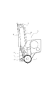
まず、図1を参照して補給方式のカラー電子写真画像形成装置の全体構成について説明する。なお、図1は、補給方式のカラー電子写真画像形成装置(フルカラーレーザービームプリンタ)100の全体構成を示す縦断面図である。
[Overall configuration of color electrophotographic image forming apparatus]
First, an overall configuration of a replenishment type color electrophotographic image forming apparatus will be described with reference to FIG. FIG. 1 is a longitudinal sectional view showing the overall configuration of a replenishment type color electrophotographic image forming apparatus (full color laser beam printer) 100.
同図に示す画像形成装置100は、水平方向に並設された4個の感光体ドラム1a,1b,1c,1dを有している。感光体ドラム1は、駆動手段(不図示)によって回転駆動される。感光体ドラム1の周囲には、帯電ローラ2(2a、2b、2c、2d)、スキャナユニット3(3a、3b、3c、3d)、現像ユニット4(4a、4b、4c、4d)、中間転写ベルト5、クリーニングブレード7(7a、7b、7c、7d)が設けられている。ここで、前記帯電ローラ2(2a、2b、2c、2d)は、感光体ドラム1の周面を均一に帯電する。また、前記スキャナユニット3(3a、3b、3c、3d)は、画像情報に基づいて感光体ドラム1にレーザー光Lを照射して、感光体ドラム1に静電潜像を形成する。また、前記現像ユニット4(4a、4b、4c、4d)は、前記静電潜像に現像剤を付着させて現像剤像として現像する。前記現像ユニット4は、前記感光体ドラム1の短手方向において、前記感光体ドラム1の一端側に配置されている。更に、前記中間転写ベルト5は、前記感光体ドラム1に形成された現像剤像を転写される。また、前記クリーニングブレード7(7a、7b、7c、7d)は、転写後の感光体ドラム1周面に残った転写残現像剤を除去する。更に、2次転写ローラ6は、中間転写ベルト5に転写された現像剤像を記録媒体Sに転写させる。
The
ここで、感光体ドラム1、帯電ローラ2、現像ユニット4、及び、クリーニングブレード7は一体化されてプロセスカートリッジ8(8a、8b、8c、8d)を構成している。また、プロセスカートリッジ8の上方には、プロセスカートリッジ8に現像剤を補給するための現像剤カートリッジ9(9a、9b、9c、9d)が取り外し可能に配置されている(プロセスカートリッジ8の枠体構成については後で説明する)。ここで、プロセスカートリッジ8は、被位置決め部81〜83によって装置本体99に設けられた位置決め部(不図示)に位置決めされる(図2参照)。そして、現像剤カートリッジ9は、位置決め部92、93によって装置本体99にも受けられた位置決め部(不図示)に位置決めされる(図2参照)。
Here, the
以下、感光体ドラム1から順に画像形成の動作について説明する。
Hereinafter, the image forming operation will be described in order from the
まず、感光体ドラム1a、1b、1c、1dが、画像形成タイミングに合わせて順次に回転駆動される。そして、各々のプロセスカートリッジ8に対応するスキャナユニット3が順次駆動される。また、感光体ドラム1が回転することで、感光体ドラム1に接触している帯電ローラ2も従動回転する。そして、帯電ローラ2にバイアスが印加されることによって、感光体ドラム1の周面に一様な電荷が付与される。そして、スキャナユニット3は、その感光体ドラム1周面に画像情報に応じて選択的に露光を行う。これによって、感光体ドラム1周面に静電潜像が形成される。現像ユニット4に設けられた現像ローラ17は、前記静電潜像に現像剤を転移させて感光体ドラム1周面に現像剤像を形成する。即ち、現像ローラ17は、感光体ドラム1に形成された静電潜像を現像する。そして、前記現像剤像は、感光体ドラム1から中間転写ベルト5に一括転写される。その後、前記現像剤像は、中間転写ベルト5によって、2次転写ロ−ラ6の位置まで搬送される。
First, the
一方、中間転写ベルト6周面における現像剤像の先端と、記録媒体Sの画像形成開始位置とが一致するように、レジストローラ対10が回転して記録媒体Sを搬送する。このように搬送された記録媒体Sは、2次転写ローラ6によって、前記中間転写ベルト6周面の前記現像剤像を転写される。
On the other hand, the
現像剤像を転写された記録媒体Sは、定着部11に搬送される。記録媒体Sは、定着部11で上記現像剤像を熱定着される。その後、排出ローラ対12によって、排出部13から画像面を下にした状態で本体外に排出される。
The recording medium S to which the developer image is transferred is conveyed to the fixing
[プロセスカートリッジの枠体構成の説明]
次に、図2を用いて、プロセスカートリッジ8の構成を説明する。
[Description of frame structure of process cartridge]
Next, the configuration of the process cartridge 8 will be described with reference to FIG.
図2に示すように、カートリッジ8は、クリーニングユニットとしてのドラムユニット14と現像ユニット4とが一体となった構成を有している。ここで、前記現像ユニット4は、前記ドラムユニット14に移動可能に取り付けられている。
As shown in FIG. 2, the cartridge 8 has a configuration in which a
ドラムユニット14は、感光体ドラム1を回転可能に支持する枠体であるクリーニング容器15を有している。ここで、前記クリーニング容器15は、前記感光体ドラム1の軸線(長手)方向の全域に沿って設けられている。また、前記クリーニング容器15は、前記帯電ローラ2及び前記ブレード7を支持している。また、前記クリーニング容器15は、前記ブレード7によって前記感光体ドラム1から除去された現像剤を収納する第一除去現像剤収納部40を有している。
The
一方、現像ユニット4は、現像剤を収納する第二現像剤収納部としての現像剤収納容器16と現像容器18とが超音波溶着等で結合されている。ここで、前記現像剤収納容器16は、現像剤カートリッジ9から補給された現像剤を収納するためのものである。そして、前記現像剤は、前記静電潜像の現像に用いられる。ここで、前記現像剤収納容器16は、プロセスカートリッジ8の外部から現像剤を受け入れるための現像剤受け入れ口45を有する。即ち、前記受け入れ口45は、現像剤カートリッジ9内に収納されている現像剤を受け入れるためのものである。前記受け入れ口45は、前記現像剤収納容器16の上方に設けられている。そして、通常は、現像剤が外部に飛散しないように、前記受け入れ口45はシャッター(不図示)によって覆われている。一方、第一現像剤収納部としての現像剤カートリッジ9に設けられた現像剤供給口91は、前記受け入れ口45から前記プロセスカートリッジ8内へ現像剤を受け入れるためのものである。また、通常は、現像剤が外部に飛散しないように、前記供給口91もシャッター(不図示)によって覆われている。そして、プロセスカートリッジ8及び現像剤カートリッジ9が装置本体99に装着された際に、各シャッター(不図示)が前記受け入れ口45及び前記供給口から退避して、前記受け入れ口45と前記供給口とが対向する。これにより、現像剤がプロセスカートリッジ8内へ受け入れられる。また、前記受け入れ口45は、前記プロセスカートリッジ8が装置本体99に装着された際に、上方を向くように構成されている。また、前記供給口91は、前記現像剤カートリッジ9が装置本体99に装着された際に、下を向くように構成されている。そこで、現像剤カートリッジ9が装置本体99に装着された際に、装置本体99に装着されているプロセスカートリッジ8に、前記供給口91及び前記受け入れ口を介して現像剤が補給される。前記現像容器18は、現像剤収納容器16内の現像剤を用いて前記静電潜像を現像するための現像ローラ17を回転可能に支持する。
On the other hand, in the developing unit 4, a
前記現像容器18には、現像ローラ17の他に、現像ブレード19及び現像剤供給ローラ20等が設けられている。ここで、前記現像ブレード19は、現像ローラ17周面に付着した現像剤の層厚を規制する。また、前記現像剤供給ローラ20は、現像ローラ17周面に現像剤を供給するためのスポンジローラである。
In addition to the developing
尚、現像ユニット4は、結合部21を中心に、感光体ドラムユニット14に対して揺動可能に支持されている。さらに、前記現像ユニット4は、バネ等の弾性部材22によって前記感光体ドラムユニット14に付勢されている。これにより、現像ローラ17は、感光体ドラム1に当接されている。
The developing unit 4 is supported so as to be swingable with respect to the
[プロセスカートリッジにおける除去現像剤の回収構成]
次にプロセスカートリッジ8内において、感光体ドラム1から除去された現像剤の回収構成について、図3〜5を用いて説明する。
[Recovery configuration of removed developer in process cartridge]
Next, a configuration for collecting the developer removed from the
感光体ドラム1に形成された現像剤像は、中間転写ベルト5に一括転写される。この際、感光体ドラム1に形成された現像剤像が全て中間転写体5に転写されるわけではなく、転写されずに感光体ドラム1に現像剤が残存する。
The developer image formed on the
そして、感光体ドラム1に残留した現像剤は、前記クリーニングブレード7によって除去される。図3に示すように、ブレード7は、ゴムなどの弾性体を用いたブレード部材である。そして、ブレード7のエッジ部7aはその長手方向全域に渡って感光体ドラム1の表面に当接されている。これにより、感光体ドラム1に付着した現像剤Hが掻き取られる。
The developer remaining on the
そして、ブレード7によって除去された現像剤は、一旦、第一除去現像剤収納部40に収納される。ここで、第一除去現像剤収納部40は、前記感光体ドラム1の軸線方向からみて、前記感光体ドラム1の短手方向の他端側に位置している。そして、第一除去現像剤収納部40に収納された除去現像剤Hは、第二除去現像剤収納部23に搬送される。ここで、図4、図5に示すように、第二除去現像剤収納部23は、プロセスカートリッジ8の長手全域に亘って設けられている。また、第二除去現像剤収納部23は、クリーニング容器15と別体のフタ部材24が超音波溶着等で結合されることで構成されている。
The developer removed by the
[第二除去現像剤収納部の配置]
また、図6に示すように、カートリッジ8が装置本体99に装着された状態において、第二除去現像剤収納部23は、第一除去現像剤収納部40の上方に配置されている。また、第二除去現像剤収納部23は、鉛直方向において、前記現像剤受け入れ口45よりも上方に突出して設けられている(図2参照)。言い換えれば、第二除去現像剤収納部23は、現像ユニット4の上方に配置されている隣の現像剤カートリッジ9に挟まれる位置(図中Aの位置)に設けられている。このように、補給方式の画像形成装置100において第二除去現像剤収納部23を前述した位置に設けることにより、プロセスカートリッジ8、および電子写真画像形成装置の小型化に寄与することができる。特に、装置の水平方向の大きさを小さくすることができる。即ち、プロセスカートリッジ8の底面積を小さくすることができる。
[Arrangement of second removed developer storage section]
As shown in FIG. 6, the second removed
ここで、本実施例においては、図6の領域A、即ち、第一除去現像剤収納部40の上方に第二除去現像剤収納部23を配置している。ここで、プロセスカートリッジ8と現像剤カートリッジ9を装置本体99に装着した際の鉛直方向において、第二除去現像剤収納部23は現像ユニット4よりも上方に突出して設けられている。更に言い換えると、プロセスカートリッジ8と現像剤カートリッジ9を装置本体99に装着した際の水平方向において、第二除去現像剤収納部23は、現像剤カートリッジ9とオーバーラップしている。また、前記鉛直方向からみた際に、現像剤カートリッジ9と現像ユニット4もオーバーラップしている。ここで、現像剤カートリッジ9と第二除去現像剤収納部23との間をレーザー光Lが通過するように、現像剤カートリッジ9とプロセスカートリッジ8はそれぞれ配置されている。これによって、プロセスカートリッジ8と現像剤カートリッジ9を、装置本体99内に効率良く配置することができる。ひいては、装置の小型化を達成することができる。
Here, in this embodiment, the second removed
[除去現像剤搬送構成]
次にプロセスカートリッジの除去現像剤の搬送構成について説明する。
[Removed developer transport configuration]
Next, the removal developer transport structure of the process cartridge will be described.
図8に示すように、第一のスクリュー部材25が、ブレード7の感光体ドラム1に当接する当接面の反対側に長手全域に渡って配置されている。そして、ブレード7によって掻き取られた現像剤は、前記第一のスクリュー部材25によって、プロセスカートリッジ8の長手方向の一端(図中矢印F方向)に搬送される。
As shown in FIG. 8, the
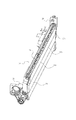
図9に示すように、現像剤搬送部材としての除去現像剤垂直上方搬送ユニット26が、プロセスカートリッジ8の長手方向の一端に設けられている。ここで、第一のスクリュー部材25によって搬送された現像剤は、前記搬送ユニット26によって、第二除去現像剤収納部23に搬送される。尚、第一のスクリュー部材25と前記搬送ユニット26は、接続している。前記搬送ユニット26は、無端の両歯付きタイミングベルト27を有する。ベルト27は、芯線が入ったゴム部材か、もしくは、芯線無しの樹脂部材である。なお、芯線無しの樹脂製タイミングベルトを使用する場合、その材質は、ポリエステル系エラストマーであることが望ましい。
As shown in FIG. 9, a removed developer vertical
ベルト27の内歯27aは、回転可能な上側のプーリ部材28a及び下側のプーリ部材28bと噛み合っている。そして、ベルト27は、これら2つのプーリ部材28a、28bによって両端を固定された状態になっている。2つのプーリ部材28a、28bのどちらか一方が回転することで、ベルト27も回転する。また、上側のプーリ部材28aと下側のプーリ部材28bとの軸間距離に対して、ベルト27の周長は、若干短くなっている。そして、上側のプーリ部材28aと下側のプーリ部材28bにベルト27を取り付けたとき、ベルト27に所定の張力がかかるようになっている。
The
ここで、ベルト27にかける張力が高すぎると、ベルト27の回転トルクが高くなってしまう。反対に、張力が低すぎると、プーリ部材28a、28bとタイミングベルト27の歯飛びが発生してしまう。そのため、前述したようなベルト27を用いたとき、フリー状態のベルト27に対して、上側のプーリ部材28aと下側のプーリ部材28bに取り付けたときの伸張率が約1.5〜2.0%になるように張力を設定することが望ましい。
Here, if the tension applied to the
図10に示すように、第一のスクリュー部材25によって搬送された除去現像剤Hは、ベルト27の外歯27bに入り込む。そして、ベルト27が矢印G方向に回転することで、外歯27bに入り込んだ除去現像剤Hは、上方に搬送される。
As shown in FIG. 10, the removed developer H conveyed by the
図11に示すように、ベルト27によって上方へ搬送された除去現像剤Hは、前記搬送ユニット26の上側に接続している第二のスクリュー部材29の位置まで運ばれる。第二のスクリュー部材29は、第二除去現像剤収納部23の長手方向の全域に渡って設けられている。
As shown in FIG. 11, the removed developer H transported upward by the
尚、図12に示すように、ベルト27と第二のスクリュー部材29の位置関係は以下のような配置になっている。即ち、前記長手方向から見て、第二のスクリュー部材29の上方では、ベルト27が鉛直方向と角度θを持った状態で配置されている。このような配置にする理由は、効率よくベルト27上に除去現像剤Hを第二のスクリュー部材29に送るためである。仮に、第二のスクリュー部材29の上方において、ベルト27を垂直に配置すると、ベルト27の外歯27bに入り込んだ除去現像剤Hが第二のスクリュー部材29に落下しにくい。そこで、第二のスクリュー部材29の上方で、ベルト27が角度θを持った状態で配置している。そして、その角度θを利用してベルト27上の除去現像剤Hを第二のスクリュー部材29に落下させている。ここで、角度θは、10°以上に設定することが望ましい。
As shown in FIG. 12, the positional relationship between the
その後、図13に示すように、現像剤は、第二のスクリュー部材29によって、現像剤搬送方向(図中矢印J方向)の上流側から第二除去現像剤収納部23に収納されていく。第二除去現像剤収納部23の内部は、仕切り壁30a〜cによって、複数のスペース31a〜dに仕切られている。
Thereafter, as shown in FIG. 13, the developer is stored in the second removed
また、図14に示すように、複数のスペース31a〜dのそれぞれ中央部において、第二のスクリュー部材29は、現像剤搬送方向(図中矢印J方向)とは、逆方向のスクリュー(以下、逆スクリュー部32a〜d)が1〜2巻き設けられている。このような構成とすることで、第二のスクリュー部材29によって搬送された現像剤が逆スクリュー部2a〜dによって矢印J´方向に押し戻される。
Further, as shown in FIG. 14, the
そのため、図15に示すように、現像剤搬送方向と直交する方向(図中矢印K方向)に現像剤が広がっていく。これにより、第二除去現像剤収納部23に貯蔵される現像剤のかさ密度を高めることができる。そして、その結果、限られたスペースにより多くの現像剤を貯蔵することが可能となる。
Therefore, as shown in FIG. 15, the developer spreads in a direction (arrow K direction in the figure) perpendicular to the developer transport direction. Thereby, the bulk density of the developer stored in the second removed
[現像剤搬送手段の駆動構成]
次に現像剤搬送手段の駆動構成について説明する。
[Drive configuration of developer conveying means]
Next, the driving configuration of the developer conveying means will be described.
図16に示すように、第二のスクリュー部材29は、除去現像剤収納部23の長手方向の全域に渡って設けられている。第二のスクリュー部材29の一端は、前記搬送ユニット26と接続している。そして、第二のスクリュー部材29の他端は、装置本体99からの駆動入力を受けるための端面カップリング部材33が設けられている。
As shown in FIG. 16, the
また、第二のスクリュー部材29の前記搬送ユニット26と接続している側には、第一のアイドラギア34が設けられている。さらに、図17に示すように、第一のアイドラギア34は、前記搬送ユニット26のベルト27と噛み合っている上側のプーリ部材28aと同軸上で結合している第二のアイドラギア35と噛み合っている。一方、下側のプーリ部材28bは、同軸上で第一のスクリュー部材25と結合している。
A
以上の構成により、装置本体99から駆動入力を受けた第二のスクリュー部材29の駆動は、第一のアイドラギア34、第二のアイドラギア35を介して、上側のプーリ部材28aに伝達される。上側のプーリ部材28aが回転することでベルト27も回転し、さらに、下側のプーリ部材28bも回転する。そして、下側のプーリ部材28bが回転することで、第一のスクリュー部材25が回転する。このような構成とすることで、複数の搬送方向の異なる現像剤搬送手段が設けられているプロセスカートリッジ8においても、ひとつの駆動入力で効率的に現像剤の搬送を行うことが可能となる。プロセスカートリッジ8に除去現像剤収納部を設け、除去現像剤収納部をプロセスカートリッジ周辺の空きスペースに効率よく配置し、さらに、第二除去現像剤収納部23に現像剤を搬送する前記搬送ユニット26を設けている。そのため、補給方式で、且つ、異なる色の現像剤を収容したプロセスカートリッジを複数個用いて、これらを水平に配置し、さらに中間転写体を用いたフルカラー画像形成装置の小型化、および省スペース化を図ることができた。そして、ユーザにとって使い勝手のよいプロセスカートリッジ構成を実現するための除去現像剤収納構成を備えたプロセスカートリッジを提供が可能となる。
With the above configuration, the driving of the
(実施例2)
次に、本発明にかかる第二の実施例について説明する。基本的な構成は実施例1と同様であり、画像形成方向(図中矢印B方向)における下流側のプロセスカートリッジの第二除去現像剤収納部23の構成だけが異なる。
(Example 2)
Next, a second embodiment according to the present invention will be described. The basic configuration is the same as that of the first embodiment, and only the configuration of the second removed
最初に、実施例1の図7を用いて、中間転写ベルト上のかぶり現像剤と除去現像剤回収部の容量について説明する。 First, the capacities of the fog developer and the removed developer collection unit on the intermediate transfer belt will be described with reference to FIG.
図7に示すように、画像形成方向(図中矢印B方向)に対して略水平に複数並べられたプロセスカートリッジ8の感光体ドラム1の表面には、中間転写ベルト5が当接している。中間転写ベルト5は、矢印B方向に回転する。感光体ドラム1に形成された現像剤像は、画像形成方向上流から順次中間転写ベルト5に転写されていく。このとき、複数の感光体ドラム1は、それぞれ印加されるバイアスが異なる。そのため、上流側で中間転写ベルト5に転写された現像剤像が、下流側の感光体ドラム1に乗らないように制御を行っている。しかし、微量の現像剤(かぶり現像剤)は、感光体ドラム1に印加されたバイアスの影響を受けにくいため感光体ドラム1の表面に乗ることがある。
As shown in FIG. 7, the intermediate transfer belt 5 is in contact with the surface of the
そこで、プロセスカートリッジ8の第二除去現像剤収納部23の容量を、画像形成方向の下流に行くにしたがって大きくした。このため、下流側のプロセスカートリッジ8は、プロセスカートリッジ8内で除去された現像剤以外にも、上流側のプロセスカートリッジ8から発生するかぶり現像剤をも第二除去現像剤収納部23に回収できる。従って、下流側のプロセスカートリッジ8の方が上流側のプロセスカートリッジ8よりも早く第二除去現像剤収納部23が満たされてしまうことを防止できる。
Therefore, the capacity of the second removed
即ち、図18に示すように、本実施例においては、かぶり現像剤対策として画像形成方向最下流に装着されるプロセスカートリッジ8dの第二除去現像剤収納部23dの容量を大きくした。これにより、画像形成装置100を大型化することなく、かぶり現像剤の問題を解決できた。
That is, as shown in FIG. 18, in this embodiment, the capacity of the second removed
また、先述したように、第二除去現像剤収納部23は、クリーニング容器15とフタ部材24とが結合することで形成されている。ここで、かぶり現像剤対策として、画像形成方向最下流のプロセスカートリッジ8の第二除去現像剤収納部23の容量を大きくする際に、クリーニング容器15は、他のプロセスカートリッジ8と同じものを使用して、フタ部材24dの形状を変えることで容量アップに対応した。こうすることで、最小限の部品形状変更で第二除去現像剤収納部23の容量アップを行うことができた。
Further, as described above, the second removed
1 感光体ドラム
4 現像ユニット
5 中間転写ベルト
8 プロセスカートリッジ
9 現像剤カートリッジ
11 定着ユニット
12 排紙ユニット
14 感光体ドラムユニット
15 クリーニング容器
16 現像剤収納容器
17 現像ローラ
21 結合部(支点)
22 弾性部材
23 第二除去現像剤収納部
24 フタ部材
25 第一のスクリュー部材
26 除去現像剤垂直上方搬送ユニット
27 タイミングベルト
27a 内歯
27b 外歯
28a 上側のプーリ部材
28b 下側のプーリ部材
29 第二のスクリュー部材
30 仕切り壁
31a〜d スペース
32a〜d 逆スクリュー部
33 端面カップリング部材
34 第一のアイドラギア
35 第二のアイドラギア
40 第一除去現像剤収納部
45 現像剤受け入れ口
S 記録媒体
H 除去現像剤
L レーザ光
θ タイミングベルトの配置角度
A 除去現像剤収納部の領域
B 画像形成方向
C 現像剤カートリッジの出っ張り部
E ユニット間の隙間
F 第一のスクリュー部材の搬送方向
G タイミングベルトの回転方向
J 第一のスクリュー部材の搬送方向
K 除去現像剤が広がる方向
DESCRIPTION OF
22
Claims (9)
前記像担持体から現像剤を除去するためのクリーニング部材と、
前記像担持体から除去された現像剤を収納する第一除去現像剤収納部と、
前記第一除去現像剤収納部の上方に設けられ前記第一除去現像剤収納部から搬送される現像剤を収納する第二除去現像剤収納部と、
前記第一除去現像剤収納部に収納された現像剤を前記第二除去現像剤収納部へ搬送するための搬送手段と、
を有し、
前記搬送手段は、現像剤を搬送可能なベルトを備えており、
前記ベルトは、前記第二除去現像剤収納部の長手方向から見た時に、第一の傾き部と、前記第一の傾きと異なる第二の傾き部とを持っており、
前記ベルトは、前記第一の傾き部で前記第一除去現像剤収納部に収納された現像剤を保持可能となっており、前記ベルトに保持された前記現像剤は、前記ベルトの鉛直方向の頂上点に達する前の前記第二の傾き部で、前記第二除去現像剤収納部に収納可能な位置に落下させられることを特徴とするクリーニングユニット。 A cleaning unit provided in an image forming apparatus for forming a developer image on an image carrier,
A cleaning member for removing the developer from the image carrier;
A first removed developer storage section for storing the developer removed from the image carrier;
A second removed developer storage section that is provided above the first removed developer storage section and stores the developer conveyed from the first removed developer storage section;
Conveying means for conveying the developer stored in the first removed developer storage section to the second removed developer storage section;
Have
The transport means includes a belt capable of transporting the developer,
The belt has a first inclined portion and a second inclined portion different from the first inclination when viewed from the longitudinal direction of the second removed developer storage portion ,
The belt can hold the developer stored in the first removed developer storage portion at the first inclined portion, and the developer held on the belt can move in the vertical direction of the belt. The cleaning unit, wherein the cleaning unit is dropped to a position that can be accommodated in the second removed developer accommodating portion at the second inclined portion before reaching the top point .
前記搬送手段により搬送された現像剤を前記第二除去現像剤収納部の長手方向に搬送するためのスクリュー部材と、を備え、前記ベルトに保持された現像剤は、前記第二の傾き部で前記スクリュー部材の上に落下することを特徴とする請求項1又は2に記載のクリーニングユニット。 The conveying means is provided in a part of the longitudinal direction of the first removed developer accommodating portion and the second removed developer accommodating portion,
A screw member for conveying the developer conveyed by the conveying means in the longitudinal direction of the second removed developer accommodating portion, and the developer held by the belt is at the second inclined portion. The cleaning unit according to claim 1, wherein the cleaning unit falls onto the screw member.
前記像担持体を備える前記クリーニングユニットと、を有し、
前記プロセスカートリッジ及び前記現像剤カートリッジが前記画像形成装置本体に装着された状態で、前記現像ユニットが前記現像剤カートリッジの下であって前記クリーニングユニットの横に位置し、前記第二除去現像剤収納部が前記第一除去現像剤収納部の上であって前記現像剤カートリッジの横に位置し、前記クリーニングユニットが請求項1乃至3のいずれかに記載のクリーニングユニットであることを特徴とするプロセスカートリッジ。 An image in which a developer cartridge having a first developer storage section for storing the developer and a developer supply port for supplying the developer stored in the first developer storage section is detachably mounted. A process cartridge that is detachably attached to the main body of the forming apparatus, wherein the process cartridge includes a developer receiving port for receiving the developer supplied from the developer supply port, and a development received from the developer receiving port. Development having a second developer accommodating portion for accommodating the developer, and a developing roller for developing the electrostatic latent image formed on the image carrier using the developer accommodated in the second developer accommodating portion. Unit,
The cleaning unit comprising the image carrier,
With the process cartridge and the developer cartridge mounted on the image forming apparatus main body, the developing unit is located below the developer cartridge and next to the cleaning unit, and stores the second removed developer. 4. The process according to claim 1, wherein the cleaning unit is a cleaning unit according to claim 1, wherein the cleaning unit is located above the first removed developer storage unit and beside the developer cartridge. 5. cartridge.
前記像担持体を備えるクリーニングユニットと、前記像担持体に形成された静電潜像を現像する現像ローラと、を有する現像ユニットと、を備え、前記クリーニングユニットは請求項1乃至3のいずれかに記載のクリーニングユニットであることを特徴とする画像形成装置。 In an image forming apparatus for forming a developer image on an image carrier,
A cleaning unit including the image carrier and a developing unit that develops an electrostatic latent image formed on the image carrier, and the cleaning unit is any one of claims 1 to 3. An image forming apparatus comprising the cleaning unit according to claim 1.
i)現像剤を収納する第一現像剤収納部と、前記第一現像剤収納部に収納された現像剤を供給するための現像剤供給口と、を有し、前記画像形成装置の装置本体に取り外し可能に装着された現像剤カートリッジと、
ii)前記現像剤供給口から供給された現像剤を受け入れるための現像剤受け入れ口と、前記現像剤受け入れ口から受け入れられた現像剤を収納する第二現像剤収納部と、前記第二現像剤収納部に収納された現像剤を用いて、像担持体に形成された静電潜像を現像する現像ローラと、を有する現像ユニットと、
前記像担持体を備えるクリーニングユニットと、
を有し、前記装置本体に取り外し可能に装着されたプロセスカートリッジと、
を有し、
iii)前記プロセスカートリッジ及び前記現像剤カートリッジが前記装置本体に装着された状態で、前記現像ユニットが前記クリーニングユニットの横に位置し、前記第二除去現像剤収納部が前記第一除去現像剤収納部の上に位置し、前記現像剤カートリッジが前記現像ユニットの上であって前記第二除去現像剤収納部の横に位置し、前記クリーニングユニットが請求項1乃至3のいずれかに記載のクリーニングユニットであることを特徴とする画像形成装置。 In an image forming apparatus for forming a developer image on an image carrier,
i) an apparatus main body of the image forming apparatus, comprising: a first developer accommodating portion for accommodating a developer; and a developer supply port for supplying the developer accommodated in the first developer accommodating portion. A developer cartridge detachably mounted on the
ii) a developer receiving port for receiving the developer supplied from the developer supply port, a second developer storage unit for storing the developer received from the developer receiving port, and the second developer A developing unit having a developing roller that develops the electrostatic latent image formed on the image carrier using the developer stored in the storage unit;
A cleaning unit comprising the image carrier;
And a process cartridge detachably mounted on the apparatus main body,
Have
iii) In a state where the process cartridge and the developer cartridge are mounted on the apparatus main body, the developing unit is positioned beside the cleaning unit, and the second removed developer storage portion stores the first removed developer storage. The cleaning unit according to any one of claims 1 to 3, wherein the cleaning unit is positioned on the developing unit, the developer cartridge is positioned on the developing unit and beside the second removed developer storage unit. An image forming apparatus which is a unit.
前記現像剤供給口は、前記現像剤カートリッジが前記装置本体に装着された際に前記現像剤カートリッジの下に位置していることを特徴とする請求項8に記載の画像形成装置。 The developer receiving port is located on the developing unit when the process cartridge is mounted on the apparatus main body,
The image forming apparatus according to claim 8, wherein the developer supply port is positioned below the developer cartridge when the developer cartridge is attached to the apparatus main body.
Priority Applications (2)
| Application Number | Priority Date | Filing Date | Title |
|---|---|---|---|
| JP2005073115A JP4817682B2 (en) | 2004-12-13 | 2005-03-15 | Cleaning unit, process cartridge, and image forming apparatus |
| US11/094,371 US7366440B2 (en) | 2004-12-13 | 2005-03-31 | Process cartridge feeding developer from first to second removed developer accommodating portions and image forming apparatus to which the cartridge is mountable |
Applications Claiming Priority (3)
| Application Number | Priority Date | Filing Date | Title |
|---|---|---|---|
| JP2004360033 | 2004-12-13 | ||
| JP2004360033 | 2004-12-13 | ||
| JP2005073115A JP4817682B2 (en) | 2004-12-13 | 2005-03-15 | Cleaning unit, process cartridge, and image forming apparatus |
Publications (3)
| Publication Number | Publication Date |
|---|---|
| JP2006195401A JP2006195401A (en) | 2006-07-27 |
| JP2006195401A5 JP2006195401A5 (en) | 2008-05-01 |
| JP4817682B2 true JP4817682B2 (en) | 2011-11-16 |
Family
ID=36584047
Family Applications (1)
| Application Number | Title | Priority Date | Filing Date |
|---|---|---|---|
| JP2005073115A Expired - Fee Related JP4817682B2 (en) | 2004-12-13 | 2005-03-15 | Cleaning unit, process cartridge, and image forming apparatus |
Country Status (2)
| Country | Link |
|---|---|
| US (1) | US7366440B2 (en) |
| JP (1) | JP4817682B2 (en) |
Families Citing this family (20)
| Publication number | Priority date | Publication date | Assignee | Title |
|---|---|---|---|---|
| JP4865341B2 (en) * | 2005-02-04 | 2012-02-01 | キヤノン株式会社 | Process cartridge and electrophotographic image forming apparatus |
| US8275285B2 (en) | 2007-02-26 | 2012-09-25 | Ricoh Company, Ltd. | Process cartridge and image forming apparatus |
| JP5359211B2 (en) * | 2007-12-17 | 2013-12-04 | 株式会社リコー | Waste toner collecting device, process cartridge, and image forming apparatus |
| JP4968957B2 (en) * | 2008-03-31 | 2012-07-04 | キヤノン株式会社 | Frame body unit, developing device and process cartridge, and frame body unit, developing device and process cartridge manufacturing method |
| JP5127565B2 (en) * | 2008-05-23 | 2013-01-23 | キヤノン株式会社 | Cartridge and image forming apparatus |
| JP5004870B2 (en) * | 2008-05-23 | 2012-08-22 | キヤノン株式会社 | Process cartridge and electrophotographic image forming apparatus |
| JP5267012B2 (en) * | 2008-09-29 | 2013-08-21 | 株式会社リコー | Waste toner collecting container, cleaning unit, and image forming apparatus |
| JP5402741B2 (en) * | 2010-03-16 | 2014-01-29 | コニカミノルタ株式会社 | Image forming apparatus |
| JP5257417B2 (en) * | 2010-07-23 | 2013-08-07 | ブラザー工業株式会社 | Image forming apparatus |
| US8873999B2 (en) | 2011-12-26 | 2014-10-28 | Brother Kogyo Kabushiki Kaisha | Image forming apparatus having waste developer accommodating portion |
| JP5936370B2 (en) * | 2012-01-25 | 2016-06-22 | キヤノン株式会社 | Cleaning device, process cartridge, image forming apparatus |
| US9182733B2 (en) | 2013-02-07 | 2015-11-10 | Canon Kabushiki Kaisha | Developer supply cartridge, process cartridge and image forming apparatus |
| CA3071424A1 (en) | 2015-02-27 | 2016-09-01 | Canon Kabushiki Kaisha | Cartridge |
| JP6667249B2 (en) * | 2015-10-14 | 2020-03-18 | キヤノン株式会社 | cartridge |
| JP6921636B2 (en) | 2016-06-14 | 2021-08-18 | キヤノン株式会社 | Process cartridge and electrophotographic image forming apparatus |
| JP6787031B2 (en) * | 2016-10-18 | 2020-11-18 | ブラザー工業株式会社 | Image forming equipment and process cartridge |
| JP7058992B2 (en) | 2017-12-13 | 2022-04-25 | キヤノン株式会社 | Image forming equipment and cartridge |
| CN116414014A (en) | 2017-12-13 | 2023-07-11 | 佳能株式会社 | Cartridge and image forming apparatus |
| US10627780B2 (en) | 2018-01-23 | 2020-04-21 | Canon Kabushiki Kaisha | Cartridge and image forming apparatus |
| JP7358087B2 (en) * | 2019-06-28 | 2023-10-10 | キヤノン株式会社 | Image forming device |
Family Cites Families (14)
| Publication number | Priority date | Publication date | Assignee | Title |
|---|---|---|---|---|
| US4768055A (en) * | 1986-06-17 | 1988-08-30 | Mita Industrial Co., Ltd. | Image forming machine having a toner recycling unit |
| JPH05107918A (en) | 1991-10-16 | 1993-04-30 | Ricoh Co Ltd | Toner cartridge |
| JPH05107992A (en) * | 1991-10-19 | 1993-04-30 | Canon Inc | Cleaning device for image forming device |
| JPH0815935A (en) | 1994-06-30 | 1996-01-19 | Fujitsu Ltd | Multicolor image forming device |
| JP3281595B2 (en) * | 1997-06-19 | 2002-05-13 | 株式会社沖データ | Electrophotographic recording device |
| JPH11305623A (en) * | 1998-04-21 | 1999-11-05 | Ricoh Co Ltd | Image forming device |
| JP2000010376A (en) * | 1998-06-26 | 2000-01-14 | Fujitsu Ltd | Image forming device |
| JP3919383B2 (en) * | 1999-05-24 | 2007-05-23 | キヤノン株式会社 | Electrophotographic image forming apparatus |
| JP2001083863A (en) | 1999-09-17 | 2001-03-30 | Ricoh Co Ltd | Process cartridge |
| JP3679665B2 (en) * | 1999-11-19 | 2005-08-03 | キヤノン株式会社 | Gap assurance member, developing device, charging device, and process cartridge |
| JP3715879B2 (en) * | 2000-10-12 | 2005-11-16 | キヤノン株式会社 | Process cartridge and electrophotographic image forming apparatus |
| JP3566697B2 (en) * | 2001-02-09 | 2004-09-15 | キヤノン株式会社 | Process cartridge, electrophotographic image forming apparatus, and separation mechanism |
| JP2004021134A (en) * | 2002-06-20 | 2004-01-22 | Canon Inc | Image forming apparatus |
| JP2004101592A (en) | 2002-09-05 | 2004-04-02 | Oki Data Corp | Image forming apparatus |
-
2005
- 2005-03-15 JP JP2005073115A patent/JP4817682B2/en not_active Expired - Fee Related
- 2005-03-31 US US11/094,371 patent/US7366440B2/en active Active
Also Published As
| Publication number | Publication date |
|---|---|
| US20060127128A1 (en) | 2006-06-15 |
| US7366440B2 (en) | 2008-04-29 |
| JP2006195401A (en) | 2006-07-27 |
Similar Documents
| Publication | Publication Date | Title |
|---|---|---|
| JP4817682B2 (en) | Cleaning unit, process cartridge, and image forming apparatus | |
| US6937838B2 (en) | Waste toner collecting device, and image forming apparatus including the waste toner collecting device | |
| US7398038B2 (en) | Image forming apparatus using a toner container and a process cartridge | |
| JP4610468B2 (en) | Toner recovery device, image forming unit, and image forming apparatus | |
| US8260186B2 (en) | Toner cartridge with refillable fresh and residual toner chambers, process cartridge, and method of making toner cartridge reusable | |
| JP3537293B2 (en) | Electrophotographic apparatus and photoreceptor unit | |
| JP2008116907A (en) | Waste-toner housing device, and image forming apparatus | |
| JP2008033090A (en) | Powder conveying device, developing device, process cartridge and image forming apparatus | |
| JP3305948B2 (en) | Image forming device | |
| JP2011257692A (en) | Toner conveying device, and toner cartridge and cleaning unit having the same | |
| JP3705364B2 (en) | Image forming apparatus, process cartridge and developing device used therefor | |
| JP3931961B2 (en) | Image forming apparatus, process cartridge and developing device used therefor | |
| JP4682507B2 (en) | Image forming apparatus | |
| JP2008065229A (en) | Toner storing component and image forming apparatus | |
| US7689147B2 (en) | Developing apparatus and developer collecting method | |
| JP4880948B2 (en) | Developer transport device, process cartridge, and image forming apparatus | |
| JPH0844179A (en) | Toner cartridge and image forming device provided with the same | |
| JP2004198768A (en) | Waste powder recovery device and image forming apparatus | |
| JP2015180976A (en) | Toner conveyance unit and image forming apparatus | |
| JP4400250B2 (en) | Image forming apparatus | |
| JP4881487B2 (en) | Developer transport device, process cartridge, and image forming apparatus | |
| JP4256990B2 (en) | Image forming apparatus | |
| JP3016963B2 (en) | Replacement method of toner collection container in electrophotographic apparatus | |
| JP6159855B2 (en) | Image forming apparatus | |
| JP4804174B2 (en) | Developing device, process cartridge, and electrophotographic image forming apparatus |
Legal Events
| Date | Code | Title | Description |
|---|---|---|---|
| A521 | Request for written amendment filed |
Free format text: JAPANESE INTERMEDIATE CODE: A523 Effective date: 20080317 |
|
| A621 | Written request for application examination |
Free format text: JAPANESE INTERMEDIATE CODE: A621 Effective date: 20080317 |
|
| RD04 | Notification of resignation of power of attorney |
Free format text: JAPANESE INTERMEDIATE CODE: A7424 Effective date: 20100201 |
|
| RD01 | Notification of change of attorney |
Free format text: JAPANESE INTERMEDIATE CODE: A7421 Effective date: 20100630 |
|
| A977 | Report on retrieval |
Free format text: JAPANESE INTERMEDIATE CODE: A971007 Effective date: 20100924 |
|
| A131 | Notification of reasons for refusal |
Free format text: JAPANESE INTERMEDIATE CODE: A131 Effective date: 20100928 |
|
| A521 | Request for written amendment filed |
Free format text: JAPANESE INTERMEDIATE CODE: A523 Effective date: 20101124 |
|
| A131 | Notification of reasons for refusal |
Free format text: JAPANESE INTERMEDIATE CODE: A131 Effective date: 20110308 |
|
| A521 | Request for written amendment filed |
Free format text: JAPANESE INTERMEDIATE CODE: A523 Effective date: 20110506 |
|
| TRDD | Decision of grant or rejection written | ||
| A01 | Written decision to grant a patent or to grant a registration (utility model) |
Free format text: JAPANESE INTERMEDIATE CODE: A01 Effective date: 20110823 |
|
| A01 | Written decision to grant a patent or to grant a registration (utility model) |
Free format text: JAPANESE INTERMEDIATE CODE: A01 |
|
| A61 | First payment of annual fees (during grant procedure) |
Free format text: JAPANESE INTERMEDIATE CODE: A61 Effective date: 20110830 |
|
| FPAY | Renewal fee payment (event date is renewal date of database) |
Free format text: PAYMENT UNTIL: 20140909 Year of fee payment: 3 |
|
| R151 | Written notification of patent or utility model registration |
Ref document number: 4817682 Country of ref document: JP Free format text: JAPANESE INTERMEDIATE CODE: R151 |
|
| FPAY | Renewal fee payment (event date is renewal date of database) |
Free format text: PAYMENT UNTIL: 20140909 Year of fee payment: 3 |
|
| LAPS | Cancellation because of no payment of annual fees |