KR20160137938A - Compression molding die, production method for compression molding die, and production method for compression-molded article - Google Patents
Compression molding die, production method for compression molding die, and production method for compression-molded article Download PDFInfo
- Publication number
- KR20160137938A KR20160137938A KR1020167001174A KR20167001174A KR20160137938A KR 20160137938 A KR20160137938 A KR 20160137938A KR 1020167001174 A KR1020167001174 A KR 1020167001174A KR 20167001174 A KR20167001174 A KR 20167001174A KR 20160137938 A KR20160137938 A KR 20160137938A
- Authority
- KR
- South Korea
- Prior art keywords
- fluoride
- compression
- nitride
- film
- punch
- Prior art date
Links
Images


Classifications
-
- B—PERFORMING OPERATIONS; TRANSPORTING
- B29—WORKING OF PLASTICS; WORKING OF SUBSTANCES IN A PLASTIC STATE IN GENERAL
- B29C—SHAPING OR JOINING OF PLASTICS; SHAPING OF MATERIAL IN A PLASTIC STATE, NOT OTHERWISE PROVIDED FOR; AFTER-TREATMENT OF THE SHAPED PRODUCTS, e.g. REPAIRING
- B29C33/00—Moulds or cores; Details thereof or accessories therefor
- B29C33/38—Moulds or cores; Details thereof or accessories therefor characterised by the material or the manufacturing process
-
- B—PERFORMING OPERATIONS; TRANSPORTING
- B29—WORKING OF PLASTICS; WORKING OF SUBSTANCES IN A PLASTIC STATE IN GENERAL
- B29C—SHAPING OR JOINING OF PLASTICS; SHAPING OF MATERIAL IN A PLASTIC STATE, NOT OTHERWISE PROVIDED FOR; AFTER-TREATMENT OF THE SHAPED PRODUCTS, e.g. REPAIRING
- B29C43/00—Compression moulding, i.e. applying external pressure to flow the moulding material; Apparatus therefor
- B29C43/006—Pressing and sintering powders, granules or fibres
-
- B—PERFORMING OPERATIONS; TRANSPORTING
- B29—WORKING OF PLASTICS; WORKING OF SUBSTANCES IN A PLASTIC STATE IN GENERAL
- B29C—SHAPING OR JOINING OF PLASTICS; SHAPING OF MATERIAL IN A PLASTIC STATE, NOT OTHERWISE PROVIDED FOR; AFTER-TREATMENT OF THE SHAPED PRODUCTS, e.g. REPAIRING
- B29C43/00—Compression moulding, i.e. applying external pressure to flow the moulding material; Apparatus therefor
- B29C43/32—Component parts, details or accessories; Auxiliary operations
- B29C43/36—Moulds for making articles of definite length, i.e. discrete articles
- B29C43/361—Moulds for making articles of definite length, i.e. discrete articles with pressing members independently movable of the parts for opening or closing the mould, e.g. movable pistons
-
- B—PERFORMING OPERATIONS; TRANSPORTING
- B30—PRESSES
- B30B—PRESSES IN GENERAL
- B30B15/00—Details of, or accessories for, presses; Auxiliary measures in connection with pressing
- B30B15/02—Dies; Inserts therefor; Mounting thereof; Moulds
- B30B15/022—Moulds for compacting material in powder, granular of pasta form
-
- H—ELECTRICITY
- H01—ELECTRIC ELEMENTS
- H01B—CABLES; CONDUCTORS; INSULATORS; SELECTION OF MATERIALS FOR THEIR CONDUCTIVE, INSULATING OR DIELECTRIC PROPERTIES
- H01B1/00—Conductors or conductive bodies characterised by the conductive materials; Selection of materials as conductors
- H01B1/04—Conductors or conductive bodies characterised by the conductive materials; Selection of materials as conductors mainly consisting of carbon-silicon compounds, carbon or silicon
-
- H01L51/0003—
-
- H—ELECTRICITY
- H10—SEMICONDUCTOR DEVICES; ELECTRIC SOLID-STATE DEVICES NOT OTHERWISE PROVIDED FOR
- H10K—ORGANIC ELECTRIC SOLID-STATE DEVICES
- H10K71/00—Manufacture or treatment specially adapted for the organic devices covered by this subclass
- H10K71/10—Deposition of organic active material
- H10K71/12—Deposition of organic active material using liquid deposition, e.g. spin coating
-
- B—PERFORMING OPERATIONS; TRANSPORTING
- B29—WORKING OF PLASTICS; WORKING OF SUBSTANCES IN A PLASTIC STATE IN GENERAL
- B29C—SHAPING OR JOINING OF PLASTICS; SHAPING OF MATERIAL IN A PLASTIC STATE, NOT OTHERWISE PROVIDED FOR; AFTER-TREATMENT OF THE SHAPED PRODUCTS, e.g. REPAIRING
- B29C43/00—Compression moulding, i.e. applying external pressure to flow the moulding material; Apparatus therefor
- B29C43/32—Component parts, details or accessories; Auxiliary operations
- B29C43/36—Moulds for making articles of definite length, i.e. discrete articles
- B29C43/361—Moulds for making articles of definite length, i.e. discrete articles with pressing members independently movable of the parts for opening or closing the mould, e.g. movable pistons
- B29C2043/3615—Forming elements, e.g. mandrels or rams or stampers or pistons or plungers or punching devices
- B29C2043/3628—Forming elements, e.g. mandrels or rams or stampers or pistons or plungers or punching devices moving inside a barrel or container like sleeve
-
- H—ELECTRICITY
- H10—SEMICONDUCTOR DEVICES; ELECTRIC SOLID-STATE DEVICES NOT OTHERWISE PROVIDED FOR
- H10K—ORGANIC ELECTRIC SOLID-STATE DEVICES
- H10K50/00—Organic light-emitting devices
- H10K50/10—OLEDs or polymer light-emitting diodes [PLED]
- H10K50/11—OLEDs or polymer light-emitting diodes [PLED] characterised by the electroluminescent [EL] layers
Abstract
유기 EL 소자용 재료를 가압 및 압축하여 압축 성형체를 성형하기 위한 압축 성형 금형으로서, 압축시에 상기 유기 EL 소자용 재료와 접촉하는 압축 성형 금형의 금속면에는, 질화물을 포함하는 질화물막이 적층되고, 상기 질화물막에는, 침지법에 의해 형성된 불화물을 포함하는 불화물막이 적층되어 있다.CLAIMS 1. A compression-molding die for molding a compression-molded body by pressurizing and compressing a material for an organic EL device, wherein a nitride film containing nitride is laminated on a metal surface of a compression-molding die which is in contact with the organic EL element- In the nitride film, a fluoride film containing a fluoride formed by a dipping method is laminated.
Description
본 발명은, 압축 성형 금형, 압축 성형 금형의 제조 방법, 및 압축 성형체의 제조 방법에 관한 것이다.The present invention relates to a compression-molding die, a method of manufacturing a compression-molding die, and a method of manufacturing a compression-molded body.
종래, 압축 성형 금형의 성형실 내에 분말 재료를 충전하고, 펀치로 압축하여 성형하는 방법이 채용되어 있다.Conventionally, a method of filling a powdery material in a compaction chamber of a compression molding die and compressing it by punching is employed.
또한, 최근에는, 전자 디바이스 등에 사용되는 유기 재료의 분말 재료를 압축 성형하는 방법이 검토되고 있다. 이와 같은 유기 전자 재료 소자의 1 쌍의 전극 사이에 형성되는 유기층은, 일반적으로 진공 가열 증착함으로써 형성된다. 증착원에 넣는 유기 소자용 재료는 일반적으로 분말상인데, 분말상이면, 충전 효율이 낮고, 또한 핸들링성이 뒤떨어져, 분말이 비산하는 문제가 발생하고 있었기 때문이다.Further, recently, a method of compression-molding a powder material of an organic material used for an electronic device or the like has been studied. An organic layer formed between a pair of electrodes of such an organic electronic material element is generally formed by vacuum heating deposition. The material for the organic device to be placed in the evaporation source is generally in the form of a powder, and if it is in powder form, the charging efficiency is low and the handling property is inferior, and the problem of powder scattering has occurred.
본 발명의 목적은, 분말 재료의 압축 성형 후에, 성형체로부터 재료가 부분적으로 박리되거나, 성형체 표면으로부터 분말이 비산하는 것을 억제할 수 있는 압축 성형 금형, 압축 성형 금형의 제조 방법 및 압축 성형체의 제조 방법을 제공하는 것이다.It is an object of the present invention to provide a compression molding die capable of suppressing partial peeling of a material from a molded article or compression of powder from a surface of the molded article after compression molding of the powder material, .
본 발명의 일 양태에 의하면, 유기 EL 소자용 재료를 가압 및 압축하여 압축 성형체를 성형하기 위한 압축 성형 금형으로서, 압축시에 상기 유기 EL 소자용 재료와 접촉하는 압축 성형 금형의 금속면에는, 질화물을 포함하는 질화물막이 적층되고, 상기 질화물막에는, 침지법에 의해 형성된 불화물을 포함하는 불화물막이 적층되어 있는 압축 성형 금형이 제공된다.According to one aspect of the present invention, there is provided a compression molding die for molding a compression molded body by pressurizing and compressing a material for an organic EL element, wherein a metal surface of the compression molding die, which is in contact with the material for the organic EL element at the time of compression, And the nitride film is provided with a fluorine-containing film including fluoride formed by a dipping method, which is laminated on the nitride film.
본 발명의 다른 일 양태에 의하면, 관통공을 갖는 본체와, 상기 관통공의 서로 상이한 관통공 입구로부터 각각 삽입되고, 상기 본체의 내부의 성형실에 충전된 유기 EL 소자용 재료를 가압하기 위한 가압면이 각각 형성되어 있는 제 1 펀치 및 제 2 펀치를 구비하고, 상기 가압면에 질화물을 포함하는 질화물막 및 침지법에 의해 형성된 불화물을 포함하는 불화물막이 적층되어 있는 압축 성형 금형이 제공된다.According to another aspect of the present invention, there is provided an organic EL device comprising: a body having a through-hole; and a pressing member inserted into the through- There is provided a compression mold having a first punch and a second punch, each of which is formed with a surface, a nitride film including nitride on the pressing surface, and a fluoride film including fluoride formed by a dipping method.
본 발명의 다른 일 양태에 의하면, 유기 EL 소자용 재료를 가압 및 압축하여 압축 성형체를 성형하기 위한 압축 성형 금형의 제조 방법으로서, 압축시에 상기 유기 EL 소자용 재료와 접촉하는 압축 성형 금형의 금속면에, 질화물막을 형성하는 공정과, 상기 질화물막이 형성된 면을 불화물을 함유하는 불화물 함유 용액에 침지시키는 공정과, 상기 불화물 함유 용액을 건조시켜 불화물막을 형성하는 공정을 갖는 압축 성형 금형의 제조 방법이 제공된다.According to another aspect of the present invention, there is provided a method of manufacturing a compression molding die for molding a compression molded body by pressurizing and compressing a material for an organic EL element, A step of forming a nitride film on the surface of the nitride film, a step of immersing the surface on which the nitride film is formed in a fluoride-containing solution containing fluoride, and a step of drying the fluoride-containing solution to form a fluoride film / RTI >
본 발명의 다른 일 양태에 의하면, 유기 EL 소자용 재료를 가압 및 압축하여 압축 성형체를 제조하는 압축 성형체의 제조 방법으로서, 압축시에 상기 유기 EL 소자용 재료와 접촉하는 압축 성형 금형의 금속면에는, 질화물을 포함하는 질화물막이 적층되고, 상기 질화물막에는, 침지법에 의해 형성된 불화물을 포함하는 불화물막이 적층되어 있는 압축 성형체의 제조 방법이 제공된다.According to another aspect of the present invention, there is provided a method of manufacturing a compression molded body by pressurizing and compressing a material for an organic EL device, the method comprising: And a nitride film containing nitride are laminated on the nitride film, and a fluoride film containing fluoride formed by a dipping method is laminated on the nitride film.
본 발명의 압축 성형 금형, 압축 성형 금형의 제조 방법 및 압축 성형체의 제조 방법에 의하면, 분말 재료의 압축 성형 후에, 성형체로부터 재료가 부분적으로 박리되거나, 성형체 표면으로부터 분말이 비산하는 것을 억제할 수 있다.According to the compression molding die, the compression molding die manufacturing method, and the compression molding die manufacturing method of the present invention, after compression molding of the powder material, the material is partially peeled off from the molding body or scattering of the powder from the molding body surface can be suppressed .
도 1 은 일 실시형태에 관련된 압축 성형 장치의 구성을 나타내는 일부 단면 개략도이다.
도 2 는 상기 실시형태에 관련된 압축 성형 금형의 표면을 확대하여 나타내는 확대 단면 개략도이다.
도 3a 는 상기 실시형태에 관련된 압축 성형 금형을 이용하여 실시하는 압축 성형체의 제조 방법을 설명하는 도면이다.
도 3b 는 상기 실시형태에 관련된 압축 성형 금형을 이용하여 실시하는 압축 성형체의 제조 방법을 설명하는 도면이다.
도 3c 는 상기 실시형태에 관련된 압축 성형 금형을 이용하여 실시하는 압축 성형체의 제조 방법을 설명하는 도면이다.
도 3d 는 상기 실시형태에 관련된 압축 성형 금형을 이용하여 실시하는 압축 성형체의 제조 방법을 설명하는 도면이다.
도 3e 는 상기 실시형태에 관련된 압축 성형 금형을 이용하여 실시하는 압축 성형체의 제조 방법을 설명하는 도면이다.
도 4a 는 도 3a ∼ 도 3e 에서 설명하는 압축 성형체의 제조 방법과는 상이한 압축 성형체의 제조 방법을 설명하는 도면이다.
도 4b 는 도 3a ∼ 도 3e 에서 설명하는 압축 성형체의 제조 방법과는 상이한 압축 성형체의 제조 방법을 설명하는 도면이다.
도 4c 는 도 3a ∼ 도 3e 에서 설명하는 압축 성형체의 제조 방법과는 상이한 압축 성형체의 제조 방법을 설명하는 도면이다.BRIEF DESCRIPTION OF THE DRAWINGS Fig. 1 is a partial schematic cross-sectional view showing the configuration of a compression molding apparatus according to one embodiment. Fig.
Fig. 2 is an enlarged cross-sectional schematic view showing the surface of the compression-molding die according to the above-described embodiment on an enlarged scale.
Fig. 3A is a view for explaining a method of manufacturing a compression molded product which is carried out using a compression-molding die according to the above-described embodiment. Fig.
FIG. 3B is a view for explaining a method of manufacturing a compression molded product performed using the compression-molding die according to the above-described embodiment.
Fig. 3C is a view for explaining a method of manufacturing a compression-molded body using the compression-molding die according to the above embodiment.
Fig. 3D is a view for explaining a method of manufacturing a compression molded product which is carried out using a compression-molding die according to the above-described embodiment.
Fig. 3E is a view for explaining a method of manufacturing a compression-molded body using the compression-molding die according to the above embodiment. Fig.
FIG. 4A is a view for explaining a method of manufacturing a compression molded body which is different from the method of manufacturing the compression molded body described with reference to FIGS. 3A to 3E. FIG.
FIG. 4B is a view for explaining a method of manufacturing a compression molded body which is different from the manufacturing method of the compression molded body described in FIGS. 3A to 3E. FIG.
Fig. 4C is a view for explaining a method of manufacturing a compression molded body which is different from the method of manufacturing the compression molded body described in Figs. 3A to 3E.
<제 1 실시형태>≪ First Embodiment >
(1) 압축 성형 장치의 구성(1) Configuration of compression molding apparatus
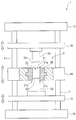
도 1 에는, 본 실시형태에 관련된 압축 성형 장치 (1) 의 개략도가 나타나 있다.Fig. 1 shows a schematic view of a
본 실시형태에서는, 유기 EL 소자용 재료를 가압 및 압축하여 압축 성형체를 제조한다.In this embodiment, a material for an organic EL device is pressed and compressed to produce a compression molded article.
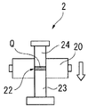
압축 성형 장치 (1) 는, 압축 성형 금형 (2) 과, 베이스부 (10) 와, 베이스부 (10) 에 서로 평행하게 입설된 2 개의 가이드 바 (11) 와, 가이드 바 (11) 의 상단에 연결된 상부 프레임 (12) 과, 베이스부 (10) 및 상부 프레임 (12) 사이에서 지지되어 있는 하부 가동판 (13), 중부 가동판 (14) 및 상부 가동판 (15) 을 구비한다. 도 1 에 나타내는 바와 같이, 하부 가동판 (13), 중부 가동판 (14) 및 상부 가동판 (15) 은, 베이스부 (10) 측으로부터 이 순서로 서로 평행하게 형성되어 있다. 또한, 하부 가동판 (13), 중부 가동판 (14) 및 상부 가동판 (15) 은, 가이드 바 (11) 를 따라 상하 방향으로 각각 독립적으로 이동 가능하게 형성되어 있다. 또한, 하부 가동판 (13), 중부 가동판 (14) 및 상부 가동판 (15) 은, 도시하지 않은 유압 실린더 등의 액체압식 구동 기구, 에어 실린더 등의 공기압식 구동 기구, 혹은 캠 혹은 크랭크 기구 등의 기계식 구동 기구에 의해 이동할 수 있도록 구성되어 있다.The
압축 성형 금형 (2) 은, 본체 (20) 와, 제 1 펀치 (23) 와, 이 제 1 펀치 (23) 와 대향하여 형성되는 제 2 펀치 (24) 를 구비한다. 본체 (20) 는, 중부 가동판 (14) 의 대략 중앙부에 교환 가능하게 장착되어 있다. 본체 (20) 는, 도 1 에 나타내는 바와 같이, 상하로 관통하는 관통공 (21) 을 갖는다. 이 관통공 (21) 에, 제 1 펀치 (23) 및 제 2 펀치 (24) 가 삽입되어, 압축 성형 금형 (2) 의 내부에 유기 EL 소자용 재료를 충전하기 위한 성형실 (22) 이 형성된다. 성형실 (22) 은, 성형해야 할 압축 성형체의 형상을 이루고 있다. 성형실 (22) 의 형상, 즉 압축 성형체의 형상은, 원주상이거나 타원주상이어도 되고, 횡단면이 반원형, 부채형, 삼각형, 사각형 등의 다각형이거나 소판 (小判) 형이어도 된다. 또한, 압축 성형체는, 중실체여도 되고 중공체여도 된다.The
제 1 펀치 (23) 및 제 2 펀치 (24) 는, 성형실 (22) 에 충전된 유기 EL 소자용 재료를 서로 반대 방향으로부터 가압하여 압축한다. 제 1 펀치 (23) 및 제 2 펀치 (24) 는, 관통공 (21) 에 삽입 가능하게 형성되어 있다.The
제 1 펀치 (23) 는, 하부 가동판 (13) 의 상면에 고정되어 있다. 제 1 펀치 (23) 는, 하부 가동판 (13) 이 상하 방향으로 이동함으로써, 관통공 (21) 의 축 방향으로 이동하도록 구성되어 있다. 제 1 펀치 (23) 는, 관통공 (21) 의 타방의 관통공 입구 (21b) 로부터 삽입된다. 제 2 펀치 (24) 는, 상부 가동판 (15) 의 하면에 고정되어 있다. 제 2 펀치 (24) 는, 상부 가동판 (15) 이 상하 방향으로 이동함으로써, 관통공 (21) 의 축 방향으로 이동하도록 구성되어 있다. 제 2 펀치 (24) 는, 관통공 (21) 의 일방의 관통공 입구 (21a) 로부터 삽입된다. 제 1 펀치 (23) 및 제 2 펀치 (24) 는, 관통공 (21) 보다 약간 작게 형성되어 있는 것이 바람직하다. 삽입된 제 1 펀치 (23) 의 측면과 관통공 (21) 의 내주면 (21c) 사이, 그리고 제 2 펀치 (24) 의 측면과 관통공 (21) 의 내주면 (21c) 사이에 간극이 형성되고, 성형실 (22) 내의 분말 재료로부터 탈기된 기체가, 당해 간극을 통과하여 배출되는 것이 바람직하다.The
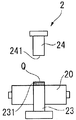
제 1 펀치 (23) 및 제 2 펀치 (24) 의 각각의 단부에는, 유기 EL 소자용 재료를 가압하는 제 1 가압면 (231) 및 제 2 가압면 (241) 이 형성되어 있다. 본 실시형태에서는, 제 1 펀치 (23) 의 제 1 가압면 (231) 및 제 2 펀치 (24) 의 제 2 가압면 (241) 은, 평탄한 면이다. 제 1 펀치 (23) 의 제 1 가압면 (231) 과 제 2 펀치 (24) 의 제 2 가압면 (241) 과 본체 (20) 의 관통공 (21) 의 내주면 (21c) 으로, 성형실 (22) 이 형성된다. 성형실 (22) 에 유기 EL 소자용 재료가 충전되고, 제 1 펀치 (23) 및 제 2 펀치 (24) 로 상하 방향으로부터 가압함으로써, 제 1 가압면 (231) 과 제 2 가압면 (241) 사이에서 압축되어 압축 성형체가 얻어진다.At each end of the
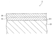
도 2 에는, 본 실시형태에 관련된 압축 성형 금형 (2) 의 표면의 일부로서, 제 1 펀치 (23) 의 일부를 확대하여 나타내는 단면 개략도가 나타나 있다.2 is a schematic cross-sectional view showing a part of the
제 1 펀치 (23) 의 제 1 가압면 (231) 은, 가압 및 압축시에 유기 EL 소자용 재료와 접촉하는 금속면이다. 도 2 에 나타내는 바와 같이, 제 1 가압면 (231) 에는, 질화물을 포함하는 질화물막 (25) 이 적층되어 있다. 또한, 질화물막 (25) 상에는, 불화물을 포함하는 불화물막 (26) 이 적층되어 있다.The first
제 2 펀치 (24) 의 제 2 가압면 (241), 및 본체 (20) 의 관통공 (21) 의 내주면 (21c) 도, 가압 및 압축시에 유기 EL 소자용 재료와 접촉하는 금속면이다. 제 2 가압면 (241), 및 내주면 (21c) 에도, 제 1 가압면 (231) 과 마찬가지로, 질화물막 (25) 및 불화물막 (26) 이 적층되어 있다. 본 실시형태에서는, 제 1 가압면 (231), 제 2 가압면 (241), 및 내주면 (21c) 에 적층된 불화물막 (26) 은, 침지법에 의해 형성되어 있다.The second
본 실시형태에 있어서, 질화물막 (25) 으로는, 질화티탄알루미늄, 질화티탄카바이드, 질화크롬, 질화티탄, 질화티탄실리콘, 및 질화티탄알루미늄실리콘으로 이루어지는 군에서 선택되는 질화물로 구성되는 것이 바람직하고, 질화티탄알루미늄으로 구성되는 것이 보다 바람직하다. 본 실시형태에서는, 질화물막 (25) 은, 물리 기상 증착법으로 성막한 질화티탄알루미늄으로 구성된다.In the present embodiment, the
불화물막 (26) 은, 불화탄소계 화합물로 구성되는 것이 바람직하다. 불화탄소계 화합물은, 불화탄소로 형성되는 사슬형 부위와, 다른 물질과 결합하는 반응기로 구성된다. 불화탄소계 화합물로는, 예를 들어, 퍼플루오로알킬실란류, 퍼플루오로폴리에테르기 함유 실란 화합물류 등을 들 수 있다.The
퍼플루오로알킬실란류로는, 하기 식 (1) 이나 식 (2) 로 나타내는 화합물을 들 수 있다.Examples of the perfluoroalkylsilanes include compounds represented by the following formulas (1) and (2).
CF3(CF2)nCH2CH2Si(OMe)m … (1)CF 3 (CF 2 ) n CH 2 CH 2 Si (OMe) m (One)
CF3(CF2)nCH2CH2Si(OR)m … (2)CF 3 (CF 2 ) n CH 2 CH 2 Si (OR) m (2)
단, 상기 식 (1) 에 있어서, n 은, 1, 3, 5, 또는 7 이고, m 은, 2 또는 3 이고, Me 는, 메틸기 또는 에틸기이다.In the above formula (1), n is 1, 3, 5, or 7, m is 2 or 3, and Me is a methyl group or an ethyl group.
또한, 상기 식 (2) 에 있어서, n 은, 1, 3, 5, 또는 7 이고, m 은, 2 또는 3 이고, R 은, 할로겐 원소이다.In the above formula (2), n is 1, 3, 5, or 7, m is 2 or 3, and R is a halogen element.
상기 식 (1) 이나 식 (2) 로 나타내는 화합물의 구체예로는, CF3(CF2)5CH2CH2Si(OCH3)3 (예를 들어, 모멘티브·퍼포먼스·머테리얼즈 제조의 TSL8257), CF3(CF2)7CH2CH2Si(OCH3)3 (예를 들어, 모멘티브·퍼포먼스·머테리얼즈 제조의 TSL8233), CF3(CF2)7CH2CH2Si(OCH3)2 (예를 들어, 모멘티브·퍼포먼스·머테리얼즈 제조의 TSL8231, 또는 신에츠 화학 공업 제조의 KBM7803), CF3(CF2)7CH2CH2Si(OC2H5)3 (예를 들어, 토오레·다우코닝 제조의 AY43-158E) 등을 들 수 있다.Specific examples of the compound represented by the above-mentioned formula (1) or (2) include CF 3 (CF 2 ) 5 CH 2 CH 2 Si (OCH 3 ) 3 (manufactured by Momentive Performance Materials of TSL8257), CF 3 (CF 2 ) 7
퍼플루오로폴리에테르기 함유 실란 화합물류에는, 퍼플루오로폴리에테르 변성 아미노실란, 퍼플루오로폴리에테르 변성 폴리실라잔 등이 있다. 구체적으로는, 예를 들어, 신에츠 화학 공업 제조의 KY-164, 다이킨 공업 제조의 오프툴 시리즈 등을 들 수 있다.Examples of the perfluoropolyether group-containing silane compounds include perfluoropolyether-modified aminosilane and perfluoropolyether-modified polysilazane. Specifically, for example, KY-164 manufactured by Shin-Etsu Chemical Industry Co., Ltd. and off-tool series manufactured by Daikin Industries Co., Ltd. can be mentioned.
불화물막 (26) 은, 침지법에 의해 형성되면 특별히 한정되지 않지만, 예를 들어, 불화탄소계 화합물을 함유하는 불화물 함유 용액에, 압축 성형 금형 (2) 을 침지시키고, 침지 후, 불화물 함유 용액을 건조시킴으로써 형성된다. 본 실시형태에서는, 제 1 펀치 (23), 제 2 펀치 (24) 및 본체 (20) 를 불화물 함유 용액에 침지시킨다. 그 때, 적어도, 제 1 가압면 (231), 제 2 가압면 (241), 및 내주면 (21c) 을 불화물 함유 용액에 침지시키고, 건조시켜, 각 면에 불화물막 (26) 을 형성시킨다.The
또한, 본 실시형태에서는, 제 1 가압면 (231), 제 2 가압면 (241), 및 내주면 (21c) 의 중심선 평균 거칠기 Ra 가 0.5 ㎛ 이하인 것이 바람직하고, 0.1 ㎛ 이하인 것이 보다 바람직하다. 본 실시형태에서는, 불화물막 (26) 이 각 면의 표층에 존재하기 때문에, 불화물막 (26) 표면의 중심선 평균 거칠기 Ra 가 0.5 ㎛ 이하이면, 압축 성형 후, 유기 EL 소자용 재료가 이들 면에 잘 부착하지 않게 되어, 압축 성형체로부터의 박리가 억제된다.In the present embodiment, the center line average roughness Ra of the first
압축 성형 장치 (1) 는, 성형실 (22) 내부에서 외부로 기체를 배출하는 탈기 수단을 갖는 것이 바람직하고, 압축 성형 금형 (2) 의 본체 (20), 제 1 펀치 (23) 및 제 2 펀치 (24) 의 적어도 어느 것이, 탈기 수단을 갖는 것이 바람직하다. 본 실시형태에서는, 제 1 펀치 (23) 는, 탈기 수단으로서의 도시하지 않은 진동 장치를 갖는다. 관통공 (21) 의 관통공 입구 (21b) 로부터 제 1 펀치 (23) 가 삽입되고, 관통공 (21) 의 내주면 (21c) 과 제 1 펀치 (23) 의 제 1 가압면 (231) 으로 형성된 오목부에 분말 재료를 충전한다. 충전 후, 제 1 펀치 (23) 를 당해 진동 장치에 의해 진동시킴으로써, 충전 상태의 분말 재료로부터 탈기하여 성형실 (22) 의 외부로 배출한다.The
(2) 압축 성형 금형의 제조 방법(2) Manufacturing method of compression mold
다음으로, 압축 성형 금형 (2) 의 제조 방법에 대하여 설명한다.Next, a method of manufacturing the compression-
먼저, 가압 및 압축시에 유기 EL 소자용 재료와 접촉하는 압축 성형 금형 (2) 의 금속면에, 질화물을 코팅하여 질화물막 (25) 을 형성하는 공정을 실시한다. 본 실시형태에서는, 적어도, 제 1 가압면 (231), 제 2 가압면 (241), 및 내주면 (21c) 에 질화물막 (25) 을 형성한다. 질화물막 (25) 은, 질화물을 각 면에 코팅함으로써 형성된다. 질화물막 (25) 은, 예를 들어, 물리 기상 증착 (Physical Vapor Deposition, PVD) 법이나 화학 기상 증착 (Chemical Vapor Deposition, CVD) 법 등에 의해 형성할 수 있다. 질화물막 (25) 의 형성 전에는, 제 1 펀치 (23) 의 표면, 제 2 펀치 (24) 의 표면, 그리고 본체 (20) 의 표면 및 내주면 (21c) 을 청정화해 두는 것이 바람직하다. 청정화 처리로는, 예를 들어, 표면 연마 처리, 유기 용매 등에 침지시켜 실시하는 초음파 세정 처리, 아르곤 이온 등에 의한 봄버드 처리 등을 들 수 있고, 이들 처리를 조합하여 실시해도 된다.First, a step of forming a
다음으로, 제 1 펀치 (23), 제 2 펀치 (24) 및 본체 (20) 를 불화물 함유 용액에 침지시킨다. 그 때, 적어도, 질화물막 (25) 이 형성되어 있는 제 1 가압면 (231), 제 2 가압면 (241), 및 내주면 (21c) 을 불화물 함유 용액에 침지시킨다. 그 후, 불화물 함유 용액을 건조시켜, 각 면에 불화물막 (26) 을 형성시킨다. 불화물 함유 용액은, 상온에서 건조시켜도 되고, 가열하여 건조시켜도 된다.Next, the
본 실시형태에서는, 불화물 함유 용액은, 불화물 및 용매를 포함한다. 불화물은, 상기 서술한 불화탄소계 화합물로 구성되는 것이 바람직하다. 용매로는, 불화물을 용해시킬 수 있는 용매이면 특별히 한정되지 않지만, 유기 용매가 바람직하다. 유기 용매로는, 예를 들어, 톨루엔, 자일렌 등의 방향족 탄화수소계 용매, 아세트산에틸, 아세트산부틸 등의 에스테르계 용매, 디옥산, 디에틸에테르 등의 에테르계 용매, 부틸알코올 등의 알코올계 용매, 메틸에틸케톤, 메틸이소부틸케톤 등의 케톤계 용매 등을 들 수 있다. 용매로는, 1 종류로 이루어지는 단독의 용매여도 되고, 복수 종류를 혼합시킨 혼합 용매여도 된다.In the present embodiment, the fluoride-containing solution includes a fluoride and a solvent. The fluoride is preferably composed of the fluorocarbon compound described above. The solvent is not particularly limited as long as it is a solvent capable of dissolving the fluoride, but an organic solvent is preferable. Examples of the organic solvent include aromatic hydrocarbon solvents such as toluene and xylene, ester solvents such as ethyl acetate and butyl acetate, ether solvents such as dioxane and diethyl ether, and alcohol solvents such as butyl alcohol , Ketone solvents such as methyl ethyl ketone and methyl isobutyl ketone, and the like. The solvent may be a single solvent composed of one kind, or a mixed solvent obtained by mixing a plurality of kinds.
불화물 함유 용액을 건조시킬 때에, 용매를 제거함과 함께, 불화물을 질화물막 (25) 에 화학 결합시켜 불화물막 (26) 을 형성하는 것이 바람직하다. 질화물막 (25) 에 불화물을 화학 결합시킬 때에는, 미리 질화물막 (25) 에 활성화 처리를 실시해 두는 것이 바람직하다. 활성화 처리에 의해 질화물막 (25) 의 표면에 활성화 처리를 실시하여 활성화층이 형성된다. 이 질화물막 (25) 의 표면에 형성된 활성화층에 대하여, 불화물을 화학 결합시키는 것이 바람직하다. 활성화층을 형성하기 위한 활성화 처리를 실시함으로써, 질화물막 (25) 의 표면에 부착된 오염이 분해되어 청정화되고, 질화물막 표면에는 분자 결합손을 갖는 활성화층이 형성되고, 이 분자 결합손에 수산기가 흡착되어, 불화탄소계 화합물의 반응기와 반응하여 결합하기 쉬워진다.When the fluoride-containing solution is dried, it is preferable to remove the solvent and chemically bond the fluoride to the
활성화 처리로는, 특별히 한정되지 않지만, 물리적인 방법으로는, 코로나 방전 처리, 플라즈마 처리, 자외선 조사 처리, 프레임 처리 등을 들 수 있다. 화학적인 방법으로는, 산 및 알칼리의 적어도 어느 용액에 침지시키는 처리, 산화제 처리, 오존 처리 등을 들 수 있다. 이들 활성화 처리 중에서도, 코로나 방전 처리, 플라즈마 처리, 자외선 조사 처리, 오존 처리가, 질화물막 (25) 의 표면의 손상을 방지할 수 있기 때문에 바람직하고, 플라즈마 처리 및 자외선 조사 처리가, 질화물막 (25) 의 표면을 활성화하는 효율이 높아 더욱 바람직하다.The activation treatment is not particularly limited, and examples of the physical treatment include a corona discharge treatment, a plasma treatment, an ultraviolet irradiation treatment, a frame treatment, and the like. Examples of the chemical method include a treatment of immersing in at least one of an acid and an alkali, an oxidizing agent treatment, and an ozone treatment. Among these activation treatments, the corona discharge treatment, the plasma treatment, the ultraviolet ray irradiation treatment and the ozone treatment are preferable because the surface of the
불화물막 (26) 을 형성한 후, 미반응의 불화물을 제거하는 공정을 실시하는 것이 바람직하다. 미반응 불화물을 제거함으로써 불화물막 (26) 의 표면, 즉 유기 EL 소자용 재료와 접촉하는 면을 청정하게 할 수 있다. 불화물을 제거하는 방법은, 특별히 한정되지 않지만, 용매로 불화물막 (26) 을 세정하는 것이 바람직하고, 불화물 함유 용액에 사용한 용매와 동일한 종류의 용매를 이용하여 세정하는 것이 보다 바람직하다.It is preferable to carry out a step of removing unreacted fluoride after the
이상과 같이 하여, 압축 성형 금형 (2) 의 제 1 펀치 (23), 제 2 펀치 (24), 및 본체 (20) 에, 질화물막 (25) 및 불화물막 (26) 을 포함하는 적층막이 형성된다.As described above, a laminated film including the
(3) 압축 성형체의 제조 방법(3) Manufacturing method of compression molded article
다음으로, 압축 성형 장치 (1), 및 압축 성형 금형 (2) 을 이용하여 실시하는 압축 성형체의 제조 방법에 대하여 설명한다.Next, a description will be given of a method of manufacturing a compression molded product which is carried out using the
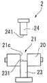
도 3a ∼ 도 3e 에는, 압축 성형체의 제조 방법의 각 공정에 있어서의 압축 성형 금형 (2) 의 본체 (20), 제 1 펀치 (23) 및 제 2 펀치 (24) 에 대하여 기재되고, 그 밖의 구성은 생략되어 있다. 압축 성형 금형 (2) 을 이용하여 실시하는 본 실시형태의 압축 성형체의 제조 방법은, 유기 EL 소자용 재료를 충전하고, 단축을 따른 가압력으로 성형하는 방법이다.3A to 3E describe the
먼저, 도 3a 에 나타내는 바와 같이, 제 1 가압면 (231) 을 관통공 (21) 의 내부를 향하여, 제 1 펀치 (23) 를 삽입한다. 이 때, 제 1 가압면 (231) 이 관통공 (21) 내의 소정 깊이 치수의 위치에 도달할 때까지 삽입한다. 이 깊이 치수는, 압축 성형체의 두께 치수 등에 의해 설정된다.First, as shown in Fig. 3A, the
다음으로, 도 3b 에 나타내는 바와 같이, 제 1 가압면 (231) 에 의해 저면이 형성된 관통공 (21) 의 내부에, 분말상의 유기 EL 소자용 재료 (P) 를 충전한다. 유기 EL 소자용 재료 (P) 를 충전 후, 제 1 펀치 (23) 를 전술한 진동 장치에 의해 진동시켜, 탈기 처리를 실시한다.Next, as shown in Fig. 3B, the powdery organic EL element-forming material P is filled in the through
다음으로, 도 3c 에 나타내는 바와 같이, 제 2 가압면 (241) 을 관통공 (21) 의 내부를 향하여, 제 2 펀치 (24) 를 삽입하고, 제 1 펀치 (23) 의 제 1 가압면 (231) 과 대향시킴으로써, 관통공 (21) 의 내주면 (21c) 과 제 1 가압면 (231) 과 제 2 가압면 (241) 으로, 성형실 (22) 을 형성한다. 그리고, 제 1 가압면 (231) 과 제 2 가압면 (241) 사이에서 유기 EL 소자용 재료 (P) 를 압축함으로써, 압축 성형체 (Q) 가 성형된다. 본 실시형태에서는, 제 1 펀치 (23) 및 제 2 펀치 (24) 가 이동하여, 유기 EL 소자용 재료 (P) 를 양측으로부터 가압하는 양압 방식으로 실시하는 예를 들어 설명하지만, 이 방식에 한정되지 않는다.Next, as shown in FIG. 3C, the
압축 압력은, 11 ㎫ 이상인 것이 바람직하다. 또한, 본체 (20) 의 내주면 (21c), 제 1 펀치 (23) 의 제 1 가압면 (231), 및 제 2 펀치 (24) 의 제 2 가압면 (241) 의 표면 온도가, 10 ℃ 이상인 것이 바람직하다.The compression pressure is preferably 11 MPa or more. The surface temperature of the inner
다음으로, 도 3d 에 나타내는 바와 같이, 제 1 펀치 (23) 의 제 1 가압면 (231) 과 제 2 펀치 (24) 의 제 2 가압면 (241) 사이에서 압축 성형체 (Q) 를 사이에 둔 채로, 제 1 펀치 (23) 및 제 2 펀치 (24) 를 상승 이동시켜, 압축 성형체 (Q) 를 관통공 (21) 으로부터 빼낸다. 제 1 펀치 (23) 및 제 2 펀치 (24) 의 상승 이동은, 제 1 펀치 (23) 의 제 1 가압면 (231) 이, 본체 (20) 의 상면과 일치한 시점에서 정지하는 것이 바람직하다. 제 1 펀치 (23) 및 제 2 펀치 (24) 는, 압축 성형체 (Q) 에 작용하고 있는 응력이 단번에 해방되지 않도록, 저속도로 상승 이동시키는 것이 바람직하다.Next, as shown in Fig. 3D, a pressurized object (Q) is sandwiched between the
다음으로, 도 3e 에 나타내는 바와 같이, 제 2 펀치 (24) 를 상승 이동시켜, 압축 성형체 (Q) 의 상면을 개방한다. 그 후, 제 1 가압면 (231) 상에 재치되어 있는 압축 성형체 (Q) 를 취출한다. 이와 같이 하여 유기 EL 소자용 재료를 압축하여 얻은 압축 성형체 (Q) 를 이용하여, 유기 EL 소자의 제조 방법을 실시하는 것이 바람직하다.Next, as shown in Fig. 3E, the
본 실시형태의 유기 EL 소자용 재료는, 결합제나 활택제 등의 성형 보조제가 혼합되어 있지 않다. 유기 EL 소자용 재료는, 유기 EL 소자에 사용되는 재료로서 특별히 한정되지 않고, 예를 들어, 정공 수송층에 사용되는 정공 수송성 재료, 발광층에 사용되는 호스트 재료, 도펀트 재료, 전자 수송층에 사용되는 전자 수송성 재료 등을 들 수 있다. 또한, 유기 EL 소자용 재료는, 복수 종류의 유기 EL 소자용 재료가 혼합되어 구성되어 있어도 된다.The organic EL device material of the present embodiment is not mixed with a molding aid such as a binder or a lubricant. The material for the organic EL device is not particularly limited as a material used for the organic EL device, and examples thereof include a hole transporting material used for the hole transporting layer, a host material used for the light emitting layer, a dopant material, Materials and the like. Further, the material for the organic EL device may be constituted by mixing a plurality of types of materials for the organic EL device.
본 실시형태에 있어서, 성형 전의 유기 EL 소자용 재료 (P) 의 평균 입경 D50 (메디안 직경) 은, 작은 것이 바람직하다. 유기 EL 소자용 재료 (P) 의 평균 입경 D50 이 작아질수록, 압축 성형체의 경도를 향상시킬 수 있다. 유기 EL 소자용 재료 (P) 의 평균 입경 D50 은, 70 ㎛ 이하인 것이 바람직하고, 45 ㎛ 이하인 것이 보다 바람직하고, 30 ㎛ 이하인 것이 더욱 바람직하다. 유기 EL 소자용 재료 (P) 의 입경 분포에 있어서, 최대 입경과 최소 입경의 차가 작은 것이 바람직하다.In the present embodiment, the average particle diameter D50 (median diameter) of the organic EL device material P before molding is preferably small. The smaller the average particle diameter D50 of the material (P) for an organic EL device, the higher the hardness of the compression-molded article. The average particle diameter D50 of the material (P) for an organic EL device is preferably 70 mu m or less, more preferably 45 mu m or less, and further preferably 30 mu m or less. It is preferable that the difference between the maximum particle diameter and the minimum particle diameter is small in the particle diameter distribution of the material (P) for an organic EL device.
또한, 유기 EL 소자용 재료 (P) 의 평균 입경 D50 이, 상기 서술한 바람직한 범위를 만족하고 있는 것이 본 실시형태에 있어서 바람직하다.It is preferable in the present embodiment that the average particle diameter D50 of the material (P) for an organic EL device satisfies the above-described preferable range.
(3) 본 실시형태의 효과(3) Effect of the present embodiment
본 실시형태에 관련된 압축 성형 금형 (2) 에서는, 유기 EL 소자용 재료 (P) 가 충전되는 성형실 (22) 은, 제 1 펀치 (23) 의 제 1 가압면 (231), 제 2 펀치 (24) 의 제 2 가압면 (241), 및 본체 (20) 의 관통공 (21) 의 내주면 (21c) 으로 형성된다. 제 1 가압면 (231), 제 2 가압면 (241), 및 내주면 (21c) 에는, 질화물막 (25) 및 불화물막 (26) 이 적층되어 있다. 불화물막 (26) 은, 침지법에 의해 형성되어 있다. 그 결과, 압축 성형 후에 압축 성형체 (Q) 로부터 재료가 부분적으로 박리되거나, 성형체 표면으로부터 분말이 비산하는 것을 억제할 수 있다. 또한, 압축 성형체 (Q) 의 표면을 매끄럽게 성형할 수 있다. 침지법에 의해 불화물막 (26) 이 제 1 가압면 (231), 제 2 가압면 (241), 및 내주면 (21c) 에 균일 형성되어 있기 때문인 것으로 생각된다.In the compression molding die 2 according to the present embodiment, the
또한, 종래, 솔칠 등의 도포법으로 불화물 함유 용액을 도포하고, 가열 건조로 불화물막을 형성하고 있지만, 이와 같은 방법으로는, 불화물막이 균일하게 형성되기 어렵고, 유기 EL 소자용 재료가 금형 표면에 부착되기 쉬워, 압축 성형체의 표면은, 거칠어지게 된다. 그 결과, 압축 성형체로부터 재료가 부분적으로 박리되거나, 성형체 표면으로부터 분말이 비산하는 양이 증가하게 되어, 성형 후의 압축 성형체의 중량이 10 % 이상 감소하여, 중량 감소가 현저하다.In addition, in the prior art, a fluoride-containing solution is coated by a coating method such as a brushing method, and a fluoride film is formed by heating and drying. However, such a method makes it difficult to uniformly form a fluoride film, And the surface of the compression-molded body becomes rough. As a result, the amount of the material partially peeled from the compression-molded body or scattered from the surface of the molded body increases, and the weight of the molded body after molding is reduced by 10% or more.
본 실시형태에서는, 유기 EL 소자용 재료 (P) 를 충전 후, 제 1 펀치 (23) 를 전술한 진동 장치에 의해 진동시켜, 탈기 처리를 실시함으로써, 충전된 유기 EL 소자용 재료 (P) 중에 포함되어 있던 기체를 제거할 수 있다. 또한, 본 실시형태에서는, 제 1 가압면 (231) 과 제 2 가압면 (241) 사이에서 유기 EL 소자용 재료 (P) 를 압축할 때의 압축 압력은, 11 ㎫ 이상이다. 그 결과, 유기 EL 소자용 재료 (P) 의 입자끼리가 보다 밀하게 충전되고, 압축 성형 후에 압축 성형체 (Q) 로부터 재료가 부분적으로 박리되거나, 성형체 표면으로부터 분말이 비산하는 것을 억제할 수 있다.In this embodiment, after the organic P-element material P is filled, the
본 실시형태에서는, 성형 보조제가 함유되어 있지 않은 유기 EL 소자용 재료를 예로 들어 설명하였다. 성형 후의 박리 등이 발생한 압축 성형체는, 그 경도가 충분하지 않다. 그 결과, 압축 성형체의 균열 등이 발생함으로써, 압축 성형체의 중량을 정확하게 파악하는 것이 곤란해져, 유기 EL 소자의 생산성의 향상을 도모할 수 없다. 한편으로, 본 실시형태에 관련된 압축 성형 금형 (2), 및 압축 성형 금형 (2) 을 사용한 압축 성형체의 제조 방법에 의하면, 압축 성형체 (Q) 로부터 재료가 부분적으로 박리되거나, 성형체 표면으로부터 분말이 비산하는 것을 억제할 수 있다. 그 때문에, 증착원에 대한 압축 성형체의 공급 횟수를 줄일 수 있어, 유기 EL 소자의 생산성의 향상을 도모할 수 있다.In the present embodiment, an organic EL device material not containing a molding assistant has been described as an example. The compression molded body in which peeling or the like occurs after molding is not sufficiently hard. As a result, it is difficult to accurately grasp the weight of the compression-molded article due to occurrence of cracks or the like of the compression-molded article, and the productivity of the organic EL device can not be improved. On the other hand, according to the compression-
또한, 제 1 가압면 (231), 제 2 가압면 (241), 및 내주면 (21c) 에 있어서는, 불화물막 (26) 의 내층측에 질화물막 (25) 이 형성되어 있기 때문에, 불화물막 (26) 의 내마모성을 향상시킬 수 있다.Since the
<변형예><Modifications>
또한, 본 발명은, 상기 서술한 실시형태에 한정되는 것이 아니고, 본 발명의 목적을 달성할 수 있는 범위에서, 이하에 나타내는 변형 등도 포함한다.The present invention is not limited to the above-described embodiments, but includes the modifications and the like described below within the scope of achieving the object of the present invention.
압축 성형 금형 (2) 의 금속면에 적층시키는 적층막은, 상기 실시형태의 구성에 한정되지 않는다. 예를 들어, 질화물막 (25) 과 불화물막 (26) 사이에, 전술한 활성화층과는 상이한 층을 개재시켜도 되고, 활성화층의 형성을 생략하고 직접, 질화물막 (25) 과 불화물막 (26) 을 적층시킨 2 층 구성의 적층막으로 해도 된다.The laminated film laminated on the metal surface of the compression-
압축 성형 장치 (1) 에 형성되는 탈기 수단은, 진동 장치에 한정되지 않고, 예를 들어, 초음파 발생 장치, 태핑 장치, 진공 탈기 장치여도 된다. 탈기 수단으로는, 성형실 (22) 에 충전된 분말 재료로부터 탈기할 수 있으면 된다. 또한, 탈기 수단은, 제 1 펀치 (23) 에 형성되는 경우에 한정되지 않고, 제 2 펀치 (24) 나 본체 (20) 에 형성되어 있어도 된다.The degassing means formed in the
압축 성형 금형 (2) 의 관통공 (21) 의 관통공 입구 (21a) 에는 테이퍼 가공이 실시되어 있어도 된다. 이 테이퍼 가공은, 관통공 (21) 의 내부로부터 관통공 입구 (21a) 를 향하여 구멍 지름이 확대되도록 실시되어 있다. 이 테이퍼 가공 부분에 있어서도, 질화물막 (25) 및 불화물막 (26) 의 적층막이 형성되어 있는 것이 바람직하다. 또한, 관통공 입구 (21b) 에도 테이퍼 가공이 실시되어 있어도 된다.The through-
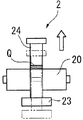
또한, 압축 성형체 (Q) 를 압축 성형 금형 (2) 으로부터 빼내는 방법은, 상기 실시형태에서 설명한 방법에 한정되지 않는다.The method of extracting the compression-molded body Q from the compression-
예를 들어, 도 4a 에 나타내는 바와 같이, 본체 (20) 를 하강 이동시킨다. 도 4b 에 나타내는 바와 같이, 본체 (20) 의 하강 이동은, 본체 (20) 의 상면이, 제 1 펀치 (23) 의 제 1 가압면 (231) 과 일치한 시점에서 정지하는 것이 바람직하다. 본체 (20) 는, 압축 성형체 (Q) 에 작용하고 있는 응력이 단번에 해방되지 않도록, 저속도로 하강 이동시키는 것이 바람직하다. 다음으로, 도 4c 에 나타내는 바와 같이, 제 2 펀치 (24) 를 상승 이동시켜, 압축 성형체 (Q) 의 상면을 개방한다. 그 후, 제 1 가압면 (231) 상에 재치되어 있는 압축 성형체 (Q) 를 취출한다.For example, as shown in Fig. 4A, the
압축 성형 방법은, 상기 실시형태에서 설명한 방법에 한정되지 않는다. 예를 들어, 플로팅 다이 방식에 의해 압축 성형을 실시해도 된다. 플로팅 다이 방식으로는, 제 2 펀치 (24) 로 가압하고, 본체 (20) 의 관통공 (21) 의 내주면 (21c) 과, 유기 EL 소자용 재료 사이에서 마찰력이 점차 증대하여, 본체 (20) 의 지지력보다 커지면, 본체 (20) 는 중부 가동판 (14) 과 함께 하강한다. 이 때, 제 1 펀치 (23) 는, 상대적으로 상승한 것이 된다. 그 후, 제 2 펀치 (24) 를 상승시켜, 압축 성형체를 취출한다. 이와 같은 플로팅 다이 방식에 의하면, 압축 성형체의 두께 방향에서의 밀도 조정이 가능해진다. 그 외에, 위드드로얼 방식이나, 제 2 펀치 (24) 만이 하강하는 편압 방식 등을 채용할 수 있다. 이들 방식을 채용하는 경우에 있어서도, 제 1 펀치 (23) 의 제 1 가압면 (231), 제 2 펀치 (24) 의 제 2 가압면 (241), 및 본체 (20) 의 관통공 (21) 의 내주면 (21c) 에, 질화물막 (25) 및 불화물막 (26) 의 적층막을 형성함으로써, 압축 성형 후에 압축 성형체 (Q) 로부터 재료가 부분적으로 박리되거나, 성형체 표면으로부터 분말이 비산하는 것을 억제할 수 있다.The compression molding method is not limited to the method described in the above embodiment. For example, compression molding may be performed by a floating die method. The pressing force is applied by the
또한, 압축 성형 금형에 관해서도, 상기 실시형태에서 설명한 기구나 형상 등에 한정되지 않고, 분말상의 재료를 가압 및 압축하여, 압축 성형체를 형성할 수 있는 기구 및 형상의 금형이면 된다.The compression molding die is not limited to the mechanism, the shape, and the like described in the above embodiments, but may be a mold having a mechanism and a shape capable of pressing and compressing a powdery material to form a compression molded body.
1 ; 압축 성형 장치
2 ; 압축 성형 금형
21 ; 관통공
21a, 21b ; 관통공 입구
21c ; 내주면
22 ; 성형실
23 ; 제 1 펀치
231 ; 제 1 가압면
24 ; 제 2 펀치
241 ; 제 2 가압면
P ; 분말 재료
Q ; 압축 성형체One ; Compression molding device
2 ; Compression mold
21; Through-hole
21a, 21b; Penetrating ball entrance
21c; Inner circumferential surface
22; Molding room
23; The first punch
231; The first pressing surface
24; The second punch
241; The second pressing surface
P; Powder material
Q; Compression molding body
Claims (13)
상기 관통공의 내주면에도 상기 질화물막 및 상기 불화물막이 적층되어 있는 압축 성형 금형.3. The method of claim 2,
And the nitride film and the fluoride film are also laminated on the inner peripheral surface of the through hole.
상기 질화물막은, 질화티탄알루미늄, 질화티탄카바이드, 질화크롬, 질화티탄, 질화티탄실리콘, 및 질화티탄알루미늄실리콘으로 이루어지는 군에서 선택되는 질화물로 구성되는 압축 성형 금형.4. The method according to any one of claims 1 to 3,
Wherein the nitride film is composed of a nitride selected from the group consisting of titanium aluminum nitride, titanium nitride carbide, chromium nitride, titanium nitride, titanium nitride silicon, and titanium aluminum nitride silicon.
상기 불화물은, 불화탄소계 화합물인 압축 성형 금형.5. The method according to any one of claims 1 to 4,
Wherein the fluoride is a fluorocarbon compound.
상기 불화물 함유 용액은, 상기 불화물 및 용매를 포함하고, 상기 불화물막을 형성하는 공정으로, 상기 용매를 제거함과 함께, 상기 불화물을 상기 질화물막에 화학 결합시켜 상기 불화물막을 형성하고, 상기 불화물막을 형성한 후에, 미반응의 불화물을 제거하는 압축 성형 금형의 제조 방법.The method according to claim 6,
Wherein the fluoride-containing solution contains the fluoride and a solvent, and in the step of forming the fluoride film, the solvent is removed and the fluoride is chemically bonded to the nitride film to form the fluoride film, And subsequently removing the unreacted fluoride.
상기 미반응의 불화물을 제거할 때에, 상기 불화물 함유 용액에 포함되어 있던 상기 용매와 동일한 종류의 용매로 상기 불화물막을 세정하는 압축 성형 금형의 제조 방법.8. The method of claim 7,
Wherein the fluoride film is washed with a solvent of the same kind as the solvent contained in the fluoride-containing solution when the unreacted fluoride is removed.
상기 질화물막에, 코로나 방전 처리, 플라즈마 처리, 자외선 조사 처리, 프레임 처리, 산 및 알칼리의 적어도 어느 용액에 침지시키는 처리, 산화제 처리, 그리고 오존 처리 중 적어도 어느 것의 활성화 처리를 실시한 후에, 상기 질화물막이 형성된 면을 상기 불화물 함유 용액에 침지시키는 압축 성형 금형의 제조 방법.9. The method according to any one of claims 6 to 8,
After the nitride film is subjected to activation treatment of at least one of a corona discharge treatment, a plasma treatment, an ultraviolet ray irradiation treatment, a frame treatment, a treatment of immersing in at least any solution of an acid and an alkali, an oxidizing agent treatment and an ozone treatment, And the formed surface is immersed in the fluoride-containing solution.
상기 활성화 처리는, 코로나 방전 처리, 플라즈마 처리, 자외선 조사 처리, 또는 오존 처리인 압축 성형 금형의 제조 방법.10. The method of claim 9,
Wherein the activation treatment is a corona discharge treatment, a plasma treatment, an ultraviolet irradiation treatment, or an ozone treatment.
상기 활성화 처리는, 플라즈마 처리 또는 자외선 조사 처리인 압축 성형 금형의 제조 방법.10. The method of claim 9,
Wherein the activation treatment is a plasma treatment or an ultraviolet ray irradiation treatment.
상기 질화물막은, 질화티탄알루미늄, 질화티탄카바이드, 질화크롬, 질화티탄, 질화티탄실리콘, 및 질화티탄알루미늄실리콘으로 이루어지는 군에서 선택되는 질화물로 구성되는 압축 성형체의 제조 방법.13. The method of claim 12,
Wherein the nitride film is composed of a nitride selected from the group consisting of titanium aluminum nitride, titanium nitride carbide, chromium nitride, titanium nitride, titanium nitride silicon, and titanium aluminum nitride silicon.
Applications Claiming Priority (3)
| Application Number | Priority Date | Filing Date | Title |
|---|---|---|---|
| JPJP-P-2014-072910 | 2014-03-31 | ||
| JP2014072910A JP6096147B2 (en) | 2014-03-31 | 2014-03-31 | Method for manufacturing compression mold and method for manufacturing compression molded body |
| PCT/JP2015/058182 WO2015151825A1 (en) | 2014-03-31 | 2015-03-19 | Compression molding die, production method for compression molding die, and production method for compression-molded article |
Publications (1)
| Publication Number | Publication Date |
|---|---|
| KR20160137938A true KR20160137938A (en) | 2016-12-02 |
Family
ID=54240156
Family Applications (1)
| Application Number | Title | Priority Date | Filing Date |
|---|---|---|---|
| KR1020167001174A KR20160137938A (en) | 2014-03-31 | 2015-03-19 | Compression molding die, production method for compression molding die, and production method for compression-molded article |
Country Status (4)
| Country | Link |
|---|---|
| JP (1) | JP6096147B2 (en) |
| KR (1) | KR20160137938A (en) |
| CN (1) | CN105408081B (en) |
| WO (1) | WO2015151825A1 (en) |
Families Citing this family (1)
| Publication number | Priority date | Publication date | Assignee | Title |
|---|---|---|---|---|
| DE102016125406A1 (en) | 2016-12-22 | 2018-06-28 | Gkn Sinter Metals Engineering Gmbh | Die for a press |
Citations (3)
| Publication number | Priority date | Publication date | Assignee | Title |
|---|---|---|---|---|
| JPH02297411A (en) | 1989-02-01 | 1990-12-07 | Chisso Corp | Mold release agent for powder molding and manufacture of molding using the same agent |
| KR20090097318A (en) | 2008-03-11 | 2009-09-16 | 박진연 | Die assembly for tablet |
| JP3163163U (en) | 2010-07-21 | 2010-09-30 | 株式会社ジェピア | Mold |
Family Cites Families (13)
| Publication number | Priority date | Publication date | Assignee | Title |
|---|---|---|---|---|
| JPH03254910A (en) * | 1989-07-11 | 1991-11-13 | Hitachi Tool Eng Ltd | Die for molding plastic |
| JPH03216298A (en) * | 1990-01-19 | 1991-09-24 | Idemitsu Kosan Co Ltd | Compression molding method |
| JP2849162B2 (en) * | 1990-02-27 | 1999-01-20 | 日本タングステン株式会社 | Mold for resin molding |
| JP3837928B2 (en) * | 1998-08-21 | 2006-10-25 | 住友電気工業株式会社 | Member for resin molding apparatus and method for manufacturing the same |
| JP2002001733A (en) * | 2000-06-26 | 2002-01-08 | Fuji Dies Kk | Mold for molding tablet of resin for sealing semiconductor |
| US7153592B2 (en) * | 2000-08-31 | 2006-12-26 | Fujitsu Limited | Organic EL element and method of manufacturing the same, organic EL display device using the element, organic EL material, and surface emission device and liquid crystal display device using the material |
| JP3292199B2 (en) * | 2001-03-22 | 2002-06-17 | 住友電気工業株式会社 | Rubber mold, method for manufacturing rubber mold, and method for molding rubber |
| US7238383B2 (en) * | 2003-03-07 | 2007-07-03 | Eastman Kodak Company | Making and using compacted pellets for OLED displays |
| JP4582497B2 (en) * | 2004-02-27 | 2010-11-17 | 株式会社ダイヤメット | Molding method of powder compact |
| JP5516653B2 (en) * | 2006-10-06 | 2014-06-11 | 日立化成株式会社 | Tablet molding die, tablet, optical semiconductor element mounting substrate manufacturing method, and optical semiconductor device. |
| JP2008112977A (en) * | 2006-10-06 | 2008-05-15 | Hitachi Chem Co Ltd | Tablet molding die, tablet, manufacturing method for optical semiconductor element-mounting substrate and optical semiconductor device |
| JP2012056246A (en) * | 2010-09-10 | 2012-03-22 | Fujifilm Corp | Ni MASTER HAVING FINE UNEVEN PATTERN ON SURFACE AND METHOD OF MANUFACTURING Ni REPLICATION USING THE SAME |
| JP5725339B2 (en) * | 2011-03-25 | 2015-05-27 | 株式会社小糸製作所 | Hot plate welding jig and manufacturing method thereof, metal member |
-
2014
- 2014-03-31 JP JP2014072910A patent/JP6096147B2/en not_active Expired - Fee Related
-
2015
- 2015-03-19 KR KR1020167001174A patent/KR20160137938A/en not_active Application Discontinuation
- 2015-03-19 WO PCT/JP2015/058182 patent/WO2015151825A1/en active Application Filing
- 2015-03-19 CN CN201580001414.9A patent/CN105408081B/en not_active Expired - Fee Related
Patent Citations (3)
| Publication number | Priority date | Publication date | Assignee | Title |
|---|---|---|---|---|
| JPH02297411A (en) | 1989-02-01 | 1990-12-07 | Chisso Corp | Mold release agent for powder molding and manufacture of molding using the same agent |
| KR20090097318A (en) | 2008-03-11 | 2009-09-16 | 박진연 | Die assembly for tablet |
| JP3163163U (en) | 2010-07-21 | 2010-09-30 | 株式会社ジェピア | Mold |
Also Published As
| Publication number | Publication date |
|---|---|
| JP2015193175A (en) | 2015-11-05 |
| JP6096147B2 (en) | 2017-03-15 |
| WO2015151825A1 (en) | 2015-10-08 |
| CN105408081B (en) | 2019-03-22 |
| CN105408081A (en) | 2016-03-16 |
Similar Documents
| Publication | Publication Date | Title |
|---|---|---|
| KR101698289B1 (en) | Mold release film and semiconductor package manufacturing method | |
| JP5796449B2 (en) | Manufacturing method of electronic device, manufacturing method of carrier substrate with resin layer | |
| TWI654088B (en) | Object and method for controlled engagement of a polymer surface with a carrier | |
| KR102237812B1 (en) | Glass articles and methods for controlled bonding of glass sheets with carriers | |
| JP2017500259A (en) | Glass article and method for controlled bonding of glass sheet and carrier | |
| TW201529511A (en) | Treatment of a surface modification layer for controlled bonding of thin sheets with carriers | |
| TW201736292A (en) | Bulk annealing of glass sheets | |
| WO2014041904A1 (en) | Method for manufacturing laminate provided with uneven shape, and transfer film | |
| CN1445826A (en) | Method for cleaning plasma processing device | |
| KR101553962B1 (en) | Adhesive composition and adhesive method thereof and separating method after adhesion | |
| KR20160137937A (en) | Compression molding device and production method for compression-molded article | |
| KR20160137938A (en) | Compression molding die, production method for compression molding die, and production method for compression-molded article | |
| TW201728433A (en) | Water-repellent member and method for manufacturing same | |
| CN1736830A (en) | Substrate transfer device and cleaning method thereof and substrate processing system and cleaning method thereof | |
| TW201519329A (en) | Electronic device sealing method, electronic device package production method, and sealing sheet | |
| KR20140122861A (en) | Adhesion pad and method of manufacturing the same | |
| US11548194B2 (en) | Method for manufacturing fluid device composite member | |
| CN1275885C (en) | Reproducing method for forming die and method for making optical element | |
| KR102365285B1 (en) | Method and Device for Coating a Product Substrate | |
| TWI814282B (en) | Adhesive Film Applied to Wafer Fat Edge Removal and Its Removal Method | |
| CN217830595U (en) | Glue film applied to removal of wafer fat edge | |
| CN218342650U (en) | Demoulding device | |
| KR20100090941A (en) | Flexible membrane for chemical mechanical polishing apparatus | |
| JP2010505634A (en) | Contaminant removal method with dry ice | |
| KR102027529B1 (en) | Method for transferring thin films using liquid |
Legal Events
| Date | Code | Title | Description |
|---|---|---|---|
| A201 | Request for examination | ||
| E902 | Notification of reason for refusal | ||
| E601 | Decision to refuse application |