WO2015151825A1 - Compression molding die, production method for compression molding die, and production method for compression-molded article - Google Patents
Compression molding die, production method for compression molding die, and production method for compression-molded article Download PDFInfo
- Publication number
- WO2015151825A1 WO2015151825A1 PCT/JP2015/058182 JP2015058182W WO2015151825A1 WO 2015151825 A1 WO2015151825 A1 WO 2015151825A1 JP 2015058182 W JP2015058182 W JP 2015058182W WO 2015151825 A1 WO2015151825 A1 WO 2015151825A1
- Authority
- WO
- WIPO (PCT)
- Prior art keywords
- compression
- fluoride
- nitride
- film
- organic
- Prior art date
Links
Images


Classifications
-
- B—PERFORMING OPERATIONS; TRANSPORTING
- B29—WORKING OF PLASTICS; WORKING OF SUBSTANCES IN A PLASTIC STATE IN GENERAL
- B29C—SHAPING OR JOINING OF PLASTICS; SHAPING OF MATERIAL IN A PLASTIC STATE, NOT OTHERWISE PROVIDED FOR; AFTER-TREATMENT OF THE SHAPED PRODUCTS, e.g. REPAIRING
- B29C33/00—Moulds or cores; Details thereof or accessories therefor
- B29C33/38—Moulds or cores; Details thereof or accessories therefor characterised by the material or the manufacturing process
-
- B—PERFORMING OPERATIONS; TRANSPORTING
- B29—WORKING OF PLASTICS; WORKING OF SUBSTANCES IN A PLASTIC STATE IN GENERAL
- B29C—SHAPING OR JOINING OF PLASTICS; SHAPING OF MATERIAL IN A PLASTIC STATE, NOT OTHERWISE PROVIDED FOR; AFTER-TREATMENT OF THE SHAPED PRODUCTS, e.g. REPAIRING
- B29C43/00—Compression moulding, i.e. applying external pressure to flow the moulding material; Apparatus therefor
- B29C43/006—Pressing and sintering powders, granules or fibres
-
- B—PERFORMING OPERATIONS; TRANSPORTING
- B29—WORKING OF PLASTICS; WORKING OF SUBSTANCES IN A PLASTIC STATE IN GENERAL
- B29C—SHAPING OR JOINING OF PLASTICS; SHAPING OF MATERIAL IN A PLASTIC STATE, NOT OTHERWISE PROVIDED FOR; AFTER-TREATMENT OF THE SHAPED PRODUCTS, e.g. REPAIRING
- B29C43/00—Compression moulding, i.e. applying external pressure to flow the moulding material; Apparatus therefor
- B29C43/32—Component parts, details or accessories; Auxiliary operations
- B29C43/36—Moulds for making articles of definite length, i.e. discrete articles
- B29C43/361—Moulds for making articles of definite length, i.e. discrete articles with pressing members independently movable of the parts for opening or closing the mould, e.g. movable pistons
-
- B—PERFORMING OPERATIONS; TRANSPORTING
- B30—PRESSES
- B30B—PRESSES IN GENERAL
- B30B15/00—Details of, or accessories for, presses; Auxiliary measures in connection with pressing
- B30B15/02—Dies; Inserts therefor; Mounting thereof; Moulds
- B30B15/022—Moulds for compacting material in powder, granular of pasta form
-
- H—ELECTRICITY
- H01—ELECTRIC ELEMENTS
- H01B—CABLES; CONDUCTORS; INSULATORS; SELECTION OF MATERIALS FOR THEIR CONDUCTIVE, INSULATING OR DIELECTRIC PROPERTIES
- H01B1/00—Conductors or conductive bodies characterised by the conductive materials; Selection of materials as conductors
- H01B1/04—Conductors or conductive bodies characterised by the conductive materials; Selection of materials as conductors mainly consisting of carbon-silicon compounds, carbon or silicon
-
- H—ELECTRICITY
- H10—SEMICONDUCTOR DEVICES; ELECTRIC SOLID-STATE DEVICES NOT OTHERWISE PROVIDED FOR
- H10K—ORGANIC ELECTRIC SOLID-STATE DEVICES
- H10K71/00—Manufacture or treatment specially adapted for the organic devices covered by this subclass
- H10K71/10—Deposition of organic active material
- H10K71/12—Deposition of organic active material using liquid deposition, e.g. spin coating
-
- B—PERFORMING OPERATIONS; TRANSPORTING
- B29—WORKING OF PLASTICS; WORKING OF SUBSTANCES IN A PLASTIC STATE IN GENERAL
- B29C—SHAPING OR JOINING OF PLASTICS; SHAPING OF MATERIAL IN A PLASTIC STATE, NOT OTHERWISE PROVIDED FOR; AFTER-TREATMENT OF THE SHAPED PRODUCTS, e.g. REPAIRING
- B29C43/00—Compression moulding, i.e. applying external pressure to flow the moulding material; Apparatus therefor
- B29C43/32—Component parts, details or accessories; Auxiliary operations
- B29C43/36—Moulds for making articles of definite length, i.e. discrete articles
- B29C43/361—Moulds for making articles of definite length, i.e. discrete articles with pressing members independently movable of the parts for opening or closing the mould, e.g. movable pistons
- B29C2043/3615—Forming elements, e.g. mandrels or rams or stampers or pistons or plungers or punching devices
- B29C2043/3628—Forming elements, e.g. mandrels or rams or stampers or pistons or plungers or punching devices moving inside a barrel or container like sleeve
-
- H—ELECTRICITY
- H10—SEMICONDUCTOR DEVICES; ELECTRIC SOLID-STATE DEVICES NOT OTHERWISE PROVIDED FOR
- H10K—ORGANIC ELECTRIC SOLID-STATE DEVICES
- H10K50/00—Organic light-emitting devices
- H10K50/10—OLEDs or polymer light-emitting diodes [PLED]
- H10K50/11—OLEDs or polymer light-emitting diodes [PLED] characterised by the electroluminescent [EL] layers
Definitions
- the present invention relates to a compression mold, a method for manufacturing a compression mold, and a method for manufacturing a compression molded body.
- An object of the present invention is to manufacture a compression mold and a compression mold that can prevent the material from partially peeling from the molded body or the powder from being scattered from the surface of the molded body after compression molding of the powder material. It is providing the method and the manufacturing method of a compression molding body.
- a compression molding die for forming a compression molded body by pressurizing and compressing an organic EL element material, wherein the compression molding is brought into contact with the organic EL element material during compression.
- a compression mold in which a nitride film containing nitride is laminated on the metal surface of the mold, and a fluoride film containing fluoride formed by an immersion method is laminated on the nitride film. Is done.
- a main body having a through-hole and an organic EL element material inserted from different through-hole inlets of the through-hole and filled in a molding chamber inside the main body are added.
- a first punch and a second punch each provided with a pressing surface for pressing, and a nitride film containing nitride and a fluoride film containing fluoride formed by dipping are stacked on the pressing surface
- a compression mold is provided.
- a method of manufacturing a compression mold for pressurizing and compressing an organic EL element material to form a compression molded body, wherein the organic EL element material is compressed during compression A step of forming a nitride film on a metal surface of a compression mold in contact with the surface, a step of immersing the surface on which the nitride film is formed in a fluoride-containing solution containing fluoride, and the fluoride-containing And a step of forming a fluoride film by drying the solution.
- a method for producing a compression-molded body by pressurizing and compressing an organic EL element material to make contact with the organic EL element material during compression A nitride film containing nitride is laminated on the metal surface of the compression molding die, and the nitride film is a laminate of a fluoride film containing fluoride formed by an immersion method.
- a manufacturing method is provided.
- the compression molding die after the powder material is compression molded, the material partially peels from the molded body, or the powder from the surface of the molded body Can be prevented from scattering.
- FIG. 1 It is a partial cross section schematic diagram which shows the structure of the compression molding apparatus which concerns on one Embodiment. It is an expanded sectional schematic diagram expanding and showing the surface of the compression mold concerning the embodiment. It is a figure explaining the manufacturing method of the compression molding implemented using the compression molding die which concerns on the said embodiment. It is a figure explaining the manufacturing method of the compression molding implemented using the compression molding die which concerns on the said embodiment. It is a figure explaining the manufacturing method of the compression molding implemented using the compression molding die which concerns on the said embodiment. It is a figure explaining the manufacturing method of the compression molding implemented using the compression molding die which concerns on the said embodiment. It is a figure explaining the manufacturing method of the compression molding implemented using the compression molding die which concerns on the said embodiment. It is a figure explaining the manufacturing method of the compression molding implemented using the compression molding die which concerns on the said embodiment. It is a figure explaining the manufacturing method of the compression molding implemented using the compression molding die which concerns on the said embodiment. FIG.
- FIG. 4 is a diagram for explaining a method for manufacturing a compression molded body different from the method for manufacturing a compression molded body described in FIGS. 3A to 3E.
- FIG. 4 is a diagram for explaining a method for manufacturing a compression molded body different from the method for manufacturing a compression molded body described in FIGS. 3A to 3E.
- FIG. 4 is a diagram for explaining a method for manufacturing a compression molded body different from the method for manufacturing a compression molded body described in FIGS. 3A to 3E.
- FIG. 1 shows a schematic diagram of a compression molding apparatus 1 according to the present embodiment.
- a compression molded body is manufactured by pressurizing and compressing an organic EL element material.
- the compression molding apparatus 1 includes a compression molding die 2, a base portion 10, two guide bars 11 erected parallel to the base portion 10, and an upper frame 12 connected to the upper end of the guide bar 11.
- a lower movable plate 13, a middle movable plate 14 and an upper movable plate 15 supported between the base portion 10 and the upper frame 12.
- the lower movable plate 13, the middle movable plate 14, and the upper movable plate 15 are provided in parallel with each other in this order from the base portion 10 side.
- the lower movable plate 13, the middle movable plate 14 and the upper movable plate 15 are provided so as to be independently movable in the vertical direction along the guide bar 11.
- the lower movable plate 13, the middle movable plate 14, and the upper movable plate 15 are provided by a liquid pressure drive mechanism such as a hydraulic cylinder (not shown), a pneumatic drive mechanism such as an air cylinder, or a mechanical drive mechanism such as a cam or crank mechanism. It is configured to be movable.
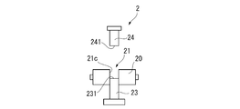
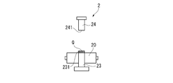
- the compression molding die 2 includes a main body 20, a first punch 23, and a second punch 24 provided to face the first punch 23.
- the main body 20 is replaceably attached to a substantially central portion of the middle movable plate 14. As shown in FIG. 1, the main body 20 has a through hole 21 that penetrates vertically.
- the first punch 23 and the second punch 24 are inserted into the through-hole 21 to form a molding chamber 22 for filling the organic EL element material into the compression mold 2.
- the molding chamber 22 has the shape of a compression molded body to be molded.
- the shape of the molding chamber 22, that is, the shape of the compression molded body may be a columnar shape or an elliptical column shape, and the cross section is a polygon such as a semicircular shape, a sector shape, a triangle shape, or a square shape, or an oval shape. It may be.
- the compression molded body may be a solid body or a hollow body.
- the first punch 23 and the second punch 24 pressurize and compress the organic EL element material filled in the molding chamber 22 from opposite directions.
- the first punch 23 and the second punch 24 are provided to be insertable into the through hole 21.
- the first punch 23 is fixed to the upper surface of the lower movable plate 13.
- the first punch 23 is configured to move in the axial direction of the through hole 21 when the lower movable plate 13 moves in the vertical direction.
- the first punch 23 is inserted from the other through hole inlet 21 b of the through hole 21.
- the second punch 24 is fixed to the lower surface of the upper movable plate 15.
- the second punch 24 is configured to move in the axial direction of the through hole 21 when the upper movable plate 15 moves in the vertical direction.
- the second punch 24 is inserted from one through hole inlet 21 a of the through hole 21.
- the first punch 23 and the second punch 24 are preferably formed slightly smaller than the through hole 21.
- a gap is formed between the side surface of the inserted first punch 23 and the inner peripheral surface 21 c of the through hole 21, and between the side surface of the second punch 24 and the inner peripheral surface 21 c of the through hole 21. It is preferable that the gas deaerated from the powder material inside is discharged through the gap.
- a first pressurizing surface 231 and a second pressurizing surface 241 for pressurizing the organic EL element material are provided at the respective end portions of the first punch 23 and the second punch 24.
- the first pressure surface 231 of the first punch 23 and the second pressure surface 241 of the second punch 24 are flat surfaces.
- a molding chamber 22 is formed by the first pressure surface 231 of the first punch 23, the second pressure surface 241 of the second punch 24, and the inner peripheral surface 21 c of the through hole 21 of the main body 20.
- the molding chamber 22 is filled with the organic EL element material, and is compressed between the first pressure surface 231 and the second pressure surface 241 by being pressed from above and below with the first punch 23 and the second punch 24. A molded body is obtained.
- FIG. 2 is a schematic cross-sectional view showing an enlarged part of the first punch 23 as a part of the surface of the compression mold 2 according to the present embodiment.
- the 1st pressurization surface 231 of the 1st punch 23 is a metal surface which contacts an organic EL element material at the time of pressurization and compression.
- a nitride film 25 containing nitride is stacked on the first pressure surface 231.
- a fluoride film 26 containing fluoride is laminated on the nitride film 25.
- the second pressure surface 241 of the second punch 24 and the inner peripheral surface 21c of the through hole 21 of the main body 20 are also metal surfaces that come into contact with the organic EL element material during pressure and compression.
- the nitride film 25 and the fluoride film 26 are laminated on the second pressure surface 241 and the inner peripheral surface 21c.
- the fluoride film 26 laminated on the first pressure surface 231, the second pressure surface 241, and the inner peripheral surface 21 c is formed by a dipping method.
- the nitride film 25 is made of a nitride selected from the group consisting of titanium aluminum nitride, titanium nitride carbide, chromium nitride, titanium nitride, titanium nitride silicon, and titanium aluminum nitride.
- it is made of titanium nitride aluminum.
- the nitride film 25 is made of titanium nitride aluminum formed by physical vapor deposition.
- the fluoride film 26 is preferably composed of a fluorocarbon compound.
- the fluorocarbon-based compound is composed of a chain portion formed of fluorocarbon and a reactive group that binds to another substance.
- Examples of the fluorocarbon-based compound include perfluoroalkyl silanes and perfluoropolyether group-containing silane compounds.
- Examples of perfluoroalkylsilanes include compounds represented by the following formula (1) and formula (2).
- n is 1, 3, 5, or 7, m is 2 or 3, and Me is a methyl group or an ethyl group.
- n is 1, 3, 5, or 7, m is 2 or 3, and R is a halogen element.
- Specific examples of the compound represented by the formula (1) or the formula (2) include CF 3 (CF 2 ) 5 CH 2 CH 2 Si (OCH 3 ) 3 (for example, TSL8257 manufactured by Momentive Performance Materials).
- CF 3 (CF 2 ) 7 CH 2 CH 2 Si (OCH 3 ) 3 for example, TSL8233 manufactured by Momentive Performance Materials
- CF 3 (CF 2 ) 7 CH 2 CH 2 Si (OCH 3 ) 2 for example, TSL8231 manufactured by Momentive Performance Materials, or KBM7803 manufactured by Shin-Etsu Chemical Co., Ltd.
- CF 3 (CF 2 ) 7 CH 2 CH 2 Si (OC 2 H 5 ) 3 for example, manufactured by Toray Dow Corning AY43-158E
- the perfluoropolyether group-containing silane compounds include perfluoropolyether-modified aminosilane and perfluoropolyether-modified polysilazane. Specifically, for example, KY-164 manufactured by Shin-Etsu Chemical Co., Ltd., OPTOOL series manufactured by Daikin Industries, and the like can be mentioned.
- the fluoride film 26 is not particularly limited as long as it is formed by an immersion method.
- the compression mold 2 is immersed in a fluoride-containing solution containing a fluorocarbon-based compound, and after the immersion, the fluoride-containing solution It is formed by drying.
- the 1st punch 23, the 2nd punch 24, and the main body 20 are immersed in a fluoride containing solution.
- at least the first pressure surface 231, the second pressure surface 241, and the inner peripheral surface 21 c are immersed in a fluoride-containing solution and dried to form the fluoride film 26 on each surface.
- the center line average roughness Ra of the 1st pressurization surface 231, the 2nd pressurization surface 241, and the internal peripheral surface 21c is 0.5 micrometer or less, and it is 0.1 micrometer or less. More preferred.
- the fluoride film 26 is present on the surface layer of each surface, if the center line average roughness Ra on the surface of the fluoride film 26 is 0.5 ⁇ m or less, the material for the organic EL element is formed after compression molding. It becomes difficult to adhere to these surfaces, and peeling from the compression molded body is suppressed.
- the compression molding apparatus 1 preferably has deaeration means for discharging gas from the inside of the molding chamber 22 to the outside, and at least one of the main body 20, the first punch 23, and the second punch 24 of the compression molding die 2 is It is preferable to have a deaeration means.
- the first punch 23 has a vibration device (not shown) as deaeration means. The first punch 23 is inserted from the through hole inlet 21 b of the through hole 21, and the recess formed by the inner peripheral surface 21 c of the through hole 21 and the first pressurizing surface 231 of the first punch 23 is filled with the powder material. After the filling, the first punch 23 is vibrated by the vibration device, so that the powder material in the filled state is degassed and discharged to the outside of the molding chamber 22.
- nitride film 25 by coating nitride on the metal surface of the compression mold 2 that comes into contact with the organic EL element material during pressurization and compression is performed.
- the nitride film 25 is formed on at least the first pressure surface 231, the second pressure surface 241, and the inner peripheral surface 21 c.
- the nitride film 25 is formed by coating each surface with nitride.
- the nitride film 25 can be formed by, for example, a physical vapor deposition (PVD) method, a chemical vapor deposition (CVD) method, or the like.
- the cleaning treatment include surface polishing treatment, ultrasonic cleaning treatment performed by immersing in an organic solvent, bombardment treatment with argon ions, and the like, and these treatments may be performed in combination.
- the first punch 23, the second punch 24, and the main body 20 are immersed in a fluoride-containing solution.
- at least the first pressure surface 231, the second pressure surface 241, and the inner peripheral surface 21 c on which the nitride film 25 is formed are immersed in the fluoride-containing solution.
- the fluoride-containing solution is dried to form a fluoride film 26 on each surface.
- the fluoride-containing solution may be dried at room temperature or may be dried by heating.
- the fluoride-containing solution includes a fluoride and a solvent.
- the fluoride is preferably composed of the above-mentioned fluorocarbon compound.
- the solvent is not particularly limited as long as it can dissolve fluoride, but an organic solvent is preferable.
- the organic solvent include aromatic hydrocarbon solvents such as toluene and xylene, ester solvents such as ethyl acetate and butyl acetate, ether solvents such as dioxane and diethyl ether, alcohol solvents such as butyl alcohol, methyl ethyl ketone, Examples thereof include ketone solvents such as methyl isobutyl ketone.
- the solvent may be a single type of solvent or a mixed solvent in which a plurality of types are mixed.
- the fluoride-containing solution it is preferable to remove the solvent and chemically bond the fluoride to the nitride film 25 to form the fluoride film 26.
- the fluoride is chemically bonded to the nitride film 25, it is preferable that the nitride film 25 is activated in advance. The activation process is performed on the surface of the nitride film 25 by the activation process to form an activation layer. Fluoride is preferably chemically bonded to the activation layer formed on the surface of the nitride film 25.
- the dirt adhering to the surface of the nitride film 25 is decomposed and cleaned, and an activation layer having molecular bonds is formed on the surface of the nitride film. Then, a hydroxyl group is adsorbed on this molecular bond, and reacts with a reactive group of the fluorocarbon compound to facilitate the bonding.
- the activation treatment is not particularly limited, and examples of the physical method include corona discharge treatment, plasma treatment, ultraviolet irradiation treatment, and flame treatment.
- Examples of the chemical method include a treatment of immersing in an acid or alkali solution, an oxidant treatment, an ozone treatment, and the like.
- corona discharge treatment, plasma treatment, ultraviolet irradiation treatment, and ozone treatment are preferable because damage to the surface of the nitride film 25 can be prevented, and plasma treatment and ultraviolet irradiation treatment are preferable.
- the efficiency of activating the surface is high and further preferable.
- the fluoride film 26 After forming the fluoride film 26, it is preferable to carry out a step of removing unreacted fluoride.
- the surface of the fluoride film 26, that is, the surface in contact with the organic EL element material can be cleaned.
- the method for removing the fluoride is not particularly limited, but the fluoride film 26 is preferably washed with a solvent, and more preferably washed with the same type of solvent as that used for the fluoride-containing solution.
- a laminated film including the nitride film 25 and the fluoride film 26 is formed on the first punch 23, the second punch 24, and the main body 20 of the compression mold 2.
- 3A to 3E show the main body 20, the first punch 23, and the second punch 24 of the compression molding die 2 in each step of the manufacturing method of the compression molded body, and other configurations are omitted.
- the manufacturing method of the compression molding body of this embodiment implemented using the compression molding die 2 is a method of filling an organic EL element material and molding it with a pressing force along a single axis.
- the first punch 23 is inserted with the first pressure surface 231 facing the inside of the through hole 21.
- the first pressure surface 231 is inserted until it reaches a position having a predetermined depth in the through hole 21. This depth dimension is set by the thickness dimension of the compression molded body.
- the powdery organic EL element material P is filled into the through hole 21 whose bottom surface is formed by the first pressure surface 231.
- the first punch 23 is vibrated by the above-described vibration device to perform a deaeration process.
- the second pressurization surface 241 faces the inside of the through hole 21, the second punch 24 is inserted, and the first pressurization surface 231 of the first punch 23 is opposed to the first pressurization surface 231.
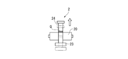
- the molding chamber 22 is formed by the inner peripheral surface 21 c of the hole 21, the first pressure surface 231, and the second pressure surface 241.
- the compression molded body Q is formed by compressing the organic EL element material P between the first pressure surface 231 and the second pressure surface 241.
- the compression pressure is preferably 11 MPa or more.
- the surface temperatures of the inner peripheral surface 21c of the main body 20, the first pressure surface 231 of the first punch 23, and the second pressure surface 241 of the second punch 24 are preferably 10 ° C. or higher.
- the first punch 23 and the first punch 23 and the second pressurization surface 241 of the second punch 24 are sandwiched between the first pressurization surface 231 and the second pressurization surface 241 of the second punch 24.
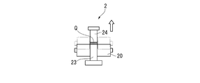
- the second punch 24 is moved upward to extract the compression molded body Q from the through hole 21.
- the upward movement of the first punch 23 and the second punch 24 is preferably stopped when the first pressure surface 231 of the first punch 23 coincides with the upper surface of the main body 20.
- the first punch 23 and the second punch 24 are preferably moved upward at a low speed so that the stress acting on the compression molded body Q is not released at a stretch.
- the second punch 24 is moved upward to open the upper surface of the compression molded body Q. Thereafter, the compression molded body Q placed on the first pressure surface 231 is taken out.
- the manufacturing method of an organic EL element using the compression molding body Q obtained by compressing the material for organic EL elements.
- the organic EL element material of the present embodiment is not mixed with a molding aid such as a binder or a lubricant.
- the material for the organic EL device is a material used for the organic EL device and is not particularly limited.
- a hole transporting material used for the hole transport layer a host material used for the light emitting layer, a dopant material, an electron transport. Examples thereof include an electron transporting material used for the layer.
- the organic EL element material may be configured by mixing a plurality of types of organic EL element materials.
- the one where the average particle diameter D50 (median diameter) of the organic EL element material P before molding is preferably smaller.
- the average particle diameter D50 of the organic EL element material P is preferably 70 ⁇ m or less, more preferably 45 ⁇ m or less, and even more preferably 30 ⁇ m or less.
- the difference between the maximum particle size and the minimum particle size is small.
- the average particle diameter D50 of the organic EL element material P satisfies the above-described preferable range.
- the molding chamber 22 filled with the organic EL element material P is the first pressurizing surface 231 of the first punch 23 and the second punch 24.
- the second pressure surface 241 and the inner peripheral surface 21c of the through hole 21 of the main body 20 are formed.
- a nitride film 25 and a fluoride film 26 are stacked on the first pressure surface 231, the second pressure surface 241, and the inner peripheral surface 21c.
- the fluoride film 26 is formed by an immersion method.
- the fluoride film 26 is uniformly formed on the first pressure surface 231, the second pressure surface 241, and the inner peripheral surface 21c by the dipping method.
- a fluoride-containing solution is applied by a coating method such as brush coating, and a fluoride film is formed by heating and drying.
- a fluoride film is formed by heating and drying.
- it is difficult to form a fluoride film uniformly, and organic
- the EL element material easily adheres to the mold surface, and the surface of the compression molded body becomes rough.
- the amount of the material partially peeled from the compression molded body or the amount of powder scattered from the surface of the molded body increases, and the weight of the compression molded body after molding is reduced by 10% or more. It is remarkable.
- the first punch 23 is vibrated by the above-described vibration device, and deaeration treatment is performed, so that the organic EL element material P is contained in the filled organic EL element material P.
- the gas that had been removed can be removed.
- the compression pressure at the time of compressing the organic EL element material P between the 1st pressurization surface 231 and the 2nd pressurization surface 241 is 11 Mpa or more. As a result, the particles of the organic EL element material P are more closely packed, and it is possible to prevent the material from partially peeling from the compression molded body Q after compression molding and the powder scattering from the surface of the molded body. .
- the organic EL element material that does not contain a molding aid has been described as an example.
- the compression molded body in which peeling after molding has occurred does not have sufficient hardness.
- the material is partially peeled from the compression molding Q or the surface of the molding The powder can be prevented from being scattered. Therefore, the frequency
- the wear resistance of the fluoride film 26 is improved. Can be improved.
- the laminated film laminated on the metal surface of the compression mold 2 is not limited to the configuration of the above embodiment.
- a layer different from the above-described activation layer may be interposed between the nitride film 25 and the fluoride film 26, or the formation of the activation layer may be omitted and the nitride film 25 and the fluoride film 26 directly. It is good also as a laminated film of the 2 layer structure which laminated
- the deaeration means provided in the compression molding apparatus 1 is not limited to the vibration device, and may be, for example, an ultrasonic generator, a tapping device, or a vacuum deaeration device. As a deaeration means, what is necessary is just to be able to deaerate from the powder material with which the molding chamber 22 was filled. Further, the deaeration means is not limited to being provided in the first punch 23, and may be provided in the second punch 24 or the main body 20.
- the through-hole inlet 21a of the through-hole 21 of the compression mold 2 may be tapered.
- the taper processing is performed so that the hole diameter increases from the inside of the through hole 21 toward the through hole inlet 21a. It is preferable that a laminated film of the nitride film 25 and the fluoride film 26 is also formed in this tapered portion. Note that the through hole inlet 21b may also be tapered.
- the method of extracting the compression molding body Q from the compression molding die 2 is not limited to the method demonstrated by the said embodiment.
- the main body 20 is moved downward.
- the downward movement of the main body 20 is preferably stopped when the upper surface of the main body 20 coincides with the first pressure surface 231 of the first punch 23.
- the main body 20 is preferably moved downward at a low speed so that the stress acting on the compression molded body Q is not released at a stretch.
- the second punch 24 is moved upward to open the upper surface of the compression molded body Q. Thereafter, the compression molded body Q placed on the first pressure surface 231 is taken out.
- compression molding is not limited to the method described in the above embodiment.
- compression molding may be performed by a floating die method.
- the floating die method pressure is applied by the second punch 24, and the frictional force gradually increases between the inner peripheral surface 21 c of the through hole 21 of the main body 20 and the organic EL element material, and is larger than the supporting force of the main body 20.
- the main body 20 descends together with the middle movable plate 14.
- the first punch 23 is relatively raised.
- the 2nd punch 24 is raised and a compression molding body is taken out. According to such a floating die system, it is possible to adjust the density in the thickness direction of the compression molded body.
- a withdrawing method, a one-pushing method in which only the second punch 24 is lowered, or the like can be employed. Even when these methods are employed, the nitride film 25 is formed on the first pressure surface 231 of the first punch 23, the second pressure surface 241 of the second punch 24, and the inner peripheral surface 21 c of the through hole 21 of the main body 20.
- the laminated film of the fluoride film 26 it is possible to prevent the material from partially peeling from the compression molded body Q after the compression molding or the powder from being scattered from the surface of the molded body.
- the compression mold is not limited to the mechanism or shape described in the above embodiment, and may be a mold having a mechanism and shape that can form a compression molded body by pressurizing and compressing a powdery material. That's fine.
- SYMBOLS 1 ... Compression molding apparatus, 2 ... Compression molding die, 21 ... Through-hole, 21a, 21b ... Through-hole inlet, 21c ... Inner peripheral surface, 22 ... Molding chamber, 23 ... 1st punch, 231 ... 1st pressurization surface, 24 ... 2nd punch, 241 ... 2nd pressurization surface, P ... Powder material, Q ... Compression molding.
Abstract
Description
また、近年は、電子デバイス等に用いられる有機材料の粉末材料を圧縮成形する方法が検討されている。このような有機電子材料素子の一対の電極間に設けられる有機層は、一般的に真空加熱蒸着することで形成される。蒸着源に入れる有機素子用材料は一般的に粉末状であるが、粉末状であると、充填効率が低く、またハンドリング性に劣り、粉末が飛散したりする問題が生じていたからである。 Conventionally, a method has been adopted in which a powder material is filled in a molding chamber of a compression molding die and is compressed by a punch.
In recent years, methods for compression molding organic powder materials used in electronic devices and the like have been studied. The organic layer provided between a pair of electrodes of such an organic electronic material element is generally formed by vacuum heating vapor deposition. This is because the organic element material to be put into the vapor deposition source is generally in the form of powder, but if it is in the form of powder, the filling efficiency is low, the handling property is inferior, and the powder is scattered.
(1)圧縮成形装置の構成
図1には、本実施形態に係る圧縮成形装置1の概略図が示されている。
本実施形態では、有機EL素子用材料を加圧および圧縮して圧縮成形体を製造する。
圧縮成形装置1は、圧縮成形金型2と、ベース部10と、ベース部10に互いに平行に立設された2本のガイドバー11と、ガイドバー11の上端に連結された上部フレーム12と、ベース部10および上部フレーム12の間にて支持されている下部可動板13、中部可動板14および上部可動板15とを備える。図1に示すように、下部可動板13、中部可動板14および上部可動板15は、ベース部10側からこの順に互いに平行に設けられている。また、下部可動板13、中部可動板14および上部可動板15は、ガイドバー11に沿って上下方向にそれぞれ独立に移動可能に設けられている。なお、下部可動板13、中部可動板14および上部可動板15は、図示しない油圧シリンダ等の液体圧式駆動機構、エアシリンダ等の空気圧式駆動機構、あるいはカムもしくはクランク機構等の機械式駆動機構により移動できるように構成されている。 <First embodiment>
(1) Configuration of Compression Molding Apparatus FIG. 1 shows a schematic diagram of a compression molding apparatus 1 according to the present embodiment.
In this embodiment, a compression molded body is manufactured by pressurizing and compressing an organic EL element material.
The compression molding apparatus 1 includes a
第1パンチ23は、下部可動板13の上面に固定されている。第1パンチ23は、下部可動板13が上下方向に移動することで、貫通孔21の軸方向に移動するように構成されている。第1パンチ23は、貫通孔21の他方の貫通孔入口21bから挿入される。第2パンチ24は、上部可動板15の下面に固定されている。第2パンチ24は、上部可動板15が上下方向に移動することで、貫通孔21の軸方向に移動するように構成されている。第2パンチ24は、貫通孔21の一方の貫通孔入口21aから挿入される。第1パンチ23および第2パンチ24は、貫通孔21よりも若干小さく形成されていることが好ましい。挿入された第1パンチ23の側面と貫通孔21の内周面21cとの間、並びに第2パンチ24の側面と貫通孔21の内周面21cとの間に隙間が形成され、成形室22内の粉末材料から脱気された気体が、当該隙間を通過して排出されることが好ましい。
第1パンチ23および第2パンチ24のそれぞれの端部には、有機EL素子用材料を加圧する第1加圧面231および第2加圧面241が設けられている。本実施形態では、第1パンチ23の第1加圧面231および第2パンチ24の第2加圧面241は、平坦な面である。第1パンチ23の第1加圧面231と、第2パンチ24の第2加圧面241と、本体20の貫通孔21の内周面21cとで、成形室22が形成される。成形室22に有機EL素子用材料が充填され、第1パンチ23および第2パンチ24で上下方向から加圧することで、第1加圧面231と第2加圧面241との間で圧縮されて圧縮成形体が得られる。 The
The
A first pressurizing
第1パンチ23の第1加圧面231は、加圧および圧縮時に有機EL素子用材料と接触する金属面である。図2に示すように、第1加圧面231には、窒化物を含む窒化物膜25が積層されている。さらに、窒化物膜25の上には、フッ化物を含むフッ化物膜26が積層されている。
第2パンチ24の第2加圧面241、および本体20の貫通孔21の内周面21cも、加圧および圧縮時に有機EL素子用材料と接触する金属面である。第2加圧面241、および内周面21cにも、第1加圧面231と同様に、窒化物膜25およびフッ化物膜26が積層されている。本実施形態では、第1加圧面231、第2加圧面241、および内周面21cに積層されたフッ化物膜26は、浸漬法によって形成されている。 FIG. 2 is a schematic cross-sectional view showing an enlarged part of the
The
The
パーフルオロアルキルシラン類としては、下記式(1)や式(2)で表される化合物が挙げられる。
CF3(CF2)nCH2CH2Si(OMe)m …(1)
CF3(CF2)nCH2CH2Si(OR)m …(2)
ただし、前記式(1)において、nは、1,3,5,または7であり、mは、2または3であり、Meは、メチル基またはエチル基である。
また、前記式(2)において、nは、1,3,5,または7であり、mは、2または3であり、Rは、ハロゲン元素である。
前記式(1)や式(2)で表される化合物の具体例としては、CF3(CF2)5CH2CH2Si(OCH3)3(例えば、モメンティブ・パフォーマンス・マテリアルズ製のTSL8257)、CF3(CF2)7CH2CH2Si(OCH3)3(例えば、モメンティブ・パフォーマンス・マテリアルズ製のTSL8233)、CF3(CF2)7CH2CH2Si(OCH3)2(例えば、モメンティブ・パフォーマンス・マテリアルズ製のTSL8231、または信越化学工業製のKBM7803)、CF3(CF2)7CH2CH2Si(OC2H5)3(例えば、東レ・ダウコーニング製のAY43-158E)などが挙げられる。
パーフルオロポリエーテル基含有シラン化合物類には、パーフルオロポリエーテル変性アミノシラン、パーフルオロポリエーテル変性ポリシラザンなどがある。具体的には、例えば、信越化学工業製のKY-164、ダイキン工業製のオプツールシリーズなどが挙げられる。 The
Examples of perfluoroalkylsilanes include compounds represented by the following formula (1) and formula (2).
CF 3 (CF 2 ) n CH 2 CH 2 Si (OMe) m (1)
CF 3 (CF 2 ) n CH 2 CH 2 Si (OR) m (2)
However, in said formula (1), n is 1, 3, 5, or 7, m is 2 or 3, and Me is a methyl group or an ethyl group.
In the formula (2), n is 1, 3, 5, or 7, m is 2 or 3, and R is a halogen element.
Specific examples of the compound represented by the formula (1) or the formula (2) include CF 3 (CF 2 ) 5 CH 2 CH 2 Si (OCH 3 ) 3 (for example, TSL8257 manufactured by Momentive Performance Materials). ), CF 3 (CF 2 ) 7 CH 2 CH 2 Si (OCH 3 ) 3 (for example, TSL8233 manufactured by Momentive Performance Materials), CF 3 (CF 2 ) 7 CH 2 CH 2 Si (OCH 3 ) 2 (For example, TSL8231 manufactured by Momentive Performance Materials, or KBM7803 manufactured by Shin-Etsu Chemical Co., Ltd.), CF 3 (CF 2 ) 7 CH 2 CH 2 Si (OC 2 H 5 ) 3 (for example, manufactured by Toray Dow Corning AY43-158E) and the like.
Examples of the perfluoropolyether group-containing silane compounds include perfluoropolyether-modified aminosilane and perfluoropolyether-modified polysilazane. Specifically, for example, KY-164 manufactured by Shin-Etsu Chemical Co., Ltd., OPTOOL series manufactured by Daikin Industries, and the like can be mentioned.
次に、圧縮成形金型2の製造方法について説明する。
まず、加圧および圧縮時に有機EL素子用材料と接触する圧縮成形金型2の金属面に、窒化物をコーティングして窒化物膜25を形成する工程を実施する。本実施形態では、少なくとも、第1加圧面231、第2加圧面241、および内周面21cに窒化物膜25を形成する。窒化物膜25は、窒化物を各面にコーティングすることで形成される。窒化物膜25は、例えば、物理気相蒸着(Physical Vapor Deposition,PVD)法や化学気相蒸着(Chemical Vapor Deposition,CVD)法などによって形成することができる。窒化物膜25の形成前には、第1パンチ23の表面、第2パンチ24の表面、並びに本体20の表面および内周面21cを清浄化しておくことが好ましい。清浄化処理としては、例えば、表面研磨処理、有機溶媒等に浸漬させて行う超音波洗浄処理、アルゴンイオン等によるボンバード処理などが挙げられ、これらの処理を組み合わせて実施してもよい。 (2) Manufacturing method of compression molding die Next, the manufacturing method of the compression molding die 2 is demonstrated.
First, a step of forming a
フッ化物含有溶液を乾燥させる際に、溶媒を除去するとともに、フッ化物を窒化物膜25に化学結合させてフッ化物膜26を形成することが好ましい。窒化物膜25にフッ化物を化学結合させる際には、予め窒化物膜25に活性化処理を施しておくことが好ましい。活性化処理によって窒化物膜25の表面に活性化処理を施して活性化層が形成される。この窒化物膜25の表面に形成された活性化層に対して、フッ化物を化学結合させることが好ましい。活性化層を形成するための活性化処理を行うことで、窒化物膜25の表面に付着した汚れが分解されて清浄化され、窒化物膜表面には分子結合手を有する活性化層が形成され、この分子結合手に水酸基が吸着し、フッ化炭素系化合物の反応基と反応して結合し易くなる。 In the present embodiment, the fluoride-containing solution includes a fluoride and a solvent. The fluoride is preferably composed of the above-mentioned fluorocarbon compound. The solvent is not particularly limited as long as it can dissolve fluoride, but an organic solvent is preferable. Examples of the organic solvent include aromatic hydrocarbon solvents such as toluene and xylene, ester solvents such as ethyl acetate and butyl acetate, ether solvents such as dioxane and diethyl ether, alcohol solvents such as butyl alcohol, methyl ethyl ketone, Examples thereof include ketone solvents such as methyl isobutyl ketone. The solvent may be a single type of solvent or a mixed solvent in which a plurality of types are mixed.
When drying the fluoride-containing solution, it is preferable to remove the solvent and chemically bond the fluoride to the
次に、圧縮成形装置1、および圧縮成形金型2を用いて実施する圧縮成形体の製造方法について説明する。
図3A~図3Eには、圧縮成形体の製造方法の各工程における圧縮成形金型2の本体20、第1パンチ23および第2パンチ24について記載され、その他の構成は省略されている。圧縮成形金型2を用いて実施する本実施形態の圧縮成形体の製造方法は、有機EL素子用材料を充填し、単軸に沿った加圧力で成形する方法である。 (3) Manufacturing method of compression molding Next, the manufacturing method of the compression molding implemented using the compression molding apparatus 1 and the compression molding die 2 is demonstrated.
3A to 3E show the
圧縮圧力は、11MPa以上であることが好ましい。また、本体20の内周面21c、第1パンチ23の第1加圧面231、および第2パンチ24の第2加圧面241の表面温度が、10℃以上であることが好ましい。 Next, as shown in FIG. 3C, the
The compression pressure is preferably 11 MPa or more. Further, the surface temperatures of the inner
なお、有機EL素子用材料Pの平均粒径D50が、上述の好ましい範囲を満たしていることが本実施形態において好適である。 In this embodiment, the one where the average particle diameter D50 (median diameter) of the organic EL element material P before molding is preferably smaller. As the average particle diameter D50 of the organic EL element material P becomes smaller, the hardness of the compression molded body can be improved. The average particle diameter D50 of the organic EL element material P is preferably 70 μm or less, more preferably 45 μm or less, and even more preferably 30 μm or less. In the particle size distribution of the organic EL element material P, it is preferable that the difference between the maximum particle size and the minimum particle size is small.
In the present embodiment, it is preferable that the average particle diameter D50 of the organic EL element material P satisfies the above-described preferable range.
本実施形態に係る圧縮成形金型2では、有機EL素子用材料Pが充填される成形室22は、第1パンチ23の第1加圧面231、第2パンチ24の第2加圧面241、および本体20の貫通孔21の内周面21cとで形成される。第1加圧面231、第2加圧面241、および内周面21cには、窒化物膜25およびフッ化物膜26が積層されている。フッ化物膜26は、浸漬法によって形成されている。その結果、圧縮成形後に圧縮成形体Qから材料が部分的に剥離したり、成形体表面から粉末が飛散したりすることを抑制できる。また、圧縮成形体Qの表面を滑らかに成形することができる。浸漬法によってフッ化物膜26が第1加圧面231、第2加圧面241、および内周面21cに均一形成されているためと考えられる。
なお、従来、刷毛塗り等の塗布法でフッ化物含有溶液を塗布し、加熱乾燥にてフッ化物膜を形成しているが、このような方法では、フッ化物膜が均一に形成され難く、有機EL素子用材料が金型表面に付着し易く、圧縮成形体の表面は、荒れてしまう。その結果、圧縮成形体から材料が部分的に剥離したり、成形体表面から粉末が飛散したりする量が増えてしまい、成形後の圧縮成形体の重量が10%以上減少し、重量減少が著しい。 (3) Effects of this Embodiment In the compression molding die 2 according to this embodiment, the
Conventionally, a fluoride-containing solution is applied by a coating method such as brush coating, and a fluoride film is formed by heating and drying. However, in such a method, it is difficult to form a fluoride film uniformly, and organic The EL element material easily adheres to the mold surface, and the surface of the compression molded body becomes rough. As a result, the amount of the material partially peeled from the compression molded body or the amount of powder scattered from the surface of the molded body increases, and the weight of the compression molded body after molding is reduced by 10% or more. It is remarkable.
なお、本発明は、上述した実施形態に限定されるものではなく、本発明の目的を達成できる範囲で、以下に示される変形等をも含む。 <Modification>
In addition, this invention is not limited to embodiment mentioned above, In the range which can achieve the objective of this invention, the deformation | transformation etc. which are shown below are included.
例えば、図4Aに示すように、本体20を下降移動させる。図4Bに示すように、本体20の下降移動は、本体20の上面が、第1パンチ23の第1加圧面231と一致したところで停止することが好ましい。本体20は、圧縮成形体Qに作用している応力が一気に解放されないよう、低速度で下降移動させることが好ましい。次に、図4Cに示すように、第2パンチ24を上昇移動させて、圧縮成形体Qの上面を開放する。その後、第1加圧面231上に載置されている圧縮成形体Qを取り出す。 In addition, the method of extracting the compression molding body Q from the compression molding die 2 is not limited to the method demonstrated by the said embodiment.
For example, as shown in FIG. 4A, the
Claims (13)
- 有機EL素子用材料を加圧および圧縮して圧縮成形体を成形するための圧縮成形金型であって、圧縮時に前記有機EL素子用材料と接触する圧縮成形金型の金属面には、窒化物を含む窒化物膜が積層され、前記窒化物膜には、浸漬法によって形成されたフッ化物を含むフッ化物膜が積層されている圧縮成形金型。 A compression mold for forming a compression molded body by pressurizing and compressing an organic EL element material, and the metal surface of the compression mold that comes into contact with the organic EL element material during compression is nitrided A compression molding die in which a nitride film containing a product is laminated, and a fluoride film containing a fluoride formed by an immersion method is laminated on the nitride film.
- 貫通孔を有する本体と、前記貫通孔の互いに異なる貫通孔入口からそれぞれ挿入され、前記本体の内部の成形室に充填された有機EL素子用材料を加圧するための加圧面がそれぞれ設けられている第1パンチ及び第2パンチと、を備え、前記加圧面に窒化物を含む窒化物膜および浸漬法によって形成されたフッ化物を含むフッ化物膜が積層されている圧縮成形金型。 A main body having a through-hole and a pressure surface for pressurizing the organic EL element material that is inserted from different through-hole inlets of the through-hole and filled in the molding chamber inside the main body are provided. A compression mold comprising: a first punch and a second punch, wherein a nitride film containing nitride and a fluoride film containing fluoride formed by a dipping method are laminated on the pressing surface.
- 請求項2に記載の圧縮成形金型において、前記貫通孔の内周面にも前記窒化物膜および前記フッ化物膜が積層されている圧縮成形金型。 3. The compression mold according to claim 2, wherein the nitride film and the fluoride film are also laminated on the inner peripheral surface of the through hole.
- 請求項1から請求項3のいずれか一項に記載の圧縮成形金型において、前記窒化物膜は、窒化チタンアルミ、窒化チタンカーバイド、窒化クロム、窒化チタン、窒化チタンシリコン、および窒化チタンアルミシリコンからなる群から選択される窒化物で構成される圧縮成形金型。 4. The compression mold according to claim 1, wherein the nitride film includes titanium aluminum nitride, titanium nitride carbide, chromium nitride, titanium nitride, titanium nitride silicon, and titanium nitride aluminum silicon. 5. A compression mold made of a nitride selected from the group consisting of:
- 請求項1から請求項4のいずれか一項に記載の圧縮成形金型において、前記フッ化物は、フッ化炭素系化合物である圧縮成形金型。 5. The compression molding die according to any one of claims 1 to 4, wherein the fluoride is a fluorocarbon-based compound.
- 有機EL素子用材料を加圧および圧縮して圧縮成形体を成形するための圧縮成形金型の製造方法であって、圧縮時に前記有機EL素子用材料と接触する圧縮成形金型の金属面に、窒化物膜を形成する工程と、前記窒化物膜が形成された面をフッ化物を含有するフッ化物含有溶液に浸漬する工程と、前記フッ化物含有溶液を乾燥させてフッ化物膜を形成する工程と、を有する圧縮成形金型の製造方法。 A method for manufacturing a compression mold for pressurizing and compressing an organic EL element material to form a compression molded body, wherein the compression molding mold is in contact with the organic EL element material during compression. A step of forming a nitride film, a step of immersing the surface on which the nitride film is formed in a fluoride-containing solution containing fluoride, and drying the fluoride-containing solution to form a fluoride film. And a method for producing a compression mold having the steps.
- 請求項6に記載の圧縮成形金型の製造方法において、前記フッ化物含有溶液は、前記フッ化物および溶媒を含み、前記フッ化物膜を形成する工程で、前記溶媒を除去するとともに、前記フッ化物を前記窒化物膜に化学結合させて前記フッ化物膜を形成し、前記フッ化物膜を形成した後に、未反応のフッ化物を除去する圧縮成形金型の製造方法。 7. The method of manufacturing a compression mold according to claim 6, wherein the fluoride-containing solution includes the fluoride and a solvent, and in the step of forming the fluoride film, the solvent is removed and the fluoride is included. Is formed by forming a fluoride film by chemically bonding the nitride film to the nitride film, and after forming the fluoride film, a non-reacted fluoride is removed.
- 請求項7に記載の圧縮成形金型の製造方法において、前記未反応のフッ化物を除去する際に、前記フッ化物含有溶液に含まれていた前記溶媒と同じ種類の溶媒で前記フッ化物膜を洗浄する圧縮成形金型の製造方法。 8. The method of manufacturing a compression mold according to claim 7, wherein when the unreacted fluoride is removed, the fluoride film is formed using the same type of solvent as the solvent contained in the fluoride-containing solution. A method for producing a compression mold for cleaning.
- 請求項6から請求項8のいずれか一項に記載の圧縮成形金型の製造方法において、前記窒化物膜に、コロナ放電処理、プラズマ処理、紫外線照射処理、フレーム処理、酸およびアルカリの少なくともいずれかの溶液に浸漬させる処理、酸化剤処理、並びにオゾン処理のうち少なくともいずれかの活性化処理を施した後で、前記窒化物膜が形成された面を前記フッ化物含有溶液に浸漬する圧縮成形金型の製造方法。 9. The method of manufacturing a compression mold according to claim 6, wherein the nitride film is provided with at least one of corona discharge treatment, plasma treatment, ultraviolet irradiation treatment, flame treatment, acid and alkali. Compression molding in which the surface on which the nitride film is formed is immersed in the fluoride-containing solution after at least one of activation treatment among immersion treatment, oxidant treatment, and ozone treatment is performed. Mold manufacturing method.
- 請求項9に記載の圧縮成形金型の製造方法において、前記活性化処理は、コロナ放電処理、プラズマ処理、紫外線照射処理、またはオゾン処理である圧縮成形金型の製造方法。 10. The method for manufacturing a compression mold according to claim 9, wherein the activation treatment is corona discharge treatment, plasma treatment, ultraviolet irradiation treatment, or ozone treatment.
- 請求項9に記載の圧縮成形金型の製造方法において、前記活性化処理は、プラズマ処理または紫外線照射処理である圧縮成形金型の製造方法。 10. The method for manufacturing a compression mold according to claim 9, wherein the activation process is a plasma process or an ultraviolet irradiation process.
- 有機EL素子用材料を加圧および圧縮して圧縮成形体を製造する圧縮成形体の製造方法であって、圧縮時に前記有機EL素子用材料と接触する圧縮成形金型の金属面には、窒化物を含む窒化物膜が積層され、前記窒化物膜には、浸漬法によって形成されたフッ化物を含むフッ化物膜が積層されている圧縮成形体の製造方法。 A method for producing a compression-molded body in which a compression-molded body is produced by pressurizing and compressing an organic EL element material, and a metal surface of a compression mold that comes into contact with the organic EL element material during compression is nitrided A method of manufacturing a compression molded body in which a nitride film containing a product is laminated, and a fluoride film containing a fluoride formed by an immersion method is laminated on the nitride film.
- 請求項12に記載の圧縮成形体の製造方法において、前記窒化物膜は、窒化チタンアルミ、窒化チタンカーバイド、窒化クロム、窒化チタン、窒化チタンシリコン、および窒化チタンアルミシリコンからなる群から選択される窒化物で構成される圧縮成形体の製造方法。 13. The method of manufacturing a compression molded body according to claim 12, wherein the nitride film is selected from the group consisting of titanium aluminum nitride, titanium nitride carbide, chromium nitride, titanium nitride, titanium nitride silicon, and titanium aluminum nitride. A method for producing a compression molded body made of nitride.
Priority Applications (2)
| Application Number | Priority Date | Filing Date | Title |
|---|---|---|---|
| CN201580001414.9A CN105408081B (en) | 2014-03-31 | 2015-03-19 | Compression molding die, method for manufacturing compression molding die, and method for manufacturing compression molded body |
| KR1020167001174A KR20160137938A (en) | 2014-03-31 | 2015-03-19 | Compression molding die, production method for compression molding die, and production method for compression-molded article |
Applications Claiming Priority (2)
| Application Number | Priority Date | Filing Date | Title |
|---|---|---|---|
| JP2014072910A JP6096147B2 (en) | 2014-03-31 | 2014-03-31 | Method for manufacturing compression mold and method for manufacturing compression molded body |
| JP2014-072910 | 2014-03-31 |
Publications (1)
| Publication Number | Publication Date |
|---|---|
| WO2015151825A1 true WO2015151825A1 (en) | 2015-10-08 |
Family
ID=54240156
Family Applications (1)
| Application Number | Title | Priority Date | Filing Date |
|---|---|---|---|
| PCT/JP2015/058182 WO2015151825A1 (en) | 2014-03-31 | 2015-03-19 | Compression molding die, production method for compression molding die, and production method for compression-molded article |
Country Status (4)
| Country | Link |
|---|---|
| JP (1) | JP6096147B2 (en) |
| KR (1) | KR20160137938A (en) |
| CN (1) | CN105408081B (en) |
| WO (1) | WO2015151825A1 (en) |
Cited By (1)
| Publication number | Priority date | Publication date | Assignee | Title |
|---|---|---|---|---|
| JP2020514060A (en) * | 2016-12-22 | 2020-05-21 | ゲーカーエン シンター メタルズ エンジニアリング ゲーエムベーハー | Mold for press machine |
Citations (8)
| Publication number | Priority date | Publication date | Assignee | Title |
|---|---|---|---|---|
| JPH03216298A (en) * | 1990-01-19 | 1991-09-24 | Idemitsu Kosan Co Ltd | Compression molding method |
| JPH03254910A (en) * | 1989-07-11 | 1991-11-13 | Hitachi Tool Eng Ltd | Die for molding plastic |
| JPH03272815A (en) * | 1990-02-27 | 1991-12-04 | Nippon Tungsten Co Ltd | Mold for molding resin material |
| JP2000061952A (en) * | 1998-08-21 | 2000-02-29 | Sumitomo Electric Ind Ltd | Member for resin molding device and manufacture thereof |
| JP2002001733A (en) * | 2000-06-26 | 2002-01-08 | Fuji Dies Kk | Mold for molding tablet of resin for sealing semiconductor |
| JP2004273456A (en) * | 2003-03-07 | 2004-09-30 | Eastman Kodak Co | Method of forming solid compacted pellet of organic material and method of manufacturing oled display |
| JP2008112977A (en) * | 2006-10-06 | 2008-05-15 | Hitachi Chem Co Ltd | Tablet molding die, tablet, manufacturing method for optical semiconductor element-mounting substrate and optical semiconductor device |
| JP2012056246A (en) * | 2010-09-10 | 2012-03-22 | Fujifilm Corp | Ni MASTER HAVING FINE UNEVEN PATTERN ON SURFACE AND METHOD OF MANUFACTURING Ni REPLICATION USING THE SAME |
Family Cites Families (8)
| Publication number | Priority date | Publication date | Assignee | Title |
|---|---|---|---|---|
| JPH0649295B2 (en) | 1989-02-01 | 1994-06-29 | チッソ株式会社 | Release agent for powder molding and method of manufacturing molded article using the same |
| US7153592B2 (en) * | 2000-08-31 | 2006-12-26 | Fujitsu Limited | Organic EL element and method of manufacturing the same, organic EL display device using the element, organic EL material, and surface emission device and liquid crystal display device using the material |
| JP3292199B2 (en) * | 2001-03-22 | 2002-06-17 | 住友電気工業株式会社 | Rubber mold, method for manufacturing rubber mold, and method for molding rubber |
| JP4582497B2 (en) * | 2004-02-27 | 2010-11-17 | 株式会社ダイヤメット | Molding method of powder compact |
| JP5516653B2 (en) * | 2006-10-06 | 2014-06-11 | 日立化成株式会社 | Tablet molding die, tablet, optical semiconductor element mounting substrate manufacturing method, and optical semiconductor device. |
| KR100949819B1 (en) | 2008-03-11 | 2010-03-30 | 박진연 | Die assembly for tablet |
| JP3163163U (en) | 2010-07-21 | 2010-09-30 | 株式会社ジェピア | Mold |
| JP5725339B2 (en) * | 2011-03-25 | 2015-05-27 | 株式会社小糸製作所 | Hot plate welding jig and manufacturing method thereof, metal member |
-
2014
- 2014-03-31 JP JP2014072910A patent/JP6096147B2/en not_active Expired - Fee Related
-
2015
- 2015-03-19 KR KR1020167001174A patent/KR20160137938A/en not_active Application Discontinuation
- 2015-03-19 WO PCT/JP2015/058182 patent/WO2015151825A1/en active Application Filing
- 2015-03-19 CN CN201580001414.9A patent/CN105408081B/en not_active Expired - Fee Related
Patent Citations (8)
| Publication number | Priority date | Publication date | Assignee | Title |
|---|---|---|---|---|
| JPH03254910A (en) * | 1989-07-11 | 1991-11-13 | Hitachi Tool Eng Ltd | Die for molding plastic |
| JPH03216298A (en) * | 1990-01-19 | 1991-09-24 | Idemitsu Kosan Co Ltd | Compression molding method |
| JPH03272815A (en) * | 1990-02-27 | 1991-12-04 | Nippon Tungsten Co Ltd | Mold for molding resin material |
| JP2000061952A (en) * | 1998-08-21 | 2000-02-29 | Sumitomo Electric Ind Ltd | Member for resin molding device and manufacture thereof |
| JP2002001733A (en) * | 2000-06-26 | 2002-01-08 | Fuji Dies Kk | Mold for molding tablet of resin for sealing semiconductor |
| JP2004273456A (en) * | 2003-03-07 | 2004-09-30 | Eastman Kodak Co | Method of forming solid compacted pellet of organic material and method of manufacturing oled display |
| JP2008112977A (en) * | 2006-10-06 | 2008-05-15 | Hitachi Chem Co Ltd | Tablet molding die, tablet, manufacturing method for optical semiconductor element-mounting substrate and optical semiconductor device |
| JP2012056246A (en) * | 2010-09-10 | 2012-03-22 | Fujifilm Corp | Ni MASTER HAVING FINE UNEVEN PATTERN ON SURFACE AND METHOD OF MANUFACTURING Ni REPLICATION USING THE SAME |
Cited By (3)
| Publication number | Priority date | Publication date | Assignee | Title |
|---|---|---|---|---|
| JP2020514060A (en) * | 2016-12-22 | 2020-05-21 | ゲーカーエン シンター メタルズ エンジニアリング ゲーエムベーハー | Mold for press machine |
| JP7104887B2 (en) | 2016-12-22 | 2022-07-22 | ゲーカーエン シンター メタルズ エンジニアリング ゲーエムベーハー | Mold for press machine |
| US11420407B2 (en) | 2016-12-22 | 2022-08-23 | Gkn Sinter Metals Engineering Gmbh | Die for a press and method for producing a green body by means of a press |
Also Published As
| Publication number | Publication date |
|---|---|
| JP2015193175A (en) | 2015-11-05 |
| JP6096147B2 (en) | 2017-03-15 |
| CN105408081B (en) | 2019-03-22 |
| CN105408081A (en) | 2016-03-16 |
| KR20160137938A (en) | 2016-12-02 |
Similar Documents
| Publication | Publication Date | Title |
|---|---|---|
| TWI654088B (en) | Object and method for controlled engagement of a polymer surface with a carrier | |
| JP2017500259A (en) | Glass article and method for controlled bonding of glass sheet and carrier | |
| CN105658594B (en) | The integrally annealed of sheet glass | |
| TW201529511A (en) | Treatment of a surface modification layer for controlled bonding of thin sheets with carriers | |
| TWI693145B (en) | Molding apparatus including a compressible structure | |
| WO2015151824A1 (en) | Compression molding device and production method for compression-molded article | |
| WO2014041904A1 (en) | Method for manufacturing laminate provided with uneven shape, and transfer film | |
| WO2011152393A1 (en) | Method for producing droplet discharge head | |
| JP6096147B2 (en) | Method for manufacturing compression mold and method for manufacturing compression molded body | |
| EP3020683A1 (en) | Apparatus for manufacturing micro-channel and method for manufacturing micro-channel using same | |
| Makihata et al. | Adhesive wafer bonding using a molded thick benzocyclobutene layer for wafer-level integration of MEMS and LSI | |
| WO2019187275A1 (en) | Fluid device composite member and method for manufacturing same | |
| US9676173B2 (en) | Process for the transfer of at least a portion of a composite film onto a flexible polymer membrane | |
| CN106684018B (en) | A kind of ceramic chips striping device and method | |
| JP5557208B2 (en) | Contaminated objects, apparatus for cleaning contaminated objects with dry ice, methods for removing contaminants, and use of functional coatings | |
| TWI814282B (en) | Adhesive Film Applied to Wafer Fat Edge Removal and Its Removal Method | |
| CN217830595U (en) | Glue film applied to removal of wafer fat edge | |
| KR20190084636A (en) | Glassycarbon roll-type mold manufacturing method for micro and nano pattern formation and Glassycarbon roll-type mold manufactured by the method | |
| WO2008111534A1 (en) | Fine particle film and process for producing the same | |
| JP3428833B2 (en) | Method for manufacturing structure having fine ribs | |
| CN113979623A (en) | Wafer-level glass microstructure manufacturing method based on silicon mold | |
| TW201125709A (en) | Method of manufacturing a lens | |
| JP5945680B2 (en) | Mold release method for plastic lenses | |
| JP2009149730A (en) | Manufacturing method of porous sheet of ultra-high molecular weight polyethylene | |
| RU2011130815A (en) | METHOD FOR MAKING A HOLDER PLATE FOR USE IN AN ELECTROSTATIC HOLDER |
Legal Events
| Date | Code | Title | Description |
|---|---|---|---|
| WWE | Wipo information: entry into national phase |
Ref document number: 201580001414.9 Country of ref document: CN |
|
| 121 | Ep: the epo has been informed by wipo that ep was designated in this application |
Ref document number: 15774405 Country of ref document: EP Kind code of ref document: A1 |
|
| ENP | Entry into the national phase |
Ref document number: 20167001174 Country of ref document: KR Kind code of ref document: A |
|
| NENP | Non-entry into the national phase |
Ref country code: DE |
|
| 122 | Ep: pct application non-entry in european phase |
Ref document number: 15774405 Country of ref document: EP Kind code of ref document: A1 |