KR20160048663A - A device for purposes of feeding conductor ends to a further-processing device - Google Patents
A device for purposes of feeding conductor ends to a further-processing device Download PDFInfo
- Publication number
- KR20160048663A KR20160048663A KR1020150145897A KR20150145897A KR20160048663A KR 20160048663 A KR20160048663 A KR 20160048663A KR 1020150145897 A KR1020150145897 A KR 1020150145897A KR 20150145897 A KR20150145897 A KR 20150145897A KR 20160048663 A KR20160048663 A KR 20160048663A
- Authority
- KR
- South Korea
- Prior art keywords
- clamping
- conductor ends
- feeder
- clamping jaws
- conductors
- Prior art date
Links
Images


Classifications
-
- H—ELECTRICITY
- H01—ELECTRIC ELEMENTS
- H01B—CABLES; CONDUCTORS; INSULATORS; SELECTION OF MATERIALS FOR THEIR CONDUCTIVE, INSULATING OR DIELECTRIC PROPERTIES
- H01B13/00—Apparatus or processes specially adapted for manufacturing conductors or cables
- H01B13/0003—Apparatus or processes specially adapted for manufacturing conductors or cables for feeding conductors or cables
-
- B—PERFORMING OPERATIONS; TRANSPORTING
- B65—CONVEYING; PACKING; STORING; HANDLING THIN OR FILAMENTARY MATERIAL
- B65H—HANDLING THIN OR FILAMENTARY MATERIAL, e.g. SHEETS, WEBS, CABLES
- B65H51/00—Forwarding filamentary material
- B65H51/18—Gripping devices with linear motion
-
- H—ELECTRICITY
- H01—ELECTRIC ELEMENTS
- H01B—CABLES; CONDUCTORS; INSULATORS; SELECTION OF MATERIALS FOR THEIR CONDUCTIVE, INSULATING OR DIELECTRIC PROPERTIES
- H01B13/00—Apparatus or processes specially adapted for manufacturing conductors or cables
- H01B13/06—Insulating conductors or cables
- H01B13/08—Insulating conductors or cables by winding
- H01B13/0816—Apparatus having a coaxial rotation of the supply reels about the conductor or cable
-
- H—ELECTRICITY
- H01—ELECTRIC ELEMENTS
- H01B—CABLES; CONDUCTORS; INSULATORS; SELECTION OF MATERIALS FOR THEIR CONDUCTIVE, INSULATING OR DIELECTRIC PROPERTIES
- H01B13/00—Apparatus or processes specially adapted for manufacturing conductors or cables
- H01B13/06—Insulating conductors or cables
- H01B13/08—Insulating conductors or cables by winding
- H01B13/0858—Details of winding apparatus; Auxiliary devices
-
- H—ELECTRICITY
- H01—ELECTRIC ELEMENTS
- H01B—CABLES; CONDUCTORS; INSULATORS; SELECTION OF MATERIALS FOR THEIR CONDUCTIVE, INSULATING OR DIELECTRIC PROPERTIES
- H01B13/00—Apparatus or processes specially adapted for manufacturing conductors or cables
- H01B13/02—Stranding-up
- H01B13/0207—Details; Auxiliary devices
Abstract
Description
본 발명은 적어도 2개의 도체의 도체단부를 도체의 후처리 장치에 공급하기 위한 공급기에 관한 것이다. 이 공급기는 도체단부를 조이기 위한 제1 클램핑조를 갖추고, 후처리 장치는 도체단부를 조이기 위한 제2 클램핑조를 갖추고 있다. 공급기와 후처리 장치가 서로에 대해 움직이면서 운반위치로 이동할 수 있고, 운반위치에서 제1 클램핑조와 제2 클램핑조가 서로 반대로 위치한다. 또, 조임위치에서, 제1 클램핑조는 서로에 대해 움직이면서 도체단부 사이의 간격을 조절할 수 있다. The present invention relates to a feeder for feeding a conductor end of at least two conductors to a post-treatment apparatus of a conductor. The feeder has a first clamping jaw for clamping the conductor end, and the post-treatment apparatus has a second clamping jaw for clamping the conductor end. The feeder and the post-processing apparatus can move to the carrying position while moving relative to each other, and in the carrying position, the first clamping jaw and the second clamping jaw are positioned opposite to each other. Also, in the tightening position, the first clamping jaws can move relative to each other and adjust the spacing between the conductor ends.
본 발명은 제1 클램핑조가 달린 공급기의 도움으로 적어도 2개의 도체를 조이는 한편, 제2 클램핑조가 달린 후처리 장치에 이들 도체를 옮기는 방법에 관한 것이기도 하다. 공급기의 제1 클램핑조 사이에 도체의 도체단부들을 조이고, 이 공급기를 후처리 장치와 같이 운반위치로 이동시키며, 운반위치에서 공급기의 제1 클램핑조와 후처리 장치의 제2 클램핑조를 서로 반대로 위치시킨다. 이어서, 후처리 장치의 제2 클램핑조 사이에 도체단부를 조인 다음, 공급기의 제1 클램핑조를 푼다. 이런 도체들의 더이상의 처리는 후처리 장치가 담당한다.The present invention also relates to a method of moving at least two conductors with the aid of a feeder with a first clamping tie, while transferring these conductors to a post-treatment device with a second clamping tie. The first clamping jaws of the feeder and the second clamping jaws of the post-processing device are moved in opposite positions to each other in the conveying position by clamping the conductor ends of the conductor between the first clamping jaws of the feeder, . Then, the conductor end is clamped between the second clamping jaws of the post-treatment apparatus, and then the first clamping jaw of the feeder is unfastened. The further processing of these conductors is handled by the post-processing unit.
이런 방법에 사용되는 공급기는 이미 공지되어 있다. EP 1 032 095 A2에 소개된 방법과 트위스팅 장치에서는, 도체단부들을 제1 피봇기로부터 제1 자동장치로 공급하여 처리하고 끼운다. 다음, 도체 단부들을 추출 캐리지가 받아 원하는 길이로 뽑아낸다. 공급기는 도체단부들을 받아 트위스팅 헤드로 옮기고, 반대쪽 도체단부들을 제2 피봇기를 통해 제2 자동장치로 옮겨 처리한다. 운반모듈이 가공된 반대쪽 단부를 받아 홀딩모듈로 옮긴다. 홀딩모듈과 트위스팅 헤드 사이에 위치한 도체쌍을 꼬아 원하는 장력으로 당긴다.The feeder used in this method is already known. In the method and twisting apparatus disclosed in
일반적으로 이 장치의 목적은 전체 길이를 가능한한 길게 하여 도체(전선)을 꼬기 위한 것이다. 꼬는 동안 도체단부 사이의 간격은 꼬이지 않은 구간의 길이를 최대한 짧게 하는데 큰 영향을 준다. 도체단부 사이의 간격이 클수록 원치않는 꼬이지 않은 단부구간의 길이가 길어진다. 그러나, 도체단부 사이의 간격은 임의적으로 줄일 수 없는데, 특히 시일 및/또는 접점이 달린 도체단부를 처리할 때는 더 그렇다. In general, the purpose of this device is to twist conductors (wires) by making the overall length as long as possible. The spacing between the conductor ends during coiling has a great effect on minimizing the length of the untwisted section. The larger the distance between the conductor ends, the longer the length of the undesired untwisted end section. However, the spacing between the conductor ends can not be arbitrarily reduced, especially when treating the conductor ends with seals and / or contacts.
따라서, 종래에는 도체단부 사이에 최대 간격이 생기도록 공급기와 트위스팅 헤드를 설계했고, 그 결과 시일과 접점이 달린 도체단부들을 트위스팅 헤드에서보다 좁은 간격으로 배열할 수 없을 경우 꼬이지 않은 단부구간을 가능한 정도로만 짧게 할 수 있었다. 이때문에 모든 다른 꼬인 도체들에서 꼬이지 않은 단부구간이 너무 길어지는 문제가 생긴다.Thus, if the feeder and the twisting head were designed so that there is a maximum gap between the conductor ends in the past, and the conductor ends with the contacts and contacts could not be arranged at a narrower spacing than in the twisting head, I was able to make it as short as possible. For this reason, there is a problem that the untwisted end sections of all other twisted conductors become too long.
다수의 도체에 시일이나 접점을 제공하거나 여러가지 시일이나 접점들을 처리해야 할 때 이런 시일이나 접점을 압입할 경우에도 비슷한 문제가 생긴다. 물론, 각각의 시일이나 접점들을 다수의 도체들에 동시에 압입해야 할 때도 동일한 문제가 생기는 것은 말할 나위도 없다.Similar problems arise when inserting seals or contacts to multiple conductors, or when inserting such seals or contacts when handling multiple seals or contacts. Needless to say, the same problem arises when each seal or contact point must be simultaneously pressed into a plurality of conductors.
본 발명의 목적은 개선된 공급기와, 도체를 운반하는 개선된 방법을 제공하는데 있다. 특히 공급기는 다양한 환경에서, 구체적으로는 트위스팅 장치에 사용할 때 작동할 수 있어야 하고, 꼬이지 않은 단부구간을 가능한한 짧게 유지해야 한다.It is an object of the present invention to provide an improved feeder and an improved method of conveying a conductor. In particular, the feeder must be able to operate in a variety of environments, specifically when used with a twisting device, and keep the untwisted end sections as short as possible.
본 발명의 목적은 독립항들의 특징에 의해서 달성된다. 본 발명의 특징은 도면과 종속항들에 제시된 바와 같다.The object of the invention is achieved by the features of the independent claims. The features of the invention are set forth in the drawings and the dependent claims.
본 발명에 의하면, 완전히 열린 제1 클램핑조 사이에 있는 공간의 크기가 조여진 도체단부 사이의 간격을 조절하기 위한 이동방향으로의 길이가 도체단부를 조이는 제1 클램핑조의 조임방향으로의 길이보다 2배 이상이다.According to the present invention, the length in the moving direction for adjusting the distance between the conductor ends that are clamped in the space between the first clamping jaws fully opened is twice the length in the clamping direction of the first clamping jaw that clamps the conductor ends Or more.
특히, 조여진 도체단부 사이의 간격을 조절하기 위한 이동방향으로 완전히 열린 상태의 제1 클램핑조 사이에 있는 공간의 길이가 공급기에 규정된 도체단부의 직경보다 2배 이상 길다. 또, 완전히 열린 상태의 제1 클램핑조 사이에 있는 공간이 조여진 도체단부 사이의 간격을 조절하기 위한 이동방향으로의 길이가 9mm 이상일 수도 있다.In particular, the length of the space between the first clamping jaws in the fully open state in the direction of movement for adjusting the spacing between the clamped conductor ends is at least two times longer than the diameter of the conductor end defined in the feeder. In addition, the length in the moving direction for adjusting the distance between the conductor ends which are tightened between the first clamping jaws in the fully opened state may be 9 mm or more.
본 발명에 의하면, 도체단부들을 조이기 전에 도체단부들 사이의 선택된 간격에 맞게 제1 클램핑조의 위치를 설정하고, 후처리 장치의 제2 클램핑조에 도체단부들을 조이기 전에 제1 클램핑조를 소정의 고정 위치로 이동시킨다.According to the present invention, the position of the first clamping jaw is set to a selected distance between the conductor ends before tightening the conductor ends, and the first clamping jaw is moved to a predetermined fixed position before the conductor ends are clamped to the second clamping jaw of the post- .
이때, 조여진 도체단부들 사이의 간격을 2가지 이상의 값으로 선택할 수 있으면 유리하지만, 도체단부들을 측정하고 최소 간격을 자동으로 설정하는 것도 고려할 수 있다.At this time, it is advantageous if the interval between the conductor ends that are clamped can be selected as two or more values, but it is also possible to measure the conductor ends and set the minimum interval automatically.
제시된 조치로, 도체단부들을 다른 위치들에서 제1 클램핑 과정에서 공급기로 조일 수 있어, 서로에 대해 다양한 간격을 취할 수 있다. 공급기와 공급기의 작동순서에 의해, 도체단부들을 다양한 간격을 취해 후처리 장치에 옮길 수 있다. 접점과 시일이 작은 가느다란 도체들은 큰 접점과 시일이 달린 굵은 도체에 비해 더 좁은 간격으로 배열될 수 있다.With the proposed action, the conductor ends can be clamped to the feeder in the first clamping process at different positions, so that they can take various gaps with respect to each other. By the operation sequence of the feeder and the feeder, the conductor ends can be transferred to the post-treatment apparatus at various intervals. Small conductors with small contacts and seals can be arranged at narrower intervals than large conductors with thick contacts and seals.
특히, 절대적인 것은 아니지만, 이런 공급기는 회전 가능하게 설치된 트위스팅 헤드에 도체들을 옮기기에 적합하고, 이런 트위스팅 헤드는 후처리 장치를 형성한다. 이런 식으로, 도체들을 가능한 최대의 길이로, 즉 꼬이지 않은 도체단부는 가능한한 짧게 꼬을 수 있다. 또, 꼬이지 않은 도체길이와 도체 분리를 필요한대로 유지할 수 있다. 한편, 이런 후처리 공급기가 도체에 시일을 밀어넣거나 도체단부에 접점들을 압입하는 등의 다른 임무를 할 수도 있다. Particularly, although not absolutely, such a feeder is suitable for transferring conductors to a twisted head that is rotatably mounted, and this twisting head forms a post-processing device. In this way, the conductors can be twisted as short as possible to the maximum possible length, i.e., the untwisted conductor ends. In addition, conductor length and conductor separation can be maintained as required. On the other hand, such a post-treatment feeder may have other duties, such as pushing the seal into the conductor or pressing the contacts into the conductor end.
본 발명의 다른 구성들은 종속항들과 도면을 참조한 설명에서 알 수 있다.Other configurations of the present invention can be found in the dependent claims and the description with reference to the drawings.
본 발명에서, 제1 클램핑조용의 드라이브에 연결된 컨트롤러가 제1 클램핑조를 제어하여, 조여진 도체단부 사이의 간격을 후처리 장치로 이동하기 전에 조절된 값으로 설정하도록 하면 유리하다. 이 경우, 도체들 사이의 간격을 자동으로 조절할 수 있다.In the present invention, it is advantageous for the controller connected to the drive for the first clamping jaw to control the first clamping jaw such that the spacing between the clamped conductor ends is set to a regulated value before moving to the post-processor. In this case, the spacing between the conductors can be automatically adjusted.
제1 클램핑조가 서로 마주보는 조임면들을 갖고, 이들 조임면은The first clamping jaws have opposing clamping surfaces,
a) 평탄하거나,a) flat,
b) 도체단부 각각을 수용하는 반원형 홈을 하나 이상 갖도록 하면 특히 유리하다.b) It is particularly advantageous to have one or more semicircular grooves for receiving each of the conductor ends.
a)의 경우 임의의 위치에서 조임과정을 일으킬 수 있다. 첫번째 조임과정은 톱니로 단단하게 조여 할 수 있고, 이때 톱니의 높이는 도체의 직경의 10% 미만, 제1 클램핑조가 완전히 열렸을 때 조임방향으로 제1 클램핑조들의 간격의 3% 미만, 또는 0.3mm 미만으로 한다. 조임면들이 평탄할 수도 있다. b)의 경우 도체단부들을 여러 위치에서 조일 수 있다. In the case of a), the tightening process can be caused at an arbitrary position. The first tightening process can be tightened with teeth, where the height of the teeth is less than 10% of the diameter of the conductor, less than 3% of the spacing of the first clamping jaws in the tightening direction when the first clamping jaw is fully open, or less than 0.3 mm . The clamping surfaces may be flat. b), the conductor ends can be tightened in various positions.
또, 제2 클램핑조가 서로 마주보는 조임면을 갖고, 이들 조임면은Also, the second clamping jaws have clamping surfaces facing each other, and these clamping surfaces
c) 평탄하거나,c) flat,
d) 도체단부 각각을 수용하는 반원형 홈을 2개 이상 갖도록 하면 유리할 수 있다. d) It may be advantageous to have two or more semicircular grooves for receiving each of the conductor ends.
제1 클램핑조에 관한 설명을 이곳에도 비슷하게 적용할 수 있다.A description of the first clamping jaw may be similarly applied here.
또, 조임위치에 있는 제1 클램핑조가 서로에 대해 움직이면서 2개의 조여진 도체단부 사이의 간격을 조절하도록 하면 좋다. 이 경우, 도체단부들 사이의 간격이 다양한 쌍꼬임선을 만들 수 있다.In addition, the distance between the two clamped conductor ends may be adjusted as the first clamping jaws in the tightening position move relative to each other. In this case, the spacing between the conductor ends can make a variety of twisted pairs.
또, 조임위치에 있는 제1 클램핑조가 서로에 대해 움직이면서 3개의 조여진 도체단부 사이의 간격을 조절하도록 할 수도 있다. 이 경우, 도체단부들 사이의 간격이 다양한 삼꼬임선을 후처리 장치에 옮길 수 있다. 이어서, 예컨대, 도체들을 꼬거나, 도체단부에 시일을 압입하거나, 도체단부에 접점들을 압입할 수 있다. 이런 기능은 후처리장치에 의해 집합적으로 실행될 수 있다.Also, the first clamping jaws in the tightening position may be moved relative to one another to adjust the spacing between the three clamped conductor ends. In this case, a variety of tri-twisted wires with spacing between the conductor ends can be transferred to the post-processing apparatus. Then, for example, the conductors can be twisted, the seal can be pressed into the conductor end, or the contacts can be pressed into the conductor end. Such a function can be collectively executed by the post-processing apparatus.
또, 제1 클램핑조 및/또는 제2 클램핑조가 도체단부를 조이기 위해 서로에 대해 움직이도록 설치되면 좋다. 이 경우, 도체단부들 사이의 필요 간격을 보다 정확하게 유지하면서 정확한 조임을 할 수 있다.The first clamping jaw and / or the second clamping jaw may be provided so as to move relative to each other to tighten the conductor ends. In this case, accurate tightening can be achieved while maintaining a more accurate spacing between the conductor ends.
또, 제1 클램핑조가 조임위치에 영향을 주지 않고 조여진 도체단부 사이의 간격을 조절하도록 서로에 대해 회전하도록 할 수도 있다. 이 경우, 구조를 단순화할 수 있다. It may also be possible for the first clamping jaw to rotate relative to one another to adjust the spacing between the clamped conductor ends without affecting the tightening position. In this case, the structure can be simplified.
본 발명의 방법에 있어서, 도체단부들이 공급기에 의해 개별적이고 순서대로 캡처되고 조여지며, 그와 동시에 트위스팅 헤드에 의해서도 순서대로 같이 캡처되고 조여지도록 할 수 있다. 이 경우, 공급기가 항상 같은 위치에서 도체단부들을 캡처할 수 있고, 그 결과 장치의 구조를 단순화할 수 있으며, 후처리할 도체들을 앞으로 움직일 수 있다.In the method of the present invention, the conductor ends can be captured and tightened individually and in sequence by the feeder, and at the same time can be captured and tightened in order by the twisting head. In this case, the feeder can always capture the conductor ends at the same location, which can simplify the structure of the device and move the conductors to be post-processed forward.
또는 도체단부들이 공급기에 의해 동시에 같이 캡처되고 조여지며, 그와 동시에 후처리 장치에 의해서도 동시에 같이 캡처되고 조여지도록 할 수도 있다. 이 경우, 처리속도, 즉 이동속도가 증가한다.Or the conductor ends may be simultaneously captured and clamped simultaneously by the feeder, and at the same time captured and clamped together by the post-treatment apparatus at the same time. In this case, the processing speed, i.e., the moving speed, increases.
도 1은 트위스팅 장치의 사시도;
도 2는 공급기의 평탄한 클램핑조를 보여주는 정면도;
도 3은 톱니가 달린 클램핑조의 정면도;
도 4는 도체를 수용할 홈이 달린 클램핑조의 정면도;
도 5는 조여진 도체들 사이의 간격이 좁을 때의 제1 클램핑조의 상세도;
도 6은 간격이 넓을 때의 제1 클램핑조의 상세도;
도 7은 간격이 좁은 도체들을 조인 트위스팅 헤드의 사시도;
도 8은 간격이 넓은 도체들을 조인 트위스팅 헤드의 사시도;
도 9는 대기위치의 공급기의 사시도;
도 10은 제1 선형 그립퍼가 제위치에 있는 공급기의 사시도;
도 11은 제1 도체를 캡처한 도 10의 공급기의 사시도;
도 12는 제1 선형 그립퍼가 피봇한 공급기의 사시도;
도 13은 제2 선형 그립퍼가 제위치에 있는 공급기의 사시도;
도 14는 제2 도체를 피복한 도 13의 공급기의 사시도;
도 15는 선택된 도체 분리에 맞게 선형 그립퍼들이 조절된 공급기의 사시도;
도 16은 트위스팅 헤드로 옮기기 위한 공급기의 사시도;
도 17은 트위스팅 헤드의 제2 클램핑조가 작동된 도 16의 공급기의 사시도;
도 18은 제1 클램핑조가 풀린 도 17의 공급기의 사시도;
도 19는 제1 클램핑조가 대기위치에 있는 3개의 그립퍼들의 정면도;
도 20은 제1 그립퍼로 제1 도체를 캡처한 도 19의 그립퍼의 정면도;
도 21은 제2 도체를 제2 그립퍼로 캡처하고 제1 그립퍼는 피봇한 상태의 도 19의 그립퍼의 정면도;
도 22는 제1, 제2 그립퍼들이 피봇하고 제3 도체가 제3 그립퍼로 캡처되어 있는, 도 19의 그립퍼의 정면도;
도 23은 선택된 도체 분리에 맞게 그립퍼들이 조절된, 도 19의 그립퍼의 정면도;
도 24는 트위스팅 헤드의 제2 클램핑조가 3개의 도체들을 캡처한, 도 23의 그립퍼의 정면도;
도 25는 제1 클램핑조만 해제되어 있는 도 24의 그립퍼의 정면도;
도 26은 그립퍼들이 피봇되어 있는 도 25의 그립퍼의 정면도.1 is a perspective view of a twisting device;
Figure 2 is a front view showing a flat clamping jaw of the feeder;
Figure 3 is a front view of a serrated clamping jaw;
Figure 4 is a front view of a clamping jaw with grooves for receiving conductors;
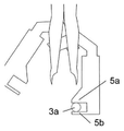
5 is a detailed view of the first clamping jaws when the spacing between the crimped conductors is narrow;
6 is a detailed view of the first clamping jaws when the gap is wide;
Figure 7 is a perspective view of a twisting head joining spaced conductors;
Figure 8 is a perspective view of a twisting head joining spaced conductors;
9 is a perspective view of the feeder in the standby position;
10 is a perspective view of a feeder in which the first linear gripper is in place;
11 is a perspective view of the feeder of Fig. 10 capturing a first conductor; Fig.
Figure 12 is a perspective view of a feeder pivoted by a first linear gripper;
Figure 13 is a perspective view of the feeder with the second linear gripper in place;
14 is a perspective view of the feeder of Fig. 13 covering the second conductor; Fig.
15 is a perspective view of a feeder in which linear grippers are adjusted for selected conductor separations;
16 is a perspective view of a feeder for transferring to a twisting head;
FIG. 17 is a perspective view of the feeder of FIG. 16 in which the second clamping jaw of the twisted head is actuated;
Fig. 18 is a perspective view of the feeder of Fig. 17 with the first clamping jaws released;
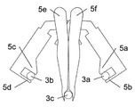
19 is a front view of three grippers in which the first clamping jaw is in the standby position;
Figure 20 is a front view of the gripper of Figure 19 with the first conductor gripped by the first gripper;
Figure 21 is a front view of the gripper of Figure 19 with the second conductor captured by the second gripper and the first gripper pivoted;
Figure 22 is a front view of the gripper of Figure 19, with the first and second grippers pivoted and the third conductor captured with a third gripper;
Figure 23 is a front view of the gripper of Figure 19 with the grippers adjusted for selected conductor separations;
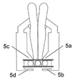
24 is a front view of the gripper of FIG. 23, with the second clamping jaws of the twisted head capturing three conductors;
Figure 25 is a front view of the gripper of Figure 24 with only the first clamping jaws released;
26 is a front view of the gripper of Fig. 25 with the grippers pivoted; Fig.
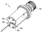
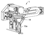
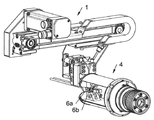
도 1의 트위스팅 장치는 2개이 도체(3a~b)의 도체단부(2a~b)를 공급하는 공급기(1)와, 도체(3a~b)를 꼬기 위해 회전하도록 설치된 트위스팅 헤드(4)를 포함한다. 따라서, 트위스팅 헤드(4)는 후처리 장치를 형성한다. 공급기(1)는 제1 클램핑조(5a~d)를 갖고 트위스팅 헤드(4)는 도체단부(2a~b)를 조이기 위한 제2 클램핑조(6a~b)를 갖는데, 도 1에서는 클램핑조(5b)가 도체(3a)로 가려져 보이지 않는다. 공급기(1)와 트위스팅 헤드(4)는 서로에 대해 움직이면서 운반위치로 이동할 수 있고, 이 위치에서 제1 클램핑조(5a~d)와 제2 클램핑조(6a~b)는 서로 반대로 위치하여, 공급기(1)에서 트위스팅 헤드(4)로 도체단부(2a~b)를 옮길 수 있다. 트위스팅 헤드(4)의 도움으로, 도체(3a~b)를 공지의 방식으로 꼬아 예컨대 쌍꼬임선을 만들 수 있다. The twisting apparatus of Fig. 1 comprises a
조임 위치에 있는 제1 클램핑조(5a~d)는 서로 상대 운동하면서 조임상태의 도체단부들(2a~b)의 간격을 조절할 수 있다. 이를 위해, 제1 클램핑조(5a~d)의 드라이브(8)에 컨트롤러(7)를 연결하여, 트위스팅 헤드(4)로 옮기기 전에 도체단부들(2a~b)의 간격을 적절한 값으로 설정한다. 이런 간격조절 방법에 대해서는 뒤에 자세히 설명한다.The
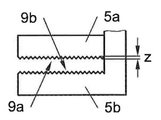
도 2는 조임면(9a~b)이 평면이면서 서로 마주보고 있는 제1 클램핑조(5a~b)의 정면도이다. 여기서는 클램핑조(5a~b)가 완전히 개방된 위치에 있다. 완전개방 상태의 제1 클램핑조(5a~b) 사이의 공간의 폭 b는 간격의 높이 h보다 크고 도체단부(2a)의 위치를 바꾸기 위한 이동방향(A)으로 측정한 길이이며, h는 도체단부(2a)를 조이는 조임방향(B)으로 측정한 길이이다. b는 h의 2배 이상인 것이 좋다. 즉, 완전개방되었을 때의 제1 클램핑조(5a~b) 사이의 공간은 도체단부(2a)를 조이기 위한 조임방향(B)의 길이에 비해 도체단부의 간격을 조절하기 위한 이동방향(A)의 길이가 2배 이상이다. 이런 조치를 통해, 도체(3a)나 도체단부(2a)를 제1 클램핑조(5a~b) 사이의 어느 위치에서도 조일 수 있다.Fig. 2 is a front view of the
한편, b를 도체(3a)나 도체단부(2a)의 직경(d)의 2배 이상으로 할 수도 있다. 요컨대, 완전히 개방된 제1 클램핑조(5a~b) 사이의 공간이 이동방향(A)으로 길이는 도체(3a)나 도체단부(2a)의 직경의 2배 이상이다. On the other hand, b may be made twice or more as large as the diameter d of the
또는, b를 9mm 이상으로 할 수도 있다. 즉, 완전히 개방된 제1 클램핑조(5a~b) 사이의 공간이 이동방향(A)으로 길이가 9mm 이상이다.Alternatively, b may be 9 mm or more. That is, the space between the
도 3은 조임면(9a~b)에 톱니가 달린 형태를 보여준다. 톱니의 높이 z는 직경 d의 10%보다 작거나 높이 h의 3%보다 작게 하여, 조임면(9a~b)이 기본적으로 평탄을 유지하면서 도체(3a)나 도체단부(2a)를 클램핑조(5a~b) 사이의 어떤 위치에서도 조일 수 있도록 하는 것이 좋다. 이런 톱니 때문에 도 2의 실시예의 형태보다 조임 기능이 더 효과적으로 된다.Fig. 3 shows a saw tooth shape on the fastening surfaces 9a to 9b. The height z of the saw tooth is made smaller than 10% of the diameter d or less than 3% of the height h so that the clamping surfaces 9a to 9b are kept flat while the
이런 형태의 트위스팅 장치가 꼬는 도체(3a~b)는 단면적이 0.35~2.5㎟이고 직경은 최대 3mm이다. 폭 b가 9mm인 클램핑조들의 경우, 이런 도체(3a~b)의 중심간 거리는 최대 15mm이다(도 5~6의 거리 참조). 톱니 높이는 0.2mm이다. 이런 값들이 유리하기는 해도 필수적인 것은 아니다. 트위스팅 장치가 대형 도체(3a~b)를 처리할 수만 있으면 그 치수들도 이에 맞춰 늘일 수 있다.The
도 4는 도체(3a)나 도체단부(2a)를 끼우기 위한 반원형 홈을 각각 4개씩 갖춘 조임면(9a~b)을 갖는 변형례를 보여준다. 홈의 깊이 t는 도체나 도체단부의 직경(d)의 절반보다 약간 작다. 따라서, 도체(3a)나 도체단부(2a)를 클램프조(5a~b) 사이의 didWHr 홈으로 조일 수 있다. 조임면의 홈 수도 4개보다 적거나 많을 수 있지만, 1개 이상이 좋고 2개 이상이면 더 좋다.Fig. 4 shows a modification example in which the clamping surfaces 9a to 9b each having four semicircular grooves for clamping the
도 5~6은 도체(3a~b) 사이, 즉 도체단부(2a~b) 사이의 간격이 공급기(1)에서 조여지는 위치에 따라 어떻게 변하는지를 보여준다. 상부 도면에 클램핑조(5a~d)와 2개의 조여진 도체(3a~b)가 같이 도시되었고, 하부 도면은 도체(a~b)가 꼬인 상태를 보여준다.5 to 6 show how the distance between the
도 5의 도체(3a~b)는 작은 간격을 두고 조여진 상태를, 도 6에서는 이 간격이 커진 상태를 보여준다. 꼬는 동안에는 이들 간격이 유지되어야 한다는 예상하여, 단부 구간들 각각의 꼬이지 않은 길이(l)가 생긴다. 도 7은 도 5의 도체(3a~b)가 트위스팅 헤드(4)의 2개의 클램필조(6a~b) 사이에서 조이는 상태를, 도 8은 도 6의 도체(3a~b)가 트위스팅 헤드(4)의 2개의 클램핑조(6a~b) 사이에서 조이는 상태를 각각 보여준다. 트위스팅 헤드(4)를 회전시키기 위해, 구동 피니언(도시 안됨)이나 구동벨트에 맞물리는 기어(10)가 트위스팅 헤드에 배치된다. 도 6에 도시된 꼬이지 않은 단부구간은 도 5의 꼬이지 않은 단부구간보다 길다.The
필요하만큼 작은 접점과 시일들을 갖는 가느다란 도체(3a~b)는 큰 접점과 시일들을 갖는 더 굵은 도체(3a~b)보다 좁은 간격으로 배열된다. 이렇게 하여 기능한 최대 길이로 도체(3a~b)를 꼬을 수 있다.The
앞의 도면들에서는 조임 위치에 있는 제1 클램핑조(5a~d)를 서로에 대해 움직여 조여진 2개의 도체단부(2a~b) 사이의 간격을 조절할 수 있고, 그 결과 도체단부(2a~b)가 다양하게 떨어진 쌍꼬임선을 만들 수 있다.In the preceding figures, the
한편, 이런 형태가 유일한 것은 아니고, 조임위치에 있는 제1 클램핑조(5a~d)가 서로에 대해 움직이면서 3개의 조인 도체단부들의 간격을 조절할 수도 있다(도 19~26 참조). 이렇게 하여 도체단부들이 서로 떨어져 있는 삼꼬임선을 만들 수 있다.On the other hand, this form is not unique, and the spacing of the three joined conductor ends may be adjusted as the
공급기(1)와 트위스팅 헤드(4)를 이용해 2개의 도체(3a~b)를 꼬는 방법에 대해 도 9~18을 참조하여 설명한다. A method of twisting the two
도 9는 제1 도체가 이미 제1 클램핑조(5a~b) 부근에 위치하면서 아직 조여지지 않은 상태의 도 1의 공급기(1)를 보여준다. 시일(12a)이 달린 도체(3a)에 접점(11a)이 배열되어 있다. 시일과 접점 둘다 도체(3a)의 단면적보다 돌출하여, 도체(3a~b) 사이에 생길 수 있는 최소의 간격을 결정한다. Fig. 9 shows the
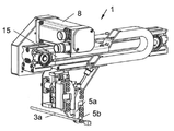
도 9에는 클램핑조(5a~d)가 달린 2개의 선형 그립퍼(13a~b), 공압 램(14), 수평가이드(15), 움직일 수 있도록 수평가이드에 설치된 캐리지(16), 및 피봇베어링(17)이 보이는데, 제1 선형 그립퍼(13a)는 수직가이드(18)와 함께 회전할 수 있도록 피봇베어링(17)에 설치되고, 제2 선형 그립퍼(13b)는 위아래로 움직일 수 있도록 수직가이드에 설치된다. 드라이브(8)의 도움으로, 캐리지(16)와 캐리지에 설치된 선형 그립퍼(13a~b)가 수평가이드(15)를 따라 수평으로 움직일 수 있다. 또, 제1 선형 그립퍼(13a)는 공압 램(14)의 도움으로 피봇베어링(17)에 대해 피봇할 수 있다. 끝으로, 제2 선형 그립퍼는 공압 수단에 의해 수직가이드(18)를 따라 위아래로 움직일 수 있다. 클램핑조(5b,5d)는 클램핑조(5a,5c)에 대해 상대운동할 수 있다. 물론 다른 형태의 드라이브, 예컨대 전기식이나 유압식 드라이브를 공압식 대신에 사용할 수도 있다. 도 9에 도시된 첫번째 상태에서, 제1 선형 그립퍼(13a)는 위로 피봇하고, 제2 선형 그립퍼(13b)는 위로 움직이며, 클램핑조(5a~d)는 개방된다.9 shows two
도 10의 공급기(1)는 두번째 상태에 있는데, 이때 제1 선형 그립퍼(13a)는 아래로 피봇하고 제2 선형 그립퍼(13b)는 전처럼 위로 움직이며, 클램핑조(5a~d)도 아직 개방되어 있다. The
도 11은 다른 상태의 공급기(1)로서, 이때 클램핑조(5a~b)는 닫혀 도체(3a)를 조인다. 조이기 전에 제1 선형 그립퍼(13a)는 컨트롤러(7)와 드라이버(8)의 도움으로 도체(3a)의 원하는 위치에 맞게 수평으로 위치한다. Fig. 11 is a
도 12의 공급기(1)는 또다른 상태에 있는데, 이때 제1 선형 그립퍼(13a)는 도체(3a)를 조은채 윗쪽으로 피봇하고, 제2 선형 그립퍼(13b)는 아래로 이동하며, 클램핑조(5c~d)는 아직 열려있다. 도체(3b)는 이미 클램핑조(5c~d) 근방에 배열되어 있다.The
도 13의 공급기(1) 상태에서는 제2 선형 그립퍼(13b)가 컨트롤러(7)와 드라이브(8)의 도움으로 도체(3b)의 필요 위치에 맞게 수평으로 위치해있다.13, the second
도 14이 공급기 상태에서는, 클램핑조(5c~d)가 닫혀 도체(3b)를 조이고 있다.In the feeder state of Fig. 14, the clamping
도 15의 공급기(1)와 트위스팅 헤드(4) 상태에서는 제1 선형 그립퍼(13a)가 아래로 피봇하고 도체(3a~b)는 필요한 간격으로 서로 벌어져 있다.15, the first
도 16의 공급기(1)와 트위스팅 헤드(4) 상태에서는 공급기(1)가 트위스팅 헤드(4)와 같이 운반위치로 이동해있고, 공급기(1)의 제1 클램핑조(5a~d)와 트위스팅 헤드(4)의 제2 클램핑조(6a~b)는 서로 반대로 위치해있다. In the state of the
도 17의 공급기(1)와 트위스팅 헤드(4) 상태에서는 트위스팅 헤드의 제2 클램핑조(6a~b)가 닫혀 도체(3a~b)를 조이고 있다.17, the
도 18의 공급기(1)와 트위스팅 헤드(4) 상태에서는 공급기(1)의 제1 클램핑조(5a~d)가 열려 도체(3a~b)가 트위스팅 헤드(4)로 이동해있다. 이때 제1 선형 그립퍼(13a)는 이미 윗쪽으로 피봇해있어, 공급기(1)가 트위스팅 헤드(4) 부근에서 벗어날 수 있다. 다른 도체단부들(도시 안됨)을 고정하고 트위스팅 헤드(4)를 회전시키면 도체(3a~b)를 전술한 방식으로 꼬을 수 있다.18, the
제1 클램핑조(5a~d)가 달린 공급기(1)와, 제2 클램핑조(6a~b)가 달린 트위스팅 헤드(4)를 갖춘 트위스팅 장치(1)를 이용해 적어도 2개의 도체(3a~b)를 꼬는 방법은 아래 단계들을 포함한다:A
- 공급기(1)의 제1 클램핑조(5a~d) 사이에 도체(3a~b)의 도체단부(2a~b)를 조이는 단계;- clamping the conductor ends (2a-b) of the conductors (3a-b) between the first clamping jaws (5a-d) of the feeder (1);
- 공급기(1)를 트위스팅 헤드(4)와 같이 운반위치로 이동시켜, 공급기의 제1 클램핑조(5a~d)와 트위스팅 헤드의 제2 클램핑조(6a~b)를 서로 반대로 위치시키는 단계;The
- 트위스팅 헤드(4)의 제2 클램핑조(6a~b) 사이에 도체단부(2a~b)를 조이는 단계;- fastening the conductor ends (2a-b) between the second clamping jaws (6a-b) of the twisting head (4);
- 공급기(1)의 제1 클램핑조(5a~d)를 푸는 단계; 및- unfastening the first clamping jaw (5a-d) of the feeder (1); And
- 트위스팅 헤드(4)를 회전시켜 도체(3a~b)를 꼬는 단계.- twisting the conductors (3a-b) by rotating the twisting head (4).
조여진 도체단부(2a~b)의 간격은 트위스팅 헤드(4)의 제2 클램핑조(6a~b)로 도체단부(2a~b)를 조이기 전의 조임위치로 제1 클램핑조(5a~d)를 움직여 조절값으로 설정할 수 있다. 특히, 이 간격으로 2가지 이상의 값을 선택할 수 있다.The spacing of the twisted conductor ends 2a to b is adjusted by the
도시된 실시예에서, 도체단부(2a~b)를 개별적이고 순서대로 공급기(1)로 조이고, 그와 동시에 트위스팅 헤드(4)로도 조인다. 그러나, 도체단부(2a~b)를 공급기(1)로 동시에 조일 수도 있다. In the embodiment shown, the conductor ends 2a-b are individually and in turn screwed into the
또, 도체단부(2a~b)를 조이기 전에 선택된 간격에 맞게 제1 클램핑조(5a~d)의 위치를 조정하고, 트위스팅 헤드(4)의 제2 클램핑조(6a~b)로 도체단부를 조이기 전에 제1 클램핑조(5a~d)를 고정 위치로 이동시킨다. 이때, 도 2~6에서 보듯이, 수평가이드(15)와 함께 선형 그립퍼(13a~b)가 수평으로 움직일 수 있다. 엄밀히 말해, 트위스팅 헤드(4)에서 원하는 간격은 공급기(1)에 의핸 조임과정 동안 이마 정해지고, 도체단부(2a~b)를 캡처할 때 선형 그립퍼(13a~b)는 적당한 위치로 이동한다(도 10, 13 참조). 반면에, 트위스팅 헤드(4) 위치로 이동하는 동안 선형 그립퍼(13a~b)의 위치가 고정된다. 즉, 도체단부(2a~b)를 트위스팅 헤드로 옮기기 위해 선형 그립퍼(13a~b)는 항상 같은 위치로 이동된다.Before the conductor ends 2a to b are tightened, the positions of the
도체단부(2a~b)를 조이기 위해 제1 클램핑조(5a~d)는 서로에 대해 움직일 수 있도록 설치되고, 조여진 도체단부(2a~b)의 간격을 조절하기 위해서는 클램핑 위치에 영향을 주지 않고 제1 클램핑조를 서로에 대해 회전할 수 있도록 설치하는 것이 일반적이다(도 1~18 참조). 그러나, 도체단부(2a~b)를 조이고 조여진 도체단부들의 간격을 조절하는 두가지 목적으로 제1 클램핑조(5a~b)를 서로에 대해 움직일 수 있도록 설치하는 것도 고려할 수 있다. 마찬가지로, 도체단부들을 조이면서 그 간격을 조절할 목적으로 제1 클램핑조를 서로에 대해 회전하도록 설치할 수도 있다. 끝으로, 도체단부들을 조이기 위해 제1 클램핑조들을 서로에 대해 회전하도록 설치하고, 도체단부의 간격을 조절하기 위해 제1 클램핑조들을 조임위치에 영향을 주지 않고 서로에 대해 움직일 수 있도록 설치할 수도 있다.The
또, 제2 클램핑조(6a~b)도 도 1~18에서 처럼 도체단부(2a~b)를 조이기 위해 서로에 대해 움직일 수 있도록 설치하되, 회전도 할 수 있도록 설치할 수도 있다. 또, 도 2~4에서처럼 제2 클램핑조(6a~b)를 설계하는 것도 고려할 수 있다. 즉, 조임면이 서로를 향하도록 제2 클램핑조를 설계할 수 있고, 이때 조임면들을Also, the
c) 평탄하게 하거나c) flattening
d) 도체단부(2a~b) 각각을 수용하기 위한 반원형 홈들을 2 또는 3개 이상으로 할 수 있다. d) Two or three or more semicircular grooves may be provided for receiving each of the conductor ends 2a-b.
도 19~26은 3개의 도체(3a~c)를 조이고 꼬는 일례를 보여준다.Figs. 19-26 show an example of twisting and twisting three
도 19의 제1 클램핑조(5a~f)는 초기 위치에 있고 제1 도체(3a)가 공급기(1) 부근에 위치한다.The
도 20의 상태에서는 클램핑조(5a~b)가 제1 도체(3a)에 직교하면서 제1 도체를 캡처하고 조인다.In the state of Fig. 20, the clamping
도 21의 상태에서는 클램핑조(5c~d)가 제2 도체(3b)에 직교하면서 공급기(1) 근처에 있고 제2 도체를 캡처해 조인다. 그동안 제1 도체(3a)를 조인 클램핑조(5a~b)는 도체(3b) 부근에서 벗어난다. In the state of Fig. 21, the clamping
도 22의 상태에서는 클램핑조(5e~f)가 제3 도체(3c)에 직교한채 공급기 부근에 와서 제3 도체를 캡처하고 조인다. 그동안, 제2 도체(3b)를 조이고 있는 클램핑조(5c~d)는 도체(3c) 부근에서 벗어난다.In the state of Fig. 22, the clamping
이어서 클램핑조(5a~f)가 서로를 향해 움직이면서 3개의 도체(3a~c)를 트위스팅 헤드(4) 위치로 이동한다(도 23 참조). Then, the three
도 24에서, 도체(3a~c)가 트위스팅 헤드(4)의 제2 클램핑조(6a~b)에 의해 캡처되어 조여진다. 그러나, 전과 마찬가지로 이들 도체(3a~c)는 여전히 공급기(1)의 클램핑조(5a~f)에 의해 계속 조여져 있다. 반면에, 도 25에서는 클램핑조(5a~d)가 이미 풀려있다. In Fig. 24, the
도 26의 마지막 상태에서 클램핑조(5a~f)가 모두 도체(3a~c) 부근을 벗어나고, 이들 도체는 트위스팅 헤드(4)에 조여져 있다. 이들 도체는 이어서 전술한 방식으로 꼬여진다. 26, all of the clamping
도 1~18에서 설명한 실시예들도 도 19~26에서 설명한 실시예들과 마찬가지로 적용할 수 있다. 특히, 제1 클램핑조(5a~f)와 제2 클램핑조(6a~b)의 형태와 설치에 관해 그렇다.The embodiments described in FIGS. 1 to 18 can be applied similarly to the embodiments described in FIGS. 19 to 26. Particularly, it relates to the form and installation of the
이상 설명한 공급기(1)가 도체(3a~c)를 꼬는데 유리하고 도 1~18의 실시예들을 이에 대해 설명했지만, 공급기(1)는 이상의 설명에 한정되지 않는다. 다른 방식의 후처리 장치(4)도 고려할 수 있다. 예컨대, 후처리 장치(4)가 시일(12a)을 도체단부(2a~b)에 밀어박는 자동기기나, 접점(11a)을 도체단부(2a~b)에 압입하는 자동 기기의 형태일 수도 있다. 일반적으로 접점(11a)의 시일(12a)의 크기에 맞춰 도체(3a~c) 사이의 간격을 적절히 조절해야 하는 것이 문제인데, 특히 시일(12a)이나 접점(11a)이 다수의 도체(3a~c)를 수용하고 이런 시일이나 접점을 압입하는 동안 도체들 사이의 간격을 제대로 맞추어야 할 경우 더 그렇다. 다수의 시일(12a) 및/또는 접점(11a)을 동시에 다수의 도체(3a~c)에 압입해야할 경우 더 문제이다. 물론, 이런 일을 할 수 있는 자동 기기도 고려할 수 있다.Although the
Claims (17)
상기 공급기(1)가 도체단부(2a~c)를 조이기 위한 제1 클램핑조(5a~f)를 갖추고, 후처리 장치(4)는 도체단부(2a~c)를 조이기 위한 제2 클램핑조(6a~b)를 갖추며, 공급기(1)와 후처리 장치(4)가 서로에 대해 움직이면서 운반위치로 이동할 수 있고, 운반위치에서 제1 클램핑조(5a~f)와 제2 클램핑조(6a~b)가 서로 반대로 위치하며, 조임위치에 있는 제1 클램핑조(5a~f)는 서로에 대해 움직이면서 도체단부(2a~b) 사이의 간격을 조절할 수 있고;
완전히 열린 제1 클램핑조(5a~f) 사이에 있는 공간의 크기가 조여진 도체단부(2a~c) 사이의 간격을 조절하기 위한 이동방향(A)으로의 길이가 도체단부를 조이는 제1 클램핑조(5a~f)의 조임방향(B)으로의 길이보다 2배 이상인 것을 특징으로 하는 공급기.A feeder (1) for feeding conductor ends (2a to c) of at least two conductors (3a to c) to a post-treatment apparatus (4) of conductors (3a to c)
The feeder 1 is equipped with a first clamping jaw 5a-f for clamping the conductor ends 2a-c and the post-treatment device 4 is provided with a second clamping jaw 5a-f for clamping the conductor ends 2a-c, 6a to 6b and the feeder 1 and the post-processing apparatus 4 can move to the conveying position while moving relative to each other and the first clamping jaws 5a to 5f and the second clamping jaws 6a- b are opposite to each other and the first clamping jaws 5a-f in the tightening position are able to adjust the distance between the conductor ends 2a-b while moving relative to each other;
The length in the moving direction A for adjusting the distance between the conductor ends 2a-c, which are tightened in the space between the fully opened first clamping tanks 5a-f, Is twice or more the length in the tightening direction (B) of the feed screw (5a-f).
a) 평탄하거나,
b) 도체단부(2a~c) 각각을 수용하는 반원형 홈을 하나 이상 갖는 것을 특징으로 하는 공급기.The clamping device according to any one of claims 1 to 4, wherein the first clamping jaws (5a-f) have clamping surfaces (9a-b) facing each other,
a) flat,
b) one or more semicircular grooves for receiving each of the conductor ends (2a-c).
회전하도록 설치된 트위스팅 헤드를 포함하고, 이런 트위스팅 헤드는 제1항 내지 제9항 중의 어느 하나에 따른 공급기(1)와 함께 후처리 장치(4)를 형성하는 것을 특징으로 하는 트위스팅 장치.A twisting device (1) for twisting at least two conductors (3a-c), comprising:
Characterized in that the twistening head is provided with a twistening head which is mounted for rotation and which, together with the feeder (1) according to any one of the claims 1 to 9, forms a post-treatment device (4).
c) 평탄하거나,
d) 도체단부(2a~c) 각각을 수용하는 반원형 홈을 2개 이상 갖는 것을 특징으로 하는 트위스팅 장치. 11. The clamping device according to claim 10, wherein the second clamping jaws (6a-b) have clamping surfaces facing each other,
c) flat,
and d) two or more semicircular grooves for receiving each of the conductor ends (2a-c).
- 공급기(1)의 제1 클램핑조(5a~f) 사이에 도체(3a~c)의 도체단부(2a~c)를 조이는 단계;
- 공급기(1)를 후처리 장치(4)와 같이 운반위치로 이동시켜, 공급기의 제1 클램핑조(5a~f)와 후처리 장치의 제2 클램핑조(6a~f)를 서로 반대로 위치시키는 단계;
- 후처리 장치(4)의 제2 클램핑조(6a~b) 사이에 도체단부(2a~c)를 조이는 단계;
- 공급기(1)의 제1 클램핑조(5a~f)를 푸는 단계; 및
- 후처리 장치(4)에서 상기 도체(3a~c)를 더 처리하는 단계;를 포함하고,
도체단부(2a~c)를 조이기 전에 도체단부 사이의 선택된 간격(a)에 맞게 제1 클램핑조(5a~f)의 위치를 조절하고, 후처리 장치(4)의 제2 클램핑조(6a~b)로 도체단부(2a~c)를 조이기 전에 제1 클램핑조(5a~f)를 소정의 고정 위치로 이동시키는 것을 특징으로 하는 방법.The first clamping jaws 5a-f are used to clamp at least two conductors 3a-c with the aid of the feeder 1 while the second clamping jaws 6a- (3a-c), comprising:
- clamping the conductor ends (2a-c) of the conductors (3a-c) between the first clamping jaws (5a-f) of the feeder (1);
The feeder 1 is moved to a transport position such as aftertreatment device 4 so that the first clamping jaws 5a-f of the feeder and the second clamping jaws 6a-f of the post- step;
- fastening the conductor ends (2a-c) between the second clamping jaws (6a-b) of the after-treatment device (4);
- releasing the first clamping jaw (5a-f) of the feeder (1); And
- further processing said conductors (3a-c) in post-treatment apparatus (4)
The positions of the first clamping jaws 5a-f are adjusted to fit the selected gap a between the conductor ends before tightening the conductor ends 2a-c, and the second clamping jaws 6a- b) to move the first clamping jaw (5a-f) to a predetermined fixed position before tightening the conductor ends (2a-c).
Process according to any one of claims 13 to 16, characterized in that the aftertreatment device comprises at least one seal (12a) for the purpose of twisting at least two conductors (3a-c) and / And / or for twisting the head (4) for the purpose of inserting at least one contact (11a) into the conductors (3a-c).
Applications Claiming Priority (2)
| Application Number | Priority Date | Filing Date | Title |
|---|---|---|---|
| EP14190323.7A EP3012841A1 (en) | 2014-10-24 | 2014-10-24 | Device for feeding pipe ends to a processing device |
| EPEP14190323.7 | 2014-10-24 |
Publications (1)
| Publication Number | Publication Date |
|---|---|
| KR20160048663A true KR20160048663A (en) | 2016-05-04 |
Family
ID=51865987
Family Applications (1)
| Application Number | Title | Priority Date | Filing Date |
|---|---|---|---|
| KR1020150145897A KR20160048663A (en) | 2014-10-24 | 2015-10-20 | A device for purposes of feeding conductor ends to a further-processing device |
Country Status (5)
| Country | Link |
|---|---|
| EP (1) | EP3012841A1 (en) |
| JP (1) | JP2016085973A (en) |
| KR (1) | KR20160048663A (en) |
| CN (1) | CN105551689B (en) |
| SG (1) | SG10201508422RA (en) |
Families Citing this family (7)
| Publication number | Priority date | Publication date | Assignee | Title |
|---|---|---|---|---|
| DE102016109155B3 (en) | 2016-05-18 | 2017-08-03 | Lisa Dräxlmaier GmbH | Twisting machine, tandem twisting machine and method for loading a twisting head |
| EP3301768B1 (en) | 2016-10-03 | 2021-06-16 | Komax Holding AG | Method and device for rotational alignment of preconfigured cable ends of a wire harness |
| RS59998B1 (en) | 2016-10-03 | 2020-04-30 | Komax Holding Ag | Vorrichtung und verfahren zum bestücken eines steckergehäuses mit konfektionierten kabelenden eines kabelstrangs |
| CN108394749B (en) * | 2018-04-02 | 2023-05-30 | 浙江一丁点工艺品有限公司 | Fluff strip feeding device |
| EP3557592B1 (en) | 2018-04-17 | 2021-01-20 | Komax Holding Ag | Device and method for twisting a first and second electrical single wire line to form a cable pair |
| CN110509201B (en) * | 2019-09-25 | 2024-02-20 | 台州市圣西亚金刚石设备有限公司 | Method for conveying and positioning tool bit by tool bit conveying device |
| US20240120696A1 (en) * | 2022-10-07 | 2024-04-11 | Te Connectivity Solutions Gmbh | Wire Processing Device |
Family Cites Families (10)
| Publication number | Priority date | Publication date | Assignee | Title |
|---|---|---|---|---|
| US4194281A (en) * | 1978-09-25 | 1980-03-25 | Artos Engineering Company | Apparatus and method for stripping wire leads |
| CH673858A5 (en) * | 1986-12-03 | 1990-04-12 | Megomat Ag | Cable sections make-up set - consisting of two grippers, two auxiliary grippers, and cutting stripping unit for cable press |
| DE59914354D1 (en) * | 1998-08-31 | 2007-07-12 | Komax Holding Ag | Device for merging ladders |
| EP0984530B1 (en) * | 1998-08-31 | 2007-05-30 | komax Holding AG | Device for bringing conductors together |
| US6243947B1 (en) * | 1998-09-22 | 2001-06-12 | Sumitomo Wiring Systems, Ltd. | Method for processing an end of a shielded cable |
| EP1032095B1 (en) | 1999-02-23 | 2013-05-22 | Komax Holding AG | Method and device for processing and twisting a conductor pair |
| US6289944B1 (en) * | 1999-02-23 | 2001-09-18 | Komax Holding Ag | Method and equipment for the treatment and twisting together of a conductor pair |
| JP2003217371A (en) * | 2002-01-23 | 2003-07-31 | Auto Network Gijutsu Kenkyusho:Kk | Method and device for manufacturing twisted pair wire |
| CH700897B1 (en) * | 2009-04-24 | 2014-02-14 | Schleuniger Holding Ag | Apparatus and method for merging conductors for producing a double crimp. |
| JP6282929B2 (en) * | 2014-05-16 | 2018-02-21 | 日本オートマチックマシン株式会社 | Electric wire twisting device, twisted cable manufacturing device, electric wire twisting method, and twisted cable manufacturing method |
-
2014
- 2014-10-24 EP EP14190323.7A patent/EP3012841A1/en not_active Withdrawn
-
2015
- 2015-10-10 SG SG10201508422RA patent/SG10201508422RA/en unknown
- 2015-10-20 KR KR1020150145897A patent/KR20160048663A/en unknown
- 2015-10-23 CN CN201510698233.8A patent/CN105551689B/en not_active Expired - Fee Related
- 2015-10-23 JP JP2015208826A patent/JP2016085973A/en not_active Ceased
Also Published As
| Publication number | Publication date |
|---|---|
| CN105551689A (en) | 2016-05-04 |
| SG10201508422RA (en) | 2016-05-30 |
| JP2016085973A (en) | 2016-05-19 |
| CN105551689B (en) | 2020-02-18 |
| EP3012841A1 (en) | 2016-04-27 |
Similar Documents
| Publication | Publication Date | Title |
|---|---|---|
| KR20160048663A (en) | A device for purposes of feeding conductor ends to a further-processing device | |
| KR20160048662A (en) | A twist application device with an adjustable distance between the conductor ends | |
| JP5400981B1 (en) | Wire twisting device, twisted wire manufacturing device, twisted wire manufacturing method | |
| CN104507813B (en) | For tying up the modularity baling press of steel band | |
| KR101647573B1 (en) | Power line shifting device | |
| WO2007044579A3 (en) | Terminal applicator apparatus, system, and method | |
| KR20180098295A (en) | Pincers | |
| US9124058B2 (en) | Feeding wire-ends to processing units | |
| US9290356B2 (en) | Wire transporting system | |
| US20150372437A1 (en) | Terminal crimping machine having a wire clamp | |
| UA108153C2 (en) | METHOD OF AUTOMATIC SEQUENTIAL INTRODUCTION OF INDIVIDUAL CONNECTORS TO THE CLEANS OF PLATE BUILDING PANELS AND DEVICES FOR DOING THIS | |
| CN114566848B (en) | Wire coating layer stripping device, terminal crimping wire manufacturing device and manufacturing method | |
| JP6282929B2 (en) | Electric wire twisting device, twisted cable manufacturing device, electric wire twisting method, and twisted cable manufacturing method | |
| US6279215B1 (en) | Automatic wire cutting and terminating apparatus | |
| US10840663B2 (en) | Cable processing device | |
| CN106257600B (en) | Electric wire stranding device | |
| KR20170088990A (en) | Centering unit, crimping apparatus and cable processing installation | |
| CN100511878C (en) | Transporter, built-in method of water-proof sealing element for wire and wire processing equipment | |
| US20200076146A1 (en) | Device and method for connecting a cable to an electrical connector | |
| CN110854423A (en) | Winding equipment and pole piece feeding device thereof | |
| CN104379227A (en) | Zipper assembly device | |
| JP5143406B2 (en) | Electric wire manufacturing equipment | |
| US20220166197A1 (en) | Gripper for automated wiring of electrical components of an electrical switchgear, a corresponding robot and a corresponding method | |
| JP6282956B2 (en) | Twist cable manufacturing apparatus and twist cable manufacturing method | |
| JP2016038938A5 (en) |