KR20140133571A - Carbon dopant gas and co-flow for implant beam and source life performance improvement - Google Patents
Carbon dopant gas and co-flow for implant beam and source life performance improvement Download PDFInfo
- Publication number
- KR20140133571A KR20140133571A KR1020147025467A KR20147025467A KR20140133571A KR 20140133571 A KR20140133571 A KR 20140133571A KR 1020147025467 A KR1020147025467 A KR 1020147025467A KR 20147025467 A KR20147025467 A KR 20147025467A KR 20140133571 A KR20140133571 A KR 20140133571A
- Authority
- KR
- South Korea
- Prior art keywords
- gas
- group
- carbon
- compound
- formula
- Prior art date
Links
- 229910052799 carbon Inorganic materials 0.000 title claims abstract description 200
- OKTJSMMVPCPJKN-UHFFFAOYSA-N Carbon Chemical compound [C] OKTJSMMVPCPJKN-UHFFFAOYSA-N 0.000 title claims abstract description 173
- 239000002019 doping agent Substances 0.000 title claims abstract description 151
- 239000007943 implant Substances 0.000 title description 4
- 230000006872 improvement Effects 0.000 title description 2
- 239000007789 gas Substances 0.000 claims abstract description 299
- 239000000463 material Substances 0.000 claims abstract description 95
- 239000000203 mixture Substances 0.000 claims abstract description 64
- 238000000034 method Methods 0.000 claims abstract description 62
- 238000005468 ion implantation Methods 0.000 claims abstract description 30
- 150000004678 hydrides Chemical class 0.000 claims abstract description 16
- 230000008569 process Effects 0.000 claims abstract description 14
- 239000011261 inert gas Substances 0.000 claims abstract description 12
- KRHYYFGTRYWZRS-UHFFFAOYSA-M Fluoride anion Chemical compound [F-] KRHYYFGTRYWZRS-UHFFFAOYSA-M 0.000 claims abstract description 8
- 150000001721 carbon Chemical class 0.000 claims abstract description 8
- -1 Cyclic alkene Chemical class 0.000 claims description 85
- 150000001875 compounds Chemical class 0.000 claims description 75
- 150000002500 ions Chemical class 0.000 claims description 71
- 239000000758 substrate Substances 0.000 claims description 52
- 229910052731 fluorine Inorganic materials 0.000 claims description 43
- 229910002091 carbon monoxide Inorganic materials 0.000 claims description 38
- 229910052760 oxygen Inorganic materials 0.000 claims description 28
- 229910052739 hydrogen Inorganic materials 0.000 claims description 26
- 229910015275 MoF 6 Inorganic materials 0.000 claims description 21
- 125000004432 carbon atom Chemical group C* 0.000 claims description 21
- 150000004820 halides Chemical class 0.000 claims description 21
- RTZKZFJDLAIYFH-UHFFFAOYSA-N Diethyl ether Chemical class CCOCC RTZKZFJDLAIYFH-UHFFFAOYSA-N 0.000 claims description 16
- 125000000217 alkyl group Chemical group 0.000 claims description 16
- 150000001412 amines Chemical class 0.000 claims description 16
- 150000002148 esters Chemical class 0.000 claims description 16
- YCKRFDGAMUMZLT-UHFFFAOYSA-N Fluorine atom Chemical compound [F] YCKRFDGAMUMZLT-UHFFFAOYSA-N 0.000 claims description 15
- 238000004140 cleaning Methods 0.000 claims description 15
- 239000011737 fluorine Substances 0.000 claims description 15
- 229910052734 helium Inorganic materials 0.000 claims description 14
- 229910052743 krypton Inorganic materials 0.000 claims description 14
- 229910052724 xenon Inorganic materials 0.000 claims description 13
- 229910052786 argon Inorganic materials 0.000 claims description 12
- 239000004065 semiconductor Substances 0.000 claims description 12
- 229910052757 nitrogen Inorganic materials 0.000 claims description 11
- 108010000020 Platelet Factor 3 Proteins 0.000 claims description 10
- 229910052754 neon Inorganic materials 0.000 claims description 10
- 125000001153 fluoro group Chemical group F* 0.000 claims description 9
- 239000004215 Carbon black (E152) Substances 0.000 claims description 8
- LFQSCWFLJHTTHZ-UHFFFAOYSA-N Ethanol Chemical compound CCO LFQSCWFLJHTTHZ-UHFFFAOYSA-N 0.000 claims description 8
- 150000001298 alcohols Chemical class 0.000 claims description 8
- 150000001335 aliphatic alkanes Chemical class 0.000 claims description 8
- 150000001336 alkenes Chemical class 0.000 claims description 8
- 150000001345 alkine derivatives Chemical class 0.000 claims description 8
- 150000004945 aromatic hydrocarbons Chemical class 0.000 claims description 8
- 150000001924 cycloalkanes Chemical class 0.000 claims description 8
- 150000002170 ethers Chemical class 0.000 claims description 8
- 125000002485 formyl group Chemical class [H]C(*)=O 0.000 claims description 8
- 150000008282 halocarbons Chemical class 0.000 claims description 8
- 229930195733 hydrocarbon Natural products 0.000 claims description 8
- 150000002430 hydrocarbons Chemical class 0.000 claims description 8
- 150000004291 polyenes Chemical class 0.000 claims description 8
- 150000003141 primary amines Chemical class 0.000 claims description 8
- 150000003335 secondary amines Chemical class 0.000 claims description 8
- 150000003512 tertiary amines Chemical class 0.000 claims description 8
- 238000004519 manufacturing process Methods 0.000 claims description 7
- QVGXLLKOCUKJST-UHFFFAOYSA-N atomic oxygen Chemical compound [O] QVGXLLKOCUKJST-UHFFFAOYSA-N 0.000 claims description 2
- 150000002222 fluorine compounds Chemical class 0.000 claims description 2
- 239000001301 oxygen Substances 0.000 claims description 2
- JCXJVPUVTGWSNB-UHFFFAOYSA-N Nitrogen dioxide Chemical class O=[N]=O JCXJVPUVTGWSNB-UHFFFAOYSA-N 0.000 claims 4
- 230000002708 enhancing effect Effects 0.000 claims 1
- 229910052756 noble gas Inorganic materials 0.000 claims 1
- 238000011065 in-situ storage Methods 0.000 abstract description 3
- 239000012459 cleaning agent Substances 0.000 abstract 1
- UGFAIRIUMAVXCW-UHFFFAOYSA-N Carbon monoxide Chemical compound [O+]#[C-] UGFAIRIUMAVXCW-UHFFFAOYSA-N 0.000 description 29
- 239000000047 product Substances 0.000 description 10
- 238000012360 testing method Methods 0.000 description 8
- 230000000875 corresponding effect Effects 0.000 description 7
- CURLTUGMZLYLDI-UHFFFAOYSA-N Carbon dioxide Chemical compound O=C=O CURLTUGMZLYLDI-UHFFFAOYSA-N 0.000 description 6
- 238000000605 extraction Methods 0.000 description 6
- 238000002347 injection Methods 0.000 description 5
- 239000007924 injection Substances 0.000 description 5
- 230000008054 signal transmission Effects 0.000 description 5
- GVNVAWHJIKLAGL-UHFFFAOYSA-N 2-(cyclohexen-1-yl)cyclohexan-1-one Chemical compound O=C1CCCCC1C1=CCCCC1 GVNVAWHJIKLAGL-UHFFFAOYSA-N 0.000 description 4
- 241001120493 Arene Species 0.000 description 4
- 229910014033 C-OH Inorganic materials 0.000 description 4
- 101150065749 Churc1 gene Proteins 0.000 description 4
- 229910014570 C—OH Inorganic materials 0.000 description 4
- 102100038239 Protein Churchill Human genes 0.000 description 4
- 125000002619 bicyclic group Chemical group 0.000 description 4
- 238000010884 ion-beam technique Methods 0.000 description 4
- 238000012423 maintenance Methods 0.000 description 4
- 238000002156 mixing Methods 0.000 description 4
- 125000000018 nitroso group Chemical group N(=O)* 0.000 description 4
- 238000002360 preparation method Methods 0.000 description 4
- 229910002092 carbon dioxide Inorganic materials 0.000 description 3
- 239000001569 carbon dioxide Substances 0.000 description 3
- 230000000694 effects Effects 0.000 description 3
- 238000012544 monitoring process Methods 0.000 description 3
- 125000001424 substituent group Chemical group 0.000 description 3
- WFKWXMTUELFFGS-UHFFFAOYSA-N tungsten Chemical compound [W] WFKWXMTUELFFGS-UHFFFAOYSA-N 0.000 description 3
- 229910052721 tungsten Inorganic materials 0.000 description 3
- 239000010937 tungsten Substances 0.000 description 3
- 239000002041 carbon nanotube Substances 0.000 description 2
- 229910021393 carbon nanotube Inorganic materials 0.000 description 2
- 238000000151 deposition Methods 0.000 description 2
- 230000008021 deposition Effects 0.000 description 2
- 238000002513 implantation Methods 0.000 description 2
- 239000012212 insulator Substances 0.000 description 2
- 238000004377 microelectronic Methods 0.000 description 2
- 150000002894 organic compounds Chemical class 0.000 description 2
- 239000000126 substance Substances 0.000 description 2
- 239000013077 target material Substances 0.000 description 2
- 235000012431 wafers Nutrition 0.000 description 2
- SNRUBQQJIBEYMU-UHFFFAOYSA-N Dodecane Natural products CCCCCCCCCCCC SNRUBQQJIBEYMU-UHFFFAOYSA-N 0.000 description 1
- UFHFLCQGNIYNRP-UHFFFAOYSA-N Hydrogen Chemical compound [H][H] UFHFLCQGNIYNRP-UHFFFAOYSA-N 0.000 description 1
- 239000003463 adsorbent Substances 0.000 description 1
- 150000001450 anions Chemical class 0.000 description 1
- 238000000429 assembly Methods 0.000 description 1
- 125000004429 atom Chemical group 0.000 description 1
- 125000000484 butyl group Chemical group [H]C([*])([H])C([H])([H])C([H])([H])C([H])([H])[H] 0.000 description 1
- 150000001768 cations Chemical class 0.000 description 1
- 239000007795 chemical reaction product Substances 0.000 description 1
- 239000003153 chemical reaction reagent Substances 0.000 description 1
- 238000004891 communication Methods 0.000 description 1
- 239000000470 constituent Substances 0.000 description 1
- 230000002596 correlated effect Effects 0.000 description 1
- 125000002704 decyl group Chemical group [H]C([H])([H])C([H])([H])C([H])([H])C([H])([H])C([H])([H])C([H])([H])C([H])([H])C([H])([H])C([H])([H])C([H])([H])* 0.000 description 1
- 239000003599 detergent Substances 0.000 description 1
- 238000010586 diagram Methods 0.000 description 1
- 238000009792 diffusion process Methods 0.000 description 1
- 125000003438 dodecyl group Chemical group [H]C([H])([H])C([H])([H])C([H])([H])C([H])([H])C([H])([H])C([H])([H])C([H])([H])C([H])([H])C([H])([H])C([H])([H])C([H])([H])C([H])([H])* 0.000 description 1
- 238000010891 electric arc Methods 0.000 description 1
- 238000005530 etching Methods 0.000 description 1
- 125000001495 ethyl group Chemical group [H]C([H])([H])C([H])([H])* 0.000 description 1
- 238000013467 fragmentation Methods 0.000 description 1
- 238000006062 fragmentation reaction Methods 0.000 description 1
- 239000008246 gaseous mixture Substances 0.000 description 1
- 125000003187 heptyl group Chemical group [H]C([*])([H])C([H])([H])C([H])([H])C([H])([H])C([H])([H])C([H])([H])C([H])([H])[H] 0.000 description 1
- 125000005842 heteroatom Chemical group 0.000 description 1
- 125000004051 hexyl group Chemical group [H]C([H])([H])C([H])([H])C([H])([H])C([H])([H])C([H])([H])C([H])([H])* 0.000 description 1
- 239000001257 hydrogen Substances 0.000 description 1
- 239000012535 impurity Substances 0.000 description 1
- 230000003993 interaction Effects 0.000 description 1
- DNNSSWSSYDEUBZ-UHFFFAOYSA-N krypton atom Chemical compound [Kr] DNNSSWSSYDEUBZ-UHFFFAOYSA-N 0.000 description 1
- 229910052751 metal Inorganic materials 0.000 description 1
- 239000002184 metal Substances 0.000 description 1
- 125000002496 methyl group Chemical group [H]C([H])([H])* 0.000 description 1
- 238000012986 modification Methods 0.000 description 1
- 230000004048 modification Effects 0.000 description 1
- QKCGXXHCELUCKW-UHFFFAOYSA-N n-[4-[4-(dinaphthalen-2-ylamino)phenyl]phenyl]-n-naphthalen-2-ylnaphthalen-2-amine Chemical compound C1=CC=CC2=CC(N(C=3C=CC(=CC=3)C=3C=CC(=CC=3)N(C=3C=C4C=CC=CC4=CC=3)C=3C=C4C=CC=CC4=CC=3)C3=CC4=CC=CC=C4C=C3)=CC=C21 QKCGXXHCELUCKW-UHFFFAOYSA-N 0.000 description 1
- 125000000449 nitro group Chemical class [O-][N+](*)=O 0.000 description 1
- 239000000615 nonconductor Substances 0.000 description 1
- 125000001400 nonyl group Chemical group [H]C([*])([H])C([H])([H])C([H])([H])C([H])([H])C([H])([H])C([H])([H])C([H])([H])C([H])([H])C([H])([H])[H] 0.000 description 1
- 125000002347 octyl group Chemical group [H]C([*])([H])C([H])([H])C([H])([H])C([H])([H])C([H])([H])C([H])([H])C([H])([H])C([H])([H])[H] 0.000 description 1
- 230000003287 optical effect Effects 0.000 description 1
- 230000005693 optoelectronics Effects 0.000 description 1
- 125000001181 organosilyl group Chemical group [SiH3]* 0.000 description 1
- 230000003647 oxidation Effects 0.000 description 1
- 238000007254 oxidation reaction Methods 0.000 description 1
- 125000001147 pentyl group Chemical group C(CCCC)* 0.000 description 1
- 230000002028 premature Effects 0.000 description 1
- 230000003449 preventive effect Effects 0.000 description 1
- 238000012545 processing Methods 0.000 description 1
- 125000001436 propyl group Chemical group [H]C([*])([H])C([H])([H])C([H])([H])[H] 0.000 description 1
- 230000002441 reversible effect Effects 0.000 description 1
- 235000002020 sage Nutrition 0.000 description 1
- 229910052710 silicon Inorganic materials 0.000 description 1
- 239000007787 solid Substances 0.000 description 1
- 238000004544 sputter deposition Methods 0.000 description 1
- 125000002948 undecyl group Chemical group [H]C([*])([H])C([H])([H])C([H])([H])C([H])([H])C([H])([H])C([H])([H])C([H])([H])C([H])([H])C([H])([H])C([H])([H])C([H])([H])[H] 0.000 description 1
Images


Classifications
-
- H—ELECTRICITY
- H01—ELECTRIC ELEMENTS
- H01J—ELECTRIC DISCHARGE TUBES OR DISCHARGE LAMPS
- H01J37/00—Discharge tubes with provision for introducing objects or material to be exposed to the discharge, e.g. for the purpose of examination or processing thereof
- H01J37/30—Electron-beam or ion-beam tubes for localised treatment of objects
- H01J37/317—Electron-beam or ion-beam tubes for localised treatment of objects for changing properties of the objects or for applying thin layers thereon, e.g. for ion implantation
-
- H—ELECTRICITY
- H01—ELECTRIC ELEMENTS
- H01L—SEMICONDUCTOR DEVICES NOT COVERED BY CLASS H10
- H01L21/00—Processes or apparatus adapted for the manufacture or treatment of semiconductor or solid state devices or of parts thereof
- H01L21/02—Manufacture or treatment of semiconductor devices or of parts thereof
- H01L21/04—Manufacture or treatment of semiconductor devices or of parts thereof the devices having at least one potential-jump barrier or surface barrier, e.g. PN junction, depletion layer or carrier concentration layer
- H01L21/18—Manufacture or treatment of semiconductor devices or of parts thereof the devices having at least one potential-jump barrier or surface barrier, e.g. PN junction, depletion layer or carrier concentration layer the devices having semiconductor bodies comprising elements of Group IV of the Periodic System or AIIIBV compounds with or without impurities, e.g. doping materials
- H01L21/26—Bombardment with radiation
- H01L21/263—Bombardment with radiation with high-energy radiation
- H01L21/265—Bombardment with radiation with high-energy radiation producing ion implantation
-
- H—ELECTRICITY
- H01—ELECTRIC ELEMENTS
- H01J—ELECTRIC DISCHARGE TUBES OR DISCHARGE LAMPS
- H01J37/00—Discharge tubes with provision for introducing objects or material to be exposed to the discharge, e.g. for the purpose of examination or processing thereof
- H01J37/02—Details
- H01J37/04—Arrangements of electrodes and associated parts for generating or controlling the discharge, e.g. electron-optical arrangement, ion-optical arrangement
- H01J37/08—Ion sources; Ion guns
-
- H—ELECTRICITY
- H01—ELECTRIC ELEMENTS
- H01J—ELECTRIC DISCHARGE TUBES OR DISCHARGE LAMPS
- H01J37/00—Discharge tubes with provision for introducing objects or material to be exposed to the discharge, e.g. for the purpose of examination or processing thereof
- H01J37/30—Electron-beam or ion-beam tubes for localised treatment of objects
- H01J37/317—Electron-beam or ion-beam tubes for localised treatment of objects for changing properties of the objects or for applying thin layers thereon, e.g. for ion implantation
- H01J37/3171—Electron-beam or ion-beam tubes for localised treatment of objects for changing properties of the objects or for applying thin layers thereon, e.g. for ion implantation for ion implantation
-
- H—ELECTRICITY
- H01—ELECTRIC ELEMENTS
- H01L—SEMICONDUCTOR DEVICES NOT COVERED BY CLASS H10
- H01L31/00—Semiconductor devices sensitive to infrared radiation, light, electromagnetic radiation of shorter wavelength or corpuscular radiation and specially adapted either for the conversion of the energy of such radiation into electrical energy or for the control of electrical energy by such radiation; Processes or apparatus specially adapted for the manufacture or treatment thereof or of parts thereof; Details thereof
- H01L31/18—Processes or apparatus specially adapted for the manufacture or treatment of these devices or of parts thereof
-
- H—ELECTRICITY
- H01—ELECTRIC ELEMENTS
- H01L—SEMICONDUCTOR DEVICES NOT COVERED BY CLASS H10
- H01L33/00—Semiconductor devices with at least one potential-jump barrier or surface barrier specially adapted for light emission; Processes or apparatus specially adapted for the manufacture or treatment thereof or of parts thereof; Details thereof
- H01L33/005—Processes
-
- H—ELECTRICITY
- H01—ELECTRIC ELEMENTS
- H01J—ELECTRIC DISCHARGE TUBES OR DISCHARGE LAMPS
- H01J2237/00—Discharge tubes exposing object to beam, e.g. for analysis treatment, etching, imaging
- H01J2237/02—Details
- H01J2237/022—Avoiding or removing foreign or contaminating particles, debris or deposits on sample or tube
Abstract
탄소 도판스 소스 물질을 사용하여 탄소 도핑을 수행하는 이온 주입 공정 및 시스템이 기재된다. 이러한 탄소 도핑을 위하여 탄소 도판트 소스 물질을 포함하는 다양한 기체 혼합물뿐만 아니라 기체의 동축류 조합이 기재된다. 탄소 도판트 소스 물질중 동일 반응계 내 세정제의 제공뿐만 아니라 탄소 도판트 소스 기체, 하이드라이드 기체, 플루오라이드 기체, 불활성 기체, 옥사이드 기체 및 다른 기체의 특정 조합도 기재된다.An ion implantation process and system for performing carbon doping using a carbon dopant source material is described. For this carbon doping, a co-axial combination of gases as well as various gas mixtures comprising carbon dopant source materials is described. Certain combinations of carbon dopant source gases, hydride gases, fluoride gases, inert gases, oxide gases, and other gases as well as providing in situ cleaning agents among the carbon dopant source materials are also described.

Description
본 발명은 이온 주입 방법 및 시스템, 더욱 구체적으로는 이러한 방법 및 시스템에서의 탄소 이온 주입을 위한 탄소 소스(source) 물질에 관한 것이다.
The present invention relates to ion implantation methods and systems, and more particularly to carbon source materials for carbon ion implantation in such methods and systems.
관련 출원에 대한 교차-참조Cross-reference to related application
본원은, 미국 특허법 제119조 하에, 2012년 2월 14일자로 출원된 미국 특허 가출원 제 61/598,817 호 및 2012년 4월 17일자로 출원된 미국 특허 가출원 제 61/625,571 호에 대한 우선권을 주장한다. 미국 특허 가출원 제 61/598,817 호 및 제 61/625,571 호의 개시내용은 개별적으로 본원에 참고로 인용된다.
This application claims priority under 35 USC §119 to U.S. Provisional Patent Application No. 61 / 598,817, filed February 14, 2012, and U.S. Provisional Patent Application Serial No. 61 / 625,571, filed April 17, 2012 do. The disclosures of U.S. Provisional Patent Applications 61 / 598,817 and 61 / 625,571 are incorporated herein by reference in their entirety.
이온 주입은 제어되는 양의 도판트 불순물을 반도체 웨이퍼에 정확하게 도입하기 위하여 집적 회로 제작에 이용되며, 미소전자/반도체 제조 공정중 하나이다. 이러한 주입 시스템에서는, 이온 소스가 목적하는 도판트 원소 기체로 이온화되고, 이온은 목적하는 에너지의 이온 빔의 형태로 소스로부터 추출된다. 적합한 형상의 추출 전극을 가로질러 높은 전압을 인가함으로써 추출을 달성하는데, 이들 추출 전극은 추출된 빔을 통과시키기 위한 구멍을 갖는다. 이어, 제조중인 물품(workpiece)에 도판트 원소를 주입하기 위하여, 반도체 웨이퍼 같은 제조중인 물품의 표면에 이온 빔이 닿게 한다. 빔의 이온은 제조중인 물품의 표면에 침투하여 목적하는 전도율의 영역을 형성한다.Ion implantation is one of the microelectronics / semiconductor fabrication processes used to fabricate integrated circuits to accurately introduce controlled amounts of dopant impurities into semiconductor wafers. In such an injection system, the ion source is ionized with the desired dopant element gas, and the ions are extracted from the source in the form of an ion beam of the desired energy. Extraction is achieved by applying a high voltage across extraction electrodes of the appropriate shape, these extraction electrodes having holes for passing the extracted beam. Next, the ion beam is applied to the surface of the article being manufactured, such as a semiconductor wafer, to inject the dopant element into the workpiece being manufactured. The ions of the beam penetrate the surface of the article under preparation to form the desired area of conductivity.
모두 전형적으로 진공에서 작동되는, 열전전극(thermoelectrode)을 사용하고 전기 아크에 의해 동력을 공급받는 프리맨(Freeman) 및 버나스(Bernas) 유형, 마그네트론을 사용하는 극초단파 유형, 간접 가열되는 캐쏘드(IHC) 소스 및 RF 플라즈마 소스를 비롯한 몇 가지 유형의 이온 소스를 이온 주입 시스템에 사용한다. 어느 시스템에서나, 이온 소스는 도판트 기체("공급원료 기체"라고 통상적으로 일컬어짐)로 채워진 진공 아크 챔버(이후 "챔버") 내로 전자를 도입함으로써 이온을 발생시킨다. 도판트 기체중의 원자 및 분자와 전자의 충돌은 양의 도판트 이온 및 음의 도판트 이온으로 구성되는 이온화된 플라즈마를 생성시킨다. 부 바이어스 또는 정 바이어스를 갖는 추출 전극은 각각 양이온 또는 음이온이 시준화된(collimated) 이온 빔으로서 구멍을 통해 통과하도록 하며, 이 빔은 표적 물질을 향해 가속화된다. Freeman and Bernas types, all powered by vacuum and typically powered by thermoelectrode, powered by electric arc, microwave type using magnetron, indirect heated cathode (IHC ) Sources and RF plasma sources are used in ion implantation systems. In any system, the ion source generates ions by introducing electrons into a vacuum arc chamber (hereinafter "chamber") filled with a dopant gas (commonly referred to as a "source of feed gas"). The collision of electrons with atoms and molecules in the dopant gas produces an ionized plasma consisting of a positive dopant ion and a negative dopant ion. The extraction electrode with negative or positive bias allows each cation or anion to pass through the hole as a collimated ion beam, which is accelerated towards the target material.
다수의 이온 주입 시스템에서는, 확산을 억제하는 것으로 알려져 있는 탄소를 표적 물질 내로 주입하여 집적 회로 장치에서 목적하는 효과를 생성시킨다. 탄소는 통상 일산화탄소 또는 이산화탄소 같은 공급원료 기체로부터 주입된다. 일산화탄소 또는 이산화탄소의 사용은 이온 주입기 도구의 플라즈마 소스(아크 챔버) 내에서 금속 표면을 산화시킬 수 있고, 또한 전기 절연체 상에 탄소 잔류물을 침착시킬 수 있다. 이러한 현상은 주입기 도구의 성능을 감소시킴으로써 빈번한 유지 작업을 수행할 필요가 있게 만든다. 산화는 주입 공정에서 비효율성을 야기할 수 있다.In many ion implantation systems, carbon known to inhibit diffusion is injected into the target material to produce the desired effect in the integrated circuit device. The carbon is usually injected from a feedstock gas such as carbon monoxide or carbon dioxide. The use of carbon monoxide or carbon dioxide can oxidize the metal surface within the plasma source (arc chamber) of the ion implanter tool and can also deposit carbon residues on the electrical insulator. This phenomenon makes it necessary to perform frequent maintenance tasks by reducing the performance of the injector tool. Oxidation can lead to inefficiencies in the implantation process.
예방용 유지 작업(PM)의 빈도 및 지속기간은 이온 주입 도구의 성능 인자중 하나이다. 일반적인 경향으로서, 도구 PM 빈도 및 지속기간은 감소되어야 한다. 대부분의 유지 작업을 필요로 하는 이온 주입기 도구의 부분은 이온 소스(이는 작업 조건에 따라 약 50 내지 300시간의 작업 후 통상적으로 진행됨), 추출 전극 및 고압 절연체(이들은 통상 수백 시간의 작업 후에 세정됨), 및 도구에 연결된 펌프 및 진공 시스템의 진공 라인을 포함한다. 또한, 이온 소스의 필라멘트는 흔히 규칙적으로 교체된다.The frequency and duration of preventive maintenance (PM) is one of the performance factors of the ion implantation tool. As a general trend, tool PM frequency and duration should be reduced. Portions of the ion implanter tool that require most of the maintenance work are ion sources (which typically occur after about 50 to 300 hours of operation, depending on the operating conditions), extraction electrodes and high-voltage insulators, which are typically cleaned after hundreds of hours of operation ), And the vacuum line of the pump and vacuum system connected to the tool. Also, the filaments of the ion source are often replaced regularly.
이상적으로는, 아크 챔버 내에 투입된 공급원료 분자는 아크 챔버 자체 또는 이온 주입기의 임의의 다른 구성요소와 실질적인 상호작용 없이 이온화되고 단편화된다. 실제로는, 공급원료 기체 이온화 및 단편화는 챔버 구성요소 에칭 또는 스퍼터링, 아크 챔버 표면 상에서의 침착, 아크 챔버 벽 물질의 재배치 등과 같은 바람직하지 못한 효과를 야기할 수 있다. 구체적으로는, 일산화탄소 또는 이산화탄소 기체의 사용은 챔버 내에서의 탄소 침착을 야기할 수 있다. 이는 이온 빔 불안정성에 기여할 수 있으며, 궁극적으로는 이온 소스의 때이른 고장을 야기할 수 있다. 또한 소스 절연체 또는 추출 전극의 표면 같은 이온 주입기 도구의 고압 구성요소 상에 잔류물이 형성되어, 격렬한 고압 스파크를 야기한다. 이러한 스파크는 빔 불안정성에 기여하는 또 다른 인자이고, 이들 스파크에 의해 방출되는 에너지는 민감한 전자 구성요소에 손상을 주어, 장치 고장을 증가시키고 고장 사이의 평균 시간(MTBF)을 불량하게 할 수 있다.
Ideally, the feedstock molecules injected into the arc chamber are ionized and fragmented without substantial interaction with the arc chamber itself or any other component of the ion implanter. In practice, feedstock gas ionization and fragmentation can cause undesirable effects such as chamber component etching or sputtering, deposition on the arc chamber surface, relocation of the arc chamber wall material, and the like. Specifically, the use of carbon monoxide or carbon dioxide gas can cause carbon deposition in the chamber. This can contribute to ion beam instability and ultimately cause premature failure of the ion source. Residues also form on the high voltage components of the ion implanter tool, such as on the surface of the source insulator or extraction electrode, resulting in a violent high voltage spark. These sparks are another factor contributing to beam instability, and the energy emitted by these sparks can damage sensitive electronic components, increasing device failure and poor MTBF (Mean Time Between Failure).
따라서, 당 업계에서는 상기 결점을 극복하는 새로운 탄소 도판트 소스 물질 및 조성물을 지속적으로 찾고 있다.
Accordingly, there is a continuing search in the art for new carbon dopant source materials and compositions that overcome the above drawbacks.
본원은 기재, 예를 들어 반도체 제품, 평면 패널 디스플레이 제품, 또는 태양 전지판 제품에 탄소 이온을 주입하기 위한 방법 및 시스템에 관한 것이다.The present invention relates to a method and system for injecting carbon ions into substrates, for example semiconductor products, flat panel display products, or solar panel products.
한 양태에서, 본 발명은 기재에 탄소를 도핑하도록 구성된 이온 주입기에 탄소 도판트 소스 조성물을 유동시키고, 이온 주입기를 작동시켜 탄소 도판트 소스 조성물로부터 탄소 도판트 물질을 발생시키고 기재에 탄소 도판트 물질을 주입시킴을 포함하는 이온 주입 방법에 관한 것이며, 이 때 상기 탄소 도판트 소스 조성물은 CO; CO2; CF4; CH4; COF2; CH2O; C2F4H2; C2H6; 화학식 CxFwOyHzClvNu의 화합물; 탄화수소; 알칸(예컨대, CH4, C2H6 등); 환상 알칸(이환상 및 삼환상 화합물 포함, 예를 들어 C4H8, C5H10 등); 알켄(예를 들어, C2H4, C3H6,...CnH2n); 환상 알켄(예컨대, C4H6, C5H8, CnH2n -2); 폴리엔(예컨대, C4H8 등); 환상 폴리엔; 알킨(예를 들어, C2H2, C3H4, CnH2n -2); 환상 알킨; 아렌(예를 들어, C6H6, C10H8 등), 및 이들의 유도체; 부분적으로 또한 완전히 할로겐화된 탄화수소(예를 들어, CH2F2, CF4, C2H2F4, C2H3F3, C6F6 등); 화학식 ROH의 알콜(예를 들어, CH3OH, C2H5OH 등); 할로겐화된 알콜(예컨대, FCH2OH, F2CHCH2OH 등); 알데하이드(예를 들어, CH2O, CH3COH 등); 에터(예를 들어, CH3OCH3 등); 할로겐화된 에터(예컨대, FCH2OCH2F 등); 에스터(예를 들어, HCOOCH3, CH3COOCH3 등); 할로겐화된 에스터(예를 들어, F2CHCOOCH3 등); 1급 아민(예컨대, CH3NH2 등); 2급 아민(예컨대, (CH3)2NH 등); 3급 아민(예를 들어, (CH3)3N 등); 할로겐화된 아민(예를 들어, CF3NH2, (CFH2)3N 등); N-할로겐화된 아민(예를 들어, CH3NF2, (CFH2)2NF 등); 나이트로(RNO2) 및 나이트로소(RNO) 알킬 및 할로겐화된 알킬 화합물(예를 들어, CH3NO2, CH3NO, FH2CNO 등); 탄소 원자의 수가 1개인 할라이드(예를 들어, COCl2, CHF3, CH2F2, CH2F2, CH3F, F3C-OH, F2HC-OH 등); 탄소 원자 2개를 함유하는 할라이드(예컨대, F3C-COH, F2HC-COH, H3C-CH2F, H3C-CHF2, H3C-CF3, H2FC-CFH2 등); 및 다수개의 탄소 원자를 함유하는 할라이드 및 하이드라이드(예를 들어, C6H6, C6H5F, C6H4F2, C6H3F3, C6H2F4, C6HF5 등)로 이루어진 군으로부터 선택되는 하나 이상의 탄소 도판트 소스 물질을 포함하고; 상기 x는 1 이상이고, 상기 w는 0 이상이며, 상기 y는 0 이상이고, 상기 z는 0 이상이며, 상기 v는 0 이상이고, 상기 u는 0 이상이나, 단 상기 w, y, z, v 및 u중 하나 이상은 0이 아닌 값을 갖고; 상기 R은 유기 잔기이고; 상기 탄소 도판트 소스 물질은 임의적으로는 하나 이상의 동축류(co-flow) 기체와 이온 주입기로 함께 유동되거나 또는 하나 이상의 추가적인 기체와 혼합되어 이온 주입기로 유동되며; 상기 하나 이상의 동축류 기체 또는 하나 이상의 추가적인 기체는 H2, PH3, AsH3, CH4, GeH4, SiH4, NH3, F2, XeF2, BF3, SF6, GeF4, SiF4, NF3, N2F4, HF, WF6, MoF6, Ar, Ne, Kr, Xe, He, N2, O2, O3, H2O2, H2O, Cl2, HCl, COF2, CH2O, C2F4H2, PF3, PF5, CF4, CF3H, CF2H2, CFH3, B2F4, 화학식 XyFz(여기에서, X는 F와 화학량론적 비의 임의의 원소이고, y≥1, z≥1임)의 화합물, 화학식 CaOxHyFz(여기에서, a≥0, x≥0, y≥0 및 z≥1임)의 화합물, 화학식 CxFyHz(여기에서, x≥0, y>0, z≥0임)의 화합물, 및 플루오르-함유 기체로 이루어진 군으로부터 선택된다.In one aspect, the present invention provides a method of forming a carbon dopant material on a substrate, comprising flowing a carbon dopant source composition into an ion implanter configured to dope the substrate with carbon, operating the ion implanter to generate a carbon dopant material from the carbon dopant source composition, , Wherein the carbon dopant source composition is selected from the group consisting of CO; CO 2 ; CF 4; CH 4 ; COF 2 ; CH 2 O; C 2 F 4 H 2 ; C 2 H 6 ; A compound of the formula C x F w O y H z Cl v N u ; hydrocarbon; Alkanes (e.g., CH 4 , C 2 H 6, etc.); Cyclic alkanes (including bicyclic and tricyclic compounds, such as C 4 H 8 , C 5 H 10 and the like); Alkenes (e.g., C 2 H 4 , C 3 H 6 , ... C n H 2n ); Cyclic alkenes (e.g., C 4 H 6 , C 5 H 8 , C n H 2n- 2 ); Polyenes (e.g., C 4 H 8 and the like); Cyclic polyene; Alkyne (e.g., C 2 H 2 , C 3 H 4 , C n H 2n- 2 ); Cyclic alkyne; Arenes (e.g., C 6 H 6 , C 10 H 8, etc.), and derivatives thereof; Partially halogenated hydrocarbons (e.g., CH 2 F 2 , CF 4 , C 2 H 2 F 4 , C 2 H 3 F 3 , C 6 F 6 and the like); Alcohol of
다른 양태에서, 본 발명은 탄소 이온 Cx +(여기에서, x는 1보다 큼) 및 화학식 CxFwOyHzClvNu +(여기에서, x는 1 이상이고, w, y, z, v 및 u 각각의 값은 0 이상이나, 하나 이상은 0이 아님)의 이온으로 이루어진 군으로부터 선택되는 탄소 도판트를 사용하여 기재에 탄소를 클러스터 또는 분자 주입하는 방법에 관한 것이다.In another aspect, the present invention provides a process for the preparation of a compound of formula I wherein the carbon ion C x + (where x is greater than 1) and the formula C x F w O y H z Cl v N u + , and z, v, and u are each 0 or more, but not more than 0). The present invention also relates to a method for cluster or molecule injection of carbon into a substrate using the carbon dopant.
추가적인 양태에서, 본 발명은 탄소 도판트 소스 조성물을 이온화시킴으로써 탄소 도판트 물질을 발생시키고, 탄소 도판트 물질을 기재에 주입함을 포함하는 이온 주입 방법에 관한 것이며, 이 때 상기 탄소 도판트 소스 조성물은 CO; CO2; CF4; CH4; COF2; CH2O; C2F4H2; C2H6; 화학식 CxFwOyHzClvNu의 화합물; 탄화수소; 알칸(예컨대, CH4, C2H6 등); 환상 알칸(이환상 및 삼환상 화합물 포함, 예를 들어 C4H8, C5H10 등); 알켄(예를 들어, C2H4, C3H6,...CnH2n); 환상 알켄(예컨대, C4H6, C5H8, CnH2n-2); 폴리엔(예컨대, C4H8 등); 환상 폴리엔; 알킨(예를 들어, C2H2, C3H4, CnH2n -2); 환상 알킨; 아렌(예를 들어, C6H6, C10H8 등), 및 이들의 유도체; 부분적으로 또한 완전히 할로겐화된 탄화수소(예를 들어, CH2F2, CF4, C2H2F4, C2H3F3, C6F6 등); 화학식 ROH의 알콜(예를 들어, CH3OH, C2H5OH 등); 할로겐화된 알콜(예컨대, FCH2OH, F2CHCH2OH 등); 알데하이드(예를 들어, CH2O, CH3COH 등); 에터(예를 들어, CH3OCH3 등); 할로겐화된 에터(예컨대, FCH2OCH2F 등); 에스터(예를 들어, HCOOCH3, CH3COOCH3 등); 할로겐화된 에스터(예를 들어, F2CHCOOCH3 등); 1급 아민(예컨대, CH3NH2 등); 2급 아민(예컨대, (CH3)2NH 등); 3급 아민(예를 들어, (CH3)3N 등); 할로겐화된 아민(예를 들어, CF3NH2, (CFH2)3N 등); N-할로겐화된 아민(예를 들어, CH3NF2, (CFH2)2NF 등); 나이트로(RNO2) 및 나이트로소(RNO) 알킬 및 할로겐화된 알킬 화합물(예를 들어, CH3NO2, CH3NO, FH2CNO 등); 탄소 원자의 수가 1개인 할라이드(예를 들어, COCl2, CHF3, CH2F2, CH2F2, CH3F, F3C-OH, F2HC-OH 등); 탄소 원자 2개를 함유하는 할라이드(예컨대, F3C-COH, F2HC-COH, H3C-CH2F, H3C-CHF2, H3C-CF3, H2FC-CFH2 등); 및 다수개의 탄소 원자를 함유하는 할라이드 및 하이드라이드(예를 들어, C6H6, C6H5F, C6H4F2, C6H3F3, C6H2F4, C6HF5 등)로 이루어진 군으로부터 선택되는 탄소 도판트 소스 물질을 포함하고; 상기 x는 1 이상이고, 상기 w는 0 이상이며, 상기 y는 0 이상이고, 상기 z는 0 이상이며, 상기 v는 0 이상이고, 상기 u는 0 이상이나, 단 상기 w, y, z, v 및 u중 하나 이상은 0이 아닌 값을 갖고; 상기 R은 유기 잔기이고; 상기 탄소 도판트 소스 물질은 하나 이상의 동축류 기체와 발생 단계로 함께 유동되거나 또는 하나 이상의 추가적인 기체와 혼합되어 발생 단계로 유동되며; 상기 하나 이상의 동축류 기체 또는 하나 이상의 추가적인 기체는 H2, PH3, AsH3, CH4, GeH4, SiH4, NH3, F2, XeF2, BF3, SF6, GeF4, SiF4, NF3, N2F4, HF, WF6, MoF6, Ar, Ne, Kr, Xe, He, N2, O2, O3, H2O2, H2O, Cl2, HCl, COF2, CH2O, C2F4H2, PF3, PF5, CF4, CF3H, CF2H2, CFH3, B2F4, 화학식 XyFz(여기에서, X는 F와 화학량론적 비의 임의의 원소이고, y≥1, z≥1임)의 화합물, 화학식 CaOxHyFz(여기에서, a≥0, x≥0, y≥0 및 z≥1임)의 화합물, 화학식 CxFyHz(여기에서, x≥0, y>0, z≥0임)의 화합물, 및 플루오르-함유 기체로 이루어진 군으로부터 선택된다.In a further aspect, the present invention relates to an ion implantation process comprising ionizing a carbon dopant source composition to generate a carbon dopant material and injecting the carbon dopant material into the substrate, wherein the carbon dopant source composition CO; CO 2 ; CF 4; CH 4 ; COF 2 ; CH 2 O; C 2 F 4 H 2 ; C 2 H 6 ; A compound of the formula C x F w O y H z Cl v N u ; hydrocarbon; Alkanes (e.g., CH 4 , C 2 H 6, etc.); Cyclic alkanes (including bicyclic and tricyclic compounds, such as C 4 H 8 , C 5 H 10 and the like); Alkenes (e.g., C 2 H 4 , C 3 H 6 , ... C n H 2n ); Cyclic alkenes (e.g., C 4 H 6 , C 5 H 8 , C n H 2n-2 ); Polyenes (e.g., C 4 H 8 and the like); Cyclic polyene; Alkyne (e.g., C 2 H 2 , C 3 H 4 , C n H 2n- 2 ); Cyclic alkyne; Arenes (e.g., C 6 H 6 , C 10 H 8, etc.), and derivatives thereof; Partially halogenated hydrocarbons (e.g., CH 2 F 2 , CF 4 , C 2 H 2 F 4 , C 2 H 3 F 3 , C 6 F 6 and the like); Alcohol of
본 발명의 추가적인 양태는 탄소 도판트 소스 물질을 수용하고, 그로부터 탄소 도판트 물질을 발생시키고, 탄소 도판트 물질을 기재에 주입하도록 구성된 이온 주입기; 및 탄소 도판트 소스 물질을 이온 주입기에 전달하도록 배열된 공급 어셈블리를 포함하는 이온 주입 시스템에 관한 것이며, 이 때 상기 공급 어셈블리는 CO; CO2; CF4; CH4; COF2; CH2O; C2F4H2; C2H6; 화학식 CxFwOyHzClvNu의 화합물; 탄화수소; 알칸(예컨대, CH4, C2H6 등); 환상 알칸(이환상 및 삼환상 화합물 포함, 예를 들어 C4H8, C5H10 등); 알켄(예를 들어, C2H4, C3H6,...CnH2n); 환상 알켄(예컨대, C4H6, C5H8, CnH2n -2); 폴리엔(예컨대, C4H8 등); 환상 폴리엔; 알킨(예를 들어, C2H2, C3H4, CnH2n-2); 환상 알킨; 아렌(예를 들어, C6H6, C10H8 등), 및 이들의 유도체; 부분적으로 또한 완전히 할로겐화된 탄화수소(예를 들어, CH2F2, CF4, C2H2F4, C2H3F3, C6F6 등); 화학식 ROH의 알콜(예를 들어, CH3OH, C2H5OH 등); 할로겐화된 알콜(예컨대, FCH2OH, F2CHCH2OH 등); 알데하이드(예를 들어, CH2O, CH3COH 등); 에터(예를 들어, CH3OCH3 등); 할로겐화된 에터(예컨대, FCH2OCH2F 등); 에스터(예를 들어, HCOOCH3, CH3COOCH3 등); 할로겐화된 에스터(예를 들어, F2CHCOOCH3 등); 1급 아민(예컨대, CH3NH2 등); 2급 아민(예컨대, (CH3)2NH 등); 3급 아민(예를 들어, (CH3)3N 등); 할로겐화된 아민(예를 들어, CF3NH2, (CFH2)3N 등); N-할로겐화된 아민(예를 들어, CH3NF2, (CFH2)2NF 등); 나이트로(RNO2) 및 나이트로소(RNO) 알킬 및 할로겐화된 알킬 화합물(예를 들어, CH3NO2, CH3NO, FH2CNO 등); 탄소 원자의 수가 1개인 할라이드(예를 들어, COCl2, CHF3, CH2F2, CH2F2, CH3F, F3C-OH, F2HC-OH 등); 탄소 원자 2개를 함유하는 할라이드(예컨대, F3C-COH, F2HC-COH, H3C-CH2F, H3C-CHF2, H3C-CF3, H2FC-CFH2 등); 및 다수개의 탄소 원자를 함유하는 할라이드 및 하이드라이드(예를 들어, C6H6, C6H5F, C6H4F2, C6H3F3, C6H2F4, C6HF5 등)로 이루어진 군으로부터 선택되는 탄소 도판트 소스 물질을 포함하고; 상기 x는 1 이상이고, 상기 w는 0 이상이며, 상기 y는 0 이상이고, 상기 z는 0 이상이며, 상기 v는 0 이상이고, 상기 u는 0 이상이나, 단 상기 w, y, z, v 및 u중 하나 이상은 0이 아닌 값을 갖고; 상기 R은 유기 잔기이고; 상기 탄소 도판트 소스 물질은 하나 이상의 동축류 기체와 함께 이온 주입기로 유동되거나 또는 하나 이상의 추가적인 기체와 혼합되어 이온 주입기로 유동되며; 상기 하나 이상의 동축류 기체 또는 하나 이상의 추가적인 기체는 H2, PH3, AsH3, CH4, GeH4, SiH4, NH3, F2, XeF2, BF3, SF6, GeF4, SiF4, NF3, N2F4, HF, WF6, MoF6, Ar, Ne, Kr, Xe, He, N2, O2, O3, H2O2, H2O, Cl2, HCl, COF2, CH2O, C2F4H2, PF3, PF5, CF4, CF3H, CF2H2, CFH3, B2F4, 화학식 XyFz(여기에서, X는 F와 화학량론적 비의 임의의 원소이고, y≥1, z≥1임)의 화합물, 화학식 CaOxHyFz(여기에서, a≥0, x≥0, y≥0 및 z≥1임)의 화합물, 화학식 CxFyHz(여기에서, x≥0, y>0, z≥0임)의 화합물, 및 플루오르-함유 기체로 이루어진 군으로부터 선택된다.A further aspect of the present invention is an ion implanter comprising: an ion implanter configured to receive a carbon dopant source material, generate a carbon dopant material therefrom, and inject carbon dopant material into the substrate; And a supply assembly arranged to deliver the carbon dopant source material to the ion implanter, wherein the supply assembly comprises a CO; CO 2 ; CF 4; CH 4 ; COF 2 ; CH 2 O; C 2 F 4 H 2 ; C 2 H 6 ; A compound of the formula C x F w O y H z Cl v N u ; hydrocarbon; Alkanes (e.g., CH 4 , C 2 H 6, etc.); Cyclic alkanes (including bicyclic and tricyclic compounds, such as C 4 H 8 , C 5 H 10 and the like); Alkenes (e.g., C 2 H 4 , C 3 H 6 , ... C n H 2n ); Cyclic alkenes (e.g., C 4 H 6 , C 5 H 8 , C n H 2n- 2 ); Polyenes (e.g., C 4 H 8 and the like); Cyclic polyene; Alkyne (e.g., C 2 H 2 , C 3 H 4 , C n H 2n-2 ); Cyclic alkyne; Arenes (e.g., C 6 H 6 , C 10 H 8, etc.), and derivatives thereof; Partially halogenated hydrocarbons (e.g., CH 2 F 2 , CF 4 , C 2 H 2 F 4 , C 2 H 3 F 3 , C 6 F 6 and the like); Alcohol of
본 발명의 다른 양태는 (A) 본 발명의 하나 이상의 탄소 도판트 소스 기체(들), 및 (B) 하나 이상의 플루오로 화합물 기체(들), (C) 하나 이상의 불활성 기체(noble gas), (D) 하나 이상의 옥사이드 기체, 및 (E) 다른 기체(예를 들어, N2, H2)로 이루어진 군으로부터 선택되는 하나 이상의 추가적인 기체를 포함하는 기체 조합 조성물에 관한 것이다.Another aspect of the present invention is a process for the preparation of (A) at least one carbon dopant source gas (s) of the present invention and (B) at least one fluorocompound gas (s), (C) at least one inert gas, (D) at least one oxide gas, and (E) at least one additional gas selected from the group consisting of other gases (e.g., N 2 , H 2 ).
본 발명의 추가적인 양태는 본 발명의 기체 조합 조성물을 사용하여 기재에 탄소를 도핑함을 포함하는, 기재에 탄소를 이온 주입하는 방법에 관한 것이다. 이러한 기체 유동 조합 조성물은 둘 이상의 상이한 기체 화합물을 함유하고, 임의의 적합한 수의 기체 성분, 예를 들어 2개, 3개 또는 그 이상의 성분을 함유할 수 있다.A further aspect of the present invention relates to a method of ion implanting carbon into a substrate comprising doping the substrate with carbon using the gas combining composition of the present invention. Such a gas flow combination composition contains two or more different gaseous compounds and may contain any suitable number of gaseous components, for example, two, three or more components.
본 발명의 다른 양태는, 탄소 도판트 소스 물질을 F2, COF2, CF4, MoF6, B2F4, NF3, N2F4, XeF2, BF3, SF6, GeF4, SiF4, WF6, 화학식 XyFz(여기에서, X는 F와 화학량론적 비의 임의의 원소이고, y≥1, z≥1임)의 화합물, 화학식 CaOxHyFz(여기에서, a≥0, x≥0, y≥0 및 z≥1임)의 화합물, 및 화학식 CxFyHz(여기에서, x≥0, y>0, z≥0임)의 화합물로 이루어진 군으로부터 선택되는 하나 이상의 플루오로 화합물 기체(들)와의 혼합물로 및/또는 이들 기체(들)와 동축류 관계로 이온 주입 공정에 전달하는, 탄소 이온 주입 공정에서 빔 전류를 개선하는 방법에 관한 것이다.Another aspect of the invention, the carbon dopant source material F 2, COF 2, CF 4 , MoF 6, B 2 F 4,
본 발명의 또 다른 양태는 탄소 도판트 소스 물질을 수용하고, 그로부터 탄소 도판트 물질을 발생시키고, 탄소 도판트 물질을 기재에 주입하도록 구성된 이온 주입기; 및 이온 주입기에 탄소 도판트 소스 물질을 전달하도록 배열된 공급 어셈블리를 포함하는 이온 주입 시스템에 관한 것이며, 이 때 상기 탄소 도판트 소스 물질은 F2, COF2, CF4, MoF6, B2F4, NF3, N2F4, XeF2, BF3, SF6, GeF4, SiF4, WF6, 화학식 XyFz(여기에서, X는 F와 화학량론적 비의 임의의 원소이고, y≥1, z≥1임)의 화합물, 화학식 CaOxHyFz(여기에서, a≥0, x≥0, y≥0 및 z≥1임)의 화합물, 및 화학식 CxFyHz(여기에서, x≥0, y>0, z≥0임)의 화합물로 이루어진 군으로부터 선택되는 하나 이상의 플루오로 화합물 기체(들)와 혼합물이거나 또는 이들 기체(들)와 동축류 관계이다.
Another aspect of the invention is an ion implanter configured to receive a carbon dopant source material, generate a carbon dopant material therefrom, and inject carbon dopant material into the substrate; And a supply assembly arranged to deliver a carbon dopant source material to the ion implanter, wherein the carbon dopant source material is selected from the group consisting of F 2 , COF 2 , CF 4 , MoF 6 , B 2 F and 4, NF 3, N 2 F 4,
본 발명에 따라 하나 이상의 동축류 기체와 함께 이온 주입기로 유동되거나 또는 하나 이상의 추가적인 기체와 혼합되어 이온 주입기로 유동되는 탄소 도판트 소스 물질을 사용하여, 임의의 이러한 동축류 기체 또는 추가적인 기체 없이 이온 주입기를 상응하게 작동시키는데 비해, 제법 변화, 빔 안정성, 소스 수명, 빔 균일성, 빔 전류 및 소유 비용중 하나 이상의 면에서 이온 주입기의 작동 특징을 향상시킬 수 있다. In accordance with the present invention, a carbon dopant source material that flows into an ion implanter with one or more coaxial flow gases or mixed with one or more additional gases to flow to an ion implanter may be used, without any such coaxial flow gas or additional gas, The operating characteristics of the implanter can be improved in terms of at least one of manufacturing variation, beam stability, source lifetime, beam uniformity, beam current and cost of ownership.
본 발명의 다른 양태, 특징 및 실시양태는 이어지는 상세한 설명 및 첨부된 특허청구범위로부터 더욱 충분하게 명백해질 것이다.
Other aspects, features, and embodiments of the present invention will become more fully apparent from the ensuing detailed description and appended claims.
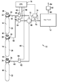
도 1은 기재에 탄소를 주입하기 위하여 탄소 도판트 소스 물질을 이온 주입기로 공급하는 본 발명에 따른 작업 모드를 예시하는 이온 주입 시스템의 개략도이다.
도 2는 50mA의 소스 빔 전류에서 NF3 동축류 속도(표준 입방센티미터/분(sccm))의 함수로서 플롯팅된 탄소 도판트 물질 빔 전류(C+ 빔, 밀리암페어)의 그래프이다.
도 3은 30mA의 소스 빔 전류에서 NF3 동축류 속도(표준 입방센티미터/분(sccm))의 함수로서 플롯팅된 탄소 도판트 물질 빔 전류(C+ 빔, 밀리암페어)의 그래프이다.BRIEF DESCRIPTION OF THE DRAWINGS Figure 1 is a schematic view of an ion implantation system illustrating a working mode according to the present invention for supplying a carbon dopant source material to an ion implanter for implanting carbon into a substrate;
2 is a graph of carbon dopant material beam current (C + beam, milliamperes) plotted as a function of NF 3 coaxial flow rate (standard cubic centimeter per minute (sccm)) at a source beam current of 50 mA.
3 is a graph of carbon dopant material beam current (C + beam, milliamperes) plotted as a function of NF 3 coaxial flow rate (standard cubic centimeter per minute (sccm)) at a source beam current of 30 mA.
본 발명은 탄소 도판트 소스 물질 및 조성물을 포함하는, 기재에 탄소를 주입하기 위한 시스템 및 방법에 관한 것이다.The present invention is directed to a system and method for injecting carbon into a substrate comprising a carbon dopant source material and composition.
상세한 설명 및 첨부된 특허청구범위에서 사용되는 단수형은 문맥상 명백하게 달리 해석되지 않는 한 복수 인용물을 포함한다.The singular forms used in the detailed description and the appended claims include plural references unless the context clearly dictates otherwise.
본원의 화합물의 유기 잔기 및 유기 화합물 자체는 임의의 적합한 유형일 수 있고, 예를 들어 원소 C, H 및 임의적으로는 헤테로원자(예컨대, O, N, Si 등)를 포함할 수 있다. 본 발명의 이러한 잔기 및 유기 화합물은 그 안의 다른 원소와 화학량론적 비의 임의의 적합한 탄소 수, 예를 들어 C1-C12, 또는 그 이상을 가질 수 있다.The organic moieties of the compounds herein and the organic compounds themselves may be of any suitable type and may include, for example, elements C, H and optionally heteroatoms (e.g., O, N, Si, etc.). Such residues and organic compounds of the present invention may have any suitable number of carbon atoms, for example, C 1 -C 12 , or more, in stoichiometric proportions with other elements therein.
본원에 사용되는 탄소 수 범위(예컨대, C1-C12)의 표시는 이러한 범위 내의 구성 탄소 수의 잔기 각각을 포함하여, 언급된 그 범위 내에서 그 사이의 각각의 탄소 수 및 임의의 다른 언급되거나 그 사이에 속하는 탄소 수 값이 포괄되도록 하며, 명시된 탄소 수 범위 내의 더 작은 탄소 수 범위가 본 발명의 영역 내에서 더 작은 탄소 수 범위에 독립적으로 포함될 수 있는 것으로, 또한 특정 탄소 수 또는 수들을 특별히 배제하는 탄소 수의 범위가 본 발명에 포함되는 것으로, 또한 명시된 범위의 탄소 수 한계치중 하나 또는 둘 다를 배제하는 더 작은 범위도 본 발명에 포함되는 것으로 이해된다. 따라서, C1-C12 알킬은 메틸, 에틸, 프로필, 부틸, 펜틸, 헥실, 헵틸, 옥틸, 노닐, 데실, 운데실 및 도데실을 포함하고자 한다(직쇄뿐만 아니라 이러한 유형의 분지된 기 포함). 따라서, 치환기 잔기에 넓게 적용될 수 있는 탄소 수 범위의 표시, 예를 들어 C1-C12는 본 발명의 구체적인 실시양태에서 탄소 수 범위가 치환기 잔기의 더 넓은 규정 내에 속하는 탄소 수 범위를 갖는 잔기의 더 작은 군으로서 추가로 제한될 수 있도록 함을 알아야 한다. 예로서, 탄소 수 범위, 예를 들어 C1-C12 알킬은 더 제한되게 명시되어, 본 발명의 구체적인 실시양태에서 C1-C4 알킬, C2-C8 알킬, C2-C4 알킬, C3-C5 알킬 또는 넓은 탄소 수 범위 내의 임의의 다른 더 작은 범위 같은 더 작은 범위를 포괄할 수 있다.The indication of carbon number ranges (e.g., C 1 -C 12 ) used herein includes each of the constituent carbon number residues within this range, including the number of carbon atoms therebetween and any other mention Or smaller carbon number range within the specified carbon number range can be independently included in the smaller carbon number range within the scope of the present invention and that the specific carbon numbers or numbers It is understood that the range of specifically excluded carbon numbers is included in the present invention and that smaller ranges excluding one or both of the specified carbon number limits are also included in the present invention. Thus, C 1 -C 12 alkyl is intended to include methyl, ethyl, propyl, butyl, pentyl, hexyl, heptyl, octyl, nonyl, decyl, undecyl and dodecyl (including straight chain as well as branched groups of this type) . Thus, indications of a range of carbon numbers that can be broadly applied to substituent moieties, such as C 1 -C 12, are those in which the number of carbon atoms in a specific embodiment of the present invention is within the range of the number of carbon atoms within the broader definition of the substituent moiety But may be further limited as a smaller group. By way of example, a carbon number range, for example C 1 -C 12 alkyl, is more specifically stated, and in a specific embodiment of the present invention, C 1 -C 4 alkyl, C 2 -C 8 alkyl, C 2 -C 4 alkyl , C 3 -C 5 alkyl, or any other smaller range within a broad carbon number range.
본원에 기재되는 다양한 명시 사항 및 예시와 관련하여 구체적인 치환기, 기, 잔기 또는 구조를 배제하는 단서조항 또는 제한에 의해 본 발명의 화합물을 구체적인 실시양태에서 추가로 명시할 수 있다. 그러므로, 본 발명은 제한적으로 한정된 조성물, 예를 들어 Ri가 C1-C12 알킬이나 단 Rj가 실릴인 경우 Ri가 C4 알킬이 아닌 조성물을 고려한다. The compounds of the present invention may be further specified in specific embodiments by citing clauses or restrictions excluding specific substituents, groups, moieties or structures in connection with the various descriptions and examples set forth herein. Therefore, the present invention contemplates a composition with limited definition, for example, where R i is C 1 -C 12 alkyl, but R i is not C 4 alkyl when R j is silyl.
본 발명은 다양한 유형의 탄소 도판트 소스 물질을 사용하는 이온 주입에 관한 것이다. 본 발명은 하기 탄소 도판트 소스 물질의 사용을 고려한다: CO; CO2; CF4; CH4; COF2; CH2O; C2F4H2; C2H6; 화학식 CxFwOyHzClvNu(여기에서, x는 1 이상이고, w는 0 이상이며, y는 0 이상이고, z는 0 이상이며, v는 0 이상이고, u는 0 이상이나, 단 w, y, z, v 및 u중 하나 이상은 0이 아닌 값을 가짐)의 화합물; 탄화수소; 알칸(CH4, C2H6 등); 환상 알칸(이환상 및 삼환상 화합물 포함, C4H8, C5H10 등); 알켄(C2H4, C3H6,...CnH2n); 환상 알켄(C4H6, C5H8, CnH2n -2); 폴리엔(C4H8 등); 환상 폴리엔; 알킨(C2H2, C3H4, CnH2n -2); 환상 알킨; 아렌(C6H6, C10H8 등), 및 이들의 유도체; 부분적으로 또한 완전히 할로겐화된 탄화수소(CH2F2, CF4, C2H2F4, C2H3F3, C6F6 등); 화학식 ROH(여기에서, R은 유기 잔기임)의 알콜(CH3OH, C2H5OH 등); 할로겐화된 알콜(FCH2OH, F2CHCH2OH 등); 알데하이드(CH2O, CH3COH 등); 에터(CH3OCH3 등); 할로겐화된 에터(FCH2OCH2F 등); 에스터(HCOOCH3, CH3COOCH3 등); 할로겐화된 에스터(F2CHCOOCH3 등); 1급 아민(CH3NH2 등); 2급 아민((CH3)2NH 등); 3급 아민((CH3)3N 등); 할로겐화된 아민(CF3NH2, (CFH2)3N 등); N-할로겐화된 아민(CH3NF2, (CFH2)2NF 등); 나이트로(RNO2) 및 나이트로소(RNO) 알킬 및 할로겐화된 알킬 화합물(CH3NO2, CH3NO, FH2CNO); 탄소 원자의 수가 1개인 할라이드(COCl2, CHF3, CH2F2, CH2F2, CH3F, F3C-OH, F2HC-OH 등); 탄소 원자 2개를 함유하는 할라이드(F3C-COH, F2HC-COH, H3C-CH2F, H3C-CHF2, H3C-CF3, H2FC-CFH2 등); 및 다수개의 탄소 원자를 함유하는 할라이드 및 하이드라이드(C6H6, C6H5F, C6H4F2, C6H3F3, C6H2F4, C6HF5 등).The present invention relates to ion implantation using various types of carbon dopant source materials. The present invention contemplates the use of the following carbon dopant source materials: CO; CO 2 ; CF 4; CH 4 ; COF 2 ; CH 2 O; C 2 F 4 H 2 ; C 2 H 6 ; And the formula in the C x F w O y H z Cl v N u (here, x is 1 or more and, w is more than 0, and y is more than 0, and z is 0 or greater, v is 0 and u is zero , Provided that at least one of w, y, z, v and u has a non-zero value; hydrocarbon; Alkane (CH 4, such as C 2 H 6); Cyclic alkanes (including bicyclic and tricyclic compounds, C 4 H 8 , C 5 H 10 and the like); Alkenes (C 2 H 4 , C 3 H 6 , ... C n H 2n ); Cyclic alkenes (C 4 H 6 , C 5 H 8 , C n H 2n- 2 ); Polyenes (such as C 4 H 8 ); Cyclic polyene; Alkyne (C 2 H 2 , C 3 H 4 , C n H 2n -2 ); Cyclic alkyne; Arenes (C 6 H 6 , C 10 H 8, etc.), and derivatives thereof; Partially also fully halogenated hydrocarbons (CH 2 F 2 , CF 4 , C 2 H 2 F 4 , C 2 H 3 F 3 , C 6 F 6, etc.); Formula ROH alcohol (here, R is an organic moiety Im) (CH 3 OH, C 2 H 5 OH , and the like); Halogenated alcohols (FCH 2 OH, F 2 CHCH 2 OH and the like); Aldehyde (CH 2 O, CH 3 COH and the like); Ether (such as CH 3 OCH 3); Halogenated ethers (such as FCH 2 OCH 2 F); Ester (such as HCOOCH 3, CH 3 COOCH 3) ; Halogenated esters (such as F 2 CHCOOCH 3 ); Primary amine (CH 3 NH 2 and the like); Secondary amine ((CH 3) 2 NH, and the like); Tertiary amine ((CH 3) 3 N and the like); Halogenated amines (CF 3 NH 2, (CFH 2) 3 N and the like); N- halogenated amine (CH 3 NF 2, (CFH 2) 2 NF , and the like); Nitro (RNO 2 ) and nitroso (RNO) alkyl and halogenated alkyl compounds (CH 3 NO 2 , CH 3 NO, FH 2 CNO); The number of carbon atoms 1 private halide (COCl 2, CHF 3, CH 2 F 2, CH 2 F 2, CH 3 F, F 3 C-OH, F 2 HC-OH and the like); (F 3 C-COH, F 2 HC-COH, H 3 C-CH 2 F, H 3 C-CHF 2 , H 3 C-CF 3 , H 2 FC-CFH 2, etc.) containing two carbon atoms ); And halides and hydrides containing a plurality of carbon atoms (C 6 H 6 , C 6 H 5 F, C 6 H 4 F 2 , C 6 H 3 F 3 , C 6 H 2 F 4 , C 6 HF 5 , ).
상기 탄소 도판트 소스 물질은 순수한(neat) 형태로, 또는 상이한 탄소 도판트 물질의 혼합물로(예를 들어, 기체 혼합물로서) 사용될 수 있다. 또한, 본 발명은 동축류 기체와 함께 이러한 유형의 탄소 도판트 소스 물질을 사용함을 고려한다. 본 발명의 탄소 도판트 소스 물질과 함께 사용되는 이러한 동축류 기체는 하이드라이드, 플루오라이드, 불활성 기체, 옥사이드 기체 및 다른 기체를 포함한다.The carbon dopant source material may be used in neat form or as a mixture of different carbon dopant materials (e.g., as a gaseous mixture). The present invention also contemplates the use of this type of carbon dopant source material in conjunction with coaxial gas. These coaxial gases used with the carbon dopant source material of the present invention include hydrides, fluorides, inert gases, oxide gases and other gases.
다양한 실시양태에서, 탄소 도판트 소스 물질은 하나 이상의 동축류 기체와 함께 이온 주입기로 유동되거나 또는 하나 이상의 추가적인 기체와의 혼합물로 이온 주입기로 유동되며, 이 때 상기 하나 이상의 동축류 기체 또는 하나 이상의 추가적인 기체는 H2, PH3, AsH3, CH4, GeH4, SiH4, NH3, N2F4, F2, XeF2, BF3, SF6, GeF4, SiF4, NF3, HF, WF6, MoF6, Ar, Ne, Kr, Xe, He, N2, O2, O3, H2O2, H2O, Cl2, HCl, COF2, CH2O, C2F4H2, PF3, PF5, CF4, CF3H, CF2H2, CFH3, B2F4, 화학식 XyFz(여기에서, X는 F와 화학량론적 비의 임의의 원소이고, y≥1, z≥1임)의 화합물, 화학식 CaOxHyFz(여기에서, a≥0, x≥0, y≥0 및 z≥1임)의 화합물, 화학식 CxFyHz(여기에서, x≥0, y>0, z≥0임)의 화합물, 및 플루오르-함유 기체로 이루어진 군으로부터 선택된다.In various embodiments, the carbon dopant source material flows into the ion implanter with one or more coaxial flow gases or flows into the ion implanter in a mixture with one or more additional gases, wherein the one or more coaxial flow gases or one or more additional gas is H 2, PH 3, AsH 3 ,
예시적인 동축류 하이드라이드 기체는 H2, PH3, AsH3, CH4, GeH4, SiH4 및 NH3를 포함한다.Exemplary co-axial hydride gases include H 2 , PH 3 , AsH 3 , CH 4 , GeH 4 , SiH 4, and NH 3 .
본 발명의 탄소 도판트 소스 물질과 함께 유용한 예시적인 동축류 플루오라이드 기체는 F2, XeF2, BF3, SF6, GeF4, SiF4, NF3, HF, WF6, 및 MoF6를 포함한다.Useful exemplary Coflow fluoride gas with the carbon dopant source material of the present invention include F 2, XeF 2, BF 3 ,
본 발명의 탄소 도판트 소스 물질과 함께 동축류 성분으로서 사용될 수 있는 불활성 기체는 Ar, Ne, Kr, Xe, 및 He를 포함한다.Inert gases that can be used as coaxial components with the carbon dopant source material of the present invention include Ar, Ne, Kr, Xe, and He.
탄소 도판트 소스 물질과 함께 유용한 옥사이드 기체 동축류 성분은 O2, O3, H2O2, 및 H2O를 포함한다.Useful carbon dopant oxide gas Coflow component with the source materials include O 2, O 3, H 2
본 발명의 탄소 도판트 소스 물질을 사용함에 있어서 동축류 기체로서 사용될 수 있는 다른 기체는 Cl2, F2, N2 및 HCl을 포함한다.Other gases that may be used as the coaxial gas in the use of the carbon dopant source material of the present invention include Cl 2 , F 2 , N 2, and HCl.
하나의 실시양태에서는, 일산화탄소(CO)가 하이드라이드(예를 들어, H2, PH3, AsH3, CH4, GeH4, SiH4); 플루오라이드 기체(예를 들어, F2, XeF2, BF3, SF6, GeF4, CF4, SiF4); 불활성 기체(예를 들어, Ar, Kr, Xe, He); 옥사이드 기체(예를 들어, O2, O3, H2O2, 및 H2O); 및/또는 Cl2, COF2, CH2O, 또는 C2F4H2 같은 다른 기체 등과 혼합물일 수 있거나 또는 이들과 같은 동축류 기체와 함께 유동될 수 있는 탄소 도판트 소스 기체로서 사용된다. 이러한 혼합물 또는 동축류 배열에서는, 상기 기체중 다수개의 기체를 다양한 혼합물로 또는 동축류 비로 CO와 함께 사용하여 이온 주입 작업에서 목적하는 성능을 달성할 수 있다.In one embodiment, carbon monoxide (CO) are
다른 양태에서, 본 발명은 하이드라이드(H2, PH3, AsH3, CH4, GeH4, SiH4); 플루오라이드 기체(F2, XeF2, BF3, SF6, GeF4, CF4, SiF4); 불활성 기체(Ar, Kr, Xe, He); Cl2, COF2, CH2O, C2F4H2, PF3, PF5 또는 다른 플루오르-함유 기체 같은 다른 기체와의 혼합물로서 또는 이들 기체와의 동축류로서의 탄소 도판트 기체(예컨대, CF4, CH4, COF2, CH2O 또는 C2F4H2)의 용도에 관한 것이다. 동축류 기체가 상기 기체중 다수개를 상이한 동축류 비로 포함할 수 있거나, 또는 탄소 도판트 기체를 다성분 기체 혼합물중 다수개의 성분과 함께 사용할 수 있는데, 기체 성분의 상대적인 비는 이온 주입 작업에서 목적하거나 필요한 결과를 달성하도록 적절하게 변화될 수 있다.In another aspect, the present invention provides a process for preparing a compound of formula (I), wherein the hydride (H 2 , PH 3 , AsH 3 , CH 4 , GeH 4 , SiH 4 ); Fluoride gases (F 2 , XeF 2 , BF 3 , SF 6 , GeF 4 , CF 4 , SiF 4 ); Inert gases (Ar, Kr, Xe, He); As a mixture with other gases such as Cl 2 , COF 2 , CH 2 O, C 2 F 4 H 2 , PF 3 , PF 5 or other fluorine-containing gases or carbon dioctate gases as co- CF 4 , CH 4 , COF 2 , CH 2 O or C 2 F 4 H 2 ). A coaxial gas may contain a plurality of the gases in different coaxial ratios or a carbon dopant gas may be used with a plurality of components in a multicomponent gas mixture wherein the relative proportions of the gaseous components Or may be suitably varied to achieve the required result.
다른 양태에서, 본 발명은 하기 기체를 포함하는 구체적인 기체 혼합물 또는 동축류 배열을 고려한다:In another aspect, the present invention contemplates a specific gas mixture or coaxial arrangement comprising:

상기 식에서, x 및 y는 임의의 적절한 화학량론적 값이다.Where x and y are any suitable stoichiometric values.
기체 혼합물뿐만 아니라 동축류 기체 성분을 포함하는 상기 탄소 도판트 소스 조성물을 이온 주입 작업에 사용하여 상응하는 제품을 생성시키기 위해 다양한 기재에 주입할 수 있다. 예를 들어, 본 발명에 따라 탄소가 주입되는 기재는 반도체 제품, 평면 패널 디스플레이 제품, LED 제품 또는 태양 전지판 제품을 제조하기 위한 반도체를 포함할 수 있다. 이러한 제품은 구성요소, 반조립품 또는 최종 제품의 구조적 일부일 수 있다.The carbon dopant source composition comprising a gas mixture as well as a co-axial gas component can be used in an ion implantation operation to implant various substrates to produce a corresponding product. For example, a substrate into which carbon is implanted according to the present invention may include a semiconductor product, a flat panel display product, a LED product, or a semiconductor for manufacturing a solar panel product. Such a product can be a structural part of a component, a semi-assembly or an end product.
본 발명은 이온 주입 시스템에서 이온 소스의 목적하는 소스 수명을 제공하기 위하여 또는 다르게는 이온 주입기의 성능을 개선하기 위하여 변화될 수 있는 농도 및 부피 유속에서의 조합된 탄소 도판트 기체 물질의 용도를 고려한다.The present invention contemplates the use of a combined carbon dopant gaseous substance at a concentration and volume flow rate that may be varied to provide the desired source lifetime of the ion source in an ion implantation system or otherwise to improve the performance of the implanter do.
다른 양태에서, 본 발명은 소량의 세정 기체를 탄소 도판트 소스 물질과 혼합하여 이온 소스에서 세정 및 텅스텐의 텅스텐 필라멘트로의 복귀를 수행하고, 시스템의 침착물과의 반응에 의해 휘발성 플루오라이드 또는 다른 휘발성 물질을 형성시킴으로써, 이러한 휘발된 침착물을 시스템 밖으로 펌핑할 수 있도록 함을 고려한다. 세정 기체는 임의의 적합한 유형일 수 있고, 예를 들어 플루오르 또는 COF2, 또는 임의의 다른 산소-함유 기체, 또는 임의의 다른 플루오르-함유 기체를 포함할 수 있으며, 임의적으로는 세정 기체를 이온 주입기로 수송하기 위한 담체 매질로서 불활성 기체를 사용할 수 있다.In another aspect, the present invention relates to a method of cleaning a tungsten filament, comprising the steps of mixing a small amount of a cleaning gas with a carbon dopant source material to effect cleaning from an ion source and return of the tungsten to the tungsten filament, By forming a volatile material, it is considered that such volatilized deposits can be pumped out of the system. The cleaning gas may be of any suitable type and may include, for example, fluorine or COF 2 , or any other oxygen-containing gas, or any other fluorine-containing gas, and optionally a cleaning gas may be introduced into the ionizer An inert gas may be used as the carrier medium for transport.
동일 반응계 내 세정 기체의 사용은 이온 주입기의 성능을 현저히 개선시켜, 고장 사이의 평균 시간(MTBF)을 연장시키고, 이온 주입기 시스템의 가동 시간을 개선하고 가동 중지 시간을 감소시킨다.The use of cleaning gas in the in situ system significantly improves the performance of the ion implanter, extending the mean time between failures (MTBF), improving the uptime of the ion implanter system and reducing downtime.
본 발명은 또한 다성분 도판트 소스 물질중에 상기 기재된 기체 같은 탄소 도판트 소스 기체, 또는 이러한 탄소 도판트 소스 기체 또는 기체들을 함유하는 혼합물을 사용하는 클러스터 또는 분자 주입을 고려한다. 탄소 이온(Cx +, 여기에서 x는 1보다 큼)만을 사용하여 클러스터 또는 분자 주입을 수행할 수 있다. 또한 화학식 CxFwOyHzClvNu +(여기에서, x는 1 이상이고, w, y, z, v 및 u 각각의 값은 0 이상이지만, 적어도 하나는 0이 아님)의 이온을 사용하여 클러스터 또는 분자 주입을 수행할 수 있다. 또 다른 실시양태에서는, C6H6 +를 사용하여 클러스터 주입을 수행할 수 있다. The present invention also contemplates clustering or molecular injection using a gaseous carbon-like dopant source gas as described above, or a mixture containing such carbon dopant source gases or gases, in the multicomponent dopant source material. Clusters or molecular implants can be performed using only carbon ions (C x + , where x is greater than 1). Also provided is a compound of the formula C x F w O y H z Cl v N u + wherein x is greater than or equal to 1 and each value of w, y, z, v, and u is greater than or equal to 0, Clones or molecular implants can be performed using ions. In another embodiment, C 6 H 6 + can be used to perform cluster implantation.
이제 도면을 참조하면, 도 1은 본 발명의 한 실행에 따른 기재의 탄소 도핑에 적합화된 이온 주입 시스템의 개략도이다. Referring now to the drawings, Figure 1 is a schematic diagram of an ion implantation system adapted for carbon doping of a substrate in accordance with an embodiment of the invention.
도 1에 도시된 바와 같이, 주입 시스템(10)은 도판트 소스 기체를 주입기에 전달하기 위하여 도판트 기체 소스(14, 16, 18)에 수용 관계로 배열된 이온 주입기(12)를 포함한다.As shown in FIG. 1, the
탄소 도판트 기체 소스(14)는 탄소 도판트 소스 기체를 함유하는 용기를 포함한다. 용기는 탄소 도판트 소스 기체 공급 라인(44)에 연결된 방출 포트(24)를 갖는 밸브 헤드 어셈블리(22)를 포함한다. 밸브 헤드 어셈블리(22)에는 밸브 헤드 어셈블리의 밸브를 수작업으로 조정하기 위한 핸드 휠(38)이 장치되어, 밸브를 목적하는 바와 같이 완전 개방 위치와 완전 폐쇄 위치 사이에서 바꿈으로써 용기(20)에 함유된 기체를 분배하거나 또는 다르게는 폐쇄 상태로 저장한다.The carbon
동축류 기체는 또한 각각 소스(14)와 유사한 방식으로 구성된 동축류 소스(16, 18)에 함유된다. 동축류 소스(16)는 핸드 휠(40)이 연결된 밸브 헤드 어셈블리(28)가 장치된 용기(26)를 포함한다. 밸브 헤드 어셈블리(28)는 동축류 기체 공급 라인(52)이 연결된 방출 포트(30)를 포함한다.Coaxial gas is also contained in the coaxial
소스(18)는 밸브 헤드 어셈블리(34)의 밸브를 작동시키기 위한 핸드 휠(42)이 연결된 밸브 헤드 어셈블리(34)가 장치된 용기(32)를 포함한다. 밸브 헤드 어셈블리(34)는 또한 동축류 기체 방출 라인(60)에 연결된 방출 포트(36)를 포함한다.The
도시된 배열에서는, 도판트 소스 기체 또는 다수개의 도판트 소스 기체가 공급될 수 있거나, 또는 도판트 기체 또는 기체들과 비-도판트 동축류 기체 또는 기체들이 임의의 목적하는 조합으로 공급될 수 있다. 따라서, 도시된 배열은 3개의 도판트 소스 기체, 또는 다르게는 하나의 도판트 소스 기체와 2개의 동축류 기체, 또는 다르게는 2개의 도판트 소스 기체와 하나의 동축류 기체를 혼합 챔버(68)로 유동시키기 위하여 선택적으로 분배할 수 있다.In the arrangement shown, a dopant source gas or a plurality of dopant source gases may be supplied, or dopant gases or gases and non-dopant coaxial gases or gases may be supplied in any desired combination . Thus, the arrangement shown comprises three dopant source gases, or alternatively one dopant source gas and two coaxial flow gases, or alternatively two dopant source gases and one coaxial flow gas, Lt; RTI ID = 0.0 > flow. ≪ / RTI >
개별적인 소스로부터의 유동을 제어하기 위하여, 개별적인 기체 공급 라인(44, 52, 60)에는 각각 유동 제어 밸브(46, 54, 62)가 제공된다. Individual
유동 제어 밸브(46)에는 작동기를 CPU(78)에 연결하는 신호 전송 라인(50)을 갖는 자동 밸브 작동기(48)가 장치되고, 이에 의해 CPU(78)는 제어 신호를 신호 전송 라인(50)에서 밸브 작동기로 전송하여 밸브(46)의 위치를 조정하고, 따라서 용기(20)에서 혼합 챔버(68)로의 기체의 유동을 제어한다. The
유사한 방식으로, 기체 방출 라인(52)은 밸브 작동기(56)와 연결된 유동 제어 밸브(54)를 함유하고, 상기 밸브 작동기는 다시 신호 전송 라인(58)에 의해 CPU(78)에 연결된다. 상응하게, 기체 방출 라인(60)의 유동 제어 밸브(62)에는 신호 전송 라인(66)에 의해 CPU(78)에 연결된 밸브 작동기(64)가 장치된다.In a similar manner, the
이러한 방식으로, CPU는 상응하는 용기(20, 26, 32)로부터의 개별적인 기체의 유동을 작동가능하게 제어할 수 있다.In this way, the CPU can operatively control the flow of the individual gases from the corresponding
기체가 혼합 챔버(68)로 동시에 유동하는(함께 유동하는) 경우, 생성되는 기체를 이온 주입기(12)로 통과시키기 위하여 공급 라인(70)으로 방출한다. When the gas flows (flows together) into the mixing
상응하게는, 하나의 소스(14, 16 또는 18)만 분배 모드로 작동되는 경우에는, 상응하는 하나의 기체가 연결된 유동 제어 밸브에 의해 조정되는 바와 같이 혼합 챔버를 통해 유동하고, 공급 라인(70)에서 이온 주입기로 통과한다.Correspondingly, when only one
공급 라인(70)에는 공급 라인 및 기체 분석기(74)와 연통되는 우회 라인(72, 76)이 포함된 우회 유동 루프가 연결된다. 따라서, 기체 분석기(74)는 공급 라인(70)의 주류(main flow)로부터의 측류(side stream)를 수용하고, 기체 스트림의 농도, 유속 등과 상관되는 모니터링 신호를 발생시킨 다음 CPU(78)와 분석기(74)를 연결하는 신호 전송 라인에서 모니터링 신호를 전송한다. 이러한 방식으로 CPU(78)는 기체 분석기(74)로부터 모니터링 신호를 수용하고 이를 처리하여 개별적인 밸브 작동기(48, 56, 64) 또는 이들중 선택된 하나 또는 여러개에 적절하게 전송되는 출력 제어 신호를 생성시킴으로써, 이온 주입기로의 기체의 목적하는 분배 작업을 수행한다.The
이온 주입기(12)는 유출물 라인(80)에서 유출물 처리 단위장치(82)로 유동되는 유출물을 생성시키며, 유출물 처리 단위장치는 세척, 촉매에 의한 산화 등을 비롯한 유출물 처리 작업에 의해 유출물을 처리하여, 배출 라인(84)에서 처리 단위장치(82)로부터 방출되고 추가적인 처리 또는 다른 폐기로 통과될 수 있는 처리된 기체 유출물을 생성시킬 수 있다. The
CPU(78)는 임의의 적합한 유형일 수 있고, 범용 프로그래밍 가능한 컴퓨터, 특수 목적의 프로그래밍 가능한 컴퓨터, 프로그래밍 가능한 논리 제어기, 마이크로프로세서, 또는 상기 기재된 바와 같이 모니터링 신호의 신호 처리 및 출력 제어 신호 또는 신호들의 생성에 효과적인 다른 컴퓨터 단위장치를 다양하게 포함할 수 있다.The
그러므로, CPU는 소스(14, 16, 18)중 둘 또는 셋 모두로부터 동시에 유동하는 기체(개별적인 기체는 연속적으로 유동함)를 포함하는 환상 작업을 수행하도록 프로그램에 의해 구성될 수 있다. 따라서, 기체의 동축류 또는 혼합물, 또는 연속적인 기체 유동을 비롯한 임의의 유동 모드가 허용될 수 있다.Thus, the CPU can be programmed to perform annular tasks involving simultaneous flowing of gases from two or all of the
따라서, 이온 주입기에서의 기재의 탄소 도핑은 탄소 도판트 기체를 단독으로 또는 다른 기체 물질과 조합하여 사용하는 임의의 다양한 방식으로 수행될 수 있음을 알게 될 것이다. 그러므로, 도 1에 도시된 이온 주입 시스템 또는 본 발명에 따라 작동하도록 상응하게 구성된 이온 주입 시스템의 다양한 실행에서, 탄소 도판트 기체를 하이드라이드 기체, 플루오라이드 기체, 불활성 기체, 옥사이드 기체 또는 다른 기체와 다양하게 합칠 수 있음을 알게 될 것이다. Thus, it will be appreciated that the carbon doping of the substrate in the ion implanter may be performed in any of a variety of ways, using the carbon dopant gas alone or in combination with other gaseous materials. Therefore, in various implementations of the ion implantation system shown in FIG. 1 or correspondingly configured ion implantation systems to operate in accordance with the present invention, the carbon dopant gas can be implanted with a hydride gas, a fluoride gas, an inert gas, an oxide gas, You will find that they can be combined in various ways.
하나의 실시양태에서는, 이온 주입 작업에 기체의 혼합물을 사용할 수 있다. 예를 들어, 앞서 기재된 기체 물질을 사용하여 다수개(예컨대, 10개 이하, 또는 그 이상)의 탄소 도판트 소스 기체를 사용할 수 있다. In one embodiment, a mixture of gases may be used for the ion implantation operation. For example, a plurality of (e. G., 10 or less, or more) carbon dopant source gases may be used using the gaseous materials described above.
탄소 도판트 소스 기체와 하이드라이드(들), 플루오라이드(들), 불활성 기체(들), 옥사이드 기체(들) 또는 다른 기체(들)의 기체 혼합물을 사용할 수 있는데, 이 때 다양한 실시양태에서 기체 물질의 수는 단일 탄소 도판트 소스 기체의 수 면에서 1개 내지 20개일 수 있다. 다르게는, 다수개의 탄소 도판트 소스 기체를 사용하는 경우에는, 하이드라이드 기체, 플루오라이드 기체, 불활성 기체, 옥사이드 기체 및/또는 기재된 다른 기체로부터 선택되는 추가적인 기체 물질을 수 면에서 20개 이하 또는 그 이상으로 사용할 수 있다. 이러한 다성분 기체 혼합물, 또는 다수개의 기체 물질의 동축류에서, 각각의 기체의 백분율은 다른 기체 물질에 대해 변할 수 있다. 혼합물에서, 예를 들어 혼합물중 각 기체의 백분율은 기체 혼합물중 개별적인 기체의 총 부피에 기초하여 독립적으로 0.001부피% 내지 99.999부피%일 수 있으며, 기체 혼합물중 모든 기체 물질의 부피%는 총 100부피%여야 한다.A carbon mixture of carbon dopant source gas and hydride (s), fluoride (s), inert gas (s), oxide gas (s) or other gas (s) The number of materials may be from 1 to 20 in number of single carbon dopant source gases. Alternatively, where a plurality of carbon dopant source gases are used, it may be desirable to use an additional gaseous substance selected from hydride gas, fluoride gas, inert gas, oxide gas, and / Or more. In such a multicomponent gas mixture, or in a coaxial stream of a plurality of gaseous materials, the percentage of each gas may vary for different gaseous materials. In the mixture, for example, the percentage of each gas in the mixture may be independently from 0.001% by volume to 99.999% by volume based on the total volume of the individual gases in the gas mixture, and the volume percentage of all gaseous materials in the gas mixture is 100% %.
따라서, 본 발명은 (A) 하나 이상의 탄소 도판트 소스 기체(들), 및 (B) 하나 이상의 플루오로 화합물 기체(들), (C) 하나 이상의 불활성 기체, (D) 하나 이상의 옥사이드 기체, 및 (E) 다른 기체(예를 들어, N2, H2 등)로 이루어진 군으로부터 선택되는 하나 이상의 추가적인 기체를 포함하는 기체 조합 조성물을 고려한다. 하나 이상의 탄소 도판트 소스 기체(들)는 본원에 개시된 탄소 도판트 소스 기체(들)중 임의의 것을 포함할 수 있다.Accordingly, the present invention relates to a process for the preparation of (a) at least one carbon dopant source gas (s), and (B) at least one fluorocompound gas (s), (C) at least one inert gas, (D) (E) at least one additional gas selected from the group consisting of other gases (e.g., N 2 , H 2, etc.). The one or more carbon dopant source gas (s) may include any of the carbon dopant source gas (s) disclosed herein.
구체적인 실시양태에서, 기체 조합 조성물은 (A) 하나 이상의 탄소 도판트 소스 기체(들), 및 (B) 하나 이상의 플루오로 화합물 기체(들)를 포함하며, 이 때 상기 탄소 도판트 소스 기체(들)(A)는 CO, CO2, COF2 및 CaOxHyFz(여기에서, a≥1, x≥0, y≥0 및 z≥1임)로 이루어진 군으로부터 선택되고, 상기 플루오로 화합물 기체(들)(B)는 F2, COF2, CF4, MoF6, B2F4, NF3, N2F4, XeF2, BF3, SF6, GeF4, SiF4, WF6, 및 화학식 XyFz(여기에서, X는 F와 화학량론적인 비의 임의의 원소이고, y≥1, z≥1임)의 화합물, 화학식 CaOxHyFz(여기에서, a≥0, x≥0, y≥0 및 z≥1임)의 화합물, 및 화학식 CxFyHz(여기에서, x≥0, y>0, z≥0임)의 화합물, 예를 들어 CF4, CF3H, CF2H2, CFH3 등과 같은 화합물로 이루어진 군으로부터 선택된다. 이러한 기체 조합 조성물에서, 탄소 및 플루오르 원자를 둘 다 함유하는 기체는 군 (A) 및/또는 군 (B)에 존재할 수 있다.In a specific embodiment, the gas combining composition comprises (A) at least one carbon dopant source gas (s), and (B) at least one fluorocompound gas (s), wherein the carbon dopant source gas (A) is selected from the group consisting of CO, CO 2 , COF 2 and C a O x H y F z (where a? 1, x? 0, y? 0 and z ? 1) compound gas fluoro (s) (B) is F 2, COF 2, CF 4 ,
다른 양태에서 본 발명은 플루오로 화합물 기체(들)의 부재하에서의 상응하는 탄소 도핑에 비해 이온 주입기의 성능이 개선된, 기재, 예를 들어 반도체, 태양 전지판, LED 또는 평면 패널 기재의 탄소 도핑에 유용한, 하나 이상의 탄소 도판트 소스 기체(들) 및 (B) 하나 이상의 플루오로 화합물 기체(들)를 포함하는 기체 조합 조성물에 관한 것이다. 예를 들어, 플루오로 화합물 기체(들)는 더 높은 빔 전류, 이온 주입기 내에 침착된 잔류물의 감소된 양, 감소된 고장 사이의 평균 시간, 요구되는 유지 작업의 감소된 수준 등을 야기할 수 있다.In another aspect, the invention is useful for carbon doping of substrates, e.g., semiconductors, solar panels, LEDs or flat panel substrates, with improved performance of the implanter relative to the corresponding carbon doping in the absence of the fluoro compound gas , At least one carbon dopant source gas (s), and (B) at least one fluorocompound gas (s). For example, the fluorocompound gas (s) may cause higher beam currents, a reduced amount of residue deposited in the implanter, an average time between reduced failures, a reduced level of required maintenance operations, etc. .
이러한 기체 조합 조성물에서, 탄소 도판트 소스 기체(들)(A)는 CO, CO2, CF4, COF2 및 CaOxHyFz(여기에서, a≥1, x≥0, y≥0 및 z≥0임)로 이루어진 군으로부터 선택되고, 상기 플루오로 화합물 기체(들)(B)는 F2, COF2, CF4, MoF6, B2F4, NF3, N2F4, XeF2, BF3, SF6, GeF4, SiF4, WF6, 및 화학식 XyFz(여기에서, X는 F와 화학량론적인 비의 임의의 원소이고, y≥1, z≥1임)의 화합물, 화학식 CaOxHyFz(여기에서, a≥0, x≥0, y≥0 및 z≥1임)의 화합물(예를 들어, CF4 또는 COF2), 및 화학식 CxFyHz(여기에서, x≥0, y>0, z≥0임)의 화합물(예를 들어, CF4, CF3H, CF2H2, CFH3)로 이루어진 군으로부터 선택된다. 이러한 기체 조합 조성물에서, 둘 이상의 상이한 기체 물질이 조성물에 존재한다면 탄소 및 플루오르 원자를 둘 다 함유하는 기체는 군 (A) 및/또는 군 (B)에 존재할 수 있다.In such a gas combining composition, the carbon dopant source gas (s) (A) is selected from the group consisting of CO, CO 2 , CF 4 , COF 2 and C a O x H y F z where a≥1, (B) is selected from the group consisting of F 2 , COF 2 , CF 4 , MoF 6 , B 2 F 4 , NF 3 , N 2 F 4, XeF 2, BF 3, SF 6,
다양한 구체적인 실시양태에서 기체 조합 조성물은 군 (A)로부터 하나 이상 10개 이하의 기체, 및 군 (B)로부터 하나 이상 10개 이하의 기체를 포함할 수 있다.In various specific embodiments, the gas combining composition may comprise one or more than ten gases from group (A) and one or more than ten gases from group (B).
기체 조합 조성물은 군 (A) 및 군 (B)의 개별적인 기체의 기체 혼합물 형태일 수 있거나, 또는 개별적인 기체는 서로 동축류 관계에 있을 수 있다. 본원에 사용되는 용어 "동축류 관계"는 군 (A) 기체(들)가 군 (B) 기체(들)와 동시에 동일한 이온 주입기로 유동하고 상기 유동의 적어도 일부가 서로 분리됨(예를 들어, 분리 유동 통과)을 의미한다. 그러므로, 군 (A) 및 군 (B) 기체는 군 (A) 및 군 (B) 기체를 함유하는 통상적인 공급 용기에서 초기 혼합된 형태일 수 있다. 다르게는, 군 (A) 기체(들)는 군 (B) 기체(들)의 공급 라인(들)에 대해 이온 주입기로의 별도의 공급 라인(들)에 있을 수 있다. 또 다르게는, 군 (A) 기체(들)의 공급 라인(들) 및 군 (B) 기체(들)의 공급 라인(들)이 이온 주입기 앞쪽의 유동 통로에서 종결되어, 기체가 유동 통로에서 함께 혼합되고 생성된 기체 혼합물이 이들 유동 통로로부터 이온 주입기에 들어가게 함으로써, 개별적인 군 (A) 및 군 (B) 기체 유동이 이온 주입기로의 유동의 일부동안 서로 분리되고, 이온 주입기로의 유동의 다른 일부 동안 서로 혼합되도록 할 수 있다.The gas combining composition may be in the form of a gas mixture of the individual gases of group (A) and group (B), or the individual gases may be in a coaxial relationship with one another. As used herein, the term "coaxial relationship" means that the group (A) gas (s) flow into the same ion implanter at the same time as the group (B) gas (s) and at least a portion of the flow is separated Flow through). Therefore, group A and group B gases may be in an initial mixed form in conventional supply vessels containing group A and group B gases. Alternatively, the group (A) gas (s) may be in a separate supply line (s) to the ion implanter for the supply line (s) of the group (B) gas (s). Alternatively, the supply line (s) of the supply (s) and (B) gas (s) of the group (A) gas (s) terminate in the flow path in front of the ion implanter, By allowing the mixed and produced gas mixture to enter the ion implanter from these flow passages, the individual group A and group (B) gas flows are separated from each other during a portion of the flow to the ion implanter, and another part of the flow to the ion implanter To be mixed with each other.
군 (A) 기체(들) 대 군 (B) 기체(들)의 상대적인 비와 관련하여, 군 (A) 기체(들) 및 군 (B) 기체(들)은 각각 군 (A) 기체와 군 (B) 기체의 총 부피에 기초하여 0.001부피% 내지 99.999부피%일 수 있으며, 조성물중 군 (A) 기체와 군 (B) 기체의 부피 백분율은 총 100부피%이다.With respect to the relative ratio of group (A) gas (s) to group (B) gas (s), group (A) gas (s) and group (B) from 0.001% to 99.999% by volume based on the total volume of the gas, wherein the volume percentages of group (A) gas and group (B) gases in the composition are 100% by volume total.
하나의 실시양태에서, 군 (A) 기체와 군 (B) 기체의 조합 조성물중 군 (B) 기체(들)의 상대적인 비는 군 (A) 기체와 군 (B) 기체의 총 부피에 기초하여 0.001부피% 내지 20부피%이다.In one embodiment, the relative ratio of group (B) gas (s) in the combination composition of group (A) gas and group (B) gas is based on the total volume of group (A) 0.001% by volume to 20% by volume.
다른 실시양태에서, 군 (A) 탄소 도판트 소스 기체와 조합되는 군 (B) 플루오로 화합물로서의 NF3의 사용은 기체 조합 조성물의 총 부피를 기준으로 하여 0.5 내지 15부피%, 더욱 바람직하게는 0.5 내지 10부피% 정도의 NF3 농도에서 이온 주입기의 빔 전류 면에서 상당한 개선을 제공하는 것으로 입증되었다.In another embodiment, the use of NF 3 as the fluorocompound of group (B) in combination with group (A) carbon dopant source gas is from 0.5 to 15% by volume, based on the total volume of the gas combining composition, Has been demonstrated to provide significant improvements in terms of beam current in the implanter at an NF 3 concentration of about 0.5 to 10% by volume.
그러므로, 본 발명은 탄소 도판트 소스 기체(들)(A)가 CO, CO2, CF4, COF2 및 CaOxHyFz(여기에서, a≥1, x≥0, y≥0 및 z≥1임)로 이루어진 군으로부터 선택되고, 플루오로 화합물 기체(들)(B)가 F2, COF2, CF4, MoF6, B2F4, NF3, XeF2, BF3, SF6, GeF4, SiF4, WF6, 및 화학식 XyFz(여기에서, X는 F와 화학량론적인 비의 임의의 원소이고, y≥1, z≥1임)의 화합물, 화학식 CaOxHyFz(여기에서, a≥0, x≥0, y≥0 및 z≥1임)의 화합물, 및 화학식 CxFyHz(여기에서, x≥0, y>0, z≥0임)의 화합물로 이루어진 군으로부터 선택되는, (A) 하나 이상의 탄소 도판트 소스 기체(들) 및 (B) 하나 이상의 플루오로 화합물 기체(들)를 포함하는 기체 조합 조성물을 고려한다. 이러한 기체 조합 조성물에서, 탄소 및 플루오르 원자를 둘 다 함유하는 기체는 군 (A) 및/또는 군 (B)에 속할 수 있다.Therefore, the present invention is based on the discovery that the carbon dopant source gas (s) A is CO, CO 2 , CF 4 , COF 2 and C a O x H y F z , where a≥1, x≥0, y≥ 0 and z? 1), and the fluoro compound gas (s) (B) is selected from the group consisting of F 2 , COF 2 , CF 4 , MoF 6 , B 2 F 4 , NF 3 , XeF 2 , BF 3 , SF 6 , GeF 4 , SiF 4 , WF 6 , and a compound of the formula X y F z , wherein X is any element of a stoichiometric ratio with F, y? 1 , z ? C a O x H y F z in the compound, and the formula C x F y H z (here of (here, a≥0, x≥0, y≥0 and z≥1 Im), x≥0, y> (A) one or more carbon dopant source gas (s) and (B) at least one fluorocompound gas (s) selected from the group consisting of compounds of formula do. In such gas combining compositions, the gas containing both carbon and fluorine atoms may belong to group (A) and / or group (B).
기체 조합 조성물의 다양한 구체적인 실시양태에서는, 하나 이상 10개 이하의 군 (B)로부터의 기체와 조합된 하나 이상 10개 이하의 군 (A)로부터의 기체가 존재할 수 있다. 기체 조합 조성물은 군 (A) 기체(들) 및 군 (B) 기체(들) 각각이 군 (A) 및 군 (B) 기체의 총 부피에 기초하여 0.001부피% 내지 99.999부피%의 농도를 갖도록 다양한 실시양태로 구성될 수 있으며, 이 때 조성물중 모든 군 (A) 및 군 (B) 기체의 부피 백분율은 총 100부피%이다. 구체적인 실시양태에서, 군 (A) 기체와 군 (B) 기체의 조합 조성물중 군 (B) 기체(들)의 상대적인 비는 군 (A) 및 군 (B) 기체의 총 부피에 기초하여 0.001 내지 20부피%이며, 이 때 조성물중 군 (A) 기체 및 군 B) 기체 모두의 부피 백분율은 총 100부피%이다. 하나의 실시양태에서, 군 (B) 기체는 NF3를 포함한다. 이러한 NF3는 군 (A) 및 군 (B) 기체의 총 부피에 기초하여 약 0.5 내지 15부피%, 더욱 바람직하게는 0.5 내지 10부피%의 농도로 존재할 수 있으며, 여기에서 조성물중 모든 군 (A) 및 군 (B) 기체의 부피 백분율은 총 100부피%이다. In various specific embodiments of the gas combining composition, there may be a gas from one to more than ten groups (A) in combination with a gas from one or more than ten groups (B). The gas combining composition is prepared so that each of group (A) gas (s) and group (B) gas (s) has a concentration of from 0.001% to 99.999% by volume based on the total volume of group (A) , Wherein the volume percentages of all group (A) and group (B) gases in the composition are 100 volume percent total. In a specific embodiment, the relative ratio of group (B) gas (s) in the combination composition of group (A) gas to group (B) gas is from 0.001 to 10, based on the total volume of group (A) 20 vol.%, Wherein the volume percentages of both group (A) gas and group B) gases in the composition are 100 vol.% Total. In one embodiment, the group (B) gas comprises NF 3 . Such NF 3 may be present at a concentration of from about 0.5 to 15% by volume, more preferably from 0.5 to 10% by volume, based on the total volume of group (A) and group (B) gases, A) and group (B) gases have a total volume percentage of 100% by volume.
추가적인 실시양태에서 본 발명은 본원에 기재된 기체 조합 조성물을 사용하여 기재를 탄소 도핑함을 포함하는, 기재에 탄소 이온을 주입하는 방법에 관한 것이다. 이러한 방법의 기재는 임의의 적합한 유형일 수 있다. 다양한 구체적인 실시양태에서, 기재는 미소전자 기재, 광전자 기재, 광학 기재, 초전도성 기재, 반전도성 기재, 광기전 기재 또는 다른 유형의 기재를 포함할 수 있다. 다른 구체적인 실시양태에서, 기재는 반도체 기재, 태양 전지판 기재, LED 기재 및 평면 패널 기재로부터 선택되는 기재를 포함할 수 있다.In a further embodiment, the invention is directed to a method of injecting carbon ions into a substrate comprising carbon doping the substrate using the gas combining composition described herein. The description of this method may be of any suitable type. In various specific embodiments, the substrate may include a microelectronic substrate, an optoelectronic substrate, an optical substrate, a superconducting substrate, a reverse conducting substrate, a photoconductive substrate, or other types of substrates. In another specific embodiment, the substrate may comprise a substrate selected from a semiconductor substrate, a solar panel substrate, an LED substrate, and a flat panel substrate.
본 발명의 추가적인 양태는, F2, COF2, CF4, MoF6, B2F4, NF3, N2F4, XeF2, BF3, SF6, GeF4, SiF4, WF6, 및 화학식 XyFz(여기에서, X는 F와 화학량론적인 비의 임의의 원소이고, y≥1, z≥1임)의 화합물, 화학식 CaOxHyFz(여기에서, a≥0, x≥0, y≥0 및 z≥1임)의 화합물, 및 화학식 CxFyHz(여기에서, x≥0, y>0, z≥0임)의 화합물로 이루어진 군으로부터 선택되는 하나 이상의 플루오로 화합물 기체(들)와 혼합되고/되거나 동축류 관계인 탄소 도판트 소스 물질을 이온 주입 공정에 전달하는, 탄소 이온 주입 공정에서 빔 전류를 개선하는 방법에 관한 것이다.Additional aspects of the
본 발명의 또 다른 양태는 탄소 도판트 소스 물질을 수용하고, 그로부터 탄소 도판트 물질을 발생시키고, 탄소 도판트 물질을 기재에 주입하도록 구성된 이온 주입기; 및 탄소 도판트 소스 물질을 이온 주입기에 전달하도록 배열된 공급 어셈블리를 포함하는, 이온 주입 시스템에 관한 것이며, 이 때 상기 탄소 도판트 소스 물질은 F2, COF2, CF4, MoF6, B2F4, NF3, N2F4, XeF2, BF3, SF6, GeF4, SiF4, WF6, 화학식 XyFz(여기에서, X는 F와 화학량론적인 비의 임의의 원소이고, y≥1, z≥1임)의 화합물, 화학식 CaOxHyFz(여기에서, a≥0, x≥0, y≥0 및 z≥1임)의 화합물, 및 화학식 CxFyHz(여기에서, x≥0, y>0, z≥0임)의 화합물로 이루어진 군으로부터 선택되는 하나 이상의 플루오로 화합물 기체(들)와 혼합되거나 동축류 관계에 있다. 이러한 시스템의 한 실시양태에서, 탄소 도판트 소스 물질은 CO, CO2, CF4, COF2 및 CaOxHyFz(여기에서, a≥1, x≥0, y≥0 및 z≥0임)로 이루어진 군으로부터 선택되는 하나 이상의 기체(들)를 포함한다. 이러한 시스템의 다른 실시양태에서, 플루오로 화합물 기체는 NF3를 포함한다. 본 발명의 추가적인 실시양태에서, 플루오로 화합물 기체(들)는 CF4 또는 CFH3를 포함한다. 본 발명의 또 다른 실시양태에서, 탄소 도판트 소스 물질은 CO2 또는 COH2를 포함한다.Another aspect of the invention is an ion implanter configured to receive a carbon dopant source material, generate a carbon dopant material therefrom, and inject carbon dopant material into the substrate; And a supply assembly arranged to deliver the carbon dopant source material to the ion implanter, wherein the carbon dopant source material is selected from the group consisting of F 2 , COF 2 , CF 4 , MoF 6 , B 2 F 4, NF 3, N 2 F 4,
하나 이상의 동축류 기체와 함께 이온 주입기로 유동되거나 또는 하나 이상의 추가적인 기체와 혼합되어 이온 주입기로 유동되는 본 발명에 따른 탄소 도판트 소스 물질을 사용하여, 임의의 이러한 동축류 기체 또는 추가적인 기체가 없는 이온 주입기의 상응하는 작동에 비해, 제법 변화, 빔 안정성, 소스 수명, 빔 균일성, 빔 전류 및 소유 비용중 하나 이상의 면에서 이온 주입기의 작동 특징을 향상시킬 수 있다.Using a carbon dopant source material according to the present invention that flows into an ion implanter with one or more coaxial flow gases or is mixed with one or more additional gases and flows into an ion implanter, any such coaxial gas or additional gaseous ions The operating characteristics of the implanter can be improved in terms of at least one of manufacturing variation, beam stability, source lifetime, beam uniformity, beam current and cost of ownership over the corresponding operation of the implanter.
탄소 도판트 소스 기체 또는 동축류 기체의 전달을 위해 본 발명의 실시에서 사용되는 용기는 임의의 적합한 유형일 수 있고, 예를 들어 상응하는 기체를 저장하기 위하여 고체 흡착제 매질을 사용하는 용기를 포함할 수 있으며, 이러한 유형의 기체 용기는 에이티엠아이 인코포레이티드(ATMI, Inc.)(미국 코네티컷주 댄버리)에서 상표명 SDS 및 SAGE로 구입할 수 있다.The container used in the practice of the present invention for delivery of the carbon dopant source gas or coaxial gas may be of any suitable type and may include, for example, a vessel using a solid adsorbent media to store the corresponding gas And gas containers of this type are available from ATMI, Inc. (Danbury, Conn.) Under the trade names SDS and SAGE.
다르게는, 또는 덧붙여서, 본 발명을 실시함에 있어서 탄소 도판트 소스 기체 또는 다른 기체를 전달하기 위해 사용되는 용기는 용기의 내부 부피에 배치되는 하나 이상의 조절기를 갖는 용기를 포함할 수 있으며, 이 때 각 조절기는 용기와 연결된 외부 유동 회로가 설정점 미만의 압력에 있을 때 설정점 압력으로 기체를 분배할 수 있도록 하는 설정점으로 설정된다. 이러한 유형의 용기는 에이티엠아이 인코포레이티드(미국 코네티컷주 댄버리)에서 상표명 VAC로 시판중이다.Alternatively, or in addition, the container used to deliver the carbon dopant source gas or other gas in the practice of the present invention may include a vessel having one or more adjusters disposed in the interior volume of the vessel, The regulator is set to a set point that allows the gas to be distributed to the set point pressure when the external flow circuit connected to the vessel is at a pressure below the set point. This type of container is available from ATMI Inc. (Danbury, Conn.) Under the trade designation VAC.
본 발명의 이온 주입 공정 및 시스템을 이용하여 반도체 제품, 태양 전지판 또는 태양 전지, LED, LED 디스플레이, 평면 패널 디스플레이, 또는 이러한 제품의 구성요소, 반조립품 또는 일부를 제조할 수 있다.The ion implantation process and system of the present invention may be used to manufacture semiconductor products, solar panels or solar cells, LEDs, LED displays, flat panel displays, or components, semi-assemblies or parts thereof.
본 발명에 따라 특정 탄소 도판트 소스 기체를 공급함에 덧붙여, 본 발명은 예를 들어 크립톤 및 수소의 동축류, 또는 담체 매질, 세정 기체 등으로서의 다른 비-도판트 기체의 유동 또는 동축류를 비롯한, 주입 작업과 관련하여 다른 기체의 동축류를 고려한다. In addition to supplying a particular carbon dopant source gas in accordance with the present invention, the present invention can be used in a variety of applications including, but not limited to, the flow or coaxial flow of other non-dopant gases such as, for example, krypton and hydrogen coaxial or carrier media, Consider coaxial flow of other gases in connection with the injection operation.
본원에 기재된 탄소 도판트 소스 기체는 다양한 실시양태에서 동위원소가 풍부한 도판트 소스 기체를 포함할 수 있다.The carbon dopant source gas described herein may include isotopically enriched dopant source gas in various embodiments.
다양한 실시양태에서, 할라이드 세정제를 탄소 도판트 소스 기체에 혼입시켜, 이온 주입기 또는 그의 일부(예컨대, 이온 소스, 빔 라인, 터보펌프, 러핑(roughing) 펌프 등)에서 동일 반응계 내에서 세정 기능을 제공할 수 있다. In various embodiments, a halide detergent is incorporated into a carbon dopant source gas to provide a cleaning function in situ in an ion implanter or a portion thereof (e.g., ion source, beam line, turbo pump, roughing pump, etc.) can do.
본 발명의 이온 주입 방법 및 시스템의 특징 및 이점은 하기 비한정적인 실시예를 참조하여 더욱 충분하게 설명된다.The features and advantages of the ion implantation method and system of the present invention are more fully described with reference to the following non-limiting examples.
실시예Example
IHC 소스를 갖는 이온 주입 소스 시험 스탠드를 사용하여 시험을 수행하였다. 이들 시험에서는, 탄소 도판트 소스 기체로서 일산화탄소(CO)를 사용하였고, 삼플루오르화질소(NF3) 및 이플루오르화제논(XeF2)을 CO와 함께 이온화 챔버로 함께 유동되는 플루오로 물질로서 개별적인 시험 실행에서 별도로 사용하였다. The test was performed using an ion implantation source test stand with an IHC source. In these tests, carbon monoxide (CO) was used as the carbon dopant source gas and nitrogen trifluoride (NF 3 ) and the fluorinating reagent (XeF 2 ) were added to the ionization chamber together with CO as individual fluoro materials It was used separately in the test run.
플루오로 물질로서 NF3를 사용하는 시험에서는, 개별적인 실행시 110V의 아크 전압(ArcV) 및 50mA 및 30mA의 소스 빔 전류에서 이온 주입 탄소 이온(C+) 빔 전류를 결정하였다. CO 유속은 7sccm으로 유지하였다. NF3 동축류 유속을 0 내지 0.48sccm으로 변화시켰다. 시험은 NF3와 CO의 총 유동에 기초하여 NF3 약 3부피% 내지 4부피%에 상응하는 0.2sccm 내지 0.3sccm의 NF3 동축류 유속에서 최대 빔 전류가 달성되었음을 보여주었다. 시험 결과는 각각 탄소 도판트 물질 빔 전류(C+ 빔, mA)가 NF3 동축류 유속(sccm)의 함수로서 플롯팅된 도 2 및 도 3에 도시된다.In tests using NF 3 as the fluoro material, the ion-implanted carbon ion (C +) beam current was determined at an arc voltage (ArcV) of 110 V and a source beam current of 50 mA and 30 mA at a separate run. The CO flow rate was maintained at 7 sccm. The NF 3 coaxial flow rate was varied from 0 to 0.48 sccm. The test showed that the maximum beam current was achieved at an NF 3 coaxial flow rate of 0.2 sccm to 0.3 sccm corresponding to about 3 to 4 vol% of NF 3 based on the total flow of NF 3 and CO. The test results are shown in Figures 2 and 3 where the carbon dopant material beam current (C + beam, mA) was plotted as a function of NF 3 coaxial flow rate (sccm), respectively.
CO 탄소 도판트 소스 기체와 함께 유동되는 XeF2를 사용하여서도 유사한 시험 결과가 수득되었다. Similar test results were obtained using XeF 2 flowing with CO carbon dopant source gas.
그러므로, 본 발명이 특정 실시양태의 설명으로 기재되었으나, 본 발명은 보여진 것들에 대한 다양한 변형, 변화 및 다른 실시양태를 받아들일 수 있음을 알게 될 것이고, 이러한 변화, 변형 및 다른 실시양태는 모두 이후 기재되는 본 발명에 대한 특허청구범위와 관련하여 본원의 개시내용의 넓은 영역 내에 있는 것으로 간주되어야 한다. Therefore, while the present invention has been described in conjunction with the specific embodiments thereof, it will be appreciated that the present invention may be embodied with various changes, modifications, and other embodiments, It should be regarded as being within the broad scope of the disclosure herein with respect to the claims of the invention as set forth.
Claims (37)
상기 탄소 도판트 소스 물질을, H2, PH3, AsH3, CH4, GeH4, SiH4, NH3, N2F4, F2, XeF2, BF3, SF6, GeF4, SiF4, NF3, HF, WF6, MoF6, Ar, Ne, Kr, Xe, He, N2, O2, O3, H2O2, H2O, Cl2, HCl, COF2, CH2O, C2F4H2, PF3, PF5, CF4, CF3H, CF2H2, CFH3, B2F4, 화학식 XyFz(여기에서, X는 F와 화학량론적 비의 임의의 원소이고, y≥1, z≥1임)의 화합물, 화학식 CaOxHyFz(여기에서, a≥0, x≥0, y≥0 및 z≥1임)의 화합물, 화학식 CxFyHz(여기에서, x≥0, y>0, z≥0임)의 화합물, 및 플루오르-함유 기체로 이루어진 군으로부터 선택되는 하나 이상의 동축류 기체와 함께 이온 주입기로 유동시키는 방법.The method according to claim 1,
The carbon dopant source material, H 2, PH 3, AsH 3, CH 4, GeH 4, SiH 4, NH 3, N 2 F 4, F 2, XeF 2, BF 3, SF 6, GeF 4, SiF 4 , NF 3 , HF, WF 6 , MoF 6 , Ar, Ne, Kr, Xe, He, N 2 , O 2 , O 3 , H 2 O 2 , H 2 O, Cl 2 , HCl, COF 2 , CH 2 O, C 2 F 4 H 2, PF 3, PF 5, CF 4, CF 3 H, CF 2 H 2, CFH 3, B 2 F 4, the general formula X y F z (where, X is F and stoichiometric (Where a? 0, x? 0, y? 0, and z ? 1), a compound of the formula C a O x H y F z , With at least one co-axial gas selected from the group consisting of a compound of the formula C x F y H z where x? 0, y> 0, z≥0, and a fluorine-containing gas, Lt; / RTI >
상기 탄소 도판트 소스 물질을, H2, PH3, AsH3, CH4, GeH4, SiH4, NH3, N2F4, F2, XeF2, BF3, SF6, GeF4, SiF4, NF3, HF, WF6, MoF6, Ar, Ne, Kr, Xe, He, N2, O2, O3, H2O2, H2O, Cl2, HCl, COF2, CH2O, C2F4H2, PF3, PF5, CF4, CF3H, CF2H2, CFH3, B2F4, 화학식 XyFz(여기에서, X는 F와 화학량론적 비의 임의의 원소이고, y≥1, z≥1임)의 화합물, 화학식 CaOxHyFz(여기에서, a≥0, x≥0, y≥0 및 z≥1임)의 화합물, 화학식 CxFyHz(여기에서, x≥0, y>0, z≥0임)의 화합물, 및 플루오르-함유 기체로 이루어진 군으로부터 선택되는 하나 이상의 추가적인 기체와의 혼합물로 이온 주입기로 유동시키는 방법.The method according to claim 1,
The carbon dopant source material, H 2, PH 3, AsH 3, CH 4, GeH 4, SiH 4, NH 3, N 2 F 4, F 2, XeF 2, BF 3, SF 6, GeF 4, SiF 4 , NF 3 , HF, WF 6 , MoF 6 , Ar, Ne, Kr, Xe, He, N 2 , O 2 , O 3 , H 2 O 2 , H 2 O, Cl 2 , HCl, COF 2 , CH 2 O, C 2 F 4 H 2, PF 3, PF 5, CF 4, CF 3 H, CF 2 H 2, CFH 3, B 2 F 4, the general formula X y F z (where, X is F and stoichiometric (Where a? 0, x? 0, y? 0, and z ? 1), a compound of the formula C a O x H y F z , , A compound of the formula C x F y H z wherein x≥0, y> 0, z≥0, and a fluorine-containing gas, in combination with at least one additional gas selected from the group consisting of: Lt; / RTI >
상기 탄소 도판트 소스 물질이 CO 또는 CO2를 포함하고; 상기 탄소 도판트 소스 물질을, H2, PH3, AsH3, CH4, GeH4, SiH4, NH3, N2F4, F2, XeF2, BF3, SF6, GeF4, SiF4, NF3, HF, WF6, MoF6, Ar, Ne, Kr, Xe, He, N2, O2, O3, H2O2, H2O, Cl2, HCl, COF2, CH2O, C2F4H2, PF3, PF5, CF4, CF3H, CF2H2, CFH3, B2F4, 화학식 XyFz(여기에서, X는 F와 화학량론적 비의 임의의 원소이고, y≥1, z≥1임)의 화합물, 화학식 CaOxHyFz(여기에서, a≥0, x≥0, y≥0 및 z≥1임)의 화합물, 화학식 CxFyHz(여기에서, x≥0, y>0, z≥0임)의 화합물, 및 플루오르-함유 기체로 이루어진 군으로부터 선택되는 하나 이상의 동축류 기체와 함께 이온 주입기로 유동시키는 방법.The method according to claim 1,
Wherein the carbon dopant source material comprises CO or CO 2 ; The carbon dopant source material, H 2, PH 3, AsH 3, CH 4, GeH 4, SiH 4, NH 3, N 2 F 4, F 2, XeF 2, BF 3, SF 6, GeF 4, SiF 4 , NF 3 , HF, WF 6 , MoF 6 , Ar, Ne, Kr, Xe, He, N 2 , O 2 , O 3 , H 2 O 2 , H 2 O, Cl 2 , HCl, COF 2 , CH 2 O, C 2 F 4 H 2, PF 3, PF 5, CF 4, CF 3 H, CF 2 H 2, CFH 3, B 2 F 4, the general formula X y F z (where, X is F and stoichiometric (Where a? 0, x? 0, y? 0, and z ? 1), a compound of the formula C a O x H y F z , With at least one co-axial gas selected from the group consisting of a compound of the formula C x F y H z where x? 0, y> 0, z≥0, and a fluorine-containing gas, Lt; / RTI >
상기 탄소 도판트 소스 물질이, H2, PH3, AsH3, SF6, CH4, GeH4, SiH4, F2, XeF2, BF3, GeF4, SiF4, Ar, Kr, Xe, He, Cl2, COF2, CH2O, C2F4H2, PF3, PF5, 및 플루오르-함유 기체로 이루어진 군으로부터 선택되는 기체와 혼합되거나 함께 유동하는, CO, CO2, CF4, CH4, COF2, CH2O 및 C2F4H2로 이루어진 군으로부터 선택되는 기체를 포함하는 방법.The method according to claim 1,
Wherein the carbon dopant source material is selected from the group consisting of H 2 , PH 3 , AsH 3 , SF 6 , CH 4 , GeH 4 , SiH 4 , F 2 , XeF 2 , BF 3 , GeF 4 , SiF 4 , CO, CO 2 , CF 3 , and mixtures thereof, which are mixed or together with a gas selected from the group consisting of He, Cl 2 , COF 2 , CH 2 O, C 2 F 4 H 2 , PF 3 , PF 5 , 4 , CH 4 , COF 2 , CH 2 O and C 2 F 4 H 2 .
상기 탄소 도판트 소스 물질을 동축류 기체와 함께 이온 주입기로 유동시키고, 상기 탄소 도판트 소스 물질과 동축류 기체 조합이 하기 조합으로 이루어진 군으로부터 선택되는 방법:

상기 식에서, x 및 y는 임의의 적절한 화학량론적 값을 갖는다.The method according to claim 1,
Wherein the carbon dopant source material is flowed with an ion implanter together with a coaxial flow gas, wherein the carbon dopant source material and the coaxial gas combination are selected from the group consisting of:
In the above formula, x and y have any suitable stoichiometric value.
상기 기재가 반도체 기재, 평면 패널 디스플레이 기재, LED 기재 및 태양 전지판 기재로 이루어진 군으로부터 선택되는 방법.The method according to claim 1,
Wherein the substrate is selected from the group consisting of a semiconductor substrate, a flat panel display substrate, an LED substrate, and a solar panel substrate.
상기 방법이 반도체 제품, 평면 패널 디스플레이 제품, LED 제품, LED 디스플레이 제품 또는 태양 전지판 제품을 제조함에 있어서 수행되는 방법.The method according to claim 1,
Wherein the method is performed in manufacturing a semiconductor product, a flat panel display product, an LED product, an LED display product or a solar panel product.
상기 탄소 도판트 소스 물질을 세정 기체와 혼합하여 이온 주입기로 유동시키는 방법.The method according to claim 1,
Wherein the carbon dopant source material is mixed with a cleaning gas and flows into an ion implanter.
상기 탄소 도판트 소스 물질이 CO를 포함하는 방법.10. The method of claim 9,
Wherein the carbon dopant source material comprises CO.
상기 세정 기체가 플루오르 또는 COF2를 포함하는 방법.9. The method of claim 9,
Wherein the cleaning gas comprises fluorine or COF 2 .
상기 세정 기체가 산소-함유 기체를 포함하는 방법.10. The method of claim 9,
Wherein the cleaning gas comprises an oxygen-containing gas.
상기 세정 기체가 플루오르-함유 기체를 포함하는 방법.10. The method of claim 9,
Wherein the cleaning gas comprises a fluorine-containing gas.
상기 방법이 세정 기체로 이온 주입기를 세정함을 추가로 포함하는 방법.The method according to claim 1,
Wherein the method further comprises cleaning the ion implanter with a cleaning gas.
상기 세정 기체가 플루오르 또는 COF2를 포함하는 방법.15. The method of claim 14,
Wherein the cleaning gas comprises fluorine or COF 2 .
상기 탄소 도판트 소스 물질을 하나 이상의 동축류 기체와 함께 이온 주입기로 유동시키거나 또는 하나 이상의 추가적인 기체와 혼합하여 이온 주입기로 유동시킴으로써, 임의의 상기 동축류 기체 또는 추가적인 기체가 없는 상기 이온 주입기에서의 상응하는 작동에 비해, 제법 변화, 빔 안정성, 소스 수명, 빔 균일성, 빔 전류 및 소유 비용중 하나 이상의 면에서 상기 이온 주입기의 작동 특징을 향상시키는 방법.The method according to claim 1,
The carbon dopant source material is flowed into the ion implanter together with one or more coaxial flow gases or mixed with one or more additional gases to flow to the ion implanter so that any of the coaxial flow gases A method of enhancing the operating characteristics of the ion implanter in terms of at least one of: regime change, beam stability, source lifetime, beam uniformity, beam current, and cost of ownership over a corresponding operation.
상기 기체 조합 조성물이 (A) 하나 이상의 탄소 도판트 소스 기체(들) 및 (B) 하나 이상의 플루오로 화합물 기체(들)를 포함하고, 이 때 상기 탄소 도판트 소스 기체(들)(A)가 CO, CO2, COF2 및 CaOxHyFz(여기에서, a≥1, x≥0, y≥0 및 z≥0임)로 이루어진 군으로부터 선택되고, 상기 플루오로 화합물 기체(들)(B)가 F2, COF2, CF4, MoF6, B2F4, NF3, N2F4, XeF2, BF3, SF6, GeF4, SiF4, WF6, 화학식 XyFz(여기에서, X는 F와 화학량론적 비의 임의의 원소이고, y≥1 및 z≥1임)의 화합물, 화학식 CaOxHyFz(여기에서, a≥0, x≥0, y≥0 및 z≥1임)의 화합물 및 화학식 CxFyHz(여기에서, x≥0, y>0, 및 z≥0임)의 화합물로 이루어진 군으로부터 선택되는 기체 조합 조성물.21. The method of claim 20,
Wherein said gas combining composition comprises (A) at least one carbon dopant source gas (s) and (B) at least one fluorocompound gas (s), wherein said carbon dopant source gas Wherein the fluorine compound gas is selected from the group consisting of CO, CO 2 , COF 2 and C a O x H y F z (where a≥1, x≥0, y≥0 and z≥0) (B) is at least one selected from the group consisting of F 2 , COF 2 , CF 4 , MoF 6 , B 2 F 4 , NF 3 , N 2 F 4 , XeF 2 , BF 3 , SF 6 , GeF 4 , SiF 4 , WF 6 , X y F z , wherein X is any element of F and stoichiometric ratio, y? 1 and z? 1, a compound of the formula C a O x H y F z , x > 0, y > 0 and z > 1) and a compound of the formula C x F y H z wherein x? 0, y> 0, Combination composition.
상기 기체 조합 조성물이 군 (A)로부터의 기체 하나 이상 10개 이하, 및 군 (B)로부터의 기체 하나 이상 10개 이하를 포함하는 기체 조합 조성물.22. The method of claim 21,
Wherein said gas combining composition comprises at least one gas from group (A) and up to at least 10 gases from group (B).
상기 군 (A) 기체(들) 및 군 (B) 기체(들) 각각이 군 (A) 및 군 (B) 기체의 총 부피에 기초하여 0.001부피% 내지 99.999부피%의 농도를 가지며, 이 때 상기 조성물중 모든 군 (A) 기체 및 군 (B) 기체의 부피 백분율이 총 100부피%인 기체 조합 조성물.22. The method of claim 21,
Each of said group (A) gas (s) and group (B) gas (s) has a concentration of from 0.001% to 99.999% by volume based on the total volume of group A and group B gases, Wherein the volume percentages of all groups (A) and (B) gases in the composition are 100 volume percent total.
상기 군 (A) 기체와 군 (B) 기체의 조합 조성물중 군 (B) 기체(들)의 상대적인 비가 군 (A) 및 군 (B) 기체의 총 부피를 기준으로 하여 0.001 내지 20부피%이고, 이 때 상기 조성물중 군 (A) 및 군 (B) 기체 모두의 부피 백분율이 총 100부피%인 기체 조합 조성물.22. The method of claim 21,
The relative ratio of group (B) gas (s) in the combination composition of group (A) gas and group (B) gas is from 0.001 to 20 vol%, based on the total volume of group (A) , Wherein the volume percentages of both group (A) and group (B) gases in the composition are 100 volume% total.
상기 군 (B) 기체(들)가 NF3를 포함하는 기체 조합 조성물.25. The method of claim 24,
Wherein said group (B) gas (s) comprises NF 3 .
상기 NF3가 군 (A) 및 군 (B) 기체의 총 부피에 기초하여 0.5 내지 15부피%의 농도로 존재하며, 이 때 상기 조성물중 군 (A) 및 군 (B) 기체 모두의 부피 백분율이 총 100부피%인 기체 조합 조성물.26. The method of claim 25,
Wherein said NF 3 is present in a concentration of from 0.5 to 15% by volume based on the total volume of group (A) and group (B) gases, wherein the volume percentages of both group (A) Wherein the total composition is 100% by volume.
상기 기재가 반도체 기재, 태양 전지판 기재, LED 기재 또는 평면 패널 기재를 포함하는 방법.28. The method of claim 27,
Wherein the substrate comprises a semiconductor substrate, a solar panel substrate, an LED substrate or a flat panel substrate.
상기 플루오로 화합물 기체(들)가 NF3를 포함하는 방법.30. The method of claim 29,
How the gas compound (s) with the fluoro containing the NF 3.
상기 탄소 도판트 소스 물질이 CO, CO2, COF2 및 CaOxHyFz(여기에서, a≥1, x≥0, y≥0 및 z≥0임)로 이루어진 군으로부터 선택되는 하나 이상의 기체(들)를 포함하는 이온 주입 시스템,32. The method of claim 31,
Wherein the carbon dopant source material is selected from the group consisting of CO, CO 2 , COF 2 and C a O x H y F z wherein a≥1, x≥0, y≥0 and z≥0 An ion implantation system comprising one or more gas (s)
상기 플루오로 화합물 기체(들)가 NF3를 포함하는 이온 주입 시스템.32. The method of claim 31,
Wherein the fluorocompound gas (s) comprises NF 3 .
상기 플루오로 화합물 기체(들)가 CF4를 포함하는 이온 주입 시스템.32. The method of claim 31,
Wherein the fluorocompound gas (s) comprises CF 4 .
상기 플루오로 화합물 기체(들)가 CFH3를 포함하는 이온 주입 시스템.32. The method of claim 31,
Ion implantation systems are compound gas (es) with the fluoro containing the CFH 3.
상기 탄소 도판트 소스 물질이 CO2를 포함하는 이온 주입 시스템.32. The method of claim 31,
Wherein the carbon dopant source material comprises CO 2 .
상기 탄소 도판트 소스 물질이 COF2를 포함하는 이온 주입 시스템.
32. The method of claim 31,
Wherein the carbon dopant source material comprises COF 2 .
Applications Claiming Priority (5)
| Application Number | Priority Date | Filing Date | Title |
|---|---|---|---|
| US201261598817P | 2012-02-14 | 2012-02-14 | |
| US61/598,817 | 2012-02-14 | ||
| US201261625571P | 2012-04-17 | 2012-04-17 | |
| US61/625,571 | 2012-04-17 | ||
| PCT/US2013/025840 WO2013122986A1 (en) | 2012-02-14 | 2013-02-13 | Carbon dopant gas and co-flow for implant beam and source life performance improvement |
Related Child Applications (1)
| Application Number | Title | Priority Date | Filing Date |
|---|---|---|---|
| KR1020207022916A Division KR20200098716A (en) | 2012-02-14 | 2013-02-13 | Carbon dopant gas and co-flow for implant beam and source life performance improvement |
Publications (1)
| Publication Number | Publication Date |
|---|---|
| KR20140133571A true KR20140133571A (en) | 2014-11-19 |
Family
ID=48984641
Family Applications (4)
| Application Number | Title | Priority Date | Filing Date |
|---|---|---|---|
| KR1020227003987A KR20220025123A (en) | 2012-02-14 | 2013-02-13 | Carbon dopant gas and co-flow for implant beam and source life performance |
| KR1020147025467A KR20140133571A (en) | 2012-02-14 | 2013-02-13 | Carbon dopant gas and co-flow for implant beam and source life performance improvement |
| KR1020217017307A KR20210070400A (en) | 2012-02-14 | 2013-02-13 | Carbon dopant gas and co-flow for implant beam and source life performance |
| KR1020207022916A KR20200098716A (en) | 2012-02-14 | 2013-02-13 | Carbon dopant gas and co-flow for implant beam and source life performance improvement |
Family Applications Before (1)
| Application Number | Title | Priority Date | Filing Date |
|---|---|---|---|
| KR1020227003987A KR20220025123A (en) | 2012-02-14 | 2013-02-13 | Carbon dopant gas and co-flow for implant beam and source life performance |
Family Applications After (2)
| Application Number | Title | Priority Date | Filing Date |
|---|---|---|---|
| KR1020217017307A KR20210070400A (en) | 2012-02-14 | 2013-02-13 | Carbon dopant gas and co-flow for implant beam and source life performance |
| KR1020207022916A KR20200098716A (en) | 2012-02-14 | 2013-02-13 | Carbon dopant gas and co-flow for implant beam and source life performance improvement |
Country Status (7)
| Country | Link |
|---|---|
| US (2) | US9960042B2 (en) |
| EP (2) | EP2815424B1 (en) |
| KR (4) | KR20220025123A (en) |
| CN (2) | CN108565198A (en) |
| SG (1) | SG11201404872SA (en) |
| TW (1) | TWI632598B (en) |
| WO (1) | WO2013122986A1 (en) |
Cited By (5)
| Publication number | Priority date | Publication date | Assignee | Title |
|---|---|---|---|---|
| KR20180086230A (en) * | 2015-12-27 | 2018-07-30 | 엔테그리스, 아이엔씨. | A method for improving the performance of an ion-implanted plasma flood gun (PRG) using a small amount of in-system cleaning gas in a sputtering gas mixture |
| KR20180132133A (en) * | 2016-04-11 | 2018-12-11 | 프랙스에어 테크놀로지, 인코포레이티드 | Dopant compositions for ion implantation |
| KR20190056362A (en) * | 2016-09-30 | 2019-05-24 | 액셀리스 테크놀러지스, 인크. | In-situ cleaning using hydrogen peroxide as a secondary gas for the primary dopant or purge gas to minimize carbon deposits at the ion source |
| KR20190085020A (en) * | 2016-11-24 | 2019-07-17 | 액셀리스 테크놀러지스, 인크. | Phosphine co-gas for carbon implants |
| KR20190090384A (en) * | 2016-11-24 | 2019-08-01 | 액셀리스 테크놀러지스, 인크. | Fluorinated phosphorus for carbon implants |
Families Citing this family (12)
| Publication number | Priority date | Publication date | Assignee | Title |
|---|---|---|---|---|
| US7943204B2 (en) * | 2005-08-30 | 2011-05-17 | Advanced Technology Materials, Inc. | Boron ion implantation using alternative fluorinated boron precursors, and formation of large boron hydrides for implantation |
| US20110021011A1 (en) * | 2009-07-23 | 2011-01-27 | Advanced Technology Materials, Inc. | Carbon materials for carbon implantation |
| KR20220025123A (en) * | 2012-02-14 | 2022-03-03 | 엔테그리스, 아이엔씨. | Carbon dopant gas and co-flow for implant beam and source life performance |
| US20130341761A1 (en) | 2012-06-20 | 2013-12-26 | Ashwini K. Sinha | Methods for extending ion source life and improving ion source performance during carbon implantation |
| US8603363B1 (en) | 2012-06-20 | 2013-12-10 | Praxair Technology, Inc. | Compositions for extending ion source life and improving ion source performance during carbon implantation |
| KR102138400B1 (en) * | 2013-03-05 | 2020-07-27 | 엔테그리스, 아이엔씨. | Ion implantation compositions, systems, and methods |
| JP5950855B2 (en) * | 2013-03-19 | 2016-07-13 | 住友重機械イオンテクノロジー株式会社 | Ion implantation apparatus and cleaning method of ion implantation apparatus |
| US10483386B2 (en) * | 2014-01-17 | 2019-11-19 | Taiwan Semiconductor Manufacturing Company, Ltd. | Semiconductor device, transistor having doped seed layer and method of manufacturing the same |
| CN104377122A (en) * | 2014-11-17 | 2015-02-25 | 上海华力微电子有限公司 | Carbon ion injection method |
| CN111492458B (en) | 2017-12-15 | 2024-04-12 | 恩特格里斯公司 | Methods and assemblies for plasma immersion gun (PFG) operation using fluorine-containing and inert gases |
| US11315791B2 (en) | 2018-12-15 | 2022-04-26 | Entegris, Inc. | Fluorine ion implantation method and system |
| WO2021055606A1 (en) * | 2019-09-20 | 2021-03-25 | Entegris, Inc. | Plasma immersion methods for ion implantation |
Family Cites Families (127)
| Publication number | Priority date | Publication date | Assignee | Title |
|---|---|---|---|---|
| US6482262B1 (en) | 1959-10-10 | 2002-11-19 | Asm Microchemistry Oy | Deposition of transition metal carbides |
| US3625749A (en) | 1966-04-06 | 1971-12-07 | Matsushita Electronics Corp | Method for deposition of silicon dioxide films |
| DE1789021C3 (en) | 1967-09-25 | 1975-04-10 | Hitachi, Ltd., Tokio | Zener diode and process for its manufacture |
| JPS4820106B1 (en) | 1968-03-08 | 1973-06-19 | ||
| US3658586A (en) | 1969-04-11 | 1972-04-25 | Rca Corp | Epitaxial silicon on hydrogen magnesium aluminate spinel single crystals |
| US3725749A (en) | 1971-06-30 | 1973-04-03 | Monsanto Co | GaAS{11 {11 {11 P{11 {11 ELECTROLUMINESCENT DEVICE DOPED WITH ISOELECTRONIC IMPURITIES |
| JPS5183473A (en) | 1975-01-20 | 1976-07-22 | Hitachi Ltd | Fujunbutsuno doopinguhoho |
| US4128733A (en) | 1977-12-27 | 1978-12-05 | Hughes Aircraft Company | Multijunction gallium aluminum arsenide-gallium arsenide-germanium solar cell and process for fabricating same |
| JPS588071A (en) | 1981-07-08 | 1983-01-18 | Nippon Iyakuhin Kogyo Kk | Preparation of 2-benzothiazolinone-3-acetic acid amide derivative or its pharmacologically active salt |
| US4459427A (en) | 1981-10-31 | 1984-07-10 | The British Petroleum Company P.L.C. | Process for the conversion of an alkane to a mixture of an alcohol and a ketone |
| JPS60221566A (en) | 1984-04-18 | 1985-11-06 | Agency Of Ind Science & Technol | Thin film forming device |
| US4600801A (en) | 1984-11-02 | 1986-07-15 | Sovonics Solar Systems | Fluorinated, p-doped microcrystalline silicon semiconductor alloy material |
| US4722978A (en) | 1985-08-30 | 1988-02-02 | The B. F. Goodrich Company | Allyl terminated macromolecular monomers of polyethers |
| US4680358A (en) | 1985-11-08 | 1987-07-14 | The B F Goodrich Company | Styryl terminated macromolecular monomers of polyethers |
| JPS6315228A (en) | 1986-07-08 | 1988-01-22 | Asahi Glass Co Ltd | Electrochromic element |
| JPH0772167B2 (en) | 1986-09-04 | 1995-08-02 | サントリー株式会社 | Process for producing 4-amino-3-hydroxybutyric acid derivative |
| US4851255A (en) | 1986-12-29 | 1989-07-25 | Air Products And Chemicals, Inc. | Ion implant using tetrafluoroborate |
| GB8711373D0 (en) | 1987-05-14 | 1987-06-17 | Secr Defence | Electroluminescent silicon device |
| JPS6483147A (en) | 1987-09-25 | 1989-03-28 | Olympus Optical Co | Manufacture of chemical sensitivity field effect transistor |
| JPH01225117A (en) | 1988-03-04 | 1989-09-08 | Nippon Telegr & Teleph Corp <Ntt> | Method and device for manufacturing semiconductor device |
| JP2699549B2 (en) | 1988-06-03 | 1998-01-19 | 日産化学工業株式会社 | Method for producing 4-benzoyl-5-hydroxypyrazoles |
| EP0405855A3 (en) | 1989-06-30 | 1991-10-16 | Hitachi, Ltd. | Ion implanting apparatus and process for fabricating semiconductor integrated circuit device by using the same apparatus |
| JPH04112441A (en) | 1990-08-31 | 1992-04-14 | Toshiba Corp | Ion implantation device and its cleaning method |
| JPH05254808A (en) | 1992-03-10 | 1993-10-05 | Semiconductor Energy Lab Co Ltd | Preparation of boron nitride |
| JPH0680681A (en) | 1992-07-15 | 1994-03-22 | Nippon Kayaku Co Ltd | Phosphonium compound and electrophotographic toner using the same |
| US5347460A (en) | 1992-08-25 | 1994-09-13 | International Business Machines Corporation | Method and system employing optical emission spectroscopy for monitoring and controlling semiconductor fabrication |
| WO1995000977A1 (en) | 1993-06-23 | 1995-01-05 | Toray Industries, Inc. | Cell electrode, secondary cell using the cell electrode, and method for manufacturing the cell electrode |
| JPH0790201A (en) | 1993-09-22 | 1995-04-04 | Hokko Chem Ind Co Ltd | Underwater antifouling coating compound |
| US5360986A (en) | 1993-10-05 | 1994-11-01 | Motorola, Inc. | Carbon doped silicon semiconductor device having a narrowed bandgap characteristic and method |
| US5436180A (en) | 1994-02-28 | 1995-07-25 | Motorola, Inc. | Method for reducing base resistance in epitaxial-based bipolar transistor |
| US5977552A (en) | 1995-11-24 | 1999-11-02 | Applied Materials, Inc. | Boron ion sources for ion implantation apparatus |
| US5993766A (en) | 1996-05-20 | 1999-11-30 | Advanced Technology Materials, Inc. | Gas source and dispensing system |
| GB2317265A (en) | 1996-09-13 | 1998-03-18 | Aea Technology Plc | Radio frequency plasma generator |
| JPH10251592A (en) | 1997-03-07 | 1998-09-22 | Kansai Paint Co Ltd | Coating composition and application thereof |
| US5948322A (en) | 1997-04-10 | 1999-09-07 | Advanced Technology Materials, Inc. | Source reagents for MOCVD formation of non-linear optically active metal borate films and optically active metal borate films formed therefrom |
| US6001172A (en) | 1997-08-05 | 1999-12-14 | Advanced Technology Materials, Inc. | Apparatus and method for the in-situ generation of dopants |
| US6018065A (en) | 1997-11-10 | 2000-01-25 | Advanced Technology Materials, Inc. | Method of fabricating iridium-based materials and structures on substrates, iridium source reagents therefor |
| US6096467A (en) | 1997-11-19 | 2000-08-01 | Mita Industrial Co., Ltd. | Positive charging color toner |
| US6135128A (en) | 1998-03-27 | 2000-10-24 | Eaton Corporation | Method for in-process cleaning of an ion source |
| US6614082B1 (en) | 1999-01-29 | 2003-09-02 | Micron Technology, Inc. | Fabrication of semiconductor devices with transition metal boride films as diffusion barriers |
| US6376664B1 (en) | 1999-03-17 | 2002-04-23 | The Ohio State University | Cyclic bis-benzimidazole ligands and metal complexes thereof |
| US6346452B1 (en) | 1999-05-03 | 2002-02-12 | National Semiconductor Corporation | Method for controlling an N-type dopant concentration depth profile in bipolar transistor epitaxial layers |
| US6221169B1 (en) | 1999-05-10 | 2001-04-24 | Axcelis Technologies, Inc. | System and method for cleaning contaminated surfaces in an ion implanter |
| EP2426693A3 (en) | 1999-12-13 | 2013-01-16 | Semequip, Inc. | Ion source |
| DE10011274A1 (en) | 2000-03-08 | 2001-09-13 | Wolff Walsrode Ag | Plasma-treated sheet materials |
| US6420304B1 (en) | 2000-04-20 | 2002-07-16 | China Petrochemical Development Corporation | Polymer-supported carbonylation catalyst and its use |
| MXPA02012011A (en) | 2000-06-19 | 2003-04-22 | Kimberly Clark Co | Novel photoinitiators and applications therefor. |
| EP1303866B1 (en) | 2000-07-10 | 2009-12-09 | TEL Epion Inc. | System and method for improving thin films by gas cluster ion be am processing |
| KR20000072651A (en) | 2000-08-08 | 2000-12-05 | 이관호 | Novel plant species ssamchoo and breeding method thereof |
| US7223676B2 (en) | 2002-06-05 | 2007-05-29 | Applied Materials, Inc. | Very low temperature CVD process with independently variable conformality, stress and composition of the CVD layer |
| US6893907B2 (en) | 2002-06-05 | 2005-05-17 | Applied Materials, Inc. | Fabrication of silicon-on-insulator structure using plasma immersion ion implantation |
| US7094670B2 (en) | 2000-08-11 | 2006-08-22 | Applied Materials, Inc. | Plasma immersion ion implantation process |
| US6887337B2 (en) | 2000-09-19 | 2005-05-03 | Xactix, Inc. | Apparatus for etching semiconductor samples and a source for providing a gas by sublimation thereto |
| US20020058385A1 (en) | 2000-10-26 | 2002-05-16 | Taiji Noda | Semiconductor device and method for manufacturing the same |
| JPWO2002050883A1 (en) | 2000-12-18 | 2004-04-22 | 住友精密工業株式会社 | Cleaning and etching methods |
| JP2002313776A (en) | 2001-04-19 | 2002-10-25 | Toshiba Corp | Dry etching method and dry etching device |
| KR100412129B1 (en) | 2001-04-30 | 2003-12-31 | 주식회사 하이닉스반도체 | Method for forming junction in semiconductor device |
| US6716770B2 (en) | 2001-05-23 | 2004-04-06 | Air Products And Chemicals, Inc. | Low dielectric constant material and method of processing by CVD |
| JP3824058B2 (en) | 2001-05-23 | 2006-09-20 | 独立行政法人産業技術総合研究所 | Carborane super cluster and manufacturing method thereof |
| US6685803B2 (en) | 2001-06-22 | 2004-02-03 | Applied Materials, Inc. | Plasma treatment of processing gases |
| US6835414B2 (en) | 2001-07-27 | 2004-12-28 | Unaxis Balzers Aktiengesellschaft | Method for producing coated substrates |
| US6718126B2 (en) | 2001-09-14 | 2004-04-06 | Applied Materials, Inc. | Apparatus and method for vaporizing solid precursor for CVD or atomic layer deposition |
| AU2002364611A1 (en) | 2001-12-31 | 2003-07-24 | The Ohio State University Research Foundation | Strapped and modified bis (benzimidazole) diamides for asymmetric catalysts and other applications |
| US6518184B1 (en) | 2002-01-18 | 2003-02-11 | Intel Corporation | Enhancement of an interconnect |
| GB2387022B (en) | 2002-03-28 | 2005-12-21 | Applied Materials Inc | Monatomic boron ion source and method |
| US7138768B2 (en) | 2002-05-23 | 2006-11-21 | Varian Semiconductor Equipment Associates, Inc. | Indirectly heated cathode ion source |
| KR100864048B1 (en) | 2002-06-26 | 2008-10-17 | 세미이큅, 인코포레이티드 | Ion source |
| US20040002202A1 (en) | 2002-06-26 | 2004-01-01 | Horsky Thomas Neil | Method of manufacturing CMOS devices by the implantation of N- and P-type cluster ions |
| KR100464935B1 (en) | 2002-09-17 | 2005-01-05 | 주식회사 하이닉스반도체 | Method of fabricating semiconductor device with ultra-shallow super-steep-retrograde epi-channel by Boron-fluoride compound doping |
| US6841141B2 (en) | 2002-09-26 | 2005-01-11 | Advanced Technology Materials, Inc. | System for in-situ generation of fluorine radicals and/or fluorine-containing interhalogen (XFn) compounds for use in cleaning semiconductor processing chambers |
| US7080545B2 (en) | 2002-10-17 | 2006-07-25 | Advanced Technology Materials, Inc. | Apparatus and process for sensing fluoro species in semiconductor processing systems |
| US6908846B2 (en) | 2002-10-24 | 2005-06-21 | Lam Research Corporation | Method and apparatus for detecting endpoint during plasma etching of thin films |
| US20040110351A1 (en) | 2002-12-05 | 2004-06-10 | International Business Machines Corporation | Method and structure for reduction of junction capacitance in a semiconductor device and formation of a uniformly lowered threshold voltage device |
| US7396745B2 (en) | 2004-12-03 | 2008-07-08 | Tel Epion Inc. | Formation of ultra-shallow junctions by gas-cluster ion irradiation |
| JP2006510196A (en) | 2002-12-12 | 2006-03-23 | エピオン コーポレーション | Recrystallization of semiconductor surface film by high energy cluster irradiation and semiconductor doping method |
| US6780896B2 (en) | 2002-12-20 | 2004-08-24 | Kimberly-Clark Worldwide, Inc. | Stabilized photoinitiators and applications thereof |
| US6936505B2 (en) | 2003-05-20 | 2005-08-30 | Intel Corporation | Method of forming a shallow junction |
| US7759254B2 (en) | 2003-08-25 | 2010-07-20 | Panasonic Corporation | Method for forming impurity-introduced layer, method for cleaning object to be processed apparatus for introducing impurity and method for producing device |
| JP2005093518A (en) | 2003-09-12 | 2005-04-07 | Matsushita Electric Ind Co Ltd | Control method and apparatus of dopant introduction |
| US7780747B2 (en) | 2003-10-14 | 2010-08-24 | Advanced Technology Materials, Inc. | Apparatus and method for hydrogen generation from gaseous hydride |
| WO2005060602A2 (en) | 2003-12-12 | 2005-07-07 | Semequip, Inc. | Controlling the flow of vapors sublimated from solids |
| US20050230350A1 (en) | 2004-02-26 | 2005-10-20 | Applied Materials, Inc. | In-situ dry clean chamber for front end of line fabrication |
| US7015108B2 (en) | 2004-02-26 | 2006-03-21 | Intel Corporation | Implanting carbon to form P-type drain extensions |
| GB2412488B (en) * | 2004-03-26 | 2007-03-28 | Applied Materials Inc | Ion sources |
| US7819981B2 (en) | 2004-10-26 | 2010-10-26 | Advanced Technology Materials, Inc. | Methods for cleaning ion implanter components |
| US20060115590A1 (en) | 2004-11-29 | 2006-06-01 | Tokyo Electron Limited; International Business Machines Corporation | Method and system for performing in-situ cleaning of a deposition system |
| US20060115591A1 (en) | 2004-11-29 | 2006-06-01 | Olander W K | Pentaborane(9) storage and delivery |
| TWI387667B (en) | 2004-12-21 | 2013-03-01 | Applied Materials Inc | An in-situ chamber clean process to remove by-product deposits from chemical vapor etch chamber |
| EP1831430A2 (en) | 2004-12-21 | 2007-09-12 | Applied Materials, Inc. | An in-situ chamber clean process to remove by-product deposits from chemical vapor etch chamber |
| US9523688B2 (en) | 2005-03-07 | 2016-12-20 | Laurence Faure | Diagnosis method and treatment for cancer using liv21 proteins and E2F1/E2F4 biomarkers |
| KR101241922B1 (en) | 2005-06-22 | 2013-03-11 | 어드밴스드 테크놀러지 머티리얼즈, 인코포레이티드 | Apparatus and process for integrated gas blending |
| US20100112795A1 (en) * | 2005-08-30 | 2010-05-06 | Advanced Technology Materials, Inc. | Method of forming ultra-shallow junctions for semiconductor devices |
| US7943204B2 (en) | 2005-08-30 | 2011-05-17 | Advanced Technology Materials, Inc. | Boron ion implantation using alternative fluorinated boron precursors, and formation of large boron hydrides for implantation |
| WO2008121620A1 (en) | 2007-03-30 | 2008-10-09 | Advanced Technology Materials, Inc. | Method of forming ultra-shallow junctions for semiconductor devices |
| US7446326B2 (en) | 2005-08-31 | 2008-11-04 | Varian Semiconductor Equipment Associates, Inc. | Technique for improving ion implanter productivity |
| KR101455404B1 (en) | 2005-12-09 | 2014-10-27 | 세미이큅, 인코포레이티드 | System and method for the manufacture of semiconductor devices by the implantation of carbon clusters |
| US20070178678A1 (en) | 2006-01-28 | 2007-08-02 | Varian Semiconductor Equipment Associates, Inc. | Methods of implanting ions and ion sources used for same |
| US20070178679A1 (en) | 2006-01-28 | 2007-08-02 | Varian Semiconductor Equipment Associates, Inc. | Methods of implanting ions and ion sources used for same |
| KR101389910B1 (en) | 2006-01-30 | 2014-05-26 | 어드밴스드 테크놀러지 머티리얼즈, 인코포레이티드 | Nanoporous carbon materials, and systems and methods utilizing same |
| US7572482B2 (en) | 2006-04-14 | 2009-08-11 | Bae Systems Information And Electronic Systems Integration Inc. | Photo-patterned carbon electronics |
| TWI473149B (en) | 2006-04-26 | 2015-02-11 | Advanced Tech Materials | Cleaning of semiconductor processing systems |
| WO2007134183A2 (en) | 2006-05-13 | 2007-11-22 | Advanced Technology Materials, Inc. | Chemical reagent delivery system utilizing ionic liquid storage medium |
| JP2009540533A (en) | 2006-06-12 | 2009-11-19 | セムイクウィップ・インコーポレーテッド | Evaporator |
| US7553758B2 (en) | 2006-09-18 | 2009-06-30 | Samsung Electronics Co., Ltd. | Method of fabricating interconnections of microelectronic device using dual damascene process |
| KR20080033561A (en) * | 2006-10-12 | 2008-04-17 | 삼성전자주식회사 | Method of doping a substrate |
| US7642150B2 (en) | 2006-11-08 | 2010-01-05 | Varian Semiconductor Equipment Associates, Inc. | Techniques for forming shallow junctions |
| US8013312B2 (en) | 2006-11-22 | 2011-09-06 | Semequip, Inc. | Vapor delivery system useful with ion sources and vaporizer for use in such system |
| US7919402B2 (en) | 2006-12-06 | 2011-04-05 | Semequip, Inc. | Cluster ion implantation for defect engineering |
| US20080305598A1 (en) | 2007-06-07 | 2008-12-11 | Horsky Thomas N | Ion implantation device and a method of semiconductor manufacturing by the implantation of ions derived from carborane molecular species |
| US7794798B2 (en) | 2007-09-29 | 2010-09-14 | Tel Epion Inc. | Method for depositing films using gas cluster ion beam processing |
| SG188150A1 (en) | 2008-02-11 | 2013-03-28 | Advanced Tech Materials | Ion source cleaning in semiconductor processing systems |
| DE102008011929A1 (en) * | 2008-02-29 | 2009-09-10 | Advanced Micro Devices, Inc., Sunnyvale | Method for implanting an ion species in a microstructure by simultaneously cleaning the implantation system |
| KR20100029539A (en) * | 2008-09-08 | 2010-03-17 | 연세대학교 산학협력단 | Carbon doping method using the plasma |
| JP2010189694A (en) * | 2009-02-17 | 2010-09-02 | Miyako Roller Industry Co | Aluminum roll and carbon roll having dlc film formed thereon at atmospheric temperature |
| US7947582B2 (en) | 2009-02-27 | 2011-05-24 | Tel Epion Inc. | Material infusion in a trap layer structure using gas cluster ion beam processing |
| US20110021011A1 (en) * | 2009-07-23 | 2011-01-27 | Advanced Technology Materials, Inc. | Carbon materials for carbon implantation |
| US9627180B2 (en) | 2009-10-01 | 2017-04-18 | Praxair Technology, Inc. | Method for ion source component cleaning |
| US8237136B2 (en) | 2009-10-08 | 2012-08-07 | Tel Epion Inc. | Method and system for tilting a substrate during gas cluster ion beam processing |
| US8598022B2 (en) | 2009-10-27 | 2013-12-03 | Advanced Technology Materials, Inc. | Isotopically-enriched boron-containing compounds, and methods of making and using same |
| CN105702547B (en) | 2009-10-27 | 2021-10-29 | 恩特格里斯公司 | Ion implantation system and method |
| US8187971B2 (en) | 2009-11-16 | 2012-05-29 | Tel Epion Inc. | Method to alter silicide properties using GCIB treatment |
| US20110143527A1 (en) | 2009-12-14 | 2011-06-16 | Varian Semiconductor Equipment Associates, Inc. | Techniques for generating uniform ion beam |
| JP5714831B2 (en) | 2010-03-18 | 2015-05-07 | ルネサスエレクトロニクス株式会社 | Manufacturing method of semiconductor device |
| JP5826524B2 (en) * | 2010-07-16 | 2015-12-02 | 住友重機械工業株式会社 | Plasma doping apparatus and plasma doping method |
| JP5400007B2 (en) * | 2010-09-14 | 2014-01-29 | 株式会社都ローラー工業 | Roll manufacturing method, film forming roll, film forming apparatus |
| US9984855B2 (en) | 2010-11-17 | 2018-05-29 | Axcelis Technologies, Inc. | Implementation of co-gases for germanium and boron ion implants |
| KR20220025123A (en) | 2012-02-14 | 2022-03-03 | 엔테그리스, 아이엔씨. | Carbon dopant gas and co-flow for implant beam and source life performance |
-
2013
- 2013-02-13 KR KR1020227003987A patent/KR20220025123A/en not_active Application Discontinuation
- 2013-02-13 CN CN201810453542.2A patent/CN108565198A/en active Pending
- 2013-02-13 KR KR1020147025467A patent/KR20140133571A/en not_active IP Right Cessation
- 2013-02-13 CN CN201380019986.0A patent/CN104272433B/en active Active
- 2013-02-13 US US14/378,963 patent/US9960042B2/en active Active
- 2013-02-13 KR KR1020217017307A patent/KR20210070400A/en not_active Application Discontinuation
- 2013-02-13 WO PCT/US2013/025840 patent/WO2013122986A1/en active Application Filing
- 2013-02-13 EP EP13748952.2A patent/EP2815424B1/en active Active
- 2013-02-13 EP EP17180899.1A patent/EP3267470A3/en not_active Withdrawn
- 2013-02-13 SG SG11201404872SA patent/SG11201404872SA/en unknown
- 2013-02-13 KR KR1020207022916A patent/KR20200098716A/en not_active IP Right Cessation
- 2013-02-18 TW TW102105566A patent/TWI632598B/en active
-
2018
- 2018-03-22 US US15/928,645 patent/US10354877B2/en active Active
Cited By (5)
| Publication number | Priority date | Publication date | Assignee | Title |
|---|---|---|---|---|
| KR20180086230A (en) * | 2015-12-27 | 2018-07-30 | 엔테그리스, 아이엔씨. | A method for improving the performance of an ion-implanted plasma flood gun (PRG) using a small amount of in-system cleaning gas in a sputtering gas mixture |
| KR20180132133A (en) * | 2016-04-11 | 2018-12-11 | 프랙스에어 테크놀로지, 인코포레이티드 | Dopant compositions for ion implantation |
| KR20190056362A (en) * | 2016-09-30 | 2019-05-24 | 액셀리스 테크놀러지스, 인크. | In-situ cleaning using hydrogen peroxide as a secondary gas for the primary dopant or purge gas to minimize carbon deposits at the ion source |
| KR20190085020A (en) * | 2016-11-24 | 2019-07-17 | 액셀리스 테크놀러지스, 인크. | Phosphine co-gas for carbon implants |
| KR20190090384A (en) * | 2016-11-24 | 2019-08-01 | 액셀리스 테크놀러지스, 인크. | Fluorinated phosphorus for carbon implants |
Also Published As
| Publication number | Publication date |
|---|---|
| CN104272433B (en) | 2018-06-05 |
| US9960042B2 (en) | 2018-05-01 |
| EP2815424B1 (en) | 2017-08-16 |
| EP3267470A3 (en) | 2018-04-18 |
| EP3267470A2 (en) | 2018-01-10 |
| CN104272433A (en) | 2015-01-07 |
| EP2815424A1 (en) | 2014-12-24 |
| US20180211839A1 (en) | 2018-07-26 |
| KR20210070400A (en) | 2021-06-14 |
| CN108565198A (en) | 2018-09-21 |
| KR20220025123A (en) | 2022-03-03 |
| SG11201404872SA (en) | 2014-09-26 |
| EP2815424A4 (en) | 2015-10-14 |
| TWI632598B (en) | 2018-08-11 |
| US20160020102A1 (en) | 2016-01-21 |
| WO2013122986A1 (en) | 2013-08-22 |
| KR20200098716A (en) | 2020-08-20 |
| US10354877B2 (en) | 2019-07-16 |
| TW201338022A (en) | 2013-09-16 |
| WO2013122986A8 (en) | 2014-08-28 |
Similar Documents
| Publication | Publication Date | Title |
|---|---|---|
| US10354877B2 (en) | Carbon dopant gas and co-flow for implant beam and source life performance improvement | |
| US10090133B2 (en) | Boron-containing dopant compositions, systems and methods of use thereof for improving ion beam current and performance during boron ion implantation | |
| KR101822779B1 (en) | Ion source cleaning in semiconductor processing systems | |
| KR102138400B1 (en) | Ion implantation compositions, systems, and methods | |
| KR101658975B1 (en) | Ion source cleaning in semiconductor processing systems | |
| KR20130097758A (en) | Isotopically-enriched boron-containing compounds, and methods of making and using same | |
| KR20200144151A (en) | Germanium tetrafluoride and hydrogen mixture for ion implantation systems | |
| CN111492458B (en) | Methods and assemblies for plasma immersion gun (PFG) operation using fluorine-containing and inert gases | |
| EP3188214A1 (en) | Boron-containing dopant compositions, systems and methods of use thereof for improving ion beam current and performance during boron ion implantation |
Legal Events
| Date | Code | Title | Description |
|---|---|---|---|
| N231 | Notification of change of applicant | ||
| A201 | Request for examination | ||
| AMND | Amendment | ||
| E902 | Notification of reason for refusal | ||
| AMND | Amendment | ||
| E601 | Decision to refuse application | ||
| X091 | Application refused [patent] | ||
| AMND | Amendment | ||
| X601 | Decision of rejection after re-examination |