KR20140125754A - Bridge construction method for forming continuous point part of pier using copping for connecting girder - Google Patents
Bridge construction method for forming continuous point part of pier using copping for connecting girder Download PDFInfo
- Publication number
- KR20140125754A KR20140125754A KR1020140123025A KR20140123025A KR20140125754A KR 20140125754 A KR20140125754 A KR 20140125754A KR 1020140123025 A KR1020140123025 A KR 1020140123025A KR 20140123025 A KR20140123025 A KR 20140123025A KR 20140125754 A KR20140125754 A KR 20140125754A
- Authority
- KR
- South Korea
- Prior art keywords
- girder
- stepped
- coping portion
- coping
- girders
- Prior art date
Links
Images


Classifications
-
- E—FIXED CONSTRUCTIONS
- E01—CONSTRUCTION OF ROADS, RAILWAYS, OR BRIDGES
- E01D—CONSTRUCTION OF BRIDGES, ELEVATED ROADWAYS OR VIADUCTS; ASSEMBLY OF BRIDGES
- E01D19/00—Structural or constructional details of bridges
- E01D19/02—Piers; Abutments ; Protecting same against drifting ice
-
- E—FIXED CONSTRUCTIONS
- E01—CONSTRUCTION OF ROADS, RAILWAYS, OR BRIDGES
- E01D—CONSTRUCTION OF BRIDGES, ELEVATED ROADWAYS OR VIADUCTS; ASSEMBLY OF BRIDGES
- E01D2/00—Bridges characterised by the cross-section of their bearing spanning structure
-
- E—FIXED CONSTRUCTIONS
- E01—CONSTRUCTION OF ROADS, RAILWAYS, OR BRIDGES
- E01D—CONSTRUCTION OF BRIDGES, ELEVATED ROADWAYS OR VIADUCTS; ASSEMBLY OF BRIDGES
- E01D21/00—Methods or apparatus specially adapted for erecting or assembling bridges
Landscapes
- Engineering & Computer Science (AREA)
- Architecture (AREA)
- Civil Engineering (AREA)
- Structural Engineering (AREA)
- Bridges Or Land Bridges (AREA)
Abstract
Description
본 발명은 교량의 코핑부 시공 방법에 관한 것으로, 보다 구체적으로, 교각의 연속지점부에서 U형 거더 또는 PSC 빔의 거더(Girder)를 코핑부와 일체화시키는 거더 연결형 코핑부를 형성하는 교량 시공 방법에 관한 것이다.The present invention relates to a method of constructing a coping portion of a bridge, and more particularly, to a bridge construction method of forming a girder connecting type coping portion for integrating a girder of a U-shaped girder or PSC beam with a coping portion at successive points of a pier .
현재, 기둥이나 교각을 건설하기 위해서는 현장에서 철근을 배근하고, 거푸집을 조립하고 콘크리트를 타설, 양생하는 등의 모든 공정이 현장에서 이루어지고 있는데, 이러한 현장 시공법은 품질관리의 어려움과 인건비의 상승 및 공사기간의 장기화에 따른 기술적 및 경제적 어려움이 있었다.Currently, in order to construct pillars and piers, all the processes such as reinforcing the concrete in the field, assembling the formwork, pouring concrete and curing are performed in the field. This field construction method is difficult in quality control, There was a technical and economic difficulty due to the prolonged construction period.
최근 교각을 프리캐스트 세그먼트로 공장에서 생산하고, 현장에서 조립하는 조립식 교각 공법이 최근에 개발되어 사용되고 있다. 이러한 세그먼트는 일정한 장소에서 제작되므로 품질관리가 용이하기 때문에 고품질의 부재를 제작하는데 유리하고, 세그먼트를 지속적으로 제작할 수 있으므로 거푸집 전용에 유리하며, 세그먼트 제작을 기초 공사와 병행해서 실시할 수 있으므로 현장 타설 방식에 비해서 공기를 단축시킬 수 있다는 장점이 있다.Recently, a prefabricated pier construction method has been developed and used in the factory to manufacture precast pier segments and to assemble them in the field. Since these segments are manufactured in a certain place, they are advantageous for manufacturing high-quality members because they are easy to control quality, and because segments can be continuously produced, they are advantageous only for formwork, and segment production can be performed in parallel with foundation work. The air can be shortened.
이에 따라 현장에서는 지형 바닥으로부터 기초 터파기를 포함하는 기초 콘크리트를 시공한 이후에 다수개의 세그먼트로 제작된 교각 및 상부 구조물들(코핑, 거더, 상판 등)을 크레인 또는 기중기 등으로 순차적으로 인상시킨 후 조립하는 방식으로 교량을 시공하게 된다.Accordingly, after the foundation concrete including the foundation tread is constructed from the topography of the terrain, the piers and the upper structures (copings, girders, roofs, etc.) made up of a plurality of segments are sequentially pulled up by a crane or a crane, The bridge is constructed in such a way that
이와 같이 조립식 공법에 의해 교량이 시공되는 경우에는 각각의 세그먼트로 된 교량 및 상부 구조물(코핑, 거더, 상판 등)을 크레인 또는 기중기 등으로 인양하기 때문에 가능하면 자체 하중이 줄어들면 들수록 안전하게 작업할 수 있다. 이에 따라 세그먼트의 하중을 줄일 수 있는 방법이 많이 강구되고 있다. 특히, 교각의 경우, 기둥부는 압축하중을 주로 받고, 코핑부는 휨하중을 받으므로, 코핑부의 단면의 크기가 큰 경우가 대부분이다.When the bridge is constructed by the prefabricated construction method as described above, the bridges and the upper structures (copings, girders, roofs, etc.) made of the respective segments are lifted by a crane or a crane, so that if possible, have. Therefore, there are many methods to reduce the load of the segment. Particularly, in the case of piers, the column is mainly subjected to a compressive load, and the coping portion is subjected to a flexural load, so that the cross section of the coping portion is large in most cases.
따라서 코핑부를 내하력이 저하되지 않는 범위에서 코핑부의 크기를 감소시켜 시공할 수 있는 방안들이 모색되고 있다.Accordingly, there have been attempts to reduce the size of the coping portion within a range where the load-bearing capacity of the coping portion is not degraded.
한편, 교량의 연속지점부 시공시, 일반적으로 교량 받침을 이용하게 된다. 종래의 교량에서는 교각 기둥의 상부에 교축직각 방향으로 코핑부를 형성하고, 코핑부 위에 교량받침을 설치한 후, 연속되어 있는 거더가 상기 교량받침 위에 놓이는 구성으로 교량 연속지점부가 형성되었다. 종래의 구성에 따른 교량 연속지점부의 경우, 거더의 개수만큼 교량받침이 필요하기 때문에 그 만큼 공사비와 유지관리 비용이 증가하게 된다는 단점이 있다. 또한, 교각 기둥의 상부에 상당한 높이의 거대 구조물인 코핑부를 형성한 다음에, 그 상부에 교량받침과 거더를 배치하여야 하므로, 그만큼 교량 바닥판(콘크리트 슬래브) 아래의 공간(형하공간)을 많이 차지하게 된다.On the other hand, when constructing the continuous part of the bridge, the bridge support is generally used. In a conventional bridge, a coping portion is formed on the upper portion of the bridge pillar in a direction perpendicular to the axis of the bridge, a bridge support is provided on the coping portion, and a continuous girder is placed on the bridge support. In the case of the bridge continuous point portion according to the conventional structure, since the bridge support is required by the number of the girders, the construction cost and the maintenance cost increase accordingly. In addition, since a coping portion, which is a macro structure having a considerable height, is formed on the upper part of the bridge pillar and then a bridge support and a girder are disposed on the upper portion of the bridge pillar, the space (underneath the concrete slab) .
이러한 문제점을 해결하기 위한 선행특허로서, 본 발명의 출원인에 의해 출원되어 특허등록된 대한민국 등록특허번호 제10-992495호에는 "교각 코핑부가 주형에 매립되어 있는 매립형 연속지점부를 가지는 강복합 교량"이라는 명칭의 발명이 개시되어 있다.As a prior art for solving such a problem, Korean Registered Patent No. 10-992495 filed by the applicant of the present invention and registered with the Korean Patent Registration No. 10-992495 discloses "a steel composite bridge having a buried continuous point portion in which a bridge coping portion is embedded in a mold" The invention of the name is disclosed.
이러한 교각 코핑부가 주형에 매립되어 있는 매립형 연속지점부를 가지는 강복합 교량의 경우, 교축방향에서 교각의 코핑부를 중심으로 양쪽의 주형이 연속되는 연속지점부 구조를 형성함으로써 거더의 아래쪽으로 돌출 구조물로 존재 하였던 거대 구조물인 코핑부를 제거하고, 형하공간의 잠식요인을 없앰으로써 형하공간 확보에 유리하며, 또한, 시각적 장애요인을 해결하여, 개방감 확보 및 미관이 우수한 교량을 시공할 수 있다. 또한, 교량받침 사용을 최소화함으로써 시공비와 유지관리비를 절감할 수 있다.In the case of a steel composite bridge having a buried continuous portion where the bridge coping portion is embedded in the mold, the bridge portion is formed as a protruding structure below the girder by forming continuous continuous branch structures on both sides of the coping portion of the bridge in the throttling direction The coping portion which is the large structure which was used in the present invention is removed and the factor of encroachment of the mold space is eliminated, which is advantageous for securing the mold space and also the visual obstacle factor is solved. Also, by minimizing the use of bridge supports, the construction and maintenance costs can be reduced.
하지만, 종래의 기술에 따른 교각 코핑부가 주형에 매립되어 있는 매립형 연속지점부를 가지는 강복합 교량의 경우, 거더가 U형 거더, PSC 빔 거더인 경우에는 적용하기 어렵다는 문제점이 있다.However, in the case of a steel composite bridge having a buried continuous portion in which a pier capping portion according to the related art is embedded in a mold, it is difficult to apply to a U-shaped girder or a PSC beam girder.
한편, 도 1a 및 도 1b는 종래의 기술에 따른 무코핑 교량의 시공사시도 및 단면도로서, 도 1a 및 도 1b에 도시된 바와 같이, 상부에 강선(33)이 매립되고 하부에는 형강재(34)가 길이방향으로 매립된 수직 벽부(31) 및 상기 수직 벽부(31)의 하부에 형성되어 상기 다수개의 거더(40)의 일측부가 안치되는 받침부(32)로 구성된 교량의 코핑부(30)가 소개되어 있다.1A and 1B are a perspective view and a cross-sectional view of a mucoping bridge according to a conventional technique. As shown in FIGS. 1A and 1B, a
즉, 종래의 기술에 따른 코핑부에 있어 받침부(32)만 남기고 나머지 부위를 제거하고, 코핑부(30)의 복부에 중공(35)을 도입하며 코핑부의 하단에 압축력을 받아줄 수 있는 형강재(34)를 추가하고, 코핑부의 상단에는 강선(33)을 배치함으로써 기둥부에 세그먼트 방식으로 코핑부를 설치하는 코핑부 시공 방법이 소개되어 있다. 이러한 교각은 종래 코핑부가 생략될 수 있다고 하여, 크게 무코핑 교량이라고 지칭하기도 한다.That is, in the conventional coping portion, the remaining portion is removed while leaving only the
이때, 상기 무코핑 교량을 다경간으로 시공할 경우 연속지점부(교각 설치부위)에서 교축방향(종방향)으로 서로 거더(40)를 연속화시켜 줄 필요가 있는데, 이러한 연속화 수단이 도 1c에 소개되어 있다. 도 1c는 종래 무코핑 교량의 연속지점부 시공사시도이다.At this time, when the muffling bridge is constructed with multiple spans, it is necessary to make the
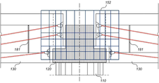
즉, 도 1c에 도시된 바와 같이, 교각기둥(20)의 상부에 형성된 코핑부(11)와 교축방향으로 배치되어 상부의 콘크리트 바닥판을 지지하는 거더(12)가 강결된 연속지점부를 가지는 교량으로서, 상기 연속지점부에서, 상기 코핑부(11)는 상단의 교축방향 양측에 오목한 단차부(11a)가 형성되어 있는 단차형 코핑부로 이루어지며 상기 단차형 코핑부(11a)에는, 교축방향으로 봉 삽입용 관통공이 형성되어 있다.That is, as shown in Fig. 1 (c), the
또한, 상기 코핑부(11)의 교축방향 양측으로 놓이는 거더(12)는 그 단부에 상기 단차형 코핑부의 단차부에 대응되는 절취부(13)가 형성되어 있고, 관통 구멍이 형성된 결합판(14)이 거더의 단부에 교축직각방향으로 일체 구비되어 있다.The
또한, 교축방향으로 단차형 코핑부의 양측으로 단차부(11a)와 절취부(13)가 맞물리도록 거더의 단부가 단차형 코핑부의 단차부에 놓이고, 결합봉(15)이 코핑부(11)의 관통공과 결합판(14)에 형성된 구멍을 관통하여 배치된 후, 결합판(14)의 후방에서 결합봉의 단부에 체결부재가 결합되어 고정되어 단차형 코핑부(11a)와 거더(12)가 일체로 결합되도록 한 것이다.The ends of the girders are placed on the stepped portions of the stepped copings so that the
결국, 연속지점부에서 단차형 코핑부(11a)에 형성시킨 결합봉(15)에 의하여 서로 인접한 거더들을 서로 연결시켜 연속화시키는 것임을 알 수 있다.As a result, it can be seen that the girders adjacent to each other are connected to each other by the joining
하지만 전술한 방법은 특히 거더가 강재 플레이트 거더에 적합 것이므로 사용에 제한적일 수밖에 없고, 연속지점부 연결강성 증진에는 큰 역할을 할 수 없다는 문제점이 있다. 즉, 전술한 방법은 거더가 U형 거더, PSC 빔 거더인 경우에는 적용하기 어렵다는 문제점이 있다.However, the above-described method has a problem that the girder is suitable for the steel plate girder in particular and therefore can not be used in a limited manner and can not play a large role in improving the connection stiffness at the continuous fulcrum. That is, the above-described method has a problem that it is difficult to apply the present invention when the girder is a U-shaped girder or a PSC beam girder.
전술한 문제점을 해결하기 위한 본 발명이 이루고자 하는 기술적 과제는, 교각 연속지점부에서 코핑부, 거더의 단부 및 지점부 콘크리트가 합성된 거더 연결형 코핑부를 형성함으로써, 코핑부의 내하력이 저하되지 않는 범위의 자중을 유지하면서, U형 거더, PSC 빔 거더와 같이 다양한 단면 형태를 가진 거더를 용이하게 연속화시킬 수 있는, 교각 연속지점부를 거더 연결형 코핑부로 형성하는 교량 시공 방법을 제공하기 위한 것이다.According to an aspect of the present invention, there is provided a girder connection type coping portion in which a coping portion, an end portion of a girder, and a fulcrum portion concrete are formed at a continuous pier portion of a pier, The present invention is to provide a bridge construction method in which a girder connection continuous type point portion is formed by a girder connection type coping portion which can easily serialize girders having various cross sectional shapes such as a U-shaped girder and a PSC beam girder while maintaining their own weight.
전술한 기술적 과제를 달성하기 위한 수단으로서, 본 발명에 따른 교각 연속지점부를 거더 연결형 코핑부로 형성하는 교량 시공 방법은, a) 교각을 지반에 시공하고, 내부 돌출철근이 형성된 1차 코핑부를 상기 교각의 상면에 횡방향으로 연장되도록 설치하는 단계; b) 거더들이 교각 연속지점부에 서로 인접되도록 상기 1차 코핑부에 상기 거더들의 단부를 각각 거치시키는 단계; c) 상기 1차 코핑부와 상기 거더들의 단부가 서로 연결될 수 있도록 연결철근을 상기 1차 코핑부의 내부 돌출철근에 조립하는 단계; d) 서로 인접한 상기 거더들이 서로 연속화되도록 상기 1차 코핑부의 상면에 지점부 콘크리트를 타설하여 거더 연결형 코핑부를 형성하는 단계; 및 e) 상기 거더들의 상면 및 상기 지점부 콘크리트의 상면에 콘크리트 슬래브를 형성하는 단계를 포함하되, 상기 b) 단계의 거더는 U형 거더 또는 PSC 빔 거더 이고, 상기 d) 단계에서 상기 1차 코핑부는 상기 지점부 콘크리트에 의해 상기 거더들과 일체화되는 것을 특징으로 한다.According to an aspect of the present invention, there is provided a bridge construction method for constructing a bridge connecting continuous point portion with a girder connecting type coping portion according to the present invention, comprising the steps of: a) constructing a bridge pier on a ground, Extending in the transverse direction on the upper surface of the base plate b) mounting the end portions of the girders to the primary coping portion, respectively, so that the girders are adjacent to each other at the pier end successive portion; c) assembling a connecting reinforcing bar to an inner protruding reinforcing bar of the primary coping portion so that the ends of the primary coping portion and the girders can be connected to each other; d) forming a girder connecting type coping portion by placing a fulcrum concrete on an upper surface of the primary coping portion so that the girders adjacent to each other are continuous with each other; And e) forming a concrete slab on the upper surface of the girders and on the upper surface of the fulcrum concrete, wherein the girder of step b) is a U-girder or PSC beam girder, and in step d) And the portion is integrated with the girders by the fulcrum portion concrete.
여기서, 상기 b) 단계의 거더가 U형 거더인 경우, 상기 1차 코핑부는 양측면에 단차부를 갖는 단차형 코핑부이고 , 상기 단차형 코핑부의 단차부에 각각 상기 U형 거더의 단부가 각각 거치되며, 상기 U형 거더 내부에 내부 긴장재가 설치된 것을 특징으로 한다.If the girder of the step b) is a U-shaped girder, the primary coping portion is a stepped coping portion having stepped portions on both sides, and the end portions of the U-shaped girder are respectively mounted on the stepped portions of the stepped- And an inner tension member is installed inside the U-shaped girder.
여기서, 상기 U형 거더는 칸막이 벽체가 형성되고, 상기 지점부 콘크리트 타설시 상기 칸막이 벽체에 의해 형성된 상기 U형 거더 내부에 채움 콘크리트를 함께 타설하는 것을 특징으로 한다.The U-shaped girder is formed with a partition wall, and the filled concrete is pushed into the U-shaped girder formed by the partition wall when the fiducial concrete is laid.
여기서, 상기 거더가 U형 거더인 경우, 상기 거더 연결형 코핑부는 상기 단차형 코핑부, 상기 U형 거더의 단부, 상기 채움 콘크리트 및 상기 지점부 콘크리트가 합성되어 형성되는 것을 특징으로 한다.When the girder is a U-shaped girder, the girder connecting type coping portion is formed by combining the stepped type coping portion, the end portion of the U-shaped girder, the filled concrete, and the fulcrum portion concrete.
여기서, 상기 단차형 코핑부의 상부에 지점부 긴장재를 삽입 설치하기 위한 지점부 쉬스관을 상기 U형 거더들에 교축방향으로 설치하는 것을 특징으로 한다.Here, a point portion sheath pipe for inserting a fulcrum portion tension member at an upper portion of the stepped portion is installed in the U-shaped girders in the throttling direction.
여기서, 상기 지점부 긴장재 및 상기 내부 긴장재는 각각 강연선이고, 상기 e) 단계 이후에 상기 강연선을 함께 긴장시키는 것을 특징으로 한다.Wherein the fascia tautomeric material and the internal tautomeric material are each a stranded wire, and after the step (e), the stranded wire is tensed together.
여기서, 상기 단차형 코핑부는 인버트 T형(⊥)으로 프리캐스트 제작 또는 현장 타설되고, 상기 단차형 코핑부의 수직방향 높이는 상기 지점부 쉬스관을 설치할 수 있도록 상기 U형 거더의 높이보다 낮게 형성되는 것을 특징으로 한다.In this case, the stepped-type coping portion is pre-casted or in-put into an inverted T-shape (⊥), and the vertical height of the stepped coping portion is lower than the height of the U-shaped girder .
여기서, 상기 b) 단계의 거더가 PSC 빔 거더인 경우, 상기 1차 코핑부는 양측면에 단차부를 갖는 단차형 코핑부이고, 상기 단차형 코핑부의 단차부에 각각 상기 PSC 빔 거더의 단부가 각각 거치되며, 상기 PSC 빔 거더 내부에 내부 긴장재가 설치된 것을 특징으로 한다.If the girder in the step b) is a PSC beam girder, the primary coping unit is a stepped coping unit having stepped portions on both sides thereof, and the end portions of the PSC beam girder are respectively mounted on the stepped portions of the stepped coping unit And an inner tension member is installed inside the PSC beam girder.
여기서, 상기 PSC 빔 거더는 그 상부 플랜지에 상부강판 연결재가 매립되고, 상기 상부강판 연결재는 상부 스플라이스에 의해 볼트 체결되는 것을 특징으로 한다.Here, the PSC beam girder is embedded in the upper flange with the upper steel plate connection member, and the upper steel plate connection member is bolted by the upper splice.
여기서, 상기 단차형 코핑부의 상부에 지점부 긴장재를 삽입 설치되고, 상기 지점부 긴장재 및 상기 내부 긴장재는 각각 강연선이고, 상기 e) 단계 이후에 상기 강연선을 함께 긴장시키는 것을 특징으로 한다.Wherein a fulcrum portion tension member is inserted into the upper portion of the stepped portion, wherein the fulcrum portion tension member and the inner tension member are each a stranded wire, and after the step (e), the stranded wire is tensioned together.
여기서, 상기 단차형 코핑부는 인버트 T형(⊥)으로 프리캐스트 제작 또는 현장 타설되고, 상기 단차형 코핑부의 수직방향 높이는 상기 PSC 빔 거더의 높이와 동일하게 형성되는 것을 특징으로 한다.In this case, the stepped coping portion is pre-cast or in-put into an inverted T-shape (⊥), and the vertical height of the stepped coping portion is formed to be equal to the height of the PSC beam girder.
본 발명에 따르면, 교각 연속지점부에서 코핑부, 거더의 단부 및 지점부 콘크리트가 합성된 거더 연결형 코핑부를 형성함으로써, 코핑부의 내하력이 저하되지 않는 범위의 자중을 유지하면서, U형 거더, PSC 빔 거더와 같이 다양한 단면 형태를 가진 거더를 용이하게 연속화시킬 수 있다.According to the present invention, by forming the girder connecting type coping portion in which the coping portion, the end portion of the girder, and the fulcrum portion concrete are formed at the pier end continuous point portion, the U-shaped girder, the PSC beam The girders having various cross-sectional shapes such as girders can be easily serialized.
본 발명에 따르면, 거더 설치를 위한 교량받침이 필요 없고 연속지점부가 강결되어 신축이음이 필요 없어 사용성이 뛰어난 교량 시공이 가능하게 된다.According to the present invention, there is no need for a bridge support for installing a girder, and a continuous point portion is strong, so that it is possible to construct a bridge having excellent usability without requiring expansion joint.
도 1a 및 도 1b는 종래의 기술에 따른 무코핑 교량의 시공사시도 및 단면도이고, 도 1c는 종래의 기술에 따른 무코핑 교량의 연속지점부 시공사시도이다.
도 2는 본 발명의 실시예에 따른 거더 연결형 코핑부를 구비한 교량에서 거더가 U형 거더인 경우를 나타내는 도면이다.
도 3a 내지 도 3f는 도 2에 도시된 교각 연속지점부를 거더 연결형 코핑부로 형성하는 교량 시공 방법을 나타내는 도면들이다.
도 4는 본 발명의 실시예에 따른 거더 연결형 코핑부를 구비한 교량에서 거더가 PSC 빔 거더인 경우를 나타내는 도면이다.
도 5a 내지 도 5d는 도 4에 도시된 교각 연속지점부를 거더 연결형 코핑부로 형성하는 교량 시공 방법을 나타내는 도면들이다.FIGS. 1A and 1B are construction and cross-sectional views of a muco-ping bridge according to the prior art, and FIG. 1C is an attempt to construct a continuous-pier construction of a muco-ping bridge according to the prior art.
2 is a view showing a case where a girder is a U-shaped girder in a bridge having a girder connecting type coping portion according to an embodiment of the present invention.
FIGS. 3A to 3F are views showing a bridge construction method in which the pierced continuous point portion shown in FIG. 2 is formed as a girder connecting type coping portion.
4 is a view showing a case where a girder is a PSC beam girder in a bridge having a girder connecting type coping unit according to an embodiment of the present invention.
FIGS. 5A to 5D are views showing a bridge construction method in which the pierced continuous point portion shown in FIG. 4 is formed as a girder connecting type coping portion.
아래에서는 첨부한 도면을 참조하여 본 발명이 속하는 기술분야에서 통상의 지식을 가진 자가 용이하게 실시할 수 있도록 본 발명의 실시예를 상세히 설명한다. 그러나 본 발명은 여러 가지 상이한 형태로 구현될 수 있으며 여기에서 설명하는 실시예에 한정되지 않는다. 그리고 도면에서 본 발명을 명확하게 설명하기 위해서 설명과 관계없는 부분은 생략하였으며, 명세서 전체를 통하여 유사한 부분에 대해서는 유사한 도면 부호를 붙였다.Hereinafter, embodiments of the present invention will be described in detail with reference to the accompanying drawings, which will be readily apparent to those skilled in the art. The present invention may, however, be embodied in many different forms and should not be construed as limited to the embodiments set forth herein. In order to clearly illustrate the present invention, parts not related to the description are omitted, and similar parts are denoted by like reference characters throughout the specification.
명세서 전체에서, 어떤 부분이 어떤 구성요소를 "포함"한다고 할 때, 이는 특별히 반대되는 기재가 없는 한 다른 구성요소를 제외하는 것이 아니라 다른 구성요소를 더 포함할 수 있는 것을 의미한다.Throughout the specification, when an element is referred to as "comprising ", it means that it can include other elements as well, without excluding other elements unless specifically stated otherwise.
[교각 연속지점부를 거더 연결형 코핑부로 형성하는 교량 시공 방법][Bridge Construction Method for Consecutive Point of Bridge Piers with Girder Connection Type Coping Section]
본 발명의 실시예에 따른 교각 연속지점부를 거더 연결형 코핑부로 형성하는 교량 시공 방법은, 먼저, 교각을 지반에 시공하고, 내부 돌출철근이 형성된 1차 코핑부를 상기 교각의 상면에 횡방향으로 연장되도록 설치한다. 여기서, 상기 1차 코핑부는 후술하는 바와 같이 단차형 코핑부 또는 평면형 코핑부일 수 있다.A bridge construction method for forming a bridge piercing continuous portion in a girder connection type coping portion according to an embodiment of the present invention is characterized in that a pier bridge is first constructed on a ground and a primary coping portion formed with an inner projecting reinforcing portion is extended to the upper surface of the pier in a lateral direction Install it. Here, the first-order coping portion may be a stepped-type coping portion or a planar-type coping portion as described later.
다음으로, 거더들이 교각 연속지점부에 서로 인접되도록 상기 1차 코핑부에 상기 거더들의 단부를 각각 거치시킨다. 여기서, 상기 거더는 도 2에 도시된 U형 거더, 도 4에 도시된 PSC 빔 거더일 수 있고, 이때, 상기 1차 코핑부는 상기 지점부 콘크리트에 의해 상기 거더들과 일체화된다.Next, the end portions of the girders are respectively mounted on the primary coping portions so that the girders are adjacent to each other at the piercing continuous point portion. Here, the girder may be the U-shaped girder shown in FIG. 2, the PSC beam girder shown in FIG. 4, and the primary coping part is integrated with the girders by the fulcrum part concrete.
다음으로, 상기 1차 코핑부와 상기 거더들의 단부가 서로 연결될 수 있도록 연결철근을 상기 1차 코핑부의 내부 돌출철근에 조립한다.Next, a connecting reinforcing bar is assembled to the inner protruding reinforcing bars of the primary coping portion so that the ends of the primary coping portion and the girders can be connected to each other.
다음으로, 서로 인접한 상기 거더들이 서로 연속화되도록 상기 1차 코핑부의 상면에 지점부 콘크리트를 타설하여 거더 연결형 코핑부를 형성한다.Next, a girder connection type coping portion is formed by placing the fulcrum concrete on the upper surface of the primary coping portion so that the adjacent girders are continuous to each other.
다음으로, 상기 거더들의 상면 및 상기 지점부 콘크리트의 상면에 콘크리트 슬래브를 형성한다.Next, a concrete slab is formed on the upper surface of the girders and the upper surface of the fascia concrete.
이하, 도 2 내지 도 7을 참조하여, 본 발명의 실시예에 따른 교각 연속지점부를 거더 연결형 코핑부로 형성하는 교량 시공 방법에서, 상기 거더는 U형 거더 또는 PSC 빔 거더 일 수 있고, 각각의 실시예에 대해 구체적으로 설명하기로 한다.2 to 7, in a bridge construction method in which a pierced continuous point portion is formed by a girder connecting type coping portion according to an embodiment of the present invention, the girder may be a U-shaped girder or a PSC beam girder, An example will be described in detail.
[제1 실시예: 교각 연속지점부에서 U형 거더 연결시 교량 시공 방법][Embodiment 1: Method of constructing a bridge when a U-shaped girder is connected at a continuous pier portion of a pier]
도 2는 본 발명의 실시예에 따른 거더 연결형 코핑부를 구비한 교량에서 거더가 U형 거더인 경우를 나타내는 도면으로서, 도 2의 상부는 본 발명의 실시예에 따른 거더 연결형 코핑부를 구비한 교량(100)의 개략적인 사시도이고, 도 2의 하부에는 본 발명의 실시예에 따른 거더 연결형 코핑부를 구비한 교량을 구체적으로 나타내는 측단면도이다. 도 3a 내지 도 3f는 도 2에 도시된 교각 연속지점부를 거더 연결형 코핑부로 형성하는 교량 시공 방법을 나타내는 도면들이다.FIG. 2 is a view showing a case where a girder is a U-shaped girder in a bridge having a girder connecting type coping portion according to an embodiment of the present invention, and the upper portion of FIG. 2 is a bridge having a girder connecting type coping portion according to an embodiment of the
도 2를 참조하면, 본 발명의 실시예에 따른 거더 연결형 코핑부를 구비한 교량(100)은, 교각(110), 단차형 코핑부(120), U형 거더(130), 내부 긴장재(140), 연결철근(152), 지점부 쉬스관(160), 지점부 콘크리트(170), 채움 콘크리트(180) 및 콘크리트 슬래브(190)를 포함한다. 여기서, 상기 U형 거더(130)는 U형 단면으로 양 측벽 및 하부플랜지로 형성되는 빔 부재인데, 양 측벽 내부의 PC 강재에 의하여 길이방향으로 프리스트레스가 도입된 철근콘크리트 거더이다. 이때, 거더 연결형 코핑부(200)는 상기 단차형 코핑부(120), 상기 U형 거더들(130)의 단부, 상기 채움 콘크리트(180) 및 상기 지점부 콘크리트(170)가 합성되어 형성된다.2, a
구체적으로, 도 3a 내지 도 3f를 참조하면, 본 발명에 따른 교각 연속지점부를 거더 연결형 코핑부로 형성하는 교량 시공 방법은, 먼저, 도 3a에 도시된 바와 같이, 교각(110)을 지반에 시공하고, 단차부를 갖는 단차형 코핑부(120)를 상기 교각(110)의 상면에 횡방향으로 연장되도록 설치한다. 여기서, 상기 단차형 코핑부(120)는 인버트 T형(⊥)으로 프리캐스트 제작 또는 현장 타설되고, 상기 단차형 코핑부(120)의 수직방향 높이는 지점부 쉬스관(160)을 설치할 수 있도록 상기 U형 거더(130)의 높이보다 낮게 형성된다. 이때, 상기 단차형 코핑부(120)는 내부 돌출철근(151)이 매립되어 돌출될 수 있고, 연결철근(152)과 조립된다.3A to 3F, a method of constructing a bridge connecting continuous point portion with a girder connecting type coping portion according to the present invention comprises: first, constructing a
여기서, 상기 거더가 U형 거더(130)인 경우, 상기 1차 코핑부는 양측면에 단차부를 갖는 단차형 코핑부(120)이고 , 상기 단차형 코핑부120)의 단차부에 각각 상기 U형 거더(130)의 단부가 각각 거치되며, 상기 U형 거더(130) 내부에 내부 긴장재(140)가 설치된다. 이때, 상기 U형 거더(130)는 칸막이 벽체(181)가 형성되고, 상기 지점부 콘크리트(170) 타설시 상기 칸막이 벽체(181)에 의해 형성된 상기 U형 거더(130) 내부에 채움 콘크리트(180)를 함께 타설하게 된다.When the girder is the
다음으로, 도 3b에 도시된 바와 같이, U형 거더들(130)이 교각 연속지점부에 서로 인접되도록 상기 단차형 코핑부(120)의 단차부에 상기 U형 거더들(130)의 단부를 각각 거치시킨다. 이때, 상기 U형 거더들(130)은 상기 단차형 코핑부(120)의 단차부에 대응하는 절취부가 형성되도록 프리캐스트 제작될 수 있다.Next, as shown in FIG. 3B, the ends of the
다음으로, 도 3c에 도시된 바와 같이, 상기 단차형 코핑부(120)와 상기 U형 거더들(130)의 단부가 서로 연결될 수 있도록 상기 단차형 코핑부(120)로부터 돌출된 내부 돌출철근(151) 및 연결철근(152)이 각각 조립된다.3C, an inner
다음으로, 도 3d에 도시된 바와 같이, 상기 단차형 코핑부(120)의 상부에서 지점부 긴장재(161)인 강연선을 삽입 설치하기 위한 지점부 쉬스관(160)을 상기 U형 거더들(130)에 교축방향(종방향)으로 설치한다. 이때, 상기 지점부 쉬스관(160)은 장착홀(162)을 통해 설치될 수 있다.Next, as shown in FIG. 3D, a point
다음으로, 도 3e에 도시된 바와 같이, 서로 인접한 상기 U형 거더들(130)이 서로 연속화되도록 상기 U형 거더(130) 내에 채움 콘크리트(180)를 타설하고, 상기 단차형 코핑부(120)에 지점부 콘크리트(170)를 타설하여 거더 연결형 코핑부(200)를 형성한다. 이때, 채움 콘크리트(180)는 칸막이 벽체(181)에 의해 단차형 코핑부(120)의 양 측방에 제한적으로 타설된다. 즉, 상기 U형 거더들(130)의 단부 내측에 칸막이 벽체(181)에 의해 구획된 공간에 채움 콘크리트(180)가 지점부 콘크리트(170) 타설시 함께 타설되며, 이때, 상기 U형 거더들(130)의 내부에 적어도 하나 이상의 내부 긴장재(140)인 강연선이 형성된다.Next, as shown in FIG. 3E, the filled
다음으로, 도 3f에 도시된 바와 같이, 상기 U형 거더들(130)의 상면 및 상기 지점부 콘크리트(170)의 상면에 콘크리트 슬래브(190)를 형성하고, 상기 연속지점부에 기설치된 내부 긴장재(140) 및 지점부 긴장재(161)를 긴장시킨다. 여기서, 상기 내부 긴장재(140)는 강연선(140)으로서, 상기 U형 거더들(130)의 내부에 형성되고, 지점부 긴장재(161)는 교량에 작용하는 휨 모멘트에 저항하기 위한 강연선으로서, 상기 단차형 코핑부(120)에 상기 U형 거더(130)를 거치한 후 설치되는 상기 지점부 쉬스관(160)에 삽입된다. 즉, 상기 지점부 긴장재(161) 및 상기 내부 긴장재(140)는 각각 강연선이고, 상기 강연선을 함께 긴장시키게 된다.3f, a
이에 따라 상기 거더 연결형 코핑부(200)는 상기 단차형 코핑부(120), 상기 U형 거더들(130)의 단부, 상기 채움 콘크리트(180) 및 상기 지점부 콘크리트(170)가 합성되어 형성된다. 이에 따라 상기 거더 연결형 코핑부(200)는 코핑부의 내하력이 저하되지 않는 범위의 자중을 유지함으로써 교량의 휨하중에 저항할 수 있다. 즉, 상기 거더 연결형 코핑부(200)는 교각(110)의 연속지점부에서 상기 단차형 코핑부(120)를 1차 코핑부로 하고, 상기 U형 거더들(130)의 단부, 상기 채움 콘크리트(180) 및 상기 지점부 콘크리트(170)를 2차 코핑부로 하여 합성되어 서로 인접한 상기 U형 거더들(130)을 교축방향으로 서로 연속화시킬 수 있다.Accordingly, the girder connecting
따라서 본 발명의 실시예에 따른 거더 연결형 코핑부를 구비한 교량에서 거더가 U형 거더(130)인 경우, 교각 연속지점부에서 단차형 코핑부(120), U형 거더(130)의 단부, 채움 콘크리트(180) 및 지점부 콘크리트(170)가 합성된 거더 연결형 코핑부(200)를 형성함으로써, 코핑부의 내하력이 저하되지 않는 범위의 자중을 유지하면서, U형 거더(130)를 용이하게 연속화시킬 수 있다. 또한, U형 거더(130) 설치를 위한 교량받침이 필요 없고 연속지점부가 강결되어 신축이음이 필요 없어 사용성이 뛰어난 교량 시공이 가능하게 된다.Therefore, when the girder is the
[제2 실시예: 교각 연속지점부에서 PSC 빔 거더 연결시 교량 시공 방법][Second Embodiment: Method of constructing a bridge when a PSC beam girder is connected at a continuous point portion of a pier]
한편, 도 4는 본 발명의 실시예에 따른 거더 연결형 코핑부를 구비한 교량에서 거더가 PSC 빔 거더인 경우를 나타내는 도면으로서, 도 4의 상부는 본 발명의 실시예에 따른 거더 연결형 코핑부를 구비한 교량의 개략적인 사시도이고, 도 4의 하부에는 본 발명의 실시예에 따른 거더 연결형 코핑부를 구비한 교량을 구체적으로 나타내는 측단면도이다. 도 5a 내지 도 5d는 도 4에 도시된 교각 연속지점부를 거더 연결형 코핑부로 형성하는 교량 시공 방법을 나타내는 도면들이다.4 is a view showing a case where a girder is a PSC beam girder in a bridge having a girder connecting type coping unit according to an embodiment of the present invention. 4 is a side cross-sectional view showing a bridge having a girder connecting type coping portion according to an embodiment of the present invention. FIGS. 5A to 5D are views showing a bridge construction method in which the pierced continuous point portion shown in FIG. 4 is formed as a girder connecting type coping portion.
도 4를 참조하면, 본 발명의 실시예에 따른 거더 연결형 코핑부를 구비한 교량은, 교각(110), 단차형 코핑부(120), PSC 빔 거더(230), 내부 긴장재(140), 연결철근(152), 지점부 콘크리트(170), 상부강판 연결재(210), 상부 스플라이스(220) 및 콘크리트 슬래브(190)를 포함한다. 여기서, 상기 PSC 빔 거더(230)는 I형 단면으로 상부플랜지, 복부 및 하부플랜지로 형성되는 빔 부재로서, 그 내부의 PC 강재에 의하여 길이방향으로 프리스트레스가 도입된 철근콘크리트 거더이다.4, a bridge having a girder connecting type coping unit according to an embodiment of the present invention includes a
구체적으로, 도 5a 내지 도 5d를 참조하면, 본 발명에 따른 교각 연속지점부를 거더 연결형 코핑부로 형성하는 교량 시공 방법은, 먼저, 도 5a에 도시된 바와 같이, 교각(110)을 지반에 시공하고, 내부 돌출철근(151)이 형성된 단차부를 갖는 단차형 코핑부(120)를 상기 교각(110)의 상면에 횡방향으로 연장되도록 설치한다. 여기서, 상기 단차형 코핑부(120)는 인버트 T형(⊥)으로 프리캐스트 제작 또는 현장 타설되고, 상기 단차형 코핑부(120)의 수직방향 높이는 상기 PSC 빔 거더(230)의 높이와 동일하게 형성될 수 있다. 이때, 상기 단차형 코핑부(120)는 내부 돌출철근(151)이 매립 돌출되어, 연결철근(152)과 조립된다.5A to 5D, a bridge construction method of forming a bridge pier successive point portion with a girder connecting type coping portion according to the present invention includes the steps of constructing a
다음으로, 도 5b에 도시된 바와 같이, PSC(Prestressed Concrete) 빔 거더(230)들이 교각 연속지점부에 서로 인접되도록 상기 단차형 코핑부(120)의 단차부에 상기 PSC 빔 거더들(230)의 단부를 각각 거치시킨다.Next, as shown in FIG. 5B, the
다음으로, 도 5c에 도시된 바와 같이, 상기 단차형 코핑부(120)와 상기 PSC 빔 거더들(230)의 단부가 서로 연결될 수 있도록 상기 단차형 코핑부(120)의 상면에 지점부 콘크리트(170)를 형성하기 위한 연결철근(152)을 조립한다. 구체적으로, 도 4에 도시된 바와 같이, 상기 PSC 빔 거더(230)의 단부에는 빔 관통철근이 삽입될 수 있도록 관통홀(231)이 형성되고, 이때, 상기 관통홀(231)은 상기 PSC 빔 거더(230) 제작시 파이프를 묻어서 형성할 수 있다. 또한, 상기 단차형 코핑부(120)의 내부 돌출철근(151)과 함께 연결철근(152)이 조립 연결되며, 이때, 상기 연결철근(152)이 상기 관통홀(231)에 삽입된다.5c, the stepped-
또한, 도 5c에 도시된 바와 같이, 인접하는 상기 PSC 빔 거더들(230)이 연결될 수 있도록 지점부 긴장재(161)를 설치하고, 상기 단차형 코핑부(120)의 상면에 상부 스플라이스(220)를 체결한다. 이때, 상기 PSC 빔 거더들(230)은 상기 단차형 코핑부(120)의 단차부에 대응하는 절취부가 형성되도록 프리캐스트 제작되고, 그 상면에 상부강판 연결재(210) 및 스터드(211)가 매립 설치된다. 즉, 상기 PSC 빔 거더(230)는 그 상부 플랜지에 상부강판 연결재(210)가 매립되고, 상기 상부강판 연결재(210)는 상부 스플라이스(220)에 의해 볼트 체결된다. 예를 들면, 상기 상부 스플라이스(220)는 하부 덧댐판(221), 상부 덧댐판(222), 볼트(223) 및 너트(224)를 포함할 수 있고, 도 4에 도시된 바와 같이, 상기 PSC 빔 거더(230)에 매립 설치된 상부강판 연결재(210)를 연결하게 된다.5C, a fulcrum
다음으로, 도 5d에 도시된 바와 같이, 서로 인접한 상기 PSC 빔 거더들(230)이 서로 연속화되도록 상기 단차형 코핑부(120)에 콘크리트를 타설하여 거더 연결형 코핑부(200)를 형성한다. 즉, 거더 연결형 코핑부(200)는 상기 단차형 코핑부(120), 상기 PSC 빔 거더들(230)의 단부 및 상기 지점부 콘크리트(170)가 합성되어 형성된다.Next, as shown in FIG. 5D, the girder connecting
또한, 도 5d에 도시된 바와 같이, 상기 PSC 빔 거더들(230)의 상면 및 상기 지점부 콘크리트(170)의 상면에 콘크리트 슬래브(190)를 형성하고, 상기 연속지점부에 기설치된 내부 긴장재(140) 및 지점부 긴장재(161)를 긴장시킨다. 즉, 상기 PSC 빔 거더들(230)의 내부에 적어도 하나 이상의 내부 긴장재(140)인 강연선이 형성되고, 또한, 상기 단차형 코핑부(120)의 상부에 지점부 긴장재(161)를 삽입 설치되며, 상기 지점부 긴장재(161) 및 상기 내부 긴장재(140)는 각각 강연선이고, 상기 강연선을 함께 긴장시키게 된다.5D, a
이에 따라 상기 거더 연결형 코핑부(200)는 상기 단차형 코핑부(120), 상기 PSC 빔 거더들(230)의 단부 및 상기 지점부 콘크리트(170)가 합성되어 형성된다. 즉, 상기 거더 연결형 코핑부(200)는 교각 연속지점부에서 상기 단차형 코핑부(120)를 1차 코핑부로 하고, 상기 PSC 빔 거더들(230)의 단부 및 상기 지점부 콘크리트(170)를 2차 코핑부로 하여 합성되어 서로 인접한 상기 PSC 빔 거더들(230)을 서로 연속화시킬 수 있다.Accordingly, the girder connecting
따라서 본 발명의 실시예에 따른 거더 연결형 코핑부를 구비한 교량에서 거더가 PSC 빔 거더(230)인 경우, 교각 연속지점부에서 단차형 코핑부(120), PSC 빔 거더(230)의 단부 및 지점부 콘크리트(170)가 합성된 거더 연결형 코핑부(200)를 형성함으로써, 코핑부의 내하력이 저하되지 않는 범위의 자중을 유지하면서, PSC 빔 거더(230)를 용이하게 연속화시킬 수 있다. 또한, PSC 빔 거더(230) 설치를 위한 교량받침이 필요 없고 연속지점부가 강결되어 신축이음이 필요 없어 사용성이 뛰어난 교량 시공이 가능하게 된다.Therefore, when the girder is a
결국, 본 발명의 실시예에 따른 거더 연결형 코핑부를 구비한 교량 시공 방법에 따르면, 교각 연속지점부에서 코핑부, 거더의 단부 및 지점부 콘크리트가 합성된 거더 연결형 코핑부를 형성함으로써, 코핑부의 내하력이 저하되지 않는 범위의 자중을 유지하면서, U형 거더, PSC 빔 거더와 같이 다양한 단면 형태를 가진 거더를 용이하게 연속화시킬 수 있다.As a result, according to the bridge construction method including the girder connecting type coping portion according to the embodiment of the present invention, the girder connecting type coping portion formed by combining the coping portion, the end portion of the girder, Girders having various cross-sectional shapes such as a U-shaped girder and a PSC beam girder can be easily continued while maintaining a self weight of a range that does not deteriorate.
전술한 본 발명의 설명은 예시를 위한 것이며, 본 발명이 속하는 기술분야의 통상의 지식을 가진 자는 본 발명의 기술적 사상이나 필수적인 특징을 변경하지 않고서 다른 구체적인 형태로 쉽게 변형이 가능하다는 것을 이해할 수 있을 것이다. 그러므로 이상에서 기술한 실시예들은 모든 면에서 예시적인 것이며 한정적이 아닌 것으로 이해해야만 한다. 예를 들어, 단일형으로 설명되어 있는 각 구성 요소는 분산되어 실시될 수도 있으며, 마찬가지로 분산된 것으로 설명되어 있는 구성 요소들도 결합된 형태로 실시될 수 있다.It will be understood by those skilled in the art that the foregoing description of the present invention is for illustrative purposes only and that those of ordinary skill in the art can readily understand that various changes and modifications may be made without departing from the spirit or essential characteristics of the present invention. will be. It is therefore to be understood that the above-described embodiments are illustrative in all aspects and not restrictive. For example, each component described as a single entity may be distributed and implemented, and components described as being distributed may also be implemented in a combined form.
본 발명의 범위는 상기 상세한 설명보다는 후술하는 특허청구범위에 의하여 나타내어지며, 특허청구범위의 의미 및 범위 그리고 그 균등 개념으로부터 도출되는 모든 변경 또는 변형된 형태가 본 발명의 범위에 포함되는 것으로 해석되어야 한다.The scope of the present invention is defined by the appended claims rather than the detailed description and all changes or modifications derived from the meaning and scope of the claims and their equivalents are to be construed as being included within the scope of the present invention do.
100: 거더 연결형 코핑부를 구비한 교량
200: 거더 연결형 코핑부
110: 교각(Pier)
120: 단차형(인버트 T형) 코핑부
120a: 평면형 코핑부
130: U형 거더
230: PSC 빔(Beam) 거더
140: 내부 긴장재(강연선)
151: 내부 돌출철근
152: 연결철근
160: 지점부 쉬스관
161: 지점부 긴장재(강연선)
170: 지점부 콘크리트
180: 채움 콘크리트
181: 칸막이 벽체
190: 콘크리트 슬래브(Concrete Slab)
210: 상부강판 연결재
211: 스터드
220: 상부 스플라이스(Splice Steel Plate)
221: 하부 덧댐판
222: 상부 덧댐판
223: 볼트
224: 너트
240: 앵커(Anchor)
250: 강봉100: Bridge with girder connection type coping
200: girder connecting type coping portion
110: Pier (Pier)
120: Stepped type (Invert T type)
120a: a planar co-
130: U girder
230: PSC Beam girder
140: Internal tensions (stranded wire)
151: inner protruding bar
152: Connecting bars
160: Branch side sheath tube
161: Branch tension material (strand)
170: Concrete part
180: Filled concrete
181: partition wall
190: Concrete Slab
210: Upper plate joint member
211: Stud
220: Splice Steel Plate
221: Lower folding plate
222: Upper folding plate
223: Bolt
224: Nuts
240: Anchor
250: steel bar
Claims (11)
b) 거더들이 교각 연속지점부에 서로 인접되도록 상기 1차 코핑부에 상기 거더들의 단부를 각각 거치시키는 단계;
c) 상기 1차 코핑부와 상기 거더들의 단부가 서로 연결될 수 있도록 연결철근을 상기 1차 코핑부의 내부 돌출철근에 조립하는 단계;
d) 서로 인접한 상기 거더들이 서로 연속화되도록 상기 1차 코핑부의 상면에 지점부 콘크리트를 타설하여 거더 연결형 코핑부를 형성하는 단계; 및
e) 상기 거더들의 상면 및 상기 지점부 콘크리트의 상면에 콘크리트 슬래브를 형성하는 단계
를 포함하되,
상기 b) 단계의 거더는 U형 거더 또는 PSC(Prestressed Concrete) 빔 거더 이고, 상기 d) 단계에서 상기 1차 코핑부는 상기 지점부 콘크리트에 의해 상기 거더들과 일체화되는 것을 특징으로 하는 교각 연속지점부를 거더 연결형 코핑부로 형성하는 교량 시공 방법.a) installing a bridge pier on the ground and installing a primary coping portion having an inner protruding reinforcing bar so as to extend laterally on the upper surface of the bridge pier;
b) mounting the end portions of the girders to the primary coping portion, respectively, so that the girders are adjacent to each other at the pier end successive portion;
c) assembling a connecting reinforcing bar to an inner protruding reinforcing bar of the primary coping portion so that the ends of the primary coping portion and the girders can be connected to each other;
d) forming a girder connecting type coping portion by placing a fulcrum concrete on an upper surface of the primary coping portion so that the girders adjacent to each other are continuous with each other; And
e) forming a concrete slab on the upper surface of the girders and on the upper surface of the fulcrum concrete
, ≪ / RTI &
Wherein the girder in the step b) is a U-shaped girder or a PSC (Prestressed Concrete) beam girder, and in the step d), the primary coping part is integrated with the girders by the fulcrum concrete. A bridge construction method comprising a girder connection type coping portion.
상기 b) 단계의 거더가 U형 거더인 경우, 상기 1차 코핑부는 양측면에 단차부를 갖는 단차형 코핑부이고 , 상기 단차형 코핑부의 단차부에 각각 상기 U형 거더의 단부가 각각 거치되며, 상기 U형 거더 내부에 내부 긴장재가 설치된 것을 특징으로 하는 교각 연속지점부를 거더 연결형 코핑부로 형성하는 교량 시공 방법.The method according to claim 1,
Wherein when the girder in the step b) is a U-shaped girder, the primary coping portion is a stepped coping portion having stepped portions on both sides thereof, the end portions of the U-shaped girder are respectively respectively mounted on the stepped portions of the stepped- Characterized in that an inner tension member is installed inside the U-shaped girder.
상기 U형 거더는 칸막이 벽체가 형성되고, 상기 지점부 콘크리트 타설시 상기 칸막이 벽체에 의해 형성된 상기 U형 거더 내부에 채움 콘크리트를 함께 타설하는 것을 특징으로 하는 교각 연속지점부를 거더 연결형 코핑부로 형성하는 교량 시공 방법.3. The method of claim 2,
Wherein the U-shaped girder is formed with a partition wall, and the filled concrete is pushed into the U-shaped girder formed by the partition wall when the fulcrum concrete is poured. Construction method.
상기 거더가 U형 거더인 경우, 상기 거더 연결형 코핑부는 상기 단차형 코핑부, 상기 U형 거더의 단부, 상기 채움 콘크리트 및 상기 지점부 콘크리트가 합성되어 형성되는 것을 특징으로 하는 교각 연속지점부를 거더 연결형 코핑부로 형성하는 교량 시공 방법.The method of claim 3,
Wherein when the girder is a U-shaped girder, the girder connecting type coping portion is formed by combining the stepped type coping portion, the end portion of the U-shaped girder, the filled concrete, and the fulcrum portion concrete, A method of constructing a bridge with a coping portion.
상기 단차형 코핑부의 상부에 지점부 긴장재를 삽입 설치하기 위한 지점부 쉬스관을 상기 U형 거더들에 교축방향으로 설치하는 것을 특징으로 하는 교각 연속지점부를 거더 연결형 코핑부로 형성하는 교량 시공 방법.3. The method of claim 2,
And a point portion sheath pipe for inserting a fulcrum portion tension member at an upper portion of the stepped-type coping portion is installed on the U-shaped girders in a throttling direction, wherein the piercing continuous point portion is formed as a girder connecting type coping portion.
상기 지점부 긴장재 및 상기 내부 긴장재는 각각 강연선이고, 상기 e) 단계 이후에 상기 강연선을 함께 긴장시키는 것을 특징으로 하는 교각 연속지점부를 거더 연결형 코핑부로 형성하는 교량 시공 방법.6. The method of claim 5,
Wherein said fulcrums and said inner tensions are each stranded, and after step (e), said strand is tensed together. ≪ Desc / Clms Page number 13 >
상기 단차형 코핑부는 인버트 T형(⊥)으로 프리캐스트 제작 또는 현장 타설되고, 상기 단차형 코핑부의 수직방향 높이는 상기 지점부 쉬스관을 설치할 수 있도록 상기 U형 거더의 높이보다 낮게 형성되는 것을 특징으로 하는 교각 연속지점부를 거더 연결형 코핑부로 형성하는 교량 시공 방법.3. The method of claim 2,
Wherein the stepped coping portion is pre-casted or in-situ with an inverted T-shape (⊥), and a vertical height of the stepped coping portion is formed to be lower than a height of the U-shaped girder so as to install the fulcrum portion sheath tube Wherein the continuous bridge portion is formed of a girder connection type coping portion.
상기 b) 단계의 거더가 PSC 빔 거더인 경우, 상기 1차 코핑부는 양측면에 단차부를 갖는 단차형 코핑부이고, 상기 단차형 코핑부의 단차부에 각각 상기 PSC 빔 거더의 단부가 각각 거치되며, 상기 PSC 빔 거더 내부에 내부 긴장재가 설치된 것을 특징으로 하는 교각 연속지점부를 거더 연결형 코핑부로 형성하는 교량 시공 방법.The method according to claim 1,
Wherein when the girder in the step b) is a PSC beam girder, the primary coping portion is a stepped coping portion having stepped portions on both sides thereof, the end portions of the PSC beam girder are respectively respectively mounted on the stepped portions of the stepped coping portion, Characterized in that an inner tensional element is installed inside the PSC beam girder to form a girder connection type coping portion.
상기 PSC 빔 거더는 그 상부 플랜지에 상부강판 연결재가 매립되고, 상기 상부강판 연결재는 상부 스플라이스에 의해 볼트 체결되는 것을 특징으로 하는 교각 연속지점부를 거더 연결형 코핑부로 형성하는 교량 시공 방법.9. The method of claim 8,
Wherein the PSC beam girder is bolted to the upper flange by an upper splice and the upper steel plate connection member is bolted to the upper flange by the upper splice.
상기 단차형 코핑부의 상부에 지점부 긴장재를 삽입 설치되고, 상기 지점부 긴장재 및 상기 내부 긴장재는 각각 강연선이고, 상기 e) 단계 이후에 상기 강연선을 함께 긴장시키는 것을 특징으로 하는 교각 연속지점부를 거더 연결형 코핑부로 형성하는 교량 시공 방법.9. The method of claim 8,
Characterized in that the fulcrum continuous tension portion is installed on the upper part of the stepped type coping portion and the fulcrum tensions and the inner tension are each a stranded wire and after the step e) A method of constructing a bridge with a coping portion.
상기 단차형 코핑부는 인버트 T형(⊥)으로 프리캐스트 제작 또는 현장 타설되고, 상기 단차형 코핑부의 수직방향 높이는 상기 PSC 빔 거더의 높이와 동일하게 형성되는 것을 특징으로 하는 교각 연속지점부를 거더 연결형 코핑부로 형성하는 교량 시공 방법.9. The method of claim 8,
Wherein the stepped coping portion is pre-casted or in-situ in an inverted T-shape (⊥), and a vertical height of the stepped coping portion is formed to be equal to a height of the PSC beam girder. A method of constructing bridges.
Priority Applications (1)
| Application Number | Priority Date | Filing Date | Title |
|---|---|---|---|
| KR1020140123025A KR20140125754A (en) | 2014-09-16 | 2014-09-16 | Bridge construction method for forming continuous point part of pier using copping for connecting girder |
Applications Claiming Priority (1)
| Application Number | Priority Date | Filing Date | Title |
|---|---|---|---|
| KR1020140123025A KR20140125754A (en) | 2014-09-16 | 2014-09-16 | Bridge construction method for forming continuous point part of pier using copping for connecting girder |
Related Parent Applications (1)
| Application Number | Title | Priority Date | Filing Date |
|---|---|---|---|
| KR1020130025661A Division KR101582599B1 (en) | 2013-03-11 | 2013-03-11 | Bridge construction method for forming continuous point part of pier using copping for connecting girder |
Publications (1)
| Publication Number | Publication Date |
|---|---|
| KR20140125754A true KR20140125754A (en) | 2014-10-29 |
Family
ID=51995410
Family Applications (1)
| Application Number | Title | Priority Date | Filing Date |
|---|---|---|---|
| KR1020140123025A KR20140125754A (en) | 2014-09-16 | 2014-09-16 | Bridge construction method for forming continuous point part of pier using copping for connecting girder |
Country Status (1)
| Country | Link |
|---|---|
| KR (1) | KR20140125754A (en) |
Cited By (4)
| Publication number | Priority date | Publication date | Assignee | Title |
|---|---|---|---|---|
| CN104894954A (en) * | 2015-04-10 | 2015-09-09 | 成军 | Overall mounting and constructing method of pier stud reinforcing steel bars of urban bridge |
| CN110042739A (en) * | 2019-03-14 | 2019-07-23 | 河海大学 | A kind of U-shaped flitch beam of monoblock type clod wash steel plate |
| KR102149716B1 (en) * | 2019-12-13 | 2020-08-31 | 한국콘크리트산업 주식회사 | Pier bridge structure using pc girder and its construction method |
| KR20200134191A (en) * | 2018-10-18 | 2020-12-01 | 주식회사 지랜드피씨 | Precast structure for expanding road |
-
2014
- 2014-09-16 KR KR1020140123025A patent/KR20140125754A/en not_active Application Discontinuation
Cited By (5)
| Publication number | Priority date | Publication date | Assignee | Title |
|---|---|---|---|---|
| CN104894954A (en) * | 2015-04-10 | 2015-09-09 | 成军 | Overall mounting and constructing method of pier stud reinforcing steel bars of urban bridge |
| KR20200134191A (en) * | 2018-10-18 | 2020-12-01 | 주식회사 지랜드피씨 | Precast structure for expanding road |
| CN110042739A (en) * | 2019-03-14 | 2019-07-23 | 河海大学 | A kind of U-shaped flitch beam of monoblock type clod wash steel plate |
| CN110042739B (en) * | 2019-03-14 | 2022-02-01 | 河海大学 | Integral cold-formed steel plate U type composite plate beam |
| KR102149716B1 (en) * | 2019-12-13 | 2020-08-31 | 한국콘크리트산업 주식회사 | Pier bridge structure using pc girder and its construction method |
Similar Documents
| Publication | Publication Date | Title |
|---|---|---|
| KR100423757B1 (en) | Prestressed composite truss girder and construction method of the same | |
| KR100667921B1 (en) | Construction method of pylon using precast concrete beam | |
| KR101178876B1 (en) | Prestressed composit rahmen bridge construdtion method | |
| KR100986207B1 (en) | Precast psc t-type girder bridge and its construction method | |
| JP2007077630A (en) | Continuous girder using precast main-girder segment, and its erection method | |
| KR100993777B1 (en) | Rahmen structure construction method using precast segment | |
| KR20090037419A (en) | Method for constructing precast coping by using multi-step tensioning | |
| KR101582599B1 (en) | Bridge construction method for forming continuous point part of pier using copping for connecting girder | |
| JP3844743B2 (en) | Box girder bridge structure and its construction method | |
| KR20120140386A (en) | Composite girder using inner molding member and bridge construction method therwith | |
| KR100823448B1 (en) | The improved seismic resistant continuation structure of prestressed concrete composite beam bridge and method thereof | |
| KR20140125754A (en) | Bridge construction method for forming continuous point part of pier using copping for connecting girder | |
| KR100911148B1 (en) | Lightened Coping for bridge | |
| KR20120053869A (en) | Bridge construction method using precast end-block with girder connection member | |
| KR20140144035A (en) | The hybrid girder structures prestressed by using the external prestressing mechanism, and the construction method by rigid connection | |
| KR20110041145A (en) | Method for constructing continuous filled steel tube girder bridge | |
| KR101705002B1 (en) | Prefabricated double composite plate girder bridge and its construction method | |
| KR100909004B1 (en) | Hybrid composite girder continuous bridge and constructing method therefor | |
| KR101286112B1 (en) | Composite girder with steel pipe and rahmen bridge construction method using the same | |
| KR101232329B1 (en) | Integral bridge and construction method using arched and concrete-filled tube | |
| KR102033052B1 (en) | Method for constructing truss bridge support with infilled tube using src girder | |
| KR101126042B1 (en) | Steel composite girder prestressed by tendon and method of constructing same | |
| KR100583671B1 (en) | Prestressed concrete beam manufactured by installing steel anchorage devices to various positions and reinforcing member to the upper and lower flanges, and construction method of bridge using the concrete beam | |
| JP3877995B2 (en) | How to build a string string bridge | |
| KR20080111973A (en) | Prestressed steel composite beam and a manufacturing method thereof |
Legal Events
| Date | Code | Title | Description |
|---|---|---|---|
| A107 | Divisional application of patent | ||
| WITN | Withdrawal due to no request for examination |