KR100583671B1 - Prestressed concrete beam manufactured by installing steel anchorage devices to various positions and reinforcing member to the upper and lower flanges, and construction method of bridge using the concrete beam - Google Patents
Prestressed concrete beam manufactured by installing steel anchorage devices to various positions and reinforcing member to the upper and lower flanges, and construction method of bridge using the concrete beam Download PDFInfo
- Publication number
- KR100583671B1 KR100583671B1 KR1020040079403A KR20040079403A KR100583671B1 KR 100583671 B1 KR100583671 B1 KR 100583671B1 KR 1020040079403 A KR1020040079403 A KR 1020040079403A KR 20040079403 A KR20040079403 A KR 20040079403A KR 100583671 B1 KR100583671 B1 KR 100583671B1
- Authority
- KR
- South Korea
- Prior art keywords
- installing
- steel
- bridge
- prestressed concrete
- maintenance
- Prior art date
Links
Images


Classifications
-
- E—FIXED CONSTRUCTIONS
- E01—CONSTRUCTION OF ROADS, RAILWAYS, OR BRIDGES
- E01D—CONSTRUCTION OF BRIDGES, ELEVATED ROADWAYS OR VIADUCTS; ASSEMBLY OF BRIDGES
- E01D21/00—Methods or apparatus specially adapted for erecting or assembling bridges
-
- E—FIXED CONSTRUCTIONS
- E01—CONSTRUCTION OF ROADS, RAILWAYS, OR BRIDGES
- E01D—CONSTRUCTION OF BRIDGES, ELEVATED ROADWAYS OR VIADUCTS; ASSEMBLY OF BRIDGES
- E01D2/00—Bridges characterised by the cross-section of their bearing spanning structure
-
- E—FIXED CONSTRUCTIONS
- E01—CONSTRUCTION OF ROADS, RAILWAYS, OR BRIDGES
- E01D—CONSTRUCTION OF BRIDGES, ELEVATED ROADWAYS OR VIADUCTS; ASSEMBLY OF BRIDGES
- E01D2101/00—Material constitution of bridges
- E01D2101/20—Concrete, stone or stone-like material
- E01D2101/24—Concrete
- E01D2101/26—Concrete reinforced
- E01D2101/28—Concrete reinforced prestressed
- E01D2101/285—Composite prestressed concrete-metal
Landscapes
- Engineering & Computer Science (AREA)
- Architecture (AREA)
- Civil Engineering (AREA)
- Structural Engineering (AREA)
- Bridges Or Land Bridges (AREA)
Abstract
본 발명은 빔의 단부와 측면 및 상부플랜지 등의 다양한 위치에 긴장력을 도입할 수 있는 정착구를 다수개 설치하면서 상부플랜지에 연속화를 위한 강판을 설치하거나 또는 상하부 플랜지에 보강재를 설치하도록 한 프리스트레스트 콘크리트빔을 제작하여 교대 및 교각에 설치하여 교량을 설치하거나, 상기 빔과 빔을 연속화하여 프리스트레스트 콘크리트빔 연속교를 설치하는 교량시공방법에 관한 것이다.The present invention provides a prestressed concrete to install a steel plate for continuity on the upper flange or to install a reinforcement on the upper flange while installing a plurality of anchorages for introducing tension in various positions such as the end and side and the upper flange of the beam The present invention relates to a bridge construction method of manufacturing a beam and installing the bridge by installing the bridge and the bridge, or by installing the prestressed concrete beam continuous bridge by continually constructing the beam and the beam.
상기 프리스트레스트 콘크리트빔은 단위빔의 양측단부에 주인장정착구를 다수개 설치하고, 상기 빔의 상부 일측단부에 연속화를 위한 강판을 설치하고, 상기 빔의 일측 단부에서 상기 단위빔의 길이에 1/3 되는 빔의 상부플랜지 하측에 연속화 및 유지관리용 측면돌출정착구를 설치하고, 상기 단위빔의 양측단부 내측의 하부플랜지 상부에 2차인장 및 유지관리용 측면돌출정착구를 설치하도록 한 단위빔이거나, 또는 단위빔의 양측단부의 상부플랜지 상부에 홈을 형성하여 주인장정착구를 다수개 설치하고, 상기 빔의 상하부 플랜지내에 보강재를 설치하고, 상기 빔의 일측 단부에서 상기 단위빔의 길이에 1/3 되는 빔의 상부플랜지 하측에 연속화 및 유지관리용 측면돌출정착구를 설치하고, 상기 단위빔의 양측단부 내측의 하부플랜지 상부에 2차 인장 및 유지관리용 측면돌출정착구를 설치하여 제작한 것이거나 또는, 상기 프리스트레스트 콘크리트 빔에서 연속화를 위한 연속화 및 유지관리용 측면돌출정착구를 제외하여 제작한 것이다. The prestressed concrete beam is provided with a plurality of host fittings at both ends of the unit beam, a steel plate for continuity is installed at one upper end of the beam, 1/3 of the length of the unit beam at one end of the beam A unit beam configured to install side projection fittings for sequencing and maintenance under the upper flange of the beam to be installed, and to install secondary side tension fixing and maintenance side projections on the upper side of the lower flange inside the two side ends of the unit beam; or A groove is formed in the upper flange of the upper end of both side ends of the unit beam to install a plurality of host mounting fixtures, a reinforcement is installed in the upper and lower flanges of the beam, 1/3 of the length of the unit beam at one end of the beam Side projection fittings for continuation and maintenance are installed under the upper flange of the secondary flange, and the secondary tension is on the upper side of the lower flange inside the both ends of the unit beam. It is produced by installing a maintenance side projecting anchorage for, or, to the production, except for the sequencing for the sequencing in the prestressed concrete beams and maintain the side projecting anchorage for.
상기 제작된 프리스트레스트 콘크리트빔을 교대와 교각에 설치하여 단순교량을 설치하거나, 상기 빔과 빔을 상호 연결하여 프리스트레스트 콘크리트빔 연속교를 설치하는 교량인 것이다. The bridge is to install the prestressed concrete beam to the bridge and piers to install a simple bridge, or to connect the beam and the beam to install a prestressed concrete beam continuous bridge.
Description
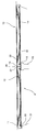
도 1은 본 발명의 프리스트레스트 콘크리트빔을 보여주는 도면. 1 is a view showing a prestressed concrete beam of the present invention.
도 2는 도 1의 단면 A-A를 상세히 보여주는 도면.FIG. 2 shows a detail of section A-A of FIG. 1; FIG.
도 3은 도 1의 단면 B-B를 상세히 보여주는 도면.3 shows a detail of section B-B of FIG. 1;
도 4는 본 발명의 또 다른 실시예인 프리스트레스트 콘크리트빔을 보여주는 도면.4 is a view showing a prestressed concrete beam according to another embodiment of the present invention.
도 5는 도 4의 단면 C-C를 상세히 보여주는 도면.FIG. 5 shows a detail of section C-C of FIG. 4; FIG.
도 6은 도 4의 단면 D-D를 상세히 보여주는 도면.6 shows a detail of the section D-D of FIG. 4;
도 7은 도 4의 단면 E-E를 상세히 보여주는 도면.FIG. 7 shows a detail of section E-E of FIG. 4; FIG.
도 8은 본 발명의 프리스트레스트 콘크리트빔을 연속화하여 교량을 설치한 것을 보여주는 도면.8 is a view showing that the bridge is installed by continuing the prestressed concrete beam of the present invention.
도 9는 본 발명의 또 다른 실시예인 프리스트레스트 콘크리트빔을 연속화하 여 교량을 설치한 것을 보여주는 도면.9 is a view showing that the bridge is installed by continuing the prestressed concrete beam is another embodiment of the present invention.
도 10은 본 발명의 프리스트레스트 콘크리트빔을 연속화하기 위한 연속화연결부를 보여주는 도면.10 is a view showing a continuum connection for continuizing the prestressed concrete beam of the present invention.
도 11은 도 10의 연속화연결부의 단면을 보여주는 도면.11 is a view showing a cross-section of the continuous connection of FIG.
도 12는 본 발명의 프리스트레스트 콘크리트빔의 상하부 플랜지에 설치한 보강재의 또 다른 설치예를 보여주는 도면. 12 is a view showing another installation example of the reinforcing material installed on the upper and lower flanges of the prestressed concrete beam of the present invention.
도 13은 도 12의 보강재의 설치방법을 정면에서 보여주는 도면.13 is a view showing the installation method of the reinforcement of Figure 12 from the front.
도 14는 본 발명의 보강재의 또다른 실시예를 보여주는 도면.14 shows another embodiment of the reinforcement of the present invention.
도 15는 본 발명의 또 다른 실시예인 프리스트레스트 콘크리트빔을 연속화하여 교량을 설치한 것을 보여주는 도면.15 is a view showing that the bridge is installed by continuing the prestressed concrete beam is another embodiment of the present invention.
도 16은 도 15의 F부분을 상세히 보여주는 도면.FIG. 16 is a detailed view of portion F of FIG. 15;
도 17은 도 15의 G부분을 상세히 보여주는 도면.FIG. 17 is a view showing portion G of FIG. 15 in detail;
-도면의 주요 부분에 대한 부호의 설명-Explanation of symbols on main parts of drawing
A : 프리스트레스트 콘크리트빔 연속교A: Prestressed Concrete Beam Continuous Bridge
10 : 프리스트레스트 콘크리트빔10: prestressed concrete beam
11 : 주인장정착구11: owner's stop
12 : 연속화 및 유지관리용 측면돌출정착구 12: Side protrusion stop for continuity and maintenance
13 : 강판 14 : PC강재13
15 : 2차인장 및 유지관리용 측면돌출정착구15: Side protrusion stop for 2nd tensile and maintenance
16 : 상부플랜지 17 : 하부플랜지16: upper flange 17: lower flange
19 : 볼트너트연결 20 : 연속화연결부19: Bolt nut connection 20: Continuous connection
21 : 교대 22 : 교좌장치21: shift 22: the instrument
23 : 교각 24 : 연속화강봉삽입파이프23: pier 24: continuous steel rod insertion pipe
25 : 연속화강봉 26 : 에폭시충전25: continuous steel bar 26: epoxy filling
27 : 콘크리트충전 30 : 보강재27: concrete filling 30: reinforcing material
31 : 고정볼트 32 : 보강강판31: fixing bolt 32: reinforcing steel sheet
33 : 강봉 또는 철근 또는 복합섬유봉 34 : 강봉고정고리33: steel bar or reinforcing bar or composite fiber bar 34: steel bar fixing ring
41 : 주인장 정착블럭 35 : 파형강판41: host settlement block 35: corrugated steel sheet
42 : 주인장 및 연속화인장 겸용 정착블럭42: Settlement block for both owner and continuous painting
본 발명은 빔의 단부와 측면 및 상부플랜지 등의 다양한 위치에 긴장력을 도입할 수 있는 정착구를 다수개 설치하면서 상부플랜지에 연속화를 위한 강판을 설치하거나 또는 상하부 플랜지에 보강재를 설치하도록 한 프리스트레스트 콘크리트빔을 제작하여 교대 및 교각에 설치하여, 단순 교량을 설치하거나, 상기 빔과 빔을 연속화하여 프리스트레스트 콘크리트빔 연속교를 설치하는 교량설치방법에 관한 것이다. The present invention provides a prestressed concrete to install a steel plate for continuity on the upper flange or to install a reinforcement on the upper flange while installing a plurality of anchorages for introducing tension in various positions such as the end and side and the upper flange of the beam The present invention relates to a bridge installation method for manufacturing a beam and installing the bridge and a pier, or installing a simple bridge, or installing the prestressed concrete beam continuous bridge by sequencing the beam and the beam.
상기 프리스트레스트 콘크리트빔은 단위빔의 양측단부에 주인장정착구를 다수개 설치하고, 상기 빔의 상부 일측단부에 연속화를 위한 강판을 설치하고, 상기 빔의 일측 단부에서 상기 단위빔의 길이에 1/3 되는 빔의 상부플랜지 하측에 연속화 및 유지관리용 측면돌출정착구를 설치하고, 상기 단위빔의 양측단부 내측의 하부플랜지상부에 2차 인장 및 유지관리용 측면돌출정착구를 설치하도록 한 단위빔이거나, The prestressed concrete beam is provided with a plurality of host fittings at both ends of the unit beam, a steel plate for continuity is installed at one upper end of the beam, 1/3 of the length of the unit beam at one end of the beam It is a unit beam to install the side projection anchorage for continuity and maintenance under the upper flange of the beam to be installed, and to install the side projection anchorage for secondary tension and maintenance on the lower flange inside the both ends of the unit beam,
또는 단위빔의 양측단부의 상부플랜지 상부에 홈을 형성하여 주인장정착구를 다수개 설치하고, 상기 빔의 상하부 플랜지내에 보강재를 설치하고, 상기 빔의 일측 단부에서 상기 단위빔의 길이에 1/3 되는 빔의 상부플랜지 하측에 연속화 및 유지관리용 측면돌출정착구를 설치하고, 상기 단위빔의 양측단부 내측의 하부플랜지 상부에 2차 인장 및 유지관리용 측면돌출정착구를 설치하여 제작한 것이거나, 또는 상기 프리스트레스트 콘크리트 빔에서 연속화를 위한 연속화 및 유지 관리용 측면 돌출정착구를 제외하여 제작한 것이다. Alternatively, grooves are formed in upper portions of upper flanges of both side ends of the unit beam, and a plurality of host fittings are provided, and reinforcement is installed in upper and lower flanges of the beam, and 1/3 of the length of the unit beam is formed at one end of the beam. It is manufactured by installing side projection fittings for continuity and maintenance under the upper flange of the beam, and installing side projection fittings for secondary tension and maintenance on the upper side of the lower flange inside the two side ends of the unit beam, or the It is manufactured by excluding lateral protrusions for continuity and maintenance for continuity in prestressed concrete beams.
상기 제작된 프리스트레스트 콘크리트빔을 교대와 교각에 설치하여 교량을 설치하거나, 상기 빔과 빔의 상부플랜지내에 설치된 연속화 강봉 또는 강판을 볼트와 너트로 연결을 한 다음, 콘크리트로 충전을 한 연속화연결부를 형성하고, 상기 빔과 빔의 단부면이 서로 접하는 면은 에폭시로 충전하도록 한 다음, 상기 연속화 및 유지관리용 측면돌출정착구에 연결된 PC강재에 긴장력을 도입하여 정착한 후에, 교량 슬래브를 타설한 다음 2차 인장 및 유지관리용 측면돌출정착구에 연결된 PC강재에 긴장력을 도입하여 연속화된 프리스트레스트 콘크리트빔 연속교를 설치하는 것이다.The bridge is installed by installing the prepared prestressed concrete beams on the bridges and piers, or connecting the continuous steel rods or steel plates installed in the beam and the upper flange of the beams with bolts and nuts, and then connecting the continuous connections filled with concrete. After forming, the beam and the end surface of the beam contact each other to be filled with epoxy, and after the tension is introduced and fixed to the PC steel connected to the continuation and maintenance side projection fitting, the bridge slab is poured It is to install continuous prestressed concrete beam continuous bridge by introducing tension force to PC steel connected to side protruding anchor for secondary tension and maintenance.
본 발명의 목적은 상기 프리스트레스트 콘크리트빔의 다양한 위치에 다양한 목적을 위하여 설치한 정착구에 PC강재를 연결하여 긴장력을 도입하고, 상부플랜지내에 설치된 연속화 강판을 이용하여 연속화를 하거나 또는 상하부 플랜지내에 보강재를 설치하여 빔의 내하력을 증강시키도록 한 후에, 빔과 빔을 상호 연결하여 연속화를 하면서 연속화를 위한 정착구에 PC 강재를 설치하여 긴장력을 도입하여 연속화된 교량의 연속화부분을 강화하고, 추후에 유지보수를 위한 강재 정착구를 이용하여 유지보수를 하는 것으로서 빔의 상하부 플랜지에 설치된 보강재는 빔에서 발생되는 균열을 방지함과 동시에 상기 빔의 다양한 위치에 설치된 PC강재에 보다 많은 양의 긴장력을 도입하여 상기 빔에 소요되는 철근양을 감소시킬 수 있으며, 또한 상기 빔의 형고를 적게 하여 충분한 형하공간을 확보하면서 빔의 지지력을 향상시켜 빔을 장지간할 수 있는 프리스트레스트 콘크리트빔 연속교의 설치방법을 제공하는데 있다. An object of the present invention is to introduce a tension force by connecting the PC steel to the anchorage installed for various purposes at the various positions of the prestressed concrete beam, and by using a continuous steel plate installed in the upper flange or continuous reinforcement in the upper and lower flanges After the installation to increase the load capacity of the beam, by connecting the beam and the beam to the continuity while installing PC steel in the anchorage for continuity to introduce the tension force to strengthen the continuity of the continuous bridge, and later maintenance Maintenance by using the steel anchorage for the reinforcement is installed on the upper and lower flanges of the beam to prevent cracks generated in the beam and at the same time to introduce a greater amount of tension to the PC steel installed in various positions of the beam Can reduce the amount of rebar required, and also the shape of the beam The present invention provides a method of installing a prestressed concrete beam continuous bridge that can secure long enough space by reducing the height and improve the bearing capacity of the beam.
또한, 상기 연속화를 위한 정착구를 제외하고 제작한 프리스트레스트 콘크리트 빔을 교대 및 교각에 설치한 단순교의 설치방법도 동시에 제공하고자 한다.In addition, to provide at the same time the installation method of a simple bridge is installed on the alternating and piers precast concrete beams, except for the anchorage for the continuity.
일반적으로 철근 콘크리트에 강연선을 설치하여 긴장력을 도입한 PC철근 콘크리트빔은 강연선에 긴장력을 도입하면 상부에 인장력에 의한 균열로 인하여 강연선에 도입할 수 있는 긴장력에 한계가 있어 빔의 지간이 작아지면서 형고인 빔의 높이가 커지는 문제점이 있다.In general, PC reinforced concrete beams in which reinforced wires are introduced into reinforced concrete have tension, and when the tension is introduced into the reinforced steel, there is a limit to the tension force that can be introduced into the stranded wire due to cracking caused by the tensile force on the upper side. There is a problem that the height of the deceased beam is increased.
또한, 시간이 지남에 따라 빔에 작용하는 정모멘트에 의하여 발생되는 인장 력을 견디지 못하여 빔의 하부에 균열이 발생되어 교량으로서의 역할을 하지 못하는 문제점이 있다.In addition, there is a problem that can not withstand the tensile force generated by the positive moment acting on the beam over time, so that a crack is generated in the lower portion of the beam does not serve as a bridge.
또한 균열에 의한 철근이 부식되며 대기의 오염으로 인하여 콘크리트와 철근의 부착력이 떨어져 빔의 강도에 심각한 영향을 주므로 교량의 내구연한을 감소시키는 문제점이 있다.In addition, there is a problem in reducing the durability of the bridge because the reinforcing bars due to cracks and corrosion of the air has a serious impact on the strength of the beam because the adhesion between the concrete and the reinforcing bar is reduced.
또한, 갑작스런 교량의 붕괴를 우려하여 교량의 유지보수관리를 지속적으로 해야하는 문제점이 있다.In addition, there is a problem that the maintenance management of the bridge must be continued in fear of the sudden collapse of the bridge.
이에, 본 발명은 이상과 같은 사항을 감안하여 제안된 것으로서, 상기 프리스트레스트 콘크리트빔의 다양한 위치에 PC강재를 설치할 수 있는 정착구를 설치하고, 상부플랜지내에 연속화 강판을 설치하거나 또는 상하부 플랜지내에 보강재를 설치하여 빔의 지내력을 강화시켜 빔에 발생되는 균열을 방지할 수 있으며, 상기 정착구를 이용하여 보다 많은 양의 긴장력을 도입할 수 있어 상기 빔의 지간을 장지간화를 할 수 있으며 또한 빔의 형고를 줄일 수 있어 보다 강한 교량과 형고가 작은 빔을 설치함으로써 외관이 미려한 교량을 설치하는데 있다.
Accordingly, the present invention has been proposed in view of the above matters, and installs a fixing device for installing PC steel at various positions of the prestressed concrete beam, installs a continuous steel sheet in the upper flange, or reinforcement in the upper and lower flanges. It is possible to prevent cracks generated in the beam by strengthening the bearing strength of the beam, and it is possible to introduce a greater amount of tension force by using the anchorage, which makes the interval between the beams longer and longer. It is possible to install a bridge with a beautiful appearance by installing a stronger bridge and a smaller beam.
상기의 목적을 달성하기 위하여, 본 발명은 빔(10)의 단부와 측면 및 상부플랜지(16) 등의 다양한 위치에 긴장력을 도입할 수 있는 정착구(11,12,15)를 다수개 설치하면서 상부플랜지(16)에 연속화를 위한 강판(13)을 설치하거나 또는 상하부 플랜지(16,17)에 보강재(30)를 설치하도록 한 프리스트레스트 콘크리트빔(10)을 제작하여 교대(21) 및 교각(23)에 설치하고, 상기 빔과 빔을 연속화하여 프리스트레스트 콘크리트빔 연속교(A)를 설치하는 방법에 관한 것이다.In order to achieve the above object, the present invention, while installing a plurality of anchors (11, 12, 15) that can introduce a tension force in various positions, such as the end and side and the
상기 프리스트레스트 콘크리트빔(10)은 단위빔의 양측단부에 주인장정착구(11)를 다수개 설치하고, 상기 빔의 상부 일측단부에 연속화를 위한 강판(13)을 설치하고, 상기 빔의 일측 단부에서 상기 단위빔의 길이에 1/3 되는 빔의 상부플랜지(16) 하측에 연속화 및 유지관리용 측면돌출정착구(12)를 설치하고, 상기 단위빔의 양측단부 내측의 하부플랜지(17) 상부에 2차 인장 및 유지관리용 측면돌출정착구(15)를 설치하도록 한 단위빔이거나, The
또는 단위빔의 양측단부의 상부플랜지(16) 상부에 홈을 형성하여 주인장정착구(11)를 다수개 설치하고, 상기 빔의 상하부 플랜지(16,17)내에 보강재(30)를 설치하고, 상기 빔의 일측 단부에서 상기 단위빔의 길이에 1/3 되는 빔의 상부플랜지(16) 하측에 연속화 및 유지관리용 측면돌출정착구(12)를 설치하고, 상기 단위빔의 양측단부 내측의 하부플랜지(17) 상부에 2차 인장 및 유지관리용 측면돌출정착구(15)를 설치하여 제작한 것이다.Alternatively, grooves may be formed in upper portions of the
상기 제작된 프리스트레스트 콘크리트빔(10)을 교대(21)와 교각(23)에 설치하고, 상기 빔과 빔의 상부플랜지(16)내에 설치된 연속화 강봉(25) 또는 강판(13)을 볼트와 너트로 연결(19)을 한 다음 콘크리트로 충전(27)을 한 연속화연결부(20)를 형성하고, 상기 빔과 빔의 단부면이 서로 접하는 면은 에폭시 충전(26)을 한 다 음 상기 연속화 및 유지관리용 측면돌출정착구(12)에 연결된 PC 강재(14)에 긴장력을 도입하여 정착한 후에 교량 슬래브를 타설한 다음 2차 인장 및 유지관리용 측면돌출정착구(15)에 연결된 PC강재(14)에 긴장력을 도입하여 연속화된 프리스트레스트 콘크리트빔 연속교(A)를 설치하는 것에 특징이 있다.The fabricated
이에 따른 빔의 제작방법과 이를 이용한 연속교 설치방법은 다음과 같다.The beam manufacturing method and the continuous bridge installation method using the same are as follows.
a) 프리스트레스트 콘크리트빔(10)을 형성하기 위하여 철근을 조립하는 단계;a) assembling the reinforcing bars to form the
b) 상기 프리스트레스트 콘크리트빔의 양측단부의 중앙부에 주인장정착구(11)를 설치하거나 또는 상기 프리스트레스트 콘크리트빔의 상부플랜지(16) 상부에 주인장정착구(11)를 설치하고, 상기 빔의 양측 하부플랜지(17) 상부에 2차 인장 및 유지관리용 측면돌출정착구(15)를 설치하고, 일측단부의 일정한 위치에 연속화를 위한 연속화 및 유지관리용 측면돌출정착구(12)를 설치하는 단계; b) installing the
c) 상기 빔의 상부플랜지(16) 일측단부에 일정한 길이를 갖는 연속화 강판(13)을 설치하거나 또는 빔의 상하부 플랜지(16,17) 전체길이에 걸쳐 보강재(30)를 설치하는 단계; c) installing a
d) 상기의 단계가 완료된 후에 콘크리트를 타설양생하여 빔(10)을 제작하는 단계; d) after the step is completed to pour the concrete to produce a beam (10);
e) 제작된 빔을 교각 및 교대에 설치하고 중앙 교각에서는 빔과빔을 연결하여 연속화연결부(20)를 설치하고, 상기 연속화연결부에 콘크리트 충전(27)하면서 상기 빔과 빔이 측면에서 서로 접하는 부분은 에폭시충전(26)을 하여 밀착시키는 단계; e) the fabricated beams are installed in the piers and shifts, and in the central piers, the beams and beams are connected to each other to install the
f) 인접하여 설치된 빔의 각각의 일측단부에 설치된 상기 연속화 및 유지관리용 측면돌출정착구(12)에 PC강재(14)를 상호 연결한 다음 긴장력을 도입하여 고정 정착한 후에 교량 슬래브를 타설 양생한 다음 하부플랜지(17) 상부에 설치된 2차 인장 및 유지관리용 측면돌출정착구(15)에 거치된 PC강재(14)를 긴장한 후에 고정 정착하여 프리스트레스트 콘크리트빔 연속교(A)를 설치하는 단계로 이루어진 것에 특징이 있다.f) The PC steels 14 are interconnected to the continuity and maintenance
이하 본 발명의 구성 및 작용을 첨부된 도면에 의하여 상세히 설명하면 다음과 같다.Hereinafter, the configuration and operation of the present invention will be described in detail with reference to the accompanying drawings.
도 1은 본 발명의 프리스트레스트 콘크리트빔을 보여주는 도면으로서, 빔의 단부와 측면 및 상부플랜지등의 다양한 위치에 긴장력을 도입할 수 있는 주인장 정착구(11,12,15)를 다수개 설치하면서 상부플랜지(16)에 연속화를 위한 강판(13)을 설치하거나 또는 상하부 플랜지(16,17)에 보강재(30)를 설치하도록 한 프리스트레스트 콘크리트빔(10)을 제작하여 교대 및 교각에 설치하고, 상기 빔과 빔을 연속화하여 프리스트레스트 콘크리트빔 연속교(A)를 설치하기 위하여 제작하는 빔에 관한 것으로서, 1 is a view showing a prestressed concrete beam of the present invention, the upper flange while installing a plurality of host anchorages (11, 12, 15) that can introduce tension in various positions such as the end and side and the upper flange of the beam A prestressed
상기 프리스트레스트 콘크리트빔(10)은 단위빔의 양측단부의 중앙부에 주인장정착구(11)를 다수개 설치하고, 상기 빔의 상부 일측단부에 연속화를 위한 강판(13)을 설치하고, 상기 빔의 일측 단부에서 상기 단위빔의 길이에 1/3 되는 빔의 상부플랜지(16) 하측에 연속화 및 유지관리용 측면돌출정착구(12)를 설치하고, 상기 단위빔의 양측단부 내측의 하부플랜지(17) 상부에 2차 인장 및 유지관리용 측면돌출정착구(15)를 설치하여 제작한 단위빔(10)이다.The prestressed
상기 연속화 및 유지관리용 측면돌출정착구(12)는 빔과 빔의 일측단부의 상부에 설치된 강판(13)을 볼트와 너트로 연결하여 연속화연결부(20)를 형성하면서 상기 인접하여 설치된 빔의 일측 단부에 마주보고 설치된 각각의 연속화 및 유지관리용 측면돌출정착구(12)에 PC강재(14)를 연결한 다음 긴장력을 도입하고, 정착하여 상기 강판(13)을 연결하면서 상기 정착구(12)에 연결된 PC강재(14)를 이용하여 상호 연결시킨 것이며, 또한 상기 정착구(12)를 이용하여 향후에 상기 교량에 대한 유지보수를 실시할 때 상기 PC 강재(14)를 재긴장하여 상기 빔에 내하력을 보강하기 위하여 측면에 돌출 설치된 것은 상기 2차 인장 및 유지관리용 측면돌출정착구(15)와 같은 목적으로 설치된 것이다. The continuation and maintenance side projection fitting 12 is connected to the
도 2는 도 1의 단면 A-A를 상세히 보여주는 도면으로서, 상기 도 1의 빔의 지점부 즉 빔의 양측단부의 상하부 플랜지(16,17) 및 복부에 설치된 주인장정착구(11)와 연속화 및 유지관리용 측면돌출정착구(12) 및 2차 인장 및 유지관리용 측면돌출정착구(15)를 보여주는 것이며, 상기 빔과 빔을 연속화 하기 위하여 빔의 상부인 상부플랜지(16)내에 강판(13)을 일정 길이로 배치한 것을 보여주는 것이다. FIG. 2 is a cross-sectional view of the cross section AA of FIG. 1, in which the upper and
도 3은 도 1의 단면 B-B를 상세히 보여주는 도면으로서, 상기 도 1의 빔의 중앙부 즉 빔의 중앙부의 상하부 플랜지 및 복부에 설치된 주인장정착구(11)에 연결된 주인장PC강재(14)와 연속화 및 유지관리용 측면돌출정착구(12) 및 2차 인장 및 유지관리용 측면돌출정착구(15)에 연결된 PC강재(14)를 보여주는 것이다.FIG. 3 is a cross-sectional view of the cross-sectional view BB of FIG. 1, which is serialized and maintained with a
도 4는 본 발명의 또 다른 실시예인 프리스트레스트 콘크리트빔을 보여주는 도면으로서, 빔의 상부플랜지(16)의 상부, 측면 및 하부플랜지등의 다양한 위치에 긴장력을 도입할 수 있는 정착구를 다수개 설치하면서 상하부 플랜지에 보강재를 설치한 프리스트레스트 콘크리트빔을 제작하여 교대 및 교각에 설치하고, 상기 빔과 빔을 연속화하여 프리스트레스트 콘크리트빔 연속교를 설치하기 위하여 제작하는 빔에 관한 것으로서,4 is a view showing a prestressed concrete beam according to another embodiment of the present invention, while installing a plurality of anchorages capable of introducing tension in various positions such as upper, side, and lower flanges of the
상기 프리스트레스트 콘크리트빔(10)의 양측단부의 상부플랜지(16) 상부에 홈을 형성하여 주인장정착구(11)를 다수개 설치하고, 상기 빔의 상하부 플랜지(16,17)내에 보강재(30)를 설치하고, 상기 빔의 일측 단부에서 상기 단위빔의 길이에 1/3 되는 빔의 상부플랜지(16) 하측에 연속화 및 유지관리용 측면돌출정착구(12)를 설치하고, 상기 단위빔의 양측단부 내측의 하부플랜지(17) 상부에 2차 인장 및 유지관리용 측면돌출정착구(15)를 설치하여 제작한 단위빔(10)이다. Grooves are formed in the
상기 연속화 및 유지관리용 측면돌출정착구(12)는 빔과 빔의 상부플랜지(16)내에 설치된 보강재(30)를 상호 연결하여 연속화연결부(20)를 형성하면서 상기 인접하여 설치된 빔의 일측단부에 마주보고 설치된 각각의 연속화 및 유지관리용 측면돌출정착구(12)에 PC강재(14)를 연결한 다음 긴장력을 도입하고, 정착하여 상기 강판(13)을 연결하면서 상기 정착구에 연결된 PC강재를 이용하여 상호 연결시킨 것이며, 또한 상기 정착구를 이용하여 향후에 상기 교량에 대한 유지보수를 실시할 때 상기 PC 강재를 재긴장하여 상기 빔에 내하력을 보강하기 위하여 측면에 돌출 설치된 것은 상기 2차 인장 및 유지관리용 측면돌출정착구(15)와 같은 목적으로 설치된 것이다.The continuation and maintenance side protrusion fitting 12 is connected to the
또한, 상기 주인장정착구(11)는 상기 빔의 양측단부의 상부플랜지(16)의 상부에 홈을 형성하고, 상기 홈내에 주인장정착구(11)를 다수개 설치하고 PC강재(14)를 연결하여 긴장력을 도입한 것으로서 종전의 방법인 주인장정착구(11)를 빔의 양측단부의 중앙부에 설치한 것과 다르게 설치한 것으로서, 빔의 상부에 설치하므로서 긴장력 도입시 중심축에서 상기 정착구까지의 거리가 종전의 단부 중앙에 설치한 정착구에서 중십축까지의 거리가 길어 긴장력을 도입할 때 종전과 같은 힘을 작용하더라도 팔길이인 중심축에서 정착구까지의 거리가 길어 종전에 도입된 힘보다 크게 도입할 수 있어 효과적으로 프리스트레스를 도입할 수 있다.In addition, the
도 5는 도 4의 단면 C-C를 상세히 보여주는 도면으로서, 상기 도 4의 빔의 지점부 즉 빔의 양측단부의 상하부 플랜지 및 복부에 설치된 주인장정착구(11)와 연속화 및 유지관리용 측면돌출정착구(12) 및 2차 인장 및 유지관리용 측면돌출정착구(15)를 보여주는 것이며, 상기 빔을 구조적으로 보강하기 위한 보강재(30)를 상하부 플랜지(16,17)내에 설치함과 동시에 상기 빔과 빔을 연속화하기 위하여 상기 빔의 일측단에 돌출 설치된 상기 보강재(30)에 볼트와 너트로 연결(19)을 한 것이다.5 is a detailed cross-sectional view of the cross-sectional view CC of Figure 4, the upper and lower flanges and the upper and lower flanges of the point portion of the beam of Figure 4, both sides of the beam and the
도 6은 도 4의 단면 D-D를 상세히 보여주는 도면으로서, 상기 도 4의 빔의 양측단부에서 일정길이 떨어져 설치된 연속화 및 유지관리용 측면돌출정착구(12)가 설치된 부분을 보여주는 것으로서, 빔의 상하부 플랜지(16,17)내에 보강재(30)를 설치하고, 상부플랜지(16)의 하부에 일정한 거리인 빔의 전체길이의 1/3되는 위치에 설치된 연속화 및 유지관리용 측면돌출정착구(12)와 하부플랜지(17) 상부에 설치된 2차인장 및 유지관리용 측면돌출정착구(15)에 연결된 PC강재(14)를 보여주는 것이며, 상기 빔의 복부에 주인장정착구(11)에 연결된 PC강재(14)가 설치된 것을 보여주는 것이다.FIG. 6 is a detailed view of the cross-sectional view DD of FIG. 4, which shows a portion in which the
도 7은 도 4의 단면 E-E를 상세히 보여주는 도면으로서, 상기 도 4의 빔의 중앙부 즉 빔의 중앙부의 상하부 플랜지 및 복부에 각각 설치된 주인장정착구(11)에 연결된 주인장PC강재(14)와 2차인장 및 유지관리용 측면돌출정착구(15)에 연결된 PC강재(14)와 빔의 상하부 플랜지(16,17)내에 설치된 보강재(30)를 보여주는 것이다. FIG. 7 is a detailed view of the cross-section EE of FIG. 4, in which the
도 8은 본 발명의 프리스트레스트 콘크리트빔을 연속화하여 교량을 설치한 것을 보여주는 도면으로서, 프리스트레스트 콘크리트빔(10)을 형성하기 위하여 철근을 조립하고, 상기 조립된 철근 빔의 양측단부의 중앙부에 주인장정착구(11)를 설치하면서 PC 강재(14)를 연결하고, 상기 빔의 양측 하부플랜지(17) 상부에 2차 인장 및 유지관리용 측면돌출정착구(15)를 설치하고, 일측단부의 일정한 위치에 연속화를 위한 연속화 및 유지관리용 측면돌출정착구(12)를 설치한 후에 상기 빔의 상부플랜지(16) 일측단부에 일정한 길이를 갖는 연속화 강판(13)을 설치한 후에 콘크리트를 타설 양생하여 프리스트레스트 콘크리트빔(10)을 제작하고, 상기 제작된 빔(10)을 교각 및 교대에 설치하고 중앙 교각에서는 빔과 빔을 연결하기 위하여 상부플랜지(16)내에 설치된 강판(13)을 볼트와 너트로 연결(19)을 한 연속화연결부 (20)를 설치하고, 상기 연속화연결부(20)에 콘크리트충전(27)을 하면서 상기 빔과 빔이 측면에서 서로 접하는 부분은 에폭시충전(26)을 하여 밀착시킨 후에 교각에 인접하여 설치된 빔의 각각의 일측단부에 설치된 상기 연속화 및 유지관리용 측면돌출정착구(12)에 PC강재(14)를 상호 연결한 다음 긴장력을 도입하여 고정 정착한 후에 교량 슬래브를 타설 양생한 다음 하부플랜지 상부에 설치된 2차 인장 및 유지관리용 측면돌출정착구(15)에 거치된 PC강재(14)를 긴장하면서 고정 정착하여 설치한 프리스트레스트 콘크리트빔 연속교(A)이다.8 is a view showing that the bridge is installed by continuing the prestressed concrete beam of the present invention, the reinforcing bars are assembled to form the prestressed concrete beam (10), the owner of the central portion of both side ends of the assembled reinforcement beam The
도 9는 본 발명의 또 다른 실시예인 프리스트레스트 콘크리트빔을 연속화하여 교량을 설치한 것을 보여주는 도면으로서, 프리스트레스트 콘크리트빔(10)을 형성하기 위하여 철근을 조립하고, 상기 철근으로 이루어진 빔의 상부플랜지(16) 상부에 주인장정착구(11)를 설치하면서 PC강재(14)를 설치하고, 상기 빔의 양측 하부플랜지(17) 상부에 2차 인장 및 유지관리용 측면돌출정착구(15)를 설치하고, 일측단부의 일정한 위치에 연속화를 위한 연속화 및 유지관리용 측면돌출정착구(12)를 설치한 후에 빔의 상하부 플랜지(16,17) 전체길이에 걸쳐 보강재(30)를 설치한 후에 콘크리트를 타설 양생하여 프리스트레스트 콘크리트빔(10)을 제작하고, 9 is a view showing a bridge is installed by sequencing the prestressed concrete beam is another embodiment of the present invention, assembling the reinforcing bars to form the prestressed
상기 제작된 빔(10)을 교각 및 교대에 설치하고 교각에서는 빔과 빔을 연결하기 위하여 상기 상부플랜지(16) 상부에 설치된 보강재(30)의 일측부를 볼트와 너트로 연결한 연속화연결부(20)를 설치하고, 상기 연속화연결부(20)에 콘크리트를 충전(27)하면서 상기 빔과 빔이 측면에서 서로 접하는 부분은 에폭시로 충전(26)하여 밀착시킨 다음 인접하여 설치된 빔의 각각의 일측단부에 설치된 상기 연속화 및 유지관리용 측면돌출정착구(12)에 PC강재(14)를 상호 연결한 다음 긴장력을 도입하여 고정 정착한 후에 교량 슬래브를 타설 양생하고, 하부플랜지 상부에 설치된 2차 인장 및 유지관리용 측면돌출정착구(15)에 거치된 PC강재(14)를 긴장한 후에 고정 정착하여 설치한 프리스트레스트 콘크리트빔 연속교(A)이다. The
도 10은 본 발명의 프리스트레스트 콘크리트빔을 연속화하기 위한 연속화연결부를 보여주는 도면으로서, 상기 도 8과 도 9에서 언급한 상부플랜지(16)내에 일정한 길이로 설치된 강판(13)을 상호 볼트와 너트로 연결하거나 또는 상부플랜지 내에 빔의 전체길이에 걸쳐 설치된 보강재(30)의 일측단부를 인접하여 설치된 빔과 상호 볼트와 너트로 상호 연결하여 연속화를 하는 방법 이외에, 도 10에서는 상기 빔을 제작할 때 빔의 일측단부의 상부플랜지(16)내에 일정한 길이를 갖는 연속화강봉 삽입파이프(24)를 매입 설치한 다음 빔과 빔을 상호 연결할 때 인접하여 설치된 빔의 일측단부에 일정한 길이로 각각 마주보게 설치된 연속화 강봉 삽입파이프(24)내에 연속화강봉(25)의 전체길이중 반반씩 상기 연속화 강봉 삽입파이프(24)내에 삽입하여 상호 연결한 연속화연결부(20)를 형성한 다음 상기 파이프(24)내에 에폭시를 충전(26)하여 강결되도록 한 다음 상기 연속화연결부(20)에 콘크리트를 충전(27)하도록 한 다음 상기 빔과 빔이 서로 접하고 있는 면 사이를 에폭시로 충전(26)하여 상호 연결하는 방법을 이용하여 연속화를 이루는 것이다. FIG. 10 is a view illustrating a continuity connecting part for continuizing the prestressed concrete beam of the present invention, wherein the
도 11은 도 10의 연속화연결부의 단면을 보여주는 도면으로서, 상기 연속화연결부의 단면을 보여주는 것으로서, 상기 빔의 상부플랜지내에 설치된 연속화 강봉 삽입파이프(24)내에 삽입된 연속화강봉(25)과 연속화 및 유지관리용 측면돌출정 착구(12)에 연결되어 설치된 PC 강재(14)가 설치된 것을 보여주는 것이다.FIG. 11 is a cross-sectional view of the continuous connection part of FIG. 10. The cross-sectional view of the continuous connection part is shown. The
도 12는 본 발명의 프리스트레스트 콘크리트빔의 상하부 플랜지에 설치한 보강재의 또 다른 설치예를 보여주는 도면으로서, 상기 도 4와 도 9에서 보는 바와 같이 상하부 플랜지(16,17)내에 철골을 빔의 전체길이에 걸쳐 설치하거나 또는 상기 철골이외에 강봉 또는 복합섬유로 이루어진 패널을 설치하는 방법을 사용하는 것, 이외에 도 12에서는 보강강판(32)을 상하부 플랜지(16,17)내에 설치하고, 상기 보강강판(32)에 강봉 고정고리(34)를 일정한 간격을 두고, 고정볼트(31)를 이용하여 다수개 설치한 다음 상기 보강강판(32)에 설치되면서 하부에 설치된 강봉고정고리(34)에 강봉 또는 철근 또는 복합섬유소재의 봉(33)을 삽입 설치한 것을 보강재(30)로 사용한 것이다.12 is a view showing another installation example of the reinforcing material installed on the upper and lower flanges of the prestressed concrete beam of the present invention, as shown in Figures 4 and 9 above the steel frame in the upper and lower flanges (16, 17) It is installed over the length or using a method of installing a panel made of steel rods or composite fibers in addition to the steel frame, in addition to the reinforcing
상기와 같은 방법으로 보강재를 설치하면 적은 양의 철근을 이용하여 빔을 제작하면서 보다 큰 프리스트레스를 도입함과 동시에 철근양의 감소로 빔의 지중이 감소되는 효과도 동시에 이루어지는 것이다.When the reinforcing material is installed in the above manner, while producing a beam using a small amount of reinforcing bar, a larger prestress is introduced and at the same time, the beam ground is reduced by reducing the amount of reinforcing bars.
도 13은 도 12의 보강재의 설치방법을 정면에서 보여주는 도면으로서, 상기 도 12에서 언급한바와 같이, 보강강판에 강봉 고정고리를 설치하면서 상기 보강강판의 상부에서 고정볼트를 이용하여 상기 강봉고정고리를 고정하고, 하부에 일정한 간격으로 설치된 강봉 고정고리에 강봉 또는 철근 또는 복합섬유소재로 이루어진 봉을 설치한 것이다.FIG. 13 is a view showing the installation method of the reinforcing member of FIG. 12 from the front. As mentioned in FIG. 12, the steel bar fixing ring using the fixing bolt at the top of the reinforcing steel plate while installing the steel bar fixing ring to the reinforcing steel sheet. Fixing and installing the rod made of steel bar or reinforcement or composite fiber material in the steel bar fixing ring installed at regular intervals in the lower part.
도 14는 상기빔의 상부 또는 상하부 플랜지내에 설치되는 보강재(30)의 또다른 예를 보여주는 것으로서, 강판을 일정한 간격으로 파형의 형상을 갖도록 제작한 것으로서, 평면의 강판보다 휨에 강하게 작용하는 장점을 이용하기 위함이다. 상기 파형강판의 파형형상이 빔의 길이방향과 같게 설치하거나, 빔의 길이 방향에 파형의 형상이 직각이 되게 설치하여 강도를 보강하도록 한다. FIG. 14 shows another example of the reinforcing
도 15는 본 발명의 또 다른 실시예인 프리스트레스트 콘크리트빔을 연속화하여 교량을 설치한 것을 보여주는 도면이며, 도 16은 도 15의 F부분을 상세히 보여주는 도면이며, 도 17은 도 15의 G부분을 상세히 보여주는 도면으로서, 15 is a view showing the bridge is installed by continuing the prestressed concrete beam according to another embodiment of the present invention, Figure 16 is a view showing a detail of the portion F of Figure 15, Figure 17 is a detailed view of the G portion of Figure 15 As the figure shows,
빔(10)의 단부와 측면 및 상부플랜지(16) 등의 다양한 위치에 정착블럭(41, 42)을 설치하고, 상기 정착블럭(41, 42)에 긴장력을 도입할 수 있는 정착구(11, 12, 15)를 다수개 설치하여 제작한 프리스트레스트 콘크리트빔(10)을 제작하여 교대(21) 및 교각(23)에 설치하고, 상기 빔(10)과 빔(10)을 연속화하여 프리스트레스트 콘크리트 빔 연속교(A)를 설치하는 방법에 관한 것이다.Fixing blocks 11 and 12 may be provided with fixing
상기 프리스트레스트 콘크리트빔(10)은 단위빔의 양측단부의 중앙부에 다수개 설치된 주인장 정착블럭(41)과, 상기 주인장 정착블럭(41)에 고정 설치된 주인장정착구(11)와, 상기 빔의 일측 단부에서 상기 단위빔의 길이에 1/3 되는 빔의 상부플랜지(16) 하측에 설치된 주인장 및 연속화 인장 겸용 정착블럭(42)과, 상기 주인장 및 연속화 인장 겸용 정착블럭(42)에 다수개가 고정 설치된 연속화 및 유지관리용 측면돌출정착구(12)가 설치된 단위빔으로 구성된다.The prestressed
또한, 상기 정착블럭(41, 42)은 주형의 단부쪽 복부에 설치되는 좌우 한 쌍의 PC강재 정착블럭으로 이루어진 주인장 정착블럭(41)을 설치하며, 상기 주인장 정착블럭(41)은 경간장의 길이에 따라 정착블럭(41)을 계속적으로 추가 설치함이 가능하며, 연속연결부(20) 쪽에 설치되는 정착블럭(42)은 주인장과 연속화 인장이 동시에 가능한 정착블럭(42)을 설치한다.In addition, the fixing blocks (41, 42) is installed on the host holder fixing block (41) consisting of a pair of left and right PC steel fixing blocks which are installed in the abdomen side of the mold, the
이에따른 빔의 제작방법과 이를 이용한 연속교 설치방법은 다음과 같다. The beam manufacturing method and the continuous bridge installation method using the same are as follows.
프리스트레스트 콘크리트빔(10)을 형성하기 위하여 철근을 조립하는 단계; Assembling the reinforcing bars to form the prestressed
상기 조립된 철근 빔의 내측지점부 단부 양측면에는 1개 이상의 주인장 및 연속화인장 겸용 정착블럭(42)을, 외측지점부 단부양측면에는 1개 이상의 주인장 정착블럭(41)을 각각 설치하고, 상기 내측지점부 정착블럭(42)내에 주인장 및 연속화인장과 2차 인장 및 유지관리용 정착구(15)를, 외측지점부 정착블럭(41)에는 주인장 및 2차인장 유지관리용 정착구(15)를 설치하는 단계;At least one host and continuous
상기 빔(10)의 내측지점부 상하부플랜지(16, 17) 단부에 일정한 길이를 갖는 연속화 강판(13)을 설치한 후에 콘크리트를 타설 양생하여 프리스트레스트 콘크리트빔(10)을 제작하는 단계;Manufacturing a prestressed concrete beam (10) by placing and curing concrete after installing a continuous steel sheet (13) having a predetermined length at the upper and lower flange portions (16, 17) of the inner branch portion of the beam (10);
상기 제작된 빔(10)을 교각(23) 및 교대(21)에 설치하고 중앙의 교각(23)에서는 인접하여 설치된 빔(10)과 빔(10)을 연결하기 위한 상하부플랜지(16, 17)에 기 설치된 연속화 강판(13)은 연결강판(32)을 덧붙여 고장력볼트(31)로 체결하여 연결한 후 연속화연결부(20)에 콘크리트를 충전한 후 주인장 및 연속화인장 겸용 정착블럭(42)에 설치된 연속화 PC강재(14)에 긴장력을 도입하여 고정 정착한 후에 교량 슬래브를 타설 양생하는 단계;The upper and
교량 슬래브가 양생된 후 내측지점에 설치된 주인장 및 연속화인장 정착블럭(42)과 외측지점에 설치된 주인장 정착블럭(41)에 설치된 2차 인장용 PC강 재(14)에 추가적인 긴장력을 도입 후 고정 정착하는 단계를 거쳐 설치된 프리스트레스트 콘크리트빔 연속교으로 구성됨을 특징으로 한다.After the bridge slab is cured, additional tension is applied to the host and continuous
또다른 방법으로서는, 상기 프리스트레스트 콘크리트 빔을 제작시 연속화를 위한 정착구와 보강재의 설치를 생략하고 상기 빔을 제작한 후에, 이를 교각과 교대에 설치한 단순교의 교량 설치에 이용하도록 한다. As another method, the fabrication of the prestressed concrete beams omit the installation of anchorages and stiffeners for continuity, and after the fabrication of the beams, it is used to install the bridges of the simple bridges installed on the bridges and bridges.
이상의 설명에서와 같이, 본 발명은 빔의 다양한 위치에 정착구를 설치하여 PC강재를 연결하고, 상기 빔을 연속화한 다음 상기 PC강재에 긴장력을 도입하여 보다 효율적인 연속교를 설치한 것으로서, 상기 빔의 상하부 플랜지에 설치된 보강재에 의하여 상부에 인장력에 의한 균열을 방지할 수 있으며, 철근의 사용을 절감할 수 있어 빔의 자중을 감소시킴과 동시에 PC 강재에 보다 많은 양의 긴장력을 도입할 수 있어 상기 빔의 지간을 장지간화를 꾀할 수 있으며, 또한 빔의 형고를 줄일 수 있어 보다 강한 교량과 형고가 작은 빔을 제작하여 외관이 미려한 연속교를 건설하는 방법에 관한 것이다. As described above, the present invention is to install a fastener in various positions of the beam to connect the PC steel, and to continue the beam and then to introduce a tension force to the PC steel to install a more efficient continuous bridge, The upper and lower flanges can be used to prevent cracking due to tensile force on the upper part, and can reduce the use of reinforcing bars, thereby reducing the weight of the beam and introducing a greater amount of tension into the PC steel. It is possible to make the span of the bridge longer, and also to reduce the beam height, so that a stronger bridge and a smaller beam height can be manufactured to build a continuous bridge with a beautiful appearance.
Claims (11)
Applications Claiming Priority (2)
| Application Number | Priority Date | Filing Date | Title |
|---|---|---|---|
| KR20040070891 | 2004-09-06 | ||
| KR1020040070891 | 2004-09-06 |
Publications (1)
| Publication Number | Publication Date |
|---|---|
| KR100583671B1 true KR100583671B1 (en) | 2006-05-26 |
Family
ID=37182011
Family Applications (1)
| Application Number | Title | Priority Date | Filing Date |
|---|---|---|---|
| KR1020040079403A KR100583671B1 (en) | 2004-09-06 | 2004-10-06 | Prestressed concrete beam manufactured by installing steel anchorage devices to various positions and reinforcing member to the upper and lower flanges, and construction method of bridge using the concrete beam |
Country Status (1)
| Country | Link |
|---|---|
| KR (1) | KR100583671B1 (en) |
Cited By (9)
| Publication number | Priority date | Publication date | Assignee | Title |
|---|---|---|---|---|
| KR100789785B1 (en) | 2007-05-18 | 2008-01-04 | 주식회사 다우컨설턴트 | A bridge complex girder |
| WO2009066877A1 (en) * | 2007-11-22 | 2009-05-28 | Woo Kyoung Construction Co., Ltd | Psc girder with main and auxiliary anchorages for maintenance |
| KR101023172B1 (en) | 2010-12-13 | 2011-03-18 | 주식회사 길교이앤씨 | Segmental precast prestressed concrete girder and method for constructing the same |
| KR101080945B1 (en) | 2011-03-14 | 2011-11-15 | 추태헌 | Continuous prestressed concrete girder bridge construction method using end-anchorage block and end blockot space |
| KR101255445B1 (en) | 2011-04-27 | 2013-04-17 | (주)정우엔지니어링건축사사무소 | Active deflection control prestressed beam |
| KR101347555B1 (en) * | 2012-01-09 | 2014-01-06 | 권희재 | Method for continuous supporting structure of Corrugated steel plate web-PSC composite beam |
| CN103850170A (en) * | 2012-11-29 | 2014-06-11 | 中铁工程设计咨询集团有限公司 | Double rail supporting table type rail transit U-shaped beam |
| KR101442189B1 (en) * | 2013-01-30 | 2014-09-22 | 우경기술주식회사 | PSC U girder bridge using segment girder |
| CN112030784A (en) * | 2020-09-23 | 2020-12-04 | 上海市市政规划设计研究院有限公司 | Bridge multipoint dispersion external prestress prefabricated module reinforcing device and reinforcing method thereof |
-
2004
- 2004-10-06 KR KR1020040079403A patent/KR100583671B1/en not_active IP Right Cessation
Cited By (9)
| Publication number | Priority date | Publication date | Assignee | Title |
|---|---|---|---|---|
| KR100789785B1 (en) | 2007-05-18 | 2008-01-04 | 주식회사 다우컨설턴트 | A bridge complex girder |
| WO2009066877A1 (en) * | 2007-11-22 | 2009-05-28 | Woo Kyoung Construction Co., Ltd | Psc girder with main and auxiliary anchorages for maintenance |
| KR101023172B1 (en) | 2010-12-13 | 2011-03-18 | 주식회사 길교이앤씨 | Segmental precast prestressed concrete girder and method for constructing the same |
| KR101080945B1 (en) | 2011-03-14 | 2011-11-15 | 추태헌 | Continuous prestressed concrete girder bridge construction method using end-anchorage block and end blockot space |
| KR101255445B1 (en) | 2011-04-27 | 2013-04-17 | (주)정우엔지니어링건축사사무소 | Active deflection control prestressed beam |
| KR101347555B1 (en) * | 2012-01-09 | 2014-01-06 | 권희재 | Method for continuous supporting structure of Corrugated steel plate web-PSC composite beam |
| CN103850170A (en) * | 2012-11-29 | 2014-06-11 | 中铁工程设计咨询集团有限公司 | Double rail supporting table type rail transit U-shaped beam |
| KR101442189B1 (en) * | 2013-01-30 | 2014-09-22 | 우경기술주식회사 | PSC U girder bridge using segment girder |
| CN112030784A (en) * | 2020-09-23 | 2020-12-04 | 上海市市政规划设计研究院有限公司 | Bridge multipoint dispersion external prestress prefabricated module reinforcing device and reinforcing method thereof |
Similar Documents
| Publication | Publication Date | Title |
|---|---|---|
| KR20040046673A (en) | Precast Tall Pier for Bridge and Constructing Method therefor | |
| KR100986207B1 (en) | Precast psc t-type girder bridge and its construction method | |
| US5457839A (en) | Bridge deck system | |
| KR20090050520A (en) | Libbed half pc slab and manufacturing method of the same | |
| KR20090115481A (en) | Construction method using arch type hybrid girder | |
| KR100727114B1 (en) | Precast segment for constructing through bridges and the constructing method using it | |
| KR100583671B1 (en) | Prestressed concrete beam manufactured by installing steel anchorage devices to various positions and reinforcing member to the upper and lower flanges, and construction method of bridge using the concrete beam | |
| KR20040006564A (en) | Composite Deck having Frame and Concrete | |
| KR100318565B1 (en) | Reinforcing Method Of PC Beam Bridge With Box Structure And PC Beam Bridge Having Box Reinforced Structure | |
| KR101582599B1 (en) | Bridge construction method for forming continuous point part of pier using copping for connecting girder | |
| KR101705002B1 (en) | Prefabricated double composite plate girder bridge and its construction method | |
| KR101034973B1 (en) | Bridge and its construction method using tide arch hybrid girders by connecting precast blocks | |
| KR200406615Y1 (en) | T shape precast concrete panel | |
| KR100564351B1 (en) | Steel prestressed concrete grider utilizing a steel pipe as a mold and construction method of bridge using the girder | |
| KR100785634B1 (en) | Continuation structure of prestressed concrete composite beam bridge and method thereof | |
| KR100522298B1 (en) | Improved prestressed steel reinforced concrete beam and bridge construction method using the same beam | |
| KR20140125754A (en) | Bridge construction method for forming continuous point part of pier using copping for connecting girder | |
| KR101067717B1 (en) | Process for producing prestressed concrete girder and concrete girder structure | |
| KR102077385B1 (en) | Prestressed Steel-Concrete Composite Girder | |
| KR100712622B1 (en) | Continuous Preflex Girder Structure Using Prestress in Parent Section Using Expanded Concrete and Its Construction Method | |
| KR20060017949A (en) | Field-fabricated prestressing steel-composed girder and construction method of continuous bridge using the girder | |
| KR102327700B1 (en) | Girder structure and construction method for continuity of supporting portion of girder using the same | |
| KR20130090709A (en) | Construction method for corrugated steel plate web-psc composite beam | |
| KR100989153B1 (en) | Psc girder connection structure with strength connector detail for substitution of rebar placement in deck and bridge construction method using the same | |
| KR101342894B1 (en) | Trust type prestressed concrete girder, manufacturing method for the same and constructing method of continuation bridge using the same |
Legal Events
| Date | Code | Title | Description |
|---|---|---|---|
| A201 | Request for examination | ||
| A302 | Request for accelerated examination | ||
| E902 | Notification of reason for refusal | ||
| AMND | Amendment | ||
| E601 | Decision to refuse application | ||
| AMND | Amendment | ||
| J201 | Request for trial against refusal decision | ||
| B701 | Decision to grant | ||
| GRNT | Written decision to grant | ||
| LAPS | Lapse due to unpaid annual fee |