KR20140051508A - Device remover - Google Patents
Device remover Download PDFInfo
- Publication number
- KR20140051508A KR20140051508A KR1020120117428A KR20120117428A KR20140051508A KR 20140051508 A KR20140051508 A KR 20140051508A KR 1020120117428 A KR1020120117428 A KR 1020120117428A KR 20120117428 A KR20120117428 A KR 20120117428A KR 20140051508 A KR20140051508 A KR 20140051508A
- Authority
- KR
- South Korea
- Prior art keywords
- plate
- unit
- image
- suction head
- hole
- Prior art date
Links
Images


Classifications
-
- G—PHYSICS
- G01—MEASURING; TESTING
- G01R—MEASURING ELECTRIC VARIABLES; MEASURING MAGNETIC VARIABLES
- G01R31/00—Arrangements for testing electric properties; Arrangements for locating electric faults; Arrangements for electrical testing characterised by what is being tested not provided for elsewhere
- G01R31/28—Testing of electronic circuits, e.g. by signal tracer
- G01R31/2851—Testing of integrated circuits [IC]
- G01R31/2855—Environmental, reliability or burn-in testing
- G01R31/286—External aspects, e.g. related to chambers, contacting devices or handlers
- G01R31/2865—Holding devices, e.g. chucks; Handlers or transport devices
- G01R31/2867—Handlers or transport devices, e.g. loaders, carriers, trays
-
- G—PHYSICS
- G01—MEASURING; TESTING
- G01R—MEASURING ELECTRIC VARIABLES; MEASURING MAGNETIC VARIABLES
- G01R31/00—Arrangements for testing electric properties; Arrangements for locating electric faults; Arrangements for electrical testing characterised by what is being tested not provided for elsewhere
- G01R31/28—Testing of electronic circuits, e.g. by signal tracer
- G01R31/2851—Testing of integrated circuits [IC]
- G01R31/2893—Handling, conveying or loading, e.g. belts, boats, vacuum fingers
-
- H—ELECTRICITY
- H01—ELECTRIC ELEMENTS
- H01L—SEMICONDUCTOR DEVICES NOT COVERED BY CLASS H10
- H01L21/00—Processes or apparatus adapted for the manufacture or treatment of semiconductor or solid state devices or of parts thereof
- H01L21/67—Apparatus specially adapted for handling semiconductor or electric solid state devices during manufacture or treatment thereof; Apparatus specially adapted for handling wafers during manufacture or treatment of semiconductor or electric solid state devices or components ; Apparatus not specifically provided for elsewhere
- H01L21/677—Apparatus specially adapted for handling semiconductor or electric solid state devices during manufacture or treatment thereof; Apparatus specially adapted for handling wafers during manufacture or treatment of semiconductor or electric solid state devices or components ; Apparatus not specifically provided for elsewhere for conveying, e.g. between different workstations
- H01L21/67703—Apparatus specially adapted for handling semiconductor or electric solid state devices during manufacture or treatment thereof; Apparatus specially adapted for handling wafers during manufacture or treatment of semiconductor or electric solid state devices or components ; Apparatus not specifically provided for elsewhere for conveying, e.g. between different workstations between different workstations
- H01L21/6773—Conveying cassettes, containers or carriers
Abstract
Description
본 발명은 소자제거모듈 및 그를 가지는 소자제거장치에 관한 것으로서, 복수의 소자들이 접착되어 적재된 플레이트로부터 소자를 제거하는 소자제거모듈 및 그를 가지는 소자제거장치에 관한 것이다. The present invention relates to an element removing module and an element removing apparatus having the same, and more particularly, to an element removing module for removing an element from a plate on which a plurality of elements are adhered and loaded, and an element removing apparatus having the same.
엘이디소자 LED(Light Emitting Diode Device)는 p-n접합 다이오드의 일종으로, 순방향으로 전압이 걸릴 때 단파장광(monochromatic light)이 방출되는 현상인 전기발광효과(electroluminescence)를 이용한 반도체소자이다. 즉 순방향 전압 인가시 n층의 전자와 p층의 정공(hole)이 결합하면서 전도대(conduction band)와 가전대(valance band)의 높이차이(에너지 갭)에 해당하는 만큼의 에너지를 발산하는데, 이 에너지는 주로 열이나 빛의 형태로 방출되며, 빛의 형태로 발산되면 엘이디소자가 되는 것이다.LED Light Emitting Diode Device (LED) is a type of p-n junction diode, which is a semiconductor device using electroluminescence, which is a phenomenon in which monochromatic light is emitted when voltage is applied in the forward direction. That is, when the forward voltage is applied, electrons in the n-layer and holes in the p-layer are coupled to emit energy corresponding to the height difference (energy gap) between the conduction band and the valance band. Energy is emitted mainly in the form of heat or light, and when emitted in the form of light, becomes an LED element.
상기와 같은 엘이디소자는 반도체공정들을 이용하여 웨이퍼에 전극을 형성 후 절단하여 개별 칩으로서 생산된다. 그리고 개별 칩으로 생산된 엘이디소자는 칩 상태로 패키징 등 후속 공정을 수행하는 제조업체로 출하되거나, 리드와의 연결, 몰딩 등의 패키징 공정을 거쳐 또는 추가로 모듈 공정을 거쳐 시장에 출하된다.The above-described LED device is formed as an individual chip by forming electrodes on a wafer using semiconductor processes and then cutting the wafer. In addition, the LED devices manufactured as individual chips are shipped to manufacturers who carry out subsequent processes such as packaging in a chip state, are shipped to the market through packaging processes such as connection with leads, molding processes, or further through module processes.
한편 소자 자체의 결함, 기준미달 등 불량의 소자들임에도 불구하고 패키징 공정 또는 모듈 공정 등의 후속 공정들이 수행된다면 불필요한 공정을 수행한 결과가 되어 전체적인 생산성 및 채산성을 저하시키는 문제점이 있다.On the other hand, if the subsequent processes such as the packaging process or the module process are performed despite the defects of the device itself and the defective devices such as the under-standard, there is a problem that the unnecessary process is performed and the overall productivity and profitability are lowered.
또한 엘이디소자는 웨이퍼 상태에서 반도체 공정 수행시 위치에 따라서 발광특성이 달라지는 등 편차가 발생할 수 있는바 칩 상태에서 검사하여 검사된 발광특성에 따라 소자들을 분류할 필요가 있다.In addition, it is necessary to classify the LED devices according to the light emission characteristics, which are inspected in the chip state in which deviation occurs, for example, the light emitting characteristics vary depending on the position when the semiconductor process is performed in the wafer state.
따라서 각 공정을 수행하기 전에 그 불량 여부 또는 발광특성 등을 검사하여 양품의 소자들에 대해서만 후속공정을 수행하도록 하거나, 발광특성에 따라서 미리 분류한다면 그만큼 생산성 및 채산성이 높일 필요가 있다.Therefore, it is necessary to perform a subsequent process only on the elements of good products by checking the defects or the light emission characteristics before performing each process, or to improve the productivity and profitability by classifying them in advance according to the light emission characteristics.
본 발명의 목적은 상기와 같은 필요성을 인식하여, 엘이디소자와 같은 소자가 부착되어 적재되는 웨이퍼링 등의 플레이트에서 불량 등 제거될 소자를 제거하는 소자제거모듈 및 그를 가지는 소자제거모듈을 제공하는 데 있다.It is an object of the present invention to provide an element removing module and an element removing module having the element removing module that removes an element to be removed, such as a defect, from a plate such as a wafer ring on which an element such as an LED element is mounted, have.
본 발명의 다른 목적은 소자가 부착되어 적재되는 플레이트로부터 흡입에 의하여 소자를 제거함으로써 플레이트로부터의 소자를 제거하는 소자제거공정을 용이하고 신속하게 수행함으로써, 소자에 대한 전체 제조속도를 높여 생산성을 크게 향상시킬 수 있는 소자제거모듈 및 그를 가지는 소자제거장치를 제공하는 데 있다.It is another object of the present invention to provide a method and device for removing elements from a plate by removing the elements by suction from a plate on which the elements are mounted, And an element removing device having the same.
본 발명은 상기와 같은 본 발명의 목적을 달성하기 위하여 창출된 것으로서, 본 발명은 복수의 소자들이 부착되어 적재된 복수의 플레이트들이 적재된 플레이트적재부와; 플레이트로부터 제거될 소자를 흡입하여 제거하는 하나 이상의 소자제거부와; 상기 소자제거부가 플레이트로부터 제거될 소자를 흡입할 수 있도록 상기 플레이트적재부로부터 전달받은 플레이트를 상기 소자제거부에 대하여 상대이동시키는 하나 이상의 X-Y테이블과; 상기 플레이트적재부 및 상기 X-Y테이블 사이에서 플레이트를 이송하는 하나 이상의 플레이트이송부를 포함하는 것을 특징으로 하는 소자제거장치를 개시한다..The present invention has been made in order to achieve the above-mentioned object of the present invention, and it is an object of the present invention to provide a plasma display apparatus, At least one element removing unit for sucking and removing elements to be removed from the plate; At least one X-Y table for moving the plate transferred from the plate stacking unit relative to the device removing unit so that the device removing unit can suck the device to be removed from the plate; And at least one plate transferring part for transferring the plate between the plate loading part and the X-Y table.
상기 플레이트적재부는, 제거될 소자가 포함된 복수의 플레이트들이 적재되는 로딩카세트부와, 상기 소자제거부에 의하여 제거될 소자가 제거된 플레이트가 적재되는 언로딩카세트부를 포함할 수 있다.The plate loading unit may include a loading cassette unit on which a plurality of plates including the device to be removed are loaded, and an unloading cassette unit on which the plate from which the device to be removed by the device removing unit is loaded.
상기 플레이트적재부는, 복수의 플레이트들이 적재되는 하나 이상의 카세트들을 포함할 수 있다.The plate loading portion may include one or more cassettes on which a plurality of plates are loaded.
상기 카세트는, 상하로 이동가능하게 설치될 수 있다.The cassette can be installed so as to be movable up and down.
상기 플레이트이송부는, 플레이트가 안착되는 플레이트안착부와, 상기 플레이트적재부 및 상기 플레이트안착부 사이 또는 상기 X-Y테이블 및 상기 플레이트안착부 사이에서 플레이트를 이동시키는 하나 이상의 플레이트이동부를 포함할 수 있다.The plate conveying portion may include a plate seating portion on which the plate is mounted and at least one plate moving portion that moves the plate between the plate mounting portion and the plate seating portion or between the X-Y table and the plate seating portion.
상기 플레이트이동부는 상기 플레이트안착부와 결합되어 플레이트를 그립하여 선형이동에 의하여 플레이트를 이동시킬 수 있다.The plate moving part is engaged with the plate seating part to grip the plate and move the plate by linear movement.
상기 플레이트이송부는, 상기 플레이트적재부 및 상기 X-Y테이블 사이에 설치되며, 상기 플레이트이송부는, 상기 플레이트적재부로부터 플레이트를 인출하여 상기 플레이트안착부에 안착시킨 후, 플레이트가 안착된 상기 플레이트안착부를 180°회전시켜 상기 X-Y테이블로 플레이트를 전달할 수 있다.The plate transfer part is installed between the plate mounting part and the XY table. The plate transfer part draws the plate from the plate mounting part and mounts the plate on the plate mounting part. Then, the plate mounting part, on which the plate is mounted, The plate can be transferred to the XY table.
상기 플레이트이송부는 소자제거를 마친 플레이트가 적재된 상기 X-Y테이블로 전달할 때, 소자제거를 마친 플레이트를 임시로 위치시키는 플레이트버퍼부를 추가로 포함할 수 있다.The plate conveying unit may further include a plate buffer unit for temporarily placing the removed plate when the plate is transferred to the X-Y table on which the removed plate is placed.
상기 플레이트버퍼부는, 상기 X-Y테이블 및 상기 플레이트이송부 사이에서 왕복이동에 의하여 상기 X-Y테이블에 안착된 플레이트를 픽업하여 상기 플레이트안착부에 플레이스하는 플레이트픽업부와, 상기 플레이트픽업부를 상기 X-Y테이블 및 상기 플레이트이송부 사이에서 왕복이동시키는 픽업부이송부를 포함할 수 있다.The plate buffer unit includes a plate pick-up unit for picking up a plate seated on the XY table by reciprocating movement between the XY table and the plate conveyance unit and placing the plate on the plate seating unit, And a pickup section for reciprocating between the transmitting sections.
상기 X-Y테이블은, 플레이트를 그립하는 그립부가 설치된 테이블부와; 상기 테이블부를 직교하는 2개의 축방향으로 선형구동하는 테이블구동부를 포함할 수 있다.The X-Y table includes a table portion provided with a grip portion for gripping a plate; And a table driving unit for linearly driving the table unit in two axial directions orthogonal to each other.
상기 테이블구동부는 상기 테이블부의 상면과 수직을 이루는 회전축을 중심으로 상기 테이블부를 회전구동하는 θ구동부를 추가로 포함할 수 있다.The table driving unit may further include a [theta] driving unit for rotating the table unit about a rotation axis perpendicular to the upper surface of the table unit.
상기 테이블부는 플레이트의 종류변경에 따라서 변경된 플레이트의 그립 및 안착이 가능하도록 일부가 교체가능하도록 설치될 수 있다.The table portion may be partially replaceable so that the plate can be gripped and seated according to the change of the plate type.
상기 X-Y테이블은, 상기 소자제거부가 플레이트로부터 소자를 제거하는 제거위치에 대응하여 상기 소자제거부가 플레이트로부터 소자를 제거할 때 플레이트의 테이프를 상기 소자제거부 쪽으로 밀어올리는 니들핀이 설치될 수 있다.The X-Y table may be provided with a needle pin for pushing up the tape of the plate toward the element removing portion when the element removing portion removes the element from the plate corresponding to the removing position where the element removing portion removes the element from the plate.
상기 소자제거부는, 진공압발생장치와 연결되어 상기 소자를 진공압에 의하여 흡입하는 흡입헤드를 포함할 수 있다.The device removing unit may include a suction head connected to the vacuum pressure generating device and sucking the device by vacuum pressure.
상기 소자제거부는, 상기 흡입헤드와 상기 진공압발생장치 사이의 진공압유로에 설치되어 상기 흡입헤드에 의하여 흡입된 소자를 수집하는 소자수집부를 포함할 수 있다.The element removing unit may include a device collecting unit installed in a vacuum passage between the suction head and the vacuum pressure generating device to collect the suctioned by the suction head.
상기 소자제거부는, 상기 X-Y테이블에 적재된 플레이트에서 제거될 소자에 대한 이미지를 획득하는 이미지획득부를 추가로 포함할 수 있다.The device removing unit may further include an image obtaining unit that obtains an image of the device to be removed from the plate loaded on the X-Y table.
상기 이미지획득부는 상기 X-Y테이블에 적재된 플레이트에서 소자가 제거될 제거위치에 대응되어 위치되며, 상기 소자제거부의 흡입헤드는 상기 X-Y테이블에 적재된 플레이트에서 소자가 제거될 제거위치에서 상기 X-Y테이블 및 상기 이미지획득부 사이에 위치되며, 상기 흡입헤드는, 상기 X-Y테이블에 적재된 플레이트의 표면에 대하여 수직을 이루어 관통된 관통공이 형성되며 상기 관통공과 연결됨과 아울러 상기 진공압발생장치를 연결하는 진공유로가 형성된 본체부와; 상기 본체부와 결합되어 상기 관통공 중 상기 플레이트의 반대쪽 제2끝단을 복개하는 복개부재와; 상기 이미지획득부가 소자에 대한 이미지를 획득할 때 상기 관통공의 제2끝단을 개방하고, 상기 흡입헤드에 의하여 소자를 흡입할 때 상기 관통공의 제2끝단을 복개하도록 상기 복개부재를 이동시키는 복개부재구동부를 포함할 수 있다.Wherein the image acquisition unit is positioned corresponding to a removal position at which a device is to be removed from the plate loaded in the XY table, and the suction head of the device removal unit is located at the removal position where the device is removed from the plate loaded on the XY table, And the image acquisition unit, wherein the suction head is formed with a through hole vertically penetrating the surface of the plate mounted on the XY table, and is connected to the through hole, and a vacuum A body portion having a flow path formed therein; A cover member coupled with the body portion to cover the second end of the through hole, the second end being opposite to the plate; Wherein the image acquiring unit opens the second end of the through-hole when acquiring an image for the element, and when the element is sucked by the suction head, the cover is moved to cover the second end of the through- Member driving unit.
상기 복개부재는, 회전에 의하여 상기 관통공의 제2끝단을 개폐할 수 있다.The clogging member can open and close the second end of the through-hole by rotation.
상기 복개부재구동부는, 회전모터와, 상기 회전모터의 회전축에 결합된 구동풀리와, 상기 복개부재와 고정결합된 회전축에 결합된 종동풀리와, 상기 구동풀리 및 종동풀리를 연결하여 회전력을 전달하는 벨트를 포함할 수 있다.The cover member driving unit includes a rotating motor, a driving pulley coupled to a rotating shaft of the rotating motor, a driven pulley coupled to a rotating shaft fixedly coupled to the covering member, and a driving pulley coupled to the driving pulley and the driven pulley, Belt.
상기 관통공의 제2끝단은 상기 플레이트를 향하는 제1끝단의 크기보다 더 크게 구성될 수 있다.The second end of the through-hole may be larger than the first end of the through-hole facing the plate.
상기 이미지획득부는 상기 X-Y테이블에 적재된 플레이트에서 소자가 제거될 제거위치에 대응되어 위치되며, 상기 소자제거부의 흡입헤드는 상기 X-Y테이블에 적재된 플레이트에서 소자가 제거될 제거위치에서 상기 X-Y테이블 및 상기 이미지획득부 사이에 위치되며, 상기 흡입헤드는, 상기 X-Y테이블에 적재된 플레이트의 표면에 대하여 수직을 이루어 관통된 관통공이 형성되며 상기 관통공과 연결됨과 아울러 상기 진공압발생장치를 연결하는 진공유로가 형성된 본체부와; 상기 본체부와 결합되어 상기 관통공 중 상기 플레이트의 반대쪽 제2끝단을 복개하며 상기 이미지획득부가 소자에 대한 이미지를 획득할 수 있도록 빛의 투과가 가능한 투명재질을 가지는 복개부재를 포함할 수 있다.Wherein the image acquisition unit is positioned corresponding to a removal position at which a device is to be removed from the plate loaded in the XY table, and the suction head of the device removal unit is located at the removal position where the device is removed from the plate loaded on the XY table, And the image acquisition unit, wherein the suction head is formed with a through hole vertically penetrating the surface of the plate mounted on the XY table, and is connected to the through hole, and a vacuum A body portion having a flow path formed therein; And a cover member having a transparent material, which is coupled with the body and is capable of transmitting light so as to cover the second end of the through-hole opposite to the plate and obtain an image of the device.
상기 이미지획득부는 상기 X-Y테이블에 적재된 플레이트에서 소자가 제거될 제거위치에 대응되어 위치되며, 상기 소자제거부의 흡입헤드는 상기 X-Y테이블에 적재된 플레이트에서 소자가 제거될 제거위치에서 상기 X-Y테이블 및 상기 이미지획득부 사이에 위치되며, 상기 이미지획득부는, 상기 소자제거부가 상기 X-Y테이블 및 상기 이미지획득부 사이에 위치되었음에도 불구하고 상기 이미지획득부가 소자에 대한 이미지를 획득하도록 하는 이미지획득보조수단을 포함할 수 있다.Wherein the image acquisition unit is positioned corresponding to a removal position at which a device is to be removed from the plate loaded in the XY table, and the suction head of the device removal unit is located at the removal position where the device is removed from the plate loaded on the XY table, And an image acquiring auxiliary unit for allowing the image acquiring unit to acquire an image for the device despite the fact that the device removing unit is located between the XY table and the image obtaining unit .
상기 플레이트는 엘이디소자가 부착되는 테이프를 포함하는 웨이퍼링, 엘이디소자가 부착되는 테이프를 포함하는 직사각형의 플레이트 등일 수 있다.The plate may be a wafer ring including a tape to which an LED element is attached, a rectangular plate including a tape to which an LED element is attached, or the like.
본 발명은 또한 복수의 소자들이 부착되어 적재된 복수의 플레이트를 사용하는 소자핸들러에서 플레이트로부터 제거될 소자를 제거하는 소자제거모듈로서, 진공압발생장치와 연결되어 플레이트에 부착된 소자를 진공압에 의하여 흡입하는 흡입헤드를 포함하는 것을 특징으로 하는 소자제거모듈을 개시한다.The present invention also relates to a device removing module for removing an element to be removed from a plate in a device handler using a plurality of plates loaded with a plurality of elements, wherein the device is connected to a vacuum pressure generating device, And a suction head which is sucked by the suction head.
본 발명에 따른 소자제거장치는, 제거될 소자가 부착된 플레이트로부터 소자를 제거하는 소자제거공정을 소자검사장치 또는 소자분류장치의 구성 중 일부로 구성되지 않고, 단독으로 소자제거공정만을 수행함으로써 소자검사공정 및/또는 소자분류공정을 함께 수행하는 소자핸들러에 비하여 소자제거속도를 향상시킴으로써, 소자의 전체제조시간을 줄여 생산성을 높일 수 있는 이점이 있다.The element removing apparatus according to the present invention is not constituted as a part of the constitution of the element inspecting apparatus or the element sorting apparatus except that the element removing step for removing the element from the plate having the element to be removed is performed only by the element removing step, By improving the device removal rate compared to the device handler that performs the process and / or device classifying process together, there is an advantage that the overall manufacturing time of the device can be reduced and the productivity can be increased.
특히 소자검사공정 및/또는 소자분류공정을 함께 수행하는 소자핸들러의 경우, 소자검사공정 및/또는 소자분류공정 수행 중에 소자를 제거하고자 하는 경우 소자검사공정 및/또는 소자분류공정을 멈춘 후 소자제거공정을 수행하여야 하므로, 그 만큼 소자에 대한 처리속도가 감소하여 소자에 대한 전체제조시간이 증가하는데 반하여, 본 발명의 경우 단독으로 소자제거공정만을 수행함으로써 소자검사공정 및/또는 소자분류공정을 함께 수행하는 소자핸들러에 비하여 소자제거속도를 향상시킴으로써, 소자의 전체제조시간을 줄여 생산성을 높일 수 있는 이점이 있다.Particularly, in the case of a device handler that performs the device inspection process and / or the device classification process together, if the device is to be removed during the device inspection process and / or the device classification process, the device inspection process and / It is necessary to perform the device inspection process and / or the device classification process by performing only the device removal process alone in the case of the present invention, By improving the device removal speed as compared with the device handler to be performed, there is an advantage that productivity can be improved by reducing the total manufacturing time of the device.
또한 본 발명에 따른 소자제거모듈은, 소자를 제거함에 있어서 흡입에 의하여 소자를 플레이트에서 제거함으로써 소자제거가 보다 용이하며 신속하게 이루어짐으로써 소자제거속도를 향상시킴으로써, 소자의 전체제조시간을 줄여 생산성을 높일 수 있는 이점이 있다.Further, in the device removing module according to the present invention, since the device is removed from the plate by suction when the device is removed, the removal of the device is easier and faster, thereby improving the device removing speed, There is an advantage to increase.
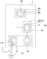
도 1a 내지 도 1c는 본 발명에 따른 소자제거장치를 구성 및 작동과정을 보여주는 평면도이다.
도 2a 및 도 2b는 각각 도 1의 소자제거장치에 사용되는 플레이트의 예들을 보여주는 개념도들이다.
도 3a 및 도 3b는 각각 도 1의 소자제거장치 중 소자제거부의 구성 및 작동과정을 보여주는 일부단면도이다.
도 4a 및 도 4b는 각각 도 1의 소자제거장치 중 소자제거부의 구성 및 작동과정을 보여주는 평면도이다.
도 5는 도 1의 도 1의 소자제거장치의 변형례를 보여주는 평면도이다.FIGS. 1A to 1C are plan views showing the construction and operation of an element removing apparatus according to the present invention.
2A and 2B are conceptual diagrams showing examples of plates used in the device removing apparatus of FIG. 1, respectively.
FIGS. 3A and 3B are partial cross-sectional views illustrating the configuration and operation of the device removing portion of the device removing device of FIG. 1, respectively.
4A and 4B are plan views showing the configuration and operation of the device removing unit of the device removing apparatus of FIG. 1, respectively.
FIG. 5 is a plan view showing a modification of the element removing apparatus of FIG. 1 of FIG. 1;
이하 본 발명에 따른 소자제거모듈 및 그를 가지는 소자제거장치에 관하여 첨부된 도면을 참조하여 상세히 설명하면 다음과 같다.Hereinafter, an element removing module according to the present invention and an element removing apparatus having the same will be described in detail with reference to the accompanying drawings.
본 발명에 따른 소자제거장치는 도 1 내지 도 1c에 도시된 바와 같이, 복수의 소자(1)들이 부착되어 적재된 복수의 플레이트(10)들이 적재된 플레이트적재부(100)와; 플레이트(10)로부터 제거될 소자(1)를 흡입하여 제거하는 하나 이상의 소자제거부(400)와; 소자제거부(400)가 플레이트(10)로부터 제거될 소자(1)를 흡입할 수 있도록 플레이트적재부(100)로부터 전달받은 플레이트(10)를 소자제거부(400)에 대하여 상대이동시키는 하나 이상의 X-Y테이블(300)과; 플레이트적재부(100) 및 X-Y테이블(300) 사이에서 플레이트(10)를 이송하는 하나 이상의 플레이트이송부(200)를 포함한다.1 to 1C, a device removing apparatus according to the present invention includes a
먼저 상기 플레이트(10)에 부착되어 적재되는 소자(1)는 엘이디소자, 반도체소자 등 테이프에 부착되어 이송될 수 있는 소자이면 어떠한 소자도 가능하다.First, the
여기서 상기 플레이트(10)에 적재된 소자(1)는 검사장치에 의하여 미리 검사되어 제거될지 여부가 결정된 상태에 있으며, 도시하지 않았지만 플레이트(10)의 각 위치에 따라서 소자(1)의 제거여부에 대한 정보가 유선통신 또는 무선통신 등을 통하여 소자제거장치에 전달될 수 있다.Here, it is determined whether or not the
한편 소자(1)가 부착되어 적재되는 플레이트(10)는 소자(1)가 부착되어 적재될 수 있는 부재이면 어떠한 구성도 가능하며, 도 2a 및 도 2b에 도시된 바와 같이, 웨이퍼링, 직사각형의 플레이트 등 다양한 종류를 가진다.On the other hand, the
상기 플레이트(10)의 예로서, 소자(1)가 부착되는 테이프를 구비한 웨이퍼링이 사용될 수 있으며, 도 2a에 도시된 바와 같이, 각 소자별로 절단된 웨이퍼가 상면에 부착되도록 표면에 접착성을 가지는 테이프(11)와; 테이프(11)가 결합되는 제1결합링(12)과, 제1결합링(12)에 결합된 테이프(11)를 외경방향으로 장력을 가하여 테이프(11)를 외경방향으로 변형시켜 각 소자(1)들을 미세하게 이격시키는 제2결합링(13)을 포함하여 구성될 수 있다.As an example of the
또한 상기 플레이트(10)의 다른 예로서, 소자(1)가 부착되는 테이프를 구비한 직사각형의 플레이트가 사용될 수 있으며, 도 2b에 도시된 바와 같이, 웨이퍼링(10)과 유사한 테이프(11)와, 테이프(11)를 고정시키면서 LOT번호, 분류등급 등의 표식이 있는 지지부재(14)를 포함하여 구성될 수 있다.As another example of the
상기 플레이트적재부(100)는 장치의 프레임을 형성하는 본체(2)에 설치되어, 복수의 소자(1)들이 부착되어 적재된 복수의 플레이트(10)들이 적재되는 구성으로서 다양한 구성이 가능하다.The
예로서, 상기 플레이트적재부(100)는, 복수의 플레이트(10)들이 적재되는 하나 이상의 카세트(110)들을 포함할 수 있다.As an example, the
그리고 상기 카세트(110)는, 후술하는 플레이트이송부(200)에 대한 플레이트전달이 용이하도록 상하로 이동가능하게 설치될 수 있다.The
한편 상기 플레이트적재부(100)는 복수의 카세트(110)가 평행하게 복수개로 설치될 수 있다.Meanwhile, a plurality of
이때 상기 플레이트적재부(100)는, 복수의 카세트(110)들을 구분하여, 제거될 소자(1)가 포함된 복수의 플레이트(10)들이 적재되는 로딩카세트부(101) 및 소자제거부(400)에 의하여 제거될 소자(1)가 제거된 플레이트(10)가 적재되는 언로딩카세트부(102)로 구분하여 구성될 수 있다.The
한편 플레이트적재부(100)에는 카세트(110)가 작업자에 의하여 수동으로 또는 로봇 등에 의하여 자동으로 교체될 수 있다.On the other hand, the
상기 플레이트이송부(200)는, 플레이트적재부(100) 및 X-Y테이블(300) 사이에서 플레이트(10)를 이송하는 구성으로서, 플레이트(10)의 이동방식, 플레이트적재부(100)와의 플레이트전달, X-Y테이블(300)와의 플레이트전달 등 플레이트(10)의 전달방식에 따라서 그 숫자 및 구성이 다양하게 구성될 수 있다.The
예로서, 상기 플레이트이송부(200)는 플레이트(10)가 안착되는 플레이트안착부(210)와, 플레이트적재부(100) 및 플레이트안착부(210) 사이 또는 X-Y테이블(300) 및 플레이트안착부(210) 사이에서 플레이트(10)를 이동시키는 하나 이상의 플레이트이동부(220)를 포함할 수 있다.For example, the
상기 플레이트안착부(210)는 플레이트적재부(100)와의 플레이트전달, X-Y테이블(300)과의 플레이트전달시 플레이트(10)가 안착될 수 있은 구성이면 어떠한 구성도 가능하다.The
여기서 상기 플레이트안착부(210)는 플레이트적재부(100)와의 플레이트전달, X-Y테이블(300)와의 플레이트전달시 플레이트(10)의 이동을 가이드하는 가이드부재(211)가 추가로 설치될 수 있다.The
상기 플레이트이동부(220)는 플레이트적재부(100)와의 플레이트전달, X-Y테이블(300)와의 플레이트전달시 플레이트(10)를 이동시키기 위한 구성으로서, 플레이트의 이동방식 및 플레이트(10)의 전달방식에 따라서 그 숫자 및 구성이 다양하게 구성될 수 있다.The
상기 플레이트이동부(220)는 플레이트(10)를 밀어서 이동하는 푸시방식, 플레이트(10)를 그립하여 이동하는 그립방식 등 다양한 방식에 의하여 플레이트(10)를 이동시킬 수 있다.The
그리고 상기 플레이트이동부(220)는 플레이트적재부(100)와의 플레이트전달, X-Y테이블(300)와의 플레이트전달을 고려하여 그 설치 위치 및 설치개수는 적절하게 선택될 수 있다. The
상기 플레이트이동부(220)는 플레이트(10)를 그립하여 이동시키는 그립방식을 채택할 수 있으며, 예로서, 플레이트안착부(210)와 결합되어 플레이트(10)를 그립하여 선형이동에 의하여 플레이트(10)를 이동시키도록 구성될 수 있다.The
즉, 상기 플레이트이동부(220)는 플레이트(10)를 그립하는 그립부(221)와, 플레이트적재부(100) 및 플레이트안착부(210)를 연결하는 방향으로 그립부(221)를 선형이동시키는 선형구동부(미도시)를 포함할 수 있다.The
상기 그립부(221)는 플레이트(10)를 그립할 수 있는 구성이면 어떠한 구성도 가능하다.The
상기 선형구동부(미도시)는 플레이트적재부(100) 및 플레이트안착부(210)를 연결하는 방향으로 그립부(221)를 선형이동시킬 수 있는 구성이면 어떠한 구성도 가능하다.The linear driving unit (not shown) may have any structure as long as it can linearly move the
한편 상기 플레이트이송부(200)는, 플레이트적재부(100) 및 X-Y테이블(300) 사이에 설치될 수 있으며, 이때 플레이트이송부(200)는, 도 1b에 도시된 바와 같이, 플레이트적재부(100)로부터 플레이트(10)를 인출하여 플레이트안착부(210)에 안착시킨 후, 도 1c에 도시된 바와 같이, 플레이트(10)가 안착된 플레이트안착부(210)를 180°회전시켜 X-Y테이블(300)로 플레이트(10)를 전달할 수 있다.The
한편 상기 플레이트이송부(200)가 하나로 구성되고, 소자제거를 마친 플레이트(10)가 적재된 X-Y테이블(300)로 소자제거를 마친 새로운 플레이트(10)를 전달하고자 하는 경우, X-Y테이블(300)에 적재된 플레이트(10)를 제거하여야만 X-Y테이블(300)로 소자제거를 마친 새로운 플레이트(10)의 적재가 가능하다.When the
이 경우 상기 플레이트이송부(200)가 X-Y테이블(300)에 적재된 플레이트(10)를 제거한 후에 X-Y테이블(300)로 소자제거를 마친 새로운 플레이트(10)의 적재하게 되므로 플레이트(10)의 재적재 시간이 추가되어 소자제거 공정시간이 증가하는 문제점이 있다.In this case, since the
따라서 상기 플레이트이송부(200)는 소자제거를 마친 플레이트(10)가 적재된 X-Y테이블(300)로 전달할 때, 소자제거를 마친 플레이트(10)를 임시로 위치시키는 플레이트버퍼부(미도시)를 추가로 포함할 수 있다.Therefore, when the
상기 플레이트버퍼부는 소자제거를 마친 플레이트(10)를 임시로 위치시키는 구성으로서 다양한 구성이 가능하다.The plate buffer unit may be configured to temporarily position the
예로서, 상기 플레이트버퍼부는, X-Y테이블(300) 및 플레이트이송부(200) 사이에서 왕복이동에 의하여 X-Y테이블(300)에 안착된 플레이트(10)를 픽업하여 플레이트안착부(210)에 플레이스하는 플레이트픽업부와, 플레이트픽업부를 X-Y테이블(300) 및 플레이트이송부(200) 사이에서 왕복이동시키는 픽업부이송부를 포함할 수 있다.For example, the plate buffer part picks up the
상기 플레이트픽업부는 플레이트(10)를 픽업하기 위한 구성으로서 상측으로 들어올리거나 그립하여 선형이동시키는 등 플레이트(10)의 픽업방식에 따라서 다양한 구성이 가능하다.The plate pick-up unit may be configured to pick up the
상기 X-Y테이블(300)은, 소자제거부(400)가 플레이트(10)로부터 제거될 소자(1)를 흡입할 수 있도록 플레이트적재부(100)로부터 전달받은 플레이트(10)를 소자제거부(400)에 대하여 상대이동시키는 구성으로서 플레이트(10)의 이동방식에 따라서 다양한 구성이 가능하다.The XY table 300 is used to remove the
예로서, 상기 X-Y테이블(300)은, 플레이트(10)를 그립하는 그립부가 설치된 테이블부와; 테이블부를 직교하는 2개의 축방향으로 선형구동하는 테이블구동부를 포함할 수 있다.For example, the X-Y table 300 includes a table portion provided with a grip portion for gripping the
또한 상기 테이블구동부는 테이블부의 상면과 수직을 이루는 회전축을 중심으로 테이블부를 회전구동하는 θ구동부를 추가로 포함할 수 있다.The table driving unit may further include a &thetas; driving unit for rotationally driving the table unit about a rotational axis that is perpendicular to the top surface of the table unit.
한편 상기 플레이트(10)의 종류가 다양하게 변경될 수 있는바, 다양한 종류의 플레이트(10)의 사용이 가능하도록, 테이블부는, 플레이트의 종류변경에 따라서 변경된 플레이트(10)의 그립 및 안착이 가능하도록 일부가 교체가능하도록 설치됨이 바람직하다.Meanwhile, the type of the
또한 상기 X-Y테이블(300)은, 도 3a 및 도 3b에 도시된 바와 같이, 소자제거부(400)가 플레이트(10)로부터 소자(1)를 제거하는 제거위치(P)에 대응하여 소자제거부(400)가 플레이트(10)로부터 소자(1)를 제거할 때 플레이트(10)의 테이프(11)를 소자제거부(400) 쪽으로 밀어올리는 니들핀(390)이 설치될 수 있다.3A and 3B, the XY table 300 is formed in such a manner that the
상기 소자제거부(400)는, 플레이트(10)로부터 제거될 소자(1)를 흡입하여 제거하는 구성으로서, 진공압을 이용하여 플레이트(10)에 부착되어 적재된 소자(1)를 제거할 수 있는 구성이면 어떠한 구성도 가능하다.The
일예로서, 상기 소작제거부(400)는, 진공압발생장치(미도시)와 소자(1)를 진공압에 의하여 흡입하는 흡입헤드(410)를 포함할 수 있다.As an example, the throttling
상기 흡입헤드(410)는 공압전달선(미도시)에 의하여 진공압발생장치와 연결됨으로써 진공압에 의하여 소자(1)를 흡입하는 구성으로서 내부에 진공유로(411)가 형성되도록 하나 이상의 부재로 구성되는 등 다양한 구성이 가능하다.The
이때 상기 흡입헤드(410)는 진공압에 의하여 소자(1)를 흡입하는바 진공유로(411)를 통하여 소자(1)가 흡입될 수 있도록 진공유로(411)의 단면적이 소자(1)의 크기보다 크게 형성됨이 바람직하다.The
한편 상기 소자제거부(400)는, 흡입헤드(410)와 진공압발생장치 사이의 진공압유로에 설치되어 흡입헤드(410)에 의하여 흡입된 소자(1)를 수집하는 소자수집부(미도시)를 포함할 수 있다.Meanwhile, the
상기 소자흡입부는 진공압유로에 설치되어 소자(1)를 수집할 수 있는 구성이면 어떠한 구성이 가능하다.The device suction unit can be configured in any configuration as long as it is installed in a vacuum pump and can collect the
한편 상기 소자제거부는, X-Y테이블(300)에 적재된 플레이트(10)에서 제거될 소자(1)에 대한 이미지를 획득하는 이미지획득부(480)를 추가로 포함할 수 있다.Meanwhile, the device removing unit may further include an
상기 이미지획득부(480)는, X-Y테이블(300)에 적재된 플레이트(10)에서 제거될 소자(1)에 대한 이미지를 획득하는 구성으로서 카메라 등 다양한 구성이 가능하며, X-Y테이블(200)에 적재된 플레이트(10)에서 소자(1)가 제거될 제거위치(P)에 대응되어 위치됨이 바람직하다.The
즉, 상기 이미지획득부(480)에 의하여 획득된 이미지를 분석하여 제거여부를 결정하여 플레이트(10)의 이동없이 바로 소자(1)를 제거함으로써 플레이트(10)의 이동에 기인하는 추가 오차발생을 방지할 수 있다.That is, the image obtained by the
또한 상기 이미지획득부(480)는, 제거될 소자(1)가 적재된 플레이트(10)를 X-Y테이블(300)에 의한 기계적 이동의 결과로 제거위치(P)와 오차가 발생될 가능성이 높은바, 플레이트(10)의 이동 후 제거될 소자(1)가 제거위치(P)에 위치되었는지 여부를 이미지획득부(480)에 의하여 획득된 이미지를 분석하여 확인하고 오차가 있는 경우 그 오차를 보정한 후에 흡입헤드(410)에 의하여 소자(1)를 제거하도록 하는데 사용될 수 있다.Also, the
한편 상기 소자제거부(400)의 흡입헤드(410)는 X-Y테이블(200)에 적재된 플레이트(10)에서 소자(1)가 제거될 제거위치(P)에서 X-Y테이블(200) 및 이미지획득부(480) 사이에 위치됨이 바람직하다.Meanwhile, the
이 경우, 상기 이미지획득부(480)이 플레이트(10)에 적재된 소자(1)에 대한 이미지의 획득이 가능하도록, 이미지획득부(480)는, 소자제거부(400)가 X-Y테이블(200) 및 이미지획득부(480) 사이에 위치되었음에도 불구하고 이미지획득부(480)가 소자(1)에 대한 이미지를 획득하도록 하는 이미지획득보조수단을 포함할 수 있다.In this case, the
상기 이미지획득보조수단은 이미지획득부(480)는, 소자제거부(400)가 X-Y테이블(200) 및 이미지획득부(480) 사이에 위치되었음에도 불구하고 이미지획득부(480)가 소자(1)에 대한 이미지 획득을 가능하도록 하는 구성으로서 다양한 구성이 가능하다.The
상기 이미지획득보조수단의 일예로서, 도 3a 내지 도 4b에 도시된 바와 같이 구성될 수 있다.As an example of the image acquisition assistant means, it can be configured as shown in Figs. 3A to 4B.
상기 이미지획득보조수단의 일예로서, 흡입헤드(410)가, X-Y테이블(200)에 적재된 플레이트(10)의 표면에 대하여 수직을 이루어 관통된 관통공(412)이 형성되며 관통공(412)과 연결됨과 아울러 진공압발생장치를 연결하는 진공유로(411)가 형성된 본체부(413)와; 본체부(413)와 결합되어 관통공(412) 중 플레이트(10)의 반대쪽 제2끝단(412a)을 복개하는 복개부재(420)와; 이미지획득부(480)가 소자(1)에 대한 이미지를 획득할 때 관통공(412)의 제2끝단(412b)을 개방하고, 흡입헤드(410)에 의하여 소자(1)를 흡입할 때 관통공(412)의 제2끝단(412b)을 복개하도록 복개부재(420)를 이동시키는 복개부재구동부(430)를 포함함으로써, 이미지획득보조수단이 구현될 수 있다.As an example of the image acquisition assistant means, the
상기 본체부(413)는 X-Y테이블(200)에 적재된 플레이트(10)의 표면에 대하여 수직을 이루어 관통된 관통공(412)이 형성되며 관통공(412)과 연결됨과 아울러 진공압발생장치를 연결하는 진공유로(411)가 형성는 구성으로서, 하나의 부재 또는 복수의 부재들로 구성될 수 있다.The
상기 복개부재(420)는 이미지획득부(480)가 소자(1)에 대한 이미지를 획득할 때 관통공(412)의 제2끝단(412b)을 개방하고, 흡입헤드(410)에 의하여 소자(1)를 흡입할 때 관통공(412)의 제2끝단(412b)을 복개하도록 이동되는 부재로서 다양한 구성이 가능하다.The clogging
특히 상기 복개부재(420)는 선형이동, 회전이동, 또는 그 조합 등 다양한 방식에 의하여 이동, 특히 회전에 의하여 관통공(412)의 제2끝단(412b)을 개폐할 수 있다.Particularly, the
상기 복개부재구동부(430)는, 복개부재(420)의 이동을 구동하기 위한 구성으로서 그 구동방식에 따라서 다양한 구성이 가능하며, 예로서, 회전모터(431)와, 회전모터(431)의 회전축(431a)에 결합된 구동풀리(432)와, 복개부재(420)와 고정결합된 회전축(421)에 결합된 종동풀리(433)와, 구동풀리(432) 및 종동풀리(433)를 연결하여 회전력을 전달하는 벨트(434)를 포함하여 구성될 수 있다.The cover
상기 이미지획득보조수단의 다른 예로서, 앞서 설명한 바와 같이, 복개부재(420)를 고정시키고, 상기 복개부재(420)는, 본체부(413)와 결합되어 관통공(412) 중 플레이트(10)의 반대쪽 제2끝단(412b)을 복개하며 이미지획득부(480)가 소자(1)에 대한 이미지를 획득할 수 있도록 빛의 투과가 가능한 투명재질을 가지도록 구성됨으로써, 이미지획득보조수단이 구현될 수 있다. As another example of the image acquisition assistant means, as described above, the
한편 상기 이미지획득부(480)가 소자(1) 및 그 주변에 대한 이미지획득이 용이하도록, 관통공(412)의 제2끝단(412b)은 플레이트(10)를 향하는 제1끝단(412a)의 크기보다 더 큰 것이 바람직하다.The
즉, 상기 관통공(412)는 원기둥, 다각기둥의 형상보다는 제2끝단(412b)으로 가면서 그 내경이 커지도록 뿔대 형상을 가지는 것이 바람직하다.That is, it is preferable that the through-
상기와 같이 흡입헤드(410)가 관통공(412) 및 흡입헤드(410)의 존재에도 불구하고, 소자제거부(400)는 이미지획득부(480)가 소자(1)에 대한 이미지를 획득할 수 있는 복개부재(420)를 구비함(복개부재(420)의 회전을 통한 관통공(412)의 개방 및 폐쇄, 투명한 복개부재(420) 등)으로써, 이미지획득부(480)에 의하여 획득된 이미지를 획득하여 획득된 이미지를 분석하여 소자제거공정을 보다 원활하게 수행할 수 있다.Despite the presence of the through-
한편 상기와 같은 구성을 가지는 소자제거부는 앞서 설명한 소자제거장치의 구성 일부로서 사용되는 것 이외에, 소자(1)가 부착되어 적재된 플레이트(10)를 사용하는 어떠한 형태의 소자핸들러에도 적용가능함은 물론이다.Meanwhile, the element removing unit having the above-described structure may be applied to any type of element handler using the
특히 상기 소자제거부는 소자검사를 위한 검사모듈을 구비한 소자핸들러, 엘이디소자의 다이본딩을 위한 모듈이 포함된 소자핸들러 등 다양한 형태의 소자핸들러에 포함되어 적용될 수 있음은 물론이다.In particular, the device removing unit may be included in various types of device handlers such as a device handler having an inspection module for inspecting the device, a device handler including a module for die bonding of the LED device, and the like.
한편 상기와 같은 구성을 가지는 소자제거장치는, 그 구성에 있어서, 소자제거공정의 처리속도를 높이기 위하여, 도 5에 도시된 바와 같이, 복수의 X-Y테이블(300)을 포함할 수 있다.On the other hand, the element removing apparatus having the above-described structure may include a plurality of X-Y tables 300 as shown in FIG. 5 in order to increase the processing speed of the element removing process.
여기서 상기 소자제거장치는 복수의 X-Y테이블(300) 각각에 대응되어 복수의 플레이트이송부(200)를 포함할 수 있다.The device removing device may include a plurality of
또한 상기 소자제거장치는 복수의 X-Y테이블(300) 각각에 대응되어 복수의 플레이트적재부(100)를 포함할 수 있다.The device removing apparatus may include a plurality of
이하 상기와 같은 구성을 가지는 소자제거장치의 작동에 관하여 첨부된 도면을 참조하여 상세히 설명하면 다음과 같다.Hereinafter, the operation of the device for removing elements having the above-described structure will be described in detail with reference to the accompanying drawings.
먼저 플레이트적재부(100) 및 X-Y테이블(300) 사이에서 플레이트이송부(200)에 의한 플레이트(10)의 교환은 플레이트(10)의 이송방식 및 플레이트이송부(200)의 구성에 따라서 다양하게 이루어질 수 있다.The exchange of the
예로서, 제거될 소자(1)가 포함된 플레이트(10)는 도 1a 내지 도 1c에 도시된 바와 같이, 플레이트이송부(200)에 의하여 플레이트적재부(100)로부터 인출되어 180° 회전 등 다양한 형태로 X-Y테이블(300)로 전달된다.For example, the
이때 상기 X-Y테이블(300)에는 제거될 소자(1)가 모두 제거된 플레이트(10)가 존재하는바, 제거될 소자(1)가 포함된 새로운 플레이트(10)의 전달 전에 제거될 소자(1)가 모두 제거된 플레이트(10)가 플레이트이송부(200)에 의하여 플레이트적재부(100)로 전달된다.In this case, the XY table 300 includes a
한편 상기 X-Y테이블(300)로의 플레이트전달, X-Y테이블(300)에서의 플레이트제거가 각각 플레이트이송부(200)에 의하여 수행되는 경우 플레이트적재부(100) 및 X-Y테이블(300) 사이에서 플레이트교환에 소요되는 시간으로 인하여 장치의 처리속도를 저하시킬 수 있다.Meanwhile, when plate transfer to the XY table 300 and plate removal to the XY table 300 are performed by the
이에 상기 플레이트이송부(200)는 마친 플레이트가 적재된 상기 X-Y테이블로 전달할 때, 소자제거를 마친 플레이트를 임시로 위치시키는 플레이트버퍼부를 추가로 포함함으로써 플레이트적재부(100) 및 X-Y테이블(300) 사이에서 플레이트교환이 빠르게 이루어질 수 있다.The
한편 상기 X-Y테이블(300)에 안착된 플레이트(10)는 다음과 같은 과정을 거쳐 소자제거부(400)에 의하여 제거될 소자(1)가 제거된다.On the other hand, the
먼저 앞서 설명한 플레이트이송부(200)에 의하여 X-Y테이블(300)로 플레이트(10)가 전달되면, X-Y테이블(300)은, 도 3a에 도시된 바와 같이, 플레이트(10)를 고정한 상태에서 프로그램 등에 의하여 입력된 제거될 소자(1)들을 순차적으로 제거위치(P)에 위치시킨다.3A, when the
그리고 상기 소자제거부(400)는 X-Y테이블(300)에 의하여 제거될 소자(1)가 제거위치(P)에 위치되면 흡입에 의하여 소자(1)를 플레이트(10)로부터 제거하게 된다.The
한편 제거될 소자(1)가 X-Y테이블(300)에 의하여 제거위치(P)에 위치될 때 X-Y테이블(300)의 구성상의 기계적 오차로 인하여, 제거될 소자(1)가 제거위치(P)에 정확하게 위치되지 않을 수 있다.On the other hand, when the
그리고 제거될 소자(1)가 제거위치(P)에 정확하게 위치되지 않는 경우. 소자(1)의 흡입을 실패하거나, 다른 소자(1)가 흡입하는 등 오작동을 일으킬 수 있다.And the
이에 상기 소자제거부(1)는 제거위치(P)에 위치된 소자(1)에 대한 이미지를 이미지획득부(480)에 의하여 획득하고, 제어부(미도시)에 의하여 제거될 소자(1)가 제거위치(P)에 정확하게 위치되지 않는 경우 그 위치를 보정함으로써 제거될 소자(1)가 플레이트(10)로부터 안정적으로 제거할 수 있다.The
또한 상기 이미지획득부(480)는 소자제거부(1)에 의하여 소자(1)가 제거된 후, 재차 소자(1)에 대한, 보다 정확하게는 제거될 소자(1)가 제거된 플레이트(10)의 일부에 대한 이미지를 획득하고, 제어부는 획득된 이미지를 분석하여 소자(1)가 제거된 것으로 판단하면, 소자제거공정 또는 플레이트교환 등 후속공정을 수행하도록 제어할 수 있다.
The
이상은 본 발명에 의해 구현될 수 있는 바람직한 실시예의 일부에 관하여 설명한 것에 불과하므로, 주지된 바와 같이 본 발명의 범위는 위의 실시예에 한정되어 해석되어서는 안 될 것이며, 위에서 설명된 본 발명의 기술적 사상과 그 근본을 함께 하는 기술적 사상은 모두 본 발명의 범위에 포함된다고 할 것이다.It will be apparent to those skilled in the art that various modifications and variations can be made in the present invention without departing from the spirit or scope of the invention as defined in the appended claims. It is to be understood that both the technical idea and the technical spirit of the invention are included in the scope of the present invention.
100 : 플레이트 적재부 200 : 플레이트이송부
300 : X-Y테이블 400 : 소자제거부100: Plate loading part 200: Plate feeding part
300: XY table 400: element removal
Claims (31)
플레이트로부터 제거될 소자를 흡입하여 제거하는 하나 이상의 소자제거부와;
상기 소자제거부가 플레이트로부터 제거될 소자를 흡입할 수 있도록 상기 플레이트적재부로부터 전달받은 플레이트를 상기 소자제거부에 대하여 상대이동시키는 하나 이상의 X-Y테이블과;
상기 플레이트적재부 및 상기 X-Y테이블 사이에서 플레이트를 이송하는 하나 이상의 플레이트이송부를 포함하는 것을 특징으로 하는 소자제거장치.A plate stacking portion on which a plurality of stacked plates are stacked;
At least one element removing unit for sucking and removing elements to be removed from the plate;
One or more XY tables for moving the plate transferred from the plate loading part relative to the element removing part so that the element removing part can suck the element to be removed from the plate;
And one or more plate transfer sections for transferring the plate between the plate loading section and the XY table.
상기 플레이트적재부는,
제거될 소자가 포함된 복수의 플레이트들이 적재되는 로딩카세트부와,
상기 소자제거부에 의하여 제거될 소자가 제거된 플레이트가 적재되는 언로딩카세트부를 포함하는 것을 특징으로 하는 소자제거장치.The method according to claim 1,
The plate-
A loading cassette part on which a plurality of plates including elements to be removed are loaded,
And an unloading cassette unit on which the plate from which the element to be removed by the element removing unit is removed is loaded.
상기 플레이트적재부는, 복수의 플레이트들이 적재되는 하나 이상의 카세트들을 포함하는 것을 특징으로 하는 소자제거장치.The method according to claim 1,
Wherein the plate stacking portion comprises one or more cassettes on which a plurality of plates are stacked.
상기 카세트는, 상하로 이동가능하게 설치된 것을 특징으로 하는 소자제거장치.34. The method of claim 33,
Wherein the cassette is provided so as to be movable up and down.
상기 플레이트이송부는, 플레이트가 안착되는 플레이트안착부와, 상기 플레이트적재부 및 상기 플레이트안착부 사이 또는 상기 X-Y테이블 및 상기 플레이트안착부 사이에서 플레이트를 이동시키는 하나 이상의 플레이트이동부를 포함하는 것을 특징으로 하는 소자제거장치.The method according to claim 1,
Wherein the plate conveying portion includes a plate seating portion on which the plate is seated and at least one plate moving portion for moving the plate between the plate stacking portion and the plate seating portion or between the XY table and the plate seating portion Device removing device.
상기 플레이트이동부는 상기 플레이트안착부와 결합되어 플레이트를 그립하여 선형이동에 의하여 플레이트를 이동시키는 것을 특징으로 하는 소자제거장치.The method of claim 5,
Wherein the plate moving part is engaged with the plate seating part to grip the plate and move the plate by linear movement.
상기 플레이트이송부는, 상기 플레이트적재부 및 상기 X-Y테이블 사이에 설치되며,
상기 플레이트이송부는, 상기 플레이트적재부로부터 플레이트를 인출하여 상기 플레이트안착부에 안착시킨 후, 플레이트가 안착된 상기 플레이트안착부를 180°회전시켜 상기 X-Y테이블로 플레이트를 전달하는 것을 특징으로 하는 소자제거장치.The method according to claim 1,
Wherein the plate conveying portion is provided between the plate mounting portion and the XY table,
Wherein the plate conveying unit conveys the plate to the XY table by rotating the plate seating part on which the plate is placed by 180 DEG after drawing the plate from the plate loading part and placing the plate on the plate seating part, .
상기 플레이트이송부는 소자제거를 마친 플레이트가 적재된 상기 X-Y테이블로 전달할 때, 소자제거를 마친 플레이트를 임시로 위치시키는 플레이트버퍼부를 추가로 포함하는 것을 특징으로 하는 소자제거장치.The method according to claim 1,
Further comprising a plate buffer part for temporarily placing the plate after the element removal when the plate transfer part transfers the XY table on which the element-removed plate is mounted.
상기 플레이트버퍼부는, 상기 X-Y테이블 및 상기 플레이트이송부 사이에서 왕복이동에 의하여 상기 X-Y테이블에 안착된 플레이트를 픽업하여 상기 플레이트안착부에 플레이스하는 플레이트픽업부와, 상기 플레이트픽업부를 상기 X-Y테이블 및 상기 플레이트이송부 사이에서 왕복이동시키는 픽업부이송부를 포함하는 것을 특징으로 하는 소자제거장치.The method of claim 8,
The plate buffer unit includes a plate pick-up unit for picking up a plate seated on the XY table by reciprocating movement between the XY table and the plate conveyance unit and placing the plate on the plate seating unit, And a pick-up part for reciprocating between the feeding parts.
상기 X-Y테이블은,
플레이트를 그립하는 그립부가 설치된 테이블부와; 상기 테이블부를 직교하는 2개의 축방향으로 선형구동하는 테이블구동부를 포함하는 것을 특징으로 하는 소자제거장치.The method according to claim 1,
In the XY table,
A table portion provided with a grip portion for gripping the plate; And a table driving unit for linearly driving the table unit in two axial directions orthogonal to each other.
상기 테이블구동부는 상기 테이블부의 상면과 수직을 이루는 회전축을 중심으로 상기 테이블부를 회전구동하는 θ구동부를 추가로 포함하는 것을 특징으로 하는 소자제거장치.The method of claim 10,
Wherein the table driving unit further comprises a [theta] driving unit that rotationally drives the table unit about a rotation axis perpendicular to an upper surface of the table unit.
상기 테이블부는 플레이트의 종류변경에 따라서 변경된 플레이트의 그립 및 안착이 가능하도록 일부가 교체가능하도록 설치된 것을 특징으로 하는 소자제거장치.The method of claim 10,
Wherein the table portion is provided so that a part of the table portion can be replaced so as to enable gripping and seating of the changed plate according to the type of the plate.
상기 X-Y테이블은,
상기 소자제거부가 플레이트로부터 소자를 제거하는 제거위치에 대응하여 상기 소자제거부가 플레이트로부터 소자를 제거할 때 플레이트의 테이프를 상기 소자제거부 쪽으로 밀어올리는 니들핀이 설치된 것을 특징으로 하는 소자제거장치.The method according to claim 1,
In the XY table,
And a needle pin is provided for pushing up the tape of the plate toward the element removing portion when the element removing portion removes the element from the plate corresponding to the removing position where the element removing portion removes the element from the plate.
상기 소자제거부는, 진공압발생장치와 연결되어 상기 소자를 진공압에 의하여 흡입하는 흡입헤드를 포함하는 것을 특징으로 하는 소자제거장치.The method according to any one of claims 1 to 13,
Wherein the device removing unit includes a suction head connected to the vacuum pressure generating device and sucking the device by vacuum pressure.
상기 소자제거부는, 상기 흡입헤드와 상기 진공압발생장치 사이의 진공압유로에 설치되어 상기 흡입헤드에 의하여 흡입된 소자를 수집하는 소자수집부를 포함하는 것을 특징으로 하는 소자제거장치.15. The method of claim 14,
Wherein the element removing unit comprises a device collecting unit installed in a vacuum passage between the suction head and the vacuum pressure generating device to collect the suctioned by the suction head.
상기 소자제거부는, 상기 X-Y테이블에 적재된 플레이트에서 제거될 소자에 대한 이미지를 획득하는 이미지획득부를 추가로 포함하는 것을 특징으로 하는 소자제거장치.15. The method of claim 14,
Wherein the device removing unit further comprises an image obtaining unit that obtains an image of a device to be removed from the plate stacked on the XY table.
상기 이미지획득부는 상기 X-Y테이블에 적재된 플레이트에서 소자가 제거될 제거위치에 대응되어 위치되며,
상기 소자제거부의 흡입헤드는 상기 X-Y테이블에 적재된 플레이트에서 소자가 제거될 제거위치에서 상기 X-Y테이블 및 상기 이미지획득부 사이에 위치되며,
상기 흡입헤드는,
상기 X-Y테이블에 적재된 플레이트의 표면에 대하여 수직을 이루어 관통된 관통공이 형성되며 상기 관통공과 연결됨과 아울러 상기 진공압발생장치를 연결하는 진공유로가 형성된 본체부와;
상기 본체부와 결합되어 상기 관통공 중 상기 플레이트의 반대쪽 제2끝단을 복개하는 복개부재와;
상기 이미지획득부가 소자에 대한 이미지를 획득할 때 상기 관통공의 제2끝단을 개방하고, 상기 흡입헤드에 의하여 소자를 흡입할 때 상기 관통공의 제2끝단을 복개하도록 상기 복개부재를 이동시키는 복개부재구동부를 포함하는 것을 특징으로 하는 소자제거장치.18. The method of claim 16,
Wherein the image acquiring unit is positioned corresponding to a removal position at which a device is to be removed from the plate loaded in the XY table,
Wherein the suction head of the element removing unit is located between the XY table and the image obtaining unit at a removal position where elements are to be removed from the plate loaded on the XY table,
The suction head includes:
A main body part having a through hole formed perpendicularly to the surface of the plate mounted on the XY table and connected to the through hole and having a vacuum flow path connecting the vacuum pressure generator;
A cover member coupled with the body portion to cover the second end of the through hole, the second end being opposite to the plate;
Wherein the image acquiring unit opens the second end of the through-hole when acquiring an image for the element, and when the element is sucked by the suction head, the cover is moved to cover the second end of the through- And a member driving unit.
상기 복개부재는, 회전에 의하여 상기 관통공의 제2끝단을 개폐하는 것을 특징으로 하는 소자제거장치.18. The method of claim 17,
Wherein the closure member opens and closes the second end of the through hole by rotation.
상기 복개부재구동부는, 회전모터와, 상기 회전모터의 회전축에 결합된 구동풀리와, 상기 복개부재와 고정결합된 회전축에 결합된 종동풀리와, 상기 구동풀리 및 종동풀리를 연결하여 회전력을 전달하는 벨트를 포함하는 것을 특징으로 하는 소자제거장치.18. The method of claim 17,
The cover member driving unit includes a rotating motor, a driving pulley coupled to a rotating shaft of the rotating motor, a driven pulley coupled to a rotating shaft fixedly coupled to the covering member, and a driving pulley coupled to the driving pulley and the driven pulley, And a belt.
상기 관통공의 제2끝단은 상기 플레이트를 향하는 제1끝단의 크기보다 더 큰 것을 특징으로 하는 소자제거장치. 18. The method of claim 17,
Wherein the second end of the through-hole is larger than the first end of the through-hole facing the plate.
상기 이미지획득부는 상기 X-Y테이블에 적재된 플레이트에서 소자가 제거될 제거위치에 대응되어 위치되며,
상기 소자제거부의 흡입헤드는 상기 X-Y테이블에 적재된 플레이트에서 소자가 제거될 제거위치에서 상기 X-Y테이블 및 상기 이미지획득부 사이에 위치되며,
상기 흡입헤드는,
상기 X-Y테이블에 적재된 플레이트의 표면에 대하여 수직을 이루어 관통된 관통공이 형성되며 상기 관통공과 연결됨과 아울러 상기 진공압발생장치를 연결하는 진공유로가 형성된 본체부와;
상기 본체부와 결합되어 상기 관통공 중 상기 플레이트의 반대쪽 제2끝단을 복개하며 상기 이미지획득부가 소자에 대한 이미지를 획득할 수 있도록 빛의 투과가 가능한 투명재질을 가지는 복개부재를 포함하는 것을 특징으로 하는 소자제거장치.18. The method of claim 16,
Wherein the image acquiring unit is positioned corresponding to a removal position at which a device is to be removed from the plate loaded in the XY table,
Wherein the suction head of the element removing unit is located between the XY table and the image obtaining unit at a removal position where elements are to be removed from the plate loaded on the XY table,
The suction head includes:
A main body part having a through hole formed perpendicularly to the surface of the plate mounted on the XY table and connected to the through hole and having a vacuum flow path connecting the vacuum pressure generator;
And a closure member coupled to the body portion and having a transparent material capable of transmitting light so as to cover the second end of the through-hole opposite to the plate and acquire an image of the device. / RTI >
상기 이미지획득부는 상기 X-Y테이블에 적재된 플레이트에서 소자가 제거될 제거위치에 대응되어 위치되며,
상기 소자제거부의 흡입헤드는 상기 X-Y테이블에 적재된 플레이트에서 소자가 제거될 제거위치에서 상기 X-Y테이블 및 상기 이미지획득부 사이에 위치되며,
상기 이미지획득부는, 상기 소자제거부가 상기 X-Y테이블 및 상기 이미지획득부 사이에 위치되었음에도 불구하고 상기 이미지획득부가 소자에 대한 이미지를 획득하도록 하는 이미지획득보조수단을 포함하는 것을 특징으로 하는 소자제거장치.18. The method of claim 16,
Wherein the image acquiring unit is positioned corresponding to a removal position at which a device is to be removed from the plate loaded in the XY table,
Wherein the suction head of the element removing unit is located between the XY table and the image obtaining unit at a removal position where elements are to be removed from the plate loaded on the XY table,
Wherein the image obtaining section includes image acquisition assistant means for causing the image acquiring section to acquire an image for the element even though the element eliminating section is located between the XY table and the image obtaining section.
상기 플레이트는 엘이디소자가 부착되는 테이프를 포함하는 웨이퍼링인 것을 특징으로 하는 소자제거장치.15. The method of claim 14,
Wherein the plate is a wafer ring including a tape to which an LED element is attached.
상기 플레이트는 엘이디소자가 부착되는 테이프를 포함하는 직사각형의 플레이트인 것을 특징으로 하는 소자제거장치.15. The method of claim 14,
Wherein the plate is a rectangular plate including a tape to which an LED element is attached.
진공압발생장치와 연결되어 플레이트에 부착된 소자를 진공압에 의하여 흡입하는 흡입헤드를 포함하는 것을 특징으로 하는 소자제거모듈.An element removal module for removing elements to be removed from a plate in a device handler using a plurality of plates loaded with a plurality of elements,
And a suction head connected to the vacuum pressure generator and sucking an element attached to the plate by vacuum pressure.
상기 흡입헤드와 상기 진공압발생장치 사이의 진공압유로에 설치되어 상기 흡입헤드에 의하여 흡입된 소자를 수집하는 소자수집부를 포함하는 것을 특징으로 하는 소자제거모듈.26. The method of claim 25,
And a device collecting part installed in a vacuum passage between the suction head and the vacuum pressure generating device to collect the suctioned by the suction head.
상기 소자핸들러의 X-Y테이블에 적재된 플레이트에서 제거될 소자에 대한 이미지를 획득하는 이미지획득부를 추가로 포함하는 것을 특징으로 하는 소자제거모듈.26. The method of claim 25,
Further comprising an image acquiring section for acquiring an image of a device to be removed from a plate mounted on an XY table of the device handler.
상기 이미지획득부는 상기 X-Y테이블에 적재된 플레이트에서 소자가 제거될 제거위치에 대응되어 위치되며,
상기 흡입헤드는 상기 X-Y테이블에 적재된 플레이트에서 소자가 제거될 제거위치에서 상기 X-Y테이블 및 상기 이미지획득부 사이에 위치되며,
상기 흡입헤드는,
상기 X-Y테이블에 적재된 플레이트의 표면에 대하여 수직을 이루어 관통된 관통공이 형성되며 상기 관통공과 연결됨과 아울러 상기 진공압발생장치를 연결하는 진공유로가 형성된 본체부와;
상기 본체부와 결합되어 상기 관통공 중 상기 플레이트의 반대쪽 제2끝단을 복개하는 복개부재와;
상기 이미지획득부가 소자에 대한 이미지를 획득할 때 상기 관통공의 제2끝단을 개방하고, 상기 흡입헤드에 의하여 소자를 흡입할 때 상기 관통공의 제2끝단을 복개하도록 상기 복개부재를 이동시키는 복개부재구동부를 포함하는 것을 특징으로 하는 소자제거모듈.28. The method of claim 27,
Wherein the image acquiring unit is positioned corresponding to a removal position at which a device is to be removed from the plate loaded in the XY table,
Wherein the suction head is located between the XY table and the image acquiring unit at a removal position where elements are to be removed from the plate loaded on the XY table,
The suction head includes:
A main body part having a through hole formed perpendicularly to the surface of the plate mounted on the XY table and connected to the through hole and having a vacuum flow path connecting the vacuum pressure generator;
A cover member coupled with the body portion to cover the second end of the through hole, the second end being opposite to the plate;
Wherein the image acquiring unit opens the second end of the through-hole when acquiring an image for the element, and when the element is sucked by the suction head, the cover is moved to cover the second end of the through- And a member driving unit.
상기 복개부재는, 회전에 의하여 상기 관통공의 제2끝단을 개폐하는 것을 특징으로 하는 소자제거모듈.29. The method of claim 28,
And the closure member opens and closes the second end of the through-hole by rotation.
상기 복개부재구동부는, 회전모터와, 상기 회전모터의 회전축에 결합된 구동풀리와, 상기 복개부재와 고정결합된 회전축에 결합된 종동풀리와, 상기 구동풀리 및 종동풀리를 연결하여 회전력을 전달하는 벨트를 포함하는 것을 특징으로 하는 소자제거모듈.29. The method of claim 28,
The cover member driving unit includes a rotating motor, a driving pulley coupled to a rotating shaft of the rotating motor, a driven pulley coupled to a rotating shaft fixedly coupled to the covering member, and a driving pulley coupled to the driving pulley and the driven pulley, And a belt.
상기 이미지획득부는 상기 X-Y테이블에 적재된 플레이트에서 소자가 제거될 제거위치에 대응되어 위치되며,
상기 흡입헤드는 상기 X-Y테이블에 적재된 플레이트에서 소자가 제거될 제거위치에서 상기 X-Y테이블 및 상기 이미지획득부 사이에 위치되며,
상기 흡입헤드는,
상기 X-Y테이블에 적재된 플레이트의 표면에 대하여 수직을 이루어 관통된 관통공이 형성되며 상기 관통공과 연결됨과 아울러 상기 진공압발생장치를 연결하는 진공유로가 형성된 본체부와;
상기 본체부와 결합되어 상기 관통공 중 상기 플레이트의 반대쪽 제2끝단을 복개하며 상기 이미지획득부가 소자에 대한 이미지를 획득할 수 있도록 빛의 투과가 가능한 투명재질을 가지는 복개부재를 포함하는 것을 특징으로 하는 소자제거모듈.28. The method of claim 27,
Wherein the image acquiring unit is positioned corresponding to a removal position at which a device is to be removed from the plate loaded in the XY table,
Wherein the suction head is located between the XY table and the image acquiring unit at a removal position where elements are to be removed from the plate loaded on the XY table,
The suction head includes:
A main body part having a through hole formed perpendicularly to the surface of the plate mounted on the XY table and connected to the through hole and having a vacuum flow path connecting the vacuum pressure generator;
And a closure member coupled to the body portion and having a transparent material capable of transmitting light so as to cover the second end of the through-hole opposite to the plate and acquire an image of the device. Device removal module.
Priority Applications (1)
| Application Number | Priority Date | Filing Date | Title |
|---|---|---|---|
| KR1020120117428A KR20140051508A (en) | 2012-10-22 | 2012-10-22 | Device remover |
Applications Claiming Priority (1)
| Application Number | Priority Date | Filing Date | Title |
|---|---|---|---|
| KR1020120117428A KR20140051508A (en) | 2012-10-22 | 2012-10-22 | Device remover |
Publications (1)
| Publication Number | Publication Date |
|---|---|
| KR20140051508A true KR20140051508A (en) | 2014-05-02 |
Family
ID=50885149
Family Applications (1)
| Application Number | Title | Priority Date | Filing Date |
|---|---|---|---|
| KR1020120117428A KR20140051508A (en) | 2012-10-22 | 2012-10-22 | Device remover |
Country Status (1)
| Country | Link |
|---|---|
| KR (1) | KR20140051508A (en) |
Cited By (2)
| Publication number | Priority date | Publication date | Assignee | Title |
|---|---|---|---|---|
| KR20200048438A (en) * | 2018-10-30 | 2020-05-08 | 세메스 주식회사 | Apparatus for transferring wafer ring |
| KR20200050132A (en) * | 2018-11-01 | 2020-05-11 | 세메스 주식회사 | Apparatus for transferring wafer ring |
Citations (5)
| Publication number | Priority date | Publication date | Assignee | Title |
|---|---|---|---|---|
| JPH051237U (en) * | 1991-06-25 | 1993-01-08 | 株式会社メツクス | Handling device handling plate |
| JPH0697212A (en) * | 1992-09-14 | 1994-04-08 | Hitachi Ltd | Die-bonding device and semiconductor manufacturing device using the same |
| KR100931323B1 (en) * | 2009-02-20 | 2009-12-11 | (주)큐엠씨 | Led chip classifying apparatus |
| KR101057797B1 (en) * | 2011-04-21 | 2011-08-19 | 주식회사 이노비즈 | Led-chip sorting device |
| KR20120106490A (en) * | 2011-03-18 | 2012-09-26 | (주)제이티 | Apparatus for transferring led device and apparatus for inspecting led device using the same |
-
2012
- 2012-10-22 KR KR1020120117428A patent/KR20140051508A/en active IP Right Grant
Patent Citations (5)
| Publication number | Priority date | Publication date | Assignee | Title |
|---|---|---|---|---|
| JPH051237U (en) * | 1991-06-25 | 1993-01-08 | 株式会社メツクス | Handling device handling plate |
| JPH0697212A (en) * | 1992-09-14 | 1994-04-08 | Hitachi Ltd | Die-bonding device and semiconductor manufacturing device using the same |
| KR100931323B1 (en) * | 2009-02-20 | 2009-12-11 | (주)큐엠씨 | Led chip classifying apparatus |
| KR20120106490A (en) * | 2011-03-18 | 2012-09-26 | (주)제이티 | Apparatus for transferring led device and apparatus for inspecting led device using the same |
| KR101057797B1 (en) * | 2011-04-21 | 2011-08-19 | 주식회사 이노비즈 | Led-chip sorting device |
Cited By (2)
| Publication number | Priority date | Publication date | Assignee | Title |
|---|---|---|---|---|
| KR20200048438A (en) * | 2018-10-30 | 2020-05-08 | 세메스 주식회사 | Apparatus for transferring wafer ring |
| KR20200050132A (en) * | 2018-11-01 | 2020-05-11 | 세메스 주식회사 | Apparatus for transferring wafer ring |
Similar Documents
| Publication | Publication Date | Title |
|---|---|---|
| KR102047035B1 (en) | Die bonding apparatus | |
| TWI615253B (en) | Transfer device | |
| WO2016080162A1 (en) | Carrier tape-running device and electronic part-conveying apparatus | |
| JP5892669B1 (en) | Classification device | |
| KR101788021B1 (en) | Apparatus of Thermocompression Bonding | |
| KR101338181B1 (en) | Device Inspection Apparatus | |
| TWI767067B (en) | Sawing apparatus of semiconductor materials | |
| JP7065650B2 (en) | Manufacturing method of die bonding equipment and semiconductor equipment | |
| KR100385876B1 (en) | Handler System For Cutting The Semiconductor Device | |
| JP2013065757A (en) | Pickup method of semiconductor chip and pickup device of semiconductor chip | |
| JPWO2008114457A1 (en) | Method for loading handler having position correction function and measuring socket of untested device | |
| KR101831256B1 (en) | Semiconductor Strip Align Apparatus And Semiconductor Strip Align Method Using The Same | |
| KR100964956B1 (en) | Taping machine | |
| KR101216365B1 (en) | Apparatus for handling device and device transferring method | |
| KR101216362B1 (en) | Apparatus for inspecting LED device | |
| KR101189176B1 (en) | Handler for inspecting LED device | |
| TWI676584B (en) | Chip pick-and-place apparatus and chip pick-and-place and detection system | |
| KR20140051508A (en) | Device remover | |
| KR20130062320A (en) | Apparatus for sorting led device | |
| KR101124690B1 (en) | Apparatus for inspecting LED device | |
| KR20150122031A (en) | Transfer tool module, needle pin assembly, and device handler having the same | |
| KR101189179B1 (en) | Device Alignment apparatus and apparatus for inspecting LED device having the same | |
| KR20150005269A (en) | Cutting and Loading Apparatus of Semiconductor Materials | |
| JP2014096523A (en) | Pickup method and pickup device | |
| KR101291578B1 (en) | Plate Pickup apparatus and LED device handler having the same |
Legal Events
| Date | Code | Title | Description |
|---|---|---|---|
| A201 | Request for examination | ||
| E902 | Notification of reason for refusal | ||
| E90F | Notification of reason for final refusal | ||
| E701 | Decision to grant or registration of patent right |