KR20120058598A - 가스 터빈들을 구비한 열 회수 증기 발생기의 밀착 결합을 위한 장치 및 방법 - Google Patents
가스 터빈들을 구비한 열 회수 증기 발생기의 밀착 결합을 위한 장치 및 방법 Download PDFInfo
- Publication number
- KR20120058598A KR20120058598A KR1020127008258A KR20127008258A KR20120058598A KR 20120058598 A KR20120058598 A KR 20120058598A KR 1020127008258 A KR1020127008258 A KR 1020127008258A KR 20127008258 A KR20127008258 A KR 20127008258A KR 20120058598 A KR20120058598 A KR 20120058598A
- Authority
- KR
- South Korea
- Prior art keywords
- grate
- hrsg
- structural array
- heat recovery
- tubes
- Prior art date
Links
Images

Classifications
-
- F—MECHANICAL ENGINEERING; LIGHTING; HEATING; WEAPONS; BLASTING
- F22—STEAM GENERATION
- F22B—METHODS OF STEAM GENERATION; STEAM BOILERS
- F22B1/00—Methods of steam generation characterised by form of heating method
- F22B1/02—Methods of steam generation characterised by form of heating method by exploitation of the heat content of hot heat carriers
- F22B1/18—Methods of steam generation characterised by form of heating method by exploitation of the heat content of hot heat carriers the heat carrier being a hot gas, e.g. waste gas such as exhaust gas of internal-combustion engines
- F22B1/1807—Methods of steam generation characterised by form of heating method by exploitation of the heat content of hot heat carriers the heat carrier being a hot gas, e.g. waste gas such as exhaust gas of internal-combustion engines using the exhaust gases of combustion engines
- F22B1/1815—Methods of steam generation characterised by form of heating method by exploitation of the heat content of hot heat carriers the heat carrier being a hot gas, e.g. waste gas such as exhaust gas of internal-combustion engines using the exhaust gases of combustion engines using the exhaust gases of gas-turbines
-
- F—MECHANICAL ENGINEERING; LIGHTING; HEATING; WEAPONS; BLASTING
- F01—MACHINES OR ENGINES IN GENERAL; ENGINE PLANTS IN GENERAL; STEAM ENGINES
- F01D—NON-POSITIVE DISPLACEMENT MACHINES OR ENGINES, e.g. STEAM TURBINES
- F01D25/00—Component parts, details, or accessories, not provided for in, or of interest apart from, other groups
- F01D25/30—Exhaust heads, chambers, or the like
-
- F—MECHANICAL ENGINEERING; LIGHTING; HEATING; WEAPONS; BLASTING
- F02—COMBUSTION ENGINES; HOT-GAS OR COMBUSTION-PRODUCT ENGINE PLANTS
- F02C—GAS-TURBINE PLANTS; AIR INTAKES FOR JET-PROPULSION PLANTS; CONTROLLING FUEL SUPPLY IN AIR-BREATHING JET-PROPULSION PLANTS
- F02C6/00—Plural gas-turbine plants; Combinations of gas-turbine plants with other apparatus; Adaptations of gas- turbine plants for special use
- F02C6/18—Plural gas-turbine plants; Combinations of gas-turbine plants with other apparatus; Adaptations of gas- turbine plants for special use using the waste heat of gas-turbine plants outside the plants themselves, e.g. gas-turbine power heat plants
-
- F—MECHANICAL ENGINEERING; LIGHTING; HEATING; WEAPONS; BLASTING
- F28—HEAT EXCHANGE IN GENERAL
- F28D—HEAT-EXCHANGE APPARATUS, NOT PROVIDED FOR IN ANOTHER SUBCLASS, IN WHICH THE HEAT-EXCHANGE MEDIA DO NOT COME INTO DIRECT CONTACT
- F28D21/00—Heat-exchange apparatus not covered by any of the groups F28D1/00 - F28D20/00
- F28D21/0001—Recuperative heat exchangers
- F28D21/0003—Recuperative heat exchangers the heat being recuperated from exhaust gases
-
- F—MECHANICAL ENGINEERING; LIGHTING; HEATING; WEAPONS; BLASTING
- F28—HEAT EXCHANGE IN GENERAL
- F28D—HEAT-EXCHANGE APPARATUS, NOT PROVIDED FOR IN ANOTHER SUBCLASS, IN WHICH THE HEAT-EXCHANGE MEDIA DO NOT COME INTO DIRECT CONTACT
- F28D7/00—Heat-exchange apparatus having stationary tubular conduit assemblies for both heat-exchange media, the media being in contact with different sides of a conduit wall
- F28D7/16—Heat-exchange apparatus having stationary tubular conduit assemblies for both heat-exchange media, the media being in contact with different sides of a conduit wall the conduits being arranged in parallel spaced relation
- F28D7/1615—Heat-exchange apparatus having stationary tubular conduit assemblies for both heat-exchange media, the media being in contact with different sides of a conduit wall the conduits being arranged in parallel spaced relation the conduits being inside a casing and extending at an angle to the longitudinal axis of the casing; the conduits crossing the conduit for the other heat exchange medium
- F28D7/1623—Heat-exchange apparatus having stationary tubular conduit assemblies for both heat-exchange media, the media being in contact with different sides of a conduit wall the conduits being arranged in parallel spaced relation the conduits being inside a casing and extending at an angle to the longitudinal axis of the casing; the conduits crossing the conduit for the other heat exchange medium with particular pattern of flow of the heat exchange media, e.g. change of flow direction
-
- F—MECHANICAL ENGINEERING; LIGHTING; HEATING; WEAPONS; BLASTING
- F28—HEAT EXCHANGE IN GENERAL
- F28F—DETAILS OF HEAT-EXCHANGE AND HEAT-TRANSFER APPARATUS, OF GENERAL APPLICATION
- F28F19/00—Preventing the formation of deposits or corrosion, e.g. by using filters or scrapers
-
- F—MECHANICAL ENGINEERING; LIGHTING; HEATING; WEAPONS; BLASTING
- F28—HEAT EXCHANGE IN GENERAL
- F28F—DETAILS OF HEAT-EXCHANGE AND HEAT-TRANSFER APPARATUS, OF GENERAL APPLICATION
- F28F9/00—Casings; Header boxes; Auxiliary supports for elements; Auxiliary members within casings
- F28F9/02—Header boxes; End plates
- F28F9/026—Header boxes; End plates with static flow control means, e.g. with means for uniformly distributing heat exchange media into conduits
- F28F9/0263—Header boxes; End plates with static flow control means, e.g. with means for uniformly distributing heat exchange media into conduits by varying the geometry or cross-section of header box
-
- F—MECHANICAL ENGINEERING; LIGHTING; HEATING; WEAPONS; BLASTING
- F28—HEAT EXCHANGE IN GENERAL
- F28F—DETAILS OF HEAT-EXCHANGE AND HEAT-TRANSFER APPARATUS, OF GENERAL APPLICATION
- F28F9/00—Casings; Header boxes; Auxiliary supports for elements; Auxiliary members within casings
- F28F9/02—Header boxes; End plates
- F28F9/026—Header boxes; End plates with static flow control means, e.g. with means for uniformly distributing heat exchange media into conduits
- F28F9/028—Header boxes; End plates with static flow control means, e.g. with means for uniformly distributing heat exchange media into conduits by using inserts for modifying the pattern of flow inside the header box, e.g. by using flow restrictors or permeable bodies or blocks with channels
-
- F—MECHANICAL ENGINEERING; LIGHTING; HEATING; WEAPONS; BLASTING
- F05—INDEXING SCHEMES RELATING TO ENGINES OR PUMPS IN VARIOUS SUBCLASSES OF CLASSES F01-F04
- F05D—INDEXING SCHEME FOR ASPECTS RELATING TO NON-POSITIVE-DISPLACEMENT MACHINES OR ENGINES, GAS-TURBINES OR JET-PROPULSION PLANTS
- F05D2220/00—Application
- F05D2220/30—Application in turbines
- F05D2220/31—Application in turbines in steam turbines
-
- F—MECHANICAL ENGINEERING; LIGHTING; HEATING; WEAPONS; BLASTING
- F28—HEAT EXCHANGE IN GENERAL
- F28F—DETAILS OF HEAT-EXCHANGE AND HEAT-TRANSFER APPARATUS, OF GENERAL APPLICATION
- F28F2265/00—Safety or protection arrangements; Arrangements for preventing malfunction
-
- Y—GENERAL TAGGING OF NEW TECHNOLOGICAL DEVELOPMENTS; GENERAL TAGGING OF CROSS-SECTIONAL TECHNOLOGIES SPANNING OVER SEVERAL SECTIONS OF THE IPC; TECHNICAL SUBJECTS COVERED BY FORMER USPC CROSS-REFERENCE ART COLLECTIONS [XRACs] AND DIGESTS
- Y02—TECHNOLOGIES OR APPLICATIONS FOR MITIGATION OR ADAPTATION AGAINST CLIMATE CHANGE
- Y02E—REDUCTION OF GREENHOUSE GAS [GHG] EMISSIONS, RELATED TO ENERGY GENERATION, TRANSMISSION OR DISTRIBUTION
- Y02E20/00—Combustion technologies with mitigation potential
- Y02E20/16—Combined cycle power plant [CCPP], or combined cycle gas turbine [CCGT]
Abstract
가스 터빈에 근접 결속된 열 회수 증기 발생기(HRSG; 40)는 상기 HRSG(40)의 튜브들(42)의 상류에 배치되는 유동 제어 구조적 어레이(10)를 포함한다. 상기 구조적 어레이(10)는 상기 HRSG(40)의 지지 구조체에 장착된 수평 지지부들(24)에 부착된 복수의 쇠살대형 패널들(18)로 구성된다. 상기 구조적 어레이(10)는 상기 가스 터빈을 빠져나가는 고속 배기 스트림(14)을 확산시키고 또한 상기 가스 유동을 상기 HRSG(40)을 통해 균등하게 재분배한다. 이와 같은 구조적 어레이(10)는 상기 터빈(46)의 마모와 손상을 감소시킨다.
Description
본 발명은 일반적으로 열 회수 증기 발생기(HRSG)에 관한 것이며, 특히, 상기 열 회수 증기 발생기를 통과하기 전에 가스 터빈을 빠져나가는 배기 유동을 제어하기 위한 구조적 어레이를 갖는 열 회수 증기 발생기에 관한 것이다.
복합 사이클 발전소는 동력 발생 또는 처리 용도를 위한 증기를 생성하기 위해 가스 터빈으로부터 배기되는 열 에너지를 사용하는 열 회수 증기 발생기(HRSG)를 구비한 가스 터빈을 채용한다. 그와 같은 발전소에서 사용되는 대형 고정 가스 터빈은 일반적으로 200ft/sec 범위의 평균 배기 가스 속도를 가질 수 있다. 그러나, 이러한 가스 터빈 배기 속도는 균일하지 않으며, 일부 최신형 가스 터빈은 660ft/sec 범위의 국부적 배기 가스 속도를 갖는다. HRSG는 가스 터빈 출구 유동 영역의 5 내지 10배 범위에 상당하는 유동 영역을 가질 수 있으며, 따라서, 상기 가스 터빈을 빠져나가는 속도보다 5 내지 10배 느린 평균 유입 속도를 가질 수 있다.
따라서, 가스 터빈을 HRSG에 연결시키기 위한 분기 덕트가 필요로 하게 된다. 이와 같은 가스 터빈 배기 확산기, 연결 덕트 및 HRSG의 대표적인 배치는 도 1에 도시되어 있다. 발전소에 필요한 영역을 최소화하고 또한 연결 덕트의 크기와 비용을 최소화하기 위한 소형화 덕트 구조에 있어서는 HRSG를 가스 터빈에 근접 위치시키는 작업이 요망된다. 이는 가스 터빈 배기 확산기와 일직선으로 구성된 HRSG에서 열전달 튜브들의 전방 행(row)의 영역과 분사 가스가 고속으로 충돌하게 되는 결과를 초래한다. 그와 같은 고속은 열전달 튜브에 손상을 입히게 될 유동에 의해 발생되는 진동(flow-induced vibration)을 초래할 수 있다. 튜브 뱅크(bank) 상의 높은 공력 부하(aerodynamic loading)는 또한 상기 튜브 뱅크 내와 둘레의 구성 요소들에 손상을 입히게 되는 전체 전방 튜브 뱅크의 이동을 유발할 수 있다. 또한 HRSG 전방 튜브 행으로 유입되는 비 균일한 속도는 그러한 행의 열전달 효율을 감소시키게 된다.
일부의 경우, 덕트 내의 유동 방향을 변경하고 또한 HRSG에 있는 튜브들의 전방 행으로의 유동 분배를 개선하기 위해 유동 제어가 분기 덕트에서 사용되어 왔다. 이와 같은 유동 제어는 가스 터빈과의 기밀 근접으로 인해 소형 덕트에서 매우 높은 공력 부하에 놓이게 될 것이다. 일정한 공력 부하에 더하여, 상기 유동 제어는 덕트에서의 높은 레벨의 교류로 인한 동적 부하 및 주변 온도로부터 높은 가스 터빈 배기 온도로의 진행에 따른 열적 응력에 놓이게 된다. 이와 같은 논점은 분기 덕트(36)에 위치한 유동 제어부가 장기간 작동에 견뎌내는 것과는 별개의 것이다.
이후에 더욱 상세히 설명하겠지만, HRSG의 전방 튜브들 상류에 배치된 구조적 어레이는, 특히 터빈과 HRSG가 밀착 결합될 때, 그와 같은 문제점들을 극복하게 될 것이다.
최근, 열을 회수하기 위해 터빈으로부터 배기 스트림(14)을 확산시키기 위한 효과적이고 실현 가능한 수단에 대한 요구가 대두되고 있다.
예시적 실시예들이 도면을 참고로 하여 설명될 것이며, 여기서 동일한 요소들에 대해서는 동일한 도면 부호가 부여된다.
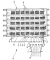
도 1은 본 발명에 따른 HRSG 및 가스 터빈 배기 확산기와 유체 연통으로 결합된 HRSG의 부분 절단면 입면도.
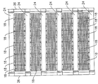
도 2는 본 발명에 따른 HRSG의 튜브들의 상류에 배치된 구조적 어레이 및 입구 덕트를 갖는 HRSG의 횡단면 입면도.
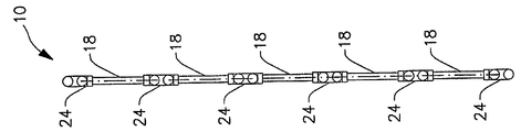
도 3a는 본 발명에 따른 HRSG에 부착된 구조적 어레이를 갖는 HRSG의 정면도.
도 3b는 도 3a의 구조적 어레이의 측면 입면도.
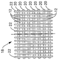
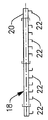
도 4a는 도 3a의 구조적 어레이의 쇠살대형 패널의 정면도.
도 4b는 도 4a의 쇠살대형 패널의 측면 입면도.
도 2는 본 발명에 따른 HRSG의 튜브들의 상류에 배치된 구조적 어레이 및 입구 덕트를 갖는 HRSG의 횡단면 입면도.
도 3a는 본 발명에 따른 HRSG에 부착된 구조적 어레이를 갖는 HRSG의 정면도.
도 3b는 도 3a의 구조적 어레이의 측면 입면도.
도 4a는 도 3a의 구조적 어레이의 쇠살대형 패널의 정면도.
도 4b는 도 4a의 쇠살대형 패널의 측면 입면도.
구조적 구성 요소의 어레이(10)가 가스 터빈(도시되지 않음)을 빠져나가는 고속 배기 스트림(14)을 확산시키고 또한 가스 유동을 HRSG(40) 내로 재분배하기 위해 튜브들(48)의 전방 행 앞에 위치되는, 유동 제어부에 대한 새로운 접근 방법이 제안되었다. 그와 같은 구성은 도 2 내지 도 4b에 도시되어 있다. 이들 도면들은 하나의 가능한 구조를 도시하고 있음에 주목한다. 다른 조합들도 이하에서 설명하고 있는 특징들이 디자인에 의해 충족되는 한 사용될 수 있다.
도 2는 본 발명에 따른 HRSG의 튜브들의 상류에 배치된 구조적 어레이 및 입구 덕트를 갖는 HRSG의 횡단면 입면도를 도시하고 있다. 도 2는 구조적 어레이(10)를 갖는 HRSG(40)을 설명한다.
도 3a는 본 발명에 따른 HRSG에 부착된 구조적 어레이를 갖는 HRSG의 정면도를 나타낸다.
도 3b는 도 3a의 구조적 어레이의 측면 입면도를 나타낸다.
도 2, 도 3a 및 도 3b의 경우, 구조적 어레이(10)는 HRSG(40)의 튜브 뱅크들(42)의 상류에 배치된다. 상기 구조적 어레이(10)는, 예를 들면 가스 터빈과 같은, 터빈(도시되지 않음)으로부터의 배기 스트림(14)의 유동을 제어하기 위해 상기 HRSG(40)의 상류 단부에서 지지부들(26) 또는 구조적 요소들에 장착 또는 부착된다. 도 3a에 도시된 바와 같이, 상기 구조적 어레이(10)는 상기 배기 스트림(14)을 결합 또는 제어하기 위한 충분한 영역 이상으로 상기 HRSG(40)의 상류 단부 너머로 연장한다.
도시된 실시예에 있어서, 상기 구조적 어레이(10)는 복수의 쇠살대형 패널들(18)을 포함한다.
도 4a는 도 3a의 구조적 어레이의 쇠살대형 패널의 정면도를 나타낸다.
도 4b는 도 4a의 쇠살대형 패널의 측면 입면도를 나타낸다.
다음에, 도 4a 및 도 4b를 참고로 하여 패널들(18)을 설명한다. 패널들(18)은 각각 복수의 수직 바들(22)에 연결되는 복수의 수평 바들(20)을 갖는다. 상기 바들(20, 22)은 고형의 중공형 또는 일반적으로는 U-자 형상을 가질 수 있다. 또한, 각각의 바의 횡단면은 어떠한 기하학적 형상(예를 들면, 라운드형, 타원형, 장방형, 필각형 등)이나 또는 U-자 형상을 가질 수 있다. 그리드 개구(12)는 균일하거나 비칙적으로 구성될 수 있다. 마찬가지로, 상기 어레이의 수직 및 수평 바들의 간격은 비균일하게 되거나 변동될 수 있다. 상기 패널(18)의 수직 바들(22)은 U-자 형상을 가지며, 여기서 U-자 형상의 바들은 상기 바들의 개구들이 상기 패널의 중앙을 향해 내부로 개방되도록 배향된다. 상기 U-자 형상의 수직 바들(22)이 그와 같은 배향으로 도시되었으나, 본 발명은 상기 U-자 형상의 바들이 어떠한 배향으로도 배치될 수 있는 것으로 고려하고 있다.
상기 패널들(18) 각각은 수평 지지부들(24)에 장착 또는 부착(예를 들면, 용접, 볼트 체결, 또는 다른 부착 수단)되며, 결국 상기 HRSG(40)의 구조적 지지부들(26)에 부착 또는 고정된다. 상기 패널들(18)을 상기 HRSG의 튜브들(46)이 아닌 상기 구조적 지지부들(26)에 장착함으로써 상기 튜브들 상의 피로가 감소된다. 도시된 실시예에 있어서, 상기 수평 지지부들(24)은 함께 용접된 한쌍의 수직 배치된 튜브들(30)로 구성된다. 그러나, 본 발명은 상기 수평 지지부들(24)이 어떠한 지지 빈으로 형성될 수도 있다는 사실을 고려한다.
도 2로 돌아가서, 유동 제어 구조적 어레이(10)를 갖는 상기 HRSG(40)과 가스 터빈(도시되지 않음)의 작동에 있어서, 상기 가스 터빈으로부터의 배기 스트림(14)은 연결 덕트(34)와 HRSG 입구 덕트(36)를 통해 흐른다. 고속 유동이 상기 쇠살대형 구조적 어레이(10)를 관통하며, 여기서 상기 배기 스트림(14)은 확산되고 또한 상기 HRSG(40)의 튜브들(46)을 가로질러 분배된다.
상기 구조적 어레이(10)는 고속 배기 스트림(14)에 의해 부여된 힘에 저항하기 위한 구조적 구성 요소들(20, 22, 24)로 구성된다. 핀고정 및/또는 슬립 연결부들은 열적 팽창을 위한 허용에 적합한 장소에 사용된다. 상기 구성 요소들(20, 22, 24)의 크기와 간격은, 상기 HRSG(40) 내로의 가스 유동의 분배를 개선시킴과 동시에, 가스 유동이 거의 없거나 또는 전혀 없는 전방 행 튜브들(48)의 섹션들에 대한 고속 배기 스트림(14)의 부분에 대한 방향을 변경시키기 위한 충분한 저항을 제공하도록 배열된다. 상기 구조적 구성 요소들(20, 22, 24)은 상기 어레이(10)를 통과하는 잔류 유동이 격자 개구들(12)을 통해 다량의 소형 제트들로 분배되도록 크기 및 간격이 결정된다. 상기 소형 제트들은 상기 격자 개구들(12)과 동일한 직경(D)으로 개시된다. 상기 구조적 어레이(10)로부터 상기 튜브들(46)까지의 거리의 약 1/10로 된다. 이는 상기 튜브들(46)에 도달하기 전에 소형 다중 제트들을 부분적으로 비산시키며, 상기 구조적 어레이(10) 범위를 넘어서는 허용되지 않는 속도의 영향 하에 놓일 수 있는 튜브들의 영역 상의 부하를 감소시킨다.
상기 구조적 어레이(10)에 의해 보호되는 튜브들(46)의 전방 행의 크기와 상기 격자 개구들(12)의 직경은 상기 특정 가스 터빈과 상기 HRSG(40)의 물리적 유동 모델링에 기초할 수 있다
다른 실시예들에 있어서, 구조적 어레이(10)는 상기 구조적 어레이와 튜브들(46)로부터의 거리가 조절될 수 있도록 조절 가능한 마운트들(도 2의 도면부호 50) 상에 위치한다. 그로 인해 배기 제트들이 상기 튜브들(46)과 충돌함에 따라 상기 배기 제트들의 다소의 비산을 조절할 수 있게 된다. 상기 배기 스트림(14)의 확산이 많으면 많을수록 배기 배압이 높아지는 결과가 초래되므로, 상기 시스템은 배압과 확산 모두를 위해 쌍방향으로 최적화될 수 있다.
본 발명은 다양한 예시적 실시예들과 관련하여 설명되었으나, 본 발명의 범위를 벗어나지 않는 한도 내에서 다양한 변경이 수행될 수 있으며 등가의 구성 요소들이 대체될 수 있음은 당업자들이라면 충분히 이해할 수 있을 것이다. 또한, 본 발명의 필수적인 범위를 벗어나지 않는 한도 내에서 특정 상황이나 재료들이 본 발명의 교시에 적용될 수 있도록 다양한 변경이 수행될 수 있다. 따라서, 본 발명은 본 발명을 수행하기 위해 의도된 최상의 모드로서 설명된 특정 실시예로 한정되지 아니하며, 첨부된 청구항들의 범위 내에 속하는 모든 실시예들을 포함하도록 의도된다.
Claims (15)
- 열 회수 시스템으로서,
터빈으로부터의 배기 스트림과 유체 연통하는 열 회수 증기 발생기(HRSG) 챔버와;
상기 HRSG 챔버에 배치된 복수의 튜브들; 및
상기 튜브들로부터 상류에 배치되는 쇠살대형(grate-like) 구조적 어레이로서, 상기 튜브들을 통과하기 전에 상기 배기 스트림을 확산시키는 상기 쇠살대형 구조적 어레이를 포함하는 열 회수 시스템. - 제 1 항에 있어서, 상기 쇠살대형 구조적 어레이는 직경을 갖는 격자 개구들을 가지며, 상기 구조적 어레이는 상기 격자 개구들의 직경이 상기 튜브들과 상기 구조적 어레이 사이의 거리의 약 1/10이 되도록 상기 튜브들로부터 떨어진 거리에 위치되는 열 회수 시스템.
- 제 1 항에 있어서, 상기 쇠살대형 구조적 어레이는 상기 튜브들로부터 떨어진 거리에 위치되며 또한 상기 거리가 조절되도록 허용하는 어태치먼트 구조를 채용하는 열 회수 시스템.
- 제 1 항에 있어서, 상기 쇠살대형 구조적 어레이는:
외부 쇠살대 구조; 및
상기 외부 쇠살대 구조 내에 체결되고 또한 그에 의해 고정되는 복수의 플레이트들을 추가로 포함하는 열 회수 시스템. - 제 4 항에 있어서, 상기 외부 쇠살대 구조는 개구 영역들을 떠나는 플레이트들로 완전히 채워지지 않는 열 회수 시스템.
- 제 4 항에 있어서, 상기 외부 쇠살대 구조는 배기 스트림이 미리 결정된 힘을 초과하는 장소들에서 플레이트들과 체결되는 열 회수 시스템.
- 제 1 항에 있어서, 상기 플레이트들은 함께 연결된 수평 바들 및 수직 바들로 이루어진 격자로 구성되는 열 회수 시스템.
- 제 7 항에 있어서, 상기 플레이트들은 가스 터빈 배기 스트림의 전형적인 온도에 대한 장기간의 노출에 대항하도록 적응된 재료로 구성되는 열 회수 시스템.
- 터빈 엔진의 배기 스트림으로부터 열을 효과적으로 회수하기 위한 방법으로서,
복수의 튜브들을 갖는 열 회수 증기 발생기(HRSG)를 제공하는 단계로서, 상기 HRSG는 상기 배기 스트림의 횡단면 크기보다 적어도 2배 이상 큰 횡단면 크기를 갖는, 상기 열 회수 증기 발생기(HRSG)를 제공하는 단계와;
상기 HRSG 전방의 미리 결정된 거리(D)에 쇠살대형(grate-like) 구조적 어레이를 위치시키는 단계; 및
상기 배기 스트림이 상기 구조적 어레이를 통해 상기 HRSG로 향하도록 상기 터빈 엔진을 위치시키는 단계로서, 상기 구조적 어레이는 상기 구조적 어레이가 배기 스트림으로부터 힘을 흡수하도록 하여, 상기 튜브들을 보호하고 또한 상기 배기 스트림의 횡단면보다 큰 상기 HRSG 내 튜브들의 부분을 커버하도록 상기 배기 스트림을 확산시키고, 상기 터빈 엔진을 위치시키는 단계를 포함하는 열 회수 방법. - 제 9 항에 있어서, 상기 어레이는 격자 개구들을 가지며, 상기 거리(D)에 대한 상기 쇠살대 직경의 비는 약 1/10인 열 회수 방법.
- 제 9 항에 있어서, 상기 쇠살대형 구조적 어레이를 제공하는 단계는:
외부 쇠살대 구조를 제공하는 단계; 및
상기 외부 쇠살대 구조 내에 체결되는 복수의 플레이트들을 체결하는 단계를 포함하는 열 회수 방법. - 제 11 항에 있어서, 상기 체결하는 단계는 외부 쇠살대 구조가 개구 영역들을 떠나는 플레이트들로 완전히 채워지지 않도록 플레이트들을 외부 쇠살대 구조 내에 체결하는 단계를 포함하는 열 회수 방법.
- 제 9 항에 있어서, 상기 쇠살대형 구조적 어레이를 위치시키는 단계는:
상기 HRSG 전방의 조절 가능한 거리(D)에 쇠살대형(grate-like) 구조적 어레이를 위치시키는 단계를 포함하며, 그 결과 상기 거리(D)는 상기 구조적 어레이에 의해 생성된 확산의 정도를 조절하도록 변경될 수 있는 열 회수 방법. - 제 9 항에 있어서, 상기 쇠살대형 구조적 어레이를 위치시키는 단계는:
가스 터빈 배기 스트림의 전형적인 온도에 대한 장기간의 노출에 대항하도록 적응된 재료로 구성되는 플레이트들을 갖는 쇠살대형 구조적 어레이를 위치시키는 단계를 포함하는 열 회수 방법. - 제 11 항에 있어서, 상기 체결하는 단계는:
플레이트들을 함께 연결된 수평 바들 및 수직 바들로 이루어진 격자로 구성되는 외부 쇠살대 구조 내에 체결시키는 단계를 포함하는 열 회수 방법.
Applications Claiming Priority (5)
| Application Number | Priority Date | Filing Date | Title |
|---|---|---|---|
| US23960409P | 2009-09-03 | 2009-09-03 | |
| US61/239,604 | 2009-09-03 | ||
| US12/850,108 | 2010-08-04 | ||
| US12/850,108 US10001272B2 (en) | 2009-09-03 | 2010-08-04 | Apparatus and method for close coupling of heat recovery steam generators with gas turbines |
| PCT/US2010/044496 WO2011028356A2 (en) | 2009-09-03 | 2010-08-05 | Apparatus and method for close coupling of heat recovery steam generators with gas turbines |
Related Child Applications (1)
| Application Number | Title | Priority Date | Filing Date |
|---|---|---|---|
| KR1020157019607A Division KR20150091180A (ko) | 2009-09-03 | 2010-08-05 | 가스 터빈들을 구비한 열 회수 증기 발생기의 밀착 결합을 위한 장치 |
Publications (1)
| Publication Number | Publication Date |
|---|---|
| KR20120058598A true KR20120058598A (ko) | 2012-06-07 |
Family
ID=43622825
Family Applications (3)
| Application Number | Title | Priority Date | Filing Date |
|---|---|---|---|
| KR1020157019607A KR20150091180A (ko) | 2009-09-03 | 2010-08-05 | 가스 터빈들을 구비한 열 회수 증기 발생기의 밀착 결합을 위한 장치 |
| KR1020167030883A KR101850236B1 (ko) | 2009-09-03 | 2010-08-05 | 가스 터빈들을 구비한 열 회수 증기 발생기의 밀착 결합을 위한 장치 |
| KR1020127008258A KR20120058598A (ko) | 2009-09-03 | 2010-08-05 | 가스 터빈들을 구비한 열 회수 증기 발생기의 밀착 결합을 위한 장치 및 방법 |
Family Applications Before (2)
| Application Number | Title | Priority Date | Filing Date |
|---|---|---|---|
| KR1020157019607A KR20150091180A (ko) | 2009-09-03 | 2010-08-05 | 가스 터빈들을 구비한 열 회수 증기 발생기의 밀착 결합을 위한 장치 |
| KR1020167030883A KR101850236B1 (ko) | 2009-09-03 | 2010-08-05 | 가스 터빈들을 구비한 열 회수 증기 발생기의 밀착 결합을 위한 장치 |
Country Status (10)
| Country | Link |
|---|---|
| US (1) | US10001272B2 (ko) |
| EP (1) | EP2473781B1 (ko) |
| KR (3) | KR20150091180A (ko) |
| CN (1) | CN102498343B (ko) |
| CA (1) | CA2773092C (ko) |
| IL (1) | IL218389A (ko) |
| IN (1) | IN2012DN02834A (ko) |
| MX (1) | MX2012002554A (ko) |
| RU (1) | RU2620309C2 (ko) |
| WO (1) | WO2011028356A2 (ko) |
Families Citing this family (73)
| Publication number | Priority date | Publication date | Assignee | Title |
|---|---|---|---|---|
| WO2009121008A2 (en) | 2008-03-28 | 2009-10-01 | Exxonmobil Upstream Research Company | Low emission power generation and hydrocarbon recovery systems and methods |
| CA2715186C (en) | 2008-03-28 | 2016-09-06 | Exxonmobil Upstream Research Company | Low emission power generation and hydrocarbon recovery systems and methods |
| CN102177326B (zh) | 2008-10-14 | 2014-05-07 | 埃克森美孚上游研究公司 | 控制燃烧产物的方法与装置 |
| CN102459850B (zh) | 2009-06-05 | 2015-05-20 | 埃克森美孚上游研究公司 | 燃烧器系统和使用燃烧器系统的方法 |
| EA023673B1 (ru) | 2009-11-12 | 2016-06-30 | Эксонмобил Апстрим Рисерч Компани | Система и способ для низкоэмиссионного производства электроэнергии и извлечения углеводородов |
| EP2325559B1 (de) * | 2009-11-19 | 2016-12-28 | NEM Power-Systems, Niederlassung Deutschland der NEM B.V. Niederlande | Anordnung zur Beeinflussung einer Abgasströmung |
| MY160833A (en) | 2010-07-02 | 2017-03-31 | Exxonmobil Upstream Res Co | Stoichiometric combustion of enriched air with exhaust gas recirculation |
| AU2011271633B2 (en) | 2010-07-02 | 2015-06-11 | Exxonmobil Upstream Research Company | Low emission triple-cycle power generation systems and methods |
| TWI593878B (zh) | 2010-07-02 | 2017-08-01 | 艾克頌美孚上游研究公司 | 用於控制燃料燃燒之系統及方法 |
| CA2801499C (en) | 2010-07-02 | 2017-01-03 | Exxonmobil Upstream Research Company | Low emission power generation systems and methods |
| MX341981B (es) | 2010-07-02 | 2016-09-08 | Exxonmobil Upstream Res Company * | Combustion estequiometrica con recirculacion de gas de escape y enfriador de contacto directo. |
| CN105736150B (zh) | 2010-08-06 | 2018-03-06 | 埃克森美孚上游研究公司 | 优化化学计量燃烧的系统和方法 |
| US9399950B2 (en) | 2010-08-06 | 2016-07-26 | Exxonmobil Upstream Research Company | Systems and methods for exhaust gas extraction |
| TWI563166B (en) | 2011-03-22 | 2016-12-21 | Exxonmobil Upstream Res Co | Integrated generation systems and methods for generating power |
| TWI564474B (zh) | 2011-03-22 | 2017-01-01 | 艾克頌美孚上游研究公司 | 於渦輪系統中控制化學計量燃燒的整合系統和使用彼之產生動力的方法 |
| TWI593872B (zh) | 2011-03-22 | 2017-08-01 | 艾克頌美孚上游研究公司 | 整合系統及產生動力之方法 |
| TWI563165B (en) | 2011-03-22 | 2016-12-21 | Exxonmobil Upstream Res Co | Power generation system and method for generating power |
| CN104428490B (zh) | 2011-12-20 | 2018-06-05 | 埃克森美孚上游研究公司 | 提高的煤层甲烷生产 |
| US9353682B2 (en) | 2012-04-12 | 2016-05-31 | General Electric Company | Methods, systems and apparatus relating to combustion turbine power plants with exhaust gas recirculation |
| US10273880B2 (en) | 2012-04-26 | 2019-04-30 | General Electric Company | System and method of recirculating exhaust gas for use in a plurality of flow paths in a gas turbine engine |
| US9784185B2 (en) | 2012-04-26 | 2017-10-10 | General Electric Company | System and method for cooling a gas turbine with an exhaust gas provided by the gas turbine |
| US9599070B2 (en) | 2012-11-02 | 2017-03-21 | General Electric Company | System and method for oxidant compression in a stoichiometric exhaust gas recirculation gas turbine system |
| US10161312B2 (en) | 2012-11-02 | 2018-12-25 | General Electric Company | System and method for diffusion combustion with fuel-diluent mixing in a stoichiometric exhaust gas recirculation gas turbine system |
| US10107495B2 (en) | 2012-11-02 | 2018-10-23 | General Electric Company | Gas turbine combustor control system for stoichiometric combustion in the presence of a diluent |
| US9631815B2 (en) | 2012-12-28 | 2017-04-25 | General Electric Company | System and method for a turbine combustor |
| US10215412B2 (en) | 2012-11-02 | 2019-02-26 | General Electric Company | System and method for load control with diffusion combustion in a stoichiometric exhaust gas recirculation gas turbine system |
| US9803865B2 (en) | 2012-12-28 | 2017-10-31 | General Electric Company | System and method for a turbine combustor |
| US9574496B2 (en) | 2012-12-28 | 2017-02-21 | General Electric Company | System and method for a turbine combustor |
| US9611756B2 (en) | 2012-11-02 | 2017-04-04 | General Electric Company | System and method for protecting components in a gas turbine engine with exhaust gas recirculation |
| US9869279B2 (en) | 2012-11-02 | 2018-01-16 | General Electric Company | System and method for a multi-wall turbine combustor |
| US9708977B2 (en) | 2012-12-28 | 2017-07-18 | General Electric Company | System and method for reheat in gas turbine with exhaust gas recirculation |
| US10208677B2 (en) | 2012-12-31 | 2019-02-19 | General Electric Company | Gas turbine load control system |
| US9581081B2 (en) | 2013-01-13 | 2017-02-28 | General Electric Company | System and method for protecting components in a gas turbine engine with exhaust gas recirculation |
| US9512759B2 (en) | 2013-02-06 | 2016-12-06 | General Electric Company | System and method for catalyst heat utilization for gas turbine with exhaust gas recirculation |
| TW201502356A (zh) | 2013-02-21 | 2015-01-16 | Exxonmobil Upstream Res Co | 氣渦輪機排氣中氧之減少 |
| US9938861B2 (en) | 2013-02-21 | 2018-04-10 | Exxonmobil Upstream Research Company | Fuel combusting method |
| WO2014133406A1 (en) | 2013-02-28 | 2014-09-04 | General Electric Company | System and method for a turbine combustor |
| TW201500635A (zh) | 2013-03-08 | 2015-01-01 | Exxonmobil Upstream Res Co | 處理廢氣以供用於提高油回收 |
| US9618261B2 (en) | 2013-03-08 | 2017-04-11 | Exxonmobil Upstream Research Company | Power generation and LNG production |
| AU2014226413B2 (en) | 2013-03-08 | 2016-04-28 | Exxonmobil Upstream Research Company | Power generation and methane recovery from methane hydrates |
| US20140250945A1 (en) | 2013-03-08 | 2014-09-11 | Richard A. Huntington | Carbon Dioxide Recovery |
| JP6484845B2 (ja) * | 2013-06-25 | 2019-03-20 | 三菱重工コンプレッサ株式会社 | ガスタービンコンバインドサイクル設備、水上設備 |
| US9631542B2 (en) | 2013-06-28 | 2017-04-25 | General Electric Company | System and method for exhausting combustion gases from gas turbine engines |
| US9617914B2 (en) | 2013-06-28 | 2017-04-11 | General Electric Company | Systems and methods for monitoring gas turbine systems having exhaust gas recirculation |
| TWI654368B (zh) | 2013-06-28 | 2019-03-21 | 美商艾克頌美孚上游研究公司 | 用於控制在廢氣再循環氣渦輪機系統中的廢氣流之系統、方法與媒體 |
| US9835089B2 (en) | 2013-06-28 | 2017-12-05 | General Electric Company | System and method for a fuel nozzle |
| US9903588B2 (en) | 2013-07-30 | 2018-02-27 | General Electric Company | System and method for barrier in passage of combustor of gas turbine engine with exhaust gas recirculation |
| US9587510B2 (en) | 2013-07-30 | 2017-03-07 | General Electric Company | System and method for a gas turbine engine sensor |
| US9951658B2 (en) | 2013-07-31 | 2018-04-24 | General Electric Company | System and method for an oxidant heating system |
| US10145626B2 (en) | 2013-11-15 | 2018-12-04 | General Electric Technology Gmbh | Internally stiffened extended service heat recovery steam generator apparatus |
| US9752458B2 (en) | 2013-12-04 | 2017-09-05 | General Electric Company | System and method for a gas turbine engine |
| US10030588B2 (en) | 2013-12-04 | 2018-07-24 | General Electric Company | Gas turbine combustor diagnostic system and method |
| US10227920B2 (en) | 2014-01-15 | 2019-03-12 | General Electric Company | Gas turbine oxidant separation system |
| US9863267B2 (en) | 2014-01-21 | 2018-01-09 | General Electric Company | System and method of control for a gas turbine engine |
| US9915200B2 (en) | 2014-01-21 | 2018-03-13 | General Electric Company | System and method for controlling the combustion process in a gas turbine operating with exhaust gas recirculation |
| US10079564B2 (en) | 2014-01-27 | 2018-09-18 | General Electric Company | System and method for a stoichiometric exhaust gas recirculation gas turbine system |
| US10047633B2 (en) | 2014-05-16 | 2018-08-14 | General Electric Company | Bearing housing |
| US10060359B2 (en) | 2014-06-30 | 2018-08-28 | General Electric Company | Method and system for combustion control for gas turbine system with exhaust gas recirculation |
| US10655542B2 (en) | 2014-06-30 | 2020-05-19 | General Electric Company | Method and system for startup of gas turbine system drive trains with exhaust gas recirculation |
| US9885290B2 (en) | 2014-06-30 | 2018-02-06 | General Electric Company | Erosion suppression system and method in an exhaust gas recirculation gas turbine system |
| US9819292B2 (en) | 2014-12-31 | 2017-11-14 | General Electric Company | Systems and methods to respond to grid overfrequency events for a stoichiometric exhaust recirculation gas turbine |
| US9869247B2 (en) | 2014-12-31 | 2018-01-16 | General Electric Company | Systems and methods of estimating a combustion equivalence ratio in a gas turbine with exhaust gas recirculation |
| US10788212B2 (en) | 2015-01-12 | 2020-09-29 | General Electric Company | System and method for an oxidant passageway in a gas turbine system with exhaust gas recirculation |
| US10094566B2 (en) | 2015-02-04 | 2018-10-09 | General Electric Company | Systems and methods for high volumetric oxidant flow in gas turbine engine with exhaust gas recirculation |
| US10316746B2 (en) | 2015-02-04 | 2019-06-11 | General Electric Company | Turbine system with exhaust gas recirculation, separation and extraction |
| US10253690B2 (en) | 2015-02-04 | 2019-04-09 | General Electric Company | Turbine system with exhaust gas recirculation, separation and extraction |
| US10267270B2 (en) | 2015-02-06 | 2019-04-23 | General Electric Company | Systems and methods for carbon black production with a gas turbine engine having exhaust gas recirculation |
| US10145269B2 (en) | 2015-03-04 | 2018-12-04 | General Electric Company | System and method for cooling discharge flow |
| US10480792B2 (en) | 2015-03-06 | 2019-11-19 | General Electric Company | Fuel staging in a gas turbine engine |
| EP3457071B1 (en) * | 2017-09-18 | 2023-05-17 | Valeo Autosystemy SP. Z.O.O. | A protection device for a heat exchanger |
| US11209157B2 (en) | 2018-07-27 | 2021-12-28 | The Clever-Brooks Company, Inc. | Modular heat recovery steam generator system for rapid installation |
| US10907821B2 (en) * | 2019-03-07 | 2021-02-02 | General Electric Company | HRSG with stepped tube restraints |
| US11519597B2 (en) * | 2019-11-08 | 2022-12-06 | General Electric Company | Multiple cooled supports for heat exchange tubes in heat exchanger |
Family Cites Families (21)
| Publication number | Priority date | Publication date | Assignee | Title |
|---|---|---|---|---|
| US2968147A (en) * | 1957-04-23 | 1961-01-17 | Boeing Co | Supersonic diffuser with shock positioning means |
| US3442324A (en) * | 1967-03-06 | 1969-05-06 | American Mach & Foundry | Heat recovery device for turbine gases |
| DE3206626A1 (de) * | 1982-02-24 | 1983-09-01 | Kraftwerk Union AG, 4330 Mülheim | Abgaskanal fuer gasturbinen |
| US4427058A (en) * | 1982-12-13 | 1984-01-24 | General Electric Company | HRSG Sidewall baffle |
| RU2018047C1 (ru) | 1989-09-05 | 1994-08-15 | Акционерное общество "Белгородский завод энергетического машиностроения" | Котел-утилизатор |
| US5431009A (en) * | 1993-12-21 | 1995-07-11 | Combustion Engineering, Inc. | Heat recovery steam generator inlet duct |
| US5532439A (en) * | 1994-06-23 | 1996-07-02 | Transco Products Inc. | Silencer assembly with acoustical modules therein |
| JP3512487B2 (ja) | 1994-10-24 | 2004-03-29 | 株式会社東芝 | 排熱回収ボイラ |
| US5555718A (en) * | 1994-11-10 | 1996-09-17 | Combustion Engineering, Inc. | Method and apparatus for injecting reactant for catalytic reduction in a gas turbine combined cycle system |
| IT1290579B1 (it) | 1997-03-07 | 1998-12-10 | Abb Combustion Engineering S P | Caldaia a recupero, munita di condotto divergente. |
| DE19737507A1 (de) * | 1997-08-28 | 1999-03-11 | Dampers Engineering Gmbh | Anordnung zur Beeinflussung des Dralls eines Abgasstroms |
| US5946901A (en) * | 1997-12-17 | 1999-09-07 | Combustion Engineering, Inc. | Method and apparatus for improving gas flow in heat recovery steam generators |
| DE19959342A1 (de) * | 1999-12-09 | 2001-06-13 | Abb Alstom Power Ch Ag | Abhitzedampferzeuger |
| DE10017987C1 (de) * | 2000-04-11 | 2001-11-22 | Nem Power Systems Niederlassun | Verfahren und Anordnung zur Beaufschlagung eines Abhitzekessels mit dem Abgas einer Gasturbine |
| US6453852B1 (en) * | 2000-05-22 | 2002-09-24 | Corn Company, Inc. | Temperature stratified superheater and duct burner |
| US20030115817A1 (en) * | 2000-06-22 | 2003-06-26 | New Horizons Shutters, Inc. | Reinforced window shutter |
| US6851514B2 (en) * | 2002-04-15 | 2005-02-08 | Air Handling Engineering Ltd. | Outlet silencer and heat recovery structures for gas turbine |
| EP1650497B1 (en) * | 2003-07-30 | 2013-09-11 | Babcock-Hitachi Kabushiki Kaisha | Heat exchanger tube panel module, and method of constructing exhaust heat recovery boiler using the module |
| US7963097B2 (en) * | 2008-01-07 | 2011-06-21 | Alstom Technology Ltd | Flexible assembly of recuperator for combustion turbine exhaust |
| US20100064655A1 (en) * | 2008-09-16 | 2010-03-18 | General Electric Company | System and method for managing turbine exhaust gas temperature |
| EP2325559B1 (de) * | 2009-11-19 | 2016-12-28 | NEM Power-Systems, Niederlassung Deutschland der NEM B.V. Niederlande | Anordnung zur Beeinflussung einer Abgasströmung |
-
2010
- 2010-08-04 US US12/850,108 patent/US10001272B2/en active Active
- 2010-08-05 KR KR1020157019607A patent/KR20150091180A/ko active Application Filing
- 2010-08-05 IN IN2834DEN2012 patent/IN2012DN02834A/en unknown
- 2010-08-05 KR KR1020167030883A patent/KR101850236B1/ko active IP Right Grant
- 2010-08-05 CN CN201080040389.2A patent/CN102498343B/zh not_active Expired - Fee Related
- 2010-08-05 MX MX2012002554A patent/MX2012002554A/es active IP Right Grant
- 2010-08-05 RU RU2012112807A patent/RU2620309C2/ru not_active IP Right Cessation
- 2010-08-05 WO PCT/US2010/044496 patent/WO2011028356A2/en active Application Filing
- 2010-08-05 CA CA2773092A patent/CA2773092C/en not_active Expired - Fee Related
- 2010-08-05 EP EP10745054.6A patent/EP2473781B1/en active Active
- 2010-08-05 KR KR1020127008258A patent/KR20120058598A/ko not_active Application Discontinuation
-
2012
- 2012-02-29 IL IL218389A patent/IL218389A/en not_active IP Right Cessation
Also Published As
| Publication number | Publication date |
|---|---|
| IN2012DN02834A (ko) | 2015-07-24 |
| KR20160130534A (ko) | 2016-11-11 |
| RU2012112807A (ru) | 2013-10-10 |
| WO2011028356A3 (en) | 2011-07-21 |
| CN102498343A (zh) | 2012-06-13 |
| AU2010289954B2 (en) | 2016-02-11 |
| US20110048010A1 (en) | 2011-03-03 |
| AU2010289954A1 (en) | 2012-03-29 |
| US10001272B2 (en) | 2018-06-19 |
| IL218389A0 (en) | 2012-04-30 |
| RU2620309C2 (ru) | 2017-05-24 |
| WO2011028356A2 (en) | 2011-03-10 |
| CA2773092C (en) | 2017-07-25 |
| MX2012002554A (es) | 2012-06-01 |
| KR20150091180A (ko) | 2015-08-07 |
| EP2473781A2 (en) | 2012-07-11 |
| CN102498343B (zh) | 2018-10-26 |
| AU2010289954A8 (en) | 2016-02-25 |
| CA2773092A1 (en) | 2011-03-10 |
| EP2473781B1 (en) | 2021-05-26 |
| IL218389A (en) | 2017-05-29 |
| KR101850236B1 (ko) | 2018-04-18 |
Similar Documents
| Publication | Publication Date | Title |
|---|---|---|
| KR20120058598A (ko) | 가스 터빈들을 구비한 열 회수 증기 발생기의 밀착 결합을 위한 장치 및 방법 | |
| US20050120699A1 (en) | Heat recovery apparatus with aerodynamic diffusers | |
| AU2003252325B2 (en) | Heat exchanger tube panel module, and method of constructing exhaust heat recovery boiler using the module | |
| JP4812706B2 (ja) | ガスタービン吸気装置 | |
| CN106051724B (zh) | 用于热回收蒸汽发生器的套环支承式压力部件 | |
| KR101777431B1 (ko) | 배기 가스 유동에 영향을 주기 위한 어셈블리 | |
| US6050084A (en) | Sound absorbing flue-gas duct for a gas and steam turbine plant | |
| AU2010289954B9 (en) | Apparatus and method for close coupling of heat recovery steam generators with gas turbines | |
| CN106246250B (zh) | 用于核电厂的蒸汽倾卸装置 | |
| KR101691866B1 (ko) | 태양열 굴뚝발전소의 터빈부 윈드터널에 대한 장치 | |
| AU2010289954B8 (en) | Apparatus and method for close coupling of heat recovery steam generators with gas turbines | |
| US8596227B2 (en) | Steam generator | |
| JP3515979B2 (ja) | ガスタービン用サイレンサ | |
| CN212205737U (zh) | 一种工业生产废气余热回收利用设备 | |
| JP2004077096A (ja) | 助燃バーナ付き排熱回収ボイラ | |
| JP6514490B2 (ja) | 内部で補強された高寿命な排熱回収ボイラ装置 | |
| JPH07167571A (ja) | 発電プラントの復水器 | |
| TH73519B (th) | เครื่องมือและวิธีการสำหรับการต่อประกบปิดของเครื่องกำเนิดไอน้ำแบบนำความร้อนกลับมาใช้ซึ่งมีกังหันแก๊ส | |
| TH166503A (th) | เครื่องมือและวิธีการสำหรับการต่อประกบปิดของเครื่องกำเนิดไอน้ำแบบนำความร้อนกลับมาใช้ซึ่งมีกังหันแก๊ส | |
| US7144560B2 (en) | Frame structure for high-temperature denitration apparatus | |
| RU2229655C2 (ru) | Петлевая ширмовая поверхность нагрева | |
| JP2023114708A (ja) | ケーシング構造物およびケーシング構造物の組立方法 | |
| JP2006170495A (ja) | 燃焼装置 | |
| JPH06272847A (ja) | ガスダクト装置 | |
| JPH04203792A (ja) | 蒸気ダンパ |
Legal Events
| Date | Code | Title | Description |
|---|---|---|---|
| A201 | Request for examination | ||
| AMND | Amendment | ||
| E902 | Notification of reason for refusal | ||
| AMND | Amendment | ||
| E902 | Notification of reason for refusal | ||
| AMND | Amendment | ||
| E601 | Decision to refuse application | ||
| AMND | Amendment | ||
| E801 | Decision on dismissal of amendment | ||
| A107 | Divisional application of patent | ||
| WITB | Written withdrawal of application |