US9512759B2 - System and method for catalyst heat utilization for gas turbine with exhaust gas recirculation - Google Patents
System and method for catalyst heat utilization for gas turbine with exhaust gas recirculation Download PDFInfo
- Publication number
- US9512759B2 US9512759B2 US14/173,683 US201414173683A US9512759B2 US 9512759 B2 US9512759 B2 US 9512759B2 US 201414173683 A US201414173683 A US 201414173683A US 9512759 B2 US9512759 B2 US 9512759B2
- Authority
- US
- United States
- Prior art keywords
- exhaust gas
- turbine
- catalytic converter
- combustion
- fuel
- Prior art date
- Legal status (The legal status is an assumption and is not a legal conclusion. Google has not performed a legal analysis and makes no representation as to the accuracy of the status listed.)
- Expired - Fee Related, expires
Links
Images


Classifications
-
- F—MECHANICAL ENGINEERING; LIGHTING; HEATING; WEAPONS; BLASTING
- F01—MACHINES OR ENGINES IN GENERAL; ENGINE PLANTS IN GENERAL; STEAM ENGINES
- F01N—GAS-FLOW SILENCERS OR EXHAUST APPARATUS FOR MACHINES OR ENGINES IN GENERAL; GAS-FLOW SILENCERS OR EXHAUST APPARATUS FOR INTERNAL-COMBUSTION ENGINES
- F01N3/00—Exhaust or silencing apparatus having means for purifying, rendering innocuous, or otherwise treating exhaust
- F01N3/08—Exhaust or silencing apparatus having means for purifying, rendering innocuous, or otherwise treating exhaust for rendering innocuous
- F01N3/10—Exhaust or silencing apparatus having means for purifying, rendering innocuous, or otherwise treating exhaust for rendering innocuous by thermal or catalytic conversion of noxious components of exhaust
-
- E—FIXED CONSTRUCTIONS
- E21—EARTH OR ROCK DRILLING; MINING
- E21B—EARTH OR ROCK DRILLING; OBTAINING OIL, GAS, WATER, SOLUBLE OR MELTABLE MATERIALS OR A SLURRY OF MINERALS FROM WELLS
- E21B43/00—Methods or apparatus for obtaining oil, gas, water, soluble or meltable materials or a slurry of minerals from wells
- E21B43/16—Enhanced recovery methods for obtaining hydrocarbons
- E21B43/166—Injecting a gaseous medium; Injecting a gaseous medium and a liquid medium
-
- F—MECHANICAL ENGINEERING; LIGHTING; HEATING; WEAPONS; BLASTING
- F02—COMBUSTION ENGINES; HOT-GAS OR COMBUSTION-PRODUCT ENGINE PLANTS
- F02C—GAS-TURBINE PLANTS; AIR INTAKES FOR JET-PROPULSION PLANTS; CONTROLLING FUEL SUPPLY IN AIR-BREATHING JET-PROPULSION PLANTS
- F02C3/00—Gas-turbine plants characterised by the use of combustion products as the working fluid
- F02C3/34—Gas-turbine plants characterised by the use of combustion products as the working fluid with recycling of part of the working fluid, i.e. semi-closed cycles with combustion products in the closed part of the cycle
-
- E—FIXED CONSTRUCTIONS
- E21—EARTH OR ROCK DRILLING; MINING
- E21B—EARTH OR ROCK DRILLING; OBTAINING OIL, GAS, WATER, SOLUBLE OR MELTABLE MATERIALS OR A SLURRY OF MINERALS FROM WELLS
- E21B43/00—Methods or apparatus for obtaining oil, gas, water, soluble or meltable materials or a slurry of minerals from wells
- E21B43/16—Enhanced recovery methods for obtaining hydrocarbons
-
- F—MECHANICAL ENGINEERING; LIGHTING; HEATING; WEAPONS; BLASTING
- F05—INDEXING SCHEMES RELATING TO ENGINES OR PUMPS IN VARIOUS SUBCLASSES OF CLASSES F01-F04
- F05D—INDEXING SCHEME FOR ASPECTS RELATING TO NON-POSITIVE-DISPLACEMENT MACHINES OR ENGINES, GAS-TURBINES OR JET-PROPULSION PLANTS
- F05D2270/00—Control
- F05D2270/01—Purpose of the control system
- F05D2270/08—Purpose of the control system to produce clean exhaust gases
-
- Y—GENERAL TAGGING OF NEW TECHNOLOGICAL DEVELOPMENTS; GENERAL TAGGING OF CROSS-SECTIONAL TECHNOLOGIES SPANNING OVER SEVERAL SECTIONS OF THE IPC; TECHNICAL SUBJECTS COVERED BY FORMER USPC CROSS-REFERENCE ART COLLECTIONS [XRACs] AND DIGESTS
- Y02—TECHNOLOGIES OR APPLICATIONS FOR MITIGATION OR ADAPTATION AGAINST CLIMATE CHANGE
- Y02E—REDUCTION OF GREENHOUSE GAS [GHG] EMISSIONS, RELATED TO ENERGY GENERATION, TRANSMISSION OR DISTRIBUTION
- Y02E20/00—Combustion technologies with mitigation potential
- Y02E20/16—Combined cycle power plant [CCPP], or combined cycle gas turbine [CCGT]
Definitions
- the subject matter disclosed herein relates to gas turbines, and more specifically, to gas turbines with exhaust gas recirculation.
- a gas turbine engine combusts a mixture of fuel and oxidant to generate hot exhaust gases, which in turn drive one or more turbine stages.
- the hot exhaust gases force turbine blades to rotate, thereby driving a shaft to rotate one or more loads.
- the exhaust gas is generally at an elevated temperature, and thus represents a source of waste heat not used by the gas turbine engine.
- the waste heat represents a loss of energy or efficiency of the gas turbine engine.
- the waste heat may be used in other systems, such as a heat recovery steam generator (HRSG), this use of the waste heat does not increase the energy recovery or efficiency of the gas turbine engine itself.
- HRSG heat recovery steam generator
- a system in a first embodiment, includes a turbine combustor, a turbine, an exhaust gas compressor, a flow path, and at least one catalytic converter.
- the turbine is driven by combustion products from the turbine combustor.
- the exhaust compressor is configured to compress and route an exhaust gas from the turbine to the turbine combustor.
- the flow path leads from the exhaust gas compressor, through turbine combustor, and into the turbine.
- the catalytic converter is disposed along the flow path.
- a system in a second embodiment, includes a turbine combustion section configured to mount between an exhaust gas compressor and a turbine.
- the turbine combustion section includes at least one catalytic converter disposed along a flow path from the exhaust gas compressor into the turbine, through the turbine combustion section.
- a method in a third embodiment, includes driving a turbine with combustion products from a turbine combustor and compressing an exhaust gas from the turbine in an exhaust gas compressor. The method also includes routing the exhaust gas along a flow path from the exhaust gas compressor, through the turbine combustor, and into the turbine. The method also includes catalytically converting a fluid flow along the flow path with at least one catalytic converter. The fluid flow includes the exhaust gas.
- FIG. 1 is a diagram of an embodiment of a system having a turbine-based service system coupled to a hydrocarbon production system;
- FIG. 2 is a diagram of an embodiment of the system of FIG. 1 , further illustrating a control system and a combined cycle system;
- FIG. 3 is a diagram of an embodiment of the system of FIGS. 1 and 2 , further illustrating details of a gas turbine engine, exhaust gas supply system, and exhaust gas processing system;
- FIG. 4 is a flow chart of an embodiment of a process for operating the system of FIGS. 1-3 ;
- FIG. 5 illustrates an embodiment of a method for catalytically converting exhaust gas recirculated along a catalytic flow path between a compressor section and a turbine section of a gas turbine engine
- FIG. 6 illustrates a block diagram of an embodiment of a gas turbine system with exhaust gas recirculation (EGR), illustrating with one or more catalytic converters along a catalytic flow path between a compressor section and a turbine section;
- EGR exhaust gas recirculation
- FIG. 7 is a schematic of an embodiment of a catalytic converter along a catalytic flow path
- FIG. 8 is a schematic of an embodiment of a gas turbine system, illustrating a compressor section and combustor section with one or more catalytic converters;
- FIG. 9 is a block diagram of an embodiment of a gas turbine system, illustrating a system for catalytic partial oxidation combustion of an EGR flow between a compressor section and a turbine section;
- FIG. 10 is block diagram of an embodiment of a turbine-based service system with catalytic converters arranged along a catalytic flow path between a compressor section and a turbine section.
- the disclosed embodiments relate generally to gas turbine systems with exhaust gas recirculation (EGR), and particularly stoichiometric operation of the gas turbine systems using EGR.
- the gas turbine systems may be configured to recirculate the exhaust gas along an exhaust recirculation path, stoichiometrically combust fuel and oxidant along with at least some of the recirculated exhaust gas, and capture the exhaust gas for use in various target systems.
- the recirculation of the exhaust gas along with stoichiometric combustion may help to increase the concentration level of carbon dioxide (CO 2 ) in the exhaust gas, which can then be post treated to separate and purify the CO 2 and nitrogen (N 2 ) for use in various target systems.
- CO 2 carbon dioxide
- N 2 nitrogen
- the gas turbine systems also may employ various exhaust gas processing (e.g., heat recovery, catalyst reactions, etc.) along the exhaust recirculation path, thereby increasing the concentration level of CO 2 , reducing concentration levels of other emissions (e.g., carbon monoxide, nitrogen oxides, and unburnt hydrocarbons), and increasing energy recovery (e.g., with heat recovery units).
- the gas turbine engines may be configured to combust the fuel and oxidant with one or more diffusion flames (e.g., using diffusion fuel nozzles), premix flames (e.g., using premix fuel nozzles), or any combination thereof.
- the diffusion flames may help to maintain stability and operation within certain limits for stoichiometric combustion, which in turn helps to increase production of CO 2 .
- a gas turbine system operating with diffusion flames may enable a greater quantity of EGR, as compared to a gas turbine system operating with premix flames.
- the increased quantity of EGR helps to increase CO 2 production.
- Possible target systems include pipelines, storage tanks, carbon sequestration systems, and hydrocarbon production systems, such as enhanced oil recovery (EOR) systems.
- FIG. 1 is a diagram of an embodiment of a system 10 having a hydrocarbon production system 12 associated with a turbine-based service system 14 .
- various embodiments of the turbine-based service system 14 are configured to provide various services, such as electrical power, mechanical power, and fluids (e.g., exhaust gas), to the hydrocarbon production system 12 to facilitate the production or retrieval of oil and/or gas.
- the hydrocarbon production system 12 includes an oil/gas extraction system 16 and an enhanced oil recovery (EOR) system 18 , which are coupled to a subterranean reservoir 20 (e.g., an oil, gas, or hydrocarbon reservoir).
- EOR enhanced oil recovery
- the oil/gas extraction system 16 includes a variety of surface equipment 22 , such as a Christmas tree or production tree 24 , coupled to an oil/gas well 26 .
- the well 26 may include one or more tubulars 28 extending through a drilled bore 30 in the earth 32 to the subterranean reservoir 20 .
- the tree 24 includes one or more valves, chokes, isolation sleeves, blowout preventers, and various flow control devices, which regulate pressures and control flows to and from the subterranean reservoir 20 .
- the EOR system 18 may increase the production of oil or gas by injecting one or more fluids into the subterranean reservoir 20 .
- the EOR system 18 may include a fluid injection system 34 , which has one or more tubulars 36 extending through a bore 38 in the earth 32 to the subterranean reservoir 20 .
- the EOR system 18 may route one or more fluids 40 , such as gas, steam, water, chemicals, or any combination thereof, into the fluid injection system 34 .
- the EOR system 18 may be coupled to the turbine-based service system 14 , such that the system 14 routes an exhaust gas 42 (e.g., substantially or entirely free of oxygen) to the EOR system 18 for use as the injection fluid 40 .
- an exhaust gas 42 e.g., substantially or entirely free of oxygen
- the fluid injection system 34 routes the fluid 40 (e.g., the exhaust gas 42 ) through the one or more tubulars 36 into the subterranean reservoir 20 , as indicated by arrows 44 .
- the injection fluid 40 enters the subterranean reservoir 20 through the tubular 36 at an offset distance 46 away from the tubular 28 of the oil/gas well 26 . Accordingly, the injection fluid 40 displaces the oil/gas 48 disposed in the subterranean reservoir 20 , and drives the oil/gas 48 up through the one or more tubulars 28 of the hydrocarbon production system 12 , as indicated by arrows 50 .
- the injection fluid 40 may include the exhaust gas 42 originating from the turbine-based service system 14 , which is able to generate the exhaust gas 42 on-site as needed by the hydrocarbon production system 12 .
- the turbine-based system 14 may simultaneously generate one or more services (e.g., electrical power, mechanical power, steam, water (e.g., desalinated water), and exhaust gas (e.g., substantially free of oxygen)) for use by the hydrocarbon production system 12 , thereby reducing or eliminating the reliance on external sources of such services.
- one or more services e.g., electrical power, mechanical power, steam, water (e.g., desalinated water), and exhaust gas (e.g., substantially free of oxygen)
- the turbine-based service system 14 includes a stoichiometric exhaust gas recirculation (SEGR) gas turbine system 52 and an exhaust gas (EG) processing system 54 .
- SEGR exhaust gas recirculation
- EG exhaust gas
- the gas turbine system 52 may be configured to operate in a stoichiometric combustion mode of operation (e.g., a stoichiometric control mode) and a non-stoichiometric combustion mode of operation (e.g., a non-stoichiometric control mode), such as a fuel-lean control mode or a fuel-rich control mode.
- the combustion In the stoichiometric control mode, the combustion generally occurs in a substantially stoichiometric ratio of a fuel and oxidant, thereby resulting in substantially stoichiometric combustion.
- stoichiometric combustion generally involves consuming substantially all of the fuel and oxidant in the combustion reaction, such that the products of combustion are substantially or entirely free of unburnt fuel and oxidant.
- One measure of stoichiometric combustion is the equivalence ratio, or phi ( ⁇ ), which is the ratio of the actual fuel/oxidant ratio relative to the stoichiometric fuel/oxidant ratio.
- an equivalence ratio of greater than 1.0 results in a fuel-rich combustion of the fuel and oxidant, whereas an equivalence ratio of less than 1.0 results in a fuel-lean combustion of the fuel and oxidant.
- an equivalence ratio of 1.0 results in combustion that is neither fuel-rich nor fuel-lean, thereby substantially consuming all of the fuel and oxidant in the combustion reaction.
- the term stoichiometric or substantially stoichiometric may refer to an equivalence ratio of approximately 0.95 to approximately 1.05.
- the disclosed embodiments may also include an equivalence ratio of 1.0 plus or minus 0.01, 0.02, 0.03, 0.04, 0.05, or more.
- the stoichiometric combustion of fuel and oxidant in the turbine-based service system 14 may result in products of combustion or exhaust gas (e.g., 42) with substantially no unburnt fuel or oxidant remaining.
- the exhaust gas 42 may have less than 1, 2, 3, 4, or 5 percent by volume of oxidant (e.g., oxygen), unburnt fuel or hydrocarbons (e.g., HCs), nitrogen oxides (e.g., NO X ), carbon monoxide (CO), sulfur oxides (e.g., SO X ), hydrogen, and other products of incomplete combustion.
- oxidant e.g., oxygen
- unburnt fuel or hydrocarbons e.g., HCs
- nitrogen oxides e.g., NO X
- CO carbon monoxide
- SO X sulfur oxides
- hydrogen hydrogen
- the exhaust gas 42 may have less than approximately 10, 20, 30, 40, 50, 60, 70, 80, 90, 100, 200, 300, 400, 500, 1000, 2000, 3000, 4000, or 5000 parts per million by volume (ppmv) of oxidant (e.g., oxygen), unburnt fuel or hydrocarbons (e.g., HCs), nitrogen oxides (e.g., NO X ), carbon monoxide (CO), sulfur oxides (e.g., SO X ), hydrogen, and other products of incomplete combustion.
- oxidant e.g., oxygen
- unburnt fuel or hydrocarbons e.g., HCs
- nitrogen oxides e.g., NO X
- CO carbon monoxide
- SO X sulfur oxides
- hydrogen hydrogen
- the disclosed embodiments also may produce other ranges of residual fuel, oxidant, and other emissions levels in the exhaust gas 42 .
- emissions, emissions levels, and emissions targets may refer to concentration levels of certain products of combustion (e.g., NO X , CO, SO X , O 2 , N 2 , H 2 , HCs, etc.), which may be present in recirculated gas streams, vented gas streams (e.g., exhausted into the atmosphere), and gas streams used in various target systems (e.g., the hydrocarbon production system 12 ).
- concentration levels of certain products of combustion e.g., NO X , CO, SO X , O 2 , N 2 , H 2 , HCs, etc.
- vented gas streams e.g., exhausted into the atmosphere
- gas streams used in various target systems e.g., the hydrocarbon production system 12 .
- the illustrated EG processing system 54 includes a heat recovery steam generator (HRSG) 56 and an exhaust gas recirculation (EGR) system 58 , which receive and process an exhaust gas 60 originating from the SEGR gas turbine system 52 .
- the HRSG 56 may include one or more heat exchangers, condensers, and various heat recovery equipment, which collectively function to transfer heat from the exhaust gas 60 to a stream of water, thereby generating steam 62 .
- the steam 62 may be used in one or more steam turbines, the EOR system 18 , or any other portion of the hydrocarbon production system 12 .
- the HRSG 56 may generate low pressure, medium pressure, and/or high pressure steam 62 , which may be selectively applied to low, medium, and high pressure steam turbine stages, or different applications of the EOR system 18 .
- a treated water 64 such as a desalinated water, may be generated by the HRSG 56 , the EGR system 58 , and/or another portion of the EG processing system 54 or the SEGR gas turbine system 52 .
- the treated water 64 (e.g., desalinated water) may be particularly useful in areas with water shortages, such as inland or desert regions.
- the treated water 64 may be generated, at least in part, due to the large volume of air driving combustion of fuel within the SEGR gas turbine system 52 .
- the on-site generation of steam 62 and water 64 may be beneficial in many applications (including the hydrocarbon production system 12 ), the on-site generation of exhaust gas 42 , 60 may be particularly beneficial for the EOR system 18 , due to its low oxygen content, high pressure, and heat derived from the SEGR gas turbine system 52 . Accordingly, the HRSG 56 , the EGR system 58 , and/or another portion of the EG processing system 54 may output or recirculate an exhaust gas 66 into the SEGR gas turbine system 52 , while also routing the exhaust gas 42 to the EOR system 18 for use with the hydrocarbon production system 12 . Likewise, the exhaust gas 42 may be extracted directly from the SEGR gas turbine system 52 (i.e., without passing through the EG processing system 54 ) for use in the EOR system 18 of the hydrocarbon production system 12 .
- the exhaust gas recirculation is handled by the EGR system 58 of the EG processing system 54 .
- the EGR system 58 includes one or more conduits, valves, blowers, exhaust gas treatment systems (e.g., filters, particulate removal units, gas separation units, gas purification units, heat exchangers, heat recovery units, moisture removal units, catalyst units, chemical injection units, or any combination thereof), and controls to recirculate the exhaust gas along an exhaust gas circulation path from an output (e.g., discharged exhaust gas 60 ) to an input (e.g., intake exhaust gas 66 ) of the SEGR gas turbine system 52 .
- exhaust gas treatment systems e.g., filters, particulate removal units, gas separation units, gas purification units, heat exchangers, heat recovery units, moisture removal units, catalyst units, chemical injection units, or any combination thereof.
- the SEGR gas turbine system 52 intakes the exhaust gas 66 into a compressor section having one or more compressors, thereby compressing the exhaust gas 66 for use in a combustor section along with an intake of an oxidant 68 and one or more fuels 70 .
- the oxidant 68 may include ambient air, pure oxygen, oxygen-enriched air, oxygen-reduced air, oxygen-nitrogen mixtures, or any suitable oxidant that facilitates combustion of the fuel 70 .
- the fuel 70 may include one or more gas fuels, liquid fuels, or any combination thereof.
- the fuel 70 may include natural gas, liquefied natural gas (LNG), syngas, methane, ethane, propane, butane, naphtha, kerosene, diesel fuel, ethanol, methanol, biofuel, or any combination thereof.
- LNG liquefied natural gas
- syngas methane, ethane, propane, butane, naphtha, kerosene
- diesel fuel ethanol, methanol, biofuel, or any combination thereof.
- each combustor in the combustor section includes one or more premix fuel nozzles, one or more diffusion fuel nozzles, or any combination thereof.
- each premix fuel nozzle may be configured to mix the oxidant 68 and the fuel 70 internally within the fuel nozzle and/or partially upstream of the fuel nozzle, thereby injecting an oxidant-fuel mixture from the fuel nozzle into the combustion zone for a premixed combustion (e.g., a premixed flame).
- each diffusion fuel nozzle may be configured to isolate the flows of oxidant 68 and fuel 70 within the fuel nozzle, thereby separately injecting the oxidant 68 and the fuel 70 from the fuel nozzle into the combustion zone for diffusion combustion (e.g., a diffusion flame).
- diffusion combustion e.g., a diffusion flame
- the diffusion combustion provided by the diffusion fuel nozzles delays mixing of the oxidant 68 and the fuel 70 until the point of initial combustion, i.e., the flame region.
- the diffusion flame may provide increased flame stability, because the diffusion flame generally forms at the point of stoichiometry between the separate streams of oxidant 68 and fuel 70 (i.e., as the oxidant 68 and fuel 70 are mixing).
- one or more diluents may be pre-mixed with the oxidant 68 , the fuel 70 , or both, in either the diffusion fuel nozzle or the premix fuel nozzle.
- one or more diluents e.g., the exhaust gas 60 , steam, nitrogen, or another inert gas
- the combustion produces hot combustion gases or exhaust gas 60 to drive one or more turbine stages.
- the SEGR gas turbine system 52 generates a mechanical power 72 and/or an electrical power 74 (e.g., via an electrical generator).
- the system 52 also outputs the exhaust gas 60 , and may further output water 64 .
- the water 64 may be a treated water, such as a desalinated water, which may be useful in a variety of applications on-site or off-site.
- Exhaust extraction is also provided by the SEGR gas turbine system 52 using one or more extraction points 76 .
- the illustrated embodiment includes an exhaust gas (EG) supply system 78 having an exhaust gas (EG) extraction system 80 and an exhaust gas (EG) treatment system 82 , which receive exhaust gas 42 from the extraction points 76 , treat the exhaust gas 42 , and then supply or distribute the exhaust gas 42 to various target systems.
- the target systems may include the EOR system 18 and/or other systems, such as a pipeline 86 , a storage tank 88 , or a carbon sequestration system 90 .
- the EG extraction system 80 may include one or more conduits, valves, controls, and flow separations, which facilitate isolation of the exhaust gas 42 from the oxidant 68 , the fuel 70 , and other contaminants, while also controlling the temperature, pressure, and flow rate of the extracted exhaust gas 42 .
- the EG treatment system 82 may include one or more heat exchangers (e.g., heat recovery units such as heat recovery steam generators, condensers, coolers, or heaters), catalyst systems (e.g., oxidation catalyst systems), particulate and/or water removal systems (e.g., gas dehydration units, inertial separators, coalescing filters, water impermeable filters, and other filters), chemical injection systems, solvent based treatment systems (e.g., absorbers, flash tanks, etc.), carbon capture systems, gas separation systems, gas purification systems, and/or a solvent based treatment system, exhaust gas compressors, any combination thereof.
- heat exchangers e.g., heat recovery units such as heat recovery steam generators, condensers, coolers, or heaters
- catalyst systems e.g., oxidation catalyst systems
- particulate and/or water removal systems e.g., gas dehydration units, inertial separators, coalescing filters, water impermeable filters, and other filters
- These subsystems of the EG treatment system 82 enable control of the temperature, pressure, flow rate, moisture content (e.g., amount of water removal), particulate content (e.g., amount of particulate removal), and gas composition (e.g., percentage of CO 2 , N 2 , etc.).
- moisture content e.g., amount of water removal
- particulate content e.g., amount of particulate removal
- gas composition e.g., percentage of CO 2 , N 2 , etc.
- the extracted exhaust gas 42 is treated by one or more subsystems of the EG treatment system 82 , depending on the target system.
- the EG treatment system 82 may direct all or part of the exhaust gas 42 through a carbon capture system, a gas separation system, a gas purification system, and/or a solvent based treatment system, which is controlled to separate and purify a carbonaceous gas (e.g., carbon dioxide) 92 and/or nitrogen (N 2 ) 94 for use in the various target systems.
- a carbonaceous gas e.g., carbon dioxide
- N 2 nitrogen
- embodiments of the EG treatment system 82 may perform gas separation and purification to produce a plurality of different streams 95 of exhaust gas 42 , such as a first stream 96 , a second stream 97 , and a third stream 98 .
- the first stream 96 may have a first composition that is rich in carbon dioxide and/or lean in nitrogen (e.g., a CO 2 rich, N 2 lean stream).
- the second stream 97 may have a second composition that has intermediate concentration levels of carbon dioxide and/or nitrogen (e.g., intermediate concentration CO 2 , N 2 stream).
- the third stream 98 may have a third composition that is lean in carbon dioxide and/or rich in nitrogen (e.g., a CO 2 lean, N 2 rich stream).
- Each stream 95 (e.g., 96 , 97 , and 98 ) may include a gas dehydration unit, a filter, a gas compressor, or any combination thereof, to facilitate delivery of the stream 95 to a target system.
- the CO 2 rich, N 2 lean stream 96 may have a CO 2 purity or concentration level of greater than approximately 70, 75, 80, 85, 90, 95, 96, 97, 98, or 99 percent by volume, and a N 2 purity or concentration level of less than approximately 1, 2, 3, 4, 5, 10, 15, 20, 25, or 30 percent by volume.
- the CO 2 lean, N 2 rich stream 98 may have a CO 2 purity or concentration level of less than approximately 1, 2, 3, 4, 5, 10, 15, 20, 25, or 30 percent by volume, and a N 2 purity or concentration level of greater than approximately 70, 75, 80, 85, 90, 95, 96, 97, 98, or 99 percent by volume.
- the intermediate concentration CO 2 , N 2 stream 97 may have a CO 2 purity or concentration level and/or a N 2 purity or concentration level of between approximately 30 to 70, 35 to 65, 40 to 60, or 45 to 55 percent by volume.
- the CO 2 rich, N 2 lean stream 96 and the CO 2 lean, N 2 rich stream 98 may be particularly well suited for use with the EOR system 18 and the other systems 84 .
- any of these rich, lean, or intermediate concentration CO 2 streams 95 may be used, alone or in various combinations, with the EOR system 18 and the other systems 84 .
- the EOR system 18 and the other systems 84 each may receive one or more CO 2 rich, N 2 lean streams 96 , one or more CO 2 lean, N 2 rich streams 98 , one or more intermediate concentration CO 2 , N 2 streams 97 , and one or more untreated exhaust gas 42 streams (i.e., bypassing the EG treatment system 82 ).
- the EG extraction system 80 extracts the exhaust gas 42 at one or more extraction points 76 along the compressor section, the combustor section, and/or the turbine section, such that the exhaust gas 42 may be used in the EOR system 18 and other systems 84 at suitable temperatures and pressures.
- the EG extraction system 80 and/or the EG treatment system 82 also may circulate fluid flows (e.g., exhaust gas 42 ) to and from the EG processing system 54 . For example, a portion of the exhaust gas 42 passing through the EG processing system 54 may be extracted by the EG extraction system 80 for use in the EOR system 18 and the other systems 84 .
- the EG supply system 78 and the EG processing system 54 may be independent or integral with one another, and thus may use independent or common subsystems.
- the EG treatment system 82 may be used by both the EG supply system 78 and the EG processing system 54 .
- Exhaust gas 42 extracted from the EG processing system 54 may undergo multiple stages of gas treatment, such as one or more stages of gas treatment in the EG processing system 54 followed by one or more additional stages of gas treatment in the EG treatment system 82 .
- the extracted exhaust gas 42 may be substantially free of oxidant 68 and fuel 70 (e.g., unburnt fuel or hydrocarbons) due to substantially stoichiometric combustion and/or gas treatment in the EG processing system 54 . Furthermore, depending on the target system, the extracted exhaust gas 42 may undergo further treatment in the EG treatment system 82 of the EG supply system 78 , thereby further reducing any residual oxidant 68 , fuel 70 , or other undesirable products of combustion.
- fuel 70 e.g., unburnt fuel or hydrocarbons
- the extracted exhaust gas 42 may have less than 1, 2, 3, 4, or 5 percent by volume of oxidant (e.g., oxygen), unburnt fuel or hydrocarbons (e.g., HCs), nitrogen oxides (e.g., NO X ), carbon monoxide (CO), sulfur oxides (e.g., SO X ), hydrogen, and other products of incomplete combustion.
- oxidant e.g., oxygen
- unburnt fuel or hydrocarbons e.g., HCs
- nitrogen oxides e.g., NO X
- CO carbon monoxide
- SO X sulfur oxides
- hydrogen hydrogen
- the extracted exhaust gas 42 may have less than approximately 10, 20, 30, 40, 50, 60, 70, 80, 90, 100, 200, 300, 400, 500, 1000, 2000, 3000, 4000, or 5000 parts per million by volume (ppmv) of oxidant (e.g., oxygen), unburnt fuel or hydrocarbons (e.g., HCs), nitrogen oxides (e.g., NO X ), carbon monoxide (CO), sulfur oxides (e.g., SO X ), hydrogen, and other products of incomplete combustion.
- oxidant e.g., oxygen
- unburnt fuel or hydrocarbons e.g., HCs
- nitrogen oxides e.g., NO X
- CO carbon monoxide
- SO X sulfur oxides
- hydrogen hydrogen
- the EGR operation of the turbine system 52 specifically enables the exhaust extraction at a multitude of locations 76 .
- the compressor section of the system 52 may be used to compress the exhaust gas 66 without any oxidant 68 (i.e., only compression of the exhaust gas 66 ), such that a substantially oxygen-free exhaust gas 42 may be extracted from the compressor section and/or the combustor section prior to entry of the oxidant 68 and the fuel 70 .
- the extraction points 76 may be located at interstage ports between adjacent compressor stages, at ports along the compressor discharge casing, at ports along each combustor in the combustor section, or any combination thereof.
- the exhaust gas 66 may not mix with the oxidant 68 and fuel 70 until it reaches the head end portion and/or fuel nozzles of each combustor in the combustor section.
- one or more flow separators e.g., walls, dividers, baffles, or the like
- the extraction points 76 may be disposed directly along a wall of each combustor in the combustor section.
- the SEGR gas turbine system 52 is controlled to provide a substantially stoichiometric combustion of the exhaust gas 66 , oxidant 68 , and fuel 70 .
- the system 52 may maintain an equivalence ratio of approximately 0.95 to approximately 1.05.
- the products of combustion of the mixture of exhaust gas 66 , oxidant 68 , and fuel 70 in each combustor is substantially free of oxygen and unburnt fuel.
- the products of combustion may be extracted from the turbine section of the SEGR gas turbine system 52 for use as the exhaust gas 42 routed to the EOR system 18 .
- the extraction points 76 may be located at any turbine stage, such as interstage ports between adjacent turbine stages.
- the turbine-based service system 14 may generate, extract, and deliver the exhaust gas 42 to the hydrocarbon production system 12 (e.g., the EOR system 18 ) for use in the production of oil/gas 48 from the subterranean reservoir 20 .
- FIG. 2 is a diagram of an embodiment of the system 10 of FIG. 1 , illustrating a control system 100 coupled to the turbine-based service system 14 and the hydrocarbon production system 12 .
- the turbine-based service system 14 includes a combined cycle system 102 , which includes the SEGR gas turbine system 52 as a topping cycle, a steam turbine 104 as a bottoming cycle, and the HRSG 56 to recover heat from the exhaust gas 60 to generate the steam 62 for driving the steam turbine 104 .
- the SEGR gas turbine system 52 receives, mixes, and stoichiometrically combusts the exhaust gas 66 , the oxidant 68 , and the fuel 70 (e.g., premix and/or diffusion flames), thereby producing the exhaust gas 60 , the mechanical power 72 , the electrical power 74 , and/or the water 64 .
- the SEGR gas turbine system 52 may drive one or more loads or machinery 106 , such as an electrical generator, an oxidant compressor (e.g., a main air compressor), a gear box, a pump, equipment of the hydrocarbon production system 12 , or any combination thereof.
- the machinery 106 may include other drives, such as electrical motors or steam turbines (e.g., the steam turbine 104 ), in tandem with the SEGR gas turbine system 52 . Accordingly, an output of the machinery 106 driven by the SEGR gas turbines system 52 (and any additional drives) may include the mechanical power 72 and the electrical power 74 .
- the mechanical power 72 and/or the electrical power 74 may be used on-site for powering the hydrocarbon production system 12 , the electrical power 74 may be distributed to the power grid, or any combination thereof.
- the output of the machinery 106 also may include a compressed fluid, such as a compressed oxidant 68 (e.g., air or oxygen), for intake into the combustion section of the SEGR gas turbine system 52 .
- a compressed oxidant 68 e.g., air or oxygen
- the SEGR gas turbine system 52 produces the exhaust gas 42 , 60 , which may be substantially free of oxygen, and routes this exhaust gas 42 , 60 to the EG processing system 54 and/or the EG supply system 78 .
- the EG supply system 78 may treat and delivery the exhaust gas 42 (e.g., streams 95 ) to the hydrocarbon production system 12 and/or the other systems 84 .
- the EG processing system 54 may include the HRSG 56 and the EGR system 58 .
- the HRSG 56 may include one or more heat exchangers, condensers, and various heat recovery equipment, which may be used to recover or transfer heat from the exhaust gas 60 to water 108 to generate the steam 62 for driving the steam turbine 104 .
- the steam turbine 104 may drive one or more loads or machinery 106 , thereby generating the mechanical power 72 and the electrical power 74 .
- the SEGR gas turbine system 52 and the steam turbine 104 are arranged in tandem to drive the same machinery 106 .
- the SEGR gas turbine system 52 and the steam turbine 104 may separately drive different machinery 106 to independently generate mechanical power 72 and/or electrical power 74 .
- the steam turbine 104 is driven by the steam 62 from the HRSG 56 , the steam 62 gradually decreases in temperature and pressure.
- the steam turbine 104 recirculates the used steam 62 and/or water 108 back into the HRSG 56 for additional steam generation via heat recovery from the exhaust gas 60 .
- the HRSG 56 , the EGR system 58 , and/or another portion of the EG processing system 54 may produce the water 64 , the exhaust gas 42 for use with the hydrocarbon production system 12 , and the exhaust gas 66 for use as an input into the SEGR gas turbine system 52 .
- the water 64 may be a treated water 64 , such as a desalinated water for use in other applications. The desalinated water may be particularly useful in regions of low water availability.
- embodiments of the EG processing system 54 may be configured to recirculate the exhaust gas 60 through the EGR system 58 with or without passing the exhaust gas 60 through the HRSG 56 .
- the SEGR gas turbine system 52 has an exhaust recirculation path 110 , which extends from an exhaust outlet to an exhaust inlet of the system 52 .
- the exhaust gas 60 passes through the EG processing system 54 , which includes the HRSG 56 and the EGR system 58 in the illustrated embodiment.
- the EGR system 58 may include one or more conduits, valves, blowers, gas treatment systems (e.g., filters, particulate removal units, gas separation units, gas purification units, heat exchangers, heat recovery units such as heat recovery steam generators, moisture removal units, catalyst units, chemical injection units, or any combination thereof) in series and/or parallel arrangements along the path 110 .
- the EGR system 58 may include any flow control components, pressure control components, temperature control components, moisture control components, and gas composition control components along the exhaust recirculation path 110 between the exhaust outlet and the exhaust inlet of the system 52 . Accordingly, in embodiments with the HRSG 56 along the path 110 , the HRSG 56 may be considered a component of the EGR system 58 . However, in certain embodiments, the HRSG 56 may be disposed along an exhaust path independent from the exhaust recirculation path 110 .
- the HRSG 56 and the EGR system 58 intake the exhaust gas 60 and output either the recirculated exhaust gas 66 , the exhaust gas 42 for use with the EG supply system 78 (e.g., for the hydrocarbon production system 12 and/or other systems 84 ), or another output of exhaust gas.
- the HRSG 56 and the EGR system 58 intake the exhaust gas 60 and output either the recirculated exhaust gas 66 , the exhaust gas 42 for use with the EG supply system 78 (e.g., for the hydrocarbon production system 12 and/or other systems 84 ), or another output of exhaust gas.
- the SEGR gas turbine system 52 intakes, mixes, and stoichiometrically combusts the exhaust gas 66 , the oxidant 68 , and the fuel 70 (e.g., premixed and/or diffusion flames) to produce a substantially oxygen-free and fuel-free exhaust gas 60 for distribution to the EG processing system 54 , the hydrocarbon production system 12 , or other systems 84 .
- the fuel 70 e.g., premixed and/or diffusion flames
- the hydrocarbon production system 12 may include a variety of equipment to facilitate the recovery or production of oil/gas 48 from a subterranean reservoir 20 through an oil/gas well 26 .
- the hydrocarbon production system 12 may include the EOR system 18 having the fluid injection system 34 .
- the fluid injection system 34 includes an exhaust gas injection EOR system 112 and a steam injection EOR system 114 .
- the fluid injection system 34 may receive fluids from a variety of sources, the illustrated embodiment may receive the exhaust gas 42 and the steam 62 from the turbine-based service system 14 .
- the exhaust gas 42 and/or the steam 62 produced by the turbine-based service system 14 also may be routed to the hydrocarbon production system 12 for use in other oil/gas systems 116 .
- the quantity, quality, and flow of the exhaust gas 42 and/or the steam 62 may be controlled by the control system 100 .
- the control system 100 may be dedicated entirely to the turbine-based service system 14 , or the control system 100 may optionally also provide control (or at least some data to facilitate control) for the hydrocarbon production system 12 and/or other systems 84 .
- the control system 100 includes a controller 118 having a processor 120 , a memory 122 , a steam turbine control 124 , a SEGR gas turbine system control 126 , and a machinery control 128 .
- the processor 120 may include a single processor or two or more redundant processors, such as triple redundant processors for control of the turbine-based service system 14 .
- the memory 122 may include volatile and/or non-volatile memory.
- the memory 122 may include one or more hard drives, flash memory, read-only memory, random access memory, or any combination thereof.
- the controls 124 , 126 , and 128 may include software and/or hardware controls.
- the controls 124 , 126 , and 128 may include various instructions or code stored on the memory 122 and executable by the processor 120 .
- the control 124 is configured to control operation of the steam turbine 104
- the SEGR gas turbine system control 126 is configured to control the system 52
- the machinery control 128 is configured to control the machinery 106 .
- controller 118 e.g., controls 124 , 126 , and 128
- the controller 118 may be configured to coordinate various sub-systems of the turbine-based service system 14 to provide a suitable stream of the exhaust gas 42 to the hydrocarbon production system 12 .
- each element e.g., system, subsystem, and component illustrated in the drawings or described herein includes (e.g., directly within, upstream, or downstream of such element) one or more industrial control features, such as sensors and control devices, which are communicatively coupled with one another over an industrial control network along with the controller 118 .
- the control devices associated with each element may include a dedicated device controller (e.g., including a processor, memory, and control instructions), one or more actuators, valves, switches, and industrial control equipment, which enable control based on sensor feedback 130 , control signals from the controller 118 , control signals from a user, or any combination thereof.
- a dedicated device controller e.g., including a processor, memory, and control instructions
- actuators e.g., valves, switches, and industrial control equipment
- any of the control functionality described herein may be implemented with control instructions stored and/or executable by the controller 118 , dedicated device controllers associated with each element, or a combination thereof.
- the control system 100 includes one or more sensors distributed throughout the system 10 to obtain the sensor feedback 130 for use in execution of the various controls, e.g., the controls 124 , 126 , and 128 .
- the sensor feedback 130 may be obtained from sensors distributed throughout the SEGR gas turbine system 52 , the machinery 106 , the EG processing system 54 , the steam turbine 104 , the hydrocarbon production system 12 , or any other components throughout the turbine-based service system 14 or the hydrocarbon production system 12 .
- the sensor feedback 130 may include temperature feedback, pressure feedback, flow rate feedback, flame temperature feedback, combustion dynamics feedback, intake oxidant composition feedback, intake fuel composition feedback, exhaust composition feedback, the output level of mechanical power 72 , the output level of electrical power 74 , the output quantity of the exhaust gas 42 , 60 , the output quantity or quality of the water 64 , or any combination thereof.
- the sensor feedback 130 may include a composition of the exhaust gas 42 , 60 to facilitate stoichiometric combustion in the SEGR gas turbine system 52 .
- the sensor feedback 130 may include feedback from one or more intake oxidant sensors along an oxidant supply path of the oxidant 68 , one or more intake fuel sensors along a fuel supply path of the fuel 70 , and one or more exhaust emissions sensors disposed along the exhaust recirculation path 110 and/or within the SEGR gas turbine system 52 .
- the intake oxidant sensors, intake fuel sensors, and exhaust emissions sensors may include temperature sensors, pressure sensors, flow rate sensors, and composition sensors.
- the emissions sensors may includes sensors for nitrogen oxides (e.g., NO X sensors), carbon oxides (e.g., CO sensors and CO 2 sensors), sulfur oxides (e.g., SO X sensors), hydrogen (e.g., H 2 sensors), oxygen (e.g., O 2 sensors), unburnt hydrocarbons (e.g., HC sensors), or other products of incomplete combustion, or any combination thereof.
- nitrogen oxides e.g., NO X sensors
- carbon oxides e.g., CO sensors and CO 2 sensors
- sulfur oxides e.g., SO X sensors
- hydrogen e.g., H 2 sensors
- oxygen e.g., O 2 sensors
- unburnt hydrocarbons e.g., HC sensors
- control system 100 may adjust (e.g., increase, decrease, or maintain) the intake flow of exhaust gas 66 , oxidant 68 , and/or fuel 70 into the SEGR gas turbine system 52 (among other operational parameters) to maintain the equivalence ratio within a suitable range, e.g., between approximately 0.95 to approximately 1.05, between approximately 0.95 to approximately 1.0, between approximately 1.0 to approximately 1.05, or substantially at 1.0.
- a suitable range e.g., between approximately 0.95 to approximately 1.05, between approximately 0.95 to approximately 1.0, between approximately 1.0 to approximately 1.05, or substantially at 1.0.
- control system 100 may analyze the feedback 130 to monitor the exhaust emissions (e.g., concentration levels of nitrogen oxides, carbon oxides such as CO and CO 2 , sulfur oxides, hydrogen, oxygen, unburnt hydrocarbons, and other products of incomplete combustion) and/or determine the equivalence ratio, and then control one or more components to adjust the exhaust emissions (e.g., concentration levels in the exhaust gas 42 ) and/or the equivalence ratio.
- the exhaust emissions e.g., concentration levels of nitrogen oxides, carbon oxides such as CO and CO 2 , sulfur oxides, hydrogen, oxygen, unburnt hydrocarbons, and other products of incomplete combustion
- the controlled components may include any of the components illustrated and described with reference to the drawings, including but not limited to, valves along the supply paths for the oxidant 68 , the fuel 70 , and the exhaust gas 66 ; an oxidant compressor, a fuel pump, or any components in the EG processing system 54 ; any components of the SEGR gas turbine system 52 , or any combination thereof.
- the controlled components may adjust (e.g., increase, decrease, or maintain) the flow rates, temperatures, pressures, or percentages (e.g., equivalence ratio) of the oxidant 68 , the fuel 70 , and the exhaust gas 66 that combust within the SEGR gas turbine system 52 .
- the controlled components also may include one or more gas treatment systems, such as catalyst units (e.g., oxidation catalyst units), supplies for the catalyst units (e.g., oxidation fuel, heat, electricity, etc.), gas purification and/or separation units (e.g., solvent based separators, absorbers, flash tanks, etc.), and filtration units.
- the gas treatment systems may help reduce various exhaust emissions along the exhaust recirculation path 110 , a vent path (e.g., exhausted into the atmosphere), or an extraction path to the EG supply system 78 .
- control system 100 may analyze the feedback 130 and control one or more components to maintain or reduce emissions levels (e.g., concentration levels in the exhaust gas 42 , 60 , 95 ) to a target range, such as less than approximately 10, 20, 30, 40, 50, 100, 200, 300, 400, 500, 1000, 2000, 3000, 4000, 5000, or 10000 parts per million by volume (ppmv).
- targets ranges may be the same or different for each of the exhaust emissions, e.g., concentration levels of nitrogen oxides, carbon monoxide, sulfur oxides, hydrogen, oxygen, unburnt hydrocarbons, and other products of incomplete combustion.
- the control system 100 may selectively control exhaust emissions (e.g., concentration levels) of oxidant (e.g., oxygen) within a target range of less than approximately 10, 20, 30, 40, 50, 60, 70, 80, 90, 100, 250, 500, 750, or 1000 ppmv; carbon monoxide (CO) within a target range of less than approximately 20, 50, 100, 200, 500, 1000, 2500, or 5000 ppmv; and nitrogen oxides (NO X ) within a target range of less than approximately 50, 100, 200, 300, 400, or 500 ppmv.
- oxidant e.g., oxygen
- CO carbon monoxide
- NO X nitrogen oxides
- control system 100 may selectively control exhaust emissions (e.g., concentration levels) of oxidant (e.g., oxygen) within a target range of less than approximately 10, 20, 30, 40, 50, 60, 70, 80, 90, or 100 ppmv; and carbon monoxide (CO) within a target range of less than approximately 500, 1000, 2000, 3000, 4000, or 5000 ppmv.
- oxidant e.g., oxygen
- CO carbon monoxide
- the control system 100 may selectively control exhaust emissions (e.g., concentration levels) of oxidant (e.g., oxygen) within a target range of less than approximately 500, 600, 700, 800, 900, 1000, 1100, 1200, 1300, 1400, or 1500 ppmv; carbon monoxide (CO) within a target range of less than approximately 10, 20, 30, 40, 50, 60, 70, 80, 90, 100, 150, or 200 ppmv; and nitrogen oxides (e.g., NO X ) within a target range of less than approximately 50, 100, 150, 200, 250, 300, 350, or 400 ppmv.
- oxidant e.g., oxygen
- CO carbon monoxide
- nitrogen oxides e.g., NO X
- the control system 100 also may be coupled to a local interface 132 and a remote interface 134 .
- the local interface 132 may include a computer workstation disposed on-site at the turbine-based service system 14 and/or the hydrocarbon production system 12 .
- the remote interface 134 may include a computer workstation disposed off-site from the turbine-based service system 14 and the hydrocarbon production system 12 , such as through an internet connection.
- the controller 118 includes a variety of controls 124 , 126 , and 128 to facilitate control of the turbine-based service system 14 .
- the steam turbine control 124 may receive the sensor feedback 130 and output control commands to facilitate operation of the steam turbine 104 .
- the steam turbine control 124 may receive the sensor feedback 130 from the HRSG 56 , the machinery 106 , temperature and pressure sensors along a path of the steam 62 , temperature and pressure sensors along a path of the water 108 , and various sensors indicative of the mechanical power 72 and the electrical power 74 .
- the SEGR gas turbine system control 126 may receive sensor feedback 130 from one or more sensors disposed along the SEGR gas turbine system 52 , the machinery 106 , the EG processing system 54 , or any combination thereof.
- the sensor feedback 130 may be obtained from temperature sensors, pressure sensors, clearance sensors, vibration sensors, flame sensors, fuel composition sensors, exhaust gas composition sensors, or any combination thereof, disposed within or external to the SEGR gas turbine system 52 .
- the machinery control 128 may receive sensor feedback 130 from various sensors associated with the mechanical power 72 and the electrical power 74 , as well as sensors disposed within the machinery 106 . Each of these controls 124 , 126 , and 128 uses the sensor feedback 130 to improve operation of the turbine-based service system 14 .
- the SEGR gas turbine system control 126 may execute instructions to control the quantity and quality of the exhaust gas 42 , 60 , 95 in the EG processing system 54 , the EG supply system 78 , the hydrocarbon production system 12 , and/or the other systems 84 .
- the SEGR gas turbine system control 126 may maintain a level of oxidant (e.g., oxygen) and/or unburnt fuel in the exhaust gas 60 below a threshold suitable for use with the exhaust gas injection EOR system 112 .
- the threshold levels may be less than 1, 2, 3, 4, or 5 percent of oxidant (e.g., oxygen) and/or unburnt fuel by volume of the exhaust gas 42 , 60 ; or the threshold levels of oxidant (e.g., oxygen) and/or unburnt fuel (and other exhaust emissions) may be less than approximately 10, 20, 30, 40, 50, 60, 70, 80, 90, 100, 200, 300, 400, 500, 1000, 2000, 3000, 4000, or 5000 parts per million by volume (ppmv) in the exhaust gas 42 , 60 .
- oxidant e.g., oxygen
- unburnt fuel and other exhaust emissions
- the SEGR gas turbine system control 126 may maintain an equivalence ratio for combustion in the SEGR gas turbine system 52 between approximately 0.95 and approximately 1.05.
- the SEGR gas turbine system control 126 also may control the EG extraction system 80 and the EG treatment system 82 to maintain the temperature, pressure, flow rate, and gas composition of the exhaust gas 42 , 60 , 95 within suitable ranges for the exhaust gas injection EOR system 112 , the pipeline 86 , the storage tank 88 , and the carbon sequestration system 90 .
- the EG treatment system 82 may be controlled to purify and/or separate the exhaust gas 42 into one or more gas streams 95 , such as the CO 2 rich, N 2 lean stream 96 , the intermediate concentration CO 2 , N 2 stream 97 , and the CO 2 lean, N 2 rich stream 98 .
- the controls 124 , 126 , and 128 may execute one or more instructions to maintain the mechanical power 72 within a suitable power range, or maintain the electrical power 74 within a suitable frequency and power range.
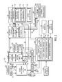
- FIG. 3 is a diagram of embodiment of the system 10 , further illustrating details of the SEGR gas turbine system 52 for use with the hydrocarbon production system 12 and/or other systems 84 .
- the SEGR gas turbine system 52 includes a gas turbine engine 150 coupled to the EG processing system 54 .
- the illustrated gas turbine engine 150 includes a compressor section 152 , a combustor section 154 , and an expander section or turbine section 156 .
- the compressor section 152 includes one or more exhaust gas compressors or compressor stages 158 , such as 1 to 20 stages of rotary compressor blades disposed in a series arrangement.
- the combustor section 154 includes one or more combustors 160 , such as 1 to 20 combustors 160 distributed circumferentially about a rotational axis 162 of the SEGR gas turbine system 52 .
- each combustor 160 may include one or more fuel nozzles 164 configured to inject the exhaust gas 66 , the oxidant 68 , and/or the fuel 70 .
- a head end portion 166 of each combustor 160 may house 1, 2, 3, 4, 5, 6, or more fuel nozzles 164 , which may inject streams or mixtures of the exhaust gas 66 , the oxidant 68 , and/or the fuel 70 into a combustion portion 168 (e.g., combustion chamber) of the combustor 160 .
- the fuel nozzles 164 may include any combination of premix fuel nozzles 164 (e.g., configured to premix the oxidant 68 and fuel 70 for generation of an oxidant/fuel premix flame) and/or diffusion fuel nozzles 164 (e.g., configured to inject separate flows of the oxidant 68 and fuel 70 for generation of an oxidant/fuel diffusion flame).
- Embodiments of the premix fuel nozzles 164 may include swirl vanes, mixing chambers, or other features to internally mix the oxidant 68 and fuel 70 within the nozzles 164 , prior to injection and combustion in the combustion chamber 168 .
- the premix fuel nozzles 164 also may receive at least some partially mixed oxidant 68 and fuel 70 .
- each diffusion fuel nozzle 164 may isolate flows of the oxidant 68 and the fuel 70 until the point of injection, while also isolating flows of one or more diluents (e.g., the exhaust gas 66 , steam, nitrogen, or another inert gas) until the point of injection.
- each diffusion fuel nozzle 164 may isolate flows of the oxidant 68 and the fuel 70 until the point of injection, while partially mixing one or more diluents (e.g., the exhaust gas 66 , steam, nitrogen, or another inert gas) with the oxidant 68 and/or the fuel 70 prior to the point of injection.
- one or more diluents may be injected into the combustor (e.g., into the hot products of combustion) either at or downstream from the combustion zone, thereby helping to reduce the temperature of the hot products of combustion and reduce emissions of NO X (e.g., NO and NO 2 ).
- the SEGR gas turbine system 52 may be controlled to provide substantially stoichiometric combustion of the oxidant 68 and fuel 70 .
- the fuel 70 and oxidant 68 generally do not mix upstream from the diffusion flame, but rather the fuel 70 and oxidant 68 mix and react directly at the flame surface and/or the flame surface exists at the location of mixing between the fuel 70 and oxidant 68 .
- the fuel 70 and oxidant 68 separately approach the flame surface (or diffusion boundary/interface), and then diffuse (e.g., via molecular and viscous diffusion) along the flame surface (or diffusion boundary/interface) to generate the diffusion flame.
- the fuel 70 and oxidant 68 may be at a substantially stoichiometric ratio along this flame surface (or diffusion boundary/interface), which may result in a greater flame temperature (e.g., a peak flame temperature) along this flame surface.
- the stoichiometric fuel/oxidant ratio generally results in a greater flame temperature (e.g., a peak flame temperature), as compared with a fuel-lean or fuel-rich fuel/oxidant ratio.
- the diffusion flame may be substantially more stable than a premix flame, because the diffusion of fuel 70 and oxidant 68 helps to maintain a stoichiometric ratio (and greater temperature) along the flame surface.
- the disclosed embodiments use one or more diluents to help control the temperature and emissions while still avoiding any premixing of the fuel 70 and oxidant 68 .
- the disclosed embodiments may introduce one or more diluents separate from the fuel 70 and oxidant 68 (e.g., after the point of combustion and/or downstream from the diffusion flame), thereby helping to reduce the temperature and reduce the emissions (e.g., NO X emissions) produced by the diffusion flame.
- the compressor section 152 receives and compresses the exhaust gas 66 from the EG processing system 54 , and outputs a compressed exhaust gas 170 to each of the combustors 160 in the combustor section 154 .
- additional exhaust gas or products of combustion 172 i.e., combustion gas
- the turbine section 156 includes one or more turbines or turbine stages 174 , which may include a series of rotary turbine blades.
- the machinery 106 may include a variety of equipment coupled to either end of the SEGR gas turbine system 52 , such as machinery 106 , 178 coupled to the turbine section 156 and/or machinery 106 , 180 coupled to the compressor section 152 .
- the machinery 106 , 178 , 180 may include one or more electrical generators, oxidant compressors for the oxidant 68 , fuel pumps for the fuel 70 , gear boxes, or additional drives (e.g. steam turbine 104 , electrical motor, etc.) coupled to the SEGR gas turbine system 52 .
- the turbine section 156 outputs the exhaust gas 60 to recirculate along the exhaust recirculation path 110 from an exhaust outlet 182 of the turbine section 156 to an exhaust inlet 184 into the compressor section 152 .
- the exhaust gas 60 passes through the EG processing system 54 (e.g., the HRSG 56 and/or the EGR system 58 ) as discussed in detail above.
- each combustor 160 in the combustor section 154 receives, mixes, and stoichiometrically combusts the compressed exhaust gas 170 , the oxidant 68 , and the fuel 70 to produce the additional exhaust gas or products of combustion 172 to drive the turbine section 156 .
- the oxidant 68 is compressed by an oxidant compression system 186 , such as a main oxidant compression (MOC) system (e.g., a main air compression (MAC) system) having one or more oxidant compressors (MOCs).
- the oxidant compression system 186 includes an oxidant compressor 188 coupled to a drive 190 .
- the drive 190 may include an electric motor, a combustion engine, or any combination thereof.
- the drive 190 may be a turbine engine, such as the gas turbine engine 150 .
- the oxidant compression system 186 may be an integral part of the machinery 106 .
- the compressor 188 may be directly or indirectly driven by the mechanical power 72 supplied by the shaft 176 of the gas turbine engine 150 .
- the drive 190 may be excluded, because the compressor 188 relies on the power output from the turbine engine 150 .
- a first oxidant compressor e.g., a low pressure (LP) oxidant compressor
- LP low pressure
- HP high pressure
- the oxidant compression system 186 is separate from the machinery 106 .
- the compression system 186 compresses and supplies the oxidant 68 to the fuel nozzles 164 and the combustors 160 .
- some or all of the machinery 106 , 178 , 180 may be configured to increase the operational efficiency of the compression system 186 (e.g., the compressor 188 and/or additional compressors).
- the variety of components of the machinery 106 may be disposed along the line of the shaft 176 and/or parallel to the line of the shaft 176 in one or more series arrangements, parallel arrangements, or any combination of series and parallel arrangements.
- the machinery 106 , 178 , 180 may include any series and/or parallel arrangement, in any order, of: one or more gearboxes (e.g., parallel shaft, epicyclic gearboxes), one or more compressors (e.g., oxidant compressors, booster compressors such as EG booster compressors), one or more power generation units (e.g., electrical generators), one or more drives (e.g., steam turbine engines, electrical motors), heat exchange units (e.g., direct or indirect heat exchangers), clutches, or any combination thereof.
- the compressors may include axial compressors, radial or centrifugal compressors, or any combination thereof, each having one or more compression stages.
- direct heat exchangers may include spray coolers (e.g., spray intercoolers), which inject a liquid spray into a gas flow (e.g., oxidant flow) for direct cooling of the gas flow.
- Indirect heat exchangers may include at least one wall (e.g., a shell and tube heat exchanger) separating first and second flows, such as a fluid flow (e.g., oxidant flow) separated from a coolant flow (e.g., water, air, refrigerant, or any other liquid or gas coolant), wherein the coolant flow transfers heat from the fluid flow without any direct contact.
- a fluid flow e.g., oxidant flow
- coolant flow e.g., water, air, refrigerant, or any other liquid or gas coolant
- Examples of indirect heat exchangers include intercooler heat exchangers and heat recovery units, such as heat recovery steam generators.
- the heat exchangers also may include heaters. As discussed in further detail below, each of these machinery components may be used
- the machinery 106 , 178 , 180 may be configured to increase the efficiency of the compression system 186 by, for example, adjusting operational speeds of one or more oxidant compressors in the system 186 , facilitating compression of the oxidant 68 through cooling, and/or extraction of surplus power.
- the disclosed embodiments are intended to include any and all permutations of the foregoing components in the machinery 106 , 178 , 180 in series and parallel arrangements, wherein one, more than one, all, or none of the components derive power from the shaft 176 .
- TABLE 1 depicts some non-limiting examples of arrangements of the machinery 106 , 178 , 180 disposed proximate and/or coupled to the compressor and turbine sections 152 , 156 .
- a cooling unit is represented as CLR
- a clutch is represented as CLU
- a drive is represented by DRV
- a gearbox is represented as GBX
- a generator is represented by GEN
- a heating unit is represented by HTR
- a main oxidant compressor unit is represented by MOC
- low pressure and high pressure variants being represented as LP MOC and HP MOC, respectively
- a steam generator unit is represented as STGN.
- any cell including two or more components is intended to cover a parallel arrangement of the components.
- TABLE 1 is not intended to exclude any non-illustrated permutations of the machinery 106 , 178 , 180 .
- These components of the machinery 106 , 178 , 180 may enable feedback control of temperature, pressure, and flow rate of the oxidant 68 sent to the gas turbine engine 150 .
- the oxidant 68 and the fuel 70 may be supplied to the gas turbine engine 150 at locations specifically selected to facilitate isolation and extraction of the compressed exhaust gas 170 without any oxidant 68 or fuel 70 degrading the quality of the exhaust gas 170 .
- the EG supply system 78 is disposed between the gas turbine engine 150 and the target systems (e.g., the hydrocarbon production system 12 and the other systems 84 ).
- the EG supply system 78 e.g., the EG extraction system (EGES) 80
- the extraction points 76 may be located between adjacent compressor stages, such as 2, 3, 4, 5, 6, 7, 8, 9, or 10 interstage extraction points 76 between compressor stages. Each of these interstage extraction points 76 provides a different temperature and pressure of the extracted exhaust gas 42 .
- the extraction points 76 may be located between adjacent turbine stages, such as 2, 3, 4, 5, 6, 7, 8, 9, or 10 interstage extraction points 76 between turbine stages. Each of these interstage extraction points 76 provides a different temperature and pressure of the extracted exhaust gas 42 .
- the extraction points 76 may be located at a multitude of locations throughout the combustor section 154 , which may provide different temperatures, pressures, flow rates, and gas compositions.
- Each of these extraction points 76 may include an EG extraction conduit, one or more valves, sensors, and controls, which may be used to selectively control the flow of the extracted exhaust gas 42 to the EG supply system 78 .
- the extracted exhaust gas 42 which is distributed by the EG supply system 78 , has a controlled composition suitable for the target systems (e.g., the hydrocarbon production system 12 and the other systems 84 ).
- the exhaust gas 170 may be substantially isolated from injection points (or flows) of the oxidant 68 and the fuel 70 .
- the EG supply system 78 may be specifically designed to extract the exhaust gas 170 from the gas turbine engine 150 without any added oxidant 68 or fuel 70 .
- the extracted exhaust gas 42 may be substantially free of oxygen and fuel.
- the EG supply system 78 may route the extracted exhaust gas 42 directly or indirectly to the hydrocarbon production system 12 and/or other systems 84 for use in various processes, such as enhanced oil recovery, carbon sequestration, storage, or transport to an offsite location.
- the EG supply system 78 includes the EG treatment system (EGTS) 82 for further treatment of the exhaust gas 42 , prior to use with the target systems.
- the EG treatment system 82 may purify and/or separate the exhaust gas 42 into one or more streams 95 , such as the CO 2 rich, N 2 lean stream 96 , the intermediate concentration CO 2 , N 2 stream 97 , and the CO 2 lean, N 2 rich stream 98 .
- These treated exhaust gas streams 95 may be used individually, or in any combination, with the hydrocarbon production system 12 and the other systems 84 (e.g., the pipeline 86 , the storage tank 88 , and the carbon sequestration system 90 ).
- the EG processing system 54 may include a plurality of exhaust gas (EG) treatment components 192 , such as indicated by element numbers 194 , 196 , 198 , 200 , 202 , 204 , 206 , 208 , and 210 .
- EG treatment components 192 e.g., 194 through 210
- the EG treatment components 192 may include any series and/or parallel arrangement, in any order, of: one or more heat exchangers (e.g., heat recovery units such as heat recovery steam generators, condensers, coolers, or heaters), catalyst systems (e.g., oxidation catalyst systems), particulate and/or water removal systems (e.g., inertial separators, coalescing filters, water impermeable filters, and other filters), chemical injection systems, solvent based treatment systems (e.g., absorbers, flash tanks, etc.), carbon capture systems, gas separation systems, gas purification systems, and/or a solvent based treatment system, or any combination thereof.
- heat exchangers e.g., heat recovery units such as heat recovery steam generators, condensers, coolers, or heaters
- catalyst systems e.g., oxidation catalyst systems
- particulate and/or water removal systems e.g., inertial separators, coalescing filters, water impermeable filters, and other filters
- the catalyst systems may include an oxidation catalyst, a carbon monoxide reduction catalyst, a nitrogen oxides reduction catalyst, an aluminum oxide, a zirconium oxide, a silicone oxide, a titanium oxide, a platinum oxide, a palladium oxide, a cobalt oxide, or a mixed metal oxide, or a combination thereof.
- the disclosed embodiments are intended to include any and all permutations of the foregoing components 192 in series and parallel arrangements. As illustrated below, TABLE 2 depicts some non-limiting examples of arrangements of the components 192 along the exhaust recirculation path 110 .
- a catalyst unit is represented by CU
- an oxidation catalyst unit is represented by OCU
- a booster blower is represented by BB
- a heat exchanger is represented by HX
- a heat recovery unit is represented by HRU
- a heat recovery steam generator is represented by HRSG
- a condenser is represented by COND
- a steam turbine is represented by ST
- a particulate removal unit is represented by PRU
- a moisture removal unit is represented by MRU
- a filter is represented by FIL
- a coalescing filter is represented by CFIL
- WFIL water impermeable filter
- INER inertial separator
- a diluent supply system e.g., steam, nitrogen, or other inert gas
- TABLE 2 illustrates the components 192 in sequence from the exhaust outlet 182 of the turbine section 156 toward the exhaust inlet 184 of the compressor section 152
- TABLE 2 is also intended to cover the reverse sequence of the illustrated components 192 .
- any cell including two or more components is intended to cover an integrated unit with the components, a parallel arrangement of the components, or any combination thereof.
- the HRU, the HRSG, and the COND are examples of the HE; the HRSG is an example of the HRU; the COND, WFIL, and CFIL are examples of the WRU; the INER, FIL, WFIL, and CFIL are examples of the PRU; and the WFIL and CFIL are examples of the FIL.
- TABLE 2 is not intended to exclude any non-illustrated permutations of the components 192 .
- the illustrated components 192 e.g., 194 through 210
- these EG treatment components 192 may enable feedback control of temperature, pressure, flow rate, and gas composition, while also removing moisture and particulates from the exhaust gas 60 .
- the treated exhaust gas 60 may be extracted at one or more extraction points 76 for use in the EG supply system 78 and/or recirculated to the exhaust inlet 184 of the compressor section 152 .
- the SEGR gas turbine system 52 may bleed off a portion of the compressed exhaust gas along one or more lines 212 (e.g., bleed conduits or bypass conduits).
- Each line 212 may route the exhaust gas into one or more heat exchangers 214 (e.g., cooling units), thereby cooling the exhaust gas for recirculation back into the SEGR gas turbine system 52 .
- a portion of the cooled exhaust gas may be routed to the turbine section 156 along line 212 for cooling and/or sealing of the turbine casing, turbine shrouds, bearings, and other components.
- the SEGR gas turbine system 52 does not route any oxidant 68 (or other potential contaminants) through the turbine section 156 for cooling and/or sealing purposes, and thus any leakage of the cooled exhaust gas will not contaminate the hot products of combustion (e.g., working exhaust gas) flowing through and driving the turbine stages of the turbine section 156 .
- a portion of the cooled exhaust gas may be routed along line 216 (e.g., return conduit) to an upstream compressor stage of the compressor section 152 , thereby improving the efficiency of compression by the compressor section 152 .
- the heat exchanger 214 may be configured as an interstage cooling unit for the compressor section 152 . In this manner, the cooled exhaust gas helps to increase the operational efficiency of the SEGR gas turbine system 52 , while simultaneously helping to maintain the purity of the exhaust gas (e.g., substantially free of oxidant and fuel).
- FIG. 4 is a flow chart of an embodiment of an operational process 220 of the system 10 illustrated in FIGS. 1-3 .
- the process 220 may be a computer implemented process, which accesses one or more instructions stored on the memory 122 and executes the instructions on the processor 120 of the controller 118 shown in FIG. 2 .
- each step in the process 220 may include instructions executable by the controller 118 of the control system 100 described with reference to FIG. 2 .
- the process 220 may begin by initiating a startup mode of the SEGR gas turbine system 52 of FIGS. 1-3 , as indicated by block 222 .
- the startup mode may involve a gradual ramp up of the SEGR gas turbine system 52 to maintain thermal gradients, vibration, and clearance (e.g., between rotating and stationary parts) within acceptable thresholds.
- the process 220 may begin to supply a compressed oxidant 68 to the combustors 160 and the fuel nozzles 164 of the combustor section 154 , as indicated by block 224 .
- the compressed oxidant may include a compressed air, oxygen, oxygen-enriched air, oxygen-reduced air, oxygen-nitrogen mixtures, or any combination thereof.
- the oxidant 68 may be compressed by the oxidant compression system 186 illustrated in FIG. 3 .
- the process 220 also may begin to supply fuel to the combustors 160 and the fuel nozzles 164 during the startup mode 222 , as indicated by block 226 .
- the process 220 also may begin to supply exhaust gas (as available) to the combustors 160 and the fuel nozzles 164 , as indicated by block 228 .
- the fuel nozzles 164 may produce one or more diffusion flames, premix flames, or a combination of diffusion and premix flames.
- the exhaust gas 60 being generated by the gas turbine engine 156 may be insufficient or unstable in quantity and/or quality. Accordingly, during the startup mode, the process 220 may supply the exhaust gas 66 from one or more storage units (e.g., storage tank 88 ), the pipeline 86 , other SEGR gas turbine systems 52 , or other exhaust gas sources.
- the process 220 may then combust a mixture of the compressed oxidant, fuel, and exhaust gas in the combustors 160 to produce hot combustion gas 172 , as indicated by block 230 by the one or more diffusion flames, premix flames, or a combination of diffusion and premix flames.
- the process 220 may be controlled by the control system 100 of FIG. 2 to facilitate stoichiometric combustion (e.g., stoichiometric diffusion combustion, premix combustion, or both) of the mixture in the combustors 160 of the combustor section 154 .
- the hot combustion gas 172 may have greater amounts of residual oxidant 68 and/or fuel 70 than during a steady state mode as discussed in further detail below.
- the process 220 may execute one or more control instructions to reduce or eliminate the residual oxidant 68 and/or fuel 70 in the hot combustion gas 172 during the startup mode.
- the process 220 then drives the turbine section 156 with the hot combustion gas 172 , as indicated by block 232 .
- the hot combustion gas 172 may drive one or more turbine stages 174 disposed within the turbine section 156 .
- the process 220 may treat the exhaust gas 60 from the final turbine stage 174 , as indicated by block 234 .
- the exhaust gas treatment 234 may include filtration, catalytic reaction of any residual oxidant 68 and/or fuel 70 , chemical treatment, heat recovery with the HRSG 56 , and so forth.
- the process 220 may also recirculate at least some of the exhaust gas 60 back to the compressor section 152 of the SEGR gas turbine system 52 , as indicated by block 236 .
- the exhaust gas recirculation 236 may involve passage through the exhaust recirculation path 110 having the EG processing system 54 as illustrated in FIGS. 1-3 .
- the recirculated exhaust gas 66 may be compressed in the compressor section 152 , as indicated by block 238 .
- the SEGR gas turbine system 52 may sequentially compress the recirculated exhaust gas 66 in one or more compressor stages 158 of the compressor section 152 .
- the compressed exhaust gas 170 may be supplied to the combustors 160 and fuel nozzles 164 , as indicated by block 228 .
- Steps 230 , 232 , 234 , 236 , and 238 may then repeat, until the process 220 eventually transitions to a steady state mode, as indicated by block 240 .
- the process 220 may continue to perform the steps 224 through 238 , but may also begin to extract the exhaust gas 42 via the EG supply system 78 , as indicated by block 242 .
- the exhaust gas 42 may be extracted from one or more extraction points 76 along the compressor section 152 , the combustor section 154 , and the turbine section 156 as indicated in FIG. 3 .
- the process 220 may supply the extracted exhaust gas 42 from the EG supply system 78 to the hydrocarbon production system 12 , as indicated by block 244 .
- the hydrocarbon production system 12 may then inject the exhaust gas 42 into the earth 32 for enhanced oil recovery, as indicated by block 246 .
- the extracted exhaust gas 42 may be used by the exhaust gas injection EOR system 112 of the EOR system 18 illustrated in FIGS. 1-3 .
- the compressed exhaust gas 170 circulates from the compressor section 152 (e.g., exhaust gas compressor) to the turbine section 156 through the combustor section 154 (e.g., turbine combustor) along a catalytic flow path.
- the exhaust gas 170 may flow along the catalytic flow path in the steps indicated by blocks 238 , 228 , 230 , and 232 .
- FIG. 5 illustrates a method 300 of directing the exhaust gas flow 170 along the catalytic flow path.
- the catalytic flow path directs at least the compressed exhaust gas 170 through one or more catalytic converters to react with products of incomplete combustion in the compressed exhaust gas 170 .
- the catalytic flow path may direct the exhaust gas 170 through one or more catalytic converters with an oxidation catalyst, a carbon monoxide catalyst, or other type of catalyst.
- the one or more catalytic converters may react with at least some of the products of incomplete combustion in the compressed exhaust gas 170 (e.g., nitrogen oxides, carbon monoxide, sulfur oxides, hydrogen, oxygen, unburnt hydrocarbons, and other products).
- the one or more catalytic converters may also react with oxidant 68 or fuel 70 with the compressed exhaust gas 170 .
- the catalytic converter may react with oxidant 68 (e.g., oxygen), carbon monoxide, and/or nitrogen oxides.
- the catalytic converter may convert carbon monoxide to carbon dioxide, reduce nitrogen oxides, reduce free oxygen (e.g., O 2 ) concentrations, or any combination thereof.
- the one or more catalytic converters described herein may increase the concentration and/or increase the purity of carbon dioxide in an exhaust gas flow utilized for enhanced oil recovery.
- FIG. 5 illustrates multiple catalytic conversion blocks 302 along the catalytic flow path at which a catalytic converter reacts with the compressed exhaust gas 170 .
- the catalytic reaction may be exothermic and warm the compressed exhaust gas 170 , thereby adding heat to the combustion reaction occurring in the combustors 160 .
- the added heat may help improve the stability and efficiency of combustion, and provide more energy to be extracted via the turbine section.
- the method 300 of directing the compressed exhaust gas flow 170 along the catalytic flow path may include one or more of the catalytic conversion blocks 302 .
- the compressor section 152 compresses the exhaust gas at block 228 .
- the compressed exhaust gas 170 is directed from the compressor section 152 directly to a catalytic converter to react with the compressed exhaust gas 170 , as indicated at block 304 .
- the method 300 of FIG. 5 illustrates non-limiting examples of catalytic flow routes 306 , 307 , and 308 by which the compressed exhaust gas 170 may leave the compressor section 152 .
- the first catalytic flow route 306 mixes the compressed exhaust gas 170 with fuel 70 at block 310 , then mixes the compressed exhaust gas 170 and fuel 70 with the oxidant 68 at block 312 .
- the first catalytic flow route 306 may include catalytic conversion of the compressed exhaust gas 170 as indicated by blocks 314 and 316 . Accordingly, the compressed exhaust gas 170 may be catalytically converted after mixing with the fuel 70 or the oxidant 68 .
- the second catalytic flow route 308 mixes the compressed exhaust gas 170 with the oxidant 68 at block 318 , then mixes the compressed exhaust gas 170 and oxidant 68 with fuel 70 at block 320 .
- the second catalytic flow route 308 may include catalytic conversion of the compressed exhaust gas 170 as indicated by blocks 322 and 324 .
- the first and second catalytic flow routes 306 , 308 may direct the compressed exhaust gas 170 , fuel 70 , and oxidant 68 to one or more premix fuel nozzles 164 . Accordingly, the compressed exhaust gas 170 may be catalytically converted after mixing with the oxidant 68 or fuel 70 .
- the method 300 may direct the compressed exhaust gas 170 along the first catalytic flow routes 306 and/or the second catalytic flow routes 308 based at least in part on the composition of the compressed exhaust gas 170 . For example, the catalytic conversion at block 314 with a first catalyst material may react better with a compressed exhaust gas 170 that has more unburnt fuel than the catalytic conversion at block 322 with a different second catalyst material.
- the method 300 mixes the compressed exhaust gas 170 with the oxidant 68 and the fuel 70 into a mixture approximately simultaneously, or the oxidant 68 and the fuel 70 may be premixed before mixing with the compressed exhaust gas 170 .
- Blocks 306 to 324 of FIG. 5 may occur within the fuel nozzles 164 and/or head end portion 166 of the combustor 160 . Additionally, at least some of blocks 306 to 324 may be sub-steps of blocks 224 , 226 , and 228 shown in FIG. 4 .
- the compressed exhaust gas 170 may leave the compressor section 152 along the third catalytic flow route 307 , such as for a diffusion flame within the combustor 160 .
- the compressed exhaust gas 170 may mix the fuel 70 (block 310 ) separately from mixing with the oxidant 68 (block 318 ).
- the compressed exhaust gas 170 may dilute the fuel 70 at block 310 and/or dilute the oxidant 68 at block 318 .
- the fuel 70 and any compressed exhaust gas 170 may be isolated from the oxidant 68 and any compressed exhaust gas 170 at block 325 .
- the fuel mixture and oxidant mixture are separated at block 325 and injected into the combustor 160 separately via one or more diffusion flame nozzles 164 . Accordingly, the oxidant 68 , fuel 70 , and compressed exhaust gas 170 may mix approximately at the diffusion flame within the combustor 160 .
- the compressed exhaust gas 170 , oxidant 68 , and fuel 70 may be combusted in the combustor 160 as indicated by block 230 of FIGS. 4 and 5 .
- the compressed exhaust gas 170 , oxidant 68 , and fuel 70 may be mixed prior to injection into the combustor 160 via one or more premix fuel nozzles, mixed in the combustion chamber 160 via one or more diffusion flame nozzles, or any combination thereof.
- the composition of the mixture changes along the catalytic flow path through the combustor 160 as the mixture combusts.
- the oxidant 68 and the fuel 70 may combust initially in a reaction zone 326 .
- the combustion releases heat and breaks down the fuel 70 with the oxidant 68 and compressed exhaust gas 170 into the combustion gases 172 .
- Compressed exhaust gas 170 , compressed oxidant 68 , and/or another diluent may enter the combustor 160 in a dilution zone 328 , at least in part to cool the combustor 160 and/or combustion gas 172 downstream of the reaction zone 236 .
- Gases entering the dilution zone 328 may reduce the formation and/or concentrations of nitrogen oxides by reducing the temperature within the combustor 160 .
- some diffusion flame nozzles may improve stoichiometric combustion, resulting in higher flame temperatures.
- Dilution gases may cool the combustor 160 and/or flame to reduce the formation of nitrogen oxides.
- the catalytic flow path passes through a transition piece 330 of the combustor section 154 prior to entering the turbine section 156 .
- the hot combustion gas 172 may drive the turbine stages 174 as indicated at block 332 .
- one or more catalytic converters in the combustor section 154 convert the compressed exhaust gas 170 and/or combustion gas 172 along the catalytic flow path prior to the turbine section 156 .
- some of the combustion mixture may undergo catalytic conversion at block 334 , which may be located at or between the reaction zone 326 and the dilution zone 328 .
- the compressed exhaust gas 170 and/or combustion gas 172 may undergo catalytic conversion at block 336 after entering the dilution zone 328 .
- the combustion gas 172 may undergo catalytic conversion at block 338 after entering the transition piece 330 .
- the method 300 of directing the compressed exhaust gas 170 from the compressor section 152 to the turbine section 156 may include catalytic conversion with any combination of one or more blocks 302 as shown in FIG. 5 .
- FIG. 6 is a schematic illustrating some of the locations within the gas turbine system 52 where the catalytic conversion may occur in one or more catalytic converters 350 .
- the combustion gas 172 enters the turbine section 156 from the combustor section 154 .
- the turbine section 156 outputs the exhaust gas 60 to recirculate along the exhaust recirculation path 110 from the exhaust outlet 182 to the exhaust inlet 184 into the compressor section 152 .
- the compressor section 152 compresses the exhaust gas 66 and directs the compressed exhaust gas 170 along the catalytic flow path 352 .
- fluids e.g., exhaust gas 66
- fluids may flow along the catalytic flow path 352 and the exhaust recirculation path 110 in a loop until extracted into an exhaust gas supply system 78 and/or vented.
- the one or more catalytic converters 350 react with at least some of the products (e.g., nitrogen oxides, carbon monoxide, sulfur oxides, hydrogen, oxygen, unburnt hydrocarbons, and other products) of incomplete combustion in the fluid flows along the catalytic flow path 352 .
- the one or more catalytic converters 350 may be arranged within the SEGR gas turbine system 52 to increase the concentration of carbon dioxide in the compressed exhaust gas 170 for use in enhanced oil recovery, to increase the heat added to the combustion mixture prior to expansion in the turbine section 156 for improved energy efficiency or energy attraction, or to affect the stoichiometry of the combustion, or any combination thereof.
- the one or more catalytic converters 350 may aid diffusion flame combustion by reacting with residual materials along a flow route.
- compressed exhaust gas 170 may be added to a fuel flow path to reduce the concentration of oxidant 68 in the fuel flow path prior to entering the combustor via the diffusion flame nozzle 164 .
- compressed exhaust gas 170 may be added to an oxidant flow path to reduce the concentration of fuel 70 in the oxidant flow path prior to entering the combustor via the diffusion flame nozzle 164 .
- the catalytic converters 350 are numbered below for ease of reference as to the arrangement relative to the SEGR gas turbine system 52 .
- Presently contemplated embodiments of the SEGR gas turbine system 52 are not limited to the locations or quantity of the catalytic converters 350 described below.
- Embodiments of the SEGR gas turbine system 52 may include any one or more of the catalytic converters 354 , 356 , 358 , 360 , and 362 , or any combination thereof.
- an embodiment of the SEGR gas turbine system 52 may include a first catalytic converter 354 and a second catalytic converter 356 , but not a third catalytic converter 358 , a fourth catalytic converter 360 , or a fifth catalytic converter 362 .
- the SEGR gas turbine system 52 may include a second catalytic converter 356 and a fifth catalytic converter 362 . Another embodiment may include only a first catalytic converter 354 . In some embodiments, the SEGR gas turbine system 52 may include approximately 1, 2, 3, 4, 5, 6, 7, 8, 9, 10 or more catalytic converters 350 positioned along the catalytic flow path 352 between the compressor section 152 and the turbine section 156 .
- the catalytic converters 350 may include compositions of an oxidation catalyst, a carbon monoxide catalyst, an aluminum oxide, a zirconium oxide, a silicone oxide, a titanium oxide, a platinum oxide, a palladium oxide, a cobalt oxide, or a mixed metal oxide, or any combination thereof.
- the catalyst compositions may react to convert carbon monoxide to carbon dioxide, to reduce oxygen (O 2 ) concentrations, to convert nitrogen oxides into nitrogen (N 2 ) and water (H 2 O), or any combination thereof.
- each of the catalytic converters 350 has substantially the same catalyst composition.
- the catalytic converters 350 have different catalyst compositions based at least in part on the location of the catalytic converter 350 .
- a catalytic converter 350 proximate to the compressor section 152 may include a catalyst with a relatively strong and/or fast reaction to unburnt hydrocarbons
- a catalytic converter 350 proximate to the turbine section 156 may include a catalyst with a relatively strong and/or fast reaction to oxides (e.g., nitrogen oxides, carbon monoxide, and/or sulfur oxides).
- Some catalytic converters 350 may primarily react with only the compressed exhaust gas 170 , only the fuel 70 , or only the oxidant 68 .
- the catalytic converters 350 may react with compressed exhaust gas 170 , the fuel 70 , or the oxidant 68 , or any combination thereof. Reactions within the catalytic converters 350 may release additional energy in the form of heat to the compressed exhaust gas 170 , the fuel 70 , and/or the oxidant 68 .
- the released heat from the catalytic converter 350 reduces the heat consumption of the HRSG 56 and increases the efficiency of the SEGR gas turbine system 52 .
- Warmed constituents of the air/fuel mixture may enable the control system 100 to reduce the intake of the fuel 70 and/or the oxidant 68 for combustion. That is, the released heat from the catalytic converter 350 enables less fuel 70 and/or less oxidant 68 to be combusted without substantially affecting the temperature (or energy) of the combustion gases 172 directed to the turbine section 156 . Furthermore, heat added to the SEGR gas turbine system 52 may enable the energy from the additional heat to be extracted in the topping cycle (e.g., gas turbine system) rather than in a bottoming cycle (e.g., steam turbine system). In some embodiments, one or more catalytic converters 350 may increase a net efficiency of the SEGR gas turbine system 52 by more than approximately 0.1, 0.2, 0.3, 0.5, 1.0, 1.5, 2.0, or 2.5%,
- the SEGR gas turbine system 52 may include the first catalytic converter 354 arranged between the compressor section 152 and the one or more fuel nozzles 164 .
- the first catalytic converter 354 also receives and reacts with the compressed exhaust gas 170 .
- the first catalytic converter 354 may receive and react with the oxidant 68 and/or the fuel 70 .
- first catalytic converter 354 may receive and react with one of the oxidant 68 and the fuel 70 separately to isolate the other of the oxidant 68 and the fuel 70 prior to the mixing in the combustor 160 .
- the first catalytic converter 354 may be arranged internal or external to the gas turbine system (e.g., compressor section 152 , combustor section 154 , and turbine section 156 ).
- the second catalytic converter 356 may be arranged with the one or more fuel nozzles 164 at the head-end portion 166 in the combustor section 154 .
- the second catalytic converter 356 receives the compressed exhaust gas 170 , and may receive the oxidant 68 and/or the fuel 70 as described with the first catalytic converter 354 .
- each of the one or more fuel nozzles 164 may have a second catalytic converter 356 .
- only some of the fuel nozzles 164 may have a second catalytic converter 356 , such as approximately 10, 20, 25, 50, or 75% of the fuel nozzles 164 .
- the second catalytic converters 356 may be arranged upstream of the one or more fuel nozzles 164 , within the one or more fuel nozzles 164 , or at a downstream end of the one or more fuel nozzles 164 adjacent to a combustion chamber 168 .
- the first catalytic converter 354 and/or the second catalytic converter 356 may affect the equivalence ratio of the stoichiometric combustion of the oxidant/fuel/exhaust gas mixture.
- the catalytic converters 350 may improve the efficiency of the stoichiometric combustion and reduce the concentrations of products of incomplete combustion of the combustion gas 172 . As a result, overall combustion efficiency and net cycle efficiency may be improved.
- the catalytic converter 350 may reduce the amount of carbon monoxide and increase the amount of carbon dioxide by converting the carbon monoxide to carbon dioxide.
- the carbon dioxide may be used to increase the effectiveness of the exhaust gas 170 for enhanced oil recovery.
- the catalytic converters 350 may reduce the concentrations of carbon monoxide by approximately 90, 95, 96, 97, 98, or 99%.
- the first catalytic converter 354 and/or the second catalytic converter 356 may warm the compressed exhaust gas 170 through the catalytic reaction.
- the released heat energy may reduce exergetic losses due to temperature differences between the compressed exhaust gas 170 and the oxidant 68 .
- one or more of the first catalytic converter 354 or second catalytic converter 356 may increase the temperature (e.g., compressor discharge temperature) of the compressed exhaust gas 170 by approximately 8° C. (15° F.), 14° C. (25° F.), 28° C.
- the first catalytic converter 354 may increase the compressor discharge temperature of the compressed exhaust gas 170 from approximately 427° C. (800° F.) to approximately 449° C. (840° F.), or from approximately 427° C. (800° F.) to approximately 493° C. (920° F.).
- the third catalytic converter 358 may be arranged within the reaction zone 326 of the combustor 160 .
- the third catalytic converter 358 may affect the equivalence ratio of the stoichiometric combustion of the oxidant 68 and fuel 70 with the recirculated compressed exhaust gas 170 .
- the fourth catalytic converter 360 may be arranged within the dilution zone 328 of the combustor section 154 .
- the fourth catalytic converter 360 may react with the combustion gas 172 within the combustor 160 .
- the fourth catalytic converter 360 may react with the compressed exhaust gas 170 or other diluent (e.g., water, steam, etc.) used to dilute the combustion gas 172 and to cool components of the combustor 160 .
- other diluent e.g., water, steam, etc.
- the fifth catalytic converter 362 may be arranged within the transition piece 332 of the combustor section 154 .
- the fifth catalytic converter 362 may react with the combustion gas 172 to reduce the amount and concentration of undesirable combustion products (e.g., hydrogen, oxygen, sulfur) while adding heat prior to entering the turbine section 156 . Reducing the amount and concentration of some of the undesirable combustion products may increase the service life and/or reduce corrosion of components in the turbine section 156 , such as the turbine blades. Adding heat to the combustion gas 172 may increase the efficiency and available energy to extract through the turbine section 156 .
- the third, fourth, and fifth catalytic converters 358 , 360 , and 362 may increase the temperature of the combustion gases 172 by approximately 8° C. (15° F.), 14° C. (25° F.), 28° C. (50° F.), 56° C., (100° F.), or 112° C. (200° F.).
- FIG. 7 illustrates an embodiment of a catalytic converter 350 .
- the catalytic converter 350 may be positioned so that at least a first portion 380 of a fluid flow 382 along the catalytic flow path 352 flows through the catalytic converter 350 .
- the fluid flow 382 along the catalytic flow path 352 includes at least compressed exhaust gas 170 , and may include fuel 70 , oxidant 68 , and/or combustion gas 172 .
- the catalytic converter 350 is positioned such that substantially the entire fluid flow 382 flows through the catalytic converter 350 .
- the catalytic converter 350 is positioned such that a first portion 380 flows through the catalytic converter 350 , and a second portion 384 bypasses the catalytic converter 350 .
- a controller 383 may monitor the fluid flow 382 via one or more sensors 385 in a first wall 392 and control the split between the first portion 380 and the second portion 384 based on sensor feedback 130 regarding concentrations of oxidant 68 , fuel 70 , carbon dioxide, carbon monoxide, nitrogen oxides, combustion products, or other components.
- the controller 383 may control the split between the first portion 380 and the second portion 384 to control the heat, nitrogen oxide concentration of the fluid flow 382 , carbon dioxide concentration of the fluid flow 382 , stoichiometric combustion of the fluid flow 382 , or any combination thereof.
- the catalytic converter 350 may include one or more layers 386 with a catalyst material 388 .
- the one or more layers 386 may be arranged in an interior volume 390 between a first wall 392 and a second wall 394 .
- the first wall 392 is a portion of combustor liner 414 about the combustor 160
- the second wall 394 is a portion of a flow sleeve 412 .
- the first and second walls 392 , 394 are walls of a passage or interior volume between components of the SEGR gas turbine system 52 , such as between the compressor section 152 and the combustor section 154 .
- a layer 386 may be a porous catalytic membrane, filter, or film with an impregnated or coated catalyst material 388 .
- a layer 386 may be a ceramic bed with a fixed or loose catalyst material 388 .
- the catalyst material 388 may be an oxidation catalyst that causes oxidation of nitrogen oxides and/or sulfur oxides.
- the catalyst material 388 is a carbon monoxide catalyst that oxidizes with carbon monoxide to form carbon dioxide.
- the catalyst material 388 may include, but is not limited to, one or more of the following components: an aluminum oxide, a zirconium oxide, a silicone oxide, a titanium oxide, a platinum oxide, a palladium oxide, a cobalt oxide, or a mixed metal oxide.
- the layers 386 may be arranged in series or in parallel.
- the layers 386 of a catalytic converter 350 may include the same or different catalyst materials 388 .
- the catalytic converter 350 may be a coating, film, or passageway on a wall of a component along the catalytic flow path between the compressor section 152 and the combustor section 154 .
- a portion of the combustor liner 414 , flow sleeve 412 , head end wall, fuel nozzles 164 may be coated with the material of the catalytic converter 350 .
- the first and second walls 392 , 394 may be one wall that extends about the fluid flow 382 .
- the catalytic converter 350 may include one or more layers 386 , including, but not limited to, 1, 2, 3, 4, 5, 10, 15, 20, or more layers.
- the embodiment of FIG. 7 illustrates four layers 386 with the different catalyst materials 388 .
- the catalyst material 388 of a first layer 396 may react primarily with nitrogen oxides
- the catalyst material 388 of a second layer 398 may react primarily with carbon monoxide
- the catalyst material 388 of a third layer 400 may react primarily with unburnt hydrocarbons in the first portion 380 of the fluid flow 382 .
- each layer 386 has substantially the same catalyst material 388 .
- the catalyst material 388 may vary between catalytic converters 350 based at least in part on the position of the catalytic converter 350 .
- the portion 380 of the fluid flow 382 exiting the catalytic converter 350 along the catalytic flow path 352 may be warmer than the portion 380 of the fluid flow 382 entering the catalytic converter 350 .
- the portion 380 of the fluid flow 382 exiting the catalytic converter 350 may have a reduced concentration of carbon monoxide, nitrogen oxides, sulfur oxides, and/or unburnt fuel than the portion 380 entering the catalytic converter 350 .
- FIG. 8 illustrates a schematic of a compressor section 152 and combustor section 154 with one or more catalytic converters 350 .
- the one or more catalytic converters 350 may be arranged at various positions along the catalytic flow path 352 between the compressor section 152 and the turbine section 156 .
- the compressor section 152 directs the compressed exhaust gas 170 from the compressor stages 158 into a compressor discharge casing 410 , which encloses at least part of the combustor 160 of the combustor section 154 (e.g., the combustion chamber 168 ) surrounded by a combustor liner 414 and a flow sleeve 412 .
- the flow sleeve 412 may direct the compressed exhaust gas 170 to the head end portion 166 .
- the flow sleeve 412 also receives the oxidant 68 .
- Gas (e.g., oxidant 68 and/or compressed exhaust gas 170 ) within the flow sleeve 412 may cool the combustor liner 414 that encloses the combustion chamber 168 .
- the compressed exhaust gas 170 in the compressor discharge casing 410 may enter the flow sleeve 412 through passages 416 .
- Some of the compressed exhaust gas 170 , other diluent (e.g., steam, water), or oxidant 68 may enter the combustion chamber 168 through dilution holes 418 in the combustor liner 414 .
- the dilution holes 418 may direct the compressed exhaust gas 170 and/or oxidant 68 into the dilution zone 328 .
- some of the compressed exhaust gas 170 may be extracted through an extraction point 76 to the exhaust gas supply system 78 external to the compressor discharge casing 410 .
- a catalytic converter 419 may be at or near the extraction point 76 of the compressor discharge casing 410 .
- the exhaust gas supply system 78 may treat and supply the exhaust gas 42 to the hydrocarbon production system 12 , such as for enhanced oil recovery.
- one or more first catalytic converters 354 may be arranged internally within the compressor discharge casing 410 , such as between the flow sleeve 412 and the combustor liner 414 .
- an external passage 420 from the compressor discharge casing 410 may direct the compressed exhaust gas 170 to a first catalytic converter 354 external to the discharge casing 410 .
- one or more second catalytic converters 356 may be arranged within the head end portion 166 of the combustor section 154 .
- the second catalytic converters 356 are arranged upstream of the fuel nozzles 164 relative to the flow of the compressed exhaust gas 170 through the combustor section 154 .
- a cap 357 divides the combustor 160 into the head end portion 166 and the combustion portion 168 .
- the fuel nozzles 164 are positioned in the head end portion 166 , and flames, if any, from combustion occur within the combustion portion 168 .
- the second catalytic converters 356 are arranged within the one or more fuel nozzles 164 .
- the second catalytic converters 356 described above may be defined to be arranged internal to the SEGR gas turbine system 52 and the combustor section 154 .
- the first catalytic converters 354 described above may be arranged either internal or external to the SEGR gas turbine system 52 .
- Some embodiments of the combustor 160 may include a third catalytic converter 358 in the combustion zone 326 , a fourth catalytic converter 360 in the dilution zone 328 , and/or a fifth catalytic converter 362 in the transition piece 330 .
- the third, fourth, and/or fifth catalytic converters 358 , 360 , and 362 may enable substantially complete catalytic combustion of the oxidant 68 , fuel 70 , and compressed exhaust gas 170 mixture.
- Catalytic combustion may enable the release of energy from the fuel 70 substantially without a flame inside the combustor by catalytic reaction with the oxidant 68 and the fuel 70 .
- the SEGR gas turbine system 52 may release energy from the fuel 70 without a flame utilizing only catalytic converters 350 within the combustor 160 (e.g., third, fourth, and/or fifth catalytic converters 358 , 360 , and 362 ).
- Substantially complete catalytic combustion may be combustion with an equivalence ratio between approximately 0.90 to 1.10, such that the combustion gases 172 have reduced concentration levels of products of incomplete combustion.
- Catalytic combustion may reduce concentration levels of nitrogen oxides, carbon monoxide, sulfur oxides, hydrogen, oxygen, unburnt hydrocarbons, and other products of incomplete combustion.
- Catalytic combustion may enable reduced concentration levels of such products and/or low temperature combustion gas 172 relative to conventional combustion with a flame.
- Catalytic combustion may increase the production of carbon dioxide by converting carbon monoxide to carbon dioxide, and by reacting the oxidant 68 and the fuel 70 without a flame.
- the carbon dioxide may be utilized for enhanced oil recovery and other applications if extracted from the SEGR gas turbine system 52 .
- the combustion portion 154 may be arranged about an axis 422 with the combustor liner 414 and flow sleeve 412 extending circumferentially about the axis 422 .
- the combustion gases 172 flow through the combustion chamber 168 primarily in a downstream direction 424 toward the turbine section 156 .
- the compressed exhaust gas 170 and/or the oxidant 68 may flow toward the head end portion 166 from the compressor section 152 in an upstream direction 426 relative to the combustion gases 172 through the flow sleeve 412 .
- the one or more first and second catalytic converters 354 , 356 may be arranged within the combustor section 154 spaced in a radial direction 428 from the axis 422 .
- FIG. 9 illustrates an embodiment of the SEGR gas turbine system 52 with a catalytic converter 350 that may be used in catalytic partial oxidation (CPDX) combustion.
- the exhaust recirculation path 110 , compressor section 152 , and turbine section 156 of FIG. 9 may operate substantially similar as described above with FIGS. 3 and 6 .
- the sixth catalytic converter 440 may have several components, such as a reformer 442 , a shift reactor 444 , and a separation unit 446 .
- the reformer 442 may receive the fuel 70 and at least some of the compressed exhaust gas 170 and/or compressed oxidant 68 from the oxidant compressor 188 .
- the reformer 442 may convert (i.e., reform) the fuel 70 to a syngas 448 (e.g., hydrogen (H 2 ) and carbon monoxide) by partial oxidation and/or steam reforming.
- the compressed exhaust gas 170 may improve the partial oxidation of the fuel 70 into the syngas 448 .
- the shift reactor 444 receives the syngas 448 , compressed exhaust gas 170 , and oxidant 68 , and then converts (i.e., shifts) the syngas 448 into carbon dioxide 92 (CO 2 ) and hydrogen 450 (H 2 ).
- the shift reactor may convert the syngas 445 by a water-gas shift reaction.
- the separation unit 446 may separate the carbon dioxide 92 from the hydrogen 450 , and direct the hydrogen 450 to the one or more fuel nozzles 164 .
- the carbon dioxide 92 may be directed to a storage tank 88 or to a carbon sequestration system 90 .
- the separated carbon dioxide 92 may be utilized as a diluent gas and/or for enhanced oil recovery as described above.
- the hydrogen 450 , oxidant 68 , and compressed exhaust gas 170 may undergo stoichiometric combustion in the combustor section 154 .
- the stoichiometric combustion may be conventional combustion (e.g., with a flame) utilizing one or more premix fuel nozzles and/or one or more diffusion fuel nozzles.
- stoichiometric combustion may be catalytic combustion (e.g., without a flame).
- Some embodiments of the combustor section 154 may have one or more catalytic converters 350 in addition to the sixth catalytic converter 440 .
- FIG. 10 illustrates an embodiment of the system 10 with catalytic converters 350 along the catalytic flow path 352 between the compressor section 152 and the turbine section 156 of the SEGR gas turbine system 52 .
- one or more catalytic converters 350 may be arranged at any point along the catalytic flow path 352 to react with the compressed exhaust gas 170 and to reduce the concentration of products of incomplete combustion from the combustion gas 172 .
- the combustion gas 172 flows along the exhaust recirculation path 110 from the turbine section 156 into the HRSG 56 of the exhaust gas processing system 54 . In the HRSG 56 , heat is extracted in the bottoming cycle to produce steam 62 .
- the steam 62 is directed to the combined cycle system 102 with a steam turbine 104 to extract energy from the steam 62 , such as by driving machinery 106 (e.g., generator), to produce electricity.
- the heat from the HRSG 56 may be used in a fuel desulfurization system 460 and/or a fuel heating system 462 to treat the fuel 70 supplied to the one or more fuel nozzles 164 in the combustors 160 .
- a catalytic converter 350 may be arranged along the catalytic flow path 352 and another catalytic converter 350 may be arranged along the exhaust recirculation path 110 , such as within the HRSG 56 or the EGR system 58 .
- the catalytic converters 350 in the exhaust gas processing system 54 may reduce the concentrations of the oxidant 68 , unburnt fuel 70 , or other component materials.
- the catalytic converters 350 may convert carbon monoxide to carbon dioxide, thus increasing the concentration of carbon dioxide that may be used for enhanced oil recovery.
- the exhaust gas 62 that exits the HRSG 56 may pass through the EGR system 54 , or vice versa, along the exhaust recirculation path 110 before recirculating to the compressor section 152 .
- the compressor section 152 compresses the exhaust gas 66 separate from the oxidant compressor 188 (e.g., main air compressor).
- the compressor section 152 and/or the oxidant compressor 188 may be driven by the turbine section 156 and/or the steam turbine 104 .
- the oxidant 68 from the oxidant compressor 188 may mix with the compressed exhaust gas 170 and fuel 70 in the combustor 160 or the catalytic converter 350 .
- compressed nitrogen oxides, oxidant 68 , or other gases from the main air compressor 188 may be directed through a first valve 464 to mix with compressed exhaust gas 170 in the exhaust gas supply system 78 .
- the gases from the main air compressor 188 may react be used to reduce the concentrations of carbon monoxide in the compressed exhaust gas 170 .
- the exhaust gas supply system 78 may mix the main air compressor gases and the compressed exhaust gas 170 into a mixture 466 at a second valve 468 and cool the mixture 466 in a purge cooler 470 .
- the main air compressor gases may dilute the carbon monoxide concentrations in the mixture 466 .
- a catalytic converter 350 within the purge cooler 470 may reduce the concentration levels of products of incomplete combustion (e.g., carbon monoxide, nitrous oxides, etc.) in the mixture 466 by reacting with the oxidant 68 in the mixture 466 .
- the exhaust gas 42 may exit the exhaust gas supply system 78 as one or more streams 95 (e.g., first stream 96 , second stream 97 , third stream 98 ) with differing concentration levels of nitrogen (N 2 ) and carbon dioxide 92 (CO 2 ).
- the SEGR gas turbine systems 52 described above may utilize one or more catalytic converters 350 between the compressor section 152 and the turbine section 156 .
- one or more catalytic converters 350 may be arranged along an exhaust recirculation path 110 to reduce the concentrations of residual fuel 70 and/or oxidant 68 in the exhaust gas 66 .
- a combustor section 154 having one or more diffuser fuel nozzles 164 may separate the oxidant 68 and the fuel 70 until injection into the combustor 160 where the oxidant 68 and fuel 70 mix at the diffusion flame.
- the one or more catalytic converters 350 of the SEGR gas turbine system 52 may include compositions of an oxidation catalyst, a carbon monoxide catalyst, an aluminum oxide, a zirconium oxide, a silicone oxide, a titanium oxide, a platinum oxide, a palladium oxide, a cobalt oxide, or a mixed metal oxide, or any combination thereof.
- Gases with high concentrations of carbon dioxide may be utilized in enhanced oil recovery systems 18 .
- the gases used for EOR may have low concentrations (e.g., substantially zero) of oxidant 68 , fuel 70 , and/or other components (e.g., nitrogen oxides, water).
- the catalytic converters 350 may increase the concentrations of carbon dioxide in the exhaust gas 42 by converting carbon monoxide to carbon dioxide and by bringing the equivalence ratio to approximately 1.0 (e.g., between 0.95 and 1.05).
- the catalytic converters 350 described above may reduce the concentrations of oxidant 68 and fuel 70 in compressed exhaust gas 170 between the compressor section 152 and the turbine section 156 .
- the added heat from the catalytic converters between the compressor section 152 and the turbine section 156 may improve the flame stability and energy extraction from the SEGR gas turbine system 52 .
- the catalyst compositions may react to convert carbon monoxide to carbon dioxide, to reduce oxygen (O 2 ) concentrations, to convert nitrogen oxides into nitrogen (N 2 ) and water (H 2 O), or any combination thereof.
- the exhaust gas, or the carbon dioxide extracted from the exhaust gas may be utilized by a fluid injection system 36 for enhanced oil recovery.
- the present embodiments provide a system and method for utilizing heat from catalytic reactions within an exhaust gas recirculation gas turbine system. It should be noted that any one or a combination of the features described above may be utilized in any suitable combination. Indeed, all permutations of such combinations are presently contemplated. By way of example, the following clauses are offered as further description of the present disclosure:
- Embodiment 1 A system, having: a turbine combustor, a turbine driven by combustion products from the turbine combustor, and an exhaust gas compressor, wherein the exhaust gas compressor is configured to compress and supply an exhaust gas to the turbine combustor.
- the system also includes a flow path and at least one catalytic converter disposed along the flow path. The flow path is from the exhaust compressor, through the turbine combustor, and into the turbine.
- Embodiment 2 The system of embodiment 1, wherein the at least one catalytic converter includes an oxidation catalyst, a carbon monoxide catalyst, an aluminum oxide, a zirconium oxide, a silicone oxide, a titanium oxide, a platinum oxide, a palladium oxide, a cobalt oxide, or a mixed metal oxide, or a combination thereof.
- the at least one catalytic converter includes an oxidation catalyst, a carbon monoxide catalyst, an aluminum oxide, a zirconium oxide, a silicone oxide, a titanium oxide, a platinum oxide, a palladium oxide, a cobalt oxide, or a mixed metal oxide, or a combination thereof.
- Embodiment 3 The system of any preceding embodiment, wherein the at least one catalytic converter includes a shift reactor.
- Embodiment 4 The system of embodiment 3, wherein the at least one catalytic converter includes a reformer disposed upstream from the shift reactor.
- Embodiment 5 The system of embodiment 3, wherein the at least one catalytic converter includes a carbon sequestration system disposed downstream from the shift reactor.
- Embodiment 6 The system of any preceding embodiment, wherein the at least one catalytic converter includes one or more catalytic membranes.
- Embodiment 7 The system of any preceding embodiment, wherein the system includes a gas turbine engine having the turbine combustor, the turbine, and the exhaust gas compressor.
- Embodiment 8 The system of embodiment 7, wherein the at least one catalytic converter is disposed external to the gas turbine engine.
- Embodiment 9 The system of embodiment 7, wherein the at least one catalytic converter is disposed internal to the gas turbine engine.
- Embodiment 10 The system of embodiment 7, wherein the system includes an exhaust gas supply system coupled to the gas turbine engine, and a hydrocarbon production system coupled to the exhaust gas supply system.
- Embodiment 11 The system of embodiment 7, wherein the gas turbine engine is a stoichiometric exhaust gas recirculation (SEGR) gas turbine engine.
- SEGR exhaust gas recirculation
- Embodiment 12 The system of any preceding embodiment, wherein the at least one catalytic converter is disposed inside a compressor discharge casing.
- Embodiment 13 The system of any preceding embodiment, wherein the at least one catalytic converter is coupled to the turbine combustor.
- Embodiment 14 The system of embodiment 13, wherein the turbine combustor includes a first wall disposed about an interior volume, and a second wall disposed about the first wall.
- the at least one catalytic converter is disposed between the first and the second walls.
- Embodiment 15 The system of embodiment 13, wherein the turbine combustor includes at least one wall disposed about an interior volume, a cap dividing the interior volume into a head end portion and a combustion portion, and at least one fuel nozzle disposed in the head end portion.
- the at least one catalytic converter is disposed within the head end portion.
- Embodiment 16 The system of embodiment 13, wherein the turbine combustor includes at least one wall disposed about an interior volume, a cap dividing the interior volume into a head end portion and a combustion portion, and at least one fuel nozzle disposed in the head end portion.
- the at least one catalytic converter is disposed within the combustion portion.
- Embodiment 17 The system of embodiments 13, wherein the at least one catalytic converter is coupled to a fuel nozzle within the turbine combustor.
- Embodiment 18 A system includes a turbine combustion section configured to mount between an exhaust gas compressor and a turbine.
- the turbine combustion section includes at least one catalytic converter disposed along a flow path from the exhaust gas compressor, through the turbine combustion section, and into the turbine.
- Embodiment 19 The system of embodiment 18, wherein the at least one catalytic converter includes an oxidation catalyst, a carbon monoxide catalyst, an aluminum oxide, a zirconium oxide, a silicone oxide, a titanium oxide, a platinum oxide, a palladium oxide, a cobalt oxide, or a mixed metal oxide, or a combination thereof.
- the at least one catalytic converter includes an oxidation catalyst, a carbon monoxide catalyst, an aluminum oxide, a zirconium oxide, a silicone oxide, a titanium oxide, a platinum oxide, a palladium oxide, a cobalt oxide, or a mixed metal oxide, or a combination thereof.
- Embodiment 20 The system of embodiments 18 or 19, wherein the at least one catalytic converter includes a shift reactor.
- Embodiment 21 The system of embodiments 18, 19, or 20, wherein the turbine combustion section includes a turbine combustor, wherein the at least one catalytic converter is coupled to the turbine combustor.
- Embodiment 22 The system of embodiment 21, wherein the turbine combustor includes a combustion zone, wherein the at least one catalytic converter is disposed within the combustion zone.
- Embodiment 23 The system of embodiments 18, 19, 20, or 21, wherein the turbine combustion section includes a fuel nozzle, wherein the at least one catalytic converter is coupled to the fuel nozzle.
- Embodiment 24 The system of embodiments 18, 19, 20, 21, 22, or 23, wherein the turbine combustion section includes a transition piece.
- the at least one catalytic converter is coupled to the transition piece.
- Embodiment 25 A method, including driving a turbine with combustion products form a turbine combustor, compressing an exhaust gas from the turbine in an exhaust gas compressor, and routing the exhaust gas along a flow path form the exhaust gas compressor through the turbine combustor, and into the turbine.
- the method also includes catalytically converting a fluid flow along the flow path with at least one catalytic converter, wherein the fluid flow includes the exhaust gas.
- Embodiment 26 The method of embodiment 25, including combusting a mixture of the exhaust gas and a fuel within the turbine combustor.
- Embodiment 27 The method of embodiment 26, wherein the mixture is combusted stoichiometrically.
- Embodiment 28 The method of embodiments 25, 26, or 27, including extracting a portion of the exhaust gas and routing the portion of the exhaust gas to a hydrocarbon production system.
- Embodiment 29 The system of embodiments 1, 2, 3, 4, 5, 6, 7, 8, 9, 10, 11, 12, 13, 14, 15, 16, or 17, wherein the turbine combustor is configured to combust a mixture of a fuel and an oxidant with an equivalence ratio of approximately 0.95 to approximately 1.05.
- Embodiment 30 The system of embodiments 21, 22, 23, or 24, wherein the turbine combustor is configured to combust a mixture of a fuel and an oxidant with an equivalence ratio of approximately 0.95 to approximately 1.05.
- Embodiment 31 The method of embodiments 26, 27, or 28, wherein the mixture has an equivalence ratio of approximately 0.95 to approximately 1.05.
Landscapes
- Engineering & Computer Science (AREA)
- Chemical & Material Sciences (AREA)
- Life Sciences & Earth Sciences (AREA)
- Combustion & Propulsion (AREA)
- Mechanical Engineering (AREA)
- General Engineering & Computer Science (AREA)
- Geology (AREA)
- Mining & Mineral Resources (AREA)
- Sustainable Development (AREA)
- Chemical Kinetics & Catalysis (AREA)
- Toxicology (AREA)
- Health & Medical Sciences (AREA)
- Physics & Mathematics (AREA)
- Environmental & Geological Engineering (AREA)
- Fluid Mechanics (AREA)
- General Life Sciences & Earth Sciences (AREA)
- Geochemistry & Mineralogy (AREA)
- Engine Equipment That Uses Special Cycles (AREA)
Abstract
Description
| TABLE 1 | ||||||||
| | |
|
106D | 106E | 106F | |||
| MOC | GEN | |||||||
| MOC | GBX | GEN | ||||||
| LP | HP | GEN | ||||||
| MOC | MOC | |||||||
| HP | GBX | LP | GEN | |||||
| MOC | MOC | |||||||
| MOC | GBX | GEN | ||||||
| MOC | ||||||||
| HP | GBX | GEN | LP | |||||
| MOC | MOC | |||||||
| MOC | GBX | GEN | ||||||
| MOC | GBX | DRV | ||||||
| DRV | GBX | LP | HP | GBX | GEN | |||
| MOC | MOC | |||||||
| DRV | GBX | HP | LP | GEN | ||||
| MOC | MOC | |||||||
| HP | GBX | LP | GEN | |||||
| MOC | CLR | MOC | ||||||
| HP | GBX | LP | GBX | GEN | ||||
| MOC | CLR | MOC | ||||||
| HP | GBX | LP | GEN | |||||
| MOC | HTR | MOC | ||||||
| STGN | ||||||||
| MOC | GEN | DRV | ||||||
| MOC | DRV | GEN | ||||||
| DRV | MOC | GEN | ||||||
| DRV | CLU | MOC | GEN | |||||
| DRV | CLU | MOC | GBX | GEN | ||||
| TABLE 2 | ||||||||
| 194 | 196 | 198 | 200 | 202 | 204 | 206 | 208 | 210 |
| CU | HRU | BB | MRU | PRU | ||||
| CU | HRU | HRU | BB | MRU | PRU | DIL | ||
| CU | HRSG | HRSG | BB | MRU | PRU | |||
| OCU | HRU | OCU | HRU | OCU | BB | MRU | PRU | |
| HRU | HRU | BB | MRU | PRU | ||||
| CU | CU | |||||||
| HRSG | HRSG | BB | MRU | PRU | DIL | |||
| OCU | OCU | |||||||
| OCU | HRSG | OCU | HRSG | OCU | BB | MRU | PRU | DIL |
| OCU | OCU | |||||||
| OCU | HRSG | HRSG | BB | COND | INER | WFIL | CFIL | DIL |
| ST | ST | |||||||
| OCU | OCU | BB | COND | INER | FIL | DIL | ||
| HRSG | HRSG | |||||||
| ST | ST | |||||||
| OCU | HRSG | HRSG | OCU | BB | MRU | MRU | PRU | PRU |
| ST | ST | HE | WFIL | INER | FIL | |||
| COND | CFIL | |||||||
| CU | HRU | HRU | HRU | BB | MRU | PRU | PRU | DIL |
| COND | COND | COND | HE | INER | FIL | |||
| COND | CFIL | |||||||
| WFIL | ||||||||
Claims (24)
Priority Applications (2)
| Application Number | Priority Date | Filing Date | Title |
|---|---|---|---|
| US14/173,683 US9512759B2 (en) | 2013-02-06 | 2014-02-05 | System and method for catalyst heat utilization for gas turbine with exhaust gas recirculation |
| PCT/US2014/015138 WO2014124161A1 (en) | 2013-02-06 | 2014-02-06 | System and method for catalyst heat utilization for gas turbine with exhaust gas recirculation |
Applications Claiming Priority (2)
| Application Number | Priority Date | Filing Date | Title |
|---|---|---|---|
| US201361761671P | 2013-02-06 | 2013-02-06 | |
| US14/173,683 US9512759B2 (en) | 2013-02-06 | 2014-02-05 | System and method for catalyst heat utilization for gas turbine with exhaust gas recirculation |
Publications (2)
| Publication Number | Publication Date |
|---|---|
| US20140216011A1 US20140216011A1 (en) | 2014-08-07 |
| US9512759B2 true US9512759B2 (en) | 2016-12-06 |
Family
ID=51258071
Family Applications (1)
| Application Number | Title | Priority Date | Filing Date |
|---|---|---|---|
| US14/173,683 Expired - Fee Related US9512759B2 (en) | 2013-02-06 | 2014-02-05 | System and method for catalyst heat utilization for gas turbine with exhaust gas recirculation |
Country Status (2)
| Country | Link |
|---|---|
| US (1) | US9512759B2 (en) |
| WO (1) | WO2014124161A1 (en) |
Cited By (10)
| Publication number | Priority date | Publication date | Assignee | Title |
|---|---|---|---|---|
| US20140182302A1 (en) * | 2012-12-28 | 2014-07-03 | Exxonmobil Upstream Research Company | System and method for a turbine combustor |
| US20150000292A1 (en) * | 2013-06-28 | 2015-01-01 | General Electric Company | System and method for exhausting combustion gases from gas turbine engines |
| US20150204239A1 (en) * | 2014-01-21 | 2015-07-23 | General Electric Company | System and method for controlling the combustion process in a gas turbine operating with exhaust gas recirculation |
| US20160222774A1 (en) * | 2013-09-18 | 2016-08-04 | James Rhodes | Reducing the carbon emissions intensity of a fuel |
| US20170037719A1 (en) * | 2015-08-03 | 2017-02-09 | Craig Pichach | Subterranean Gasification System and Method |
| US11512606B1 (en) | 2021-09-10 | 2022-11-29 | Hamilton Sundstrand Corporation | Micro-turbine generator multi-stage turbine with interstage catalytic converter |
| US11668219B2 (en) | 2020-09-28 | 2023-06-06 | Nooter/Eriksen, Inc. | System and method for treating process exhaust gas |
| US11800692B2 (en) | 2020-03-19 | 2023-10-24 | Nooter/Eriksen, Inc. | System and method for data center cooling with carbon dioxide |
| US12031468B2 (en) | 2020-09-28 | 2024-07-09 | Nooter/Eriksen, Inc. | System and method for treating gas turbine exhaust gas |
| US12140065B2 (en) | 2020-09-28 | 2024-11-12 | Nooter/Eriksen, Inc. | System and method for treating gas turbine exhaust gas |
Families Citing this family (25)
| Publication number | Priority date | Publication date | Assignee | Title |
|---|---|---|---|---|
| US10273880B2 (en) | 2012-04-26 | 2019-04-30 | General Electric Company | System and method of recirculating exhaust gas for use in a plurality of flow paths in a gas turbine engine |
| US9599070B2 (en) | 2012-11-02 | 2017-03-21 | General Electric Company | System and method for oxidant compression in a stoichiometric exhaust gas recirculation gas turbine system |
| RU2637609C2 (en) | 2013-02-28 | 2017-12-05 | Эксонмобил Апстрим Рисерч Компани | System and method for turbine combustion chamber |
| US9752458B2 (en) | 2013-12-04 | 2017-09-05 | General Electric Company | System and method for a gas turbine engine |
| US10030588B2 (en) | 2013-12-04 | 2018-07-24 | General Electric Company | Gas turbine combustor diagnostic system and method |
| US10227920B2 (en) | 2014-01-15 | 2019-03-12 | General Electric Company | Gas turbine oxidant separation system |
| US9863267B2 (en) | 2014-01-21 | 2018-01-09 | General Electric Company | System and method of control for a gas turbine engine |
| US10047633B2 (en) | 2014-05-16 | 2018-08-14 | General Electric Company | Bearing housing |
| US9885290B2 (en) | 2014-06-30 | 2018-02-06 | General Electric Company | Erosion suppression system and method in an exhaust gas recirculation gas turbine system |
| US10060359B2 (en) | 2014-06-30 | 2018-08-28 | General Electric Company | Method and system for combustion control for gas turbine system with exhaust gas recirculation |
| US10655542B2 (en) | 2014-06-30 | 2020-05-19 | General Electric Company | Method and system for startup of gas turbine system drive trains with exhaust gas recirculation |
| US9869247B2 (en) | 2014-12-31 | 2018-01-16 | General Electric Company | Systems and methods of estimating a combustion equivalence ratio in a gas turbine with exhaust gas recirculation |
| US9819292B2 (en) | 2014-12-31 | 2017-11-14 | General Electric Company | Systems and methods to respond to grid overfrequency events for a stoichiometric exhaust recirculation gas turbine |
| US10788212B2 (en) | 2015-01-12 | 2020-09-29 | General Electric Company | System and method for an oxidant passageway in a gas turbine system with exhaust gas recirculation |
| US10316746B2 (en) | 2015-02-04 | 2019-06-11 | General Electric Company | Turbine system with exhaust gas recirculation, separation and extraction |
| US10094566B2 (en) | 2015-02-04 | 2018-10-09 | General Electric Company | Systems and methods for high volumetric oxidant flow in gas turbine engine with exhaust gas recirculation |
| US10253690B2 (en) | 2015-02-04 | 2019-04-09 | General Electric Company | Turbine system with exhaust gas recirculation, separation and extraction |
| US10267270B2 (en) | 2015-02-06 | 2019-04-23 | General Electric Company | Systems and methods for carbon black production with a gas turbine engine having exhaust gas recirculation |
| US10145269B2 (en) | 2015-03-04 | 2018-12-04 | General Electric Company | System and method for cooling discharge flow |
| US10480792B2 (en) | 2015-03-06 | 2019-11-19 | General Electric Company | Fuel staging in a gas turbine engine |
| US9957888B2 (en) * | 2016-03-30 | 2018-05-01 | General Electric Company | System for generating syngas and an associated method thereof |
| US10304447B2 (en) | 2017-01-25 | 2019-05-28 | International Business Machines Corporation | Conflict resolution enhancement system |
| CN106703766A (en) * | 2017-02-24 | 2017-05-24 | 牛辉英 | Yield-increasing system and yield-increasing method for diesel-engine exhaust injecting oil-gas layer |
| US11982165B2 (en) * | 2021-11-16 | 2024-05-14 | Lion Fuel Resources, LLC | System and method for enhanced petroleum product recovery |
| US20250123249A1 (en) * | 2023-10-12 | 2025-04-17 | Halliburton Energy Services, Inc. | Monitoring the efficiency of catalytic oxidation for isotopic detection |
Citations (646)
| Publication number | Priority date | Publication date | Assignee | Title |
|---|---|---|---|---|
| US2488911A (en) | 1946-11-09 | 1949-11-22 | Surface Combustion Corp | Combustion apparatus for use with turbines |
| US2624172A (en) * | 1947-11-01 | 1953-01-06 | Eugene J Houdry | Process of generating power involving catalytic oxidation |
| US2884758A (en) | 1956-09-10 | 1959-05-05 | Bbc Brown Boveri & Cie | Regulating device for burner operating with simultaneous combustion of gaseous and liquid fuel |
| US3631672A (en) | 1969-08-04 | 1972-01-04 | Gen Electric | Eductor cooled gas turbine casing |
| US3643430A (en) | 1970-03-04 | 1972-02-22 | United Aircraft Corp | Smoke reduction combustion chamber |
| US3705492A (en) | 1971-01-11 | 1972-12-12 | Gen Motors Corp | Regenerative gas turbine system |
| US3841382A (en) | 1973-03-16 | 1974-10-15 | Maloney Crawford Tank | Glycol regenerator using controller gas stripping under vacuum |
| US3845196A (en) * | 1971-10-29 | 1974-10-29 | Cities Service Oil Co | Fireflood pollution prevention |
| US3949548A (en) | 1974-06-13 | 1976-04-13 | Lockwood Jr Hanford N | Gas turbine regeneration system |
| US4018046A (en) | 1975-07-17 | 1977-04-19 | Avco Corporation | Infrared radiation suppressor for gas turbine engine |
| US4043395A (en) | 1975-03-13 | 1977-08-23 | Continental Oil Company | Method for removing methane from coal |
| US4050239A (en) | 1974-09-11 | 1977-09-27 | Motoren- Und Turbinen-Union Munchen Gmbh | Thermodynamic prime mover with heat exchanger |
| US4066214A (en) | 1976-10-14 | 1978-01-03 | The Boeing Company | Gas turbine exhaust nozzle for controlled temperature flow across adjoining airfoils |
| US4077206A (en) | 1976-04-16 | 1978-03-07 | The Boeing Company | Gas turbine mixer apparatus for suppressing engine core noise and engine fan noise |
| US4085578A (en) | 1975-11-24 | 1978-04-25 | General Electric Company | Production of water gas as a load leveling approach for coal gasification power plants |
| US4092095A (en) | 1977-03-18 | 1978-05-30 | Combustion Unlimited Incorporated | Combustor for waste gases |
| US4101294A (en) | 1977-08-15 | 1978-07-18 | General Electric Company | Production of hot, saturated fuel gas |
| US4112676A (en) | 1977-04-05 | 1978-09-12 | Westinghouse Electric Corp. | Hybrid combustor with staged injection of pre-mixed fuel |
| US4117671A (en) | 1976-12-30 | 1978-10-03 | The Boeing Company | Noise suppressing exhaust mixer assembly for ducted-fan, turbojet engine |
| US4160640A (en) | 1977-08-30 | 1979-07-10 | Maev Vladimir A | Method of fuel burning in combustion chambers and annular combustion chamber for carrying same into effect |
| US4165609A (en) | 1977-03-02 | 1979-08-28 | The Boeing Company | Gas turbine mixer apparatus |
| US4171349A (en) | 1977-08-12 | 1979-10-16 | Institutul De Cercetari Si Proiectari Pentru Petrol Si Gaze | Desulfurization process and installation for hydrocarbon reservoir fluids produced by wells |
| US4204401A (en) | 1976-07-19 | 1980-05-27 | The Hydragon Corporation | Turbine engine with exhaust gas recirculation |
| US4222240A (en) | 1978-02-06 | 1980-09-16 | Castellano Thomas P | Turbocharged engine |
| US4224991A (en) | 1978-03-01 | 1980-09-30 | Messerschmitt-Bolkow-Blohm Gmbh | Method and apparatus for extracting crude oil from previously tapped deposits |
| US4236378A (en) | 1978-03-01 | 1980-12-02 | General Electric Company | Sectoral combustor for burning low-BTU fuel gas |
| US4253301A (en) | 1978-10-13 | 1981-03-03 | General Electric Company | Fuel injection staged sectoral combustor for burning low-BTU fuel gas |
| US4271664A (en) | 1977-07-21 | 1981-06-09 | Hydragon Corporation | Turbine engine with exhaust gas recirculation |
| US4344486A (en) | 1981-02-27 | 1982-08-17 | Standard Oil Company (Indiana) | Method for enhanced oil recovery |
| US4345426A (en) | 1980-03-27 | 1982-08-24 | Egnell Rolf A | Device for burning fuel with air |
| US4352269A (en) | 1980-07-25 | 1982-10-05 | Mechanical Technology Incorporated | Stirling engine combustor |
| US4380895A (en) | 1976-09-09 | 1983-04-26 | Rolls-Royce Limited | Combustion chamber for a gas turbine engine having a variable rate diffuser upstream of air inlet means |
| US4399652A (en) | 1981-03-30 | 1983-08-23 | Curtiss-Wright Corporation | Low BTU gas combustor |
| US4414334A (en) | 1981-08-07 | 1983-11-08 | Phillips Petroleum Company | Oxygen scavenging with enzymes |
| US4434613A (en) | 1981-09-02 | 1984-03-06 | General Electric Company | Closed cycle gas turbine for gaseous production |
| US4435153A (en) | 1980-07-21 | 1984-03-06 | Hitachi, Ltd. | Low Btu gas burner |
| US4442665A (en) | 1980-10-17 | 1984-04-17 | General Electric Company | Coal gasification power generation plant |
| US4445842A (en) | 1981-11-05 | 1984-05-01 | Thermal Systems Engineering, Inc. | Recuperative burner with exhaust gas recirculation means |
| US4479484A (en) | 1980-12-22 | 1984-10-30 | Arkansas Patents, Inc. | Pulsing combustion |
| US4480985A (en) | 1980-12-22 | 1984-11-06 | Arkansas Patents, Inc. | Pulsing combustion |
| US4488865A (en) | 1980-12-22 | 1984-12-18 | Arkansas Patents, Inc. | Pulsing combustion |
| US4498289A (en) | 1982-12-27 | 1985-02-12 | Ian Osgerby | Carbon dioxide power cycle |
| US4498288A (en) | 1978-10-13 | 1985-02-12 | General Electric Company | Fuel injection staged sectoral combustor for burning low-BTU fuel gas |
| GB2117053B (en) | 1982-02-18 | 1985-06-05 | Boc Group Plc | Gas turbines and engines |
| US4528811A (en) | 1983-06-03 | 1985-07-16 | General Electric Co. | Closed-cycle gas turbine chemical processor |
| US4543784A (en) | 1980-08-15 | 1985-10-01 | Rolls-Royce Limited | Exhaust flow mixers and nozzles |
| US4548034A (en) | 1983-05-05 | 1985-10-22 | Rolls-Royce Limited | Bypass gas turbine aeroengines and exhaust mixers therefor |
| US4561245A (en) | 1983-11-14 | 1985-12-31 | Atlantic Richfield Company | Turbine anti-icing system |
| US4577462A (en) | 1983-11-08 | 1986-03-25 | Rolls-Royce Limited | Exhaust mixing in turbofan aeroengines |
| US4602614A (en) | 1983-11-30 | 1986-07-29 | United Stirling, Inc. | Hybrid solar/combustion powered receiver |
| US4606721A (en) | 1984-11-07 | 1986-08-19 | Tifa Limited | Combustion chamber noise suppressor |
| US4613299A (en) | 1984-06-05 | 1986-09-23 | Tommy Backheim | Device for combustion of a fuel and oxygen mixed with a part of the combustion gases formed during the combustion |
| US4637792A (en) | 1980-12-22 | 1987-01-20 | Arkansas Patents, Inc. | Pulsing combustion |
| US4651712A (en) | 1985-10-11 | 1987-03-24 | Arkansas Patents, Inc. | Pulsing combustion |
| US4653278A (en) | 1985-08-23 | 1987-03-31 | General Electric Company | Gas turbine engine carburetor |
| US4681678A (en) | 1986-10-10 | 1987-07-21 | Combustion Engineering, Inc. | Sample dilution system for supercritical fluid chromatography |
| US4684465A (en) | 1986-10-10 | 1987-08-04 | Combustion Engineering, Inc. | Supercritical fluid chromatograph with pneumatically controlled pump |
| US4753666A (en) | 1986-07-24 | 1988-06-28 | Chevron Research Company | Distillative processing of CO2 and hydrocarbons for enhanced oil recovery |
| US4762543A (en) | 1987-03-19 | 1988-08-09 | Amoco Corporation | Carbon dioxide recovery |
| US4817387A (en) | 1986-10-27 | 1989-04-04 | Hamilton C. Forman, Trustee | Turbocharger/supercharger control device |
| US4858428A (en) | 1986-04-24 | 1989-08-22 | Paul Marius A | Advanced integrated propulsion system with total optimized cycle for gas turbines |
| US4895710A (en) | 1986-01-23 | 1990-01-23 | Helge G. Gran | Nitrogen injection |
| US4898001A (en) | 1984-07-10 | 1990-02-06 | Hitachi, Ltd. | Gas turbine combustor |
| US4946597A (en) | 1989-03-24 | 1990-08-07 | Esso Resources Canada Limited | Low temperature bitumen recovery process |
| US4976100A (en) | 1989-06-01 | 1990-12-11 | Westinghouse Electric Corp. | System and method for heat recovery in a combined cycle power plant |
| US5014785A (en) | 1988-09-27 | 1991-05-14 | Amoco Corporation | Methane production from carbonaceous subterranean formations |
| US5044932A (en) | 1989-10-19 | 1991-09-03 | It-Mcgill Pollution Control Systems, Inc. | Nitrogen oxide control using internally recirculated flue gas |
| US5073105A (en) | 1991-05-01 | 1991-12-17 | Callidus Technologies Inc. | Low NOx burner assemblies |
| US5084438A (en) | 1988-03-23 | 1992-01-28 | Nec Corporation | Electronic device substrate using silicon semiconductor substrate |
| US5085274A (en) | 1991-02-11 | 1992-02-04 | Amoco Corporation | Recovery of methane from solid carbonaceous subterranean of formations |
| US5098282A (en) | 1990-09-07 | 1992-03-24 | John Zink Company | Methods and apparatus for burning fuel with low NOx formation |
| US5123248A (en) | 1990-03-28 | 1992-06-23 | General Electric Company | Low emissions combustor |
| US5135387A (en) | 1989-10-19 | 1992-08-04 | It-Mcgill Environmental Systems, Inc. | Nitrogen oxide control using internally recirculated flue gas |
| US5141049A (en) | 1990-08-09 | 1992-08-25 | The Badger Company, Inc. | Treatment of heat exchangers to reduce corrosion and by-product reactions |
| US5142866A (en) | 1990-06-20 | 1992-09-01 | Toyota Jidosha Kabushiki Kaisha | Sequential turbocharger system for an internal combustion engine |
| US5147111A (en) | 1991-08-02 | 1992-09-15 | Atlantic Richfield Company | Cavity induced stimulation method of coal degasification wells |
| US5154596A (en) | 1990-09-07 | 1992-10-13 | John Zink Company, A Division Of Koch Engineering Company, Inc. | Methods and apparatus for burning fuel with low NOx formation |
| US5183232A (en) | 1992-01-31 | 1993-02-02 | Gale John A | Interlocking strain relief shelf bracket |
| US5195884A (en) | 1992-03-27 | 1993-03-23 | John Zink Company, A Division Of Koch Engineering Company, Inc. | Low NOx formation burner apparatus and methods |
| US5197289A (en) | 1990-11-26 | 1993-03-30 | General Electric Company | Double dome combustor |
| US5238395A (en) | 1992-03-27 | 1993-08-24 | John Zink Company | Low nox gas burner apparatus and methods |
| US5255506A (en) | 1991-11-25 | 1993-10-26 | General Motors Corporation | Solid fuel combustion system for gas turbine engine |
| US5265410A (en) | 1990-04-18 | 1993-11-30 | Mitsubishi Jukogyo Kabushiki Kaisha | Power generation system |
| US5271905A (en) | 1990-04-27 | 1993-12-21 | Mobil Oil Corporation | Apparatus for multi-stage fast fluidized bed regeneration of catalyst |
| US5295350A (en) | 1992-06-26 | 1994-03-22 | Texaco Inc. | Combined power cycle with liquefied natural gas (LNG) and synthesis or fuel gas |
| US5304362A (en) | 1989-11-20 | 1994-04-19 | Abb Carbon Ab | Method in cleaning flue gas in a PFBC plant including a gas turbine driven thereby |
| US5325660A (en) | 1989-03-20 | 1994-07-05 | Hitachi, Ltd. | Method of burning a premixed gas in a combustor cap |
| US5332036A (en) | 1992-05-15 | 1994-07-26 | The Boc Group, Inc. | Method of recovery of natural gases from underground coal formations |
| US5345756A (en) | 1993-10-20 | 1994-09-13 | Texaco Inc. | Partial oxidation process with production of power |
| US5355668A (en) | 1993-01-29 | 1994-10-18 | General Electric Company | Catalyst-bearing component of gas turbine engine |
| US5359847A (en) | 1993-06-01 | 1994-11-01 | Westinghouse Electric Corporation | Dual fuel ultra-low NOX combustor |
| US5361586A (en) | 1993-04-15 | 1994-11-08 | Westinghouse Electric Corporation | Gas turbine ultra low NOx combustor |
| US5388395A (en) | 1993-04-27 | 1995-02-14 | Air Products And Chemicals, Inc. | Use of nitrogen from an air separation unit as gas turbine air compressor feed refrigerant to improve power output |
| US5394688A (en) | 1993-10-27 | 1995-03-07 | Westinghouse Electric Corporation | Gas turbine combustor swirl vane arrangement |
| US5402847A (en) | 1994-07-22 | 1995-04-04 | Conoco Inc. | Coal bed methane recovery |
| US5444971A (en) | 1993-04-28 | 1995-08-29 | Holenberger; Charles R. | Method and apparatus for cooling the inlet air of gas turbine and internal combustion engine prime movers |
| US5457951A (en) | 1993-12-10 | 1995-10-17 | Cabot Corporation | Improved liquefied natural gas fueled combined cycle power plant |
| US5458481A (en) | 1994-01-26 | 1995-10-17 | Zeeco, Inc. | Burner for combusting gas with low NOx production |
| US5468270A (en) | 1993-07-08 | 1995-11-21 | Borszynski; Wac Aw | Assembly for wet cleaning of combustion gases derived from combustion processes, especially the combustion of coal, coke and fuel oil |
| US5490378A (en) | 1991-03-30 | 1996-02-13 | Mtu Motoren- Und Turbinen-Union Muenchen Gmbh | Gas turbine combustor |
| US5542840A (en) | 1994-01-26 | 1996-08-06 | Zeeco Inc. | Burner for combusting gas and/or liquid fuel with low NOx production |
| US5566756A (en) | 1994-04-01 | 1996-10-22 | Amoco Corporation | Method for recovering methane from a solid carbonaceous subterranean formation |
| US5572862A (en) | 1993-07-07 | 1996-11-12 | Mowill Rolf Jan | Convectively cooled, single stage, fully premixed fuel/air combustor for gas turbine engine modules |
| US5581998A (en) | 1994-06-22 | 1996-12-10 | Craig; Joe D. | Biomass fuel turbine combuster |
| US5584182A (en) | 1994-04-02 | 1996-12-17 | Abb Management Ag | Combustion chamber with premixing burner and jet propellent exhaust gas recirculation |
| US5590518A (en) | 1993-10-19 | 1997-01-07 | California Energy Commission | Hydrogen-rich fuel, closed-loop cooled, and reheat enhanced gas turbine powerplants |
| EP0770771A1 (en) | 1995-10-26 | 1997-05-02 | Asea Brown Boveri Ag | Compressor with intercooling |
| US5628182A (en) | 1993-07-07 | 1997-05-13 | Mowill; R. Jan | Star combustor with dilution ports in can portions |
| US5634329A (en) | 1992-04-30 | 1997-06-03 | Abb Carbon Ab | Method of maintaining a nominal working temperature of flue gases in a PFBC power plant |
| US5638675A (en) | 1995-09-08 | 1997-06-17 | United Technologies Corporation | Double lobed mixer with major and minor lobes |
| US5640840A (en) | 1994-12-12 | 1997-06-24 | Westinghouse Electric Corporation | Recuperative steam cooled gas turbine method and apparatus |
| US5657631A (en) | 1995-03-13 | 1997-08-19 | B.B.A. Research & Development, Inc. | Injector for turbine engines |
| US5680764A (en) | 1995-06-07 | 1997-10-28 | Clean Energy Systems, Inc. | Clean air engines transportation and other power applications |
| US5685158A (en) | 1995-03-31 | 1997-11-11 | General Electric Company | Compressor rotor cooling system for a gas turbine |
| US5709077A (en) | 1994-08-25 | 1998-01-20 | Clean Energy Systems, Inc. | Reduce pollution hydrocarbon combustion gas generator |
| US5725054A (en) | 1995-08-22 | 1998-03-10 | Board Of Supervisors Of Louisiana State University And Agricultural & Mechanical College | Enhancement of residual oil recovery using a mixture of nitrogen or methane diluted with carbon dioxide in a single-well injection process |
| US5724805A (en) | 1995-08-21 | 1998-03-10 | University Of Massachusetts-Lowell | Power plant with carbon dioxide capture and zero pollutant emissions |
| US5740786A (en) | 1996-05-10 | 1998-04-21 | Mercedes-Benz Ag | Internal combustion engine with an exhaust gas recirculation system |
| US5743079A (en) | 1995-09-30 | 1998-04-28 | Rolls-Royce Plc | Turbine engine control system |
| US5765363A (en) | 1993-07-07 | 1998-06-16 | Mowill; R. Jan | Convectively cooled, single stage, fully premixed controllable fuel/air combustor with tangential admission |
| US5771868A (en) | 1997-07-03 | 1998-06-30 | Turbodyne Systems, Inc. | Turbocharging systems for internal combustion engines |
| US5771867A (en) | 1997-07-03 | 1998-06-30 | Caterpillar Inc. | Control system for exhaust gas recovery system in an internal combustion engine |
| CA2231749A1 (en) | 1997-03-19 | 1998-09-19 | Mitsubishi Heavy Industries, Ltd. | Low-nox combustor and gas turbine apparatus employing said combustor |
| US5819540A (en) | 1995-03-24 | 1998-10-13 | Massarani; Madhat | Rich-quench-lean combustor for use with a fuel having a high vanadium content and jet engine or gas turbine system having such combustors |
| US5832712A (en) | 1994-02-15 | 1998-11-10 | Kvaerner Asa | Method for removing carbon dioxide from exhaust gases |
| US5836164A (en) | 1995-01-30 | 1998-11-17 | Hitachi, Ltd. | Gas turbine combustor |
| US5839283A (en) | 1995-12-29 | 1998-11-24 | Abb Research Ltd. | Mixing ducts for a gas-turbine annular combustion chamber |
| US5850732A (en) | 1997-05-13 | 1998-12-22 | Capstone Turbine Corporation | Low emissions combustion system for a gas turbine engine |
| WO1999006674A1 (en) | 1997-07-31 | 1999-02-11 | Nonox Engineering Ab | Environment friendly high efficiency power generation method based on gaseous fuels and a combined cycle with a nitrogen free gas turbine and a conventional steam turbine |
| US5901547A (en) | 1996-06-03 | 1999-05-11 | Air Products And Chemicals, Inc. | Operation method for integrated gasification combined cycle power generation system |
| US5924275A (en) | 1995-08-08 | 1999-07-20 | General Electric Co. | Center burner in a multi-burner combustor |
| US5930990A (en) | 1996-05-14 | 1999-08-03 | The Dow Chemical Company | Method and apparatus for achieving power augmentation in gas turbines via wet compression |
| US5937634A (en) | 1997-05-30 | 1999-08-17 | Solar Turbines Inc | Emission control for a gas turbine engine |
| US5950417A (en) | 1996-07-19 | 1999-09-14 | Foster Wheeler Energy International Inc. | Topping combustor for low oxygen vitiated air streams |
| US5968349A (en) | 1998-11-16 | 1999-10-19 | Bhp Minerals International Inc. | Extraction of bitumen from bitumen froth and biotreatment of bitumen froth tailings generated from tar sands |
| US5974780A (en) | 1993-02-03 | 1999-11-02 | Santos; Rolando R. | Method for reducing the production of NOX in a gas turbine |
| US5992388A (en) | 1995-06-12 | 1999-11-30 | Patentanwalt Hans Rudolf Gachnang | Fuel gas admixing process and device |
| WO1999063210A1 (en) | 1998-06-02 | 1999-12-09 | Aker Engineering | Improved power plant with carbon dioxide capture |
| US6032465A (en) | 1997-12-18 | 2000-03-07 | Alliedsignal Inc. | Integral turbine exhaust gas recirculation control valve |
| US6035641A (en) | 1996-02-29 | 2000-03-14 | Membane Technology And Research, Inc. | Membrane-augmented power generation |
| US6062026A (en) | 1997-05-30 | 2000-05-16 | Turbodyne Systems, Inc. | Turbocharging systems for internal combustion engines |
| US6079974A (en) | 1997-10-14 | 2000-06-27 | Beloit Technologies, Inc. | Combustion chamber to accommodate a split-stream of recycled gases |
| US6082093A (en) | 1998-05-27 | 2000-07-04 | Solar Turbines Inc. | Combustion air control system for a gas turbine engine |
| US6089855A (en) | 1998-07-10 | 2000-07-18 | Thermo Power Corporation | Low NOx multistage combustor |
| US6094916A (en) | 1995-06-05 | 2000-08-01 | Allison Engine Company | Dry low oxides of nitrogen lean premix module for industrial gas turbine engines |
| US6101983A (en) | 1999-08-11 | 2000-08-15 | General Electric Co. | Modified gas turbine system with advanced pressurized fluidized bed combustor cycle |
| US6148602A (en) | 1998-08-12 | 2000-11-21 | Norther Research & Engineering Corporation | Solid-fueled power generation system with carbon dioxide sequestration and method therefor |
| US6170264B1 (en) | 1997-09-22 | 2001-01-09 | Clean Energy Systems, Inc. | Hydrocarbon combustion power generation system with CO2 sequestration |
| US6183241B1 (en) | 1999-02-10 | 2001-02-06 | Midwest Research Institute | Uniform-burning matrix burner |
| US6201029B1 (en) | 1996-02-13 | 2001-03-13 | Marathon Oil Company | Staged combustion of a low heating value fuel gas for driving a gas turbine |
| US6202574B1 (en) | 1999-07-09 | 2001-03-20 | Abb Alstom Power Inc. | Combustion method and apparatus for producing a carbon dioxide end product |
| US6202400B1 (en) | 1993-07-14 | 2001-03-20 | Hitachi, Ltd. | Gas turbine exhaust recirculation method and apparatus |
| US6202442B1 (en) | 1999-04-05 | 2001-03-20 | L'air Liquide, Societe Anonyme Pour L'etude Et L'expoitation Des Procedes Georges Claude | Integrated apparatus for generating power and/or oxygen enriched fluid and process for the operation thereof |
| US20010000049A1 (en) | 1997-06-27 | 2001-03-22 | Masaki Kataoka | Exhaust gas recirculation type combined plant |
| US6209325B1 (en) | 1996-03-29 | 2001-04-03 | European Gas Turbines Limited | Combustor for gas- or liquid-fueled turbine |
| US6216459B1 (en) | 1998-12-11 | 2001-04-17 | Daimlerchrysler Ag | Exhaust gas re-circulation arrangement |
| US6216549B1 (en) | 1998-12-11 | 2001-04-17 | The United States Of America As Represented By The Secretary Of The Interior | Collapsible bag sediment/water quality flow-weighted sampler |
| US6230103B1 (en) | 1998-11-18 | 2001-05-08 | Power Tech Associates, Inc. | Method of determining concentration of exhaust components in a gas turbine engine |
| US6237339B1 (en) | 1997-06-06 | 2001-05-29 | Norsk Hydro Asa | Process for generating power and/or heat comprising a mixed conducting membrane reactor |
| US6247315B1 (en) | 2000-03-08 | 2001-06-19 | American Air Liquids, Inc. | Oxidant control in co-generation installations |
| US6247316B1 (en) | 2000-03-22 | 2001-06-19 | Clean Energy Systems, Inc. | Clean air engines for transportation and other power applications |
| US6248794B1 (en) | 1999-08-05 | 2001-06-19 | Atlantic Richfield Company | Integrated process for converting hydrocarbon gas to liquids |
| US6253555B1 (en) | 1998-08-21 | 2001-07-03 | Rolls-Royce Plc | Combustion chamber comprising mixing ducts with fuel injectors varying in number and cross-sectional area |
| US6256994B1 (en) | 1999-06-04 | 2001-07-10 | Air Products And Chemicals, Inc. | Operation of an air separation process with a combustion engine for the production of atmospheric gas products and electric power |
| US6263659B1 (en) | 1999-06-04 | 2001-07-24 | Air Products And Chemicals, Inc. | Air separation process integrated with gas turbine combustion engine driver |
| US6266954B1 (en) | 1999-12-15 | 2001-07-31 | General Electric Co. | Double wall bearing cone |
| US6269882B1 (en) | 1995-12-27 | 2001-08-07 | Shell Oil Company | Method for ignition of flameless combustor |
| US6276171B1 (en) | 1999-04-05 | 2001-08-21 | L'air Liquide, Societe Anonyme Pour L'etude Et L'exploitation Des Procedes Georges Claude | Integrated apparatus for generating power and/or oxygen enriched fluid, process for the operation thereof |
| US6283087B1 (en) | 1999-06-01 | 2001-09-04 | Kjell Isaksen | Enhanced method of closed vessel combustion |
| US6282901B1 (en) | 2000-07-19 | 2001-09-04 | L'air Liquide, Societe Anonyme Pour L'etude Et L'exploitation Des Procedes Georges Claude | Integrated air separation process |
| US6289677B1 (en) | 1998-05-22 | 2001-09-18 | Pratt & Whitney Canada Corp. | Gas turbine fuel injector |
| US6298664B1 (en) | 1997-06-06 | 2001-10-09 | Norsk Hydro Asa | Process for generating power including a combustion process |
| US6298654B1 (en) | 1999-09-07 | 2001-10-09 | VERMES GéZA | Ambient pressure gas turbine system |
| US6298652B1 (en) | 1999-12-13 | 2001-10-09 | Exxon Mobil Chemical Patents Inc. | Method for utilizing gas reserves with low methane concentrations and high inert gas concentrations for fueling gas turbines |
| US6301889B1 (en) | 2000-09-21 | 2001-10-16 | Caterpillar Inc. | Turbocharger with exhaust gas recirculation |
| US6301888B1 (en) | 1999-07-22 | 2001-10-16 | The United States Of America As Represented By The Administrator Of The Environmental Protection Agency | Low emission, diesel-cycle engine |
| US20010029732A1 (en) | 2000-01-13 | 2001-10-18 | Rolf Bachmann | Process for the recovery of water from the flue gas of a combined cycle power station, and combined cycle power station for performing the process |
| US6305929B1 (en) | 1999-05-24 | 2001-10-23 | Suk Ho Chung | Laser-induced ignition system using a cavity |
| US6314721B1 (en) | 1998-09-04 | 2001-11-13 | United Technologies Corporation | Tabbed nozzle for jet noise suppression |
| US6324867B1 (en) | 1999-06-15 | 2001-12-04 | Exxonmobil Oil Corporation | Process and system for liquefying natural gas |
| US6332313B1 (en) | 1999-05-22 | 2001-12-25 | Rolls-Royce Plc | Combustion chamber with separate, valved air mixing passages for separate combustion zones |
| US6345493B1 (en) | 1999-06-04 | 2002-02-12 | Air Products And Chemicals, Inc. | Air separation process and system with gas turbine drivers |
| US6360528B1 (en) | 1997-10-31 | 2002-03-26 | General Electric Company | Chevron exhaust nozzle for a gas turbine engine |
| US6367258B1 (en) | 1999-07-22 | 2002-04-09 | Bechtel Corporation | Method and apparatus for vaporizing liquid natural gas in a combined cycle power plant |
| US6370870B1 (en) | 1998-10-14 | 2002-04-16 | Nissan Motor Co., Ltd. | Exhaust gas purifying device |
| US6374591B1 (en) | 1995-02-14 | 2002-04-23 | Tractebel Lng North America Llc | Liquified natural gas (LNG) fueled combined cycle power plant and a (LNG) fueled gas turbine plant |
| US6374594B1 (en) | 2000-07-12 | 2002-04-23 | Power Systems Mfg., Llc | Silo/can-annular low emissions combustor |
| US6383461B1 (en) | 1999-10-26 | 2002-05-07 | John Zink Company, Llc | Fuel dilution methods and apparatus for NOx reduction |
| US20020053207A1 (en) | 2000-10-10 | 2002-05-09 | Helmut Finger | Internal combustion engine with exhaust gas turbocharger and compound power turbine |
| US20020069648A1 (en) | 1999-08-09 | 2002-06-13 | Yeshayahou Levy | Novel design of adiabatic combustors |
| US6405536B1 (en) | 2000-03-27 | 2002-06-18 | Wu-Chi Ho | Gas turbine combustor burning LBTU fuel gas |
| US6412302B1 (en) | 2001-03-06 | 2002-07-02 | Abb Lummus Global, Inc. - Randall Division | LNG production using dual independent expander refrigeration cycles |
| US6412559B1 (en) | 2000-11-24 | 2002-07-02 | Alberta Research Council Inc. | Process for recovering methane and/or sequestering fluids |
| US6412278B1 (en) | 2000-11-10 | 2002-07-02 | Borgwarner, Inc. | Hydraulically powered exhaust gas recirculation system |
| US6418725B1 (en) | 1994-02-24 | 2002-07-16 | Kabushiki Kaisha Toshiba | Gas turbine staged control method |
| US6429020B1 (en) | 2000-06-02 | 2002-08-06 | The United States Of America As Represented By The United States Department Of Energy | Flashback detection sensor for lean premix fuel nozzles |
| US6450256B2 (en) | 1998-06-23 | 2002-09-17 | The University Of Wyoming Research Corporation | Enhanced coalbed gas production system |
| US6461147B1 (en) | 1998-10-23 | 2002-10-08 | Leiv Eiriksson Nyfotek As | Gas Burner |
| US6467270B2 (en) | 2001-01-31 | 2002-10-22 | Cummins Inc. | Exhaust gas recirculation air handling system for an internal combustion engine |
| US6477859B2 (en) | 1999-10-29 | 2002-11-12 | Praxair Technology, Inc. | Integrated heat exchanger system for producing carbon dioxide |
| US6484503B1 (en) | 2000-01-12 | 2002-11-26 | Arie Raz | Compression and condensation of turbine exhaust steam |
| US6484507B1 (en) | 2001-06-05 | 2002-11-26 | Louis A. Pradt | Method and apparatus for controlling liquid droplet size and quantity in a stream of gas |
| US6487863B1 (en) | 2001-03-30 | 2002-12-03 | Siemens Westinghouse Power Corporation | Method and apparatus for cooling high temperature components in a gas turbine |
| US20020187449A1 (en) | 2001-06-01 | 2002-12-12 | Klaus Doebbeling | Burner with exhaust gas recirculation |
| US6499990B1 (en) | 2001-03-07 | 2002-12-31 | Zeeco, Inc. | Low NOx burner apparatus and method |
| US6502383B1 (en) | 2000-08-31 | 2003-01-07 | General Electric Company | Stub airfoil exhaust nozzle |
| US20030005698A1 (en) | 2001-05-30 | 2003-01-09 | Conoco Inc. | LNG regassification process and system |
| US6505683B2 (en) | 2000-04-27 | 2003-01-14 | Institut Francais Du Petrole | Process for purification by combination of an effluent that contains carbon dioxide and hydrocarbons |
| US6505567B1 (en) | 2001-11-26 | 2003-01-14 | Alstom (Switzerland) Ltd | Oxygen fired circulating fluidized bed steam generator |
| US6508209B1 (en) | 2000-04-03 | 2003-01-21 | R. Kirk Collier, Jr. | Reformed natural gas for powering an internal combustion engine |
| US6532745B1 (en) | 2002-04-10 | 2003-03-18 | David L. Neary | Partially-open gas turbine cycle providing high thermal efficiencies and ultra-low emissions |
| US6584775B1 (en) | 1999-09-20 | 2003-07-01 | Alstom | Control of primary measures for reducing the formation of thermal nitrogen oxides in gas turbines |
| US20030134241A1 (en) | 2002-01-14 | 2003-07-17 | Ovidiu Marin | Process and apparatus of combustion for reduction of nitrogen oxide emissions |
| US20030131582A1 (en) | 2001-12-03 | 2003-07-17 | Anderson Roger E. | Coal and syngas fueled power generation systems featuring zero atmospheric emissions |
| US6598399B2 (en) | 2000-01-19 | 2003-07-29 | Alstom (Switzerland) Ltd | Integrated power plant and method of operating such an integrated power plant |
| US6606861B2 (en) | 2001-02-26 | 2003-08-19 | United Technologies Corporation | Low emissions combustor for a gas turbine engine |
| US6612291B2 (en) | 2000-06-12 | 2003-09-02 | Nissan Motor Co., Ltd. | Fuel injection controlling system for a diesel engine |
| US6615576B2 (en) | 2001-03-29 | 2003-09-09 | Honeywell International Inc. | Tortuous path quiet exhaust eductor system |
| US6615589B2 (en) | 2000-10-18 | 2003-09-09 | Air Products And Chemicals, Inc. | Process and apparatus for the generation of power |
| US6622470B2 (en) | 2000-05-12 | 2003-09-23 | Clean Energy Systems, Inc. | Semi-closed brayton cycle gas turbine power systems |
| US6622645B2 (en) | 2001-06-15 | 2003-09-23 | Honeywell International Inc. | Combustion optimization with inferential sensor |
| US6644041B1 (en) | 2002-06-03 | 2003-11-11 | Volker Eyermann | System in process for the vaporization of liquefied natural gas |
| US6655150B1 (en) | 1999-02-19 | 2003-12-02 | Norsk Hydro Asa | Method for removing and recovering CO2 from exhaust gas |
| US20030221409A1 (en) | 2002-05-29 | 2003-12-04 | Mcgowan Thomas F. | Pollution reduction fuel efficient combustion turbine |
| US6668541B2 (en) | 1998-08-11 | 2003-12-30 | Allison Advanced Development Company | Method and apparatus for spraying fuel within a gas turbine engine |
| US6675579B1 (en) | 2003-02-06 | 2004-01-13 | Ford Global Technologies, Llc | HCCI engine intake/exhaust systems for fast inlet temperature and pressure control with intake pressure boosting |
| US20040006994A1 (en) | 2002-05-16 | 2004-01-15 | Walsh Philip P. | Gas turbine engine |
| US6684643B2 (en) | 2000-12-22 | 2004-02-03 | Alstom Technology Ltd | Process for the operation of a gas turbine plant |
| US6694735B2 (en) | 2001-10-25 | 2004-02-24 | Daimlerchrysler Ag | Internal combustion engine with an exhaust turbocharger and an exhaust-gas recirculation device |
| US6698412B2 (en) | 2001-01-08 | 2004-03-02 | Catalytica Energy Systems, Inc. | Catalyst placement in combustion cylinder for reduction on NOx and particulate soot |
| US6702570B2 (en) | 2002-06-28 | 2004-03-09 | Praxair Technology Inc. | Firing method for a heat consuming device utilizing oxy-fuel combustion |
| US20040068981A1 (en) | 1999-01-04 | 2004-04-15 | Siefker Robert G. | Exhaust mixer and apparatus using same |
| US6722436B2 (en) | 2002-01-25 | 2004-04-20 | Precision Drilling Technology Services Group Inc. | Apparatus and method for operating an internal combustion engine to reduce free oxygen contained within engine exhaust gas |
| US6725665B2 (en) | 2002-02-04 | 2004-04-27 | Alstom Technology Ltd | Method of operation of gas turbine having multiple burners |
| US6731501B1 (en) | 2003-01-03 | 2004-05-04 | Jian-Roung Cheng | Heat dissipating device for dissipating heat generated by a disk drive module inside a computer housing |
| US6732531B2 (en) | 2001-03-16 | 2004-05-11 | Capstone Turbine Corporation | Combustion system for a gas turbine engine with variable airflow pressure actuated premix injector |
| US6742506B1 (en) | 1999-06-30 | 2004-06-01 | Saab Automobile Ab | Combustion engine having exhaust gas recirculation |
| US6743829B2 (en) | 2002-01-18 | 2004-06-01 | Bp Corporation North America Inc. | Integrated processing of natural gas into liquid products |
| US6745624B2 (en) | 2002-02-05 | 2004-06-08 | Ford Global Technologies, Llc | Method and system for calibrating a tire pressure sensing system for an automotive vehicle |
| US6745573B2 (en) | 2001-03-23 | 2004-06-08 | American Air Liquide, Inc. | Integrated air separation and power generation process |
| US6748004B2 (en) | 2002-07-25 | 2004-06-08 | Air Liquide America, L.P. | Methods and apparatus for improved energy efficient control of an electric arc furnace fume extraction system |
| US6752620B2 (en) | 2002-01-31 | 2004-06-22 | Air Products And Chemicals, Inc. | Large scale vortex devices for improved burner operation |
| US6767527B1 (en) | 1998-12-04 | 2004-07-27 | Norsk Hydro Asa | Method for recovering CO2 |
| US6772583B2 (en) | 2002-09-11 | 2004-08-10 | Siemens Westinghouse Power Corporation | Can combustor for a gas turbine engine |
| US20040166034A1 (en) | 2000-10-04 | 2004-08-26 | Alstom Technology Ltd | Process for the regeneration of a catalyst plant and apparatus for performing the process |
| US20040170559A1 (en) | 2003-02-28 | 2004-09-02 | Frank Hershkowitz | Hydrogen manufacture using pressure swing reforming |
| US6790030B2 (en) | 2001-11-20 | 2004-09-14 | The Regents Of The University Of California | Multi-stage combustion using nitrogen-enriched air |
| US6805483B2 (en) | 2001-02-08 | 2004-10-19 | General Electric Company | System for determining gas turbine firing and combustion reference temperature having correction for water content in combustion air |
| US6813889B2 (en) | 2001-08-29 | 2004-11-09 | Hitachi, Ltd. | Gas turbine combustor and operating method thereof |
| US20040223408A1 (en) | 2003-05-08 | 2004-11-11 | Peter Mathys | Static mixer |
| US6817187B2 (en) | 2001-03-12 | 2004-11-16 | Alstom (Switzerland) Ltd. | Re-fired gas turbine engine |
| US6821501B2 (en) | 2001-03-05 | 2004-11-23 | Shell Oil Company | Integrated flameless distributed combustion/steam reforming membrane reactor for hydrogen production and use thereof in zero emissions hybrid power system |
| US6820428B2 (en) | 2003-01-30 | 2004-11-23 | Wylie Inventions Company, Inc. | Supercritical combined cycle for generating electric power |
| US6823852B2 (en) | 2002-02-19 | 2004-11-30 | Collier Technologies, Llc | Low-emission internal combustion engine |
| US20040238654A1 (en) | 2003-01-22 | 2004-12-02 | Hagen David L. | Thermodynamic cycles using thermal diluent |
| US6826913B2 (en) | 2002-10-31 | 2004-12-07 | Honeywell International Inc. | Airflow modulation technique for low emissions combustors |
| US6838071B1 (en) | 1998-09-16 | 2005-01-04 | Den Norske Stats Oljeselskap A.S. | Process for preparing a H2-rich gas and a CO2-rich gas at high pressure |
| US6851413B1 (en) | 2003-01-10 | 2005-02-08 | Ronnell Company, Inc. | Method and apparatus to increase combustion efficiency and to reduce exhaust gas pollutants from combustion of a fuel |
| US20050028529A1 (en) | 2003-06-02 | 2005-02-10 | Bartlett Michael Adam | Method of generating energy in a power plant comprising a gas turbine, and power plant for carrying out the method |
| US6868677B2 (en) | 2001-05-24 | 2005-03-22 | Clean Energy Systems, Inc. | Combined fuel cell and fuel combustion power generation systems |
| US6886334B2 (en) | 2001-04-27 | 2005-05-03 | Nissan Motor Co., Ltd. | Combustion control of diesel engine |
| US6899859B1 (en) | 1998-09-16 | 2005-05-31 | Den Norske Stats Oljeselskap A.S. | Method for preparing a H2-rich gas and a CO2-rich gas at high pressure |
| US6901760B2 (en) | 2000-10-11 | 2005-06-07 | Alstom Technology Ltd | Process for operation of a burner with controlled axial central air mass flow |
| US6904815B2 (en) | 2003-10-28 | 2005-06-14 | General Electric Company | Configurable multi-point sampling method and system for representative gas composition measurements in a stratified gas flow stream |
| US20050144961A1 (en) | 2003-12-24 | 2005-07-07 | General Electric Company | System and method for cogeneration of hydrogen and electricity |
| US6923915B2 (en) | 2001-08-30 | 2005-08-02 | Tda Research, Inc. | Process for the removal of impurities from combustion fullerenes |
| US6939130B2 (en) | 2003-12-05 | 2005-09-06 | Gas Technology Institute | High-heat transfer low-NOx combustion system |
| US20050197267A1 (en) | 2004-03-02 | 2005-09-08 | Troxler Electronics Laboratories, Inc. | Solvent compositions for removing petroleum residue from a substrate and methods of use thereof |
| US6945029B2 (en) | 2002-11-15 | 2005-09-20 | Clean Energy Systems, Inc. | Low pollution power generation system with ion transfer membrane air separation |
| US6945052B2 (en) | 2001-10-01 | 2005-09-20 | Alstom Technology Ltd. | Methods and apparatus for starting up emission-free gas-turbine power stations |
| US6945089B2 (en) | 1999-10-15 | 2005-09-20 | Forschungszentrum Karlsruhe Gmbh | Mass-sensitive sensor |
| US20050229585A1 (en) | 2001-03-03 | 2005-10-20 | Webster John R | Gas turbine engine exhaust nozzle |
| US6969123B2 (en) | 2001-10-24 | 2005-11-29 | Shell Oil Company | Upgrading and mining of coal |
| US6971242B2 (en) | 2004-03-02 | 2005-12-06 | Caterpillar Inc. | Burner for a gas turbine engine |
| US6981358B2 (en) | 2002-06-26 | 2006-01-03 | Alstom Technology Ltd. | Reheat combustion system for a gas turbine |
| US6988549B1 (en) | 2003-11-14 | 2006-01-24 | John A Babcock | SAGD-plus |
| US6993916B2 (en) | 2004-06-08 | 2006-02-07 | General Electric Company | Burner tube and method for mixing air and gas in a gas turbine engine |
| US6993901B2 (en) | 2001-09-18 | 2006-02-07 | Nissan Motor Co., Ltd. | Excess air factor control of diesel engine |
| US6994491B2 (en) | 2003-01-16 | 2006-02-07 | Kittle Paul A | Gas recovery from landfills using aqueous foam |
| US7007487B2 (en) | 2003-07-31 | 2006-03-07 | Mes International, Inc. | Recuperated gas turbine engine system and method employing catalytic combustion |
| US7010921B2 (en) | 2004-06-01 | 2006-03-14 | General Electric Company | Method and apparatus for cooling combustor liner and transition piece of a gas turbine |
| US7011154B2 (en) | 2000-04-24 | 2006-03-14 | Shell Oil Company | In situ recovery from a kerogen and liquid hydrocarbon containing formation |
| US7015271B2 (en) | 1999-08-19 | 2006-03-21 | Ppg Industries Ohio, Inc. | Hydrophobic particulate inorganic oxides and polymeric compositions containing same |
| US7032388B2 (en) | 2003-11-17 | 2006-04-25 | General Electric Company | Method and system for incorporating an emission sensor into a gas turbine controller |
| US7040400B2 (en) | 2001-04-24 | 2006-05-09 | Shell Oil Company | In situ thermal processing of a relatively impermeable formation using an open wellbore |
| US7043898B2 (en) | 2003-06-23 | 2006-05-16 | Pratt & Whitney Canada Corp. | Combined exhaust duct and mixer for a gas turbine engine |
| US7045553B2 (en) | 2003-02-28 | 2006-05-16 | Exxonmobil Research And Engineering Company | Hydrocarbon synthesis process using pressure swing reforming |
| US7053128B2 (en) | 2003-02-28 | 2006-05-30 | Exxonmobil Research And Engineering Company | Hydrocarbon synthesis process using pressure swing reforming |
| US20060112675A1 (en) | 2004-12-01 | 2006-06-01 | Honeywell International, Inc. | Twisted mixer with open center body |
| US7056482B2 (en) | 2003-06-12 | 2006-06-06 | Cansolv Technologies Inc. | Method for recovery of CO2 from gas streams |
| US7059152B2 (en) | 2002-11-19 | 2006-06-13 | The Boc Group Plc | Nitrogen rejection method and apparatus |
| US7065953B1 (en) | 1999-06-10 | 2006-06-27 | Enhanced Turbine Output Holding | Supercharging system for gas turbines |
| US7065972B2 (en) | 2004-05-21 | 2006-06-27 | Honeywell International, Inc. | Fuel-air mixing apparatus for reducing gas turbine combustor exhaust emissions |
| US7074033B2 (en) | 2003-03-22 | 2006-07-11 | David Lloyd Neary | Partially-open fired heater cycle providing high thermal efficiencies and ultra-low emissions |
| US7077199B2 (en) | 2001-10-24 | 2006-07-18 | Shell Oil Company | In situ thermal processing of an oil reservoir formation |
| US20060158961A1 (en) | 2005-01-17 | 2006-07-20 | Hans Ruscheweyh | Mixing device and mixing method |
| US7089743B2 (en) | 1998-02-25 | 2006-08-15 | Alstom | Method for operating a power plant by means of a CO2 process |
| US20060183009A1 (en) | 2005-02-11 | 2006-08-17 | Berlowitz Paul J | Fuel cell fuel processor with hydrogen buffering |
| US7096942B1 (en) | 2001-04-24 | 2006-08-29 | Shell Oil Company | In situ thermal processing of a relatively permeable formation while controlling pressure |
| US7097925B2 (en) | 2000-10-30 | 2006-08-29 | Questair Technologies Inc. | High temperature fuel cell power plant |
| US20060196812A1 (en) | 2005-03-02 | 2006-09-07 | Beetge Jan H | Zone settling aid and method for producing dry diluted bitumen with reduced losses of asphaltenes |
| US7104319B2 (en) | 2001-10-24 | 2006-09-12 | Shell Oil Company | In situ thermal processing of a heavy oil diatomite formation |
| US7104784B1 (en) | 1999-08-16 | 2006-09-12 | Nippon Furnace Kogyo Kaisha, Ltd. | Device and method for feeding fuel |
| US7124589B2 (en) | 2003-12-22 | 2006-10-24 | David Neary | Power cogeneration system and apparatus means for improved high thermal efficiencies and ultra-low emissions |
| WO2006112725A1 (en) | 2005-04-19 | 2006-10-26 | Statoil Asa | Process for production of electric energy and co2 from a hydrocarbon feedstock |
| US20060248888A1 (en) | 2005-04-18 | 2006-11-09 | Behr Gmbh & Co. Kg | System for exhaust gas recirculation in a motor vehicle |
| US7137256B1 (en) | 2005-02-28 | 2006-11-21 | Peter Stuttaford | Method of operating a combustion system for increased turndown capability |
| US7137623B2 (en) | 2004-09-17 | 2006-11-21 | Spx Cooling Technologies, Inc. | Heating tower apparatus and method with isolation of outlet and inlet air |
| US7143572B2 (en) | 2001-11-09 | 2006-12-05 | Kawasaki Jukogyo Kabushiki Kaisha | Gas turbine system comprising closed system of fuel and combustion gas using underground coal layer |
| US7143606B2 (en) | 2002-11-01 | 2006-12-05 | L'air Liquide-Societe Anonyme A'directoire Et Conseil De Surveillance Pour L'etide Et L'exploitation Des Procedes Georges Claude | Combined air separation natural gas liquefaction plant |
| US7146969B2 (en) | 2001-06-30 | 2006-12-12 | Daimlerchrysler Ag | Motor vehicle comprising an activated carbon filter and method for regenerating an activated carbon filter |
| US7148261B2 (en) | 2003-12-17 | 2006-12-12 | Exxonmobil Chemical Patents Inc. | Methanol manufacture using pressure swing reforming |
| US7152409B2 (en) | 2003-01-17 | 2006-12-26 | Kawasaki Jukogyo Kabushiki Kaisha | Dynamic control system and method for multi-combustor catalytic gas turbine engine |
| US20070000242A1 (en) | 2005-06-30 | 2007-01-04 | Caterpillar Inc. | Regeneration assembly |
| US7162875B2 (en) | 2003-10-04 | 2007-01-16 | Rolls-Royce Plc | Method and system for controlling fuel supply in a combustion turbine engine |
| US7168488B2 (en) | 2001-08-31 | 2007-01-30 | Statoil Asa | Method and plant or increasing oil recovery by gas injection |
| US7168265B2 (en) | 2003-03-27 | 2007-01-30 | Bp Corporation North America Inc. | Integrated processing of natural gas into liquid products |
| US20070044475A1 (en) | 2005-08-23 | 2007-03-01 | Stefan Leser | Exhaust gas guide of a gas turbine and method for mixing the exhaust gas of the gas turbine |
| US20070044479A1 (en) | 2005-08-10 | 2007-03-01 | Harry Brandt | Hydrogen production from an oxyfuel combustor |
| US7185497B2 (en) | 2004-05-04 | 2007-03-06 | Honeywell International, Inc. | Rich quick mix combustion system |
| US7194869B2 (en) | 2005-03-08 | 2007-03-27 | Siemens Power Generation, Inc. | Turbine exhaust water recovery system |
| US7197880B2 (en) | 2004-06-10 | 2007-04-03 | United States Department Of Energy | Lean blowoff detection sensor |
| US20070089425A1 (en) | 2005-10-24 | 2007-04-26 | General Electric Company | Methods and systems for low emission gas turbine energy generation |
| US7217303B2 (en) | 2003-02-28 | 2007-05-15 | Exxonmobil Research And Engineering Company | Pressure swing reforming for fuel cell systems |
| US20070107430A1 (en) | 2004-02-28 | 2007-05-17 | Wolfram Schmid | Internal combustion engine having two exhaust gas turbocharger |
| US7225623B2 (en) | 2005-08-23 | 2007-06-05 | General Electric Company | Trapped vortex cavity afterburner |
| WO2007068682A1 (en) | 2005-12-12 | 2007-06-21 | Shell Internationale Research Maatschappij B.V. | Enhanced oil recovery process and a process for the sequestration of carbon dioxide |
| US20070144747A1 (en) | 2005-12-02 | 2007-06-28 | Hce, Llc | Coal bed pretreatment for enhanced carbon dioxide sequestration |
| US7237385B2 (en) | 2003-01-31 | 2007-07-03 | Alstom Technology Ltd. | Method of using a combustion chamber for a gas turbine |
| CA2645450A1 (en) | 2006-03-07 | 2007-09-13 | Western Oil Sands Usa, Inc. | Processing asphaltene-containing tailings |
| US20070231233A1 (en) | 2006-03-31 | 2007-10-04 | Ranendra Bose | Methane gas recovery and usage system for coalmines, municipal land fills and oil refinery distillation tower vent stacks |
| US20070234702A1 (en) | 2003-01-22 | 2007-10-11 | Hagen David L | Thermodynamic cycles with thermal diluent |
| US7284362B2 (en) | 2002-02-11 | 2007-10-23 | L'Air Liquide, Société Anonyme à Directoire et Conseil de Surveillance pour l'Étude et l'Exploitation des Procedes Georges Claude | Integrated air separation and oxygen fired power generation system |
| US20070249738A1 (en) | 2006-04-25 | 2007-10-25 | Haynes Joel M | Premixed partial oxidation syngas generator |
| US20070245736A1 (en) | 2006-04-25 | 2007-10-25 | Eastman Chemical Company | Process for superheated steam |
| US7299619B2 (en) | 2003-12-13 | 2007-11-27 | Siemens Power Generation, Inc. | Vaporization of liquefied natural gas for increased efficiency in power cycles |
| US7299868B2 (en) | 2001-03-15 | 2007-11-27 | Alexei Zapadinski | Method and system for recovery of hydrocarbons from a hydrocarbon-bearing information |
| US20070272201A1 (en) | 2004-02-10 | 2007-11-29 | Ebara Corporation | Combustion Apparatus and Combustion Method |
| US7302801B2 (en) | 2004-04-19 | 2007-12-04 | Hamilton Sundstrand Corporation | Lean-staged pyrospin combustor |
| US7305817B2 (en) | 2004-02-09 | 2007-12-11 | General Electric Company | Sinuous chevron exhaust nozzle |
| US7305831B2 (en) | 2001-10-26 | 2007-12-11 | Alstom Technology Ltd. | Gas turbine having exhaust recirculation |
| US7313916B2 (en) | 2002-03-22 | 2008-01-01 | Philip Morris Usa Inc. | Method and apparatus for generating power by combustion of vaporized fuel |
| US20080000229A1 (en) | 2004-08-18 | 2008-01-03 | Alfred Kuspert | Internal combustion engine having an exhaust gas turbocharge and an exhaust gas recirculation system |
| US20080006561A1 (en) | 2006-07-05 | 2008-01-10 | Moran Lyle E | Dearomatized asphalt |
| US20080010967A1 (en) | 2004-08-11 | 2008-01-17 | Timothy Griffin | Method for Generating Energy in an Energy Generating Installation Having a Gas Turbine, and Energy Generating Installation Useful for Carrying Out the Method |
| US20080034727A1 (en) | 2004-05-19 | 2008-02-14 | Fluor Technologies Corporation | Triple Cycle Power Plant |
| US20080047280A1 (en) | 2006-08-24 | 2008-02-28 | Bhp Billiton Limited | Heat recovery system |
| US7343742B2 (en) | 2004-08-24 | 2008-03-18 | Bayerische Motoren Werke Aktiengesellschaft | Exhaust turbocharger |
| US20080066443A1 (en) | 2001-09-24 | 2008-03-20 | Alstom Technology Ltd | Gas turbine plant for a working medium in the form of a carbon dioxide/water mixture |
| US7353655B2 (en) | 2001-12-06 | 2008-04-08 | Alstom Technology Ltd | Method and apparatus for achieving power augmentation in gas turbine using wet compression |
| US7357857B2 (en) | 2004-11-29 | 2008-04-15 | Baker Hughes Incorporated | Process for extracting bitumen |
| US7363764B2 (en) | 2002-11-08 | 2008-04-29 | Alstom Technology Ltd | Gas turbine power plant and method of operating the same |
| US7363756B2 (en) | 2002-12-11 | 2008-04-29 | Alstom Technology Ltd | Method for combustion of a fuel |
| US20080118310A1 (en) | 2006-11-20 | 2008-05-22 | Graham Robert G | All-ceramic heat exchangers, systems in which they are used and processes for the use of such systems |
| US20080115478A1 (en) | 2006-11-16 | 2008-05-22 | Siemens Power Generation, Inc. | System and method for generation of high pressure air in an integrated gasification combined cycle system |
| US7381393B2 (en) | 2004-10-07 | 2008-06-03 | The Regents Of The University Of California | Process for sulfur removal suitable for treating high-pressure gas streams |
| US20080127632A1 (en) | 2006-11-30 | 2008-06-05 | General Electric Company | Carbon dioxide capture systems and methods |
| US20080155984A1 (en) | 2007-01-03 | 2008-07-03 | Ke Liu | Reforming system for combined cycle plant with partial CO2 capture |
| US7401577B2 (en) | 2003-03-19 | 2008-07-22 | American Air Liquide, Inc. | Real time optimization and control of oxygen enhanced boilers |
| US20080178611A1 (en) | 2007-01-30 | 2008-07-31 | Foster Wheeler Usa Corporation | Ecological Liquefied Natural Gas (LNG) Vaporizer System |
| US7410525B1 (en) | 2005-09-12 | 2008-08-12 | Uop Llc | Mixed matrix membranes incorporating microporous polymers as fillers |
| US20080202123A1 (en) | 2007-02-27 | 2008-08-28 | Siemens Power Generation, Inc. | System and method for oxygen separation in an integrated gasification combined cycle system |
| US20080223038A1 (en) | 2005-10-10 | 2008-09-18 | Behr Gmbh & Co. Kg | Arrangement for Recirculating and Cooling Exhaust Gas of an Internal Combustion Engine |
| US7434384B2 (en) | 2004-10-25 | 2008-10-14 | United Technologies Corporation | Fluid mixer with an integral fluid capture ducts forming auxiliary secondary chutes at the discharge end of said ducts |
| US20080251234A1 (en) | 2007-04-16 | 2008-10-16 | Wilson Turbopower, Inc. | Regenerator wheel apparatus |
| US20080250795A1 (en) | 2007-04-16 | 2008-10-16 | Conocophillips Company | Air Vaporizer and Its Use in Base-Load LNG Regasification Plant |
| US7438744B2 (en) | 2004-05-14 | 2008-10-21 | Eco/Technologies, Llc | Method and system for sequestering carbon emissions from a combustor/boiler |
| WO2008142009A1 (en) | 2007-05-23 | 2008-11-27 | L'air Liquide Societe Anonyme Pour L'etude Et L'exploitation Des Procedes Georges Claude | Process for purifying a gas by cpsa having two regeneration stages, and purification unit for implementing this process |
| US20080290719A1 (en) | 2007-05-25 | 2008-11-27 | Kaminsky Robert D | Process for producing Hydrocarbon fluids combining in situ heating, a power plant and a gas plant |
| US20080309087A1 (en) | 2007-06-13 | 2008-12-18 | General Electric Company | Systems and methods for power generation with exhaust gas recirculation |
| US7468173B2 (en) | 2004-02-25 | 2008-12-23 | Sunstone Corporation | Method for producing nitrogen to use in under balanced drilling, secondary recovery production operations and pipeline maintenance |
| US7467942B2 (en) | 2004-03-30 | 2008-12-23 | Alstom Technology Ltd. | Device and method for flame stabilization in a burner |
| US20090000762A1 (en) | 2007-06-29 | 2009-01-01 | Wilson Turbopower, Inc. | Brush-seal and matrix for regenerative heat exchanger, and method of adjusting same |
| US7472550B2 (en) | 2004-06-14 | 2009-01-06 | University Of Florida Research Foundation, Inc. | Combined cooling and power plant with water extraction |
| US7481275B2 (en) | 2002-12-13 | 2009-01-27 | Statoil Asa | Plant and a method for increased oil recovery |
| US7482500B2 (en) | 2003-12-30 | 2009-01-27 | Basf Aktiengesellschaft | Preparation of butadiene |
| US20090025390A1 (en) | 2005-04-05 | 2009-01-29 | Sargas As | Low CO2 Thermal Powerplant |
| US7485761B2 (en) | 2003-10-27 | 2009-02-03 | Basf Aktiengesellschaft | Method for producing 1-butene |
| US7488857B2 (en) | 2003-12-30 | 2009-02-10 | Basf Aktiengesellschaft | Method for the production of butadiene and 1-butene |
| US20090038247A1 (en) | 2007-08-09 | 2009-02-12 | Tapco International Corporation | Exterior trim pieces with weather stripping and colored protective layer |
| US7492054B2 (en) | 2006-10-24 | 2009-02-17 | Catlin Christopher S | River and tidal power harvester |
| US7490472B2 (en) | 2003-02-11 | 2009-02-17 | Statoil Asa | Efficient combined cycle power plant with CO2 capture and a combustor arrangement with separate flows |
| US7491250B2 (en) | 2002-06-25 | 2009-02-17 | Exxonmobil Research And Engineering Company | Pressure swing reforming |
| US7493769B2 (en) | 2005-10-25 | 2009-02-24 | General Electric Company | Assembly and method for cooling rear bearing and exhaust frame of gas turbine |
| US7498009B2 (en) | 2004-08-16 | 2009-03-03 | Dana Uv, Inc. | Controlled spectrum ultraviolet radiation pollution control process |
| US20090056342A1 (en) | 2007-09-04 | 2009-03-05 | General Electric Company | Methods and Systems for Gas Turbine Part-Load Operating Conditions |
| US20090064653A1 (en) | 2003-01-22 | 2009-03-12 | Hagen David L | Partial load combustion cycles |
| US7503948B2 (en) | 2003-05-23 | 2009-03-17 | Exxonmobil Research And Engineering Company | Solid oxide fuel cell systems having temperature swing reforming |
| US7503178B2 (en) | 2003-12-23 | 2009-03-17 | Alstom Technology Ltd | Thermal power plant with sequential combustion and reduced-CO2 emission, and a method for operating a plant of this type |
| US7506501B2 (en) | 2004-12-01 | 2009-03-24 | Honeywell International Inc. | Compact mixer with trimmable open centerbody |
| US7513099B2 (en) | 2003-03-28 | 2009-04-07 | Siemens Aktiengesellschaft | Temperature measuring device and regulation of the temperature of hot gas of a gas turbine |
| US7516626B2 (en) | 2004-12-03 | 2009-04-14 | Linde Aktiengesellschaft | Apparatus for the low-temperature separation of a gas mixture, in particular air |
| US7520134B2 (en) | 2006-09-29 | 2009-04-21 | General Electric Company | Methods and apparatus for injecting fluids into a turbine engine |
| US20090107141A1 (en) | 2007-10-30 | 2009-04-30 | General Electric Company | System for recirculating the exhaust of a turbomachine |
| US20090117024A1 (en) | 2005-03-14 | 2009-05-07 | Geoffrey Gerald Weedon | Process for the Production of Hydrogen with Co-Production and Capture of Carbon Dioxide |
| US20090120087A1 (en) | 2006-04-28 | 2009-05-14 | Siegfried Sumser | Exhaust gas turbocharger in an internal combustion engine |
| US7536252B1 (en) | 2007-12-10 | 2009-05-19 | General Electric Company | Method and system for controlling a flowrate of a recirculated exhaust gas |
| US7536873B2 (en) | 2005-02-11 | 2009-05-26 | Linde Aktiengesellschaft | Process and device for cooling a gas by direct heat exchange with a cooling liquid |
| US20090157230A1 (en) | 2007-12-14 | 2009-06-18 | General Electric Company | Method for controlling a flowrate of a recirculated exhaust gas |
| US7559977B2 (en) | 2003-11-06 | 2009-07-14 | Sargas As | Purification works for thermal power plant |
| US7562519B1 (en) | 2005-09-03 | 2009-07-21 | Florida Turbine Technologies, Inc. | Gas turbine engine with an air cooled bearing |
| US7566394B2 (en) | 2006-10-20 | 2009-07-28 | Saudi Arabian Oil Company | Enhanced solvent deasphalting process for heavy hydrocarbon feedstocks utilizing solid adsorbent |
| US20090193809A1 (en) | 2008-02-04 | 2009-08-06 | Mark Stewart Schroder | Method and system to facilitate combined cycle working fluid modification and combustion thereof |
| US7574856B2 (en) | 2004-07-14 | 2009-08-18 | Fluor Technologies Corporation | Configurations and methods for power generation with integrated LNG regasification |
| US20090205334A1 (en) | 2008-02-19 | 2009-08-20 | General Electric Company | Systems and Methods for Exhaust Gas Recirculation (EGR) for Turbine Engines |
| US20090218821A1 (en) | 2007-09-28 | 2009-09-03 | General Electric Company | Low emission turbine system and method |
| US20090223227A1 (en) | 2008-03-05 | 2009-09-10 | General Electric Company | Combustion cap with crown mixing holes |
| US20090229263A1 (en) | 2008-03-11 | 2009-09-17 | General Electric Company | Method for controlling a flowrate of a recirculated exhaust gas |
| US20090235637A1 (en) | 2008-02-12 | 2009-09-24 | Foret Plasma Labs, Llc | System, method and apparatus for lean combustion with plasma from an electrical arc |
| US7594386B2 (en) | 2004-01-13 | 2009-09-29 | Compressor Controls Corporation | Apparatus for the prevention of critical process variable excursions in one or more turbomachines |
| US20090241506A1 (en) | 2008-04-01 | 2009-10-01 | Siemens Aktiengesellschaft | Gas turbine system and method |
| US20090255242A1 (en) | 2008-04-09 | 2009-10-15 | Woodward Governor Company | Low Pressure Drop Mixer for Radial Mixing of Internal Combustion Engine Exhaust Flows, Combustor Incorporating Same, and Methods of Mixing |
| US20090262599A1 (en) | 2008-04-21 | 2009-10-22 | Heinrich Gillet Gmbh (Tenneco)) | Method for mixing an exhaust gas flow |
| US7610752B2 (en) | 2002-11-15 | 2009-11-03 | Eaton Corporation | Devices and methods for reduction of NOx emissions from lean burn engines |
| US7610759B2 (en) | 2004-10-06 | 2009-11-03 | Hitachi, Ltd. | Combustor and combustion method for combustor |
| US7614352B2 (en) | 2003-04-29 | 2009-11-10 | Her Majesty The Queen In Right Of Canada, As Represented By The Minister Of Natural Resources | In-situ capture of carbon dioxide and sulphur dioxide in a fluidized bed combustor |
| US7618606B2 (en) | 2003-02-06 | 2009-11-17 | The Ohio State University | Separation of carbon dioxide (CO2) from gas mixtures |
| US20090284013A1 (en) * | 2008-05-15 | 2009-11-19 | General Electric Company | Dry 3-way catalytic reduction of gas turbine NOx |
| US20090301099A1 (en) | 2006-06-23 | 2009-12-10 | Nello Nigro | Power Generation |
| US20090301054A1 (en) | 2008-06-04 | 2009-12-10 | Simpson Stanley F | Turbine system having exhaust gas recirculation and reheat |
| US7631493B2 (en) | 2004-12-28 | 2009-12-15 | Nissan Motor Co., Ltd. | Exhaust gas purification control of diesel engine |
| US7635408B2 (en) | 2004-01-20 | 2009-12-22 | Fluor Technologies Corporation | Methods and configurations for acid gas enrichment |
| US7634915B2 (en) | 2005-12-13 | 2009-12-22 | General Electric Company | Systems and methods for power generation and hydrogen production with carbon dioxide isolation |
| US7637093B2 (en) | 2003-03-18 | 2009-12-29 | Fluor Technologies Corporation | Humid air turbine cycle with carbon dioxide recovery |
| US20100003123A1 (en) | 2008-07-01 | 2010-01-07 | Smith Craig F | Inlet air heating system for a gas turbine engine |
| US7644573B2 (en) | 2006-04-18 | 2010-01-12 | General Electric Company | Gas turbine inlet conditioning system and method |
| US7650744B2 (en) | 2006-03-24 | 2010-01-26 | General Electric Company | Systems and methods of reducing NOx emissions in gas turbine systems and internal combustion engines |
| US20100018218A1 (en) | 2008-07-25 | 2010-01-28 | Riley Horace E | Power plant with emissions recovery |
| US7655071B2 (en) | 2005-12-16 | 2010-02-02 | Shell Oil Company | Process for cooling down a hot flue gas stream |
| US7654320B2 (en) | 2006-04-07 | 2010-02-02 | Occidental Energy Ventures Corp. | System and method for processing a mixture of hydrocarbon and CO2 gas produced from a hydrocarbon reservoir |
| US7654330B2 (en) | 2007-05-19 | 2010-02-02 | Pioneer Energy, Inc. | Apparatus, methods, and systems for extracting petroleum using a portable coal reformer |
| US7670135B1 (en) | 2005-07-13 | 2010-03-02 | Zeeco, Inc. | Burner and method for induction of flue gas |
| US7674443B1 (en) | 2008-08-18 | 2010-03-09 | Irvin Davis | Zero emission gasification, power generation, carbon oxides management and metallurgical reduction processes, apparatus, systems, and integration thereof |
| US7673454B2 (en) | 2006-03-30 | 2010-03-09 | Mitsubishi Heavy Industries, Ltd. | Combustor of gas turbine and combustion control method for gas turbine |
| US7673685B2 (en) | 2002-12-13 | 2010-03-09 | Statoil Asa | Method for oil recovery from an oil field |
| US20100058732A1 (en) | 2007-01-29 | 2010-03-11 | Peter Kaufmann | Combustion chamber for a gas turbine |
| US7681394B2 (en) | 2005-03-25 | 2010-03-23 | The United States Of America, As Represented By The Administrator Of The U.S. Environmental Protection Agency | Control methods for low emission internal combustion system |
| US7682597B2 (en) | 2003-07-28 | 2010-03-23 | Uhde Gmbh | Method for extracting hydrogen from a gas that contains methane, especially natural gas, and system for carrying out said method |
| US7690204B2 (en) | 2005-10-12 | 2010-04-06 | Praxair Technology, Inc. | Method of maintaining a fuel Wobbe index in an IGCC installation |
| US7691788B2 (en) | 2006-06-26 | 2010-04-06 | Schlumberger Technology Corporation | Compositions and methods of using same in producing heavy oil and bitumen |
| US7695703B2 (en) | 2008-02-01 | 2010-04-13 | Siemens Energy, Inc. | High temperature catalyst and process for selective catalytic reduction of NOx in exhaust gases of fossil fuel combustion |
| US20100115960A1 (en) | 2007-06-19 | 2010-05-13 | Alstom Technology Ltd | Gas Turbine Installation with Flue Gas Recirculation |
| US7717173B2 (en) | 1998-07-06 | 2010-05-18 | Ecycling, LLC | Methods of improving oil or gas production with recycled, increased sodium water |
| US7721543B2 (en) | 2006-10-23 | 2010-05-25 | Southwest Research Institute | System and method for cooling a combustion gas charge |
| US20100126176A1 (en) | 2008-11-26 | 2010-05-27 | Ik Soo Kim | Dual swirler |
| US20100126906A1 (en) | 2007-05-03 | 2010-05-27 | Ken Sury | Process For Recovering Solvent From Ashphaltene Containing Tailings Resulting From A Separation Process |
| US7726114B2 (en) | 2005-12-07 | 2010-06-01 | General Electric Company | Integrated combustor-heat exchanger and systems for power generation using the same |
| US7734408B2 (en) | 2006-09-15 | 2010-06-08 | Toyota Jidosha Kabushiki Kaisha | Electric parking brake system and method for controlling the electric parking brake system |
| US7739864B2 (en) | 2006-11-07 | 2010-06-22 | General Electric Company | Systems and methods for power generation with carbon dioxide isolation |
| US20100162703A1 (en) | 2007-01-25 | 2010-07-01 | Shell Internationale Research Maatschappij B.V. | Process for reducing carbon dioxide emission in a power plant |
| US7749311B2 (en) | 2004-09-29 | 2010-07-06 | Taiheiyo Cement Corporation | System and method for treating dust contained in extracted cement kiln combustion gas |
| US20100170253A1 (en) | 2009-01-07 | 2010-07-08 | General Electric Company | Method and apparatus for fuel injection in a turbine engine |
| US7752850B2 (en) | 2005-07-01 | 2010-07-13 | Siemens Energy, Inc. | Controlled pilot oxidizer for a gas turbine combustor |
| US7753039B2 (en) | 2006-06-08 | 2010-07-13 | Toyota Jidosha Kabushiki Kaisha | Exhaust gas control apparatus of an internal combustion engine |
| US7752848B2 (en) | 2004-03-29 | 2010-07-13 | General Electric Company | System and method for co-production of hydrogen and electrical energy |
| US7753972B2 (en) | 2008-08-17 | 2010-07-13 | Pioneer Energy, Inc | Portable apparatus for extracting low carbon petroleum and for generating low carbon electricity |
| US20100180565A1 (en) | 2009-01-16 | 2010-07-22 | General Electric Company | Methods for increasing carbon dioxide content in gas turbine exhaust and systems for achieving the same |
| US7763163B2 (en) | 2006-10-20 | 2010-07-27 | Saudi Arabian Oil Company | Process for removal of nitrogen and poly-nuclear aromatics from hydrocracker feedstocks |
| US7763227B2 (en) | 2006-09-18 | 2010-07-27 | Shell Oil Company | Process for the manufacture of carbon disulphide |
| US7762084B2 (en) | 2004-11-12 | 2010-07-27 | Rolls-Royce Canada, Ltd. | System and method for controlling the working line position in a gas turbine engine compressor |
| US7765810B2 (en) | 2005-11-15 | 2010-08-03 | Precision Combustion, Inc. | Method for obtaining ultra-low NOx emissions from gas turbines operating at high turbine inlet temperatures |
| US7789658B2 (en) | 2006-12-14 | 2010-09-07 | Uop Llc | Fired heater |
| US7789944B2 (en) | 2004-09-29 | 2010-09-07 | Taiheiyo Cement Corporation | System and method for treating dust contained in extracted cement kiln combustion gas |
| US7788897B2 (en) | 2004-06-11 | 2010-09-07 | Vast Power Portfolio, Llc | Low emissions combustion apparatus and method |
| US7789159B1 (en) | 2005-05-27 | 2010-09-07 | Bader Mansour S | Methods to de-sulfate saline streams |
| US7793494B2 (en) | 2006-03-02 | 2010-09-14 | J. Eberspaecher Gmbh & Co., Kg | Static mixer and exhaust gas treatment device |
| US7802434B2 (en) | 2006-12-18 | 2010-09-28 | General Electric Company | Systems and processes for reducing NOx emissions |
| US7815873B2 (en) | 2006-12-15 | 2010-10-19 | Exxonmobil Research And Engineering Company | Controlled combustion for regenerative reactors with mixer/flow distributor |
| US7815892B2 (en) | 2003-02-28 | 2010-10-19 | Exxonmobil Research And Engineering Company | Integration of hydrogen and power generation using pressure swing reforming |
| US7819951B2 (en) | 2007-01-23 | 2010-10-26 | Air Products And Chemicals, Inc. | Purification of carbon dioxide |
| US7827778B2 (en) | 2006-11-07 | 2010-11-09 | General Electric Company | Power plants that utilize gas turbines for power generation and processes for lowering CO2 emissions |
| US7827794B1 (en) | 2005-11-04 | 2010-11-09 | Clean Energy Systems, Inc. | Ultra low emissions fast starting power plant |
| US7841186B2 (en) | 2007-01-31 | 2010-11-30 | Power Systems Mfg., Llc | Inlet bleed heat and power augmentation for a gas turbine engine |
| US20100300102A1 (en) | 2009-05-28 | 2010-12-02 | General Electric Company | Method and apparatus for air and fuel injection in a turbine |
| US7846401B2 (en) | 2005-12-23 | 2010-12-07 | Exxonmobil Research And Engineering Company | Controlled combustion for regenerative reactors |
| US7845406B2 (en) | 2007-08-30 | 2010-12-07 | George Nitschke | Enhanced oil recovery system for use with a geopressured-geothermal conversion system |
| US20100310439A1 (en) | 2007-08-30 | 2010-12-09 | Theodorus Johannes Brok | Process for removal of hydrogen sulphide and carbon dioxide from an acid gas stream |
| US20100322759A1 (en) | 2008-01-10 | 2010-12-23 | Mitsubishi Heavy Industries, Ltd. | Structure of exhaust section of gas turbine and gas turbine |
| US20100326084A1 (en) | 2009-03-04 | 2010-12-30 | Anderson Roger E | Methods of oxy-combustion power generation using low heating value fuel |
| US20110000671A1 (en) | 2008-03-28 | 2011-01-06 | Frank Hershkowitz | Low Emission Power Generation and Hydrocarbon Recovery Systems and Methods |
| US20110000221A1 (en) | 2008-03-28 | 2011-01-06 | Moses Minta | Low Emission Power Generation and Hydrocarbon Recovery Systems and Methods |
| WO2011003606A1 (en) | 2009-07-08 | 2011-01-13 | Bergen Teknologioverføring As | Method of enhanced oil recovery from geological reservoirs |
| US7875402B2 (en) | 2005-02-23 | 2011-01-25 | Exxonmobil Research And Engineering Company | Proton conducting solid oxide fuel cell systems having temperature swing reforming |
| US7874350B2 (en) | 2005-05-23 | 2011-01-25 | Precision Combustion, Inc. | Reducing the energy requirements for the production of heavy oil |
| US7874140B2 (en) | 2007-06-08 | 2011-01-25 | Foster Wheeler North America Corp. | Method of and power plant for generating power by oxyfuel combustion |
| US7882692B2 (en) | 2004-04-16 | 2011-02-08 | Clean Energy Systems, Inc. | Zero emissions closed rankine cycle power system |
| US7886522B2 (en) | 2006-06-05 | 2011-02-15 | Kammel Refaat | Diesel gas turbine system and related methods |
| US20110036082A1 (en) | 2008-04-29 | 2011-02-17 | Faurecia Systemes D'echappement | Exhaust element comprising a static means for mixing an additive into the exhaust gases |
| US7895822B2 (en) | 2006-11-07 | 2011-03-01 | General Electric Company | Systems and methods for power generation with carbon dioxide isolation |
| US7896105B2 (en) | 2005-11-18 | 2011-03-01 | Exxonmobil Upstream Research Company | Method of drilling and production hydrocarbons from subsurface formations |
| US20110048002A1 (en) | 2009-08-27 | 2011-03-03 | Bha Group, Inc. | turbine exhaust recirculation |
| US20110048010A1 (en) | 2009-09-03 | 2011-03-03 | Alstom Technology Ltd | Apparatus and method for close coupling of heat recovery steam generators with gas turbines |
| US7906304B2 (en) | 2005-04-05 | 2011-03-15 | Geosynfuels, Llc | Method and bioreactor for producing synfuel from carbonaceous material |
| US7909898B2 (en) | 2006-02-01 | 2011-03-22 | Air Products And Chemicals, Inc. | Method of treating a gaseous mixture comprising hydrogen and carbon dioxide |
| US7914749B2 (en) | 2005-06-27 | 2011-03-29 | Solid Gas Technologies | Clathrate hydrate modular storage, applications and utilization processes |
| US20110072779A1 (en) | 2009-09-30 | 2011-03-31 | General Electric Company | System and method using low emissions gas turbine cycle with partial air separation |
| US7918906B2 (en) | 2007-05-20 | 2011-04-05 | Pioneer Energy Inc. | Compact natural gas steam reformer with linear countercurrent heat exchanger |
| US7922871B2 (en) | 2008-01-18 | 2011-04-12 | Recycled Carbon Fibre Limited | Recycling carbon fibre |
| US7921633B2 (en) | 2006-11-21 | 2011-04-12 | Siemens Energy, Inc. | System and method employing direct gasification for power generation |
| US7926292B2 (en) | 2008-03-19 | 2011-04-19 | Gas Technology Institute | Partial oxidation gas turbine cooling |
| US20110088379A1 (en) | 2009-10-15 | 2011-04-21 | General Electric Company | Exhaust gas diffuser |
| US7931731B2 (en) | 2008-08-21 | 2011-04-26 | Shell Oil Company | Process for production of elemental iron |
| US7931888B2 (en) | 2008-09-22 | 2011-04-26 | Praxair Technology, Inc. | Hydrogen production method |
| US7934926B2 (en) | 2004-05-06 | 2011-05-03 | Deka Products Limited Partnership | Gaseous fuel burner |
| US20110110759A1 (en) | 2009-11-10 | 2011-05-12 | General Electric Company | Method and system for reducing the impact on the performance of a turbomachine operating an extraction system |
| US7943097B2 (en) | 2007-01-09 | 2011-05-17 | Catalytic Solutions, Inc. | Reactor system for reducing NOx emissions from boilers |
| US7942003B2 (en) | 2007-01-23 | 2011-05-17 | Snecma | Dual-injector fuel injector system |
| US7942008B2 (en) | 2006-10-09 | 2011-05-17 | General Electric Company | Method and system for reducing power plant emissions |
| US20110126512A1 (en) | 2009-11-30 | 2011-06-02 | Honeywell International Inc. | Turbofan gas turbine engine aerodynamic mixer |
| US7955403B2 (en) | 2008-07-16 | 2011-06-07 | Kellogg Brown & Root Llc | Systems and methods for producing substitute natural gas |
| US20110138766A1 (en) | 2009-12-15 | 2011-06-16 | General Electric Company | System and method of improving emission performance of a gas turbine |
| US7966822B2 (en) | 2005-06-30 | 2011-06-28 | General Electric Company | Reverse-flow gas turbine combustion system |
| US20110162353A1 (en) | 2008-09-19 | 2011-07-07 | Renault Trucks | Mixing device in an exhaust gas pipe |
| US7976803B2 (en) | 2005-08-16 | 2011-07-12 | Co2Crc Technologies Pty Ltd. | Plant and process for removing carbon dioxide from gas streams |
| US7980312B1 (en) | 2005-06-20 | 2011-07-19 | Hill Gilman A | Integrated in situ retorting and refining of oil shale |
| US7985399B2 (en) | 2008-03-27 | 2011-07-26 | Praxair Technology, Inc. | Hydrogen production method and facility |
| US7988750B2 (en) | 2006-07-31 | 2011-08-02 | Korea Advanced Institute Of Science And Technology | Method for recovering methane gas from natural gas hydrate |
| US8001789B2 (en) | 2008-03-26 | 2011-08-23 | Alstom Technologies Ltd., Llc | Utilizing inlet bleed heat to improve mixing and engine turndown |
| US20110205837A1 (en) | 2010-02-23 | 2011-08-25 | Iav Gmbh Ingenieurgesellschaft Auto Und Verkehr | Static mixer for an exhaust gas system of an internal combustion engine |
| US20110214422A1 (en) * | 2009-07-24 | 2011-09-08 | Vandyne Ed | Rich fuel mixture super-turbocharged engine system |
| US20110227346A1 (en) | 2008-11-24 | 2011-09-22 | Ares Turbine As | Gas turbine with external combustion, applying a rotating regenerating heat exchanger |
| US20110226010A1 (en) | 2007-11-28 | 2011-09-22 | Brigham Young University | Carbon dioxide capture from flue gas |
| US20110232545A1 (en) | 2008-12-10 | 2011-09-29 | Her Majesty The Queen In Right Of Canada As Represented By The Minister Of Natural Resources | High Pressure Direct Contact Oxy-Fired Steam Generator |
| US8029273B2 (en) | 2004-03-31 | 2011-10-04 | Alstom Technology Ltd | Burner |
| US20110239653A1 (en) | 2010-04-06 | 2011-10-06 | General Electric Company | Annular ring-manifold quaternary fuel distributor |
| US8036813B2 (en) | 2008-02-19 | 2011-10-11 | C.R.F. Societa Consortile Per Azioni | EGR control system |
| US8038416B2 (en) | 2007-02-13 | 2011-10-18 | Yamada Manufacturing Co., Ltd. | Oil pump pressure control device |
| US8038773B2 (en) | 2005-12-28 | 2011-10-18 | Jupiter Oxygen Corporation | Integrated capture of fossil fuel gas pollutants including CO2 with energy recovery |
| US8038746B2 (en) | 2007-05-04 | 2011-10-18 | Clark Steve L | Reduced-emission gasification and oxidation of hydrocarbon materials for liquid fuel production |
| US8046986B2 (en) | 2007-12-10 | 2011-11-01 | General Electric Company | Method and system for controlling an exhaust gas recirculation system |
| US8047007B2 (en) | 2009-09-23 | 2011-11-01 | Pioneer Energy Inc. | Methods for generating electricity from carbonaceous material with substantially no carbon dioxide emissions |
| US20110265447A1 (en) | 2010-04-29 | 2011-11-03 | Cunningham Mark Huzzard | Gas turbine engine exhaust mixer |
| US8061120B2 (en) | 2007-07-30 | 2011-11-22 | Herng Shinn Hwang | Catalytic EGR oxidizer for IC engines and gas turbines |
| US8062617B2 (en) | 2009-09-24 | 2011-11-22 | Haldor Topsøe A/S | Process and catalyst system for SCR of NOx |
| US8065870B2 (en) | 2000-05-02 | 2011-11-29 | Volvo Technology Corporation | Device and method for reduction of a gas component in an exhaust gas flow of a combustion engine |
| US8065874B2 (en) | 2009-06-29 | 2011-11-29 | Lightsale Energy, Inc. | Compressed air energy storage system utilizing two-phase flow to facilitate heat exchange |
| US20110300493A1 (en) | 2008-10-14 | 2011-12-08 | Franklin F Mittricker | Methods and Systems For Controlling The Products of Combustion |
| US8080225B2 (en) | 2005-11-07 | 2011-12-20 | Specialist Process Technologies Limited | Functional fluid and a process for the preparation of the functional fluid |
| US8083474B2 (en) | 2006-10-06 | 2011-12-27 | Tofuji E.M.I.Co., Ltd. | Turbocharger |
| WO2012003489A2 (en) | 2010-07-02 | 2012-01-05 | Exxonmobil Upstream Research Company | Systems and methods for controlling combustion of a fuel |
| US8097230B2 (en) | 2006-07-07 | 2012-01-17 | Shell Oil Company | Process for the manufacture of carbon disulphide and use of a liquid stream comprising carbon disulphide for enhanced oil recovery |
| US8101146B2 (en) | 2011-04-08 | 2012-01-24 | Johnson Matthey Public Limited Company | Catalysts for the reduction of ammonia emission from rich-burn exhaust |
| US8105559B2 (en) | 2006-10-20 | 2012-01-31 | Johnson Matthey Public Limited Company | Thermally regenerable nitric oxide adsorbent |
| US20120023954A1 (en) | 2011-08-25 | 2012-02-02 | General Electric Company | Power plant and method of operation |
| US20120023966A1 (en) | 2011-08-25 | 2012-02-02 | General Electric Company | Power plant start-up method |
| US20120023962A1 (en) | 2011-08-25 | 2012-02-02 | General Electric Company | Power plant and method of operation |
| US20120023963A1 (en) | 2011-08-25 | 2012-02-02 | General Electric Company | Power plant and method of operation |
| US20120023956A1 (en) | 2011-08-25 | 2012-02-02 | General Electric Company | Power plant and method of operation |
| US20120023957A1 (en) | 2011-08-25 | 2012-02-02 | General Electric Company | Power plant and method of operation |
| US20120023960A1 (en) | 2011-08-25 | 2012-02-02 | General Electric Company | Power plant and control method |
| US20120023958A1 (en) | 2011-08-25 | 2012-02-02 | General Electric Company | Power plant and control method |
| US20120023955A1 (en) | 2011-08-25 | 2012-02-02 | General Electric Company | Power plant and method of operation |
| US8110012B2 (en) | 2008-07-31 | 2012-02-07 | Alstom Technology Ltd | System for hot solids combustion and gasification |
| US20120031581A1 (en) | 2010-08-05 | 2012-02-09 | General Electric Company | Thermal control system for fault detection and mitigation within a power generation system |
| US20120032810A1 (en) | 2010-08-05 | 2012-02-09 | General Electric Company | Thermal measurement system for fault detection within a power generation system |
| US8117846B2 (en) | 2006-02-15 | 2012-02-21 | Siemens Aktiengesellschaft | Gas turbine burner and method of mixing fuel and air in a swirling area of a gas turbine burner |
| US8117825B2 (en) | 2005-03-31 | 2012-02-21 | Alstom Technology Ltd. | Gas turbine installation |
| US8127558B2 (en) | 2007-08-31 | 2012-03-06 | Siemens Energy, Inc. | Gas turbine engine adapted for use in combination with an apparatus for separating a portion of oxygen from compressed air |
| US8127936B2 (en) | 2009-03-27 | 2012-03-06 | Uop Llc | High performance cross-linked polybenzoxazole and polybenzothiazole polymer membranes |
| US8127937B2 (en) | 2009-03-27 | 2012-03-06 | Uop Llc | High performance cross-linked polybenzoxazole and polybenzothiazole polymer membranes |
| US20120055168A1 (en) | 2010-09-08 | 2012-03-08 | General Electric Company | System and method for producing hydrogen rich fuel |
| US8133298B2 (en) | 2007-12-06 | 2012-03-13 | Air Products And Chemicals, Inc. | Blast furnace iron production with integrated power generation |
| US20120073260A1 (en) * | 2010-09-23 | 2012-03-29 | General Electric Company | System and method to generate electricity |
| US20120085100A1 (en) | 2010-10-11 | 2012-04-12 | General Electric Company | Combustor with a Lean Pre-Nozzle Fuel Injection System |
| US20120096870A1 (en) | 2010-10-22 | 2012-04-26 | General Electric Company | Combined cycle power plant including a carbon dioxide collection system |
| US8167960B2 (en) | 2007-10-22 | 2012-05-01 | Osum Oil Sands Corp. | Method of removing carbon dioxide emissions from in-situ recovery of bitumen and heavy oil |
| US8176982B2 (en) | 2008-02-06 | 2012-05-15 | Osum Oil Sands Corp. | Method of controlling a recovery and upgrading operation in a reservoir |
| US20120119512A1 (en) | 2011-08-25 | 2012-05-17 | General Electric Company | Power plant and method of operation |
| US20120131925A1 (en) | 2009-06-05 | 2012-05-31 | Exxonmobil Upstream Research Company | Combustor systems and methods for using same |
| US8196413B2 (en) | 2005-03-30 | 2012-06-12 | Fluor Technologies Corporation | Configurations and methods for thermal integration of LNG regasification and power plants |
| US8196387B2 (en) | 2006-12-15 | 2012-06-12 | Praxair Technology, Inc. | Electrical power generation apparatus |
| US20120144837A1 (en) | 2009-09-01 | 2012-06-14 | Chad Rasmussen | Low Emission Power Generation and Hydrocarbon Recovery Systems and Methods |
| US8209192B2 (en) | 2008-05-20 | 2012-06-26 | Osum Oil Sands Corp. | Method of managing carbon reduction for hydrocarbon producers |
| US8206669B2 (en) | 2010-07-27 | 2012-06-26 | Air Products And Chemicals, Inc. | Method and apparatus for treating a sour gas |
| US8220268B2 (en) | 2007-11-28 | 2012-07-17 | Caterpillar Inc. | Turbine engine having fuel-cooled air intercooling |
| US8220247B2 (en) | 2010-09-13 | 2012-07-17 | Membrane Technology And Research, Inc. | Power generation process with partial recycle of carbon dioxide |
| US8220248B2 (en) | 2010-09-13 | 2012-07-17 | Membrane Technology And Research, Inc | Power generation process with partial recycle of carbon dioxide |
| US20120185144A1 (en) | 2011-01-13 | 2012-07-19 | Samuel David Draper | Stoichiometric exhaust gas recirculation and related combustion control |
| US8225600B2 (en) | 2005-05-19 | 2012-07-24 | Theis Joseph R | Method for remediating emissions |
| US8226912B2 (en) | 2010-07-13 | 2012-07-24 | Air Products And Chemicals, Inc. | Method of treating a gaseous mixture comprising hydrogen, carbon dioxide and hydrogen sulphide |
| US20120192565A1 (en) | 2011-01-31 | 2012-08-02 | General Electric Company | System for premixing air and fuel in a fuel nozzle |
| US8240153B2 (en) | 2008-05-14 | 2012-08-14 | General Electric Company | Method and system for controlling a set point for extracting air from a compressor to provide turbine cooling air in a gas turbine |
| US8247462B2 (en) | 2007-02-12 | 2012-08-21 | Sasol Technology (Proprietary) Limited | Co-production of power and hydrocarbons |
| US8262343B2 (en) | 2005-05-02 | 2012-09-11 | Vast Power Portfolio, Llc | Wet compression apparatus and method |
| US8268044B2 (en) | 2010-07-13 | 2012-09-18 | Air Products And Chemicals, Inc. | Separation of a sour syngas stream |
| US8266913B2 (en) | 2011-08-25 | 2012-09-18 | General Electric Company | Power plant and method of use |
| WO2012128928A1 (en) | 2011-03-22 | 2012-09-27 | Exxonmobile Upstream Research Company | Systems and methods for carbon dioxide capture in low emission combined turbine systems |
| US20120247105A1 (en) | 2008-03-28 | 2012-10-04 | Exxonmobile Upstream Research Company | Low Emission Power Generation and Hydrocarbon Recovery Systems and Methods |
| US8281596B1 (en) | 2011-05-16 | 2012-10-09 | General Electric Company | Combustor assembly for a turbomachine |
| US20120260660A1 (en) | 2011-04-15 | 2012-10-18 | General Electric Company | Stoichiometric Exhaust Gas Recirculation Combustor |
| US8316665B2 (en) | 2005-03-30 | 2012-11-27 | Fluor Technologies Corporation | Integration of LNG regasification with refinery and power generation |
| US8316784B2 (en) | 2008-09-26 | 2012-11-27 | Air Products And Chemicals, Inc. | Oxy/fuel combustion system with minimized flue gas recirculation |
| WO2012170114A1 (en) | 2011-06-10 | 2012-12-13 | Exxonmobil Upstream Research Company | Methods and systems for providing steam |
| US8337613B2 (en) | 2010-01-11 | 2012-12-25 | Bert Zauderer | Slagging coal combustor for cementitious slag production, metal oxide reduction, shale gas and oil recovery, enviromental remediation, emission control and CO2 sequestration |
| US8348551B2 (en) | 2009-07-29 | 2013-01-08 | Terratherm, Inc. | Method and system for treating contaminated materials |
| US8372251B2 (en) | 2010-05-21 | 2013-02-12 | General Electric Company | System for protecting gasifier surfaces from corrosion |
| US8377401B2 (en) | 2007-07-11 | 2013-02-19 | Air Liquid Process & Construction, Inc. | Process and apparatus for the separation of a gaseous mixture |
| US8377184B2 (en) | 2009-02-27 | 2013-02-19 | Mitsubishi Heavy Industries, Ltd. | CO2 recovery apparatus and CO2 recovery method |
| US8398757B2 (en) | 2009-06-04 | 2013-03-19 | Mitsubishi Heavy Industries, Ltd. | CO2 recovering apparatus |
| US8409307B2 (en) | 2006-08-23 | 2013-04-02 | Praxair Technology, Inc. | Gasification and steam methane reforming integrated polygeneration method and system |
| US8414694B2 (en) | 2009-06-17 | 2013-04-09 | Mitsubishi Heavy Industries, Ltd. | CO2 recovery apparatus and CO2 recovery method |
| US20130086916A1 (en) | 2010-07-02 | 2013-04-11 | Russell H. Oelfke | Low Emission Power Generation Systems and Methods |
| US20130086917A1 (en) | 2011-10-06 | 2013-04-11 | Ilya Aleksandrovich Slobodyanskiy | Apparatus for head end direct air injection with enhanced mixing capabilities |
| US20130091853A1 (en) | 2010-07-02 | 2013-04-18 | Robert D. Denton | Stoichiometric Combustion With Exhaust Gas Recirculation and Direct Contact Cooler |
| US20130091854A1 (en) | 2010-07-02 | 2013-04-18 | Himanshu Gupta | Stoichiometric Combustion of Enriched Air With Exhaust Gas Recirculation |
| US8424601B2 (en) | 2008-12-12 | 2013-04-23 | Ex-Tar Technologies Inc. | System and method for minimizing the negative enviromental impact of the oilsands industry |
| US8424282B2 (en) | 2007-12-06 | 2013-04-23 | Alstom Technology Ltd. | Combined-cycle power plant with exhaust gas recycling and CO2 separation, and method for operating a combined cycle power plant |
| US20130104562A1 (en) | 2010-07-02 | 2013-05-02 | Russell H. Oelfke | Low Emission Tripe-Cycle Power Generation Systems and Methods |
| US20130104563A1 (en) | 2010-07-02 | 2013-05-02 | Russell H. Oelfke | Low Emission Triple-Cycle Power Generation Systems and Methods |
| US8436489B2 (en) | 2009-06-29 | 2013-05-07 | Lightsail Energy, Inc. | Compressed air energy storage system utilizing two-phase flow to facilitate heat exchange |
| US20130125554A1 (en) | 2010-08-06 | 2013-05-23 | Franklin F. Mittricker | Systems and Methods For Exhaust Gas Extraction |
| US20130125555A1 (en) | 2010-08-06 | 2013-05-23 | Franklin F. Mittricker | Systems and Methods For Optimizing Stoichiometric Combustion |
| US8453583B2 (en) | 2004-05-11 | 2013-06-04 | Itea S.P.A. | High-efficiency combustors with reduced environmental impact and processes for power generation derivable therefrom |
| US8454350B2 (en) | 2008-10-29 | 2013-06-04 | General Electric Company | Diluent shroud for combustor |
| US20130232980A1 (en) | 2012-03-12 | 2013-09-12 | General Electric Company | System for supplying a working fluid to a combustor |
| US8539749B1 (en) | 2012-04-12 | 2013-09-24 | General Electric Company | Systems and apparatus relating to reheat combustion turbine engines with exhaust gas recirculation |
| WO2013147632A1 (en) | 2012-03-29 | 2013-10-03 | General Electric Company | Bi-directional end cover with extraction capability for gas turbine combustor |
| WO2013147633A1 (en) | 2012-03-29 | 2013-10-03 | General Electric Company | Turbomachine combustor assembly |
| US20130269357A1 (en) | 2012-04-12 | 2013-10-17 | General Electric Company | Method and system for controlling a secondary flow system |
| US20130269358A1 (en) | 2012-04-12 | 2013-10-17 | General Electric Company | Methods, systems and apparatus relating to reheat combustion turbine engines with exhaust gas recirculation |
| US20130269360A1 (en) | 2012-04-12 | 2013-10-17 | General Electric Company | Method and system for controlling a powerplant during low-load operations |
| US20130269356A1 (en) | 2012-04-12 | 2013-10-17 | General Electric Company | Method and system for controlling a stoichiometric egr system on a regenerative reheat system |
| US20130269361A1 (en) | 2012-04-12 | 2013-10-17 | General Electric Company | Methods relating to reheat combustion turbine engines with exhaust gas recirculation |
| US20130269310A1 (en) | 2012-04-12 | 2013-10-17 | General Electric Company | Systems and apparatus relating to reheat combustion turbine engines with exhaust gas recirculation |
| WO2013155214A1 (en) | 2012-04-12 | 2013-10-17 | General Electric Company | System and method for a stoichiometric exhaust gas recirculation gas turbine system |
| US20130269355A1 (en) | 2012-04-12 | 2013-10-17 | General Electric Company | Method and system for controlling an extraction pressure and temperature of a stoichiometric egr system |
| US20130269362A1 (en) | 2012-04-12 | 2013-10-17 | General Electric Company | Methods, systems and apparatus relating to combustion turbine power plants with exhaust gas recirculation |
| US8567200B2 (en) | 2006-12-18 | 2013-10-29 | Peter Holroyd Brook | Process |
| WO2013163045A1 (en) | 2012-04-26 | 2013-10-31 | General Electric Company | System and method of recirculating exhaust gas for use in a plurality of flow paths in a gas turbine engine |
| US20130283808A1 (en) | 2012-04-26 | 2013-10-31 | General Electric Company | System and method for cooling a gas turbine with an exhaust gas provided by the gas turbine |
| US8616294B2 (en) | 2007-05-20 | 2013-12-31 | Pioneer Energy, Inc. | Systems and methods for generating in-situ carbon dioxide driver gas for use in enhanced oil recovery |
| US20140000273A1 (en) | 2011-03-22 | 2014-01-02 | Franklin F. Mittricker | Low Emission Turbine Systems Incorporating Inlet Compressor Oxidant Control Apparatus And Methods Related Thereto |
| US20140000271A1 (en) | 2011-03-22 | 2014-01-02 | Franklin F. Mittricker | Systems and Methods For Controlling Stoichiometric Combustion In Low Emission Turbine Systems |
| US20140007590A1 (en) | 2011-03-22 | 2014-01-09 | Richard A. Huntington | Systems and Methods For Carbon Dioxide Capture In Low Emission Turbine Systems |
| US8627643B2 (en) | 2010-08-05 | 2014-01-14 | General Electric Company | System and method for measuring temperature within a turbine system |
| US20140013766A1 (en) | 2011-03-22 | 2014-01-16 | Franklin F. Mittricker | Systems and Methods For Carbon Dioxide Captrue and Power Generation In Low Emission Turbine Systems |
| US20140020398A1 (en) | 2011-03-22 | 2014-01-23 | Franklin F. Mittricker | Methods of Varying Low Emission Turbine Gas Recycle Circuits and Systems and Apparatus Related Thereto |
| US20140060073A1 (en) | 2012-08-28 | 2014-03-06 | General Electric Company | Multiple point overboard extractor for gas turbine |
| WO2012128929A3 (en) | 2011-03-22 | 2014-04-17 | Exxonmobil Upstream Research Company | Low emission power generation systems and methods incorporating carbon dioxide separation |
| US20140123624A1 (en) | 2012-11-02 | 2014-05-08 | Exxonmobil Upstream Research Company | Gas turbine combustor control system |
| US20140123620A1 (en) | 2012-11-02 | 2014-05-08 | Exxonmobil Upstream Research Company | System and method for oxidant compression in a stoichiometric exhaust gas recirculation gas turbine system |
| US20140123668A1 (en) | 2012-11-02 | 2014-05-08 | Exxonmobil Upstream Research Company | System and method for diffusion combustion with fuel-diluent mixing in a stoichiometric exhaust gas recirculation gas turbine system |
| WO2014071215A1 (en) | 2012-11-02 | 2014-05-08 | General Electric Company | System and method for load control with diffusion combustion in a stoichiometric exhaust gas recirculation gas turbine system |
| US20140123660A1 (en) | 2012-11-02 | 2014-05-08 | Exxonmobil Upstream Research Company | System and method for a turbine combustor |
| WO2014071118A1 (en) | 2012-11-02 | 2014-05-08 | General Electric Company | System and method for reheat in gas turbine with exhaust gas recirculation |
| US20140123659A1 (en) | 2012-11-02 | 2014-05-08 | Exxonmobil Upstream Research Company | System and method for protecting components in a gas turbine engine with exhaust gas recirculation |
-
2014
- 2014-02-05 US US14/173,683 patent/US9512759B2/en not_active Expired - Fee Related
- 2014-02-06 WO PCT/US2014/015138 patent/WO2014124161A1/en not_active Ceased
Patent Citations (721)
| Publication number | Priority date | Publication date | Assignee | Title |
|---|---|---|---|---|
| US2488911A (en) | 1946-11-09 | 1949-11-22 | Surface Combustion Corp | Combustion apparatus for use with turbines |
| US2624172A (en) * | 1947-11-01 | 1953-01-06 | Eugene J Houdry | Process of generating power involving catalytic oxidation |
| US2884758A (en) | 1956-09-10 | 1959-05-05 | Bbc Brown Boveri & Cie | Regulating device for burner operating with simultaneous combustion of gaseous and liquid fuel |
| US3631672A (en) | 1969-08-04 | 1972-01-04 | Gen Electric | Eductor cooled gas turbine casing |
| US3643430A (en) | 1970-03-04 | 1972-02-22 | United Aircraft Corp | Smoke reduction combustion chamber |
| US3705492A (en) | 1971-01-11 | 1972-12-12 | Gen Motors Corp | Regenerative gas turbine system |
| US3845196A (en) * | 1971-10-29 | 1974-10-29 | Cities Service Oil Co | Fireflood pollution prevention |
| US3841382A (en) | 1973-03-16 | 1974-10-15 | Maloney Crawford Tank | Glycol regenerator using controller gas stripping under vacuum |
| US3949548A (en) | 1974-06-13 | 1976-04-13 | Lockwood Jr Hanford N | Gas turbine regeneration system |
| US4050239A (en) | 1974-09-11 | 1977-09-27 | Motoren- Und Turbinen-Union Munchen Gmbh | Thermodynamic prime mover with heat exchanger |
| US4043395A (en) | 1975-03-13 | 1977-08-23 | Continental Oil Company | Method for removing methane from coal |
| US4018046A (en) | 1975-07-17 | 1977-04-19 | Avco Corporation | Infrared radiation suppressor for gas turbine engine |
| US4085578A (en) | 1975-11-24 | 1978-04-25 | General Electric Company | Production of water gas as a load leveling approach for coal gasification power plants |
| US4077206A (en) | 1976-04-16 | 1978-03-07 | The Boeing Company | Gas turbine mixer apparatus for suppressing engine core noise and engine fan noise |
| US4204401A (en) | 1976-07-19 | 1980-05-27 | The Hydragon Corporation | Turbine engine with exhaust gas recirculation |
| US4380895A (en) | 1976-09-09 | 1983-04-26 | Rolls-Royce Limited | Combustion chamber for a gas turbine engine having a variable rate diffuser upstream of air inlet means |
| US4066214A (en) | 1976-10-14 | 1978-01-03 | The Boeing Company | Gas turbine exhaust nozzle for controlled temperature flow across adjoining airfoils |
| US4117671A (en) | 1976-12-30 | 1978-10-03 | The Boeing Company | Noise suppressing exhaust mixer assembly for ducted-fan, turbojet engine |
| US4165609A (en) | 1977-03-02 | 1979-08-28 | The Boeing Company | Gas turbine mixer apparatus |
| US4092095A (en) | 1977-03-18 | 1978-05-30 | Combustion Unlimited Incorporated | Combustor for waste gases |
| US4112676A (en) | 1977-04-05 | 1978-09-12 | Westinghouse Electric Corp. | Hybrid combustor with staged injection of pre-mixed fuel |
| US4271664A (en) | 1977-07-21 | 1981-06-09 | Hydragon Corporation | Turbine engine with exhaust gas recirculation |
| US4171349A (en) | 1977-08-12 | 1979-10-16 | Institutul De Cercetari Si Proiectari Pentru Petrol Si Gaze | Desulfurization process and installation for hydrocarbon reservoir fluids produced by wells |
| US4101294A (en) | 1977-08-15 | 1978-07-18 | General Electric Company | Production of hot, saturated fuel gas |
| US4160640A (en) | 1977-08-30 | 1979-07-10 | Maev Vladimir A | Method of fuel burning in combustion chambers and annular combustion chamber for carrying same into effect |
| US4222240A (en) | 1978-02-06 | 1980-09-16 | Castellano Thomas P | Turbocharged engine |
| US4236378A (en) | 1978-03-01 | 1980-12-02 | General Electric Company | Sectoral combustor for burning low-BTU fuel gas |
| US4224991A (en) | 1978-03-01 | 1980-09-30 | Messerschmitt-Bolkow-Blohm Gmbh | Method and apparatus for extracting crude oil from previously tapped deposits |
| US4253301A (en) | 1978-10-13 | 1981-03-03 | General Electric Company | Fuel injection staged sectoral combustor for burning low-BTU fuel gas |
| US4498288A (en) | 1978-10-13 | 1985-02-12 | General Electric Company | Fuel injection staged sectoral combustor for burning low-BTU fuel gas |
| US4345426A (en) | 1980-03-27 | 1982-08-24 | Egnell Rolf A | Device for burning fuel with air |
| US4435153A (en) | 1980-07-21 | 1984-03-06 | Hitachi, Ltd. | Low Btu gas burner |
| US4352269A (en) | 1980-07-25 | 1982-10-05 | Mechanical Technology Incorporated | Stirling engine combustor |
| US4543784A (en) | 1980-08-15 | 1985-10-01 | Rolls-Royce Limited | Exhaust flow mixers and nozzles |
| US4442665A (en) | 1980-10-17 | 1984-04-17 | General Electric Company | Coal gasification power generation plant |
| US4479484A (en) | 1980-12-22 | 1984-10-30 | Arkansas Patents, Inc. | Pulsing combustion |
| US4480985A (en) | 1980-12-22 | 1984-11-06 | Arkansas Patents, Inc. | Pulsing combustion |
| US4488865A (en) | 1980-12-22 | 1984-12-18 | Arkansas Patents, Inc. | Pulsing combustion |
| US4637792A (en) | 1980-12-22 | 1987-01-20 | Arkansas Patents, Inc. | Pulsing combustion |
| US4569310A (en) | 1980-12-22 | 1986-02-11 | Arkansas Patents, Inc. | Pulsing combustion |
| US4344486A (en) | 1981-02-27 | 1982-08-17 | Standard Oil Company (Indiana) | Method for enhanced oil recovery |
| US4399652A (en) | 1981-03-30 | 1983-08-23 | Curtiss-Wright Corporation | Low BTU gas combustor |
| US4414334A (en) | 1981-08-07 | 1983-11-08 | Phillips Petroleum Company | Oxygen scavenging with enzymes |
| US4434613A (en) | 1981-09-02 | 1984-03-06 | General Electric Company | Closed cycle gas turbine for gaseous production |
| US4445842A (en) | 1981-11-05 | 1984-05-01 | Thermal Systems Engineering, Inc. | Recuperative burner with exhaust gas recirculation means |
| GB2117053B (en) | 1982-02-18 | 1985-06-05 | Boc Group Plc | Gas turbines and engines |
| US4498289A (en) | 1982-12-27 | 1985-02-12 | Ian Osgerby | Carbon dioxide power cycle |
| US4548034A (en) | 1983-05-05 | 1985-10-22 | Rolls-Royce Limited | Bypass gas turbine aeroengines and exhaust mixers therefor |
| US4528811A (en) | 1983-06-03 | 1985-07-16 | General Electric Co. | Closed-cycle gas turbine chemical processor |
| US4577462A (en) | 1983-11-08 | 1986-03-25 | Rolls-Royce Limited | Exhaust mixing in turbofan aeroengines |
| US4561245A (en) | 1983-11-14 | 1985-12-31 | Atlantic Richfield Company | Turbine anti-icing system |
| US4602614A (en) | 1983-11-30 | 1986-07-29 | United Stirling, Inc. | Hybrid solar/combustion powered receiver |
| US4613299A (en) | 1984-06-05 | 1986-09-23 | Tommy Backheim | Device for combustion of a fuel and oxygen mixed with a part of the combustion gases formed during the combustion |
| US4898001A (en) | 1984-07-10 | 1990-02-06 | Hitachi, Ltd. | Gas turbine combustor |
| US4606721A (en) | 1984-11-07 | 1986-08-19 | Tifa Limited | Combustion chamber noise suppressor |
| US4653278A (en) | 1985-08-23 | 1987-03-31 | General Electric Company | Gas turbine engine carburetor |
| US4651712A (en) | 1985-10-11 | 1987-03-24 | Arkansas Patents, Inc. | Pulsing combustion |
| US4895710A (en) | 1986-01-23 | 1990-01-23 | Helge G. Gran | Nitrogen injection |
| US4858428A (en) | 1986-04-24 | 1989-08-22 | Paul Marius A | Advanced integrated propulsion system with total optimized cycle for gas turbines |
| US4753666A (en) | 1986-07-24 | 1988-06-28 | Chevron Research Company | Distillative processing of CO2 and hydrocarbons for enhanced oil recovery |
| US4684465A (en) | 1986-10-10 | 1987-08-04 | Combustion Engineering, Inc. | Supercritical fluid chromatograph with pneumatically controlled pump |
| US4681678A (en) | 1986-10-10 | 1987-07-21 | Combustion Engineering, Inc. | Sample dilution system for supercritical fluid chromatography |
| US4817387A (en) | 1986-10-27 | 1989-04-04 | Hamilton C. Forman, Trustee | Turbocharger/supercharger control device |
| US4762543A (en) | 1987-03-19 | 1988-08-09 | Amoco Corporation | Carbon dioxide recovery |
| US5084438A (en) | 1988-03-23 | 1992-01-28 | Nec Corporation | Electronic device substrate using silicon semiconductor substrate |
| US5014785A (en) | 1988-09-27 | 1991-05-14 | Amoco Corporation | Methane production from carbonaceous subterranean formations |
| US5325660A (en) | 1989-03-20 | 1994-07-05 | Hitachi, Ltd. | Method of burning a premixed gas in a combustor cap |
| US4946597A (en) | 1989-03-24 | 1990-08-07 | Esso Resources Canada Limited | Low temperature bitumen recovery process |
| US4976100A (en) | 1989-06-01 | 1990-12-11 | Westinghouse Electric Corp. | System and method for heat recovery in a combined cycle power plant |
| US5044932A (en) | 1989-10-19 | 1991-09-03 | It-Mcgill Pollution Control Systems, Inc. | Nitrogen oxide control using internally recirculated flue gas |
| US5135387A (en) | 1989-10-19 | 1992-08-04 | It-Mcgill Environmental Systems, Inc. | Nitrogen oxide control using internally recirculated flue gas |
| US5304362A (en) | 1989-11-20 | 1994-04-19 | Abb Carbon Ab | Method in cleaning flue gas in a PFBC plant including a gas turbine driven thereby |
| US5123248A (en) | 1990-03-28 | 1992-06-23 | General Electric Company | Low emissions combustor |
| US5265410A (en) | 1990-04-18 | 1993-11-30 | Mitsubishi Jukogyo Kabushiki Kaisha | Power generation system |
| US5271905A (en) | 1990-04-27 | 1993-12-21 | Mobil Oil Corporation | Apparatus for multi-stage fast fluidized bed regeneration of catalyst |
| US5142866A (en) | 1990-06-20 | 1992-09-01 | Toyota Jidosha Kabushiki Kaisha | Sequential turbocharger system for an internal combustion engine |
| US5141049A (en) | 1990-08-09 | 1992-08-25 | The Badger Company, Inc. | Treatment of heat exchangers to reduce corrosion and by-product reactions |
| US5344307A (en) | 1990-09-07 | 1994-09-06 | Koch Engineering Company, Inc. | Methods and apparatus for burning fuel with low Nox formation |
| US5154596A (en) | 1990-09-07 | 1992-10-13 | John Zink Company, A Division Of Koch Engineering Company, Inc. | Methods and apparatus for burning fuel with low NOx formation |
| US5098282A (en) | 1990-09-07 | 1992-03-24 | John Zink Company | Methods and apparatus for burning fuel with low NOx formation |
| US5197289A (en) | 1990-11-26 | 1993-03-30 | General Electric Company | Double dome combustor |
| US5085274A (en) | 1991-02-11 | 1992-02-04 | Amoco Corporation | Recovery of methane from solid carbonaceous subterranean of formations |
| US5490378A (en) | 1991-03-30 | 1996-02-13 | Mtu Motoren- Und Turbinen-Union Muenchen Gmbh | Gas turbine combustor |
| US5073105A (en) | 1991-05-01 | 1991-12-17 | Callidus Technologies Inc. | Low NOx burner assemblies |
| US5147111A (en) | 1991-08-02 | 1992-09-15 | Atlantic Richfield Company | Cavity induced stimulation method of coal degasification wells |
| US5255506A (en) | 1991-11-25 | 1993-10-26 | General Motors Corporation | Solid fuel combustion system for gas turbine engine |
| US5183232A (en) | 1992-01-31 | 1993-02-02 | Gale John A | Interlocking strain relief shelf bracket |
| US5275552A (en) | 1992-03-27 | 1994-01-04 | John Zink Company, A Division Of Koch Engineering Co. Inc. | Low NOx gas burner apparatus and methods |
| US5238395A (en) | 1992-03-27 | 1993-08-24 | John Zink Company | Low nox gas burner apparatus and methods |
| US5195884A (en) | 1992-03-27 | 1993-03-23 | John Zink Company, A Division Of Koch Engineering Company, Inc. | Low NOx formation burner apparatus and methods |
| US5634329A (en) | 1992-04-30 | 1997-06-03 | Abb Carbon Ab | Method of maintaining a nominal working temperature of flue gases in a PFBC power plant |
| US5332036A (en) | 1992-05-15 | 1994-07-26 | The Boc Group, Inc. | Method of recovery of natural gases from underground coal formations |
| US5295350A (en) | 1992-06-26 | 1994-03-22 | Texaco Inc. | Combined power cycle with liquefied natural gas (LNG) and synthesis or fuel gas |
| US5355668A (en) | 1993-01-29 | 1994-10-18 | General Electric Company | Catalyst-bearing component of gas turbine engine |
| US5974780A (en) | 1993-02-03 | 1999-11-02 | Santos; Rolando R. | Method for reducing the production of NOX in a gas turbine |
| US5713206A (en) | 1993-04-15 | 1998-02-03 | Westinghouse Electric Corporation | Gas turbine ultra low NOx combustor |
| US5361586A (en) | 1993-04-15 | 1994-11-08 | Westinghouse Electric Corporation | Gas turbine ultra low NOx combustor |
| US5388395A (en) | 1993-04-27 | 1995-02-14 | Air Products And Chemicals, Inc. | Use of nitrogen from an air separation unit as gas turbine air compressor feed refrigerant to improve power output |
| US5444971A (en) | 1993-04-28 | 1995-08-29 | Holenberger; Charles R. | Method and apparatus for cooling the inlet air of gas turbine and internal combustion engine prime movers |
| US5359847A (en) | 1993-06-01 | 1994-11-01 | Westinghouse Electric Corporation | Dual fuel ultra-low NOX combustor |
| US5359847B1 (en) | 1993-06-01 | 1996-04-09 | Westinghouse Electric Corp | Dual fuel ultra-flow nox combustor |
| US5765363A (en) | 1993-07-07 | 1998-06-16 | Mowill; R. Jan | Convectively cooled, single stage, fully premixed controllable fuel/air combustor with tangential admission |
| US5572862A (en) | 1993-07-07 | 1996-11-12 | Mowill Rolf Jan | Convectively cooled, single stage, fully premixed fuel/air combustor for gas turbine engine modules |
| US5628182A (en) | 1993-07-07 | 1997-05-13 | Mowill; R. Jan | Star combustor with dilution ports in can portions |
| US5468270A (en) | 1993-07-08 | 1995-11-21 | Borszynski; Wac Aw | Assembly for wet cleaning of combustion gases derived from combustion processes, especially the combustion of coal, coke and fuel oil |
| US6202400B1 (en) | 1993-07-14 | 2001-03-20 | Hitachi, Ltd. | Gas turbine exhaust recirculation method and apparatus |
| US5590518A (en) | 1993-10-19 | 1997-01-07 | California Energy Commission | Hydrogen-rich fuel, closed-loop cooled, and reheat enhanced gas turbine powerplants |
| US5345756A (en) | 1993-10-20 | 1994-09-13 | Texaco Inc. | Partial oxidation process with production of power |
| US5394688A (en) | 1993-10-27 | 1995-03-07 | Westinghouse Electric Corporation | Gas turbine combustor swirl vane arrangement |
| US5457951A (en) | 1993-12-10 | 1995-10-17 | Cabot Corporation | Improved liquefied natural gas fueled combined cycle power plant |
| US5542840A (en) | 1994-01-26 | 1996-08-06 | Zeeco Inc. | Burner for combusting gas and/or liquid fuel with low NOx production |
| US5458481A (en) | 1994-01-26 | 1995-10-17 | Zeeco, Inc. | Burner for combusting gas with low NOx production |
| US5832712A (en) | 1994-02-15 | 1998-11-10 | Kvaerner Asa | Method for removing carbon dioxide from exhaust gases |
| US6418725B1 (en) | 1994-02-24 | 2002-07-16 | Kabushiki Kaisha Toshiba | Gas turbine staged control method |
| US5566756A (en) | 1994-04-01 | 1996-10-22 | Amoco Corporation | Method for recovering methane from a solid carbonaceous subterranean formation |
| US5584182A (en) | 1994-04-02 | 1996-12-17 | Abb Management Ag | Combustion chamber with premixing burner and jet propellent exhaust gas recirculation |
| US5581998A (en) | 1994-06-22 | 1996-12-10 | Craig; Joe D. | Biomass fuel turbine combuster |
| US5402847A (en) | 1994-07-22 | 1995-04-04 | Conoco Inc. | Coal bed methane recovery |
| US5956937A (en) | 1994-08-25 | 1999-09-28 | Clean Energy Systems, Inc. | Reduced pollution power generation system having multiple turbines and reheater |
| US5709077A (en) | 1994-08-25 | 1998-01-20 | Clean Energy Systems, Inc. | Reduce pollution hydrocarbon combustion gas generator |
| US5715673A (en) | 1994-08-25 | 1998-02-10 | Clean Energy Systems, Inc. | Reduced pollution power generation system |
| US5640840A (en) | 1994-12-12 | 1997-06-24 | Westinghouse Electric Corporation | Recuperative steam cooled gas turbine method and apparatus |
| US5836164A (en) | 1995-01-30 | 1998-11-17 | Hitachi, Ltd. | Gas turbine combustor |
| US6374591B1 (en) | 1995-02-14 | 2002-04-23 | Tractebel Lng North America Llc | Liquified natural gas (LNG) fueled combined cycle power plant and a (LNG) fueled gas turbine plant |
| US5657631A (en) | 1995-03-13 | 1997-08-19 | B.B.A. Research & Development, Inc. | Injector for turbine engines |
| US5819540A (en) | 1995-03-24 | 1998-10-13 | Massarani; Madhat | Rich-quench-lean combustor for use with a fuel having a high vanadium content and jet engine or gas turbine system having such combustors |
| US5685158A (en) | 1995-03-31 | 1997-11-11 | General Electric Company | Compressor rotor cooling system for a gas turbine |
| US6094916A (en) | 1995-06-05 | 2000-08-01 | Allison Engine Company | Dry low oxides of nitrogen lean premix module for industrial gas turbine engines |
| US6598398B2 (en) | 1995-06-07 | 2003-07-29 | Clean Energy Systems, Inc. | Hydrocarbon combustion power generation system with CO2 sequestration |
| US7043920B2 (en) | 1995-06-07 | 2006-05-16 | Clean Energy Systems, Inc. | Hydrocarbon combustion power generation system with CO2 sequestration |
| US6389814B2 (en) | 1995-06-07 | 2002-05-21 | Clean Energy Systems, Inc. | Hydrocarbon combustion power generation system with CO2 sequestration |
| US5680764A (en) | 1995-06-07 | 1997-10-28 | Clean Energy Systems, Inc. | Clean air engines transportation and other power applications |
| US5992388A (en) | 1995-06-12 | 1999-11-30 | Patentanwalt Hans Rudolf Gachnang | Fuel gas admixing process and device |
| US5924275A (en) | 1995-08-08 | 1999-07-20 | General Electric Co. | Center burner in a multi-burner combustor |
| US5724805A (en) | 1995-08-21 | 1998-03-10 | University Of Massachusetts-Lowell | Power plant with carbon dioxide capture and zero pollutant emissions |
| US5725054A (en) | 1995-08-22 | 1998-03-10 | Board Of Supervisors Of Louisiana State University And Agricultural & Mechanical College | Enhancement of residual oil recovery using a mixture of nitrogen or methane diluted with carbon dioxide in a single-well injection process |
| US5638675A (en) | 1995-09-08 | 1997-06-17 | United Technologies Corporation | Double lobed mixer with major and minor lobes |
| US5743079A (en) | 1995-09-30 | 1998-04-28 | Rolls-Royce Plc | Turbine engine control system |
| EP0770771A1 (en) | 1995-10-26 | 1997-05-02 | Asea Brown Boveri Ag | Compressor with intercooling |
| US6269882B1 (en) | 1995-12-27 | 2001-08-07 | Shell Oil Company | Method for ignition of flameless combustor |
| US5839283A (en) | 1995-12-29 | 1998-11-24 | Abb Research Ltd. | Mixing ducts for a gas-turbine annular combustion chamber |
| US6201029B1 (en) | 1996-02-13 | 2001-03-13 | Marathon Oil Company | Staged combustion of a low heating value fuel gas for driving a gas turbine |
| US6035641A (en) | 1996-02-29 | 2000-03-14 | Membane Technology And Research, Inc. | Membrane-augmented power generation |
| US6209325B1 (en) | 1996-03-29 | 2001-04-03 | European Gas Turbines Limited | Combustor for gas- or liquid-fueled turbine |
| US5740786A (en) | 1996-05-10 | 1998-04-21 | Mercedes-Benz Ag | Internal combustion engine with an exhaust gas recirculation system |
| US5930990A (en) | 1996-05-14 | 1999-08-03 | The Dow Chemical Company | Method and apparatus for achieving power augmentation in gas turbines via wet compression |
| US5901547A (en) | 1996-06-03 | 1999-05-11 | Air Products And Chemicals, Inc. | Operation method for integrated gasification combined cycle power generation system |
| US5950417A (en) | 1996-07-19 | 1999-09-14 | Foster Wheeler Energy International Inc. | Topping combustor for low oxygen vitiated air streams |
| CA2231749A1 (en) | 1997-03-19 | 1998-09-19 | Mitsubishi Heavy Industries, Ltd. | Low-nox combustor and gas turbine apparatus employing said combustor |
| US6016658A (en) | 1997-05-13 | 2000-01-25 | Capstone Turbine Corporation | Low emissions combustion system for a gas turbine engine |
| US5894720A (en) | 1997-05-13 | 1999-04-20 | Capstone Turbine Corporation | Low emissions combustion system for a gas turbine engine employing flame stabilization within the injector tube |
| US5850732A (en) | 1997-05-13 | 1998-12-22 | Capstone Turbine Corporation | Low emissions combustion system for a gas turbine engine |
| US6062026A (en) | 1997-05-30 | 2000-05-16 | Turbodyne Systems, Inc. | Turbocharging systems for internal combustion engines |
| US5937634A (en) | 1997-05-30 | 1999-08-17 | Solar Turbines Inc | Emission control for a gas turbine engine |
| US6298664B1 (en) | 1997-06-06 | 2001-10-09 | Norsk Hydro Asa | Process for generating power including a combustion process |
| US6237339B1 (en) | 1997-06-06 | 2001-05-29 | Norsk Hydro Asa | Process for generating power and/or heat comprising a mixed conducting membrane reactor |
| US6598402B2 (en) | 1997-06-27 | 2003-07-29 | Hitachi, Ltd. | Exhaust gas recirculation type combined plant |
| US20020043063A1 (en) | 1997-06-27 | 2002-04-18 | Masaki Kataoka | Exhaust gas recirculation type combined plant |
| US6363709B2 (en) | 1997-06-27 | 2002-04-02 | Hitachi, Ltd. | Exhaust gas recirculation type combined plant |
| US20010000049A1 (en) | 1997-06-27 | 2001-03-22 | Masaki Kataoka | Exhaust gas recirculation type combined plant |
| US6256976B1 (en) | 1997-06-27 | 2001-07-10 | Hitachi, Ltd. | Exhaust gas recirculation type combined plant |
| US5771867A (en) | 1997-07-03 | 1998-06-30 | Caterpillar Inc. | Control system for exhaust gas recovery system in an internal combustion engine |
| US5771868A (en) | 1997-07-03 | 1998-06-30 | Turbodyne Systems, Inc. | Turbocharging systems for internal combustion engines |
| WO1999006674A1 (en) | 1997-07-31 | 1999-02-11 | Nonox Engineering Ab | Environment friendly high efficiency power generation method based on gaseous fuels and a combined cycle with a nitrogen free gas turbine and a conventional steam turbine |
| US6170264B1 (en) | 1997-09-22 | 2001-01-09 | Clean Energy Systems, Inc. | Hydrocarbon combustion power generation system with CO2 sequestration |
| US6079974A (en) | 1997-10-14 | 2000-06-27 | Beloit Technologies, Inc. | Combustion chamber to accommodate a split-stream of recycled gases |
| US6360528B1 (en) | 1997-10-31 | 2002-03-26 | General Electric Company | Chevron exhaust nozzle for a gas turbine engine |
| US6032465A (en) | 1997-12-18 | 2000-03-07 | Alliedsignal Inc. | Integral turbine exhaust gas recirculation control valve |
| US7089743B2 (en) | 1998-02-25 | 2006-08-15 | Alstom | Method for operating a power plant by means of a CO2 process |
| US6289677B1 (en) | 1998-05-22 | 2001-09-18 | Pratt & Whitney Canada Corp. | Gas turbine fuel injector |
| US6082093A (en) | 1998-05-27 | 2000-07-04 | Solar Turbines Inc. | Combustion air control system for a gas turbine engine |
| WO1999063210A1 (en) | 1998-06-02 | 1999-12-09 | Aker Engineering | Improved power plant with carbon dioxide capture |
| US6450256B2 (en) | 1998-06-23 | 2002-09-17 | The University Of Wyoming Research Corporation | Enhanced coalbed gas production system |
| US7717173B2 (en) | 1998-07-06 | 2010-05-18 | Ecycling, LLC | Methods of improving oil or gas production with recycled, increased sodium water |
| US6089855A (en) | 1998-07-10 | 2000-07-18 | Thermo Power Corporation | Low NOx multistage combustor |
| US6668541B2 (en) | 1998-08-11 | 2003-12-30 | Allison Advanced Development Company | Method and apparatus for spraying fuel within a gas turbine engine |
| US6148602A (en) | 1998-08-12 | 2000-11-21 | Norther Research & Engineering Corporation | Solid-fueled power generation system with carbon dioxide sequestration and method therefor |
| US6253555B1 (en) | 1998-08-21 | 2001-07-03 | Rolls-Royce Plc | Combustion chamber comprising mixing ducts with fuel injectors varying in number and cross-sectional area |
| US6314721B1 (en) | 1998-09-04 | 2001-11-13 | United Technologies Corporation | Tabbed nozzle for jet noise suppression |
| US6899859B1 (en) | 1998-09-16 | 2005-05-31 | Den Norske Stats Oljeselskap A.S. | Method for preparing a H2-rich gas and a CO2-rich gas at high pressure |
| US6838071B1 (en) | 1998-09-16 | 2005-01-04 | Den Norske Stats Oljeselskap A.S. | Process for preparing a H2-rich gas and a CO2-rich gas at high pressure |
| US6370870B1 (en) | 1998-10-14 | 2002-04-16 | Nissan Motor Co., Ltd. | Exhaust gas purifying device |
| US6461147B1 (en) | 1998-10-23 | 2002-10-08 | Leiv Eiriksson Nyfotek As | Gas Burner |
| US5968349A (en) | 1998-11-16 | 1999-10-19 | Bhp Minerals International Inc. | Extraction of bitumen from bitumen froth and biotreatment of bitumen froth tailings generated from tar sands |
| US6230103B1 (en) | 1998-11-18 | 2001-05-08 | Power Tech Associates, Inc. | Method of determining concentration of exhaust components in a gas turbine engine |
| US6767527B1 (en) | 1998-12-04 | 2004-07-27 | Norsk Hydro Asa | Method for recovering CO2 |
| US6216459B1 (en) | 1998-12-11 | 2001-04-17 | Daimlerchrysler Ag | Exhaust gas re-circulation arrangement |
| US6216549B1 (en) | 1998-12-11 | 2001-04-17 | The United States Of America As Represented By The Secretary Of The Interior | Collapsible bag sediment/water quality flow-weighted sampler |
| US20040068981A1 (en) | 1999-01-04 | 2004-04-15 | Siefker Robert G. | Exhaust mixer and apparatus using same |
| US6183241B1 (en) | 1999-02-10 | 2001-02-06 | Midwest Research Institute | Uniform-burning matrix burner |
| US6655150B1 (en) | 1999-02-19 | 2003-12-02 | Norsk Hydro Asa | Method for removing and recovering CO2 from exhaust gas |
| US6276171B1 (en) | 1999-04-05 | 2001-08-21 | L'air Liquide, Societe Anonyme Pour L'etude Et L'exploitation Des Procedes Georges Claude | Integrated apparatus for generating power and/or oxygen enriched fluid, process for the operation thereof |
| US6202442B1 (en) | 1999-04-05 | 2001-03-20 | L'air Liquide, Societe Anonyme Pour L'etude Et L'expoitation Des Procedes Georges Claude | Integrated apparatus for generating power and/or oxygen enriched fluid and process for the operation thereof |
| US6332313B1 (en) | 1999-05-22 | 2001-12-25 | Rolls-Royce Plc | Combustion chamber with separate, valved air mixing passages for separate combustion zones |
| US6305929B1 (en) | 1999-05-24 | 2001-10-23 | Suk Ho Chung | Laser-induced ignition system using a cavity |
| US6283087B1 (en) | 1999-06-01 | 2001-09-04 | Kjell Isaksen | Enhanced method of closed vessel combustion |
| US6256994B1 (en) | 1999-06-04 | 2001-07-10 | Air Products And Chemicals, Inc. | Operation of an air separation process with a combustion engine for the production of atmospheric gas products and electric power |
| US6345493B1 (en) | 1999-06-04 | 2002-02-12 | Air Products And Chemicals, Inc. | Air separation process and system with gas turbine drivers |
| US6263659B1 (en) | 1999-06-04 | 2001-07-24 | Air Products And Chemicals, Inc. | Air separation process integrated with gas turbine combustion engine driver |
| US7065953B1 (en) | 1999-06-10 | 2006-06-27 | Enhanced Turbine Output Holding | Supercharging system for gas turbines |
| US6324867B1 (en) | 1999-06-15 | 2001-12-04 | Exxonmobil Oil Corporation | Process and system for liquefying natural gas |
| US6742506B1 (en) | 1999-06-30 | 2004-06-01 | Saab Automobile Ab | Combustion engine having exhaust gas recirculation |
| US6202574B1 (en) | 1999-07-09 | 2001-03-20 | Abb Alstom Power Inc. | Combustion method and apparatus for producing a carbon dioxide end product |
| US6301888B1 (en) | 1999-07-22 | 2001-10-16 | The United States Of America As Represented By The Administrator Of The Environmental Protection Agency | Low emission, diesel-cycle engine |
| US20010045090A1 (en) | 1999-07-22 | 2001-11-29 | Gray Charles L. | Low emission, diesel-cycle engine |
| US6470682B2 (en) | 1999-07-22 | 2002-10-29 | The United States Of America As Represented By The Administrator Of The United States Environmental Protection Agency | Low emission, diesel-cycle engine |
| US6367258B1 (en) | 1999-07-22 | 2002-04-09 | Bechtel Corporation | Method and apparatus for vaporizing liquid natural gas in a combined cycle power plant |
| US6248794B1 (en) | 1999-08-05 | 2001-06-19 | Atlantic Richfield Company | Integrated process for converting hydrocarbon gas to liquids |
| US6826912B2 (en) | 1999-08-09 | 2004-12-07 | Yeshayahou Levy | Design of adiabatic combustors |
| US20020069648A1 (en) | 1999-08-09 | 2002-06-13 | Yeshayahou Levy | Novel design of adiabatic combustors |
| US6101983A (en) | 1999-08-11 | 2000-08-15 | General Electric Co. | Modified gas turbine system with advanced pressurized fluidized bed combustor cycle |
| US7104784B1 (en) | 1999-08-16 | 2006-09-12 | Nippon Furnace Kogyo Kaisha, Ltd. | Device and method for feeding fuel |
| US7824179B2 (en) | 1999-08-16 | 2010-11-02 | Nfk Holdings Co. | Device and method for feeding fuel |
| US7015271B2 (en) | 1999-08-19 | 2006-03-21 | Ppg Industries Ohio, Inc. | Hydrophobic particulate inorganic oxides and polymeric compositions containing same |
| US6298654B1 (en) | 1999-09-07 | 2001-10-09 | VERMES GéZA | Ambient pressure gas turbine system |
| US6584775B1 (en) | 1999-09-20 | 2003-07-01 | Alstom | Control of primary measures for reducing the formation of thermal nitrogen oxides in gas turbines |
| US6945089B2 (en) | 1999-10-15 | 2005-09-20 | Forschungszentrum Karlsruhe Gmbh | Mass-sensitive sensor |
| US6383461B1 (en) | 1999-10-26 | 2002-05-07 | John Zink Company, Llc | Fuel dilution methods and apparatus for NOx reduction |
| US6477859B2 (en) | 1999-10-29 | 2002-11-12 | Praxair Technology, Inc. | Integrated heat exchanger system for producing carbon dioxide |
| US6907737B2 (en) | 1999-12-13 | 2005-06-21 | Exxon Mobil Upstream Research Company | Method for utilizing gas reserves with low methane concentrations and high inert gas concentrations for fueling gas turbines |
| US6298652B1 (en) | 1999-12-13 | 2001-10-09 | Exxon Mobil Chemical Patents Inc. | Method for utilizing gas reserves with low methane concentrations and high inert gas concentrations for fueling gas turbines |
| US6266954B1 (en) | 1999-12-15 | 2001-07-31 | General Electric Co. | Double wall bearing cone |
| US6484503B1 (en) | 2000-01-12 | 2002-11-26 | Arie Raz | Compression and condensation of turbine exhaust steam |
| US20010029732A1 (en) | 2000-01-13 | 2001-10-18 | Rolf Bachmann | Process for the recovery of water from the flue gas of a combined cycle power station, and combined cycle power station for performing the process |
| US6449954B2 (en) | 2000-01-13 | 2002-09-17 | Alstom (Switzerland) Ltd | Process and apparatus for the recovery of water from the flue gas of a combined cycle power station |
| US6598399B2 (en) | 2000-01-19 | 2003-07-29 | Alstom (Switzerland) Ltd | Integrated power plant and method of operating such an integrated power plant |
| US6247315B1 (en) | 2000-03-08 | 2001-06-19 | American Air Liquids, Inc. | Oxidant control in co-generation installations |
| US6523349B2 (en) | 2000-03-22 | 2003-02-25 | Clean Energy Systems, Inc. | Clean air engines for transportation and other power applications |
| US6247316B1 (en) | 2000-03-22 | 2001-06-19 | Clean Energy Systems, Inc. | Clean air engines for transportation and other power applications |
| US6405536B1 (en) | 2000-03-27 | 2002-06-18 | Wu-Chi Ho | Gas turbine combustor burning LBTU fuel gas |
| US6508209B1 (en) | 2000-04-03 | 2003-01-21 | R. Kirk Collier, Jr. | Reformed natural gas for powering an internal combustion engine |
| US7011154B2 (en) | 2000-04-24 | 2006-03-14 | Shell Oil Company | In situ recovery from a kerogen and liquid hydrocarbon containing formation |
| US6505683B2 (en) | 2000-04-27 | 2003-01-14 | Institut Francais Du Petrole | Process for purification by combination of an effluent that contains carbon dioxide and hydrocarbons |
| US8065870B2 (en) | 2000-05-02 | 2011-11-29 | Volvo Technology Corporation | Device and method for reduction of a gas component in an exhaust gas flow of a combustion engine |
| US20050236602A1 (en) | 2000-05-12 | 2005-10-27 | Fermin Viteri | Working fluid compositions for use in semi-closed Brayton cycle gas turbine power systems |
| US6824710B2 (en) | 2000-05-12 | 2004-11-30 | Clean Energy Systems, Inc. | Working fluid compositions for use in semi-closed brayton cycle gas turbine power systems |
| US6622470B2 (en) | 2000-05-12 | 2003-09-23 | Clean Energy Systems, Inc. | Semi-closed brayton cycle gas turbine power systems |
| US6637183B2 (en) | 2000-05-12 | 2003-10-28 | Clean Energy Systems, Inc. | Semi-closed brayton cycle gas turbine power systems |
| US6910335B2 (en) | 2000-05-12 | 2005-06-28 | Clean Energy Systems, Inc. | Semi-closed Brayton cycle gas turbine power systems |
| US6429020B1 (en) | 2000-06-02 | 2002-08-06 | The United States Of America As Represented By The United States Department Of Energy | Flashback detection sensor for lean premix fuel nozzles |
| US6887069B1 (en) | 2000-06-02 | 2005-05-03 | The United States Of America As Represented By The United States Department Of Energy | Real-time combustion controls and diagnostics sensors (CCADS) |
| US6612291B2 (en) | 2000-06-12 | 2003-09-02 | Nissan Motor Co., Ltd. | Fuel injection controlling system for a diesel engine |
| US6374594B1 (en) | 2000-07-12 | 2002-04-23 | Power Systems Mfg., Llc | Silo/can-annular low emissions combustor |
| US6282901B1 (en) | 2000-07-19 | 2001-09-04 | L'air Liquide, Societe Anonyme Pour L'etude Et L'exploitation Des Procedes Georges Claude | Integrated air separation process |
| US6502383B1 (en) | 2000-08-31 | 2003-01-07 | General Electric Company | Stub airfoil exhaust nozzle |
| US6301889B1 (en) | 2000-09-21 | 2001-10-16 | Caterpillar Inc. | Turbocharger with exhaust gas recirculation |
| US20040166034A1 (en) | 2000-10-04 | 2004-08-26 | Alstom Technology Ltd | Process for the regeneration of a catalyst plant and apparatus for performing the process |
| US6946419B2 (en) | 2000-10-04 | 2005-09-20 | Alstom Technology Ltd | Process for the regeneration of a catalyst plant and apparatus for performing the process |
| US7611681B2 (en) | 2000-10-04 | 2009-11-03 | Alstom Technology Ltd | Process for the regeneration of a catalyst plant and apparatus for performing the process |
| US20020053207A1 (en) | 2000-10-10 | 2002-05-09 | Helmut Finger | Internal combustion engine with exhaust gas turbocharger and compound power turbine |
| US6539716B2 (en) | 2000-10-10 | 2003-04-01 | Daimlerchrysler Ag | Internal combustion engine with exhaust gas turbocharger and compound power turbine |
| US6901760B2 (en) | 2000-10-11 | 2005-06-07 | Alstom Technology Ltd | Process for operation of a burner with controlled axial central air mass flow |
| US6615589B2 (en) | 2000-10-18 | 2003-09-09 | Air Products And Chemicals, Inc. | Process and apparatus for the generation of power |
| US7097925B2 (en) | 2000-10-30 | 2006-08-29 | Questair Technologies Inc. | High temperature fuel cell power plant |
| US6412278B1 (en) | 2000-11-10 | 2002-07-02 | Borgwarner, Inc. | Hydraulically powered exhaust gas recirculation system |
| US6412559B1 (en) | 2000-11-24 | 2002-07-02 | Alberta Research Council Inc. | Process for recovering methane and/or sequestering fluids |
| US6684643B2 (en) | 2000-12-22 | 2004-02-03 | Alstom Technology Ltd | Process for the operation of a gas turbine plant |
| US6698412B2 (en) | 2001-01-08 | 2004-03-02 | Catalytica Energy Systems, Inc. | Catalyst placement in combustion cylinder for reduction on NOx and particulate soot |
| US6467270B2 (en) | 2001-01-31 | 2002-10-22 | Cummins Inc. | Exhaust gas recirculation air handling system for an internal combustion engine |
| US6805483B2 (en) | 2001-02-08 | 2004-10-19 | General Electric Company | System for determining gas turbine firing and combustion reference temperature having correction for water content in combustion air |
| US6606861B2 (en) | 2001-02-26 | 2003-08-19 | United Technologies Corporation | Low emissions combustor for a gas turbine engine |
| US6810673B2 (en) | 2001-02-26 | 2004-11-02 | United Technologies Corporation | Low emissions combustor for a gas turbine engine |
| US20050229585A1 (en) | 2001-03-03 | 2005-10-20 | Webster John R | Gas turbine engine exhaust nozzle |
| US6821501B2 (en) | 2001-03-05 | 2004-11-23 | Shell Oil Company | Integrated flameless distributed combustion/steam reforming membrane reactor for hydrogen production and use thereof in zero emissions hybrid power system |
| US6412302B1 (en) | 2001-03-06 | 2002-07-02 | Abb Lummus Global, Inc. - Randall Division | LNG production using dual independent expander refrigeration cycles |
| US6499990B1 (en) | 2001-03-07 | 2002-12-31 | Zeeco, Inc. | Low NOx burner apparatus and method |
| US6817187B2 (en) | 2001-03-12 | 2004-11-16 | Alstom (Switzerland) Ltd. | Re-fired gas turbine engine |
| US7299868B2 (en) | 2001-03-15 | 2007-11-27 | Alexei Zapadinski | Method and system for recovery of hydrocarbons from a hydrocarbon-bearing information |
| US6732531B2 (en) | 2001-03-16 | 2004-05-11 | Capstone Turbine Corporation | Combustion system for a gas turbine engine with variable airflow pressure actuated premix injector |
| US6745573B2 (en) | 2001-03-23 | 2004-06-08 | American Air Liquide, Inc. | Integrated air separation and power generation process |
| US6615576B2 (en) | 2001-03-29 | 2003-09-09 | Honeywell International Inc. | Tortuous path quiet exhaust eductor system |
| US6487863B1 (en) | 2001-03-30 | 2002-12-03 | Siemens Westinghouse Power Corporation | Method and apparatus for cooling high temperature components in a gas turbine |
| US7096942B1 (en) | 2001-04-24 | 2006-08-29 | Shell Oil Company | In situ thermal processing of a relatively permeable formation while controlling pressure |
| US7040400B2 (en) | 2001-04-24 | 2006-05-09 | Shell Oil Company | In situ thermal processing of a relatively impermeable formation using an open wellbore |
| US6886334B2 (en) | 2001-04-27 | 2005-05-03 | Nissan Motor Co., Ltd. | Combustion control of diesel engine |
| US6868677B2 (en) | 2001-05-24 | 2005-03-22 | Clean Energy Systems, Inc. | Combined fuel cell and fuel combustion power generation systems |
| US20030005698A1 (en) | 2001-05-30 | 2003-01-09 | Conoco Inc. | LNG regassification process and system |
| US20020187449A1 (en) | 2001-06-01 | 2002-12-12 | Klaus Doebbeling | Burner with exhaust gas recirculation |
| US6672863B2 (en) | 2001-06-01 | 2004-01-06 | Alstom Technology Ltd | Burner with exhaust gas recirculation |
| US6484507B1 (en) | 2001-06-05 | 2002-11-26 | Louis A. Pradt | Method and apparatus for controlling liquid droplet size and quantity in a stream of gas |
| US6622645B2 (en) | 2001-06-15 | 2003-09-23 | Honeywell International Inc. | Combustion optimization with inferential sensor |
| US7146969B2 (en) | 2001-06-30 | 2006-12-12 | Daimlerchrysler Ag | Motor vehicle comprising an activated carbon filter and method for regenerating an activated carbon filter |
| US6813889B2 (en) | 2001-08-29 | 2004-11-09 | Hitachi, Ltd. | Gas turbine combustor and operating method thereof |
| US6923915B2 (en) | 2001-08-30 | 2005-08-02 | Tda Research, Inc. | Process for the removal of impurities from combustion fullerenes |
| US7168488B2 (en) | 2001-08-31 | 2007-01-30 | Statoil Asa | Method and plant or increasing oil recovery by gas injection |
| US6993901B2 (en) | 2001-09-18 | 2006-02-07 | Nissan Motor Co., Ltd. | Excess air factor control of diesel engine |
| US20080066443A1 (en) | 2001-09-24 | 2008-03-20 | Alstom Technology Ltd | Gas turbine plant for a working medium in the form of a carbon dioxide/water mixture |
| US6945052B2 (en) | 2001-10-01 | 2005-09-20 | Alstom Technology Ltd. | Methods and apparatus for starting up emission-free gas-turbine power stations |
| US7104319B2 (en) | 2001-10-24 | 2006-09-12 | Shell Oil Company | In situ thermal processing of a heavy oil diatomite formation |
| US6969123B2 (en) | 2001-10-24 | 2005-11-29 | Shell Oil Company | Upgrading and mining of coal |
| US7077199B2 (en) | 2001-10-24 | 2006-07-18 | Shell Oil Company | In situ thermal processing of an oil reservoir formation |
| US6694735B2 (en) | 2001-10-25 | 2004-02-24 | Daimlerchrysler Ag | Internal combustion engine with an exhaust turbocharger and an exhaust-gas recirculation device |
| US7305831B2 (en) | 2001-10-26 | 2007-12-11 | Alstom Technology Ltd. | Gas turbine having exhaust recirculation |
| US7143572B2 (en) | 2001-11-09 | 2006-12-05 | Kawasaki Jukogyo Kabushiki Kaisha | Gas turbine system comprising closed system of fuel and combustion gas using underground coal layer |
| US6790030B2 (en) | 2001-11-20 | 2004-09-14 | The Regents Of The University Of California | Multi-stage combustion using nitrogen-enriched air |
| US6505567B1 (en) | 2001-11-26 | 2003-01-14 | Alstom (Switzerland) Ltd | Oxygen fired circulating fluidized bed steam generator |
| US20030131582A1 (en) | 2001-12-03 | 2003-07-17 | Anderson Roger E. | Coal and syngas fueled power generation systems featuring zero atmospheric emissions |
| US7353655B2 (en) | 2001-12-06 | 2008-04-08 | Alstom Technology Ltd | Method and apparatus for achieving power augmentation in gas turbine using wet compression |
| US20030134241A1 (en) | 2002-01-14 | 2003-07-17 | Ovidiu Marin | Process and apparatus of combustion for reduction of nitrogen oxide emissions |
| US6743829B2 (en) | 2002-01-18 | 2004-06-01 | Bp Corporation North America Inc. | Integrated processing of natural gas into liquid products |
| US6722436B2 (en) | 2002-01-25 | 2004-04-20 | Precision Drilling Technology Services Group Inc. | Apparatus and method for operating an internal combustion engine to reduce free oxygen contained within engine exhaust gas |
| US6752620B2 (en) | 2002-01-31 | 2004-06-22 | Air Products And Chemicals, Inc. | Large scale vortex devices for improved burner operation |
| US6725665B2 (en) | 2002-02-04 | 2004-04-27 | Alstom Technology Ltd | Method of operation of gas turbine having multiple burners |
| US6945087B2 (en) | 2002-02-05 | 2005-09-20 | Ford Global Technologies, Llc | Method and system for calibrating a tire pressure sensing system for an automotive vehicle |
| US6745624B2 (en) | 2002-02-05 | 2004-06-08 | Ford Global Technologies, Llc | Method and system for calibrating a tire pressure sensing system for an automotive vehicle |
| US7284362B2 (en) | 2002-02-11 | 2007-10-23 | L'Air Liquide, Société Anonyme à Directoire et Conseil de Surveillance pour l'Étude et l'Exploitation des Procedes Georges Claude | Integrated air separation and oxygen fired power generation system |
| US6823852B2 (en) | 2002-02-19 | 2004-11-30 | Collier Technologies, Llc | Low-emission internal combustion engine |
| US7313916B2 (en) | 2002-03-22 | 2008-01-01 | Philip Morris Usa Inc. | Method and apparatus for generating power by combustion of vaporized fuel |
| US6532745B1 (en) | 2002-04-10 | 2003-03-18 | David L. Neary | Partially-open gas turbine cycle providing high thermal efficiencies and ultra-low emissions |
| US20040006994A1 (en) | 2002-05-16 | 2004-01-15 | Walsh Philip P. | Gas turbine engine |
| US20030221409A1 (en) | 2002-05-29 | 2003-12-04 | Mcgowan Thomas F. | Pollution reduction fuel efficient combustion turbine |
| US6644041B1 (en) | 2002-06-03 | 2003-11-11 | Volker Eyermann | System in process for the vaporization of liquefied natural gas |
| US7491250B2 (en) | 2002-06-25 | 2009-02-17 | Exxonmobil Research And Engineering Company | Pressure swing reforming |
| US6981358B2 (en) | 2002-06-26 | 2006-01-03 | Alstom Technology Ltd. | Reheat combustion system for a gas turbine |
| US6702570B2 (en) | 2002-06-28 | 2004-03-09 | Praxair Technology Inc. | Firing method for a heat consuming device utilizing oxy-fuel combustion |
| US6748004B2 (en) | 2002-07-25 | 2004-06-08 | Air Liquide America, L.P. | Methods and apparatus for improved energy efficient control of an electric arc furnace fume extraction system |
| US6772583B2 (en) | 2002-09-11 | 2004-08-10 | Siemens Westinghouse Power Corporation | Can combustor for a gas turbine engine |
| US6826913B2 (en) | 2002-10-31 | 2004-12-07 | Honeywell International Inc. | Airflow modulation technique for low emissions combustors |
| US7143606B2 (en) | 2002-11-01 | 2006-12-05 | L'air Liquide-Societe Anonyme A'directoire Et Conseil De Surveillance Pour L'etide Et L'exploitation Des Procedes Georges Claude | Combined air separation natural gas liquefaction plant |
| US7363764B2 (en) | 2002-11-08 | 2008-04-29 | Alstom Technology Ltd | Gas turbine power plant and method of operating the same |
| US7610752B2 (en) | 2002-11-15 | 2009-11-03 | Eaton Corporation | Devices and methods for reduction of NOx emissions from lean burn engines |
| US6945029B2 (en) | 2002-11-15 | 2005-09-20 | Clean Energy Systems, Inc. | Low pollution power generation system with ion transfer membrane air separation |
| US7059152B2 (en) | 2002-11-19 | 2006-06-13 | The Boc Group Plc | Nitrogen rejection method and apparatus |
| US7363756B2 (en) | 2002-12-11 | 2008-04-29 | Alstom Technology Ltd | Method for combustion of a fuel |
| US7481275B2 (en) | 2002-12-13 | 2009-01-27 | Statoil Asa | Plant and a method for increased oil recovery |
| US7673685B2 (en) | 2002-12-13 | 2010-03-09 | Statoil Asa | Method for oil recovery from an oil field |
| US7677309B2 (en) | 2002-12-13 | 2010-03-16 | Statoil Asa | Method for increased oil recovery from an oil field |
| US6731501B1 (en) | 2003-01-03 | 2004-05-04 | Jian-Roung Cheng | Heat dissipating device for dissipating heat generated by a disk drive module inside a computer housing |
| US6851413B1 (en) | 2003-01-10 | 2005-02-08 | Ronnell Company, Inc. | Method and apparatus to increase combustion efficiency and to reduce exhaust gas pollutants from combustion of a fuel |
| US6994491B2 (en) | 2003-01-16 | 2006-02-07 | Kittle Paul A | Gas recovery from landfills using aqueous foam |
| US7152409B2 (en) | 2003-01-17 | 2006-12-26 | Kawasaki Jukogyo Kabushiki Kaisha | Dynamic control system and method for multi-combustor catalytic gas turbine engine |
| US7523603B2 (en) | 2003-01-22 | 2009-04-28 | Vast Power Portfolio, Llc | Trifluid reactor |
| US20090071166A1 (en) | 2003-01-22 | 2009-03-19 | Hagen David L | Thermodynamic cycles using thermal diluent |
| US7416137B2 (en) | 2003-01-22 | 2008-08-26 | Vast Power Systems, Inc. | Thermodynamic cycles using thermal diluent |
| US20070234702A1 (en) | 2003-01-22 | 2007-10-11 | Hagen David L | Thermodynamic cycles with thermal diluent |
| US20090064653A1 (en) | 2003-01-22 | 2009-03-12 | Hagen David L | Partial load combustion cycles |
| US20040238654A1 (en) | 2003-01-22 | 2004-12-02 | Hagen David L. | Thermodynamic cycles using thermal diluent |
| US6820428B2 (en) | 2003-01-30 | 2004-11-23 | Wylie Inventions Company, Inc. | Supercritical combined cycle for generating electric power |
| US7318317B2 (en) | 2003-01-31 | 2008-01-15 | Alstom Technology Ltd. | Combustion chamber for a gas turbine |
| US7237385B2 (en) | 2003-01-31 | 2007-07-03 | Alstom Technology Ltd. | Method of using a combustion chamber for a gas turbine |
| US7618606B2 (en) | 2003-02-06 | 2009-11-17 | The Ohio State University | Separation of carbon dioxide (CO2) from gas mixtures |
| US6675579B1 (en) | 2003-02-06 | 2004-01-13 | Ford Global Technologies, Llc | HCCI engine intake/exhaust systems for fast inlet temperature and pressure control with intake pressure boosting |
| US7490472B2 (en) | 2003-02-11 | 2009-02-17 | Statoil Asa | Efficient combined cycle power plant with CO2 capture and a combustor arrangement with separate flows |
| US7045553B2 (en) | 2003-02-28 | 2006-05-16 | Exxonmobil Research And Engineering Company | Hydrocarbon synthesis process using pressure swing reforming |
| US7217303B2 (en) | 2003-02-28 | 2007-05-15 | Exxonmobil Research And Engineering Company | Pressure swing reforming for fuel cell systems |
| US7053128B2 (en) | 2003-02-28 | 2006-05-30 | Exxonmobil Research And Engineering Company | Hydrocarbon synthesis process using pressure swing reforming |
| US7914764B2 (en) | 2003-02-28 | 2011-03-29 | Exxonmobil Research And Engineering Company | Hydrogen manufacture using pressure swing reforming |
| US20040170559A1 (en) | 2003-02-28 | 2004-09-02 | Frank Hershkowitz | Hydrogen manufacture using pressure swing reforming |
| US7815892B2 (en) | 2003-02-28 | 2010-10-19 | Exxonmobil Research And Engineering Company | Integration of hydrogen and power generation using pressure swing reforming |
| US7637093B2 (en) | 2003-03-18 | 2009-12-29 | Fluor Technologies Corporation | Humid air turbine cycle with carbon dioxide recovery |
| US7401577B2 (en) | 2003-03-19 | 2008-07-22 | American Air Liquide, Inc. | Real time optimization and control of oxygen enhanced boilers |
| US7147461B2 (en) | 2003-03-22 | 2006-12-12 | David Lloyd Neary | Partially-open fired heater cycle providing high thermal efficiencies and ultra-low emissions |
| US7074033B2 (en) | 2003-03-22 | 2006-07-11 | David Lloyd Neary | Partially-open fired heater cycle providing high thermal efficiencies and ultra-low emissions |
| US7168265B2 (en) | 2003-03-27 | 2007-01-30 | Bp Corporation North America Inc. | Integrated processing of natural gas into liquid products |
| US7513099B2 (en) | 2003-03-28 | 2009-04-07 | Siemens Aktiengesellschaft | Temperature measuring device and regulation of the temperature of hot gas of a gas turbine |
| US7614352B2 (en) | 2003-04-29 | 2009-11-10 | Her Majesty The Queen In Right Of Canada, As Represented By The Minister Of Natural Resources | In-situ capture of carbon dioxide and sulphur dioxide in a fluidized bed combustor |
| US20040223408A1 (en) | 2003-05-08 | 2004-11-11 | Peter Mathys | Static mixer |
| US7503948B2 (en) | 2003-05-23 | 2009-03-17 | Exxonmobil Research And Engineering Company | Solid oxide fuel cell systems having temperature swing reforming |
| US20050028529A1 (en) | 2003-06-02 | 2005-02-10 | Bartlett Michael Adam | Method of generating energy in a power plant comprising a gas turbine, and power plant for carrying out the method |
| US7056482B2 (en) | 2003-06-12 | 2006-06-06 | Cansolv Technologies Inc. | Method for recovery of CO2 from gas streams |
| US7043898B2 (en) | 2003-06-23 | 2006-05-16 | Pratt & Whitney Canada Corp. | Combined exhaust duct and mixer for a gas turbine engine |
| US7682597B2 (en) | 2003-07-28 | 2010-03-23 | Uhde Gmbh | Method for extracting hydrogen from a gas that contains methane, especially natural gas, and system for carrying out said method |
| US7007487B2 (en) | 2003-07-31 | 2006-03-07 | Mes International, Inc. | Recuperated gas turbine engine system and method employing catalytic combustion |
| US7162875B2 (en) | 2003-10-04 | 2007-01-16 | Rolls-Royce Plc | Method and system for controlling fuel supply in a combustion turbine engine |
| US7485761B2 (en) | 2003-10-27 | 2009-02-03 | Basf Aktiengesellschaft | Method for producing 1-butene |
| US6904815B2 (en) | 2003-10-28 | 2005-06-14 | General Electric Company | Configurable multi-point sampling method and system for representative gas composition measurements in a stratified gas flow stream |
| US7559977B2 (en) | 2003-11-06 | 2009-07-14 | Sargas As | Purification works for thermal power plant |
| US6988549B1 (en) | 2003-11-14 | 2006-01-24 | John A Babcock | SAGD-plus |
| US7032388B2 (en) | 2003-11-17 | 2006-04-25 | General Electric Company | Method and system for incorporating an emission sensor into a gas turbine controller |
| US6939130B2 (en) | 2003-12-05 | 2005-09-06 | Gas Technology Institute | High-heat transfer low-NOx combustion system |
| US7299619B2 (en) | 2003-12-13 | 2007-11-27 | Siemens Power Generation, Inc. | Vaporization of liquefied natural gas for increased efficiency in power cycles |
| US7183328B2 (en) | 2003-12-17 | 2007-02-27 | Exxonmobil Chemical Patents Inc. | Methanol manufacture using pressure swing reforming |
| US7148261B2 (en) | 2003-12-17 | 2006-12-12 | Exxonmobil Chemical Patents Inc. | Methanol manufacture using pressure swing reforming |
| US7124589B2 (en) | 2003-12-22 | 2006-10-24 | David Neary | Power cogeneration system and apparatus means for improved high thermal efficiencies and ultra-low emissions |
| US7503178B2 (en) | 2003-12-23 | 2009-03-17 | Alstom Technology Ltd | Thermal power plant with sequential combustion and reduced-CO2 emission, and a method for operating a plant of this type |
| US20050144961A1 (en) | 2003-12-24 | 2005-07-07 | General Electric Company | System and method for cogeneration of hydrogen and electricity |
| US7482500B2 (en) | 2003-12-30 | 2009-01-27 | Basf Aktiengesellschaft | Preparation of butadiene |
| US7488857B2 (en) | 2003-12-30 | 2009-02-10 | Basf Aktiengesellschaft | Method for the production of butadiene and 1-butene |
| US7594386B2 (en) | 2004-01-13 | 2009-09-29 | Compressor Controls Corporation | Apparatus for the prevention of critical process variable excursions in one or more turbomachines |
| US7635408B2 (en) | 2004-01-20 | 2009-12-22 | Fluor Technologies Corporation | Methods and configurations for acid gas enrichment |
| US7305817B2 (en) | 2004-02-09 | 2007-12-11 | General Electric Company | Sinuous chevron exhaust nozzle |
| US20070272201A1 (en) | 2004-02-10 | 2007-11-29 | Ebara Corporation | Combustion Apparatus and Combustion Method |
| US7468173B2 (en) | 2004-02-25 | 2008-12-23 | Sunstone Corporation | Method for producing nitrogen to use in under balanced drilling, secondary recovery production operations and pipeline maintenance |
| US7540150B2 (en) | 2004-02-28 | 2009-06-02 | Daimler Ag | Internal combustion engine having two exhaust gas turbocharger |
| US20070107430A1 (en) | 2004-02-28 | 2007-05-17 | Wolfram Schmid | Internal combustion engine having two exhaust gas turbocharger |
| US6971242B2 (en) | 2004-03-02 | 2005-12-06 | Caterpillar Inc. | Burner for a gas turbine engine |
| US20050197267A1 (en) | 2004-03-02 | 2005-09-08 | Troxler Electronics Laboratories, Inc. | Solvent compositions for removing petroleum residue from a substrate and methods of use thereof |
| US7752848B2 (en) | 2004-03-29 | 2010-07-13 | General Electric Company | System and method for co-production of hydrogen and electrical energy |
| US7467942B2 (en) | 2004-03-30 | 2008-12-23 | Alstom Technology Ltd. | Device and method for flame stabilization in a burner |
| US8029273B2 (en) | 2004-03-31 | 2011-10-04 | Alstom Technology Ltd | Burner |
| US7882692B2 (en) | 2004-04-16 | 2011-02-08 | Clean Energy Systems, Inc. | Zero emissions closed rankine cycle power system |
| US7302801B2 (en) | 2004-04-19 | 2007-12-04 | Hamilton Sundstrand Corporation | Lean-staged pyrospin combustor |
| US7185497B2 (en) | 2004-05-04 | 2007-03-06 | Honeywell International, Inc. | Rich quick mix combustion system |
| US7934926B2 (en) | 2004-05-06 | 2011-05-03 | Deka Products Limited Partnership | Gaseous fuel burner |
| US8453583B2 (en) | 2004-05-11 | 2013-06-04 | Itea S.P.A. | High-efficiency combustors with reduced environmental impact and processes for power generation derivable therefrom |
| US7438744B2 (en) | 2004-05-14 | 2008-10-21 | Eco/Technologies, Llc | Method and system for sequestering carbon emissions from a combustor/boiler |
| US20080034727A1 (en) | 2004-05-19 | 2008-02-14 | Fluor Technologies Corporation | Triple Cycle Power Plant |
| US7065972B2 (en) | 2004-05-21 | 2006-06-27 | Honeywell International, Inc. | Fuel-air mixing apparatus for reducing gas turbine combustor exhaust emissions |
| US7010921B2 (en) | 2004-06-01 | 2006-03-14 | General Electric Company | Method and apparatus for cooling combustor liner and transition piece of a gas turbine |
| US6993916B2 (en) | 2004-06-08 | 2006-02-07 | General Electric Company | Burner tube and method for mixing air and gas in a gas turbine engine |
| US7197880B2 (en) | 2004-06-10 | 2007-04-03 | United States Department Of Energy | Lean blowoff detection sensor |
| US8475160B2 (en) | 2004-06-11 | 2013-07-02 | Vast Power Portfolio, Llc | Low emissions combustion apparatus and method |
| US7788897B2 (en) | 2004-06-11 | 2010-09-07 | Vast Power Portfolio, Llc | Low emissions combustion apparatus and method |
| US7472550B2 (en) | 2004-06-14 | 2009-01-06 | University Of Florida Research Foundation, Inc. | Combined cooling and power plant with water extraction |
| US7574856B2 (en) | 2004-07-14 | 2009-08-18 | Fluor Technologies Corporation | Configurations and methods for power generation with integrated LNG regasification |
| US20080010967A1 (en) | 2004-08-11 | 2008-01-17 | Timothy Griffin | Method for Generating Energy in an Energy Generating Installation Having a Gas Turbine, and Energy Generating Installation Useful for Carrying Out the Method |
| US7498009B2 (en) | 2004-08-16 | 2009-03-03 | Dana Uv, Inc. | Controlled spectrum ultraviolet radiation pollution control process |
| US20080000229A1 (en) | 2004-08-18 | 2008-01-03 | Alfred Kuspert | Internal combustion engine having an exhaust gas turbocharge and an exhaust gas recirculation system |
| US7562529B2 (en) | 2004-08-18 | 2009-07-21 | Daimler Ag | Internal combustion engine having an exhaust gas turbocharger and an exhaust gas recirculation system |
| US7343742B2 (en) | 2004-08-24 | 2008-03-18 | Bayerische Motoren Werke Aktiengesellschaft | Exhaust turbocharger |
| US7137623B2 (en) | 2004-09-17 | 2006-11-21 | Spx Cooling Technologies, Inc. | Heating tower apparatus and method with isolation of outlet and inlet air |
| US7789944B2 (en) | 2004-09-29 | 2010-09-07 | Taiheiyo Cement Corporation | System and method for treating dust contained in extracted cement kiln combustion gas |
| US7749311B2 (en) | 2004-09-29 | 2010-07-06 | Taiheiyo Cement Corporation | System and method for treating dust contained in extracted cement kiln combustion gas |
| US7610759B2 (en) | 2004-10-06 | 2009-11-03 | Hitachi, Ltd. | Combustor and combustion method for combustor |
| US7381393B2 (en) | 2004-10-07 | 2008-06-03 | The Regents Of The University Of California | Process for sulfur removal suitable for treating high-pressure gas streams |
| US7434384B2 (en) | 2004-10-25 | 2008-10-14 | United Technologies Corporation | Fluid mixer with an integral fluid capture ducts forming auxiliary secondary chutes at the discharge end of said ducts |
| US7762084B2 (en) | 2004-11-12 | 2010-07-27 | Rolls-Royce Canada, Ltd. | System and method for controlling the working line position in a gas turbine engine compressor |
| US7357857B2 (en) | 2004-11-29 | 2008-04-15 | Baker Hughes Incorporated | Process for extracting bitumen |
| US20060112675A1 (en) | 2004-12-01 | 2006-06-01 | Honeywell International, Inc. | Twisted mixer with open center body |
| US7506501B2 (en) | 2004-12-01 | 2009-03-24 | Honeywell International Inc. | Compact mixer with trimmable open centerbody |
| US7516626B2 (en) | 2004-12-03 | 2009-04-14 | Linde Aktiengesellschaft | Apparatus for the low-temperature separation of a gas mixture, in particular air |
| US7631493B2 (en) | 2004-12-28 | 2009-12-15 | Nissan Motor Co., Ltd. | Exhaust gas purification control of diesel engine |
| US20060158961A1 (en) | 2005-01-17 | 2006-07-20 | Hans Ruscheweyh | Mixing device and mixing method |
| US20060183009A1 (en) | 2005-02-11 | 2006-08-17 | Berlowitz Paul J | Fuel cell fuel processor with hydrogen buffering |
| US20080038598A1 (en) | 2005-02-11 | 2008-02-14 | Berlowitz Paul J | Fuel cell fuel processor with hydrogen buffering and staged membrane |
| US7536873B2 (en) | 2005-02-11 | 2009-05-26 | Linde Aktiengesellschaft | Process and device for cooling a gas by direct heat exchange with a cooling liquid |
| US7875402B2 (en) | 2005-02-23 | 2011-01-25 | Exxonmobil Research And Engineering Company | Proton conducting solid oxide fuel cell systems having temperature swing reforming |
| US7137256B1 (en) | 2005-02-28 | 2006-11-21 | Peter Stuttaford | Method of operating a combustion system for increased turndown capability |
| US20060196812A1 (en) | 2005-03-02 | 2006-09-07 | Beetge Jan H | Zone settling aid and method for producing dry diluted bitumen with reduced losses of asphaltenes |
| US7194869B2 (en) | 2005-03-08 | 2007-03-27 | Siemens Power Generation, Inc. | Turbine exhaust water recovery system |
| US20090117024A1 (en) | 2005-03-14 | 2009-05-07 | Geoffrey Gerald Weedon | Process for the Production of Hydrogen with Co-Production and Capture of Carbon Dioxide |
| US7681394B2 (en) | 2005-03-25 | 2010-03-23 | The United States Of America, As Represented By The Administrator Of The U.S. Environmental Protection Agency | Control methods for low emission internal combustion system |
| US8316665B2 (en) | 2005-03-30 | 2012-11-27 | Fluor Technologies Corporation | Integration of LNG regasification with refinery and power generation |
| US8196413B2 (en) | 2005-03-30 | 2012-06-12 | Fluor Technologies Corporation | Configurations and methods for thermal integration of LNG regasification and power plants |
| US8117825B2 (en) | 2005-03-31 | 2012-02-21 | Alstom Technology Ltd. | Gas turbine installation |
| US7906304B2 (en) | 2005-04-05 | 2011-03-15 | Geosynfuels, Llc | Method and bioreactor for producing synfuel from carbonaceous material |
| US20090025390A1 (en) | 2005-04-05 | 2009-01-29 | Sargas As | Low CO2 Thermal Powerplant |
| US20060248888A1 (en) | 2005-04-18 | 2006-11-09 | Behr Gmbh & Co. Kg | System for exhaust gas recirculation in a motor vehicle |
| WO2006112725A1 (en) | 2005-04-19 | 2006-10-26 | Statoil Asa | Process for production of electric energy and co2 from a hydrocarbon feedstock |
| US8262343B2 (en) | 2005-05-02 | 2012-09-11 | Vast Power Portfolio, Llc | Wet compression apparatus and method |
| US8225600B2 (en) | 2005-05-19 | 2012-07-24 | Theis Joseph R | Method for remediating emissions |
| US7874350B2 (en) | 2005-05-23 | 2011-01-25 | Precision Combustion, Inc. | Reducing the energy requirements for the production of heavy oil |
| US7789159B1 (en) | 2005-05-27 | 2010-09-07 | Bader Mansour S | Methods to de-sulfate saline streams |
| US8261823B1 (en) | 2005-06-20 | 2012-09-11 | Hill Gilman A | Integrated in situ retorting and refining of oil shale |
| US7980312B1 (en) | 2005-06-20 | 2011-07-19 | Hill Gilman A | Integrated in situ retorting and refining of oil shale |
| US7914749B2 (en) | 2005-06-27 | 2011-03-29 | Solid Gas Technologies | Clathrate hydrate modular storage, applications and utilization processes |
| US7481048B2 (en) | 2005-06-30 | 2009-01-27 | Caterpillar Inc. | Regeneration assembly |
| US7966822B2 (en) | 2005-06-30 | 2011-06-28 | General Electric Company | Reverse-flow gas turbine combustion system |
| US20070000242A1 (en) | 2005-06-30 | 2007-01-04 | Caterpillar Inc. | Regeneration assembly |
| US7752850B2 (en) | 2005-07-01 | 2010-07-13 | Siemens Energy, Inc. | Controlled pilot oxidizer for a gas turbine combustor |
| US7670135B1 (en) | 2005-07-13 | 2010-03-02 | Zeeco, Inc. | Burner and method for induction of flue gas |
| US20070044479A1 (en) | 2005-08-10 | 2007-03-01 | Harry Brandt | Hydrogen production from an oxyfuel combustor |
| US7976803B2 (en) | 2005-08-16 | 2011-07-12 | Co2Crc Technologies Pty Ltd. | Plant and process for removing carbon dioxide from gas streams |
| US8388919B2 (en) | 2005-08-16 | 2013-03-05 | Co2Crc Technologies Pty Ltd | Plant and process for removing carbon dioxide from gas streams |
| US20070044475A1 (en) | 2005-08-23 | 2007-03-01 | Stefan Leser | Exhaust gas guide of a gas turbine and method for mixing the exhaust gas of the gas turbine |
| US7225623B2 (en) | 2005-08-23 | 2007-06-05 | General Electric Company | Trapped vortex cavity afterburner |
| US7562519B1 (en) | 2005-09-03 | 2009-07-21 | Florida Turbine Technologies, Inc. | Gas turbine engine with an air cooled bearing |
| US7410525B1 (en) | 2005-09-12 | 2008-08-12 | Uop Llc | Mixed matrix membranes incorporating microporous polymers as fillers |
| US20080223038A1 (en) | 2005-10-10 | 2008-09-18 | Behr Gmbh & Co. Kg | Arrangement for Recirculating and Cooling Exhaust Gas of an Internal Combustion Engine |
| US7690204B2 (en) | 2005-10-12 | 2010-04-06 | Praxair Technology, Inc. | Method of maintaining a fuel Wobbe index in an IGCC installation |
| US20070089425A1 (en) | 2005-10-24 | 2007-04-26 | General Electric Company | Methods and systems for low emission gas turbine energy generation |
| US7513100B2 (en) | 2005-10-24 | 2009-04-07 | General Electric Company | Systems for low emission gas turbine energy generation |
| US7493769B2 (en) | 2005-10-25 | 2009-02-24 | General Electric Company | Assembly and method for cooling rear bearing and exhaust frame of gas turbine |
| US7827794B1 (en) | 2005-11-04 | 2010-11-09 | Clean Energy Systems, Inc. | Ultra low emissions fast starting power plant |
| US8080225B2 (en) | 2005-11-07 | 2011-12-20 | Specialist Process Technologies Limited | Functional fluid and a process for the preparation of the functional fluid |
| US7765810B2 (en) | 2005-11-15 | 2010-08-03 | Precision Combustion, Inc. | Method for obtaining ultra-low NOx emissions from gas turbines operating at high turbine inlet temperatures |
| US7896105B2 (en) | 2005-11-18 | 2011-03-01 | Exxonmobil Upstream Research Company | Method of drilling and production hydrocarbons from subsurface formations |
| US20070144747A1 (en) | 2005-12-02 | 2007-06-28 | Hce, Llc | Coal bed pretreatment for enhanced carbon dioxide sequestration |
| US7726114B2 (en) | 2005-12-07 | 2010-06-01 | General Electric Company | Integrated combustor-heat exchanger and systems for power generation using the same |
| WO2007068682A1 (en) | 2005-12-12 | 2007-06-21 | Shell Internationale Research Maatschappij B.V. | Enhanced oil recovery process and a process for the sequestration of carbon dioxide |
| US7634915B2 (en) | 2005-12-13 | 2009-12-22 | General Electric Company | Systems and methods for power generation and hydrogen production with carbon dioxide isolation |
| US7655071B2 (en) | 2005-12-16 | 2010-02-02 | Shell Oil Company | Process for cooling down a hot flue gas stream |
| US7846401B2 (en) | 2005-12-23 | 2010-12-07 | Exxonmobil Research And Engineering Company | Controlled combustion for regenerative reactors |
| US8038773B2 (en) | 2005-12-28 | 2011-10-18 | Jupiter Oxygen Corporation | Integrated capture of fossil fuel gas pollutants including CO2 with energy recovery |
| US7909898B2 (en) | 2006-02-01 | 2011-03-22 | Air Products And Chemicals, Inc. | Method of treating a gaseous mixture comprising hydrogen and carbon dioxide |
| US8117846B2 (en) | 2006-02-15 | 2012-02-21 | Siemens Aktiengesellschaft | Gas turbine burner and method of mixing fuel and air in a swirling area of a gas turbine burner |
| US7793494B2 (en) | 2006-03-02 | 2010-09-14 | J. Eberspaecher Gmbh & Co., Kg | Static mixer and exhaust gas treatment device |
| CA2645450A1 (en) | 2006-03-07 | 2007-09-13 | Western Oil Sands Usa, Inc. | Processing asphaltene-containing tailings |
| US7650744B2 (en) | 2006-03-24 | 2010-01-26 | General Electric Company | Systems and methods of reducing NOx emissions in gas turbine systems and internal combustion engines |
| US7673454B2 (en) | 2006-03-30 | 2010-03-09 | Mitsubishi Heavy Industries, Ltd. | Combustor of gas turbine and combustion control method for gas turbine |
| US20070231233A1 (en) | 2006-03-31 | 2007-10-04 | Ranendra Bose | Methane gas recovery and usage system for coalmines, municipal land fills and oil refinery distillation tower vent stacks |
| US7591866B2 (en) | 2006-03-31 | 2009-09-22 | Ranendra Bose | Methane gas recovery and usage system for coalmines, municipal land fills and oil refinery distillation tower vent stacks |
| US7654320B2 (en) | 2006-04-07 | 2010-02-02 | Occidental Energy Ventures Corp. | System and method for processing a mixture of hydrocarbon and CO2 gas produced from a hydrocarbon reservoir |
| US7644573B2 (en) | 2006-04-18 | 2010-01-12 | General Electric Company | Gas turbine inlet conditioning system and method |
| US20070249738A1 (en) | 2006-04-25 | 2007-10-25 | Haynes Joel M | Premixed partial oxidation syngas generator |
| US20070245736A1 (en) | 2006-04-25 | 2007-10-25 | Eastman Chemical Company | Process for superheated steam |
| US20090120087A1 (en) | 2006-04-28 | 2009-05-14 | Siegfried Sumser | Exhaust gas turbocharger in an internal combustion engine |
| US7886522B2 (en) | 2006-06-05 | 2011-02-15 | Kammel Refaat | Diesel gas turbine system and related methods |
| US7753039B2 (en) | 2006-06-08 | 2010-07-13 | Toyota Jidosha Kabushiki Kaisha | Exhaust gas control apparatus of an internal combustion engine |
| US20090301099A1 (en) | 2006-06-23 | 2009-12-10 | Nello Nigro | Power Generation |
| US7691788B2 (en) | 2006-06-26 | 2010-04-06 | Schlumberger Technology Corporation | Compositions and methods of using same in producing heavy oil and bitumen |
| US20080006561A1 (en) | 2006-07-05 | 2008-01-10 | Moran Lyle E | Dearomatized asphalt |
| US8097230B2 (en) | 2006-07-07 | 2012-01-17 | Shell Oil Company | Process for the manufacture of carbon disulphide and use of a liquid stream comprising carbon disulphide for enhanced oil recovery |
| US7988750B2 (en) | 2006-07-31 | 2011-08-02 | Korea Advanced Institute Of Science And Technology | Method for recovering methane gas from natural gas hydrate |
| US8409307B2 (en) | 2006-08-23 | 2013-04-02 | Praxair Technology, Inc. | Gasification and steam methane reforming integrated polygeneration method and system |
| US20080047280A1 (en) | 2006-08-24 | 2008-02-28 | Bhp Billiton Limited | Heat recovery system |
| US7734408B2 (en) | 2006-09-15 | 2010-06-08 | Toyota Jidosha Kabushiki Kaisha | Electric parking brake system and method for controlling the electric parking brake system |
| US7763227B2 (en) | 2006-09-18 | 2010-07-27 | Shell Oil Company | Process for the manufacture of carbon disulphide |
| US7520134B2 (en) | 2006-09-29 | 2009-04-21 | General Electric Company | Methods and apparatus for injecting fluids into a turbine engine |
| US8083474B2 (en) | 2006-10-06 | 2011-12-27 | Tofuji E.M.I.Co., Ltd. | Turbocharger |
| US7942008B2 (en) | 2006-10-09 | 2011-05-17 | General Electric Company | Method and system for reducing power plant emissions |
| US8105559B2 (en) | 2006-10-20 | 2012-01-31 | Johnson Matthey Public Limited Company | Thermally regenerable nitric oxide adsorbent |
| US7763163B2 (en) | 2006-10-20 | 2010-07-27 | Saudi Arabian Oil Company | Process for removal of nitrogen and poly-nuclear aromatics from hydrocracker feedstocks |
| US7566394B2 (en) | 2006-10-20 | 2009-07-28 | Saudi Arabian Oil Company | Enhanced solvent deasphalting process for heavy hydrocarbon feedstocks utilizing solid adsorbent |
| US7721543B2 (en) | 2006-10-23 | 2010-05-25 | Southwest Research Institute | System and method for cooling a combustion gas charge |
| US7492054B2 (en) | 2006-10-24 | 2009-02-17 | Catlin Christopher S | River and tidal power harvester |
| US7739864B2 (en) | 2006-11-07 | 2010-06-22 | General Electric Company | Systems and methods for power generation with carbon dioxide isolation |
| US7895822B2 (en) | 2006-11-07 | 2011-03-01 | General Electric Company | Systems and methods for power generation with carbon dioxide isolation |
| US7827778B2 (en) | 2006-11-07 | 2010-11-09 | General Electric Company | Power plants that utilize gas turbines for power generation and processes for lowering CO2 emissions |
| US20080115478A1 (en) | 2006-11-16 | 2008-05-22 | Siemens Power Generation, Inc. | System and method for generation of high pressure air in an integrated gasification combined cycle system |
| US20080118310A1 (en) | 2006-11-20 | 2008-05-22 | Graham Robert G | All-ceramic heat exchangers, systems in which they are used and processes for the use of such systems |
| US7921633B2 (en) | 2006-11-21 | 2011-04-12 | Siemens Energy, Inc. | System and method employing direct gasification for power generation |
| US20080127632A1 (en) | 2006-11-30 | 2008-06-05 | General Electric Company | Carbon dioxide capture systems and methods |
| US7789658B2 (en) | 2006-12-14 | 2010-09-07 | Uop Llc | Fired heater |
| US8196387B2 (en) | 2006-12-15 | 2012-06-12 | Praxair Technology, Inc. | Electrical power generation apparatus |
| US7815873B2 (en) | 2006-12-15 | 2010-10-19 | Exxonmobil Research And Engineering Company | Controlled combustion for regenerative reactors with mixer/flow distributor |
| US8567200B2 (en) | 2006-12-18 | 2013-10-29 | Peter Holroyd Brook | Process |
| US7802434B2 (en) | 2006-12-18 | 2010-09-28 | General Electric Company | Systems and processes for reducing NOx emissions |
| US20080155984A1 (en) | 2007-01-03 | 2008-07-03 | Ke Liu | Reforming system for combined cycle plant with partial CO2 capture |
| US7943097B2 (en) | 2007-01-09 | 2011-05-17 | Catalytic Solutions, Inc. | Reactor system for reducing NOx emissions from boilers |
| US7819951B2 (en) | 2007-01-23 | 2010-10-26 | Air Products And Chemicals, Inc. | Purification of carbon dioxide |
| US8257476B2 (en) | 2007-01-23 | 2012-09-04 | Air Products And Chemicals, Inc. | Purification of carbon dioxide |
| US7942003B2 (en) | 2007-01-23 | 2011-05-17 | Snecma | Dual-injector fuel injector system |
| US20100162703A1 (en) | 2007-01-25 | 2010-07-01 | Shell Internationale Research Maatschappij B.V. | Process for reducing carbon dioxide emission in a power plant |
| US20100058732A1 (en) | 2007-01-29 | 2010-03-11 | Peter Kaufmann | Combustion chamber for a gas turbine |
| US20080178611A1 (en) | 2007-01-30 | 2008-07-31 | Foster Wheeler Usa Corporation | Ecological Liquefied Natural Gas (LNG) Vaporizer System |
| US7841186B2 (en) | 2007-01-31 | 2010-11-30 | Power Systems Mfg., Llc | Inlet bleed heat and power augmentation for a gas turbine engine |
| US8247462B2 (en) | 2007-02-12 | 2012-08-21 | Sasol Technology (Proprietary) Limited | Co-production of power and hydrocarbons |
| US8038416B2 (en) | 2007-02-13 | 2011-10-18 | Yamada Manufacturing Co., Ltd. | Oil pump pressure control device |
| US20080202123A1 (en) | 2007-02-27 | 2008-08-28 | Siemens Power Generation, Inc. | System and method for oxygen separation in an integrated gasification combined cycle system |
| US20080251234A1 (en) | 2007-04-16 | 2008-10-16 | Wilson Turbopower, Inc. | Regenerator wheel apparatus |
| US20080250795A1 (en) | 2007-04-16 | 2008-10-16 | Conocophillips Company | Air Vaporizer and Its Use in Base-Load LNG Regasification Plant |
| US20100126906A1 (en) | 2007-05-03 | 2010-05-27 | Ken Sury | Process For Recovering Solvent From Ashphaltene Containing Tailings Resulting From A Separation Process |
| US8038746B2 (en) | 2007-05-04 | 2011-10-18 | Clark Steve L | Reduced-emission gasification and oxidation of hydrocarbon materials for liquid fuel production |
| US7654330B2 (en) | 2007-05-19 | 2010-02-02 | Pioneer Energy, Inc. | Apparatus, methods, and systems for extracting petroleum using a portable coal reformer |
| US8616294B2 (en) | 2007-05-20 | 2013-12-31 | Pioneer Energy, Inc. | Systems and methods for generating in-situ carbon dioxide driver gas for use in enhanced oil recovery |
| US7918906B2 (en) | 2007-05-20 | 2011-04-05 | Pioneer Energy Inc. | Compact natural gas steam reformer with linear countercurrent heat exchanger |
| US7931712B2 (en) | 2007-05-20 | 2011-04-26 | Pioneer Energy Inc. | Natural gas steam reforming method with linear countercurrent heat exchanger |
| WO2008142009A1 (en) | 2007-05-23 | 2008-11-27 | L'air Liquide Societe Anonyme Pour L'etude Et L'exploitation Des Procedes Georges Claude | Process for purifying a gas by cpsa having two regeneration stages, and purification unit for implementing this process |
| US20080290719A1 (en) | 2007-05-25 | 2008-11-27 | Kaminsky Robert D | Process for producing Hydrocarbon fluids combining in situ heating, a power plant and a gas plant |
| US7874140B2 (en) | 2007-06-08 | 2011-01-25 | Foster Wheeler North America Corp. | Method of and power plant for generating power by oxyfuel combustion |
| US20080309087A1 (en) | 2007-06-13 | 2008-12-18 | General Electric Company | Systems and methods for power generation with exhaust gas recirculation |
| US20100115960A1 (en) | 2007-06-19 | 2010-05-13 | Alstom Technology Ltd | Gas Turbine Installation with Flue Gas Recirculation |
| US20090000762A1 (en) | 2007-06-29 | 2009-01-01 | Wilson Turbopower, Inc. | Brush-seal and matrix for regenerative heat exchanger, and method of adjusting same |
| US8377401B2 (en) | 2007-07-11 | 2013-02-19 | Air Liquid Process & Construction, Inc. | Process and apparatus for the separation of a gaseous mixture |
| US8061120B2 (en) | 2007-07-30 | 2011-11-22 | Herng Shinn Hwang | Catalytic EGR oxidizer for IC engines and gas turbines |
| US20090038247A1 (en) | 2007-08-09 | 2009-02-12 | Tapco International Corporation | Exterior trim pieces with weather stripping and colored protective layer |
| US7845406B2 (en) | 2007-08-30 | 2010-12-07 | George Nitschke | Enhanced oil recovery system for use with a geopressured-geothermal conversion system |
| US20100310439A1 (en) | 2007-08-30 | 2010-12-09 | Theodorus Johannes Brok | Process for removal of hydrogen sulphide and carbon dioxide from an acid gas stream |
| US8127558B2 (en) | 2007-08-31 | 2012-03-06 | Siemens Energy, Inc. | Gas turbine engine adapted for use in combination with an apparatus for separating a portion of oxygen from compressed air |
| US20090056342A1 (en) | 2007-09-04 | 2009-03-05 | General Electric Company | Methods and Systems for Gas Turbine Part-Load Operating Conditions |
| US20090218821A1 (en) | 2007-09-28 | 2009-09-03 | General Electric Company | Low emission turbine system and method |
| US8167960B2 (en) | 2007-10-22 | 2012-05-01 | Osum Oil Sands Corp. | Method of removing carbon dioxide emissions from in-situ recovery of bitumen and heavy oil |
| US20090107141A1 (en) | 2007-10-30 | 2009-04-30 | General Electric Company | System for recirculating the exhaust of a turbomachine |
| US7861511B2 (en) | 2007-10-30 | 2011-01-04 | General Electric Company | System for recirculating the exhaust of a turbomachine |
| US8220268B2 (en) | 2007-11-28 | 2012-07-17 | Caterpillar Inc. | Turbine engine having fuel-cooled air intercooling |
| US20110226010A1 (en) | 2007-11-28 | 2011-09-22 | Brigham Young University | Carbon dioxide capture from flue gas |
| US8133298B2 (en) | 2007-12-06 | 2012-03-13 | Air Products And Chemicals, Inc. | Blast furnace iron production with integrated power generation |
| US8424282B2 (en) | 2007-12-06 | 2013-04-23 | Alstom Technology Ltd. | Combined-cycle power plant with exhaust gas recycling and CO2 separation, and method for operating a combined cycle power plant |
| US7536252B1 (en) | 2007-12-10 | 2009-05-19 | General Electric Company | Method and system for controlling a flowrate of a recirculated exhaust gas |
| US8046986B2 (en) | 2007-12-10 | 2011-11-01 | General Electric Company | Method and system for controlling an exhaust gas recirculation system |
| US20090157230A1 (en) | 2007-12-14 | 2009-06-18 | General Electric Company | Method for controlling a flowrate of a recirculated exhaust gas |
| US20100322759A1 (en) | 2008-01-10 | 2010-12-23 | Mitsubishi Heavy Industries, Ltd. | Structure of exhaust section of gas turbine and gas turbine |
| US7922871B2 (en) | 2008-01-18 | 2011-04-12 | Recycled Carbon Fibre Limited | Recycling carbon fibre |
| US7695703B2 (en) | 2008-02-01 | 2010-04-13 | Siemens Energy, Inc. | High temperature catalyst and process for selective catalytic reduction of NOx in exhaust gases of fossil fuel combustion |
| US20090193809A1 (en) | 2008-02-04 | 2009-08-06 | Mark Stewart Schroder | Method and system to facilitate combined cycle working fluid modification and combustion thereof |
| US8176982B2 (en) | 2008-02-06 | 2012-05-15 | Osum Oil Sands Corp. | Method of controlling a recovery and upgrading operation in a reservoir |
| US20090235637A1 (en) | 2008-02-12 | 2009-09-24 | Foret Plasma Labs, Llc | System, method and apparatus for lean combustion with plasma from an electrical arc |
| US8074439B2 (en) | 2008-02-12 | 2011-12-13 | Foret Plasma Labs, Llc | System, method and apparatus for lean combustion with plasma from an electrical arc |
| US8051638B2 (en) | 2008-02-19 | 2011-11-08 | General Electric Company | Systems and methods for exhaust gas recirculation (EGR) for turbine engines |
| US20090205334A1 (en) | 2008-02-19 | 2009-08-20 | General Electric Company | Systems and Methods for Exhaust Gas Recirculation (EGR) for Turbine Engines |
| US8036813B2 (en) | 2008-02-19 | 2011-10-11 | C.R.F. Societa Consortile Per Azioni | EGR control system |
| US20090223227A1 (en) | 2008-03-05 | 2009-09-10 | General Electric Company | Combustion cap with crown mixing holes |
| US20090229263A1 (en) | 2008-03-11 | 2009-09-17 | General Electric Company | Method for controlling a flowrate of a recirculated exhaust gas |
| US7926292B2 (en) | 2008-03-19 | 2011-04-19 | Gas Technology Institute | Partial oxidation gas turbine cooling |
| US8001789B2 (en) | 2008-03-26 | 2011-08-23 | Alstom Technologies Ltd., Llc | Utilizing inlet bleed heat to improve mixing and engine turndown |
| US7985399B2 (en) | 2008-03-27 | 2011-07-26 | Praxair Technology, Inc. | Hydrogen production method and facility |
| US20120247105A1 (en) | 2008-03-28 | 2012-10-04 | Exxonmobile Upstream Research Company | Low Emission Power Generation and Hydrocarbon Recovery Systems and Methods |
| US20110000671A1 (en) | 2008-03-28 | 2011-01-06 | Frank Hershkowitz | Low Emission Power Generation and Hydrocarbon Recovery Systems and Methods |
| US20110000221A1 (en) | 2008-03-28 | 2011-01-06 | Moses Minta | Low Emission Power Generation and Hydrocarbon Recovery Systems and Methods |
| US20090241506A1 (en) | 2008-04-01 | 2009-10-01 | Siemens Aktiengesellschaft | Gas turbine system and method |
| US20090255242A1 (en) | 2008-04-09 | 2009-10-15 | Woodward Governor Company | Low Pressure Drop Mixer for Radial Mixing of Internal Combustion Engine Exhaust Flows, Combustor Incorporating Same, and Methods of Mixing |
| US20090262599A1 (en) | 2008-04-21 | 2009-10-22 | Heinrich Gillet Gmbh (Tenneco)) | Method for mixing an exhaust gas flow |
| US20110036082A1 (en) | 2008-04-29 | 2011-02-17 | Faurecia Systemes D'echappement | Exhaust element comprising a static means for mixing an additive into the exhaust gases |
| US8240153B2 (en) | 2008-05-14 | 2012-08-14 | General Electric Company | Method and system for controlling a set point for extracting air from a compressor to provide turbine cooling air in a gas turbine |
| US20120098276A1 (en) | 2008-05-15 | 2012-04-26 | General Electric Company | Dry 3-way catalytic reduction of gas turbine nox |
| US8397482B2 (en) | 2008-05-15 | 2013-03-19 | General Electric Company | Dry 3-way catalytic reduction of gas turbine NOx |
| US20090284013A1 (en) * | 2008-05-15 | 2009-11-19 | General Electric Company | Dry 3-way catalytic reduction of gas turbine NOx |
| US8209192B2 (en) | 2008-05-20 | 2012-06-26 | Osum Oil Sands Corp. | Method of managing carbon reduction for hydrocarbon producers |
| US20090301054A1 (en) | 2008-06-04 | 2009-12-10 | Simpson Stanley F | Turbine system having exhaust gas recirculation and reheat |
| US20100003123A1 (en) | 2008-07-01 | 2010-01-07 | Smith Craig F | Inlet air heating system for a gas turbine engine |
| US7955403B2 (en) | 2008-07-16 | 2011-06-07 | Kellogg Brown & Root Llc | Systems and methods for producing substitute natural gas |
| US20100018218A1 (en) | 2008-07-25 | 2010-01-28 | Riley Horace E | Power plant with emissions recovery |
| US8110012B2 (en) | 2008-07-31 | 2012-02-07 | Alstom Technology Ltd | System for hot solids combustion and gasification |
| US7753972B2 (en) | 2008-08-17 | 2010-07-13 | Pioneer Energy, Inc | Portable apparatus for extracting low carbon petroleum and for generating low carbon electricity |
| US7674443B1 (en) | 2008-08-18 | 2010-03-09 | Irvin Davis | Zero emission gasification, power generation, carbon oxides management and metallurgical reduction processes, apparatus, systems, and integration thereof |
| US7931731B2 (en) | 2008-08-21 | 2011-04-26 | Shell Oil Company | Process for production of elemental iron |
| US20110162353A1 (en) | 2008-09-19 | 2011-07-07 | Renault Trucks | Mixing device in an exhaust gas pipe |
| US7931888B2 (en) | 2008-09-22 | 2011-04-26 | Praxair Technology, Inc. | Hydrogen production method |
| US8316784B2 (en) | 2008-09-26 | 2012-11-27 | Air Products And Chemicals, Inc. | Oxy/fuel combustion system with minimized flue gas recirculation |
| US20110300493A1 (en) | 2008-10-14 | 2011-12-08 | Franklin F Mittricker | Methods and Systems For Controlling The Products of Combustion |
| US8454350B2 (en) | 2008-10-29 | 2013-06-04 | General Electric Company | Diluent shroud for combustor |
| US20110227346A1 (en) | 2008-11-24 | 2011-09-22 | Ares Turbine As | Gas turbine with external combustion, applying a rotating regenerating heat exchanger |
| US20100126176A1 (en) | 2008-11-26 | 2010-05-27 | Ik Soo Kim | Dual swirler |
| US20110232545A1 (en) | 2008-12-10 | 2011-09-29 | Her Majesty The Queen In Right Of Canada As Represented By The Minister Of Natural Resources | High Pressure Direct Contact Oxy-Fired Steam Generator |
| US8424601B2 (en) | 2008-12-12 | 2013-04-23 | Ex-Tar Technologies Inc. | System and method for minimizing the negative enviromental impact of the oilsands industry |
| US20100170253A1 (en) | 2009-01-07 | 2010-07-08 | General Electric Company | Method and apparatus for fuel injection in a turbine engine |
| US20100180565A1 (en) | 2009-01-16 | 2010-07-22 | General Electric Company | Methods for increasing carbon dioxide content in gas turbine exhaust and systems for achieving the same |
| US8377184B2 (en) | 2009-02-27 | 2013-02-19 | Mitsubishi Heavy Industries, Ltd. | CO2 recovery apparatus and CO2 recovery method |
| US20100326084A1 (en) | 2009-03-04 | 2010-12-30 | Anderson Roger E | Methods of oxy-combustion power generation using low heating value fuel |
| US8127936B2 (en) | 2009-03-27 | 2012-03-06 | Uop Llc | High performance cross-linked polybenzoxazole and polybenzothiazole polymer membranes |
| US8127937B2 (en) | 2009-03-27 | 2012-03-06 | Uop Llc | High performance cross-linked polybenzoxazole and polybenzothiazole polymer membranes |
| US20100300102A1 (en) | 2009-05-28 | 2010-12-02 | General Electric Company | Method and apparatus for air and fuel injection in a turbine |
| US8398757B2 (en) | 2009-06-04 | 2013-03-19 | Mitsubishi Heavy Industries, Ltd. | CO2 recovering apparatus |
| US20120131925A1 (en) | 2009-06-05 | 2012-05-31 | Exxonmobil Upstream Research Company | Combustor systems and methods for using same |
| US8414694B2 (en) | 2009-06-17 | 2013-04-09 | Mitsubishi Heavy Industries, Ltd. | CO2 recovery apparatus and CO2 recovery method |
| US8201402B2 (en) | 2009-06-29 | 2012-06-19 | Lightsail Energy, Inc. | Compressed air energy storage system utilizing two-phase flow to facilitate heat exchange |
| US8240142B2 (en) | 2009-06-29 | 2012-08-14 | Lightsail Energy Inc. | Compressed air energy storage system utilizing two-phase flow to facilitate heat exchange |
| US8215105B2 (en) | 2009-06-29 | 2012-07-10 | Lightsail Energy Inc. | Compressed air energy storage system utilizing two-phase flow to facilitate heat exchange |
| US8065874B2 (en) | 2009-06-29 | 2011-11-29 | Lightsale Energy, Inc. | Compressed air energy storage system utilizing two-phase flow to facilitate heat exchange |
| US8436489B2 (en) | 2009-06-29 | 2013-05-07 | Lightsail Energy, Inc. | Compressed air energy storage system utilizing two-phase flow to facilitate heat exchange |
| US8191361B2 (en) | 2009-06-29 | 2012-06-05 | Lightsail Energy, Inc. | Compressed air energy storage system utilizing two-phase flow to facilitate heat exchange |
| US8191360B2 (en) | 2009-06-29 | 2012-06-05 | Lightsail Energy, Inc. | Compressed air energy storage system utilizing two-phase flow to facilitate heat exchange |
| WO2011003606A1 (en) | 2009-07-08 | 2011-01-13 | Bergen Teknologioverføring As | Method of enhanced oil recovery from geological reservoirs |
| US20110214422A1 (en) * | 2009-07-24 | 2011-09-08 | Vandyne Ed | Rich fuel mixture super-turbocharged engine system |
| US8348551B2 (en) | 2009-07-29 | 2013-01-08 | Terratherm, Inc. | Method and system for treating contaminated materials |
| US20110048002A1 (en) | 2009-08-27 | 2011-03-03 | Bha Group, Inc. | turbine exhaust recirculation |
| US20120144837A1 (en) | 2009-09-01 | 2012-06-14 | Chad Rasmussen | Low Emission Power Generation and Hydrocarbon Recovery Systems and Methods |
| US20110048010A1 (en) | 2009-09-03 | 2011-03-03 | Alstom Technology Ltd | Apparatus and method for close coupling of heat recovery steam generators with gas turbines |
| US8047007B2 (en) | 2009-09-23 | 2011-11-01 | Pioneer Energy Inc. | Methods for generating electricity from carbonaceous material with substantially no carbon dioxide emissions |
| US8062617B2 (en) | 2009-09-24 | 2011-11-22 | Haldor Topsøe A/S | Process and catalyst system for SCR of NOx |
| US20110072779A1 (en) | 2009-09-30 | 2011-03-31 | General Electric Company | System and method using low emissions gas turbine cycle with partial air separation |
| US20110088379A1 (en) | 2009-10-15 | 2011-04-21 | General Electric Company | Exhaust gas diffuser |
| US20110110759A1 (en) | 2009-11-10 | 2011-05-12 | General Electric Company | Method and system for reducing the impact on the performance of a turbomachine operating an extraction system |
| US20110126512A1 (en) | 2009-11-30 | 2011-06-02 | Honeywell International Inc. | Turbofan gas turbine engine aerodynamic mixer |
| US20110138766A1 (en) | 2009-12-15 | 2011-06-16 | General Electric Company | System and method of improving emission performance of a gas turbine |
| US8337613B2 (en) | 2010-01-11 | 2012-12-25 | Bert Zauderer | Slagging coal combustor for cementitious slag production, metal oxide reduction, shale gas and oil recovery, enviromental remediation, emission control and CO2 sequestration |
| US20110205837A1 (en) | 2010-02-23 | 2011-08-25 | Iav Gmbh Ingenieurgesellschaft Auto Und Verkehr | Static mixer for an exhaust gas system of an internal combustion engine |
| US20110239653A1 (en) | 2010-04-06 | 2011-10-06 | General Electric Company | Annular ring-manifold quaternary fuel distributor |
| US20110265447A1 (en) | 2010-04-29 | 2011-11-03 | Cunningham Mark Huzzard | Gas turbine engine exhaust mixer |
| US8372251B2 (en) | 2010-05-21 | 2013-02-12 | General Electric Company | System for protecting gasifier surfaces from corrosion |
| US20130104562A1 (en) | 2010-07-02 | 2013-05-02 | Russell H. Oelfke | Low Emission Tripe-Cycle Power Generation Systems and Methods |
| US20130104563A1 (en) | 2010-07-02 | 2013-05-02 | Russell H. Oelfke | Low Emission Triple-Cycle Power Generation Systems and Methods |
| WO2012003489A2 (en) | 2010-07-02 | 2012-01-05 | Exxonmobil Upstream Research Company | Systems and methods for controlling combustion of a fuel |
| US20130086916A1 (en) | 2010-07-02 | 2013-04-11 | Russell H. Oelfke | Low Emission Power Generation Systems and Methods |
| US20130091853A1 (en) | 2010-07-02 | 2013-04-18 | Robert D. Denton | Stoichiometric Combustion With Exhaust Gas Recirculation and Direct Contact Cooler |
| US20130091854A1 (en) | 2010-07-02 | 2013-04-18 | Himanshu Gupta | Stoichiometric Combustion of Enriched Air With Exhaust Gas Recirculation |
| US8268044B2 (en) | 2010-07-13 | 2012-09-18 | Air Products And Chemicals, Inc. | Separation of a sour syngas stream |
| US8226912B2 (en) | 2010-07-13 | 2012-07-24 | Air Products And Chemicals, Inc. | Method of treating a gaseous mixture comprising hydrogen, carbon dioxide and hydrogen sulphide |
| US8206669B2 (en) | 2010-07-27 | 2012-06-26 | Air Products And Chemicals, Inc. | Method and apparatus for treating a sour gas |
| US8627643B2 (en) | 2010-08-05 | 2014-01-14 | General Electric Company | System and method for measuring temperature within a turbine system |
| US20120032810A1 (en) | 2010-08-05 | 2012-02-09 | General Electric Company | Thermal measurement system for fault detection within a power generation system |
| US20120031581A1 (en) | 2010-08-05 | 2012-02-09 | General Electric Company | Thermal control system for fault detection and mitigation within a power generation system |
| US20130125554A1 (en) | 2010-08-06 | 2013-05-23 | Franklin F. Mittricker | Systems and Methods For Exhaust Gas Extraction |
| US20130125555A1 (en) | 2010-08-06 | 2013-05-23 | Franklin F. Mittricker | Systems and Methods For Optimizing Stoichiometric Combustion |
| US20120055168A1 (en) | 2010-09-08 | 2012-03-08 | General Electric Company | System and method for producing hydrogen rich fuel |
| US8220248B2 (en) | 2010-09-13 | 2012-07-17 | Membrane Technology And Research, Inc | Power generation process with partial recycle of carbon dioxide |
| US8220247B2 (en) | 2010-09-13 | 2012-07-17 | Membrane Technology And Research, Inc. | Power generation process with partial recycle of carbon dioxide |
| US8371100B2 (en) | 2010-09-23 | 2013-02-12 | General Electric Company | System and method to generate electricity |
| US20120073260A1 (en) * | 2010-09-23 | 2012-03-29 | General Electric Company | System and method to generate electricity |
| US8166766B2 (en) | 2010-09-23 | 2012-05-01 | General Electric Company | System and method to generate electricity |
| US20120085100A1 (en) | 2010-10-11 | 2012-04-12 | General Electric Company | Combustor with a Lean Pre-Nozzle Fuel Injection System |
| US20120096870A1 (en) | 2010-10-22 | 2012-04-26 | General Electric Company | Combined cycle power plant including a carbon dioxide collection system |
| US20120185144A1 (en) | 2011-01-13 | 2012-07-19 | Samuel David Draper | Stoichiometric exhaust gas recirculation and related combustion control |
| US20120192565A1 (en) | 2011-01-31 | 2012-08-02 | General Electric Company | System for premixing air and fuel in a fuel nozzle |
| US20140007590A1 (en) | 2011-03-22 | 2014-01-09 | Richard A. Huntington | Systems and Methods For Carbon Dioxide Capture In Low Emission Turbine Systems |
| US20140013766A1 (en) | 2011-03-22 | 2014-01-16 | Franklin F. Mittricker | Systems and Methods For Carbon Dioxide Captrue and Power Generation In Low Emission Turbine Systems |
| US20140020398A1 (en) | 2011-03-22 | 2014-01-23 | Franklin F. Mittricker | Methods of Varying Low Emission Turbine Gas Recycle Circuits and Systems and Apparatus Related Thereto |
| US20140000271A1 (en) | 2011-03-22 | 2014-01-02 | Franklin F. Mittricker | Systems and Methods For Controlling Stoichiometric Combustion In Low Emission Turbine Systems |
| US20140000273A1 (en) | 2011-03-22 | 2014-01-02 | Franklin F. Mittricker | Low Emission Turbine Systems Incorporating Inlet Compressor Oxidant Control Apparatus And Methods Related Thereto |
| WO2012128928A1 (en) | 2011-03-22 | 2012-09-27 | Exxonmobile Upstream Research Company | Systems and methods for carbon dioxide capture in low emission combined turbine systems |
| WO2012128929A3 (en) | 2011-03-22 | 2014-04-17 | Exxonmobil Upstream Research Company | Low emission power generation systems and methods incorporating carbon dioxide separation |
| US8101146B2 (en) | 2011-04-08 | 2012-01-24 | Johnson Matthey Public Limited Company | Catalysts for the reduction of ammonia emission from rich-burn exhaust |
| US20120260660A1 (en) | 2011-04-15 | 2012-10-18 | General Electric Company | Stoichiometric Exhaust Gas Recirculation Combustor |
| US8281596B1 (en) | 2011-05-16 | 2012-10-09 | General Electric Company | Combustor assembly for a turbomachine |
| WO2012170114A1 (en) | 2011-06-10 | 2012-12-13 | Exxonmobil Upstream Research Company | Methods and systems for providing steam |
| US8266913B2 (en) | 2011-08-25 | 2012-09-18 | General Electric Company | Power plant and method of use |
| US8347600B2 (en) | 2011-08-25 | 2013-01-08 | General Electric Company | Power plant and method of operation |
| US20120023954A1 (en) | 2011-08-25 | 2012-02-02 | General Electric Company | Power plant and method of operation |
| US20120119512A1 (en) | 2011-08-25 | 2012-05-17 | General Electric Company | Power plant and method of operation |
| US8245492B2 (en) | 2011-08-25 | 2012-08-21 | General Electric Company | Power plant and method of operation |
| US20120023966A1 (en) | 2011-08-25 | 2012-02-02 | General Electric Company | Power plant start-up method |
| US8453462B2 (en) | 2011-08-25 | 2013-06-04 | General Electric Company | Method of operating a stoichiometric exhaust gas recirculation power plant |
| US8205455B2 (en) | 2011-08-25 | 2012-06-26 | General Electric Company | Power plant and method of operation |
| US8453461B2 (en) | 2011-08-25 | 2013-06-04 | General Electric Company | Power plant and method of operation |
| US8245493B2 (en) | 2011-08-25 | 2012-08-21 | General Electric Company | Power plant and control method |
| US20120023962A1 (en) | 2011-08-25 | 2012-02-02 | General Electric Company | Power plant and method of operation |
| US8266883B2 (en) | 2011-08-25 | 2012-09-18 | General Electric Company | Power plant start-up method and method of venting the power plant |
| US20120023963A1 (en) | 2011-08-25 | 2012-02-02 | General Electric Company | Power plant and method of operation |
| US20120023956A1 (en) | 2011-08-25 | 2012-02-02 | General Electric Company | Power plant and method of operation |
| US20120023955A1 (en) | 2011-08-25 | 2012-02-02 | General Electric Company | Power plant and method of operation |
| US20120023958A1 (en) | 2011-08-25 | 2012-02-02 | General Electric Company | Power plant and control method |
| US20120023960A1 (en) | 2011-08-25 | 2012-02-02 | General Electric Company | Power plant and control method |
| US20120023957A1 (en) | 2011-08-25 | 2012-02-02 | General Electric Company | Power plant and method of operation |
| US20130086917A1 (en) | 2011-10-06 | 2013-04-11 | Ilya Aleksandrovich Slobodyanskiy | Apparatus for head end direct air injection with enhanced mixing capabilities |
| US20130232980A1 (en) | 2012-03-12 | 2013-09-12 | General Electric Company | System for supplying a working fluid to a combustor |
| WO2013147633A1 (en) | 2012-03-29 | 2013-10-03 | General Electric Company | Turbomachine combustor assembly |
| WO2013147632A1 (en) | 2012-03-29 | 2013-10-03 | General Electric Company | Bi-directional end cover with extraction capability for gas turbine combustor |
| US20130269362A1 (en) | 2012-04-12 | 2013-10-17 | General Electric Company | Methods, systems and apparatus relating to combustion turbine power plants with exhaust gas recirculation |
| US20130269357A1 (en) | 2012-04-12 | 2013-10-17 | General Electric Company | Method and system for controlling a secondary flow system |
| WO2013155214A1 (en) | 2012-04-12 | 2013-10-17 | General Electric Company | System and method for a stoichiometric exhaust gas recirculation gas turbine system |
| US8539749B1 (en) | 2012-04-12 | 2013-09-24 | General Electric Company | Systems and apparatus relating to reheat combustion turbine engines with exhaust gas recirculation |
| US20130269355A1 (en) | 2012-04-12 | 2013-10-17 | General Electric Company | Method and system for controlling an extraction pressure and temperature of a stoichiometric egr system |
| US20130269310A1 (en) | 2012-04-12 | 2013-10-17 | General Electric Company | Systems and apparatus relating to reheat combustion turbine engines with exhaust gas recirculation |
| US20130269311A1 (en) | 2012-04-12 | 2013-10-17 | General Electric Company | Systems and apparatus relating to reheat combustion turbine engines with exhaust gas recirculation |
| US20130269361A1 (en) | 2012-04-12 | 2013-10-17 | General Electric Company | Methods relating to reheat combustion turbine engines with exhaust gas recirculation |
| US20130269356A1 (en) | 2012-04-12 | 2013-10-17 | General Electric Company | Method and system for controlling a stoichiometric egr system on a regenerative reheat system |
| US20130269360A1 (en) | 2012-04-12 | 2013-10-17 | General Electric Company | Method and system for controlling a powerplant during low-load operations |
| US20130269358A1 (en) | 2012-04-12 | 2013-10-17 | General Electric Company | Methods, systems and apparatus relating to reheat combustion turbine engines with exhaust gas recirculation |
| US20130283808A1 (en) | 2012-04-26 | 2013-10-31 | General Electric Company | System and method for cooling a gas turbine with an exhaust gas provided by the gas turbine |
| WO2013163045A1 (en) | 2012-04-26 | 2013-10-31 | General Electric Company | System and method of recirculating exhaust gas for use in a plurality of flow paths in a gas turbine engine |
| US20140060073A1 (en) | 2012-08-28 | 2014-03-06 | General Electric Company | Multiple point overboard extractor for gas turbine |
| US20140123624A1 (en) | 2012-11-02 | 2014-05-08 | Exxonmobil Upstream Research Company | Gas turbine combustor control system |
| US20140123620A1 (en) | 2012-11-02 | 2014-05-08 | Exxonmobil Upstream Research Company | System and method for oxidant compression in a stoichiometric exhaust gas recirculation gas turbine system |
| US20140123668A1 (en) | 2012-11-02 | 2014-05-08 | Exxonmobil Upstream Research Company | System and method for diffusion combustion with fuel-diluent mixing in a stoichiometric exhaust gas recirculation gas turbine system |
| WO2014071215A1 (en) | 2012-11-02 | 2014-05-08 | General Electric Company | System and method for load control with diffusion combustion in a stoichiometric exhaust gas recirculation gas turbine system |
| US20140123660A1 (en) | 2012-11-02 | 2014-05-08 | Exxonmobil Upstream Research Company | System and method for a turbine combustor |
| WO2014071118A1 (en) | 2012-11-02 | 2014-05-08 | General Electric Company | System and method for reheat in gas turbine with exhaust gas recirculation |
| US20140123669A1 (en) | 2012-11-02 | 2014-05-08 | Exxonmobil Upstream Research Company | System and method for diffusion combustion with oxidant-diluent mixing in a stoichiometric exhaust gas recirculation gas turbine system |
| US20140123672A1 (en) | 2012-11-02 | 2014-05-08 | Exxonmobil Upstream Research Company | System and method for diffusion combustion in a stoichiometric exhaust gas recirculation gas turbine system |
| US20140123659A1 (en) | 2012-11-02 | 2014-05-08 | Exxonmobil Upstream Research Company | System and method for protecting components in a gas turbine engine with exhaust gas recirculation |
Non-Patent Citations (44)
| Title |
|---|
| Ahmed, S. et al. (1998) "Catalytic Partial Oxidation Reforming of Hydrocarbon Fuels," 1998 Fuel Cell Seminar, 7 pgs. |
| Air Products and Chemicals, Inc. (2008) "Air Separation Technology-Ion Transport Membrane (ITM)," www.airproducts.com/ASUsales, 3 pgs. |
| Air Products and Chemicals, Inc. (2011) "Air Separation Technology Ion Transport Membrane (ITM)," www.airproducts.com/gasification, 4 pgs. |
| Anderson, R. E. (2006) "Durability and Reliability Demonstration of a Near-Zero-Emission Gas-Fired Power Plant," California Energy Comm., CEC 500-2006-074, 80 pgs. |
| Baxter, E. et al. (2003) "Fabricate and Test an Advanced Non-Polluting Turbine Drive Gas Generator," U. S. Dept. of Energy, Nat'l Energy Tech. Lab., DE-FC26-00NT 40804, 51 pgs. |
| Bolland, O. et al. (1998) "Removal of CO2 From Gas Turbine Power Plants Evaluation of Pre- and Postcombustion Methods," SINTEF Group, www.energy.sintef.no/publ/xergi/98/3/art-8engelsk.htm, 11 pgs. |
| BP Press Release (2006) "BP and Edison Mission Group Plan Major Hydrogen Power Project for California," www.bp.com/hydrogenpower, 2 pgs. |
| Bryngelsson, M. et al. (2005) "Feasibility Study of CO2 Removal From Pressurized Flue Gas in a Fully Fired Combined Cycle-The Sargas Project," KTH-Royal Institute of Technology, Dept. of Chemical Engineering and Technology, 9 pgs. |
| Caldwell Energy Company (2011) "Wet Compression"; IGTI 2011-CTIC Wet Compression, http://www.turbineinletcooling.org/resources/papers/CTIC-WetCompression-Shepherd-ASMETurboExpo2011.pdf , 22 pgs. |
| Cho, J. H. et al. (2005) "Marrying LNG and Power Generation," Energy Markets; 10, 8; ABI/INFORM Trade & Industry, 8 pgs. |
| Ciulia, Vincent. (2001-2003) "Auto Repair. How the Engine Works," http://autorepair.about.com/cs/generalinfo/a/aa060500a.htm, 1 page. |
| Clark, Hal (2002) "Development of a Unique Gas Generator for a Non-Polluting Power Plant," California Energy Commission Feasibility Analysis, P500-02-011F, 42 pgs. |
| Corti, A. et al. (1988) "Athabasca Mineable Oil Sands: The RTR/Gulf Extraction Process Theoretical Model of Bitumen Detachment," 4th UNITAR/UNDP Int'l Conf. on Heavy Crude and Tar Sands Proceedings, v.5, paper No. 81, Edmonton, AB, Canada, 4 pgs. |
| Defrate, L. A. et al. (1959) "Optimum Design of Ejector Using Digital Computers" Chem. Eng. Prog. Symp. Ser., 55 ( 21), 12 pgs. |
| Ditaranto, M. et al. (2006) "Combustion Instabilities in Sudden Expansion Oxy-Fuel Flames," ScienceDirect, Combustion and Flame, v.146, 19 pgs. |
| ElKady, Ahmed M. et al. (2009) "Application of Exhaust Gas Recirculation in a DLN F-Class Combustion System for Postcombustion Carbon Capture," ASME J. Engineering for Gas Turbines and Power, vol. 131, 6 pgs. |
| Elwell, L. C. et al. (2005) "Technical Overview of Carbon Dioxide Capture Technologies for Coal-Fired Power Plants," MPR Associates, Inc., www.mpr.com/uploads/news/co2-capture-coal-fired.pdf, 15 pgs. |
| Eriksson, Sara. (2005) "Development of Methane Oxidation Catalysts for Different Gas Turbine Combustor Concepts." KTH-The Royal Institute of Technology, Department of Chemical Engineering and Technology, Chemical Technology, Licentiate Thesis, Stockholm Sweden; 45 pgs. |
| Ertesvag, I. S. et al. (2005) "Exergy Analysis of a Gas-Turbine Combined-Cycle Power Plant With Precombustion CO2 Capture," Elsevier, 34 pgs. |
| Evulet, Andrei T. et al. (2009) "On the Performance and Operability of GE's Dry Low NOx Combustors utilizing Exhaust Gas Recirculation for Post-Combustion Carbon Capture" Energy Procedia I, 7 pgs. |
| Foy, Kirsten et al. (2005) "Comparison of Ion Transport Membranes" Fourth Annual Conference on Carbon Capture and Sequestration, DOE/NETL; 11 pgs. |
| Luby, P. et al. (2003) "Zero Carbon Power Generation: IGCC as the Premium Option," Powergen International, 19 pgs. |
| MacAdam, S. et al. (2007) "Coal-Based Oxy-Fuel System Evaluation and Combustor Development," Clean Energy Systems, Inc.; presented at the 2nd International Freiberg Conference on IGCC & XtL Technologies, 6 pgs. |
| Morehead, H. (2007) "Siemens Global Gasification and IGCC Update," Siemens, Coal-Gen, 17 pgs. |
| Nanda, R. et al. (2007) "Utilizing Air Based Technologies as Heat Source for LNG Vaporization," presented at the 86th Annual convention of the Gas Processors of America (GPA 2007), , San Antonio, TX; 13 pgs. |
| Nternational Search Report and Written Opinion issued in connection with corresponding PCT Application No. PCT/US2014/015138 on Jun. 5, 2014. |
| PCT/RU2013/000162, Feb. 28, 2013, General Electric Company. |
| Reeves, S. R. (2001) "Geological Sequestration of CO2 in Deep, Unmineable Coalbeds: An Integrated Research and Commercial-Scale Field Demonstration Project," SPE 71749; presented at the 2001 SPE Annual Technical Conference and Exhibition, New Orleans, Louisiana, 10 pgs. |
| Reeves, S. R. (2003) "Enhanced Coalbed Methane Recovery," Society of Petroleum Engineers 101466-DL; SPE Distinguished Lecture Series, 8 pgs. |
| Richards, Geo A., et al. (2001) "Advanced Steam Generators," National Energy Technology Lab., Pittsburgh, PA, and Morgantown, WV; NASA Glenn Research Center (US). |
| Rosetta, M. J. et al. (2006) "Integrating Ambient Air Vaporization Technology with Waste Heat Recovery-A Fresh Approach to LNG Vaporization," presented at the 85th annual convention of the Gas Processors of America (GPA 2006), Grapevine, Texas, 22 pgs. |
| Science Clarified (2012) "Cryogenics," http://www.scienceclarified.com/Co-Di/Cryogenics.html; 6 pgs. |
| Snarheim, D. et al. (2006) "Control Design for a Gas Turbine Cycle With CO2 Capture Capabilities," Modeling, Identification and Control, vol. 00; presented at the 16th IFAC World Congress, Prague, Czech Republic, 10 pgs. |
| U.S. Appl. No. 14/067,679, filed Oct. 30, 2013, Fadde et al. |
| U.S. Appl. No. 14/067,714, filed Oct. 30, 2013, Antoniono et al. |
| U.S. Appl. No. 14/067,726, filed Oct. 30, 2013, Antoniono et al. |
| U.S. Appl. No. 14/067,731, filed Oct. 30, 2013, Antoniono et al. |
| U.S. Appl. No. 14/067,739, filed Oct. 30, 2013, Antoniono et al. |
| U.S. Appl. No. 14/067,797, filed Oct. 31, 2013, Krull et al. |
| U.S. Appl. No. 14/135,055, filed Dec. 19, 2013, Biyani et al. |
| U.S. Appl. No. 14/144,511, filed Dec. 30, 2013, Thatcher et al. |
| Ulfsnes, R. E. et al. (2003) "Investigation of Physical Properties for CO2/H2O Mixtures for use in Semi-Closed O2/CO2 Gas Turbine Cycle With CO2-Capture," Department of Energy and Process Eng., Norwegian Univ. of Science and Technology, 9 pgs. |
| van Hemert, P. et al. (2006) "Adsorption of Carbon Dioxide and a Hydrogen-Carbon Dioxide Mixture," Intn'l Coalbed Methane Symposium (Tuscaloosa, AL) Paper 0615, 9 pgs. |
| Zhu, J. et al. (2002) "Recovery of Coalbed Methane by Gas Injection," Society of Petroleum Engineers 75255; presented at the 2002 SPE Annual Technical Conference and Exhibition, Tulsa, Oklahoma, 15 pgs. |
Cited By (15)
| Publication number | Priority date | Publication date | Assignee | Title |
|---|---|---|---|---|
| US9631815B2 (en) * | 2012-12-28 | 2017-04-25 | General Electric Company | System and method for a turbine combustor |
| US20140182302A1 (en) * | 2012-12-28 | 2014-07-03 | Exxonmobil Upstream Research Company | System and method for a turbine combustor |
| US20150000292A1 (en) * | 2013-06-28 | 2015-01-01 | General Electric Company | System and method for exhausting combustion gases from gas turbine engines |
| US9631542B2 (en) * | 2013-06-28 | 2017-04-25 | General Electric Company | System and method for exhausting combustion gases from gas turbine engines |
| US20160222774A1 (en) * | 2013-09-18 | 2016-08-04 | James Rhodes | Reducing the carbon emissions intensity of a fuel |
| US10557338B2 (en) * | 2013-09-18 | 2020-02-11 | 1234 10Th Street Llc | Reducing the carbon emissions intensity of a fuel |
| US20150204239A1 (en) * | 2014-01-21 | 2015-07-23 | General Electric Company | System and method for controlling the combustion process in a gas turbine operating with exhaust gas recirculation |
| US9915200B2 (en) * | 2014-01-21 | 2018-03-13 | General Electric Company | System and method for controlling the combustion process in a gas turbine operating with exhaust gas recirculation |
| US20170037719A1 (en) * | 2015-08-03 | 2017-02-09 | Craig Pichach | Subterranean Gasification System and Method |
| US9982205B2 (en) * | 2015-08-03 | 2018-05-29 | Craig Pichach | Subterranean gasification system and method |
| US11800692B2 (en) | 2020-03-19 | 2023-10-24 | Nooter/Eriksen, Inc. | System and method for data center cooling with carbon dioxide |
| US11668219B2 (en) | 2020-09-28 | 2023-06-06 | Nooter/Eriksen, Inc. | System and method for treating process exhaust gas |
| US12031468B2 (en) | 2020-09-28 | 2024-07-09 | Nooter/Eriksen, Inc. | System and method for treating gas turbine exhaust gas |
| US12140065B2 (en) | 2020-09-28 | 2024-11-12 | Nooter/Eriksen, Inc. | System and method for treating gas turbine exhaust gas |
| US11512606B1 (en) | 2021-09-10 | 2022-11-29 | Hamilton Sundstrand Corporation | Micro-turbine generator multi-stage turbine with interstage catalytic converter |
Also Published As
| Publication number | Publication date |
|---|---|
| WO2014124161A1 (en) | 2014-08-14 |
| US20140216011A1 (en) | 2014-08-07 |
Similar Documents
| Publication | Publication Date | Title |
|---|---|---|
| US9512759B2 (en) | System and method for catalyst heat utilization for gas turbine with exhaust gas recirculation | |
| AU2017261468B2 (en) | System and method for oxidant compression in a stoichiometric exhaust gas recirculation gas turbine system | |
| US9708977B2 (en) | System and method for reheat in gas turbine with exhaust gas recirculation | |
| US9574496B2 (en) | System and method for a turbine combustor | |
| US9869279B2 (en) | System and method for a multi-wall turbine combustor | |
| US9951658B2 (en) | System and method for an oxidant heating system | |
| US9835089B2 (en) | System and method for a fuel nozzle | |
| US9581081B2 (en) | System and method for protecting components in a gas turbine engine with exhaust gas recirculation | |
| US9611756B2 (en) | System and method for protecting components in a gas turbine engine with exhaust gas recirculation | |
| US10221762B2 (en) | System and method for a turbine combustor | |
| US20150033751A1 (en) | System and method for a water injection system | |
| US20140182305A1 (en) | System and method for a turbine combustor | |
| WO2014071118A1 (en) | System and method for reheat in gas turbine with exhaust gas recirculation | |
| AU2015373945A1 (en) | Systems and methods to respond to grid overfrequency events for a stoichiometric exhaust recirculation gas turbine | |
| WO2014071063A1 (en) | System and method for a turbine combustor |
Legal Events
| Date | Code | Title | Description |
|---|---|---|---|
| AS | Assignment |
Owner name: EXXONMOBIL UPSTREAM RESEARCH COMPANY, TEXAS Free format text: ASSIGNMENT OF ASSIGNORS INTEREST;ASSIGNORS:MUTHAIAH, VEERAPPAN;MUNDRA, KAMLESH;SIGNING DATES FROM 20140122 TO 20140203;REEL/FRAME:032195/0005 Owner name: GENERAL ELECTRIC COMPANY, NEW YORK Free format text: ASSIGNMENT OF ASSIGNORS INTEREST;ASSIGNORS:MUTHAIAH, VEERAPPAN;MUNDRA, KAMLESH;SIGNING DATES FROM 20140122 TO 20140203;REEL/FRAME:032195/0005 |
|
| STCF | Information on status: patent grant |
Free format text: PATENTED CASE |
|
| MAFP | Maintenance fee payment |
Free format text: PAYMENT OF MAINTENANCE FEE, 4TH YEAR, LARGE ENTITY (ORIGINAL EVENT CODE: M1551); ENTITY STATUS OF PATENT OWNER: LARGE ENTITY Year of fee payment: 4 |
|
| FEPP | Fee payment procedure |
Free format text: MAINTENANCE FEE REMINDER MAILED (ORIGINAL EVENT CODE: REM.); ENTITY STATUS OF PATENT OWNER: LARGE ENTITY |
|
| LAPS | Lapse for failure to pay maintenance fees |
Free format text: PATENT EXPIRED FOR FAILURE TO PAY MAINTENANCE FEES (ORIGINAL EVENT CODE: EXP.); ENTITY STATUS OF PATENT OWNER: LARGE ENTITY |
|
| STCH | Information on status: patent discontinuation |
Free format text: PATENT EXPIRED DUE TO NONPAYMENT OF MAINTENANCE FEES UNDER 37 CFR 1.362 |
|
| FP | Lapsed due to failure to pay maintenance fee |
Effective date: 20241206 |