US6269882B1 - Method for ignition of flameless combustor - Google Patents
Method for ignition of flameless combustor Download PDFInfo
- Publication number
- US6269882B1 US6269882B1 US09/233,300 US23330099A US6269882B1 US 6269882 B1 US6269882 B1 US 6269882B1 US 23330099 A US23330099 A US 23330099A US 6269882 B1 US6269882 B1 US 6269882B1
- Authority
- US
- United States
- Prior art keywords
- fuel
- temperature
- oxidant
- combustion
- conduit
- Prior art date
- Legal status (The legal status is an assumption and is not a legal conclusion. Google has not performed a legal analysis and makes no representation as to the accuracy of the status listed.)
- Expired - Lifetime
Links
Images

Classifications
-
- F—MECHANICAL ENGINEERING; LIGHTING; HEATING; WEAPONS; BLASTING
- F23—COMBUSTION APPARATUS; COMBUSTION PROCESSES
- F23C—METHODS OR APPARATUS FOR COMBUSTION USING FLUID FUEL OR SOLID FUEL SUSPENDED IN A CARRIER GAS OR AIR
- F23C13/00—Apparatus in which combustion takes place in the presence of catalytic material
- F23C13/02—Apparatus in which combustion takes place in the presence of catalytic material characterised by arrangements for starting the operation, e.g. for heating the catalytic material to operating temperature
-
- E—FIXED CONSTRUCTIONS
- E21—EARTH DRILLING; MINING
- E21B—EARTH DRILLING, e.g. DEEP DRILLING; OBTAINING OIL, GAS, WATER, SOLUBLE OR MELTABLE MATERIALS OR A SLURRY OF MINERALS FROM WELLS
- E21B36/00—Heating, cooling, insulating arrangements for boreholes or wells, e.g. for use in permafrost zones
- E21B36/02—Heating, cooling, insulating arrangements for boreholes or wells, e.g. for use in permafrost zones using burners
-
- E—FIXED CONSTRUCTIONS
- E21—EARTH DRILLING; MINING
- E21B—EARTH DRILLING, e.g. DEEP DRILLING; OBTAINING OIL, GAS, WATER, SOLUBLE OR MELTABLE MATERIALS OR A SLURRY OF MINERALS FROM WELLS
- E21B43/00—Methods or apparatus for obtaining oil, gas, water, soluble or meltable materials or a slurry of minerals from wells
- E21B43/16—Enhanced recovery methods for obtaining hydrocarbons
- E21B43/24—Enhanced recovery methods for obtaining hydrocarbons using heat, e.g. steam injection
- E21B43/243—Combustion in situ
-
- F—MECHANICAL ENGINEERING; LIGHTING; HEATING; WEAPONS; BLASTING
- F23—COMBUSTION APPARATUS; COMBUSTION PROCESSES
- F23C—METHODS OR APPARATUS FOR COMBUSTION USING FLUID FUEL OR SOLID FUEL SUSPENDED IN A CARRIER GAS OR AIR
- F23C2900/00—Special features of, or arrangements for combustion apparatus using fluid fuels or solid fuels suspended in air; Combustion processes therefor
- F23C2900/99001—Cold flame combustion or flameless oxidation processes
-
- Y—GENERAL TAGGING OF NEW TECHNOLOGICAL DEVELOPMENTS; GENERAL TAGGING OF CROSS-SECTIONAL TECHNOLOGIES SPANNING OVER SEVERAL SECTIONS OF THE IPC; TECHNICAL SUBJECTS COVERED BY FORMER USPC CROSS-REFERENCE ART COLLECTIONS [XRACs] AND DIGESTS
- Y02—TECHNOLOGIES OR APPLICATIONS FOR MITIGATION OR ADAPTATION AGAINST CLIMATE CHANGE
- Y02E—REDUCTION OF GREENHOUSE GAS [GHG] EMISSIONS, RELATED TO ENERGY GENERATION, TRANSMISSION OR DISTRIBUTION
- Y02E20/00—Combustion technologies with mitigation potential
- Y02E20/34—Indirect CO2mitigation, i.e. by acting on non CO2directly related matters of the process, e.g. pre-heating or heat recovery
Definitions
- This invention relates to a combustor apparatus and method.
- U.S. Pat. Nos. 4,640,352 and 4,886,118 disclose conductive heating of subterranean formations of low permeability that contain oil to recover oil therefrom.
- Low permeability formations include diatomites, lipid coals, tar sands, and oil shales. Formations of low permeability are not amiable to enhanced oil recovery methods such as steam, carbon dioxide, or fire flooding. Flooding materials tend to penetrate formations that have low permeabilities preferentially through fractures. The injected materials bypass most of the formation hydrocarbons. In contrast, conductive heating does not require fluid transport into the formation. Oil within the formation is therefore not bypassed as in a flooding process.
- U.S. Pat. Nos. 3,113,623 and 3,181,613 disclose gas fired heat injection burners for heating subterranean formations. These burners utilize porous materials to hold a flame and thereby spreading the flame out over an extended length. Radiant heat transfer from a flame to the casing is avoided by providing the porous medium to hold the flame. But for combustion to take place in the porous medium, the fuel gas and the combustion air must be premixed. If the premixed fuel gas and combustion air were at a temperature above the autoignition temperature of the mixture, they would react upon being premixed instead of within the porous medium.
- the formations utilized as examples of these inventions are only up to fifty feet thick and below only about fifteen feet of overburden. The fuel gas and the combustion air are therefore relatively cool when they reach the burner. The burner would not function as it was intended if the formation being heated were significantly deeper.
- U.S. Pat. No. 5,255,742 discloses a flameless combustor useful for heating subterranean formations that utilizes preheated fuel gas and/or combustion air wherein the fuel gas is combined with the combustion air in increments that are sufficiently small that flames are avoided. Creation of NO x is almost eliminated, and cost of the heaters can be significantly reduced because of less expensive materials of construction. Preheating the fuel gas according to the invention of patent '742 results in coke formation unless CO 2 , H 2 , steam, or some other coke suppressant is added to the fuel gas. Further, start-up of the heater of patent '742 is a time consuming process because it must operate at temperatures above the autoignition temperature of the fuel gas mixture. Start-up requires long periods of very low flow-rate operation before temperatures would be sufficiently high for normal operation.
- Catalytic combustors are also known.
- U.S. Pat. No. 3,928,961 discloses a catalytically-supported thermal combustion apparatus wherein formation of NO x is eliminated by combustion at temperatures above auto-ignition temperatures of the fuel, but less than those temperatures at which result in substantial formation of oxides of nitrogen.
- Patent '917 suggests use of catalytic coated surfaces for start-up of the turbine, and suggests a mass transfer control limited phase in the start-up operation.
- the method of the present invention utilizes flameless combustion with one or more of three improvements to enhance ignition of the flameless combustor.
- a catalytic surface can be provided within a combustion chamber to provide flameless combustion at least in the vicinity of the catalytic surface at a temperature that is much lower than the autoignition temperature of fuel in air without the presence of the noble metal surface.
- Nitrous oxide or supplemental oxygen may also be used as an oxidant either instead of air or with air to further reduce ignition temperatures.
- Fuels with lower ignition temperatures, for example, hydrogen or hydrogen/carbon monoxide mixture, may also be used to reduce ignition temperatures.
- electrical energy can be passed through the fuel conduit, raising the temperature of the conduit to a temperature at which the fuel will ignite.
- the flameless combustion of the present invention also results in minimal production of nitrous oxides. Other measures to remove or prevent the formation of nitrous oxides are therefore not required.
- FIG. 1 shows a combustor suitable for use in the present invention.
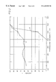
- FIG. 2 is a plot of amount of fuel consumed in a burner that demonstrates workability of the present invention vs. temperature.
- a flameless combustor that can be utilized with improvement, according to the present invention is disclosed in U.S. Pat. No. 5,255,742, the disclosure of which is incorporated herein by reference.
- the improvements of the present invention include three improvements related to the start-up of such a combustor.
- the three improvements may be used individually, but are preferably used in combination with at least two utilized.
- the three improvements of the present invention include: use of the fuel gas conduit as a resistance heater to provide heat for start-up; use of a catalytic surface within the combustion chamber to lower temperatures at which oxidation of the fuel will occur; and use of oxidants other than air, or along with air, to lower autoignition temperatures during start-up.
- An important feature of the flameless combustor of the present invention is that heat is removed along the axis of the combustion chamber so that a temperature is maintained that is significantly below what an adiabatic combustion temperature would be. This almost eliminates formation of NO x s, and also significantly reduces metallurgical requirements resulting in a relatively inexpensive combustor.
- flameless combustion is accomplished by preheating combustion air and fuel gas sufficiently that when the two streams are combined the temperature of the mixture exceeds the autoignition temperature of the mixture, but to a temperature less than that which would result in the oxidation upon mixing being limited by the rate of mixing.
- Preheating of the streams to a temperature between about 1500° F. and about 2300° F. and then mixing the fuel gas into the combustion air in relatively small increments will result in flameless combustion.
- the increments in which the fuel gas is mixed with the combustion gas stream preferably result in about a 20 to 200° F. temperature rise in the combustion gas stream due to the combustion of the fuel.
- a heat injection well and combustor capable of carrying out the present invention are shown.
- a formation to be heated, 1 is below an overburden, 2 .
- a wellbore, 3 extends through the overburden and to a position in or near the bottom of the formation to be heated.
- a vertical well is shown, but the wellbore could be deviated or horizontal.
- Horizontal heat injector wells may be provided in formations that fracture horizontally to recover hydrocarbons by a parallel drive process. Shallow oil shale formations are examples of such formations.
- Horizontal heaters may also effectively be used in thin beds to limit heat loss to overburden and base rock.
- the wellbore is cased with a casing, 4 .
- the lower portion of the wellbore may be cemented with a cement, 7 , having characteristics suitable for withstanding elevated temperatures and transferring heat.
- a cement which is a good thermal insulator, 8 , is preferred for the upper portion of the wellbore to prevent heat loss from the system.
- An oxidant conduit, 10 extends from the wellhead (not shown) to the lower portion of the wellbore.
- a fuel conduit, 12 also extends from the wellhead to the bottom of the wellbore.
- the fuel conduit defines a fuel volume within the fuel conduit. The fuel volume is in communication with a fuel supply, and is in communication with a combustion chamber surrounding the fuel conduit through a plurality of orifices.
- High temperature cements suitable for cementing casing and conduits within the high temperature portions of the wellbore are available. Examples are disclosed in U.S. Pat. Nos. 3,507,332 and 3,180,748. Alumina contents above about 50 percent by weight based on cements slurry solids are preferred.
- the heater In shallow formations, it may be advantageous to hammer-drill the heater directly into the formation.
- cementing of the heater in the formation is may not be required, but an upper portion of the heater may be cemented to prevent fluid loss to the surface.
- Choice of a diameter of the casing, 4 , in the embodiment of FIG. 1 is a trade off between the expense of the casing, and the rate at which heat may be transferred into the formation.
- the casing due to the metallurgy required, is generally the most expensive component of the injection well.
- the heat that can be transferred into the formation increases significantly with increasing casing diameter.
- a casing of between about 4 and about 8 inches in internal diameter will typically provide an optimum trade-off between initial cost and heat transfer.
- the fuel gas conduit contains a plurality of orifices, 13 , (eight shown) along the length of the conduit within the formation to be heated.
- the orifices are separated by an interval distance that is sufficient to allow both significant reaction of the oxidant and fuel between orifices, and removal of heat from the heater along the length of the combustion chamber between the orifices.
- the orifices provide communication between the volume defined by the fuel conduit and the axial combustion chamber.
- a plurality of orifices provide for distribution of heat release within the formation to be heated. Staging release of fuel into the oxidant/combustion product stream results in staged generation of heat, and with uniform transfer of heat from the wellbore as in the embodiment of FIG. 1, temperatures within the wellbore are well below adiabatic combustion temperatures. Avoiding high temperatures significantly reduces metallurgical requirements, and thus cost of the facility. Additionally, temperatures well below adiabatic combustion temperatures avoids creation of NO x s.
- the orifices are sized to accomplish a nearly even temperature distribution within the casing.
- a nearly even temperature profile within the casing results in more uniform heat distribution within the formation to be heated.
- a nearly uniform heat distribution within the formation will result in more efficient utilization of heat in a conductive heating hydrocarbon recovery process.
- a more even temperature profile will also result in lower maximum temperatures for the same heat release. Because the materials of construction of the burner and well system dictate the maximum temperatures, even temperature profiles will increase the heat release possible for the same materials of construction.
- the number of orifices is limited only by size of orifices which are to be used. If more orifices are used, they must generally be of a smaller size. Smaller orifices will plug more easily than larger orifices. The number of orifices is a trade-off between evenness of the temperature profile and the possibility of plugging.
- the number, size, and spacing of the orifices along with the heat removal from the combustion chamber are preferably such that the maximum temperatures within the combustor are less than about 2000° F. This results in long service lives for commercially available materials.
- heat be removed from the combustion chamber between fuel orifices.
- heat is transferred to the formation around the wellbore.
- the heater of the present invention could also be used in other applications, such as steam generation and chemical industry or refinery process heaters.
- air and/or another oxidant could be staged into fuel by providing orifices in the combustion air conduit instead of the fuel conduit.
- Fuel and oxidant transported to bottom of the wellbore combine and react within the wellbore volume surrounding the conduits, 14 , forming combustion products.
- This volume is the axial combustion chamber of the present invention.
- the combustion products travel up the wellbore and out an exhaust vent at the wellhead.
- the combustion products may be treated to remove pollutants, and energy recovery from the combustion products by an expander turbine or heat exchanger may also be desirable.
- An electrical lead 15 can be connected with a clamp 16 or other connection to the fuel line 12 near the wellhead below an electrically insulating coupling to supply electrical energy for initial heating and start-up of the combustor.
- Electrical ground can be provided near the bottom of the borehole with one or more electrically conducting centralizers around the fuel conduit 17 and around the oxidant 18 .
- Centralizers on the fuel conduit above the electrically grounding centralizers are electrically insulating centralizers. Wall thickness of the fuel conduits are preferably decreased in the vicinity of the orifices so that application of electrical energy to the fuel gas conduit results in negligible resistance heating above the orifices, and significant heating below the orifices.
- Sufficient heat is preferably applied to result in fuel exiting the orifices into a flowing oxidant (or air) stream being at or above the autoignition temperature of the fuel-oxidant mixture as the fuel mixes with the oxidant.
- the mixture of fuel and oxidant is above the autoignition temperature of the mixture at these start-up conditions.
- the fuel would ignite when it passes through the orifices and mix with oxidant between orifices.
- Autoignition temperature of the fuel-oxidant mixture is preferably lowered by provision of a catalytic surface 19 in the vicinity of the orifices.
- This catalytic surface is preferably provided on the inside surface of the oxidant conduit 10 .
- the fuel conduit could be provided with such a surface, or a tubular or catalyst containing surface could be separately placed within the oxidant conduit.
- Other catalytic surfaces could be provided, for example in the combustion product annulus outside of the oxidant conduit. This additional catalytic surface could ensure that complete combustion occurred within the wellbore.
- the catalytic surface can also significantly increase the temperature range within which the combustor can operate by decreasing the temperature at which oxidation of the fuel occurs.
- Start-up of the flameless combustor of the present invention can be further enhanced by provision of supplemental oxidants during the start-up phase, and/or by use of a fuel that has a lower catalyzed autoignition temperature such as, for example, hydrogen.
- Preferred oxidants include supplemental oxygen and nitrous oxide.
- Hydrogen could be provided along with a natural gas stream, and could be provided as shift gas, with carbon monoxide present and/or carbon dioxide present. Presence of carbon dioxide would not be preferable, but may be tolerable and removal of some carbon dioxide may not be economically justifiable.
- Acceptable catalyst materials include noble metals, semi-precious metals, and transition metal oxides. Generally, known oxidation catalysts are useful in the present invention. Mixtures of such metals or metal oxides could also be useful.
- Start-up oxidants and/or fuels are preferably only used until the combustor has been heated to a temperature sufficient to enable operation with methane (natural gas) as fuel and air as the oxidant (i.e., the combustor has heated to a temperature above the autoignition temperature of methane in air).
- the preheating of fuel gases such as methane to obtain flameless combustion could result in significant generation of carbon within the fuel conduit unless a carbon formation suppressant is included in the fuel stream.
- the carbon formation suppressant may be carbon dioxide, steam, hydrogen or mixtures thereof. Carbon dioxide and steam are preferred due to the generally higher cost of hydrogen.
- Flameless combustion generally occurs when a reaction between an oxidant stream and a fuel is not limited by mixing and the mixed stream is at a temperature higher than the autoignition temperature of the mixed stream. This is accomplished by avoiding high temperatures at the point of mixing and by mixing relatively small increments of fuel into the oxidant containing stream. The existence of flame is evidenced by an illuminate interface between unburned fuel and the combustion products.
- the fuel and the oxidant are preferably heated to a temperature of between about 1500° F. and about 2300° F. prior to mixing.
- the fuel is preferably mixed with the oxidant stream in relatively small increments to enable more rapid mixing. For example, enough fuel may be added in an increment to enable combustion to raise the temperature of the stream by about 50 to about 100° F.
- the fuel conduit as a resistance heater to provide initial heat for start-up of the flameless combustor of the present invention is a significant improvement because the fuel conduit is present anyway, will generally be made of an electrically conductive material, and being a relatively thick metal, would be expected to be a reliable heater. Thickness of the fuel conduit can be varied to result in release of heat at preselected segments of the length of the fuel conduit. For example, in a well heat injector application, it may be desirable to electrically heat the lowermost portion of the wellbore in order to ensure ignition of the mixed gas stream and guarantee combustion of the fuel, before exhaust gases are passed back up through the wellbore. Electrical energy can be connected to the fuel conduit at the wellhead, and the fuel conduit supported by an insulating hanger, and kept centralized within the air supply conduit with insulating centralizers. The fuel conduit is then grounded below the segment which is to be used as a heater.
- Catalytic metals such as palladium or platinum can be coated, preferably by brush electroplating, onto a surface within the combustion chamber to enhance oxidation of the fuel at lower temperatures.
- Such catalytic surface has been found to be extremely effective in promoting oxidation of methane in air at temperatures as low as 500° F. This reaction rapidly occurs on the catalyst surface, and generally, gases in the boundary layer adjacent to the catalytic surface quickly become fully reacted.
- An advantage of having a significant catalytic surface within the combustion chamber is that the temperature range within which the flameless combustor can operate can be significantly increased.
- a thermal reactor was used to establish temperatures at which oxidation reactions would occur with various combinations of fuels, oxidants and catalyst surfaces.
- the reactor was a one inch stainless steel pipe wrapped with an electrical resistance heating coil, and covered with insulation.
- a thermocouple for temperature control was placed underneath the insulation adjacent to the outer surface of the pipe. Thermocouples were also provided inside the pipe at the inlet, at the middle, and at the outlet. Test ribbons of noble metals or stainless steel strips with noble metal coatings were hung in the pipe to test catalytic activity. Air preheated to a temperature somewhat below the desired temperature of the test was injected into the electrically heated test section of the pipe.
- a ten-foot long test combustor was used to test the results of the one inch reactor in a distributed combustor application.
- a one-inch od. fuel gas line was provided within a two-inch id. combustion line.
- the fuel injection line provided a conduit for fuel to a fuel injection port located near an inlet end of the combustion line.
- the two inch id. combustion line was placed within an insulated pipe, and thermocouple were placed along the fuel supply line.
- Two different combustion lines were utilized.
- One combustion line was fabricated from a strip of “HAYNES 120” alloy. The strip was electro brush plated on one side with palladium to an average thickness of 10 ⁇ 4 inches.
- the strip was then break formed, swedged and welded in to a ten-foot long pipe with the palladium coating on the inside surface.
- the other combustion line was a standard three inch pipe of “HAYNES 120” alloy.
- a “MAXON” burner was used to supply combustion gases to the 10 foot long combustion pipe, and varying amounts of air and/or other additives are mixed with the exhaust from the “MAXON” burner in a mixing section between the burner and the combustion line.
- three electric heaters, each with its own controller, were placed outside and along the length of the combustion line.
Landscapes
- Engineering & Computer Science (AREA)
- Geology (AREA)
- Life Sciences & Earth Sciences (AREA)
- Mining & Mineral Resources (AREA)
- Geochemistry & Mineralogy (AREA)
- Fluid Mechanics (AREA)
- Environmental & Geological Engineering (AREA)
- General Life Sciences & Earth Sciences (AREA)
- Physics & Mathematics (AREA)
- Chemical & Material Sciences (AREA)
- Combustion & Propulsion (AREA)
- Chemical Kinetics & Catalysis (AREA)
- Mechanical Engineering (AREA)
- General Engineering & Computer Science (AREA)
- Physical Or Chemical Processes And Apparatus (AREA)
- Gas Burners (AREA)
- Combustion Of Fluid Fuel (AREA)
- Fluidized-Bed Combustion And Resonant Combustion (AREA)
Abstract
A combustor method and apparatus is provided. The method utilizes flameless combustion with one or more of three improvements to enhance ignition of the flameless combustor. A catalytic surface can be provided within a combustion chamber to provide flameless combustion at least in the vicinity of the catalytic surface at a temperature that is much lower than the autoignition temperature of fuel in air without the presence of the catalytic surface. Nitrous oxide or supplemental oxygen may also be used as an oxidant either instead of air or with air to reduce ignition temperatures. Further, electrical energy can be passed through the fuel conduit, raising the temperature of the conduit to a temperature above which the fuel will ignite when combined with the oxidant.
Description
This application claims benefit to U.S. provisional application serial No. 60/009,435 filed Dec. 27, 1995 and is a division of application Ser. No. 08/774,168 filed Dec. 26, 1996, now U.S. Pat. No. 5,899,269, the entire disclosure of which is hereby incorporated by reference.
This invention relates to a combustor apparatus and method.
U.S. Pat. Nos. 4,640,352 and 4,886,118 disclose conductive heating of subterranean formations of low permeability that contain oil to recover oil therefrom. Low permeability formations include diatomites, lipid coals, tar sands, and oil shales. Formations of low permeability are not amiable to enhanced oil recovery methods such as steam, carbon dioxide, or fire flooding. Flooding materials tend to penetrate formations that have low permeabilities preferentially through fractures. The injected materials bypass most of the formation hydrocarbons. In contrast, conductive heating does not require fluid transport into the formation. Oil within the formation is therefore not bypassed as in a flooding process. When the temperature of a formation is increased by conductive heating, vertical temperature profiles will tend to be relatively uniform because formations generally have relatively uniform thermal conductivities and specific heats. Transportation of hydrocarbons in a thermal conduction process is by pressure drive, vaporization, and thermal expansion of oil and water trapped within the pores of the formation rock. Hydrocarbons migrate through small fractures created by thermal stress and by the expansion and vaporization of the oil and water.
U.S. Pat. Nos. 3,113,623 and 3,181,613 disclose gas fired heat injection burners for heating subterranean formations. These burners utilize porous materials to hold a flame and thereby spreading the flame out over an extended length. Radiant heat transfer from a flame to the casing is avoided by providing the porous medium to hold the flame. But for combustion to take place in the porous medium, the fuel gas and the combustion air must be premixed. If the premixed fuel gas and combustion air were at a temperature above the autoignition temperature of the mixture, they would react upon being premixed instead of within the porous medium. The formations utilized as examples of these inventions are only up to fifty feet thick and below only about fifteen feet of overburden. The fuel gas and the combustion air are therefore relatively cool when they reach the burner. The burner would not function as it was intended if the formation being heated were significantly deeper.
U.S. Pat. No. 5,255,742 discloses a flameless combustor useful for heating subterranean formations that utilizes preheated fuel gas and/or combustion air wherein the fuel gas is combined with the combustion air in increments that are sufficiently small that flames are avoided. Creation of NOx is almost eliminated, and cost of the heaters can be significantly reduced because of less expensive materials of construction. Preheating the fuel gas according to the invention of patent '742 results in coke formation unless CO2, H2, steam, or some other coke suppressant is added to the fuel gas. Further, start-up of the heater of patent '742 is a time consuming process because it must operate at temperatures above the autoignition temperature of the fuel gas mixture. Start-up requires long periods of very low flow-rate operation before temperatures would be sufficiently high for normal operation.
Catalytic combustors are also known. For example, U.S. Pat. No. 3,928,961 discloses a catalytically-supported thermal combustion apparatus wherein formation of NOx is eliminated by combustion at temperatures above auto-ignition temperatures of the fuel, but less than those temperatures at which result in substantial formation of oxides of nitrogen.
Metal surfaces coated with oxidation catalyst are disclosed in, for example, U.S. Pat. Nos. 5,355,668 and 4,065,917. These patents suggest catalytic coated surfaces on components of a gas turbine engine. Patent '917 suggests use of catalytic coated surfaces for start-up of the turbine, and suggests a mass transfer control limited phase in the start-up operation.
It is therefore an object of the present invention to provide a combustion method and apparatus which is flameless, and can be easily ignited and brought up to operating temperatures. In another aspect of the present invention, it is an object to provide a combustion method and apparatus wherein formation of NOx is minimal. It is another object of the present invention to provide a method which has a high level of thermal efficiency.
The method of the present invention utilizes flameless combustion with one or more of three improvements to enhance ignition of the flameless combustor. A catalytic surface can be provided within a combustion chamber to provide flameless combustion at least in the vicinity of the catalytic surface at a temperature that is much lower than the autoignition temperature of fuel in air without the presence of the noble metal surface. Nitrous oxide or supplemental oxygen may also be used as an oxidant either instead of air or with air to further reduce ignition temperatures. Fuels with lower ignition temperatures, for example, hydrogen or hydrogen/carbon monoxide mixture, may also be used to reduce ignition temperatures. Further, electrical energy can be passed through the fuel conduit, raising the temperature of the conduit to a temperature at which the fuel will ignite.
The flameless combustion of the present invention also results in minimal production of nitrous oxides. Other measures to remove or prevent the formation of nitrous oxides are therefore not required.
FIG. 1 shows a combustor suitable for use in the present invention.
FIG. 2 is a plot of amount of fuel consumed in a burner that demonstrates workability of the present invention vs. temperature.
A flameless combustor that can be utilized with improvement, according to the present invention, is disclosed in U.S. Pat. No. 5,255,742, the disclosure of which is incorporated herein by reference. The improvements of the present invention include three improvements related to the start-up of such a combustor. The three improvements may be used individually, but are preferably used in combination with at least two utilized. The three improvements of the present invention include: use of the fuel gas conduit as a resistance heater to provide heat for start-up; use of a catalytic surface within the combustion chamber to lower temperatures at which oxidation of the fuel will occur; and use of oxidants other than air, or along with air, to lower autoignition temperatures during start-up.
An important feature of the flameless combustor of the present invention is that heat is removed along the axis of the combustion chamber so that a temperature is maintained that is significantly below what an adiabatic combustion temperature would be. This almost eliminates formation of NOxs, and also significantly reduces metallurgical requirements resulting in a relatively inexpensive combustor.
Generally, flameless combustion is accomplished by preheating combustion air and fuel gas sufficiently that when the two streams are combined the temperature of the mixture exceeds the autoignition temperature of the mixture, but to a temperature less than that which would result in the oxidation upon mixing being limited by the rate of mixing. Preheating of the streams to a temperature between about 1500° F. and about 2300° F. and then mixing the fuel gas into the combustion air in relatively small increments will result in flameless combustion. The increments in which the fuel gas is mixed with the combustion gas stream preferably result in about a 20 to 200° F. temperature rise in the combustion gas stream due to the combustion of the fuel.
Referring to FIG. 1, a heat injection well and combustor capable of carrying out the present invention are shown. A formation to be heated, 1, is below an overburden, 2. A wellbore, 3, extends through the overburden and to a position in or near the bottom of the formation to be heated. A vertical well is shown, but the wellbore could be deviated or horizontal. Horizontal heat injector wells may be provided in formations that fracture horizontally to recover hydrocarbons by a parallel drive process. Shallow oil shale formations are examples of such formations. Horizontal heaters may also effectively be used in thin beds to limit heat loss to overburden and base rock. In the embodiment shown in FIG. 1, the wellbore is cased with a casing, 4. The lower portion of the wellbore may be cemented with a cement, 7, having characteristics suitable for withstanding elevated temperatures and transferring heat. A cement which is a good thermal insulator, 8, is preferred for the upper portion of the wellbore to prevent heat loss from the system. An oxidant conduit, 10, extends from the wellhead (not shown) to the lower portion of the wellbore. A fuel conduit, 12, also extends from the wellhead to the bottom of the wellbore. The fuel conduit defines a fuel volume within the fuel conduit. The fuel volume is in communication with a fuel supply, and is in communication with a combustion chamber surrounding the fuel conduit through a plurality of orifices.
High temperature cements suitable for cementing casing and conduits within the high temperature portions of the wellbore are available. Examples are disclosed in U.S. Pat. Nos. 3,507,332 and 3,180,748. Alumina contents above about 50 percent by weight based on cements slurry solids are preferred.
In shallow formations, it may be advantageous to hammer-drill the heater directly into the formation. When the heater is hammer-drilled directly into the formation, cementing of the heater in the formation is may not be required, but an upper portion of the heater may be cemented to prevent fluid loss to the surface.
Choice of a diameter of the casing, 4, in the embodiment of FIG. 1 is a trade off between the expense of the casing, and the rate at which heat may be transferred into the formation. The casing, due to the metallurgy required, is generally the most expensive component of the injection well. The heat that can be transferred into the formation increases significantly with increasing casing diameter. A casing of between about 4 and about 8 inches in internal diameter will typically provide an optimum trade-off between initial cost and heat transfer.
The fuel gas conduit contains a plurality of orifices, 13, (eight shown) along the length of the conduit within the formation to be heated. The orifices are separated by an interval distance that is sufficient to allow both significant reaction of the oxidant and fuel between orifices, and removal of heat from the heater along the length of the combustion chamber between the orifices. The orifices provide communication between the volume defined by the fuel conduit and the axial combustion chamber. A plurality of orifices provide for distribution of heat release within the formation to be heated. Staging release of fuel into the oxidant/combustion product stream results in staged generation of heat, and with uniform transfer of heat from the wellbore as in the embodiment of FIG. 1, temperatures within the wellbore are well below adiabatic combustion temperatures. Avoiding high temperatures significantly reduces metallurgical requirements, and thus cost of the facility. Additionally, temperatures well below adiabatic combustion temperatures avoids creation of NOxs.
The orifices are sized to accomplish a nearly even temperature distribution within the casing. A nearly even temperature profile within the casing results in more uniform heat distribution within the formation to be heated. A nearly uniform heat distribution within the formation will result in more efficient utilization of heat in a conductive heating hydrocarbon recovery process. A more even temperature profile will also result in lower maximum temperatures for the same heat release. Because the materials of construction of the burner and well system dictate the maximum temperatures, even temperature profiles will increase the heat release possible for the same materials of construction. The number of orifices is limited only by size of orifices which are to be used. If more orifices are used, they must generally be of a smaller size. Smaller orifices will plug more easily than larger orifices. The number of orifices is a trade-off between evenness of the temperature profile and the possibility of plugging.
The number, size, and spacing of the orifices along with the heat removal from the combustion chamber are preferably such that the maximum temperatures within the combustor are less than about 2000° F. This results in long service lives for commercially available materials.
It is important in the operation of a combustor of the present invention that heat be removed from the combustion chamber between fuel orifices. In the application of the present invention to a wellbore heat injector, heat is transferred to the formation around the wellbore. The heater of the present invention could also be used in other applications, such as steam generation and chemical industry or refinery process heaters.
Alternatively, air and/or another oxidant could be staged into fuel by providing orifices in the combustion air conduit instead of the fuel conduit.
Fuel and oxidant transported to bottom of the wellbore combine and react within the wellbore volume surrounding the conduits, 14, forming combustion products. This volume is the axial combustion chamber of the present invention. The combustion products travel up the wellbore and out an exhaust vent at the wellhead. The combustion products may be treated to remove pollutants, and energy recovery from the combustion products by an expander turbine or heat exchanger may also be desirable.
As the combustion products rise in the wellbore above the formation being heated, heat is exchanged between the oxidant and the fuel traveling down the flow conduits and the combustion products. This heat exchange not only conserves energy, but permits the desirable flameless combustion of the present invention. The fuel and the oxidant are preheated as they travel down the respective flow conduits sufficiently that the mixture of the two streams at the ultimate mixing point is at a temperature above the autoignition temperature of the mixture. Flameless combustion results, avoiding a flame as a radiant heat source. Heat is therefore transferred from the wellbore in an essentially uniform fashion.
An electrical lead 15 can be connected with a clamp 16 or other connection to the fuel line 12 near the wellhead below an electrically insulating coupling to supply electrical energy for initial heating and start-up of the combustor. Electrical ground can be provided near the bottom of the borehole with one or more electrically conducting centralizers around the fuel conduit 17 and around the oxidant 18. Centralizers on the fuel conduit above the electrically grounding centralizers are electrically insulating centralizers. Wall thickness of the fuel conduits are preferably decreased in the vicinity of the orifices so that application of electrical energy to the fuel gas conduit results in negligible resistance heating above the orifices, and significant heating below the orifices. Sufficient heat is preferably applied to result in fuel exiting the orifices into a flowing oxidant (or air) stream being at or above the autoignition temperature of the fuel-oxidant mixture as the fuel mixes with the oxidant. Most preferably, the mixture of fuel and oxidant is above the autoignition temperature of the mixture at these start-up conditions. Thus, the fuel would ignite when it passes through the orifices and mix with oxidant between orifices.
Autoignition temperature of the fuel-oxidant mixture is preferably lowered by provision of a catalytic surface 19 in the vicinity of the orifices. This catalytic surface is preferably provided on the inside surface of the oxidant conduit 10. Alternatively, either the fuel conduit could be provided with such a surface, or a tubular or catalyst containing surface could be separately placed within the oxidant conduit. Other catalytic surfaces could be provided, for example in the combustion product annulus outside of the oxidant conduit. This additional catalytic surface could ensure that complete combustion occurred within the wellbore. The catalytic surface can also significantly increase the temperature range within which the combustor can operate by decreasing the temperature at which oxidation of the fuel occurs.
Start-up of the flameless combustor of the present invention can be further enhanced by provision of supplemental oxidants during the start-up phase, and/or by use of a fuel that has a lower catalyzed autoignition temperature such as, for example, hydrogen. Preferred oxidants include supplemental oxygen and nitrous oxide. Hydrogen could be provided along with a natural gas stream, and could be provided as shift gas, with carbon monoxide present and/or carbon dioxide present. Presence of carbon dioxide would not be preferable, but may be tolerable and removal of some carbon dioxide may not be economically justifiable.
Acceptable catalyst materials include noble metals, semi-precious metals, and transition metal oxides. Generally, known oxidation catalysts are useful in the present invention. Mixtures of such metals or metal oxides could also be useful.
Start-up oxidants and/or fuels are preferably only used until the combustor has been heated to a temperature sufficient to enable operation with methane (natural gas) as fuel and air as the oxidant (i.e., the combustor has heated to a temperature above the autoignition temperature of methane in air).
The preheating of fuel gases such as methane to obtain flameless combustion could result in significant generation of carbon within the fuel conduit unless a carbon formation suppressant is included in the fuel stream. The carbon formation suppressant may be carbon dioxide, steam, hydrogen or mixtures thereof. Carbon dioxide and steam are preferred due to the generally higher cost of hydrogen.
Flameless combustion generally occurs when a reaction between an oxidant stream and a fuel is not limited by mixing and the mixed stream is at a temperature higher than the autoignition temperature of the mixed stream. This is accomplished by avoiding high temperatures at the point of mixing and by mixing relatively small increments of fuel into the oxidant containing stream. The existence of flame is evidenced by an illuminate interface between unburned fuel and the combustion products. To avoid the creation of a flame, the fuel and the oxidant are preferably heated to a temperature of between about 1500° F. and about 2300° F. prior to mixing. The fuel is preferably mixed with the oxidant stream in relatively small increments to enable more rapid mixing. For example, enough fuel may be added in an increment to enable combustion to raise the temperature of the stream by about 50 to about 100° F.
Use of the fuel conduit as a resistance heater to provide initial heat for start-up of the flameless combustor of the present invention is a significant improvement because the fuel conduit is present anyway, will generally be made of an electrically conductive material, and being a relatively thick metal, would be expected to be a reliable heater. Thickness of the fuel conduit can be varied to result in release of heat at preselected segments of the length of the fuel conduit. For example, in a well heat injector application, it may be desirable to electrically heat the lowermost portion of the wellbore in order to ensure ignition of the mixed gas stream and guarantee combustion of the fuel, before exhaust gases are passed back up through the wellbore. Electrical energy can be connected to the fuel conduit at the wellhead, and the fuel conduit supported by an insulating hanger, and kept centralized within the air supply conduit with insulating centralizers. The fuel conduit is then grounded below the segment which is to be used as a heater.
Catalytic metals such as palladium or platinum can be coated, preferably by brush electroplating, onto a surface within the combustion chamber to enhance oxidation of the fuel at lower temperatures. Such catalytic surface has been found to be extremely effective in promoting oxidation of methane in air at temperatures as low as 500° F. This reaction rapidly occurs on the catalyst surface, and generally, gases in the boundary layer adjacent to the catalytic surface quickly become fully reacted. An advantage of having a significant catalytic surface within the combustion chamber is that the temperature range within which the flameless combustor can operate can be significantly increased.
A thermal reactor was used to establish temperatures at which oxidation reactions would occur with various combinations of fuels, oxidants and catalyst surfaces. The reactor was a one inch stainless steel pipe wrapped with an electrical resistance heating coil, and covered with insulation. A thermocouple for temperature control was placed underneath the insulation adjacent to the outer surface of the pipe. Thermocouples were also provided inside the pipe at the inlet, at the middle, and at the outlet. Test ribbons of noble metals or stainless steel strips with noble metal coatings were hung in the pipe to test catalytic activity. Air preheated to a temperature somewhat below the desired temperature of the test was injected into the electrically heated test section of the pipe. Electrical power to the electrical resistance heater was varied until the desired temperature in the test section was obtained and a steady state, as measured by the thermocouples mounted inside the pipe, was achieved. Fuel was then injected through a mixing tee into the stream of preheated air and allowed to flow into the electrically heated test section. Four platinum ribbons one eighth of an inch wide and about sixteen inches long or a stainless steal strip three eighths of an inch wide and about one sixteenth of an inch thick and about sixteen inches long coated on both sides with either platinum or palladium were suspended within the pipe to test catalytic activity. When the test section contained a catalyst coated strep or ribbon of noble metal and was at or above the catalyzed autoignition temperature, the addition of fuel caused a temperature increase at the inside middle and outlet thermocouples. Below the catalyzed autoignition temperature, such a temperature was not observed. When no catalytic coated strips or noble metal ribbons were present, the test section had to be heated to the autoignition temperature of the fuel before a temperature increase was observed. The non-catalyzed and catalyzed autoignition temperatures as measured are summarized in the TABLE, with the measured non-catalyzed or catalyzed autoignition temperature referred to as the measured autoignition temperature.
| TABLE | |||||
| MEASURED | FUEL | ||||
| AUTO- | AIR FLOW | CONC. | ACCEL. | ||
| IGNITION | RATE | % OF AIR | % OF AIR | ||
| FUEL | TEMP. ° F. | CC/MIN | VOL. % | VOL % | CATALYST |
| NAT. GAS | 1450 | 380 | 10.5 | ||
| NAT. GAS | 1350 | 380 | 2.6 | N2O/21 | |
| NAT. GAS | 1251 | 380 | 2.6 | O2/40 | |
| DIMETHYL | 950 | 380 | 2.6 | ||
| ETHER | |||||
| DIMETHYL | 601 | 380 | 2.6 | N2O/21 | |
| ETHER | |||||
| H2 | 1218 | 380 | 13 | ||
| H2 | 120 | 380 | 13 | Pt | |
| 66.6% H2 | 1249 | 380 | 13 | ||
| 33.3% CO | |||||
| 66.6% H2 | 416 | 380 | 13 | ||
| 33.3% CO | |||||
| 66.6% H2 | 411 | 380 | 13 | N2O/44.7 | Pt |
| 33.3% CO | |||||
| 66.6% H2 | 300 | 0 | 13 | 380 CC/MIN | Pt |
| 33.3 |
100% N2O | ||||
| Methane | 590 | 380 | 13 | — | Pd |
| H2 | 300 | 380 | 13 | — | Pd |
| 66.6% H2 | 310 | 380 | 13 | — | Pd |
| 33.3% CO | |||||
From the TABLE it can be seen that addition of N2O to the fuel stream greatly reduces the measured autoignition temperature of the mixtures. Further, inclusion of hydrogen as a fuel and presence of the catalytic surface also significantly reduces the dynamic autoignition temperatures.
A ten-foot long test combustor was used to test the results of the one inch reactor in a distributed combustor application. A one-inch od. fuel gas line was provided within a two-inch id. combustion line. The fuel injection line provided a conduit for fuel to a fuel injection port located near an inlet end of the combustion line. The two inch id. combustion line was placed within an insulated pipe, and thermocouple were placed along the fuel supply line. Two different combustion lines were utilized. One combustion line was fabricated from a strip of “HAYNES 120” alloy. The strip was electro brush plated on one side with palladium to an average thickness of 10−4 inches. The strip was then break formed, swedged and welded in to a ten-foot long pipe with the palladium coating on the inside surface. The other combustion line was a standard three inch pipe of “HAYNES 120” alloy. A “MAXON” burner was used to supply combustion gases to the 10 foot long combustion pipe, and varying amounts of air and/or other additives are mixed with the exhaust from the “MAXON” burner in a mixing section between the burner and the combustion line. To maintain a uniform temperature within the combustion line, three electric heaters, each with its own controller, were placed outside and along the length of the combustion line.
A series of tests were run, one with the palladium coated combustion line and one with the combustion line that was not palladium coated. Fuel gas was injected through the fuel gas injection port at a rate of 0.374 SCFM, and 220 SCFM of air was injected, including the burner air and the secondary air. Enough fuel gas was provided to the burner to provide a target temperature at the inlet of the combustion line. Percentage of the injected methane that was burned is shown as a function of the combustion line inlet temperature in FIG. 2 for catalyzed configuration (line A) and noncatalyzed configuration (line B). From FIG. 2 it can be seen that at the lowest temperatures at which the apparatus can be operated is about 500° F., 55% of the methane was oxidized with the palladium coated combustion line. The lowest temperature of operation might be somewhat below 500° F. but the equipment available was not capable of operation at lower temperature. When the combustion line without the palladium coating was used, some oxidation of methane occurred at 1300° F., and oxidation of methane occurs rapidly at temperatures of about 1500° F. At temperatures of 1600° F. and above, the presence of the palladium surface has no effect because oxidation of methane is rapid and complete either with or without the palladium surface.
The temperature independence of the methane oxidized below 1300° F. tends to verify that the methane within the boundary layer at the surface of the palladium surface oxidizes rapidly, and that transportation of methane to this boundary layer, and not kinetics, dictates the extent to which methane is oxidized. At temperatures of about 1300° F. and greater, thermal oxidation becomes prevalent, and a temperature dependence is due to this thermal oxidation.
Claims (5)
1. A method to ignite a flameless combustor comprising:
providing an axial combustion chamber in communication with an inlet for oxidant at one end and in communication with a combustion product outlet at the other end;
providing a fuel conduit within the axial combustion chamber, the fuel conduit defining a fuel volume, the fuel volume in communication with a fuel supply, and in communication with the combustion chamber through a plurality of orifices located along the fuel conduit;
passing an oxidant selected from the group consisting of nitrous oxide and supplemental oxygen to the combustion chamber;
passing a stream of fuel to the fuel volume;
heating the stream of fuel, oxidant, or both the stream of fuel and oxidant to a temperature that results in reaction of the oxidant and the fuel when fuel combines with the oxidant;
continuing to pass the oxidant to the combustion chamber and fuel to the fuel conduit until the temperature within the combustion chamber exceeds an autoignition temperature of the fuel in air; and
replacing the oxidant with air after the temperature within the combustion chamber exceeds the autoignition temperature of the fuel in air.
2. The method of claim 1 further comprising the step of passing an amount of electricity through the fuel conduit sufficient to cause the fuel conduit, for at least a portion of the conduit in the vicinity of at least one orifice, to heat to a temperature of at least 1300° F.
3. The method of claim 1 further comprising the step of providing a catalytic surface within the combustion chamber, the catalytic surface effective to reduce the autoignition temperature at which the fuel and oxidant react in the vicinity of the catalytic surface.
4. The method of claim 1 wherein the fuel is hydrogen.
5. The method of claim 1 wherein the fuel comprises hydrogen and carbon monoxide.
Priority Applications (1)
| Application Number | Priority Date | Filing Date | Title |
|---|---|---|---|
| US09/233,300 US6269882B1 (en) | 1995-12-27 | 1999-01-19 | Method for ignition of flameless combustor |
Applications Claiming Priority (3)
| Application Number | Priority Date | Filing Date | Title |
|---|---|---|---|
| US934595P | 1995-12-27 | 1995-12-27 | |
| US08/774,168 US5899269A (en) | 1995-12-27 | 1996-12-26 | Flameless combustor |
| US09/233,300 US6269882B1 (en) | 1995-12-27 | 1999-01-19 | Method for ignition of flameless combustor |
Related Parent Applications (1)
| Application Number | Title | Priority Date | Filing Date |
|---|---|---|---|
| US08/774,168 Division US5899269A (en) | 1995-12-27 | 1996-12-26 | Flameless combustor |
Publications (1)
| Publication Number | Publication Date |
|---|---|
| US6269882B1 true US6269882B1 (en) | 2001-08-07 |
Family
ID=21737075
Family Applications (3)
| Application Number | Title | Priority Date | Filing Date |
|---|---|---|---|
| US08/774,168 Expired - Lifetime US5899269A (en) | 1995-12-27 | 1996-12-26 | Flameless combustor |
| US09/233,301 Expired - Lifetime US6019172A (en) | 1995-12-27 | 1999-01-19 | Flameless combustor |
| US09/233,300 Expired - Lifetime US6269882B1 (en) | 1995-12-27 | 1999-01-19 | Method for ignition of flameless combustor |
Family Applications Before (2)
| Application Number | Title | Priority Date | Filing Date |
|---|---|---|---|
| US08/774,168 Expired - Lifetime US5899269A (en) | 1995-12-27 | 1996-12-26 | Flameless combustor |
| US09/233,301 Expired - Lifetime US6019172A (en) | 1995-12-27 | 1999-01-19 | Flameless combustor |
Country Status (21)
| Country | Link |
|---|---|
| US (3) | US5899269A (en) |
| EP (1) | EP0870100B1 (en) |
| JP (1) | JP3747066B2 (en) |
| KR (1) | KR100445853B1 (en) |
| CN (1) | CN1079885C (en) |
| AT (1) | ATE191254T1 (en) |
| AU (1) | AU696743B2 (en) |
| BR (1) | BR9612363A (en) |
| CA (1) | CA2240411C (en) |
| DE (1) | DE69607485T2 (en) |
| DK (1) | DK0870100T3 (en) |
| EA (1) | EA000249B1 (en) |
| EG (1) | EG21060A (en) |
| ES (1) | ES2145513T3 (en) |
| GR (1) | GR3033618T3 (en) |
| IL (1) | IL124806A (en) |
| JO (1) | JO1948B1 (en) |
| MA (1) | MA24040A1 (en) |
| PT (1) | PT870100E (en) |
| TR (2) | TR199900452T2 (en) |
| WO (1) | WO1997024509A1 (en) |
Cited By (117)
| Publication number | Priority date | Publication date | Assignee | Title |
|---|---|---|---|---|
| US6796789B1 (en) | 2003-01-14 | 2004-09-28 | Petro-Chem Development Co. Inc. | Method to facilitate flameless combustion absent catalyst or high temperature oxident |
| WO2005038347A2 (en) * | 2003-10-10 | 2005-04-28 | Bacon David W | Apparatus for igniting combustible mediums |
| US20050277074A1 (en) * | 2004-06-10 | 2005-12-15 | Zinn Ben T | Stagnation point reverse flow combustor |
| US20060029894A1 (en) * | 2004-06-10 | 2006-02-09 | Zinn Ben T | Stagnation point reverse flow combustor for a combustion system |
| US20060201668A1 (en) * | 2005-03-09 | 2006-09-14 | 391854 Alberta Ltd. | Heat exchanging apparatus |
| US20060210468A1 (en) * | 2005-03-10 | 2006-09-21 | Peter Veenstra | Heat transfer system for the combustion of a fuel and heating of a process fluid and a process that uses same |
| US20060222578A1 (en) * | 2005-03-10 | 2006-10-05 | Peter Veenstra | Method of starting up a direct heating system for the flameless combustion of fuel and direct heating of a process fluid |
| US20070022758A1 (en) * | 2005-06-30 | 2007-02-01 | General Electric Company | Reverse-flow gas turbine combustion system |
| US20070154855A1 (en) * | 2006-01-05 | 2007-07-05 | Great Southern Flameless, Llc | System, apparatus and method for flameless combustion absent catalyst or high temperature oxidants |
| US20080078581A1 (en) * | 2006-09-18 | 2008-04-03 | Schlumberger Technology Corporation | Method and Apparatus for Sampling High Viscosity Formation Fluids |
| US20080090188A1 (en) * | 2006-10-12 | 2008-04-17 | Pisklak Thomas J | Catalytic Burner |
| US20080217008A1 (en) * | 2006-10-09 | 2008-09-11 | Langdon John E | Process for dispersing nanocatalysts into petroleum-bearing formations |
| US20080241774A1 (en) * | 2007-03-30 | 2008-10-02 | Pierangelo Ghilardi | Compact apparatus for generating a hot air flow with a gas burner |
| US20090056696A1 (en) * | 2007-07-20 | 2009-03-05 | Abdul Wahid Munshi | Flameless combustion heater |
| US20090136879A1 (en) * | 2007-07-20 | 2009-05-28 | Karl Gregory Anderson | Flameless combustion heater |
| US20090200016A1 (en) * | 2006-09-18 | 2009-08-13 | Goodwin Anthony R H | Method and apparatus to facilitate formation sampling |
| US20090272532A1 (en) * | 2008-04-30 | 2009-11-05 | Kuhlman Myron I | Method for increasing the recovery of hydrocarbons |
| US20090314077A1 (en) * | 2005-10-26 | 2009-12-24 | Schlumberger Technology Corporation | Downhole sampling apparatus and method for using same |
| US7770646B2 (en) | 2006-10-09 | 2010-08-10 | World Energy Systems, Inc. | System, method and apparatus for hydrogen-oxygen burner in downhole steam generator |
| US20110127036A1 (en) * | 2009-07-17 | 2011-06-02 | Daniel Tilmont | Method and apparatus for a downhole gas generator |
| WO2011130612A2 (en) * | 2010-04-15 | 2011-10-20 | Thomas Merritt | System and method for the generation of hydrogen fuel product |
| US8162052B2 (en) | 2008-01-23 | 2012-04-24 | Schlumberger Technology Corporation | Formation tester with low flowline volume and method of use thereof |
| US8393160B2 (en) | 2007-10-23 | 2013-03-12 | Flex Power Generation, Inc. | Managing leaks in a gas turbine system |
| US8613316B2 (en) | 2010-03-08 | 2013-12-24 | World Energy Systems Incorporated | Downhole steam generator and method of use |
| US8621869B2 (en) | 2009-05-01 | 2014-01-07 | Ener-Core Power, Inc. | Heating a reaction chamber |
| US8671917B2 (en) | 2012-03-09 | 2014-03-18 | Ener-Core Power, Inc. | Gradual oxidation with reciprocating engine |
| US8671658B2 (en) | 2007-10-23 | 2014-03-18 | Ener-Core Power, Inc. | Oxidizing fuel |
| US8701413B2 (en) | 2008-12-08 | 2014-04-22 | Ener-Core Power, Inc. | Oxidizing fuel in multiple operating modes |
| US8734545B2 (en) | 2008-03-28 | 2014-05-27 | Exxonmobil Upstream Research Company | Low emission power generation and hydrocarbon recovery systems and methods |
| US8807989B2 (en) | 2012-03-09 | 2014-08-19 | Ener-Core Power, Inc. | Staged gradual oxidation |
| US8844473B2 (en) | 2012-03-09 | 2014-09-30 | Ener-Core Power, Inc. | Gradual oxidation with reciprocating engine |
| US8893468B2 (en) | 2010-03-15 | 2014-11-25 | Ener-Core Power, Inc. | Processing fuel and water |
| US8926917B2 (en) | 2012-03-09 | 2015-01-06 | Ener-Core Power, Inc. | Gradual oxidation with adiabatic temperature above flameout temperature |
| US8980193B2 (en) | 2012-03-09 | 2015-03-17 | Ener-Core Power, Inc. | Gradual oxidation and multiple flow paths |
| US8980192B2 (en) | 2012-03-09 | 2015-03-17 | Ener-Core Power, Inc. | Gradual oxidation below flameout temperature |
| US8984857B2 (en) | 2008-03-28 | 2015-03-24 | Exxonmobil Upstream Research Company | Low emission power generation and hydrocarbon recovery systems and methods |
| US9017618B2 (en) | 2012-03-09 | 2015-04-28 | Ener-Core Power, Inc. | Gradual oxidation with heat exchange media |
| US9027321B2 (en) | 2008-03-28 | 2015-05-12 | Exxonmobil Upstream Research Company | Low emission power generation and hydrocarbon recovery systems and methods |
| US9057028B2 (en) | 2011-05-25 | 2015-06-16 | Ener-Core Power, Inc. | Gasifier power plant and management of wastes |
| US9206980B2 (en) | 2012-03-09 | 2015-12-08 | Ener-Core Power, Inc. | Gradual oxidation and autoignition temperature controls |
| US9222671B2 (en) | 2008-10-14 | 2015-12-29 | Exxonmobil Upstream Research Company | Methods and systems for controlling the products of combustion |
| US9234660B2 (en) | 2012-03-09 | 2016-01-12 | Ener-Core Power, Inc. | Gradual oxidation with heat transfer |
| US9267432B2 (en) | 2012-03-09 | 2016-02-23 | Ener-Core Power, Inc. | Staged gradual oxidation |
| US9273608B2 (en) | 2012-03-09 | 2016-03-01 | Ener-Core Power, Inc. | Gradual oxidation and autoignition temperature controls |
| US9273606B2 (en) | 2011-11-04 | 2016-03-01 | Ener-Core Power, Inc. | Controls for multi-combustor turbine |
| US9279364B2 (en) | 2011-11-04 | 2016-03-08 | Ener-Core Power, Inc. | Multi-combustor turbine |
| US9291027B2 (en) | 2013-01-25 | 2016-03-22 | Schlumberger Technology Corporation | Packer and packer outer layer |
| US9328660B2 (en) | 2012-03-09 | 2016-05-03 | Ener-Core Power, Inc. | Gradual oxidation and multiple flow paths |
| US9328916B2 (en) | 2012-03-09 | 2016-05-03 | Ener-Core Power, Inc. | Gradual oxidation with heat control |
| US9347664B2 (en) | 2012-03-09 | 2016-05-24 | Ener-Core Power, Inc. | Gradual oxidation with heat control |
| US9353682B2 (en) | 2012-04-12 | 2016-05-31 | General Electric Company | Methods, systems and apparatus relating to combustion turbine power plants with exhaust gas recirculation |
| US9353946B2 (en) | 2012-03-09 | 2016-05-31 | Ener-Core Power, Inc. | Gradual oxidation with heat transfer |
| US9359948B2 (en) | 2012-03-09 | 2016-06-07 | Ener-Core Power, Inc. | Gradual oxidation with heat control |
| US9359947B2 (en) | 2012-03-09 | 2016-06-07 | Ener-Core Power, Inc. | Gradual oxidation with heat control |
| US9371993B2 (en) | 2012-03-09 | 2016-06-21 | Ener-Core Power, Inc. | Gradual oxidation below flameout temperature |
| US9381484B2 (en) | 2012-03-09 | 2016-07-05 | Ener-Core Power, Inc. | Gradual oxidation with adiabatic temperature above flameout temperature |
| CN105840162A (en) * | 2016-05-17 | 2016-08-10 | 赵金岷 | Underground combustion convection heating method |
| US9463417B2 (en) | 2011-03-22 | 2016-10-11 | Exxonmobil Upstream Research Company | Low emission power generation systems and methods incorporating carbon dioxide separation |
| US9512759B2 (en) | 2013-02-06 | 2016-12-06 | General Electric Company | System and method for catalyst heat utilization for gas turbine with exhaust gas recirculation |
| US9534780B2 (en) | 2012-03-09 | 2017-01-03 | Ener-Core Power, Inc. | Hybrid gradual oxidation |
| US9567903B2 (en) | 2012-03-09 | 2017-02-14 | Ener-Core Power, Inc. | Gradual oxidation with heat transfer |
| US9574496B2 (en) | 2012-12-28 | 2017-02-21 | General Electric Company | System and method for a turbine combustor |
| US9581081B2 (en) | 2013-01-13 | 2017-02-28 | General Electric Company | System and method for protecting components in a gas turbine engine with exhaust gas recirculation |
| US9587510B2 (en) | 2013-07-30 | 2017-03-07 | General Electric Company | System and method for a gas turbine engine sensor |
| US9599021B2 (en) | 2011-03-22 | 2017-03-21 | Exxonmobil Upstream Research Company | Systems and methods for controlling stoichiometric combustion in low emission turbine systems |
| US9599070B2 (en) | 2012-11-02 | 2017-03-21 | General Electric Company | System and method for oxidant compression in a stoichiometric exhaust gas recirculation gas turbine system |
| US9611756B2 (en) | 2012-11-02 | 2017-04-04 | General Electric Company | System and method for protecting components in a gas turbine engine with exhaust gas recirculation |
| US9618261B2 (en) | 2013-03-08 | 2017-04-11 | Exxonmobil Upstream Research Company | Power generation and LNG production |
| US9617914B2 (en) | 2013-06-28 | 2017-04-11 | General Electric Company | Systems and methods for monitoring gas turbine systems having exhaust gas recirculation |
| US9631542B2 (en) | 2013-06-28 | 2017-04-25 | General Electric Company | System and method for exhausting combustion gases from gas turbine engines |
| US9631815B2 (en) | 2012-12-28 | 2017-04-25 | General Electric Company | System and method for a turbine combustor |
| US9670841B2 (en) | 2011-03-22 | 2017-06-06 | Exxonmobil Upstream Research Company | Methods of varying low emission turbine gas recycle circuits and systems and apparatus related thereto |
| US9689309B2 (en) | 2011-03-22 | 2017-06-27 | Exxonmobil Upstream Research Company | Systems and methods for carbon dioxide capture in low emission combined turbine systems |
| US9708977B2 (en) | 2012-12-28 | 2017-07-18 | General Electric Company | System and method for reheat in gas turbine with exhaust gas recirculation |
| US9726374B2 (en) | 2012-03-09 | 2017-08-08 | Ener-Core Power, Inc. | Gradual oxidation with flue gas |
| US9732673B2 (en) | 2010-07-02 | 2017-08-15 | Exxonmobil Upstream Research Company | Stoichiometric combustion with exhaust gas recirculation and direct contact cooler |
| US9732675B2 (en) | 2010-07-02 | 2017-08-15 | Exxonmobil Upstream Research Company | Low emission power generation systems and methods |
| US9752458B2 (en) | 2013-12-04 | 2017-09-05 | General Electric Company | System and method for a gas turbine engine |
| US9784185B2 (en) | 2012-04-26 | 2017-10-10 | General Electric Company | System and method for cooling a gas turbine with an exhaust gas provided by the gas turbine |
| US9784140B2 (en) | 2013-03-08 | 2017-10-10 | Exxonmobil Upstream Research Company | Processing exhaust for use in enhanced oil recovery |
| US9784182B2 (en) | 2013-03-08 | 2017-10-10 | Exxonmobil Upstream Research Company | Power generation and methane recovery from methane hydrates |
| US9803865B2 (en) | 2012-12-28 | 2017-10-31 | General Electric Company | System and method for a turbine combustor |
| US9810050B2 (en) | 2011-12-20 | 2017-11-07 | Exxonmobil Upstream Research Company | Enhanced coal-bed methane production |
| US9819292B2 (en) | 2014-12-31 | 2017-11-14 | General Electric Company | Systems and methods to respond to grid overfrequency events for a stoichiometric exhaust recirculation gas turbine |
| US9835089B2 (en) | 2013-06-28 | 2017-12-05 | General Electric Company | System and method for a fuel nozzle |
| US9863267B2 (en) | 2014-01-21 | 2018-01-09 | General Electric Company | System and method of control for a gas turbine engine |
| US9869279B2 (en) | 2012-11-02 | 2018-01-16 | General Electric Company | System and method for a multi-wall turbine combustor |
| US9869247B2 (en) | 2014-12-31 | 2018-01-16 | General Electric Company | Systems and methods of estimating a combustion equivalence ratio in a gas turbine with exhaust gas recirculation |
| US9885290B2 (en) | 2014-06-30 | 2018-02-06 | General Electric Company | Erosion suppression system and method in an exhaust gas recirculation gas turbine system |
| US9903271B2 (en) | 2010-07-02 | 2018-02-27 | Exxonmobil Upstream Research Company | Low emission triple-cycle power generation and CO2 separation systems and methods |
| US9903588B2 (en) | 2013-07-30 | 2018-02-27 | General Electric Company | System and method for barrier in passage of combustor of gas turbine engine with exhaust gas recirculation |
| US9903316B2 (en) | 2010-07-02 | 2018-02-27 | Exxonmobil Upstream Research Company | Stoichiometric combustion of enriched air with exhaust gas recirculation |
| US9915200B2 (en) | 2014-01-21 | 2018-03-13 | General Electric Company | System and method for controlling the combustion process in a gas turbine operating with exhaust gas recirculation |
| US9932874B2 (en) | 2013-02-21 | 2018-04-03 | Exxonmobil Upstream Research Company | Reducing oxygen in a gas turbine exhaust |
| US9938861B2 (en) | 2013-02-21 | 2018-04-10 | Exxonmobil Upstream Research Company | Fuel combusting method |
| US9951658B2 (en) | 2013-07-31 | 2018-04-24 | General Electric Company | System and method for an oxidant heating system |
| US10012151B2 (en) | 2013-06-28 | 2018-07-03 | General Electric Company | Systems and methods for controlling exhaust gas flow in exhaust gas recirculation gas turbine systems |
| US10030588B2 (en) | 2013-12-04 | 2018-07-24 | General Electric Company | Gas turbine combustor diagnostic system and method |
| US10047633B2 (en) | 2014-05-16 | 2018-08-14 | General Electric Company | Bearing housing |
| US10060359B2 (en) | 2014-06-30 | 2018-08-28 | General Electric Company | Method and system for combustion control for gas turbine system with exhaust gas recirculation |
| US10079564B2 (en) | 2014-01-27 | 2018-09-18 | General Electric Company | System and method for a stoichiometric exhaust gas recirculation gas turbine system |
| US10094566B2 (en) | 2015-02-04 | 2018-10-09 | General Electric Company | Systems and methods for high volumetric oxidant flow in gas turbine engine with exhaust gas recirculation |
| US10100741B2 (en) | 2012-11-02 | 2018-10-16 | General Electric Company | System and method for diffusion combustion with oxidant-diluent mixing in a stoichiometric exhaust gas recirculation gas turbine system |
| US10107495B2 (en) | 2012-11-02 | 2018-10-23 | General Electric Company | Gas turbine combustor control system for stoichiometric combustion in the presence of a diluent |
| US10145269B2 (en) | 2015-03-04 | 2018-12-04 | General Electric Company | System and method for cooling discharge flow |
| US10208677B2 (en) | 2012-12-31 | 2019-02-19 | General Electric Company | Gas turbine load control system |
| US10215412B2 (en) | 2012-11-02 | 2019-02-26 | General Electric Company | System and method for load control with diffusion combustion in a stoichiometric exhaust gas recirculation gas turbine system |
| US10221762B2 (en) | 2013-02-28 | 2019-03-05 | General Electric Company | System and method for a turbine combustor |
| US10227920B2 (en) | 2014-01-15 | 2019-03-12 | General Electric Company | Gas turbine oxidant separation system |
| US10253690B2 (en) | 2015-02-04 | 2019-04-09 | General Electric Company | Turbine system with exhaust gas recirculation, separation and extraction |
| US10267270B2 (en) | 2015-02-06 | 2019-04-23 | General Electric Company | Systems and methods for carbon black production with a gas turbine engine having exhaust gas recirculation |
| US10273880B2 (en) | 2012-04-26 | 2019-04-30 | General Electric Company | System and method of recirculating exhaust gas for use in a plurality of flow paths in a gas turbine engine |
| US10315150B2 (en) | 2013-03-08 | 2019-06-11 | Exxonmobil Upstream Research Company | Carbon dioxide recovery |
| US10316746B2 (en) | 2015-02-04 | 2019-06-11 | General Electric Company | Turbine system with exhaust gas recirculation, separation and extraction |
| US10480792B2 (en) | 2015-03-06 | 2019-11-19 | General Electric Company | Fuel staging in a gas turbine engine |
| US10655542B2 (en) | 2014-06-30 | 2020-05-19 | General Electric Company | Method and system for startup of gas turbine system drive trains with exhaust gas recirculation |
| US10788212B2 (en) | 2015-01-12 | 2020-09-29 | General Electric Company | System and method for an oxidant passageway in a gas turbine system with exhaust gas recirculation |
Families Citing this family (100)
| Publication number | Priority date | Publication date | Assignee | Title |
|---|---|---|---|---|
| ATE191254T1 (en) * | 1995-12-27 | 2000-04-15 | Shell Int Research | FLAMELESS COMBUSTION APPARATUS AND METHOD |
| US5985222A (en) * | 1996-11-01 | 1999-11-16 | Noxtech, Inc. | Apparatus and method for reducing NOx from exhaust gases produced by industrial processes |
| US6715548B2 (en) | 2000-04-24 | 2004-04-06 | Shell Oil Company | In situ thermal processing of a hydrocarbon containing formation to produce nitrogen containing formation fluids |
| US6588503B2 (en) | 2000-04-24 | 2003-07-08 | Shell Oil Company | In Situ thermal processing of a coal formation to control product composition |
| US7011154B2 (en) * | 2000-04-24 | 2006-03-14 | Shell Oil Company | In situ recovery from a kerogen and liquid hydrocarbon containing formation |
| US6698515B2 (en) | 2000-04-24 | 2004-03-02 | Shell Oil Company | In situ thermal processing of a coal formation using a relatively slow heating rate |
| US6715546B2 (en) | 2000-04-24 | 2004-04-06 | Shell Oil Company | In situ production of synthesis gas from a hydrocarbon containing formation through a heat source wellbore |
| US6588504B2 (en) | 2000-04-24 | 2003-07-08 | Shell Oil Company | In situ thermal processing of a coal formation to produce nitrogen and/or sulfur containing formation fluids |
| US20030146002A1 (en) * | 2001-04-24 | 2003-08-07 | Vinegar Harold J. | Removable heat sources for in situ thermal processing of an oil shale formation |
| WO2003036033A1 (en) | 2001-10-24 | 2003-05-01 | Shell Internationale Research Maatschappij B.V. | Simulation of in situ recovery from a hydrocarbon containing formation |
| US7090013B2 (en) * | 2001-10-24 | 2006-08-15 | Shell Oil Company | In situ thermal processing of a hydrocarbon containing formation to produce heated fluids |
| US7104319B2 (en) * | 2001-10-24 | 2006-09-12 | Shell Oil Company | In situ thermal processing of a heavy oil diatomite formation |
| US7165615B2 (en) * | 2001-10-24 | 2007-01-23 | Shell Oil Company | In situ recovery from a hydrocarbon containing formation using conductor-in-conduit heat sources with an electrically conductive material in the overburden |
| US7182132B2 (en) * | 2002-01-15 | 2007-02-27 | Independant Energy Partners, Inc. | Linearly scalable geothermic fuel cells |
| US6684948B1 (en) | 2002-01-15 | 2004-02-03 | Marshall T. Savage | Apparatus and method for heating subterranean formations using fuel cells |
| US7073578B2 (en) | 2002-10-24 | 2006-07-11 | Shell Oil Company | Staged and/or patterned heating during in situ thermal processing of a hydrocarbon containing formation |
| NZ567052A (en) | 2003-04-24 | 2009-11-27 | Shell Int Research | Thermal process for subsurface formations |
| US7631691B2 (en) * | 2003-06-24 | 2009-12-15 | Exxonmobil Upstream Research Company | Methods of treating a subterranean formation to convert organic matter into producible hydrocarbons |
| ATE392536T1 (en) | 2004-04-23 | 2008-05-15 | Shell Int Research | PREVENTING SCABING EFFECTS IN DRILL HOLES |
| NZ562364A (en) | 2005-04-22 | 2010-12-24 | Shell Int Research | Reducing heat load applied to freeze wells using a heat transfer fluid in heat interceptor wells |
| EP1941127A1 (en) | 2005-10-24 | 2008-07-09 | Shell Oil Company | Systems and methods for producing hydrocarbons from tar sands with heat created drainage paths |
| US20090120103A1 (en) * | 2005-12-21 | 2009-05-14 | Vetcogray Scandinavia As | Method and apparatus for sub sea power generation |
| US8151874B2 (en) | 2006-02-27 | 2012-04-10 | Halliburton Energy Services, Inc. | Thermal recovery of shallow bitumen through increased permeability inclusions |
| US7748458B2 (en) * | 2006-02-27 | 2010-07-06 | Geosierra Llc | Initiation and propagation control of vertical hydraulic fractures in unconsolidated and weakly cemented sediments |
| US20070199701A1 (en) * | 2006-02-27 | 2007-08-30 | Grant Hocking | Ehanced hydrocarbon recovery by in situ combustion of oil sand formations |
| US7604054B2 (en) * | 2006-02-27 | 2009-10-20 | Geosierra Llc | Enhanced hydrocarbon recovery by convective heating of oil sand formations |
| US20070199697A1 (en) * | 2006-02-27 | 2007-08-30 | Grant Hocking | Enhanced hydrocarbon recovery by steam injection of oil sand formations |
| US20070199705A1 (en) * | 2006-02-27 | 2007-08-30 | Grant Hocking | Enhanced hydrocarbon recovery by vaporizing solvents in oil sand formations |
| US7520325B2 (en) | 2006-02-27 | 2009-04-21 | Geosierra Llc | Enhanced hydrocarbon recovery by in situ combustion of oil sand formations |
| US7591306B2 (en) * | 2006-02-27 | 2009-09-22 | Geosierra Llc | Enhanced hydrocarbon recovery by steam injection of oil sand formations |
| US20070199710A1 (en) * | 2006-02-27 | 2007-08-30 | Grant Hocking | Enhanced hydrocarbon recovery by convective heating of oil sand formations |
| US20070199700A1 (en) * | 2006-02-27 | 2007-08-30 | Grant Hocking | Enhanced hydrocarbon recovery by in situ combustion of oil sand formations |
| US7404441B2 (en) * | 2006-02-27 | 2008-07-29 | Geosierra, Llc | Hydraulic feature initiation and propagation control in unconsolidated and weakly cemented sediments |
| US20070199711A1 (en) * | 2006-02-27 | 2007-08-30 | Grant Hocking | Enhanced hydrocarbon recovery by vaporizing solvents in oil sand formations |
| US7866395B2 (en) * | 2006-02-27 | 2011-01-11 | Geosierra Llc | Hydraulic fracture initiation and propagation control in unconsolidated and weakly cemented sediments |
| US20070199695A1 (en) * | 2006-02-27 | 2007-08-30 | Grant Hocking | Hydraulic Fracture Initiation and Propagation Control in Unconsolidated and Weakly Cemented Sediments |
| US20070199712A1 (en) * | 2006-02-27 | 2007-08-30 | Grant Hocking | Enhanced hydrocarbon recovery by steam injection of oil sand formations |
| US20070199706A1 (en) * | 2006-02-27 | 2007-08-30 | Grant Hocking | Enhanced hydrocarbon recovery by convective heating of oil sand formations |
| US7543638B2 (en) * | 2006-04-10 | 2009-06-09 | Schlumberger Technology Corporation | Low temperature oxidation for enhanced oil recovery |
| RU2415259C2 (en) | 2006-04-21 | 2011-03-27 | Шелл Интернэшнл Рисерч Маатсхаппий Б.В. | Successive heat of multitude layers of hydrocarbon containing bed |
| US7644993B2 (en) | 2006-04-21 | 2010-01-12 | Exxonmobil Upstream Research Company | In situ co-development of oil shale with mineral recovery |
| US20070254252A1 (en) * | 2006-04-28 | 2007-11-01 | Guenter Schaefer | Hydrogen burner with a shut-off valve near the gas jets |
| WO2008048454A2 (en) | 2006-10-13 | 2008-04-24 | Exxonmobil Upstream Research Company | Combined development of oil shale by in situ heating with a deeper hydrocarbon resource |
| CN101595273B (en) | 2006-10-13 | 2013-01-02 | 埃克森美孚上游研究公司 | Optimized well spacing for in situ shale oil development |
| AU2007313395B2 (en) * | 2006-10-13 | 2013-11-07 | Exxonmobil Upstream Research Company | Enhanced shale oil production by in situ heating using hydraulically fractured producing wells |
| WO2008048448A2 (en) * | 2006-10-13 | 2008-04-24 | Exxonmobil Upstream Research Company | Heating an organic-rich rock formation in situ to produce products with improved properties |
| BRPI0719868A2 (en) * | 2006-10-13 | 2014-06-10 | Exxonmobil Upstream Res Co | Methods for lowering the temperature of a subsurface formation, and for forming a frozen wall into a subsurface formation |
| CA2666959C (en) | 2006-10-20 | 2015-06-23 | Shell Internationale Research Maatschappij B.V. | Moving hydrocarbons through portions of tar sands formations with a fluid |
| US8087460B2 (en) | 2007-03-22 | 2012-01-03 | Exxonmobil Upstream Research Company | Granular electrical connections for in situ formation heating |
| US8622133B2 (en) | 2007-03-22 | 2014-01-07 | Exxonmobil Upstream Research Company | Resistive heater for in situ formation heating |
| CA2684771A1 (en) * | 2007-04-05 | 2008-10-16 | Worcester Polytechnic Institute | Composite structures with porous anodic oxide layers and methods of fabrication |
| CA2684486C (en) | 2007-04-20 | 2015-11-17 | Shell Internationale Research Maatschappij B.V. | In situ recovery from residually heated sections in a hydrocarbon containing formation |
| US8151877B2 (en) | 2007-05-15 | 2012-04-10 | Exxonmobil Upstream Research Company | Downhole burner wells for in situ conversion of organic-rich rock formations |
| US8122955B2 (en) | 2007-05-15 | 2012-02-28 | Exxonmobil Upstream Research Company | Downhole burners for in situ conversion of organic-rich rock formations |
| US8146664B2 (en) | 2007-05-25 | 2012-04-03 | Exxonmobil Upstream Research Company | Utilization of low BTU gas generated during in situ heating of organic-rich rock |
| US20080290719A1 (en) * | 2007-05-25 | 2008-11-27 | Kaminsky Robert D | Process for producing Hydrocarbon fluids combining in situ heating, a power plant and a gas plant |
| US7647966B2 (en) * | 2007-08-01 | 2010-01-19 | Halliburton Energy Services, Inc. | Method for drainage of heavy oil reservoir via horizontal wellbore |
| US20090200290A1 (en) | 2007-10-19 | 2009-08-13 | Paul Gregory Cardinal | Variable voltage load tap changing transformer |
| US8082995B2 (en) | 2007-12-10 | 2011-12-27 | Exxonmobil Upstream Research Company | Optimization of untreated oil shale geometry to control subsidence |
| US7832477B2 (en) | 2007-12-28 | 2010-11-16 | Halliburton Energy Services, Inc. | Casing deformation and control for inclusion propagation |
| EP2098683A1 (en) | 2008-03-04 | 2009-09-09 | ExxonMobil Upstream Research Company | Optimization of untreated oil shale geometry to control subsidence |
| WO2009129143A1 (en) | 2008-04-18 | 2009-10-22 | Shell Oil Company | Systems, methods, and processes utilized for treating hydrocarbon containing subsurface formations |
| AU2009249493B2 (en) | 2008-05-23 | 2015-05-07 | Exxonmobil Upstream Research Company | Field management for substantially constant composition gas generation |
| RU2529537C2 (en) | 2008-10-13 | 2014-09-27 | Шелл Интернэшнл Рисерч Маатсхаппий Б.В. | Systems for treatment of underground bed with circulating heat transfer fluid |
| EP2350435A4 (en) * | 2008-10-17 | 2013-11-20 | Archon Technologies Ltd | Well liner segments for in situ petroleum upgrading and recovery, and method of in situ upgrading and recovery |
| BRPI0919650A2 (en) * | 2008-10-29 | 2015-12-08 | Exxonmobil Upstream Res Co | method and system for heating subsurface formation |
| US9127541B2 (en) * | 2008-11-06 | 2015-09-08 | American Shale Oil, Llc | Heater and method for recovering hydrocarbons from underground deposits |
| CA2750405C (en) | 2009-02-23 | 2015-05-26 | Exxonmobil Upstream Research Company | Water treatment following shale oil production by in situ heating |
| US8448707B2 (en) | 2009-04-10 | 2013-05-28 | Shell Oil Company | Non-conducting heater casings |
| US20100275611A1 (en) * | 2009-05-01 | 2010-11-04 | Edan Prabhu | Distributing Fuel Flow in a Reaction Chamber |
| BRPI1015966A2 (en) | 2009-05-05 | 2016-05-31 | Exxonmobil Upstream Company | "method for treating an underground formation, and, computer readable storage medium." |
| US8863839B2 (en) | 2009-12-17 | 2014-10-21 | Exxonmobil Upstream Research Company | Enhanced convection for in situ pyrolysis of organic-rich rock formations |
| US9033042B2 (en) | 2010-04-09 | 2015-05-19 | Shell Oil Company | Forming bitumen barriers in subsurface hydrocarbon formations |
| US8631866B2 (en) | 2010-04-09 | 2014-01-21 | Shell Oil Company | Leak detection in circulated fluid systems for heating subsurface formations |
| US8875788B2 (en) | 2010-04-09 | 2014-11-04 | Shell Oil Company | Low temperature inductive heating of subsurface formations |
| US8739874B2 (en) | 2010-04-09 | 2014-06-03 | Shell Oil Company | Methods for heating with slots in hydrocarbon formations |
| US8652239B2 (en) | 2010-05-03 | 2014-02-18 | Worcester Polytechnic Institute | High permeance sulfur tolerant Pd/Cu alloy membranes |
| US8616280B2 (en) | 2010-08-30 | 2013-12-31 | Exxonmobil Upstream Research Company | Wellbore mechanical integrity for in situ pyrolysis |
| WO2012030426A1 (en) | 2010-08-30 | 2012-03-08 | Exxonmobil Upstream Research Company | Olefin reduction for in situ pyrolysis oil generation |
| US9016370B2 (en) | 2011-04-08 | 2015-04-28 | Shell Oil Company | Partial solution mining of hydrocarbon containing layers prior to in situ heat treatment |
| US8955585B2 (en) | 2011-09-27 | 2015-02-17 | Halliburton Energy Services, Inc. | Forming inclusions in selected azimuthal orientations from a casing section |
| RU2612774C2 (en) | 2011-10-07 | 2017-03-13 | Шелл Интернэшнл Рисерч Маатсхаппий Б.В. | Thermal expansion accommodation for systems with circulating fluid medium, used for rocks thickness heating |
| CA2845012A1 (en) | 2011-11-04 | 2013-05-10 | Exxonmobil Upstream Research Company | Multiple electrical connections to optimize heating for in situ pyrolysis |
| CN102563626B (en) * | 2012-01-17 | 2014-12-17 | 中国科学技术大学 | Flameless combustion device |
| WO2013110980A1 (en) | 2012-01-23 | 2013-08-01 | Genie Ip B.V. | Heater pattern for in situ thermal processing of a subsurface hydrocarbon containing formation |
| CA2862463A1 (en) | 2012-01-23 | 2013-08-01 | Genie Ip B.V. | Heater pattern for in situ thermal processing of a subsurface hydrocarbon containing formation |
| EP2817106A4 (en) * | 2012-02-24 | 2015-08-19 | Grant Geckeler | Advanced thermal conductive heater system for environmental remediation and the destruction of pollutants |
| AU2013256823B2 (en) | 2012-05-04 | 2015-09-03 | Exxonmobil Upstream Research Company | Systems and methods of detecting an intersection between a wellbore and a subterranean structure that includes a marker material |
| JP2013249605A (en) * | 2012-05-31 | 2013-12-12 | Ihi Corp | Gas-hydrate collecting system |
| AU2014340644B2 (en) | 2013-10-22 | 2017-02-02 | Exxonmobil Upstream Research Company | Systems and methods for regulating an in situ pyrolysis process |
| US9394772B2 (en) | 2013-11-07 | 2016-07-19 | Exxonmobil Upstream Research Company | Systems and methods for in situ resistive heating of organic matter in a subterranean formation |
| US10641073B2 (en) | 2014-01-31 | 2020-05-05 | Curlett Ip Llc | Method and system for subsurface resource production |
| CN104453818B (en) * | 2014-11-06 | 2018-01-02 | 中国石油天然气股份有限公司 | A kind of combustion soaking well note adopts integrated pipe column and its ignition method |
| US9644466B2 (en) | 2014-11-21 | 2017-05-09 | Exxonmobil Upstream Research Company | Method of recovering hydrocarbons within a subsurface formation using electric current |
| CN106918053B (en) * | 2015-12-24 | 2022-12-02 | 中国石油天然气股份有限公司 | Ignition device for oil field exploitation and oil field exploitation method |
| US10272385B2 (en) * | 2016-05-17 | 2019-04-30 | Linde Engineering North America, Inc. | Flameless thermal oxidizer for oxidizing gaseous effluent streams containing hydrogen gas |
| US10697630B1 (en) | 2019-08-02 | 2020-06-30 | Edan Prabhu | Apparatus and method for reacting fluids using a porous heat exchanger |
| RU2750638C1 (en) * | 2020-02-28 | 2021-06-30 | Федеральное государственное казенное военное образовательное учреждение высшего образования "Военный учебно-научный центр Военно-Морского Флота "Военно-морская академия имени Адмирала флота Советского Союза Н.Г. Кузнецова" | Device for flameless obtaining of thermal energy from hydrocarbon fuels |
| US11433352B1 (en) | 2021-10-18 | 2022-09-06 | Edan Prabhu | Apparatus and method for oxidizing fluid mixtures using porous and non-porous heat exchangers |
| US11939901B1 (en) | 2023-06-12 | 2024-03-26 | Edan Prabhu | Oxidizing reactor apparatus |
Citations (29)
| Publication number | Priority date | Publication date | Assignee | Title |
|---|---|---|---|---|
| US2985240A (en) * | 1959-05-21 | 1961-05-23 | Sinclair Oil & Gas Company | Bottom hole burner |
| US3072189A (en) * | 1958-05-12 | 1963-01-08 | Phillips Petroleum Co | Process and apparatus for in situ combustion |
| US3272262A (en) * | 1964-01-23 | 1966-09-13 | Pan American Petroleum Corp | Ignition of thick pay formations |
| US3372754A (en) * | 1966-05-31 | 1968-03-12 | Mobil Oil Corp | Well assembly for heating a subterranean formation |
| US3507332A (en) | 1965-11-29 | 1970-04-21 | Phillips Petroleum Co | High temperature cements |
| US3680635A (en) | 1969-12-30 | 1972-08-01 | Sun Oil Co Delaware | Method and apparatus for igniting well heaters |
| US3680636A (en) | 1969-12-30 | 1972-08-01 | Sun Oil Co | Method and apparatus for ignition and heating of earth formations |
| US3713482A (en) | 1971-05-04 | 1973-01-30 | H Lichte | Gas flow regulator for wellbore catalytic heaters |
| US3780803A (en) | 1971-05-17 | 1973-12-25 | Sun Oil Co | Downhole control valve for catalytic wellbore heaters |
| US3804163A (en) | 1972-06-08 | 1974-04-16 | Sun Oil Co | Catalytic wellbore heater |
| US3817332A (en) | 1969-12-30 | 1974-06-18 | Sun Oil Co | Method and apparatus for catalytically heating wellbores |
| US3880235A (en) | 1969-12-30 | 1975-04-29 | Sun Oil Co Delaware | Method and apparatus for igniting well heaters |
| US3928961A (en) | 1971-05-13 | 1975-12-30 | Engelhard Min & Chem | Catalytically-supported thermal combustion |
| US3982592A (en) * | 1974-12-20 | 1976-09-28 | World Energy Systems | In situ hydrogenation of hydrocarbons in underground formations |
| US4065917A (en) | 1975-12-29 | 1978-01-03 | Engelhard Minerals & Chemicals Corporation | Method of starting a combustion system utilizing a catalyst |
| US4237973A (en) | 1978-10-04 | 1980-12-09 | Todd John C | Method and apparatus for steam generation at the bottom of a well bore |
| EP0072675A2 (en) | 1981-08-14 | 1983-02-23 | Dresser Industries,Inc. | Combustor installation and process for producing a heated fluid |
| US4377205A (en) | 1981-03-06 | 1983-03-22 | Retallick William B | Low pressure combustor for generating steam downhole |
| US4445570A (en) | 1982-02-25 | 1984-05-01 | Retallick William B | High pressure combustor having a catalytic air preheater |
| US4640352A (en) | 1983-03-21 | 1987-02-03 | Shell Oil Company | In-situ steam drive oil recovery process |
| US4706751A (en) | 1986-01-31 | 1987-11-17 | S-Cal Research Corp. | Heavy oil recovery process |
| US4886118A (en) | 1983-03-21 | 1989-12-12 | Shell Oil Company | Conductively heating a subterranean oil shale to create permeability and subsequently produce oil |
| US5255742A (en) | 1992-06-12 | 1993-10-26 | Shell Oil Company | Heat injection process |
| US5297626A (en) * | 1992-06-12 | 1994-03-29 | Shell Oil Company | Oil recovery process |
| US5355668A (en) | 1993-01-29 | 1994-10-18 | General Electric Company | Catalyst-bearing component of gas turbine engine |
| US5404952A (en) | 1993-12-20 | 1995-04-11 | Shell Oil Company | Heat injection process and apparatus |
| US5433271A (en) * | 1993-12-20 | 1995-07-18 | Shell Oil Company | Heat injection process |
| US5862858A (en) * | 1996-12-26 | 1999-01-26 | Shell Oil Company | Flameless combustor |
| US5899269A (en) * | 1995-12-27 | 1999-05-04 | Shell Oil Company | Flameless combustor |
Family Cites Families (1)
| Publication number | Priority date | Publication date | Assignee | Title |
|---|---|---|---|---|
| US35696A (en) * | 1862-06-24 | Improved mode of constructing and arranging foot-lights for theaters |
-
1996
- 1996-12-17 AT AT96944607T patent/ATE191254T1/en not_active IP Right Cessation
- 1996-12-17 PT PT96944607T patent/PT870100E/en unknown
- 1996-12-17 DK DK96944607T patent/DK0870100T3/en active
- 1996-12-17 TR TR1999/00452T patent/TR199900452T2/en unknown
- 1996-12-17 EA EA199800600A patent/EA000249B1/en not_active IP Right Cessation
- 1996-12-17 KR KR10-1998-0704983A patent/KR100445853B1/en not_active IP Right Cessation
- 1996-12-17 IL IL12480696A patent/IL124806A/en not_active IP Right Cessation
- 1996-12-17 WO PCT/EP1996/005753 patent/WO1997024509A1/en active IP Right Grant
- 1996-12-17 CN CN96199386A patent/CN1079885C/en not_active Expired - Lifetime
- 1996-12-17 EP EP96944607A patent/EP0870100B1/en not_active Expired - Lifetime
- 1996-12-17 AU AU13033/97A patent/AU696743B2/en not_active Ceased
- 1996-12-17 DE DE69607485T patent/DE69607485T2/en not_active Expired - Lifetime
- 1996-12-17 JP JP52401097A patent/JP3747066B2/en not_active Expired - Lifetime
- 1996-12-17 ES ES96944607T patent/ES2145513T3/en not_active Expired - Lifetime
- 1996-12-17 BR BR9612363A patent/BR9612363A/en not_active IP Right Cessation
- 1996-12-17 CA CA002240411A patent/CA2240411C/en not_active Expired - Lifetime
- 1996-12-17 TR TR1998/01220T patent/TR199801220T2/en unknown
- 1996-12-25 EG EG118796A patent/EG21060A/en active
- 1996-12-25 MA MA24441A patent/MA24040A1/en unknown
- 1996-12-26 US US08/774,168 patent/US5899269A/en not_active Expired - Lifetime
- 1996-12-26 JO JO19961948A patent/JO1948B1/en active
-
1999
- 1999-01-19 US US09/233,301 patent/US6019172A/en not_active Expired - Lifetime
- 1999-01-19 US US09/233,300 patent/US6269882B1/en not_active Expired - Lifetime
-
2000
- 2000-06-07 GR GR20000401304T patent/GR3033618T3/en not_active IP Right Cessation
Patent Citations (30)
| Publication number | Priority date | Publication date | Assignee | Title |
|---|---|---|---|---|
| US3072189A (en) * | 1958-05-12 | 1963-01-08 | Phillips Petroleum Co | Process and apparatus for in situ combustion |
| US2985240A (en) * | 1959-05-21 | 1961-05-23 | Sinclair Oil & Gas Company | Bottom hole burner |
| US3272262A (en) * | 1964-01-23 | 1966-09-13 | Pan American Petroleum Corp | Ignition of thick pay formations |
| US3507332A (en) | 1965-11-29 | 1970-04-21 | Phillips Petroleum Co | High temperature cements |
| US3372754A (en) * | 1966-05-31 | 1968-03-12 | Mobil Oil Corp | Well assembly for heating a subterranean formation |
| US3680636A (en) | 1969-12-30 | 1972-08-01 | Sun Oil Co | Method and apparatus for ignition and heating of earth formations |
| US3680635A (en) | 1969-12-30 | 1972-08-01 | Sun Oil Co Delaware | Method and apparatus for igniting well heaters |
| US3817332A (en) | 1969-12-30 | 1974-06-18 | Sun Oil Co | Method and apparatus for catalytically heating wellbores |
| US3880235A (en) | 1969-12-30 | 1975-04-29 | Sun Oil Co Delaware | Method and apparatus for igniting well heaters |
| US3713482A (en) | 1971-05-04 | 1973-01-30 | H Lichte | Gas flow regulator for wellbore catalytic heaters |
| US3928961A (en) | 1971-05-13 | 1975-12-30 | Engelhard Min & Chem | Catalytically-supported thermal combustion |
| US3780803A (en) | 1971-05-17 | 1973-12-25 | Sun Oil Co | Downhole control valve for catalytic wellbore heaters |
| US3804163A (en) | 1972-06-08 | 1974-04-16 | Sun Oil Co | Catalytic wellbore heater |
| US3982592A (en) * | 1974-12-20 | 1976-09-28 | World Energy Systems | In situ hydrogenation of hydrocarbons in underground formations |
| US4065917A (en) | 1975-12-29 | 1978-01-03 | Engelhard Minerals & Chemicals Corporation | Method of starting a combustion system utilizing a catalyst |
| US4237973A (en) | 1978-10-04 | 1980-12-09 | Todd John C | Method and apparatus for steam generation at the bottom of a well bore |
| US4377205A (en) | 1981-03-06 | 1983-03-22 | Retallick William B | Low pressure combustor for generating steam downhole |
| EP0072675A2 (en) | 1981-08-14 | 1983-02-23 | Dresser Industries,Inc. | Combustor installation and process for producing a heated fluid |
| US4445570A (en) | 1982-02-25 | 1984-05-01 | Retallick William B | High pressure combustor having a catalytic air preheater |
| US4886118A (en) | 1983-03-21 | 1989-12-12 | Shell Oil Company | Conductively heating a subterranean oil shale to create permeability and subsequently produce oil |
| US4640352A (en) | 1983-03-21 | 1987-02-03 | Shell Oil Company | In-situ steam drive oil recovery process |
| US4706751A (en) | 1986-01-31 | 1987-11-17 | S-Cal Research Corp. | Heavy oil recovery process |
| US5255742A (en) | 1992-06-12 | 1993-10-26 | Shell Oil Company | Heat injection process |
| US5297626A (en) * | 1992-06-12 | 1994-03-29 | Shell Oil Company | Oil recovery process |
| USRE35696E (en) | 1992-06-12 | 1997-12-23 | Shell Oil Company | Heat injection process |
| US5355668A (en) | 1993-01-29 | 1994-10-18 | General Electric Company | Catalyst-bearing component of gas turbine engine |
| US5404952A (en) | 1993-12-20 | 1995-04-11 | Shell Oil Company | Heat injection process and apparatus |
| US5433271A (en) * | 1993-12-20 | 1995-07-18 | Shell Oil Company | Heat injection process |
| US5899269A (en) * | 1995-12-27 | 1999-05-04 | Shell Oil Company | Flameless combustor |
| US5862858A (en) * | 1996-12-26 | 1999-01-26 | Shell Oil Company | Flameless combustor |
Cited By (157)
| Publication number | Priority date | Publication date | Assignee | Title |
|---|---|---|---|---|
| US6796789B1 (en) | 2003-01-14 | 2004-09-28 | Petro-Chem Development Co. Inc. | Method to facilitate flameless combustion absent catalyst or high temperature oxident |
| US20070042306A1 (en) * | 2003-10-10 | 2007-02-22 | Bacon David W | Apparatus for igniting combustible mediums |
| WO2005038347A2 (en) * | 2003-10-10 | 2005-04-28 | Bacon David W | Apparatus for igniting combustible mediums |
| WO2005038347A3 (en) * | 2003-10-10 | 2005-08-18 | David W Bacon | Apparatus for igniting combustible mediums |
| US20050277074A1 (en) * | 2004-06-10 | 2005-12-15 | Zinn Ben T | Stagnation point reverse flow combustor |
| US20060029894A1 (en) * | 2004-06-10 | 2006-02-09 | Zinn Ben T | Stagnation point reverse flow combustor for a combustion system |
| US7425127B2 (en) | 2004-06-10 | 2008-09-16 | Georgia Tech Research Corporation | Stagnation point reverse flow combustor |
| US7168949B2 (en) | 2004-06-10 | 2007-01-30 | Georgia Tech Research Center | Stagnation point reverse flow combustor for a combustion system |
| US20060201668A1 (en) * | 2005-03-09 | 2006-09-14 | 391854 Alberta Ltd. | Heat exchanging apparatus |
| US7293606B2 (en) * | 2005-03-09 | 2007-11-13 | 391854 Alberta Limited | Heat exchanging apparatus |
| US20060210468A1 (en) * | 2005-03-10 | 2006-09-21 | Peter Veenstra | Heat transfer system for the combustion of a fuel and heating of a process fluid and a process that uses same |
| US7704070B2 (en) * | 2005-03-10 | 2010-04-27 | Shell Oil Company | Heat transfer system for the combustion of a fuel heating of a process fluid and a process that uses same |
| US20060222578A1 (en) * | 2005-03-10 | 2006-10-05 | Peter Veenstra | Method of starting up a direct heating system for the flameless combustion of fuel and direct heating of a process fluid |
| US8016589B2 (en) * | 2005-03-10 | 2011-09-13 | Shell Oil Company | Method of starting up a direct heating system for the flameless combustion of fuel and direct heating of a process fluid |
| US7966822B2 (en) | 2005-06-30 | 2011-06-28 | General Electric Company | Reverse-flow gas turbine combustion system |
| US20070022758A1 (en) * | 2005-06-30 | 2007-02-01 | General Electric Company | Reverse-flow gas turbine combustion system |
| US8109140B2 (en) * | 2005-10-26 | 2012-02-07 | Schlumberger Technology Corporation | Downhole sampling apparatus and method for using same |
| US8904857B2 (en) | 2005-10-26 | 2014-12-09 | Schlumberger Technology Corporation | Downhole sampling |
| US20090314077A1 (en) * | 2005-10-26 | 2009-12-24 | Schlumberger Technology Corporation | Downhole sampling apparatus and method for using same |
| US20070269755A2 (en) * | 2006-01-05 | 2007-11-22 | Petro-Chem Development Co., Inc. | Systems, apparatus and method for flameless combustion absent catalyst or high temperature oxidants |
| US20070154855A1 (en) * | 2006-01-05 | 2007-07-05 | Great Southern Flameless, Llc | System, apparatus and method for flameless combustion absent catalyst or high temperature oxidants |
| US7878243B2 (en) * | 2006-09-18 | 2011-02-01 | Schlumberger Technology Corporation | Method and apparatus for sampling high viscosity formation fluids |
| US20090200016A1 (en) * | 2006-09-18 | 2009-08-13 | Goodwin Anthony R H | Method and apparatus to facilitate formation sampling |
| US8016038B2 (en) | 2006-09-18 | 2011-09-13 | Schlumberger Technology Corporation | Method and apparatus to facilitate formation sampling |
| US20080078581A1 (en) * | 2006-09-18 | 2008-04-03 | Schlumberger Technology Corporation | Method and Apparatus for Sampling High Viscosity Formation Fluids |
| US20100200232A1 (en) * | 2006-10-09 | 2010-08-12 | Langdon John E | Process for dispensing nanocatalysts into petroleum-bearing formations |
| US20080217008A1 (en) * | 2006-10-09 | 2008-09-11 | Langdon John E | Process for dispersing nanocatalysts into petroleum-bearing formations |
| US8336623B2 (en) | 2006-10-09 | 2012-12-25 | World Energy Systems, Inc. | Process for dispersing nanocatalysts into petroleum-bearing formations |
| US7712528B2 (en) | 2006-10-09 | 2010-05-11 | World Energy Systems, Inc. | Process for dispersing nanocatalysts into petroleum-bearing formations |
| US7770646B2 (en) | 2006-10-09 | 2010-08-10 | World Energy Systems, Inc. | System, method and apparatus for hydrogen-oxygen burner in downhole steam generator |
| US8584752B2 (en) | 2006-10-09 | 2013-11-19 | World Energy Systems Incorporated | Process for dispersing nanocatalysts into petroleum-bearing formations |
| US9279583B2 (en) * | 2006-10-12 | 2016-03-08 | Stonewick, Inc. | Catalytic burner |
| US20080090188A1 (en) * | 2006-10-12 | 2008-04-17 | Pisklak Thomas J | Catalytic Burner |
| US20080241774A1 (en) * | 2007-03-30 | 2008-10-02 | Pierangelo Ghilardi | Compact apparatus for generating a hot air flow with a gas burner |
| US20090056696A1 (en) * | 2007-07-20 | 2009-03-05 | Abdul Wahid Munshi | Flameless combustion heater |
| US20090136879A1 (en) * | 2007-07-20 | 2009-05-28 | Karl Gregory Anderson | Flameless combustion heater |
| US8671658B2 (en) | 2007-10-23 | 2014-03-18 | Ener-Core Power, Inc. | Oxidizing fuel |
| US9587564B2 (en) | 2007-10-23 | 2017-03-07 | Ener-Core Power, Inc. | Fuel oxidation in a gas turbine system |
| US8393160B2 (en) | 2007-10-23 | 2013-03-12 | Flex Power Generation, Inc. | Managing leaks in a gas turbine system |
| US8162052B2 (en) | 2008-01-23 | 2012-04-24 | Schlumberger Technology Corporation | Formation tester with low flowline volume and method of use thereof |
| US8439110B2 (en) | 2008-01-23 | 2013-05-14 | Schlumberger Technology Corporation | Single packer system for use in heavy oil environments |
| US8734545B2 (en) | 2008-03-28 | 2014-05-27 | Exxonmobil Upstream Research Company | Low emission power generation and hydrocarbon recovery systems and methods |
| US9027321B2 (en) | 2008-03-28 | 2015-05-12 | Exxonmobil Upstream Research Company | Low emission power generation and hydrocarbon recovery systems and methods |
| US8984857B2 (en) | 2008-03-28 | 2015-03-24 | Exxonmobil Upstream Research Company | Low emission power generation and hydrocarbon recovery systems and methods |
| US20090272532A1 (en) * | 2008-04-30 | 2009-11-05 | Kuhlman Myron I | Method for increasing the recovery of hydrocarbons |
| US8091636B2 (en) | 2008-04-30 | 2012-01-10 | World Energy Systems Incorporated | Method for increasing the recovery of hydrocarbons |
| US8820420B2 (en) | 2008-04-30 | 2014-09-02 | World Energy Systems Incorporated | Method for increasing the recovery of hydrocarbons |
| US9719682B2 (en) | 2008-10-14 | 2017-08-01 | Exxonmobil Upstream Research Company | Methods and systems for controlling the products of combustion |
| US10495306B2 (en) | 2008-10-14 | 2019-12-03 | Exxonmobil Upstream Research Company | Methods and systems for controlling the products of combustion |
| US9222671B2 (en) | 2008-10-14 | 2015-12-29 | Exxonmobil Upstream Research Company | Methods and systems for controlling the products of combustion |
| US8701413B2 (en) | 2008-12-08 | 2014-04-22 | Ener-Core Power, Inc. | Oxidizing fuel in multiple operating modes |
| US9926846B2 (en) | 2008-12-08 | 2018-03-27 | Ener-Core Power, Inc. | Oxidizing fuel in multiple operating modes |
| US8621869B2 (en) | 2009-05-01 | 2014-01-07 | Ener-Core Power, Inc. | Heating a reaction chamber |
| US8387692B2 (en) | 2009-07-17 | 2013-03-05 | World Energy Systems Incorporated | Method and apparatus for a downhole gas generator |
| US9422797B2 (en) | 2009-07-17 | 2016-08-23 | World Energy Systems Incorporated | Method of recovering hydrocarbons from a reservoir |
| US20110127036A1 (en) * | 2009-07-17 | 2011-06-02 | Daniel Tilmont | Method and apparatus for a downhole gas generator |
| US8613316B2 (en) | 2010-03-08 | 2013-12-24 | World Energy Systems Incorporated | Downhole steam generator and method of use |
| US9528359B2 (en) | 2010-03-08 | 2016-12-27 | World Energy Systems Incorporated | Downhole steam generator and method of use |
| US9617840B2 (en) | 2010-03-08 | 2017-04-11 | World Energy Systems Incorporated | Downhole steam generator and method of use |
| US8893468B2 (en) | 2010-03-15 | 2014-11-25 | Ener-Core Power, Inc. | Processing fuel and water |
| WO2011130612A2 (en) * | 2010-04-15 | 2011-10-20 | Thomas Merritt | System and method for the generation of hydrogen fuel product |
| WO2011130612A3 (en) * | 2010-04-15 | 2012-03-15 | Thomas Merritt | System and method for the generation of hydrogen fuel product |
| US9732675B2 (en) | 2010-07-02 | 2017-08-15 | Exxonmobil Upstream Research Company | Low emission power generation systems and methods |
| US9732673B2 (en) | 2010-07-02 | 2017-08-15 | Exxonmobil Upstream Research Company | Stoichiometric combustion with exhaust gas recirculation and direct contact cooler |
| US9903271B2 (en) | 2010-07-02 | 2018-02-27 | Exxonmobil Upstream Research Company | Low emission triple-cycle power generation and CO2 separation systems and methods |
| US9903316B2 (en) | 2010-07-02 | 2018-02-27 | Exxonmobil Upstream Research Company | Stoichiometric combustion of enriched air with exhaust gas recirculation |
| US9689309B2 (en) | 2011-03-22 | 2017-06-27 | Exxonmobil Upstream Research Company | Systems and methods for carbon dioxide capture in low emission combined turbine systems |
| US9670841B2 (en) | 2011-03-22 | 2017-06-06 | Exxonmobil Upstream Research Company | Methods of varying low emission turbine gas recycle circuits and systems and apparatus related thereto |
| US9599021B2 (en) | 2011-03-22 | 2017-03-21 | Exxonmobil Upstream Research Company | Systems and methods for controlling stoichiometric combustion in low emission turbine systems |
| US9463417B2 (en) | 2011-03-22 | 2016-10-11 | Exxonmobil Upstream Research Company | Low emission power generation systems and methods incorporating carbon dioxide separation |
| US9057028B2 (en) | 2011-05-25 | 2015-06-16 | Ener-Core Power, Inc. | Gasifier power plant and management of wastes |
| US9273606B2 (en) | 2011-11-04 | 2016-03-01 | Ener-Core Power, Inc. | Controls for multi-combustor turbine |
| US9279364B2 (en) | 2011-11-04 | 2016-03-08 | Ener-Core Power, Inc. | Multi-combustor turbine |
| US9810050B2 (en) | 2011-12-20 | 2017-11-07 | Exxonmobil Upstream Research Company | Enhanced coal-bed methane production |
| US9381484B2 (en) | 2012-03-09 | 2016-07-05 | Ener-Core Power, Inc. | Gradual oxidation with adiabatic temperature above flameout temperature |
| US9726374B2 (en) | 2012-03-09 | 2017-08-08 | Ener-Core Power, Inc. | Gradual oxidation with flue gas |
| US9359947B2 (en) | 2012-03-09 | 2016-06-07 | Ener-Core Power, Inc. | Gradual oxidation with heat control |
| US9371993B2 (en) | 2012-03-09 | 2016-06-21 | Ener-Core Power, Inc. | Gradual oxidation below flameout temperature |
| US9353946B2 (en) | 2012-03-09 | 2016-05-31 | Ener-Core Power, Inc. | Gradual oxidation with heat transfer |
| US8980193B2 (en) | 2012-03-09 | 2015-03-17 | Ener-Core Power, Inc. | Gradual oxidation and multiple flow paths |
| US8980192B2 (en) | 2012-03-09 | 2015-03-17 | Ener-Core Power, Inc. | Gradual oxidation below flameout temperature |
| US9347664B2 (en) | 2012-03-09 | 2016-05-24 | Ener-Core Power, Inc. | Gradual oxidation with heat control |
| US8807989B2 (en) | 2012-03-09 | 2014-08-19 | Ener-Core Power, Inc. | Staged gradual oxidation |
| US9328916B2 (en) | 2012-03-09 | 2016-05-03 | Ener-Core Power, Inc. | Gradual oxidation with heat control |
| US9534780B2 (en) | 2012-03-09 | 2017-01-03 | Ener-Core Power, Inc. | Hybrid gradual oxidation |
| US9567903B2 (en) | 2012-03-09 | 2017-02-14 | Ener-Core Power, Inc. | Gradual oxidation with heat transfer |
| US9017618B2 (en) | 2012-03-09 | 2015-04-28 | Ener-Core Power, Inc. | Gradual oxidation with heat exchange media |
| US9206980B2 (en) | 2012-03-09 | 2015-12-08 | Ener-Core Power, Inc. | Gradual oxidation and autoignition temperature controls |
| US9328660B2 (en) | 2012-03-09 | 2016-05-03 | Ener-Core Power, Inc. | Gradual oxidation and multiple flow paths |
| US8671917B2 (en) | 2012-03-09 | 2014-03-18 | Ener-Core Power, Inc. | Gradual oxidation with reciprocating engine |
| US8844473B2 (en) | 2012-03-09 | 2014-09-30 | Ener-Core Power, Inc. | Gradual oxidation with reciprocating engine |
| US9234660B2 (en) | 2012-03-09 | 2016-01-12 | Ener-Core Power, Inc. | Gradual oxidation with heat transfer |
| US9267432B2 (en) | 2012-03-09 | 2016-02-23 | Ener-Core Power, Inc. | Staged gradual oxidation |
| US8926917B2 (en) | 2012-03-09 | 2015-01-06 | Ener-Core Power, Inc. | Gradual oxidation with adiabatic temperature above flameout temperature |
| US9359948B2 (en) | 2012-03-09 | 2016-06-07 | Ener-Core Power, Inc. | Gradual oxidation with heat control |
| US9273608B2 (en) | 2012-03-09 | 2016-03-01 | Ener-Core Power, Inc. | Gradual oxidation and autoignition temperature controls |
| US9353682B2 (en) | 2012-04-12 | 2016-05-31 | General Electric Company | Methods, systems and apparatus relating to combustion turbine power plants with exhaust gas recirculation |
| US9784185B2 (en) | 2012-04-26 | 2017-10-10 | General Electric Company | System and method for cooling a gas turbine with an exhaust gas provided by the gas turbine |
| US10273880B2 (en) | 2012-04-26 | 2019-04-30 | General Electric Company | System and method of recirculating exhaust gas for use in a plurality of flow paths in a gas turbine engine |
| US10161312B2 (en) | 2012-11-02 | 2018-12-25 | General Electric Company | System and method for diffusion combustion with fuel-diluent mixing in a stoichiometric exhaust gas recirculation gas turbine system |
| US10107495B2 (en) | 2012-11-02 | 2018-10-23 | General Electric Company | Gas turbine combustor control system for stoichiometric combustion in the presence of a diluent |
| US10100741B2 (en) | 2012-11-02 | 2018-10-16 | General Electric Company | System and method for diffusion combustion with oxidant-diluent mixing in a stoichiometric exhaust gas recirculation gas turbine system |
| US10215412B2 (en) | 2012-11-02 | 2019-02-26 | General Electric Company | System and method for load control with diffusion combustion in a stoichiometric exhaust gas recirculation gas turbine system |
| US9869279B2 (en) | 2012-11-02 | 2018-01-16 | General Electric Company | System and method for a multi-wall turbine combustor |
| US9599070B2 (en) | 2012-11-02 | 2017-03-21 | General Electric Company | System and method for oxidant compression in a stoichiometric exhaust gas recirculation gas turbine system |
| US9611756B2 (en) | 2012-11-02 | 2017-04-04 | General Electric Company | System and method for protecting components in a gas turbine engine with exhaust gas recirculation |
| US10683801B2 (en) | 2012-11-02 | 2020-06-16 | General Electric Company | System and method for oxidant compression in a stoichiometric exhaust gas recirculation gas turbine system |
| US10138815B2 (en) | 2012-11-02 | 2018-11-27 | General Electric Company | System and method for diffusion combustion in a stoichiometric exhaust gas recirculation gas turbine system |
| US9631815B2 (en) | 2012-12-28 | 2017-04-25 | General Electric Company | System and method for a turbine combustor |
| US9803865B2 (en) | 2012-12-28 | 2017-10-31 | General Electric Company | System and method for a turbine combustor |
| US9708977B2 (en) | 2012-12-28 | 2017-07-18 | General Electric Company | System and method for reheat in gas turbine with exhaust gas recirculation |
| US9574496B2 (en) | 2012-12-28 | 2017-02-21 | General Electric Company | System and method for a turbine combustor |
| US10208677B2 (en) | 2012-12-31 | 2019-02-19 | General Electric Company | Gas turbine load control system |
| US9581081B2 (en) | 2013-01-13 | 2017-02-28 | General Electric Company | System and method for protecting components in a gas turbine engine with exhaust gas recirculation |
| US9291027B2 (en) | 2013-01-25 | 2016-03-22 | Schlumberger Technology Corporation | Packer and packer outer layer |
| US9512759B2 (en) | 2013-02-06 | 2016-12-06 | General Electric Company | System and method for catalyst heat utilization for gas turbine with exhaust gas recirculation |
| US10082063B2 (en) | 2013-02-21 | 2018-09-25 | Exxonmobil Upstream Research Company | Reducing oxygen in a gas turbine exhaust |
| US9932874B2 (en) | 2013-02-21 | 2018-04-03 | Exxonmobil Upstream Research Company | Reducing oxygen in a gas turbine exhaust |
| US9938861B2 (en) | 2013-02-21 | 2018-04-10 | Exxonmobil Upstream Research Company | Fuel combusting method |
| US10221762B2 (en) | 2013-02-28 | 2019-03-05 | General Electric Company | System and method for a turbine combustor |
| US9784182B2 (en) | 2013-03-08 | 2017-10-10 | Exxonmobil Upstream Research Company | Power generation and methane recovery from methane hydrates |
| US9784140B2 (en) | 2013-03-08 | 2017-10-10 | Exxonmobil Upstream Research Company | Processing exhaust for use in enhanced oil recovery |
| US10315150B2 (en) | 2013-03-08 | 2019-06-11 | Exxonmobil Upstream Research Company | Carbon dioxide recovery |
| US9618261B2 (en) | 2013-03-08 | 2017-04-11 | Exxonmobil Upstream Research Company | Power generation and LNG production |
| US9617914B2 (en) | 2013-06-28 | 2017-04-11 | General Electric Company | Systems and methods for monitoring gas turbine systems having exhaust gas recirculation |
| US9631542B2 (en) | 2013-06-28 | 2017-04-25 | General Electric Company | System and method for exhausting combustion gases from gas turbine engines |
| US9835089B2 (en) | 2013-06-28 | 2017-12-05 | General Electric Company | System and method for a fuel nozzle |
| US10012151B2 (en) | 2013-06-28 | 2018-07-03 | General Electric Company | Systems and methods for controlling exhaust gas flow in exhaust gas recirculation gas turbine systems |
| US9587510B2 (en) | 2013-07-30 | 2017-03-07 | General Electric Company | System and method for a gas turbine engine sensor |
| US9903588B2 (en) | 2013-07-30 | 2018-02-27 | General Electric Company | System and method for barrier in passage of combustor of gas turbine engine with exhaust gas recirculation |
| US9951658B2 (en) | 2013-07-31 | 2018-04-24 | General Electric Company | System and method for an oxidant heating system |
| US10030588B2 (en) | 2013-12-04 | 2018-07-24 | General Electric Company | Gas turbine combustor diagnostic system and method |
| US10900420B2 (en) | 2013-12-04 | 2021-01-26 | Exxonmobil Upstream Research Company | Gas turbine combustor diagnostic system and method |
| US10731512B2 (en) | 2013-12-04 | 2020-08-04 | Exxonmobil Upstream Research Company | System and method for a gas turbine engine |
| US9752458B2 (en) | 2013-12-04 | 2017-09-05 | General Electric Company | System and method for a gas turbine engine |
| US10227920B2 (en) | 2014-01-15 | 2019-03-12 | General Electric Company | Gas turbine oxidant separation system |
| US9863267B2 (en) | 2014-01-21 | 2018-01-09 | General Electric Company | System and method of control for a gas turbine engine |
| US9915200B2 (en) | 2014-01-21 | 2018-03-13 | General Electric Company | System and method for controlling the combustion process in a gas turbine operating with exhaust gas recirculation |
| US10727768B2 (en) | 2014-01-27 | 2020-07-28 | Exxonmobil Upstream Research Company | System and method for a stoichiometric exhaust gas recirculation gas turbine system |
| US10079564B2 (en) | 2014-01-27 | 2018-09-18 | General Electric Company | System and method for a stoichiometric exhaust gas recirculation gas turbine system |
| US10047633B2 (en) | 2014-05-16 | 2018-08-14 | General Electric Company | Bearing housing |
| US10655542B2 (en) | 2014-06-30 | 2020-05-19 | General Electric Company | Method and system for startup of gas turbine system drive trains with exhaust gas recirculation |
| US9885290B2 (en) | 2014-06-30 | 2018-02-06 | General Electric Company | Erosion suppression system and method in an exhaust gas recirculation gas turbine system |
| US10060359B2 (en) | 2014-06-30 | 2018-08-28 | General Electric Company | Method and system for combustion control for gas turbine system with exhaust gas recirculation |
| US10738711B2 (en) | 2014-06-30 | 2020-08-11 | Exxonmobil Upstream Research Company | Erosion suppression system and method in an exhaust gas recirculation gas turbine system |
| US9869247B2 (en) | 2014-12-31 | 2018-01-16 | General Electric Company | Systems and methods of estimating a combustion equivalence ratio in a gas turbine with exhaust gas recirculation |
| US9819292B2 (en) | 2014-12-31 | 2017-11-14 | General Electric Company | Systems and methods to respond to grid overfrequency events for a stoichiometric exhaust recirculation gas turbine |
| US10788212B2 (en) | 2015-01-12 | 2020-09-29 | General Electric Company | System and method for an oxidant passageway in a gas turbine system with exhaust gas recirculation |
| US10316746B2 (en) | 2015-02-04 | 2019-06-11 | General Electric Company | Turbine system with exhaust gas recirculation, separation and extraction |
| US10094566B2 (en) | 2015-02-04 | 2018-10-09 | General Electric Company | Systems and methods for high volumetric oxidant flow in gas turbine engine with exhaust gas recirculation |
| US10253690B2 (en) | 2015-02-04 | 2019-04-09 | General Electric Company | Turbine system with exhaust gas recirculation, separation and extraction |
| US10267270B2 (en) | 2015-02-06 | 2019-04-23 | General Electric Company | Systems and methods for carbon black production with a gas turbine engine having exhaust gas recirculation |
| US10145269B2 (en) | 2015-03-04 | 2018-12-04 | General Electric Company | System and method for cooling discharge flow |
| US10968781B2 (en) | 2015-03-04 | 2021-04-06 | General Electric Company | System and method for cooling discharge flow |
| US10480792B2 (en) | 2015-03-06 | 2019-11-19 | General Electric Company | Fuel staging in a gas turbine engine |
| CN105840162B (en) * | 2016-05-17 | 2019-09-17 | 赵金岷 | Underground combustion Convective Heating method |
| CN105840162A (en) * | 2016-05-17 | 2016-08-10 | 赵金岷 | Underground combustion convection heating method |
Also Published As
| Publication number | Publication date |
|---|---|
| DE69607485T2 (en) | 2000-09-14 |
| US5899269A (en) | 1999-05-04 |
| ATE191254T1 (en) | 2000-04-15 |
| GR3033618T3 (en) | 2000-10-31 |
| EA000249B1 (en) | 1999-02-25 |
| ES2145513T3 (en) | 2000-07-01 |
| WO1997024509A1 (en) | 1997-07-10 |
| IL124806A (en) | 2001-04-30 |
| CA2240411A1 (en) | 1997-07-10 |
| DK0870100T3 (en) | 2000-07-17 |
| AU1303397A (en) | 1997-07-28 |
| JP3747066B2 (en) | 2006-02-22 |
| IL124806A0 (en) | 1999-01-26 |
| TR199801220T2 (en) | 1998-10-21 |
| DE69607485D1 (en) | 2000-05-04 |
| CN1079885C (en) | 2002-02-27 |
| EP0870100A1 (en) | 1998-10-14 |
| EG21060A (en) | 2000-10-31 |
| PT870100E (en) | 2000-09-29 |
| EP0870100B1 (en) | 2000-03-29 |
| CA2240411C (en) | 2005-02-22 |
| AU696743B2 (en) | 1998-09-17 |
| CN1206447A (en) | 1999-01-27 |
| JP2000503084A (en) | 2000-03-14 |
| JO1948B1 (en) | 1997-12-15 |
| US6019172A (en) | 2000-02-01 |
| TR199900452T2 (en) | 1999-07-21 |
| KR19990076856A (en) | 1999-10-25 |
| MA24040A1 (en) | 1997-07-01 |
| KR100445853B1 (en) | 2004-10-15 |
| BR9612363A (en) | 1999-07-13 |
| EA199800600A1 (en) | 1998-12-24 |
Similar Documents
| Publication | Publication Date | Title |
|---|---|---|
| US6269882B1 (en) | Method for ignition of flameless combustor | |
| US5862858A (en) | Flameless combustor | |
| USRE35696E (en) | Heat injection process | |
| US5404952A (en) | Heat injection process and apparatus | |
| US5297626A (en) | Oil recovery process | |
| IL158427A (en) | System and method for transmitting heat into a hydrocarbon formation surrounding a heat injection well | |
| CA2581839C (en) | Low temperature oxidation enhanced oil recovery with catalyst | |
| AU2002212320B2 (en) | In-situ combustion for oil recovery | |
| WO2005038347A2 (en) | Apparatus for igniting combustible mediums | |
| AU2002212320A1 (en) | In-situ combustion for oil recovery | |
| EP0870101B1 (en) | Flameless combustor | |
| EP1381752B1 (en) | In-situ combustion for oil recovery | |
| CA2098266C (en) | Recovering hydrocarbons |
Legal Events
| Date | Code | Title | Description |
|---|---|---|---|
| STCF | Information on status: patent grant |
Free format text: PATENTED CASE |
|
| FPAY | Fee payment |
Year of fee payment: 4 |
|
| FPAY | Fee payment |
Year of fee payment: 8 |
|
| FPAY | Fee payment |
Year of fee payment: 12 |