KR20120032575A - Fuel pellet, fuel pellet production method, and fuel pellet production device - Google Patents
Fuel pellet, fuel pellet production method, and fuel pellet production device Download PDFInfo
- Publication number
- KR20120032575A KR20120032575A KR20127005704A KR20127005704A KR20120032575A KR 20120032575 A KR20120032575 A KR 20120032575A KR 20127005704 A KR20127005704 A KR 20127005704A KR 20127005704 A KR20127005704 A KR 20127005704A KR 20120032575 A KR20120032575 A KR 20120032575A
- Authority
- KR
- South Korea
- Prior art keywords
- fuel pellet
- polyurethane
- fuel
- compression
- assembling
- Prior art date
Links
- 239000000446 fuel Substances 0.000 title claims abstract description 161
- 239000008188 pellet Substances 0.000 title claims abstract description 151
- 238000004519 manufacturing process Methods 0.000 title claims description 60
- 229920002635 polyurethane Polymers 0.000 claims abstract description 120
- 239000004814 polyurethane Substances 0.000 claims abstract description 120
- 230000005484 gravity Effects 0.000 claims abstract description 26
- ZAMOUSCENKQFHK-UHFFFAOYSA-N Chlorine atom Chemical compound [Cl] ZAMOUSCENKQFHK-UHFFFAOYSA-N 0.000 claims abstract description 22
- 239000000460 chlorine Substances 0.000 claims abstract description 22
- 229910052801 chlorine Inorganic materials 0.000 claims abstract description 22
- 238000000748 compression moulding Methods 0.000 claims abstract description 21
- JOYRKODLDBILNP-UHFFFAOYSA-N Ethyl urethane Chemical compound CCOC(N)=O JOYRKODLDBILNP-UHFFFAOYSA-N 0.000 claims abstract description 17
- 239000006260 foam Substances 0.000 claims abstract description 12
- 238000001816 cooling Methods 0.000 claims description 45
- 238000007906 compression Methods 0.000 claims description 26
- 238000000034 method Methods 0.000 claims description 24
- 239000011261 inert gas Substances 0.000 claims description 21
- 230000006835 compression Effects 0.000 claims description 16
- 238000000465 moulding Methods 0.000 claims description 13
- 230000000903 blocking effect Effects 0.000 claims description 11
- 230000008569 process Effects 0.000 claims description 11
- 238000004880 explosion Methods 0.000 claims description 10
- 238000003892 spreading Methods 0.000 claims description 3
- 230000007480 spreading Effects 0.000 claims description 3
- 230000002401 inhibitory effect Effects 0.000 claims description 2
- 239000000843 powder Substances 0.000 description 59
- RGSFGYAAUTVSQA-UHFFFAOYSA-N Cyclopentane Chemical compound C1CCCC1 RGSFGYAAUTVSQA-UHFFFAOYSA-N 0.000 description 32
- XEEYBQQBJWHFJM-UHFFFAOYSA-N Iron Chemical compound [Fe] XEEYBQQBJWHFJM-UHFFFAOYSA-N 0.000 description 20
- 239000007789 gas Substances 0.000 description 16
- DMEGYFMYUHOHGS-UHFFFAOYSA-N heptamethylene Natural products C1CCCCCC1 DMEGYFMYUHOHGS-UHFFFAOYSA-N 0.000 description 16
- 238000007872 degassing Methods 0.000 description 15
- 239000000428 dust Substances 0.000 description 13
- 239000000463 material Substances 0.000 description 13
- XLYOFNOQVPJJNP-UHFFFAOYSA-N water Chemical compound O XLYOFNOQVPJJNP-UHFFFAOYSA-N 0.000 description 13
- 239000003795 chemical substances by application Substances 0.000 description 12
- 238000003860 storage Methods 0.000 description 11
- 229910052742 iron Inorganic materials 0.000 description 10
- 230000000694 effects Effects 0.000 description 8
- 238000005187 foaming Methods 0.000 description 7
- 238000005469 granulation Methods 0.000 description 7
- 230000003179 granulation Effects 0.000 description 7
- 238000006298 dechlorination reaction Methods 0.000 description 5
- OKTJSMMVPCPJKN-UHFFFAOYSA-N Carbon Chemical compound [C] OKTJSMMVPCPJKN-UHFFFAOYSA-N 0.000 description 4
- 230000003110 anti-inflammatory effect Effects 0.000 description 4
- 238000010438 heat treatment Methods 0.000 description 4
- 230000002265 prevention Effects 0.000 description 4
- 239000003638 chemical reducing agent Substances 0.000 description 3
- 239000002994 raw material Substances 0.000 description 3
- 230000001629 suppression Effects 0.000 description 3
- FRCHKSNAZZFGCA-UHFFFAOYSA-N 1,1-dichloro-1-fluoroethane Chemical compound CC(F)(Cl)Cl FRCHKSNAZZFGCA-UHFFFAOYSA-N 0.000 description 2
- XKRFYHLGVUSROY-UHFFFAOYSA-N Argon Chemical compound [Ar] XKRFYHLGVUSROY-UHFFFAOYSA-N 0.000 description 2
- IJGRMHOSHXDMSA-UHFFFAOYSA-N Atomic nitrogen Chemical compound N#N IJGRMHOSHXDMSA-UHFFFAOYSA-N 0.000 description 2
- 229910000831 Steel Inorganic materials 0.000 description 2
- 239000004568 cement Substances 0.000 description 2
- 230000008859 change Effects 0.000 description 2
- 238000007596 consolidation process Methods 0.000 description 2
- 239000000470 constituent Substances 0.000 description 2
- 238000010586 diagram Methods 0.000 description 2
- 238000009792 diffusion process Methods 0.000 description 2
- 229910001873 dinitrogen Inorganic materials 0.000 description 2
- 238000001035 drying Methods 0.000 description 2
- 230000005611 electricity Effects 0.000 description 2
- 230000007246 mechanism Effects 0.000 description 2
- 229920003023 plastic Polymers 0.000 description 2
- 239000004033 plastic Substances 0.000 description 2
- 238000004064 recycling Methods 0.000 description 2
- 238000012216 screening Methods 0.000 description 2
- 238000001179 sorption measurement Methods 0.000 description 2
- 230000003068 static effect Effects 0.000 description 2
- 239000010959 steel Substances 0.000 description 2
- 229920003002 synthetic resin Polymers 0.000 description 2
- 239000000057 synthetic resin Substances 0.000 description 2
- 229920001169 thermoplastic Polymers 0.000 description 2
- CWYNVVGOOAEACU-UHFFFAOYSA-N Fe2+ Chemical compound [Fe+2] CWYNVVGOOAEACU-UHFFFAOYSA-N 0.000 description 1
- 229920005830 Polyurethane Foam Polymers 0.000 description 1
- 230000002159 abnormal effect Effects 0.000 description 1
- 229910052786 argon Inorganic materials 0.000 description 1
- QVGXLLKOCUKJST-UHFFFAOYSA-N atomic oxygen Chemical compound [O] QVGXLLKOCUKJST-UHFFFAOYSA-N 0.000 description 1
- 230000015572 biosynthetic process Effects 0.000 description 1
- 239000003245 coal Substances 0.000 description 1
- 238000002485 combustion reaction Methods 0.000 description 1
- 230000002950 deficient Effects 0.000 description 1
- 238000001514 detection method Methods 0.000 description 1
- 238000007865 diluting Methods 0.000 description 1
- 238000007599 discharging Methods 0.000 description 1
- 239000006185 dispersion Substances 0.000 description 1
- 239000012530 fluid Substances 0.000 description 1
- 230000017525 heat dissipation Effects 0.000 description 1
- 230000020169 heat generation Effects 0.000 description 1
- 238000009434 installation Methods 0.000 description 1
- 239000011810 insulating material Substances 0.000 description 1
- 238000009413 insulation Methods 0.000 description 1
- 239000012212 insulator Substances 0.000 description 1
- 238000005304 joining Methods 0.000 description 1
- 238000003475 lamination Methods 0.000 description 1
- 239000007788 liquid Substances 0.000 description 1
- 238000002844 melting Methods 0.000 description 1
- 239000001301 oxygen Substances 0.000 description 1
- 229910052760 oxygen Inorganic materials 0.000 description 1
- 239000011496 polyurethane foam Substances 0.000 description 1
- 230000001902 propagating effect Effects 0.000 description 1
- 238000011084 recovery Methods 0.000 description 1
- 230000009467 reduction Effects 0.000 description 1
- 229920005989 resin Polymers 0.000 description 1
- 239000011347 resin Substances 0.000 description 1
- 238000000926 separation method Methods 0.000 description 1
- 238000007493 shaping process Methods 0.000 description 1
- 238000004659 sterilization and disinfection Methods 0.000 description 1
- 239000000126 substance Substances 0.000 description 1
- 229920001187 thermosetting polymer Polymers 0.000 description 1
- 239000004416 thermosoftening plastic Substances 0.000 description 1
- 238000005406 washing Methods 0.000 description 1
- 239000002699 waste material Substances 0.000 description 1
Images


Classifications
-
- B—PERFORMING OPERATIONS; TRANSPORTING
- B29—WORKING OF PLASTICS; WORKING OF SUBSTANCES IN A PLASTIC STATE IN GENERAL
- B29B—PREPARATION OR PRETREATMENT OF THE MATERIAL TO BE SHAPED; MAKING GRANULES OR PREFORMS; RECOVERY OF PLASTICS OR OTHER CONSTITUENTS OF WASTE MATERIAL CONTAINING PLASTICS
- B29B9/00—Making granules
- B29B9/08—Making granules by agglomerating smaller particles
-
- C—CHEMISTRY; METALLURGY
- C10—PETROLEUM, GAS OR COKE INDUSTRIES; TECHNICAL GASES CONTAINING CARBON MONOXIDE; FUELS; LUBRICANTS; PEAT
- C10L—FUELS NOT OTHERWISE PROVIDED FOR; NATURAL GAS; SYNTHETIC NATURAL GAS OBTAINED BY PROCESSES NOT COVERED BY SUBCLASSES C10G, C10K; LIQUEFIED PETROLEUM GAS; ADDING MATERIALS TO FUELS OR FIRES TO REDUCE SMOKE OR UNDESIRABLE DEPOSITS OR TO FACILITATE SOOT REMOVAL; FIRELIGHTERS
- C10L5/00—Solid fuels
- C10L5/40—Solid fuels essentially based on materials of non-mineral origin
- C10L5/48—Solid fuels essentially based on materials of non-mineral origin on industrial residues and waste materials
-
- B—PERFORMING OPERATIONS; TRANSPORTING
- B29—WORKING OF PLASTICS; WORKING OF SUBSTANCES IN A PLASTIC STATE IN GENERAL
- B29B—PREPARATION OR PRETREATMENT OF THE MATERIAL TO BE SHAPED; MAKING GRANULES OR PREFORMS; RECOVERY OF PLASTICS OR OTHER CONSTITUENTS OF WASTE MATERIAL CONTAINING PLASTICS
- B29B17/00—Recovery of plastics or other constituents of waste material containing plastics
- B29B17/0026—Recovery of plastics or other constituents of waste material containing plastics by agglomeration or compacting
- B29B17/0036—Recovery of plastics or other constituents of waste material containing plastics by agglomeration or compacting of large particles, e.g. beads, granules, pellets, flakes, slices
-
- B—PERFORMING OPERATIONS; TRANSPORTING
- B29—WORKING OF PLASTICS; WORKING OF SUBSTANCES IN A PLASTIC STATE IN GENERAL
- B29B—PREPARATION OR PRETREATMENT OF THE MATERIAL TO BE SHAPED; MAKING GRANULES OR PREFORMS; RECOVERY OF PLASTICS OR OTHER CONSTITUENTS OF WASTE MATERIAL CONTAINING PLASTICS
- B29B17/00—Recovery of plastics or other constituents of waste material containing plastics
- B29B17/04—Disintegrating plastics, e.g. by milling
-
- B—PERFORMING OPERATIONS; TRANSPORTING
- B29—WORKING OF PLASTICS; WORKING OF SUBSTANCES IN A PLASTIC STATE IN GENERAL
- B29B—PREPARATION OR PRETREATMENT OF THE MATERIAL TO BE SHAPED; MAKING GRANULES OR PREFORMS; RECOVERY OF PLASTICS OR OTHER CONSTITUENTS OF WASTE MATERIAL CONTAINING PLASTICS
- B29B9/00—Making granules
- B29B9/02—Making granules by dividing preformed material
-
- B—PERFORMING OPERATIONS; TRANSPORTING
- B29—WORKING OF PLASTICS; WORKING OF SUBSTANCES IN A PLASTIC STATE IN GENERAL
- B29B—PREPARATION OR PRETREATMENT OF THE MATERIAL TO BE SHAPED; MAKING GRANULES OR PREFORMS; RECOVERY OF PLASTICS OR OTHER CONSTITUENTS OF WASTE MATERIAL CONTAINING PLASTICS
- B29B9/00—Making granules
- B29B9/12—Making granules characterised by structure or composition
-
- B—PERFORMING OPERATIONS; TRANSPORTING
- B29—WORKING OF PLASTICS; WORKING OF SUBSTANCES IN A PLASTIC STATE IN GENERAL
- B29C—SHAPING OR JOINING OF PLASTICS; SHAPING OF MATERIAL IN A PLASTIC STATE, NOT OTHERWISE PROVIDED FOR; AFTER-TREATMENT OF THE SHAPED PRODUCTS, e.g. REPAIRING
- B29C44/00—Shaping by internal pressure generated in the material, e.g. swelling or foaming ; Producing porous or cellular expanded plastics articles
- B29C44/34—Auxiliary operations
- B29C44/3461—Making or treating expandable particles
-
- B—PERFORMING OPERATIONS; TRANSPORTING
- B30—PRESSES
- B30B—PRESSES IN GENERAL
- B30B11/00—Presses specially adapted for forming shaped articles from material in particulate or plastic state, e.g. briquetting presses, tabletting presses
- B30B11/20—Roller-and-ring machines, i.e. with roller disposed within a ring and co-operating with the inner surface of the ring
- B30B11/201—Roller-and-ring machines, i.e. with roller disposed within a ring and co-operating with the inner surface of the ring for extruding material
- B30B11/207—Feed means
-
- B—PERFORMING OPERATIONS; TRANSPORTING
- B30—PRESSES
- B30B—PRESSES IN GENERAL
- B30B11/00—Presses specially adapted for forming shaped articles from material in particulate or plastic state, e.g. briquetting presses, tabletting presses
- B30B11/22—Extrusion presses; Dies therefor
- B30B11/227—Means for dividing the extruded material into briquets
-
- C—CHEMISTRY; METALLURGY
- C08—ORGANIC MACROMOLECULAR COMPOUNDS; THEIR PREPARATION OR CHEMICAL WORKING-UP; COMPOSITIONS BASED THEREON
- C08J—WORKING-UP; GENERAL PROCESSES OF COMPOUNDING; AFTER-TREATMENT NOT COVERED BY SUBCLASSES C08B, C08C, C08F, C08G or C08H
- C08J11/00—Recovery or working-up of waste materials
- C08J11/04—Recovery or working-up of waste materials of polymers
-
- C—CHEMISTRY; METALLURGY
- C10—PETROLEUM, GAS OR COKE INDUSTRIES; TECHNICAL GASES CONTAINING CARBON MONOXIDE; FUELS; LUBRICANTS; PEAT
- C10L—FUELS NOT OTHERWISE PROVIDED FOR; NATURAL GAS; SYNTHETIC NATURAL GAS OBTAINED BY PROCESSES NOT COVERED BY SUBCLASSES C10G, C10K; LIQUEFIED PETROLEUM GAS; ADDING MATERIALS TO FUELS OR FIRES TO REDUCE SMOKE OR UNDESIRABLE DEPOSITS OR TO FACILITATE SOOT REMOVAL; FIRELIGHTERS
- C10L5/00—Solid fuels
- C10L5/02—Solid fuels such as briquettes consisting mainly of carbonaceous materials of mineral or non-mineral origin
- C10L5/34—Other details of the shaped fuels, e.g. briquettes
- C10L5/36—Shape
- C10L5/363—Pellets or granulates
-
- B—PERFORMING OPERATIONS; TRANSPORTING
- B29—WORKING OF PLASTICS; WORKING OF SUBSTANCES IN A PLASTIC STATE IN GENERAL
- B29K—INDEXING SCHEME ASSOCIATED WITH SUBCLASSES B29B, B29C OR B29D, RELATING TO MOULDING MATERIALS OR TO MATERIALS FOR MOULDS, REINFORCEMENTS, FILLERS OR PREFORMED PARTS, e.g. INSERTS
- B29K2075/00—Use of PU, i.e. polyureas or polyurethanes or derivatives thereof, as moulding material
-
- B—PERFORMING OPERATIONS; TRANSPORTING
- B29—WORKING OF PLASTICS; WORKING OF SUBSTANCES IN A PLASTIC STATE IN GENERAL
- B29K—INDEXING SCHEME ASSOCIATED WITH SUBCLASSES B29B, B29C OR B29D, RELATING TO MOULDING MATERIALS OR TO MATERIALS FOR MOULDS, REINFORCEMENTS, FILLERS OR PREFORMED PARTS, e.g. INSERTS
- B29K2105/00—Condition, form or state of moulded material or of the material to be shaped
- B29K2105/04—Condition, form or state of moulded material or of the material to be shaped cellular or porous
-
- C—CHEMISTRY; METALLURGY
- C08—ORGANIC MACROMOLECULAR COMPOUNDS; THEIR PREPARATION OR CHEMICAL WORKING-UP; COMPOSITIONS BASED THEREON
- C08J—WORKING-UP; GENERAL PROCESSES OF COMPOUNDING; AFTER-TREATMENT NOT COVERED BY SUBCLASSES C08B, C08C, C08F, C08G or C08H
- C08J2300/00—Characterised by the use of unspecified polymers
- C08J2300/30—Polymeric waste or recycled polymer
-
- C—CHEMISTRY; METALLURGY
- C08—ORGANIC MACROMOLECULAR COMPOUNDS; THEIR PREPARATION OR CHEMICAL WORKING-UP; COMPOSITIONS BASED THEREON
- C08J—WORKING-UP; GENERAL PROCESSES OF COMPOUNDING; AFTER-TREATMENT NOT COVERED BY SUBCLASSES C08B, C08C, C08F, C08G or C08H
- C08J2375/00—Characterised by the use of polyureas or polyurethanes; Derivatives of such polymers
- C08J2375/04—Polyurethanes
-
- Y—GENERAL TAGGING OF NEW TECHNOLOGICAL DEVELOPMENTS; GENERAL TAGGING OF CROSS-SECTIONAL TECHNOLOGIES SPANNING OVER SEVERAL SECTIONS OF THE IPC; TECHNICAL SUBJECTS COVERED BY FORMER USPC CROSS-REFERENCE ART COLLECTIONS [XRACs] AND DIGESTS
- Y02—TECHNOLOGIES OR APPLICATIONS FOR MITIGATION OR ADAPTATION AGAINST CLIMATE CHANGE
- Y02P—CLIMATE CHANGE MITIGATION TECHNOLOGIES IN THE PRODUCTION OR PROCESSING OF GOODS
- Y02P20/00—Technologies relating to chemical industry
- Y02P20/141—Feedstock
- Y02P20/143—Feedstock the feedstock being recycled material, e.g. plastics
-
- Y—GENERAL TAGGING OF NEW TECHNOLOGICAL DEVELOPMENTS; GENERAL TAGGING OF CROSS-SECTIONAL TECHNOLOGIES SPANNING OVER SEVERAL SECTIONS OF THE IPC; TECHNICAL SUBJECTS COVERED BY FORMER USPC CROSS-REFERENCE ART COLLECTIONS [XRACs] AND DIGESTS
- Y02—TECHNOLOGIES OR APPLICATIONS FOR MITIGATION OR ADAPTATION AGAINST CLIMATE CHANGE
- Y02W—CLIMATE CHANGE MITIGATION TECHNOLOGIES RELATED TO WASTEWATER TREATMENT OR WASTE MANAGEMENT
- Y02W30/00—Technologies for solid waste management
- Y02W30/50—Reuse, recycling or recovery technologies
- Y02W30/62—Plastics recycling; Rubber recycling
Abstract
본 발명의 연료 펠릿은, 우레탄폼을 파쇄하여 얻어지는 분상의 폴리우레탄을 압축 성형하여 형성되고, 부피 비중이 0.45 ? 0.55, 잔류 염소 농도가 0.3 중량퍼센트 이하이다. The fuel pellet of this invention is formed by compression-molding powdery polyurethane obtained by crushing urethane foam, and has a volume specific gravity of 0.45? 0.55, residual chlorine concentration is 0.3 weight% or less.
Description
본 발명은, 폐기된 가전 제품으로부터 회수되는 우레탄폼을 파쇄하여 얻어지는 분상(粉狀)의 폴리우레탄을 압축 성형하여 형성되는 연료 펠릿, 연료 펠릿의 제조 방법, 및 연료 펠릿의 제조 장치에 관한 것이다. BACKGROUND OF THE INVENTION 1. Field of the Invention The present invention relates to fuel pellets, a method for producing fuel pellets, and a device for producing fuel pellets formed by compression molding a powdery polyurethane obtained by crushing urethane foam recovered from discarded household electrical appliances.
폐기된 가전 제품으로부터 회수되는 플라스틱의 처리가 큰 문제가 되고 있다. 그 중에서도, 냉장고나 냉동고에 단열재로서 사용되는 경질 우레탄폼, 특히, 프레온 발포 우레탄폼은, 설령 분상으로 파쇄한 후라도 잔류 염소 농도가 높기 때문에 연료로서 이용하기 어렵다. 또, 프레온 발포 우레탄폼은, 경량이고 부피 비중이 작기 때문에 부피가 커지기 쉬워 수송에 어려움이 있다는 문제가 있다.The treatment of plastics recovered from discarded household appliances has become a major problem. Among them, rigid urethane foams, particularly freon foamed urethane foams, which are used as a heat insulator in refrigerators and freezers, are difficult to use as fuels because of their high residual chlorine concentration even after crushing in powder form. In addition, Freon foamed urethane foam has a problem in that it is easy to be bulky because of its light weight and small volume specific gravity, and thus has difficulty in transportation.
폐기된 가전 제품으로부터 생기는 플라스틱을 유효하게 이용하는 방법이, 하기의 특허문헌 1 에 개시되어 있다. 이 방법에서는, 열 용융 가연물을 분쇄한 후, 가열 용융하여 액화하고, 또한 탈염소제를 첨가함으로써 탈염소를 실시하고, 그 후, 냉각?고형화하여 연료를 제조한다. Patent Document 1 below discloses a method of effectively using a plastic produced from discarded household appliances. In this method, after hot-melting combustibles are pulverized, they are melted by heating and liquefied, and further dechlorination is performed by adding a dechlorination agent, followed by cooling and solidifying to produce a fuel.
또, 하기 특허문헌 2 에는, 폐기된 가전 제품으로부터 회수된 열가소성 플라스틱 분쇄물 등으로부터 조립(造粒) 합성 수지재를 제조하는 방법이 개시되어 있다. 이 방법에서는, 회수된 열가소성 플라스틱 분쇄물과, 프레온을 제거한 단열재의 분쇄물을 혼합하고, 이것을 조립한다. Moreover, the following patent document 2 discloses the method of manufacturing a granulated synthetic resin material from the thermoplastic plastic pulverized material etc. which were collect | recovered from the discarded household electrical appliances. In this method, the collected thermoplastic pulverized product and the pulverized product of the heat insulating material from which Freon was removed are mixed, and this is granulated.
전술한 특허문헌 1 에 기재된 기술을, 폐기된 가전 제품으로부터 회수되는 단열용 폴리우레탄에 적용하고자 해도, 폴리우레탄은 열경화성이어서 가열해도 용융되지 않기 때문에 상기 방법을 적용할 수 없다.Even if the technique described in Patent Document 1 described above is to be applied to a polyurethane for thermal insulation to be recovered from discarded household electrical appliances, the polyurethane is thermosetting and cannot be melted even when heated, so the above method cannot be applied.
또, 특허문헌 2 에 기재된 기술을, 폐기된 가전 제품인 예를 들어 냉장고로부터 회수되는 폴리우레탄에 적용하고자 하는 경우, 프레온을 사용한 폴리우레탄 발포재에서는, 프레온을 제거한 후에 있어서 만일 다시 분쇄했다 하더라도 잔류 염소 농도가 1.0 중량퍼센트 이상이기 때문에, 연료 적합 잔류 염소 농도 (일반적으로 0.3 wt% 이하) 로는 되지 않는다. 이 때문에, 제조된 조립 합성 수지재는, 잔류 염소 허용 농도가 높은 용광로 연료 혹은 철 환원제 등으로서의 사용에는 지장이 없지만, 일반적인 보일러 혹은 시멘트 킬른 혹은 소각로 등에서는 연료로서 사용할 수 없다.In addition, in the case where the technique described in Patent Document 2 is to be applied to a polyurethane that is recovered from a refrigerator, for example, a discarded household appliance, in a polyurethane foam material using freon, residual chlorine is removed even if it is pulverized again after removing the freon. Since the concentration is 1.0% by weight or more, it does not become a fuel-compatible residual chlorine concentration (generally 0.3 wt% or less). For this reason, although the manufactured granulated synthetic resin material does not interfere with use as a furnace fuel, iron reducing agent, etc. with a high residual chlorine allowable concentration, it cannot use it as a fuel in a general boiler, a cement kiln, an incinerator, etc.
그런데, 최근, 폐기된 가전 제품으로부터 회수되는 폴리우레탄은, 프레온 (R11 및 프레온 141b) 발포에서 유래한 것이 80 % 정도를 차지하고, 나머지 20 % 정도가 시클로펜탄 (C5H10) 발포에서 유래한 것이다. 일본내에서 연간 회수되는 폴리우레탄은 약 2 만톤에 달하는 것으로 추정된다 (2008년도 회수 처리 냉장고 273 만대, 1 대당 폴리우레탄 배출량 평균 7 ? 8 ㎏/대). 회수된 폴리우레탄은, 재이용되지 않고 그 대부분이 소각 처분되고 있으며, 그 비용은 연간 6 ? 10 억엔에 이르는 것으로 보인다.By the way, in recent years, the polyurethane recovered from the discarded household appliances accounted for about 80% of the foam derived from Freon (R11 and Freon 141b) foaming, and the remaining 20% was derived from the foaming of cyclopentane (C 5 H 10 ). will be. It is estimated that about 20,000 tons of polyurethane is recovered annually in Japan (2.73 million recovered and treated refrigerators in 2008, with an average of 7 to 8 kg / polyurethane emissions per unit). The recovered polyurethane is incinerated and most of it is incinerated, and the cost is 6? It seems to reach 1 billion yen.
일부에는, 시클로펜탄 발포 폴리우레탄을 시멘트 연료 혹은 소각로 연료에 이용하고 있는 예도 볼 수 있다. 그러나, 회수되는 폴리우레탄의 대부분을 차지하는 프레온 발포 폴리우레탄은, 석탄에 필적하는 칼로리를 보유하고 있음에도 불구하고, 잔류 염소분이 연료 적합 기준 (0.3 wt% 이하) 을 만족하고 있지 않기 때문에 연료 이용이 진행되지 않았다.In some cases, the example which uses cyclopentane foamed polyurethane for cement fuel or an incinerator fuel is also seen. However, despite the fact that Freon foamed polyurethane, which occupies most of the recovered polyurethane, has calories comparable to coal, fuel utilization progresses because residual chlorine does not satisfy the fuel compliance standard (0.3 wt% or less). It wasn't.
냉장고를 조(粗)파쇄하여 풍력 선별 등에 의해 분리된 폴리우레탄 파쇄 조각은 부피 비중 0.035 정도로, 연료 이용 혹은 폐기 (소각) 처분을 실시하기 위해서 폐기물 처리 (소각) 시설에 운반하기에도 수송 비용이 높아진다. 이 때문에, 가전 리사이클 플랜트에서는 감용화(減容化)를 실시하고 있다. 그러나, 그 주류는, 폴리우레탄 파쇄 조각을 재파쇄하여 분상 (부피 비중 0.06 정도) 으로 하고, 이 폴리우레탄 분체를 압축 성형하여 스폰지 케이크 형상 (부피 비중 0.16 정도) 으로 감용하는 방법이다.Polyurethane crushed pieces separated by wind screening by crushing the refrigerator have a volume specific gravity of about 0.035, which increases transportation costs even when transported to a waste treatment (incineration) facility for fuel use or disposal (incineration) disposal. . For this reason, the household electrical appliances recycling plant has reduced the reduction. However, the liquor is a method of re-crushing a piece of polyurethane crushed into powder (about 0.06 volume specific gravity), compressing and molding the polyurethane powder into a sponge cake shape (about 0.16 by volume specific gravity).
폴리우레탄 압축 성형에는, 일반적으로 유압 프레스가 사용되는데, 그 때, 예를 들어 직경 500 ㎜ 정도의 케이크를 성형하는 데에 10 ? 25 ㎫ 의 고압을 필요로 하고, 그 때문에 220 kw 정도의 대형 전동기를 사용할 필요가 있다. 이 때문에, 압축 성형을 위한 소비 전력은 크다. Hydraulic presses are generally used for polyurethane compression molding, in which case, for example, 10? A high pressure of 25 MPa is required, and a large electric motor of about 220 kw is therefore required. For this reason, the power consumption for compression molding is large.
폴리우레탄 파쇄 조각 (부피 비중 0.035), 폴리우레탄 분체 (부피 비중 0.06), 및 스폰지 케이크 형상 (부피 비중 0.16) 중 어느 형상의 폴리우레탄도 경량이기 때문에 비산하기 쉽다. 특히, 감용된 분체나 스폰지 케이크 형상의 폴리우레탄은 분진이 발생하기 때문에 핸들링에 난점이 있다. 그 때문에, 감용된 분체나 스폰지 케이크 형상의 폴리우레탄의 수용측에 있어서도 비산 방지 및 분진 대책 등이 요구된다. 이것도, 프레온 발포 폴리우레탄의 연료 이용이 진행되지 않는 이유 중 하나이다.Polyurethane of any shape among the polyurethane crushed pieces (volume specific gravity 0.035), polyurethane powder (volume specific gravity 0.06), and sponge cake shape (volume specific gravity 0.16) is also light and easy to scatter. In particular, the reduced powder or sponge cake-like polyurethane has a difficulty in handling because dust is generated. Therefore, the scattering prevention, the dust countermeasure, etc. are calculated | required also in the accommodating side of the reduced powder and polyurethane of sponge cake shape. This is also one of the reasons why fuel utilization of the freon foamed polyurethane does not proceed.
이상과 같이, 폐기된 가전 제품으로부터 회수되는 폴리우레탄은, (1) 그 대부분을 차지하는 프레온 발포 폴리우레탄의 잔류 염소분이 연료 적합 기준을 만족하고 있지 않은 것, (2) 폴리우레탄의 부피 비중이 작아 수송 비용이 커지는 것, (3) 만일 스폰지 케이크 형상으로 성형했다 하더라도 핸들링에 난점이 있는 것 등의 이유에서, 연료로서 이용되고 있지 않으며 소각 처분되고 있는 것이 현상황이다. 그 때문에, 이들 가전 제품으로부터 회수되는 폴리우레탄의 유효 이용화가 강하게 요망되고 있었다.As described above, the polyurethane recovered from the discarded household electrical appliances is (1) that the residual chlorine content of the freon foamed polyurethane, which occupies most of it, does not satisfy the fuel compatibility criteria, and (2) the volume specific gravity of the polyurethane is small. The present situation is that it is incinerated and not used as a fuel because of the increase in transportation cost, (3) difficulty in handling even if molded into a sponge cake shape. Therefore, the effective utilization of the polyurethane recovered from these home appliances has been strongly desired.
본 발명은, 이와 같은 사정을 감안하여 이루어진 것으로서, 가전 제품으로부터 회수되는 폴리우레탄을 연료로서 유효 이용할 수 있는 연료 펠릿, 그리고 연료 펠릿의 제조 방법, 및 연료 펠릿의 제조 장치를 제공하는 것을 목적으로 한다.This invention is made | formed in view of such a situation, Comprising: It aims at providing the fuel pellet which can utilize the polyurethane collect | recovered from household electrical appliances effectively as a fuel, the manufacturing method of a fuel pellet, and the manufacturing apparatus of a fuel pellet. .
상기 과제를 해결하기 위해서, 본 발명은 이하의 수단을 제안하고 있다.In order to solve the said subject, this invention proposes the following means.
즉, 본 발명에 관련된 연료 펠릿은, 우레탄폼을 파쇄하여 얻어지는 분상의 폴리우레탄을 압축 성형하여 형성되는 연료 펠릿으로서, 부피 비중이 0.45 ? 0.55, 잔류 염소 농도가 0.3 중량퍼센트 이하로 각각 설정되어 있다.That is, the fuel pellet which concerns on this invention is a fuel pellet formed by compression-molding powdery polyurethane obtained by crushing urethane foam, and has a volume specific gravity of 0.45? 0.55 and residual chlorine concentration are respectively set to 0.3 weight% or less.
상기와 같이 구성된 연료 펠릿에 의하면, 잔류 염소 농도가 0.3 중량퍼센트 이하로 설정되어 있기 때문에, 통상적인 소각로나 보일러의 연료용으로서 이용할 수 있다. 만일 연료 펠릿의 잔류 염소 농도가 0.3 중량퍼센트를 초과하면, 잔류 염소 허용 농도가 높은 용광로 연료 혹은 철 환원제 등의 특수한 연료로밖에 사용할 수 없다.According to the fuel pellet comprised as mentioned above, since residual chlorine concentration is set to 0.3 weight% or less, it can use for the fuel of a normal incinerator or a boiler. If the residual chlorine concentration in the fuel pellet exceeds 0.3% by weight, it can only be used as a special fuel such as furnace fuel or iron reducing agent with a high residual chlorine allowable concentration.
또, 상기 연료 펠릿은, 부피 비중이 0.45 ? 0.55 로 충분히 압밀되어 있어, 수송시의 비용을 저감시킬 수 있음과 함께, 분진의 발생을 억제할 수 있다. 만일 연료 펠릿의 부피 비중이 0.45 미만이면, 수송 비용이 높아지고, 게다가 압축이 부족하여 분진의 발생을 억제할 수 없다. 또, 연료 펠릿의 부피 비중이 0.55 를 초과하면, 압축을 위한 비용이 높아져 현실적이지 않다.Moreover, the said fuel pellet has a volume specific gravity of 0.45? It is fully condensed at 0.55, the cost at the time of transportation can be reduced, and generation | occurrence | production of dust can be suppressed. If the volume specific gravity of the fuel pellet is less than 0.45, the transportation cost is high, and further, the compression is insufficient, so that the generation of dust cannot be suppressed. In addition, if the volume specific gravity of the fuel pellet exceeds 0.55, the cost for compression is high, which is not practical.
또한, 연료 펠릿은, 원기둥 형상으로 형성되고, 길이 (L) 와 직경 (D) 의 비 (L/D) 가 4 ? 15 이다.Further, the fuel pellets are formed in a cylindrical shape, and the ratio L / D of the length L and the diameter D is 4? 15 is.
이 경우, 원기둥 형상으로 성형되어 있으면, 취급이 용이하며 또한 건조나 냉각 효율도 우수하다. 만일 길이 (L) 와 직경 (D) 의 비 (L/D) 가 4 미만이면 높은 압밀을 실시할 수 없다. 또, 길이 (L) 와 직경 (D) 의 비 (L/D) 가 15 를 초과하면 성형시에 탈기 효율이 저하되어, 잔류 염소 농도를 0.3 중량퍼센트 이하로 설정하는 것이 곤란해진다. 그 결과, 여분의 설비가 필요하게 되기 때문에 비용 상승하는 것이 염려된다.In this case, when it is molded in the column shape, handling is easy and it is excellent also in drying and cooling efficiency. If the ratio L / D of the length L and the diameter D is less than 4, high consolidation cannot be performed. Moreover, when ratio (L / D) of length L and diameter D exceeds 15, degassing efficiency will fall at the time of shaping | molding, and it becomes difficult to set residual chlorine concentration to 0.3 weight% or less. As a result, the cost increases because of the need for extra equipment.
본 발명에 관련된 연료 펠릿의 제조 방법은, 연료 펠릿을 제조하는 제조 방법으로서, 폐기된 가전 제품으로부터 회수된 우레탄폼을 10 ㎜ 이하의 분상의 폴리우레탄으로 파쇄하는 파쇄 공정과, 상기 분상의 폴리우레탄을 링 형상 다이와 그 다이의 내측에 배치된 프레스롤 사이에 개재시켜, 상기 다이에 형성한 성형용 구멍으로부터 압출함으로써 연료 펠릿을 압축 성형하는 압축 공정을 구비한다.The manufacturing method of the fuel pellet which concerns on this invention is a manufacturing method which manufactures a fuel pellet, Comprising: The crushing process of crushing the urethane foam collect | recovered from the discarded household electrical appliance with the powder of polyurethane of 10 mm or less, and the said powdery polyurethane It interposes between a ring die and the press roll arrange | positioned inside the die, and the compression process of compression molding a fuel pellet by extruding from the molding hole formed in the said die is provided.
상기와 같이 구성된 연료 펠릿의 제조 방법에 의하면, 입상의 폴리우레탄을, 프레스롤과 다이 사이에서 직접 연료 펠릿을 압축 성형하기 때문에, 프레스기를 이용하여 폴리우레탄 분체를 압축 성형에 의해 스폰지 케이크 형상으로 형성하는 경우에 비해, 효율적으로 압축할 수 있다. 그 결과, 연료 펠릿의 부피 비중을 0.45 ? 0.55 로 용이하게 설정할 수 있다. 또, 성형용 구멍으로부터 압출하면서 압축하기 때문에 탈기 효율의 면에서도 우수하여, 프레온 발포의 폴리우레탄재라도, 강제 가열이나 탈염소제를 사용하지 않고, 잔류 염소 농도를 0.3 중량퍼센트 이하로 설정할 수 있게 된다. According to the fuel pellet manufacturing method configured as described above, since the polyurethane pellets are compression molded directly between the press roll and the die, the polyurethane powder is formed into a sponge cake shape by compression molding using a press machine. It can compress efficiently compared with the case. As a result, the bulk specific gravity of the fuel pellets is 0.45? 0.55 can be easily set. Moreover, since it compresses while extruding from a molding hole, it is excellent also in the aspect of degassing efficiency, and even a Freon foamed polyurethane material can set residual chlorine concentration to 0.3 weight% or less, without using forced heating or a dechlorination agent. .
상기 압축 공정 중의 상기 분상의 폴리우레탄의 온도가 140 ℃ ? 160 ℃ 의 범위에 있어도 된다. The temperature of the said powdery polyurethane in the said compression process is 140 degreeC? You may exist in the range of 160 degreeC.
이 경우, 비교적 낮은 온도 조건하 (폴리우레탄의 인화점 약 310 ℃, 발화점 약 410 ℃) 에서 연료 펠릿을 압축 성형하기 때문에, 압축 가공 중에 폴리우레탄에 인화되는 경우가 없다. 그 결과, 안전성이 높아진다.In this case, since the fuel pellets are compression molded under relatively low temperature conditions (a flash point of about 310 ° C. and a flash point of about 410 ° C.), the polyurethane is not ignited during compression processing. As a result, safety is increased.
상기 압축 공정이, 대기보다 압력이 147 ㎩ ? 245 ㎩ 낮은 부압 분위기 중에서 실시되어도 된다.The compression process has a pressure of 147 kPa? It may be implemented in a low pressure atmosphere of 245 kPa.
이 경우, 부압 조건하에서 압축 가공하므로, 압축 중에 폴리우레탄으로부터 분리되는 가스 (프레온 및 수증기) 를 신속하게 제거할 수 있어, 탈기 효율을 보다 높일 수 있다. 또한, 147 ㎩ 보다 부압이 낮으면, 탈기 효율이 저하되어, 폴리우레탄 분체로부터 가스나 에어가 빠지기 어려워진다. 또, 245 ㎩ 보다 부압이 높으면, 폴리우레탄 분체가 블로어 등의 부압원측으로 흐르는 양이 많아져, 연료 펠릿 형성의 수율이 저하될 우려가 생긴다. In this case, since the compression processing is performed under negative pressure conditions, the gases (freon and water vapor) separated from the polyurethane during compression can be removed quickly, and the degassing efficiency can be further improved. In addition, if the negative pressure is lower than 147 kPa, the degassing efficiency is lowered, and gas and air are difficult to escape from the polyurethane powder. If the negative pressure is higher than 245 kPa, the amount of the polyurethane powder flowing to the negative pressure source side such as the blower increases, which may lower the yield of fuel pellet formation.
상기 압축 공정 후에, 압축 성형된 가온 상태의 연료 펠릿을 냉각시키는 냉각 공정을 구비하고 있어도 된다. After the said compression process, you may be provided with the cooling process which cools the fuel pellet of the compression molding warmed state.
이 경우, 압축 성형된 연료 펠릿을 적절히 냉각시킬 수 있고, 그 후의 연료 펠릿의 보관에 있어서 발열 등의 위험성을 배제할 수 있다.In this case, the compression-molded fuel pellets can be appropriately cooled, and risks such as heat generation can be eliminated in the subsequent storage of the fuel pellets.
본 발명에 관련된 연료 펠릿의 제조 장치는, 분상의 폴리우레탄을 링 형상 다이와 그 다이의 내측에 배치된 프레스롤 사이에 개재시켜, 상기 다이에 형성한 성형용 구멍으로부터 압출함으로써 연료 펠릿을 압축 성형하는 조립 수단과, 그 조립 수단에 분상의 폴리우레탄을 공급하는 폴리우레탄 공급 수단과, 상기 조립 수단에서 압축 성형된 연료 펠릿을 냉각시키는 냉각 수단과, 상기 조립 수단에서 압축 성형된 연료 펠릿을 상기 냉각 수단에 반송하는 반송 수단과, 상기 조립 수단과 상기 반송 수단을 둘러싸서 형성되는 공간을 소정의 부압 분위기로 유지하는 부압 수단을 구비한다.The apparatus for producing fuel pellets according to the present invention interposes powdered polyurethane between a ring-shaped die and a press roll disposed inside the die, and compresses the fuel pellet by extruding it from a molding hole formed in the die. The means for assembling, the polyurethane supply means for supplying powdered polyurethane to the assembling means, the cooling means for cooling the fuel pellets compression-molded by the assembling means, and the fuel pellets compression-molded by the assembling means, the cooling means. It carries a conveying means conveyed to the said conveyance means, and the negative pressure means which maintains the space formed surrounding the said assembly means and the said conveying means in a predetermined | prescribed negative pressure atmosphere.
상기와 같이 구성된 연료 펠릿의 제조 장치에 의하면, 전술한 본 발명에 관련된 연료 펠릿의 제조 방법을 바람직하게 실시할 수 있다. 그 결과, 본 발명에 관련된 연료 펠릿을 제조할 수 있다.According to the fuel pellet manufacturing apparatus configured as described above, the fuel pellet manufacturing method according to the present invention described above can be preferably performed. As a result, the fuel pellet which concerns on this invention can be manufactured.
또, 상기 조립 수단에는, 연료 펠릿을 압축 성형하는 조립부 내에 불활성 가스를 도입하는 불활성 가스 도입 수단, 상기 조립부 내에서 화염이 발생한 경우에 화염이 조립부 밖으로 확산되는 것을 억제하는 제 1 차단?억제 수단 및 상기 조립부 내에서 생긴 폭발의 영향이 조립부 밖으로 확산되는 것을 억제하는 제 2 억제 수단이 각각 부설되어 있어도 된다.The assembling means includes an inert gas introduction means for introducing an inert gas into an assembling unit for compression molding fuel pellets, and a first blocking block for suppressing the spread of flame out of the assembling unit when a flame occurs in the assembling unit. The suppressing means and the second suppressing means for suppressing the influence of the explosion generated in the granulating portion from spreading out of the granulating portion may be provided respectively.
이 경우, 조립부에 방재상의 대책을 채택하고 있기 때문에, 시클로펜탄 발포의 폴리우레탄을 처리하는 데에 바람직하다. In this case, since the countermeasure for disaster prevention is employ | adopted at a granulation part, it is suitable for processing the polyurethane of cyclopentane foaming.
본 발명의 연료 펠릿에 의하면, 통상적인 소각로나 보일러 등의 연료용으로서 이용할 수 있다. 또, 부피 비중이 0.45 ? 0.55 로 설정되어 있기 때문에, 충분히 압밀되어 있어, 수송시의 비용을 저감시킬 수 있음과 함께, 분진의 발생을 억제할 수 있으며, 동시에 핸들링성도 향상된다. According to the fuel pellet of this invention, it can use for fuels, such as a normal incinerator and a boiler. Moreover, the volume specific gravity is 0.45? Since it is set to 0.55, it is fully consolidated and the cost at the time of transportation can be reduced, dust generation can be suppressed, and handling property also improves.
또, 본 발명의 연료 펠릿의 제조 방법에 의하면, 프레스기를 이용하여 폴리우레탄 분체를 압축 성형에 의해 스폰지 케이크 형상으로 하는 경우에 비해, 효율적으로 압축할 수 있고, 따라서 연료 펠릿의 부피 비중을 0.45 ? 0.55 로 설정할 수 있다. 또, 탈기 효율의 면에서도 우수하기 때문에, 시클로펜탄 발포의 폴리우레탄은 물론, 비록 프레온 발포의 폴리우레탄재라도, 강제 가열이나 탈염소제를 사용하지 않고, 잔류 염소 농도를 0.3 중량퍼센트 이하로 설정할 수 있게 된다.Moreover, according to the fuel pellet manufacturing method of the present invention, the polyurethane powder can be efficiently compressed as compared with the case where the polyurethane powder is formed into a sponge cake by compression molding using a press machine, so that the volume specific gravity of the fuel pellet is 0.45? It can be set to 0.55. Moreover, since it is excellent also in the aspect of degassing efficiency, even a cyclopentane foamed polyurethane, even a Freon foamed polyurethane material, residual chlorine concentration can be set to 0.3 weight% or less, without using forced heating or a dechlorination agent. Will be.
또, 본 발명의 연료 펠릿의 제조 장치에 의하면, 본 발명에 관련된 연료 펠릿의 제조 방법을 바람직하게 실시할 수 있고, 따라서, 본 발명에 관련된 연료 펠릿을 제조할 수 있다. Moreover, according to the fuel pellet manufacturing apparatus of the present invention, the method for producing the fuel pellet according to the present invention can be preferably performed, and accordingly, the fuel pellet according to the present invention can be manufactured.
도 1 은 본 발명에 관련된 연료 펠릿의 실시형태를 나타내는 사시도이다.
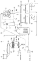
도 2 는 본 발명의 연료 펠릿의 제조 장치의 제 1 실시형태를 나타내는 플로우도이다.
도 3 은 제 1 실시형태의 연료 펠릿의 제조 장치에서 사용되는 롤러식 조립기를 나타내는 사시도이다.
도 4 는 제 1 실시형태의 연료 펠릿의 제조 장치를 사용하여 연료 펠릿의 제조 방법을 실시할 때의 플로우도이다.
도 5 는 본 발명의 연료 펠릿의 제조 장치의 제 2 실시형태를 나타내는 플로우도이다.
도 6 은 본 발명의 연료 펠릿의 제조 장치의 제 2 실시형태에 있어서의 롤러식 조립기의 폴리우레탄 도입구 근방의 상세를 나타내는 확대도이다.
도 7 은 제 2 실시형태의 연료 펠릿의 제조 장치를 사용하여 연료 펠릿의 제조 방법을 실시할 때의 플로우도이다. 1 is a perspective view showing an embodiment of a fuel pellet according to the present invention.
2 is a flow chart showing a first embodiment of the apparatus for producing fuel pellets of the present invention.
It is a perspective view which shows the roller type granulator used in the manufacturing apparatus of the fuel pellet of 1st Embodiment.
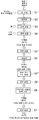
FIG. 4 is a flowchart when a fuel pellet manufacturing method is performed using the fuel pellet manufacturing apparatus of the first embodiment. FIG.
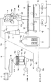
Fig. 5 is a flowchart showing a second embodiment of the apparatus for producing fuel pellets of the present invention.
It is an enlarged view which shows the detail of the polyurethane inlet vicinity of the roller type granulator in 2nd Embodiment of the manufacturing apparatus of the fuel pellet of this invention.
FIG. 7 is a flowchart when a fuel pellet manufacturing method is performed using the fuel pellet manufacturing apparatus of the second embodiment. FIG.
〈제 1 실시형태〉<1st embodiment>
도 1 은 본 발명에 관련된 연료 펠릿의 실시형태를 나타내는 사시도이다. 본 발명에 관련된 연료 펠릿 (P) 은, 폐기된 가전 제품으로부터 회수되는 경질의 우레탄폼을 파쇄하여 얻어지는 분상의 폴리우레탄을 압축 성형하여 형성된다. 또, 연료 펠릿 (P) 은, 부피 비중이 0.45 ? 0.55, 잔류 염소 농도가 0.3 중량퍼센트 이하로 각각 설정되어 있다. 또, 연료 펠릿 (P) 은, 길이 (L) 와 직경 (D) 의 비 (L/D) 가 4 ? 15 인 원기둥 형상으로 형성되어 있고, 저위 발열량은 6700 kcal/㎏ ? 7200 kcal/㎏ 이다.1 is a perspective view showing an embodiment of a fuel pellet according to the present invention. The fuel pellet P according to the present invention is formed by compression molding a powdery polyurethane obtained by crushing hard urethane foam recovered from discarded household electrical appliances. In addition, the fuel pellet P has a volume specific gravity of 0.45? 0.55 and residual chlorine concentration are respectively set to 0.3 weight% or less. In addition, the fuel pellet P has a ratio L / D of the length L and the diameter D of 4? It is formed in a cylindrical shape of 15, and the lower calorific value is 6700 kcal / kg? 7200 kcal / kg.
연료 펠릿 (P) 은, 도 2 및 도 3 에 나타내는 본 발명에 관련된 제 1 실시형태인 연료 펠릿의 제조 장치를 사용하여 형성된다. 도 2 는 본 발명의 연료 펠릿의 제조 장치의 제 1 실시형태를 나타내는 플로우도, 도 3 은 도 2 에 나타내는 제 1 실시형태의 연료 펠릿의 제조 장치에서 사용되는 롤러식 조립기 (예를 들어, 주식회사 미이케 철공소 제조) 를 나타내는 사시도이다. 또한, 도 2 및 도 3 에 나타내는 제 1 실시형태의 연료 펠릿의 제조 장치는, 주로 프레온 발포의 폴리우레탄으로부터 연료 펠릿을 제조하는 장치이다.The fuel pellet P is formed using the manufacturing apparatus of the fuel pellet which is 1st Embodiment which concerns on this invention shown in FIG. 2 and FIG. FIG. 2 is a flow diagram showing a first embodiment of the fuel pellet manufacturing apparatus of the present invention, and FIG. 3 is a roller granulator used in the fuel pellet manufacturing apparatus of the first embodiment shown in FIG. Miike Iron Works Co., Ltd.). In addition, the manufacturing apparatus of the fuel pellet of 1st Embodiment shown in FIG. 2 and FIG. 3 is an apparatus which manufactures fuel pellet mainly from the polyurethane of Freon foaming.
도 2 에 나타내는 바와 같이, 도시하지 않은 전단(前段)의 파쇄기에 연결되는 컨베이어 (1) 의 선단은 2 가닥으로 나누어지고, 그들 선단에는 댐퍼 (1a, 1b) 를 개재하여 저류조 (2a, 2b) 가 각각 접속된다. 저류조 (2a, 2b) 는, 컨베이어 (1) 에 의해 반송되는, 폐기된 가전 제품으로부터 회수되는 경질의 우레탄폼을 파쇄하여 얻어지는 분상의 폴리우레탄 (이하, 폴리우레탄 분체 (A) 라고 함) 을 저장한다. 이들 저류조 (2a, 2b) 의 유출구에는 스크루 피더 (3a, 3b) 의 유입구가 접속되고, 이들 스크루 피더 (3a, 3b) 의 유출구는 폴리우레탄 도입로 (4a) 를 개재하여 롤러식 조립기 (4) 에 접속된다. As shown in FIG. 2, the tip of the conveyor 1 connected to the front-end crusher which is not shown in figure is divided into 2 strands, and these front ends are provided with the
또한, 상기 컨베이어 (1), 상기 댐퍼 (1a, 1b), 상기 저류조 (2a, 2b), 상기 스크루 피더 (3a, 3b) 및 상기 폴리우레탄 도입로 (4a) 는, 롤러식 조립기 (4) 에 폴리우레탄 분체 (A) 를 공급하는 폴리우레탄 공급 수단을 구성한다.Further, the conveyor 1, the
도 3 에 나타내는 바와 같이, 롤러식 조립기 (4) 는, 케이싱 (5) 내에 링 형상 다이 (6) 와, 그 내측에 링 형상 다이 (6) 에 대하여 편심하여 배치되는 프레스롤 (7) 을 구비한다. 링 형상 다이 (6) 는, 링 형상의 본체 벽체 (6a) 에 방사 방향을 따라 복수의 성형용 구멍 (6b) 이 형성되어 있다. 성형용 구멍 (6b) 은, 깊이 (L) 와 구멍 직경 (D) 의 비 (L/D) 가 4 ? 15 로 설정된다. 링 형상 다이 (6) 는 모터 (8 과 9) 에 의해 회전된다. 프레스롤 (7) 은 유성(遊星)식으로 되어 있다. 링 형상 다이 (6) 의 외주에는 커터 (10) 가 배치되어 있다.As shown in FIG. 3, the
롤러식 조립기 (4) 에 공급된 폴리우레탄 분체 (A) 는, 링 형상 다이 (6) 와 프레스롤 (7) 에 의해 압축되어, 링 형상 다이의 성형용 구멍 (6b) 으로부터 원기둥 형상으로 성형되어 압출되고, 커터 (10) 에 의해 소정의 길이로 절단되어 연료 펠릿 (P) 이 형성된다. 즉, 롤러식 조립기 (4) 는, 분상의 폴리우레탄을, 링 형상 다이 (6) 와 다이의 내측에 배치된 프레스롤 (7) 사이에 개재시켜, 다이의 성형용 구멍 (6b) 으로부터 압출함으로써 연료 펠릿을 압축 성형하는 조립 수단을 구성한다.The polyurethane powder A supplied to the
도 2 에 나타내는 바와 같이, 롤러식 조립기 (4) 에는 탈기 통로 (11a) 를 개재하여 사이클론 (11) 이 접속되고, 사이클론 (11) 의 더욱 선단에는 가스 통로 (12a) 를 개재하여 버그 필터 (12) 가 접속되어 있다. 또, 버그 필터 (12) 의 하류에는 강제 배기용 블로어 (12b) 가 접속되어 있다. As shown in FIG. 2, the
블로어 (12b) 가 구동되면, 롤러식 조립기 (4) 내가 대기압보다 부압이 되고, 폴리우레탄 분체 (A) 로부터 분리된 프레온 및 수증기가, 롤러식 조립기 (4) 내로부터 사이클론 (11), 버그 필터 (12) 를 통과하여 배출된다. 블로어 (12b) 의 토출구에는 기존의 활성탄 흡착 설비가 접속되어 있다. 또, 상기 폴리우레탄 도입로 (4a) 에는 에어 도입로 (4aa) 가 접속되어 있어, 상기 롤러식 조립기 (4) 내가 대기압보다 부압이 될 때, 이 에어 도입로 (4aa) 로부터 외부 에어가 도입된다.When the
롤러식 조립기 (4) 의 유출구에는 밀폐형으로 강철제의 체인 컨베이어 (13) 의 기단이 접속되고, 이 밀폐식 체인 컨베이어 (13) 의 선단은 로터리 밸브 (13a) 를 개재하여 공랭식 냉각탑 (14) 에 접속된다. 체인 컨베이어 (13) 의 하류에는 에어 도입로 (13b) 가 형성되어, 상기 롤러식 조립기 (4) 및 이 롤러식 조립기 (4) 에 연통되는 밀폐형의 체인 컨베이어 (13) 내가 대기압보다 부압이 될 때, 이 에어 도입로 (13b) 로부터 냉각용의 외부 에어가 도입된다.A proximal end of the
공랭식 냉각탑 (14) 은 각뿔 종형의 냉각탑이다. 공랭식 냉각탑 (14) 의 정상부 내측에는 경사 갤러리 (14a) 가 형성되고, 상기 로터리 밸브 (13a) 로부터 공급되는 연료 펠릿 (P) 은, 이 경사 갤러리 (14a) 를 통과함으로써 분산 낙하되어, 하방의 바닥판 (14b) 에 균일한 두께로 적층된다. 바닥판 (14b) 은, 공기 분출구를 갖는 띠 형상의 가스 분산판을 구비한다. 또, 공랭식 냉각탑 (14) 의 직동부(直胴部) 하부에는 공기 도입구 (14c) 가, 바닥판 (14b) 보다 하방에 형성된다. 공랭식 냉각탑 (14) 의 내부 공간에 연통되는 배기 블로어 (15) 에 의해 당해 공랭식 냉각탑 (14) 내가 부압으로 유지될 때, 상기 공기 도입구 (14c) 로부터 외부 에어가 도입된다. 이 도입된 외부 에어는 공랭식 냉각탑 (14) 내의 공간을 하방으로부터 상방으로 흐르고, 이로써, 바닥판 (14b) 상에 적층된 연료 펠릿 (P) 이 냉각된다.The air-cooled
바닥판 (14b) 은, 회전 수단 (14d) 에 의해 설정 시간마다 혹은 연료 펠릿 (P) 의 온도에 따라 간헐적으로 회전된다. 이로써, 소정량 적층된 연료 펠릿 (P) 이 공랭식 냉각탑 (14) 의 하류에 접속된 진동 피더 (16) 로 반출된다.The
진동 피더 (16) 는 32 ? 36 메시의 스크린을 구비한다. 진동 피더 (16) 로 반출된 연료 펠릿 (P) 에 동반되는 분체 혹은 부스러기 펠릿 등은, 이 스크린에 의해 체에 걸러져 떨어진다. 분진 등이 체에 걸러져 떨어진 연료 펠릿 (P) 은, 출하용 컨테이너 (17) 혹은 플렉시블 컨테이너 백에 공급된다. The
진동 피더 (16) 에는 에이프런 컨베이어 (18) 가 접속되어, 이 에이프런 컨베이어 (18) 에서 회수된 분체 및 부스러기 펠릿은, 상기 저류조 (2a, 2b) 로 운반되어 다시 펠릿 원료로서 이용된다. 또, 사이클론 (11) 및 버그 필터 (12) 에서 포집된 배기 가스 (프레온 및 수증기) 중의 우레탄 더스트는, 각각에 부대의 로터리 밸브 (11b, 12c) 로부터 반출되어, 에이프런 컨베이어 (18a) 를 통해 상기 에이프런 컨베이어 (18) 에 합류되고, 이곳으로부터 상기 저류조 (2a, 2b) 에 반송된다.An
여기서, 상기 공랭식 냉각탑 (14) 은, 상기 조립 수단인 롤러식 조립기 (4) 에 의해 압축 성형된 연료 펠릿 (A) 을 냉각시키는 냉각 수단을 구성한다. 또, 밀폐식 체인 컨베이어 (13) 는, 상기 조립 수단인 롤러식 조립기 (4) 에 의해 압축 성형된 연료 펠릿 (A) 을 상기 냉각 수단인 공랭식 냉각탑 (14) 에 반송하는 반송 수단을 구성한다. 덧붙여서, 이 밀폐식 체인 컨베이어 (13) 는, 압축 성형된 연료 펠릿 (A) 을 공랭식 냉각탑 (14) 에 반송할 때까지의 사이에, 에어를 이용하여 예비적으로 냉각시키는 냉각 수단을 겸하고 있다. 또, 블로어 (12b) 및 배기 블로어 (15) 는, 상기 조립 수단인 롤러식 조립기 (4) 와 상기 반송 수단인 밀폐식 체인 컨베이어 (13) 내를 소정의 부압 분위기로 유지하는 부압 수단을 구성한다.Here, the said air-cooled
도 4 는 제 1 실시형태의 연료 펠릿의 제조 장치를 사용하여 연료 펠릿을 제조할 때의 플로우도이다. 이 도면을 따라, 본 발명의 연료 펠릿의 제조 방법을 설명한다.4 is a flow chart when manufacturing fuel pellets using the fuel pellet manufacturing apparatus of the first embodiment. According to this figure, the manufacturing method of the fuel pellet of this invention is demonstrated.
먼저, 폐기된 예를 들어 냉장고, 냉동고, 세탁기, 에어컨 등의 가전 제품을 수동으로 해체하고 (단계 S1), 제품 본체로부터 유가물(有價物)을 회수하고, 파쇄에 적합하지 않은 것을 분리한다.First, dismantled household appliances such as a refrigerator, a freezer, a washing machine, an air conditioner, and the like are manually dismantled (step S1), the valuables are recovered from the product main body, and those that are not suitable for crushing are separated.
이어서, 잔존하는 해체한 제품 본체를 파쇄기로 조(粗)파쇄한다 (단계 S2). 계속해서, 자력 선별에 의해 파쇄 조각으로부터 철계의 재료를 선별한다 (단계 3). 이어서, 풍력 선별에 의해 수지나 비철로 이루어지는 파쇄 조각과 폴리우레탄 파쇄 조각을 선별한다 (단계 S4). 이 때의 폴리우레탄 파쇄 조각의 부피 비중은 0.035 정도이다. Next, the remaining disassembled product body is roughly crushed by a crusher (step S2). Subsequently, the iron-based material is selected from the crushed pieces by magnetic screening (step 3). Next, the crushed pieces and the polyurethane crushed pieces made of resin or non-ferrous are sorted by wind power sorting (step S4). The volume specific gravity of the polyurethane crushed pieces at this time is about 0.035.
다음으로, 폴리우레탄 파쇄 조각을 파쇄기로 더욱 미세하게 파쇄한다 (단계 S5). 이로써, 직경 10 ㎜ 이하 (적합치는 5 ㎜ 이하) 의 폴리우레탄 분체를 얻는다. 폴리우레탄 분체는 입상인 것과 다른 형상인 것이 혼재되어 있고, 직경 10 ㎜ 이하란, 여기서는 폴리우레탄 파쇄 조각의 최대 길이가 10 ㎜ 이하인 것을 의미한다. 폴리우레탄 분체를 10 ㎜ 이하로 하는 것은, 종전이라면, 프레스 성형에 의해 스폰지 케이크를 형성하기 위해서이지만, 이것을 그대로 이용하여 롤러식 조립기 (4) 에서 연료 펠릿 (P) 을 지장없이 형성하기 위해서이다. 또한, 이 때의 폴리우레탄 분체의 부피 비중은 0.06 정도이다. Next, the polyurethane crushed pieces are more finely crushed with a crusher (step S5). Thereby, the polyurethane powder of diameter 10mm or less (suitable value 5mm or less) is obtained. Polyurethane powder is a thing different from a granular thing is mixed, and a diameter of 10 mm or less means that the maximum length of a polyurethane crushed piece is 10 mm or less here. Although it is conventional in order to form a sponge cake by press molding, polyurethane powder is 10 mm or less in order to form fuel pellet P in the
이상은, 종래부터 가전 리사이클 플랜트에서 실시되고 있는 공정이다.The above is the process currently performed by the household electrical appliance recycling plant.
다음으로, 전술한 제 1 실시형태의 연료 펠릿의 제조 장치를 사용하여, 폴리우레탄 분체를 압축 성형하고, 본 발명에 관련된 연료 펠릿 (P) 을 압축 성형함과 함께 (단계 S6), 성형된 연료 펠릿 (P) 을 소정 온도까지 냉각시킨다 (단계 S7).Next, the polyurethane powder is compression molded using the fuel pellet manufacturing apparatus of the first embodiment described above, and the fuel pellet P according to the present invention is compression molded (step S6), and the molded fuel is molded. The pellet P is cooled to a predetermined temperature (step S7).
구체적으로는, 상기 단계 S5 에서 얻어진 폴리우레탄 분체 (A) 를 컨베이어 (1) 에 의해 반송하고, 댐퍼 (1a, 1b) 를 통해 저류조 (2a, 2b) 에 저류한다.Specifically, the polyurethane powder A obtained in the step S5 is conveyed by the conveyor 1 and stored in the
저류한 폴리우레탄 분체 (A) 를 저류조 (2a, 2b) 로부터 스크루 피더 (3a, 3b) 에 의해 롤러식 조립기 (4) 에 정량 공급한다. 또한, 스크루 피더 (3a, 3b) 는 통상 교호 운전한다. 이 때의 폴리우레탄 분체 (A) 의 공급량은 200 ㎏/h ? 500 ㎏/h 사이로 조정하는데, 300 ㎏/h ? 400 ㎏/h 의 범위가 바람직하다.The polyurethane powder A stored is quantitatively supplied to the
정량 잘라내어진 폴리우레탄 분체 (A) 는 중력 낙하류에 의해 폴리우레탄 도입로 (4a) 를 통해 롤러식 조립기 (4) 에 투입된다. 이 때, 분리된 프레온 및 수증기 (후술) 의 상승류에 의해 중력 낙하가 저해될 우려가 있다. 이 실시형태에서는, 블로어 (12b) 에 의해 롤러식 조립기 (4) 를 부압으로 유지하는 것에 수반하여, 에어 도입로 (4aa) 로부터 에어가 도입되고, 이 도입된 에어의 흐름에 의해, 폴리우레탄 분체 (A) 가 스크루 피더 (3a, 3b) 측으로부터 롤러식 조립기 (4) 측으로 신속하게 흐른다.Quantitatively cut-out polyurethane powder (A) is thrown into the
롤러식 조립기 (4) 내에 유입된 폴리우레탄 분체 (A) 는, 링 형상 다이 (6) 와 프레스롤 (7) 에 의해 압축되어, 링 형상 다이의 성형용 구멍 (6b) 으로부터 원기둥 형상으로 성형되어 압출되고, 커터 (10) 에 의해 소정의 길이로 절단되어 연료 펠릿 (P) 이 형성된다.The polyurethane powder A introduced into the
이와 같이, 폴리우레탄 분체로부터 롤러식 조립기 (4) 를 사용하여 직접 연료 펠릿을 압축 성형하는 방법은, 압축 효율이 좋아, 종래의 유압 프레스에 의해 스폰지 케이크 형상을 생성하는 경우에 비해, 출력이 약 절반 정도인 모터 (110 kw) 를 사용해도 충분히 압축 성형할 수 있다. 따라서, 소비 전력도 작다.Thus, the method of compression molding fuel pellets directly from the polyurethane powder using the
롤러식 조립기 (4) 에서 폴리우레탄 분체 (A) 가 압축 성형될 때에, 폴리우레탄 분자간에 존재하는 혹은 분자에 고용되는, 폴리우레탄의 발포에 사용된 프레온 (R11 및 프레온 (141b)), 그리고 폴리우레탄 분체 (A) 에 포함되는 수분이, 압축시에 발생하는 마찰열 및 압축열에 의해 가열되고, 우레탄 분자로부터 분리된다.When the polyurethane powder A is compression molded in the
이 마찰열 혹은 압축열에 의한 조립 온도는 140 ℃ ? 160 ℃ 의 범위에 있다. 또한, 조립 온도가 140 ℃ 보다 낮으면 폴리우레탄 분체 (A) 내의 프레온이나 에어의 팽창이 억제되기 때문에, 그들 폴리우레탄 분체 (A) 로부터의 프레온 등의 분리가 억제된다. 또, 조립 온도가 160 ℃ 보다 높으면, 분리되는 가스 (프레온, 수증기) 의 양이 증가하여 확산이 불충분해져 튕겨져 나간 불량 펠릿이 많이 형성된다. 조립 온도는, 공급되는 폴리우레탄 분체 (A) 의 양에 의해 변화되지만, 145 ℃ ? 155 ℃ 가 되도록, 롤러식 조립기 (4) 에 대한 폴리우레탄 분체 (A) 의 공급량을 조정하는 것이 바람직하다.The assembly temperature by this frictional heat or compression heat is 140 ° C? It is in the range of 160 ° C. In addition, when the granulation temperature is lower than 140 ° C, the expansion of freon and air in the polyurethane powder (A) is suppressed, so that the separation of freon and the like from the polyurethane powder (A) is suppressed. In addition, when the granulation temperature is higher than 160 ° C., the amount of gas (freon, water vapor) to be separated increases, so that diffusion is insufficient, and many defective pellets are thrown out. Although granulation temperature changes with the quantity of the polyurethane powder (A) supplied, it is 145 degreeC? It is preferable to adjust the supply amount of the polyurethane powder (A) to the
폴리우레탄 분체 (A) 로부터 분리된 프레온 및 수증기는, 탈기 통로 (11a), 사이클론 (11), 및 버그 필터 (12) 를 경유하여 블로어 (12b) 에서 강제 배기된다. 이 때의 배기 풍량은 15 ㎥/min ? 30 ㎥/min 의 범위로 설정된다. 배기 풍량이 15 ㎥/min 미만이면, 분리된 가스 (프레온, 수증기) 를 효과적으로 배출할 수 없다. 또, 배기 풍량이 30 ㎥/min 를 초과하면, 배기되는 가스 (프레온, 수증기) 에 동반되는 폴리우레탄 분체 (A) 의 양이 현저하게 많아진다. 보다 바람직한 배기 풍량은 20 ㎥/min ? 26 ㎥/min 이다. Freon and water vapor separated from the polyurethane powder (A) are forced out of the blower (12b) via the degassing passage (11a), the cyclone (11), and the bug filter (12). The exhaust air volume at this time is 15 m3 / min? It is set in the range of 30 m 3 / min. If the amount of exhaust air is less than 15 m 3 / min, the separated gases (freon, water vapor) cannot be effectively discharged. Moreover, when the amount of exhaust air exceeds 30 m 3 / min, the amount of the polyurethane powder (A) accompanying the gas (freon, water vapor) to be exhausted becomes remarkably large. More preferable exhaust air volume is 20 m3 / min? 26 m 3 / min.
이 때, 롤러식 조립기 (4) 의 내부는, 압력이 대기보다 147 ㎩ ? 245 ㎩ (15 ㎜H2O ? 25 ㎜H2O) 낮은 부압 분위기로 유지된다. 롤러식 조립기 (4) 의 내부를 상기와 같은 소정 부압 분위기로 유지하는 것은, 상기 배기 풍량을 결정한 이유와 동일하다.At this time, the inside of the
또한, 배기 블로어 (12b) 에 의해 배기된 프레온을 함유한 가스는, 기존의 활성탄 흡착 설비에 도입되고, 프레온 회수가 실시된다.In addition, the gas containing the Freon exhausted by the
이와 같이, 회수한 폴리우레탄 분체 (A) 로부터 길이 (L) 와 직경 (D) 의 비 (L/D) 가 4 ? 15, 부피 비중 0.45 ? 0.55, 저위 발열량 6700 ? 7200 kcal/㎏, 잔류 염소 농도 0.25 ? 0.30 중량퍼센트인 원기둥형의 연료 펠릿 (P) 을 제조한다. 연료 펠릿 (P) 을 상기 조건으로 하려면, 원료 공급량?조립 온도?배기 풍량?내부 압력을 적절히 컨트롤하는 것이 중요하다. 이 실시형태에 있어서의 적합치를 하기의 표 1 에 나타낸다. Thus, ratio (L / D) of length (L) and diameter (D) is 4 to 4 from the recovered polyurethane powder (A). 15, volume specific gravity 0.45? 0.55, low calorific value 6700? 7200 kcal / kg, residual chlorine concentration 0.25? A cylindrical fuel pellet P is prepared which is 0.30% by weight. In order to make fuel pellet P into the said conditions, it is important to control raw material supply quantity, an assembly temperature, exhaust air volume, and internal pressure suitably. The suitability in this embodiment is shown in Table 1 below.

형성된 연료 펠릿 (P) 은, 롤러식 조립기 (4) 에 내장된 커터 (10) 에 의해 길이 10 ? 30 ㎜ 정도로 정립(整粒)된 후, 배출구로부터 배출되어, 밀폐형 체인 컨베이어 (13) 를 거쳐 공랭식 냉각탑 (14) 에 반송된다. The formed fuel pellets P are formed by the
배출 직후의 펠릿 온도는 142 ℃ ? 155 ℃ 이고, 난연성 또한 방열성이 우수한 강철제의 체인 컨베이어 (13) 에 의해 반송함으로써 냉각 효과를 갖게 함과 동시에, 체인 컨베이어 (13) 의 하류의 에어 도입로 (13b) 로부터 냉각용의 외부 에어를 도입하여, 이 외부 에어에 의해 연료 펠릿 (P) 을 예랭시킨다. 이 결과, 예랭 후의 연료 펠릿 (P) 의 온도는 70 ℃ ? 90 ℃ 정도까지 냉각된다.The pellet temperature immediately after discharging is 142 ° C. By conveying by the
체인 컨베이어 (13) 에 의해 공랭식 냉각탑 (14) 에 반송된 연료 펠릿 (P) 은, 로터리 밸브 (13a) 를 통해 공랭식 냉각탑 (14) 의 경사 갤러리 (14a) 에 의해 분산 낙하하여, 바닥판 (14b) 상에 균일한 두께로 적층된다. 이 실시형태에서는, 냉각 효과를 고려하여 적층 두께를 100 ㎜ ? 150 ㎜ 의 범위로 설정한다.The fuel pellets P conveyed to the air-cooled
바닥판 (14b) 상에 적층된 연료 펠릿 (P) 은, 배기 블로어 (15) 가 구동되는 것에 수반하여, 공기 도입구 (14c) 로부터 도입되는 외부 에어에 의해 25 ℃ ? 45 ℃ 의 범위가 될 때까지 냉각된다.Fuel pellet P laminated | stacked on the
하기 표 2 에 연료 펠릿 (P) 의 온도 추이를 나타낸다.In Table 2 below, the temperature change of the fuel pellet P is shown.

바닥판 (14b) 은 회전 수단 (14d) 에 의해 설정 시간마다 혹은 연료 펠릿의 온도에 따라 간헐적으로 회전하여, 소정량 적층된 연료 펠릿 (P) 을 진동 피더 (16) 로 배출한다. The
배출된 연료 펠릿 (P) 은, 진동 피더 (16) 에 의해 출하용 컨테이너 (17) 혹은 플렉시블 컨테이너 백에 공급된다.The discharged fuel pellets P are supplied to the
연료 펠릿 (P) 이 진동 피더 (16) 의 스크린을 통과할 때, 그 연료 펠릿 (P) 에 동반되는 분체 혹은 부스러기 펠릿 등은, 이 스크린에 의해 체에 걸러져 떨어진다. 스크린에 의해 체에 걸러져 떨어진 폴리우레탄 분체 및 부스러기 펠릿은, 에이프런 컨베이어 (18) 에 의해 회수되어, 저류조 (2a, 2b) 로 운반되어 다시 펠릿 원료로서 이용된다.When the fuel pellets P pass through the screen of the vibrating
이상 설명한 바와 같이 본 발명에 관련된 연료 펠릿 (P) 에 의하면, 잔류 염소 농도가 0.3 중량퍼센트 이하로 설정되어 있기 때문에, 통상적인 소각로나 보일러 등의 연료용으로서 이용할 수 있다. 덧붙여서, 잔류 염소 농도가 0.3 중량퍼센트를 초과하는 값이면, 잔류 염소 허용 농도가 높은 용광로 연료 혹은 철 환원제 등의 특수한 연료로밖에 사용할 수 없다. 또, 부피 비중이 0.45 ? 0.55 로 설정되어 있기 때문에, 충분히 압밀되어 있어, 수송시의 비용을 저감시킬 수 있음과 함께, 분진의 발생을 억제할 수 있다. As explained above, according to the fuel pellet P which concerns on this invention, since residual chlorine concentration is set to 0.3 weight% or less, it can use for fuels, such as a normal incinerator, a boiler, and the like. In addition, as long as the residual chlorine concentration exceeds 0.3 weight percent, it can only be used as a special fuel, such as a blast furnace fuel or an iron reducing agent with a high residual chlorine allowable concentration. Moreover, the volume specific gravity is 0.45? Since it is set to 0.55, it is fully consolidated, the cost at the time of transport can be reduced, and generation | occurrence | production of dust can be suppressed.
덧붙여서, 상기 연료 펠릿 (P) 은, 길이 (L) 와 직경 (D) 의 비 (L/D) 가 4 ? 15 인 원기둥 형상으로 성형되어 있기 때문에, 취급이 용이하며 또한 건조나 냉각 효율도 우수하다. 또, 길이 (L) 와 직경 (D) 의 비 (L/D) 가 4 미만이면 높은 압밀을 할 수 없고, 길이 (L) 와 직경 (D) 의 비 (L/D) 가 15 를 초과하면 탈기를 양호하게 실시할 수 없어, 잔류 염소 농도를 0.3 중량퍼센트 이하로 설정하는 것이 곤란해진다. Incidentally, the fuel pellet P has a ratio L / D of length L and diameter D of 4? Since it is molded into a 15-membered cylindrical shape, it is easy to handle and excellent in drying and cooling efficiency. If the ratio (L / D) of the length (L) and the diameter (D) is less than 4, high consolidation cannot be achieved, and if the ratio (L / D) of the length (L) and the diameter (D) exceeds 15, Degassing cannot be performed satisfactorily and it becomes difficult to set residual chlorine concentration to 0.3 weight% or less.
〈제 2 실시형태〉<2nd embodiment>
도 5 는 본 발명의 연료 펠릿의 제조 장치의 제 2 실시형태를 나타내는 플로우도, 도 6 은 본 발명의 연료 펠릿의 제조 장치의 제 2 실시형태에 있어서의 롤러식 조립기의 폴리우레탄 도입구 근방의 상세를 나타내는 확대도, 도 7 은 제 2 실시형태의 연료 펠릿의 제조 장치를 사용하여 연료 펠릿의 제조 방법을 실시할 때의 플로우도이다. FIG. 5 is a flow chart showing a second embodiment of the fuel pellet manufacturing apparatus of the present invention, and FIG. 6 is a polyurethane inlet vicinity of the roller granulator in the second embodiment of the fuel pellet manufacturing apparatus of the present invention. An enlarged view showing details. FIG. 7 is a flow diagram when a fuel pellet manufacturing method is performed using the fuel pellet manufacturing apparatus of the second embodiment.
또한, 설명의 편의상, 이 제 2 실시형태의 연료 펠릿의 제조 장치 및 제조 방법에 있어서, 도 2 및 도 4 에서 나타내는 제 1 실시형태의 연료 펠릿의 제조 장치 및 제조 방법과 동일한 구성 요소에 대해서는 동일한 부호를 부여하고, 그 설명을 생략한다.In addition, for convenience of description, in the manufacturing apparatus and manufacturing method of the fuel pellet of this 2nd Embodiment, about the same component as the manufacturing apparatus and manufacturing method of the fuel pellet of 1st Embodiment shown in FIG. 2 and FIG. A code | symbol is attached | subjected and the description is abbreviate | omitted.
제 2 실시형태의 연료 펠릿의 제조 장치 및 제조 방법은, 주로 시클로펜탄 발포의 폴리우레탄으로부터 연료 펠릿을 제조하는 데에 사용하기 바람직한 연료 펠릿의 제조 장치 및 제조 방법이다. The manufacturing apparatus and manufacturing method of the fuel pellet of 2nd Embodiment are the manufacturing apparatus and manufacturing method of the fuel pellet which are mainly used for manufacturing a fuel pellet from the cyclopentane foamed polyurethane.
시클로펜탄 발포의 폴리우레탄은, 시클로펜탄 자체가 인화성이기 때문에, 이것으부터 연료 펠릿을 제조하려면 방재상의 대책이 필요하다. Since cyclopentane itself is flammable, polyurethane of cyclopentane foaming requires disaster prevention measures to manufacture fuel pellets from this.
도 5 및 도 6 에 나타내는 바와 같이, 제 2 실시형태의 연료 펠릿의 제조 장치는, 폴리우레탄 도입로 (4a) 의 롤러식 조립기 (4) 에 대한 접속부를 둘러싸도록 호퍼 (21) 를 구비하고 있고, 이 호퍼 (21) 에는 불활성 가스를 도입하기 위한 불활성 가스 도입로 (22) 가, 그 호퍼의 측벽 (21a) 을 관통하여 폴리우레탄 도입로 (4a) 에 이르도록 배치 형성되어 있다. 이 불활성 가스 도입로 (22) 로부터는 예를 들어 질소 가스 혹은 아르곤 가스 등의 불활성 가스가 도입된다. 불활성 가스의 도입은, 예를 들어, 블로어 (12b) 가 구동되어 롤러식 조립기 (4) 내가 부압이 될 때, 그 부압을 이용하여 롤러식 조립기 (4) 내에 도입된다. 또, 불활성 가스가 보다 많이 필요한 경우에는, 불활성 가스 도입로 (22) 의 기단측에 도시하지 않은 블로어를 설치하고, 이 블로어의 압력을 이용하여 강제적으로 롤러식 조립기 (4) 내에 도입시켜도 된다.As shown to FIG. 5 and FIG. 6, the manufacturing apparatus of the fuel pellet of 2nd Embodiment is provided with the
이와 같이, 불활성 가스를 롤러식 조립기 (4) 내에 도입하는 것은, 롤러식 조립기 (4) 내에 있어서, 시클로펜탄 가스의 농도를 소정치 이하로까지 희석시키는 효과와, 롤러식 조립기 (4) 내의 산소 농도를 낮추는 효과에 의해, 롤러식 조립기 (4) 내에서의 싱크로펜 가스가 발화되는 것을 방지하거나, 혹은 발화되어도 소염을 용이하게 하기 위해서이다. 요컨대, 상기 불활성 가스 도입로 (22) 는, 불활성 가스를, 호퍼 (21) 및 롤러식 조립기 (4) 를 포함시킨 조립부 내에 도입하는 불활성 가스 도입 수단을 구성한다.Thus, introducing the inert gas into the
또, 호퍼 (21) 에는, 에어 도입로 (4aa) 가, 그 선단을 호퍼의 측벽 (21a) 내에서 개구하도록 접속되어 있다. 블로어 (12b) 가 구동되면, 그 블로어 (12b) 의 흡인력에 의해 에어 도입로 (4aa) 로부터 공기가 호퍼 (21) 내에 도입된다. 이 도입된 공기는 롤러식 조립기 (4) 내에 도입되는 상기 불활성 가스의 일부와 합류하여, 호퍼 (21) 에 접속된 탈기 통로 (11a) 를 통해 사이클론 (11) 으로 유도된다. 이와 같이 에어 도입로 (4aa) 를 통해 호퍼 (21) 내에 공기를 도입하는 것은, 롤러식 조립기 (4) 에서 발생한 우레탄 더스트 등을 사이클론이나 버그 필터 (12) 까지 운반하는 데에 필요한 풍량을 얻기 위해서이다.Moreover, the air introduction passage 4aa is connected to the
또, 호퍼 (21) 의 측벽 (21a) 내부에는 압력 센서 (23) 가 형성되어 있다. 이 압력 센서 (23) 는, 나이프 게이트 밸브 (24) 의 동작을 제어하거나, 분말 소화제를 롤러식 조립기 (4) 내에 도입하기 위한 제어를 실시하는 제어부 (도시 생략) 에 접속되어 있다. 상기 나이프 게이트 밸브 (24) 는, 동일한 장소에 분말 소화제를 분출하는 기구를 설치함으로써 대체할 수 있다. 호퍼 (21) 내에 도입되는 분말 소화제는, 시클로펜탄에 의한 화염을 억제하는 효과를 갖고, 호퍼 (21) 에 접속되어 있는 배관의 차단은 화염의 차단 효과를 갖는다. 이 경우, 특히 탈기 통로 (11a) 에 접속되어 있는 배관에서의 화염의 차단이 중요하고, 여기서 화염을 차단함으로써 집진계에서의 2차적인 피해가 생기는 것을 방지하는 효과가 있다. 이 집진계의 탈기 통로에는, 도 5 에 나타낸 펠릿 출구로부터의 탈기 통로 (11a) 도 합류하고 있고, 화염의 차단 기구는 합류 이후, 사이클론 (11) 의 앞까지 배치할 필요가 있다. 공기 혹은 질소 가스 도입 배관에 대해서는, 원래, 착화되는 물질이 존재하지 않기 때문에 소염만의 대응인 소염 벤트에 의해 대응도 가능하다. 화염 차단을 목적으로 한 나이프 게이트 밸브 (24) 또는 분말 소화제의 설치 장소는, 압력 센서 (23) 에서 압력을 감지하고 나서 그들 기기가 작동할 때까지의 시간과 화염의 속도로부터 산출되는 도달 거리 (시클로펜탄과 우레탄 분진의 하이브리드 상태에 있어서의 최대 ㎏ 값 = 260 으로 한 경우의 설치의 보안 거리는, 배관 직경 300 ㎜ 의 경우 2.5 ? 7.5 m), 호퍼 (21) 로부터 떨어진 장소이고, 호퍼에 접속하고 있는 3 개의 배관인 불활성 가스 도입로 (22), 에어 도입로 (4aa), 탈기 통로 (11a) 에 배치된다. 또, 화염 억제 효과를 갖는 분말 소화제는 호퍼 (21) 에 방출되도록 배치된다.In addition, a
그리고, 압력 센서 (23) 에 의해, 호퍼 (21) 내 혹은 그 호퍼 (21) 에 접속되는 롤러식 조립기 (4) 내의 압력이 이상적으로 높아진 것을 검지하면, 제어부로부터의 출력 신호에 기초하여, 나이프 게이트 밸브 (24) 가 폐색, 혹은 그 장소에 분말 소화제가 분출된다. 이로써, 호퍼 (21) 내에서 발생한 화염이, 불활성 가스 도입로 (22), 에어 도입로 (4aa), 탈기 통로 (11a) 를 통해서, 그들 통로의 호퍼와는 반대측의 접속단까지 전파되는 것을 방지한다. 또, 상기 제어부로부터의 출력 신호에 기초하여, 분말 소화제가 호퍼 (21) 에 방출됨으로써, 이상 압력의 원인이 되는 화염의 억제 효과를 발휘한다. And when the
요컨대, 상기 압력 센서 (23), 나이프 게이트 밸브 (24), 분말 소화제, 제어부는, 호퍼 (21) 내나 롤러식 조립기 (4) 내 (요컨대, 호퍼 (21) 및 롤러식 조립기 (4) 를 포함시킨 조립부 내) 에서 화염이 발생한 경우에, 그 영향이, 연료 펠릿의 제조 장치의 다른 구성 부분 (조립부 외) 까지 확산되지 않도록 억제하는 제 1 차단?억제 수단을 구성한다.In short, the
또, 호퍼 (21) 의 측벽에는 폭발 방산구 (25) 가 형성되어 있다. 이 폭발 방산구 (25) 는 통상 폐색되어 있지만, 이 폭발 방산구 (25) 가 장착되어 있는 공간 내, 예를 들어 호퍼 (21) 내의 압력이 이상적으로 높아진 경우에는, 즉시 개방되어 동일 공간 내의 압력을 외부로 개방한다. 또, 필요에 따라, 폭발 방산구 (25) 에 부수하여 소염 장치를 추가하여, 개방된 폭발 방산구로부터 외부로 화염이 방출되는 것을 방지하도록 해도 된다. Moreover, the
요컨대, 상기 폭발 방산구 (25) 혹은 폭발 방산구 (25) 에 부수하는 소염 장치는, 호퍼 (21) 내나 롤러식 조립기 (4) (상기 조립부) 내에서 폭발이 발생한 경우에, 그 영향이, 연료 펠릿의 제조 장치의 다른 구성 부분 (조립부 외) 까지 확산되지 않도록 억제하는 제 2 억제 수단을 구성한다.In other words, when the explosion occurs in the
또한, 제 2 실시형태의 연료 펠릿의 제조 장치에 의하면, 시클로펜탄 발포의 폴리우레탄을 처리하여 연료 펠릿을 제조하기 위한 방재상의 대책으로서, 불활성 가스 도입 수단, 제 1 차단?억제 수단, 제 2 억제 수단을 각각 구비하고 있지만, 이들 모든 수단을 반드시 구비할 필요는 없고, 그들 중 어느 1 개, 혹은 어느 2 개를 구비하도록 해도 된다.In addition, according to the fuel pellet manufacturing apparatus of the second embodiment, as an anti-disaster measure for treating fuel pellets by processing a polyurethane of cyclopentane foaming, inert gas introduction means, first blocking-inhibiting means, and second suppressing means Although each means is provided, it is not necessary to necessarily provide all these means, You may provide any one or two of them.
도 7 에 나타내는 바와 같이, 제 2 실시형태의 연료 펠릿의 제조 방법에 의하면, 풍력 선별 (단계 S4) 에 의해 선별된 폴리우레탄 파쇄 조각을 파쇄기로 더욱 미세하게 파쇄하는 재파쇄 공정 (단계 S5) 전에, 폴리우레탄 파쇄 조각을 반송하는 반송로의 도중 혹은 선단에 예를 들어 드럼식의 자석 선별기를 형성함으로써, 폴리우레탄 파쇄 조각으로부터 철계의 재료를 선별하여 제거하는 자석 선별 (단계 S5′) 을 실시해도 된다. As shown in FIG. 7, according to the manufacturing method of the fuel pellet of 2nd Embodiment, before the recrushing process (step S5) which grind | pulverizes the polyurethane crushed piece selected by wind power sorting (step S4) more finely with a crusher. The magnet sorting (step S5 ') which sorts and removes iron-based material from a polyurethane shredding piece may be performed by forming a drum-type magnet sorting device in the middle of a conveyance path or the front end which conveys a shredding piece of polyurethane, for example. .
또한, 재파쇄된 폴리우레탄 분체를 롤러식 조립기 (4) 를 사용하여 연료 펠릿을 압축 성형하는 압축 공정 (단계 S6) 전에, 이 폴리우레탄 분체를 반송하는 반송로의 도중 혹은 선단에 예를 들어 드럼식의 자석 선별기를 형성함으로써, 폴리우레탄 분체로부터 철계의 재료를 선별하여 제거하는 자석 선별 (단계 S6′) 을 실시해도 된다. In addition, before the compression process (step S6) of compression-molding the fuel pellets using the
이와 같이, 자석 선별을 몇 번이나 실시하는 것은, 폴리우레탄 분체 중에 철계의 재료가 섞이면, 롤러식 조립기 (4) 를 사용하여 연료 펠릿을 압축 성형할 때에, 철계 재료의 마찰에 의해 불꽃이 생기고, 이것에서 기인하여 폴리우레탄 분체로부터 생기는 시클로펜탄 가스가 발화된다는 사태를 피하기 위해서이다.In this way, the magnet sorting is performed several times, when the iron-based material is mixed in the polyurethane powder, when the fuel pellet is compression-molded using the
또한, 이 제 2 실시형태에서 나타낸 바와 같이, 재파쇄의 전 공정과 조립기를 사용한 압축 공정의 전 공정의 2 번에 걸쳐서 자석 선별 공정 (단계 S5′, 단계 S6′) 을 실시할 필요는 없고, 그것들 중 하나의 공정으로 철계의 재료를 제거해도 된다.In addition, as shown in this second embodiment, it is not necessary to perform the magnet sorting process (step S5 ', step S6') over two times of the whole process of the re-crushing and the compression process using the granulator, You may remove an iron type material by one of those processes.
또, 이 제 2 실시형태의 연료 펠릿의 제조 방법에서는, 재파쇄된 폴리우레탄 분체를 롤러식 조립기 (4) 를 사용하여 연료 펠릿을 압축 성형하는 압축 공정 (단계 S6) 이 실시되는 지점까지, 폴리우레탄 분체를 반송함에 있어서, 이 반송로에, 불꽃 검지기와, 이 불꽃 검지기로부터의 검지 신호에 기초하여 당해 반송로에 물을 산포하는 살수기를 구비하는 구성으로 하여 (단계 S5′′), 불꽃의 발생을 억제하면서 반송하는 구성으로 해도 된다. 이와 같이, 폴리우레탄 분체의 반송 중에 불꽃의 발생을 억제하는 것은, 반송 중에 생기는 불꽃에서 기인하여 폴리우레탄 분체로부터 생기는 시클로펜탄 가스가 발화된다는 사태를 피하기 위해서이다.Moreover, in the manufacturing method of the fuel pellet of this 2nd Embodiment, until the point where the compression process (step S6) of compression molding a fuel pellet using the
또한, 불꽃의 발생을 억제하는 수단으로는, 불꽃 검지기와 살수기의 조합 외에, 습도계와 살수기의 조합도 생각할 수 있다. Moreover, as a means of suppressing generation | occurrence | production of a flame, the combination of a hygrometer and a water dispenser can be considered besides the combination of a flame detector and a water dispenser.
즉, 습도계에 의해 반송로 상의 습도를 항상 검지하여, 습도가 소정치 이하가 되는 경우에는, 살수기로부터 물을 산포함으로써, 반송로 상의 습도를 항상 소정치 이상으로 유지하는 것에 의해, 정전기가 원인으로 생기는 불꽃의 발생을 방지할 수 있다. 또, 반송 중의 분말 유체에 의해 발생하는 정전기를 제거하기 위해서, 이들의 배관 및, 호퍼 (21), 밀은 정전 접지를 실시하여, 정전 제거를 실시하는 것도 중요하다.In other words, when the humidity on the conveyance path is always detected by the hygrometer and the humidity becomes less than the predetermined value, by dispersing water from the sprinkler, the humidity on the conveyance path is always kept above the predetermined value, thereby causing static electricity. The generation of sparks can be prevented. Moreover, in order to remove the static electricity generated by the powder fluid during conveyance, it is also important that these pipes, the
이와 같은, 연료 펠릿의 제조 장치 혹은 제조 방법에 의하면, 방재상의 대책을 채택하고 있기 때문에, 장치 내에서 시클로펜탄의 가스 혹은 액이 연소되는 것을 회피할 수 있다. 또, 만일 시클로펜탄의 가스가 연소되는 경우에도, 그 영향을 최소한으로 저지할 수 있다.According to such a fuel pellet manufacturing apparatus or a manufacturing method, since disaster prevention measures are adopted, it is possible to avoid the combustion of the gas or liquid of the cyclopentane in the apparatus. Moreover, even if the gas of cyclopentane is combusted, the influence can be suppressed to the minimum.
또한, 본 발명은 전술한 실시형태에 한정되는 것은 아니고, 본 발명의 취지를 일탈하지 않는 범위에서 여러 가지 변경을 가할 수 있다.In addition, this invention is not limited to embodiment mentioned above, A various change can be added in the range which does not deviate from the meaning of this invention.
예를 들어, 본 실시형태의 연료 펠릿 (P) 은, 원기둥 형상으로 형성되어 있지만, 이것에 한정되지 않고, 원판 형상으로 형성되어 있어도 되고, 혹은 원뿔 형상, 각뿔 형상, 타원체여도 된다.For example, although the fuel pellet P of this embodiment is formed in column shape, it is not limited to this, It may be formed in disk shape, or may be a cone shape, a pyramidal shape, or an ellipsoid.
또, 상기 실시형태에서는, 롤러식 조립기 (4) 를 1 대만 설치하고 있지만, 이것에 한정되지 않고, 롤러식 조립기 (4) 를 복수 병렬로 배치하고, 이것들에 연결되는 공랭식 냉각탑 (14) 을 통합한 1 대, 혹은 복수 대의 롤러식 조립기 (4) 마다 1 대 형성하는 구성으로 해도 된다.Moreover, although only one
또, 형성되는 연료 펠릿 (P) 의 길이 (L) 와 직경 (D) 의 비 (L/D) 가 4 ? 15 의 범위에 있어서, 롤러식 조립기를 대형화해도 된다. Moreover, the ratio L / D of the length L and the diameter D of the fuel pellet P formed is 4? In the range of 15, you may enlarge a roller type granulator.
산업상 이용가능성Industrial availability
본 발명의 연료 펠릿에 의하면, 통상적인 소각로나 보일러 등의 연료용으로서 이용할 수 있다. 또, 부피 비중이 0.45 ? 0.55 로 설정되어 있기 때문에, 충분히 압밀되어 있어, 수송시의 비용을 저감시킬 수 있음과 함께, 분진의 발생을 억제할 수 있으며, 동시에 핸들링성도 향상된다.According to the fuel pellet of this invention, it can use for fuels, such as a normal incinerator and a boiler. Moreover, the volume specific gravity is 0.45? Since it is set to 0.55, it is fully consolidated and the cost at the time of transportation can be reduced, dust generation can be suppressed, and handling property also improves.
또, 본 발명의 연료 펠릿의 제조 방법에 의하면, 프레스기를 이용하여 폴리우레탄 분체를 압축 성형에 의해 스폰지 케이크 형상으로 하는 경우에 비해, 효율적으로 압축할 수 있고, 따라서 연료 펠릿의 부피 비중을 0.45 ? 0.55 로 설정할 수 있다. 또, 탈기 효율의 면에서도 우수하기 때문에, 시클로펜탄 발포의 폴리우레탄은 물론, 설령 프레온 발포의 폴리우레탄재라도, 강제 가열이나 탈염소제를 사용하지 않고, 잔류 염소 농도를 0.3 중량퍼센트 이하로 설정할 수 있게 된다.Moreover, according to the manufacturing method of the fuel pellet of this invention, compared with the case where the polyurethane powder is made into a sponge cake shape by compression molding using a press machine, it can compress efficiently, Therefore, the volume specific gravity of a fuel pellet is 0.45? It can be set to 0.55. Moreover, since it is excellent also in the aspect of degassing efficiency, even if it is not only cyclopentane foamed polyurethane but also Freon foamed polyurethane material, residual chlorine concentration can be set to 0.3 weight% or less, without using forced heating or a dechlorination agent. Will be.
또, 본 발명의 연료 펠릿의 제조 장치에 의하면, 본 발명에 관련된 연료 펠릿의 제조 방법을 바람직하게 실시할 수 있고, 따라서, 본 발명에 관련된 연료 펠릿을 제조할 수 있다. Moreover, according to the fuel pellet manufacturing apparatus of the present invention, the method for producing the fuel pellet according to the present invention can be preferably performed, and accordingly, the fuel pellet according to the present invention can be manufactured.
1 : 컨베이어 (폴리우레탄 공급 수단)
2a, 2b : 저류조 (폴리우레탄 공급 수단)
3a, 3b : 스크루 피더 (폴리우레탄 공급 수단)
4a : 폴리우레탄 도입로 (폴리우레탄 공급 수단)
4 : 롤러식 조립기 (조립 수단)
5 : 케이싱 6 : 링 형상 다이
6b : 성형용 구멍 7 : 프레스롤
11 : 사이클론 12 : 버그 필터
12b : 블로어 (부압 수단)
13 : 밀폐식 체인 컨베이어 (반송 수단, 냉각 수단)
14 : 공랭식 냉각탑 (냉각 수단) 15 : 배기 블로어 (부압 수단)
16 : 진동 피더 18 : 에이프런 컨베이어
21 : 호퍼 21a : 호퍼의 측벽
22 : 불활성 가스 도입로 (불활성 가스 도입 수단)
23 : 압력 센서 (제 1 차단?억제 수단)
24 : 나이프 게이트 밸브 (제 1 차단?억제 수단)
25 : 폭발 방산구 (제 2 억제 수단) A : 폴리우레탄 분체
P : 연료 펠릿 S2 : 조파쇄 (파쇄 공정)
S5 : 재파쇄 (파쇄 공정) S6 : 압축 공정
S7 : 냉각 공정1: conveyor (polyurethane supply means)
2a, 2b: storage tank (polyurethane supply means)
3a, 3b: screw feeder (polyurethane supply means)
4a: Polyurethane introduction (polyurethane supply means)
4: roller type granulator (assembling means)
5: casing 6: ring shape die
6b: molding hole 7: press roll
11: Cyclone 12: Bug Filter
12b: blower (negative pressure means)
13: hermetic chain conveyor (conveying means, cooling means)
14: air cooling cooling tower (cooling means) 15: exhaust blower (negative pressure means)
16: vibratory feeder 18: apron conveyor
21:
22: inert gas introduction furnace (inert gas introduction means)
23: pressure sensor (first blocking? Suppression means)
24: knife gate valve (first blocking? Suppression means)
25: explosion-proof outlet (second control means) A: polyurethane powder
P: fuel pellet S2: coarse crushing (crushing process)
S5: Recrushing (crushing process) S6: Compression process
S7: cooling process
Claims (8)
부피 비중이 0.45 ? 0.55, 잔류 염소 농도가 0.3 중량퍼센트 이하인 연료 펠릿. A fuel pellet formed by compression molding a powdery polyurethane obtained by crushing urethane foam,
Volume specific gravity is 0.45? 0.55, fuel pellet with residual chlorine concentration of 0.3 wt% or less.
연료 펠릿은 원기둥 형상으로 형성되고, 길이 (L) 와 직경 (D) 의 비 (L/D) 가 4 ? 15 인 연료 펠릿. The method of claim 1,
The fuel pellets are formed in a cylindrical shape, and the ratio (L / D) of the length L and the diameter D is 4? 15 people fuel pellets.
폐기된 가전 제품으로부터 회수된 우레탄폼을 10 ㎜ 이하의 분상의 폴리우레탄으로 파쇄하는 파쇄 공정과,
상기 분상의 폴리우레탄을 링 형상 다이와 상기 다이의 내측에 배치된 프레스롤 사이에 개재시켜, 상기 다이에 형성한 성형용 구멍으로부터 압출함으로써 연료 펠릿을 압축 성형하는 압축 공정을 구비하는 연료 펠릿의 제조 방법. As a manufacturing method of manufacturing the fuel pellet of Claim 1 or 2,
A crushing step of crushing the urethane foam recovered from the discarded household electrical appliances into powdery polyurethane of 10 mm or less;
A fuel pellet manufacturing method comprising a compression step of compression molding fuel pellets by interposing the powdery polyurethane between a ring die and a press roll disposed inside the die, and extruding from the molding holes formed in the die. .
상기 압축 공정 중의 상기 분상의 폴리우레탄의 온도가 140 ℃ ? 160 ℃ 의 범위에 있는 연료 펠릿의 제조 방법. The method of claim 3, wherein
The temperature of the said powdery polyurethane in the said compression process is 140 degreeC? Process for producing fuel pellets in the range of 160 ° C.
상기 압축 공정이, 대기보다 압력이 147 ㎩ ? 245 ㎩ 낮은 부압 분위기 중에서 실시되는 연료 펠릿의 제조 방법. The method according to claim 3 or 4,
The compression process has a pressure of 147 kPa? 245 kPa Method for producing fuel pellets carried out in a low negative pressure atmosphere.
상기 압축 공정 후에, 압축 성형된 가온 상태의 연료 펠릿을 냉각시키는 냉각 공정을 구비하는 연료 펠릿의 제조 방법. 6. The method according to any one of claims 3 to 5,
And a cooling step of cooling the fuel pellets in a compression-molded warmed state after the compression step.
상기 조립 수단에 분상의 폴리우레탄을 공급하는 폴리우레탄 공급 수단과,
상기 조립 수단에서 압축 성형된 연료 펠릿을 냉각시키는 냉각 수단과,
상기 조립 수단에서 압축 성형된 연료 펠릿을 상기 냉각 수단에 반송하는 반송 수단과,
상기 조립 수단과 상기 반송 수단을 둘러싸서 형성되는 공간을 소정의 부압 분위기로 유지하는 부압 수단을 구비하는 연료 펠릿의 제조 장치. Assembling means for compression molding the fuel pellet by interposing a powdery polyurethane between a ring die and a press roll disposed inside the die, and extruding it from the molding holes formed in the die;
Polyurethane supply means for supplying powdered polyurethane to the assembling means;
Cooling means for cooling the fuel pellet compression-molded in the assembling means;
Conveying means for conveying fuel pellets compression-molded by the assembling means to the cooling means;
And a negative pressure means for maintaining a space formed surrounding the assembling means and the conveying means in a predetermined negative pressure atmosphere.
상기 조립 수단에는, 연료 펠릿을 압축 성형하는 조립부 내에 불활성 가스를 도입하는 불활성 가스 도입 수단, 상기 조립부 내에서 화염이 발생한 경우에 화염이 조립부 밖으로 확산되는 것을 억제하는 제 1 차단?억제 수단 및 상기 조립부 내에서 발생한 폭발의 영향이 조립부 밖으로 확산되는 것을 억제하는 제 2 억제 수단이 각각 부설되어 있는 연료 펠릿의 제조 장치. The method of claim 7, wherein
The assembling means includes an inert gas introduction means for introducing an inert gas into an assembling unit for compression molding a fuel pellet, and a first blocking-inhibiting means for suppressing the spread of the flame out of the assembling unit when a flame occurs in the assembling unit. And second suppressing means, each of which suppresses the influence of the explosion generated in the assembling unit from spreading out of the assembling unit.
Applications Claiming Priority (5)
| Application Number | Priority Date | Filing Date | Title |
|---|---|---|---|
| JP2010096074 | 2010-04-19 | ||
| JPJP-P-2010-096074 | 2010-04-19 | ||
| JPJP-P-2011-080124 | 2011-03-31 | ||
| JP2011080124A JP4920113B2 (en) | 2010-04-19 | 2011-03-31 | Fuel pellet, fuel pellet manufacturing method and manufacturing apparatus |
| PCT/JP2011/059602 WO2011132663A1 (en) | 2010-04-19 | 2011-04-19 | Fuel pellet, fuel pellet production method, and fuel pellet production device |
Publications (2)
| Publication Number | Publication Date |
|---|---|
| KR20120032575A true KR20120032575A (en) | 2012-04-05 |
| KR101258379B1 KR101258379B1 (en) | 2013-04-30 |
Family
ID=44834182
Family Applications (1)
| Application Number | Title | Priority Date | Filing Date |
|---|---|---|---|
| KR1020127005704A KR101258379B1 (en) | 2010-04-19 | 2011-04-19 | Fuel pellet, fuel pellet production method, and fuel pellet production device |
Country Status (7)
| Country | Link |
|---|---|
| EP (1) | EP2474600B1 (en) |
| JP (1) | JP4920113B2 (en) |
| KR (1) | KR101258379B1 (en) |
| CN (2) | CN104694202A (en) |
| HK (1) | HK1208489A1 (en) |
| MY (1) | MY159899A (en) |
| WO (1) | WO2011132663A1 (en) |
Cited By (1)
| Publication number | Priority date | Publication date | Assignee | Title |
|---|---|---|---|---|
| KR20150115166A (en) * | 2014-04-03 | 2015-10-14 | 주식회사나눔 | Recycling mould product using paper sludge and poly-urethane and manufacturing method thereof |
Families Citing this family (12)
| Publication number | Priority date | Publication date | Assignee | Title |
|---|---|---|---|---|
| JP5755917B2 (en) * | 2011-03-23 | 2015-07-29 | 太平洋セメント株式会社 | Method for producing solid fuel |
| JP5774897B2 (en) * | 2011-04-18 | 2015-09-09 | 株式会社御池鐵工所 | Granulator |
| JP2014103864A (en) * | 2012-11-26 | 2014-06-09 | Daiki:Kk | Excrement treatment material |
| JP6139959B2 (en) * | 2013-04-25 | 2017-05-31 | 株式会社垣内 | Pellet cooling equipment |
| JP2015033823A (en) * | 2013-08-09 | 2015-02-19 | 東芝環境ソリューション株式会社 | Waste disposal treatment system and waste disposal treatment method using waste disposal treatment system |
| CN103627465B (en) * | 2013-12-17 | 2014-12-10 | 广东石油化工学院 | Method for preparing solid fuel by use of waste of disassembled scraped car |
| ES2540681B1 (en) * | 2015-05-18 | 2016-04-20 | Universidad De Alicante | Procedure for the manufacture of briquettes for the energy recovery of furniture waste |
| CN108659906A (en) * | 2017-03-29 | 2018-10-16 | 陈义 | Environment-friendly fuel and its manufacturing method |
| JP2019073636A (en) * | 2017-10-17 | 2019-05-16 | 陳一義 | Regenerated fuel and method for producing the same |
| TWI645957B (en) * | 2018-03-08 | 2019-01-01 | 中國鋼鐵股份有限公司 | Method and computer program product for wood pellet fuel production |
| KR102107702B1 (en) * | 2018-10-22 | 2020-05-07 | (주)녹색그린에너지 | Pre-treatment System for Solid Fuel Manufacturing |
| CN111548839A (en) * | 2020-06-23 | 2020-08-18 | 临沂晟鑫再生资源有限公司 | Waste polyurethane material recovered and processed into fuel and combustion process thereof |
Family Cites Families (9)
| Publication number | Priority date | Publication date | Assignee | Title |
|---|---|---|---|---|
| DE3915400A1 (en) * | 1989-05-11 | 1990-11-15 | Bbc York Kaelte Klima | Removal of chloro:fluoro:carbon gas from insulation foam - a pulveriser and compressor in separate airtight chambers extract gas which is removed, collected and condensed to form pure liquid CFC |
| DE3933811A1 (en) * | 1989-10-10 | 1991-04-18 | Pohl Gert | Environmentally friendly recovery of CFC gas from refrigerator foam - in which foam and plastic inner skin are granulated, compressed and gas is extracted and fluidised |
| JPH07232325A (en) * | 1994-02-24 | 1995-09-05 | Hitachi Ltd | Method and device for recovering blowing gas from foamed heat-insulating material |
| JPH08176566A (en) * | 1994-10-26 | 1996-07-09 | Shin Meiwa Ind Co Ltd | Burner dryer and system for converting refuse into fuel equipped with the same burner dryer |
| JPH0913062A (en) | 1995-06-29 | 1997-01-14 | Hitachi Ltd | Method for converting combustible substance into solid fuel |
| JP3518375B2 (en) * | 1998-11-13 | 2004-04-12 | Jfeスチール株式会社 | Granulated synthetic resin material composed of plastic waste and method for producing the same |
| JP2001277242A (en) * | 2000-03-31 | 2001-10-09 | Asahi Kasei Corp | Method for recovering cellular thermosetting resin and molding of the resin |
| CN101058758A (en) * | 2006-04-13 | 2007-10-24 | 徐日生 | Garbage environmental protection regenerative coal |
| US20090102088A1 (en) * | 2006-04-27 | 2009-04-23 | Tetsuharu Ibaraki | Method for molding waste plastic and method for thermal decomposition of plastic |
-
2011
- 2011-03-31 JP JP2011080124A patent/JP4920113B2/en active Active
- 2011-04-19 KR KR1020127005704A patent/KR101258379B1/en active IP Right Grant
- 2011-04-19 WO PCT/JP2011/059602 patent/WO2011132663A1/en active Application Filing
- 2011-04-19 MY MYPI2012001045A patent/MY159899A/en unknown
- 2011-04-19 CN CN201510083671.3A patent/CN104694202A/en active Pending
- 2011-04-19 EP EP20110771998 patent/EP2474600B1/en active Active
- 2011-04-19 CN CN2011800036008A patent/CN102612551A/en active Pending
-
2015
- 2015-09-11 HK HK15108874.7A patent/HK1208489A1/en unknown
Cited By (1)
| Publication number | Priority date | Publication date | Assignee | Title |
|---|---|---|---|---|
| KR20150115166A (en) * | 2014-04-03 | 2015-10-14 | 주식회사나눔 | Recycling mould product using paper sludge and poly-urethane and manufacturing method thereof |
Also Published As
| Publication number | Publication date |
|---|---|
| JP4920113B2 (en) | 2012-04-18 |
| EP2474600A4 (en) | 2013-07-17 |
| MY159899A (en) | 2017-02-15 |
| JP2011241385A (en) | 2011-12-01 |
| KR101258379B1 (en) | 2013-04-30 |
| CN104694202A (en) | 2015-06-10 |
| CN102612551A (en) | 2012-07-25 |
| EP2474600A1 (en) | 2012-07-11 |
| HK1208489A1 (en) | 2016-03-04 |
| WO2011132663A1 (en) | 2011-10-27 |
| EP2474600B1 (en) | 2015-04-15 |
Similar Documents
| Publication | Publication Date | Title |
|---|---|---|
| KR101258379B1 (en) | Fuel pellet, fuel pellet production method, and fuel pellet production device | |
| CN106269803B (en) | A kind of waste refrigerators harmless disassembly and resource classification reclaimer and method | |
| JP2725505B2 (en) | Waste treatment method and apparatus | |
| CN206296295U (en) | A kind of waste refrigerators harmless disassembly and resource classification reclaimer | |
| KR101669159B1 (en) | Method and device for comminuting refrigerators | |
| JP5774897B2 (en) | Granulator | |
| JP3683752B2 (en) | Waste treatment equipment | |
| JPH0847927A (en) | Method for and apparatus of treatment of waste | |
| JP3745183B2 (en) | Foam gas recovery method and recovery device for foam insulation | |
| CN105666742B (en) | A kind of method of harmless treatment urban waste polyurethane foam material | |
| US6655167B2 (en) | Cryogenic comminution of rubber | |
| JP3303693B2 (en) | Processing methods and equipment for synthetic resins | |
| CN1903406A (en) | Condensing method and equipment for recycling systems | |
| JP5652441B2 (en) | Blowing synthetic resin into blast furnace | |
| JP2008260871A (en) | Manufacturing method for metallurgy coke utilizing waste plastic molded article | |
| JPH0857853A (en) | Disposer of waste matter and disposing method | |
| JP5135964B2 (en) | Blowing synthetic resin into blast furnace | |
| JP2010234700A (en) | Handling method and processing method for waste plastic | |
| JP2735040B2 (en) | Method and apparatus for collecting foaming agent in heat insulating material | |
| JP2814472B2 (en) | How to reuse cooling equipment | |
| JP3399738B2 (en) | Apparatus for processing foam insulation material, method of operating the same, and operation controller | |
| KR101688693B1 (en) | Apparatus for Recycling of Waste Plastic and Method for Disposal of Waste Plastic | |
| JP2013180400A (en) | Disposal device of waste material including foam material | |
| JP2003103240A (en) | Control unit for operation of apparatus for recovering blowing gas from foamed insulation | |
| JP2002059421A (en) | Method for operating granular plastic granulation apparatus |
Legal Events
| Date | Code | Title | Description |
|---|---|---|---|
| A201 | Request for examination | ||
| A302 | Request for accelerated examination | ||
| AMND | Amendment | ||
| E902 | Notification of reason for refusal | ||
| E601 | Decision to refuse application | ||
| AMND | Amendment | ||
| X701 | Decision to grant (after re-examination) | ||
| GRNT | Written decision to grant | ||
| FPAY | Annual fee payment |
Payment date: 20160218 Year of fee payment: 4 |
|
| FPAY | Annual fee payment |
Payment date: 20170217 Year of fee payment: 5 |
|
| FPAY | Annual fee payment |
Payment date: 20190306 Year of fee payment: 7 |