KR20120006622A - Multi-tapping machine - Google Patents
Multi-tapping machine Download PDFInfo
- Publication number
- KR20120006622A KR20120006622A KR1020100067186A KR20100067186A KR20120006622A KR 20120006622 A KR20120006622 A KR 20120006622A KR 1020100067186 A KR1020100067186 A KR 1020100067186A KR 20100067186 A KR20100067186 A KR 20100067186A KR 20120006622 A KR20120006622 A KR 20120006622A
- Authority
- KR
- South Korea
- Prior art keywords
- workpiece
- divided
- tab
- spindle
- tapping machine
- Prior art date
Links
Images


Classifications
-
- B—PERFORMING OPERATIONS; TRANSPORTING
- B23—MACHINE TOOLS; METAL-WORKING NOT OTHERWISE PROVIDED FOR
- B23G—THREAD CUTTING; WORKING OF SCREWS, BOLT HEADS, OR NUTS, IN CONJUNCTION THEREWITH
- B23G1/00—Thread cutting; Automatic machines specially designed therefor
- B23G1/16—Thread cutting; Automatic machines specially designed therefor in holes of workpieces by taps
- B23G1/20—Machines with a plurality of working spindles
-
- B—PERFORMING OPERATIONS; TRANSPORTING
- B23—MACHINE TOOLS; METAL-WORKING NOT OTHERWISE PROVIDED FOR
- B23G—THREAD CUTTING; WORKING OF SCREWS, BOLT HEADS, OR NUTS, IN CONJUNCTION THEREWITH
- B23G5/00—Thread-cutting tools; Die-heads
- B23G5/02—Thread-cutting tools; Die-heads without means for adjustment
- B23G5/06—Taps
- B23G5/062—Taps with a guiding means part
-
- B—PERFORMING OPERATIONS; TRANSPORTING
- B23—MACHINE TOOLS; METAL-WORKING NOT OTHERWISE PROVIDED FOR
- B23Q—DETAILS, COMPONENTS, OR ACCESSORIES FOR MACHINE TOOLS, e.g. ARRANGEMENTS FOR COPYING OR CONTROLLING; MACHINE TOOLS IN GENERAL CHARACTERISED BY THE CONSTRUCTION OF PARTICULAR DETAILS OR COMPONENTS; COMBINATIONS OR ASSOCIATIONS OF METAL-WORKING MACHINES, NOT DIRECTED TO A PARTICULAR RESULT
- B23Q3/00—Devices holding, supporting, or positioning work or tools, of a kind normally removable from the machine
- B23Q3/02—Devices holding, supporting, or positioning work or tools, of a kind normally removable from the machine for mounting on a work-table, tool-slide, or analogous part
- B23Q3/06—Work-clamping means
-
- B—PERFORMING OPERATIONS; TRANSPORTING
- B23—MACHINE TOOLS; METAL-WORKING NOT OTHERWISE PROVIDED FOR
- B23Q—DETAILS, COMPONENTS, OR ACCESSORIES FOR MACHINE TOOLS, e.g. ARRANGEMENTS FOR COPYING OR CONTROLLING; MACHINE TOOLS IN GENERAL CHARACTERISED BY THE CONSTRUCTION OF PARTICULAR DETAILS OR COMPONENTS; COMBINATIONS OR ASSOCIATIONS OF METAL-WORKING MACHINES, NOT DIRECTED TO A PARTICULAR RESULT
- B23Q3/00—Devices holding, supporting, or positioning work or tools, of a kind normally removable from the machine
- B23Q3/15—Devices for holding work using magnetic or electric force acting directly on the work
-
- B—PERFORMING OPERATIONS; TRANSPORTING
- B23—MACHINE TOOLS; METAL-WORKING NOT OTHERWISE PROVIDED FOR
- B23G—THREAD CUTTING; WORKING OF SCREWS, BOLT HEADS, OR NUTS, IN CONJUNCTION THEREWITH
- B23G2225/00—Materials of threading tools, workpieces or other structural elements
- B23G2225/24—Elastomers, e.g. rubber
-
- B—PERFORMING OPERATIONS; TRANSPORTING
- B23—MACHINE TOOLS; METAL-WORKING NOT OTHERWISE PROVIDED FOR
- B23G—THREAD CUTTING; WORKING OF SCREWS, BOLT HEADS, OR NUTS, IN CONJUNCTION THEREWITH
- B23G2240/00—Details of equipment for threading other than threading tools, details of the threading process
- B23G2240/12—Means for cooling or lubrication
Landscapes
- Engineering & Computer Science (AREA)
- Mechanical Engineering (AREA)
- Drilling And Boring (AREA)
Abstract
The present invention relates to a multi-tapping machine in which a plurality of adjacent tap holes are divided and processed simultaneously. More particularly, when a plurality of adjacent tap holes are to be machined in a small space, each of the tap holes is sequentially separated from each other. The tap is divided into three workspaces to form a tab, and the jig is configured to set the workpiece on a turntable that is accurately divided and rotated by an encoder so as to supply the workpiece to the tab position. The present invention relates to a multi-tapping machine for completing the present invention. In constructing a tapping machine for simultaneously processing a plurality of tap holes in a workpiece, the electric box is configured so that a plurality of electric gears rotate with a driving force of a single motor, and each of the electric boxes is configured. Multiple spindles connected to a universal gear with a universal joint It is equipped with a tool bar that constitutes a spindle holder divided into three parts and formed into three groups, and a jig that is divided into four parts by an encoder so that the workpiece is positioned where the spindle of the tool part is divided into three groups. A turntable, a processing oil supply means for supplying processing oil when the tab mounted to the spindle of the tool stage processes the workpiece, and the tool stage lifting and lowering by the cylinder, and the turntable below the workpiece at the position of the tab. It is configured to supply, the workpiece is composed of the main body and the processing oil supply means for supplying the processing oil when processing, a plurality of tabs that rotate at high speed by the tab drive device is divided into three places, the jig is fixed and the workpiece fixed Is divided by the turntable so that it is encoded and supplied Simultaneously processed at three separate locations, the hole can be processed precisely without defective tabs, thereby simplifying the work process and increasing productivity by improving workability. It is a new and useful invention that can maximize economic profits by reducing labor cost and productivity by reducing workforce.
Description
The present invention relates to a multi-tapping machine in which a plurality of adjacent tap holes are divided and processed simultaneously. More particularly, when a plurality of adjacent tap holes are to be machined in a small space, each of the tap holes is sequentially separated from each other. The tap is divided into three workspaces to form a tab, and the jig is configured to set the workpiece on a turntable that is accurately divided and rotated by an encoder so as to supply the workpiece to the tab position. It's about a multi-tapping machine that's perfected.
Generally, a tapping machine is a device for forming a female thread in a machined hole, and processes the tapping machine through a tap having a predetermined pitch in the machined hole.
Such a tapping machine is divided into a single-axis tapping machine for processing one tab on the workpiece and a multi-axis tapping machine for simultaneously processing two or more tabs.
In this way, among the tapping machines divided into uniaxial and multi-axis according to the machining process, the multi-axis tapping machine is to process the tap hole in the workpiece using a plurality of taps (tap).
Such a multi-axis tapping machine is a Korean Patent Publication No. 2004-36673 (April 30, 2004) in which a tap having a predetermined pitch is coupled to a plurality of tab shafts installed on a frame to rotate by one driving motor. Between the tab shaft and the tab is provided with a joint that can be tensioned in the longitudinal direction, and a tapping cylinder with a thread, the tapping cylinder is screwed to the cylinder holder with a thread is driven to operate the drive motor to rotate the tab shaft The tapping cylinder screwed to the cylinder holder is adapted to advance toward the workpiece.
The multi-axis tapping machine disclosed in Patent Application No. 10-2007-0083053 (August 17, 2007) includes a drive motor, a tab drive device having a plurality of tap drive shafts rotated by a drive force of the drive motor, and a plurality of tap drive shafts. And a plurality of tabs connected to the plurality of tabs, a fixed base on which the workpiece is fixed and retractable to the front and rear of the plurality of tabs, and a fixed base moving device for advancing and retracting the fixed base. Since the fixed and fixed workpiece is approached toward the tab and the workpiece is tapped, the structure is simple compared to the conventional method of moving the tab toward the workpiece.
Patent registration No. 10-0515310 (September 08, 2005) relates to a multi-axis tapping machine, the tapping cylinder through the tab and the cylinder holder to accommodate the tapping thread to match the pitch of the tap to form the tapping cylinder and the tab By making the same transport distance, tapping processing of different pitches is possible at the same time, reducing labor costs due to increased productivity and reducing workforce, thereby maximizing economic profit creation. Utility Model Registration No. 20-0351126 (2004) May 11, 2012) relates to a multi-axis tapping machine, which enables tapping at different pitches by controlling the number of revolutions of the tap shaft according to the gear ratio change, thereby improving productivity quality by simplifying the work process. .
Utility Model Registration No. 20-0434223 (December 12, 2006) has the function of tapping a number of screw holes at the same time, and can be performed by a series of automated processes even when tapping with different diameters of screw holes. An automatic multi-tapping apparatus for processing many female threads.
In addition, Korean Patent Application Publication No. 10-2003-2241 discloses an automatic tapping machine that pitches a spindle without a complicated gear device, rapidly transfers the spindle with an electronic brake, and simplifies a depth control device.
In addition, the Republic of Korea Patent Publication No. 10-2000-18308 precisely adjusts the vertical conveying distance and speed of the tab to maximize the precision and work efficiency, and simultaneously perform the rotation and vertical reciprocating movement of the tab with one drive motor Tapping machines that can be known are known.
And the Republic of Korea Utility Model Registration No. 20-288077, the actuator of the processing means and the forward and reverse switch and the handle is attached to one side of the operating arm to grab the handle, according to the position of the workpiece on the worktable before and after, left and right, A tapping machine is known that facilitates vertical movement and enables quick and accurate tapping operations without being concerned with the difficult machining position of the workpiece and the high and low positions of the workpiece or the work position.
However, until now, the tapping machine has been configured to tap at a time where the working space is limited, so in order to process a plurality of adjacent tapholes, it is impossible to secure the space between the taps in the holders that constitute the taps. There was a problem to process the furnace tap hole, which had a problem of low productivity.
The present invention for solving the above problems, in configuring a tapping machine for processing a plurality of tap holes in the workpiece at the same time, a plurality of electric gears to configure the electric box so as to rotate with the driving force of a single motor, configured in the electric box The tool post is composed of a spindle holder which is divided into three groups by rotating a plurality of spindles connected to each electric gear with a universal joint, and each of the workpieces where the spindles are divided into three groups. A turntable for mounting a jig which is divided into four equal parts by an encoder so as to be positioned in this position, a processing oil supply means for supplying processing oil when the tab mounted on the spindle of the tool stage processes the workpiece, and the tool post is provided by a cylinder. Configured to elevate and beneath which the turntable feeds the workpiece to the position of the tab. Configuration and constitutes the work piece to the main body processing oil supply means is configured for supplying the processing oil during processing.
According to the present invention, a plurality of taps rotated at high speed by the tap driving device are divided into three places, and the jig in which the position is fixed and the workpiece is fixed is divided and encoded by the turntable so that each adjacent tap hole is divided into three places. Simultaneously processed at the same position to ensure accurate processing without defects of the tab, simplifying the work process to increase productivity by improving workability, as well as efficient manpower arrangement according to the simplified work process. It is a new and useful invention that can maximize the economic profit generated by the reduction of labor cost and productivity.
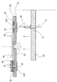
1 is a side view illustrating the overall configuration of the present invention.
Figure 2 is a plan view showing the configuration of the electric gear of the present invention.
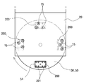
Figure 3 is an exemplary view of the workpiece processing state and the configuration of the spindle holder and jig of the present invention.
Figure 4 is an exemplary view of a machining state of another workpiece of the present invention and the configuration of the spindle holder and the jig.
Figure 5 is an illustration of the configuration and operation of the spindle holder and the turntable of the present invention.
Figure 6 is an illustration of another configuration of the turntable of the present invention.
When explaining the embodiment according to the configuration of the present invention in detail as follows.
The
The
The
The
At this time, the
In addition, the
And the lower side of the position where the
At this time, the
The
And the lower side of the
Here, the tool table 10 may be fixed and the
On the
In addition, the
In addition, the
And the
In this way, the
Here, the
The
In addition, the
In the present invention, in the construction of a tapping machine, a plurality of adjacent tap holes may be installed in a line to be processed to improve productivity.
10: tool post 11: electric box 12: motor
13: Electric gear 14: Universal joint 15: Spindle
20: spindle holder 21: pressing support 22: cushion
30: turntable 31: motor 32: airline
35: magnet chuck
50: jig 51: workpiece insertion hole 52: air hole
60: tab 70: cylinder 100: main body
200: Workpiece 201: Taphole
Claims (6)
A plurality of electric gears 13 are configured to rotate the electric box 11 so as to drive by the driving force of the single motor 12, it is connected to each of the electric gear 13 configured in the electric box 11 by a universal joint (14). A tool holder 10 constituting the spindle holder 20 formed by dividing the plurality of spindles 15 to be rotated into at least two places and formed into two or more groups;
A turntable 30 which is divided into at least three or more portions by an encoder so as to sequentially supply the workpiece 200 to each of the spindles 15 of the tool post 10 divided into two or more groups;
Process oil supply means for supplying the processing oil when the tab 60 mounted on the spindle 15 of the tool post 10 to process the workpiece 200;
The tool post 10 is configured to move up and down by the cylinder 70, and the turntable 30 is configured to supply the workpiece 200 to the position of the tab 60 beneath it, and to process the workpiece 200 Multi-tapping machine, characterized in that consisting of the main body and the processing oil supply means for supplying the processing oil.
The spindle holder 20 of the tool post 10 is configured to coincide with the tap hole 201 of the workpiece 200 to have a machining position divided into at least two locations so that the position of the tap hole 201 of the workpiece 200 is adjusted. Multi-tapping machine, characterized in that configured to change the position of the tap (60) to the position of the tap hole (201) of the workpiece (200) by changing the position of the spindle (15) by changing the spindle holder (20) every time.
The spindle holder 20 of the tool rest 10 has a pressing support 21 for fixing the workpiece 200 supported on the cushion 22 made of spring or rubber at the lower end of the machining position divided into at least two places. Multi-tapping machine, characterized in that the integral configuration.
The turntable 30, which is divided and rotated by an encoder so as to sequentially supply the workpiece 200 to each of the spindle 15 of the tool post 10, is divided into three groups, the workpiece 200 on the upper end thereof. It is configured to mount and set the mounting jig (50), to configure the magnet chuck 35 to suck the workpiece 200 seated on the jig (50), for leaving the workpiece 200 is finished tapping Multi-tapping machine, characterized in that the air supply line 32.
The jig 50 constitutes a workpiece insertion hole 51 having a tab guide hole for seating the workpiece 200 so as to supply the workpiece 200 to the position of the tab 60 formed on the spindle group of the tool post 10. Multi-tapping machine characterized by.
The jig 50 mounted on the turntable 30 constitutes an air hole 52 which ejects air from the bottom surface to the workpiece insertion hole 51 on which the workpiece 200 is mounted, thereby leaving the workpiece 200. Multi-tapping machine characterized by.
Priority Applications (1)
| Application Number | Priority Date | Filing Date | Title |
|---|---|---|---|
| KR1020100067186A KR20120006622A (en) | 2010-07-13 | 2010-07-13 | Multi-tapping machine |
Applications Claiming Priority (1)
| Application Number | Priority Date | Filing Date | Title |
|---|---|---|---|
| KR1020100067186A KR20120006622A (en) | 2010-07-13 | 2010-07-13 | Multi-tapping machine |
Publications (1)
| Publication Number | Publication Date |
|---|---|
| KR20120006622A true KR20120006622A (en) | 2012-01-19 |
Family
ID=45612229
Family Applications (1)
| Application Number | Title | Priority Date | Filing Date |
|---|---|---|---|
| KR1020100067186A KR20120006622A (en) | 2010-07-13 | 2010-07-13 | Multi-tapping machine |
Country Status (1)
| Country | Link |
|---|---|
| KR (1) | KR20120006622A (en) |
Cited By (12)
| Publication number | Priority date | Publication date | Assignee | Title |
|---|---|---|---|---|
| KR101347841B1 (en) * | 2012-04-13 | 2014-01-10 | (주)대륜하이테크 | Mold Press Tapping Appratus |
| CN104209603A (en) * | 2014-09-11 | 2014-12-17 | 江苏凌云恒晋汽车零部件有限公司 | Tapping clamp |
| CN105798403A (en) * | 2016-05-06 | 2016-07-27 | 常州市大备智能物联网科技有限公司 | Multi-size nut tapping machine |
| CN105834530A (en) * | 2016-05-10 | 2016-08-10 | 平湖市品耀机器自动化有限公司 | Full-automatic multi-head tapping machine |
| CN105880751A (en) * | 2016-05-10 | 2016-08-24 | 平湖市品耀机器自动化有限公司 | Multi-head tapping machine |
| CN105880754A (en) * | 2016-05-10 | 2016-08-24 | 平湖市品耀机器自动化有限公司 | Handpiece assembly of multi-head tapping machine |
| CN105904041A (en) * | 2016-05-10 | 2016-08-31 | 平湖市品耀机器自动化有限公司 | Full-automatic tapping unit |
| CN106466746A (en) * | 2016-05-10 | 2017-03-01 | 平湖市品耀机器自动化有限公司 | A kind of tapping machine |
| CN108284256A (en) * | 2018-03-19 | 2018-07-17 | 安徽理工大学 | A kind of anchor clipper automatic tapping machine |
| CN108723513A (en) * | 2018-06-21 | 2018-11-02 | 苏州润桐专利运营有限公司 | A kind of three-way connection threading apparatus |
| CN110052669A (en) * | 2019-05-22 | 2019-07-26 | 安徽法西欧汽车部件有限公司 | A kind of semi-automatic filter hush panel tapping device |
| KR102234281B1 (en) * | 2019-11-08 | 2021-03-31 | 주식회사 디피메탈 | Rotary type milling machine using magnet |
-
2010
- 2010-07-13 KR KR1020100067186A patent/KR20120006622A/en not_active Application Discontinuation
Cited By (14)
| Publication number | Priority date | Publication date | Assignee | Title |
|---|---|---|---|---|
| KR101347841B1 (en) * | 2012-04-13 | 2014-01-10 | (주)대륜하이테크 | Mold Press Tapping Appratus |
| CN104209603A (en) * | 2014-09-11 | 2014-12-17 | 江苏凌云恒晋汽车零部件有限公司 | Tapping clamp |
| CN105798403A (en) * | 2016-05-06 | 2016-07-27 | 常州市大备智能物联网科技有限公司 | Multi-size nut tapping machine |
| CN105904041A (en) * | 2016-05-10 | 2016-08-31 | 平湖市品耀机器自动化有限公司 | Full-automatic tapping unit |
| CN105880751A (en) * | 2016-05-10 | 2016-08-24 | 平湖市品耀机器自动化有限公司 | Multi-head tapping machine |
| CN105880754A (en) * | 2016-05-10 | 2016-08-24 | 平湖市品耀机器自动化有限公司 | Handpiece assembly of multi-head tapping machine |
| CN105834530A (en) * | 2016-05-10 | 2016-08-10 | 平湖市品耀机器自动化有限公司 | Full-automatic multi-head tapping machine |
| CN106466746A (en) * | 2016-05-10 | 2017-03-01 | 平湖市品耀机器自动化有限公司 | A kind of tapping machine |
| CN108284256A (en) * | 2018-03-19 | 2018-07-17 | 安徽理工大学 | A kind of anchor clipper automatic tapping machine |
| CN108284256B (en) * | 2018-03-19 | 2024-02-06 | 安徽理工大学 | Automatic tapping machine for anchorage clamping piece |
| CN108723513A (en) * | 2018-06-21 | 2018-11-02 | 苏州润桐专利运营有限公司 | A kind of three-way connection threading apparatus |
| CN110052669A (en) * | 2019-05-22 | 2019-07-26 | 安徽法西欧汽车部件有限公司 | A kind of semi-automatic filter hush panel tapping device |
| CN110052669B (en) * | 2019-05-22 | 2023-11-14 | 安徽法西欧汽车部件有限公司 | Tapping device for sealing plate of semi-automatic filter |
| KR102234281B1 (en) * | 2019-11-08 | 2021-03-31 | 주식회사 디피메탈 | Rotary type milling machine using magnet |
Similar Documents
| Publication | Publication Date | Title |
|---|---|---|
| KR20120006622A (en) | Multi-tapping machine | |
| CN102896561B (en) | Fully automatic numerical control drill cutter grinding machine | |
| DE102007045619B4 (en) | Device for fine machining of workpieces | |
| CN104625290A (en) | Cantilever type automatic tin soldering device | |
| KR101312152B1 (en) | Calliper bleed and feed complex manufacturing machine for automotive brake system | |
| CN208743742U (en) | Bearing outer ring oil filler point automatic drilling machine | |
| CN104907829A (en) | Numerical control horizontal type three-axis drilling and milling tapping machine | |
| KR100768940B1 (en) | Drilling machine for sheet plate of heat exchanger | |
| KR101326249B1 (en) | Hole Drilling Apparatus for Work Piece | |
| CN102029545A (en) | Press-elastic type automatic loading device | |
| CN202517335U (en) | Up and down rotational type multifunctional drilling machine | |
| KR101023150B1 (en) | Processing head for automatic deburring machine | |
| KR100957609B1 (en) | A exclusive processing facilities for v-groove | |
| KR20080108928A (en) | A combined processing facilities with movement independently | |
| CN205552015U (en) | All -round high -efficient deep -hole drilling machine | |
| KR101713439B1 (en) | Machining center for multi-spindle | |
| CN104043853A (en) | Numerical control drilling machine tool | |
| CN201596795U (en) | Multi-hole simultaneous processing device of motorcycle steering column connecting plate | |
| KR20200025029A (en) | Deburring apparatus for auto transmisson shift pipe | |
| KR200422052Y1 (en) | The unit which winds the cotton with automatic movement | |
| CN206200550U (en) | A kind of porous drilling and milling, boring equipment | |
| KR101806231B1 (en) | tap processing device | |
| CN105149954B (en) | Digital controlled drill for machining radial holes of shaft parts | |
| WO2021036438A1 (en) | Machining platform of box body holes | |
| KR100816637B1 (en) | Automatic works change device for machining center |
Legal Events
| Date | Code | Title | Description |
|---|---|---|---|
| A201 | Request for examination | ||
| E902 | Notification of reason for refusal | ||
| E601 | Decision to refuse application |