KR20080098396A - Led 드라이버 회로 - Google Patents
Led 드라이버 회로 Download PDFInfo
- Publication number
- KR20080098396A KR20080098396A KR1020087021117A KR20087021117A KR20080098396A KR 20080098396 A KR20080098396 A KR 20080098396A KR 1020087021117 A KR1020087021117 A KR 1020087021117A KR 20087021117 A KR20087021117 A KR 20087021117A KR 20080098396 A KR20080098396 A KR 20080098396A
- Authority
- KR
- South Korea
- Prior art keywords
- led
- comparator
- led driver
- driver circuit
- voltage
- Prior art date
- Legal status (The legal status is an assumption and is not a legal conclusion. Google has not performed a legal analysis and makes no representation as to the accuracy of the status listed.)
- Granted
Links
Images


Classifications
-
- H—ELECTRICITY
- H05—ELECTRIC TECHNIQUES NOT OTHERWISE PROVIDED FOR
- H05B—ELECTRIC HEATING; ELECTRIC LIGHT SOURCES NOT OTHERWISE PROVIDED FOR; CIRCUIT ARRANGEMENTS FOR ELECTRIC LIGHT SOURCES, IN GENERAL
- H05B45/00—Circuit arrangements for operating light-emitting diodes [LED]
- H05B45/30—Driver circuits
- H05B45/37—Converter circuits
-
- H—ELECTRICITY
- H05—ELECTRIC TECHNIQUES NOT OTHERWISE PROVIDED FOR
- H05B—ELECTRIC HEATING; ELECTRIC LIGHT SOURCES NOT OTHERWISE PROVIDED FOR; CIRCUIT ARRANGEMENTS FOR ELECTRIC LIGHT SOURCES, IN GENERAL
- H05B45/00—Circuit arrangements for operating light-emitting diodes [LED]
- H05B45/10—Controlling the intensity of the light
-
- H—ELECTRICITY
- H05—ELECTRIC TECHNIQUES NOT OTHERWISE PROVIDED FOR
- H05B—ELECTRIC HEATING; ELECTRIC LIGHT SOURCES NOT OTHERWISE PROVIDED FOR; CIRCUIT ARRANGEMENTS FOR ELECTRIC LIGHT SOURCES, IN GENERAL
- H05B45/00—Circuit arrangements for operating light-emitting diodes [LED]
- H05B45/30—Driver circuits
- H05B45/37—Converter circuits
- H05B45/3725—Switched mode power supply [SMPS]
- H05B45/375—Switched mode power supply [SMPS] using buck topology
-
- F—MECHANICAL ENGINEERING; LIGHTING; HEATING; WEAPONS; BLASTING
- F21—LIGHTING
- F21Y—INDEXING SCHEME ASSOCIATED WITH SUBCLASSES F21K, F21L, F21S and F21V, RELATING TO THE FORM OR THE KIND OF THE LIGHT SOURCES OR OF THE COLOUR OF THE LIGHT EMITTED
- F21Y2115/00—Light-generating elements of semiconductor light sources
- F21Y2115/10—Light-emitting diodes [LED]
-
- H—ELECTRICITY
- H05—ELECTRIC TECHNIQUES NOT OTHERWISE PROVIDED FOR
- H05B—ELECTRIC HEATING; ELECTRIC LIGHT SOURCES NOT OTHERWISE PROVIDED FOR; CIRCUIT ARRANGEMENTS FOR ELECTRIC LIGHT SOURCES, IN GENERAL
- H05B45/00—Circuit arrangements for operating light-emitting diodes [LED]
- H05B45/30—Driver circuits
- H05B45/37—Converter circuits
- H05B45/3725—Switched mode power supply [SMPS]
- H05B45/385—Switched mode power supply [SMPS] using flyback topology
Landscapes
- Circuit Arrangement For Electric Light Sources In General (AREA)
- Dc-Dc Converters (AREA)
- Led Devices (AREA)
- Electronic Switches (AREA)
Abstract
Description

Claims (6)
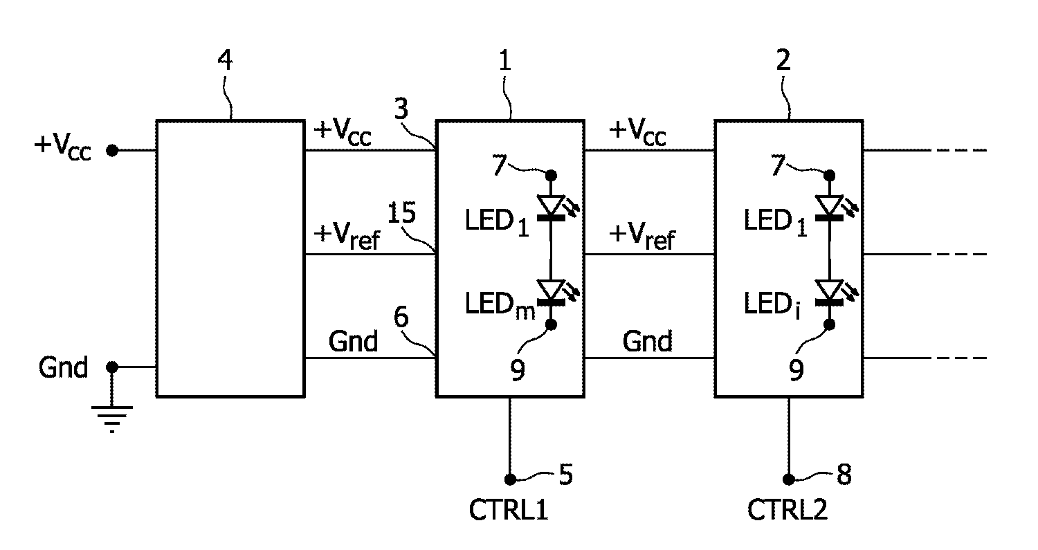
- LED 드라이버 회로(1)로서,공급 전압 입력 단자(3)와,제어 입력 단자(5)와,상기 LED 드라이버 회로를 적어도 하나의 LED에 연결하기 위한 제1 출력 단자(7) 및 제2 출력 단자(9)를 포함하고,다운 컨버팅 특징부(11)를 갖는 스위칭 모드 전원(switched-mode power supply; smps)은 상기 공급 전압 입력 단자(3)와 상기 제1 출력 단자(7) 간에 연결되어 있으며, 상기 컨버터(11)는 LED 전류를 조절하기 위해 히스테리시스 구성 비교기 회로(hysteresis configured comparator circuit; 13)에 의해 제어되며, 상기 비교기의 스위칭 레벨은 기준 단자(15)에서 수신되는 기준 전압(+Vref)에 의해 설정되는 LED 드라이버 회로.
- 제1항에 있어서,상기 제어 입력 단자(5)는, 상기 비교기 회로(13)의 출력을 활성화 또는 비활성화하는 스위치(17)에 연결되어 있는 LED 드라이버 회로.
- 제1항에 있어서,상기 제어 입력 단자(5)는, 상기 비교기 회로(13) 내의 분압기 네트워크에 영향을 끼치는 스위치(19)에 연결되어 있는 LED 드라이버 회로.
- 제1항 내지 제3항 중 어느 한 항에 있어서,션트 저항기(Rs)는 상기 비교기 회로(13)에 공급되는 대응 전압을 정하기 위해 LED 전류(ILED)를 수신하는 LED 드라이버 회로.
- 제4항에 있어서,상기 전압은 로우-패스 필터(23)를 통해 상기 비교기 회로에 공급되는 LED 드라이버 회로.
- 제1항 내지 제5항 중 어느 한 항에 있어서,상기 컨버터(11)는 (스텝) 다운 컨버터 또는 버크(buck) 컨버터인 LED 드라이버 회로.
Applications Claiming Priority (3)
| Application Number | Priority Date | Filing Date | Title |
|---|---|---|---|
| EP06101079 | 2006-01-31 | ||
| EP06101079.9 | 2006-01-31 | ||
| PCT/IB2007/050279 WO2007088505A1 (en) | 2006-01-31 | 2007-01-26 | Led driver circuit |
Publications (2)
| Publication Number | Publication Date |
|---|---|
| KR20080098396A true KR20080098396A (ko) | 2008-11-07 |
| KR101303362B1 KR101303362B1 (ko) | 2013-09-03 |
Family
ID=37905021
Family Applications (1)
| Application Number | Title | Priority Date | Filing Date |
|---|---|---|---|
| KR1020087021117A Active KR101303362B1 (ko) | 2006-01-31 | 2007-01-26 | Led 드라이버 회로 |
Country Status (7)
| Country | Link |
|---|---|
| US (1) | US8217587B2 (ko) |
| EP (1) | EP1982560A1 (ko) |
| JP (1) | JP5329235B2 (ko) |
| KR (1) | KR101303362B1 (ko) |
| CN (1) | CN101379879B (ko) |
| TW (1) | TWI434609B (ko) |
| WO (1) | WO2007088505A1 (ko) |
Families Citing this family (58)
| Publication number | Priority date | Publication date | Assignee | Title |
|---|---|---|---|---|
| US20050259424A1 (en) * | 2004-05-18 | 2005-11-24 | Zampini Thomas L Ii | Collimating and controlling light produced by light emitting diodes |
| US7766511B2 (en) * | 2006-04-24 | 2010-08-03 | Integrated Illumination Systems | LED light fixture |
| US7746300B2 (en) | 2006-05-05 | 2010-06-29 | Linear Technology Corporation | Circuit and methodology for supplying pulsed current to a load, such as a light emitting diode |
| US8324816B2 (en) * | 2006-10-18 | 2012-12-04 | Koa Corporation | LED driving circuit |
| US7729941B2 (en) | 2006-11-17 | 2010-06-01 | Integrated Illumination Systems, Inc. | Apparatus and method of using lighting systems to enhance brand recognition |
| WO2008068705A1 (en) * | 2006-12-06 | 2008-06-12 | Nxp B.V. | Controlled voltage source for led drivers |
| US8013538B2 (en) | 2007-01-26 | 2011-09-06 | Integrated Illumination Systems, Inc. | TRI-light |
| CN101772798B (zh) * | 2007-08-02 | 2012-10-31 | 皇家飞利浦电子股份有限公司 | 光输出装置 |
| US8742686B2 (en) * | 2007-09-24 | 2014-06-03 | Integrated Illumination Systems, Inc. | Systems and methods for providing an OEM level networked lighting system |
| DE102007047725A1 (de) * | 2007-10-05 | 2009-04-09 | Texas Instruments Deutschland Gmbh | Direkte Stromlieferung mit einem induktiven Abwärts- oder Aufwärtswandler zur Anwendung auf LED-Treiber |
| EP2066149A3 (de) * | 2007-11-27 | 2009-08-19 | Stefan Ruppel | LED-Flachleuchte mit wärmeableitender Platine insbesondere für Möbel |
| US8255487B2 (en) * | 2008-05-16 | 2012-08-28 | Integrated Illumination Systems, Inc. | Systems and methods for communicating in a lighting network |
| JP2010080524A (ja) * | 2008-09-24 | 2010-04-08 | Sanyo Electric Co Ltd | 発光素子駆動制御回路 |
| DE102009007503A1 (de) * | 2009-02-05 | 2010-08-12 | E:Cue Control Gmbh | Beleuchtungsanordnung |
| US20120039045A1 (en) * | 2009-04-22 | 2012-02-16 | Mitsubishi Electric Corporation | Power module and method for detecting insulation degradation thereof |
| US8585245B2 (en) | 2009-04-23 | 2013-11-19 | Integrated Illumination Systems, Inc. | Systems and methods for sealing a lighting fixture |
| WO2011001369A2 (en) | 2009-07-03 | 2011-01-06 | Koninklijke Philips Electronics N.V. | Low cost power supply circuit and method |
| US8525434B2 (en) * | 2009-10-07 | 2013-09-03 | Marvell World Trade Ltd. | Method and apparatus for power driving |
| TWI411354B (zh) * | 2009-11-03 | 2013-10-01 | Himax Analogic Inc | 開關電路及發光二極體電路 |
| ITPR20100006A1 (it) * | 2010-01-29 | 2011-07-30 | Light & Colour Engineering S R L | Dispositivo di illuminazione. |
| WO2011126374A2 (en) * | 2010-04-09 | 2011-10-13 | Eldolab Holding B.V. | Driver system for driving a plurality of led's |
| IT1399217B1 (it) * | 2010-04-09 | 2013-04-11 | Artemide Spa | Apparecchio di illuminazione a led con regolazione dell'intensita' di illuminazione |
| US8450936B1 (en) | 2010-05-13 | 2013-05-28 | Whelen Engineering Company, Inc. | Dual range power supply |
| TWI422279B (zh) * | 2010-05-28 | 2014-01-01 | Himax Analogic Inc | 發光二極體驅動電路 |
| US8525437B2 (en) | 2010-09-16 | 2013-09-03 | Samsung Electro-Mechanics Co., Ltd. | Device for controlling current of LED |
| US9491822B2 (en) * | 2010-10-01 | 2016-11-08 | Intersil Americas LLC | LED driver with adaptive dynamic headroom voltage control |
| IT1403159B1 (it) * | 2010-12-02 | 2013-10-04 | Osram Spa | Dispositivo convertitore. |
| US9066381B2 (en) | 2011-03-16 | 2015-06-23 | Integrated Illumination Systems, Inc. | System and method for low level dimming |
| US9967940B2 (en) | 2011-05-05 | 2018-05-08 | Integrated Illumination Systems, Inc. | Systems and methods for active thermal management |
| US8188671B2 (en) * | 2011-06-07 | 2012-05-29 | Switch Bulb Company, Inc. | Power factor control for an LED bulb driver circuit |
| US20150237700A1 (en) | 2011-07-26 | 2015-08-20 | Hunter Industries, Inc. | Systems and methods to control color and brightness of lighting devices |
| US11917740B2 (en) | 2011-07-26 | 2024-02-27 | Hunter Industries, Inc. | Systems and methods for providing power and data to devices |
| US8710770B2 (en) | 2011-07-26 | 2014-04-29 | Hunter Industries, Inc. | Systems and methods for providing power and data to lighting devices |
| US9609720B2 (en) | 2011-07-26 | 2017-03-28 | Hunter Industries, Inc. | Systems and methods for providing power and data to lighting devices |
| US10874003B2 (en) | 2011-07-26 | 2020-12-22 | Hunter Industries, Inc. | Systems and methods for providing power and data to devices |
| US9521725B2 (en) | 2011-07-26 | 2016-12-13 | Hunter Industries, Inc. | Systems and methods for providing power and data to lighting devices |
| US8604699B2 (en) * | 2011-12-07 | 2013-12-10 | Atmel Corporation | Self-power for device driver |
| EP2798916B1 (en) * | 2011-12-28 | 2017-05-03 | OSRAM GmbH | Converter device |
| US8894437B2 (en) | 2012-07-19 | 2014-11-25 | Integrated Illumination Systems, Inc. | Systems and methods for connector enabling vertical removal |
| US9379578B2 (en) | 2012-11-19 | 2016-06-28 | Integrated Illumination Systems, Inc. | Systems and methods for multi-state power management |
| DE102012111317B4 (de) | 2012-11-23 | 2021-07-22 | HELLA GmbH & Co. KGaA | Schaltungsanordnung mit einem Abwärtswandler |
| US9420665B2 (en) | 2012-12-28 | 2016-08-16 | Integration Illumination Systems, Inc. | Systems and methods for continuous adjustment of reference signal to control chip |
| US9485814B2 (en) * | 2013-01-04 | 2016-11-01 | Integrated Illumination Systems, Inc. | Systems and methods for a hysteresis based driver using a LED as a voltage reference |
| CN103209531B (zh) * | 2013-04-28 | 2014-11-26 | 宁波赛耐比光电有限公司 | Led调光控制电路 |
| CN104470060B (zh) * | 2014-10-20 | 2017-09-15 | 深圳市华星光电技术有限公司 | 模拟调光转换电路及显示装置 |
| DE102015208078A1 (de) * | 2015-04-30 | 2016-11-03 | Osram Gmbh | Schaltungsanordnung und Verfahren zur Verringerung der Lichtmodulation von mindestens einer an einer Spannung betriebenen Lichtquelle |
| US10918030B2 (en) | 2015-05-26 | 2021-02-16 | Hunter Industries, Inc. | Decoder systems and methods for irrigation control |
| US10228711B2 (en) | 2015-05-26 | 2019-03-12 | Hunter Industries, Inc. | Decoder systems and methods for irrigation control |
| US10030844B2 (en) | 2015-05-29 | 2018-07-24 | Integrated Illumination Systems, Inc. | Systems, methods and apparatus for illumination using asymmetrical optics |
| US10060599B2 (en) | 2015-05-29 | 2018-08-28 | Integrated Illumination Systems, Inc. | Systems, methods and apparatus for programmable light fixtures |
| US10117298B1 (en) | 2017-04-11 | 2018-10-30 | Seasons 4, Inc. | Curtain-configured light strings |
| US9986610B1 (en) | 2017-04-11 | 2018-05-29 | Seasons 4, Inc. | Long-chain-tolerant decorative strings of independently illumination controllable LEDs |
| US10337710B2 (en) | 2017-04-11 | 2019-07-02 | Seasons 4, Inc. | Tree with integrated lighting elements receiving power and control data over common conductors |
| US10225916B2 (en) | 2017-04-11 | 2019-03-05 | Seasons 4, Inc. | Data/power controller for translation between light control protocols |
| US10483850B1 (en) | 2017-09-18 | 2019-11-19 | Ecosense Lighting Inc. | Universal input-voltage-compatible switched-mode power supply |
| US10801714B1 (en) | 2019-10-03 | 2020-10-13 | CarJamz, Inc. | Lighting device |
| US12416908B2 (en) | 2022-12-29 | 2025-09-16 | Integrated Illumination Systems, Inc. | Systems and methods for manufacturing light fixtures |
| US12297996B2 (en) | 2023-02-16 | 2025-05-13 | Integrated Illumination Systems, Inc. | Cove light fixture with hidden integrated air return |
Family Cites Families (21)
| Publication number | Priority date | Publication date | Assignee | Title |
|---|---|---|---|---|
| US4504776A (en) * | 1980-11-12 | 1985-03-12 | Bei Electronics, Inc. | Power saving regulated light emitting diode circuit |
| JPH0594151A (ja) * | 1991-08-08 | 1993-04-16 | Seiwa Denki Kk | Led点灯回路 |
| JP3457763B2 (ja) * | 1995-04-13 | 2003-10-20 | アルプス電気株式会社 | 発光素子駆動回路 |
| FI106770B (fi) * | 1999-01-22 | 2001-03-30 | Nokia Mobile Phones Ltd | Valaiseva elektroninen laite ja valaisumenetelmä |
| US6618031B1 (en) * | 1999-02-26 | 2003-09-09 | Three-Five Systems, Inc. | Method and apparatus for independent control of brightness and color balance in display and illumination systems |
| US6404265B1 (en) * | 1999-08-13 | 2002-06-11 | York International Corporation | Highly efficient driver circuit for a solid state switch |
| JP3445540B2 (ja) * | 1999-11-16 | 2003-09-08 | 常盤電業株式会社 | 電源回路 |
| US6396217B1 (en) * | 2000-12-22 | 2002-05-28 | Visteon Global Technologies, Inc. | Brightness offset error reduction system and method for a display device |
| US7071762B2 (en) * | 2001-01-31 | 2006-07-04 | Koninklijke Philips Electronics N.V. | Supply assembly for a led lighting module |
| DE10225670A1 (de) | 2002-06-10 | 2003-12-24 | Patent Treuhand Ges Fuer Elektrische Gluehlampen Mbh | Ansteuerschaltung für mindestens einen LED-Strang |
| JP4148746B2 (ja) * | 2002-10-08 | 2008-09-10 | 株式会社小糸製作所 | 点灯回路 |
| WO2004100614A1 (en) * | 2003-05-07 | 2004-11-18 | Koninklijke Philips Electronics N.V. | Current control method and circuit for light emitting diodes |
| JP2005005112A (ja) * | 2003-06-11 | 2005-01-06 | Yazaki Corp | Led駆動回路 |
| CN2631184Y (zh) * | 2003-07-17 | 2004-08-04 | 上海精密科学仪器有限公司 | 发光二极管驱动电路 |
| JP4052998B2 (ja) * | 2003-11-25 | 2008-02-27 | シャープ株式会社 | 電源回路及びそれを用いた電子機器 |
| DK3589081T3 (da) * | 2004-03-15 | 2024-03-18 | Signify North America Corp | Effektstyringfremgangsmåder og -apparat |
| TWI236165B (en) * | 2004-07-30 | 2005-07-11 | Au Optronics Corp | Driving device for light emitted diode string |
| US7675487B2 (en) | 2005-07-15 | 2010-03-09 | Honeywell International, Inc. | Simplified light-emitting diode (LED) hysteretic current controller |
| US7259525B2 (en) * | 2005-11-03 | 2007-08-21 | System General Corporation | High efficiency switching LED driver |
| US7602305B2 (en) * | 2005-11-15 | 2009-10-13 | Skyline Products, Inc. | Feedback circuit for a display sign and method |
| US20070114951A1 (en) * | 2005-11-22 | 2007-05-24 | Tsen Chia-Hung | Drive circuit for a light emitting diode array |
-
2007
- 2007-01-26 KR KR1020087021117A patent/KR101303362B1/ko active Active
- 2007-01-26 WO PCT/IB2007/050279 patent/WO2007088505A1/en not_active Ceased
- 2007-01-26 US US12/162,372 patent/US8217587B2/en active Active
- 2007-01-26 CN CN2007800041739A patent/CN101379879B/zh active Active
- 2007-01-26 EP EP07705719A patent/EP1982560A1/en not_active Ceased
- 2007-01-26 JP JP2008551939A patent/JP5329235B2/ja active Active
- 2007-01-29 TW TW096103240A patent/TWI434609B/zh active
Also Published As
| Publication number | Publication date |
|---|---|
| JP5329235B2 (ja) | 2013-10-30 |
| US8217587B2 (en) | 2012-07-10 |
| KR101303362B1 (ko) | 2013-09-03 |
| EP1982560A1 (en) | 2008-10-22 |
| JP2009525595A (ja) | 2009-07-09 |
| TWI434609B (zh) | 2014-04-11 |
| US20090021182A1 (en) | 2009-01-22 |
| TW200803618A (en) | 2008-01-01 |
| WO2007088505A1 (en) | 2007-08-09 |
| CN101379879B (zh) | 2011-08-17 |
| CN101379879A (zh) | 2009-03-04 |
Similar Documents
| Publication | Publication Date | Title |
|---|---|---|
| KR101303362B1 (ko) | Led 드라이버 회로 | |
| US9699844B2 (en) | Multichannel constant current LED driving circuit, driving method and LED driving power | |
| KR101835255B1 (ko) | 공통 스위치 제어 신호를 이용하는 led 드라이버에 대한 부스트 덴 플로팅 벅 모드 컨버터 | |
| US8093822B2 (en) | LED driver and control method thereof | |
| KR100867551B1 (ko) | Led 어레이 구동 장치 | |
| US7595622B1 (en) | System and method for providing a sample and hold circuit for maintaining an output voltage of a constant current source circuit when a feedback loop is disconnected | |
| US9648677B2 (en) | LED driving circuit and method using single inductor | |
| US20170347417A1 (en) | Control circuit, control method and switching power supply thereof | |
| KR102050173B1 (ko) | 스위칭 컨버터 및 그 제어 회로, 그것을 사용한 조명 장치, 전자 기기 | |
| KR20120038466A (ko) | 저가 전원 회로 및 방법 | |
| US20190159308A1 (en) | Line ripple reducer | |
| US11743990B2 (en) | Balance control for 2-channel CCT dimming | |
| JP2019061854A (ja) | 点灯システム、照明装置、照明制御システム、及びプログラム | |
| US9825528B2 (en) | Compensating for voltage changes in driver circuits | |
| US10461633B2 (en) | DC-to-DC drivers with high resolution dimming | |
| KR20130027854A (ko) | 백라이트 유닛 | |
| US20120119671A1 (en) | Apparatus and method for circuit configuration for powering light emitting diodes | |
| EP2897272B1 (en) | Method and converter for supplying current to series connection of LEDs | |
| HK40063609A (en) | Method and devices for regulating the output voltage of a voltage regulator | |
| HK40063609B (zh) | 用於调节电压调节器的输出电压的方法和装置 |
Legal Events
| Date | Code | Title | Description |
|---|---|---|---|
| PA0105 | International application |
St.27 status event code: A-0-1-A10-A15-nap-PA0105 |
|
| E13-X000 | Pre-grant limitation requested |
St.27 status event code: A-2-3-E10-E13-lim-X000 |
|
| P11-X000 | Amendment of application requested |
St.27 status event code: A-2-2-P10-P11-nap-X000 |
|
| P13-X000 | Application amended |
St.27 status event code: A-2-2-P10-P13-nap-X000 |
|
| PG1501 | Laying open of application |
St.27 status event code: A-1-1-Q10-Q12-nap-PG1501 |
|
| A201 | Request for examination | ||
| PA0201 | Request for examination |
St.27 status event code: A-1-2-D10-D11-exm-PA0201 |
|
| E902 | Notification of reason for refusal | ||
| PE0902 | Notice of grounds for rejection |
St.27 status event code: A-1-2-D10-D21-exm-PE0902 |
|
| P11-X000 | Amendment of application requested |
St.27 status event code: A-2-2-P10-P11-nap-X000 |
|
| P13-X000 | Application amended |
St.27 status event code: A-2-2-P10-P13-nap-X000 |
|
| R18-X000 | Changes to party contact information recorded |
St.27 status event code: A-3-3-R10-R18-oth-X000 |
|
| E701 | Decision to grant or registration of patent right | ||
| PE0701 | Decision of registration |
St.27 status event code: A-1-2-D10-D22-exm-PE0701 |
|
| GRNT | Written decision to grant | ||
| PR0701 | Registration of establishment |
St.27 status event code: A-2-4-F10-F11-exm-PR0701 |
|
| PR1002 | Payment of registration fee |
St.27 status event code: A-2-2-U10-U12-oth-PR1002 Fee payment year number: 1 |
|
| PG1601 | Publication of registration |
St.27 status event code: A-4-4-Q10-Q13-nap-PG1601 |
|
| PN2301 | Change of applicant |
St.27 status event code: A-5-5-R10-R13-asn-PN2301 St.27 status event code: A-5-5-R10-R11-asn-PN2301 |
|
| FPAY | Annual fee payment |
Payment date: 20160819 Year of fee payment: 4 |
|
| PR1001 | Payment of annual fee |
St.27 status event code: A-4-4-U10-U11-oth-PR1001 Fee payment year number: 4 |
|
| P22-X000 | Classification modified |
St.27 status event code: A-4-4-P10-P22-nap-X000 |
|
| PN2301 | Change of applicant |
St.27 status event code: A-5-5-R10-R11-asn-PN2301 |
|
| PN2301 | Change of applicant |
St.27 status event code: A-5-5-R10-R11-asn-PN2301 |
|
| PN2301 | Change of applicant |
St.27 status event code: A-5-5-R10-R14-asn-PN2301 |
|
| FPAY | Annual fee payment |
Payment date: 20170822 Year of fee payment: 5 |
|
| PR1001 | Payment of annual fee |
St.27 status event code: A-4-4-U10-U11-oth-PR1001 Fee payment year number: 5 |
|
| FPAY | Annual fee payment |
Payment date: 20180822 Year of fee payment: 6 |
|
| PR1001 | Payment of annual fee |
St.27 status event code: A-4-4-U10-U11-oth-PR1001 Fee payment year number: 6 |
|
| P22-X000 | Classification modified |
St.27 status event code: A-4-4-P10-P22-nap-X000 |
|
| R18-X000 | Changes to party contact information recorded |
St.27 status event code: A-5-5-R10-R18-oth-X000 |
|
| FPAY | Annual fee payment |
Payment date: 20190821 Year of fee payment: 7 |
|
| PR1001 | Payment of annual fee |
St.27 status event code: A-4-4-U10-U11-oth-PR1001 Fee payment year number: 7 |
|
| P22-X000 | Classification modified |
St.27 status event code: A-4-4-P10-P22-nap-X000 |
|
| P22-X000 | Classification modified |
St.27 status event code: A-4-4-P10-P22-nap-X000 |
|
| PR1001 | Payment of annual fee |
St.27 status event code: A-4-4-U10-U11-oth-PR1001 Fee payment year number: 8 |
|
| PR1001 | Payment of annual fee |
St.27 status event code: A-4-4-U10-U11-oth-PR1001 Fee payment year number: 9 |
|
| R18-X000 | Changes to party contact information recorded |
St.27 status event code: A-5-5-R10-R18-oth-X000 |
|
| PR1001 | Payment of annual fee |
St.27 status event code: A-4-4-U10-U11-oth-PR1001 Fee payment year number: 10 |
|
| PR1001 | Payment of annual fee |
St.27 status event code: A-4-4-U10-U11-oth-PR1001 Fee payment year number: 11 |
|
| PR1001 | Payment of annual fee |
St.27 status event code: A-4-4-U10-U11-oth-PR1001 Fee payment year number: 12 |
|
| PR1001 | Payment of annual fee |
St.27 status event code: A-4-4-U10-U11-oth-PR1001 Fee payment year number: 13 |
|
| U11 | Full renewal or maintenance fee paid |
Free format text: ST27 STATUS EVENT CODE: A-4-4-U10-U11-OTH-PR1001 (AS PROVIDED BY THE NATIONAL OFFICE) Year of fee payment: 13 |