KR20080098396A - LED driver circuit - Google Patents
LED driver circuit Download PDFInfo
- Publication number
- KR20080098396A KR20080098396A KR1020087021117A KR20087021117A KR20080098396A KR 20080098396 A KR20080098396 A KR 20080098396A KR 1020087021117 A KR1020087021117 A KR 1020087021117A KR 20087021117 A KR20087021117 A KR 20087021117A KR 20080098396 A KR20080098396 A KR 20080098396A
- Authority
- KR
- South Korea
- Prior art keywords
- led
- comparator
- led driver
- driver circuit
- voltage
- Prior art date
- Legal status (The legal status is an assumption and is not a legal conclusion. Google has not performed a legal analysis and makes no representation as to the accuracy of the status listed.)
- Granted
Links
Images


Classifications
-
- H—ELECTRICITY
- H05—ELECTRIC TECHNIQUES NOT OTHERWISE PROVIDED FOR
- H05B—ELECTRIC HEATING; ELECTRIC LIGHT SOURCES NOT OTHERWISE PROVIDED FOR; CIRCUIT ARRANGEMENTS FOR ELECTRIC LIGHT SOURCES, IN GENERAL
- H05B45/00—Circuit arrangements for operating light-emitting diodes [LED]
- H05B45/30—Driver circuits
- H05B45/37—Converter circuits
-
- H—ELECTRICITY
- H05—ELECTRIC TECHNIQUES NOT OTHERWISE PROVIDED FOR
- H05B—ELECTRIC HEATING; ELECTRIC LIGHT SOURCES NOT OTHERWISE PROVIDED FOR; CIRCUIT ARRANGEMENTS FOR ELECTRIC LIGHT SOURCES, IN GENERAL
- H05B45/00—Circuit arrangements for operating light-emitting diodes [LED]
- H05B45/10—Controlling the intensity of the light
-
- H—ELECTRICITY
- H05—ELECTRIC TECHNIQUES NOT OTHERWISE PROVIDED FOR
- H05B—ELECTRIC HEATING; ELECTRIC LIGHT SOURCES NOT OTHERWISE PROVIDED FOR; CIRCUIT ARRANGEMENTS FOR ELECTRIC LIGHT SOURCES, IN GENERAL
- H05B45/00—Circuit arrangements for operating light-emitting diodes [LED]
- H05B45/30—Driver circuits
- H05B45/37—Converter circuits
- H05B45/3725—Switched mode power supply [SMPS]
- H05B45/375—Switched mode power supply [SMPS] using buck topology
-
- F—MECHANICAL ENGINEERING; LIGHTING; HEATING; WEAPONS; BLASTING
- F21—LIGHTING
- F21Y—INDEXING SCHEME ASSOCIATED WITH SUBCLASSES F21K, F21L, F21S and F21V, RELATING TO THE FORM OR THE KIND OF THE LIGHT SOURCES OR OF THE COLOUR OF THE LIGHT EMITTED
- F21Y2115/00—Light-generating elements of semiconductor light sources
- F21Y2115/10—Light-emitting diodes [LED]
-
- H—ELECTRICITY
- H05—ELECTRIC TECHNIQUES NOT OTHERWISE PROVIDED FOR
- H05B—ELECTRIC HEATING; ELECTRIC LIGHT SOURCES NOT OTHERWISE PROVIDED FOR; CIRCUIT ARRANGEMENTS FOR ELECTRIC LIGHT SOURCES, IN GENERAL
- H05B45/00—Circuit arrangements for operating light-emitting diodes [LED]
- H05B45/30—Driver circuits
- H05B45/37—Converter circuits
- H05B45/3725—Switched mode power supply [SMPS]
- H05B45/385—Switched mode power supply [SMPS] using flyback topology
Landscapes
- Circuit Arrangement For Electric Light Sources In General (AREA)
- Dc-Dc Converters (AREA)
- Led Devices (AREA)
- Electronic Switches (AREA)
Abstract
본 발명은, 비교기(31)에 의해 제어되는 다운 컨버팅 특징부(11)를 갖는 스위칭 모드 전원(smps)을 포함하는 포함하는 저 비용 LED 드라이버 모듈에 관한 것이다. 이 비교기는 히스테리시스로 구성되며, LED 전류 내의 맥류와 과도 전류를 줄이고, 이 모듈은 비싸지 않은 비싼 표준 컴포넌트들로 이루어질 수 있다.The present invention relates to a low cost LED driver module comprising a switched mode power supply (smps) having a down converting feature 11 controlled by a comparator 31. The comparator consists of hysteresis, reducing the pulses and transients in the LED current, and the module can be made of standard components that are not expensive.
Description
본 발명은 LED(발광 다이오드) 드라이버 회로에 관한 것으로서, 이 LED 드라이버 회로는 공급 전압 입력 단자, 제어 입력 단자, 및 드라이버 회로를 적어도 하나의 LED에 연결하기 위한 제1 출력 단자와 제2 출력 단자를 포함한다.BACKGROUND OF THE
이러한 LED 드라이버 회로는, 예를 들어, 미국 특허공개번호 US 2003/0227265 A1에 개시되어 있다. 이러한 LED 드라이버 회로는 일반적으로 매우 유연성있고 정밀할 수 있는 전용 LED 드라이버 집적 회로(IC)로 만들어진다.Such LED driver circuits are disclosed, for example, in US Patent Publication No. US 2003/0227265 A1. These LED driver circuits are typically made of dedicated LED driver integrated circuits (ICs) that can be very flexible and precise.
그러나, 이러한 IC는, 일반적으로 상당히 비싸서, 다른 조명 컨셉트에 비하여 정밀도는 양호하나 LED 조명 장치의 경쟁력은 약화시킨다.However, such ICs are generally quite expensive, resulting in good precision compared to other lighting concepts but weakening the competitiveness of LED lighting devices.
따라서, 본 발명의 목적은, 비용은 덜 들지만 여전히 매우 정밀한 전술한 종류의 LED 드라이버 회로를 제공하는 것이다. It is therefore an object of the present invention to provide an LED driver circuit of the kind described above which is less expensive but still very precise.
이 목적은 청구항 제1항에서 정의한 바와 같은 LED 드라이버 회로에 의해 달성된다.This object is achieved by an LED driver circuit as defined in
구체적으로, LED 드라이버는, 공급 입력 단자와 제1 출력 단자 간에 연결된 다운 컨버팅 특징부를 갖는 스위칭 모드 전원(switched-mode power supply; smps)을 포함하며, 이 전원(smps)은 LED 전류를 조절하기 위해 히스테리시스 구성 비교기 회로(hysteresis-configured comparator circuit)에 의해 제어되며, 이 비교기의 스위칭 레벨은 기준 단자에서 수신되는 기준 전압에 의해 설정된다. 이러한 LED 드라이버는, 수십년동안 이용가능해 왔던 간단한 표준 컴포넌트만을 이용하여 얻을 수 있으며, 이에 따라 저 비용으로 얻어질 수 있다. 게다가, 다수의 이러한 LED 드라이버는 동일한 기준 전압을 공유할 수 있으며, 이것은 LED 드라이버를 보다 비용 효율적으로 만든다. Specifically, the LED driver includes a switched-mode power supply (smps) having a down-converting feature connected between the supply input terminal and the first output terminal, which power source for regulating the LED current. Controlled by a hysteresis-configured comparator circuit, the switching level of the comparator is set by a reference voltage received at the reference terminal. Such LED drivers can be obtained using only simple standard components that have been available for decades, and thus can be obtained at low cost. In addition, many of these LED drivers can share the same reference voltage, which makes the LED drivers more cost effective.
제어 입력 단자는, 비교기 회로의 출력을 활성화 또는 비활성화하는 스위치에 연결될 수 있다. 이것은 LED 출력의 정밀한 PWM 제어를 달성하는 데 있어서 효율적인 방식이다. The control input terminal can be connected to a switch that activates or deactivates the output of the comparator circuit. This is an efficient way to achieve precise PWM control of the LED output.
다른 방안으로, 제어 입력 단자는 비교기 회로 내의 분압기 네트워크에 영향을 끼치는 스위치에 연결될 수 있다. 이것은, 제한된 개수의 출력 레벨만이 필요한 경우 LED 드라이버를 덜 복잡하게 제어하는 방식을 제공한다.Alternatively, the control input terminal can be connected to a switch that affects the voltage divider network in the comparator circuit. This provides a less complex way to control the LED driver when only a limited number of output levels are needed.
션트 저항기는, 비교기 회로에 공급되는 대응 전압을 정하기 위해 LED 전류를 수신할 수 있다. 이것은 간단한 피드백 장치를 제공한다. 이 대응 전압은 로우-패스 필터를 통해 비교기 회로에 공급될 수 있다. 이것은 피드백 장치가 스위칭 잡음에 의해 영향을 받지 않게 한다.The shunt resistor can receive the LED current to determine the corresponding voltage supplied to the comparator circuit. This provides a simple feedback device. This corresponding voltage can be supplied to the comparator circuit through a low-pass filter. This ensures that the feedback device is not affected by switching noise.
다운 컨버팅 특징부를 갖는 스위칭 모드 전원(smps)은 다운 컨버터, 스텝다운 컨버터 또는 버크(buck) 컨버터로서 당해 기술에 알려진 컨버터일 수 있다.Switched mode power supplies (smps) with down converting features may be converters known in the art as down converters, step down converters or buck converters.
본 발명의 이러한 양태 및 다른 양태는 이하에서 설명하는 실시예들을 참조할 때 명백 및 자명할 것이다.These and other aspects of the invention will be apparent and apparent upon reference to the embodiments set forth below.
도 1은 LED 드라이버 회로들의 세트를 개략적으로 도시한다.1 schematically illustrates a set of LED driver circuits.
도 2는 본 발명의 일 실시예에 따른 LED 드라이버 회로를 도시한다.2 shows an LED driver circuit according to an embodiment of the present invention.
도 3은 다른 일 실시예에서의 LED 드라이버 회로의 상세를 도시한다.3 shows details of an LED driver circuit in another embodiment.
도 1은 공통 기준 블록(4)에 연결된 2개의 LED 드라이버 회로(1, 2)의 세트를 개략적으로 도시한다. 그러나, 이 장치는 실질적으로 임의의 개수의 LED 드라이버 회로를 포함하도록 가변적이다. 따라서, 예를 들어, RGB(적색-녹색-청색) 장치를 위한 3개의 드라이버 회로 또는 RGBA(적색-녹색-청색-황색) 장치를 위한 4개의 드라이버 회로를 고려할 수 있다. 이러한 장치 내의 LED들의 스트링 또는 각 LED의 광 흐름을 제어함으로써, 실질적으로 어떠한 색도 생성될 수 있다. 물론, 예를 들어, CMY(cyan-magenta-yellow)와 같은 다른 다색 장치도 가능하다. 예를 들어, 하나의 장치 내에 많은 RGB 유닛들을 제공할 수도 있다.1 schematically shows a set of two
공통 기준 블록은 공급 전압(+VCC), 기준 전압(+Vref), 접지 전압(Gnd)을 출력하도록 구성된다. 기준 전압(+Vref)은, 예를 들어, TL431과 같은 대역폭 기준 기반 전압 조절기(bandgap reference based voltage regulator)를 이용하여 제공될 수 있다.The common reference block is configured to output a supply voltage (+ V CC ), a reference voltage (+ V ref ), and a ground voltage (Gnd). The reference voltage (+ V ref ) may be provided using a bandwidth reference based voltage regulator such as, for example, TL431.
드라이버 회로들의 각각은, 공급 전압(+VCC)이 입력되는 공급 단자(3), 기준 전압(+Vref)을 수신하는 기준 단자(15), 및 접지 단자(6)를 포함한다. 각 드라이버 회로(1, 2)들은 제어 단자(5, 8)들을 더 포함하고, 이 제어 단자들은 제어 신호들(CTRL1, CTRL2)을 각각 수신한다. 이 제어 신호들은 각 드라이버 회로에 연결된 LED들로부터 출력되는 광 흐름을 제어한다.Each of the driver circuits includes a
드라이버 회로들의 각각은 하나의 LED 또는 직렬로 연결된 다수의 LED를 구동할 수 있다. 직렬로 연결된 다수의 다이오드가 사용된다면, 이들의 전체 전압 강하는 공급 전압(+VCC)보다 작아야 한다.Each of the driver circuits can drive one LED or multiple LEDs connected in series. If multiple diodes in series are used, their total voltage drop must be less than the supply voltage (+ V CC ).
도시한 바와 같이, 기준 전압 단자 뿐만 아니라 공급 전압 단자 및 접지 단자도, 예를 들어, RGB 유닛과 같은 다수의 후속 유닛에 데이지-체이닝(daisy-chained) 될 수 있다.As shown, not only the reference voltage terminal, but also the supply voltage terminal and the ground terminal can be daisy-chained to a number of subsequent units such as, for example, an RGB unit.
도 2는 본 발명의 일 실시예에 따른 LED 드라이버 회로(1)를 도시한다. 이 회로는 제1 출력 단자(7)와 제2 출력 단자(9)를 구비하며, 2개의 LED(8)가 이 출력 단자들 간에 직렬로 연결되어 있다.2 shows an
제1 출력 단자(7)는 다운 컨버팅 특징부(11)를 갖는 스위칭 모드 전원(smps)을 통해 공급 입력 단자(3)에 연결되며, 이 경우 그 다운 컨버팅 특징부는 소위 버크 컨버터 또는 (스텝) 다운 컨버터이다. 이 컨버터는 p-MOSFET과 같은 스위치(27)에 직렬로 연결된 인덕터(25)를 포함한다. 이 스위치는 인덕터를 통한 전류를 램프-업(ramp-up) 및 램프-다운하게 만들며, 프리휠(free-wheel) 다이오드(29)는 스위치가 스위칭 오프로 될 때 인덕터 전류가 계속해서 흐를 수 있게 한다. 물 론, 본 발명의 LED 드라이버에서, 예를 들어, 플라이백(flyback) 컨버터와 같은 다운 컨버팅 특징부를 갖는 다른 스위칭 모드 전원(smps) 토폴로지를 이용할 수도 있다.The
제2 출력 단자(9)는 션트 저항기(Rs)를 통해 접지된다. 션트 저항기를 통한 전압 강하는, LED 드라이버 회로에 의해 급전되는 LED들을 통해 공급되는 전류(ILED)의 측정량에 대응된다.The
smps(11)는 히스테리시스 구성 비교기 회로(hysteresis configured comparator circuit; 13)에 의해 제어된다. 이 회로는 비교기(31)를 포함하고, 이 비교기의 반전 입력(-)은 로우-패스 필터(23)를 통해 션트 저항기(Rs)로부터 LED 전류 측정값을 수신한다. 비교기(31)의 비반전 입력(+)은, 3개의 저항기(Rx, Ry, Rz)를 포함하는 저항기 네트워크에 연결된다. Rx는, 기준 단자(15)에 연결되고, 직렬로 연결된 Ry를 통해 접지된다. 비교기(31)의 비반전 입력은 Rx와 Ry간의 중간점에 연결되고, Rz는 이 중간점과 비교기 출력 간에 연결된다. 비교기 출력은 인버터(33)를 통해 smps(11)의 스위치(27)를 구동하고, 이 경우 스위치(27)는 ON 상태에 있어서 비교기의 비반전 단자(+)와 반전 단자(-) 간의 전압차가 양의 값을 가질 때 LED 전류가 증가되게 할 수 있다. 스위치(27)의 다른 상태에선, 인버터(33)가 필요하지 않다.The
기준 단자(15)에서 수신된 기준 전압(Vref)은 비교기의 스위칭 레벨을 설정한 다. 따라서, 스위치(27)가 턴온될 때, LED들을 통한 전류(ILED)는 비교기의 반전 입력에서의 전압이 전이 전압(transition voltage; Von)에 도달할 때까지 램프 업될 수 있으며, 이 전이 전압은 아래와 같이 정의된다.The reference voltage V ref received at the
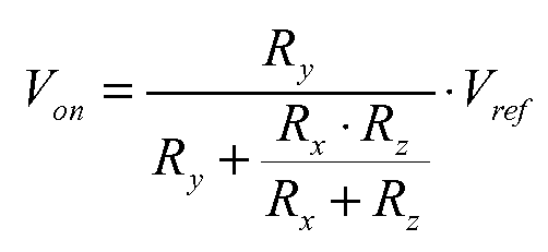
이어서, 비교기 출력은 접지 레벨로 전환되고, 스위치(27)는 턴오프된다. 이제 LED 전류는 비교기의 반전 입력에서의 전압이 제2 전이 전압(Voff)에 도달할 때까지 감소되며, 이 제2 전이 전압은 아래와 같이 정의된다.The comparator output is then switched to ground level and

이 때, 스위치는 다시 턴온되고, 새로운 사이클이 자기 발진(self oscillating)식으로 시작된다. Voff는 Von보다 낮고, 평균 LED 전류 및 허용된 맥류 (ripple current) 둘 다는 Vref, Rx, Ry, Rz에 의해 설정된다. 히스테리시스 또는 뱅뱅(bang-bang) 구성에 의해, LED 전류 내의 전이 전류 뿐만 아니라 LED 맥류도 낮게 유지될 수 있고, 이것은 LED가 뚜렷한 색과 강도로 발광할 수 있게 한다. At this time, the switch is turned on again, and a new cycle starts with self oscillating. V off is lower than V on , and both the average LED current and the allowed ripple current are set by V ref , R x , R y , R z . By hysteresis or bang-bang configuration, not only the transition current in the LED current but also the LED pulsation can be kept low, which allows the LED to emit light with distinct color and intensity.
로우-패스 필터(23)는, 저항기(Rf)와 커패시터(Cf)를 구비하는 간단한 제1차 버터워스(Butterworth) 필터를 포함할 수 있다. 로우-패스 필터에 의해, 스위치가 턴온 또는 턴오프될 때 발생하는 스위치(17)의 잠재적인 고주파 잡음이 필터링될 수 있다. 이에 따라 잡음이 거의 없는 삼각파 전압이 발생하며, 이는 비교기의 반전 입력에 입력되는 LED 전류(ILED)를 나타낸다.The low-
도시한 회로는 매우 적은 비용으로 얻을 수 있다. 4개의 비교기를 포함하는 표준 집적 회로는, 저 비용으로 이용가능하며, 이에 따라 예를 들어 하나의 칩과 몇 개의 간단한 추가 컴포넌트만을 갖는 RGBA 유닛이 얻어질 수 있게 한다.The illustrated circuit can be obtained at a very low cost. A standard integrated circuit comprising four comparators is available at low cost, thus allowing for example an RGBA unit with only one chip and a few simple additional components to be obtained.
광 흐름은 비교기(31)의 출력에서 스위치(17, 예를 들어, MOSFET)를 이용하여 펄스폭 변조(PWM) 제어될 수 있다. 이 스위치(17)의 게이트는 제어 입력 단자(5)에 연결되고, 스위치(17)가 턴온되면, 비교기는 접지되고 드라이버 회로(1)는 스위칭 오프된다. 이것은, 스위치(17)의 듀티 사이클을 가변함으로써, LED로부터의 광 흐름을 PWM 제어할 수 있게 한다. 물론, 이것은, 다운 컨버터(11)의 수백 kHz일 수 있는 스위칭 주파수와 비교할 때 예를 들어 수백 Hz인 낮은 스위칭 주파수로 행해진다.Light flow may be pulse width modulated (PWM) controlled using a switch 17 (eg, a MOSFET) at the output of the
도 3은 다른 실시예에서의 LED 드라이버 회로의 상세를 도시한다. 이 실시예에서는, 도 2의 스위치(17)가 필요없다. 대신에, LED 전류는 추가 저항기(Ry1)를 저항기(Ry)에 병렬로 연결하는 스위치(19)에 의해 변경될 수 있다. 전술한 등식들로부터 알 수 있듯이, 이것은 전이 레벨(Von 및 Voff)을 변경한다. 이러한 제어 장치는, 평균 LED 전류가 2개 값 중 임의의 값으로 변경될 수 있게 하며, 이에 따라 PWM 해결책보다는 덜 유연하지만 덜 복잡하게 된다. 일반적으로, 이 실시예에서 는, 하나 이상의 스위치가 사용되며, 이 스위치는 비교기 회로 내의 분압기 네트워크에 영향을 끼친다. 하나보다 많은 스위치가 사용되면, 2개보다 많은 넌제로(non-zero) LED 전류값들이 가능해진다. 따라서, 이 스위치 또는 하나보다 많은 스위치는 하나의 저항기를 저항기들(Rx, Ry, Rz) 중 하나 이상에 병렬로 연결하는 데 적용될 수 있다. 원칙적으로, 이 실시예는 도 1의 PWM 해결책과 조합될 수 있다.3 shows details of an LED driver circuit in another embodiment. In this embodiment, the
요약하자면, 본 발명은, 다운 컨버팅 특징부를 갖고 비교기에 의해 제어되는 스위칭 모드 전원(smps)을 포함하는 저 비용 LED 드라이버 모듈에 관한 것이다. 이 비교기는 히스테리시스로 구성되며, 이것은 LED 전류 내의 맥류와 전이 전류를 줄이며, 이 LED 드라이버 모듈은 저가의 표준 컴포넌트들로 이루어질 수 있다.In summary, the present invention relates to a low cost LED driver module that includes a switching mode power supply (smps) having down converting features and controlled by a comparator. The comparator consists of hysteresis, which reduces the ripple and transition currents in the LED current, which can be made up of low-cost standard components.
본 발명은, 기준 전압 신호가 재사용될 수 있으며 추가 제어가능 LED 드라이버 회로를 얻고 이에 따라 예를 들어 추가 LED 채널인 수 개의 저항기와 비교기, 비교기, 다이오드, 인덕터를 얻는 데 있어서 적은 개수의 추가 컴포넌트만이 필요하다는 사실로 인해, LED들의 다수의 스트링을 갖는 응용에 특히 유용하다.The present invention allows only a small number of additional components in obtaining a further controllable LED driver circuit whereby the reference voltage signal can be reused and thus obtaining several resistors and comparators, comparators, diodes, inductors, for example, additional LED channels. Due to the fact that this is necessary, it is particularly useful for applications with multiple strings of LEDs.
본 발명은 전술한 실시예들로 한정되지 않는다. 본 발명은 청구범위 내에서 다양한 방식으로 변경될 수 있다.The invention is not limited to the embodiments described above. The invention can be modified in various ways within the scope of the claims.
Claims (6)
Applications Claiming Priority (3)
| Application Number | Priority Date | Filing Date | Title |
|---|---|---|---|
| EP06101079 | 2006-01-31 | ||
| EP06101079.9 | 2006-01-31 | ||
| PCT/IB2007/050279 WO2007088505A1 (en) | 2006-01-31 | 2007-01-26 | Led driver circuit |
Publications (2)
| Publication Number | Publication Date |
|---|---|
| KR20080098396A true KR20080098396A (en) | 2008-11-07 |
| KR101303362B1 KR101303362B1 (en) | 2013-09-03 |
Family
ID=37905021
Family Applications (1)
| Application Number | Title | Priority Date | Filing Date |
|---|---|---|---|
| KR1020087021117A Active KR101303362B1 (en) | 2006-01-31 | 2007-01-26 | Led driver circuit |
Country Status (7)
| Country | Link |
|---|---|
| US (1) | US8217587B2 (en) |
| EP (1) | EP1982560A1 (en) |
| JP (1) | JP5329235B2 (en) |
| KR (1) | KR101303362B1 (en) |
| CN (1) | CN101379879B (en) |
| TW (1) | TWI434609B (en) |
| WO (1) | WO2007088505A1 (en) |
Families Citing this family (58)
| Publication number | Priority date | Publication date | Assignee | Title |
|---|---|---|---|---|
| US20050259424A1 (en) * | 2004-05-18 | 2005-11-24 | Zampini Thomas L Ii | Collimating and controlling light produced by light emitting diodes |
| US7766511B2 (en) * | 2006-04-24 | 2010-08-03 | Integrated Illumination Systems | LED light fixture |
| US7746300B2 (en) | 2006-05-05 | 2010-06-29 | Linear Technology Corporation | Circuit and methodology for supplying pulsed current to a load, such as a light emitting diode |
| US8324816B2 (en) * | 2006-10-18 | 2012-12-04 | Koa Corporation | LED driving circuit |
| US7729941B2 (en) | 2006-11-17 | 2010-06-01 | Integrated Illumination Systems, Inc. | Apparatus and method of using lighting systems to enhance brand recognition |
| WO2008068705A1 (en) * | 2006-12-06 | 2008-06-12 | Nxp B.V. | Controlled voltage source for led drivers |
| US8013538B2 (en) | 2007-01-26 | 2011-09-06 | Integrated Illumination Systems, Inc. | TRI-light |
| CN101772798B (en) * | 2007-08-02 | 2012-10-31 | 皇家飞利浦电子股份有限公司 | light output device |
| US8742686B2 (en) * | 2007-09-24 | 2014-06-03 | Integrated Illumination Systems, Inc. | Systems and methods for providing an OEM level networked lighting system |
| DE102007047725A1 (en) * | 2007-10-05 | 2009-04-09 | Texas Instruments Deutschland Gmbh | Electronic device, has control stage for controlling switched voltage converter in response to error signal such that converter supplies preset average current, and light-emitting semiconductor device coupled with output node |
| EP2066149A3 (en) * | 2007-11-27 | 2009-08-19 | Stefan Ruppel | Flat LED lights with heat-dispersing board, in particular for furniture |
| US8255487B2 (en) * | 2008-05-16 | 2012-08-28 | Integrated Illumination Systems, Inc. | Systems and methods for communicating in a lighting network |
| JP2010080524A (en) * | 2008-09-24 | 2010-04-08 | Sanyo Electric Co Ltd | Light-emitting element drive control circuit |
| DE102009007503A1 (en) * | 2009-02-05 | 2010-08-12 | E:Cue Control Gmbh | lighting arrangement |
| US20120039045A1 (en) * | 2009-04-22 | 2012-02-16 | Mitsubishi Electric Corporation | Power module and method for detecting insulation degradation thereof |
| US8585245B2 (en) | 2009-04-23 | 2013-11-19 | Integrated Illumination Systems, Inc. | Systems and methods for sealing a lighting fixture |
| WO2011001369A2 (en) | 2009-07-03 | 2011-01-06 | Koninklijke Philips Electronics N.V. | Low cost power supply circuit and method |
| US8525434B2 (en) * | 2009-10-07 | 2013-09-03 | Marvell World Trade Ltd. | Method and apparatus for power driving |
| TWI411354B (en) * | 2009-11-03 | 2013-10-01 | Himax Analogic Inc | Switching circuit and led circuit |
| ITPR20100006A1 (en) * | 2010-01-29 | 2011-07-30 | Light & Colour Engineering S R L | LIGHTING DEVICE. |
| WO2011126374A2 (en) * | 2010-04-09 | 2011-10-13 | Eldolab Holding B.V. | Driver system for driving a plurality of led's |
| IT1399217B1 (en) * | 2010-04-09 | 2013-04-11 | Artemide Spa | LED LIGHTING APPLIANCE WITH LIGHTING INTENSITY ADJUSTMENT |
| US8450936B1 (en) | 2010-05-13 | 2013-05-28 | Whelen Engineering Company, Inc. | Dual range power supply |
| TWI422279B (en) * | 2010-05-28 | 2014-01-01 | Himax Analogic Inc | Light emitting diode driving circuit |
| US8525437B2 (en) | 2010-09-16 | 2013-09-03 | Samsung Electro-Mechanics Co., Ltd. | Device for controlling current of LED |
| US9491822B2 (en) * | 2010-10-01 | 2016-11-08 | Intersil Americas LLC | LED driver with adaptive dynamic headroom voltage control |
| IT1403159B1 (en) * | 2010-12-02 | 2013-10-04 | Osram Spa | CONVERTER DEVICE. |
| US9066381B2 (en) | 2011-03-16 | 2015-06-23 | Integrated Illumination Systems, Inc. | System and method for low level dimming |
| US9967940B2 (en) | 2011-05-05 | 2018-05-08 | Integrated Illumination Systems, Inc. | Systems and methods for active thermal management |
| US8188671B2 (en) * | 2011-06-07 | 2012-05-29 | Switch Bulb Company, Inc. | Power factor control for an LED bulb driver circuit |
| US20150237700A1 (en) | 2011-07-26 | 2015-08-20 | Hunter Industries, Inc. | Systems and methods to control color and brightness of lighting devices |
| US11917740B2 (en) | 2011-07-26 | 2024-02-27 | Hunter Industries, Inc. | Systems and methods for providing power and data to devices |
| US8710770B2 (en) | 2011-07-26 | 2014-04-29 | Hunter Industries, Inc. | Systems and methods for providing power and data to lighting devices |
| US9609720B2 (en) | 2011-07-26 | 2017-03-28 | Hunter Industries, Inc. | Systems and methods for providing power and data to lighting devices |
| US10874003B2 (en) | 2011-07-26 | 2020-12-22 | Hunter Industries, Inc. | Systems and methods for providing power and data to devices |
| US9521725B2 (en) | 2011-07-26 | 2016-12-13 | Hunter Industries, Inc. | Systems and methods for providing power and data to lighting devices |
| US8604699B2 (en) * | 2011-12-07 | 2013-12-10 | Atmel Corporation | Self-power for device driver |
| EP2798916B1 (en) * | 2011-12-28 | 2017-05-03 | OSRAM GmbH | Converter device |
| US8894437B2 (en) | 2012-07-19 | 2014-11-25 | Integrated Illumination Systems, Inc. | Systems and methods for connector enabling vertical removal |
| US9379578B2 (en) | 2012-11-19 | 2016-06-28 | Integrated Illumination Systems, Inc. | Systems and methods for multi-state power management |
| DE102012111317B4 (en) | 2012-11-23 | 2021-07-22 | HELLA GmbH & Co. KGaA | Circuit arrangement with a step-down converter |
| US9420665B2 (en) | 2012-12-28 | 2016-08-16 | Integration Illumination Systems, Inc. | Systems and methods for continuous adjustment of reference signal to control chip |
| US9485814B2 (en) * | 2013-01-04 | 2016-11-01 | Integrated Illumination Systems, Inc. | Systems and methods for a hysteresis based driver using a LED as a voltage reference |
| CN103209531B (en) * | 2013-04-28 | 2014-11-26 | 宁波赛耐比光电有限公司 | LED (Light Emitting Diode) dimming control circuit |
| CN104470060B (en) * | 2014-10-20 | 2017-09-15 | 深圳市华星光电技术有限公司 | Simulation light modulation change-over circuit and display device |
| DE102015208078A1 (en) * | 2015-04-30 | 2016-11-03 | Osram Gmbh | Circuit arrangement and method for reducing the light modulation of at least one voltage source operated at a voltage |
| US10918030B2 (en) | 2015-05-26 | 2021-02-16 | Hunter Industries, Inc. | Decoder systems and methods for irrigation control |
| US10228711B2 (en) | 2015-05-26 | 2019-03-12 | Hunter Industries, Inc. | Decoder systems and methods for irrigation control |
| US10030844B2 (en) | 2015-05-29 | 2018-07-24 | Integrated Illumination Systems, Inc. | Systems, methods and apparatus for illumination using asymmetrical optics |
| US10060599B2 (en) | 2015-05-29 | 2018-08-28 | Integrated Illumination Systems, Inc. | Systems, methods and apparatus for programmable light fixtures |
| US10117298B1 (en) | 2017-04-11 | 2018-10-30 | Seasons 4, Inc. | Curtain-configured light strings |
| US9986610B1 (en) | 2017-04-11 | 2018-05-29 | Seasons 4, Inc. | Long-chain-tolerant decorative strings of independently illumination controllable LEDs |
| US10337710B2 (en) | 2017-04-11 | 2019-07-02 | Seasons 4, Inc. | Tree with integrated lighting elements receiving power and control data over common conductors |
| US10225916B2 (en) | 2017-04-11 | 2019-03-05 | Seasons 4, Inc. | Data/power controller for translation between light control protocols |
| US10483850B1 (en) | 2017-09-18 | 2019-11-19 | Ecosense Lighting Inc. | Universal input-voltage-compatible switched-mode power supply |
| US10801714B1 (en) | 2019-10-03 | 2020-10-13 | CarJamz, Inc. | Lighting device |
| US12416908B2 (en) | 2022-12-29 | 2025-09-16 | Integrated Illumination Systems, Inc. | Systems and methods for manufacturing light fixtures |
| US12297996B2 (en) | 2023-02-16 | 2025-05-13 | Integrated Illumination Systems, Inc. | Cove light fixture with hidden integrated air return |
Family Cites Families (21)
| Publication number | Priority date | Publication date | Assignee | Title |
|---|---|---|---|---|
| US4504776A (en) * | 1980-11-12 | 1985-03-12 | Bei Electronics, Inc. | Power saving regulated light emitting diode circuit |
| JPH0594151A (en) * | 1991-08-08 | 1993-04-16 | Seiwa Denki Kk | LED lighting circuit |
| JP3457763B2 (en) * | 1995-04-13 | 2003-10-20 | アルプス電気株式会社 | Light emitting element drive circuit |
| FI106770B (en) * | 1999-01-22 | 2001-03-30 | Nokia Mobile Phones Ltd | Illuminating electronic device and lighting method |
| US6618031B1 (en) * | 1999-02-26 | 2003-09-09 | Three-Five Systems, Inc. | Method and apparatus for independent control of brightness and color balance in display and illumination systems |
| US6404265B1 (en) * | 1999-08-13 | 2002-06-11 | York International Corporation | Highly efficient driver circuit for a solid state switch |
| JP3445540B2 (en) * | 1999-11-16 | 2003-09-08 | 常盤電業株式会社 | Power circuit |
| US6396217B1 (en) * | 2000-12-22 | 2002-05-28 | Visteon Global Technologies, Inc. | Brightness offset error reduction system and method for a display device |
| US7071762B2 (en) * | 2001-01-31 | 2006-07-04 | Koninklijke Philips Electronics N.V. | Supply assembly for a led lighting module |
| DE10225670A1 (en) | 2002-06-10 | 2003-12-24 | Patent Treuhand Ges Fuer Elektrische Gluehlampen Mbh | Control circuit for at least one LED string |
| JP4148746B2 (en) * | 2002-10-08 | 2008-09-10 | 株式会社小糸製作所 | Lighting circuit |
| WO2004100614A1 (en) * | 2003-05-07 | 2004-11-18 | Koninklijke Philips Electronics N.V. | Current control method and circuit for light emitting diodes |
| JP2005005112A (en) * | 2003-06-11 | 2005-01-06 | Yazaki Corp | LED drive circuit |
| CN2631184Y (en) * | 2003-07-17 | 2004-08-04 | 上海精密科学仪器有限公司 | LED drive circuit |
| JP4052998B2 (en) * | 2003-11-25 | 2008-02-27 | シャープ株式会社 | Power supply circuit and electronic device using the same |
| DK3589081T3 (en) * | 2004-03-15 | 2024-03-18 | Signify North America Corp | POWER CONTROL METHODS AND APPARATUS |
| TWI236165B (en) * | 2004-07-30 | 2005-07-11 | Au Optronics Corp | Driving device for light emitted diode string |
| US7675487B2 (en) | 2005-07-15 | 2010-03-09 | Honeywell International, Inc. | Simplified light-emitting diode (LED) hysteretic current controller |
| US7259525B2 (en) * | 2005-11-03 | 2007-08-21 | System General Corporation | High efficiency switching LED driver |
| US7602305B2 (en) * | 2005-11-15 | 2009-10-13 | Skyline Products, Inc. | Feedback circuit for a display sign and method |
| US20070114951A1 (en) * | 2005-11-22 | 2007-05-24 | Tsen Chia-Hung | Drive circuit for a light emitting diode array |
-
2007
- 2007-01-26 KR KR1020087021117A patent/KR101303362B1/en active Active
- 2007-01-26 WO PCT/IB2007/050279 patent/WO2007088505A1/en not_active Ceased
- 2007-01-26 US US12/162,372 patent/US8217587B2/en active Active
- 2007-01-26 CN CN2007800041739A patent/CN101379879B/en active Active
- 2007-01-26 EP EP07705719A patent/EP1982560A1/en not_active Ceased
- 2007-01-26 JP JP2008551939A patent/JP5329235B2/en active Active
- 2007-01-29 TW TW096103240A patent/TWI434609B/en active
Also Published As
| Publication number | Publication date |
|---|---|
| JP5329235B2 (en) | 2013-10-30 |
| US8217587B2 (en) | 2012-07-10 |
| KR101303362B1 (en) | 2013-09-03 |
| EP1982560A1 (en) | 2008-10-22 |
| JP2009525595A (en) | 2009-07-09 |
| TWI434609B (en) | 2014-04-11 |
| US20090021182A1 (en) | 2009-01-22 |
| TW200803618A (en) | 2008-01-01 |
| WO2007088505A1 (en) | 2007-08-09 |
| CN101379879B (en) | 2011-08-17 |
| CN101379879A (en) | 2009-03-04 |
Similar Documents
| Publication | Publication Date | Title |
|---|---|---|
| KR101303362B1 (en) | Led driver circuit | |
| US9699844B2 (en) | Multichannel constant current LED driving circuit, driving method and LED driving power | |
| KR101835255B1 (en) | Boost then floating buck mode converter for led driver using common switch control signal | |
| US8093822B2 (en) | LED driver and control method thereof | |
| KR100867551B1 (en) | LED array driving device | |
| US7595622B1 (en) | System and method for providing a sample and hold circuit for maintaining an output voltage of a constant current source circuit when a feedback loop is disconnected | |
| US9648677B2 (en) | LED driving circuit and method using single inductor | |
| US20170347417A1 (en) | Control circuit, control method and switching power supply thereof | |
| KR102050173B1 (en) | Switching converters and control circuits thereof, lighting devices using them, electronic equipment | |
| KR20120038466A (en) | Low cost power supply circuit and method | |
| US20190159308A1 (en) | Line ripple reducer | |
| US11743990B2 (en) | Balance control for 2-channel CCT dimming | |
| JP2019061854A (en) | Lighting system, luminaire apparatus, lighting control system, and program | |
| US9825528B2 (en) | Compensating for voltage changes in driver circuits | |
| US10461633B2 (en) | DC-to-DC drivers with high resolution dimming | |
| KR20130027854A (en) | Backlight unit | |
| US20120119671A1 (en) | Apparatus and method for circuit configuration for powering light emitting diodes | |
| EP2897272B1 (en) | Method and converter for supplying current to series connection of LEDs | |
| HK40063609A (en) | Method and devices for regulating the output voltage of a voltage regulator | |
| HK40063609B (en) | Method and devices for regulating the output voltage of a voltage regulator |
Legal Events
| Date | Code | Title | Description |
|---|---|---|---|
| PA0105 | International application |
St.27 status event code: A-0-1-A10-A15-nap-PA0105 |
|
| E13-X000 | Pre-grant limitation requested |
St.27 status event code: A-2-3-E10-E13-lim-X000 |
|
| P11-X000 | Amendment of application requested |
St.27 status event code: A-2-2-P10-P11-nap-X000 |
|
| P13-X000 | Application amended |
St.27 status event code: A-2-2-P10-P13-nap-X000 |
|
| PG1501 | Laying open of application |
St.27 status event code: A-1-1-Q10-Q12-nap-PG1501 |
|
| A201 | Request for examination | ||
| PA0201 | Request for examination |
St.27 status event code: A-1-2-D10-D11-exm-PA0201 |
|
| E902 | Notification of reason for refusal | ||
| PE0902 | Notice of grounds for rejection |
St.27 status event code: A-1-2-D10-D21-exm-PE0902 |
|
| P11-X000 | Amendment of application requested |
St.27 status event code: A-2-2-P10-P11-nap-X000 |
|
| P13-X000 | Application amended |
St.27 status event code: A-2-2-P10-P13-nap-X000 |
|
| R18-X000 | Changes to party contact information recorded |
St.27 status event code: A-3-3-R10-R18-oth-X000 |
|
| E701 | Decision to grant or registration of patent right | ||
| PE0701 | Decision of registration |
St.27 status event code: A-1-2-D10-D22-exm-PE0701 |
|
| GRNT | Written decision to grant | ||
| PR0701 | Registration of establishment |
St.27 status event code: A-2-4-F10-F11-exm-PR0701 |
|
| PR1002 | Payment of registration fee |
St.27 status event code: A-2-2-U10-U12-oth-PR1002 Fee payment year number: 1 |
|
| PG1601 | Publication of registration |
St.27 status event code: A-4-4-Q10-Q13-nap-PG1601 |
|
| PN2301 | Change of applicant |
St.27 status event code: A-5-5-R10-R13-asn-PN2301 St.27 status event code: A-5-5-R10-R11-asn-PN2301 |
|
| FPAY | Annual fee payment |
Payment date: 20160819 Year of fee payment: 4 |
|
| PR1001 | Payment of annual fee |
St.27 status event code: A-4-4-U10-U11-oth-PR1001 Fee payment year number: 4 |
|
| P22-X000 | Classification modified |
St.27 status event code: A-4-4-P10-P22-nap-X000 |
|
| PN2301 | Change of applicant |
St.27 status event code: A-5-5-R10-R11-asn-PN2301 |
|
| PN2301 | Change of applicant |
St.27 status event code: A-5-5-R10-R11-asn-PN2301 |
|
| PN2301 | Change of applicant |
St.27 status event code: A-5-5-R10-R14-asn-PN2301 |
|
| FPAY | Annual fee payment |
Payment date: 20170822 Year of fee payment: 5 |
|
| PR1001 | Payment of annual fee |
St.27 status event code: A-4-4-U10-U11-oth-PR1001 Fee payment year number: 5 |
|
| FPAY | Annual fee payment |
Payment date: 20180822 Year of fee payment: 6 |
|
| PR1001 | Payment of annual fee |
St.27 status event code: A-4-4-U10-U11-oth-PR1001 Fee payment year number: 6 |
|
| P22-X000 | Classification modified |
St.27 status event code: A-4-4-P10-P22-nap-X000 |
|
| R18-X000 | Changes to party contact information recorded |
St.27 status event code: A-5-5-R10-R18-oth-X000 |
|
| FPAY | Annual fee payment |
Payment date: 20190821 Year of fee payment: 7 |
|
| PR1001 | Payment of annual fee |
St.27 status event code: A-4-4-U10-U11-oth-PR1001 Fee payment year number: 7 |
|
| P22-X000 | Classification modified |
St.27 status event code: A-4-4-P10-P22-nap-X000 |
|
| P22-X000 | Classification modified |
St.27 status event code: A-4-4-P10-P22-nap-X000 |
|
| PR1001 | Payment of annual fee |
St.27 status event code: A-4-4-U10-U11-oth-PR1001 Fee payment year number: 8 |
|
| PR1001 | Payment of annual fee |
St.27 status event code: A-4-4-U10-U11-oth-PR1001 Fee payment year number: 9 |
|
| R18-X000 | Changes to party contact information recorded |
St.27 status event code: A-5-5-R10-R18-oth-X000 |
|
| PR1001 | Payment of annual fee |
St.27 status event code: A-4-4-U10-U11-oth-PR1001 Fee payment year number: 10 |
|
| PR1001 | Payment of annual fee |
St.27 status event code: A-4-4-U10-U11-oth-PR1001 Fee payment year number: 11 |
|
| PR1001 | Payment of annual fee |
St.27 status event code: A-4-4-U10-U11-oth-PR1001 Fee payment year number: 12 |
|
| PR1001 | Payment of annual fee |
St.27 status event code: A-4-4-U10-U11-oth-PR1001 Fee payment year number: 13 |
|
| U11 | Full renewal or maintenance fee paid |
Free format text: ST27 STATUS EVENT CODE: A-4-4-U10-U11-OTH-PR1001 (AS PROVIDED BY THE NATIONAL OFFICE) Year of fee payment: 13 |