KR20080098323A - Charging device with battery capacity analysis - Google Patents
Charging device with battery capacity analysis Download PDFInfo
- Publication number
- KR20080098323A KR20080098323A KR1020080041233A KR20080041233A KR20080098323A KR 20080098323 A KR20080098323 A KR 20080098323A KR 1020080041233 A KR1020080041233 A KR 1020080041233A KR 20080041233 A KR20080041233 A KR 20080041233A KR 20080098323 A KR20080098323 A KR 20080098323A
- Authority
- KR
- South Korea
- Prior art keywords
- battery
- unit
- charging
- charging device
- discharge
- Prior art date
- Legal status (The legal status is an assumption and is not a legal conclusion. Google has not performed a legal analysis and makes no representation as to the accuracy of the status listed.)
- Ceased
Links
Images


Classifications
-
- G—PHYSICS
- G01—MEASURING; TESTING
- G01R—MEASURING ELECTRIC VARIABLES; MEASURING MAGNETIC VARIABLES
- G01R31/00—Arrangements for testing electric properties; Arrangements for locating electric faults; Arrangements for electrical testing characterised by what is being tested not provided for elsewhere
- G01R31/36—Arrangements for testing, measuring or monitoring the electrical condition of accumulators or electric batteries, e.g. capacity or state of charge [SoC]
- G01R31/382—Arrangements for monitoring battery or accumulator variables, e.g. SoC
-
- H—ELECTRICITY
- H01—ELECTRIC ELEMENTS
- H01M—PROCESSES OR MEANS, e.g. BATTERIES, FOR THE DIRECT CONVERSION OF CHEMICAL ENERGY INTO ELECTRICAL ENERGY
- H01M10/00—Secondary cells; Manufacture thereof
- H01M10/42—Methods or arrangements for servicing or maintenance of secondary cells or secondary half-cells
- H01M10/4285—Testing apparatus
-
- H—ELECTRICITY
- H02—GENERATION; CONVERSION OR DISTRIBUTION OF ELECTRIC POWER
- H02J—ELECTRIC POWER NETWORKS; CIRCUIT ARRANGEMENTS OR SYSTEMS FOR SUPPLYING OR DISTRIBUTING ELECTRIC POWER; SYSTEMS FOR STORING ELECTRIC ENERGY
- H02J7/00—Circuit arrangements for charging or discharging batteries or for supplying loads from batteries
- H02J7/80—Circuit arrangements for charging or discharging batteries or for supplying loads from batteries including monitoring or indicating arrangements
-
- G—PHYSICS
- G01—MEASURING; TESTING
- G01R—MEASURING ELECTRIC VARIABLES; MEASURING MAGNETIC VARIABLES
- G01R31/00—Arrangements for testing electric properties; Arrangements for locating electric faults; Arrangements for electrical testing characterised by what is being tested not provided for elsewhere
- G01R31/36—Arrangements for testing, measuring or monitoring the electrical condition of accumulators or electric batteries, e.g. capacity or state of charge [SoC]
- G01R31/371—Arrangements for testing, measuring or monitoring the electrical condition of accumulators or electric batteries, e.g. capacity or state of charge [SoC] with remote indication, e.g. on external chargers
-
- H—ELECTRICITY
- H01—ELECTRIC ELEMENTS
- H01M—PROCESSES OR MEANS, e.g. BATTERIES, FOR THE DIRECT CONVERSION OF CHEMICAL ENERGY INTO ELECTRICAL ENERGY
- H01M10/00—Secondary cells; Manufacture thereof
- H01M10/42—Methods or arrangements for servicing or maintenance of secondary cells or secondary half-cells
- H01M10/44—Methods for charging or discharging
-
- H—ELECTRICITY
- H01—ELECTRIC ELEMENTS
- H01M—PROCESSES OR MEANS, e.g. BATTERIES, FOR THE DIRECT CONVERSION OF CHEMICAL ENERGY INTO ELECTRICAL ENERGY
- H01M10/00—Secondary cells; Manufacture thereof
- H01M10/42—Methods or arrangements for servicing or maintenance of secondary cells or secondary half-cells
- H01M10/48—Accumulators combined with arrangements for measuring, testing or indicating the condition of cells, e.g. the level or density of the electrolyte
- H01M10/488—Cells or batteries combined with indicating means for external visualization of the condition, e.g. by change of colour or of light density
-
- H—ELECTRICITY
- H02—GENERATION; CONVERSION OR DISTRIBUTION OF ELECTRIC POWER
- H02J—ELECTRIC POWER NETWORKS; CIRCUIT ARRANGEMENTS OR SYSTEMS FOR SUPPLYING OR DISTRIBUTING ELECTRIC POWER; SYSTEMS FOR STORING ELECTRIC ENERGY
- H02J7/00—Circuit arrangements for charging or discharging batteries or for supplying loads from batteries
- H02J7/60—Circuit arrangements for charging or discharging batteries or for supplying loads from batteries including safety or protection arrangements
- H02J7/663—Circuit arrangements for charging or discharging batteries or for supplying loads from batteries including safety or protection arrangements using battery or load disconnect circuits
-
- H—ELECTRICITY
- H02—GENERATION; CONVERSION OR DISTRIBUTION OF ELECTRIC POWER
- H02J—ELECTRIC POWER NETWORKS; CIRCUIT ARRANGEMENTS OR SYSTEMS FOR SUPPLYING OR DISTRIBUTING ELECTRIC POWER; SYSTEMS FOR STORING ELECTRIC ENERGY
- H02J7/00—Circuit arrangements for charging or discharging batteries or for supplying loads from batteries
- H02J7/80—Circuit arrangements for charging or discharging batteries or for supplying loads from batteries including monitoring or indicating arrangements
- H02J7/82—Control of state of charge [SOC]
- H02J7/825—Detection of fully charged condition
-
- G—PHYSICS
- G01—MEASURING; TESTING
- G01R—MEASURING ELECTRIC VARIABLES; MEASURING MAGNETIC VARIABLES
- G01R31/00—Arrangements for testing electric properties; Arrangements for locating electric faults; Arrangements for electrical testing characterised by what is being tested not provided for elsewhere
- G01R31/36—Arrangements for testing, measuring or monitoring the electrical condition of accumulators or electric batteries, e.g. capacity or state of charge [SoC]
- G01R31/3644—Constructional arrangements
- G01R31/3648—Constructional arrangements comprising digital calculation means, e.g. for performing an algorithm
-
- G—PHYSICS
- G01—MEASURING; TESTING
- G01R—MEASURING ELECTRIC VARIABLES; MEASURING MAGNETIC VARIABLES
- G01R31/00—Arrangements for testing electric properties; Arrangements for locating electric faults; Arrangements for electrical testing characterised by what is being tested not provided for elsewhere
- G01R31/36—Arrangements for testing, measuring or monitoring the electrical condition of accumulators or electric batteries, e.g. capacity or state of charge [SoC]
- G01R31/367—Software therefor, e.g. for battery testing using modelling or look-up tables
-
- G—PHYSICS
- G01—MEASURING; TESTING
- G01R—MEASURING ELECTRIC VARIABLES; MEASURING MAGNETIC VARIABLES
- G01R31/00—Arrangements for testing electric properties; Arrangements for locating electric faults; Arrangements for electrical testing characterised by what is being tested not provided for elsewhere
- G01R31/36—Arrangements for testing, measuring or monitoring the electrical condition of accumulators or electric batteries, e.g. capacity or state of charge [SoC]
- G01R31/389—Measuring internal impedance, internal conductance or related variables
-
- H—ELECTRICITY
- H02—GENERATION; CONVERSION OR DISTRIBUTION OF ELECTRIC POWER
- H02J—ELECTRIC POWER NETWORKS; CIRCUIT ARRANGEMENTS OR SYSTEMS FOR SUPPLYING OR DISTRIBUTING ELECTRIC POWER; SYSTEMS FOR STORING ELECTRIC ENERGY
- H02J7/00—Circuit arrangements for charging or discharging batteries or for supplying loads from batteries
- H02J7/60—Circuit arrangements for charging or discharging batteries or for supplying loads from batteries including safety or protection arrangements
- H02J7/63—Circuit arrangements for charging or discharging batteries or for supplying loads from batteries including safety or protection arrangements against overdischarge
-
- H—ELECTRICITY
- H02—GENERATION; CONVERSION OR DISTRIBUTION OF ELECTRIC POWER
- H02J—ELECTRIC POWER NETWORKS; CIRCUIT ARRANGEMENTS OR SYSTEMS FOR SUPPLYING OR DISTRIBUTING ELECTRIC POWER; SYSTEMS FOR STORING ELECTRIC ENERGY
- H02J7/00—Circuit arrangements for charging or discharging batteries or for supplying loads from batteries
- H02J7/80—Circuit arrangements for charging or discharging batteries or for supplying loads from batteries including monitoring or indicating arrangements
- H02J7/82—Control of state of charge [SOC]
-
- Y—GENERAL TAGGING OF NEW TECHNOLOGICAL DEVELOPMENTS; GENERAL TAGGING OF CROSS-SECTIONAL TECHNOLOGIES SPANNING OVER SEVERAL SECTIONS OF THE IPC; TECHNICAL SUBJECTS COVERED BY FORMER USPC CROSS-REFERENCE ART COLLECTIONS [XRACs] AND DIGESTS
- Y02—TECHNOLOGIES OR APPLICATIONS FOR MITIGATION OR ADAPTATION AGAINST CLIMATE CHANGE
- Y02E—REDUCTION OF GREENHOUSE GAS [GHG] EMISSIONS, RELATED TO ENERGY GENERATION, TRANSMISSION OR DISTRIBUTION
- Y02E60/00—Enabling technologies; Technologies with a potential or indirect contribution to GHG emissions mitigation
- Y02E60/10—Energy storage using batteries
Landscapes
- Engineering & Computer Science (AREA)
- Manufacturing & Machinery (AREA)
- Chemical & Material Sciences (AREA)
- Chemical Kinetics & Catalysis (AREA)
- Electrochemistry (AREA)
- General Chemical & Material Sciences (AREA)
- Power Engineering (AREA)
- Physics & Mathematics (AREA)
- General Physics & Mathematics (AREA)
- Charge And Discharge Circuits For Batteries Or The Like (AREA)
- Secondary Cells (AREA)
Abstract
본 발명은 일종의 배터리용량 분석기능을 구비한 충전장치에 관한 것으로서, 충전장치는 제어유닛, 계산유닛, 디스플레이유닛, 충전유닛 및 방전유닛을 포함하며, 충전유닛이 배터리에 연결되어 충전을 진행할 때, 제어유닛을 통하여 배터리에 전력이 충분한지 여부를 판단하고, 충전이 다 된 후에, 충전유닛이 배터리 충전을 중지하는 동시에, 방전유닛이 배터리에 대하여 정전류 방전을 진행하고, 아울러 제어유닛으로 제어하며, 또한 배터리의 전력이 소진된 후 방전을 중지하여, 계산유닛이 배터리의 실제 유효용량을 판단하고 계산할 수 있도록 하는 동시에, 다시 계산된 용량 데이터를 디스플레이유닛으로 디스플레이한 후 이어서 배터리를 충전함으로써, 충전장치의 배터리용량 분석 및 충전 효과를 달성한다.The present invention relates to a charging device having a kind of battery capacity analysis function. The charging device includes a control unit, a calculation unit, a display unit, a charging unit, and a discharge unit, and when the charging unit is connected to a battery to perform charging, It is determined whether the battery has sufficient power through the control unit, and after the charging is completed, the charging unit stops charging the battery, the discharge unit performs constant current discharge on the battery, and also controls the control unit, In addition, after the battery power is exhausted, the discharge is stopped to allow the calculation unit to determine and calculate the actual effective capacity of the battery, and to display the calculated capacity data on the display unit and then charge the battery. Battery capacity analysis and charging effect is achieved.
Description
본 발명은 일종의 배터리용량 분석기능을 구비한 충전장치에 관한 것으로서, 충전장치를 이용하여 배터리를 충전할 때, 충전장치에 내장된 제어유닛을 통하여, 충전장치에 연결된 배터리가 충전되었는지 여부를 판단하고, 충전이 다 된 후, 상기 충전유닛이 배터리 충전을 중지하는 동시에, 방전유닛이 배터리에 대하여 정전류 방전을 실시함과 아울러, 제어유닛으로 제어하고, 배터리의 전력이 소진된 후 방전을 중지한다. The present invention relates to a charging device having a kind of battery capacity analysis function. When the battery is charged using the charging device, the control unit built in the charging device determines whether the battery connected to the charging device is charged. After the charging is completed, the charging unit stops charging the battery and at the same time, the discharge unit performs constant current discharge on the battery and controls the control unit and stops discharging after the battery power is exhausted.
일반적으로 시중에서 사용되는 충전설비(A)는 도 1 및 도 2에 도시된 바와 같이, 그 기능은 배터리(A1)에 연결되어 충전하는 것이며, 충전기(A2)를 배터리(A1)에 연결하여 충전할 때, 충전기(A2) 자체의 회로를 통해서는 배터리(A1)가 손상, 고장, 노화되었는지 또는 충전이 불가능한지 알 수 없다. 따라서 만약 배터리(A1)의 기능을 판단하고자 할 경우, 반드시 별도로 충전기(A2) 및 방전기(A3)를 연결하는 동시에, 배터리(A1)가 방전될 때 소모되는 총일률을 다시 계산해야만 배터리(A1)의 기능이 정상적인지 알 수 있다. 그런데, 별도로 연결되는 충전기(A2) 및 방전기(A3)는 사용이 불편할 뿐만 아니라, 설치 공간 및 원가가 증가하는 단점이 있다.In general, commercially available charging facility (A) is shown in Figures 1 and 2, its function is to charge the battery A1 is connected to, charging by connecting the charger (A2) to the battery (A1) In this case, the circuit of the charger A2 itself does not know whether the battery A1 is damaged, broken, aged, or impossible to charge. Therefore, if the function of the battery A1 is to be determined, the charger A2 and the discharger A3 must be connected separately, and the total power consumed when the battery A1 is discharged must be recalculated. It is possible to know if the function of is normal. However, the charger A2 and the discharger A3, which are separately connected, are not only inconvenient to use, but also have the disadvantage of increasing installation space and cost.
따라서, 본 발명은 상기 종래 기술의 단점을 해결하는 것을 목적으로 하며, 일종의 배터리용량 분석기능을 구비한 충전장치를 제공하여, 충전장치를 연결하여 배터리를 충전할 때, 충전장치에 내장된 제어유닛을 통하여 연결된 충전장치의 배터리가 충전되었는지 여부를 판단하고, 충전이 다 된 후, 충전유닛이 배터리 충전을 중지하는 동시에, 방전유닛이 배터리에 대하여 정전류 방전을 진행하고, 아울러 제어유닛으로 제어하며, 또한 배터리의 전력이 소진된 후 방전을 중지하여, 계산유닛이 배터리의 실제 유효용량을 판단하고 계산할 수 있도록 하는 동시에, 다시 계산된 용량 데이터를 디스플레이유닛으로 디스플레이한 후, 이어서 배터리를 충전함으로써 충전장치의 배터리용량 분석 및 충전 효과를 달성하도록 하는 것이다.Accordingly, an object of the present invention is to solve the disadvantages of the prior art, and provides a charging device having a kind of battery capacity analysis function, when connecting the charging device to charge the battery, the control unit built in the charging device It is determined whether the battery of the connected charging device is charged through, and after the charging is completed, the charging unit stops charging the battery, the discharge unit proceeds the constant current discharge to the battery, and also controlled by the control unit, In addition, after the battery power is exhausted, the discharge is stopped to allow the calculation unit to determine and calculate the actual effective capacity of the battery, and to display the calculated capacity data on the display unit and then charge the battery. To achieve the battery capacity analysis and charging effect.
본 발명의 제 1 측면은, 일종의 배터리용량 분석기능을 구비한 충전장치에 있어서, 상기 충전장치는 제어유닛, 계산유닛, 디스플레이유닛, 충전유닛 및 방전유닛을 포함하며, 충전유닛이 배터리에 연결되어 충전을 진행할 때, 제어유닛을 통하여 배터리의 전력이 충분한지 판단하고, 충전이 다 된 후에는 충전을 중지하는 동시에 방전유닛을 통하여 배터리를 방전하며, 아울러 제어유닛으로 제어하고, 배터리의 전력이 소진된 후 방전을 중지하여, 계산유닛이 배터리의 실제 유효용량을 계산하도록 하는 동시에, 계산된 실제 유효용량 데이터를 디스플레이유닛으로 디스플레이한 후, 충전장치의 배터리용량 분석 및 충전을 완성하는 것을 특징으로 하는 배터리용량 분석기능을 구비한 충전장치이다.According to a first aspect of the present invention, in a charging device having a kind of battery capacity analysis function, the charging device includes a control unit, a calculation unit, a display unit, a charging unit and a discharge unit, and the charging unit is connected to the battery. When charging is performed, it is determined whether the battery has sufficient power through the control unit, and after the charge is completed, the battery is stopped through the discharge unit and the battery is discharged through the discharge unit, and controlled by the control unit, and the battery power is exhausted. After the discharge is stopped, the calculation unit calculates the actual effective capacity of the battery, and displays the calculated actual effective capacity data on the display unit, and then analyzes the battery capacity of the charging device and completes the charging. It is a charging device with battery capacity analysis function.
본 발명의 제 2 측면은, 제 1 측면에 있어서, 디스플레이유닛은 LCD(액정디스플레이) 디스플레이장치, LED(발광다이오드) 디스플레이장치 및 디지털형 발광다이오드 및 데이터를 디스플레이할 수 있는 상관 장치로 설치 가능한 것을 특징으로 하는 배터리용량 분석기능을 구비한 충전장치이다.According to a second aspect of the present invention, in the first aspect, the display unit can be installed as an LCD (liquid crystal display) display device, an LED (light emitting diode) display device, and a correlated device capable of displaying digital light emitting diodes and data. It is a charging device with a battery capacity analysis function.
본 발명의 제 3 측면은, 제 1 측면에 있어서, 충전장치는 더 나아가 배터리가 충전 및 방전된 후, 용량을 기억하는 기능을 지닌 메모리유닛을 포함하는 것을 특징으로 하는 배터리용량 분석기능을 구비한 충전장치이다.The third aspect of the present invention provides a battery capacity analysis function according to the first aspect, wherein the charging device further includes a memory unit having a function of storing capacity after the battery is charged and discharged. It is a charging device.
본 발명의 제 4 측면은, 제 1 측면에 있어서, 방전유닛 내부에 설치된 소모 부하는 저항, 트랜지스터, MOS, 전자장치, 전구, 모터 등 공률을 소모할 수 있는 부하로 설정하는 것을 특징으로 하는 배터리용량 분석기능을 구비한 충전장치이다.According to a fourth aspect of the present invention, in the first aspect, the consumption load installed inside the discharge unit is set to a load capable of consuming power such as a resistor, a transistor, a MOS, an electronic device, a light bulb, a motor, and the like. It is a charging device with a capacity analysis function.
본 발명의 제 5 측면은, 제 1 측면에 있어서, 제어유닛 및 계산유닛 등 부재는 더 나아가 관련 회로의 연결 및 운용을 효과적으로 높일 수 있도록 모듈 및 집적회로(IC)로 통합할 수 있는 것을 특징으로 하는 배터리용량 분석기능을 구비한 충전장치이다.According to a fifth aspect of the present invention, in the first aspect, members such as a control unit and a calculation unit may further be integrated into modules and integrated circuits (ICs) so as to effectively increase connection and operation of related circuits. It is a charging device with a battery capacity analysis function.
본 발명의 진보성과 실용성을 더욱 명확히 드러내기 위하여, 장점들을 다음과 같이 열거한다.In order to more clearly show the progress and practicality of the present invention, the advantages are listed as follows.
1. 충전장치에 내장된 배터리용량 분석유닛, 제어유닛 및 계산유닛을 이용하여 배터리의 용량을 판단하고 정확히 환산할 수 있다.1. The battery capacity analysis unit, control unit and calculation unit built in the charging device can be used to determine and accurately convert the capacity of the battery.
2. 내장된 배터리용량 분석유닛을 통하여, 배터리의 양호 유무 및 실제 유효용량을 판단하고 분석함으로써, 충전 및 방전 검측기능의 목적을 달성할 수 있다.2. Through the built-in battery capacity analysis unit, it is possible to achieve the purpose of the charge and discharge detection function by determining and analyzing the good and actual effective capacity of the battery.
3. 배터리용량 분석유닛을 구비한 충전장치는 사용이 비교적 편리하고, 설치공간 및 원가 증가의 부담이 없다.3. The charging device equipped with the battery capacity analysis unit is relatively convenient to use, and there is no burden of installation space and cost increase.
4. 산업경쟁력을 갖추고 있다.4. It has industrial competitiveness.
5. 상업적 이용가치가 있다.5. There is commercial use value.
6. 참신성을 갖추고 있다.6. It has novelty.
상기 내용을 종합해보면, 본 발명은 발명특허의 출원요건에 부합되며, 이에 법에 의거하여 특허를 출원한다.In summary, the present invention conforms to the application requirements of the invention patent, and the patent is filed according to the law.
본 발명의 내용은 도 3, 도 4, 도 5에 도시된 바와 같은 일종의 배터리용량 분석기능을 구비한 충전장치, 특히 일종의 배터리용량 분석기능이 내장된 충전장치(B)에 관한 것으로서, 충전장치(B)는 제어유닛(C), 계산유닛(D), 디스플레이유닛(E), 충전유닛(F) 및 방전유닛(G)을 포함한다. 그 특징은 다음과 같다.The present invention relates to a charging device having a kind of battery capacity analyzing function as shown in FIGS. 3, 4 and 5, and more particularly to a charging device (B) with a kind of battery capacity analyzing function. B) includes a control unit C, a calculation unit D, a display unit E, a charging unit F and a discharge unit G. Its features are as follows.
상기 충전장치(B)에는 제어유닛(C)이 내장되고, 상기 제어유닛(C)은 계산유닛에 대응되며, 또한 상기 제어유닛(C)은 충전장치(B)의 디스플레이유닛(E)에 대응된다.A control unit C is built in the charging device B, the control unit C corresponds to the calculation unit, and the control unit C corresponds to the display unit E of the charging device B. do.
상기 충전장치(B)는 충전유닛(F) 및 방전유닛(G)을 포함하며, 상기 충전유닛(F) 및 방전유닛(G)은 배터리(H)에 대응되고, 또한 상기 배터리(H)는 제어유닛(C)의 계산유닛(D) 및 디스플레이유닛(E)에 대응된다.The charging device (B) comprises a charging unit (F) and a discharge unit (G), the charging unit (F) and the discharge unit (G) corresponds to the battery (H), and the battery (H) Corresponds to the calculation unit D and the display unit E of the control unit C.
충전유닛(F)이 배터리(H)에 연결되어 충전을 진행할 때, 제어유닛(C)을 통하여 배터리(H)가 충전되었는지 여부를 판단하고, 충전이 다 됨과 동시에 방전유닛(G)을 통하여 배터리(H)를 방전함과 아울러 배터리(H)의 전력이 소진되었는지 판단되면 방전을 중지하여, 계산유닛(D)이 배터리(H) 소진의 총 일률을 계산하도록 한다.When the charging unit F is connected to the battery H to perform charging, it is determined whether the battery H is charged through the control unit C, the charging is completed, and at the same time the battery is discharged through the discharge unit G. Discharging (H) and stopping the discharge when it is determined that the power of the battery (H) is exhausted, so that the calculation unit (D) calculates the total power consumption of the battery (H).
상기 제어유닛(C)의 계산유닛(D)은 배터리(H) 및 방전유닛(G) 사이에 소모되는 총 일률을 판단하고 환산할 수 있으며, 동시에 환산된 총 일률 데이터는 디스플레이유닛(E)을 통하여 표시된 후, 다시 충전장치(G)에 연결된 배터리(H)를 충전함으로써, 충전장치(G)의 배터리용량 분석 및 충전 목적을 달성한다.The calculation unit (D) of the control unit (C) can determine and convert the total power consumed between the battery (H) and the discharge unit (G), and simultaneously convert the total power data to the display unit (E). After being displayed through, by charging the battery (H) connected to the charging device (G) again, to achieve the battery capacity analysis and charging purpose of the charging device (G).
본 발명의 실시방식은 일종의 배터리용량 분석기능을 구비한 충전장치를 제공하는 것으로서, 도 3, 도 4 및 도 5에 도시된 바와 같이, 상기 충전장치(B)에 제어유닛(C)이 내장되며, 상기 제어유닛(C)은 계산유닛(D)에 대응되고, 또한 상기 제어유닛(C)은 충전장치(B)의 디스플레이유닛(E)에 대응되며, 그 중 상기 충전장치(B)는 충전유닛(F) 및 방전유닛(G)을 포함하여, 상기 충전유닛(F) 및 방전유닛(G)은 배터리(H)에 대응되고, 또한 상기 배터리(H)는 제어유닛(C)의 계산유닛(D) 및 디스플레이유닛(E)에 대응된다.An embodiment of the present invention is to provide a charging device having a kind of battery capacity analysis function, as shown in Figures 3, 4 and 5, the control unit (C) is built in the charging device (B) The control unit (C) corresponds to the calculation unit (D), and the control unit (C) corresponds to the display unit (E) of the charging device (B), wherein the charging device (B) is charged. Including a unit F and a discharge unit G, the charging unit F and the discharge unit G correspond to a battery H, and the battery H is a calculation unit of the control unit C. Corresponds to (D) and the display unit (E).
충전유닛(F)이 배터리(H)에 연결되어 충전을 진행할 때, 제어유닛(C)을 통하여 배터리(H)가 충전되었는지 여부를 판단하고, 충전이 다 됨과 동시에 방전유닛(G)을 통하여 배터리(H)를 방전함과 아울러 배터리(H)의 전력이 소진되었는지 판단되면 방전을 중지하여, 계산유닛(D)이 배터리(H) 소진의 총 일률을 계산하도록 한다. When the charging unit F is connected to the battery H to perform charging, it is determined whether the battery H is charged through the control unit C, the charging is completed, and at the same time the battery is discharged through the discharge unit G. Discharging (H) and stopping the discharge when it is determined that the power of the battery (H) is exhausted, so that the calculation unit (D) calculates the total power consumption of the battery (H).
상기 충전장치(B)는 더 나아가 전원 도통 유닛(I)을 포함하며, 또한 상기 전원 도통 유닛(I)은 배터리(H)의 전도단자(H1)에 대응되어, 배터리용량 분석기능을 구비한 충전장치(B)가 배터리(H)에 연결되어 배터리용량 분석 및 충전기능의 목적을 달성할 수 있도록 하고, 또한 상기 충전장치(B)는 더 나아가 배터리(H)가 충전 또는 방전된 후, 용량을 기억하는 메모리유닛(J)을 포함한다.The charging device B further includes a power conduction unit I, and the power conduction unit I corresponds to the conduction terminal H1 of the battery H, and has a battery capacity analysis function. The device (B) is connected to the battery (H) to achieve the purpose of the battery capacity analysis and charging function, and the charging device (B) further goes to the capacity after the battery (H) is charged or discharged And a memory unit J for storing.
또한 상기 충전장치(B)의 디스플레이유닛(E)은 LCD(액정디스플레이) 디스플레이장치(E1), LED(발광다이오드) 디스플레이장치(E2) 및 배터리 총 일률 데이터를 디스플레이할 수 있는 관련 장치일 수 있다.In addition, the display unit E of the charging device B may be an LCD (liquid crystal display) display device E1, an LED (light emitting diode) display device E2, and an associated device capable of displaying battery total power data. .
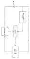
도 5, 도 6 및 도 7에 도시된 바와 같이, 상기 제어유닛의 Vo(C1)핀 출력이 1V이고, 방전전류가 1A이면, Vo(C1) 전위가 R2(C2), R3(C3)을 거쳐 분압된 후 VT(C4)=10mV가 된다. 이 때 R1(C5)을 거친 전류가 0.5A라고 가정하면, Vc(C6)=5mV이며, VT(C4)와 Vc(C6)가 OP(C7)를 거쳐 비교된 후 로우(Low)로 출력되면서, Q1(C8)이 OFF 상태로 나타나고, Q1(C8)이 OFF로 나타나는 동시에 MOS1(C9), MOS2(C10)가 동시에 ON이 되어, 방전대기 전류가 빠르게 상승할 가능성이 있으며, 전류가 1.1A로 상승하면, VCC(C11)가 11mV로 변하게 된다. OP(C7)가 수시로 끊임없이 Vc(C6)와 VT(C4)의 전압치를 비교하면서 확대되기 때문에, OP(C7)의 출력이 하이(High)로 변하게 되어, Q1(C8)이 ON을 나타내고, MOS1(C9), MOS2(C10)가 동시에 OFF가 되며, 방전 전류는 빠르게 하강하게 된다. 전류가 0.9A까지 하강하면 Vc(C6)= 9mV가 되 며, 또한 OP(C7)이 로우(Low)로 출력되고, Q1(C8)이 OFF로 나타나며, MOS1(C9), MOS2(C10)가 ON으로 나타나, 전류가 또다시 상승하게 된다. OP(C7)가 끊임없이 비교를 하기 때문에, Q1(C8) 역시 끊임없이 ON, OFF하게 되면서, MOS1(C9), MOS2(C10) 역시 ON, OFF하게 되며, 이와 같이 방전 전류에 고정 정전류가 형성된다. 따라서 제어유닛(C)을 설정하면, 배터리(H)가 어느 한 전압치까지 방전될 때 방전을 중지함과 동시에 방전시간을 기록하게 되며, 방전시간에 방전전류를 곱하면 상기 배터리(H)의 실제 유효용량이 된다.As shown in Figs. 5, 6 and 7, when the Vo (C1) pin output of the control unit is 1V and the discharge current is 1A, the Vo (C1) potentials are R2 (C2) and R3 (C3). after the partial pressure is through the V T (C4) = 10mV. If this time is assumed that the current rough R1 (C5) is 0.5A, Vc (C6) = 5mV and, after V T (C4) and Vc (C6) is compared via the OP (C7) output to a low (Low) Q1 (C8) turns OFF, Q1 (C8) turns OFF, and MOS1 (C9) and MOS2 (C10) turn ON simultaneously, which may cause the discharge standby current to rise rapidly. When it rises to A, VCC (C11) changes to 11 mV. Since the OP (C7) to expand while often constantly compare the voltage value of Vc (C6) and V T (C4), the output of OP (C7) is changed to a high (High), Q1 (C8) represents the ON, MOS1 (C9) and MOS2 (C10) are turned off at the same time, and the discharge current falls rapidly. When the current drops to 0.9A, Vc (C6) = 9mV, OP (C7) is output low, Q1 (C8) is OFF, MOS1 (C9), MOS2 (C10) Appears ON and the current rises again. Since OP (C7) constantly compares, Q1 (C8) is constantly turned on and off, and MOS1 (C9) and MOS2 (C10) are turned on and off as well. Thus, a fixed constant current is formed in the discharge current. Therefore, if the control unit (C) is set, when the battery (H) is discharged to any one voltage value, the discharge is stopped and at the same time recording the discharge time, multiplying the discharge time by the discharge current of the battery (H) It becomes the actual effective capacity.
이상에 설명한 내용은 본 발명의 실시 가능한 실시예로서, 본 기술을 숙지하는 자가 본 발명에 설명한 기술 및 방법을 이용하여 수식 또는 변경을 가하는 경우, 발명의 출원범위 내에 포함되는 것으로 간주한다.The above-described information is an exemplary embodiment of the present invention, and when a person skilled in the art adds an equation or a change by using the techniques and methods described in the present invention, it is considered to be included in the scope of the present invention.
도 1은 종래의 블록도이다.1 is a conventional block diagram.
도 2는 종래의 입체도이다.2 is a conventional stereoscopic view.
도 3은 본 발명의 블록도 1이다.3 is a block diagram 1 of the present invention.
도 4는 본 발명의 입체도이다.4 is a three-dimensional view of the present invention.
도 5는 본 발명의 블록도 2이다.5 is a block diagram 2 of the present invention.
도 6은 본 발명의 회로도이다.6 is a circuit diagram of the present invention.
도 7은 본 발명의 회로 블록도이다.7 is a circuit block diagram of the present invention.
<도면의 주요 부분에 대한 부호의 설명><Explanation of symbols for main parts of the drawings>
A:충전설비 A1: 배터리A: Charging Facility A1: Battery
A2: 충전기 A3: 방전기A2: Charger A3: Discharger
B: 충전장치 C: 제어유닛B: Charging Unit C: Control Unit
C1: Vo C2: R2C1: Vo C2: R2
C3: R3 C4: VT C3: R3 C4: V T
C5: R1 C6: VcC5: R1 C6: Vc
C7: OP C8: Q1C7: OP C8: Q1
C9: MOS1 C10: MOS2C9: MOS1 C10: MOS2
C11: VCC D:계산유닛C11: VCC D: Calculation Unit
E: 디스플레이유닛 E1: LCD 디스플레이장치E: Display unit E1: LCD display device
E2: LED 디스플레이장치 F: 충전유닛E2: LED Display F: Charging Unit
H1: 전도단자 I: 전원도통유닛H1: Conduction terminal I: Power supply unit
J: 메모리유닛 G: 방전유닛J: memory unit G: discharge unit
H: 배터리H: Battery
Claims (5)
Applications Claiming Priority (5)
| Application Number | Priority Date | Filing Date | Title |
|---|---|---|---|
| TW096115991A TW200845461A (en) | 2007-05-04 | 2007-05-04 | Recharging apparatus with battery capacity analyzing function |
| TW096115991 | 2007-05-04 | ||
| CN2007101283436A CN101079552B (en) | 2007-05-04 | 2007-06-27 | Charging device with battery capacity analysis function |
| US11/882,080 US20090033284A1 (en) | 2007-05-04 | 2007-07-30 | Charging device with battery capacity analysis function |
| DE102007038376A DE102007038376A1 (en) | 2007-05-04 | 2007-08-14 | Supercharger with function for determining battery capacity, has charging unit provided with control unit for charging battery and discharging unit is provided to discharge battery |
Publications (1)
| Publication Number | Publication Date |
|---|---|
| KR20080098323A true KR20080098323A (en) | 2008-11-07 |
Family
ID=49033658
Family Applications (1)
| Application Number | Title | Priority Date | Filing Date |
|---|---|---|---|
| KR1020080041233A Ceased KR20080098323A (en) | 2007-05-04 | 2008-05-02 | Charging device with battery capacity analysis |
Country Status (8)
| Country | Link |
|---|---|
| US (1) | US20090033284A1 (en) |
| JP (1) | JP2008278744A (en) |
| KR (1) | KR20080098323A (en) |
| CN (1) | CN101079552B (en) |
| DE (1) | DE102007038376A1 (en) |
| FR (1) | FR2915837A1 (en) |
| GB (1) | GB2448998B (en) |
| TW (1) | TW200845461A (en) |
Families Citing this family (5)
| Publication number | Priority date | Publication date | Assignee | Title |
|---|---|---|---|---|
| DE102010001712A1 (en) | 2010-02-09 | 2011-08-11 | Robert Bosch GmbH, 70469 | Method for charging a rechargeable energy store, charging device for a rechargeable energy store and circuit breaker |
| DE102013102461A1 (en) * | 2013-03-12 | 2014-09-18 | Evonik Industries Ag | Method for determining the state of charge of a rechargeable battery |
| US9954384B2 (en) | 2015-05-13 | 2018-04-24 | Nucleus Scientific Inc. | Instrumented super-cell |
| CN107093776A (en) * | 2017-04-11 | 2017-08-25 | 歌尔科技有限公司 | Auto-correction method and device, the battery and unmanned plane of battery |
| CN110061537A (en) * | 2019-03-15 | 2019-07-26 | 深圳易马达科技有限公司 | Change electric cabinet and its charging and discharging lithium battery control circuit, charging and discharging lithium battery system |
Family Cites Families (40)
| Publication number | Priority date | Publication date | Assignee | Title |
|---|---|---|---|---|
| US4413221A (en) * | 1980-12-18 | 1983-11-01 | Christie Electric Corporation | Method and circuit for determining battery capacity |
| US5278487A (en) * | 1988-03-15 | 1994-01-11 | Norand Corporation | Battery conditioning system having communication with battery parameter memory means in conjunction with battery conditioning |
| US5619117A (en) * | 1982-06-07 | 1997-04-08 | Norand Corporation | Battery pack having memory |
| US4709202A (en) * | 1982-06-07 | 1987-11-24 | Norand Corporation | Battery powered system |
| US4553081A (en) * | 1982-06-07 | 1985-11-12 | Norand Corporation | Portable battery powered system |
| US5889386A (en) * | 1982-06-07 | 1999-03-30 | Intermec Technology Corporation | Battery conditioning system having communication with battery parameter memory means in conjunction with battery conditioning |
| FR2537785A1 (en) * | 1982-12-13 | 1984-06-15 | Electricite De France | DEVICE FOR CONTROLLING THE CAPACITY OF A BATTERY OF ACCUMULATOR ELEMENTS |
| DE3325282C2 (en) * | 1983-07-13 | 1986-09-25 | Howmedica International, Inc., 2301 Schönkirchen | Procedure for charging an accumulator |
| EP0146377A1 (en) * | 1983-12-16 | 1985-06-26 | The Commonwealth Of Australia | Battery testing circuit |
| US6075340A (en) * | 1985-11-12 | 2000-06-13 | Intermec Ip Corp. | Battery pack having memory |
| JPS61170678A (en) * | 1985-01-25 | 1986-08-01 | Nissan Motor Co Ltd | Battery state detector |
| IT1219776B (en) * | 1988-03-02 | 1990-05-24 | Beghelli G P B Srl | CONTROL SYSTEM AND DIAGNOSIS OF THE STATE OF CARCIA OF THE BATTERIES ESPECIALLY FOR "CONTINUITY" GROUPS OF ELECTRIC POWER SUPPLY |
| JPH02119069A (en) * | 1988-10-28 | 1990-05-07 | Tokyo Electric Co Ltd | battery check device |
| US5032825A (en) * | 1990-03-02 | 1991-07-16 | Motorola, Inc. | Battery capacity indicator |
| US5284719A (en) * | 1992-07-08 | 1994-02-08 | Benchmarq Microelectronics, Inc. | Method and apparatus for monitoring battery capacity |
| US5440221A (en) * | 1992-07-08 | 1995-08-08 | Benchmarg Microelectronics, Inc. | Method and apparatus for monitoring batttery capacity with charge control |
| US5539318A (en) * | 1992-07-16 | 1996-07-23 | Toyota Jidosha Kabushiki Kaisha | Residual capacity meter for electric car battery |
| JP3251657B2 (en) * | 1992-08-27 | 2002-01-28 | 株式会社日立製作所 | Secondary battery device |
| JP3172977B2 (en) * | 1993-05-26 | 2001-06-04 | 富士重工業株式会社 | In-vehicle battery capacity meter |
| JP3285720B2 (en) * | 1994-11-08 | 2002-05-27 | 松下電器産業株式会社 | Method and apparatus for detecting deterioration of assembled battery |
| US5633573A (en) * | 1994-11-10 | 1997-05-27 | Duracell, Inc. | Battery pack having a processor controlled battery operating system |
| JPH08136628A (en) * | 1994-11-11 | 1996-05-31 | Fujitsu Ltd | Battery capacity monitor |
| JPH08233916A (en) * | 1995-02-28 | 1996-09-13 | Sanyo Electric Co Ltd | Battery inspecting method |
| US5705929A (en) * | 1995-05-23 | 1998-01-06 | Fibercorp. Inc. | Battery capacity monitoring system |
| US5656919A (en) * | 1995-11-14 | 1997-08-12 | Cruising Equipment, Inc. | Accurate battery state-of-charge monitoring and indicating apparatus and method |
| GB2326241A (en) * | 1997-06-10 | 1998-12-16 | Tony Smith | Instrument for measuring battery capacity |
| TW407212B (en) * | 1997-10-31 | 2000-10-01 | Toshiba Battery | Battery remaining capacity measuring device |
| DE29823530U1 (en) * | 1998-04-27 | 1999-08-12 | Siemens Nixdorf Informationssysteme AG, 33106 Paderborn | Circuit arrangement for discharging a like in a notebook computer. used rechargeable power source |
| US6051957A (en) * | 1998-10-21 | 2000-04-18 | Duracell Inc. | Battery pack having a state of charge indicator |
| JP2001006755A (en) * | 1999-06-18 | 2001-01-12 | Toshiba Corp | Battery capacity check device |
| JP3652191B2 (en) * | 1999-11-10 | 2005-05-25 | 株式会社マキタ | Charger |
| US6191559B1 (en) * | 2000-01-11 | 2001-02-20 | Lucent Technologies, Inc. | Battery capacity calculator and method of calculating battery capacity |
| US6307349B1 (en) * | 2000-02-24 | 2001-10-23 | Intermec Ip Corp. | Battery pack having memory |
| US6384608B1 (en) * | 2001-03-13 | 2002-05-07 | Actron Manufacturing Co. | Battery tester using internal resistance to measure a condition of a battery |
| JP4380932B2 (en) * | 2001-03-30 | 2009-12-09 | 三洋電機株式会社 | Calculation method of remaining battery capacity |
| JP3897230B2 (en) * | 2001-06-11 | 2007-03-22 | 株式会社タツノ・メカトロニクス | Battery diagnostic device |
| US20030184264A1 (en) * | 2002-03-28 | 2003-10-02 | Bertness Kevin I. | Apparatus and method for counteracting self discharge in a storage battery |
| US6771073B2 (en) * | 2002-01-04 | 2004-08-03 | Auto Meter Products, Inc. | Microprocessor-based hand-held electrical-testing system and method |
| US7492127B2 (en) * | 2005-01-07 | 2009-02-17 | Symbol Technologies, Inc. | System and method for battery calibration in portable computing devices |
| DE202006002864U1 (en) * | 2006-02-23 | 2006-05-04 | Scholz, Axel | Charging and testing device for electrical battery, has unit for measuring and/or recording electrical parameter of electrical battery charger that is attached by connection |
-
2007
- 2007-05-04 TW TW096115991A patent/TW200845461A/en unknown
- 2007-06-27 CN CN2007101283436A patent/CN101079552B/en not_active Expired - Fee Related
- 2007-07-30 US US11/882,080 patent/US20090033284A1/en not_active Abandoned
- 2007-08-14 DE DE102007038376A patent/DE102007038376A1/en not_active Ceased
-
2008
- 2008-04-30 FR FR0802432A patent/FR2915837A1/en not_active Withdrawn
- 2008-05-02 KR KR1020080041233A patent/KR20080098323A/en not_active Ceased
- 2008-05-02 JP JP2008120741A patent/JP2008278744A/en active Pending
- 2008-05-06 GB GB0808225A patent/GB2448998B/en not_active Expired - Fee Related
Also Published As
| Publication number | Publication date |
|---|---|
| JP2008278744A (en) | 2008-11-13 |
| CN101079552A (en) | 2007-11-28 |
| GB0808225D0 (en) | 2008-06-11 |
| GB2448998B (en) | 2010-10-13 |
| TW200845461A (en) | 2008-11-16 |
| CN101079552B (en) | 2012-05-30 |
| DE102007038376A1 (en) | 2009-02-26 |
| US20090033284A1 (en) | 2009-02-05 |
| GB2448998A (en) | 2008-11-05 |
| FR2915837A1 (en) | 2008-11-07 |
Similar Documents
| Publication | Publication Date | Title |
|---|---|---|
| CN101872988B (en) | Battery pack | |
| US8159185B2 (en) | Battery charger and control method therefor | |
| US8149556B2 (en) | Power adapter and power supply method thereof | |
| JP2007143284A (en) | Battery pack for power tools | |
| JP4715123B2 (en) | Lead storage battery state detection device and lead storage battery integrally provided with the state detection device | |
| CN101141077A (en) | Battery control device, battery control method, power source control device and electronic device | |
| JP3980509B2 (en) | Secondary battery device | |
| US20120056480A1 (en) | Control device, electronic apparatus, timepiece device, and control method | |
| KR20080098323A (en) | Charging device with battery capacity analysis | |
| CN114072984B (en) | Battery management apparatus | |
| JP4415131B2 (en) | Battery protection device and battery protection circuit | |
| CN101499656A (en) | Power supply circuit having resistance element changing its resistance value | |
| US6922151B2 (en) | Battery remaining amount warning circuit | |
| JP4137011B2 (en) | Charge control circuit, battery pack, and electronic device | |
| Bansal et al. | Battery performance tester for lithium-ion technology with Arduino Uno & MCP | |
| CN107615563A (en) | Device for judging state of battery for auxiliary equipment and method for judging state of battery for auxiliary machinery | |
| JP2016201934A (en) | Deterioration detection device and deterioration detection method of power supply device | |
| US7525282B2 (en) | Battery-operated equipment including a microcomputer | |
| JP6468148B2 (en) | Electronic control unit | |
| JP2006296019A (en) | Power supply | |
| TWI392188B (en) | 2 times battery pack system | |
| KR101426502B1 (en) | Guiding System For Battery Recoverying Time | |
| JP4577502B2 (en) | Battery control circuit and electronic device provided with the battery control circuit | |
| JPH08213059A (en) | Electronics | |
| JP5361050B2 (en) | Charging device and battery driving device |
Legal Events
| Date | Code | Title | Description |
|---|---|---|---|
| A201 | Request for examination | ||
| PA0109 | Patent application |
St.27 status event code: A-0-1-A10-A12-nap-PA0109 |
|
| PA0201 | Request for examination |
St.27 status event code: A-1-2-D10-D11-exm-PA0201 |
|
| P11-X000 | Amendment of application requested |
St.27 status event code: A-2-2-P10-P11-nap-X000 |
|
| P13-X000 | Application amended |
St.27 status event code: A-2-2-P10-P13-nap-X000 |
|
| PG1501 | Laying open of application |
St.27 status event code: A-1-1-Q10-Q12-nap-PG1501 |
|
| D13-X000 | Search requested |
St.27 status event code: A-1-2-D10-D13-srh-X000 |
|
| D14-X000 | Search report completed |
St.27 status event code: A-1-2-D10-D14-srh-X000 |
|
| E902 | Notification of reason for refusal | ||
| PE0902 | Notice of grounds for rejection |
St.27 status event code: A-1-2-D10-D21-exm-PE0902 |
|
| P11-X000 | Amendment of application requested |
St.27 status event code: A-2-2-P10-P11-nap-X000 |
|
| P13-X000 | Application amended |
St.27 status event code: A-2-2-P10-P13-nap-X000 |
|
| E601 | Decision to refuse application | ||
| PE0601 | Decision on rejection of patent |
St.27 status event code: N-2-6-B10-B15-exm-PE0601 |
|
| P22-X000 | Classification modified |
St.27 status event code: A-2-2-P10-P22-nap-X000 |
|
| P22-X000 | Classification modified |
St.27 status event code: A-2-2-P10-P22-nap-X000 |
|
| P22-X000 | Classification modified |
St.27 status event code: A-2-2-P10-P22-nap-X000 |
|
| P22-X000 | Classification modified |
St.27 status event code: A-2-2-P10-P22-nap-X000 |