JP2013236492A - Battery module and battery management system - Google Patents
Battery module and battery management system Download PDFInfo
- Publication number
- JP2013236492A JP2013236492A JP2012107909A JP2012107909A JP2013236492A JP 2013236492 A JP2013236492 A JP 2013236492A JP 2012107909 A JP2012107909 A JP 2012107909A JP 2012107909 A JP2012107909 A JP 2012107909A JP 2013236492 A JP2013236492 A JP 2013236492A
- Authority
- JP
- Japan
- Prior art keywords
- power
- circuit
- battery
- current
- value
- Prior art date
- Legal status (The legal status is an assumption and is not a legal conclusion. Google has not performed a legal analysis and makes no representation as to the accuracy of the status listed.)
- Pending
Links
- 238000001514 detection method Methods 0.000 claims abstract description 141
- 238000000034 method Methods 0.000 claims description 49
- 238000012545 processing Methods 0.000 claims description 24
- 238000007599 discharging Methods 0.000 claims description 8
- 230000005611 electricity Effects 0.000 abstract description 22
- 238000004891 communication Methods 0.000 description 35
- 238000006243 chemical reaction Methods 0.000 description 10
- 238000010586 diagram Methods 0.000 description 7
- 238000007689 inspection Methods 0.000 description 5
- 230000006866 deterioration Effects 0.000 description 4
- 238000012360 testing method Methods 0.000 description 3
- HBBGRARXTFLTSG-UHFFFAOYSA-N Lithium ion Chemical compound [Li+] HBBGRARXTFLTSG-UHFFFAOYSA-N 0.000 description 2
- 230000006870 function Effects 0.000 description 2
- 229910001416 lithium ion Inorganic materials 0.000 description 2
- 238000012544 monitoring process Methods 0.000 description 2
- 230000002093 peripheral effect Effects 0.000 description 2
- PXHVJJICTQNCMI-UHFFFAOYSA-N Nickel Chemical compound [Ni] PXHVJJICTQNCMI-UHFFFAOYSA-N 0.000 description 1
- 238000010521 absorption reaction Methods 0.000 description 1
- 230000005540 biological transmission Effects 0.000 description 1
- 238000012937 correction Methods 0.000 description 1
- 230000007423 decrease Effects 0.000 description 1
- 230000005669 field effect Effects 0.000 description 1
- 238000004519 manufacturing process Methods 0.000 description 1
- 229910000652 nickel hydride Inorganic materials 0.000 description 1
- 238000010248 power generation Methods 0.000 description 1
- 230000004044 response Effects 0.000 description 1
Images


Classifications
-
- Y—GENERAL TAGGING OF NEW TECHNOLOGICAL DEVELOPMENTS; GENERAL TAGGING OF CROSS-SECTIONAL TECHNOLOGIES SPANNING OVER SEVERAL SECTIONS OF THE IPC; TECHNICAL SUBJECTS COVERED BY FORMER USPC CROSS-REFERENCE ART COLLECTIONS [XRACs] AND DIGESTS
- Y02—TECHNOLOGIES OR APPLICATIONS FOR MITIGATION OR ADAPTATION AGAINST CLIMATE CHANGE
- Y02E—REDUCTION OF GREENHOUSE GAS [GHG] EMISSIONS, RELATED TO ENERGY GENERATION, TRANSMISSION OR DISTRIBUTION
- Y02E60/00—Enabling technologies; Technologies with a potential or indirect contribution to GHG emissions mitigation
- Y02E60/10—Energy storage using batteries
Landscapes
- Charge And Discharge Circuits For Batteries Or The Like (AREA)
- Secondary Cells (AREA)
- Battery Mounting, Suspending (AREA)
Abstract
Description
本発明は、二次電池を含む電池モジュール、及びその電池モジュールを複数含む電池管理システムに関する。 The present invention relates to a battery module including a secondary battery and a battery management system including a plurality of the battery modules.
近年、エンジンと電気モータとを併用したハイブリッドカーや電気自動車に電源として搭載される車載用二次電池に代表されるように、二次電池を多数接続して高電圧を出力する電源システムの利用が拡大しつつある。このような電源システムは、例えば80セル〜500セルといった多数の二次電池が直列接続されて構成されているため、電源システム全体の信頼性を確保する事が難しい。 In recent years, the use of a power supply system that outputs a high voltage by connecting a large number of secondary batteries, as typified by in-vehicle secondary batteries that are mounted as power sources in hybrid cars and electric vehicles that use an engine and an electric motor together Is expanding. Since such a power supply system is configured by connecting a large number of secondary batteries, for example, 80 cells to 500 cells, in series, it is difficult to ensure the reliability of the entire power supply system.
具体的には、このような電源システムでは、電源システムを構成している二次電池の製造過程で発生する特性バラツキによって、各二次電池に充電される蓄電電気量(蓄電電荷量)にバラツキが生じる。 Specifically, in such a power supply system, the amount of stored electricity (charged charge amount) charged in each secondary battery varies due to characteristic variations that occur during the manufacturing process of the secondary battery that constitutes the power supply system. Occurs.
そして、このような蓄電電気量にバラツキのある状態で電源システムの充放電を繰り返すと、蓄電電気量が小さな二次電池の劣化が加速されるおそれがある。すなわち、電源システムを充電する際、充電前から他の二次電池より蓄電電気量が大きい二次電池は他の二次電池より先に満充電となるために過充電になり易く、蓄電電気量が大きい二次電池の劣化が加速されてしまうおそれがある。一方、電源システムを放電させる際は、放電前から他の二次電池より蓄電電気量が小さい二次電池は他の二次電池より先に蓄電電気量がゼロになるために過放電になり易く、蓄電電気量が小さい二次電池劣化が加速されてしまうおそれがある。 And if charging / discharging of a power supply system is repeated in the state in which the amount of stored electricity varies, there is a risk that the deterioration of a secondary battery with a small amount of stored electricity will be accelerated. That is, when charging a power supply system, a secondary battery having a larger amount of stored electricity than other secondary batteries before charging is likely to be overcharged because it is fully charged before other secondary batteries. There is a possibility that the deterioration of the secondary battery having a large size may be accelerated. On the other hand, when discharging the power supply system, secondary batteries that have a smaller amount of stored electricity than other secondary batteries before discharge tend to be over-discharged because the stored amount of electricity is zero before other secondary batteries. There is a possibility that the deterioration of the secondary battery with a small amount of electricity stored will be accelerated.
そして、劣化が加速された二次電池は、容量が減少して寿命が短縮されることとなる。電源システムの場合、一部の二次電池が劣化すると、電源システム全体が使用できなくなったり信頼性が低下したりするため、このような蓄電電気量のバラツキに起因して生じる二次電池の劣化は影響が大きい。そのため、二次電池を多数用いる電源システムでは、各二次電池の蓄電電気量を均等化すること、すなわち各二次電池の端子電圧を均等化することが望まれている。 The secondary battery whose deterioration has been accelerated has a reduced capacity and a shortened life. In the case of a power supply system, if some secondary batteries deteriorate, the entire power supply system becomes unusable or decreases in reliability. Has a great impact. Therefore, in a power supply system that uses a large number of secondary batteries, it is desired to equalize the amount of electricity stored in each secondary battery, that is, equalize the terminal voltage of each secondary battery.
一方、二次電池を用いる場合、二次電池の蓄電電気量を求めたり、安全性を向上させたりするために、制御回路を設けて二次電池の端子電圧や温度等を検出したり、監視したりして、二次電池を管理することが広く行われている。しかしながら、上述のように、数十個から数百個に及ぶ多数の二次電池セルを用いる場合、すべての二次電池を一つの制御回路で管理することは容易でない。 On the other hand, when a secondary battery is used, a control circuit is provided to detect or monitor the terminal voltage, temperature, etc. of the secondary battery in order to obtain the amount of electricity stored in the secondary battery or improve safety. For example, managing secondary batteries is widely performed. However, as described above, when a large number of secondary battery cells ranging from several tens to several hundreds are used, it is not easy to manage all the secondary batteries with one control circuit.
そこで、多数の二次電池を複数のモジュールに分割し、モジュール毎に制御回路を設けることで、多数の二次電池の温度や電圧などの監視を容易にする技術が知られている。このような構成では、各モジュール内で消費される電源電流は、各モジュールに含まれる二次電池から供給されることになる。 Therefore, a technique is known in which a large number of secondary batteries are divided into a plurality of modules, and a control circuit is provided for each module, thereby facilitating monitoring of the temperatures and voltages of the numerous secondary batteries. In such a configuration, the power supply current consumed in each module is supplied from the secondary battery included in each module.
しかしながら、各モジュールに含まれる制御回路等の特性ばらつきによって、各モジュールの消費電流相互間には、わずかながら差が生じる。各モジュールは常時二次電池の出力電流を消費し続ける。そのため、例えわずかであっても各モジュール相互間の消費電流に差があると、各モジュール間で二次電池の蓄電電気量の差が徐々に蓄積されていき、各モジュール相互間での蓄電電気量に不均衡が生じるという不都合があった。 However, there is a slight difference between the consumption currents of the modules due to variations in the characteristics of control circuits and the like included in the modules. Each module always consumes the output current of the secondary battery. For this reason, even if there is a slight difference in the current consumption between the modules, the difference in the amount of electricity stored in the secondary battery gradually accumulates between the modules. There was the inconvenience that an imbalance occurred in quantity.
そこで、各モジュールに二次電池を強制的に放電させる放電回路を備え、各モジュールに設けられた監視ICの消費電流の差に相当する電流を、各モジュールの放電回路で放電させることによって、各モジュール相互間で蓄電電気量に不均衡が生じることを防止する技術が知られている(例えば、特許文献1参照)。 Therefore, each module is provided with a discharge circuit that forcibly discharges the secondary battery, and each module discharges a current corresponding to the difference in consumption current of the monitoring IC provided in each module by each discharge circuit. A technique for preventing an imbalance in the amount of stored electricity between modules is known (see, for example, Patent Document 1).
しかしながら、上述の技術によれば、各モジュール相互間の消費電流の差を吸収させる目的のために、複数のモジュールに、二次電池を強制的に放電させ、かつその放電量を調節可能な放電回路を備える必要があるため、コストが増大するという不都合があった。 However, according to the above-described technique, for the purpose of absorbing the difference in current consumption between the modules, the secondary battery is forcibly discharged to a plurality of modules and the discharge amount is adjustable. Since it is necessary to provide a circuit, there is a disadvantage that the cost increases.
本発明の目的は、各モジュール相互間の消費電流の差を吸収させる目的のためだけに放電回路を備えることなく、各モジュール相互間の消費電流の差に起因する二次電池の蓄電電気量の不均衡が、生じるおそれを低減することができる電池モジュール、及びこの電池モジュールを複数含む電池管理システムを提供することである。 The object of the present invention is to provide an amount of stored electricity of a secondary battery caused by a difference in consumption current between modules without providing a discharge circuit only for the purpose of absorbing the difference in consumption current between modules. To provide a battery module capable of reducing the possibility of imbalance and a battery management system including a plurality of the battery modules.
本発明に係る電池モジュールは、二次電池を含む電池モジュールであって、前記二次電池から供給された電力に基づく電源電流によって、前記二次電池を放電させる目的とは異なる目的の処理を行う電流消費回路と、前記電流消費回路へ供給される電源電流をオンオフする電流開閉部と、前記二次電池から供給された電力に基づき動作する制御部と、前記電池モジュールの消費電力に関する消費電力情報を予め記憶する記憶部とを備え、前記制御部は、前記電流開閉部によって前記電源電流をオンオフさせることによって前記二次電池から前記電流消費回路へ供給される電力の平均値を、所定の目標電力と前記消費電力情報に基づく消費電力との差に相当する差分電力と実質的に等しくさせる前記オンオフのデューティ比を取得するデューティ比取得部と、前記電流消費回路によって前記処理が実行される期間中、前記電流開閉部によって前記電源電流をオンさせ、前記電流消費回路によって前記処理が実行されないとき、前記電流開閉部によって前記電源電流を前記デューティ比でオンオフさせる電源制御部とを含む。 The battery module according to the present invention is a battery module including a secondary battery, and performs processing for a purpose different from the purpose of discharging the secondary battery by a power supply current based on power supplied from the secondary battery. A current consuming circuit; a current switching unit for turning on and off a power supply current supplied to the current consuming circuit; a control unit that operates based on power supplied from the secondary battery; and power consumption information relating to power consumption of the battery module And a storage unit that stores in advance, the control unit sets an average value of power supplied from the secondary battery to the current consumption circuit by turning on and off the power supply current by the current switching unit. The duty cycle for obtaining the on / off duty ratio that is substantially equal to the differential power corresponding to the difference between the power and the power consumption based on the power consumption information. During the period when the processing is executed by the ratio acquisition unit and the current consumption circuit, the power switch is turned on by the current switching unit, and when the processing is not performed by the current consumption circuit, the current switching unit And a power supply controller that turns on and off the current at the duty ratio.
この構成によれば、二次電池を放電させる目的とは異なる目的の処理を行う電流消費回路、すなわち、二次電池を放電させることのみを目的とする回路ではない電流消費回路を備える。また、記憶部に、電池モジュールの消費電力に関する消費電力情報が予め記憶されている。そして、デューティ比取得部は、電流開閉部によって、電流消費回路へ供給される電源電流をオンオフさせることにより電流消費回路へ供給される電力の平均値を、所定の目標電力と消費電力情報に基づく消費電力との差に相当する差分電力と実質的に等しくさせるオンオフのデューティ比を取得する。電源制御部は、電流消費回路によって前記処理が実行される期間中、電流開閉部によって電源電流をオンさせ、電流消費回路へ電源電流を供給させるので、電流消費回路は、前記処理を実行することができる。また、電流消費回路によって前記処理が実行されないとき、電源制御部は、電流開閉部によって電流消費回路に供給される電源電流を、デューティ比取得部により取得されたデューティ比でオンオフさせる。これにより、電源制御部は、電源電流をオンオフさせることによって二次電池から電流消費回路へ供給される電力の平均値を、目標電力と消費電力情報に基づく消費電力との差に相当する差分電力と実質的に等しくさせる。その結果、電流消費回路を含む電池モジュール全体の消費電力が、目標電力と実質的に等しくなる。そうすると、複数の電池モジュールの消費電力(消費電流)にばらつきが有った場合であっても、各電池モジュールにおける消費電力が目標電力と等しくされる結果、各電池モジュールにおける二次電池の放電電流が略等しくなる。その結果、各モジュール相互間の消費電流の差を吸収させる目的のためだけに放電回路を備えることなく、各モジュール相互間の消費電流の差に起因する二次電池の蓄電電気量の不均衡が生じるおそれを低減することができる。 According to this configuration, a current consumption circuit that performs processing for a purpose different from the purpose of discharging the secondary battery, that is, a current consumption circuit that is not a circuit intended only for discharging the secondary battery is provided. Further, power consumption information related to the power consumption of the battery module is stored in the storage unit in advance. Then, the duty ratio acquisition unit turns on and off the power supply current supplied to the current consumption circuit by the current opening / closing unit, and based on the predetermined target power and the power consumption information, the average value of the power supplied to the current consumption circuit An on / off duty ratio that is substantially equal to the difference power corresponding to the difference from the power consumption is acquired. Since the power control unit turns on the power supply current by the current switching unit and supplies the power supply current to the current consumption circuit during the period in which the process is executed by the current consumption circuit, the current consumption circuit executes the process. Can do. Further, when the processing is not executed by the current consumption circuit, the power supply control unit turns on and off the power supply current supplied to the current consumption circuit by the current switching unit at the duty ratio acquired by the duty ratio acquisition unit. As a result, the power supply control unit sets the average power supplied from the secondary battery to the current consumption circuit by turning on and off the power supply current as the difference power corresponding to the difference between the target power and the power consumption based on the power consumption information. And substantially equal. As a result, the power consumption of the entire battery module including the current consumption circuit is substantially equal to the target power. As a result, even if there is a variation in the power consumption (current consumption) of the plurality of battery modules, the power consumption in each battery module is made equal to the target power, resulting in the discharge current of the secondary battery in each battery module. Are substantially equal. As a result, there is no imbalance in the amount of electricity stored in the secondary battery due to the difference in current consumption between the modules without providing a discharge circuit only for the purpose of absorbing the current consumption difference between the modules. The risk of occurrence can be reduced.
また、前記電流消費回路は、前記二次電池の温度を検出するサーミスタと、前記サーミスタに直列に接続され、かつ予め設定された抵抗値を有する直列抵抗とを含む温度検出回路を含み、前記温度検出回路の処理は、前記直列抵抗と前記サーミスタとの直列回路を前記電源電流が流れることにより前記直列抵抗と前記サーミスタとの接続点に生じる電圧を、前記二次電池の温度を示す温度情報として出力する温度検出処理であることが好ましい。 The current consumption circuit includes a temperature detection circuit including a thermistor for detecting a temperature of the secondary battery, and a series resistor connected in series to the thermistor and having a preset resistance value, The processing of the detection circuit includes, as temperature information indicating a temperature of the secondary battery, a voltage generated at a connection point between the series resistor and the thermistor due to the supply current flowing through the series circuit of the series resistor and the thermistor. It is preferable that the temperature detection process be performed.
この構成によれば、二次電池の温度を検出する温度検出回路を、各モジュール相互間の消費電流の差に起因する二次電池の蓄電電気量の不均衡を低減させるための電流消費回路として用いることができる。 According to this configuration, the temperature detection circuit that detects the temperature of the secondary battery is used as a current consumption circuit for reducing an imbalance in the amount of electricity stored in the secondary battery due to a difference in current consumption between the modules. Can be used.
また、前記デューティ比取得部は、前記温度検出回路によって前記処理が実行されることにより出力された前記温度情報と、前記目標電力と、前記消費電力情報とに基づいて、前記平均値が前記差分電力となるように、前記オンオフのデューティ比を求めることが好ましい。 The duty ratio acquisition unit may calculate the difference between the average value based on the temperature information, the target power, and the power consumption information that are output when the processing is performed by the temperature detection circuit. It is preferable to obtain the on / off duty ratio so as to obtain electric power.
温度検出回路に含まれるサーミスタは、温度によって抵抗値が変化する。サーミスタの抵抗値が変化すると、サーミスタと直列抵抗との直列回路に流れる電流が変化する。そうすると、温度によって、温度検出回路において消費される電力が変化することになる。そこで、デューティ比取得部は、サーミスタの抵抗値の変化が反映された温度情報と、目標電力と、電池モジュールの消費電力に関する消費電力情報とに基づいて、電流消費回路へ供給される電力の平均値を、目標電力と消費電力情報に基づく消費電力との差に相当する差分電力と実質的に等しくさせるオンオフのデューティ比を求める。これにより、温度の変化によるサーミスタの抵抗値の変化を考慮して、前記デューティ比を求めることができるので、電流消費回路へ供給される電力の平均値を、目標電力と消費電力情報に基づく消費電力との差に相当する差分電力と実質的に等しくさせる精度が向上する。 The thermistor included in the temperature detection circuit changes its resistance value depending on the temperature. When the resistance value of the thermistor changes, the current flowing through the series circuit of the thermistor and the series resistor changes. Then, the electric power consumed in the temperature detection circuit changes depending on the temperature. Therefore, the duty ratio acquisition unit calculates the average power supplied to the current consumption circuit based on the temperature information reflecting the change in the resistance value of the thermistor, the target power, and the power consumption information regarding the power consumption of the battery module. An on / off duty ratio that makes the value substantially equal to the difference power corresponding to the difference between the target power and the power consumption based on the power consumption information is obtained. As a result, the duty ratio can be obtained in consideration of a change in the resistance value of the thermistor due to a change in temperature. Therefore, the average value of the power supplied to the current consumption circuit is calculated based on the target power and the power consumption information. The accuracy of making the difference power substantially equal to the difference from the power is improved.
また、前記電流消費回路は、前記二次電池の端子電圧を分圧する第1及び第2分圧抵抗を含む電圧検出回路を含み、前記電圧検出回路の処理は、前記第1及び第2分圧抵抗の直列回路を前記電源電流が流れることにより前記第1及び第2分圧抵抗によって分圧された電圧を、前記二次電池の端子電圧を示す電池電圧情報として出力する電圧検出処理であることが好ましい。 The current consumption circuit includes a voltage detection circuit including first and second voltage dividing resistors that divide the terminal voltage of the secondary battery, and the processing of the voltage detection circuit includes the first and second voltage divisions. A voltage detection process for outputting, as battery voltage information indicating a terminal voltage of the secondary battery, a voltage divided by the first and second voltage dividing resistors when the power supply current flows through a series circuit of resistors; Is preferred.
この構成によれば、二次電池の端子電圧を検出する電圧検出回路を、各モジュール相互間の消費電流の差に起因する二次電池の蓄電電気量の不均衡を低減させるための電流消費回路として用いることができる。 According to this configuration, the voltage detection circuit for detecting the terminal voltage of the secondary battery is a current consumption circuit for reducing an imbalance in the amount of electricity stored in the secondary battery due to the difference in current consumption between the modules. Can be used as
また、前記デューティ比取得部は、前記電圧検出回路によって前記処理が実行されることにより出力された前記電池電圧情報と、前記目標電力と、前記消費電力情報とに基づいて、前記平均値が前記差分電力となるように、前記オンオフのデューティ比を求めることが好ましい。 The duty ratio acquisition unit may calculate the average value based on the battery voltage information, the target power, and the power consumption information that are output when the processing is executed by the voltage detection circuit. It is preferable to obtain the on / off duty ratio so as to obtain differential power.
第1及び第2分圧抵抗の直列回路を流れる電源電流は、二次電池の端子電圧が変化すると変化する。そのため、電圧検出回路で消費される電力は、二次電池の端子電圧によって変化する。そこで、デューティ比取得部は、二次電池の端子電圧を示す電池電圧情報と、目標電力と、電池モジュールの消費電力に関する消費電力情報とに基づいて、電流消費回路へ供給される電力の平均値を、目標電力と消費電力情報に基づく消費電力との差に相当する差分電力と実質的に等しくさせるオンオフのデューティ比を求める。これにより、二次電池の端子電圧の変化による電圧検出回路の消費電力の変化を考慮して、前記デューティ比を求めることができるので、電流消費回路へ供給される電力の平均値を、目標電力と消費電力情報に基づく消費電力との差に相当する差分電力と実質的に等しくさせる精度が向上する。 The power supply current flowing through the series circuit of the first and second voltage dividing resistors changes when the terminal voltage of the secondary battery changes. Therefore, the power consumed by the voltage detection circuit varies depending on the terminal voltage of the secondary battery. Therefore, the duty ratio acquisition unit calculates the average value of the power supplied to the current consumption circuit based on the battery voltage information indicating the terminal voltage of the secondary battery, the target power, and the power consumption information regarding the power consumption of the battery module. Is determined to be substantially equal to the difference power corresponding to the difference between the target power and the power consumption based on the power consumption information. As a result, the duty ratio can be obtained in consideration of the change in power consumption of the voltage detection circuit due to the change in the terminal voltage of the secondary battery, so that the average value of the power supplied to the current consumption circuit can be calculated as the target power. The accuracy of making the difference power substantially equal to the difference between the power consumption based on the power consumption information and the power consumption based on the power consumption information is improved.
また、前記制御部と前記電流消費回路の少なくとも一部と前記電流開閉部とは、単一の集積回路に集積されており、前記電流開閉部は、前記制御部からの指示に応じて前記電流消費回路へ供給される電源電流をオフする省電力回路を含むことが好ましい。 In addition, the control unit, at least a part of the current consumption circuit, and the current switching unit are integrated in a single integrated circuit, and the current switching unit is configured to respond to an instruction from the control unit. It is preferable to include a power saving circuit that turns off the power supply current supplied to the consumption circuit.
この構成によれば、制御部と電流消費回路の少なくとも一部は、集積回路に集積されており、省電力回路によって、電流消費回路へ供給される電源電流をオンオフさせることができるので、集積回路内の回路ブロックを電流消費回路として用いることができる。 According to this configuration, at least a part of the control unit and the current consumption circuit is integrated in the integrated circuit, and the power supply current supplied to the current consumption circuit can be turned on and off by the power saving circuit. The inner circuit block can be used as a current consumption circuit.
また、前記制御部と前記電流消費回路と前記電流開閉部とは、単一の集積回路に集積されており、前記電流開閉部は、前記制御部からの指示に応じて前記電流消費回路へ供給される電源電流をオフする省電力回路を含むことが好ましい。 The control unit, the current consumption circuit, and the current switching unit are integrated in a single integrated circuit, and the current switching unit is supplied to the current consumption circuit in response to an instruction from the control unit. It is preferable to include a power saving circuit for turning off the power supply current.
この構成によれば、制御部と電流消費回路と電流開閉部とが一つの集積回路に集積されている。そして、省電力回路によって、電流消費回路へ供給される電源電流をオンオフさせることができるので、集積回路内の回路ブロックを電流消費回路として用いることができる。 According to this configuration, the control unit, the current consumption circuit, and the current switching unit are integrated in one integrated circuit. Since the power saving circuit can turn on and off the power supply current supplied to the current consumption circuit, the circuit block in the integrated circuit can be used as the current consumption circuit.
また、前記記憶部は、さらに、前記消費電力のばらつき範囲における上限値に相当する電力以上の値を、前記目標電力として予め記憶することが好ましい。 Moreover, it is preferable that the said storage part further memorize | stores previously the value more than the electric power equivalent to the upper limit in the variation range of the said power consumption as said target electric power.
この構成によれば、複数の電池モジュールが用いられる場合、各電池モジュールは、自律的に各電池モジュールの消費電力を目標電力と実質的に同一にさせることができる。従って、外部から目標電力を受信するための通信回路を備えたり、外部から目標電力を受信する処理を実行したりしなくても、各電池モジュールの自律的な動作によって、制御回路の消費電流の差に起因する二次電池の蓄電電気量の不均衡が生じるおそれを低減することができる。 According to this configuration, when a plurality of battery modules are used, each battery module can autonomously make the power consumption of each battery module substantially the same as the target power. Therefore, the current consumption of the control circuit can be reduced by the autonomous operation of each battery module without providing a communication circuit for receiving the target power from the outside or executing the process of receiving the target power from the outside. It is possible to reduce the possibility that an imbalance in the amount of electricity stored in the secondary battery due to the difference will occur.
また、本発明に係る電池管理システムは、上述の電池モジュールを複数含み、前記複数の電池モジュールにおける前記記憶部から前記消費電力情報をそれぞれ取得し、前記取得された各消費電力情報が示す前記消費電力のうち、最も大きな消費電力を前記目標電力として、その目標電力を示す情報を前記各電池モジュールの前記デューティ比取得部へ出力するシステム制御部を備える。 Moreover, the battery management system according to the present invention includes a plurality of the battery modules described above, acquires the power consumption information from the storage unit in the plurality of battery modules, and indicates the consumption indicated by the acquired power consumption information. The system control part which outputs the information which shows the largest power consumption among the electric power as the said target electric power to the said duty ratio acquisition part of each said battery module is provided.
この構成によれば、電池管理システムに含まれる複数の電池モジュールの制御部の消費電力のうち、最も大きな消費電力が、目標電力となる。そして、各電池モジュールにおける消費電力がその目標電力と実質的に同一となるように、デューティ比取得部によって取得されたデューティ比で、電流消費回路へ供給される電源電流がオンオフされる。その結果、消費電力が最大の電池モジュールでは、自モジュールの消費電力が目標電力と等しくなるから、電流消費回路で電力消費させる必要がなくなる結果、電力消費を低減できる。また、消費電力が最大の電池モジュール以外の電池モジュールは、電流消費回路で消費させる電力を必要最小限にすることができるので、電池管理システム全体の消費電力を低減することが容易である。 According to this configuration, the largest power consumption among the power consumption of the control units of the plurality of battery modules included in the battery management system is the target power. Then, the power supply current supplied to the current consumption circuit is turned on / off at the duty ratio acquired by the duty ratio acquisition unit so that the power consumption in each battery module is substantially the same as the target power. As a result, in the battery module with the maximum power consumption, the power consumption of the own module becomes equal to the target power, so that it is not necessary to consume the power in the current consumption circuit, so that the power consumption can be reduced. In addition, the battery modules other than the battery module with the largest power consumption can minimize the power consumed by the current consumption circuit, so that it is easy to reduce the power consumption of the entire battery management system.
また、本発明に係る電池管理システムは、上述の電池モジュールを複数含む電池管理システムである。 The battery management system according to the present invention is a battery management system including a plurality of the above-described battery modules.
この構成によれば、電池管理システムに含まれる複数の電池モジュールにおいて、各モジュール相互間の消費電流の差を吸収させる目的のためだけに放電回路を備えることなく、各モジュール相互間の消費電流の差に起因する二次電池の蓄電電気量の不均衡が生じるおそれを低減することができる。 According to this configuration, in the plurality of battery modules included in the battery management system, the current consumption between the modules can be reduced without providing the discharge circuit only for the purpose of absorbing the difference in current consumption between the modules. It is possible to reduce the possibility that an imbalance in the amount of electricity stored in the secondary battery due to the difference will occur.
このような構成の電池モジュール及び電池管理システムは、各電池モジュールにおける制御部と、二次電池を放電させる目的とは異なる目的の処理を行う電流消費回路とで消費される電力を目標電力と実質的に等しくできるので、複数の電池モジュール相互間の消費電力の差が低減される結果、各モジュール相互間の消費電流の差を吸収させる目的のためだけに放電回路を備えることなく、各モジュール相互間の消費電流の差に起因する二次電池の蓄電電気量の不均衡が、生じるおそれを低減することができる。 In the battery module and the battery management system having such a configuration, the power consumed by the control unit in each battery module and the current consumption circuit that performs processing for a purpose different from the purpose for discharging the secondary battery is substantially equal to the target power. As a result, the difference in power consumption among the plurality of battery modules is reduced, so that the modules can be connected to each other without providing a discharge circuit only for the purpose of absorbing the difference in current consumption between the modules. The possibility that an imbalance in the amount of electricity stored in the secondary battery due to the difference in current consumption between the secondary batteries may be reduced.
以下、本発明に係る実施形態を図面に基づいて説明する。なお、各図において同一の符号を付した構成は、同一の構成であることを示し、その説明を省略する。 Embodiments according to the present invention will be described below with reference to the drawings. In addition, the structure which attached | subjected the same code | symbol in each figure shows that it is the same structure, The description is abbreviate | omitted.
図1は、本発明の一実施形態に係る電池モジュールM1〜M3を備えた電池管理システム1の構成の一例を示すブロック図である。図1に示す電池管理システム1は、主ECU(Electronic Control Unit)2と、例えば3個の電池モジュールM1〜M3と、外部接続端子T(+),T(−)と、通信線Lとを備えている。なお、電池モジュールの個数は、2個であってもよく、3を超える数であってもよい。
FIG. 1 is a block diagram illustrating an example of a configuration of a
以下、電池モジュールM1〜M3を総称して電池モジュールMと称する。 Hereinafter, the battery modules M1 to M3 are collectively referred to as a battery module M.
電池モジュールMは、大略的に、二次電池B、制御部3、温度検出回路4(電流消費回路の一例)、電圧検出回路5(電流消費回路の一例)、電源部6、及びスイッチング素子SW1,SW2(電流開閉部の一例)を備えている。
The battery module M generally includes a secondary battery B, a
以下、二次電池Bの正極端子を正極端子P(+)と称し、二次電池Bの負極端子を負極端子P(−)と称する。 Hereinafter, the positive terminal of the secondary battery B is referred to as a positive terminal P (+), and the negative terminal of the secondary battery B is referred to as a negative terminal P (−).
電池モジュールM1〜M3が備える各二次電池B、すなわち3個の二次電池Bは、直列に接続されている。このように、各二次電池Bが直列接続されることによって、電池モジュールM1〜M3が直列接続されている。そして、n個の二次電池Bが直列接続されて構成された直列回路の、高電位側(正極側)の一端、すなわち電池モジュールM1における正極端子P(+)に外部接続端子T(+)が接続され、低電位側(負極側)の一端、すなわち電池モジュールM3における負極端子P(−)に外部接続端子T(−)が接続されている。 Each secondary battery B included in the battery modules M1 to M3, that is, three secondary batteries B are connected in series. In this manner, the battery modules M1 to M3 are connected in series by connecting the secondary batteries B in series. Then, an external connection terminal T (+) is connected to one end on the high potential side (positive electrode side) of the series circuit formed by connecting n secondary batteries B in series, that is, the positive electrode terminal P (+) in the battery module M1. Is connected, and the external connection terminal T (−) is connected to one end on the low potential side (negative electrode side), that is, the negative electrode terminal P (−) in the battery module M3.
外部接続端子T(+),T(−)は、負荷回路や充電装置等が接続される接続端子である。すなわち、電池モジュールM1〜M3の出力電流は外部接続端子T(+),T(−)を介して負荷回路へ供給され、外部から供給された充電電流は外部接続端子T(+),T(−)を介して電池モジュールM1〜M3へ供給される。 External connection terminals T (+) and T (−) are connection terminals to which a load circuit, a charging device, and the like are connected. That is, the output currents of the battery modules M1 to M3 are supplied to the load circuit via the external connection terminals T (+) and T (−), and the charging current supplied from the outside is supplied to the external connection terminals T (+) and T (+ -) To the battery modules M1 to M3.
なお、外部接続端子T(+),T(−)は、例えば端子台やコネクタ等であってもよく、例えばランドやパッド等の配線パターンであってもよい。 The external connection terminals T (+) and T (−) may be terminal blocks, connectors, or the like, for example, and may be wiring patterns such as lands or pads.
主ECU2と、電池モジュールM1〜M3とは、通信線Lによって通信可能に接続されている。
The
図2は、図1に示す電池モジュールMの詳細な構成の一例を示すブロック図である。図2に示す電池モジュールMは、二次電池B、制御部3、温度検出回路4、電圧検出回路5、電源部6、スイッチング素子SW1,SW2、抵抗R1、及びスイッチング素子SW3を備えている。
FIG. 2 is a block diagram showing an example of a detailed configuration of the battery module M shown in FIG. The battery module M shown in FIG. 2 includes a secondary battery B, a
二次電池Bは、例えば、複数、例えば10個の素電池Eが直列に接続されて構成されている。なお、素電池E一つがそのまま二次電池Bとされていてもよい。また、二次電池Bは、複数の素電池Eが並列接続されて構成されていてもよい。あるいは、二次電池Bは、直列接続と並列接続とを組み合わせた接続方法によって、複数の素電池Eが組み合わされて構成されていてもよい。 For example, the secondary battery B is configured by connecting a plurality of, for example, ten unit cells E in series. One unit cell E may be used as the secondary battery B as it is. Further, the secondary battery B may be configured by connecting a plurality of unit cells E in parallel. Alternatively, the secondary battery B may be configured by combining a plurality of unit cells E by a connection method in which series connection and parallel connection are combined.
素電池Eとしては、リチウムイオン二次電池やニッケル水素二次電池等、種々の二次電池を用いることができる。 As the unit cell E, various secondary batteries such as a lithium ion secondary battery and a nickel hydride secondary battery can be used.
素電池Eがリチウムイオン二次電池の場合、素電池Eの満充電電圧は約4.2Vとなる。素電池Eは、主に、出力電圧が4.2V〜3.0Vの範囲で用いられる。そうすると、二次電池Bは、主に、電池電圧Vbが42V〜30Vとなる範囲で用いられることになる。 When the unit cell E is a lithium ion secondary battery, the full charge voltage of the unit cell E is about 4.2V. The unit cell E is mainly used in an output voltage range of 4.2V to 3.0V. Then, the secondary battery B is mainly used in a range where the battery voltage Vb is 42V to 30V.
電源部6は、例えばスイッチング電源回路によって構成された、いわゆるDC/DCコンバータ回路である。電源部6は、電池電圧Vbを、制御部3及び温度検出回路4の動作用電源電圧である電源電圧Vopに変換する。電源電圧Vopは、例えば3.4Vである。なお、電源部6としては、三端子レギュレータ等、種々の電源回路を用いることができる。
The
これにより、電源部6は、二次電池Bから供給された電力を、制御部3を動作させるための電源電圧Vop、及び動作用の電源電流Iopに変換し、電源電圧Vop、及び電源電流Iopを制御部3へ供給する。また、電源部6は、電源電圧Vopを、スイッチング素子SW1を介して温度検出回路4へ供給する。
Thereby, the
スイッチング素子SW1としては、例えばFET(Field Effect Transistor)を用いることができる。 For example, a field effect transistor (FET) can be used as the switching element SW1.
温度検出回路4は、例えば、直列抵抗R41〜R46と、サーミスタTh1〜Th6とを備えている。そして、温度検出回路4は、直列抵抗R41とサーミスタTh1との直列回路41と、直列抵抗R42とサーミスタTh2との直列回路42と、直列抵抗R43とサーミスタTh3との直列回路43と、直列抵抗R44とサーミスタTh4との直列回路44と、直列抵抗R45とサーミスタTh5との直列回路45と、直列抵抗R46とサーミスタTh6との直列回路46とを含んでいる。直列回路41〜46は、並列に接続されている。
The
そして、直列抵抗R41〜R46の接続点P1が、スイッチング素子SW1を介して電源部6と接続されている。サーミスタTh1〜Th6の接続点は、負極端子P(−)と接続されている。負極端子P(−)は、電池モジュールM内の回路グラウンドとなっている。
And connection point P1 of series resistance R41-R46 is connected with the
サーミスタTh1〜Th6は、それぞれ二次電池Bの各所に接触して、あるいは二次電池Bの近傍に配設されて、二次電池Bの温度T1〜T6を検出する。直列抵抗R41〜R46の抵抗値は、例えば5.1kΩである。以下、サーミスタTh1〜Th6を総称してサーミスタThと称し、直列抵抗R41〜R46を総称して直列抵抗R4と称する。 The thermistors Th <b> 1 to Th <b> 6 are in contact with each part of the secondary battery B or are disposed in the vicinity of the secondary battery B, and detect the temperatures T <b> 1 to T <b> 6 of the secondary battery B. The resistance value of the series resistors R41 to R46 is, for example, 5.1 kΩ. Hereinafter, the thermistors Th1 to Th6 are collectively referred to as the thermistor Th, and the series resistors R41 to R46 are collectively referred to as the series resistor R4.
スイッチング素子SW1がオンすると、サーミスタTh1〜Th6と直列抵抗R41〜R46とは、電源電圧Vopをそれぞれ分圧電圧Vth1〜Vth6として分圧する。温度検出回路4は、分圧電圧Vth1〜Vth6を、制御部3の後述するADコンバータ31へ出力する。サーミスタTh1〜Th6の抵抗値は、温度によって変化するので、分圧電圧Vth1〜Vth6は、それぞれサーミスタTh1〜Th6によって検出された温度を示す温度情報である。
When the switching element SW1 is turned on, the thermistors Th1 to Th6 and the series resistors R41 to R46 divide the power supply voltage Vop as divided voltages Vth1 to Vth6, respectively. The
このとき、直列回路41〜46に流れる電流の合計が、温度検出回路4が温度検出処理を実行するために消費する電源電流となる。そして、直列回路41〜46に流れる電流の合計に電源電圧Vopを乗じた値が、温度検出回路4が温度検出処理を実行するために消費する電力となる。
At this time, the sum of the currents flowing through the
電圧検出回路5は、分圧抵抗R51(第1分圧抵抗)と分圧抵抗R52(第2分圧抵抗)とを備える。分圧抵抗R51と分圧抵抗R52とは直列に接続されている。電圧検出回路5は、電池電圧Vbを分圧するいわゆる分圧回路である。電圧検出回路5は、高電圧の電池電圧Vbを、ADコンバータ31の入力電圧範囲の電圧に変換する。
The
分圧抵抗R51はスイッチング素子SW2を介して正極端子P(+)に接続され、分圧抵抗R52は負極端子P(−)に接続されている。これにより、スイッチング素子SW2がオンすると、二次電池Bの電池電圧Vbが分圧抵抗R51,R52によって分圧され、その分圧された電圧Vb1が、分圧抵抗R51,R52の接続点P2から制御部3の後述するADコンバータ31へ出力される。電圧Vb1は、電池電圧Vbを示す電池電圧情報である。
The voltage dividing resistor R51 is connected to the positive terminal P (+) via the switching element SW2, and the voltage dividing resistor R52 is connected to the negative terminal P (−). Thus, when the switching element SW2 is turned on, the battery voltage Vb of the secondary battery B is divided by the voltage dividing resistors R51 and R52, and the divided voltage Vb1 is supplied from the connection point P2 of the voltage dividing resistors R51 and R52. The data is output to an
スイッチング素子SW2がオンしているとき、電圧検出回路5に流れる電流が、電圧検出回路5が電圧検出処理を実行するために消費する電源電流となる。そして、電圧検出回路5に流れる電流に電池電圧Vbを乗じた値が、電圧検出回路5が電圧検出処理を実行するために消費する電力となる。
When the switching element SW2 is on, the current flowing through the
スイッチング素子SW2としては、例えばpチャネルのFETを用いることができる。そして、スイッチング素子SW2のソースが正極端子P(+)に接続され、スイッチング素子SW2のドレインが分圧抵抗R51に接続され、スイッチング素子SW2のゲートが抵抗R1を介して正極端子P(+)に接続されている。 For example, a p-channel FET can be used as the switching element SW2. The source of the switching element SW2 is connected to the positive terminal P (+), the drain of the switching element SW2 is connected to the voltage dividing resistor R51, and the gate of the switching element SW2 is connected to the positive terminal P (+) via the resistor R1. It is connected.
また、スイッチング素子SW2のゲートは、スイッチング素子SW3のドレインに接続されている。スイッチング素子SW3は、nチャネルのFETである。スイッチング素子SW3のソースは、負極端子P(−)に接続されている。そして、スイッチング素子SW3のゲートは、制御部3に接続されている。
The gate of the switching element SW2 is connected to the drain of the switching element SW3. The switching element SW3 is an n-channel FET. The source of the switching element SW3 is connected to the negative terminal P (−). The gate of the switching element SW3 is connected to the
スイッチング素子SW2のソースには、正極端子P(+)から例えば30Vを超えるような電圧が印加されている。そのため、スイッチング素子SW2をオフさせるためにはスイッチング素子SW2のゲートに30Vを超えるような高電圧を印加する必要がある。しかしながら、制御部3の電源電圧は、例えば3.4Vといった低電圧であるため、制御部3は、スイッチング素子SW2を直接オフさせることができない。そこで、制御部3は、スイッチング素子SW3を介して、スイッチング素子SW3をオフさせることによりスイッチング素子SW2をオフさせ、スイッチング素子SW3をオンさせることによりスイッチング素子SW2をオンさせる。
For example, a voltage exceeding 30 V is applied to the source of the switching element SW2 from the positive terminal P (+). Therefore, in order to turn off the switching element SW2, it is necessary to apply a high voltage exceeding 30V to the gate of the switching element SW2. However, since the power supply voltage of the
なお、説明を簡単にするため、以下、制御部3がスイッチング素子SW3を介してスイッチング素子SW2をオフさせることを、単に制御部3がスイッチング素子SW2をオフさせると記載し、制御部3がスイッチング素子SW3を介してスイッチング素子SW2をオンさせることを、単に制御部3がスイッチング素子SW2をオンさせると記載する。
In order to simplify the description, hereinafter, it is described that the
なお、制御部3がスイッチング素子SW2をオンオフさせることができればよく、必ずしも抵抗R1及びスイッチング素子SW3を備えていなくてもよい。
Note that it is only necessary that the
制御部3は、例えばADコンバータ31と、所定の演算処理を行うCPU(Central Processing Unit)と、所定の制御プログラムが記憶されたROM(Read Only Memory)と、データを一時的に記憶するRAM(Random Access Memory)と、例えば通信インターフェイス回路によって構成された通信部36と、例えばEEPROM(Electrically Erasable and Programmable Read Only Memory)などの不揮発性記憶素子によって構成された記憶部37と、これらの周辺回路等とを備えて構成されている。
The
制御部3は、例えば1チップに集積されたいわゆるマイクロコントローラである。制御部3は、制御部3の消費電力を低減するために、CPUからの指示に応じて制御部3内の所定の回路ブロック、例えばADコンバータ31への電源供給を停止させる省電力回路35を備えている。
The
ADコンバータ31は、電源電流Iopに基づき、電圧Vb1、及び分圧電圧Vth1〜Vth6をデジタル値に変換するアナログデジタル変換処理を実行する。ADコンバータ31は、電流消費回路の一例に相当し、省電力回路35は、ADコンバータ31に供給される電源電流をオン、オフする電流開閉部の一例に相当している。この場合、制御部3からADコンバータ31を除いた部分が請求項における制御部に対応する。
The
なお、制御部3は、必ずしも1チップに集積された集積回路である必要はなく、例えばプリント配線基板上に構成されたECUであってもよい。また、必ずしもADコンバータ31を電流消費回路とする必要はない。ADコンバータ31を電流消費回路として用いなければ、制御部3全体が請求項における制御部に対応する。
Note that the
制御部3は、例えばROMに記憶された制御プログラムを実行することにより、電池管理部32、デューティ比算出部33、及び電源制御部34の一例として機能する。
The
電池モジュールM1〜M3が備える各通信部36は、通信線Lを介して主ECU2と接続されている。これにより、通信部36は、通信線Lを介して主ECU2との間でデータ送受信可能にされている。
Each
記憶部37には、自電池モジュールMの消費電力に関する消費電力情報として、自電池モジュールMの消費電力値Wmが、例えば電池モジュールの製造時に、予め測定されて記憶されている。消費電力値Wmは、例えば、スイッチング素子SW1,SW2をオフさせ、かつ省電力回路35によってADコンバータ31に供給される電源電流を停止させた(0にさせた)ときの、自電池モジュールMの消費電力値である。
In the
なお、例えば、電池モジュールM1〜M3を同じ温度にした条件下でスイッチング素子SW1をオンさせた状態で、電池モジュールM1〜M3における消費電力値Wmをそれぞれ測定してもよい。また、例えば、電池モジュールM1〜M3の電池電圧Vbを同じ電圧にした条件下でスイッチング素子SW2をオンさせた状態で、電池モジュールM1〜M3における消費電力値Wmをそれぞれ測定してもよい。 For example, the power consumption values Wm in the battery modules M1 to M3 may be measured in a state where the switching element SW1 is turned on under the condition where the battery modules M1 to M3 are set to the same temperature. Further, for example, the power consumption values Wm in the battery modules M1 to M3 may be measured in a state where the switching element SW2 is turned on under the condition that the battery voltages Vb of the battery modules M1 to M3 are the same voltage.
また、消費電力値Wmの代わりに、自電池モジュールMの消費電流値Icを、消費電力情報として記憶部37に記憶する構成としてもよい。消費電流値Icに電池電圧Vbを乗算すれば消費電力値Wmが得られるから、消費電流値Icは、間接的に電池モジュールMの消費電力を示す消費電力情報である。従って、消費電力情報として消費電力値Wmの代わりに消費電流値Icを用いることができる。
Moreover, it is good also as a structure which memorize | stores the power consumption value Ic of the own battery module M in the memory |
また、記憶部37には、温度検出回路4によって温度検出処理を実行する際に温度検出回路4で消費される電力に関する温度電力情報Dtと、電圧検出回路5によって電圧検出処理を実行する際に電圧検出回路5で消費される電力に関する電検電力情報Dvと、ADコンバータ31を動作させた場合にADコンバータ31によって消費される消費電力値Wadを示すAD電力情報Dadとが予め記憶されている。
Further, the
図3は、図2に示す電池モジュールMの7つのサンプルについて、消費電力値Wmを実測したデータを示す説明図である。図3に示すように、7つのサンプルのうち、No.4の電池モジュールMの消費電流が最も多く、電力換算すると、1.691Wとなっている。また、7つのサンプルのうち、No.7の電池モジュールMの消費電流が最も少なく、電力換算すると、1.673Wとなっている。 FIG. 3 is an explanatory diagram showing data obtained by actually measuring the power consumption value Wm for the seven samples of the battery module M shown in FIG. As shown in FIG. No. 4 battery module M has the largest current consumption, which is 1.691 W in terms of electric power. Of the seven samples, no. No. 7 battery module M has the lowest current consumption and is 1.673 W in terms of power.
このように、電池モジュールMの消費電流には、ばらつきが生じるため、電池モジュールM1〜M3において、それぞれ消費される消費電流の差異により、電池モジュールM1〜M3の二次電池Bから放電される電流値にも、差異が生じる。そのため、そのままでは電池モジュールM1〜M3の二次電池B相互間で、蓄電電気量の不均衡が生じることとなる。 As described above, since the current consumption of the battery module M varies, the current discharged from the secondary batteries B of the battery modules M1 to M3 in the battery modules M1 to M3 due to the difference in consumption current. There is also a difference in value. Therefore, an imbalance of the amount of stored electricity occurs between the secondary batteries B of the battery modules M1 to M3 as they are.
記憶部37には、自電池モジュールMの消費電力値Wmが消費電力情報として記憶されている。例えば、電池モジュールM1の記憶部37には、1.673Wが消費電力値Wm(消費電力情報)として記憶され、電池モジュールM2の記憶部37には、1.68Wが消費電力値Wm(消費電力情報)として記憶され、電池モジュールM3の記憶部37には、1.691Wが消費電力値Wm(消費電力情報)として記憶されている。
The
図4は、図2に示す記憶部37に記憶される温度電力情報Dtの一例を示す説明図である。図4に示す温度電力情報Dtは、サーミスタThの温度と、サーミスタThの抵抗値と、そのサーミスタThと直列抵抗R4との直列回路によって消費される消費電力値Wtとを対応付けるLUT(Look Up Table)である。
FIG. 4 is an explanatory diagram showing an example of the temperature power information Dt stored in the
図4に示す温度電力情報Dtの消費電力値Wtは、直列回路41〜46のうち一つ分の直列回路に流れる電流であるから、温度検出回路4全体の総消費電力値Wtsは、直列回路41〜46に対応して温度電力情報Dtから得られた6つの消費電力値Wtを合計することで得られる。
Since the power consumption value Wt of the temperature power information Dt shown in FIG. 4 is a current flowing through one series circuit among the
なお、温度電力情報Dtは、必ずしも抵抗値を含んでいなくてもよい。また、温度電力情報Dtは、温度検出回路4の消費電力に関する情報、例えば温度検出回路4の消費電力を算出可能な情報、であってもよい。例えば、温度電力情報Dtは、消費電力値Wtを含まず、デューティ比算出部33が、温度電力情報Dtから得られるサーミスタThの抵抗値と、電源電圧Vop(3.4V)と、直列抵抗R4の抵抗値(5.1kΩ)とから、消費電力値Wt、あるいは総消費電力値Wtsを算出する構成としてもよい。また、温度電力情報Dtは、消費電力値Wtの代わりに直列回路41〜46のうち一つ分の直列回路に流れる電源電流値Itを含み、デューティ比算出部33が、電源電流値Itに電源電圧Vopを乗算することによって、消費電力値Wtを求めるようにしてもよい。
Note that the temperature power information Dt does not necessarily include a resistance value. Further, the temperature power information Dt may be information related to the power consumption of the
図5は、記憶部37に記憶される電検電力情報Dvの一例を示す説明図である。図5に示す電検電力情報Dvは、素電池Eのセル電圧と、電池電圧Vbと、電圧検出回路5の消費電力値Wvとを対応付けるLUTである。
FIG. 5 is an explanatory diagram showing an example of the electric inspection power information Dv stored in the
なお、電検電力情報Dvは、必ずしもセル電圧を含んでいなくてもよい。また、電検電力情報Dvは、消費電力値Wvを算出可能な情報を含んでいればよい。例えば、電検電力情報Dvは、消費電力値Wvの代わりに電圧検出回路5に流れる電源電流値Ivを含み、デューティ比算出部33が、電源電流値Ivに電池電圧Vbを乗算することによって、消費電力値Wtを求めるようにしてもよい。
Note that the electrotest power information Dv does not necessarily include the cell voltage. In addition, the electrical inspection power information Dv only needs to include information capable of calculating the power consumption value Wv. For example, the electrical test power information Dv includes the power supply current value Iv that flows through the
また、例えば、電検電力情報Dvは、分圧抵抗R51の抵抗値r51と、分圧抵抗R52の抵抗値r52のみを含む情報であってもよい。デューティ比算出部33が、電検電力情報Dvから得られる抵抗値r51及び抵抗値r52と、電圧検出処理中に電圧検出回路5によって検出された電池電圧Vbとから消費電力値Wvを算出する構成としてもよい。
Further, for example, the electrical test power information Dv may be information including only the resistance value r51 of the voltage dividing resistor R51 and the resistance value r52 of the voltage dividing resistor R52. Configuration in which the duty
電池管理部32は、ADコンバータ31によってデジタル値に変換された電圧Vb1、及び分圧電圧Vth1〜Vth6を、電池電圧Vbや温度T1〜T6を示す情報として取得する。電池管理部32は、例えば電池管理システム1が起動されたときや、例えば主ECU2から、電池電圧Vbや温度T1〜T6を示す情報の送信要求が通信部36によって受信されたときに、電源制御部34へ、温度検出処理又は電圧検出処理の実行を要求する。
The
また、電池管理部32は、例えば電池管理システム1が起動されたとき、記憶部37に記憶されている消費電力値Wmを、通信部36によって主ECU2へ送信させる。また、電池管理部32は、通信部36によって、主ECU2から送信された目標電力値Wtgが受信されると、受信された目標電力値Wtgをデューティ比算出部33へ出力する。ここで、目標電力値Wtgは、電池モジュールMで消費される電力の目標値である目標電力を示す情報の一例である。
For example, when the
デューティ比算出部33は、例えば、スイッチング素子SW1,SW2、及び省電力回路35によってそれぞれ温度検出回路4、電圧検出回路5、及びADコンバータ31の各電流消費回路へ供給される電源電流をオンオフさせることによって、各電流消費回路へ供給される電力の合計の平均値を、目標電力値Wtgと消費電力値Wmとの差に相当する差分電力に近づけ、実質的に等しくさせるためのオンオフのデューティ比Drt,Drv,Dradを算出する。デューティ比Drt,Drv,Dradは、(オンしている時間)/(オンオフ周期)である。
The duty
デューティ比算出部33は、デューティ比Drt,Drv,Dradを算出することによって取得するデューティ比取得部の一例に相当している。
The duty
なお、電池モジュールMは、必ずしもデューティ比算出部33を備えていなくてもよい。例えば、主ECU2がデューティ比算出部33を備えてもよい。そして、主ECU2において算出されたデューティ比Drt,Drv,Dradを主ECU2から各電池モジュールMの通信部36へ送信することによって、通信部36がデューティ比Drt,Drv,Dradを受信することにより取得する構成としてもよい。この場合、通信部36がデューティ比取得部の一例に相当する。
Note that the battery module M does not necessarily include the duty
電源制御部34は、温度検出回路4、電圧検出回路5、及びADコンバータ31によって、温度検出処理、電圧検出処理、及びアナログデジタル変換処理が実行される期間中、当該処理を実行する各部に対応する電流開閉部によって電源電流をオン(供給)させる。また、電源制御部34は、温度検出処理、電圧検出処理、及びアナログデジタル変換処理が実行されないとき、当該処理を実行しない各部に対応する電流開閉部によって、電源電流を、それぞれ対応するデューティ比Drt,Drv,Dradでオン(供給)オフ(遮断)させる。
The power
図1に戻って、主ECU2の構成の一例について説明する。図1に示す主ECU2は、例えば所定の演算処理を行うCPUと、所定の制御プログラムが記憶されたROMと、データを一時的に記憶するRAMと、例えば通信インターフェイス回路によって構成された通信部22と、これらの周辺回路等とを備えて構成されている。そして、主ECU2は、例えばROMに記憶された制御プログラムを実行することにより、システム制御部21として機能する。
Returning to FIG. 1, an example of the configuration of the
通信部22は、通信線Lを介して電池モジュールM1〜M3の通信部36と接続されている。これにより、通信部22は、通信線Lを介して電池モジュールM1〜M3の通信部36との間でデータ送受信可能にされている。
The
通信部22は、各モジュールから通信部36によって主ECU2へ送信された、消費電力値Wmを受信する。
The
システム制御部21は、通信部22によって受信された電池モジュールM1〜M3の消費電力値Wmをそれぞれ取得する。そしてシステム制御部21は、各消費電力値Wmのうち、最も大きな消費電力値を目標電力値Wtgとする。さらに、システム制御部21は、目標電力値Wtgを通信部22によって、電池モジュールM1〜M3へ送信させる。
The system control unit 21 acquires the power consumption values Wm of the battery modules M1 to M3 received by the
上述のように構成された電池モジュールMは、複数の電池モジュールM相互間における消費電力値Wmの差に相当する電力を、電流消費回路で消費させることによって、各電池モジュール間の二次電池Bの放電電流の差、すなわち二次電池Bから出力される電力である消費電力値Wmの差を低減しようとするものである。 In the battery module M configured as described above, the power corresponding to the difference in the power consumption value Wm between the plurality of battery modules M is consumed by the current consumption circuit, whereby the secondary battery B between the battery modules is consumed. Discharge current difference, that is, the difference in the power consumption value Wm, which is the power output from the secondary battery B, is to be reduced.
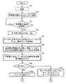
図6〜図8は、図1に示す電池モジュールMの動作の一例を示すフローチャートである。電池モジュールM1〜M3において、それぞれ略同時に並行して図6に示すステップS1〜S209の動作が実行される。 6 to 8 are flowcharts showing an example of the operation of the battery module M shown in FIG. In battery modules M1 to M3, operations in steps S1 to S209 shown in FIG.
まず、電池モジュールMが起動されると(ステップS1)、電池管理部32は、記憶部37に記憶されている消費電力値Wmを、通信部36によって主ECU2へ送信させる(ステップS2)。
First, when the battery module M is activated (step S1), the
次に、電池管理部32は、通信部36によって主ECU2から目標電力値Wtgが受信されるまで待機する(ステップS3でNO)。
Next, the
主ECU2では、通信部22によって、電池モジュールM1〜M3からそれぞれ消費電力値Wmが受信される。そして、システム制御部21によって、電池モジュールM1〜M3から受信された3つの消費電力値Wmのうち、最も大きな消費電力値が目標電力値Wtgとされる。システム制御部21は、目標電力値Wtgを、通信部22によって、電池モジュールM1〜M3へそれぞれ送信させる。
In the
そして、通信部36によって主ECU2から目標電力値Wtgが受信されると(ステップS3でYES)、電池管理部32は、ステップS4へ移行する。
When target power value Wtg is received from
ステップS4において、デューティ比算出部33は、目標電力値Wtgから消費電力値Wmを減算して得られた差を、差分電力値Wd(差分電力)として算出する(ステップS4)。
In step S4, the duty
次に、デューティ比算出部33は、スイッチング素子SW1をオンさせることによって、分圧電圧Vth1〜Vth6を生じさせる。また、デューティ比算出部33は、省電力回路35によってADコンバータ31をオン(動作)させる。そして、デューティ比算出部33は、ADコンバータ31によって分圧電圧Vth1〜Vth6をデジタル値に変換させることによって、温度T1〜T6を検出する(ステップS5)。
Next, the duty
次に、デューティ比算出部33は、記憶部37に記憶された温度電力情報Dt(図4)を参照し、温度T1〜T6に対応する消費電力値Wt(1)〜Wt(6)を取得する(ステップS6)。以下、温度T1に対応する消費電力値Wtを消費電力値Wt(1)、温度T2に対応する消費電力値Wtを消費電力値Wt(2)のように、温度Tの番号を消費電力値Wtに括弧で付して、温度と電源電流値との対応を示す。
Next, the duty
そして、デューティ比算出部33は、消費電力値Wt(1)〜Wt(6)の合計を総消費電力値Wtsとして算出する(ステップS7)。
Then, the duty
次に、デューティ比算出部33は、差分電力値Wdと総消費電力値Wtsとを比較する(ステップS8)。そして、差分電力値Wdが総消費電力値Wts以下であれば(ステップS8でYES)、デューティ比算出部33は、差分電力値Wdを総消費電力値Wtsで除算した商をデューティ比Drtとして算出し、デューティ比Drv及びデューティ比Dradを0として(ステップS9)、ステップS201へ移行する。
Next, the duty
デューティ比Drv及びデューティ比Dradを0にすることは、スイッチング素子SW2を常時オフさせ、ADコンバータ31を常時オフ(動作停止)させることを意味する。
Setting the duty ratio Drv and the duty ratio Drad to 0 means that the switching element SW2 is always turned off and the
ステップS9において設定されたデューティ比Drt,Drv,Dradは、このデューティ比Drt,Drv,Dradでスイッチング素子SW1,SW2,ADコンバータ31をそれぞれオンオフした場合に二次電池Bから電流消費回路である温度検出回路4、電圧検出回路5、及びADコンバータ31へ供給される電力の平均値を、差分電力値Wdと実質的に等しくさせるデューティ比となる。
The duty ratios Drt, Drv, Drad set in step S9 are the temperatures that are the current consumption circuit from the secondary battery B when the switching elements SW1, SW2,
一方、差分電力値Wdが総消費電力値Wtsを超えていれば(ステップS8でNO)、スイッチング素子SW1を常時オンしても、温度検出回路4で消費される電力は、差分電力値Wdに満たないことを意味する。そこで、デューティ比算出部33は、デューティ比Drtを1とし(ステップS10)、さらに電圧検出回路5で電力を消費させるべく、ステップS101へ移行する。
On the other hand, if the differential power value Wd exceeds the total power consumption value Wts (NO in step S8), even if the switching element SW1 is always turned on, the power consumed by the
デューティ比Drtを1にすることは、スイッチング素子SW1を常時オンすることを意味する。 Setting the duty ratio Drt to 1 means that the switching element SW1 is always turned on.
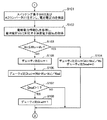
図7を参照して、ステップS101において、デューティ比算出部33は、スイッチング素子SW2をオンし、かつ省電力回路35によってADコンバータ31をオン(動作)させる。そして、デューティ比算出部33は、ADコンバータ31によって電圧Vb1をデジタル値に変換させることによって、電池電圧Vbを検出する(ステップS101)。デューティ比算出部33は、電池電圧Vbを検出すると、省電力回路35によってADコンバータ31をオフ(停止)させる。
Referring to FIG. 7, in step S <b> 101, duty
次に、デューティ比算出部33は、記憶部37に記憶された電検電力情報Dv(図5)を参照し、電池電圧Vbに対応する消費電力値Wvを取得する(ステップS102)。
Next, the duty
次に、デューティ比算出部33は、差分電力値Wdと、総消費電力値Wtsと消費電力値Wvとの加算値とを比較する(ステップS103)。そして、差分電力値Wdが、総消費電力値Wtsと消費電力値Wvとの加算値以下であれば(ステップS103でYES)、デューティ比算出部33は、差分電力値Wdから総消費電力値Wtsを減算した差を、消費電力値Wvで除算した商をデューティ比Drvとして算出し、デューティ比Dradを0として(ステップS104)、ステップS201へ移行する。
Next, the duty
ステップS10,S104において設定されたデューティ比Drt,Drv,Dradは、このデューティ比Drt,Drv,Dradでスイッチング素子SW1,SW2,ADコンバータ31をそれぞれオンオフした場合に二次電池Bから電流消費回路である温度検出回路4、電圧検出回路5、及びADコンバータ31へ供給される電力の平均値を、差分電力値Wdと実質的に等しくさせるデューティ比となる。
The duty ratios Drt, Drv, Drad set in steps S10, S104 are the current consumption circuits from the secondary battery B when the switching elements SW1, SW2,
一方、差分電力値Wdが、総消費電力値Wtsと消費電力値Wvとの加算値を超えていれば(ステップS103でNO)、スイッチング素子SW1及びスイッチング素子SW2を共に常時オンしても、温度検出回路4及び電圧検出回路5で消費される電力は、差分電力値Wdに満たないことを意味する。そこで、デューティ比算出部33は、デューティ比Drvを1とし(ステップS105)、さらにADコンバータ31で電力を消費させるべくステップS106へ移行する。
On the other hand, if the differential power value Wd exceeds the added value of the total power consumption value Wts and the power consumption value Wv (NO in step S103), the temperature can be maintained even if both the switching element SW1 and the switching element SW2 are always turned on. It means that the power consumed by the
デューティ比Drvを1とすることは、スイッチング素子SW2を常時オンすることを意味する。 Setting the duty ratio Drv to 1 means that the switching element SW2 is always turned on.
ステップS106において、デューティ比算出部33は、差分電力値Wdから総消費電力値Wts及び消費電力値Wvを減算した差を、消費電力値Wadで除算して得られた商をデューティ比Dradとして算出する(ステップS106)。
In step S106, the duty
ステップS10,S105,S106において設定されたデューティ比Drt,Drv,Dradは、このデューティ比Drt,Drv,Dradでスイッチング素子SW1,SW2,ADコンバータ31をそれぞれオンオフした場合に二次電池Bから電流消費回路である温度検出回路4、電圧検出回路5、及びADコンバータ31へ供給される電力の平均値を、差分電力値Wdと実質的に等しくさせるデューティ比となる。
The duty ratios Drt, Drv, Drad set in steps S10, S105, S106 are consumed by the secondary battery B when the switching elements SW1, SW2,
次に、デューティ比算出部33は、デューティ比Dradを1と比較する(ステップS107)。そして、デューティ比Dradが1以下であれば(ステップS107でNO)、デューティ比Drt,Drv,Dradに応じてスイッチング素子SW1,SW2、及びADコンバータ31を動作させるべく、ステップS201へ移行する。
Next, the duty
一方、デューティ比Dradが1を超えていれば(ステップS107でYES)、デューティ比Dradを、1を超える値にはできないから、デューティ比算出部33は、デューティ比Dradを1とし(ステップS108)、ステップS201へ移行する。
On the other hand, if the duty ratio Drad exceeds 1 (YES in step S107), the duty ratio Drad cannot be set to a value exceeding 1, so the duty
図8を参照して、ステップS201において、電源制御部34は、温度検出回路4によって温度検出処理を実行させるときは(ステップS201でYES)、スイッチング素子SW1をオンさせて、ステップS204へ移行する。
Referring to FIG. 8, in step S201, power
一方、温度検出回路4による温度検出処理を実行させないときは(ステップS201でNO)、電源制御部34は、スイッチング素子SW1を、デューティ比Drtでオンオフさせて(ステップS203)、ステップS204へ移行する。
On the other hand, when the temperature detection process by the
ステップS204において、電源制御部34は、電圧検出回路5によって電圧検出処理を実行させるときは(ステップS204でYES)、スイッチング素子SW2をオンさせて、ステップS207へ移行する。
In step S204, when the
一方、電圧検出回路5によって電圧検出処理を実行させないときは(ステップS204でNO)、電源制御部34は、スイッチング素子SW2を、デューティ比Drvでオンオフさせて(ステップS206)、ステップS207へ移行する。
On the other hand, when the voltage detection process is not executed by the voltage detection circuit 5 (NO in step S204), the power
ステップS207において、電源制御部34は、ADコンバータ31によってアナログデジタル変換処理を実行させるとき、例えば温度検出処理及び電圧検出処理のうち少なくとも一方が実行されるとき(ステップS207でYES)、電源制御部34は、省電力回路35によってADコンバータ31をオン(動作)させ(ステップS208)、以下、ステップS201〜S209を繰り返させる。
In step S207, the power
一方、ADコンバータ31によるアナログデジタル変換処理が実行されないとき、例えば温度検出処理及び電圧検出処理のいずれもが実行されないとき(ステップS207でNO)、電源制御部34は、省電力回路35によって、ADコンバータ31を、デューティ比Dradでオン(動作)オフ(停止)させ(ステップS209)、以下、ステップS201〜S209を繰り返させる。
On the other hand, when the analog-digital conversion process by the
より具体的に説明すると、例えば、電池モジュールM1において、消費電力値Wmが1.688W(ステップS2)、目標電力値Wtgが1.691W(ステップS3)、差分電力値Wdが3mW(ステップS4)、温度T1〜T6がすべて20℃(ステップS5)であった場合、消費電力値Wt(1)〜Wt(6)は、図4に示す温度電力情報Dtから、0.67mWとなり(ステップS6)、総消費電力値Wtsは4.02mWとなる(ステップS7)。 More specifically, for example, in the battery module M1, the power consumption value Wm is 1.688 W (step S2), the target power value Wtg is 1.661 W (step S3), and the differential power value Wd is 3 mW (step S4). When the temperatures T1 to T6 are all 20 ° C. (step S5), the power consumption values Wt (1) to Wt (6) are 0.67 mW from the temperature power information Dt shown in FIG. 4 (step S6). The total power consumption value Wts is 4.02 mW (step S7).
そうすると、Wd(3mW)≦Wts(4.02mW)であるから(ステップS8でYES)、デューティ比Drt=3/4.02=0.75、デューティ比Drv=0、デューティ比Drad=0となる(ステップS9)。 Then, since Wd (3 mW) ≦ Wts (4.02 mW) (YES in step S8), the duty ratio Drt = 3 / 4.02 = 0.75, the duty ratio Drv = 0, and the duty ratio Drad = 0. (Step S9).
以下、温度検出処理、電圧検出処理、及びアナログデジタル変換処理は実行されないものとすると、ステップS203において、スイッチング素子SW1がデューティ比Drt=0.75でオン、オフされる。具体的には、デューティ比は、オン時間/オンオフ周期であるから、所定の周期、例えば1秒のうち、0.75秒間スイッチング素子SW1がオンされ、0.25秒間、スイッチング素子SW1がオフされる。そうすると、温度検出回路4に流れる電流の1周期の平均値は、Wts×Drt=4.02mW×0.75=3.02mWとなる。
Hereinafter, assuming that the temperature detection process, the voltage detection process, and the analog-digital conversion process are not executed, in step S203, the switching element SW1 is turned on / off with the duty ratio Drt = 0.75. Specifically, since the duty ratio is an on-time / on-off cycle, the switching element SW1 is turned on for 0.75 seconds within a predetermined cycle, for example, 1 second, and the switching element SW1 is turned off for 0.25 seconds. The Then, the average value of one period of the current flowing through the
デューティ比Drv=0、デューティ比Drad=0であって、電圧検出回路5及びADコンバータ31に流れる電流は0であるから、温度検出回路4、電圧検出回路5、及びADコンバータ31の消費電力1周期の平均値が、差分電力値Wd=3mWと実質的に等しくされる。
Since the duty ratio Drv = 0, the duty ratio Drad = 0, and the current flowing through the
なお、温度検出回路4の消費電力1周期の平均値=3.02mWと、差分電力値Wd=3mWとの差は、計算上の丸め誤差により生じたものである。また、実際には、電源部6において電力損失も発生する。このように、温度検出回路4、電圧検出回路5、及びADコンバータ31の消費電力の平均値と、差分電力値Wdとの差が、計算誤差や、温度T1〜T6、電池電圧Vb等の検出誤差、あるいは電源部6の電力損失等により生じた誤差範囲内であれば、温度検出回路4、電圧検出回路5、及びADコンバータ31の消費電力の平均値と差分電力値Wdとは、実質的に等しい。このように、二次電池Bから電流消費回路へ供給される消費電力の平均値と、差分電力値Wdとの差異が、温度、電圧の検出誤差、電源回路の電力損失、及び計算誤差等により生じる差異の範囲内であれば、実質的に等しい。
Note that the difference between the average value of power consumption in one period of the
他の具体例では、例えば、電池モジュールM1において、消費電力値Wmが1.673W(ステップS2)、目標電力値Wtgが1.678W(ステップS3)、差分電力値Wdが5mW(ステップS4)、温度T1〜T6がすべて20℃(ステップS5)であった場合、消費電力値Wt(1)〜Wt(6)は、図4に示す温度電力情報Dtから、0.67mWとなり(ステップS6)、総消費電力値Wtsは4.02mWとなる(ステップS7)。 In another specific example, for example, in the battery module M1, the power consumption value Wm is 1.673 W (step S2), the target power value Wtg is 1.678 W (step S3), and the differential power value Wd is 5 mW (step S4). When the temperatures T1 to T6 are all 20 ° C. (step S5), the power consumption values Wt (1) to Wt (6) are 0.67 mW from the temperature power information Dt shown in FIG. 4 (step S6). The total power consumption value Wts is 4.02 mW (step S7).
そうすると、Wd(5mW)>Wts(4.02mW)であるから(ステップS8でNO)、デューティ比Drt=1(ステップS10)となる。 Then, since Wd (5 mW)> Wts (4.02 mW) (NO in step S8), the duty ratio Drt = 1 (step S10).
次に、電池電圧Vbが42.0V(ステップS101)であった場合、消費電力値Wvは、図5に示す電検電力情報Dvから、10.38mWとなる(ステップS102)。そうすると、Wd(5mW)≦Wts(4.02mW)+Wv(10.38mW)であるから(ステップS103でYES)、デューティ比Drv=(5−4.02)/10.38=0.09、デューティ比Drad=0となる(ステップS104)。 Next, when the battery voltage Vb is 42.0 V (step S101), the power consumption value Wv is 10.38 mW based on the electric inspection power information Dv shown in FIG. 5 (step S102). Then, since Wd (5 mW) ≦ Wts (4.02 mW) + Wv (10.38 mW) (YES in Step S103), duty ratio Drv = (5-4.02) /10.38=0.09, duty The ratio Drad = 0 (step S104).
以下、温度検出処理、電圧検出処理、及びアナログデジタル変換処理は実行されないものとすると、ステップS203において、スイッチング素子SW1がデューティ比Drt=1でオン、オフ(すなわち常時オン)され、ステップS206において、スイッチング素子SW2がデューティ比Drv=0.09でオン、オフされる。 Hereinafter, assuming that the temperature detection process, the voltage detection process, and the analog-digital conversion process are not executed, in step S203, the switching element SW1 is turned on and off (that is, always turned on) at the duty ratio Drt = 1, and in step S206. The switching element SW2 is turned on / off at a duty ratio Drv = 0.09.
そうすると、温度検出回路4及び電圧検出回路5の消費電力の平均値は、Wts+Wv×Drv=4.02mW+10.38mW×0.09=5.00mWとなる。デューティ比Drad=0であり、ADコンバータ31に流れる電流は0であるから、温度検出回路4、電圧検出回路5、及びADコンバータ31の消費電力の平均値が、差分電力値Wd=5mWと実質的に等しくされる。
Then, the average power consumption of the
さらに上記の例と電池電圧Vbが異なる他の具体例では、例えば、上記と同様、電池モジュールM1において、消費電力値Wmが1.673W(ステップS2)、目標電力値Wtgが1.683W(ステップS3)、差分電力値Wdが10mW(ステップS4)、温度T1〜T6がすべて20℃(ステップS5)、消費電力値Wt(1)〜Wt(6)が0.67mW(ステップS6)、総消費電力値Wtsは4.02mW(ステップS7)、デューティ比Drt=1(ステップS10)である場合において、電池電圧Vbが30.0V(ステップS101)、記憶部37に記憶されている消費電力値Wadが1.0mWであった場合、消費電力値Wvは、図5に示す電検電力情報Dvから、5.29mWとなる(ステップS102)。そうすると、Wd(10mW)>Wts(4.02mW)+Wv(5.29mW)であるから(ステップS103でNO)、デューティ比Drv=1(ステップS105)、デューティ比Drad=(10mW−4.02mW−5.29mW)/1.0mW=0.69となる(ステップS106)。
Further, in another specific example in which the battery voltage Vb is different from the above example, for example, in the battery module M1, the power consumption value Wm is 1.673 W (step S2) and the target power value Wtg is 1.683 W (step), as described above. S3), differential power value Wd is 10 mW (step S4), temperatures T1 to T6 are all 20 ° C. (step S5), power consumption values Wt (1) to Wt (6) are 0.67 mW (step S6), total consumption When the power value Wts is 4.02 mW (step S7) and the duty ratio Drt = 1 (step S10), the battery voltage Vb is 30.0 V (step S101), and the power consumption value Wad stored in the
以下、温度検出処理、電圧検出処理、及びアナログデジタル変換処理は実行されないものとすると、スイッチング素子SW1がデューティ比Drt=1でオン、オフ(常時オン)され(ステップS203)、スイッチング素子SW2がデューティ比Drv=1でオン、オフ(すなわち常時オン)され(ステップS206)、ADコンバータ31がデューティ比Dradでオン(動作)オフ(停止)される(ステップS209)。
Hereinafter, assuming that the temperature detection process, the voltage detection process, and the analog-digital conversion process are not executed, the switching element SW1 is turned on and off (always on) at the duty ratio Drt = 1 (step S203), and the switching element SW2 is duty cycle The ratio Drv = 1 is turned on and off (that is, always on) (step S206), and the
これにより、ADコンバータ31は、例えば1秒周期で0.52秒間オン(動作)し、0.48秒間オフ(停止)することを繰り返す。そうすると、温度検出回路4、電圧検出回路5、及びADコンバータ31の消費電力1周期の平均値は、Wts+Wv+Wad×Drad=4.02mW+5.29mW+1.0mW×0.69=10mWとなる。
As a result, the
すなわち、温度検出回路4、電圧検出回路5、及びADコンバータ31の消費電力の平均値が、差分電力値Wd=10mWと実質的に等しくされる。
That is, the average power consumption of the
そして、ステップS1〜S209の処理が、電池モジュールM1〜M3においてそれぞれ実行されることによって、電池モジュールM1〜M3で消費される消費電力、すなわち電池モジュールM1〜M3の二次電池Bが放電する放電電流が、すべて目標電力値Wtgと等しくなる。その結果、電池モジュールM1〜M3で消費される消費電流(消費電力)の差に起因する二次電池Bの蓄電電気量の不均衡が、生じるおそれを低減することができる。また、電池モジュール相互間の消費電流の差を吸収させる目的のためだけに放電回路を備える必要もない。 And the process of step S1-S209 is performed in battery module M1-M3, respectively, The power consumption consumed by battery module M1-M3, ie, the discharge which the secondary battery B of battery module M1-M3 discharges All currents are equal to the target power value Wtg. As a result, it is possible to reduce the possibility that an imbalance in the amount of electricity stored in the secondary battery B due to the difference in current consumption (power consumption) consumed by the battery modules M1 to M3 occurs. Further, it is not necessary to provide a discharge circuit only for the purpose of absorbing the difference in current consumption between the battery modules.
なお、ステップS2において、消費電力値Wmを主ECU2へ送信し、システム制御部21が各電池モジュールMの消費電力値Wmの最大値を目標電力値Wtgとして各電池モジュールMへ送信することで、ステップS3において各電池モジュールMで目標電力値Wtgが取得される例を示したが、電池モジュールMは、必ずしも各電池モジュールMの消費電力値Wmの最大値を目標電力値Wtgとして受信する例に限らない。
In step S2, the power consumption value Wm is transmitted to the
例えば、ステップS2,S3を実行せず、例えばスイッチング素子SW1,SW2及びADコンバータ31をオフさせたときの各電池モジュールM相互間の消費電力のばらつき範囲の最大値と想定される電力を、例えば実験的に求めてこれを目標電力値Wtgとし、この目標電力値Wtgを電池モジュールM1〜M3の記憶部37に予め記憶させておいてもよい。そして、デューティ比算出部33は、記憶部37に記憶された目標電力値Wtgを用いてもよい。このようにしても、電池モジュールM1〜M3で消費される電力が、すべて目標電力値Wtgと等しくなる。その結果、各電池モジュールM相互間の消費電力の差に起因する二次電池Bの蓄電電気量の不均衡が、生じるおそれを低減することができる。
For example, the power assumed to be the maximum value of the variation range of the power consumption between the battery modules M when the switching elements SW1 and SW2 and the
しかしながら、各電池モジュールMの消費電力のばらつき範囲の最大値と想定される消費電力を目標電力値Wtgとした場合には、電池モジュールM1〜M3の消費電力の最大値よりも、目標電力値Wtgの方が大きくなる場合がある。この場合、電池モジュールM1〜M3は、消費電力を目標電力値Wtgと略一致させるために、不必要な電流を流すことになる。そのため、電池モジュールM1〜M3の自己消費電力を増大させてしまうおそれがある。 However, when the power consumption assumed to be the maximum value of the variation range of the power consumption of each battery module M is the target power value Wtg, the target power value Wtg is larger than the maximum power consumption value of the battery modules M1 to M3. May be larger. In this case, the battery modules M1 to M3 pass an unnecessary current in order to make the power consumption substantially coincide with the target power value Wtg. Therefore, there is a risk of increasing the self-power consumption of the battery modules M1 to M3.
一方、ステップS2,S3を実行し、各電池モジュールMの消費電力値Wmの最大値を目標電力値Wtgとして用いる場合には、各電池モジュールMにおける消費電力を、各電池モジュールMの消費電力値Wmの最大値に一致させるように消費電力が増大する。その結果、元々消費電力値Wmが最大である電池モジュールMでは、電流消費回路によって電力を消費させる必要がなく、その他の電池モジュールMにおいても、電流消費回路によって消費させる電力を必要最小限にできる。その結果、ステップS2,S3を実行しない場合と比べて電池モジュールM1〜M3の消費電力を増大させてしまうおそれが低減される。 On the other hand, when steps S2 and S3 are executed and the maximum power consumption value Wm of each battery module M is used as the target power value Wtg, the power consumption of each battery module M is converted to the power consumption value of each battery module M. The power consumption increases so as to match the maximum value of Wm. As a result, in the battery module M originally having the maximum power consumption value Wm, it is not necessary to consume power by the current consumption circuit, and in other battery modules M, the power consumed by the current consumption circuit can be minimized. . As a result, the risk of increasing the power consumption of the battery modules M1 to M3 is reduced compared to the case where steps S2 and S3 are not executed.
また、ステップS5〜S108において、最初にデューティ比Drtを決定し、温度検出回路4だけでは差分電力値Wdを吸収できなかった場合にデューティ比Drvを0以外の値に決定し、さらに温度検出回路4と電圧検出回路5でも差分電力値Wdを吸収できなかった場合にデューティ比Dradを0以外の値に決定して温度検出回路4、電圧検出回路5、及びADコンバータ31で差分電力値Wdを吸収させる例を示したが、デューティ比Drt,Drv,Dradの決定順序、温度検出回路4、電圧検出回路5、及びADコンバータ31を用いる順序、温度検出回路4、電圧検出回路5、及びADコンバータ31を用いる組み合わせは、適宜決定すればよく、ステップS5〜S108で示した順序、組み合わせに限らない。
In steps S5 to S108, the duty ratio Drt is first determined. If the differential power value Wd cannot be absorbed by the
また、電流消費回路として、温度検出回路4、電圧検出回路5、及びADコンバータ31を用いる例を示したが、電流消費回路は、二次電池Bから供給された電力に基づく電源電流によって、二次電池Bを放電させる目的とは異なる目的の処理を行う回路であればよく、温度検出回路4、電圧検出回路5、及びADコンバータ31に限らない。
In addition, although an example in which the
また、電流消費回路として、必ずしも温度検出回路4、電圧検出回路5、及びADコンバータ31を備える必要はなく、温度検出回路4、電圧検出回路5、及びADコンバータ31のうち一つ、あるいは二つを電流消費回路として備えてもよい。
Further, the current detection circuit does not necessarily include the
また、電源部6で生じる電力損失を考慮して、電源部6から電力供給を受ける電流消費回路である温度検出回路4の消費電力値Wt、及びADコンバータ31の消費電力値Wadを補正してもよい。
In consideration of power loss generated in the
具体的には、例えば、電源部6の電力変換効率(電源部6から出力される電力/電源部6に入力される電力)がAであった場合、総消費電力値Wts、及び消費電力値Wadに基づき以下の式(1),(2)によって得られた消費電力値の補正値Wts’,Wad’を、ステップS8,S9,S103,S104,S106において総消費電力値Wts、及び消費電力値Wadの代わりに用いてもよい。
Specifically, for example, when the power conversion efficiency of the power supply unit 6 (power output from the
Wts’=Wts/A ・・・(1)
Wad’=Wad/A ・・・(2)
また、電源部6を備え、電源部6からの供給電力を消費する電流消費回路(温度検出回路4及びADコンバータ31)を含む例を示したが、電源部6からの供給電力を消費する回路を電流消費回路として用いず、電圧検出回路5のように、電池電圧Vbを電源電圧として用いる負荷回路のみを、電流消費回路として用いてもよい。この場合、電池モジュールMや電流消費回路の消費電流に電池電圧Vbを乗算した値がそれぞれ電池モジュールMや電流消費回路の消費電力となるから、消費電流値は、間接的に消費電力値を表す情報となる。この場合、消費電流値を、消費電力値を表す情報として用いることができる。同様に、電源部6に入力される電流値と、出力される電流値とが等しい場合も、消費電流値を、消費電力値を表す情報として用いることができる。
Wts ′ = Wts / A (1)
Wad '= Wad / A (2)
In addition, although an example including the current consumption circuit (the
このように、消費電流値を、消費電力値を表す情報として用いることができる場合、消費電力値Wmの代わりに電池モジュールMの消費電流値を消費電力情報として用い、目標電力値Wtg及び差分電力値Wdの代わりにWtg及びWdに対応する電流値を用い、消費電力値Wm,Wt,Wv,Wadの代わりに、それぞれに対応する消費電流値を用いてもよい。このように、ステップS1〜S108において、電力値の代わりに電流値を用いた場合であっても、ステップS201〜S209において、結果的に二次電池Bから電流消費回路へ供給される電力の平均値を、目標電力値Wtgと電池モジュールMの消費電力との差に相当する差分電力と実質的に等しくさせることになる。 Thus, when the current consumption value can be used as information representing the power consumption value, the current consumption value of the battery module M is used as the power consumption information instead of the power consumption value Wm, and the target power value Wtg and the differential power are used. Current values corresponding to Wtg and Wd may be used instead of the value Wd, and current consumption values corresponding to the respective power consumption values Wm, Wt, Wv, and Wad may be used. Thus, even if the current value is used instead of the power value in steps S1 to S108, the average of the power supplied as a result from the secondary battery B to the current consumption circuit in steps S201 to S209. The value is made substantially equal to the difference power corresponding to the difference between the target power value Wtg and the power consumption of the battery module M.
本発明に係る電池モジュール、及び電池管理システムは、携帯型パーソナルコンピュータ、デジタルカメラ、ビデオカメラ、及び携帯電話機等の電子機器、並びに、太陽電池や発電装置と二次電池とを組み合わされた電源システム及び無停電源装置等の電池搭載装置、並びにハイブリッドエレベータ等、電池を用いる種々の電池電源システムに適用することができる。特に電気自動車やハイブリッドカー等の車両に用いられる電池モジュール及び電池管理システムとして、好適に利用することができる。 A battery module and a battery management system according to the present invention include a portable personal computer, a digital camera, a video camera, a mobile phone, and other electronic devices, and a power supply system in which a solar battery, a power generation device, and a secondary battery are combined. The present invention can be applied to various battery power supply systems using batteries, such as battery mounted devices such as uninterruptible power supply devices, and hybrid elevators. In particular, it can be suitably used as a battery module and a battery management system used in vehicles such as electric cars and hybrid cars.
1 電池管理システム
2 主ECU
3 制御部
4 温度検出回路
5 電圧検出回路
6 電源部
21 システム制御部
22 通信部
31 ADコンバータ
32 電池管理部
33 デューティ比算出部
34 電源制御部
35 省電力回路
36 通信部
37 記憶部
41〜46 直列回路
A 電力変換効率
B 二次電池
Drt,Drv,Drad デューティ比
E 素電池
L 通信線
M,M1,M2,M3 電池モジュール
P1,P2 接続点
P(+) 正極端子
P(−) 負極端子
R1 抵抗
R4,R41〜R46 直列抵抗
R51,R52 分圧抵抗
SW1,SW2,SW3 スイッチング素子
T1〜T6 温度
Th,Th1〜Th6 サーミスタ
Vb 電池電圧
Vop 電源電圧
Vth1〜Vth6 分圧電圧
Wd 差分電力値
Wm,Wt,Wv,Wad 消費電力値
Wtg 目標電力値
Wts 総消費電力値
1
DESCRIPTION OF
Claims (10)
前記二次電池から供給された電力に基づく電源電流によって、前記二次電池を放電させる目的とは異なる目的の処理を行う電流消費回路と、
前記電流消費回路へ供給される電源電流をオンオフする電流開閉部と、
前記二次電池から供給された電力に基づき動作する制御部と、
前記電池モジュールの消費電力に関する消費電力情報を予め記憶する記憶部とを備え、
前記制御部は、
前記電流開閉部によって前記電源電流をオンオフさせることによって前記二次電池から前記電流消費回路へ供給される電力の平均値を、所定の目標電力と前記消費電力情報に基づく消費電力との差に相当する差分電力と実質的に等しくさせる前記オンオフのデューティ比を取得するデューティ比取得部と、
前記電流消費回路によって前記処理が実行される期間中、前記電流開閉部によって前記電源電流をオンさせ、前記電流消費回路によって前記処理が実行されないとき、前記電流開閉部によって前記電源電流を前記デューティ比でオンオフさせる電源制御部とを含む電池モジュール。 A battery module including a secondary battery,
A current consumption circuit that performs processing for a purpose different from the purpose of discharging the secondary battery by a power source current based on the power supplied from the secondary battery;
A current switching unit for turning on and off the power supply current supplied to the current consumption circuit;
A control unit that operates based on electric power supplied from the secondary battery;
A storage unit that stores power consumption information related to the power consumption of the battery module in advance;
The controller is
An average value of power supplied from the secondary battery to the current consumption circuit by turning on and off the power supply current by the current switching unit corresponds to a difference between predetermined target power and power consumption based on the power consumption information A duty ratio acquisition unit that acquires the on / off duty ratio to be substantially equal to the differential power to be
During the period in which the process is performed by the current consumption circuit, the power switch is turned on by the current switching unit, and when the process is not performed by the current consumption circuit, the current switching unit converts the power supply current to the duty ratio. A battery module including a power control unit that is turned on and off at a time.
前記二次電池の温度を検出するサーミスタと、
前記サーミスタに直列に接続され、かつ予め設定された抵抗値を有する直列抵抗とを含む温度検出回路を含み、
前記温度検出回路の処理は、
前記直列抵抗と前記サーミスタとの直列回路を前記電源電流が流れることにより前記直列抵抗と前記サーミスタとの接続点に生じる電圧を、前記二次電池の温度を示す温度情報として出力する温度検出処理である請求項1記載の電池モジュール。 The current consumption circuit is:
A thermistor for detecting the temperature of the secondary battery;
A temperature detection circuit including a series resistor connected in series to the thermistor and having a preset resistance value;
The processing of the temperature detection circuit is as follows:
A temperature detection process for outputting, as temperature information indicating the temperature of the secondary battery, a voltage generated at a connection point between the series resistor and the thermistor when the power supply current flows through a series circuit of the series resistor and the thermistor. The battery module according to claim 1.
前記温度検出回路によって前記処理が実行されることにより出力された前記温度情報と、前記目標電力と、前記消費電力情報とに基づいて、前記平均値が前記差分電力となるように、前記オンオフのデューティ比を求める請求項2記載の電池モジュール。 The duty ratio acquisition unit
Based on the temperature information output by the temperature detection circuit executing the processing, the target power, and the power consumption information, the on / off state is set so that the average value becomes the difference power. The battery module according to claim 2, wherein the duty ratio is obtained.
前記二次電池の端子電圧を分圧する第1及び第2分圧抵抗を含む電圧検出回路を含み、
前記電圧検出回路の処理は、
前記第1及び第2分圧抵抗の直列回路を前記電源電流が流れることにより前記第1及び第2分圧抵抗によって分圧された電圧を、前記二次電池の端子電圧を示す電池電圧情報として出力する電圧検出処理である請求項1〜3のいずれか1項に記載の電池モジュール。 The current consumption circuit is:
A voltage detection circuit including first and second voltage dividing resistors for dividing the terminal voltage of the secondary battery;
The processing of the voltage detection circuit is as follows:
The voltage divided by the first and second voltage dividing resistors as the power supply current flows through the series circuit of the first and second voltage dividing resistors is used as battery voltage information indicating the terminal voltage of the secondary battery. The battery module according to claim 1, which is a voltage detection process for outputting.
前記電圧検出回路によって前記処理が実行されることにより出力された前記電池電圧情報と、前記目標電力と、前記消費電力情報とに基づいて、前記平均値が前記差分電力となるように、前記オンオフのデューティ比を求める請求項4記載の電池モジュール。 The duty ratio acquisition unit
Based on the battery voltage information output by the voltage detection circuit executing the processing, the target power, and the power consumption information, the average value becomes the differential power, so that the on / off is performed. The battery module according to claim 4, wherein the duty ratio is calculated.
前記電流開閉部は、前記制御部からの指示に応じて前記電流消費回路へ供給される電源電流をオフする省電力回路を含む請求項1〜5のいずれか1項に記載の電池モジュール。 The control unit, at least a part of the current consumption circuit, and the current switching unit are integrated in a single integrated circuit,
The battery module according to claim 1, wherein the current switching unit includes a power saving circuit that turns off a power supply current supplied to the current consumption circuit in accordance with an instruction from the control unit.
前記電流開閉部は、前記制御部からの指示に応じて前記電流消費回路へ供給される電源電流をオフする省電力回路を含む請求項1記載の電池モジュール。 The control unit, the current consumption circuit, and the current switching unit are integrated in a single integrated circuit,
The battery module according to claim 1, wherein the current switching unit includes a power saving circuit that turns off a power supply current supplied to the current consumption circuit in accordance with an instruction from the control unit.
前記消費電力のばらつき範囲における上限値に相当する電力以上の値を、前記目標電力として予め記憶する請求項1〜7のいずれか1項に記載の電池モジュール。 The storage unit further includes:
The battery module according to any one of claims 1 to 7, wherein a value equal to or higher than an upper limit value in the power consumption variation range is stored in advance as the target power.
前記複数の電池モジュールにおける前記記憶部から前記消費電力情報をそれぞれ取得し、前記取得された各消費電力情報が示す前記消費電力のうち、最も大きな消費電力を前記目標電力として、その目標電力を示す情報を前記各電池モジュールの前記デューティ比取得部へ出力するシステム制御部を備える電池管理システム。 A plurality of the battery modules according to any one of claims 1 to 8,
The power consumption information is respectively acquired from the storage unit in the plurality of battery modules, and among the power consumptions indicated by the acquired power consumption information, the largest power consumption is set as the target power and the target power is indicated. A battery management system comprising a system control unit that outputs information to the duty ratio acquisition unit of each battery module.
Priority Applications (1)
| Application Number | Priority Date | Filing Date | Title |
|---|---|---|---|
| JP2012107909A JP2013236492A (en) | 2012-05-09 | 2012-05-09 | Battery module and battery management system |
Applications Claiming Priority (1)
| Application Number | Priority Date | Filing Date | Title |
|---|---|---|---|
| JP2012107909A JP2013236492A (en) | 2012-05-09 | 2012-05-09 | Battery module and battery management system |
Publications (1)
| Publication Number | Publication Date |
|---|---|
| JP2013236492A true JP2013236492A (en) | 2013-11-21 |
Family
ID=49762159
Family Applications (1)
| Application Number | Title | Priority Date | Filing Date |
|---|---|---|---|
| JP2012107909A Pending JP2013236492A (en) | 2012-05-09 | 2012-05-09 | Battery module and battery management system |
Country Status (1)
| Country | Link |
|---|---|
| JP (1) | JP2013236492A (en) |
Cited By (9)
| Publication number | Priority date | Publication date | Assignee | Title |
|---|---|---|---|---|
| WO2015186327A1 (en) * | 2014-06-06 | 2015-12-10 | パナソニックIpマネジメント株式会社 | Electricity storage device and power supply device |
| JP2016140170A (en) * | 2015-01-27 | 2016-08-04 | 株式会社デンソー | Discharge control device for battery block |
| CN108604711A (en) * | 2016-10-21 | 2018-09-28 | 株式会社Lg化学 | By means of the method and system of effective battery equilibrium of duty control |
| CN110071539A (en) * | 2019-03-26 | 2019-07-30 | 张锐明 | For improving the control device and control method of battery pack balancing |
| CN112780577A (en) * | 2019-11-05 | 2021-05-11 | 长城汽车股份有限公司 | Control method and system of battery loop water pump and vehicle |
| CN113612285A (en) * | 2021-08-13 | 2021-11-05 | 广州城市理工学院 | Automatic forward and reverse charging method |
| CN114006998A (en) * | 2021-10-29 | 2022-02-01 | 浙江舜宇智领技术有限公司 | Vehicle-mounted camera module temperature protection system and protection method thereof |
| CN114388938A (en) * | 2020-10-21 | 2022-04-22 | 航天科工惯性技术有限公司 | Energy storage battery temperature control system |
| WO2023068557A1 (en) * | 2021-10-19 | 2023-04-27 | 주식회사 엘지에너지솔루션 | Current consumption control device and battery management device comprising same |
-
2012
- 2012-05-09 JP JP2012107909A patent/JP2013236492A/en active Pending
Cited By (14)
| Publication number | Priority date | Publication date | Assignee | Title |
|---|---|---|---|---|
| WO2015186327A1 (en) * | 2014-06-06 | 2015-12-10 | パナソニックIpマネジメント株式会社 | Electricity storage device and power supply device |
| JP2016140170A (en) * | 2015-01-27 | 2016-08-04 | 株式会社デンソー | Discharge control device for battery block |
| CN108604711B (en) * | 2016-10-21 | 2021-06-29 | 株式会社Lg化学 | Method and system for efficient cell balancing via duty control |
| CN108604711A (en) * | 2016-10-21 | 2018-09-28 | 株式会社Lg化学 | By means of the method and system of effective battery equilibrium of duty control |
| US10840711B2 (en) | 2016-10-21 | 2020-11-17 | Lg Chem, Ltd. | Method and system for effective battery cell balancing through duty control |
| CN110071539A (en) * | 2019-03-26 | 2019-07-30 | 张锐明 | For improving the control device and control method of battery pack balancing |
| CN110071539B (en) * | 2019-03-26 | 2023-02-03 | 张锐明 | Control device and control method for improving battery pack balance |
| CN112780577A (en) * | 2019-11-05 | 2021-05-11 | 长城汽车股份有限公司 | Control method and system of battery loop water pump and vehicle |
| CN114388938A (en) * | 2020-10-21 | 2022-04-22 | 航天科工惯性技术有限公司 | Energy storage battery temperature control system |
| CN114388938B (en) * | 2020-10-21 | 2023-10-17 | 航天科工惯性技术有限公司 | Energy storage battery temperature control system |
| CN113612285A (en) * | 2021-08-13 | 2021-11-05 | 广州城市理工学院 | Automatic forward and reverse charging method |
| WO2023068557A1 (en) * | 2021-10-19 | 2023-04-27 | 주식회사 엘지에너지솔루션 | Current consumption control device and battery management device comprising same |
| CN114006998A (en) * | 2021-10-29 | 2022-02-01 | 浙江舜宇智领技术有限公司 | Vehicle-mounted camera module temperature protection system and protection method thereof |
| CN114006998B (en) * | 2021-10-29 | 2023-08-04 | 浙江舜宇智领技术有限公司 | Temperature protection system and protection method for vehicle-mounted camera module |
Similar Documents
| Publication | Publication Date | Title |
|---|---|---|
| JP2013236492A (en) | Battery module and battery management system | |
| JP4768090B2 (en) | Charge control circuit, battery pack, and charging system | |
| JP5179047B2 (en) | Storage device abnormality detection device, storage device abnormality detection method, and abnormality detection program thereof | |
| CN105518924B (en) | Battery apparatus and electric vehicle | |
| JP5248764B2 (en) | Storage element abnormality detection device, storage element abnormality detection method, and abnormality detection program thereof | |
| US10044211B2 (en) | Battery pack and method of controlling the same | |
| JP5208149B2 (en) | Protection circuit and battery pack | |
| CN103329338B (en) | Battery pack and power consumption apparatus | |
| TWI672889B (en) | Control device, power storage device, power storage system, and recording medium | |
| US8643500B2 (en) | Apparatus and method for diagnosing abnormality in cell balancing circuit | |
| JP4486046B2 (en) | Battery pack monitoring apparatus and method | |
| US9214702B2 (en) | Batteries for electric tools | |
| JP4237804B2 (en) | Battery pack protection device and battery pack device | |
| US20110285538A1 (en) | Apparatus and method for diagnosing abnormality in cell balancing circuit | |
| US10873201B2 (en) | Battery management apparatus and method for protecting a lithium iron phosphate cell from over-voltage using the same | |
| KR102500362B1 (en) | Apparatus for managing battery | |
| CN101611525A (en) | Charging system, charging device and battery component | |
| JP2010124640A5 (en) | ||
| JP2022089830A (en) | Monitoring system for series-connected battery cells | |
| JP2012052857A (en) | Abnormality detection circuit for secondary battery and battery power supply device | |
| JP2011182550A (en) | Battery voltage monitoring device | |
| KR20200107614A (en) | Electronic device for determining State of Charge of battery device, and operating method of the electronic device | |
| JP2011053097A (en) | Discharge management circuit and battery pack | |
| CN103633682B (en) | Battery pack and its control method | |
| US9455580B2 (en) | Battery management system and method |