KR102437941B1 - Battery holder, battery exchange device, electric vehicle and installation method for electric vehicle - Google Patents
Battery holder, battery exchange device, electric vehicle and installation method for electric vehicle Download PDFInfo
- Publication number
- KR102437941B1 KR102437941B1 KR1020227003183A KR20227003183A KR102437941B1 KR 102437941 B1 KR102437941 B1 KR 102437941B1 KR 1020227003183 A KR1020227003183 A KR 1020227003183A KR 20227003183 A KR20227003183 A KR 20227003183A KR 102437941 B1 KR102437941 B1 KR 102437941B1
- Authority
- KR
- South Korea
- Prior art keywords
- support
- locking
- battery pack
- shaft
- battery
- Prior art date
Links
Images


Classifications
-
- H—ELECTRICITY
- H02—GENERATION; CONVERSION OR DISTRIBUTION OF ELECTRIC POWER
- H02J—CIRCUIT ARRANGEMENTS OR SYSTEMS FOR SUPPLYING OR DISTRIBUTING ELECTRIC POWER; SYSTEMS FOR STORING ELECTRIC ENERGY
- H02J7/00—Circuit arrangements for charging or depolarising batteries or for supplying loads from batteries
- H02J7/0042—Circuit arrangements for charging or depolarising batteries or for supplying loads from batteries characterised by the mechanical construction
- H02J7/0045—Circuit arrangements for charging or depolarising batteries or for supplying loads from batteries characterised by the mechanical construction concerning the insertion or the connection of the batteries
-
- H—ELECTRICITY
- H01—ELECTRIC ELEMENTS
- H01M—PROCESSES OR MEANS, e.g. BATTERIES, FOR THE DIRECT CONVERSION OF CHEMICAL ENERGY INTO ELECTRICAL ENERGY
- H01M50/00—Constructional details or processes of manufacture of the non-active parts of electrochemical cells other than fuel cells, e.g. hybrid cells
- H01M50/20—Mountings; Secondary casings or frames; Racks, modules or packs; Suspension devices; Shock absorbers; Transport or carrying devices; Holders
-
- B—PERFORMING OPERATIONS; TRANSPORTING
- B60—VEHICLES IN GENERAL
- B60K—ARRANGEMENT OR MOUNTING OF PROPULSION UNITS OR OF TRANSMISSIONS IN VEHICLES; ARRANGEMENT OR MOUNTING OF PLURAL DIVERSE PRIME-MOVERS IN VEHICLES; AUXILIARY DRIVES FOR VEHICLES; INSTRUMENTATION OR DASHBOARDS FOR VEHICLES; ARRANGEMENTS IN CONNECTION WITH COOLING, AIR INTAKE, GAS EXHAUST OR FUEL SUPPLY OF PROPULSION UNITS IN VEHICLES
- B60K1/00—Arrangement or mounting of electrical propulsion units
- B60K1/04—Arrangement or mounting of electrical propulsion units of the electric storage means for propulsion
-
- B—PERFORMING OPERATIONS; TRANSPORTING
- B60—VEHICLES IN GENERAL
- B60L—PROPULSION OF ELECTRICALLY-PROPELLED VEHICLES; SUPPLYING ELECTRIC POWER FOR AUXILIARY EQUIPMENT OF ELECTRICALLY-PROPELLED VEHICLES; ELECTRODYNAMIC BRAKE SYSTEMS FOR VEHICLES IN GENERAL; MAGNETIC SUSPENSION OR LEVITATION FOR VEHICLES; MONITORING OPERATING VARIABLES OF ELECTRICALLY-PROPELLED VEHICLES; ELECTRIC SAFETY DEVICES FOR ELECTRICALLY-PROPELLED VEHICLES
- B60L50/00—Electric propulsion with power supplied within the vehicle
- B60L50/50—Electric propulsion with power supplied within the vehicle using propulsion power supplied by batteries or fuel cells
- B60L50/60—Electric propulsion with power supplied within the vehicle using propulsion power supplied by batteries or fuel cells using power supplied by batteries
- B60L50/64—Constructional details of batteries specially adapted for electric vehicles
-
- B—PERFORMING OPERATIONS; TRANSPORTING
- B60—VEHICLES IN GENERAL
- B60L—PROPULSION OF ELECTRICALLY-PROPELLED VEHICLES; SUPPLYING ELECTRIC POWER FOR AUXILIARY EQUIPMENT OF ELECTRICALLY-PROPELLED VEHICLES; ELECTRODYNAMIC BRAKE SYSTEMS FOR VEHICLES IN GENERAL; MAGNETIC SUSPENSION OR LEVITATION FOR VEHICLES; MONITORING OPERATING VARIABLES OF ELECTRICALLY-PROPELLED VEHICLES; ELECTRIC SAFETY DEVICES FOR ELECTRICALLY-PROPELLED VEHICLES
- B60L53/00—Methods of charging batteries, specially adapted for electric vehicles; Charging stations or on-board charging equipment therefor; Exchange of energy storage elements in electric vehicles
- B60L53/80—Exchanging energy storage elements, e.g. removable batteries
-
- H—ELECTRICITY
- H01—ELECTRIC ELEMENTS
- H01M—PROCESSES OR MEANS, e.g. BATTERIES, FOR THE DIRECT CONVERSION OF CHEMICAL ENERGY INTO ELECTRICAL ENERGY
- H01M10/00—Secondary cells; Manufacture thereof
- H01M10/42—Methods or arrangements for servicing or maintenance of secondary cells or secondary half-cells
- H01M10/46—Accumulators structurally combined with charging apparatus
-
- H—ELECTRICITY
- H01—ELECTRIC ELEMENTS
- H01M—PROCESSES OR MEANS, e.g. BATTERIES, FOR THE DIRECT CONVERSION OF CHEMICAL ENERGY INTO ELECTRICAL ENERGY
- H01M50/00—Constructional details or processes of manufacture of the non-active parts of electrochemical cells other than fuel cells, e.g. hybrid cells
- H01M50/20—Mountings; Secondary casings or frames; Racks, modules or packs; Suspension devices; Shock absorbers; Transport or carrying devices; Holders
- H01M50/204—Racks, modules or packs for multiple batteries or multiple cells
- H01M50/207—Racks, modules or packs for multiple batteries or multiple cells characterised by their shape
-
- H—ELECTRICITY
- H01—ELECTRIC ELEMENTS
- H01M—PROCESSES OR MEANS, e.g. BATTERIES, FOR THE DIRECT CONVERSION OF CHEMICAL ENERGY INTO ELECTRICAL ENERGY
- H01M50/00—Constructional details or processes of manufacture of the non-active parts of electrochemical cells other than fuel cells, e.g. hybrid cells
- H01M50/20—Mountings; Secondary casings or frames; Racks, modules or packs; Suspension devices; Shock absorbers; Transport or carrying devices; Holders
- H01M50/244—Secondary casings; Racks; Suspension devices; Carrying devices; Holders characterised by their mounting method
-
- H—ELECTRICITY
- H01—ELECTRIC ELEMENTS
- H01M—PROCESSES OR MEANS, e.g. BATTERIES, FOR THE DIRECT CONVERSION OF CHEMICAL ENERGY INTO ELECTRICAL ENERGY
- H01M50/00—Constructional details or processes of manufacture of the non-active parts of electrochemical cells other than fuel cells, e.g. hybrid cells
- H01M50/20—Mountings; Secondary casings or frames; Racks, modules or packs; Suspension devices; Shock absorbers; Transport or carrying devices; Holders
- H01M50/249—Mountings; Secondary casings or frames; Racks, modules or packs; Suspension devices; Shock absorbers; Transport or carrying devices; Holders specially adapted for aircraft or vehicles, e.g. cars or trains
-
- H—ELECTRICITY
- H01—ELECTRIC ELEMENTS
- H01M—PROCESSES OR MEANS, e.g. BATTERIES, FOR THE DIRECT CONVERSION OF CHEMICAL ENERGY INTO ELECTRICAL ENERGY
- H01M50/00—Constructional details or processes of manufacture of the non-active parts of electrochemical cells other than fuel cells, e.g. hybrid cells
- H01M50/20—Mountings; Secondary casings or frames; Racks, modules or packs; Suspension devices; Shock absorbers; Transport or carrying devices; Holders
- H01M50/262—Mountings; Secondary casings or frames; Racks, modules or packs; Suspension devices; Shock absorbers; Transport or carrying devices; Holders with fastening means, e.g. locks
- H01M50/264—Mountings; Secondary casings or frames; Racks, modules or packs; Suspension devices; Shock absorbers; Transport or carrying devices; Holders with fastening means, e.g. locks for cells or batteries, e.g. straps, tie rods or peripheral frames
-
- H—ELECTRICITY
- H01—ELECTRIC ELEMENTS
- H01M—PROCESSES OR MEANS, e.g. BATTERIES, FOR THE DIRECT CONVERSION OF CHEMICAL ENERGY INTO ELECTRICAL ENERGY
- H01M50/00—Constructional details or processes of manufacture of the non-active parts of electrochemical cells other than fuel cells, e.g. hybrid cells
- H01M50/20—Mountings; Secondary casings or frames; Racks, modules or packs; Suspension devices; Shock absorbers; Transport or carrying devices; Holders
- H01M50/271—Lids or covers for the racks or secondary casings
-
- H—ELECTRICITY
- H01—ELECTRIC ELEMENTS
- H01M—PROCESSES OR MEANS, e.g. BATTERIES, FOR THE DIRECT CONVERSION OF CHEMICAL ENERGY INTO ELECTRICAL ENERGY
- H01M50/00—Constructional details or processes of manufacture of the non-active parts of electrochemical cells other than fuel cells, e.g. hybrid cells
- H01M50/20—Mountings; Secondary casings or frames; Racks, modules or packs; Suspension devices; Shock absorbers; Transport or carrying devices; Holders
- H01M50/296—Mountings; Secondary casings or frames; Racks, modules or packs; Suspension devices; Shock absorbers; Transport or carrying devices; Holders characterised by terminals of battery packs
-
- H—ELECTRICITY
- H01—ELECTRIC ELEMENTS
- H01M—PROCESSES OR MEANS, e.g. BATTERIES, FOR THE DIRECT CONVERSION OF CHEMICAL ENERGY INTO ELECTRICAL ENERGY
- H01M50/00—Constructional details or processes of manufacture of the non-active parts of electrochemical cells other than fuel cells, e.g. hybrid cells
- H01M50/20—Mountings; Secondary casings or frames; Racks, modules or packs; Suspension devices; Shock absorbers; Transport or carrying devices; Holders
- H01M50/298—Mountings; Secondary casings or frames; Racks, modules or packs; Suspension devices; Shock absorbers; Transport or carrying devices; Holders characterised by the wiring of battery packs
-
- H—ELECTRICITY
- H01—ELECTRIC ELEMENTS
- H01M—PROCESSES OR MEANS, e.g. BATTERIES, FOR THE DIRECT CONVERSION OF CHEMICAL ENERGY INTO ELECTRICAL ENERGY
- H01M50/00—Constructional details or processes of manufacture of the non-active parts of electrochemical cells other than fuel cells, e.g. hybrid cells
- H01M50/50—Current conducting connections for cells or batteries
- H01M50/569—Constructional details of current conducting connections for detecting conditions inside cells or batteries, e.g. details of voltage sensing terminals
-
- B—PERFORMING OPERATIONS; TRANSPORTING
- B60—VEHICLES IN GENERAL
- B60Y—INDEXING SCHEME RELATING TO ASPECTS CROSS-CUTTING VEHICLE TECHNOLOGY
- B60Y2200/00—Type of vehicle
- B60Y2200/90—Vehicles comprising electric prime movers
- B60Y2200/91—Electric vehicles
-
- H—ELECTRICITY
- H01—ELECTRIC ELEMENTS
- H01M—PROCESSES OR MEANS, e.g. BATTERIES, FOR THE DIRECT CONVERSION OF CHEMICAL ENERGY INTO ELECTRICAL ENERGY
- H01M2220/00—Batteries for particular applications
- H01M2220/20—Batteries in motive systems, e.g. vehicle, ship, plane
-
- H—ELECTRICITY
- H01—ELECTRIC ELEMENTS
- H01R—ELECTRICALLY-CONDUCTIVE CONNECTIONS; STRUCTURAL ASSOCIATIONS OF A PLURALITY OF MUTUALLY-INSULATED ELECTRICAL CONNECTING ELEMENTS; COUPLING DEVICES; CURRENT COLLECTORS
- H01R13/00—Details of coupling devices of the kinds covered by groups H01R12/70 or H01R24/00 - H01R33/00
- H01R13/62—Means for facilitating engagement or disengagement of coupling parts or for holding them in engagement
- H01R13/639—Additional means for holding or locking coupling parts together, after engagement, e.g. separate keylock, retainer strap
-
- Y—GENERAL TAGGING OF NEW TECHNOLOGICAL DEVELOPMENTS; GENERAL TAGGING OF CROSS-SECTIONAL TECHNOLOGIES SPANNING OVER SEVERAL SECTIONS OF THE IPC; TECHNICAL SUBJECTS COVERED BY FORMER USPC CROSS-REFERENCE ART COLLECTIONS [XRACs] AND DIGESTS
- Y02—TECHNOLOGIES OR APPLICATIONS FOR MITIGATION OR ADAPTATION AGAINST CLIMATE CHANGE
- Y02E—REDUCTION OF GREENHOUSE GAS [GHG] EMISSIONS, RELATED TO ENERGY GENERATION, TRANSMISSION OR DISTRIBUTION
- Y02E60/00—Enabling technologies; Technologies with a potential or indirect contribution to GHG emissions mitigation
- Y02E60/10—Energy storage using batteries
-
- Y—GENERAL TAGGING OF NEW TECHNOLOGICAL DEVELOPMENTS; GENERAL TAGGING OF CROSS-SECTIONAL TECHNOLOGIES SPANNING OVER SEVERAL SECTIONS OF THE IPC; TECHNICAL SUBJECTS COVERED BY FORMER USPC CROSS-REFERENCE ART COLLECTIONS [XRACs] AND DIGESTS
- Y02—TECHNOLOGIES OR APPLICATIONS FOR MITIGATION OR ADAPTATION AGAINST CLIMATE CHANGE
- Y02T—CLIMATE CHANGE MITIGATION TECHNOLOGIES RELATED TO TRANSPORTATION
- Y02T10/00—Road transport of goods or passengers
- Y02T10/60—Other road transportation technologies with climate change mitigation effect
- Y02T10/70—Energy storage systems for electromobility, e.g. batteries
-
- Y—GENERAL TAGGING OF NEW TECHNOLOGICAL DEVELOPMENTS; GENERAL TAGGING OF CROSS-SECTIONAL TECHNOLOGIES SPANNING OVER SEVERAL SECTIONS OF THE IPC; TECHNICAL SUBJECTS COVERED BY FORMER USPC CROSS-REFERENCE ART COLLECTIONS [XRACs] AND DIGESTS
- Y02—TECHNOLOGIES OR APPLICATIONS FOR MITIGATION OR ADAPTATION AGAINST CLIMATE CHANGE
- Y02T—CLIMATE CHANGE MITIGATION TECHNOLOGIES RELATED TO TRANSPORTATION
- Y02T10/00—Road transport of goods or passengers
- Y02T10/60—Other road transportation technologies with climate change mitigation effect
- Y02T10/7072—Electromobility specific charging systems or methods for batteries, ultracapacitors, supercapacitors or double-layer capacitors
Landscapes
- Chemical & Material Sciences (AREA)
- Chemical Kinetics & Catalysis (AREA)
- Electrochemistry (AREA)
- General Chemical & Material Sciences (AREA)
- Engineering & Computer Science (AREA)
- Mechanical Engineering (AREA)
- Transportation (AREA)
- Power Engineering (AREA)
- Aviation & Aerospace Engineering (AREA)
- Sustainable Energy (AREA)
- Sustainable Development (AREA)
- Life Sciences & Earth Sciences (AREA)
- Combustion & Propulsion (AREA)
- Manufacturing & Machinery (AREA)
- Battery Mounting, Suspending (AREA)
- Arrangement Or Mounting Of Propulsion Units For Vehicles (AREA)
- Electric Propulsion And Braking For Vehicles (AREA)
Abstract
본 발명은, 배터리 홀더, 배터리 교체 장치, 전기 자동차, 및 전기 자동차의 설치 방법을 공개하였다. 배터리 홀더는 전기 자동차의 차체에 설치되어 배터리 팩을 고정시키는데 사용되고, 배터리 홀더는 고정 브래킷, 잠금 메커니즘 및 다수의 지지 장치를 포함하며, 잠금 메커니즘은 고정 브래킷에 고정 설치되고, 지지 장치는 고정 브래킷의 배터리 팩을 향한 일 측에 고정 설치되고, 다수의 지지 장치는 배터리 팩을 지지하는 다수의 지지 포인트를 제공하는데 사용된다. 전기 자동차는 상기 배터리 홀더를 포함한다. 본 발명의 배터리 홀더와 이를 포함하는 전기 자동차는, 배터리 팩의 중량을 동시에 다수의 지지 장치와 잠금 메커니즘상에 분포할 수 있어, 고정 브래킷은 보다 균일하게 힘을 받고, 배터리 팩이 잠금 메커니즘에 가하는 작용력을 줄이고, 고정 브래킷상의 잠금 메커니즘에 힘이 집중되는 상황을 방지하고, 잠금 메커니즘의 내구한도를 향상시키고, 나아가 안전 성능을 향상시키며, 뿐만 아니라 배터리 팩 어셈블리와 배터리 홀더사이의 연결 강도도 향상시킨다. The present invention discloses a battery holder, a battery replacement device, an electric vehicle, and a method for installing an electric vehicle. The battery holder is installed on the body of the electric vehicle and used to fix the battery pack, the battery holder includes a fixing bracket, a locking mechanism and a plurality of supporting devices, the locking mechanism is fixedly installed on the fixing bracket, and the supporting device is the fixing bracket of the fixing bracket. It is fixedly installed on one side facing the battery pack, and a plurality of support devices are used to provide a plurality of support points for supporting the battery pack. The electric vehicle includes the battery holder. The battery holder of the present invention and the electric vehicle including the same can distribute the weight of the battery pack on a plurality of supporting devices and the locking mechanism at the same time, so that the fixing bracket receives the force more uniformly, and the battery pack applies the force to the locking mechanism. It reduces the working force, avoids the situation where the force is concentrated on the locking mechanism on the fixing bracket, improves the durability of the locking mechanism, and further improves the safety performance, but also improves the strength of the connection between the battery pack assembly and the battery holder. .

Description
본원 발명은 출원일자가 2017년 12월 29일인 중국 특허 출원 CN201711482966.3과 CN201711486896.9의 우선권을 주장하는 바, 상기 중국 특허 출원의 모든 내용은 참조로서 본원 발명에 인용된다.The present invention claims priority to Chinese patent applications CN201711482966.3 and CN201711486896.9, filed on December 29, 2017, all of which are incorporated herein by reference.
본 발명은 전기 자동차 기술 분야에 관한 것이며, 특별히 배터리 홀더, 배터리 교체 장치, 전기 자동차, 및 전기 자동차의 설치 방법에 관한 것이다.The present invention relates to the field of electric vehicle technology, and more particularly to a battery holder, a battery replacement device, an electric vehicle, and a method for installing an electric vehicle.
기존의 전기 자동차의 배터리 팩 설치 방식은 일반적으로 고정 방식과 교체가능 방식으로 나뉘고, 그중 고정 방식의 배터리 팩은 일반적으로 자동차에 고정하고, 충전시 직접 자동차를 충전 대상으로 한다. 하지만 교체가능 방식의 배터리 팩은, 일반적으로 능동적인 설치 방식을 채택하며, 배터리 팩을 수시로 분해하고 새로운 배터리 팩으로 교체 할 수 있다.The conventional battery pack installation method of an electric vehicle is generally divided into a fixed method and a replaceable method. Among them, the fixed type battery pack is generally fixed to the vehicle, and the vehicle is directly charged when charging. However, a replaceable battery pack generally adopts an active installation method, and the battery pack can be disassembled and replaced with a new battery pack from time to time.
새로운 배터리 팩으로 교체 하는 과정에서, 배터리 팩의 잠금 및 잠금 해제가 관련된다. 일반적으로, 배터리 팩의 좌우 양측면에 잠금 샤프트가 설치되어 있고; 잠금 메커니즘은 배터리 팩 홀더에 고정되어 배터리 교체 장치로 조립되며, 배터리 교체 장치는 다시 전기 자동차의 섀시에 설치되며; 잠금 샤프트는 잠금 메커니즘과 협동하여 배터리 팩의 잠금을 실현한다.In the process of replacing a new battery pack, locking and unlocking of the battery pack is involved. In general, lock shafts are installed on both left and right sides of the battery pack; The locking mechanism is fixed to the battery pack holder and assembled into a battery replacement device, which is installed in the chassis of the electric vehicle again; The locking shaft cooperates with the locking mechanism to realize locking of the battery pack.
그러나, 상기 구조 형태를 사용할 시 아래와 같은 결함이 존재 한다. 고정 브래킷에는 배터리 팩의 잠금 샤프트와 협동하는 잠금 메커니즘만 설치되어 있고, 배터리 팩의 중량이 고정 브래킷의 잠금 메커니즘에 집중되어, 잠금 메커니즘이 집중적으로 힘을 받으면서 사용 수명이 짧아지고, 배터리 팩과 고정 브래킷의 연결 강도가 낮아진다.However, the following defects exist when using the above structural form. The fixing bracket is equipped with only a locking mechanism that cooperates with the locking shaft of the battery pack, and the weight of the battery pack is concentrated on the locking mechanism of the fixing bracket, so that the locking mechanism receives intensive force, shortening the service life, and locking with the battery pack The connection strength of the bracket is lowered.
새로운 배터리 팩으로 교체 하는 과정에서, 전기 연결 장치도 관련되는데, 잠금 메커니즘은 배터리 팩과 배터리 팩 홀더사이의 연결에 영향 줄 뿐만 아니라, 배터리 팩과 전기 연결 장치사이의 전기적 연결의 안정성에도 영향을 준다.In the process of replacing with a new battery pack, the electrical connection is also involved. The locking mechanism not only affects the connection between the battery pack and the battery pack holder, but also affects the stability of the electrical connection between the battery pack and the electrical connection. .
하지만, 종래의 기술에서는, 잠금 메커니즘과 전기 연결 장치는 독립적으로 설치되기에, 잠금 메커니즘이 배터리 팩을 제자리로 잠궜지만 배터리 팩과 전기 연결 장치사이의 전기적 연결의 안정을 실현할수 없거나, 또는 배터리 팩과 전기 연결 장치사이는 비교적 안정적으로 전기 연결되었으나 배터리 팩이 제자리로 잠궈지지 못하는 상황이 쉽게 발생된다. 즉, 기존의 배터리 교체 장치는 잠금 메커니즘과 전기 연결 장치의 동기화를 실현하기 어렵고, 배터리 교체 효율 및 배터리 교체 안정성에 쉽게 영향을 준다. However, in the prior art, since the locking mechanism and the electrical connection device are installed independently, the locking mechanism locks the battery pack in place, but cannot realize the stability of the electrical connection between the battery pack and the electrical connection device, or the battery pack Although the electrical connection between the battery and the electrical connection device is relatively stable, a situation in which the battery pack cannot be locked in place easily occurs. That is, the conventional battery replacement device is difficult to realize the synchronization of the locking mechanism and the electrical connection device, and easily affects the battery replacement efficiency and battery replacement stability.
본 발명이 해결하고자 하는 기술적 과제는 선행기술에서의결함을 극복하기 위하여, 배터리 교체 장치 및 이의 설치 방법을 제공하는 것이다.The technical problem to be solved by the present invention is to provide a battery replacement device and a method for installing the same in order to overcome the deficiencies in the prior art.
본 발명은 하기와 같은 기술적 해결수단을 통해 상기 기술적 과제를 해결한다.The present invention solves the above technical problem through the following technical solutions.
배터리 홀더는,battery holder,
전기 자동차의 차체에 설치되어 배터리 팩을 고정시키는데 사용되고, 고정 브래킷 및 잠금 메커니즘을 포함하며, 상기 잠금 메커니즘은 상기 고정 브래킷에 고정 설치되고,It is installed on the vehicle body of the electric vehicle and used to fix the battery pack, comprising a fixing bracket and a locking mechanism, wherein the locking mechanism is fixedly installed on the fixing bracket,
다수의 지지 장치를 더 포함하고, 상기 지지 장치는 상기 고정 브래킷의 배터리 팩을 향한 일 측에 고정 설치되고, 다수의 상기 지지 장치는 상기 배터리 팩을 지지하는 다수의 지지 포인트를 제공하는데 사용된다.It further includes a plurality of support devices, the support devices are fixedly installed on one side of the fixing bracket toward the battery pack, and the plurality of support devices are used to provide a plurality of support points for supporting the battery pack.
본 해결수단에서, 잠금 메커니즘과 잠금 샤프트를 협동시켜 배터리 팩의 잠금을 실현하는 기초상에서, 배터리 팩에 다수의 지지부를 설치하고, 고정 브래킷 상에 상기 지지부를 지지하기 위한 다수의 지지 장치를 설치하여, 배터리 팩의 중량이 동시에 다수의 지지 장치와 잠금 메커니즘상에 분포되게 하여, 고정 브래킷이 보다 균일하게 힘을 받고, 배터리 팩이 잠금 메커니즘에 가하는 작용력을 줄여, 고정 브래킷상의 잠금 메커니즘에 힘이 집중되는 상황을 방지하고, 잠금 메커니즘의 내구한도를 향상시키고, 나아가 안전 성능을 향상시키며, 뿐만 아니라 배터리 팩 어셈블리와 배터리 홀더사이의 연결 강도도 향상시킨다. 또한, 배터리 홀더의 구조가 간단하고, 제조 비용이 낮으며, 동시에, 과한 포지셔닝을 방지하여, 잠금 메커니즘이 잠금 해제 될수 없는 위험을 줄일수 있다.In the present solution, on the basis of realizing the locking of the battery pack by cooperating with the locking mechanism and the locking shaft, a plurality of supports are installed on the battery pack, and a plurality of support devices for supporting the supports are installed on a fixing bracket, , by allowing the weight of the battery pack to be distributed on multiple support devices and locking mechanisms at the same time, so that the fixing bracket receives the force more evenly, reducing the force applied by the battery pack to the locking mechanism, so that the force is concentrated on the locking mechanism on the fixing bracket It prevents the situation from being damaged, improves the durability limit of the locking mechanism, further improves the safety performance, and also improves the strength of the connection between the battery pack assembly and the battery holder. In addition, the structure of the battery holder is simple, the manufacturing cost is low, and at the same time, it can prevent over-positioning, thereby reducing the risk that the locking mechanism cannot be unlocked.
바람직하게, 상기 잠금 메커니즘은 잠금 베이스를 포함하고, 상기 잠금 베이스에는 개구와 상기 개구로부터 연장되는 캐비티가 설치되고, 상기 개구는 상기 배터리 팩에 설치 된 잠금 샤프트가 상기 캐비티에 진입하게 하는데 사용되며; 상기 지지 장치에는 지지 홈이 설치되고, 상기 지지 홈의 하부 표면과 상기 캐비티의 하부 표면은 동일한 평면에 위치한다.Preferably, the locking mechanism includes a locking base, wherein the locking base is provided with an opening and a cavity extending from the opening, the opening being used to allow a locking shaft installed in the battery pack to enter the cavity; The support device is provided with a support groove, and a lower surface of the support groove and a lower surface of the cavity are located on the same plane.
본 해결수단에서, 지지 홈의 하부 표면과 잠금 메커니즘의 캐비티의 하부 표면은 동일한 평면에 위치하기에, 배터리 팩이 고정 브래킷에 보다 견고하게 고정될수 있어, 배터리 팩의 안정적인 움직임을 구현할 수 있다.In the present solution, since the lower surface of the support groove and the lower surface of the cavity of the locking mechanism are located on the same plane, the battery pack can be more firmly fixed to the fixing bracket, thereby realizing stable movement of the battery pack.
바람직하게, 상기 지지 장치에는 지지 홈이 설치되고; 상기 지지 장치는 지지 베이스를 포함하고, 상기 지지 베이스에는 지지 개구와 상기 지지 개구로부터 연장되는 상기 지지 홈이 설치되고, 상기 지지 개구는 상기 배터리 팩에 설치 된 지지부가 상기 지지 홈에 진입하게 하는데 사용된다.Preferably, the support device is provided with a support groove; The support device includes a support base, and the support base is provided with a support opening and the support groove extending from the support opening, the support opening being used to allow a support installed in the battery pack to enter the support groove do.
본 해결수단에서, 잠금 샤프트가 잠금 메커니즘에 진입하는 동시에, 배터리 팩의 지지부는 배터리 홀더의 지지부에 진입하게 되고, 제자리로 잠기는 동시에, 지지부도 마침 지지 베이스의 지지 홈 내에 가압 설치되기에, 더 나아가 배터리 팩이 고정 브래킷 내에 보다 더 견고하게 고정될 수 있다.In the present solution, at the same time as the lock shaft enters the locking mechanism, the support part of the battery pack enters the support part of the battery holder, and at the same time locks in place, the support part is also press-installed in the support groove of the support base, furthermore The battery pack may be more firmly secured within the fixing bracket.
바람직하게, 상기 고정 브래킷은 상부 위치 수용 캐비티를 가지고, 상기 상부 위치 수용 캐비티는 상기 지지 개구의 상부에 위치하고, 상기 상부 위치 수용 캐비티내에는 상부 위치 센서가 설치되고, 상기 상부 위치 센서는 상기 배터리 팩의 지지부가 상기 지지 개구를 통과하였는 지 여부를 측정하는데 사용되며;Preferably, the fixing bracket has an upper position accommodating cavity, the upper position accommodating cavity is located above the support opening, and an upper position sensor is installed in the upper position accommodating cavity, the upper position sensor is the battery pack is used to determine whether the support of the has passed through the support opening;
및/또는, 상기 고정 브래킷은 앞부분 위치 수용 캐비티를 가지고, 상기 앞부분 위치 수용 캐비티는 상기 지지 홈의 앞 단부에 위치하고, 상기 앞부분 위치 수용 캐비티내에는 앞부분 위치 센서가 설치되고, 상기 앞부분 위치 센서는 상기 배터리 팩의 지지부가 상기 지지 홈의 앞 단부에 진입하였는지 여부를 측정하는데 사용되는 것을 특징으로 하는 배터리 홀더.and/or, the fixing bracket has a front position receiving cavity, the front position receiving cavity is located at the front end of the support groove, and a front position sensor is installed in the front position receiving cavity, the front position sensor is The battery holder, characterized in that it is used to measure whether the support portion of the battery pack has entered the front end of the support groove.
본 해결수단에서, 상부 위치 센서는 배터리 팩의 지지부가 지지 개구를 통과하였는 지 여부를 측정하여, 배터리 팩이 전기 자동차의 높이 방향에서 배터리 홀더에 대하여 제자리에 설치되었는 지를 판단할 수 있고; 앞부분 위치 센서는 배터리 팩의 지지부가 상기 지지 홈의 앞부분에 진입하였는지 여부를 측정하여, 배터리 팩이 전기 자동차의 길이 방향에서 배터리 홀더에 대하여 제자리에 설치되었는 지를 판단할 수 있기에, 전기 자동차가 배터리 팩이 제자리에 설치된 상태에서 주행할 수 있도록 보장하며, 전기 자동차의 안전성을 향상시킨다.In the present solution, the upper position sensor may measure whether the support portion of the battery pack has passed through the support opening to determine whether the battery pack is installed in place with respect to the battery holder in the height direction of the electric vehicle; The front position sensor measures whether the support part of the battery pack enters the front part of the support groove to determine whether the battery pack is installed in place with respect to the battery holder in the longitudinal direction of the electric vehicle. This ensures that it can be driven in place and improves the safety of electric vehicles.
바람직하게, 상기 지지 장치는 탄성 부품을 더 포함하고, 상기 탄성 부품은 적어도 부분적으로 상기 지지 홈 내에 위치하고, 상기 탄성 부품은 상기 배터리 팩의 지지부와 인접하는데 사용된다. 본 해결수단에서, 탄성 부품은 반드시 지지부와 접촉할 필요는 없지만, 일단 접촉하면, 지지부와 지지 베이스 사이의 강한 부딪힘을 방지 할 수 있다.Preferably, the support device further comprises an elastic component, wherein the elastic component is at least partially located in the support groove, wherein the elastic component is used to abut the support portion of the battery pack. In the present solution, the elastic part does not necessarily need to contact the support, but once in contact, it is possible to prevent strong collision between the support and the support base.
바람직하게, 상기 탄성 부품은 순차적으로 연결되는 탄성 패드, 탄성 핸들 및 탄성 헤드를 포함하고; 상기 탄성 패드는 상기 지지 홈 내에 위치하고, 상기 탄성 패드는 상기 배터리 팩의 지지부와 인접하는데 사용되며; 상기 탄성 핸들은 상기 지지 베이스를 관통 설치되며, 상기 지지 베이스의 벽 부분은 상기 탄성 패드와 상기 탄성 헤드사이에 끼움 설치된다. 본 해결수단에서, 이로 인해 전체 탄성 부품은 지지 베이스에 견고하게 설치될 수 있다.Preferably, the elastic component includes an elastic pad, an elastic handle, and an elastic head, which are sequentially connected; the elastic pad is located in the support groove, and the elastic pad is used to abut the support portion of the battery pack; The elastic handle is installed through the support base, and a wall portion of the support base is fitted between the elastic pad and the elastic head. In the present solution, the entire elastic component can be rigidly installed on the support base.
바람직하게, 상기 지지 베이스에는 로케이팅 홀이 설치되고, 상기 지지 장치는 로케이팅 핀을 더 포함하고, 상기 로케이팅 핀은 부분적으로 상기 로케이팅 홀 밖에 위치하고, 상기 로케이팅 핀과 상기 로케이팅 홀은 억지 끼워맞춤이며; Preferably, the support base is provided with a locating hole, the support device further comprises a locating pin, the locating pin is located partially outside the locating hole, the locating pin and the locating hole is an interference fit;
및/또는, 상기 지지 베이스에는 장착 홀이 설치되고, 상기 장착 홀은 나사 홀이고, 상기 지지 베이스는 상기 장착 홀을 통해 분리 가능하게 상기 고정 브래킷과 연결되며;and/or the support base is provided with a mounting hole, the mounting hole is a screw hole, and the support base is detachably connected to the fixing bracket through the mounting hole;
및/또는, 상기 지지 개구는 벨 마우스이다.and/or the support opening is a bell mouth.
본 해결수단에서, 로케이팅 핀은 로케이팅 홀 밖에 위치하고, 로케이팅 핀과 로케이팅 홀은 억지 끼워맞춤이며, 지지 장치를 고정 브래킷 상에 설치할 시, 로케이팅 핀은 로케이팅에 사용 될 수 있다. 장착 홀은 나사 홀이고, 나사 패스너는 장착 홀을 통과하여 지지 장치를 고정 브래킷 상에 설치할 수 있다. 지지 개구는 벨 마우스이기에, 지지부가 지지 홈에 진입하는 것이 용이해진다.In the present solution, the locating pin is located outside the locating hole, the locating pin and the locating hole are interference fit, and when the supporting device is installed on the fixing bracket, the locating pin can be used for locating. The mounting hole is a screw hole, and the screw fastener can pass through the mounting hole to install the support device on the fixing bracket. Since the support opening is a bell mouth, it becomes easy for the support part to enter the support groove.
바람직하게, 다수의 상기 지지 장치는 상기 고정 브래킷중 상기 고정 브래킷의 길이 방향상에 위치한 양 측에 분포된다. 본 해결수단에서, 상기 구조 설치 방식을 이용하여, 배터리 팩이 보다 안정적으로 배터리 홀더에 설치 될 수 있다. 바람직하게, 상기 고정 브래킷의 양 측에 각기 위치한 상기 지지 장치의 개수는 같으며, 상기 고정 브래킷의 양 측에 설치된 상기 지지 장치는 일대일로 대응 및 대향하여 설치된다. 바람직하게, 상기 고정 브래킷중 상기 고정 브래킷의 길이 방향상에 위치한 양 측에는 전부 상기 잠금 메커니즘이 설치되고, 같은 측에 위치한 상기 지지 장치와 상기 잠금 메커니즘사이는 이격 설치된다. 바람직하게, 같은 측에 위치한 상기 지지 장치와 상기 잠금 메커니즘에서, 상기 고정 브래킷의 길이 방향에서, 상기 지지 장치는 상기 고정 브래킷의 양 끝에 분포되고, 상기 잠금 메커니즘은 상기 고정 브래킷의 중간부분에 위치한다.Preferably, a plurality of the supporting devices are distributed on both sides of the fixing bracket located in the longitudinal direction of the fixing bracket. In the present solution, the battery pack can be installed in the battery holder more stably by using the structure installation method. Preferably, the number of the supporting devices respectively located on both sides of the fixing bracket is the same, and the supporting devices installed on both sides of the fixing bracket are installed in a one-to-one correspondence and opposite to each other. Preferably, the locking mechanism is provided on both sides of the fixing bracket in the longitudinal direction of the fixing bracket, and the support device and the locking mechanism located on the same side are spaced apart from each other. Preferably, in the supporting device and the locking mechanism located on the same side, in the longitudinal direction of the fixing bracket, the supporting devices are distributed at both ends of the fixing bracket, and the locking mechanism is located in the middle of the fixing bracket .
바람직하게, 상기 고정 브래킷중 상기 고정 브래킷의 길이 방향상에 위치한 양 측에는 전부 2개의 상기 잠금 메커니즘이 설치되고, 상기 고정 브래킷의 같은 측에 위치한 2개의 상기 잠금 메커니즘은 이격 설치되고, 각기 1급 잠금 메커니즘과 2급 잠금 메커니즘이다. 본 해결수단에서, 2급 잠금 메커니즘은 배터리 팩에 2급 잠금 또는 잠금 보호 기능을 제공할 수 있고, 1급 잠금 메커니즘이 효력을 잃을 시 배터리 팩이 떨어지는 것을 방지하는데 사용되어, 안전 성능을 향상 시킬수 있다.Preferably, the two locking mechanisms are installed on both sides of the fixing bracket in the longitudinal direction of the fixing bracket, and the two locking mechanisms located on the same side of the fixing bracket are spaced apart from each other, and each of the first-class locking mechanisms is provided. mechanism and a second-class locking mechanism. In this solution, the second-class locking mechanism can provide a second-class locking or locking protection function to the battery pack, and can be used to prevent the battery pack from dropping when the first-class locking mechanism loses its effect, thereby improving the safety performance. have.
바람직하게, 상기 1차 잠금 메커니즘은 잠금 연결대, 적어도 하나의 1차 잠금 빗장, 적어도 하나의 1차 잠금 베이스를 포함하고, 상기 1차 잠금 베이스는 상기 고정 브래킷에 고정 설치되고, 상기 1차 잠금 베이스에는 1차 개구와 상기 1차 개구로부터 연장되는 1차 캐비티가 설치되고, 상기 1차 개구는 상기 배터리 팩에 설치 된 1차 잠금 샤프트가 상기 1차 캐비티에 진입하게 하는데 사용되고, 잠금 연결대는 적어도 하나의 상기 1차 잠금 빗장과 회전 가능하게 연결되고, 외력의 작용에 의해 상기 1차 잠금 빗장을 회전 시키는데 사용되어, 상기 1차 잠금 빗장이 상기 1차 잠금 베이스를 기준으로 회전하여 1차 잠금 해제 상태와 1차 잠금 상태사이에서 변화하게 하며, 상기 1차 잠금 빗장이 상기 1차 잠금 상태 일 경우, 상기 1차 잠금 빗장은 상기 1차 잠금 샤프트가 상기 1차 개구로부터 상기 1차 캐비티를 이탈하는 것을 방지할 수 있고;Preferably, the primary locking mechanism includes a locking connecting rod, at least one primary locking latch, and at least one primary locking base, wherein the primary locking base is fixedly installed on the fixing bracket, and the primary locking base is provided with a primary opening and a primary cavity extending from the primary opening, wherein the primary opening is used to allow a primary locking shaft installed in the battery pack to enter the primary cavity, and the locking connector is at least one is rotatably connected to the primary locking latch of and a primary locking state, and when the primary locking latch is in the primary locked state, the primary locking latch prevents the primary locking shaft from leaving the primary cavity from the primary opening. can be prevented;
및/또는, 상기 2차 잠금 메커니즘은,and/or the secondary locking mechanism comprises:
2차 잠금 베이스를 포함하고, 상기 2차 잠금 베이스에는 2차 개구와 상기 2차 개구로부터 연장되는 2차 캐비티가 설치되고, 상기 2차 개구는 상기 배터리 팩에 설치 된 2차 잠금 샤프트가 상기 2차 캐비티에 진입하게 하는데 사용되고;a secondary locking base, wherein the secondary locking base is provided with a secondary opening and a secondary cavity extending from the secondary opening, wherein the secondary opening includes a secondary locking shaft installed in the battery pack; used to enter car cavities;
2차 잠금 빗장을 포함하고, 상기 2차 잠금 빗장은 상기 2차 잠금 베이스를 기준으로 회전하여 잠금 해제 상태와 잠금 상태사이에서 변화하며, 상기 2차 잠금 빗장은 고정연결된 2차 잠금 빗장 본체와 2차 잠금 빗장 확장부를 포함하고, 상기 2차 잠금 빗장 확장부는 상기 2차 잠금 베이스의 외부에 위치하고, 상기 2차 잠금 빗장이 상기 잠금 상태 일 경우, 상기 2차 잠금 빗장 본체는 상기 2차 잠금 샤프트가 상기 2차 개구로부터 상기 2차 캐비티를 이탈하는 것을 방지할 수 있고; 및,and a secondary locking latch, wherein the secondary locking latch rotates with respect to the secondary locking base to change between an unlocked state and a locked state, and the secondary locking latch includes a fixedly connected secondary locking latch body and 2 and a secondary locking latch extension, wherein the secondary locking latch extension is located outside the secondary locking base, and when the secondary locking latch is in the locked state, the secondary locking latch body includes the secondary locking shaft. prevent escape of the secondary cavity from the secondary opening; and,
2차 리셋 부품을 포함하고, 상기 2차 리셋 부품은 상기 2차 잠금 베이스에 설치되고 상기 2차 리셋 부품은 상기 2차 잠금 빗장에 작용하며, 상기 2차 리셋 부품은 탄성 변형을 일으 킬수 있고, 상기 2차 리셋 부품은 상기 2차 잠금 빗장을 잠금 방향에 따라 회전시켜 상기 잠금 해제 상태에서 상기 잠금 상태로 리셋되게 하는데 사용된다. a secondary reset part, wherein the secondary reset part is installed on the secondary locking base, the secondary reset part acts on the secondary lock latch, the secondary reset part can cause elastic deformation; The secondary reset component is used to rotate the secondary locking latch in a locking direction to reset from the unlocked state to the locked state.
본 해결수단에서, 2차 잠금 메커니즘에서, 2차 리셋 부품을 설치하여 2차 잠금 빗장이 용이하게 잠금 해제 상태에서 잠금 상태로 리셋 될수 있고, 이로 인해 배터리 팩의 설치 및 잠금이 편리해지고, 2차 리셋 부품의 작용하에서, 2차 잠금 빗장은 쉽게 잠금 해제 상태로 변화되지 않기에, 보다 안정적인 잠금을 구현할 수 있고; 2차 잠금 베이스 외부에 위치한 2차 잠금 빗장 확장부를 설치하여, 2차 잠금 빗장 확장부에 작용하는 것을 통해 2차 잠금 빗장 본체의 회전을 실현할 수 있기에, 잠금 해제가 편리 해진다.In the present solution, in the secondary locking mechanism, by installing the secondary reset part, the secondary locking latch can be easily reset from the unlocked state to the locked state, which makes the installation and locking of the battery pack convenient, and Under the action of the reset part, the secondary locking latch does not easily change to the unlocked state, so that more stable locking can be realized; By installing the secondary locking latch extension located outside the secondary locking base, the rotation of the secondary locking latch body can be realized by acting on the secondary locking latch extension, which makes unlocking convenient.
바람직하게, 상기 고정 브래킷은 프레임 및 임시 커넥터를 포함하고, 상기 프레임중 상기 고정 브래킷의 넓이 방향상에 위치한 일 측면은 브래킷 개구를 가지며, 상기 임시 커넥터는 상기 프레임중 상기 브래킷 개구에 위치한 양 끝의 부위와 분해 가능하게 연결되고, 상기 브래킷 개구를 커버하거나 상기 브래킷 개구내에 위치하며;Preferably, the fixing bracket includes a frame and a temporary connector, one side of the frame located in the width direction of the fixing bracket has a bracket opening, and the temporary connector is at both ends of the frame located in the bracket opening. removably connected to the part, the bracket opening covering or located within the bracket opening;
및/또는, 상기 배터리 홀더는 퀵 체인지 센서를 더 포함하고, 상기 퀵 체인지 센서는 상기 고정 브래킷에 설치되고, 상기 퀵 체인지 센서는 배터리 교체 장비의 위치 신호를 측정하고, 상기 위치 신호를 제어기에 전송하는데 사용된다.and/or, the battery holder further includes a quick change sensor, the quick change sensor is installed on the fixing bracket, the quick change sensor measures a position signal of the battery replacement equipment, and transmits the position signal to the controller used to do
본 해결수단에서, 임시 커넥터는 상기 프레임중 상기 브래킷 개구에 위치한 양 끝의 부위와 분해 가능하게 연결되고, 배터리 팩과 배터리 홀더가 전기 자동차에 설치되면, 임시 커넥터를 분해할 수 있어, 전기 자동차의 중량을 줄이는데 도움이 된다.In this solution, the temporary connector is removably connected to both ends of the frame located in the bracket opening, and when the battery pack and the battery holder are installed in the electric vehicle, the temporary connector can be disassembled, It helps to reduce weight.
퀵 체인지 센서 즉 고전압 강제 차단 센서는, 배터리 교체 장비의 위치 신호를 측정하고, 배터리 교체 장비가 소정의 위치에 도달하면, 퀵 체인지 센서는 측정한 위치 신호를 제어기에 전송하여, 배터리 팩의 전원을 차단하여, 배터리 팩이 전원이 차단된 상태에서 교체할 수 있도록 하여, 이의 안전 성능을 향상시킬수 있다.The quick change sensor, that is, the high-voltage forced cut-off sensor, measures the position signal of the battery replacement equipment, and when the battery replacement equipment reaches a predetermined position, the quick change sensor transmits the measured position signal to the controller to power off the battery pack. By shutting off, the battery pack can be replaced in a state in which the power is cut off, thereby improving its safety performance.
본 발명은 배터리 교체 장치를 더 제공하며, 상기 배터리 홀더를 포함하고, 고정 브래킷에는 배터리 팩을 수용하는데 사용되는 배터리 팩 수용 캐비티가 형성되고, 상기 배터리 팩의 양 측면에는 잠금 샤프트가 설치되고, 상기 잠금 메커니즘은 상기 배터리 팩 수용 캐비티의 양 측면에 고정 설치되고,The present invention further provides a battery replacement device, comprising the battery holder, the fixing bracket having a battery pack accommodating cavity used for accommodating the battery pack is formed, and lock shafts are installed on both sides of the battery pack, the A locking mechanism is fixedly installed on both sides of the battery pack accommodating cavity,
차체 측 전기 커넥터, 상기 차체 측 전기 커넥터는 상기 배터리 팩 수용 캐비티내에 설치되고 상기 차체 측 전기 커넥터는 상기 배터리 팩의 배터리 측 전기 커넥터를 향해 있고, 상기 차체 측 전기 커넥터와 상기 배터리 측 전기 커넥터는 전부 다수의 대응하는 단자 기둥을 가지고 있으며;the body-side electrical connector and the body-side electrical connector are installed in the battery pack accommodating cavity, and the body-side electrical connector faces the battery-side electrical connector of the battery pack, and the body-side electrical connector and the battery-side electrical connector are all having a plurality of corresponding terminal posts;
그중, 상기 배터리 팩의 잠금 샤프트가 상기 배터리 팩의 높이 방향에 따라 상기 잠금 메커니즘내에서 제자리로 상승 할 시, 상기 잠금 샤프트의 상기 잠금 메커니즘내에서 상기 배터리 팩의 길이 방향에 따른 잠금 지점까지의 거리는 상기 배터리 측 전기 커넥터와 상기 차체 측 전기 커넥터사이의 상기 배터리 팩의 길이 방향에 따른 간격보다 크며;Among them, when the locking shaft of the battery pack rises in place in the locking mechanism along the height direction of the battery pack, the distance from the locking shaft to the locking point in the longitudinal direction of the battery pack in the locking mechanism is greater than a distance along the longitudinal direction of the battery pack between the battery-side electrical connector and the vehicle body-side electrical connector;
상기 잠금 샤프트가 상기 잠금 메커니즘의 잠금 지점에 도달 할 시, 상기 배터리 측 전기 커넥터의 단자 기둥은 상기 차체 측 전기 커넥터의 단자 기둥에 접하는 것을 특점으로 하는 배터리 교체 장치.and when the locking shaft reaches the locking point of the locking mechanism, the terminal pole of the battery-side electrical connector is in contact with the terminal pole of the vehicle-side electrical connector.
본 해결수단에서, 배터리 팩의 잠금 샤프트가 잠금 메커니즘의 잠금 지점에 도달 한 후, 배터리 측 전기 커넥터는 안정적으로 차체 측 전기 커넥터에 전기적 연결되어, 상기 배터리 교체 장치를 사용하여 전기 자동차에 대한 배터리 교체를 진행하는 안정성과 배터리 교체 효율을 향상시킬수 있다.In the present solution, after the locking shaft of the battery pack reaches the locking point of the locking mechanism, the battery-side electrical connector is stably electrically connected to the vehicle-side electrical connector, so that the battery replacement device for the electric vehicle is used to replace the battery It can improve stability and battery replacement efficiency.
바람직하게, 잠금 샤프트의 잠금 메커니즘내에서 배터리 팩의 길이 방향에 따른 잠금 지점까지의 거리는 제1거리이고, 배터리 측 전기 커넥터의 고전압 단자 기둥과 차체 측 전기 커넥터의 고전압 단자 기둥사이의 배터리 팩의 길이 방향에 따른 간격은 제2거리이며;Preferably, the distance from the locking point in the longitudinal direction of the battery pack in the locking mechanism of the locking shaft to the locking point is the first distance, and the length of the battery pack between the high voltage terminal post of the battery side electrical connector and the high voltage terminal post of the vehicle body side electrical connector the distance along the direction is a second distance;
차체 측 전기 커넥터의 저전압 단자 기둥의 높이는 차체 측 전기 커넥터의 고전압 단자 기둥의 높이보다 낮고, 차체 측 전기 커넥터의 저전압 단자 기둥과 차체 측 전기 커넥터의 고전압 단자 기둥의 높이 차이는 제1거리와 제2거리사이의 차이보다 작거나 같으며;The height of the low-voltage terminal pole of the body-side electrical connector is lower than the height of the high-voltage terminal pole of the body-side electrical connector, and the height difference between the low-voltage terminal pole of the body-side electrical connector and the high-voltage terminal pole of the body-side electrical connector is the first distance and the second less than or equal to the difference between the distances;
또는, 배터리 측 전기 커넥터의 저전압 단자 기둥의 높이는 배터리 측 전기 커넥터의 고전압 단자 기둥의 높이보다 낮고, 배터리 측 전기 커넥터의 저전압 단자 기둥과 배터리 측 전기 커넥터의 고전압 단자 기둥의 높이 차이는 제1거리와 제2거리사이의 차이보다 작거나 같다.Alternatively, the height of the low-voltage terminal pole of the battery-side electrical connector is lower than the height of the high-voltage terminal pole of the battery-side electrical connector, and the height difference between the low-voltage terminal pole of the battery-side electrical connector and the high-voltage terminal pole of the battery-side electrical connector is the first distance and less than or equal to the difference between the second distances.
본 해결수단에서, 상기 높이 차이와 차이 값사이의 관계는 차체 측 전기 커넥터와 배터리 측 전기 커넥터가 연결 될 시, 고전압이 먼저 연결되고 저전압이 나중에 연결되게 하고, 저전압 접속후 배터리 팩내의 접속기 제어 스위치는 고전압을 출력할 수 있다. 또한, 차체 측 전기 커넥터와 배터리 측 전기 커넥터의 연결이 단절 될 시, 저전압이 먼저 단절되게 하여 고전압의 단절을 제어할 수 있어, 단절되지 않은 고전압으로 인한 단자 기둥의 아크 소결과 같은 바람직하지 않은 현상이 발생하는 것을 방지한다.In the present solution, the relationship between the height difference and the difference value is such that when the vehicle body side electrical connector and the battery side electrical connector are connected, the high voltage is connected first and the low voltage is connected later, and after the low voltage connection, the connector control switch in the battery pack can output high voltage. In addition, when the connection between the vehicle body-side electrical connector and the battery-side electrical connector is disconnected, the high voltage can be controlled by making the low voltage cut off first, so undesirable phenomena such as arc sintering of the terminal pole due to the undisconnected high voltage prevent this from happening.
바람직하게, 상기 차체 측 전기 커넥터의 저전압 단자 기둥과 상기 차체 측 전기 커넥터의 고전압 단자 기둥의 높이 차이의 범위는 0 내지 2mm이다.Preferably, a height difference between the low-voltage terminal post of the vehicle body-side electrical connector and the high-voltage terminal post of the vehicle body-side electrical connector ranges from 0 to 2 mm.
바람직하게, 잠금 샤프트의 잠금 메커니즘내에서 배터리 팩의 길이 방향에 따른 잠금 지점까지의 거리는 제1거리이고, 배터리 측 전기 커넥터의 고전압 단자 기둥과 차체 측 전기 커넥터의 고전압 단자 기둥사이의 배터리 팩의 길이 방향에 따른 간격은 제2거리이며;Preferably, the distance from the locking point in the longitudinal direction of the battery pack in the locking mechanism of the locking shaft to the locking point is the first distance, and the length of the battery pack between the high voltage terminal post of the battery side electrical connector and the high voltage terminal post of the vehicle body side electrical connector the distance along the direction is a second distance;
차체 측 전기 커넥터의 저전압 단자 기둥의 높이는 차체 측 전기 커넥터의 고전압 단자 기둥의 높이보다 낮고, 배터리 측 전기 커넥터의 저전압 단자 기둥의 높이는 배터리 측 전기 커넥터의 고전압 단자 기둥의 높이보다 낮으며;The height of the low-voltage terminal pole of the vehicle-side electrical connector is lower than the height of the high-voltage terminal pole of the vehicle-side electrical connector, and the height of the low-voltage terminal pole of the battery-side electrical connector is lower than the height of the high-voltage terminal pole of the battery-side electrical connector;
차체 측 전기 커넥터의 저전압 단자 기둥과 차체 측 전기 커넥터의 고전압 단자 기둥의 높이 차이와 배터리 측 전기 커넥터의 저전압 단자 기둥과 배터리 측 전기 커넥터의 고전압 단자 기둥의 높이 차이의 합은 제1거리와 제2거리사이의 차이보다 작거나 같다.The sum of the height difference between the low-voltage terminal pole of the vehicle-side electrical connector and the high-voltage terminal pole of the vehicle-side electrical connector and the height difference between the low-voltage terminal pole of the battery-side electrical connector and the high-voltage terminal pole of the battery-side electrical connector is the first distance and the second less than or equal to the difference between the distances.
본 해결수단에서, 상기 높이 차이와 차이값사이의 관계는 차체 측 전기 커넥터와 배터리 측 전기 커넥터가 연결 될 시, 고전압이 먼저 연결되고 저전압이 나중에 연결되게 하고, 저전압 접속 후 배터리 팩내의 접속기 제어 스위치는 고전압을 출력할 수 있다. 또한, 차체 측 전기 커넥터와 배터리 측 전기 커넥터의 연결이 단절 될 시, 저전압이 먼저 단절되게 하여 고전압의 단절을 제어할 수 있어, 단절되지 않은 고전압으로 인한 단자 기둥의 아크 소결과 같은 바람직하지 않은 현상이 발생하는 것을 방지한다.In this solution, the relationship between the height difference and the difference value is such that when the vehicle body side electrical connector and the battery side electrical connector are connected, the high voltage is connected first and the low voltage is connected later, and after the low voltage connection, the connector control switch in the battery pack can output high voltage. In addition, when the connection between the vehicle body-side electrical connector and the battery-side electrical connector is disconnected, the high voltage can be controlled by making the low voltage cut off first, so undesirable phenomena such as arc sintering of the terminal pole due to the undisconnected high voltage prevent this from happening.
바람직하게, 상기 차체 측 전기 커넥터는 상기 배터리 측 전기 커넥터와 플로팅 전기적 연결하는데 사용된다.Preferably, the vehicle body side electrical connector is used for floating electrical connection with the battery side electrical connector.
바람직하게, 상기 차체 측 전기 커넥터의 고전압 단자 기둥은 전기 접속 단부와 접선 단부를 가지며;Preferably, the high-voltage terminal post of the vehicle body-side electrical connector has an electrical connection end and a tangential end;
그중, 고전압 단자 기둥의 전기 접속 단부의 단면에는 홈이 설치되고, 홈은 고전압 단자 기둥의 축 방향에 따라 안으로 오목하게 들어가고, 홈 내에는 전도성 탄성 부품이 삽입 설치되고, 전도성 탄성 부품은 전기 접속 단부의 접속면으로부터 돌출되며; 바람직하게, 전도성 탄성 부품은 전도성 스프링이다.Among them, a groove is provided in the end face of the electrical connection end of the high voltage terminal pole, the groove is recessed inward along the axial direction of the high voltage terminal pole, and a conductive elastic part is inserted and installed in the groove, and the conductive elastic part is the electrical connection end protruding from the connecting surface of Preferably, the conductive elastic component is a conductive spring.
바람직하게, 잠금 메커니즘은 잠금 베이스를 포함하고, 잠금 베이스에는 개구와 개구로부터 연장되는 캐비티가 설치되고, 개구는 잠금 샤프트가 캐비티에 진입하게 하는데 사용되며;Preferably, the locking mechanism includes a locking base, wherein the locking base is provided with an opening and a cavity extending from the opening, the opening being used to allow the locking shaft to enter the cavity;
배터리 팩 홀더는 상부 위치 수용 캐비티를 가지고, 상부 위치 수용 캐비티는 개구의 상부에 위치하고, 상부 위치 수용 캐비티내에는 상부 위치 센서가 설치되고, 상부 위치 센서는 잠금 샤프트가 개구를 통과하고, 배터리 팩의 높이 방향에 따라 잠금 메커니즘내에서 제자리로 상승되었는지 여부를 측정하는데 사용되며;The battery pack holder has an upper position receiving cavity, the upper position receiving cavity is located at an upper portion of the opening, and an upper position sensor is installed in the upper position receiving cavity, the upper position sensor has a lock shaft passing through the opening, used to measure whether or not it has been raised into position within the locking mechanism according to the height direction;
및/또는, 배터리 팩 홀더는 앞부분 위치 수용 캐비티를 가지고, 앞부분 위치 수용 캐비티는 캐비티의 앞 단부에 위치하고, 앞부분 위치 수용 캐비티내에는 앞부분 위치 센서가 설치되고, 앞부분 위치 센서는 잠금 샤프트가 캐비티의 앞 단부에 진입하고, 배터리 팩의 길이 방향에 따라 잠금 메커니즘내에서 제자리로 잠금되었는지 여부를 측정하는데 사용된다.and/or, the battery pack holder has a front position receiving cavity, the front position receiving cavity is located at a front end of the cavity, a front position sensor is installed in the front position receiving cavity, the front position sensor has a lock shaft in front of the cavity It enters the end and is used to measure whether or not it is locked in place within the locking mechanism along the length of the battery pack.
본 해결수단에서, 상부 위치 센서는 잠금 샤프트가 잠금 메커니즘내에서 제자리로 상승되었는지 여부를 측정할 수 있고, 앞부분 위치 센서는 잠금 샤프트가 캐비티의 앞 단부에서 제자리에 잠금되고 잠금 포인트에 도달하였는지 여부를 측정할 수 있고, 상부 위치 센서와 앞부분 위치 센서는 배터리 팩의 잠금 안정성을 향상시킬수 있기에, 차체 측 전기 커넥터와 베터리 측 전기 커넥터의 전기적 연결의 안정성을 향상시키는데 도움이 되고, 더 나아가 전기 자동차의 배터리 교체의 안정성을 향상시키는데 도움이 된다.In the present solution, the upper position sensor can measure whether the lock shaft has been raised into place within the locking mechanism, and the front position sensor can measure whether the lock shaft has been locked in place at the front end of the cavity and reached the lock point. Since the upper position sensor and the front position sensor can improve the locking stability of the battery pack, it helps to improve the stability of the electrical connection between the body side electrical connector and the battery side electrical connector, and furthermore, the battery of the electric vehicle. It helps to improve the stability of the replacement.
바람직하게, 배터리 팩 홀더중 배터리 팩 홀더의 길이 방향상에 위치한 양 측면에는 전부 2개의 잠금 메커니즘이 설치되고, 배터리 팩 홀더의 같은 측면에 위치한 2개의 잠금 메커니즘은 이격 설치되고, 각기 1차 잠금 메커니즘과 2차 잠금 메커니즘이며; Preferably, two locking mechanisms are installed on both sides of the battery pack holder in the longitudinal direction of the battery pack holder, and the two locking mechanisms positioned on the same side of the battery pack holder are spaced apart from each other, and each primary locking mechanism is provided. and a secondary locking mechanism;
차체 측 전기 커넥터는 배터리 팩 홀더중 배터리 팩 홀더의 넓이 방향상의 일 측벽에 설치되고;the vehicle body-side electrical connector is installed on one side wall of the battery pack holder in the width direction of the battery pack holder;
그중, 배터리 팩 홀더의 길이 방향은 배터리 팩의 길이 방향에 대해 평행된다.Among them, the longitudinal direction of the battery pack holder is parallel to the longitudinal direction of the battery pack.
본 해결수단에서, 1차 잠금 메커니즘이 효력을 잃을 시, 2차 잠금 메커니즘이 작용하여, 배터리 팩이 잠금 샤프트를 잠그어, 배터리 팩이 떨어지는 것을 방지하기에, 더 나아가 전기 자동차의 배터리 교체의 안정성을 향상시키는데 도움이 된다.In this solution, when the primary locking mechanism becomes ineffective, the secondary locking mechanism works, so that the battery pack locks the lock shaft to prevent the battery pack from falling, furthermore, the stability of battery replacement in the electric vehicle helps to improve
바람직하게, 배터리 교체 장치는 잠금 보호 메커니즘을 더 포함하고, 잠금 보호 메커니즘은 배터리 팩 홀더의 1차 잠금 메커니즘과 대향하는 일 측에 고정 설치되고, 잠금 보호 메커니즘은 잠금 연결대의 이동경로에 설치되어, 잠금 연결대가 1차 잠금 베이스에 대한 운동을 제한하는데 사용되며;Preferably, the battery replacement device further includes a lock protection mechanism, the lock protection mechanism is fixedly installed on one side opposite to the primary lock mechanism of the battery pack holder, and the lock protection mechanism is installed on the movement path of the lock connecting rod, A locking rib is used to limit movement relative to the primary locking base;
바람직하게, 잠금 보호 메커니즘은 잠금 연결대에 대하여 제1위치와 제2위치사이를 이동할 수 있고; 그중, 잠금 보호 메커니즘이 제1위치에 있을 시, 잠금 보호 메커니즘은 잠금 연결대에 작용하여, 1차 잠금 베이스에 대한 잠금 연결대의 운동을 제한하고; 잠금 보호 메커니즘이 제2위치에 있을 시, 잠금 보호 메커니즘은 잠금 연결대와 분리되어, 1차 잠금 베이스에 대한 잠금 연결대의 운동을 허용한다.Preferably, the locking protection mechanism is movable between a first position and a second position with respect to the locking rib; Among them, when the locking protection mechanism is in the first position, the locking protection mechanism acts on the locking rod to limit the movement of the locking connection with respect to the primary locking base; When the locking protection mechanism is in the second position, the locking protection mechanism disengages from the locking stem, allowing movement of the locking stem relative to the primary locking base.
본 해결수단에서, 1차 잠금 메커니즘이 잠금 샤프트를 잠글 시, 잠금 보호 메커니즘은 1차 잠금 베이스에 대한 잠금 연결대의 운동을 제한하기에, 1차 잠금 메커니즘의 잠금 효력을 향상시킬수 있어, 1차 잠금 메커니즘이 비교적 안정적으로 잠금 샤프트를 잠글수 있게 할 수 있다. 이로 인해, 전기 자동차의 배터리 교체 안정성을 보다 향상시키는데 도움이 된다.In the present solution, when the primary locking mechanism locks the locking shaft, the locking protection mechanism limits the movement of the locking connecting rod with respect to the primary locking base, so that the locking effect of the primary locking mechanism can be improved, so that the primary locking mechanism A mechanism may allow the locking shaft to be locked relatively reliably. Due to this, it helps to further improve the battery replacement stability of the electric vehicle.
바람직하게, 잠금 보호 메커니즘은, Preferably, the lock protection mechanism comprises:
하부 케이싱을 포함하고, 제1하부 케이싱은 분리 가능하게 1차 잠금 베이스중 잠금 샤프트와 대향하는 일 측면에 연결되며, 하부 케이싱의 내부에는 홀딩 캐비티를 갖추고, 하부 케이싱의 측벽은 홀딩 캐비티와 연통되는 관통 홀을 가지며;a lower casing, wherein the first lower casing is detachably connected to one side of the primary locking base opposite to the lock shaft, a holding cavity is provided inside the lower casing, and a side wall of the lower casing communicates with the holding cavity having a through hole;
잠금 핀을 포함하고, 잠금 핀은 홀딩 캐비티내에 위치하고, 관통 홀은 잠금 핀을 관통하며, 연장 상태와 수축 상태 사이에서 전환될수 있고; 그중, 잠금 핀이 연장 상태일 시, 잠금 핀은 제1위치에 위치하고; 잠금 핀이 수축 상태일 시, 잠금 핀은 제2위치에 위치하며;a locking pin, wherein the locking pin is positioned in the holding cavity, the through hole passes through the locking pin, and is switchable between an extended state and a retracted state; Among them, when the locking pin is in the extended state, the locking pin is positioned in the first position; when the locking pin is in the retracted state, the locking pin is positioned in the second position;
바람직하게, 잠금 보호 메커니즘은, 동력 핀을 더 포함하고, 동력 핀은 잠금 핀에 작용하고, 외력의 작용하에 잠금 핀에 대하여 상대적 운동할 수 있어, 잠금 핀과 접합하거나 분리될수 있고; 그중, 동력 핀과 잠금 핀이 분리 될 시, 동력 핀은 잠금 핀에 수축 방향에 따른 작용력을 가하여, 잠금 핀이 수축 상태에 놓이게 하고; 동력 핀과 잠금 핀이 접합 할 시, 잠금 핀은 연장 상태에 놓이게 된다.Preferably, the locking protection mechanism further includes a power pin, the power pin acting on the locking pin, and capable of relative movement with respect to the locking pin under the action of an external force, so as to be joined or separated from the locking pin; Among them, when the power pin and the lock pin are separated, the power pin applies an action force according to the contracting direction to the lock pin, so that the lock pin is in a contracted state; When the power pin and the locking pin are joined, the locking pin is placed in the extended state.
바람직하게, 배터리 팩 홀더에는 와이어 하니스가 더 설치되고, 와이어 하니스는 상부 위치 센서가 측정한 상부 제자리 신호 및 앞부분 위치 센서가 측정한 앞부분 제자리 신호를 배터리 교체 장치로 전송하는데 사용된다.Preferably, a wire harness is further installed in the battery pack holder, and the wire harness is used to transmit the upper position signal measured by the upper position sensor and the front position signal measured by the front position sensor to the battery replacement device.
바람직하게, 배터리 교체 장치는,Preferably, the battery replacement device comprises:
다수의 지지 메커니즘을 더 포함하고, 다수의 지지 메커니즘은 배터리 팩 홀더의 배터리 팩을 향한 일 측에 고정 설치되고, 다수의 지지 메커니즘은 배터리 팩을 지지하는 다수의 지지 포인트를 제공하는데 사용되고;further comprising a plurality of support mechanisms, wherein the plurality of support mechanisms are fixedly installed on one side of the battery pack holder facing the battery pack, and the plurality of support mechanisms are used to provide a plurality of support points for supporting the battery pack;
바람직하게, 지지 메커니즘은,Preferably, the support mechanism comprises:
지지 베이스를 포함하고, 지지 베이스에는 지지 개구와 지지 개구로부터 연장되는 지지 홈이 설치되고, 지지 개구는 배터리 팩에 설치 된 지지부가 지지 홈에 진입하게 하는데 사용되며;a support base, wherein the support base is provided with a support opening and a support groove extending from the support opening, the support opening being used to allow a support installed in the battery pack to enter the support groove;
바람직하게, 다수의 지지 메커니즘은 배터리 팩 홀더중 배터리 팩 홀더의 길이 방향상에 위치한 양 측에 분포되고, 배터리 팩 홀더의 양 측에 설치된 지지 메커니즘은 일대일로 대응 및 대향하여 설치되고;Preferably, the plurality of support mechanisms are distributed on both sides of the battery pack holder located in the longitudinal direction of the battery pack holder, and the support mechanisms installed on both sides of the battery pack holder are installed to correspond and face one-to-one;
배터리 팩 홀더중 배터리 팩 홀더의 길이 방향상에 위치한 양 측에는 전부 잠금 메커니즘이 설치되고, 같은 측에 위치한 지지 메커니즘과 잠금 메커니즘사이는 이격 설치된다.Among the battery pack holders, locking mechanisms are installed on both sides of the battery pack holder in the longitudinal direction, and the support mechanism and the locking mechanism positioned on the same side are spaced apart.
본 해결수단에서, 지지 메커니즘은 배터리 팩을 지지하는 작용을 하여, 배터리 팩과 배터리 팩 홀더의 설치가 용이하게 실현될수 있고, 잠금 메커니즘의 잠금 효력을 향상시키는데 도움이 되어, 전기 자동차의 배터리 교체 안정성을 향상시키는데 도움이 된다.In the present solution, the supporting mechanism acts to support the battery pack, so that the installation of the battery pack and the battery pack holder can be realized easily, and it helps to improve the locking effect of the locking mechanism, so that the battery replacement stability of the electric vehicle helps to improve
바람직하게, 배터리 교체 장치는,Preferably, the battery replacement device comprises:
배터리 교체 센서를 더 포함하고, 배터리 교체 센서는 배터리 팩 홀더에 설치되고, 배터리 교체 장치를 감지하고, 차체 측 전기 커넥터와 배터리 측 전기 커넥터사이의 전기적 연결의 단절을 제어하는데 사용된다.It further includes a battery replacement sensor, wherein the battery replacement sensor is installed in the battery pack holder, and is used to detect the battery replacement device, and to control the disconnection of the electrical connection between the body-side electrical connector and the battery-side electrical connector.
본 해결수단에서, 배터리 교체 장비가 배터리 팩을 배터리 팩 홀더에서 분해할 시, 배터리 교체 센서는 차체 측 전기 커넥터와 배터리 측 전기 커넥터사이의 전기적 연결의 단절시킬수 있어, 전기 자동차를 보호하는 작용을 할 수 있다.In this solution, when the battery replacement equipment disassembles the battery pack from the battery pack holder, the battery replacement sensor can disconnect the electrical connection between the vehicle body side electrical connector and the battery side electrical connector, thereby protecting the electric vehicle. can
본 발명은 상기 배터리 교체 장치의 설치 방법을 더 제공하며, The present invention further provides a method for installing the battery replacement device,
단계S1, 잠금 샤프트가 배터리 팩의 높이 방향에서 잠금 메커니즘내에서 제자리로 상승 될 때까지, 배터리 팩을 배터리 팩 홀더의 하부로부터 배터리 팩의 높이 방향에 따라 배터리 팩 홀더에 넣는 단계;Step S1, inserting the battery pack into the battery pack holder along the height direction of the battery pack from the lower part of the battery pack holder until the lock shaft is lifted into place in the locking mechanism in the height direction of the battery pack;
단계S2, 잠금 샤프트가 배터리 팩의 길이 방향에서 잠금 메커니즘내에 잠금 포인트에 도달 할 때까지, 배터리 팩을 이의 길이 방향에 따라 앞으로 운동하게 하는 단계를 포함하는 것을 특점으로 하는 배터리 교체 장치의 설치 방법.Step S2, causing the battery pack to move forward along its longitudinal direction until the locking shaft reaches a locking point in the locking mechanism in the longitudinal direction of the battery pack.
본 발명은 전기 자동차를 더 제공하며, 전기 자동차는 배터리 팩 어셈블리를 포함하고, 상기 배터리 팩 어셈블리는 배터리 팩과 잠금 샤프트를 포함하고, 상기 잠금 샤프트는 상기 배터리 팩에 설치되고, 상기 전기 자동차는 상기 배터리 홀더를 더 포함하고, 상기 배터리 팩 어셈블리는 상기 배터리 홀더에 설치되고, 상기 잠금 샤프트는 상기 잠금 메커니즘내에 위치하며;The present invention further provides an electric vehicle, wherein the electric vehicle includes a battery pack assembly, the battery pack assembly includes a battery pack and a lock shaft, the lock shaft is installed on the battery pack, and the electric vehicle includes the further comprising a battery holder, wherein the battery pack assembly is installed in the battery holder, and the lock shaft is located in the lock mechanism;
상기 배터리 팩 어셈블리는 다수의 지지부를 더 포함하고, 다수의 상기 지지부는 상기 배터리 팩에 설치되고, 다수의 상기 지지 장치와 일대일로 대응하게 설치되며, 상기 지지 장치는 대응하는 상기 지지부를 지지하는데 사용된다.The battery pack assembly further includes a plurality of support parts, a plurality of the support parts are installed on the battery pack, and are installed in a one-to-one correspondence with a plurality of the support devices, wherein the support devices are used to support the corresponding support parts do.
본 해결수단에서, 상기 배터리 홀더를 포함하는 전기 자동차를 사용하여, 잠금 메커니즘과 잠금 샤프트를 배합하여 배터리 팩의 잠금을 실현하는 기초상에서, 배터리 팩에 다수의 지지부를 설치하고 이를 각기 고정 브래킷상의 다수의 지지 장치와 배합하여, 배터리 팩의 중량이 동시에 다수의 지지 장치와 잠금 메커니즘상에 분포되게 하며, 고정 브래킷은 보다 균일하게 힘을 받아, 배터리 팩이 잠금 메커니즘에 가하는 작용력을 줄이고, 고정 브래킷상의 잠금 메커니즘에 힘이 집중되는 상황을 방지하고, 잠금 메커니즘의 내구한도를 향상시키고, 나아가 안전 성능을 향상시키며, 뿐만 아니라 배터리 팩 어셈블리와 배터리 홀더사이의 연결 강도도 향상시켜, 전기 자동차의 안정 성능을 향상시킨다.In the present solution, on the basis of realizing the locking of the battery pack by combining the locking mechanism and the locking shaft by using the electric vehicle including the battery holder, a plurality of supports are installed on the battery pack, and a plurality of supports are installed on each fixing bracket In combination with the support device of Prevents the concentration of force on the locking mechanism, improves the durability of the locking mechanism, further improves the safety performance, and also improves the connection strength between the battery pack assembly and the battery holder, thereby improving the stability performance of the electric vehicle. improve
바람직하게, 상기 잠금 메커니즘은 잠금 베이스를 포함하고, 상기 잠금 베이스에는 개구와 상기 개구로부터 연장되는 캐비티가 설치되고, 상기 개구는 상기 잠금 샤프트가 상기 캐비티에 진입하게 하는데 사용되며, 상기 잠금 샤프트는 상기 캐비티내에 위치하고;Preferably, the locking mechanism comprises a locking base, wherein the locking base is provided with an opening and a cavity extending from the opening, the opening being used for allowing the locking shaft to enter the cavity, the locking shaft comprising: located within the cavity;
상기 지지 장치는 지지 베이스를 포함하고, 상기 지지 베이스에는 지지 개구와 상기 지지 개구로부터 연장되는 상기 지지 홈이 설치되고, 상기 지지 개구는 상기 배터리 팩에 설치 된 지지부가 상기 지지 홈에 진입하게 하는데 사용되며;The support device includes a support base, and the support base is provided with a support opening and the support groove extending from the support opening, the support opening being used to allow a support installed in the battery pack to enter the support groove become;
상기 지지부는 지지 샤프트를 포함하고, 상기 지지 샤프트는 상기 지지 베이스에 가압 설치되고, 상기 지지 홈 내에 위치한다.The support part includes a support shaft, the support shaft is installed under pressure on the support base, and is located in the support groove.
본 해결수단에서, 잠금 샤프트가 개구로 진입 할 시, 지지 샤프트는 지지 개구로 진입하게 되고, 잠금 샤프트가 잠금 메커니즘의 캐비티로 진입 할 시, 배터리 팩의 지지 샤프트는 배터리 홀더의 지지 홈에 진입하게 되고, 제자리로 잠기는 동시에, 지지 샤프트도 마침 지지 베이스의 지지 홈 내에 가압 설치되기에, 더 나아가 배터리 팩이 고정 브래킷 내에 보다 더 견고하게 고정될 수 있다.In this solution, when the lock shaft enters the opening, the support shaft enters the support opening, and when the lock shaft enters the cavity of the locking mechanism, the support shaft of the battery pack enters the support groove of the battery holder. At the same time, since the support shaft is also press-installed in the support groove of the support base at the same time, the battery pack can be more firmly fixed in the fixing bracket.
바람직하게, 상기 지지부는 샤프트 슬리브를 더 포함하고, 상기 샤프트 슬리브는 상기 지지 샤프트에 회전 가능하게 슬리브 된다. 본 해결수단에서, 샤프트 슬리브는 지지 샤프트에 회전 가능하게 슬리브 되어, 샤프트 슬리브가 롤링되게 할 수 있기에, 여러번 설치할 수 있고, 마찰을 감소하여, 지지부의 내구한도를 향상 시킨다.Preferably, the support further comprises a shaft sleeve, the shaft sleeve being rotatably sleeved to the support shaft. In this solution, the shaft sleeve is rotatably sleeved on the support shaft, so that the shaft sleeve can be rolled, so that it can be installed multiple times, reducing friction, and improving the durability limit of the support part.
바람직하게, 상기 샤프트 슬리브의 재질은 탄성 재질이며;Preferably, the material of the shaft sleeve is an elastic material;
및/또는, 상기 지지부는 가스켓을 더 포함하고, 상기 가스켓은 상기 지지 샤프트에 슬리브 설치되고, 상기 샤프트 슬리브의 일 단부에 가압 설치되며;and/or, the support part further includes a gasket, wherein the gasket is sleeved on the support shaft and installed under pressure at one end of the shaft sleeve;
및/또는, 상기 지지 샤프트는 샤프트 본체와 플랜지 부를 포함하고, 상기 플랜지 부는 상기 샤프트 본체의 일 단부에 동축으로 설치되고, 상기 샤프트 슬리브는 상기 샤프트 본체에 슬리브 설치되고, 상기 플랜지 부는 분해 가능하게 상기 배터리 팩에 연결된다.and/or the support shaft includes a shaft body and a flange portion, the flange portion is installed coaxially to one end of the shaft body, the shaft sleeve is sleeved to the shaft body, and the flange portion is disassembled connected to the battery pack.
바람직하게, 상기 지지 샤프트상에는 전자기 유도 소자가 설치되고, 상기 전자기 유도 소자는 바람직하게 마그네틱 스틸이며;Preferably, an electromagnetic induction element is installed on the support shaft, the electromagnetic induction element is preferably magnetic steel;
상기 고정 브래킷은 상부 위치 수용 캐비티를 가지고, 상기 상부 위치 수용 캐비티는 상기 지지 개구의 상부에 위치하고, 상기 상부 위치 수용 캐비티내에는 상부 위치 센서가 설치되고, 상기 상부 위치 센서는 상기 전자기 유도 소자에 작용하여, 상기 배터리 팩의 지지부가 상기 지지 개구를 통과하였는 지 여부를 측정하는데 사용되며;The fixing bracket has an upper position receiving cavity, the upper position receiving cavity is located above the support opening, and an upper position sensor is installed in the upper position receiving cavity, the upper position sensor acting on the electromagnetic induction element thus, used to measure whether the support portion of the battery pack has passed through the support opening;
및/또는, 상기 고정 브래킷은 앞부분 위치 수용 캐비티를 가지고, 상기 앞부분 위치 수용 캐비티는 상기 지지 홈의 앞 단부에 위치하고, 상기 앞부분 위치 수용 캐비티내에는 앞부분 위치 센서가 설치되고, 상기 앞부분 위치 센서는 상기 전자기 유도 소자에 작용하여, 상기 배터리 팩의 지지부가 상기 지지 홈의 앞 단부에 진입하였는지 여부를 측정하는데 사용된다.and/or, the fixing bracket has a front position receiving cavity, the front position receiving cavity is located at the front end of the support groove, and a front position sensor is installed in the front position receiving cavity, the front position sensor is Acting on the electromagnetic induction element, it is used to measure whether the support part of the battery pack has entered the front end of the support groove.
본 해결수단에서, 상부 위치 센서는 지지부의 전자기 유도 소자에 작용하여, 배터리 팩의 지지부가 지지 개구를 통과하였는 지 여부를 측정하여, 배터리 팩이 전기 자동차의 높이 방향에서 배터리 홀더에 대하여 제자리에 설치되었는지를 판단할 수 있다.In the present solution, the upper position sensor acts on the electromagnetic induction element of the support part to measure whether the support part of the battery pack has passed through the support opening, so that the battery pack is installed in place with respect to the battery holder in the height direction of the electric vehicle It can be determined whether
앞부분 위치 센서는 지지부의 전자기 유도 소자에 작용하여, 상기 배터리 팩의 지지부가 상기 지지 홈의 앞 단부에 진입하였는지 여부를 측정하여, 배터리 팩이 전기 자동차의 길이 방향에서 배터리 홀더에 대하여 제자리에 설치되었는지를 판단할 수 있기에, 전기 자동차가 배터리 팩이 제자리에 설치된 상태에서 주행할 수 있도록 보장하며, 전기 자동차의 안전성을 향상시킨다.The front position sensor acts on the electromagnetic induction element of the support part to measure whether the support part of the battery pack enters the front end of the support groove, so that the battery pack is installed in place with respect to the battery holder in the longitudinal direction of the electric vehicle. can be determined, ensuring that the electric vehicle can be driven with the battery pack installed in place, and improving the safety of the electric vehicle.
바람직하게, 상기 지지 샤프트중 상기 배터리 팩과 멀어지는 일 단부에 오목 부가 설치되고, 상기 전자기 유도 소자는 상기 오목 부내에 위치하고, 상기 전자기 유도 소자와 상기 지지 샤프트중 상기 배터리 팩과 멀어지는 양 단면은 동일한 평면에 위치한다.Preferably, a concave portion is provided at one end of the support shaft away from the battery pack, the electromagnetic induction element is located in the concave portion, and both end surfaces of the electromagnetic induction element and the support shaft away from the battery pack are the same plane. located in
바람직하게, 상기 지지부는,Preferably, the support portion,
지지 샤프트를 포함하고, 상기 지지 샤프트는 상기 지지 장치에 가압 설치되고;a support shaft, the support shaft being pressurized to the support device;
샤프트 슬리브를 포함하고, 상기 샤프트 슬리브는 회전 가능하게 상기 지지 샤프트에 슬리브 된다.a shaft sleeve, the shaft sleeve being rotatably sleeved to the support shaft.
바람직하게, 상기 전기 자동차는 섀시를 더 포함하고, 상기 배터리 홀더는 상기 섀시에 고정된다.Preferably, the electric vehicle further comprises a chassis, and the battery holder is fixed to the chassis.
당 업계의 일반적인 지식을 충족시키는 것에 기초하여, 상기 바람직한 조건은 본 발명의 더 나은 실시예를 얻기 위해 임의로 조합 될 수 있다.Based on satisfying general knowledge in the art, the above preferred conditions can be arbitrarily combined to obtain better embodiments of the present invention.
본 발명의 긍정적 진보 효과는 하기와 같다: The positive progressive effects of the present invention are as follows:
본 발명의 배터리 홀더와 이를 포함하는 전기 자동차는, 잠금 메커니즘과 잠금 샤프트를 배합하여 배터리 팩의 잠금을 실현하는 기초상에서, 배터리 팩에 다수의 지지부를 설치하고, 고정 브래킷 상에 상기 지지부를 지지하는데 사용되는 다수의 지지 장치를 설치하고, 배터리 팩의 중량이 동시에 다수의 지지 장치와 잠금 메커니즘상에 분포되게 하며, 고정 브래킷은 보다 균일하게 힘을 받아, 배터리 팩이 잠금 메커니즘에 가하는 작용력을 줄이고, 고정 브래킷상의 잠금 메커니즘에 힘이 집중되는 상황을 방지하여, 잠금 메커니즘의 내구한도를 향상시키고, 나아가 안전 성능을 향상시키며, 뿐만 아니라 배터리 팩 어셈블리와 배터리 홀더사이의 연결 강도도 향상시킨다. 또한, 본 발명의 배터리 홀더와 이를 포함하는 전기 자동차의 구조가 간단하고, 제조 비용이 낮으며, 동시에, 과한 포지셔닝을 방지하여, 잠금 메커니즘이 잠금 해제 될수 없는 위험을 줄일수 있다. 본 발명의 배터리 교체 장치에서, 배터리 팩의 잠금 샤프트가 잠금 메커니즘의 잠금 지점에 도달 한 후, 배터리 측 전기 커넥터는 안정적으로 차체 측 전기 커넥터에 전기적 연결되어, 상기 배터리 교체 장치를 사용하여 전기 자동차에 대해 배터리 교체를 진행하는 안정성과 배터리 교체 효율을 향상시킬수 있다.The battery holder of the present invention and an electric vehicle including the same, on the basis of realizing locking of the battery pack by combining a locking mechanism and a lock shaft, install a plurality of supports on the battery pack, and support the supports on a fixing bracket. Install a plurality of supporting devices used, so that the weight of the battery pack is distributed on the multiple supporting devices and the locking mechanism at the same time, and the fixing bracket is more evenly applied, reducing the force applied by the battery pack to the locking mechanism; By avoiding the situation where the force is concentrated on the locking mechanism on the fixing bracket, the durability of the locking mechanism is improved, and furthermore, the safety performance is improved, as well as the strength of the connection between the battery pack assembly and the battery holder. In addition, the structure of the battery holder of the present invention and the electric vehicle including the same is simple, the manufacturing cost is low, and at the same time, excessive positioning is prevented, thereby reducing the risk that the locking mechanism cannot be unlocked. In the battery replacement device of the present invention, after the locking shaft of the battery pack reaches the locking point of the locking mechanism, the battery-side electrical connector is stably electrically connected to the body-side electrical connector, so that the battery replacement device is used to connect the electric vehicle to the electric vehicle. It is possible to improve the stability of the battery replacement process and the battery replacement efficiency.
도 1은 본 발명의 실시예1의 배터리 홀더의 입체 구조 모식도이다.
도 2는 본 발명의 실시예1의 배터리 홀더의 부분적 모식도이다.
도 3은 본 발명의 실시예1의 배터리 홀더의 다른 부분적 모식도이며, 그중 부분적으로 도2와 겹친다.
도 4는 본 발명의 실시예1의 배터리 홀더의 2차 잠금 메커니즘의 구조 모식도이다.
도 5는 본 발명의 실시예1의 배터리 홀더의 지지 장치의 구조 모식도이다.
도 6은 본 발명의 실시예1의 전기 자동차의 배터리 팩 어셈블리와 배터리 홀더가 배합하는 입체 구조 모식도이다.
도 7은 본 발명의 실시예1의 전기 자동차의 배터리 팩 어셈블리의 입체 구조 모식도이다.
도 8은 본 발명의 실시예1의 전기 자동차의 배터리 팩 어셈블리의 지지부의 입체 구조 모식도이다.
도 9는 본 발명의 실시예1의 전기 자동차의 배터리 팩 어셈블리의 지지부의 내부 구조 모식도이다.
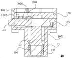
도 10은 본 발명의 실시예2의 배터리 교체 장치의 부분적 구조 모식도이다.
도 11은 본 발명의 실시예2의 배터리 교체 장치의 다른 부분적 구조 모식도이다.
도 12는 본 발명의 실시예2의 배터리 교체 장치중 1차 잠금 메커니즘의 구조 모식도이다.
도 13은 본 발명의 실시예2의 배터리 교체 장치중 2차 잠금 메커니즘의 구조 모식도이다.
도 14는 본 발명의 실시예2의 배터리 교체 장치중 잠금 보호 메커니즘의 단면 모식도이고, 그중, 잠금 샤프트는 연장 상태이다.
도 15는 본 발명의 실시예2의 배터리 교체 장치중 잠금 보호 메커니즘의 분해 구조 모식도이다.
도 16은 본 발명의 실시예2의 배터리 교체 장치중 잠금 보호 메커니즘의 다른 단면 모식도이고, 그중, 잠금 샤프트는 수축 상태이다.
도 17은 본 발명의 실시예2의 잠금 보호 메커니즘중 잠금 핀의 구조 모식도이다.
도 18은 본 발명의 실시예2의 잠금 보호 메커니즘중 동력핀의 구조 모식도이다.
도 19는 본 발명의 실시예2의 배터리 교체 장치중 지지 메커니즘의 구조 모식도이다.1 is a schematic diagram of a three-dimensional structure of a battery holder according to a first embodiment of the present invention.
Fig. 2 is a partial schematic view of a battery holder according to Embodiment 1 of the present invention.
3 is another partial schematic diagram of the battery holder of Embodiment 1 of the present invention, which partially overlaps with FIG. 2 .
4 is a structural schematic diagram of the secondary locking mechanism of the battery holder according to the first embodiment of the present invention.
5 is a structural schematic diagram of a battery holder support device according to Embodiment 1 of the present invention.
6 is a schematic diagram of a three-dimensional structure in which the battery pack assembly and the battery holder of the electric vehicle according to the first embodiment of the present invention are combined.
7 is a three-dimensional structural schematic diagram of the battery pack assembly of the electric vehicle according to the first embodiment of the present invention.
8 is a schematic diagram of a three-dimensional structure of a support part of a battery pack assembly of an electric vehicle according to Embodiment 1 of the present invention.
9 is a schematic diagram of an internal structure of a support part of a battery pack assembly of an electric vehicle according to Embodiment 1 of the present invention.
10 is a partial structural schematic diagram of a battery replacement device according to a second embodiment of the present invention.
11 is another partial structural schematic diagram of the battery replacement device according to the second embodiment of the present invention.
12 is a structural schematic diagram of the primary locking mechanism in the battery replacement device according to the second embodiment of the present invention.
13 is a structural schematic diagram of a secondary locking mechanism in the battery replacement device according to Embodiment 2 of the present invention.
14 is a cross-sectional schematic view of a lock protection mechanism in a battery replacement device according to a second embodiment of the present invention, in which the lock shaft is in an extended state.
15 is an exploded structural schematic diagram of a lock protection mechanism in a battery replacement device according to a second embodiment of the present invention.
16 is another cross-sectional schematic view of the lock protection mechanism in the battery replacement device according to the second embodiment of the present invention, wherein the lock shaft is in a contracted state.
17 is a structural schematic diagram of a locking pin in the locking protection mechanism of Embodiment 2 of the present invention.
18 is a structural schematic diagram of a power pin in the locking protection mechanism of Embodiment 2 of the present invention.
19 is a structural schematic diagram of a support mechanism in the battery replacement device according to the second embodiment of the present invention.
아래, 실시예를 통해 본 발명을 보다 더 한층 설명한다, 하지만 이에 인해 실시예의 범위에 본 발명을 한정하는 것으로 이해되어서는 아니된다.Hereinafter, the present invention will be further described with reference to examples, but it should not be construed as limiting the present invention to the scope of the examples.
실시예1Example 1
도1 내지 도5는 본 발명의 일 실시예에 따른 배터리 홀더의 구조 모식도를 예시하였다. 도1 내지 도5에서 예시 한 바와 같이, 배터리 홀더(10)는 전기 자동차의 차체에 설치되어 배터리 팩(31)을 고정시키는데 사용되고, 즉 퀵 체인지 배터리 팩 혹은 충전 배터리 팩을 설치할 수 있다. 배터리 홀더(10)는 고정 브래킷(11), 잠금 메커니즘 및 다수의 지지 장치(14)를 포함한다. 잠금 메커니즘은 고정 브래킷(11)에 고정 설치된다. 다수의 지지 장치는 고정 브래킷(11)의 배터리 팩을 향한 일 측면에 고정 설치되고, 배터리 팩(31)을 지지하는 다수의 지지 포인트를 제공하는데 사용된다.1 to 5 illustrate a structural schematic diagram of a battery holder according to an embodiment of the present invention. 1 to 5 , the
본 실시예에서, 잠금 메커니즘과 잠금 샤프트를 배합하여 배터리 팩(31)의 잠금을 실현하는 기초상에서, 배터리 팩(31)에 다수의 지지부(34)를 설치하고, 고정 브래킷(11)상에 상기 지지부(34)를 지지하기 위한 다수의 지지 장치(14)를 설치하여, 배터리 팩(31)의 중량이 동시에 다수의 지지 장치(14)와 잠금 메커니즘상에 분포되게 하여, 고정 브래킷(11)은 보다 균일하게 힘을 받아, 배터리 팩(31)이 잠금 메커니즘에 가하는 작용력을 줄이고, 고정 브래킷(11)상의 잠금 메커니즘에 힘이 집중되는 상황을 방지하고, 잠금 메커니즘의 내구한도를 향상시키고, 나아가 안전 성능을 향상시키며, 뿐만 아니라 배터리 팩 어셈블리(30)와 배터리 홀더(10)사이의 연결 강도도 향상시킨다. 또한, 배터리 홀더(10)의 구조가 간단하고, 제조 비용이 낮으며, 동시에, 과한 포지셔닝을 방지하여, 잠금 메커니즘이 잠금 해제 될수 없는 위험을 줄일수 있다.In this embodiment, on the basis of realizing the locking of the
도1에서 예시 한 바와 같이, 고정 브래킷(11)은 프레임 구조이다. 잠금 메커니즘과 다수의 지지 장치(14)는 프레임 구조의 프레임내에 고정된다. 물론, 다른 실시예에서, 고정 브래킷(11)은 환형 측벽을 갖는 디스크 형 구조, 밑면에 개구를 갖는 직육면체 구조 또는 판형 구조 일 수 있으며, 이는 본 발명의 보호 범위를 제한하지 않는다.As illustrated in Fig. 1, the fixing
그중, 고정 브래킷(11)은 프레임(110) 및 임시 커넥터(112)를 포함한다. 프레임(110)중 고정 브래킷의 넓이 방향(W)상에 위치한 일 측면은 브래킷 개구(111)를 가지며, 임시 커넥터(112)는 프레임(110)중 브래킷 개구(111)에 위치한 양 끝의 부위와 분해 가능하게 연결되고, 브래킷 개구(111)를 커버하거나 브래킷 개구(111)내에 위치한다. 배터리 팩(31)과 배터리 홀더(10)가 전기 자동차에 설치 되었을 시, 임시 커넥터(112)를 분해하여, 전기 자동차의 중량을 줄이는데 도움을 준다.Among them, the fixing
또한, 잠금 메커니즘은 일반적으로 잠금 베이스를 포함하고, 잠금 베이스에는 개구와 개구로부터 연장되는 캐비티가 설치되고, 개구는 배터리 팩(31)에 설치 된 잠금 샤프트가 캐비티에 진입하게 하는데 사용된다. 지지 장치(14)에는 지지 홈(142)이 설치되고, 지지 홈(142)의 하부 표면과 캐비티의 하부 표면은 동일한 평면에 위치한다. 이로 인해 배터리 팩(31)이 고정 브래킷(11)내에 보다 견고하게 고정될수 있어, 배터리 팩(31)의 안정적인 움직임을 구현할 수 있다.Further, the locking mechanism generally includes a locking base, and the locking base is provided with an opening and a cavity extending from the opening, and the opening is used to allow the locking shaft installed in the
일 바람직한 구현 방식에서, 도1에서 예시 한 바와 같이, 고정 브래킷(11)중 고정 브래킷의 길이 방향L상에 위치한 양 측면에는 전부 잠금 메커니즘이 설치되고, 같은 측면에 위치한 지지 장치(14)와 잠금 메커니즘사이는 이격 설치된다. 그중, 고정 브래킷(11)의 길이 바향과 전기 자동차의 길이 방향은 대체적으로 같다.In a preferred implementation manner, as illustrated in FIG. 1 , locking mechanisms are installed on both sides of the fixing
더 나아가 바람직하게, 동일한 측면에 위치한 지지 장치(14)와 잠금 메커니즘에서, 고정 브래킷의 길이 방향L상에서, 지지 장치(14)는 고정 브래킷(11)의 양 단부에 분포되고, 잠금 메커니즘은고정 브래킷(11)의 중앙에 위치한다.Further preferably, in the supporting
도1 내지 도3에서 예시 한 바와 같이, 고정 브래킷(11)중 고정 브래킷의 길이 방향L상에 위치한 양 측면에는 전부 2개의 잠금 메커니즘이 설치된다. 고정 브래킷(11)의 같은 측면에 위치한 2개의 잠금 메커니즘은 이격 설치되고, 각기 1차 잠금 메커니즘(12)과 2차 잠금 메커니즘(13)이다. 그중, 2차 잠금 메커니즘(13)과 1차 잠금 메커니즘(12)은 함께 사용되며; 1차 잠금 메커니즘(12)은 공개 번호가CN106427514A인 중국 특허 출원에서 개시된 “잠금 장치”를 참고할 수 있다. 2차 잠금 메커니즘(13)은 배터리 팩(31)에 2차 잠금 또는 잠금 보호 기능을 제공할 수 있고, 1차 잠금 메커니즘(12)이 효력을 잃을 시 배터리 팩(31)이 떨어지는 것을 방지하는데 사용되어, 안전 성능을 향상 시킬수 있다.As exemplified in Figs. 1 to 3, two locking mechanisms are installed on both sides of the fixing
또한, 1차 잠금 메커니즘(12)은 잠금 연결대(120), 적어도 하나의 1차 잠금 빗장(121), 및 적어도 하나의 1차 잠금 베이스(122)를 포함한다. 1차 잠금 베이스(122)는 고정 브래킷(11)에 고정 설치된다. 본 실시예에서, 고정 브래킷(11)의 프레임내의 양 측면에 각각 3개의 1차 잠금 베이스(122)와 3개의 1차 잠금 빗장(121)이 설치된다. 도2와 도3이 바로 그중 일 측면의 부분적 모식도이다.The
도2 내지 도3에서 예시 한 바와 같이, 1차 잠금 베이스(122)에는 1차 개구(123)와 1차 개구(123)로부터 연장되는 1차 캐비티(124)가 설치되고, 1차 개구(123)는 배터리 팩(31)에 설치 된 1차 잠금 샤프트(32)가 1차 캐비티(124)에 진입하게 하는데 사용된다. 잠금 연결대(120)는 적어도 하나의 1차 잠금 빗장(121)과 회전 가능하게 연결되고, 외력의 작용에 의해 1차 잠금 빗장(121)을 회전 시키는데 사용되어, 1차 잠금 빗장(121)이 1차 잠금 베이스(122)를 기준으로 회전하여 1차 잠금 해제 상태와 1차 잠금 상태사이에서 변화하게 할 수 있다. 1차 잠금 빗장(121)이 1차 잠금 상태 일 경우, 1차 잠금 빗장(121)은 1차 잠금 샤프트(32)가 1차 개구(123)로부터 1차 캐비티(124)를 이탈하는 것을 방지할 수 있다. “1차 잠금 상태”는 1차 잠금 메커니즘(12)의 잠금된 상태를 가르키고; “1차 잠금 해제 상태”는 1차 잠금 메커니즘(12)의 잠금 해제된 상태를 가르킨다.2 to 3 , a
도4에서 예시 한 바와 같이, 2차 잠금 메커니즘(13)은 2차 잠금 베이스(131), 2차 잠금 빗장(130) 및 2차 리셋 부품(134)을 포함한다. 2차 잠금 베이스(131)는 고정 브래킷(11)에 고정 설치된다. 2차 잠금 베이스(131)에는 2차 개구(132)와 2차 개구(132)로부터 연장되는 2차 캐비티(133)가 설치되고, 2차 개구(132)는 배터리 팩(31)에 설치 된 2차 잠금 샤프트(33)(구조는 1차 잠금 샤프트(32)와 같거나 비슷하다)가 2차 캐비티(133)에 진입하게 하는데 사용된다.As illustrated in FIG. 4 , the
2차 잠금 빗장(130)은 2차 잠금 베이스(131)를 기준으로 회전하여 잠금 해제 상태와 잠금 상태사이에서 변화한다. 2차 잠금 빗장(130)은 고정적으로 연결된 2차 잠금 빗장 본체(1300)와 2차 잠금 빗장 확장부(1301)를 포함하고, 2차 잠금 빗장 확장부(1301)는 2차 잠금 베이스(131)의 외부에 위치한다. 2차 잠금 빗장(130)이 잠금 상태 일 경우, 2차 잠금 빗장 본체(1300)는 2차 잠금 샤프트(33)가 2차 개구(132)로부터 2차 캐비티(133)를 이탈하는 것을 방지할 수 있다.The
2차 리셋 부품(134)은 2차 잠금 베이스(131)에 설치되고 2차 리셋 부품(134)은 2차 잠금 빗장(130)에 작용한다. 2차 리셋 부품(134)은 탄성 변형을 일으 킬수 있고, 2차 리셋 부품(134)은 2차 잠금 빗장(130)을 잠금 방향에 따라 회전시켜 잠금 해제 상태에서 잠금 상태로 리셋되게 하는데 사용된다.The
2차 잠금 메커니즘(13)에서, 2차 리셋 부품(134)을 설치하여 2차 잠금 빗장(130)이 용이하게 잠금 해제 상태에서 잠금 상태로 리셋 될수 있고, 이로 인해 배터리 팩(31)의 설치 및 잠금이 편리해지고, 2차 리셋 부품(134)의 작용하에서, 2차 잠금 빗장(130)은 쉽게 잠금 해제 상태로 변화되지 않기에, 보다 안정적인 잠금을 구현할 수 있고; 2차 잠금 베이스(131)의 외부에 위치한 2차 잠금 빗장(130) 확장부를 설치하여, 2차 잠금 빗장(130) 확장부에 작용하는 것을 통해 2차 잠금 빗장(130) 본체의 회전을 실현할 수 있기에, 잠금 해제가 편리 해진다.In the
본 실시예에서, 도1 내지 도5에서 예시 한 바와 같이, 지지 홈(142)의 하부 표면과 1차 캐비티(124)의 하부 표면 및 2차 캐비티(133)의 하부 표면은 동일한 평면에 위치한다. 지지 홈(142)의 하부 표면, 1차 캐비티(124)의 하부 표면 및 2차 캐비티(133)의 하부 표면은 전부 사용시 지면에 접근하는 표면을 가르키고, 배터리 팩(31)의 지지부(34), 1차 잠금 샤프트(32) 및 2차 잠금 샤프트(33)의 지지 작용을 하며, 이들은 동일한 평면에 위치하기에 배터리 팩(31)의 안정적인 이동을 실현할 수 있다.In this embodiment, as illustrated in FIGS. 1 to 5 , the lower surface of the
일 바람직한 구현 방식에서, 다수의 지지 장치(14)는 고정 브래킷(11)중 고정 브래킷의 길이 방향L상에 위치한 양 측면에 분포된다. 이로 인해 배터리 팩(31)이 보다 안정적으로 배터리 홀더(10)에 설치되게 할 수 있다. 고정 브래킷(11)의 양 측면에 각각 위치한 지지 장치(14)의 개수는 같으며, 고정 브래킷(11)의 양 측면에 설치된 지지 장치(14)는 일대일로 대응 및 대향하여 설치된다.In one preferred implementation manner, the plurality of supporting
본 실시예에서, 지지 장치(14)와 1차 잠금 베이스(122) 및 2차 잠금 베이스(131)의 구조는 비슷하고, 잠금 작용이 없으며, 배터리 팩(31)의 지지 플랫폼으로만 사용된다. 다른 실시예에서, 다른 유사한 지지 플랫폼을 가진 지지 메커니즘은 전부 적용 가능하다. 지지 장치(14)의 개수는 실제 배터리 팩(31)의 중량에 근거하여 조절할 수 있고, 바람직하게는 평균적으로 하나의 지지 장치(14)가 받는 중량이 25KG을 초과하지 않게 한다.In this embodiment, the structures of the
도5에서 예시한 바와 같이, 지지 장치(14)는 지지 베이스(140)를 포함하고, 지지 베이스(140)에는 지지 개구(141)와 지지 개구(141)로부터 연장되는 지지 홈(142)이 설치되고, 지지 개구(141)는 배터리 팩(31)에 설치 된 지지부(34)가 지지 홈(142)에 진입하게 하는데 사용된다.As illustrated in FIG. 5 , the
잠금 샤프트가 잠금 메커니즘에 진입(본 실시예에서, 1차 잠금 샤프트(32)는 1차 잠금 메커니즘(12)에 진입하고, 2차 잠금 샤프트(33)는 2차 잠금 메커니즘(13)에 진입한다)하는 동시에, 배터리 팩(31)의 지지부(34)는 배터리 홀더(10)의 지지부(142)에 진입하게 되고, 제자리로 잠기는 동시에, 지지부(34)도 마침 지지 베이스(140)의 지지 홈(142)내에 가압 설치되기에, 더 나아가 배터리 팩(31)이 고정 브래킷(11)내에 보다 더 견고하게 고정될 수 있다.The locking shaft enters the locking mechanism (in this embodiment, the
또한, 지지 장치(14)는 탄성 부품(143)을 더 포함하고, 탄성 부품(143)은 적어도 부분적으로 지지 홈(142)내에 위치하고, 탄성 부품(143)은 배터리 팩(31)의 지지부(34)와 인접하는데 사용된다. 탄성 부품(143)은 반드시 지지부(34)와 접촉할 필요는 없지만, 일단 접촉하면, 지지부(34)와 지지 베이스(140)사이의 강한 부딪힘을 방지 할 수 있다.In addition, the
구체적으로, 탄성 부품(143)은 순차적으로 연결되는 탄성 패드(1430), 탄성 핸들(도시 되지 않음) 및 탄성 헤드(1431)를 포함한다. 탄성 패드(1430)는 지지 홈(142)내에 위치하고, 탄성 패드(1430)는 배터리 팩(31)의 지지부(34)와 인접하는데 사용된다. 탄성 핸들은 지지 베이스(140)를 관통 설치되며, 지지 베이스(140)의 벽 부분은 탄성 패드(1430)와 탄성 헤드(1431)사이에 끼움 설치된다. 이로 인해 전체 탄성 부품(143)은 지지 베이스(140)에 견고하게 설치될 수 있다. 탄성 부품(143)은 바람직하게 고무로 제작된다.Specifically, the
더 나아가, 지지 베이스(140)에는 로케이팅 홀(144)이 설치된다. 지지 장치(14)는 로케이팅 핀(145)을 더 포함한다. 로케이팅 핀(145)은 부분적으로 로케이팅 홀(144) 밖에 위치하고, 로케이팅 핀(145)과 로케이팅 홀(144)은 억지 끼워맞춤이다. 지지 장치(14)를 고정 브래킷(11)상에 설치할 시, 로케이팅 핀(145)은 로케이팅에 사용 될 수 있다.Furthermore, a locating
지지 베이스(140)에는 장착 홀(146)이 설치되고, 장착 홀(146)은 나사 홀이고, 지지 베이스(140)는 장착 홀(146)을 통해 분리 가능하게 고정 브래킷(11)과 연결된다. 지지 개구(141)는 벨 마우스이기에, 지지부(34)가 지지 홈(142)에 진입하는 것이 용이해진다.A mounting
도1 내지 도3 및 도5에서 예시 한 바와 같이, 고정 브래킷(11)은 상부 위치 수용 캐비티(도시 되지 않음)를 가지고, 상부 위치 수용 캐비티는 지지 개구(141)의 상부에 위치한다. 상부 위치 수용 캐비티내에는 상부 위치 센서(도시 되지 않음)가 설치되고, 상부 위치 센서는 배터리 팩(31)의 지지부(34)가 지지 개구(141)를 통과하였는 지 여부를 측정하는데 사용되어, 배터리 팩(31)이 전기 자동차의 높이 방향에서 배터리 홀더(10)에 대하여 제자리에 설치되었는지를 판단할 수 있다.1 to 3 and 5 , the fixing
고정 브래킷(11)은 앞부분 위치 수용 캐비티(도시 되지 않음)를 가지고, 앞부분 위치 수용 캐비티는 지지 홈(142)의 앞 단부에 위치한다. 앞 단부는 전기 자동차의 길이 방향상의 차 헤드에 접근하는 위치를 가르킨다. 앞부분 위치 수용 캐비티내에는 앞부분 위치 센서(도시 되지 않음)가 설치되고, 앞부분 위치 센서는 배터리 팩(31)의 지지부(34)가 지지 홈(142)의 앞부분에 진입하였는지 여부를 측정한다. 이로 인해 배터리 팩(31)이 전기 자동차의 길이 방향에서 배터리 홀더(10)에 대하여 제자리에 설치되었는지를 판단할 수 있기에, 전기 자동차가 배터리 팩(31)이 제자리에 설치된 상태에서 주행할 수 있도록 보장하며, 전기 자동차의 안전성을 향상시킨다.The fixing
배터리 홀더(10)는 퀵 체인지 센서(도시 되지 않음)를 더 포함하고, 퀵 체인지 센서는 고정 브래킷(11)에 설치된다. 퀵 체인지 센서는 배터리 교체 장비의 위치 신호를 측정하고, 위치 신호를 제어기에 전송하는데 사용된다. 퀵 체인지 센서 즉 고전압 강제 차단 센서는, 배터리 교체 장비의 위치 신호를 측정하고, 배터리 교체 장비가 소정의 위치에 도달하면, 퀵 체인지 센서는 측정한 위치 신호를 제어기에 전송하여, 배터리 팩(31)의 전원을 차단하여, 배터리 팩(31)이 전원이 차단된 상태에서 교체할 수 있도록 하여, 이의 안전 성능을 향상시킬수 있다.The
본 발명은 전기 자동차를 더 제공하며, 도6에서 예시 한 바와 같이, 전기 자동차는 배터리 팩 어셈블리(30)와 상기 배터리 홀더(10)를 포함하고, 배터리 팩 어셈블리(30)는 배터리 홀더(10)에 설치된다. 본 실시예에서, 전기 자동차는 섀시(도시 되지 않음)를 더 포함하고, 배터리 홀더(10)는 섀시에 고정된다.The present invention further provides an electric vehicle, and as illustrated in FIG. 6 , the electric vehicle includes a
도7에서 예시 한 바와 같이, 배터리 팩 어셈블리(30)는 배터리 팩(31)과 잠금 샤프트(본 실시예에서, 잠금 샤프트는 1차 잠금 샤프트(32)와 2차 잠금 샤프트(33)를 가진다)를 포함하고, 잠금 샤프트는 배터리 팩(31)에 설치된다. 잠금 샤프트는 잠금 메커니즘내(본 실시예에서, 1차 샤프트(32)는 1차 잠금 메커니즘(12)내에 위치하고, 2차 샤프트(33)는 2차 잠금 메커니즘(13)내에 위치한다)에 위치한다.As illustrated in FIG. 7 , the
배터리 팩 어셈블리(30)는 다수의 지지부(34)를 더 포함하고, 다수의 지지부(34)는 배터리 팩(31)에 설치되고, 다수의 지지 장치(14)와 일대일로 대응하며 설치되며, 지지 장치(14)는 대응하는 지지부(34)를 지지하는데 사용된다.The
상기와 같은 배터리 홀더(10)를 포함하는 전기 자동차를 사용하여, 잠금 메커니즘과 잠금 샤프트를 배합하여 배터리 팩(31)의 잠금을 실현하는 기초상에서, 배터리 팩(31)에 다수의 지지부(34)를 설치하고 이를 각각 고정 브래킷(11)상의 다수의 지지 장치(14)와 배합하여, 배터리 팩(31)의 중량이 동시에 다수의 지지 장치(14)와 잠금 메커니즘상에 분포되게 하여, 고정 브래킷(11)은 보다 균일하게 힘을 받아, 배터리 팩(31)이 잠금 메커니즘에 가하는 작용력을 줄이고, 고정 브래킷(11)상의 잠금 메커니즘에 힘이 집중되는 상황을 방지하고, 잠금 메커니즘의 내구한도를 향상시키고, 나아가 안전 성능을 향상시키며, 뿐만 아니라 배터리 팩(31) 어셈블리(30)와 배터리 홀더(10)사이의 연결 강도도 향상시켜, 전기 자동차의 안정 성능을 향상시킨다.On the basis of realizing the locking of the
도5 및 도8 내지 도9에서 예시 한 바와 같이, 지지부(34)는 지지 샤프트(340)를 포함하고, 지지 샤프트(340)는 지지 베이스(140)에 가압 설치되고, 지지 홈(142)내에 위치한다. 잠금 샤프트가 개구로 진입(본 실시예에서, 1차 잠금 샤프트(32)는 1차 개구(123)에 진입하고, 2차 잠금 샤프트(33)는 2차 개구(132)에 진입한다) 할 시, 지지 샤프트(340)는 지지 개구(141)로 진입하게 되고, 잠금 샤프트가 잠금 메커니즘의 캐비티로 진입(본 실시예에서, 1차 잠금 샤프트(32)는 1차 잠금 메커니즘(12)의 1차 캐비티(124)에 진입하고, 2차 잠금 샤프트(33)는 2차 잠금 메커니즘(13)의 2차 캐비티(133)에 진입한다) 할 시, 배터리 팩(31)의 지지 샤프트(340)는 배터리 홀더(10)의 지지 홈(142)에 진입하게 되고, 제자리로 잠기는 동시에, 지지 샤프트(340)도 마침 지지 베이스(140)의 지지 홈(142)내에 가압 설치되기에, 더 나아가 배터리 팩(31)이 고정 브래킷(11)내에 보다 더 견고하게 고정될 수 있다.As illustrated in FIGS. 5 and 8 to 9 , the
또한, 지지부(34)는 샤프트 슬리브(341)를 더 포함하고, 샤프트 슬리브(341)는 지지 샤프트(340)에 회전 가능하게 슬리브 된다. 샤프트 슬리브(341)는 지지 샤프트(340)에 회전 가능하게 슬리브 되어, 샤프트 슬리브(341)가 롤링되게 할 수 있기에, 여러번 설치할 수 있고, 마찰을 감소하여, 지지부의 내구한도를 향상 시킨다. 샤프트 슬리브(341)의 재질은 바람직하게 탄성 재질이다.In addition, the
일 바람직한 구현 방식에서, 지지부(34)는 가스켓(342)을 더 포함하고, 가스켓(342)은 지지 샤프트(340)에 슬리브 설치되고, 샤프트 슬리브(341)의 일 단부에 가압 설치된다. 지지 샤프트(340)는 샤프트 본체(3400)와 플랜지 부(3401)를 포함하고, 플랜지 부(3401)는 샤프트 본체(3400)의 일 단부에 동축으로 설치되고, 샤프트 슬리브(341)는 샤프트 본체(3400)에 슬리브 설치되고, 플랜지 부(3401)는 분해 가능하게 배터리 팩(31)에 연결된다.In one preferred implementation manner, the
더 나아가 바람직하게, 지지 샤프트(340)상에는 전자기 유도 소자(343)가 설치된다. 전자기 유도 소자(343)는 바람직하게 마그네틱 스틸이다. 지지 샤프트(340)중 배터리 팩(31)과 멀어지는 일 단부에 오목 부(344)가 설치되고, 전자기 유도 소자(343)는 오목 부(344)내에 위치한다. 전자기 유도 소자(343)와 지지 샤프트(340)중 배터리 팩(31)과 멀어지는 양 단면은 동일한 평면에 위치한다.Further preferably, an
상부 위치 센서는 전자기 유도 소자(343)에 작용하여, 배터리 팩(31)의 지지부(34)가 지지 개구(141)를 통과하였는 지 여부를 측정하는데 사용된다. 그리하여 배터리 팩(31)이 전기 자동차의 높이 방향에서 배터리 홀더(10)에 대하여 제자리에 설치되었는지를 판단할 수 있다.The upper position sensor acts on the
앞부분 위치 센서는 지지부의 전자기 유도 소자(343)에 작용하여, 배터리 팩(31)의 지지부(34)가 지지 홈(142)의 앞부분에 진입하였는지 여부를 측정한다. 그리하여 배터리 팩(31)이 전기 자동차의 길이 방향에서 배터리 홀더(10)에 대하여 제자리에 설치되었는지를 판단할 수 있기에, 전기 자동차가 배터리 팩(31)이 제자리에 설치된 상태에서 주행할 수 있도록 보장하며, 전기 자동차의 안전성을 향상시킨다.The front position sensor acts on the
이이서, 도4 내지 도5 및 도7을 참고하여, 2차 잠금 메커니즘(13)과 지지 장치(14)의 작업 과정에 대해 간단하게 설명하며, 작업 과정은 주요하게 잠금 해제 과정과 잠금 과정을 포함하고, 그중 초기 상태는 전부 잠금 상태이다.Hereinafter, with reference to FIGS. 4 to 5 and 7 , the working process of the
잠금 과정: 2차 잠금 샤프트(33)는 외력의 작용하에 위로 이동하고, 2차 개구(132)를 거쳐 2차 캐비티(133)에 진입하고, 2차 잠금 샤프트(33)는 2차 잠금 빗장(130)에 작용하여 2차 잠금 빗장(130)이 역시침 방향으로 회전하게 하며, 동시에, 지지부(34)는 외력의 작용하에 위로 이동하고, 지지 개구(141)를 거쳐 지지 홈(142)에 진입하며; 2차 잠금 빗장(130)은 2차 리셋 부품(134)에 작용하여, 2차 리셋 부품(134)의 탄력에 변화를 부여하고; 2차 잠금 빗장(130)이 일정한 각도로 회전 한 후, 2차 캐비티(133)내에 2차 잠금 샤프트(33)가 지날수 있는 통로를 형성하고, 2차 잠금 샤프트(33)는 뒤로부터 앞으로 운동할 수 있고, 동시에, 지지부(34)는 지지 홈(142)내에서 뒤로부터 앞으로 운동할 수 있고; 2차 잠금 샤프트(33)가 다시 2차 잠금 빗장(130)과 접속하지 않게 되면, 2차 잠금 빗장(130)은 리셋 부품의 작용하에 순시침 방향으로 회전하여, 잠금 상태로 리셋되며, 2차 잠금 샤프트(33)가 제자리로 잠기는 동시에, 지지부(34)도 제자리로 설치 된다.Locking process: the
잠금 해제 과정: 2차 잠금 빗장(130)에 작용력을 인가하여, 2차 잠금 빗장(130)이 역시침 방향으로 회전하게 하며; 2차 잠금 빗장(130)은 2차 리셋 부품(134)에 작용하여, 2차 리셋 부품(134)의 탄력에 변화를 부여하고; 2차 잠금 빗장(130)이 일정한 각도로 회전 한 후, 2차 캐비티(133)내에 2차 잠금 샤프트(33)가 지날수 있는 통로를 형성하고; 2차 잠금 샤프트(33)는 앞으로부터 뒤로 운동할 수 있고, 또 2차 개구(132)를 거쳐 아래로 운동하여, 2차 잠금 메커니즘(13)을 이탈하고, 동시에, 지지부(34)는 지지 홈(142)내에서 앞으로부터 뒤로 운동할 수 있고, 또 지지 개구(141)를 거쳐 아래로 운동하여, 지지 장치(14)를 이탈한다.unlocking process: applying an action force to the
실시예2Example 2
본 실시예는 배터리 교체 장치를 개시하며, 전기 자동차에 대해 배터리 교체를 진행하는데 사용된다. 도 10 및 도11에서 예시 한 바와 같이, 배터리 교체 장치는 배터리 팩 홀더(60)(상기 배터리 팩 홀더는 실시예1의 배터리 홀더와 대응된다) 및 차체 측 전기 커넥터(50)를 포함한다. 그중, 배터리 팩 홀더의 고정 브래킷에는 배터리 팩(도면에서 예시 되지 않음)을 수용하는데 사용되는 배터리 팩 수용 캐비티(602)가 형성되고, 배터리 팩의 양 측면에는 잠금 샤프트가 설치되고, 잠금 메커니즘은 배터리 팩 수용 캐비티(602)의 양 측면에 고정 설치된다. 차체 측 전기 커넥터(50)는 배터리 팩 수용 캐비티(602)내의 배터리 팩의 배터리 측 전기 커넥터를 향한 일 측면에 설치된다. 그중, 배터리 팩의 잠금 샤프트가 배터리 팩의 높이 방향에 따라 잠금 메커니즘내에서 제자리로 상승 할 시, 잠금 샤프트의 잠금 메커니즘내에서 배터리 팩의 길이 방향에 따른 잠금 지점까지의 거리는 배터리 측 전기 커넥터와 차체 측 전기 커넥터(50)사이의 상기 배터리 팩의 길이 방향에 따른 간격보다 크다. 잠금 샤프트가 잠금 메커니즘의 잠금 지점에 도달 할 시, 배터리 측 전기 커넥터와 차체 측 전기 커넥터(50)는 억지 끼워맞춤이 된다.This embodiment discloses a battery replacement device, which is used to perform battery replacement for an electric vehicle. As illustrated in FIGS. 10 and 11 , the battery replacement device includes a battery pack holder 60 (the battery pack holder corresponds to the battery holder of Embodiment 1) and a vehicle body side
본 구현 방식에서, 배터리 팩의 잠금 샤프트가 잠금 메커니즘의 잠금 지점에 도달 한 후, 배터리 측 전기 커넥터는 안정적으로 차체 측 전기 커넥터(50)에 전기적 연결되어, 상기 배터리 교체 장치를 사용하여 전기 자동차에 대한 배터리 교체를 진행하는 안정성과 배터리 교체 효율을 향상시킬수 있다.In this implementation manner, after the locking shaft of the battery pack reaches the locking point of the locking mechanism, the battery-side electrical connector is stably electrically connected to the body-side
설명의 편리를 위하여, 잠금 샤프트의 잠금 메커니즘내에서 배터리 팩의 길이 방향에 따른 잠금 지점까지의 거리를 제1거리라고 하고, 배터리 측 전기 커넥터의 고전압 단자 기둥과 차체 측 전기 커넥터(50)의 고전압 단자 기둥사이의 배터리 팩의 길이 방향에 따른 간격은 제2거리라고 한다. 본 구현 방식에서, 차체 측 전기 커넥터(50)의 저전압 단자 기둥의 높이는 차체 측 전기 커넥터(50)의 고전압 단자 기둥의 높이보다 낮고, 차체 측 전기 커넥터(50)의 저전압 단자 기둥과 차체 측 전기 커넥터(50)의 고전압 단자 기둥의 높이 차이는 제1거리와 제2거리사이의 차이보다 작거나 같다.For convenience of description, a distance from the locking point in the longitudinal direction of the battery pack within the locking mechanism of the lock shaft to the locking point is referred to as a first distance, and the high voltage terminal pole of the battery side electrical connector and the high voltage of the vehicle body side
본 구현 방식에서, 상기 높이 차이와 차이값사이의 관계는 차체 측 전기 커넥터(50)와 배터리 측 전기 커넥터가 연결 될 시, 고전압이 먼저 연결되고 저전압이 나중에 연결되게 하고, 저전압 접속후 배터리 팩내의 접속기 제어 스위치는 고전압을 출력할 수 있다. 또한, 차체 측 전기 커넥터(50)와 배터리 측 전기 커넥터가 연결이 단절 될 시, 저전압이 먼저 단절되게 하여 고전압의 단절을 제어할 수 있어, 단절되지 않은 고전압으로 인한 단자 기둥의 아크 소결과 같은 바람직하지 않은 현상이 발생하는 것을 방지한다. 바람직하게, 차체 측 전기 커넥터(50)의 저전압 단자 기둥과 차체 측 전기 커넥터(50)의 고전압 단자 기둥의 높이 차이의 범위는 0 내지 2mm이다. 또한 본 실시예에서, 차체 측 전기 커넥터(50)의 저전압 단자 기둥과 차체 측 전기 커넥터(50)의 고전압 단자 기둥의 높이 차이는 1mm이다.In this implementation method, the relationship between the height difference and the difference value is such that when the vehicle body side
설명해야 할것은, 차체 측 전기 커넥터(50)의 저전압 단자 기둥과 차체 측 전기 커넥터(50)의 고전압 단자 기둥의 높이 차이는 차체 측 전기 커넥터(50)와 배터리 측 전기 커넥터를 실현할 수 있는 기초상에서, 0 및 제1거리와 제2거리사이의 차이의 임의의 수치가 될 수 있다.It should be explained that the height difference between the low-voltage terminal pole of the vehicle-side
다른 대체 가능한 구현 방식에서, 아래와 같이 설정할수도 있다: 배터리 측 전기 커넥터의 저전압 단자 기둥의 높이는 배터리 측 전기 커넥터의 고전압 단자 기둥의 높이보다 낮고, 배터리 측 전기 커넥터의 저전압 단자 기둥과 배터리 측 전기 커넥터의 고전압 단자 기둥의 높이 차이는 제1거리와 제2거리사이의 차이보다 작거나 같다.In another alternative implementation manner, it may be set as follows: the height of the low-voltage terminal pole of the battery-side electrical connector is lower than the height of the high-voltage terminal pole of the battery-side electrical connector, and the low-voltage terminal pole of the battery-side electrical connector and the battery-side electrical connector The difference in height of the high voltage terminal post is less than or equal to the difference between the first distance and the second distance.
또 다른 대체 가능한 구현 방식에서, 아래와 같이 설정할수도 있다: 차체 측 전기 커넥터(50)의 저전압 단자 기둥의 높이는 차체 측 전기 커넥터(50)의 고전압 단자 기둥의 높이보다 낮고, 배터리 측 전기 커넥터의 저전압 단자 기둥의 높이는 배터리 측 전기 커넥터의 고전압 단자 기둥의 높이보다 낮고; 차체 측 전기 커넥터(50)의 저전압 단자 기둥과 차체 측 전기 커넥터(50)의 고전압 단자 기둥의 높이 차이와 배터리 측 전기 커넥터의 저전압 단자 기둥과 배터리 측 전기 커넥터의 고전압 단자 기둥의 높이 차이의 합은 제1거리와 제2거리사이의 차이보다 작거나 같다.In another alternative implementation manner, it may be set as follows: the height of the low-voltage terminal pole of the vehicle-side
본 구현 방식에서, 배터리 측 전기 커넥터와 차체 측 전기 커넥터사이는 플로팅 전기적 연결되고, 도10에서 차체 측 전기 커넥터(50)의 고전압 단자 기둥은 전기 접속 단부(502)와 접선 단부(501)를 가진다. 그중, 고전압 단자 기둥의 전기 접속 단부(502)의 단면에는 홈(도면에서 예시 되지 않음)이 설치되고, 홈은 고전압 단자 기둥의 축 방향에 따라 안으로 오목하게 들어가고, 홈 내에는 전도성 탄성 부품(도면에서 예시 되지 않음)이 설치되고, 전도성 탄성 부품은 전기 접속 단부(502)의 접속면으로부터 돌출된다. 바람직하게, 전도성 탄성 부품은 전도성 스프링이다. 또한, 차체 측 전기 커넥터(50)는 유연성 전기 커넥터와 고전압 플러그를 포함하고, 유연성 전기 커넥터의 일 단부과 고전압 단자 기둥의 접선 단부(501)는 플로팅 전기적 연결된다. 고전압 플러그와 유연성 전기 커넥터의 다른 한 단부는 플로팅 전기적 연결된다.In this implementation manner, a floating electrical connection is made between the battery side electrical connector and the vehicle body side electrical connector, and the high voltage terminal pole of the vehicle body side
본 구현 방식에서, 잠금 메커니즘은 잠금 베이스를 포함하고, 잠금 베이스에는 개구와 개구로부터 연장되는 캐비티가 설치되고, 개구는 잠금 샤프트가 캐비티에 진입하게 하는데 사용된다.배터리 팩 홀더(60)는 상부 위치 수용 캐비티를 가지고, 상부 위치 수용 캐비티는 개구의 상부에 위치하고, 상부 위치 수용 캐비티내에는 상부 위치 센서가 설치되고, 상부 위치 센서는 잠금 샤프트가 개구를 통과하고, 배터리 팩의 높이 방향에 따라 잠금 메커니즘내에서 제자리로 상승되었는지 여부를 측정하는데 사용된다. 배터리 팩 홀더(60)는 앞부분 위치 수용 캐비티를 가지고, 앞부분 위치 수용 캐비티는 캐비티의 앞 단부에 위치하고, 앞부분 위치 수용 캐비티내에는 앞부분 위치 센서가 설치되고, 앞부분 위치 센서는 잠금 샤프트가 캐비티의 앞부분에 진입하고, 배터리 팩의 길이 방향에 따라 잠금 메커니즘내에서 제자리로 잠금되었는지 여부를 측정하는데 사용된다.In this implementation manner, the locking mechanism includes a locking base, and the locking base is provided with an opening and a cavity extending from the opening, and the opening is used to allow the locking shaft to enter the cavity. having a receiving cavity, the upper position receiving cavity is located at the upper part of the opening, the upper position sensor is installed in the upper position receiving cavity, the upper position sensor has a locking shaft passing through the opening, the locking mechanism according to the height direction of the battery pack It is used to measure whether or not it has been raised into place within the body. The
본 구현 방식에서, 상부 위치 센서는 잠금 샤프트가 잠금 메커니즘내에서 제자리로 상승되었는지 여부를 측정할 수 있고, 앞부분 위치 센서는 잠금 샤프트가 캐비티의 앞 단부에서 제자리에 잠금되고 잠금 포인트에 도달하였는지 여부를 측정할 수 있고, 상부 위치 센서와 앞부분 위치 센서는 배터리 팩의 잠금 안정성을 향상시킬수 있기에, 차체 측 전기 커넥터(50)와 베터리 측 전기 커넥터의 전기적 연결의 안정성을 향상시키는데 도움이 되고, 더 나아가 전기 자동차의 배터리 교체의 안정성을 향상시키는데 도움이 된다.In this implementation manner, the upper position sensor can measure whether the lock shaft has been raised into position within the locking mechanism, and the front position sensor can detect whether the lock shaft has been locked in place at the front end of the cavity and reached the lock point. Since the upper position sensor and the front position sensor can improve the locking stability of the battery pack, it helps to improve the stability of the electrical connection between the body-side
도10에서 예시 한 바와 같이, 배터리 팩 홀더(60)에는 와이어 하니스(70)가 더 설치되고, 와이어 하니스(70)는 상부 위치 센서가 측정한 상부 제자리 신호 및 앞부분 위치 센서가 측정한 앞부분 제자리 신호를 배터리 교체 장치로 전송하는데 사용된다.As illustrated in FIG. 10 , a
도10 및 도11을 참조하여 이해 하는것은, 배터리 팩 홀더(60)중 배터리 팩 홀더(60)의 길이 방향상에 위치한 양 측면에는 전부 2개의 잠금 메커니즘이 설치되고, 배터리 팩 홀더(60)의 같은 측면에 위치한 2개의 잠금 메커니즘은 이격 설치되고, 2개의 잠금 메커니즘은 각각 1차 잠금 메커니즘(20)과 2차 잠금 메커니즘(30)이다. 차체 측 전기 커넥터(50)는 배터리 팩 홀더(60)중 배터리 팩 홀더(60)의 넓이 방향상의 일 측벽에 설치된다. 배터리 팩 홀더(60)의 길이 방향은 배터리 팩의 길이 방향에 대해 평행된다. 그중, 1차 잠금 메커니즘(20)이 효력을 잃을 시, 2차 잠금 메커니즘(30)이 작용하여, 배터리 팩이 잠금 샤프트를 잠그어, 배터리 팩이 떨어지는 것을 방지하기에, 더 나아가 전기 자동차의 배터리 교체의 안정성을 향상시키는데 도움이 된다.To understand with reference to FIGS. 10 and 11 , two locking mechanisms are installed on both sides of the
도10 내지 도12를 참조하여 이해 하는것은, 1차 잠금 메커니즘(20)은 잠금 연결대(201), 적어도 하나의 1차 잠금 빗장(202), 적어도 하나의 1차 잠금 베이스(203)를 포함하고, 1차 잠금 베이스(203)는 배터리 홀더(60)에 고정 설치되고, 1차 잠금 베이스(203)에는 1차 개구와 1차 개구로부터 연장되는 1차 캐비티(204)가 설치되고, 1차 개구는 배터리 팩의 1차 잠금 샤프트가 1차 캐비티(204)에 진입하게 하는데 사용되고, 잠금 연결대(201)는 적어도 하나의 1차 잠금 빗장(202)과 회전 가능하게 연결되고, 외력의 작용에 의해 1차 잠금 빗장(202)을 회전 시키는데 사용되어, 1차 잠금 빗장(202)이 1차 잠금 베이스(203)를 기준으로 회전하여 1차 잠금 해제 상태와 1차 잠금 상태사이에서 변화하게 하며, 1차 잠금 빗장(202)이 상기 1차 잠금 상태 일 경우, 1차 잠금 빗장(202)은 1차 잠금 샤프트가 1차 개구로부터 1차 캐비티(204)를 이탈하는 것을 방지할 수 있다. 잠금 연결대(201)의 1차 잠금 베이스(203)를 향한 일 측면에 잠금 해제 블록(205)이 더 설치되고, 잠금 해제 블록(205)은 잠금 연결대(201)로부터 밖으로 형성 된 아크형 돌기이고, 잠금 해제 블록(205)의 상단은 잠금 연결대(201)에 향하여 오목하게 들어간 내부 아크 홈이다. 그중, 본 구현 방식에서, 1차 잠금 빗장(202)과 1차 잠금 베이스(203)의 개수는 각각 3개이다.10 to 12 , it is understood that the
도10 및 도13을 참조하여 이해 하는것은, 2차 잠금 메커니즘(30)은 2차 잠금 베이스(301), 2차 잠금 빗장(302) 및 2차 리셋 부품(303)을 포함한다. 그중, 2차 잠금 베이스(301)는 배터리 팩 홀더(60)에 고정 설치되고, 2차 잠금 베이스(301)에는 2차 개구(3011)와 2차 개구(3011)로부터 연장되는 2차 캐비티(3012)가 설치되고, 2차 개구(3011)는 배터리 팩의 2차 잠금 샤프트가 2차 캐비티(3012)에 진입하게 하는데 사용된다. 2차 잠금 빗장(302)은 2차 잠금 베이스(301)를 기준으로 회전하여 2차 잠금 해제 상태와 2차 잠금 상태사이에서 변화할 수 있으며, 2차 잠금 빗장(302)은 고정 연결된 2차 잠금 빗장 본체(3021)와 2차 잠금 빗장 확장부(3022)를 포함하고, 2차 잠금 빗장(302) 확장부는 2차 잠금 베이스(301)의 외부에 위치하고, 2차 잠금 빗장(302)이 2차 잠금 상태 일 경우, 2차 잠금 빗장 본체(3021)는 2차 잠금 샤프트가 2차 개구(3011)로부터 2차 캐비티(3012)를 이탈하는 것을 방지할 수 있다. 2차 리셋 부품(303)은 2차 잠금 베이스(301)에 설치되고 2차 리셋 부품(303)은 2차 잠금 빗장(302)에 작용하며, 2차 리셋 부품(303)은 탄성 변형을 일으 킬수 있고, 2차 리셋 부품(303)은 2차 잠금 빗장(302)을 잠금 방향에 따라 회전시켜 2차 잠금 해제 상태에서 2차 잠금 상태로 리셋되게 하는데 사용된다.As will be understood with reference to FIGS. 10 and 13 , the
도10, 도 11 및 도14 내지 도16을 참조하여 이해 하는것은, 배터리 교체 장치는 잠금 보호 메커니즘(10)을 더 포함한다. 잠금 보호 메커니즘(10)은 배터리 팩 홀더(60)의 1차 잠금 메커니즘과 대향하는 일 측에 고정 설치되고, 잠금 보호 메커니즘(10)은 잠금 연결대(201)의 이동경로에 설치되어, 잠금 연결대(201)가 1차 잠금 메커니즘의 1차 잠금 베이스(203)에 대한 운동을 제한하는데 사용된다. 잠금 보호 메커니즘(10)은 잠금 연결대(201)에 대하여 제1위치와 제2위치사이를 이동할 수 있다. 그중, 잠금 보호 메커니즘(10)이 제1위치에 있을 시, 잠금 보호 메커니즘(10)은 잠금 연결대(201)에 작용하여, 1차 잠금 베이스(203)에 대한 잠금 연결대(201)의 운동을 제한하고; 잠금 보호 메커니즘(10)이 제2위치에 있을 시, 잠금 보호 메커니즘(10)은 잠금 연결대(201)와 분리되어, 잠금 연결대(201)가 1차 잠금 베이스(203)에 대한 운동을 허용한다.It will be understood with reference to FIGS. 10 , 11 and 14 to 16 , the battery replacement device further includes a
1차 잠금 메커니즘(20)이 잠금 샤프트를 잠글 시, 잠금 보호 메커니즘(10)은1차 잠금 베이스(203)에 대한 잠금 연결대(201)의 운동을 제한하기에, 1차 잠금 메커니즘(20)의 잠금 효력을 향상시킬수 있어, 1차 잠금 메커니즘(20)이 비교적 안정하게 잠금 샤프트를 잠글수 있게 할 수 있다. 이로 인해, 전기 자동차의 배터리 교체 안정성을 보다 향상시키는데 도움이 된다When the
도 11 및 도14 내지 도18을 참조하여 이해 하는것은, 잠금 보호 메커니즘(10)은 제1하부 케이싱(101) 및 잠금 핀(102)을 포함한다. 제1하부 케이싱(101)은 분리 가능하게 1차 잠금 베이스(203)중 잠금 샤프트와 대향하는 일 측면에 연결되며, 제1하부 케이싱(101)의 내부에는 제1 홀딩 캐비티(1011)를 구비하고, 하부 케이싱의 측벽은 제1 홀딩 캐비티(1011)와 연통되는 관통 홀(1012)을 구비한다. 잠금 핀(102)은 제1 홀딩 캐비티(1011)내에 위치하고, 관통 홀(1012)에 관통 설치되어, 연장 상태와 수축 상태 사이에서 전환될 수 있다. 그중, 잠금 핀(102)이 연장 상태일 시, 잠금 핀(102)은 제1위치에 위치하고; 잠금 핀(102)이 수축 상태일 시, 잠금 핀(102)은 제2위치에 위치한다. 잠금 핀(102)의 연장과 수축을 제어하는 것을 통해 잠금 핀(102)의 제1위치와 제2위치사이의 전환을 실현할 수 있고, 구조가 간단하며, 실현이 용이하다. 또한, 도2에서 예시 한 바와 같이, 배터리 팩 홀더(60)에는 홀(601)이 설치되고, 잠금 핀(102)은 홀(601)을 통해 제1위치와 제2위치사이에서 전환한다.As will be understood with reference to FIGS. 11 and 14 to 18 , the
잠금 보호 메커니즘(10)은 동력 핀(103), 제1 전자기 유도 소자(104) 및 제1 탄성 소자(105)를 더 포함한다. 동력 핀(103)은 잠금 핀(102)에 작용하고, 동력 핀(103)은 잠금 핀(102)에 대하여 운동할 수 있어, 잠금 핀(102)과 접합하거나 분리될 수 있다. 제1 전자기 유도 소자(104)는 동력 핀(103)에 설치되고, 제1 전자기 유도 소자(104)는 외부 전자기 장비의 작용하에, 동력 핀(103)을 구동하여 잠금 핀(102)에 잠금 핀(102)의 수축 방향에 따른 작용력을 인가하는데 사용된다. 제1 탄성 소자(105)는 잠금 핀(102)의 캐비티와 멀어지는 일 단부에 연결되고, 제1 탄성 소자(105)는 잠금 핀(102)와 제1 홀딩 캐비티(1011)의 내벽면사이에 인접되고, 제1 탄성 소자(105)는 잠금 핀(102)에 잠금 핀(102)의 연장 방향에 따른 작용력을 인가하는데 사용된다. 그중, 제1 전자기 유도 소자(104)와 외부 전자기 장비가 접합 될 시, 동력 핀(103)은 잠금 핀(102)과 분리 되고, 잠금 핀(102)에 수축 방향에 따른 작용력을 인가하여, 잠금 핀(102)이 수축 상태에 놓이게 하고; 제1 전자기 유도 소자(104)와 외부 전자기 장비가 분리 될 시, 제1 탄성 소자(105)는 잠금 핀(102)에 연장 방향에 따른 작용력을 인가하여, 동력 핀(103)과 잠금 핀(102)이 접합되어, 잠금 핀(102)이 연장 상태에 놓이게 한다.The
본 구현 방식에서, 제1 전자기 유도 소자(104)와 외부 전자기 장비가 접합 될 시, 동력 핀(103)은 잠금 핀(102)과 멀어지는 방향으로 운동하고, 잠금 핀(102)에 수축 방향에 따른 작용력을 인가하여, 잠금 핀(102)이 수축되게 하고, 잠금 핀(102)은 제1 탄성 소자(105)를 압출하고, 동력 핀(103과 잠금 핀(102)이 완전히 분리 된후, 제1 탄성 소자(105)는 잠금 핀(102)에 회복력을 제공하여, 잠금 핀(102)이 동력 핀(103)과 접합되는 위치로 돌아오게 한다. 제1 전자기 유도 소자(104)와 외부 전자기 장비가 분리 될 시, 동력 핀(103)은 잠금 핀(102)에 접근하는 방향으로 운동하여, 잠금 핀(102)과 접합하여, 잠금 핀(102)이 연장 상태에 놓이게 한다. 또한, 본 구현 방식에서, 자기장 접합의 방식을 사용하여 동력 핀(103)과 잠금 핀(102)의 접합과 분리를 제어하여, 잠금 핀(102)의 연장과 수축을 제어하고, 제어 방법이 간단하고, 제어 효율이 높다.In the present implementation method, when the first
잠금 핀(102)은 집행 부(1021) 및 연결 부(1022)를 가진다. 연결 부(1022)는 집행 부(1021)의 1차 캐비티(204)와 멀어지는 일 단부에 연결되고, 연결 부(1022)는 제2 홀딩 캐비티(1023)를 가지고, 제2 홀딩 캐비티(1023)는 동력 핀(103)을 홀딩하는데 사용된다. 그중, 제1 탄성 소자(105)는 연결 부(1022)의 집행 부(1021)와 멀어지는 일 단부에 연결되고, 제1 탄성 소자(105)는 연결 부(1022)와 제1 홀딩 캐비티(1011)의 내벽면사이에 인접되고, 제1 탄성 소자(105)는 연결 부(1022)에 연장 방향에 따른 작용력을 인가한다. 동력 핀(103)과 잠금 핀(102)이 접합 될 시, 동력 핀(103)에서 잠금 핀(102)에 접근하는 일 단부는 제2 홀딩 캐비티(1023)에 끼움 연결되며, 이는 내부 삽입식 연결에 속하며, 차지하는 공간이 비교적 적다.The
본 구현 방식에서, 연결 부(1022)의 길이 방향과 동력 핀(103)의 높이 방향은 제1 각도를 형성하고, 제2 홀딩 캐비티(1023)는 동력 핀(103)의 높이 방향에 따라 연장되어, 동력 핀(103)이 잠금 핀(102)에 대하여 동력 핀(103)의 높이 방향에 따라 운동하게 한다.In this implementation manner, the longitudinal direction of the connecting
동력 핀(103)은 이의 높이 방향에 따라 헤드 단부와 꼬리 단부를 가지며, 동력 핀(103)의 헤드 단부는 제2 홀딩 캐비티(1023)내에 삽입 설치되며, 제1 전자기 유도 소자(104)는 동력 핀(103)의 꼬리 단부에 설치된다. 제2 홀딩 캐비티(1023)의 내벽면에는 제1경사 부(1024)를 가지고, 동력 핀(103)의 헤드 단부는 제1경사 부(1024)와 매칭되는 제2경사 부(1032)를 가진다. 그중, 동력 핀(103)과 잠금 핀(102)이 접합 될 시, 제1경사 부(1024)는 제2경사 부(1032)에 부착되고; 동력 핀(103)과 잠금 핀(102)이 분리 될 시, 제2경사 부(1032)는 제1경사 부(1024)에 대해 아래로 운동하고, 잠금 핀(102)에 수축 방향에 따른 작용력을 인가하여, 잠금 핀(102)이 수축 상태에 놓이게 한다.The
본 구현 방식에서, 교묘하게 제1경사 부(1024)와 제2경사 부(1032)가 협동하여, 동력 핀(103)이 잠금 핀(102)에서 멀어지는 방향으로 운동할 시, 제1경사 부(1024)는 제2경사 부(1032)에 대해 슬라이드 되고, 제1경사 부(1024)가 제2경사 부(1032)에 인가하는 마찰력은 수축 방향에 따른 분력으로 분해할 수 있고, 상기 분력의 작용하에, 잠금 핀(102)은 수축된다.In this implementation manner, the first
제2 홀딩 캐비티(1023)의 내벽면은 오목 부(1025)를 더 가지고, 동력 핀(103)의 헤드 단부는 오목 부(1025)와 매칭되는 돌출 부를 가진다. 제2 홀딩 캐비티(1023)의 내벽면은 2개의 제1경사 부(1024)를 가지고, 2개의 제1경사 부(1024)는 오목 부(1025)의 양 측면에 대향하여 설치된다. 본 구현 방식에서, 오목 부(1025)는 동력 핀(103)에 대하여 위치 제한 작용을 할 수 있고, 이는 동력 핀(103)과 잠금 핀(102)의 안정적인 접합에 도움이 되어, 잠금 핀(102)의 안정적인 연장에 도움이 되고, 잠금 샤프트의 안정적인 잠금에 도움이 된다.The inner wall surface of the
제1 전자기 유도 소자(104)는 동력 핀(103)의 꼬리 단부에 삽입 설치된다. 이러한 설치는 제1 전자기 유도 소자(104)가 동력 핀(103)의 외부에서 별도의 공간을 차지하지 않게 하며, 이는 공간 이용율을 향상 시키는데 도움이 된다. 또한, 제1 전자기 유도 소자(104)를 보호하는데 도움이 된다.The first
또한, 동력 핀(103)의 꼬리 단부에는 제2 탄성 소자(106)가 슬리브 설치되며, 제2 탄성 소자(106)는 동력 핀(103)에 연결 부(1022)에 접근하는 방향에 따른 작용력을 인가하고; 그중, 제2 탄성 소자(106)가 동력 핀(103)에 인가하는 작용력은 동력 핀(103)의 중력보다 크다. 본 구현 방식에서, 동력 핀(103)과 잠금 핀(102)이 접합 할 시, 제2 탄성 소자(106)는 동력 핀(103)에 작용력을 인가하여, 동력 핀(103)이 중력의 작용하에 떨어지지 않도록 하기에, 더 나아가 동력 핀(103)과 잠금 핀(102)의 접합 안정성을 향상시킬수 있다. 동력 핀(103)이 잠금 핀(102)에 접근하는 방향으로 운동 해야 할 시, 제2 탄성 소자(106)가 동력 핀(103)에 인가하는 작용력은 동력 핀(103)의 중력을 극복하여, 동력 핀(103)이 더 안정적으로 잠금 핀(102)에 접근하는 방향에 따라 운동할 수 있게 한다.In addition, the second
잠금 보호 메커니즘(10)은 제2하부 케이싱(107)을 더 포함하고, 제2하부 케이싱(107)은 제1하부 케이싱(101)의 밑부분에 연결되고, 제2하부 케이싱(107)은 제3 홀딩 캐비티(1071)를 가지고, 제3 홀딩 캐비티(1071)와 제1 홀딩 캐비티(1011)는 서로 연통되며, 동력 핀(103)은 제3 홀딩 캐비티(1071)내에 위치한다. 제2하부 케이싱(107)의 중심 축라인과 제1하부 케이싱(101)의 중심 축라인사이에는 제2각도가 형성되고, 제2각도는 제1각도와 같다.The
또한, 동력 핀(103)의 외측벽과 제2 탄성 소자(106)의 양 단부가 대응되는 위치에는 전부 차단 부(1031)가 설치되고, 제2 탄성 소자(106)는 2개의 차단 부(1031)사이에 끼움 설치된다. 즉, 본 구현 방식에서, 제2 탄성 소자(106)는 전체적으로 동력 핀(103)의 외벽면에 슬리브 설치되며, 제2 탄성 소자(106)는 스프링이다. 그중, 차단 부(1031)의 주요한 작용은 제2 탄성 소자(106)의 위치를 찾아내여, 제2 탄성 소자(106)가 동력 핀(103)의 높이 방향에 따른 운동을 제한하는 것이다.In addition, all blocking
또한, 잠금 보호 메커니즘(10)은 상부 케이싱(108)을 더 포함하고, 상부 케이싱(108)은 제1하부 케이싱(101)에 가압 설치되고, 분해 가능하게 연결된다. 상부 케이싱(108)은 잠금 핀(102), 동력 핀(103)을 고정및 보호하는 작용을 한다. 상부 케이싱(108)은 제4 수용 캐비티(1081)를 가지고, 제4 수용 캐비티(1081)내에는 제1센서(1082)가 설치되고, 집행 부(1021)에는 제2 전자기 유도 소자(1026)가 설치된다. 그중, 제1센서(1082)는 제2 전자기 유도 소자(1026)에 작용하여, 집행 부(1021)가 연장 상태에 있음을 측정한다. 제4 수용 캐비티(1081)내에는 제2센서(1083)가 더 설치되고, 제2센서(1083)는 제2 전자기 유도 소자(1026)에 작용하여, 집행 부(1021)가 수축 상태에 있음을 측정한다. 그중, 제1센서(1082)에 비하여, 제2센서(1083)는 동력 핀(103)에 더 접근한다. 제1센서(1082), 제2센서(1083)와 제2 전자기 유도 소자(1026)를 통해 안정적으로 잠금 핀(102)이 언제 연장 상태 및 수축 상태인지를 측정할 수 있기에, 1차 잠금 메커니즘(20)이 배터리 팩에 대한 잠금 해제와 잠금을 실현하는데 도움이 된다. 또한, 본 구현 방식에서, 제1 전자기 유도 소자(104) 및 제2 전자기 유도 소자(1026)는 전부 마그네틱 스틸이다.In addition, the
또한, 본 구현 방식에서, 잠금 보호 메커니즘(10)은 자기장으로 동력 핀(103)과 접합하는 방식으로 잠금 핀(102)의 연장과 수축을 실현하고, 잠금 핀(102)의 연장과 수축은 동일한 직선 방향상에서 진행된다. 다른 대체 가능한 구현 방식에서, 다른 구동 방식(자기장을 제외한 구동 방식)을 사용하여 잠금 핀(102)의 연장과 수축을 실현할 수 있고, 잠금 핀(102)의 행동 경로를 곡선으로 설정할 수 있고, 다른 비 잠금 핀(102) 구조, 예를 들면 크랭크 메커니즘, 로커 메커니즘을 통하여, 제1위치와 제2위치사이에서의 잠금 보호 메커니즘의 전환을 실현할 수 있다.Further, in this implementation manner, the
도10 및 도19를 참조하여 이해 하는것은, 배터리 교체 장치는 다수의 지지 메커니즘(40)을 더 포함한다. 다수의 지지 메커니즘(40)은 배터리 팩 홀더(60)의 배터리 팩을 향한 일 측면에 고정 설치되고, 다수의 지지 메커니즘(40)은 배터리 팩을 지지하는 다수의 지지 포인트를 제공하는데 사용된다. 구체적으로, 지지 메커니즘(40)은 지지 베이스(401)를 포함하고, 지지 베이스(401)에는 지지 개구(402)와 지지 개구(402)로부터 연장되는 지지 홈(403)이 설치되고, 지지 개구(402)는 배터리 팩에 설치 된 지지부가 지지 홈(403)에 진입하게 하는데 사용된다. 다수의 지지 메커니즘(40)은 배터리 팩 홀더(60)중 배터리 팩 홀더(60)의 길이 방향상에 위치한 양 측에 분포되고, 배터리 팩 홀더(60)의 양 측면에 설치된 지지 메커니즘(40)은 일대일로 대응 및 대향하여 설치된다. 배터리 팩 홀더(60)중 배터리 팩 홀더(60)의 길이 방향상에 위치한 양 측면에는 전부 잠금 메커니즘이 설치되고, 같은 측면에 위치한 지지 메커니즘(40)과 잠금 메커니즘사이는 이격 설치된다. 지지 메커니즘(40)은 배터리 팩을 지지하는 작용을 하여, 배터리 팩과 배터리 팩 홀더(60)의 설치가 용이하게 실현될 수 있고, 잠금 메커니즘의 잠금 효력을 향상시키는데 도움이 되어, 전기 자동차의 배터리 교체 안정성을 향상시키는데 도움이 된다.It is understood with reference to FIGS. 10 and 19 that the battery replacement device further includes a plurality of
또한, 본 구현 방식에서, 도10에서의 배터리 팩 홀더(60)에는 배터리 교체 센서(도면에서 예시 되지 않음)가 더 설치되고, 배터리 교체 센서는 배터리 교체 장치를 감지하고, 차체 측 전기 커넥터(50)와 배터리 측 전기 커넥터사이의 전기적 연결의 단절을 제어하는데 사용된다. 배터리 교체 장비가 배터리 팩을 배터리 팩 홀더(60)에서 분해할 시, 배터리 교체 센서는 차체 측 전기 커넥터(50)와 배터리 측 전기 커넥터사이의 전기적 연결의 단절시킬수 있어, 전기 자동차를 보호하는 작용을 할 수 있다.In addition, in the present implementation manner, a battery replacement sensor (not illustrated in the drawing) is further installed in the
본 실시예에서는 배터리 교체 장치의 설치 방법을 더 개시하고, 설치 방법은,In this embodiment, the installation method of the battery replacement device is further disclosed, the installation method comprising:
단계1, 잠금 샤프트가 배터리 팩의 높이 방향에서 잠금 메커니즘내에 제자리로 상승 될 때까지, 배터리 팩을 배터리 팩 홀더의 하부로부터 배터리 팩의 높이 방향에 따라 배터리 팩 홀더에 넣는 단계;Step 1, inserting the battery pack into the battery pack holder from the bottom of the battery pack holder along the height direction of the battery pack until the lock shaft is lifted into place in the locking mechanism in the height direction of the battery pack;
단계2, 잠금 샤프트가 배터리 팩의 길이 방향에서 잠금 메커니즘내에 잠금 포인트로 도달 할 때까지, 배터리 팩이 이의 길이 방향에 따라 앞으로 운동하게 하는 단계를 포함한다.Step 2, causing the battery pack to move forward along its longitudinal direction until the locking shaft reaches a locking point in the locking mechanism in the longitudinal direction of the battery pack.
본 실시예의 배터리 교체 장치에 대하여, 배터리 팩의 잠금 샤프트가 잠금 메커니즘내에서 제자리로 잠긴 후, 배터리 측 전기 커넥터는 안정적으로 차체 측 전기 커넥터와 전기적 연결 될수 있기에, 상기 배터리 교체 장치를 사용하여 전기 자동차에 대한 배터리 교체를 진행하는 안정성과 배터리 교체 효율을 향상시킬수 있다.With respect to the battery replacement device of this embodiment, after the locking shaft of the battery pack is locked in place in the locking mechanism, the battery side electrical connector can be stably electrically connected with the body side electrical connector, so that the battery replacement device can be used for an electric vehicle It is possible to improve the stability and battery replacement efficiency in proceeding with the battery replacement.
이상 본 발명의 구체적인 실시형태를 설명하였지만, 본 분야의 통상의 기술자는 이는 단지 예를 들어 설명한 것일 뿐 본 발명의 보호범위는 첨부된 청구범위에 의해 한정됨을 이해해야 한다. 본 분야의 통상의 기술자는 본 발명의 원리 및 실질을 벗어나지 않는 전제 하에 이러한 실시형태에 대해 여러가지 변경 또는 수정을 진행할 수 있지만 이러한 변경 및 수정은 모두 본 발명의 보호범위에 속해야 한다.Although specific embodiments of the present invention have been described above, those of ordinary skill in the art should understand that this is merely an example and that the protection scope of the present invention is limited by the appended claims. A person skilled in the art may make various changes or modifications to these embodiments without departing from the spirit and substance of the present invention, but all such changes and modifications should fall within the protection scope of the present invention.
실시예1
배터리 홀더: 10; 고정 브래킷: 11; 프레임: 110; 브래킷 개구: 111; 임시 커넥터: 112; 1차 잠금 메커니즘: 12; 1차 잠금 연결대: 120; 1차 잠금 빗장: 121; 1차 잠금 베이스: 122; 1차 개구: 123; 1차 캐비티: 124; 2차 잠금 메커니즘: 13; 2차 잠금 빗장: 130; 2차 잠금 빗장 본체: 1300; 2차 잠금 빗장 확장부: 1301; 2차 잠금 베이스: 131; 2차 개구: 132; 2차 캐비티: 133; 2차 리셋 부품: 134; 지지 장치: 14; 지지 베이스: 140; 지지 개구: 141; 지지 홈: 142; 탄성 부품: 143; 탄성 패드: 1430;
탄성 헤드: 1431; 로케이팅 홀: 144; 로케이팅 핀: 145; 장착 홀: 146; 배터리 팩 어셈블리: 30; 배터리 팩: 31; 1차 잠금 샤프트: 32; 2차 잠금 샤프트: 33; 지지부: 34; 지지 샤프트: 340; 샤프트 본체: 3400; 플랜지 부: 3401; 샤프트 슬리브: 341; 가스켓: 342; 전자기 유도 소자: 343; 오목 부: 344; 고정 브래킷의 넓이 방향: W; 고정 브래킷의 길이 방향: L
실시예2
10 잠금 보호 메커니즘; 101 제1하부 케이싱; 1011 제1 홀딩 캐비티;1012 관통 홀; 102 잠금 핀; 1021 집행 부; 1022 연결 부; 1023 제2 홀딩 캐비티; 1024 제1경사 부; 1025 오목 부; 1026 제2 전자기 유도 소자; 103 동력 핀; 1031 차단 부; 1032 제2 경사 부; 104 제1 전자기 유도 소자; 105 제1 탄성 소자; 106 제2 탄성 소자; 107 제2 하부 케이싱; 1071 제3 수용 캐비티; 108 상부 케이싱; 1081 제4 수용 캐비티; 1082 제1센서; 1083 제2센서; 20 1차 잠금 메커니즘; 201 잠금 연결대; 202 1차 잠금 빗장; 203 1차 잠금 베이스; 204 1차 캐비티; 205 잠금 해제 블록; 30 2차 잠금 메커니즘; 301 2차 잠금 베이스; 3011 2차 개구; 3012 2차 캐비티; 302 2차 잠금 빗장; 3021 2차 잠금 빗장 본체; 3022 2차 잠금 빗장 확장부; 303 2차 리셋 부품; 40 지지 메커니즘; 401 지지 베이스; 402 지지 개구; 403 지지 홈; 50 차체 측 전기 커넥터; 501 접선 단부; 502 전기 접속 단부; 60 배터리 팩 홀더; 601 홀; 602 배터리 팩 수용 캐비티; 70 와이어 하니스Example 1
Battery Holder: 10; Fixed bracket: 11; Frame: 110; bracket opening: 111; Temporary connector: 112; Primary locking mechanism: 12; Primary locking joint: 120; Primary Locking Latch: 121; Primary Lock Base: 122; primary opening: 123; primary cavity: 124; secondary locking mechanism: 13; Second Locking Latch: 130; secondary locking latch body: 1300; secondary locking latch extension: 1301; secondary locking base: 131; secondary opening: 132; secondary cavity: 133; 2nd reset part: 134; support device: 14; support base: 140; support opening: 141; support groove: 142; elastic parts: 143; Elastic Pad: 1430;
Elastic head: 1431; Locating hole: 144; locating pin: 145; mounting holes: 146; Battery pack assembly: 30; Battery Pack: 31; Primary lock shaft: 32; secondary lock shaft: 33; support: 34; support shaft: 340; Shaft body: 3400; Flange part: 3401; shaft sleeve: 341; gasket: 342; electromagnetic induction element: 343; concave: 344; Width direction of fixing bracket: W; Length of fixing bracket: L
Example 2
10 locking protection mechanism; 101 first lower casing; 1011 first holding cavity; 1012 through hole; 102 locking pins; 1021 Executive Department; 1022 connection; 1023 second holding cavity; 1024 first ramp; 1025 concave; 1026 second electromagnetic induction element; 103 power pins; 1031 blocking unit; 1032 second inclined portion; 104 first electromagnetic induction element; 105 first elastic element; 106 second elastic element; 107 second lower casing; 1071 third receiving cavity; 108 upper casing; 1081 fourth receiving cavity; 1082 first sensor; 1083 second sensor; 20 primary locking mechanism; 201 locking joint; 202 primary locking latch; 203 primary locking base; 204 primary cavity; 205 unlock block; 30 secondary locking mechanism; 301 secondary locking base; 3011 secondary opening; 3012 secondary cavity; 302 secondary locking latch; 3021 secondary locking latch body; 3022 secondary locking latch extension; 303 secondary reset component; 40 support mechanism; 401 support base; 402 support opening; 403 support groove; 50 body-side electrical connector; 501 tangential end; 502 electrical connection end; 60 battery pack holder; 601 Hall; 602 battery pack receiving cavity; 70 wire harness
Claims (28)
다수의 지지 장치를 더 포함하고, 상기 지지 장치는 상기 고정 브래킷의 배터리 팩을 향한 일 측면에 고정 설치되고, 다수의 상기 지지 장치는 상기 배터리 팩을 지지하는 다수의 지지 포인트를 제공하고,
다수의 상기 지지 장치는 상기 고정 브래킷 중 상기 고정 브래킷의 길이 방향 상에 위치한 양 측에 분포되고,
상기 고정 브래킷 중 상기 고정 브래킷의 길이 방향 상에 위치한 양 측면에는 전부 상기 잠금 메커니즘이 설치되고, 상기 잠금 메커니즘은 1차 잠금 메커니즘 및 2차 잠금 메커니즘이고,
상기 2차 잠금 메커니즘은,
2차 잠금 베이스를 포함하고, 상기 2차 잠금 베이스는 상기 고정 브래킷에 고정 설치되며, 상기 2차 잠금 베이스에는 2차 개구와 상기 2차 개구로부터 연장되는 2차 캐비티가 설치되고, 상기 2차 개구는 상기 배터리 팩에 설치된 2차 잠금 샤프트가 상기 2차 캐비티에 진입하게 하는 데 사용되고,
2차 잠금 빗장을 포함하고, 상기 2차 잠금 빗장은 상기 2차 잠금 베이스를 기준으로 회전하여 잠금 해제 상태와 잠금 상태 사이에서 변화하며, 상기 2차 잠금 빗장은 고정 연결된 2차 잠금 빗장 본체와 2차 잠금 빗장 확장부를 포함하고, 상기 2차 잠금 빗장 확장부는 상기 2차 잠금 베이스의 외부에 위치하고, 상기 2차 잠금 빗장이 잠금 상태일 경우, 상기 2차 잠금 빗장 본체는 상기 2차 잠금 샤프트가 상기 2차 개구로부터 상기 2차 캐비티를 이탈하는 것을 방지할 수 있고, 및,
2차 리셋 부품을 포함하고, 상기 2차 리셋 부품은 상기 2차 잠금 베이스에 설치되고 상기 리셋 부품은 상기 2차 잠금 빗장에 작용하며, 상기 2차 리셋 부품은 탄성 변형을 일으킬 수 있고, 상기 2차 리셋 부품은 상기 2차 잠금 빗장을 잠금 방향에 따라 회전시켜 상기 잠금 해제 상태에서 상기 잠금 상태로 리셋되게 하는 데 사용되는 것을 특징으로 하는 배터리 홀더. It is installed on the body of the electric vehicle and used to fix the battery pack, comprising a fixing bracket and a locking mechanism, wherein the locking mechanism is fixedly installed on the fixing bracket,
Further comprising a plurality of support devices, the support devices are fixedly installed on one side of the fixing bracket facing the battery pack, the plurality of support devices provide a plurality of support points for supporting the battery pack,
A plurality of the support devices are distributed on both sides of the fixing bracket located in the longitudinal direction of the fixing bracket,
The locking mechanism is installed on both sides of the fixing bracket in the longitudinal direction of the fixing bracket, the locking mechanism being a primary locking mechanism and a secondary locking mechanism,
The secondary locking mechanism comprises:
a secondary locking base, wherein the secondary locking base is fixedly installed on the fixing bracket, the secondary locking base includes a secondary opening and a secondary cavity extending from the secondary opening, the secondary opening is used to allow the secondary locking shaft installed in the battery pack to enter the secondary cavity,
a secondary locking latch, wherein the secondary locking latch rotates with respect to the secondary locking base to change between an unlocked state and a locked state, wherein the secondary locking latch is fixedly connected to the secondary locking latch body and 2 and a secondary locking latch extension, wherein the secondary locking latch extension is located outside the secondary locking base, and when the secondary locking latch is in a locked state, the secondary locking latch body is configured such that the secondary locking shaft is connected to the secondary locking shaft. escape of the secondary cavity from the secondary opening, and
a secondary reset part, wherein the secondary reset part is installed on the secondary lock base, the reset part acts on the secondary lock latch, the secondary reset part can cause elastic deformation; and a car reset component is used to rotate the secondary locking latch along a locking direction to reset it from the unlocked state to the locked state.
상기 잠금 메커니즘은 잠금 베이스를 포함하고, 상기 잠금 베이스에는 개구와 상기 개구로부터 연장되는 캐비티가 설치되고, 상기 개구는 상기 배터리 팩에 설치된 잠금 샤프트가 상기 캐비티에 진입하게 하는 데 사용되며;
상기 지지 장치에는 지지 홈이 설치되고, 상기 지지 홈의 하부 표면과 상기 캐비티의 하부 표면은 동일한 평면에 위치하는 것을 특징으로 하는 배터리 홀더.According to claim 1,
the locking mechanism includes a locking base, the locking base being provided with an opening and a cavity extending from the opening, the opening being used to allow a locking shaft installed in the battery pack to enter the cavity;
The support device is provided with a support groove, and a lower surface of the support groove and a lower surface of the cavity are located on the same plane.
상기 지지 장치에는 지지 홈이 설치되고;
상기 지지 장치는 지지 베이스를 포함하고, 상기 지지 베이스에는 지지 개구와 상기 지지 개구로부터 연장되는 상기 지지 홈이 설치되고, 상기 지지 개구는 상기 배터리 팩에 설치된 지지부가 상기 지지 홈에 진입하게 하는 데 사용되는 것을 특징으로 하는 배터리 홀더.According to claim 1,
the support device is provided with a support groove;
The support device includes a support base, wherein the support base is provided with a support opening and the support groove extending from the support opening, the support opening being used to allow a support installed in the battery pack to enter the support groove Battery holder characterized in that it becomes.
상기 고정 브래킷은 상부 위치 수용 캐비티를 가지고, 상기 상부 위치 수용 캐비티는 상기 지지 개구의 상부에 위치하고, 상기 상부 위치 수용 캐비티 내에는 상부 위치 센서가 설치되고, 상기 상부 위치 센서는 상기 배터리 팩의 지지부가 상기 지지 개구를 통과하였는지 여부를 측정하는 데 사용되는 것을 특징으로 하는 배터리 홀더.4. The method of claim 3,
The fixing bracket has an upper position accommodating cavity, the upper position accommodating cavity is located above the support opening, and an upper position sensor is installed in the upper position accommodating cavity, and the upper position sensor includes a support part of the battery pack. A battery holder, characterized in that used to measure whether it has passed through the support opening.
상기 고정 브래킷은 앞부분 위치 수용 캐비티를 가지고, 상기 앞부분 위치 수용 캐비티는 상기 지지 홈의 앞 단부에 위치하고, 상기 앞부분 위치 수용 캐비티 내에는 앞부분 위치 센서가 설치되고, 상기 앞부분 위치 센서는 상기 배터리 팩의 지지부가 상기 지지 홈의 앞 단부에 진입하였는지 여부를 측정하는 데 사용되는 것을 특징으로 하는 배터리 홀더.4. The method of claim 3,
The fixing bracket has a front position receiving cavity, the front position receiving cavity is located at the front end of the support groove, a front position sensor is installed in the front position receiving cavity, and the front position sensor supports the battery pack Battery holder, characterized in that it is used to measure whether the portion has entered the front end of the support groove.
상기 지지 장치는 탄성 부품을 더 포함하고, 상기 탄성 부품은 적어도 부분적으로 상기 지지 홈 내에 위치하고, 상기 탄성 부품은 상기 배터리 팩의 지지부와 인접시키는 데 사용되는 것을 특징으로 하는 배터리 홀더.4. The method of claim 3,
wherein the support device further comprises a resilient component, the resilient component being at least partially located in the support groove, the resilient component being used to abut the support of the battery pack.
상기 탄성 부품은 순차적으로 연결되는 탄성 패드, 탄성 핸들 및 탄성 헤드를 포함하고;
상기 탄성 패드는 상기 지지 홈 내에 위치하고, 상기 탄성 패드는 상기 배터리 팩의 지지부와 인접시키는 데 사용되며;
상기 탄성 핸들은 상기 지지 베이스에 관통 설치되며, 상기 지지 베이스의 벽 부분은 상기 탄성 패드와 상기 탄성 헤드 사이에 끼움 설치되는 것을 특징으로 하는 배터리 홀더. 7. The method of claim 6,
the elastic part includes an elastic pad, an elastic handle, and an elastic head, which are sequentially connected;
the elastic pad is located in the support groove, and the elastic pad is used to abut the support portion of the battery pack;
The elastic handle is installed through the support base, and a wall portion of the support base is fitted between the elastic pad and the elastic head.
상기 지지 베이스에는 로케이팅 홀이 설치되고, 상기 지지 장치는 로케이팅 핀을 더 포함하고, 상기 로케이팅 핀은 부분적으로 상기 로케이팅 홀 밖에 위치하고, 상기 로케이팅 핀과 상기 로케이팅 홀은 억지 끼워맞춤인 것을 특징으로 하는 배터리 홀더.4. The method of claim 3,
The support base is provided with a locating hole, the support device further includes a locating pin, the locating pin is located partially outside the locating hole, the locating pin and the locating hole are interference fit Battery holder, characterized in that.
상기 지지 베이스에는 장착 홀이 설치되고, 상기 장착 홀은 나사 홀이고, 상기 지지 베이스는 상기 장착 홀을 통해 분리 가능하게 상기 고정 브래킷과 연결되는 것을 특징으로 하는 배터리 홀더.4. The method of claim 3,
A mounting hole is provided in the support base, the mounting hole is a screw hole, and the support base is detachably connected to the fixing bracket through the mounting hole.
상기 지지 개구는 벨 마우스인 것을 특징으로 하는 배터리 홀더.4. The method of claim 3,
The battery holder, characterized in that the support opening is a bell mouth.
상기 고정 브래킷의 양 측에 각각 위치한 상기 지지 장치의 개수는 같으며, 상기 고정 브래킷의 양 측에 설치된 상기 지지 장치는 일대일로 대응 및 대향하여 설치되는 것을 특징으로 하는 배터리 홀더.According to claim 1,
The number of the support devices respectively located on both sides of the fixing bracket is the same, and the support devices installed on both sides of the fixing bracket are installed in a one-to-one correspondence and opposite to each other.
같은 측에 위치한 상기 지지 장치와 상기 잠금 메커니즘에서, 상기 고정 브래킷의 길이 방향에서, 상기 지지 장치는 상기 고정 브래킷의 양 끝에 분포되고, 상기 잠금 메커니즘은 상기 고정 브래킷의 중간부분에 위치하는 것을 특징으로 하는 배터리 홀더.According to claim 1,
In the supporting device and the locking mechanism located on the same side, in the longitudinal direction of the fixing bracket, the supporting device is distributed at both ends of the fixing bracket, and the locking mechanism is located in the middle of the fixing bracket. battery holder.
상기 1차 잠금 메커니즘은 잠금 연결대, 적어도 하나의 1차 잠금 빗장, 적어도 하나의 1차 잠금 베이스를 포함하고, 상기 1차 잠금 베이스는 상기 고정 브래킷에 고정 설치되고, 상기 1차 잠금 베이스에는 1차 개구와 상기 1차 개구로부터 연장되는 1차 캐비티가 설치되고, 상기 1차 개구는 상기 배터리 팩에 설치된 1차 잠금 샤프트가 상기 1차 캐비티에 진입하게 하는 데 사용되고, 잠금 연결대는 적어도 하나의 상기 1차 잠금 빗장과 회전 가능하게 연결되고, 외력의 작용에 의해 상기 1차 잠금 빗장을 회전 시키는 데 사용되어, 상기 1차 잠금 빗장이 상기 1차 잠금 베이스를 기준으로 회전하여 1차 잠금 해제 상태와 1차 잠금 상태 사이에서 변화하게 하며, 상기 1차 잠금 빗장이 상기 1차 잠금 상태일 경우, 상기 1차 잠금 빗장은 상기 1차 잠금 샤프트가 상기 1차 개구로부터 상기 1차 캐비티를 이탈하는 것을 방지할 수 있는 것을 특징으로 하는 배터리 홀더.According to claim 1,
The primary locking mechanism includes a locking connecting rod, at least one primary locking latch, and at least one primary locking base, wherein the primary locking base is fixedly installed on the fixing bracket, and the primary locking base has a primary locking base. An opening and a primary cavity extending from the primary opening are provided, wherein the primary opening is used to allow a primary locking shaft installed in the battery pack to enter the primary cavity, and a locking connector includes at least one of the first openings. It is rotatably connected to the primary locking latch and is used to rotate the primary locking latch by the action of an external force, so that the primary locking latch rotates with respect to the primary locking base to change the primary unlocking state and 1 change between primary locking states, wherein when the primary locking latch is in the primary locked state, the primary locking latch prevents the primary locking shaft from leaving the primary cavity from the primary opening A battery holder, characterized in that it can.
상기 고정 브래킷은 프레임 및 임시 커넥터를 포함하고, 상기 프레임 중 상기 고정 브래킷의 넓이 방향 상에 위치한 일 측은 브래킷 개구를 가지며, 상기 임시 커넥터는 상기 프레임 중 상기 브래킷 개구에 위치한 양 끝의 부위와 분해 가능하게 연결되고, 상기 브래킷 개구를 커버하거나 상기 브래킷 개구 내에 위치하는 것을 특징으로 하는 배터리 홀더.14. The method according to any one of claims 1 to 13,
The fixing bracket includes a frame and a temporary connector, one side of the frame positioned in the width direction of the fixing bracket has a bracket opening, and the temporary connector is disassembled from both ends of the frame located in the bracket opening A battery holder, characterized in that the battery holder is connected to the said bracket opening, characterized in that it covers or is located in the bracket opening.
상기 배터리 홀더는 퀵 체인지 센서를 더 포함하고, 상기 퀵 체인지 센서는 상기 고정 브래킷에 설치되고, 상기 퀵 체인지 센서는 배터리 교체 장비의 위치 신호를 측정하고, 상기 위치 신호를 제어기에 전송하는 데 사용되는 것을 특징으로 하는 배터리 홀더.14. The method according to any one of claims 1 to 13,
The battery holder further includes a quick change sensor, the quick change sensor is installed on the fixing bracket, the quick change sensor is used to measure the position signal of the battery replacement equipment, and transmit the position signal to the controller Battery holder, characterized in that.
상기 배터리 팩 어셈블리는 다수의 지지부를 더 포함하고, 다수의 상기 지지부는 상기 배터리 팩에 설치되고, 다수의 상기 지지 장치와 일대일로 대응하여 설치되며, 상기 지지 장치는 대응하는 상기 지지부를 지지하는 데 사용되는 것을 특징으로 하는 전기 자동차.a battery pack assembly, wherein the battery pack assembly includes a battery pack and a lock shaft, the lock shaft is installed on the battery pack, and further includes the battery holder of claim 1 , wherein the battery pack assembly includes the battery installed in the holder, wherein the lock shaft is located within the lock mechanism;
The battery pack assembly further includes a plurality of support parts, a plurality of the support parts are installed on the battery pack, and are installed in a one-to-one correspondence with a plurality of the support devices, and the support devices are configured to support the corresponding support parts. An electric vehicle characterized in that it is used.
상기 잠금 메커니즘은 잠금 베이스를 포함하고, 상기 잠금 베이스에는 개구와 상기 개구로부터 연장되는 캐비티가 설치되고, 상기 개구는 상기 잠금 샤프트가 상기 캐비티에 진입하게 하는 데 사용되며, 상기 잠금 샤프트는 상기 캐비티 내에 위치하고;
상기 지지 장치는 지지 베이스를 포함하고, 상기 지지 베이스에는 지지 개구와 상기 지지 개구로부터 연장되는 지지 홈이 설치되고, 상기 지지 개구는 상기 지지부가 상기 지지 홈에 진입하게 하는 데 사용되며;
상기 지지부는 지지 샤프트를 포함하고, 상기 지지 샤프트는 상기 지지 베이스에 가압 설치되고, 상기 지지 홈 내에 위치하는 것을 특징으로 하는 전기 자동차.17. The method of claim 16,
The locking mechanism includes a locking base, the locking base having an opening and a cavity extending from the opening, the opening being used to allow the locking shaft to enter the cavity, the locking shaft being disposed in the cavity located;
the support device includes a support base, wherein the support base is provided with a support opening and a support groove extending from the support opening, the support opening being used for allowing the support part to enter the support groove;
The support part includes a support shaft, wherein the support shaft is installed under pressure on the support base and is located in the support groove.
상기 지지부는 샤프트 슬리브를 더 포함하고, 상기 샤프트 슬리브는 상기 지지 샤프트에 회전 가능하게 슬리브 설치되는 것을 특징으로 하는 전기 자동차.18. The method of claim 17,
The support part further includes a shaft sleeve, wherein the shaft sleeve is rotatably sleeved on the support shaft.
상기 샤프트 슬리브의 재질은 탄성 재질인 것을 특징으로 하는 전기 자동차.19. The method of claim 18,
The electric vehicle, characterized in that the material of the shaft sleeve is an elastic material.
상기 지지부는 가스켓을 더 포함하고, 상기 가스켓은 상기 지지 샤프트에 슬리브 설치되고, 상기 샤프트 슬리브의 일 단부에 가압 설치되는 것을 특징으로 하는 전기 자동차.19. The method of claim 18,
The support part further includes a gasket, wherein the gasket is sleeve-installed on the support shaft and installed under pressure at one end of the shaft sleeve.
상기 지지 샤프트는 샤프트 본체와 플랜지 부를 포함하고, 상기 플랜지 부는 상기 샤프트 본체의 일 단부에 동축으로 설치되고, 상기 샤프트 슬리브는 상기 샤프트 본체에 슬리브 설치되고, 상기 플랜지 부는 분해 가능하게 상기 배터리 팩에 연결되는 것을 특징으로 하는 전기 자동차.19. The method of claim 18,
The support shaft includes a shaft body and a flange part, the flange part is installed coaxially to one end of the shaft body, the shaft sleeve is sleeve installed to the shaft body, and the flange part is detachably connected to the battery pack An electric vehicle characterized in that it becomes.
상기 지지 샤프트상에는 전자기 유도 소자가 설치되는 것을 특징으로 하는 전기 자동차.18. The method of claim 17,
An electromagnetic induction element is installed on the support shaft.
상기 고정 브래킷은 상부 위치 수용 캐비티를 가지고, 상기 상부 위치 수용 캐비티는 상기 지지 개구의 상부에 위치하고, 상기 상부 위치 수용 캐비티 내에는 상부 위치 센서가 설치되고, 상기 상부 위치 센서는 상기 전자기 유도 소자에 작용하여, 상기 배터리 팩의 지지부가 상기 지지 개구를 통과하였는지 여부를 측정하는 데 사용되는 것을 특징으로 하는 전기 자동차.23. The method of claim 22,
The fixing bracket has an upper position receiving cavity, the upper position receiving cavity is located above the support opening, and an upper position sensor is installed in the upper position receiving cavity, the upper position sensor acting on the electromagnetic induction element to measure whether the support portion of the battery pack has passed through the support opening.
상기 고정 브래킷은 앞부분 위치 수용 캐비티를 가지고, 상기 앞부분 위치 수용 캐비티는 상기 지지 홈의 앞 단부에 위치하고, 상기 앞부분 위치 수용 캐비티 내에는 앞부분 위치 센서가 설치되고, 상기 앞부분 위치 센서는 상기 전자기 유도 소자에 작용하여, 상기 배터리 팩의 지지부가 상기 지지 홈의 앞 단부에 진입하였는지 여부를 측정하는 데 사용되는 것을 특징으로 하는 전기 자동차.24. The method of claim 22 or 23,
The fixing bracket has a front position receiving cavity, the front position receiving cavity is located at a front end of the support groove, a front position sensor is installed in the front position receiving cavity, and the front position sensor is connected to the electromagnetic induction element by acting, it is used to measure whether the support part of the battery pack has entered the front end of the support groove.
상기 지지 샤프트 중 상기 배터리 팩과 멀어지는 일 단부에 오목부가 설치되고, 상기 전자기 유도 소자는 상기 오목부 내에 위치하고, 상기 전자기 유도 소자와 상기 지지 샤프트 중 상기 배터리 팩과 멀어지는 양 단면은 동일한 평면에 위치하는 것을 특징으로 하는 전기 자동차.23. The method of claim 22,
A concave portion is provided at one end of the support shaft away from the battery pack, the electromagnetic induction element is located in the concave portion, and both end surfaces of the electromagnetic induction element and the support shaft away from the battery pack are located on the same plane Electric vehicle characterized in that.
상기 전자기 유도 소자는 마그네틱 스틸인 것을 특징으로 하는 전기 자동차.23. The method of claim 22,
The electromagnetic induction element is an electric vehicle, characterized in that the magnetic steel.
상기 지지부는,
지지 샤프트를 포함하고, 상기 지지 샤프트는 상기 지지 장치에 가압 설치되고;
샤프트 슬리브를 포함하고, 상기 샤프트 슬리브는 회전 가능하게 상기 지지 샤프트에 슬리브 설치되는 것을 특징으로 하는 전기 자동차.17. The method of claim 16,
The support part,
a support shaft, the support shaft being pressurized to the support device;
and a shaft sleeve, wherein the shaft sleeve is rotatably installed on the support shaft.
상기 전기 자동차는 섀시를 더 포함하고, 상기 배터리 홀더는 상기 섀시에 고정되는 것을 특징으로 하는 전기 자동차.
28. The method according to any one of claims 16 to 23 and 25 to 27,
The electric vehicle further comprises a chassis, wherein the battery holder is fixed to the chassis.
Applications Claiming Priority (6)
| Application Number | Priority Date | Filing Date | Title |
|---|---|---|---|
| CN201711486896.9A CN109994667B (en) | 2017-12-29 | 2017-12-29 | Battery fixing seat and electric vehicle comprising same |
| CN201711482966.3 | 2017-12-29 | ||
| CN201711482966.3A CN109987067B (en) | 2017-12-29 | 2017-12-29 | Battery replacement device and installation method thereof |
| CN201711486896.9 | 2017-12-29 | ||
| PCT/CN2018/125679 WO2019129285A1 (en) | 2017-12-29 | 2018-12-29 | Battery holder, power transfer device, electric vehicle and installation method for electric vehicle |
| KR1020207022033A KR102359015B1 (en) | 2017-12-29 | 2018-12-29 | A battery holder, a battery replacement device, an electric vehicle, and an installation method of an electric vehicle. |
Related Parent Applications (1)
| Application Number | Title | Priority Date | Filing Date |
|---|---|---|---|
| KR1020207022033A Division KR102359015B1 (en) | 2017-12-29 | 2018-12-29 | A battery holder, a battery replacement device, an electric vehicle, and an installation method of an electric vehicle. |
Publications (2)
| Publication Number | Publication Date |
|---|---|
| KR20220018632A KR20220018632A (en) | 2022-02-15 |
| KR102437941B1 true KR102437941B1 (en) | 2022-08-29 |
Family
ID=67063210
Family Applications (3)
| Application Number | Title | Priority Date | Filing Date |
|---|---|---|---|
| KR1020207022033A KR102359015B1 (en) | 2017-12-29 | 2018-12-29 | A battery holder, a battery replacement device, an electric vehicle, and an installation method of an electric vehicle. |
| KR1020227003183A KR102437941B1 (en) | 2017-12-29 | 2018-12-29 | Battery holder, battery exchange device, electric vehicle and installation method for electric vehicle |
| KR1020227003182A KR102533870B1 (en) | 2017-12-29 | 2018-12-29 | Battery holder, battery exchange device, electric vehicle and installation method for electric vehicle |
Family Applications Before (1)
| Application Number | Title | Priority Date | Filing Date |
|---|---|---|---|
| KR1020207022033A KR102359015B1 (en) | 2017-12-29 | 2018-12-29 | A battery holder, a battery replacement device, an electric vehicle, and an installation method of an electric vehicle. |
Family Applications After (1)
| Application Number | Title | Priority Date | Filing Date |
|---|---|---|---|
| KR1020227003182A KR102533870B1 (en) | 2017-12-29 | 2018-12-29 | Battery holder, battery exchange device, electric vehicle and installation method for electric vehicle |
Country Status (13)
| Country | Link |
|---|---|
| US (3) | US11588338B2 (en) |
| EP (1) | EP3734690A4 (en) |
| JP (3) | JP6997326B2 (en) |
| KR (3) | KR102359015B1 (en) |
| AU (1) | AU2018396985B2 (en) |
| BR (1) | BR112020013376B1 (en) |
| CA (1) | CA3087315C (en) |
| MX (3) | MX2020006899A (en) |
| MY (1) | MY188815A (en) |
| PH (1) | PH12020551016A1 (en) |
| SG (1) | SG11202006165SA (en) |
| WO (1) | WO2019129285A1 (en) |
| ZA (1) | ZA202004455B (en) |
Families Citing this family (16)
| Publication number | Priority date | Publication date | Assignee | Title |
|---|---|---|---|---|
| CN114148212A (en) * | 2016-11-21 | 2022-03-08 | 上海电巴新能源科技有限公司 | Locking device and electric automobile |
| EP3821480B1 (en) * | 2019-09-11 | 2022-05-18 | SZ DJI Technology Co., Ltd. | Power supply mounting position detecting device, method, and power supply |
| CN112838304B (en) * | 2019-11-01 | 2022-12-02 | 爱驰汽车有限公司 | Battery pack quick-release assembly and use method thereof |
| CN112776582A (en) * | 2019-11-06 | 2021-05-11 | 重庆科米罗新能源汽车有限公司 | Adopt quick mechanism that trades of antidetonation type of doublestage location to insert soon |
| CN113120086A (en) * | 2019-12-31 | 2021-07-16 | 奥动新能源汽车科技有限公司 | Automobile body support, automobile body support subassembly and electric automobile with dismantlement formula back beam |
| KR20210114625A (en) * | 2020-03-11 | 2021-09-24 | 현대자동차주식회사 | Battery release system for vehicle |
| US11685502B2 (en) * | 2020-06-30 | 2023-06-27 | Textron Innovations Inc. | Modular hybrid airframe structure for battery thermal event protection and repair |
| CN112018291B (en) * | 2020-09-04 | 2022-08-30 | 重庆峘能电动车科技有限公司 | Battery box frame unit, battery box frame module and new energy automobile |
| HUE064368T2 (en) * | 2020-09-30 | 2024-03-28 | Contemporary Amperex Technology Co Ltd | Holder, battery assembly, and power utilization device |
| EP4007055A4 (en) * | 2020-09-30 | 2022-08-10 | Contemporary Amperex Technology Co., Limited | Support, battery assembly, electric device, and battery assembly manufacturing method and device |
| KR102569233B1 (en) * | 2021-03-25 | 2023-08-22 | 비나텍주식회사 | Pouch type battery include internal frame with pressurizing function |
| KR102556095B1 (en) * | 2021-03-30 | 2023-07-14 | 비나텍주식회사 | Pouch type battery include internal frame |
| CN117795757A (en) | 2022-02-14 | 2024-03-29 | 株式会社Lg新能源 | Prismatic secondary battery including stacked cells |
| US20230261338A1 (en) | 2022-02-14 | 2023-08-17 | Lg Energy Solution, Ltd. | Electrode structure and prismatic battery including the same |
| CN114520392B (en) * | 2022-03-03 | 2024-04-12 | 中国第一汽车股份有限公司 | Battery quick change device and have its vehicle |
| CN115837832A (en) * | 2022-06-30 | 2023-03-24 | 奥动新能源汽车科技有限公司 | A automobile body support and electric vehicle for installing battery package |
Citations (4)
| Publication number | Priority date | Publication date | Assignee | Title |
|---|---|---|---|---|
| JP2000334001A (en) | 2000-01-01 | 2000-12-05 | Yamaha Motor Co Ltd | Motorized wheelchair |
| JP2011049151A (en) | 2009-07-30 | 2011-03-10 | Sanyo Electric Co Ltd | Battery pack attached to/detached from electric vehicle, and the electric vehicle equipped with the same |
| CN105109321A (en) | 2015-08-20 | 2015-12-02 | 北京新能源汽车股份有限公司 | Locking mechanism, quick battery pack replacing device with same and vehicle |
| CN205033926U (en) | 2015-08-20 | 2016-02-17 | 北京新能源汽车股份有限公司 | A trade battery installation device and electric automobile for electric automobile |
Family Cites Families (28)
| Publication number | Priority date | Publication date | Assignee | Title |
|---|---|---|---|---|
| JP2003118397A (en) | 2001-10-10 | 2003-04-23 | Toyota Industries Corp | Mounting structure for battery device |
| GB0210886D0 (en) * | 2002-05-13 | 2002-06-19 | Zap Wireless Technologies Ltd | Improvements relating to contact-less power transfer |
| JP2010125867A (en) | 2008-11-25 | 2010-06-10 | Nissan Motor Co Ltd | Battery fixing structure of electric powered vehicle |
| JP2010129181A (en) | 2008-11-25 | 2010-06-10 | Nissan Motor Co Ltd | Battery fastening structure and battery fastening method of motor-driven vehicle |
| JP2010208406A (en) | 2009-03-09 | 2010-09-24 | Toyota Motor Corp | Carriage for unloading on-vehicle body, system for unloading on-vehicle body, and structure for mounting on-vehicle body |
| FR2946593B1 (en) | 2009-06-16 | 2013-02-08 | Renault Sas | SECURE ARRANGEMENT OF A BATTERY IN A MOTOR VEHICLE |
| JP5532903B2 (en) | 2009-12-18 | 2014-06-25 | 日産自動車株式会社 | Electric vehicle battery connector structure |
| JP5999914B2 (en) * | 2012-02-09 | 2016-09-28 | 本田技研工業株式会社 | Electric vehicle power supply |
| CN202764685U (en) | 2012-07-24 | 2013-03-06 | 上海电巴新能源科技有限公司 | Clamping mechanism and locking device |
| CN202743033U (en) | 2012-09-18 | 2013-02-20 | 国家电网公司 | Locking device and battery box |
| CN203135093U (en) | 2012-12-19 | 2013-08-14 | 李福青 | Connecting device for rapid replacing power battery of electric vehicle |
| CN203637545U (en) | 2014-01-07 | 2014-06-11 | 深圳精智机器有限公司 | Battery locking device of vehicle |
| CN205255985U (en) | 2015-10-19 | 2016-05-25 | 北京新能源汽车股份有限公司 | Electric automobile's battery package quick change control system |
| CN105150820B (en) | 2015-10-19 | 2018-05-08 | 北京新能源汽车股份有限公司 | The battery pack quick change control system of electric automobile |
| CN106809188A (en) | 2015-11-30 | 2017-06-09 | 鸿富锦精密工业(深圳)有限公司 | Battery replacing vehicle for electric system and application method |
| CN105459975B (en) | 2015-12-31 | 2017-09-15 | 天津布尔科技有限公司 | A kind of batteries of electric automobile, which is changed planes, sets up and its application method |
| US10312490B2 (en) * | 2016-04-05 | 2019-06-04 | Ford Global Technologies, Llc | Vent devices for electrified vehicle battery packs |
| CN205736878U (en) | 2016-05-06 | 2016-11-30 | 臻昊(北京)新能源科技有限公司 | A kind of generalization monoblock type battery change system for electric automobile |
| CN105857048B (en) | 2016-05-06 | 2018-01-05 | 臻昊(北京)新能源科技有限公司 | A kind of generalization monoblock type battery change system for electric automobile |
| JP2017204386A (en) * | 2016-05-11 | 2017-11-16 | トヨタ自動車株式会社 | Under-floor structure of vehicle |
| CN106025131B (en) * | 2016-07-04 | 2019-09-17 | 北京海博思创科技有限公司 | Battery pack fixing device and vehicle-mounted power supply unit |
| CN205985557U (en) | 2016-09-09 | 2017-02-22 | 上海电巴新能源科技有限公司 | Electric connector's electric connection structure and electric connector |
| CN206186768U (en) * | 2016-11-21 | 2017-05-24 | 上海电巴新能源科技有限公司 | Locking means and electric automobile |
| CN114148212A (en) | 2016-11-21 | 2022-03-08 | 上海电巴新能源科技有限公司 | Locking device and electric automobile |
| KR101998565B1 (en) * | 2017-12-27 | 2019-07-11 | (주)동희산업 | Battery case for electric vehicle |
| CN109994667B (en) | 2017-12-29 | 2020-09-08 | 上海电巴新能源科技有限公司 | Battery fixing seat and electric vehicle comprising same |
| CN115008994A (en) * | 2017-12-29 | 2022-09-06 | 上海电巴新能源科技有限公司 | Battery box unlocking device, battery box and battery box quick battery changing system |
| CN109987067B (en) | 2017-12-29 | 2022-06-21 | 上海电巴新能源科技有限公司 | Battery replacement device and installation method thereof |
-
2018
- 2018-12-29 KR KR1020207022033A patent/KR102359015B1/en active IP Right Grant
- 2018-12-29 WO PCT/CN2018/125679 patent/WO2019129285A1/en active Application Filing
- 2018-12-29 KR KR1020227003183A patent/KR102437941B1/en active IP Right Grant
- 2018-12-29 JP JP2020536589A patent/JP6997326B2/en active Active
- 2018-12-29 SG SG11202006165SA patent/SG11202006165SA/en unknown
- 2018-12-29 KR KR1020227003182A patent/KR102533870B1/en active IP Right Grant
- 2018-12-29 AU AU2018396985A patent/AU2018396985B2/en active Active
- 2018-12-29 EP EP18896986.9A patent/EP3734690A4/en active Pending
- 2018-12-29 MY MYPI2020003365A patent/MY188815A/en unknown
- 2018-12-29 CA CA3087315A patent/CA3087315C/en active Active
- 2018-12-29 BR BR112020013376-0A patent/BR112020013376B1/en active IP Right Grant
- 2018-12-29 MX MX2020006899A patent/MX2020006899A/en unknown
- 2018-12-29 US US16/958,763 patent/US11588338B2/en active Active
-
2020
- 2020-06-29 PH PH12020551016A patent/PH12020551016A1/en unknown
- 2020-07-13 MX MX2022007893A patent/MX2022007893A/en unknown
- 2020-07-13 MX MX2022007892A patent/MX2022007892A/en unknown
- 2020-07-20 ZA ZA2020/04455A patent/ZA202004455B/en unknown
-
2021
- 2021-12-16 JP JP2021204066A patent/JP7143991B2/en active Active
- 2021-12-16 JP JP2021204065A patent/JP7103589B2/en active Active
-
2023
- 2023-01-19 US US18/156,403 patent/US20230163611A1/en active Pending
- 2023-01-19 US US18/156,408 patent/US20230163612A1/en active Pending
Patent Citations (4)
| Publication number | Priority date | Publication date | Assignee | Title |
|---|---|---|---|---|
| JP2000334001A (en) | 2000-01-01 | 2000-12-05 | Yamaha Motor Co Ltd | Motorized wheelchair |
| JP2011049151A (en) | 2009-07-30 | 2011-03-10 | Sanyo Electric Co Ltd | Battery pack attached to/detached from electric vehicle, and the electric vehicle equipped with the same |
| CN105109321A (en) | 2015-08-20 | 2015-12-02 | 北京新能源汽车股份有限公司 | Locking mechanism, quick battery pack replacing device with same and vehicle |
| CN205033926U (en) | 2015-08-20 | 2016-02-17 | 北京新能源汽车股份有限公司 | A trade battery installation device and electric automobile for electric automobile |
Also Published As
| Publication number | Publication date |
|---|---|
| US20230163611A1 (en) | 2023-05-25 |
| BR112020013376A2 (en) | 2020-12-01 |
| MX2022007892A (en) | 2022-07-19 |
| JP2022046564A (en) | 2022-03-23 |
| JP2021508638A (en) | 2021-03-11 |
| JP7143991B2 (en) | 2022-09-29 |
| AU2018396985B2 (en) | 2023-05-25 |
| JP7103589B2 (en) | 2022-07-20 |
| ZA202004455B (en) | 2022-09-28 |
| SG11202006165SA (en) | 2020-07-29 |
| CA3087315C (en) | 2024-04-16 |
| EP3734690A4 (en) | 2021-11-17 |
| KR20220018631A (en) | 2022-02-15 |
| EP3734690A1 (en) | 2020-11-04 |
| BR112020013376B1 (en) | 2022-07-12 |
| KR20220018632A (en) | 2022-02-15 |
| MY188815A (en) | 2022-01-05 |
| CA3087315A1 (en) | 2019-07-04 |
| PH12020551016A1 (en) | 2021-09-06 |
| WO2019129285A1 (en) | 2019-07-04 |
| KR20200103799A (en) | 2020-09-02 |
| US20220109311A1 (en) | 2022-04-07 |
| MX2022007893A (en) | 2022-07-19 |
| JP6997326B2 (en) | 2022-01-17 |
| US20230163612A1 (en) | 2023-05-25 |
| AU2018396985A1 (en) | 2020-08-06 |
| MX2020006899A (en) | 2022-06-27 |
| KR102533870B1 (en) | 2023-05-18 |
| JP2022046565A (en) | 2022-03-23 |
| US11588338B2 (en) | 2023-02-21 |
| KR102359015B1 (en) | 2022-02-08 |
Similar Documents
| Publication | Publication Date | Title |
|---|---|---|
| KR102437941B1 (en) | Battery holder, battery exchange device, electric vehicle and installation method for electric vehicle | |
| EA037620B1 (en) | Battery holder, power transfer device, electric vehicle and installation method for electric vehicle | |
| CN109986940B (en) | Locking system and quick-change bracket assembly comprising same | |
| CN109994667B (en) | Battery fixing seat and electric vehicle comprising same | |
| KR101807368B1 (en) | drone equipped with one touch battery pack | |
| WO2019024675A1 (en) | Pluggable connecting element, power battery, and new energy vehicle | |
| JP7294622B2 (en) | Lock-up mechanism, quick change holder assembly, and electric vehicle | |
| CN109986941B (en) | Locking mechanism, quick change bracket component and electric automobile | |
| EA042967B1 (en) | BATTERY HOLDER, POWER TRANSMISSION DEVICE, ELECTRIC VEHICLE AND INSTALLATION METHOD FOR ELECTRIC VEHICLE | |
| BR122022001618B1 (en) | BATTERY RETAINER AND ELECTRIC VEHICLE | |
| CN218887049U (en) | Scram button and electromechanical device | |
| CN218300037U (en) | Battery compartment assembly structure | |
| CN212486029U (en) | Movable assembly is placed with convenient accuracy to container | |
| CN113619411B (en) | Vehicle charging device and vehicle | |
| CN109449618B (en) | Grounding wire assembly | |
| BR112019010382A2 (en) | locking device, mounting bracket for a battery of an electric vehicle, and electric vehicle | |
| CN108321610A (en) | A kind of firm new energy charging unit | |
| EA045184B1 (en) | LOCKING MECHANISM, LOCKING SYSTEM, QUICK BRACKET ASSEMBLY AND POWER VEHICLE | |
| CN108297717A (en) | A kind of efficient new energy charging unit |
Legal Events
| Date | Code | Title | Description |
|---|---|---|---|
| A107 | Divisional application of patent | ||
| A201 | Request for examination | ||
| E902 | Notification of reason for refusal | ||
| E701 | Decision to grant or registration of patent right | ||
| GRNT | Written decision to grant |