JP5532903B2 - Electric vehicle battery connector structure - Google Patents
Electric vehicle battery connector structure Download PDFInfo
- Publication number
- JP5532903B2 JP5532903B2 JP2009287746A JP2009287746A JP5532903B2 JP 5532903 B2 JP5532903 B2 JP 5532903B2 JP 2009287746 A JP2009287746 A JP 2009287746A JP 2009287746 A JP2009287746 A JP 2009287746A JP 5532903 B2 JP5532903 B2 JP 5532903B2
- Authority
- JP
- Japan
- Prior art keywords
- battery
- vehicle
- vehicle body
- side connector
- lock nut
- Prior art date
- Legal status (The legal status is an assumption and is not a legal conclusion. Google has not performed a legal analysis and makes no representation as to the accuracy of the status listed.)
- Expired - Fee Related
Links
Images


Classifications
-
- Y—GENERAL TAGGING OF NEW TECHNOLOGICAL DEVELOPMENTS; GENERAL TAGGING OF CROSS-SECTIONAL TECHNOLOGIES SPANNING OVER SEVERAL SECTIONS OF THE IPC; TECHNICAL SUBJECTS COVERED BY FORMER USPC CROSS-REFERENCE ART COLLECTIONS [XRACs] AND DIGESTS
- Y02—TECHNOLOGIES OR APPLICATIONS FOR MITIGATION OR ADAPTATION AGAINST CLIMATE CHANGE
- Y02E—REDUCTION OF GREENHOUSE GAS [GHG] EMISSIONS, RELATED TO ENERGY GENERATION, TRANSMISSION OR DISTRIBUTION
- Y02E60/00—Enabling technologies; Technologies with a potential or indirect contribution to GHG emissions mitigation
- Y02E60/10—Energy storage using batteries
Description
本発明は、電気自動車やハイブリッド車両のように電動モータを搭載した電動車両において、
電動モータ用のバッテリと、車体側電装系との間の電気接続を司るコネクタ構造に関するものである。
The present invention is an electric vehicle equipped with an electric motor such as an electric vehicle or a hybrid vehicle.
The present invention relates to a connector structure that governs electrical connection between a battery for an electric motor and a vehicle body side electrical system.
電気自動車やハイブリッド車両のような電動車両にあっては、電動モータ用に大容量で大型のバッテリ(多数のバッテリを相互に接続してユニット化したもの)が必要である。 In an electric vehicle such as an electric vehicle or a hybrid vehicle, a large-capacity and large-sized battery (a unit obtained by connecting a large number of batteries to each other) is required for an electric motor.
かかるバッテリは大型であるだけでなく、重く(例えば、電気自動車の場合400kg程度)、車体に着脱自在または永続的に取り付けるとき、車体の重心が高くなって不安定になるのを回避する工夫、および車幅方向の車両重量バランスをとる工夫が必要である。
そのため、大型で重いバッテリを車体に取り付けるに当たっては、このバッテリを車体フロアの下方に配して、またバッテリの車幅方向中央がほぼ車体の車幅方向中程に位置するよう配して取り付けるのが一般的である。
Such a battery is not only large, but heavy (for example, about 400 kg in the case of an electric vehicle), and when it is detachable or permanently attached to the vehicle body, it is designed to avoid the vehicle body's center of gravity becoming high and unstable. In addition, a device for balancing the vehicle weight in the vehicle width direction is necessary.
Therefore, when attaching a large and heavy battery to the vehicle body, place this battery below the vehicle body floor, and place it so that the center in the vehicle width direction of the battery is approximately in the middle of the vehicle width direction. Is common.
そして、この取り付けに際しバッテリを、車両上下方向案内下に上昇させて車体フロアの下方に取り付ける場合、
車体側のコネクタ部材およびバッテリ側のコネクタ部材より成るコネクタユニットは、バッテリの上昇ストローク中にバッテリ側のコネクタ部材が車体側のコネクタ部材に電気接続状態に嵌合されるよう構成、配置するのが、バッテリの取り付けを自動化するのに有利である。
And, when attaching this battery to the lower part of the vehicle body floor by raising the battery under the vehicle vertical direction guide,
The connector unit composed of the vehicle body side connector member and the battery side connector member is constructed and arranged so that the battery side connector member is fitted into the vehicle body side connector member in an electrically connected state during the rising stroke of the battery. It is advantageous to automate the installation of the battery.
電動車両用バッテリのコネクタ構造としては従来、例えば特許文献1に記載のようなものが提案されている。
この提案技術は、バッテリを上記のごとく上昇させて車体フロアの下方に取り付けるものでなく、バッテリを車体フロアの下方レベルで車幅方向に挿入することにより車体フロアの下方に取り付けるものを前提とするが、
バッテリの挿入方向後端面(車幅方向における一側面)にバッテリ側コネクタ部材を設け、バッテリの上記挿入による車体フロア下方への取り付け後に、車体側コネクタ部材をバッテリ側コネクタ部材に対し電気接続状態に嵌合するよう構成したものである。
As a connector structure for a battery for an electric vehicle, for example, one as described in
This proposed technology is based on the assumption that the battery is not attached to the lower part of the vehicle body floor as described above, but is attached to the lower part of the vehicle body floor by inserting the battery in the vehicle width direction at the lower level of the vehicle body floor. But,
A battery-side connector member is provided on the rear end surface (one side surface in the vehicle width direction) of the battery in the insertion direction, and the vehicle-body side connector member is electrically connected to the battery-side connector member after the battery is attached to the lower side of the vehicle body floor. It is comprised so that it may fit.
しかし、前記のごとくバッテリを上昇させて車体フロアの下方に取り付ける型式の電動車両に上記従来の提案技術を適用し、バッテリの車幅方向一側面にバッテリ側のコネクタ部材を設けた場合、以下のような問題を生ずる。 However, when the conventional proposed technology is applied to an electric vehicle of the type that is mounted below the vehicle floor by raising the battery as described above, and a battery-side connector member is provided on one side in the vehicle width direction of the battery, the following The following problems occur.
ここで、バッテリを取り付ける車体の組み立てについて論ずるに、車体の組み立ては、以下のごとくにこれを行う。
先ず、車体組み立て治具により車体骨格部材間の相互位置決めを行うが、その際、これら車体骨格部材に設けた基準位置としてのロケートホールに車体組み立て治具の位置決めピンを挿入して車体骨格部材の相互位置決めを行う。
次に、この相互位置決め状態を保って車体骨格部材間を溶接などにより相互に結合することで、車体を高精度に組み立てる。
Here, when discussing the assembly of the vehicle body to which the battery is mounted, the vehicle body is assembled as follows.
First, mutual positioning between the vehicle body skeleton members is performed by the vehicle body assembly jig. At this time, a positioning pin of the vehicle body assembly jig is inserted into a locate hole as a reference position provided in these vehicle body skeleton members. Perform mutual positioning.
Next, the vehicle body is assembled with high accuracy by maintaining the mutual positioning state and connecting the vehicle body skeleton members to each other by welding or the like.
一方、各車体骨格部材の基準位置となるロケートホールは2個一組とし、車幅方向両側に離間させて配置しなければ、上記した本来の高精度な車体骨格部材間相互位置決め機能を果たし得ない。
そして、これら2個一組のロケートホールは、車体前部を乗員保護などのため車体後部よりも高強度に構成することから、車両の前側におけるロケートホールの方が、車両の後側におけるロケートホールよりも位置精度に優れているのが普通である。
On the other hand, if the locating holes that serve as the reference position for each body frame member are set as a set and are not spaced apart on both sides in the vehicle width direction, the above-described original highly accurate mutual positioning function between the body frame members can be achieved. Absent.
These two locating holes are configured with a higher strength at the front of the vehicle than the rear of the vehicle to protect the occupant, so the locating hole at the front of the vehicle is located at the rear of the vehicle. The position accuracy is usually better than that.
次に、バッテリを上昇させつつ車体フロアの下方に取り付ける際、当該バッテリを車両上下方向に案内するガイド手段について論ずる。
このガイド手段は、上昇中のバッテリを、車体フロアの下面における下向きバッテリ収納空所に対し整列した車両前後方向位置および車幅方向位置に位置決めしておくもので、ロケートピンなどにより構成する。
Next, a guide means for guiding the battery in the vertical direction of the vehicle when the battery is raised and mounted below the vehicle body floor will be discussed.
The guide means positions the rising battery at a vehicle front-rear direction position and a vehicle width direction position aligned with the downward battery storage space on the lower surface of the vehicle body floor, and is configured by a locate pin or the like.
かかるロケートピンなどで構成されるガイド手段も、その設置目的に照らして、上記のロケートホールと同様に2個一組として設ける必要がある。
そして当該ガイド手段は、バッテリを車体フロア下面の下向きバッテリ収納空所に対し高精度に整列させるものであるを要し、さもなくばバッテリが上昇ストローク中にバッテリ収納空所の開口縁と干渉し、最悪の場合バッテリの取り付け不能を惹起する。
In the light of the installation purpose, the guide means constituted by such a locate pin or the like needs to be provided as a pair in the same manner as the above locate hole.
The guide means needs to align the battery with a downwardly-facing battery storage space on the lower surface of the vehicle body floor with high accuracy. Otherwise, the battery interferes with the opening edge of the battery storage space during the rising stroke. In the worst case, the battery cannot be attached.
バッテリを車体フロア下面の下向きバッテリ収納空所に対し高精度に整列させるためには、その用をなすべく設ける2個一組のバッテリガイド手段を、車体組み立て時の高精度基準位置であった比較的車両前側で、且つ車幅方向両側における2個一組の車体ロケートホールの近くに配置するのが良い。 In order to align the battery with the downward facing battery storage space with high accuracy in the lower surface of the vehicle body floor, a set of two battery guide means provided for that purpose was compared with the high accuracy reference position at the time of vehicle assembly It is good to arrange near the vehicle locating hole on the front side of the target vehicle and on both sides in the vehicle width direction.
その理由は、以下のためである。
バッテリのガイド手段と車体のロケートホールとの距離が遠いほど、バッテリガイド手段の設置箇所における車体組み立て誤差の累積値が大きくなって、バッテリガイド手段が車体に対し大きな相対位置ずれを持つようになり、その分だけバッテリ収納空所に対するバッテリの整列精度が低下する。
しかし、バッテリガイド手段を車体ロケートホールの近くに配置すれば、上記車体組み立て誤差の累積値が小さく、車体に対するバッテリガイド手段の相対位置ずれも小さくて、バッテリ収納空所に対するバッテリの整列精度が高くなる。
The reason is as follows.
The longer the distance between the battery guide means and the locate hole of the vehicle body, the greater the accumulated value of the vehicle body assembly error at the location where the battery guide means is installed, and the battery guide means has a large relative positional deviation with respect to the vehicle body. As a result, the alignment accuracy of the battery with respect to the battery storage space decreases.
However, if the battery guide means is arranged close to the vehicle body locating hole, the cumulative value of the vehicle body assembly error is small, the relative displacement of the battery guide means with respect to the vehicle body is small, and the alignment accuracy of the battery with respect to the battery storage space is high. Become.
かかる理由から、2個一組のバッテリガイド手段を、前記の通り車体組み立て時の高精度基準位置であった比較的車両前側で、且つ車幅方向両側における2個一組の車体ロケートホールに近接して配置すれば、
2個一組のバッテリガイド手段がバッテリを車体フロア下面の下向きバッテリ収納空所に対し高精度に整列させ得て、
バッテリが上昇ストローク中にバッテリ収納空所の開口縁と干渉する不都合を回避することができる。
For this reason, a set of two battery guide means is relatively close to the front of the vehicle, which was the high-precision reference position when assembling the vehicle body as described above, and close to the set of two vehicle body locate holes on both sides in the vehicle width direction. And place it
A set of two battery guide means can align the battery with high accuracy to the downward battery storage space on the lower surface of the vehicle body floor,
It is possible to avoid the inconvenience that the battery interferes with the opening edge of the battery storage space during the rising stroke.
そして、かように2個一組のバッテリガイド手段を、同じく2個一組の車体のロケートホールの近くに配置するに当たっては、
これらロケートホールが前記した通り車体の比較的前側で、且つ車幅方向両側に位置することから、バッテリガイド手段をバッテリの車両前後方向前端寄りにおける車幅方向両側に設けることとなる。
And, when arranging the battery guide means of 2 pieces in the vicinity of the locate hole of the same set of 2 car bodies,
Since these locate holes are located on the relatively front side of the vehicle body and on both sides in the vehicle width direction as described above, the battery guide means is provided on both sides in the vehicle width direction near the front end in the vehicle front-rear direction.
ところで、バッテリを上昇させて車体フロアの下方に取り付ける電動車両に前記従来の提案になるコネクタ構造の考え方を適用し、バッテリの車幅方向一側面にバッテリ側のコネクタ部材を設けた場合、
当該バッテリ側のコネクタ部材と、車体側のコネクタ部材とで構成されるコネクタユニットが、一方のバッテリガイド手段に対しては近いものの、他方のバッテリガイド手段からは遠く離れていることになる。
By the way, when the concept of the conventional connector structure is applied to an electric vehicle that raises the battery and is attached to the lower part of the vehicle body floor, and a battery-side connector member is provided on one side in the vehicle width direction of the battery,
The connector unit composed of the connector member on the battery side and the connector member on the vehicle body side is close to one battery guide means, but is far away from the other battery guide means.
コネクタユニットが、2個一組のバッテリガイド手段の双方から遠く離れているときは勿論のこと、上記のごとくこれらバッテリガイド手段のうちの一方のみから遠く離れているときも、
前記した車体組み立て誤差の累積により、コネクタユニットを成すバッテリ側コネクタ部材と、車体側コネクタ部材との相対位置ずれが発生して、バッテリ側コネクタ部材と車体側コネクタ部材との相互嵌合部に芯ずれを生ずる。
Of course, when the connector unit is far away from both of the battery guide means of a set of two, as described above, when it is far away from only one of these battery guide means,
Due to the accumulation of the vehicle body assembly error described above, a relative displacement between the battery side connector member forming the connector unit and the vehicle body side connector member occurs, and a core is formed at the mutual fitting portion between the battery side connector member and the vehicle body side connector member. Deviation occurs.
かかるバッテリ側コネクタ部材および車体側コネクタ部材間の芯ずれは、両コネクタ部材の相互嵌合部に、嵌合方向を横切る方向の横負荷を掛けてコネクタユニットの耐久性を低下させるだけでなく、コネクタ部材の相互嵌合部に部分的に隙間を生じさせてスパークの発生原因となる。 The misalignment between the battery side connector member and the vehicle body side connector member not only reduces the durability of the connector unit by applying a lateral load in the direction crossing the fitting direction to the mutual fitting portions of both connector members, A gap is partially generated in the mutual fitting portion of the connector member, which causes a spark.
本発明は、かかる問題の原因であるバッテリ側コネクタ部材および車体側コネクタ部材間の芯ずれを解消するには、これらコネクタ部材により構成されるコネクタユニットを、バッテリの車幅方向両側に設けたバッテリガイド手段の双方に対し近い位置、つまり、これらバッテリガイド手段間の中間位置に配置する必要があるとの事実認識に基づき、
この着想を具体化して上記の問題を解消した、電動車両用バッテリのコネクタ構造を提供することを趣旨とする。
In order to eliminate the misalignment between the battery side connector member and the vehicle body side connector member which is the cause of such a problem, the present invention provides a battery in which connector units constituted by these connector members are provided on both sides in the vehicle width direction of the battery. On the basis of the fact that it is necessary to place it at a position close to both of the guide means, that is, between the battery guide means,
The idea is to provide a connector structure for an electric vehicle battery that embodies this idea and solves the above-mentioned problems.
そして本発明は更に、車体フロアの強度確保と、ワイヤハーネス等の配索用に、車体フロアには車幅方向中程で車両前後方向に延在させて中高形状のトンネル部が設けられており、当該トンネル部が将に、上記した位置、つまりバッテリの車幅方向両側に設けたバッテリガイド手段間の中間位置に存在することをつきとめ、
このトンネル部のスペースを有効利用して、車室スペースやバッテリ容量を犠牲にすることなくコネクタユニットを設置し得るようにした、電動車両用バッテリのコネクタ構造を提供することを目的とする。
Further, the present invention further includes a medium-high tunnel portion extending in the vehicle front-rear direction in the middle of the vehicle width direction for securing the strength of the vehicle body floor and routing the wire harness and the like. The tunnel portion is generally located at the above-described position, that is, at an intermediate position between the battery guide means provided on both sides in the vehicle width direction of the battery,
It is an object of the present invention to provide an electric vehicle battery connector structure in which the connector unit can be installed without sacrificing vehicle compartment space or battery capacity by effectively utilizing the space of the tunnel portion.
これら趣旨および目的のため、本発明による電動車両用バッテリのコネクタ構造は、以下のごとくにこれを構成する。
先ず、本発明の要旨構成の基礎前提となる電動車両は、
車幅方向中程で車両前後方向に延在する中高形状のトンネル部を有した車体フロアの下方にバッテリを、車体組み立て時に車体骨格部材の基準位置となる一組のロケートホールに近い車両前後方向前端寄り位置または車両前後方向後端寄り位置において前記バッテリの車幅方向両側にそれぞれ設けたガイド手段による車両上下方向案内下に直線的に上昇させて取り付けたものである。
For these purposes and purposes, the battery connector structure for an electric vehicle according to the present invention constitutes the following.
First, an electric vehicle which is a basic premise of the gist configuration of the present invention is:
Vehicle front-rear direction close to a set of locate holes that serve as a reference position for the body frame member when assembling the vehicle body , under the vehicle body floor with a mid-high shape tunnel that extends in the vehicle front-rear direction in the middle of the vehicle width direction The battery is mounted by being lifted linearly under the vehicle vertical direction guidance by guide means provided on both sides in the vehicle width direction of the battery at a position near the front end or a position near the rear end in the vehicle front-rear direction.
また、かかる電動車両に用いる本発明のバッテリのコネクタ構造は、
上記バッテリの直線的上昇ストローク中相互に電気接続されるよう、それぞれ車体およびバッテリに固設された車体側コネクタ部材およびバッテリ側コネクタ部材より成るコネクタユニットを具えたものであることを前提とする。
Moreover, the connector structure of the battery of the present invention used for such an electric vehicle is
It is assumed that the battery unit includes a connector unit including a vehicle body side connector member and a battery side connector member fixed to the vehicle body and the battery so as to be electrically connected to each other during the linear ascending stroke of the battery .
本発明は、かかる電動車両用バッテリのコネクタ構造において、
上記車体側コネクタ部材を上記トンネル部内に車両上下方向下向きに突出するよう取り付け、
上記バッテリ側コネクタ部材を、上記バッテリの直線的上昇ストローク中、上記トンネル部内の車体側コネクタ部材に電気接続状態に嵌合されるよう配置してバッテリに取り付けた構成に特徴づけられる。
The present invention provides a connector structure for such an electric vehicle battery,
The vehicle body side connector member is mounted in the tunnel portion so as to protrude downward in the vehicle vertical direction ,
The battery-side connector member is characterized by a configuration in which the battery-side connector member is disposed and fitted to the vehicle body-side connector member in the tunnel portion so as to be electrically connected during a linear ascending stroke of the battery.
かかる本発明の電動車両用バッテリのコネクタ構造にあっては、以下の作用効果が奏し得られる。 In the connector structure for an electric vehicle battery according to the present invention, the following effects can be obtained.
つまり、車体側コネクタ部材を車体フロアのトンネル部内に車両上下方向下向きに突出するよう取り付け、バッテリ側コネクタ部材を、バッテリの直線的上昇ストローク中、トンネル部内の車体側コネクタ部材に電気接続状態に嵌合されるよう配置してバッテリに取り付けたことから、
バッテリの取り付け状態で、車体側コネクタ部材およびバッテリ側コネクタ部材よりなるコネクタユニットが車体フロアのトンネル部内に位置することとなる。
In other words, the vehicle body side connector member is mounted so as to protrude downward in the vehicle vertical direction into the tunnel portion of the vehicle body floor, and the battery side connector member is fitted into the vehicle body side connector member in the tunnel portion in an electrically connected state during the linear ascending stroke of the battery. Since it was placed and attached to the battery,
When the battery is attached, the connector unit including the vehicle body side connector member and the battery side connector member is positioned in the tunnel portion of the vehicle body floor.
ところで車体フロアのトンネル部が、バッテリの車幅方向両側に設けたバッテリガイド手段間の中間位置に存在するため、このトンネル部内に位置するコネクタユニットは、バッテリの車幅方向両側に設けたバッテリガイド手段の何れとも略等距離の中間位置に配置されていることとなる。
そのためコネクタユニットは、バッテリの車幅方向両側に設けたバッテリガイド手段の双方に対し近い位置にあって、一方のバッテリガイド手段から遠く離れた位置になることがなく、コネクタユニットを構成する車体側コネクタ部材およびバッテリ側コネクタ部材は、ガイド手段を車体組み立て時の基準位置となるロケートホールに近い車両前後方向位置においてバッテリの車幅方向両側に設けたこととも相まって、前記した車体組み立て誤差の累積に起因した相対位置ずれを解消される。
By the way, since the tunnel portion of the vehicle body floor exists at an intermediate position between the battery guide means provided on both sides of the battery in the vehicle width direction, the connector unit located in the tunnel portion is provided with the battery guide provided on both sides of the battery in the vehicle width direction. All of the means are arranged at an approximately equidistant intermediate position.
Therefore, the connector unit is located close to both of the battery guide means provided on both sides of the battery in the vehicle width direction, and is not far from one battery guide means. The connector member and the battery-side connector member, together with the guide means provided on both sides in the vehicle width direction of the battery in the vehicle longitudinal direction position near the locating hole that is the reference position when assembling the vehicle body, accumulates the vehicle body assembly error described above. The resulting relative displacement is eliminated.
従って、バッテリの取り付け状態で、車体側コネクタ部材とバッテリ側コネクタ部材との相互嵌合部に芯ずれを生ずることがなく、
この芯ずれにより、コネクタユニットの耐久性が損なわれたり、コネクタ部材の相互嵌合部に部分的に隙間が生じてスパークが発生するという前記の問題を解消することができる。
Therefore, in the state of attachment of the battery, there is no misalignment in the mutual fitting portion between the vehicle body side connector member and the battery side connector member,
Due to this misalignment, the durability of the connector unit is impaired, or the above-described problem that sparks are generated due to partial gaps in the mutual fitting portions of the connector members can be solved.
本発明によれば更に、車体側コネクタ部材およびバッテリ側コネクタ部材よりなるコネクタユニットが、車体フロアのトンネル部内に配置されことになるため、
トンネル部のスペースを有効利用したコネクタユニットの設置が可能となり、コネクタユニットが車室スペースを犠牲にしたり、バッテリ容量を犠牲にすることがない。
Further according to the present invention, since the connector unit consisting of the vehicle body-side connector member and the battery-side connector member, thereby being disposed in the tunnel portion of the vehicle body floor,
It is possible to install a connector unit that effectively uses the space of the tunnel portion, and the connector unit does not sacrifice vehicle compartment space or battery capacity.
また、車体フロアのトンネル部が前記したごとく強度確保のために設けることから、それ自身が高強度であり、
このトンネル部内にコネクタユニットの車体側コネクタ部材を下向きに突出するよう取り付ける本発明によれば、車体側コネクタ部材の取り付け位置精度を高く保つことができ、
車体側コネクタ部材とバッテリ側コネクタ部材との相互嵌合部における芯ずれを一層確実に回避し得て前記の作用効果を更に確実なものにすることができる。
In addition, since the tunnel portion of the vehicle body floor is provided for securing the strength as described above, it itself has high strength,
According to the present invention for mounting the vehicle body side connector member of the connector unit in the tunnel portion so as to protrude downward, the mounting position accuracy of the vehicle body side connector member can be kept high,
The misalignment in the mutual fitting portion between the vehicle body side connector member and the battery side connector member can be avoided more reliably, and the above-mentioned effects can be further ensured.
更に、車体側電装系がトンネル部内に配索されることになるため、この車体側電装系に対するコネクタユニット(車体側コネクタ部材)の結線を、何らの付加的な接続線も要することなく簡単に行い得て容易であり、コスト上および重量的に大いに有利である。
Furthermore, this means that the vehicle body side electrical system is routed in the tunnel portion, the connection of the connector unit for the vehicle body electrical system (vehicle body side connector member), easily without requiring whatsoever additional connection lines it is easy to obtain had row, the cost and on the weight to great advantage.
以下、本発明の実施の形態を、図面に示す一実施例に基づき詳細に説明する。
<全体構成>
図1〜3は、本発明のコネクタ構造を適用可能な電気自動車の車体に対するバッテリの配置例を示し、
図1は、車両の左前方上方から見て示す斜視図、図2は、車両の上方から見て示す平面図、図3は、車両の左側方から見て示す側面図である。
これらの図において、1は、電動車両である電気自動車の車体、2は、電動モータ(図示せず)用のバッテリをそれぞれ示す。
Hereinafter, embodiments of the present invention will be described in detail based on an example shown in the drawings.
<Overall configuration>
1 to 3 show an example of battery arrangement with respect to the body of an electric vehicle to which the connector structure of the present invention can be applied.
FIG. 1 is a perspective view as seen from the upper left front of the vehicle, FIG. 2 is a plan view as seen from above the vehicle, and FIG. 3 is a side view as seen from the left side of the vehicle.
In these drawings,
図示の電気自動車は、上記の電動モータ(図示せず)を動力源として車両前方のモータルーム内に搭載し、この電動モータにより左右前輪3L,3Rを駆動して走行可能なものとする。
なお図1〜3では、従動輪としての左右後輪をそれぞれ4L,4Rにより示した。
The illustrated electric vehicle is mounted in a motor room in front of the vehicle using the electric motor (not shown) as a power source, and can drive by driving the left and right
In FIGS. 1 to 3, left and right rear wheels as driven wheels are indicated by 4L and 4R, respectively.
電気自動車は、電動モータ用に大容量で大型のバッテリ2を必要とし、このバッテリ2は通常、多数のバッテリシェルを相互に接続して1ユニットに構成する。
従ってバッテリ2は、大型であるだけでなく、重く(例えば400kg程度)、車体1に対し着脱自在または永続的に取り付けるとき、車体の重心が高くなって走行不安定になるのを回避する工夫、および車幅方向の車両重量バランスをとる工夫が、安全上も肝要である。
An electric vehicle requires a large-capacity and large-
Therefore, the
そのため、大型で重いバッテリ2を車体1に取り付けるに当たっては、このバッテリ2を図1〜3に示すごとく車体フロア5の下方に配して、またバッテリ2の車幅方向中央がほぼ車体の車幅方向中程に位置するよう配して取り付けるのが良い。
なお図1〜3における6は、車体フロア5の車幅方向中程で車両前後方向に延在する車体フロアトンネル部(トンネル部材)である。
Therefore, when attaching the large and
1 to 3 denotes a vehicle body floor tunnel portion (tunnel member) that extends in the vehicle front-rear direction in the middle of the
以下、車体フロア5を図4,5に基づき概略説明する。
図4は、車体フロア5を車両の左斜め上方から見て示す斜視図、図5は、車体フロア5を、その下側にバッテリ2が取り付けられた状態で、車両の下方から見て示す底面図である。
Hereinafter, the
FIG. 4 is a perspective view showing the
車体フロア5は、図4に明示するごとく車幅方向中程で車両前後方向に延在する中高形状のトンネル部を提供するトンネル部材6と、
図4,5に明示するごとく車幅方向両側にあってトンネル部材6に対しほぼ平行となるよう車両前後方向に延在する左右フロントサイドメンバ7,8と、
同じく図4,5に明示する通り、これら左右フロントサイドメンバ7,8の車幅方向外側に沿うよう車両前後方向に延在する左右サイドシル9,10と、
図5に明示するごとく、左右フロントサイドメンバ7,8の車両前後方向後端にそれぞれサイドメンバ結合部7a,8aを介し結合されて、ここから車両前後方向後方へ延在する左右リヤサイドメンバ11,12とを、主たる車体骨格部材として具える。
The
Left and right
As clearly shown in FIGS. 4 and 5, left and
As clearly shown in FIG. 5, left and right
車体フロア5の組み立てに際しては、先ず車体組み立て治具(図示せず)により車体骨格部材6〜12間の相互位置決めを行うが、その際、これら車体骨格部材6〜12に設けた基準位置としてのロケートホール(図5に、左右フロントサイドメンバ7,8のロケートホール7b,8bで示す)に車体組み立て治具の対応する位置決めピンを挿入して車体骨格部材6〜12の相互位置決めを行う。
When assembling the
次に、この相互位置決め状態を保って車体骨格部材6〜12間を溶接などにより相互に結合する。
そして、車体骨格部材6〜12間の隙間を塞ぐよう図4のごとく、フロントフロアパネル13およびリヤフロアパネル14を取り付けることにより、車体フロア5を高精度に組み立てる。
なお、かかる高精度な組み立てを実現するために、組み立て時の基準位置となるロケートホール(図5に、左右フロントサイドメンバ7,8のロケートホール7b,8bで示す)は、対を成すもの同士が車幅方向両側に位置するよう配置する。
Next, the vehicle
Then, as shown in FIG. 4, the
In order to realize such a high-precision assembly, the locating holes (indicated by the locating
図1〜3につき前述したごとくバッテリ2を車体フロア5の下方に配して、またバッテリ2の車幅方向中央がほぼ車体の車幅方向中程に位置するよう配して取り付けるに際しては、
バッテリ2を車体フロア5に対し図5に示すごとき前後方向相対位置に位置させ、これによりバッテリ5の大部分を後で詳述するごとく、車体後側部分よりも強度的に優れており、且つバッテリ取り付け精度の維持に有利な、車体前側部分を構成するトンネル部材6および左右フロントサイドメンバ7,8によって支持し得るようになす。
As described above with reference to FIGS. 1 to 3, the
The
なおバッテリ2は図5に示すごとく、バッテリフレーム2a内に多数のバッテリシェル(図示せず)を収納し、これら多数のバッテリシェル相互に電気接続して1ユニットに構成し、電動モータ用として十分な大容量化を実現したものとする。
かかるバッテリ2を上記の通り車体フロア5の下方に配して取り付けに当たり、本実施例においては当該バッテリ2を、図5に示したガイド手段21による車両上下方向案内下に上昇させて、最終的に図1〜3および図5に示すごとき車体フロア5の下方における取り付け位置となし、この位置においてバッテリ2をねじ式ロック機構22により車体フロア5の下方にロックして取り付けるものとする。
As shown in FIG. 5, the
When mounting the
一方でバッテリ2は上記の車体取り付け時に、電動モータなど車体側電装系に対し電気接続する必要があり、この電気接続を司るコネクタ構造が不可欠である。
そこで本実施例においては図5に示すごとく、上記の車体側電装系に接続された車体側のコネクタ部材、およびバッテリ2に接続されたバッテリ側のコネクタ部材より成るコネクタユニット23を設ける。
On the other hand, the
Therefore, in this embodiment, as shown in FIG. 5, a
なお上記のようにバッテリ2を、ガイド手段21による車両上下方向案内下に上昇させた後、このバッテリ2をねじ式ロック機構22で車体フロア5の下方に取り付ける場合、
車体側のコネクタ部材およびバッテリ側のコネクタ部材より成るコネクタユニット23は、バッテリ2の上昇ストローク中にバッテリ側のコネクタ部材が車体側のコネクタ部材に電気接続状態に嵌合されるよう構成、配置するのが、バッテリ2の取り付けを自動化する上で大いに有利である。
In addition, after raising the
The
<ガイド手段>
バッテリ2を車体取り付けに際し上昇させる間、車両上下方向に案内するためのガイド手段21を詳述する。
このガイド手段21は、上昇中のバッテリ2を、車体フロア5の下面における下向きバッテリ収納空所に対し整列した車両前後方向位置および車幅方向位置に位置決めしておくもので、図6〜8につき後述するロケートピンなどにより構成する。
<Guide means>
The guide means 21 for guiding the
This guide means 21 positions the rising
かかるロケートピンなどで構成されるガイド手段21は、上記したその設置目的に照らして当然ながら、2個一組として設ける必要がある。
そしてガイド手段21は、バッテリ2を車体フロア5の下面における下向きバッテリ収納空所に対し高精度に整列させるものでないと、バッテリ2が上昇ストローク中にバッテリ収納空所の開口縁と干渉し、最悪の場合バッテリ2が取り付け不能になる。
The guide means 21 composed of such a locating pin or the like is naturally required to be provided as a set of two in light of the installation purpose described above.
If the guide means 21 does not align the
バッテリ2を車体フロア5の下面における下向きバッテリ収納空所に対し高精度に整列させるためには、その用をなすべく設ける2個一組のバッテリガイド手段21を、前記車体フロア組み立て時の高精度な基準位置であった車体前側部分の車幅方向両側における2個一組のロケートホール(例えば図5に示すフロントサイドメンバ7,8のロケートホールを7b,8b)の近くに配置する必要がある。
In order to align the
その理由は、以下のためである。
バッテリガイド手段21と車体フロア5のロケートホール(例えば図5に示すフロントサイドメンバ7,8のロケートホールを7b,8b)との距離が遠いほど、バッテリガイド手段21の設置箇所における車体フロア組み立て誤差の累積値が大きくなって、バッテリガイド手段21が車体フロア5に対し大きな相対位置ずれを持つようになり、その分だけバッテリ収納空所に対するバッテリ2の整列精度が低下する。
しかし、バッテリガイド手段21を車体フロアロケートホールの近くに配置すれば、上記車体組み立て誤差の累積値が小さく、車体フロア5に対するバッテリガイド手段21の相対位置ずれも小さくて、バッテリ収納空所に対するバッテリの整列精度が高くなる。
The reason is as follows.
As the distance between the battery guide means 21 and the locate hole of the vehicle body floor 5 (for example, the locate
However, if the battery guide means 21 is arranged near the vehicle body floor locate hole, the cumulative value of the vehicle body assembly error is small, and the relative displacement of the battery guide means 21 with respect to the
かかる理由から、2個一組のバッテリガイド手段21は、車体フロア組み立て時の高精度基準位置であった車体前側部分の車幅方向両側における2個一組の車体フロアロケートホール7b,8bの近くに配置すれば、
2個一組のバッテリガイド手段21がバッテリ2を車体フロア5の下面における下向きバッテリ収納空所に対し高精度に整列させ得て、
バッテリ2が上昇ストローク中にバッテリ収納空所の開口縁と干渉する不都合を回避することができる。
For this reason, the set of two battery guide means 21 is close to the set of two vehicle body floor locate
A set of two battery guide means 21 can align the
It is possible to avoid the disadvantage that the
かように2個一組のバッテリガイド手段21を、同じく2個一組の車体フロア5のロケートホール7b,8bの近くに配置させるに際し本実施例においては、
これらロケートホール7b,8bが車体フロア5の前側部分において車幅方向両側に位置することから、バッテリガイド手段21を図5に示すごとく、バッテリ2の前端に近い箇所でその車幅方向両側に設置する。
In this embodiment, when two battery guide means 21 are arranged in the vicinity of the locating
Since these locate
かように配置するバッテリガイド手段21はそれぞれ、図6〜8に明示する構成のロケートピンにより構成する。
つまり、バッテリ2のバッテリフレーム2aにブラケット24を介してロケートピン本体25を設け、このロケートピン本体25をブラケット24から上方へ突出させる。
バッテリ2の上昇中、ロケートピン本体25が貫入するロケートスリーブ26をフロントサイドメンバ7(8)に設ける。
Each of the battery guide means 21 arranged in this way is constituted by a locating pin having a structure clearly shown in FIGS.
That is, the locate pin
A locating
かかるバッテリガイド手段21によれば、バッテリ2の上昇中、これに設けたロケートピン本体25が図6,7に示すごとく、フロントサイドメンバ7(8)に設けたロケートスリーブ26内に貫入し、上昇中のバッテリ2を車両前後方向および車幅方向に拘束する。
よってガイド手段21は、バッテリ2を車体フロア5の下面における下向きバッテリ収納空所に対し高精度に整列させた状態で車両上下方向に案内し、バッテリ2が上昇ストローク中にバッテリ収納空所の開口縁と干渉する不都合を回避することができる。
According to the battery guide means 21, while the
Therefore, the guide means 21 guides the
また本実施例においては、バッテリガイド手段21を図5に示すごとく、バッテリ2の前端に近い箇所でその車幅方向両側に設けることにより、車体フロア5の組み立て時高精度基準位置であった車体フロア前側部分のロケートホール7b,8bに近接配置したため、
バッテリ2を車体フロア5の下面における下向きバッテリ収納空所に対し一層高精度に整列させておくことができ、上記の作用効果を更に顕著なものにすることができる。
Further, in the present embodiment, as shown in FIG. 5, the battery guide means 21 is provided on both sides in the vehicle width direction at a location close to the front end of the
The
<ねじ式ロック機構の構成>
上記したロケートピン式バッテリガイド手段21による案内下で図1〜3および図5に示すごとき車体フロア5の下方における取り付け位置まで上昇させたバッテリ2を車体フロア5の下方にロックして取り付けるためのねじ式ロック機構22を以下に詳述する。
<Configuration of screw type locking mechanism>
Screw for locking and attaching the
このねじ式ロック機構22を本実施例においては、図5に示すように左側フロントサイドメンバ7と左側リヤサイドメンバ11との左側サイドメンバ結合部7a、および右側フロントサイドメンバ8と右側リヤサイドメンバ12との右側サイドメンバ結合部8aよりも車両前後方向前方には6個、これら左右のサイドメンバ結合部7a,8aよりも車両前後方向後方には2個、それぞれ設ける。
In the present embodiment, the screw
前側における6個のねじ式ロック機構22は、そのうちの4個を、バッテリ2(バッテリフレーム2a)の車幅方向両側にそれぞれ2個ずつ配置して、バッテリ2の前側における車幅方向両側をフロントサイドメンバ7,8に取り付けるようになし、
残りの2個を、バッテリ2(バッテリフレーム2a)の車両前後方向前端に車幅方向へ相互離間させて配置し、バッテリ2の前端をフロントサイドメンバ7,8およびトンネル部材6間の橋絡部材15,16に取り付けるようになす。
後側における2個のねじ式ロック機構22は、バッテリ2(バッテリフレーム2a)の車両前後方向後側における車幅方向両側にそれぞれ配置して、バッテリ2の後側における車幅方向両側をリヤサイドメンバ11,12に取り付けるようになす。
Six of the six screw-
The remaining two are arranged at the front end in the vehicle longitudinal direction of the battery 2 (
The two screw-
ここで、ねじ式ロック機構22を左右の前後サイドメンバ結合部7a,8aより前方に多く(6個)配置し、左右の前後サイドメンバ結合部7a,8aより後方に少なく(2個)配置した理由を説明する。
車体フロア5のうち、前後サイドメンバ結合部7a,8aより前方の車体フロア部分を構成する骨格部材間の結合強度は、前後サイドメンバ結合部7a,8aより後方の車体フロア部分を構成する骨格部材間の結合強度よりも大きくて、車両上下方向における変形にも強く、平面度を確保し易い。
Here, many (six) screw-
Of the
そして、低強度な車体フロア5の後側部分は、高強度な車体フロア5の前側部分に対し、車両上下方向へ相対変位し易く、バッテリ2の支持強度を車体フロア5の後側部分に多く分担させたのでは、バッテリ2の支持強度が不足するだけでなく、バッテリ2の支持姿勢が不安定になる。
そこで本実施例においては、バッテリ2の支持強度を高強度な車体フロア5の前方部分に多く分担させるようにし、これにより、バッテリ2の支持強度不足を解消すると共に、バッテリ2の支持姿勢を安定させるべく、
ねじ式ロック機構22を図5につき上述した通り、左右の前後サイドメンバ結合部7a,8aより前方に多く(6個)配置し、左右の前後サイドメンバ結合部7a,8aより後方に少なく(2個)配置することとする。
The rear portion of the low-
Therefore, in the present embodiment, the support strength of the
As described above with reference to FIG. 5, the screw
8個のねじ式ロック機構22は全て同様な構成とするため、バッテリ2(バッテリフレーム2a)の前端部において車幅方向両側に配置したねじ式ロック機構22につき、その詳細構造を以下に説明する。
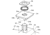
図9,10はそれぞれ、ねじ式ロック機構22の全体構造を示し、図9は、このねじ式ロック機構22をアンロック状態で、また図10は、このねじ式ロック機構22をロック状態でそれぞれ示す。
そして図11,12はそれぞれ、図9,10に示すねじ式ロック機構22の要部を分解して示す斜視図である。
Since the eight screw-
FIGS. 9 and 10 show the overall structure of the screw
11 and 12 are exploded perspective views showing the main part of the screw
図9,10に全体を示すねじ式ロック機構22は、車体フロア5(フロントサイドメンバ7,8)に固着したロックプレート27との共働によりバッテリ2を車体フロア5の下面取り付け位置に着脱自在にロックするもので、
そのためロックプレート27には、矩形開口27aを穿設すると共に、その中央に配して円形開口27bを穿設する。
ロックプレート27を車体フロア5に固着するに際しては、ロックプレート27の四隅における隅角孔27cに挿通したボルトなどの緊締手段により、ロックプレート27を対応する側のフロントサイドメンバ7(8)に取着する。
The screw-
Therefore, the
When fixing the
ねじ式ロック機構22は、バッテリ2(バッテリフレーム2a)に取着したロックベース31と、これに取り付けたボルト32と、これに螺合したロックナット33とを主たる構成要素とする。
ボルト32は、ロックベース31に回転自在に挿通すると共に、図9〜11におけるボルト32の下端に一体成形したボルトヘッド(図示せず)で、図9〜11の上方へ抜け止めする。
The screw
The
上記のごとくロックベース31に抜け止めして回転自在に設けたボルト32は、上記抜け止め端部と反対側の端部にロックナット33を螺合して具える。
このロックナット33は、そのねじ込み方向に見て矩形など四角形断面のナットとし、その中央に、ボルト32へねじ込むための雌ねじを有する構成とする。
As described above, the
The
そして図9〜11に示すように、ロックベース31の中心円形ボス部31aには、ロックナット33の回転を図9に示す弛緩方向制限位置であるアンロック位置、および、図10,11に示す緊締方向制限位置であるロック位置間に制限する2個のストッパ31b,31cを設ける。
As shown in FIGS. 9 to 11, the central
ロックプレート27に設けた矩形孔27aおよび円形孔27bのうち、前者の矩形孔27aは、図9に示すアンロック位置にあるロックナット33の通過を、その通過方向と直交する全方向に正確に位置決めした状態で許容するものとし、後者の円形孔27bは、ロックベース31に設けた中心円形ボス部31aの嵌合を許容するものとする。
ただし円形孔27bの直径は、図10,11に示すロック位置にあるロックナット33の通過を許容しない大きさとする。
Of the
However, the diameter of the
なおロックナット33には、その挿入通過方向先端の長辺側隅角をそれぞれ面取りしてテーパ面33aを、また短辺側隅角をそれぞれ面取りしてテーパ面33bを形成する。
これらテーパ面33a,33bはそれぞれ以下のように機能する。
The
These
つまり、バッテリガイド手段21は前記したごとく、バッテリ2をその上昇ストローク中、横方向に位置決めして、バッテリ収納空所に対し整列させるが、この整列だけでは、コネクタユニット23を構成する車体側コネクタ部材およびバッテリ側コネクタ部材の嵌合部を相互に正しく芯だしすることができない。
かかる芯だし不良があると、両コネクタ部材の相互嵌合部に、嵌合方向を横切る方向の横負荷を掛けてコネクタユニット23の耐久性を低下させるだけでなく、コネクタ部材の相互嵌合部に部分的に隙間を生じさせてスパークが発生する原因となる。
That is, as described above, the battery guide means 21 positions the
If there is such a misalignment, not only will the cross fitting direction of both connector members be subjected to a lateral load across the fitting direction to reduce the durability of the
ところで本実施例においては、ロックナット33をロックプレート27の矩形孔27aに挿入方向へ通過させようとするとき、ロックナット33のテーパ面33a,33bが矩形孔27aの開口縁に衝接して当該矩形孔27aの開口縁との共働により、ロックナット33をロックプレート27の矩形孔27a内に導きつつこの矩形孔27a内に嵌合させる。
このとき、ロックナット33がロックプレート27の矩形孔27a内に隙間無く密に嵌合されることから、バッテリ2を、コネクタユニット23のバッテリ側コネクタ部材が車体側コネクタ部材に対し正確に芯だしされるよう位置決めすることができ、
両コネクタ部材の相互嵌合部に、嵌合方向を横切る方向の横負荷が作用することがなく、コネクタユニット23の耐久性が低下したり、コネクタ部材の相互嵌合部に部分的に隙間が生じてスパークが発生するという問題を回避することができる。
By the way, in this embodiment, when trying to pass the
At this time, since the
There is no lateral load acting in the direction crossing the fitting direction on the mutual fitting portions of both connector members, the durability of the
次に図11,12をも参照しつつ、ボルト32の緊締方向(本実施例では右ねじとする)回転時および弛緩方向回転時に、ロックナット33を同方向へ強制的に連れ回して、図10,11に示す緊締方向制限位置(ロック位置)および図9に示す弛緩方向制限位置(アンロック位置)に回転させるためのロックナット連れ回し機構を詳述する。
Next, referring also to FIGS. 11 and 12, the
図11,12に明示するごとく、ロックナット33をねじ込むボルト32の先端部外周に複数個の軸線方向溝32aを円周方向等間隔に形成することにより、当該ボルト32の先端部を非円形断面形状となす。
かかるボルト32の先端部に図9,10のごとくに嵌着してロックナット強制連れ回し部材34を設ける。
As clearly shown in FIGS. 11 and 12, a plurality of
A lock nut forcibly turning
このロックナット強制連れ回し部材34は、板状部材34aと、これに一体成形した2個の脚部34bとで構成する。
板状部材34aの中心に、ボルト32の上記先端部非円形断面形状に対応する非円形孔34dを穿ち、この非円形孔34dをボルト32の先端部に摺動自在に嵌合することにより、ロックナット強制連れ回し部材34をボルト32の先端部に回転係合させて軸線方向スライド可能に設ける。
The lock nut forcibly rotating
By drilling a
ロックナット強制連れ回し部材34は、ボルト32の先端部に遊嵌したバネ35などの弾性手段でロックナット33に向け附勢し、このため、ロックナット強制連れ回し部材34から遠いバネ35の端部が着座するバネ座36をボルト32の先端部に係着して設ける。
バネ35などの弾性手段でロックナット33に向け附勢されるロックナット強制連れ回し部材34の脚部34bにそれぞれ、ロックナット33の前記した長辺側テーパ面33aとの共働により以下のカム作用を生起する平坦カム面34cを設定する。
The lock nut forcibly rotating
Each of the
ロックナット強制連れ回し部材側平坦カム面34cは、ボルト32の回転時にこれと一体回転するロックナット強制連れ回し部材34が平坦カム面34cをバネ35の弾力でロックナット長辺側テーパ面33aに押圧されることにより、ロックナット33を連れ回し得るよう傾斜させるが、以下の作用も可能になるような傾斜角とする。
つまり、ロックナット33がストッパ31bまたは31cにより対応方向制限位置に抑止された後は、ロックナット強制連れ回し部材34が平坦カム面34cにおいてロックナット長辺側テーパ面33aを乗り越えつつ、また、この乗り越えに伴ってバネ35を圧縮しつつロックナット33から遠ざかる方向へストロークしながら、ロックナット33に対し相対回転してロックナット連れ回し力を解放し得るよう、ロックナット強制連れ回し部材側平坦カム面34cの傾斜角を決定する。
The lock nut forcibly rotating member side
That is, after the
バネ35などの弾性手段でロックナット33に向け附勢されるロックナット強制連れ回し部材34のストローク限界位置は、ボルト32の先端部外周に設けた軸線方向溝32aの長さにより規定する。
軸線方向溝32aの長さを決定するに際しては、ボルト32の緊締方向回転によりロックナット33が図10,11のロック位置にされて緊締方向ストロークを開始した後ただちに、ロックナット強制連れ回し部材34が上記のストローク限界位置となってここに止まり、ロックナット33が更に緊締方向ストロークを行うとき、ロックナット33がロックナット強制連れ回し部材34の脚部34bから離れるよう、軸線方向溝32aの長さを決定する。
The stroke limit position of the lock nut forcibly rotating
When determining the length of the
<ねじ式ロック機構の作用>
上記の構成になるねじ式ロック機構22は、ロックベース31を前記した通りバッテリ2(バッテリフレーム2a)に取着してバッテリ2の側に設け、ロックプレート27を車体フロア5に取着して車体側に設けることにより実用し、
バッテリ2を車体フロア5の下方における下向き開口付きバッテリ収納空所内に着脱自在に収納してロックするに際し、ねじ式ロック機構22はロックプレート27との共働により以下のように当該ロック機能を果たす。
<Operation of screw type locking mechanism>
The screw-
When the
先ず、バッテリ取り付け時のロック作用を図13〜15に基づき説明する。
バッテリ2の取り付けに際しては、ボルト32の図13(a)に矢印で示す弛緩方向への回転によりロックナット33が、後で詳述するようにロックナット連れ回し部材34により連れ回されて、ストッパ31bにより図9および図13(a)に示す弛緩方向制限位置(アンロック位置)されている。
First, the locking action when the battery is attached will be described with reference to FIGS.
When the
ここでバッテリ2を車体フロア5の下面における下向き開口付きバッテリ収納空所内に上昇させると、ロックナット33がテーパ面33a,33bとロックプレート矩形孔27aとの前記した共働により、ロックプレート矩形孔27aに対し芯だしされつつ、図9および図13(a)に示すごとくロックプレート矩形孔27aに通過すると共に、ロックベース31の中心円形ボス部31aがロックプレート円形孔27bに陥入して、ロックナット33がバッテリ収納空所内に位置し、ロックベース31がロックプレート27の外部露出下面に着座する。
Here, when the
この状態でボルト32をナットランナなどにより図13(b)に矢印で示す緊締方向に回転させると、ボルト32と共に回転するロックナット強制連れ回し部材34が平坦カム面34cおよびテーパ面33aを介してロックナット33を連れ回し、このロックナット33をストッパ31cとの衝接により、図10、図13(b)および図14(a)に示す緊締方向制限位置(ロック位置)となす。
しかし、ロックナット33はこの緊締方向制限位置(ロック位置)を越えてロックナット強制連れ回し部材34により連れ回されることがなく、図10、図13(b)および図14(a)に示すごとく当該回転位置に止まる。
In this state, when the
However, the
ところでロックナット強制連れ回し部材34は、図15(a)の状態から同図(b)に示すように、平坦カム面34cにおいてバネ35に抗しロックナット長辺側テーパ面33aを乗り越えつつ、また、この乗り越えに伴ってバネ35を圧縮しつつロックナット33から遠ざかる方向にストロークしながら、ロックナット33に対し相対回転し得てロックナット連れ回し力を解放することができる。
By the way, as shown in FIG. 15 (b) from the state of FIG. 15 (a), the lock nut forcibly turning
このため、ロックナット強制連れ回し部材34の存在によってもボルト32は緊締方向への更なる回転を妨げられない。
ボルト32を更に緊締方向へ回転をさせると、ロックナット33は図14(b)に示すごとく、緊締方向制限位置(ロック位置)を保って同図の矢印方向へねじ込まれ、同図に示す下限位置のロックナット強制連れ回し部材34(脚部34b)から離れつつ、ロックベース31に接近する方向へストロークする。
これによりロックナット33およびロックベース31は、両者間にロックプレート27を挟圧し、バッテリ2をバッテリ収納空所内に収納した位置にロックして保持することができる。
For this reason, the
When the
As a result, the
次に、バッテリ取り外し時のアンロック作用を図16〜18に基づき説明する。
バッテリ2をバッテリ収納空所から取り出すためロック解除するに際しては、上記したロック状態においてボルト32をナットランナなどで図16(a)に矢印で示す弛緩方向へ回転させる。
Next, the unlocking action when removing the battery will be described with reference to FIGS.
When unlocking to take out the
当初はロックナット33が図16(a)に示すように、図14(b)と同じロック用ねじ込みストローク位置にあって、下限位置のロックナット強制連れ回し部材34(脚部34b)から離れているため、ボルト32と共に弛緩方向に回転されるロックナット強制連れ回し部材34は、ロックナット33に対し同方向へ相対回転可能であり、ボルト32の上記弛緩方向回転を何ら妨げない。
Initially, as shown in FIG. 16 (a), the
かかるボルト32の弛緩方向回転は、ロックナット33をして図16(b) および図17(b)に矢印で示す緩み方向へストロークさせ、直ちに図18 (a)に示すごとく下限位置のロックナット強制連れ回し部材34(脚部34b)に接触させる。
しかし図18 (a)に示す接触状態では未だ、ロックナット強制連れ回し部材34(脚部34b)がロックナット33のねじ込み方向後端面上に乗っていて、ロックナット連れ回し力を発生し得ないため、ロックナット強制連れ回し部材34(脚部34b)はボルト32と共にロックナット33に対し弛緩方向へ相対回転する。
Such rotation of the
However, in the contact state shown in FIG. 18 (a), the lock nut forced rotation member 34 (
かかる相対回転によりロックナット強制連れ回し部材34は図18(b)に示すごとく、脚部34bの平坦カム面34cがロックナット長辺側テーパ面33aと対向する回転位置となる。
この時バネ35がロックナット強制連れ回し部材34を図18(b)の矢印方向に附勢して、ロックナット強制連れ回し部材34を、その平坦カム面34cがロックナット長辺側テーパ面33aに対向したストローク位置となす。
以上により図16(b) および図17(a)に示すごとく、ロック時と同じ緊締方向制限位置のままのロックナット33と、ロックナット強制連れ回し部材34とは、テーパ面33aおよび平坦カム面34cの共働により回転係合された状態となる。
As a result of such relative rotation, the lock nut forcibly rotating
At this time, the
As described above, as shown in FIGS. 16 (b) and 17 (a), the
この状態でボルト32を更に弛緩方向に回転させると、ボルト32と共に回転するロックナット強制連れ回し部材34が平坦カム面34cおよびテーパ面33aを介してロックナット33を連れ回し、このロックナット33を図17(b)に示すごとくストッパ31bと衝接する弛緩方向制限位置(アンロック位置)まで強制回転させる。
しかし、ロックナット33はこの弛緩方向制限位置(アンロック位置)を越えてロックナット強制連れ回し部材34により連れ回されることがなく、図17(b)に示すごとく当該回転位置に止まる。
When the
However, the
ところでロックナット強制連れ回し部材34は、図18(b)の状態から同図(a)に示すように、平坦カム面34cにおいてバネ35に抗しロックナット長辺側テーパ面33aを乗り越えつつ、また、この乗り越えに伴ってバネ35を圧縮しつつロックナット33から遠ざかる方向へストロークしながら、ロックナット33に対し相対回転し得てロックナット連れ回し力を解放することができる。
By the way, the lock nut forcibly rotating
このため、ロックナット強制連れ回し部材34の存在によってもボルト32は弛緩方向への更なる回転を妨げられない。
ボルト32を弛緩方向へ更に回転をさせると、ロックナット33は図17(b)の弛緩方向制限位置(アンロック位置)を保って同図の矢印方向へ緩みストロークを行い、バネ35を圧縮しつつロックナット強制連れ回し部材34(脚部34b)を同方向へ変位させながら、ロックベース31から遠ざかる方向へストロークする。
For this reason, the
When the
これにより、ロックナット33およびロックベース31によるロックプレート27の挟圧力(ロック)が解除され、ロックナット33をロックプレート27の矩形孔27aに通過させつつ、またロックベース31の中心円形ボス部31aをロックプレート27の円形孔27bから抜きながら、バッテリ2をバッテリ収納空所内から取り外すことができる。
As a result, the clamping pressure (locking) of the
<コネクタユニット>
なお、バッテリ2は車体側電装系との間の電気接続を司るコネクタ構造が不可欠であり、そのため本実施例においては図5につき前述したごとくコネクタユニット23を設ける。
このコネクタユニット23は、図19,20に示すように、車体側電装系に接続された車体側のコネクタ部材41と、バッテリ2に接続されたバッテリ側のコネクタ部材42とで構成する。
<Connector unit>
The
19 and 20, the
ところで本実施例のように、バッテリ2を、前記したロケートピン式バッテリガイド手段21による案内下で図1〜3および図5に示すごとき車体フロア5の下方における取り付け位置まで上昇させ、この位置でバッテリ2を上記したねじ式ロック機構22により車体フロア5の下方におけるバッテリ収納空所内にロックして取り付ける場合、
車体側のコネクタ部材41およびバッテリ側のコネクタ部材42より成るコネクタユニット23は、バッテリ2の上昇ストローク中にバッテリ側コネクタ部材42が車体側コネクタ部材41に電気接続状態に嵌合されるよう構成、配置するのが、バッテリ2の取り付けを自動化する上で大いに有利であり、本実施例においてもコネクタユニット23を、図19,20につき後述するごとく、そのように構成する。
By the way, as in this embodiment, the
The
しかして、コネクタユニット23が、2個一組のバッテリガイド手段21(図5参照)の双方から遠く離れているときは勿論のこと、これらバッテリガイド手段23のうちの一方のみから遠く離れているときも、
前記した車体組み立て誤差の累積により、コネクタユニット23を成すバッテリ側コネクタ部材42と、車体側コネクタ部材41との相対位置ずれが発生して、バッテリ側コネクタ部材42と車体側コネクタ部材41との相互嵌合部に芯ずれを生ずる。
Thus, when the
Due to the accumulation of the vehicle body assembly error described above, a relative positional shift between the battery
かかるバッテリ側コネクタ部材42および車体側コネクタ部材41間の芯ずれは、両コネクタ部材41,42の相互嵌合部に、嵌合方向を横切る方向の横負荷を掛けてコネクタユニット23の耐久性を低下させるだけでなく、コネクタ部材41,42の相互嵌合部に部分的に隙間を生じさせてスパークの発生原因となる。
Such misalignment between the battery
そこで本実施例においては、バッテリ側コネクタ部材42および車体側コネクタ部材41により構成されるコネクタユニット23を図5に示すように、バッテリ2の車幅方向両側に設けたバッテリガイド手段21の双方に対し近い位置、つまり、これらバッテリガイド手段21から等距離の中間位置に配置する。
Therefore, in this embodiment, the
かかる配置のコネクタユニット23は、バッテリガイド手段21の双方に対し近く、車体側コネクタ部材41およびバッテリ側コネクタ部材42の位置が車体組み立て誤差の累積による影響を最小限にされて高精度である。
従ってこれらコネクタ部材41,42の相互嵌合部における芯ずれを殆どなくすことができ、両コネクタ部材41,42の相互嵌合部に、嵌合方向を横切る方向の横負荷が作用することが無く、コネクタユニット23の耐久性が低下したり、コネクタ部材41,42の相互嵌合部に部分的に隙間が生じてスパークが発生するという問題を解消することができる。
The
Therefore, it is possible to eliminate the misalignment at the mutual fitting portions of these
なお上記の趣旨に照らせば、コネクタユニット23は車体フロア5の車幅方向中程に配置することになる。
ところで車体フロア5の車幅方向中程には、車体フロア5の強度確保と、車体側電装系のワイヤハーネス配索用などのため、トンネル部材6が設けられ、車両前後方向に延在する中高形状のトンネル部が設定されている。
そのため本実施例においてはコネクタユニット23を、図5,19,20に示すように車体フロア5の車幅方向中程で車両前後方向に延在する中高形状のトンネル部材6(トンネル部)内に配置する。
In light of the above, the
By the way, in the middle of the
Therefore, in this embodiment, the
この配置に当たっては、図5に明示するごとく車体フロア5のトンネル部材6(トンネル部)と、バッテリ2(バッテリフレーム2a)の前端面とが交差する箇所のトンネル部材6(トンネル部)内にコネクタユニット23を配置するのが良い。
In this arrangement, as clearly shown in FIG. 5, a connector is provided in the tunnel member 6 (tunnel portion) where the tunnel member 6 (tunnel portion) of the
そして図19,20に示すごとく、コネクタユニット23を構成する車体側コネクタ部材41およびバッテリ側コネクタ部材42のうち、車体側コネクタ部材41は上記の箇所において車体フロア5のトンネル部材6(トンネル部)内にブラケット43を介し取り付け、バッテリ側コネクタ部材42は上記の箇所においてバッテリ2(バッテリフレーム2a)の前端面にブラケット44を介し取り付ける。
19 and 20, of the vehicle body
なお、車体側コネクタ部材41およびバッテリ側コネクタ部材42は、バッテリ2の上昇ストローク中に(好ましくは上昇ストローク端で)電気接続状態に相互嵌合されるような取り付け位置とするのは勿論であるが、
ねじ式ロック機構22によるバッテリ2の取り付け後、下側におけるバッテリ側コネクタ部材42がトンネル部材6(トンネル部)から下方へ張り出すことのないよう車体側コネクタ部材41およびバッテリ側コネクタ部材42の取り付けレベルを決定するのが良い。
Of course, the vehicle body
After the
<ガイド手段、ロック機構およびコネクタユニットの相関関係>
バッテリ2を上昇させて車体フロア5の下方に取り付ける際、バッテリガイド手段21による前記バッテリ2の上下方向案内と、ねじ式ロック機構22のロックプレート27およびロックナット33による前記バッテリ2の位置決めおよびロック機能と、コネクタユニット23(コネクタ部材41,42)の電気接続嵌合とは適切なタイミングで行われる必要がある。
<Correlation between guide means, lock mechanism and connector unit>
When the
ちなみに、バッテリガイド手段21によるバッテリ2の上下方向案内が、ねじ式ロック機構22のロックプレート27およびロックナット33によるバッテリ2の位置決めおよびロック機能の開始よりも遅れると、ロックナット33のテーパ面33a,33bを設けられている先端がロックプレート矩形孔27aと干渉する状態であるのに、ロックナット33がロックプレート矩形孔27aに侵入しようとし、上記の干渉によりねじ式ロック機構22がロック不能になり、バッテリ2を車体フロア5の下方におけるバッテリ収納空所にロックして取り付けることができない。
Incidentally, if the vertical guide of the
また、ねじ式ロック機構22のロックプレート27およびロックナット33によるバッテリ2の位置決めおよびロック機能よりも、コネクタユニット23(コネクタ部材41,42)の電気接続嵌合が早期に行われると、ロックプレート27およびロックナット33によるバッテリ2の位置決め(コネクタユニット23のコネクタ部材41,42間における芯だし)が行われる前にコネクタユニット23のコネクタ部材41,42が相互に電気接続嵌合されることとなる。
かかるコネクタ部材41,42間の芯ずれは、これらコネクタ部材41,42の相互嵌合部に、嵌合方向を横切る方向の横負荷を作用させてコネクタユニット23の耐久性を低下させるだけでなく、コネクタ部材41,42の相互嵌合部に部分的に隙間を生じさせてスパークを発生させる。
In addition, when the electrical connection of the connector unit 23 (
Such misalignment between the
そこで本実施例においては、バッテリガイド手段21によるバッテリ2の上下方向案内と、ねじ式ロック機構22のロックプレート27およびロックナット33によるバッテリ2の位置決めおよびロック機能と、コネクタユニット23(コネクタ部材41,42)の電気接続嵌合とが、図21,22につき以下に説明するタイミングで行われるよう構成する。
Therefore, in this embodiment, the
図21(a),(b),(c)はそれぞれ、バッテリ2が上昇によりバッテリ収納空所に到達した時におけるバッテリガイド手段21(ロケートピン25)のレベル、ねじ式ロック機構22のレベル、およびコネクタユニット23(バッテリ側コネクタ部材42)のレベルを示す。
この時、図21(a)に示すようにロケートピン25がロケートスリーブ26への侵入を開始し、バッテリガイド手段21によりバッテリ2が上下方向に案内され始める。
これにより、ロックナット33のテーパ面33a,33bを設けられている先端がロックプレート矩形孔27aと干渉することなく、ロックプレート矩形孔27aに侵入し得る状態でバッテリ2が上昇されることとなり、この干渉でねじ式ロック機構22のロックプレート27およびロックナット33によるバッテリ2の位置決めおよびロック機能が不能になって、バッテリ2を車体フロア5の下方におけるバッテリ収納空所に取り付けることができなくなる事態を回避することができる。
FIGS. 21 (a), (b), and (c) respectively show the level of the battery guide means 21 (locating pin 25), the level of the screw
At this time, as shown in FIG. 21 (a), the locate
Thereby, the
しかしこの時まだ、図21(b)に示すようにロックナット33がロックプレート27に達しておらず、ねじ式ロック機構22のロックプレート27およびロックナット33によるバッテリ2の位置決めおよびロック機能は未だ開始されていない。
また、図21(c)に示すようにバッテリ側コネクタ部材42が車体側コネクタ部材41に達しておらず、コネクタユニット23(コネクタ部材41,42)の電気接続嵌合も未だ開始されていない。
However, at this time, as shown in FIG. 21 (b), the
Further, as shown in FIG. 21 (c), the battery
図22(a),(b),(c)はそれぞれ、バッテリ2がバッテリガイド手段21による案内下で更に上昇し、ねじ式ロック機構22のロックプレート27およびロックナット33によるバッテリ2の位置決め機能が開始された時におけるバッテリガイド手段21(ロケートピン25)のレベル、ねじ式ロック機構22のレベル、およびコネクタユニット23(バッテリ側コネクタ部材42)のレベルを示す。
22 (a), (b), and (c) show the
ねじ式ロック機構22のロックプレート27およびロックナット33によるバッテリ2の位置決め機能は、図22(c)に示すようにコネクタユニット23のバッテリ側コネクタ部材42を車体側コネクタ部材41に対し正確に芯だしさせる。
The positioning function of the
ねじ式ロック機構22のロックプレート27およびロックナット33によるバッテリ2のロック用上昇ストロークでバッテリ側コネクタ部材42が図22(c)に示す位置から更に上昇するとき、バッテリ側コネクタ部材42は車体側コネクタ部材41と電気接続嵌合するが、
上記したバッテリ側コネクタ部材42および車体側コネクタ部材41間の正確な芯だしによれば、これらコネクタ部材41,42の相互嵌合部に、嵌合方向を横切る方向の横負荷が作用するのを確実に回避することができ、かかる横負荷でコネクタユニット23の耐久性が低下されたり、コネクタ部材41,42の相互嵌合部に部分的に隙間が生じてスパークを発生させるなどの問題を解消し得る。
When the battery
According to the accurate centering between the battery
<実施例の効果>
上記した本実施例のコネクタ構造によれば、バッテリ2と車体側電装系とを接続するためのコネクタユニット23を成すバッテリ側コネクタ部材42を、トンネル部材6(車体フロアトンネル部)と交差する箇所においてバッテリ2の車両前後方向前端面に取り付け、
車体側コネクタ部材41を、バッテリ側コネクタ部材42がバッテリ2の上昇ストローク中電気接続状態に嵌合するような位置に配して、トンネル部材6(車体フロアトンネル部)内に取り付けたため、以下の作用効果が奏し得られる。
<Effect of Example>
According to the connector structure of the above-described embodiment, the battery
Since the vehicle body
つまり、かかる車体側コネクタ部材41およびバッテリ側コネクタ部材42の配置によれば、これらコネクタ部材41,42で構成されるコネクタユニット23が、バッテリ2の取り付け状態で、図21,22に示すごとくトンネル部材6(車体フロアトンネル部)内に位置することとなる。
That is, according to the arrangement of the vehicle body
ところで車体フロア5のトンネル部材6(車体フロアトンネル部)が、バッテリ2の車幅方向両側に設けたバッテリガイド手段21から等距離の位置に存在するため、このトンネル部材6(車体フロアトンネル部)内に位置するコネクタユニット23はバッテリガイド手段21間の中間位置に配置されていることになる。
そのためコネクタユニット23は、バッテリ2の車幅方向両側に設けたバッテリガイド手段21の双方に対し近い位置にあって、コネクタユニット23を構成する車体側コネクタ部材41およびバッテリ側コネクタ部材42は、前記した車体組み立て誤差の累積に起因した相対位置ずれを生ずることがない。
By the way, since the tunnel member 6 (vehicle body floor tunnel part) of the
Therefore, the
従って、バッテリ2の取り付け状態で、車体側コネクタ部材41とバッテリ側コネクタ部材42との相互嵌合部に芯ずれを生ずることがなく、
この芯ずれにより、コネクタユニット23が耐久性を損なわれたり、コネクタ部材41,42の相互嵌合部に部分的に隙間が生じてスパークが発生するという問題を解消することができる。
Therefore, in the mounted state of the
Due to this misalignment, it is possible to solve the problem that the durability of the
更に本実施例によれば、車体側コネクタ部材41およびバッテリ側コネクタ部材42よりなるコネクタユニット23を、トンネル部材6(車体フロアトンネル部)内に設置したため、
トンネル部材6(車体フロアトンネル部)内のスペースを有効利用したコネクタユニット23の設置が可能となり、コネクタユニット23が車室スペースを犠牲にしたり、バッテリ容量を犠牲にすることがない。
Furthermore, according to the present embodiment, the
It is possible to install the
また、トンネル部材6(車体フロアトンネル部)が前記したごとく強度確保のために設けることから、それ自身が高強度であり、
このトンネル部材6(車体フロアトンネル部)内にコネクタユニット23の車体側コネクタ部材41を取り付ける本実施例によれば、車体側コネクタ部材41の取り付け位置精度を高く保つことができ、
車体側コネクタ部材41とバッテリ側コネクタ部材42との相互嵌合部における芯ずれを一層確実に回避し得て上記の作用効果を更に確実なものにすることができる。
In addition, since the tunnel member 6 (body floor tunnel portion) is provided for securing strength as described above, the
According to the present embodiment for attaching the vehicle body
The misalignment in the mutual fitting portion between the vehicle body
更に、車体側電装系がトンネル部材6(車体フロアトンネル部)内に配索されることから、この車体側電装系に対するコネクタユニット23(車体側コネクタ部材42)の結線が、何らの付加的な接続線も要することなく簡単に行われ得て容易であり、コスト上および重量的に大いに有利である。 In addition, since the vehicle body side electrical system is routed in the tunnel member 6 (vehicle body floor tunnel part), the connection of the connector unit 23 (vehicle body side connector member 42) to this vehicle body side electrical system is any additional. There is no need for connecting lines and it can be easily performed and is very advantageous in terms of cost and weight.
<その他の実施例>
なお図示の実施例では、左側フロントサイドメンバ7と左側リヤサイドメンバ11との結合部7a、および右側フロントサイドメンバ8と右側リヤサイドメンバ12との結合部8aよりも車両前後方向前方における高強度で組み立て精度の高い車体フロア前側部分におけるロケートホール7b,8bの近くにバッテリガイド手段21を配置すべく、このガイド手段21がバッテリ2(バッテリフレーム2a)の前端部に近い車幅方向両側に設置されている場合のコネクタ構造につき説明したが、これに限られるものではない。
<Other examples>
In the illustrated embodiment, the
つまり、左右の前後サイドメンバ結合部7a, 8aよりも車両前後方向後方における車体フロア後側部分におけるロケートホールの近くにバッテリガイド手段21を配置すべく、このガイド手段21がバッテリ2(バッテリフレーム2a)の後端部に近い車幅方向両側に設置されている場合、
車体フロアトンネル部と、バッテリ2(バッテリフレーム2a)の後端面とが交差する箇所のトンネル部内にコネクタユニット23を配置することで、前記したと同様な作用効果を達成することができる。
That is, in order to place the battery guide means 21 near the locate hole in the rear part of the vehicle body floor at the rear side in the vehicle longitudinal direction with respect to the left and right front and rear side
By arranging the
またコネクタユニット23は必ずしも、車体フロアトンネル部と、バッテリ2(バッテリフレーム2a)の前端面または後端面との交差箇所の車体トンネル部内に配置する必要はなく、車体トンネル部内なら何処に配置してもよい。
但し、コネクタユニット23を車体フロアトンネル部と、バッテリ2(バッテリフレーム2a)の前端面または後端面との交差箇所の車体トンネル部内に配置する方が、コネクタユニット23の取り付けレベルに関する設計の自由度が高くて有利であるのは言うまでもない。
The
However, if the
更に図示例ではバッテリ2が、多数のバッテリシェルを相互に接続して1ユニットに構成したものである場合に付き説明したが、
バッテリ2が、その他バッテリモジュールと称せられるようなものなど、如何なる型式のものである場合も、前記した本発明の着想を適用して同様な作用効果を奏し得ること勿論である。
Further, in the illustrated example, the
Needless to say, the
1 車体
2 バッテリ
2a バッテリフレーム
3L,3R 左右前輪(駆動輪)
4L,4R 左右後輪
5 車体フロア
6 トンネル部材(車体フロアトンネル部)
7,8 左右フロントサイドメンバ
7a,8a 左右の前後サイドメンバ結合部
7b,8b ロケートホール
9,10 左右サイドシル
11,12 左右リヤサイドメンバ
13 フロントフロアパネル
14 リヤフロアパネル
15,16 橋絡部材
21 バッテリガイド手段
22 ねじ式ロック機構
23 コネクタユニット
24 ブラケット
25 ロケートピン本体
26 ロケートスリーブ
27 ロックプレート
27a 矩形開口
27b 円形開口
31 ロックベース
31b,31c ストッパ
32 ボルト
33 ロックナット
33a ロックナット長辺側テーパ面
33b ロックナット短辺側テーパ面
34 ロックナット強制連れ回し部材
34a 板状部材
34b 脚部
34c 平坦カム面
35 バネ
36 バネ座
41 車体側コネクタ部材
42 バッテリ側コネクタ部材
43,44 ブラケット
1 body
2 Battery
2a battery frame
3L, 3R Left and right front wheels (drive wheels)
4L, 4R left and right rear wheels
5 Body floor
6 Tunnel member (body floor tunnel)
7,8 Left and right front side members
7a, 8a Front / rear side member joint
7b, 8b Locate hall
9,10 Left and right side sills
11,12 Left and right rear side members
13 Front floor panel
14 Rear floor panel
15,16 Bridge members
21 Battery guide means
22 Screw type locking mechanism
23 Connector unit
24 Bracket
25 Locate pin body
26 Locate sleeve
27 Lock plate
27a Rectangular opening
27b Circular opening
31 Lock base
31b, 31c stopper
32 volts
33 Lock nut
33a Lock nut long side taper surface
33b Lock nut short side taper surface
34 Lock nut forced rotation member
34a Plate member
34b Leg
34c Flat cam surface
35 Spring
36 Spring seat
41 Car body side connector member
42 Battery side connector
43,44 bracket
Claims (3)
前記バッテリの直線的上昇ストローク中相互に電気接続されるよう、それぞれ車体およびバッテリに固設された車体側コネクタ部材およびバッテリ側コネクタ部材より成るコネクタユニットを具えた電動車両用バッテリのコネクタ構造において、
前記車体側コネクタ部材を前記トンネル部内に車両上下方向下向きに突出するよう取り付け、
前記バッテリ側コネクタ部材を、前記バッテリの直線的上昇ストローク中、前記トンネル部内の車体側コネクタ部材に電気接続状態に嵌合されるよう配置してバッテリに取り付けたことを特徴とする電動車両用バッテリのコネクタ構造。 Vehicle front-rear direction close to a set of locate holes that serve as a reference position for the body frame member when assembling the vehicle body , under the vehicle body floor with a mid-high shape tunnel that extends in the vehicle front-rear direction in the middle of the vehicle width direction An electrically powered vehicle mounted at a front end position or a vehicle front-rear direction rear end position while being linearly raised under vehicle vertical direction guidance by guide means provided on both sides in the vehicle width direction of the battery,
In the battery connector structure for an electric vehicle comprising a connector unit composed of a vehicle body side connector member and a battery side connector member fixed to the vehicle body and the battery, respectively, so as to be electrically connected to each other during the linear ascending stroke of the battery,
The vehicle body side connector member is mounted in the tunnel portion so as to protrude downward in the vehicle vertical direction ,
The battery for an electric vehicle, wherein the battery-side connector member is arranged and attached to the battery so as to be fitted in an electrically connected state to the vehicle body-side connector member in the tunnel portion during a linear ascending stroke of the battery. Connector structure.
前記バッテリ側コネクタ部材を、前記バッテリの車両前後方向前端面に取り付け、
前記車体側コネクタ部材を、前記バッテリ側コネクタ部材が前記バッテリの直線的上昇ストローク中電気接続状態に嵌合するような位置に配して前記トンネル部内に取り付けたことを特徴とする電動車両用バッテリのコネクタ構造。 The battery connector structure for an electric vehicle according to claim 1, wherein the guide means is provided on both sides in the vehicle width direction of the battery in the vehicle front-rear direction front end.
The battery side connector member is attached to the front end surface of the battery in the vehicle front-rear direction.
The battery for an electric vehicle, wherein the vehicle body side connector member is disposed in a position where the battery side connector member is fitted in an electrically connected state during a linear ascending stroke of the battery, and is mounted in the tunnel portion. Connector structure.
前記バッテリ側コネクタ部材を、前記バッテリの車両前後方向後端面に取り付け、
前記車体側コネクタ部材を、前記バッテリ側コネクタ部材が前記バッテリの直線的上昇ストローク中電気接続状態に嵌合するような位置に配して前記トンネル部内に取り付けたことを特徴とする電動車両用バッテリのコネクタ構造。 The battery connector structure for an electric vehicle according to claim 1, wherein the guide means is provided on both sides in the vehicle width direction of the battery near the rear end in the vehicle front-rear direction.
The battery side connector member is attached to the rear end surface of the battery in the vehicle front-rear direction.
The battery for an electric vehicle, wherein the vehicle body side connector member is disposed in a position where the battery side connector member is fitted in an electrically connected state during a linear ascending stroke of the battery, and is mounted in the tunnel portion. Connector structure.
Priority Applications (2)
| Application Number | Priority Date | Filing Date | Title |
|---|---|---|---|
| JP2009287746A JP5532903B2 (en) | 2009-12-18 | 2009-12-18 | Electric vehicle battery connector structure |
| CN2010206807986U CN202006771U (en) | 2009-12-18 | 2010-12-17 | Connector structure for batteries of electric vehicles |
Applications Claiming Priority (1)
| Application Number | Priority Date | Filing Date | Title |
|---|---|---|---|
| JP2009287746A JP5532903B2 (en) | 2009-12-18 | 2009-12-18 | Electric vehicle battery connector structure |
Publications (2)
| Publication Number | Publication Date |
|---|---|
| JP2011129411A JP2011129411A (en) | 2011-06-30 |
| JP5532903B2 true JP5532903B2 (en) | 2014-06-25 |
Family
ID=44291782
Family Applications (1)
| Application Number | Title | Priority Date | Filing Date |
|---|---|---|---|
| JP2009287746A Expired - Fee Related JP5532903B2 (en) | 2009-12-18 | 2009-12-18 | Electric vehicle battery connector structure |
Country Status (2)
| Country | Link |
|---|---|
| JP (1) | JP5532903B2 (en) |
| CN (1) | CN202006771U (en) |
Families Citing this family (8)
| Publication number | Priority date | Publication date | Assignee | Title |
|---|---|---|---|---|
| JP6036667B2 (en) * | 2013-12-04 | 2016-11-30 | 株式会社豊田自動織機 | Battery unit holding device for vehicle |
| TWI548164B (en) * | 2014-02-24 | 2016-09-01 | 光陽工業股份有限公司 | Battery connecting assembly for vehicle |
| JP6245518B2 (en) * | 2014-02-27 | 2017-12-13 | 三菱自動車工業株式会社 | Electric connector mounting structure for battery pack for electric vehicle |
| JP6771895B2 (en) * | 2015-02-02 | 2020-10-21 | シャープ株式会社 | Autonomous driving device |
| CN105470717A (en) * | 2015-12-31 | 2016-04-06 | 江苏西比亚新能源科技有限公司 | Battery connector for electric vehicle |
| SG11202006165SA (en) * | 2017-12-29 | 2020-07-29 | Shanghai Dianba New Energy Technology Co Ltd | Battery holder, power transfer device, electric vehicle and installation method for electric vehicle |
| CN216672012U (en) * | 2020-09-17 | 2022-06-03 | 奥动新能源汽车科技有限公司 | Battery end electric connector with stable output, battery pack and electric automobile |
| CN113972431B (en) * | 2021-10-25 | 2023-05-02 | 重庆交通职业学院 | Battery fixing device for new energy automobile |
Family Cites Families (3)
| Publication number | Priority date | Publication date | Assignee | Title |
|---|---|---|---|---|
| JPS5952562U (en) * | 1982-09-29 | 1984-04-06 | 株式会社豊田自動織機製作所 | Battery storage device |
| JP3881317B2 (en) * | 2003-01-30 | 2007-02-14 | 川崎重工業株式会社 | Battery box for railway vehicles |
| JP4609006B2 (en) * | 2004-09-06 | 2011-01-12 | 三菱自動車工業株式会社 | Battery pack device for electric vehicles |
-
2009
- 2009-12-18 JP JP2009287746A patent/JP5532903B2/en not_active Expired - Fee Related
-
2010
- 2010-12-17 CN CN2010206807986U patent/CN202006771U/en not_active Expired - Fee Related
Also Published As
| Publication number | Publication date |
|---|---|
| CN202006771U (en) | 2011-10-12 |
| JP2011129411A (en) | 2011-06-30 |
Similar Documents
| Publication | Publication Date | Title |
|---|---|---|
| JP5407835B2 (en) | Battery mounting structure for electric vehicles | |
| JP5532903B2 (en) | Electric vehicle battery connector structure | |
| JP5493820B2 (en) | Electric vehicle battery connector structure | |
| JP5418200B2 (en) | Battery mounting structure for electric vehicles | |
| TWI535584B (en) | Power supply device for electric vehicle | |
| TWI507323B (en) | Power supply device for electric vehicle | |
| CN103282238B (en) | Fixed system | |
| US10207629B2 (en) | Method for mounting a front-end module and a front headlamp on a body of a passenger car and holding arrangement for holding a front headlamp on a front-end module | |
| KR20130041259A (en) | Motor vehicle chassis | |
| US10434968B2 (en) | Connector component for securing an airbag module to a steering wheel, positioning sleeve for the connector component, set comprising such a connector component and a positioning sleeve, steering wheel, airbag module, steering wheel assembly, and method for producing same | |
| CA2549959C (en) | Under-cover mounting structure for an industrial vehicle | |
| US20200189422A1 (en) | Seat track mechanism for vehicle | |
| KR20180069503A (en) | Apparatus and method for assembling composite material leaf spring module | |
| JP2011129412A (en) | Connector structure of battery for electric vehicle | |
| US9358864B2 (en) | Device for fastening a battery module to a bodyshell of a motor vehicle | |
| KR101795067B1 (en) | Battery tray for vehicle | |
| US11351851B2 (en) | Fastening apparatus for fastening a high-voltage storage housing to a bodyshell component of a motor vehicle, and high-voltage storage housing | |
| JP2008502857A (en) | Auto parts mounting device | |
| KR101698742B1 (en) | Seat structure - chamfered mounting of compensating floor latches | |
| US20090195029A1 (en) | Installation support of a loading floor of a passenger car | |
| CN220391399U (en) | Motorcycle | |
| KR100852981B1 (en) | Device for fixing parking cable of vehicle | |
| JP4482496B2 (en) | Seat fastening structure | |
| CN110481457B (en) | Mounting structure of interior trim part for vehicle | |
| JP7224193B2 (en) | Battery structure fixing structure |
Legal Events
| Date | Code | Title | Description |
|---|---|---|---|
| A621 | Written request for application examination |
Free format text: JAPANESE INTERMEDIATE CODE: A621 Effective date: 20121024 |
|
| A977 | Report on retrieval |
Free format text: JAPANESE INTERMEDIATE CODE: A971007 Effective date: 20131115 |
|
| A131 | Notification of reasons for refusal |
Free format text: JAPANESE INTERMEDIATE CODE: A131 Effective date: 20131119 |
|
| A521 | Written amendment |
Free format text: JAPANESE INTERMEDIATE CODE: A523 Effective date: 20140109 |
|
| TRDD | Decision of grant or rejection written | ||
| A01 | Written decision to grant a patent or to grant a registration (utility model) |
Free format text: JAPANESE INTERMEDIATE CODE: A01 Effective date: 20140401 |
|
| A61 | First payment of annual fees (during grant procedure) |
Free format text: JAPANESE INTERMEDIATE CODE: A61 Effective date: 20140414 |
|
| LAPS | Cancellation because of no payment of annual fees |