JP7621693B2 - 電動弁 - Google Patents
電動弁 Download PDFInfo
- Publication number
- JP7621693B2 JP7621693B2 JP2024001176A JP2024001176A JP7621693B2 JP 7621693 B2 JP7621693 B2 JP 7621693B2 JP 2024001176 A JP2024001176 A JP 2024001176A JP 2024001176 A JP2024001176 A JP 2024001176A JP 7621693 B2 JP7621693 B2 JP 7621693B2
- Authority
- JP
- Japan
- Prior art keywords
- valve
- hole
- central axis
- motor
- valve seat
- Prior art date
- Legal status (The legal status is an assumption and is not a legal conclusion. Google has not performed a legal analysis and makes no representation as to the accuracy of the status listed.)
- Active
Links
- 239000003507 refrigerant Substances 0.000 description 76
- 238000004891 communication Methods 0.000 description 11
- 238000005192 partition Methods 0.000 description 9
- 230000000694 effects Effects 0.000 description 6
- 238000005219 brazing Methods 0.000 description 5
- 238000005520 cutting process Methods 0.000 description 5
- 239000000463 material Substances 0.000 description 5
- 238000003825 pressing Methods 0.000 description 5
- 238000011084 recovery Methods 0.000 description 4
- 229910001220 stainless steel Inorganic materials 0.000 description 4
- 239000010935 stainless steel Substances 0.000 description 4
- 239000002184 metal Substances 0.000 description 3
- 230000005514 two-phase flow Effects 0.000 description 3
- 238000002788 crimping Methods 0.000 description 2
- 238000010586 diagram Methods 0.000 description 2
- 239000007788 liquid Substances 0.000 description 2
- 230000014759 maintenance of location Effects 0.000 description 2
- 230000004048 modification Effects 0.000 description 2
- 238000012986 modification Methods 0.000 description 2
- 238000005057 refrigeration Methods 0.000 description 2
- 239000011347 resin Substances 0.000 description 2
- 229920005989 resin Polymers 0.000 description 2
- 238000003466 welding Methods 0.000 description 2
- 229910001369 Brass Inorganic materials 0.000 description 1
- 230000001154 acute effect Effects 0.000 description 1
- 230000004323 axial length Effects 0.000 description 1
- 239000010951 brass Substances 0.000 description 1
- 230000006835 compression Effects 0.000 description 1
- 238000007906 compression Methods 0.000 description 1
- 239000012530 fluid Substances 0.000 description 1
- 239000006260 foam Substances 0.000 description 1
- 230000002093 peripheral effect Effects 0.000 description 1
- 238000003672 processing method Methods 0.000 description 1
- 239000007787 solid Substances 0.000 description 1
Images


Classifications
-
- F—MECHANICAL ENGINEERING; LIGHTING; HEATING; WEAPONS; BLASTING
- F16—ENGINEERING ELEMENTS AND UNITS; GENERAL MEASURES FOR PRODUCING AND MAINTAINING EFFECTIVE FUNCTIONING OF MACHINES OR INSTALLATIONS; THERMAL INSULATION IN GENERAL
- F16K—VALVES; TAPS; COCKS; ACTUATING-FLOATS; DEVICES FOR VENTING OR AERATING
- F16K1/00—Lift valves or globe valves, i.e. cut-off apparatus with closure members having at least a component of their opening and closing motion perpendicular to the closing faces
- F16K1/02—Lift valves or globe valves, i.e. cut-off apparatus with closure members having at least a component of their opening and closing motion perpendicular to the closing faces with screw-spindle
-
- F—MECHANICAL ENGINEERING; LIGHTING; HEATING; WEAPONS; BLASTING
- F16—ENGINEERING ELEMENTS AND UNITS; GENERAL MEASURES FOR PRODUCING AND MAINTAINING EFFECTIVE FUNCTIONING OF MACHINES OR INSTALLATIONS; THERMAL INSULATION IN GENERAL
- F16K—VALVES; TAPS; COCKS; ACTUATING-FLOATS; DEVICES FOR VENTING OR AERATING
- F16K1/00—Lift valves or globe valves, i.e. cut-off apparatus with closure members having at least a component of their opening and closing motion perpendicular to the closing faces
- F16K1/32—Details
- F16K1/34—Cutting-off parts, e.g. valve members, seats
- F16K1/36—Valve members
- F16K1/38—Valve members of conical shape
- F16K1/385—Valve members of conical shape contacting in the closed position, over a substantial axial length, a seat surface having the same inclination
-
- F—MECHANICAL ENGINEERING; LIGHTING; HEATING; WEAPONS; BLASTING
- F16—ENGINEERING ELEMENTS AND UNITS; GENERAL MEASURES FOR PRODUCING AND MAINTAINING EFFECTIVE FUNCTIONING OF MACHINES OR INSTALLATIONS; THERMAL INSULATION IN GENERAL
- F16K—VALVES; TAPS; COCKS; ACTUATING-FLOATS; DEVICES FOR VENTING OR AERATING
- F16K27/00—Construction of housing; Use of materials therefor
- F16K27/02—Construction of housing; Use of materials therefor of lift valves
- F16K27/0254—Construction of housing; Use of materials therefor of lift valves with conical shaped valve members
-
- F—MECHANICAL ENGINEERING; LIGHTING; HEATING; WEAPONS; BLASTING
- F16—ENGINEERING ELEMENTS AND UNITS; GENERAL MEASURES FOR PRODUCING AND MAINTAINING EFFECTIVE FUNCTIONING OF MACHINES OR INSTALLATIONS; THERMAL INSULATION IN GENERAL
- F16K—VALVES; TAPS; COCKS; ACTUATING-FLOATS; DEVICES FOR VENTING OR AERATING
- F16K31/00—Actuating devices; Operating means; Releasing devices
- F16K31/02—Actuating devices; Operating means; Releasing devices electric; magnetic
- F16K31/04—Actuating devices; Operating means; Releasing devices electric; magnetic using a motor
- F16K31/047—Actuating devices; Operating means; Releasing devices electric; magnetic using a motor characterised by mechanical means between the motor and the valve, e.g. lost motion means reducing backlash, clutches, brakes or return means
-
- F—MECHANICAL ENGINEERING; LIGHTING; HEATING; WEAPONS; BLASTING
- F16—ENGINEERING ELEMENTS AND UNITS; GENERAL MEASURES FOR PRODUCING AND MAINTAINING EFFECTIVE FUNCTIONING OF MACHINES OR INSTALLATIONS; THERMAL INSULATION IN GENERAL
- F16K—VALVES; TAPS; COCKS; ACTUATING-FLOATS; DEVICES FOR VENTING OR AERATING
- F16K31/00—Actuating devices; Operating means; Releasing devices
- F16K31/44—Mechanical actuating means
- F16K31/50—Mechanical actuating means with screw-spindle or internally threaded actuating means
-
- F—MECHANICAL ENGINEERING; LIGHTING; HEATING; WEAPONS; BLASTING
- F16—ENGINEERING ELEMENTS AND UNITS; GENERAL MEASURES FOR PRODUCING AND MAINTAINING EFFECTIVE FUNCTIONING OF MACHINES OR INSTALLATIONS; THERMAL INSULATION IN GENERAL
- F16K—VALVES; TAPS; COCKS; ACTUATING-FLOATS; DEVICES FOR VENTING OR AERATING
- F16K47/00—Means in valves for absorbing fluid energy
- F16K47/02—Means in valves for absorbing fluid energy for preventing water-hammer or noise
Landscapes
- Engineering & Computer Science (AREA)
- General Engineering & Computer Science (AREA)
- Mechanical Engineering (AREA)
- Electrically Driven Valve-Operating Means (AREA)
- Valve Housings (AREA)
- Details Of Valves (AREA)
Description
弁室を備えた弁本体と、
前記弁本体に取り付けられ、弁座を備えた弁座部材と、
前記弁室内に配置され、前記弁座に接近又は離間する方向に昇降可能な弁体と、を有し、
前記弁座部材は、配管に接続可能であり、前記弁座に隣接するオリフィス部と、前記オリフィス部に繋がる整流孔と、前記オリフィス部の端部に形成された底壁とを備えた電動弁であって、
前記オリフィス部の中央軸線を直交方向から見たときに、前記中央軸線と前記整流孔の中心軸線との交差角θは、θ≧90°を満たし、
前記交差角θは、前記中央軸線と前記整流孔の中心軸線との交点から下方に延在する前記中央軸線と、前記中心軸線とで挟む角であり、
前記整流孔の中心軸線は、前記配管の内壁に交わることを特徴とする。
図1は、本発明の第1の実施形態に係る電動弁1を示す縦断面図である。ここで、電動弁1におけるロータ側を上方といい、ニードル弁側を下方という。また、「オリフィス」とは、開弁時におけるニードル弁と弁座との隙間をいい、隙間が最小となる位置のニードル弁の外径と弁座の内径とで形成される環状面の面積が「オリフィス断面積」である。「オリフィス部」とは、弁座から下流側の部位であって整流孔との境界までの流路をいう。さらに「流路断面積」とは、冷媒が流れる方向に直交する流路の断面積をいう。
電動弁1は、上端が開口した有底円筒状の弁本体10と、弁本体10の上端面に下端部が溶接等により密封接合された有頂円筒状のキャン45と、弁本体10の内側に固定されたガイドステム15と、ガイドステム15の内側に配設された弁軸21と、弁軸21に対し一体的に回動可能に連結固定されたロータ30と、を備えている。ロータ30の周囲には、ロータ30を回転駆動すべく、キャン45の外周に外嵌されたステータが配設されるが、ここでは図示を省略する。ロータ30とステータとで、ステッピングモータが構成される。電動弁1の軸線をLとする。
電動弁1の動作を、具体的に説明する。
ここで、第二の配管T2から弁室29内に冷媒(流体)が進入しているものとする。
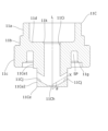
図5は、第2の実施形態に係る電動弁に用いることができる弁座部材11Aの縦断面図である。弁座部材11A以外の電動弁構成については、第1の実施形態と同様であるため、重複説明を省略する。
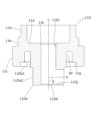
図6は、第3の実施形態に係る電動弁に用いることができる弁座部材11Bの縦断面図である。弁座部材11B以外の電動弁構成については、第1の実施形態と同様であるため、重複説明を省略する。
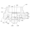
図7は、第4の実施形態に係る電動弁に用いることができる弁座部材11Cの縦断面図である。弁座部材11C以外の電動弁構成については、第1の実施形態と同様であるため、重複説明を省略する。
図8は、第5の実施形態に係る電動弁に用いることができる弁座部材11Dの縦断面図である。弁座部材11D以外の電動弁構成については、第1の実施形態と同様であるため、重複説明を省略する。
図9は、第6の実施形態に係る電動弁に用いることができる弁座部材11Eの縦断面図である。弁座部材11E以外の電動弁構成については、第1の実施形態と同様であるため、重複説明を省略する。
図10は、第7の実施形態に係る電動弁に用いることができる弁座部材11Fの縦断面図である。弁座部材11F以外の電動弁構成については、第1の実施形態と同様であるため、重複説明を省略する。
図11は、第8の実施形態に係る電動弁に用いることができる弁座部材11Gの縦断面図である。弁座部材11G以外の電動弁構成については、第1の実施形態と同様であるため、重複説明を省略する。
図12は、第9の実施形態に係る電動弁に用いることができる弁座部材11Hの縦断面図である。弁座部材11H以外の電動弁構成については、第1の実施形態と同様であるため、重複説明を省略する。
図13は、第10の実施形態に係る電動弁に用いることができる弁座部材11Iの縦断面図である。弁座部材11I以外の電動弁構成については、第1の実施形態と同様であるため、重複説明を省略する。
図14は、第11の実施形態に係る電動弁に用いることができる弁座部材11Kの縦断面図である。弁座部材11K以外の電動弁構成については、第1の実施形態と同様であるため、重複説明を省略する。
図15は、本実施形態の変形例に係る電動弁に用いることができる弁座部材11と多孔質フィルタFTとを組み合わせた構成を示す図であり、左半部が縦断面図であって、右半部が側面図である。多孔質フィルタFT以外の構成については、第1の実施形態と同様であるため、重複説明を省略する。
10 弁本体
11~11K 弁座部材
11e 弁座
15 ガイドステム
21 弁軸
23 弁ホルダ
24 コイルバネ
25 ニードル弁
26 ばね受け部材
27 環状部材
29 弁室
30 ロータ
35 閉弁方向用可動ストッパ
36 開弁方向用可動ストッパ
55 閉弁方向用固定ストッパ
56 開弁方向用固定ストッパ
FT 多孔質フィルタ
Claims (9)
- 弁室を備えた弁本体と、
前記弁本体に取り付けられ、弁座を備えた弁座部材と、
前記弁室内に配置され、前記弁座に接近又は離間する方向に昇降可能な弁体と、を有し、
前記弁座部材は、配管に接続可能であり、前記弁座に隣接するオリフィス部と、前記オリフィス部に繋がる整流孔と、前記オリフィス部の端部に形成された底壁とを備えた電動弁であって、
前記オリフィス部の中央軸線を直交方向から見たときに、前記中央軸線と前記整流孔の中心軸線との交差角θは、θ≧90°を満たし、
前記交差角θは、前記中央軸線と前記整流孔の中心軸線との交点から下方に延在する前記中央軸線と、前記中心軸線とで挟む角であり、
前記整流孔の中心軸線は、前記配管の内壁に交わる、
ことを特徴とする電動弁。 - 前記整流孔は、前記オリフィス部から複数本に分岐する、
ことを特徴とする請求項1に記載の電動弁。 - 前記整流孔の流路断面積の合計は、最大開弁時におけるオリフィス断面積よりも大きい、
ことを特徴とする請求項1または2に記載の電動弁。 - 前記オリフィス部の流路断面積は、最大開弁時におけるオリフィス断面積以上である、
ことを特徴とする請求項3に記載の電動弁。 - 前記整流孔の流路断面積の合計は、前記オリフィス部の流路断面積より大きい、
ことを特徴とする請求項3または4に記載の電動弁。 - 前記整流孔の長さは、前記整流孔の内径より長く、且つ前記オリフィス部の内周半径より長い、
ことを特徴とする請求項1~5のいずれか一項に記載の電動弁。 - 前記弁座部材は、前記オリフィス部を内部に形成するとともに前記配管内に配置される円筒部を備え、
ことを特徴とする請求項1~6のいずれか一項に記載の電動弁。 - 前記オリフィス部の中央軸線を直交方向から見たときに、前記整流孔は、前記オリフィス部に対して鈍角で交差する、
ことを特徴とする請求項1に記載の電動弁。 - 前記オリフィス部の中央軸線を直交方向から見たときに、前記整流孔は、前記オリフィス部に対して直角に交差する、
ことを特徴とする請求項1に記載の電動弁。
Priority Applications (1)
| Application Number | Priority Date | Filing Date | Title |
|---|---|---|---|
| JP2024001176A JP7621693B2 (ja) | 2021-06-10 | 2024-01-09 | 電動弁 |
Applications Claiming Priority (2)
| Application Number | Priority Date | Filing Date | Title |
|---|---|---|---|
| JP2021097288A JP7422409B2 (ja) | 2021-06-10 | 2021-06-10 | 電動弁 |
| JP2024001176A JP7621693B2 (ja) | 2021-06-10 | 2024-01-09 | 電動弁 |
Related Parent Applications (1)
| Application Number | Title | Priority Date | Filing Date |
|---|---|---|---|
| JP2021097288A Division JP7422409B2 (ja) | 2021-06-10 | 2021-06-10 | 電動弁 |
Publications (2)
| Publication Number | Publication Date |
|---|---|
| JP2024038287A JP2024038287A (ja) | 2024-03-19 |
| JP7621693B2 true JP7621693B2 (ja) | 2025-01-27 |
Family
ID=84364450
Family Applications (2)
| Application Number | Title | Priority Date | Filing Date |
|---|---|---|---|
| JP2021097288A Active JP7422409B2 (ja) | 2021-06-10 | 2021-06-10 | 電動弁 |
| JP2024001176A Active JP7621693B2 (ja) | 2021-06-10 | 2024-01-09 | 電動弁 |
Family Applications Before (1)
| Application Number | Title | Priority Date | Filing Date |
|---|---|---|---|
| JP2021097288A Active JP7422409B2 (ja) | 2021-06-10 | 2021-06-10 | 電動弁 |
Country Status (2)
| Country | Link |
|---|---|
| JP (2) | JP7422409B2 (ja) |
| CN (1) | CN115467983A (ja) |
Families Citing this family (1)
| Publication number | Priority date | Publication date | Assignee | Title |
|---|---|---|---|---|
| JP7438549B2 (ja) * | 2021-09-24 | 2024-02-27 | 株式会社不二工機 | 電動弁 |
Citations (3)
| Publication number | Priority date | Publication date | Assignee | Title |
|---|---|---|---|---|
| WO2014061104A1 (ja) | 2012-10-16 | 2014-04-24 | 三菱電機株式会社 | 絞り装置、および冷凍サイクル装置 |
| JP2017089864A (ja) | 2015-11-17 | 2017-05-25 | 株式会社不二工機 | 流量調整弁 |
| CN106979340A (zh) | 2017-04-21 | 2017-07-25 | 杭州东辰热力辅机有限公司 | 一种新型小流量高压差调节阀 |
Family Cites Families (15)
| Publication number | Priority date | Publication date | Assignee | Title |
|---|---|---|---|---|
| JP2916840B2 (ja) * | 1992-09-29 | 1999-07-05 | 株式会社山武 | アングル弁 |
| JPH094759A (ja) * | 1995-06-21 | 1997-01-07 | Kiyobumi Hioki | 定流量弁 |
| JP2001193713A (ja) | 2000-01-13 | 2001-07-17 | Yamatake Corp | オリフィス板 |
| JP2003004160A (ja) * | 2001-06-25 | 2003-01-08 | Fuji Koki Corp | 電動弁 |
| JP4285156B2 (ja) | 2003-08-27 | 2009-06-24 | ダイキン工業株式会社 | 多段電動膨張弁及び冷凍装置 |
| JP2006266667A (ja) | 2005-02-28 | 2006-10-05 | Daikin Ind Ltd | 膨張弁及び冷凍装置 |
| JP4925638B2 (ja) * | 2005-10-14 | 2012-05-09 | 株式会社不二工機 | 電動弁 |
| JP2008232290A (ja) | 2007-03-20 | 2008-10-02 | Saginomiya Seisakusho Inc | ニードル弁及びこのニードル弁を有する冷凍サイクル装置 |
| CN201896952U (zh) * | 2010-06-13 | 2011-07-13 | 无锡智能自控工程有限公司 | 一种防气蚀切割的调节阀 |
| JP5395775B2 (ja) | 2010-10-12 | 2014-01-22 | 株式会社鷺宮製作所 | 電動弁 |
| CN108131479B (zh) * | 2017-12-21 | 2019-05-28 | 绍兴市雅克汽配有限公司 | 一种单向节流阀 |
| JP6966416B2 (ja) | 2018-12-27 | 2021-11-17 | 株式会社鷺宮製作所 | 弁装置および冷凍サイクルシステム |
| JP7179708B2 (ja) | 2019-04-23 | 2022-11-29 | 株式会社鷺宮製作所 | 弁装置および冷凍サイクルシステム |
| WO2022057421A1 (zh) | 2020-09-18 | 2022-03-24 | 广东美的制冷设备有限公司 | 电子膨胀阀、冷媒循环管路及空调器系统 |
| CN112648248B (zh) * | 2020-12-18 | 2023-01-17 | 安徽工业大学 | 一种速控单向阀 |
-
2021
- 2021-06-10 JP JP2021097288A patent/JP7422409B2/ja active Active
-
2022
- 2022-03-16 CN CN202210257888.1A patent/CN115467983A/zh active Pending
-
2024
- 2024-01-09 JP JP2024001176A patent/JP7621693B2/ja active Active
Patent Citations (3)
| Publication number | Priority date | Publication date | Assignee | Title |
|---|---|---|---|---|
| WO2014061104A1 (ja) | 2012-10-16 | 2014-04-24 | 三菱電機株式会社 | 絞り装置、および冷凍サイクル装置 |
| JP2017089864A (ja) | 2015-11-17 | 2017-05-25 | 株式会社不二工機 | 流量調整弁 |
| CN106979340A (zh) | 2017-04-21 | 2017-07-25 | 杭州东辰热力辅机有限公司 | 一种新型小流量高压差调节阀 |
Also Published As
| Publication number | Publication date |
|---|---|
| CN115467983A (zh) | 2022-12-13 |
| JP7422409B2 (ja) | 2024-01-26 |
| JP2024038287A (ja) | 2024-03-19 |
| JP2022188975A (ja) | 2022-12-22 |
Similar Documents
| Publication | Publication Date | Title |
|---|---|---|
| JP7622003B2 (ja) | 電子膨張弁 | |
| RU2302577C2 (ru) | Устройство для снижения давления текучей среды | |
| CN110425331B (zh) | 电动阀 | |
| US10907743B2 (en) | Check valve and reciprocating body for check valve | |
| JP2013234726A (ja) | 電動弁 | |
| JP7621693B2 (ja) | 電動弁 | |
| JP2020034141A (ja) | 電動弁及び冷凍サイクルシステム | |
| JPH10122391A (ja) | 低騒音のボール弁組立体 | |
| JP6659624B2 (ja) | 電動弁及び冷凍サイクルシステム | |
| JP7511716B2 (ja) | 電動弁、および、それを備える冷凍サイクルシステム | |
| JP6359593B2 (ja) | 電動弁 | |
| JP6515164B2 (ja) | 流量制御弁 | |
| JP2013204613A (ja) | 電動弁 | |
| WO2020022214A1 (ja) | 電動弁 | |
| JP2020128782A (ja) | 電動弁、および、それを備える冷凍サイクルシステム | |
| CN110836562A (zh) | 电子膨胀阀及使用该电子膨胀阀的空调系统 | |
| JP2022095807A (ja) | 電動弁及び冷凍サイクルシステム | |
| JP5627188B2 (ja) | 可逆式電動弁 | |
| JP7645575B2 (ja) | 電動弁 | |
| JP2021143759A (ja) | 弁装置 | |
| JP6722230B2 (ja) | 電動弁 | |
| CN113574303A (zh) | 膨胀阀 | |
| JP7511250B2 (ja) | 電動弁 | |
| CN116146761A (zh) | 阀体及电子膨胀阀 | |
| JP7325083B2 (ja) | 膨張弁及びその製造方法 |
Legal Events
| Date | Code | Title | Description |
|---|---|---|---|
| A621 | Written request for application examination |
Free format text: JAPANESE INTERMEDIATE CODE: A621 Effective date: 20240109 |
|
| A977 | Report on retrieval |
Free format text: JAPANESE INTERMEDIATE CODE: A971007 Effective date: 20240813 |
|
| A131 | Notification of reasons for refusal |
Free format text: JAPANESE INTERMEDIATE CODE: A131 Effective date: 20240820 |
|
| A521 | Request for written amendment filed |
Free format text: JAPANESE INTERMEDIATE CODE: A523 Effective date: 20241001 |
|
| TRDD | Decision of grant or rejection written | ||
| A01 | Written decision to grant a patent or to grant a registration (utility model) |
Free format text: JAPANESE INTERMEDIATE CODE: A01 Effective date: 20241210 |
|
| A61 | First payment of annual fees (during grant procedure) |
Free format text: JAPANESE INTERMEDIATE CODE: A61 Effective date: 20250107 |
|
| R150 | Certificate of patent or registration of utility model |
Ref document number: 7621693 Country of ref document: JP Free format text: JAPANESE INTERMEDIATE CODE: R150 |