JP7621693B2 - Motor-operated valve - Google Patents
Motor-operated valve Download PDFInfo
- Publication number
- JP7621693B2 JP7621693B2 JP2024001176A JP2024001176A JP7621693B2 JP 7621693 B2 JP7621693 B2 JP 7621693B2 JP 2024001176 A JP2024001176 A JP 2024001176A JP 2024001176 A JP2024001176 A JP 2024001176A JP 7621693 B2 JP7621693 B2 JP 7621693B2
- Authority
- JP
- Japan
- Prior art keywords
- valve
- hole
- central axis
- motor
- valve seat
- Prior art date
- Legal status (The legal status is an assumption and is not a legal conclusion. Google has not performed a legal analysis and makes no representation as to the accuracy of the status listed.)
- Active
Links
- 239000003507 refrigerant Substances 0.000 description 76
- 238000004891 communication Methods 0.000 description 11
- 238000005192 partition Methods 0.000 description 9
- 230000000694 effects Effects 0.000 description 6
- 238000005219 brazing Methods 0.000 description 5
- 238000005520 cutting process Methods 0.000 description 5
- 239000000463 material Substances 0.000 description 5
- 238000003825 pressing Methods 0.000 description 5
- 238000011084 recovery Methods 0.000 description 4
- 229910001220 stainless steel Inorganic materials 0.000 description 4
- 239000010935 stainless steel Substances 0.000 description 4
- 239000002184 metal Substances 0.000 description 3
- 230000005514 two-phase flow Effects 0.000 description 3
- 238000002788 crimping Methods 0.000 description 2
- 238000010586 diagram Methods 0.000 description 2
- 239000007788 liquid Substances 0.000 description 2
- 230000014759 maintenance of location Effects 0.000 description 2
- 230000004048 modification Effects 0.000 description 2
- 238000012986 modification Methods 0.000 description 2
- 238000005057 refrigeration Methods 0.000 description 2
- 239000011347 resin Substances 0.000 description 2
- 229920005989 resin Polymers 0.000 description 2
- 238000003466 welding Methods 0.000 description 2
- 229910001369 Brass Inorganic materials 0.000 description 1
- 230000001154 acute effect Effects 0.000 description 1
- 230000004323 axial length Effects 0.000 description 1
- 239000010951 brass Substances 0.000 description 1
- 230000006835 compression Effects 0.000 description 1
- 238000007906 compression Methods 0.000 description 1
- 239000012530 fluid Substances 0.000 description 1
- 239000006260 foam Substances 0.000 description 1
- 230000002093 peripheral effect Effects 0.000 description 1
- 238000003672 processing method Methods 0.000 description 1
- 239000007787 solid Substances 0.000 description 1
Images


Classifications
-
- F—MECHANICAL ENGINEERING; LIGHTING; HEATING; WEAPONS; BLASTING
- F16—ENGINEERING ELEMENTS AND UNITS; GENERAL MEASURES FOR PRODUCING AND MAINTAINING EFFECTIVE FUNCTIONING OF MACHINES OR INSTALLATIONS; THERMAL INSULATION IN GENERAL
- F16K—VALVES; TAPS; COCKS; ACTUATING-FLOATS; DEVICES FOR VENTING OR AERATING
- F16K1/00—Lift valves or globe valves, i.e. cut-off apparatus with closure members having at least a component of their opening and closing motion perpendicular to the closing faces
- F16K1/02—Lift valves or globe valves, i.e. cut-off apparatus with closure members having at least a component of their opening and closing motion perpendicular to the closing faces with screw-spindle
-
- F—MECHANICAL ENGINEERING; LIGHTING; HEATING; WEAPONS; BLASTING
- F16—ENGINEERING ELEMENTS AND UNITS; GENERAL MEASURES FOR PRODUCING AND MAINTAINING EFFECTIVE FUNCTIONING OF MACHINES OR INSTALLATIONS; THERMAL INSULATION IN GENERAL
- F16K—VALVES; TAPS; COCKS; ACTUATING-FLOATS; DEVICES FOR VENTING OR AERATING
- F16K1/00—Lift valves or globe valves, i.e. cut-off apparatus with closure members having at least a component of their opening and closing motion perpendicular to the closing faces
- F16K1/32—Details
- F16K1/34—Cutting-off parts, e.g. valve members, seats
- F16K1/36—Valve members
- F16K1/38—Valve members of conical shape
- F16K1/385—Valve members of conical shape contacting in the closed position, over a substantial axial length, a seat surface having the same inclination
-
- F—MECHANICAL ENGINEERING; LIGHTING; HEATING; WEAPONS; BLASTING
- F16—ENGINEERING ELEMENTS AND UNITS; GENERAL MEASURES FOR PRODUCING AND MAINTAINING EFFECTIVE FUNCTIONING OF MACHINES OR INSTALLATIONS; THERMAL INSULATION IN GENERAL
- F16K—VALVES; TAPS; COCKS; ACTUATING-FLOATS; DEVICES FOR VENTING OR AERATING
- F16K27/00—Construction of housing; Use of materials therefor
- F16K27/02—Construction of housing; Use of materials therefor of lift valves
- F16K27/0254—Construction of housing; Use of materials therefor of lift valves with conical shaped valve members
-
- F—MECHANICAL ENGINEERING; LIGHTING; HEATING; WEAPONS; BLASTING
- F16—ENGINEERING ELEMENTS AND UNITS; GENERAL MEASURES FOR PRODUCING AND MAINTAINING EFFECTIVE FUNCTIONING OF MACHINES OR INSTALLATIONS; THERMAL INSULATION IN GENERAL
- F16K—VALVES; TAPS; COCKS; ACTUATING-FLOATS; DEVICES FOR VENTING OR AERATING
- F16K31/00—Actuating devices; Operating means; Releasing devices
- F16K31/02—Actuating devices; Operating means; Releasing devices electric; magnetic
- F16K31/04—Actuating devices; Operating means; Releasing devices electric; magnetic using a motor
- F16K31/047—Actuating devices; Operating means; Releasing devices electric; magnetic using a motor characterised by mechanical means between the motor and the valve, e.g. lost motion means reducing backlash, clutches, brakes or return means
-
- F—MECHANICAL ENGINEERING; LIGHTING; HEATING; WEAPONS; BLASTING
- F16—ENGINEERING ELEMENTS AND UNITS; GENERAL MEASURES FOR PRODUCING AND MAINTAINING EFFECTIVE FUNCTIONING OF MACHINES OR INSTALLATIONS; THERMAL INSULATION IN GENERAL
- F16K—VALVES; TAPS; COCKS; ACTUATING-FLOATS; DEVICES FOR VENTING OR AERATING
- F16K31/00—Actuating devices; Operating means; Releasing devices
- F16K31/44—Mechanical actuating means
- F16K31/50—Mechanical actuating means with screw-spindle or internally threaded actuating means
-
- F—MECHANICAL ENGINEERING; LIGHTING; HEATING; WEAPONS; BLASTING
- F16—ENGINEERING ELEMENTS AND UNITS; GENERAL MEASURES FOR PRODUCING AND MAINTAINING EFFECTIVE FUNCTIONING OF MACHINES OR INSTALLATIONS; THERMAL INSULATION IN GENERAL
- F16K—VALVES; TAPS; COCKS; ACTUATING-FLOATS; DEVICES FOR VENTING OR AERATING
- F16K47/00—Means in valves for absorbing fluid energy
- F16K47/02—Means in valves for absorbing fluid energy for preventing water-hammer or noise
Landscapes
- Engineering & Computer Science (AREA)
- General Engineering & Computer Science (AREA)
- Mechanical Engineering (AREA)
- Electrically Driven Valve-Operating Means (AREA)
- Valve Housings (AREA)
- Details Of Valves (AREA)
Description
本発明は、電動弁に関する。 The present invention relates to a motor-operated valve.
冷凍サイクルにおいて流量制御弁として使用される電動弁は、モータにより回転駆動される弁軸の雄ねじ部を弁本体に設けられた雌ねじ孔に螺合させてなるねじ機構を有し、このねじ機構により回転運動を軸線方向運動に変換することによって、弁軸を軸線方向に変位させ、流量を制御している。 The motor-operated valve used as a flow control valve in the refrigeration cycle has a screw mechanism in which the male thread of the valve shaft, which is driven to rotate by a motor, is screwed into a female threaded hole in the valve body. This screw mechanism converts the rotational motion into axial motion, displacing the valve shaft in the axial direction and controlling the flow rate.
例えば特許文献1には、絞り機能と気泡細分化機能を発揮する多数の小孔を備えた薄板部材(パンチングプレート)を本体に取り付けて、冷媒を通過させる電動弁が開示されている。かかる薄板部材によれば、二相流状態で通過する冷媒の整流機能、絞り機能、二相流状態の冷媒中の気泡を細分化する機能を発揮し、気泡に起因する冷媒通過音を効果的に低減させることができる。
For example,
冷凍サイクルにおいて、冷媒は、一般的には気液二相流状態で配管から電動弁の弁本体に流入するため、本来的に気泡を含んでいる。また、冷媒がオリフィスを通過する際に圧力降下が生じて、一部の冷媒が気化することにより気泡が発生する。このような気泡が破裂する際に騒音を発生することとなる。 In the refrigeration cycle, the refrigerant generally flows from the pipes into the valve body of the motor-operated valve in a gas-liquid two-phase flow state, and so inherently contains air bubbles. In addition, when the refrigerant passes through the orifice, a pressure drop occurs, causing some of the refrigerant to vaporize, generating air bubbles. When these bubbles burst, they generate noise.
特許文献1の電動弁によれば、気泡に起因する冷媒通過音を減少させることができるが、さらなる静穏化の余地がある。
The motor-operated valve in
本発明者らは、特許文献1の電動弁において、オリフィスを通過した冷媒が、圧力回復の過程で薄板部材の小孔を通過し、より大径のパイプ内に進入する際に、乱流が発生して騒音が発生することを見出した。また、特許文献1の電動弁は薄板部材を必要とするため、部品点数が増加し、組み付けに手間がかかるという問題もある。
The inventors discovered that in the motor-operated valve of
そこで本発明は、コストを抑制しつつ、騒音をさらに低減できる電動弁を提供することを目的とする。 Therefore, the present invention aims to provide an electric valve that can further reduce noise while keeping costs down.
上記課題を解決するために、本発明の電動弁は、
弁室を備えた弁本体と、
前記弁本体に取り付けられ、弁座を備えた弁座部材と、
前記弁室内に配置され、前記弁座に接近又は離間する方向に昇降可能な弁体と、を有し、
前記弁座部材は、配管に接続可能であり、前記弁座に隣接するオリフィス部と、前記オリフィス部に繋がる整流孔と、前記オリフィス部の端部に形成された底壁とを備えた電動弁であって、
前記オリフィス部の中央軸線を直交方向から見たときに、前記中央軸線と前記整流孔の中心軸線との交差角θは、θ≧90°を満たし、
前記交差角θは、前記中央軸線と前記整流孔の中心軸線との交点から下方に延在する前記中央軸線と、前記中心軸線とで挟む角であり、
前記整流孔の中心軸線は、前記配管の内壁に交わることを特徴とする。
In order to solve the above problems, the motor-operated valve of the present invention comprises:
A valve body having a valve chamber;
a valve seat member attached to the valve body and having a valve seat;
a valve body that is disposed in the valve chamber and is movable up and down in a direction toward or away from the valve seat,
The valve seat member is connectable to a pipe, and is an electric valve including an orifice portion adjacent to the valve seat, a flow straightening hole connected to the orifice portion, and a bottom wall formed at an end of the orifice portion,
When the central axis of the orifice portion is viewed from a direction perpendicular to the central axis, an intersection angle θ between the central axis and the central axis of the flow straightening hole satisfies θ≧90°,
the intersection angle θ is an angle between the central axis line, which extends downward from an intersection point between the central axis line and the central axis line of the flow straightening hole, and the central axis line,
The central axis of the flow straightening hole intersects with an inner wall of the pipe.
本発明によれば、コストを抑制しつつ、騒音をさらに低減できる電動弁を提供することができる。 The present invention provides an electrically operated valve that can further reduce noise while keeping costs down.
以下、図面を参照して、本発明にかかる実施形態について説明する。 The following describes an embodiment of the present invention with reference to the drawings.
[第1の実施形態]
図1は、本発明の第1の実施形態に係る電動弁1を示す縦断面図である。ここで、電動弁1におけるロータ側を上方といい、ニードル弁側を下方という。また、「オリフィス」とは、開弁時におけるニードル弁と弁座との隙間をいい、隙間が最小となる位置のニードル弁の外径と弁座の内径とで形成される環状面の面積が「オリフィス断面積」である。「オリフィス部」とは、弁座から下流側の部位であって整流孔との境界までの流路をいう。さらに「流路断面積」とは、冷媒が流れる方向に直交する流路の断面積をいう。
[First embodiment]
FIG. 1 is a vertical cross-sectional view showing an
(流量制御弁の構成)
電動弁1は、上端が開口した有底円筒状の弁本体10と、弁本体10の上端面に下端部が溶接等により密封接合された有頂円筒状のキャン45と、弁本体10の内側に固定されたガイドステム15と、ガイドステム15の内側に配設された弁軸21と、弁軸21に対し一体的に回動可能に連結固定されたロータ30と、を備えている。ロータ30の周囲には、ロータ30を回転駆動すべく、キャン45の外周に外嵌されたステータが配設されるが、ここでは図示を省略する。ロータ30とステータとで、ステッピングモータが構成される。電動弁1の軸線をLとする。
(Configuration of Flow Control Valve)
The motor-operated
弁本体10は、中空円筒部10aと底壁部10bとを連設してなる。弁本体10はSUS製の板材をプレス成形することによって形成できるが、SUS素材を圧造することによって形成してもよい。ただし、弁本体10は、SUS(ステンレス)以外の素材(例えば真鍮)を用いることができるし、プレス加工や圧造以外の加工方法(例えば削り出し加工)を用いても形成できる。
The
底壁部10bにおいて、その中央に円形の開口10dが形成されており、開口10dには、弁座部材11がロウ付け等で固定されている。
A
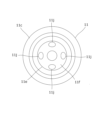
図2は、弁座部材11の縦断面図であり、図3は、弁座部材11を下方向から見た斜視図であり、図4は、弁座部材11の下面図である。
Figure 2 is a vertical cross-sectional view of the
略円筒状の弁座部材11は、上部円筒部11aと、上部円筒部11aより大径の中部円筒部11bと、中部円筒部11bより大径の下部円筒部11cと、中部円筒部11bと下部円筒部11cの境界付近から径方向内方へと延在する隔壁部11dと、隔壁部11dから下方に向かって延在する内側円筒部11eとを連設してなる。内側円筒部11eの下端は、円錐台形部11fを備える。
The approximately cylindrical
中部円筒部11bが開口10dに嵌合し、上部円筒部11aは弁本体10の内部に突出し、下部円筒部11cは弁本体10の外部に配設される。また下部円筒部11cと、内側円筒部11eとの間には、環状空間SPが形成される。下部円筒部11cの下端内周側には、段部11gが形成されている。環状空間SP内に進入させた第一の配管T1(図1)の端部が、内側円筒部11eの外周に嵌挿され、ロウ付けなどにより接続される。段部11gは、配管T1をロウ付けする際に、ロウ材を貯留する部位となる。
The middle
内側円筒部11eの上端から軸線Lに沿って下方に向かい、底壁11hまで延在する円筒孔11iが軸線Lと同軸に形成されている。円筒孔11iの下端外周から斜め外方に延在する整流孔11jが、周方向に分岐して等間隔に4本形成されており、各整流孔11jの外方端は、円錐台形部11fの外周面に位置する。このため整流孔11jは、弁座部材11に組付けた第一の配管T1の内壁を向いており、具体的には整流孔11jの中心軸線Xに沿って整流孔11jの断面を投影したときに、その投影像は第一の配管T1の内壁と重なる。換言すれば、整流孔11jの中心軸線Xは第一の配管T1の内壁と交差する。整流孔11jの中心軸線Xは、軸線Lに対して、0度を超え90度未満の交差角θ(中心軸線Xとの交点から下方に延在する軸線Lと、中心軸線Xとで挟む角とする、以下同じ)で交差する。整流孔11jの数は、2本、3本あるいは5本以上であってもよいが、周方向に等間隔に配置されていると好ましい。円筒孔11iがオリフィス部を構成する。内側円筒部11eの上端内周には、弁座11kが形成されている。なお、中心軸線Xと軸線Lが空間的に交差しない(ねじれの関係となる)ように配置した構造では、側面視(軸線Lの直交方向からの視点)で中心軸線Xと軸線Lの交差する角度を交差角θとする。
A
本実施形態において、整流孔11jの長さは、整流孔11jの内径より長く、また円筒孔11iの内周半径より長い。整流孔11jの長さとは、軸線L及び中心軸線Xを通る面で電動弁1を切断した断面(ここでは図2)において、整流孔11jの内壁が中心軸線Xを挟んだ一対の線分として表され、該内壁の線分の一端同士を結ぶ直線(図2の点線)PL1と、他端同士を結ぶ直線(図2の点線)PL2に、整流孔11jの中心軸線Xが点PT1、PT2で交差したときに、その点PT1、PT2間の距離をいう。
In this embodiment, the length of the
さらに、4本の整流孔11jの流路断面積の合計は、ニードル弁(弁体)25の最大リフト時(最大開弁時)における円錐部25dと弁座11kとの間に形成される流路断面積(すなわちオリフィス断面積)よりも大きい。また、円筒孔11iの流路断面積は、最大開弁時のオリフィス断面積以上である。整流孔11jの流路断面積の合計は、円筒孔11iの流路断面積より大きいと好ましい。
Furthermore, the total flow passage cross-sectional area of the four straightening
図1において、弁本体10の中空円筒部10aには、入口開口10eが形成されており、入口開口10eに第二の配管T2の端部が嵌挿され、ロウ付けなどにより接続されている。入口開口10eの軸線をOとする。
In FIG. 1, an
弁本体10の上端にキャン45の下端が突き当てられた状態で、キャン45の下端内周に鍔状円盤18が嵌合しており、これらは溶接により接合されている。これにより、弁本体10とキャン45とが密閉した状態で一体化される。
With the lower end of the
鍔状円盤18は、複数の貫通孔(不図示)を備えており、この貫通孔を介して、冷媒が弁本体10側とキャン45側との間で移動することは可能になる。
The flange-shaped
ロータ30の内側に配設された樹脂製のガイドステム15は、中実円筒状の本体15aと、中空円筒部15bとを連設してなる。本体15aは、軸線Lに沿って雌ねじ孔15cを有する。またガイドステム15の上方に、閉弁方向用可動ストッパ35を設置している。
The resin guide stem 15 arranged inside the
中空円筒部15bの中間部外周には、弁本体10の上端に溶接された鍔状円盤18が配設されており、この鍔状円盤18を介して、ガイドステム15は弁本体10に対して固定される。中空円筒部15bには、均圧穴15dが形成されている。
A flange-shaped
また、ロータ30及び弁軸21の制御用原点位置を設定すべく、ガイドステム15の本体15aの上面には、断面矩形状の閉弁方向用固定ストッパ55が上向きに突設されており、またガイドステム15の本体15aの下面には、断面矩形状の開弁方向用固定ストッパ56が下向きに突設されている。ここで、ロータ30及び弁軸21の制御用原点位置とは、閉弁方向用可動ストッパ35が閉弁方向用固定ストッパ55に当接して係止され、ロータ30及び弁軸21が最下降位置に達した時の位置のことである。
In order to set the control origin position of the
金属製の弁軸21は、ロータ30に取り付けられた環状の連結体32が外嵌した端部21aと、雌ねじ孔15cに螺合する雄ねじ部21bと、下端近傍に形成された鍔状部21cと、下端連結部21dとを同軸に連設してなる。
The
弁軸21に固定された閉弁方向用可動ストッパ35が、雄ねじ部21bの上端付近に配設され、ロータ30の上壁下面に係止されている。閉弁方向用可動ストッパ35の下面には、断面矩形状のストッパ部35aが形成されている。
The valve closing direction
また、弁軸21の雄ねじ部21bの下端近傍には、鍔状部21cの上面に突き当てるようにして、開弁方向用可動ストッパ36が圧入により嵌合している。開弁方向用可動ストッパ36の上面には、断面矩形状のストッパ部36aが形成されている。ここでは、開弁方向用可動ストッパ36の内周に雌ねじを形成して、雄ねじ部21bと螺合させることにより、開弁方向用可動ストッパ36と弁軸21との固定を行っている。
A valve-opening direction
弁軸21の下方において、弁ホルダ23が、中空円筒部15bの内側に摺動可能に嵌合して配設されている。弁ホルダ23は、中空円筒部23aと、上壁23bとを連設した有頂円筒形状を有している。上壁23bの中央には、段付き開口23cが形成されており、中空円筒部23aは連通穴23dを有する。弁ホルダ23の中空円筒部23aの開放した下端は、閉弁状態で第二の配管T2より下方に配設され、カシメ固定された環状部材27により閉止されている。
Below the
段付き開口23cの段部に弁軸21の鍔状部21cが当接した状態で、下端連結部21dが段付き開口23cを貫通しており、この下端連結部21dを拡径するようにカシメ加工することで、弁軸21と弁ホルダ23とが固定連結されている。弁本体10と弁ホルダ23との間に、弁室29が画成される。
With the
環状部材27を通して弁ホルダ23から突出するようにして、ニードル弁25が配置されている。ニードル弁25は、円柱状の軸部25aと、弁鍔部25bと、弁円筒部25cと、下方に向かうにしたがって縮径する円錐部25dと、複数の円錐形状を段階的に形成した先細部25eとを連設してなる。円錐部25dのテーパ角(軸線Lと交差する角度)は、円錐部25dに接する先細部25eのテーパ角よりも大きい。
The
軸部25aの外周には、リング状部材31が圧入等により嵌合している。リング状部材31の外径は、環状部材27の内径より大きいため、弁ホルダ23からニードル弁25が脱落することが阻止される。リング状部材31と環状部材27との間には、ワッシャ28が配設されており、リング状部材31と環状部材27との相対回転時の摩擦を軽減する。
A ring-shaped
弁ホルダ23の上壁23bと、ニードル弁25との間に、下端鍔部26aを有する円筒状のばね受け部材26が配設されている。さらに上壁23bと下端鍔部26aとの間には、コイルバネ24が配設され、弁ホルダ23に対してばね受け部材26を下方に向かって付勢している。
A cylindrical
円錐部25dが弁座部材11の弁座11kに着座して、上方に向かう反力を受けたときに、ニードル弁25により上向きに付勢されたばね受け部材26が弁ホルダ23の上壁23bの下面(または下端連結部21d)に当接することで、ニードル弁25は弁軸21に対して軸線方向に係止される。
When the
上記した弁軸21、弁ホルダ23、ニードル弁25、及びコイルバネ24は、ニードル弁25が弁座11kから離間している状態(開弁状態)においては、ガイドステム15に対して実質的に一体的に回転しながら昇降する。
When the
(流量制御弁の動作)
電動弁1の動作を、具体的に説明する。
ここで、第二の配管T2から弁室29内に冷媒(流体)が進入しているものとする。
(Flow Control Valve Operation)
The operation of the motor-operated
Here, it is assumed that the refrigerant (fluid) enters the
外部の制御装置から不図示のステータにパルス給電が行われることにより、ロータ30及び弁軸21が一方向に回転駆動され、雌ねじ孔15cと雄ねじ部21bからなるねじ送り機構により、弁軸21及び閉弁方向用可動ストッパ35が回転しながら下降し、ニードル弁25が弁座11kに着座してオリフィスが閉止される。これにより、弁室29から第一の配管T1側へ向かう冷媒の流れを遮断する。
When a pulsed current is supplied from an external control device to a stator (not shown), the
この時点では、可動ストッパ35は未だ固定ストッパ55に当接しておらず、ロータ30及び弁軸21の回転下降は停止されず、コイルバネ24が所定量圧縮されるまでパルス給電が継続される。それにより、ニードル弁25が弁座11kに着座したまま回転が制止される一方、ロータ30、弁軸21、弁ホルダ23等はさらに回転しながら下降する。
At this point, the
このとき、着座したニードル弁25に対して弁軸21及び弁ホルダ23が下降するため、コイルバネ24が縮長圧縮され、これにより弁軸21及び弁ホルダ23の下降力が吸収される。その後、コイルバネ24の圧縮量が所定量となったとき、可動ストッパ35が固定ストッパ55に当接して係止され、ロータ30及び弁軸21が最下降位置に達し、ステータに対しパルス給電が継続されてもロータ30及び弁軸21の下降は強制的に停止される。
At this time, the
このように、ニードル弁25が弁座11kに着座してオリフィス11dが閉止された後においても、可動ストッパ35が固定ストッパ55に当接して係止される制御用原点位置に達するまでは、ロータ30、弁軸21、及び弁ホルダ23の回転下降が継続されることにより、コイルバネ24が圧縮される。そのため、コイルバネ24の付勢力によりニードル弁25が弁座11kに強く押し付けられ、冷媒漏れ等を確実に防止できる。
In this way, even after the
一方、上記制御用原点位置からステータに、逆極性のパルス給電を行うと、ロータ30及び弁軸21が閉弁時とは逆方向に回転駆動され、雌ねじ孔15cと雄ねじ部21bからなるねじ送り機構により、ロータ30、弁軸21、弁ホルダ23及び開弁方向用可動ストッパ36が回転しながら上昇する。これに伴い、ニードル弁25に対する押圧力が弱められ、コイルバネ24が伸張して、ニードル弁25が弁座11kから離れると、オリフィスが開放される。これにより、第二の配管T2から弁室29内へと進入した冷媒は、円錐部25dと弁座11kとの間の隙間を通過して、円筒孔11iを通って第一の配管T1へと流れる。
On the other hand, when a pulse current of reverse polarity is supplied from the control origin position to the stator, the
この場合、ステータへのパルス給電に応じてニードル弁25のリフト量が定まるため、冷媒の流量制御を行える。さらにパルス給電を続けることで、最終的にニードル弁25が全開状態となる。さらにパルス給電が継続された場合、可動ストッパ36が開弁方向用固定ストッパ56に当接して係止され、これにより、ロータ30、弁軸21、及び弁ホルダ23の回転及び上昇が強制的に停止せしめられる。
In this case, the lift amount of the
本実施形態によれば、開弁時に円錐部25dと弁座11kとの間の隙間を通過して、弁座部材11の円筒孔11iに進入した冷媒は、底壁11hに当接して流れの向きを変えられ、円筒状の整流孔11jを介して弁座部材11の外部へと流出する。このとき、冷媒は整流孔11jを通過することで整流効果が発揮されるため、気液二相状態中の気泡及びオリフィス通過時に発生した気泡を微小化して、気泡が破裂した際の騒音を低減できる。また、冷媒が4本の整流孔11jを通過することで、流れの力が分散され、圧力回復が早まり、騒音の原因となる気泡の発生を抑制できる。また、弁座部材11に整流効果を持たせることで、別個に整流部材を設ける必要がなくなり、部品点数が削減される。
According to this embodiment, when the valve is opened, the refrigerant passes through the gap between the
加えて、本実施形態によれば、オリフィス部である円筒孔11iを通過した冷媒を、整流孔11jから第一の配管T1の内壁に衝突させるように流出させているため、冷媒の流速を強制的に低減し、乱流が発生する前に冷媒圧力を回復させることができる。これにより、騒音の原因となる気泡の発生を抑制できる。
In addition, according to this embodiment, the refrigerant that has passed through the
なお、冷媒が第一の配管T1から第二の配管T2に向かって流れる場合、第一の配管T1から弁座部材11内に進入した冷媒は、整流孔11jによって流れの向きを変えられ、ストレートにオリフィスに向かわない。したがって、流速が早い冷媒がオリフィスを通過しないため、開弁時におけるニードル弁25の振動を抑制できる。
When the refrigerant flows from the first pipe T1 to the second pipe T2, the refrigerant that enters the
[第2の実施形態]
図5は、第2の実施形態に係る電動弁に用いることができる弁座部材11Aの縦断面図である。弁座部材11A以外の電動弁構成については、第1の実施形態と同様であるため、重複説明を省略する。
Second Embodiment
5 is a vertical cross-sectional view of a
本実施形態の弁座部材11Aは、図2に示す弁座部材11に対して、底壁11Ahに、円筒孔11Aiの下端となるテーパ状部11Amを形成した点が主として異なる。テーパ状部11Amの一部に、整流孔11Ajが接している。整流孔11Ajの中心軸線Xは第一の配管T1(図1参照)の内壁と交差する。整流孔11Ajの中心軸線Xは、軸線Lに対して、0度を超え90度未満の交差角θで交差する。本実施形態においても、内側円筒部11Aeの下端は、円錐台形部11Afを備える。第1の実施形態と共通する構成については、同じ符号を付して重複説明を省略する。
The
開弁時にオリフィスを通過した冷媒は、オリフィス部である円筒孔11Aiに沿って流れてテーパ状部11Amに至る。冷媒の少なくとも一部はテーパ状部11Amで滞留した後、整流孔11Ajに進入するため、冷媒圧力を回復させやすいという効果がある。また、冷媒がテーパ状部11Amのエッジ部を通過する際に、気泡を分散化する効果もある。なお、テーパ状部11Amは、例えばドリルなどの切削工具を用いて円筒孔11Aiを形成する際に、工具先端形状を転写することで形成できる。 When the valve is open, the refrigerant that passes through the orifice flows along the cylindrical hole 11Ai, which is the orifice portion, and reaches the tapered portion 11Am. At least a portion of the refrigerant remains in the tapered portion 11Am before entering the flow straightening hole 11Aj, which has the effect of making it easier to restore the refrigerant pressure. In addition, when the refrigerant passes through the edge portion of the tapered portion 11Am, it also has the effect of dispersing air bubbles. The tapered portion 11Am can be formed, for example, by transferring the shape of the tip of a cutting tool such as a drill when forming the cylindrical hole 11Ai.
[第3の実施形態]
図6は、第3の実施形態に係る電動弁に用いることができる弁座部材11Bの縦断面図である。弁座部材11B以外の電動弁構成については、第1の実施形態と同様であるため、重複説明を省略する。
[Third embodiment]
6 is a vertical cross-sectional view of a
本実施形態の弁座部材11Bは、図2に示す弁座部材11に対して、各整流孔11Bjの中間位置から、軸線Lに平行に底壁11Bhを貫通して、端部が円錐台形部11fの頂面(下面)に位置する連通開口11Bmを形成した点が主として異なる。連通開口11Bmの内径は、整流孔Bjの内径の1/4以下であると好ましい。整流孔11Bjの中心軸線Xは第一の配管T1(図1参照)の内壁と交差する。整流孔11Bjの中心軸線Xは、軸線Lに対して、0度を超え90度未満の交差角θで交差する。本実施形態においても、内側円筒部11Beの下端は、円錐台形部11Bfを備える。第1の実施形態と共通する構成については、同じ符号を付して重複説明を省略する。
The
開弁時にオリフィスを通過した冷媒は、オリフィス部である円筒孔11Biに沿って流れて底壁11Bhに至る。ここから、冷媒は整流孔11Bjを通過して弁座部材11Bの外部へと流出するが、その際に第一の配管T1の内壁に衝突して渦を形成することがある。かかる渦が冷媒の圧力回復を妨げるおそれがある。
When the valve is open, the refrigerant that passes through the orifice flows along the cylindrical hole 11Bi, which is the orifice portion, and reaches the bottom wall 11Bh. From here, the refrigerant passes through the flow straightening hole 11Bj and flows out of the
これに対し、本実施形態によれば、冷媒が連通開口11Bmの上端を通過する際に連通開口11Bmの内部に負圧が発生するため、連通開口11Bmの下端から冷媒を吸い上げる。これにより、第一の配管T1の内壁に衝突して形成される渦を速やかに消失させることができる。 In contrast, according to the present embodiment, when the refrigerant passes through the upper end of the communication opening 11Bm, negative pressure is generated inside the communication opening 11Bm, so that the refrigerant is sucked up from the lower end of the communication opening 11Bm. This allows the vortex that is formed when the refrigerant collides with the inner wall of the first pipe T1 to quickly disappear.
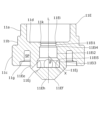
[第4の実施形態]
図7は、第4の実施形態に係る電動弁に用いることができる弁座部材11Cの縦断面図である。弁座部材11C以外の電動弁構成については、第1の実施形態と同様であるため、重複説明を省略する。
[Fourth embodiment]
7 is a vertical cross-sectional view of a
本実施形態の弁座部材11Cは、内側円筒部11Ceおよび整流孔11Cjの形状が主として異なる。第1の実施形態と共通する構成については、同じ符号を付して重複説明を省略する。
The
隔壁部11dから下方に向かって延在する内側円筒部11Ceは、隔壁部11d側の拡径部11Ce1と、拡径部11Ce1より外径が小さい先端側の縮径部11Ce2とからなる。第一の配管T1(図1)は、拡径部11Ce1にのみ嵌合する。
The inner cylindrical portion 11Ce extending downward from the
内側円筒部11Ceの内部に形成された円筒孔11Ciの下端から、複数の整流孔11Cjが弁座11k側に向かって斜めに延在するように形成されている。整流孔11Cjは、弁座部材11Cに組付けた第一の配管T1の内壁を向いている。すなわち整流孔11Cjの中心軸線Xは第一の配管T1(図1参照)の内壁と交差する。整流孔11Cjの中心軸線Xは、軸線Lに対して、90度を超え180度未満の交差角θで交差する。
Multiple straightening holes 11Cj are formed to extend obliquely from the lower end of the cylindrical hole 11Ci formed inside the inner cylindrical portion 11Ce toward the
本実施形態においても、整流孔11Cjの長さ(孔内壁の軸線方向最短長)は、整流孔11Cjの内径より長く、また円筒孔11Ciの内周半径より長い。また、4本の整流孔11Cjの流路断面積の合計は、最大開弁時のオリフィス断面積よりも大きい。また、円筒孔11Ciの流路断面積は、最大開弁時のオリフィス断面積以上である。整流孔11Cjの流路断面積の合計は、円筒孔11Ciの流路断面積より大きいと好ましい。 In this embodiment, too, the length of the flow straightening holes 11Cj (the shortest axial length of the hole inner wall) is longer than the inner diameter of the flow straightening holes 11Cj and longer than the inner radius of the cylindrical holes 11Ci. The total flow path cross-sectional area of the four flow straightening holes 11Cj is larger than the orifice cross-sectional area when the valve is fully open. The flow path cross-sectional area of the cylindrical holes 11Ci is equal to or larger than the orifice cross-sectional area when the valve is fully open. It is preferable that the total flow path cross-sectional area of the flow straightening holes 11Cj is larger than the flow path cross-sectional area of the cylindrical holes 11Ci.
開弁時にオリフィスを通過した冷媒は、オリフィス部である円筒孔11Ciに沿って流れて底壁11Chに至る。ここで、冷媒は流れの方向を鋭角に曲げられ、整流孔11Cjを通過して弁座部材11Cの外部へと流出する。
When the valve is open, the refrigerant that passes through the orifice flows along the cylindrical hole 11Ci, which is the orifice portion, and reaches the bottom wall 11Ch. Here, the flow direction of the refrigerant is bent at an acute angle, passes through the flow straightening hole 11Cj, and flows out of the
第一の配管T1と縮径部11Ce2との間には間隙があるため、縮径部11Ce2から流れ出る冷媒は、第一の配管T1の内壁に当たり、さらに第一の配管T1と縮径部11Ce2との間隙を通過して下方に向かう。このとき、第一の配管T1と縮径部11Ce2との間から流れ出る冷媒の流速は、最大開弁時のオリフィス断面積を通過する冷媒の流速よりも遅くなる。 Because there is a gap between the first pipe T1 and the reduced diameter portion 11Ce2, the refrigerant flowing out of the reduced diameter portion 11Ce2 hits the inner wall of the first pipe T1 and then passes through the gap between the first pipe T1 and the reduced diameter portion 11Ce2 and flows downward. At this time, the flow speed of the refrigerant flowing out from between the first pipe T1 and the reduced diameter portion 11Ce2 is slower than the flow speed of the refrigerant passing through the orifice cross-sectional area when the valve is fully open.
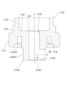
[第5の実施形態]
図8は、第5の実施形態に係る電動弁に用いることができる弁座部材11Dの縦断面図である。弁座部材11D以外の電動弁構成については、第1の実施形態と同様であるため、重複説明を省略する。
[Fifth embodiment]
8 is a vertical cross-sectional view of a
本実施形態の弁座部材11Dは、内側円筒部11Deおよび整流孔11Djの形状が主として異なる。第1の実施形態と共通する構成については、同じ符号を付して重複説明を省略する。
The
隔壁部11dから下方に向かって延在する内側円筒部11Deは、隔壁部11d側の拡径部11De1と、拡径部11De1より外径が小さい先端側の縮径部11De2とからなる。第一の配管T1(図1)は、拡径部11De1にのみ嵌合する。
The inner cylindrical portion 11De extending downward from the
内側円筒部11Deの内部に形成された円筒孔11Diの下端から、整流孔11Djが軸線Lに直交する方向に延在するように形成されており、すなわちオリフィス部である円筒孔11Diに対して整流孔11Djは直角に交差する。整流孔11Djは、弁座部材11Dに組付けた第一の配管T1の内壁を向いている。換言すれば、整流孔11Djの中心軸線Xは第一の配管T1(図1参照)の内壁と交差する。整流孔11Djの中心軸線Xは、軸線Lに対して、90度の交差角θで交差する。
The flow straightening hole 11Dj is formed to extend from the lower end of the cylindrical hole 11Di formed inside the inner cylindrical portion 11De in a direction perpendicular to the axis L, i.e., the flow straightening hole 11Dj intersects at a right angle with the cylindrical hole 11Di, which is the orifice portion. The flow straightening hole 11Dj faces the inner wall of the first piping T1 assembled to the
本実施形態においても、整流孔11Djの長さは、整流孔11Djの内径より長く、また円筒孔11Diの内周半径より長いと好ましい。また、整流孔11Djの流路断面積は、最大開弁時のオリフィス断面積よりも大きい。また、円筒孔11Diの最小流路断面積は、最大開弁時のオリフィス断面積以上である。整流孔11Djの流路断面積は、円筒孔11Diの流路断面積より大きいと好ましい。 In this embodiment, too, it is preferable that the length of the flow straightening hole 11Dj is longer than the inner diameter of the flow straightening hole 11Dj and longer than the inner radius of the cylindrical hole 11Di. In addition, the flow passage cross-sectional area of the flow straightening hole 11Dj is larger than the orifice cross-sectional area when the valve is fully open. In addition, the minimum flow passage cross-sectional area of the cylindrical hole 11Di is equal to or larger than the orifice cross-sectional area when the valve is fully open. It is preferable that the flow passage cross-sectional area of the flow straightening hole 11Dj is larger than the flow passage cross-sectional area of the cylindrical hole 11Di.
開弁時にオリフィスを通過した冷媒は、オリフィス部である円筒孔11Diに沿って流れて底壁11Dhに至る。ここで、冷媒は流れの方向を直角に曲げられ、整流孔11Djを通過して弁座部材11Dの外部へと流出する。
When the valve is open, the refrigerant that passes through the orifice flows along the cylindrical hole 11Di, which is the orifice portion, and reaches the bottom wall 11Dh. Here, the refrigerant's flow direction is bent at a right angle, passes through the flow straightening hole 11Dj, and flows out of the
第一の配管T1と縮径部11De2との間には間隙があるため、縮径部11De2から流れ出る冷媒は、第一の配管T1の内壁に当たり、さらに第一の配管T1と縮径部11De2との間隙を通過して下方に向かう。このとき、第一の配管T1と縮径部11De2の間から流れ出る冷媒の流速は、最大開弁時のオリフィス断面積を通過する冷媒の流速よりも遅くなる。 Because there is a gap between the first pipe T1 and the reduced diameter section 11De2, the refrigerant flowing out of the reduced diameter section 11De2 hits the inner wall of the first pipe T1 and then passes through the gap between the first pipe T1 and the reduced diameter section 11De2 and flows downward. At this time, the flow speed of the refrigerant flowing out from between the first pipe T1 and the reduced diameter section 11De2 is slower than the flow speed of the refrigerant passing through the orifice cross-sectional area when the valve is fully open.
[第6の実施形態]
図9は、第6の実施形態に係る電動弁に用いることができる弁座部材11Eの縦断面図である。弁座部材11E以外の電動弁構成については、第1の実施形態と同様であるため、重複説明を省略する。
Sixth embodiment
9 is a vertical cross-sectional view of a
本実施形態の弁座部材11Eは、円筒孔11Eiの形状が主として異なる。本実施形態においても、整流孔11Ejの中心軸線Xは第一の配管T1(図1参照)の内壁と交差する。整流孔11Ejの中心軸線Xは、軸線Lに対して、0度を超え90度未満の交差角θで交差する。内側円筒部11Eeの下端は、円錐台形部11Efを備える。第1の実施形態と共通する構成については、同じ符号を付して重複説明を省略する。
The
円筒孔11Eiは、弁座11kの下方に配設された第1孔11Ei1と、第1孔11Ei1より大径の第2孔11Ei2と、第2孔11Ei2より大径の第3孔11Ei3とを有する。第1孔11Ei1と第2孔11Ei2とは、第1テーパ部11Ei4により連結され、第2孔11Ei2と第3孔11Ei3とは、第2テーパ部11Ei5により連結されている。第3孔11Ei3(及び第2テーパ部11Ei5)の下端に、4本の整流孔11Ejが連通している。なお、円筒孔11Eiは、例えばシャンク径が刃先外径より小さいエンドミル工具などを用いて加工形成できる。また、第1孔11Ei1の流路断面積は、最大開弁時のオリフィス断面積以上である。整流孔11Ejの流路断面積の合計は、第1孔11Ei1の流路断面積より大きいと好ましい。
The cylindrical hole 11Ei has a first hole 11Ei1 arranged below the
開弁時にオリフィスを通過した冷媒は、第1孔11Ei1と、第1テーパ部11Ei4と、第2孔11Ei2と、第2テーパ部11Ei5と、第3孔11Ei3に沿って流れて底壁11Ehに至る。このときオリフィスから底壁11Ehに至るまでに、流路断面積が三段階で拡大する。これにより冷媒圧力を徐々に回復させることができる。 When the valve is open, the refrigerant that passes through the orifice flows along the first hole 11Ei1, the first tapered portion 11Ei4, the second hole 11Ei2, the second tapered portion 11Ei5, and the third hole 11Ei3 to the bottom wall 11Eh. At this time, the flow path cross-sectional area expands in three stages from the orifice to the bottom wall 11Eh. This allows the refrigerant pressure to gradually recover.
さらに、冷媒は、斜め下方を向いた整流孔11Ejを通過して弁座部材11Eの外部へと流出して、第一の配管T1の内壁に当たることで、冷媒の流速を強制的に低減し、乱流が発生する前に冷媒圧力を回復させることができる。
Furthermore, the refrigerant flows out of the
[第7の実施形態]
図10は、第7の実施形態に係る電動弁に用いることができる弁座部材11Fの縦断面図である。弁座部材11F以外の電動弁構成については、第1の実施形態と同様であるため、重複説明を省略する。
[Seventh embodiment]
10 is a vertical cross-sectional view of a
本実施形態の弁座部材11Fは、円筒孔11Fiの形状が主として異なる。本実施形態においても、整流孔11Fjの中心軸線Xは第一の配管T1(図1参照)の内壁と交差する。整流孔11Fjの中心軸線Xは、軸線Lに対して、0度を超え90度未満の交差角θで交差する。内側円筒部11Feの下端は、円錐台形部11Ffを備える。第1の実施形態と共通する構成については、同じ符号を付して重複説明を省略する。
The
円筒孔11Fiは、弁座11kの下方に配設された第1孔11Fi1と、第1孔11Fi1より大径の第2孔11Fi2とを有する。第1孔11Fi1と第2孔11Fi2とは、テーパ部11Fi3により連結される。第2孔11Fi2の下端に、4本の整流孔11Fjが連通している。なお、円筒孔11Fiは、例えばシャンク径が刃先外径より小さいエンドミル工具などを用いて加工形成できる。また、第1孔11Fi1の流路断面積は、最大開弁時のオリフィス断面積以上である。整流孔11Fjの流路断面積の合計は、第1孔11Fi1の流路断面積より大きいと好ましい。
The cylindrical hole 11Fi has a first hole 11Fi1 arranged below the
開弁時にオリフィスを通過した冷媒は、第1孔11Fi1と、テーパ部11Fi3と、第2孔11Fi2に沿って流れて底壁11Fhに至る。このときオリフィスから底壁11Fhに至るまでに、流路断面積が二段階で拡大する。これにより冷媒圧力を徐々に回復させることができる。 When the valve is open, the refrigerant that passes through the orifice flows along the first hole 11Fi1, the tapered portion 11Fi3, and the second hole 11Fi2 to reach the bottom wall 11Fh. At this time, the flow path cross-sectional area expands in two stages from the orifice to the bottom wall 11Fh. This allows the refrigerant pressure to gradually recover.
さらに、冷媒は、斜め下方を向いた整流孔11Fjを通過して弁座部材11Fの外部へと流出して、第一の配管T1の内壁に当たることで、冷媒の流速を強制的に低減し、乱流が発生する前に冷媒圧力を回復させることができる。
Furthermore, the refrigerant flows out of the
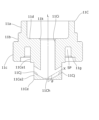
[第8の実施形態]
図11は、第8の実施形態に係る電動弁に用いることができる弁座部材11Gの縦断面図である。弁座部材11G以外の電動弁構成については、第1の実施形態と同様であるため、重複説明を省略する。
Eighth embodiment
11 is a vertical cross-sectional view of a
本実施形態の弁座部材11Gは、円筒孔11Giにつながる中央孔11Gnを底壁11Ghに形成した点が主として異なる。本実施形態においても、整流孔11Gjの中心軸線Xは第一の配管T1(図1参照)の内壁と交差する。整流孔11Gjの中心軸線Xは、軸線Lに対して、0度を超え90度未満の交差角θで交差する。内側円筒部11Geの下端は、円錐台形部11Gfを備える。第1の実施形態と共通する構成については、同じ符号を付して重複説明を省略する。
The
中央孔11Gnは、円筒孔11Giと同軸であり、円筒孔11Gi及び整流孔11Gjの内径よりも小さい内径を有する。円筒孔11Giと整流孔11Gjとは、端部同士が接していてもよいし、互いに離間していてもよい。 The central hole 11Gn is coaxial with the cylindrical hole 11Gi and has an inner diameter smaller than the inner diameters of the cylindrical hole 11Gi and the flow straightening hole 11Gj. The ends of the cylindrical hole 11Gi and the flow straightening hole 11Gj may be in contact with each other or may be spaced apart from each other.
開弁時にオリフィスを通過した冷媒は、オリフィス部である円筒孔11Giに沿って流れて底壁11Ghに至る。ここで、冷媒の一部は、整流孔11Gjを通過して弁座部材11Gの外部へと流出し、第一の配管T1に衝突するが、このとき渦が形成される場合がある。一方、底壁11Ghに到達した冷媒の残りは、ストレートに中央孔11Gnを通過して、弁座部材11Gの外部へと流出するが、それにより第一の配管T1の内壁に形成された渦を消失させる効果がある。これにより速やかな冷媒の圧力回復を図ることができる。
When the valve is open, the refrigerant that passes through the orifice flows along the cylindrical hole 11Gi, which is the orifice portion, and reaches the bottom wall 11Gh. Here, part of the refrigerant passes through the straightening hole 11Gj and flows out of the
[第9の実施形態]
図12は、第9の実施形態に係る電動弁に用いることができる弁座部材11Hの縦断面図である。弁座部材11H以外の電動弁構成については、第1の実施形態と同様であるため、重複説明を省略する。
[Ninth embodiment]
12 is a vertical cross-sectional view of a
図12を参照して、整流孔11Hjの長さは、軸線L及び中心軸線Xを通る面で電動弁1を切断した断面(ここでは図12)において、整流孔11Hjの内壁が中心軸線Xを挟んだ一対の線分として表され、該内壁の線分の一端同士を結ぶ直線(図12の点線)PL1と、他端同士を結ぶ直線(図12の点線)PL2に、整流孔11Hjの中心軸線Xが点PT1、PT2で交差したときに、その点PT1、PT2間の距離である。本実施形態においても、整流孔11Hjの中心軸線Xは第一の配管T1(図1参照)の内壁と交差する。整流孔11Hjの中心軸線Xは、軸線Lに対して、0度を超え90度未満の交差角θで交差する。内側円筒部11Heの下端は、円錐台形部11Hfを備える。
With reference to FIG. 12, the length of the flow straightening hole 11Hj is the distance between points PT1 and PT2 when the inner wall of the flow straightening hole 11Hj is represented as a pair of line segments sandwiching the central axis X in a cross section (here, FIG. 12) of the motor-operated
本実施形態の弁座部材11Hは、円筒孔11Hiの形状、および円筒孔11Hiにつながる中央孔11Hnを底壁11Hhに形成した点が主として異なる。第1の実施形態と共通する構成については、同じ符号を付して重複説明を省略する。
The
円筒孔11Hiは、弁座11kの下方に配設された第1孔11Hi1と、第1孔11Hi1より大径の第2孔11Hi2とを有する。第1孔11Hi1と第2孔11Hi2とは、テーパ部11Hi3により連結される。第2孔11Hi2の下端に、4本の整流孔11Hjが連通している。なお、円筒孔11Hiは、例えばシャンク径が刃先外径より小さいエンドミル工具などを用いて加工形成できる。また、第1孔11Hi1の流路断面積は、最大開弁時のオリフィス断面積以上である。整流孔11Hjの流路断面積の合計は、第1孔11Hi1の流路断面積より大きいと好ましい。
The cylindrical hole 11Hi has a first hole 11Hi1 arranged below the
中央孔11Hnは、円筒孔11Hiと同軸であり、円筒孔11Hi及び整流孔11Hjの内径よりも小さい内径を有する。 The central hole 11Hn is coaxial with the cylindrical hole 11Hi and has an inner diameter smaller than the inner diameters of the cylindrical hole 11Hi and the flow straightening hole 11Hj.
開弁時にオリフィスを通過した冷媒は、第1孔11Hi1と、テーパ部11Hi3と、第2孔11Hi2に沿って流れて底壁11Hhに至る。このときオリフィスから底壁11Hhに至るまでに、流路断面積が二段階で拡大する。これにより冷媒圧力を徐々に回復させることができる。 When the valve is open, the refrigerant that passes through the orifice flows along the first hole 11Hi1, the tapered portion 11Hi3, and the second hole 11Hi2 to reach the bottom wall 11Hh. At this time, the flow path cross-sectional area expands in two stages from the orifice to the bottom wall 11Hh. This allows the refrigerant pressure to gradually recover.
底壁11Hhに到達した冷媒の一部は、整流孔11Hjを通過して弁座部材11Hの外部へと流出し、第一の配管T1に衝突するが、このとき渦が形成される場合がある。一方、底壁11Hhに到達した冷媒の残りは、ストレートに中央孔11Hnを通過して、弁座部材11Hの外部へと流出するが、それにより第一の配管T1の内壁に形成された渦を消失させる効果がある。このため、速やかな冷媒の圧力回復を図ることができる。
Some of the refrigerant that reaches the bottom wall 11Hh passes through the straightening holes 11Hj and flows out of the
[第10の実施形態]
図13は、第10の実施形態に係る電動弁に用いることができる弁座部材11Iの縦断面図である。弁座部材11I以外の電動弁構成については、第1の実施形態と同様であるため、重複説明を省略する。
[Tenth embodiment]
13 is a vertical cross-sectional view of a valve seat member 11I that can be used in a motor-operated valve according to a tenth embodiment. The configuration of the motor-operated valve other than the valve seat member 11I is the same as that of the first embodiment, so a duplicated description will be omitted.
本実施形態の弁座部材11Iは、円筒孔11Iiと整流孔11Ijとの位置関係が、主として異なる。本実施形態においても、整流孔11Ijの中心軸線Xは第一の配管T1(図1参照)の内壁と交差する。整流孔11Ijの中心軸線Xは、軸線Lに対して、0度を超え90度未満の交差角θで交差する。内側円筒部11Ieの下端は、円錐台形部11Ifを備える。第1の実施形態と共通する構成については、同じ符号を付して重複説明を省略する。 The valve seat member 11I of this embodiment differs primarily in the positional relationship between the cylindrical hole 11Ii and the flow straightening hole 11Ij. In this embodiment as well, the central axis X of the flow straightening hole 11Ij intersects with the inner wall of the first piping T1 (see FIG. 1). The central axis X of the flow straightening hole 11Ij intersects with the axis L at an intersection angle θ that is greater than 0 degrees and less than 90 degrees. The lower end of the inner cylindrical portion 11Ie is provided with a truncated cone portion 11If. Configurations that are common to the first embodiment are given the same reference numerals and will not be described again.
本実施形態においては、円筒孔11Iiの下端と上端との間に整流孔11Ijを連結している。これにより、円筒孔11Iiの下端には、整流孔11Ijとの連結部まで、冷媒の滞留部11Ipが底壁11Ihに形成されることとなる。 In this embodiment, the flow straightening hole 11Ij is connected between the lower end and the upper end of the cylindrical hole 11Ii. As a result, a refrigerant retention portion 11Ip is formed in the bottom wall 11Ih at the lower end of the cylindrical hole 11Ii up to the connection with the flow straightening hole 11Ij.
開弁時にオリフィスを通過した冷媒は、オリフィス部である円筒孔11Iiに沿って流れて底壁11Ihの滞留部11Ipに至る。ここで、冷媒の流れはUターンして、整流孔11Ijを通過して弁座部材11Iの外部へと流出するため、その際に冷媒の圧力回復がなされ、気泡を減少させることができる。 When the valve is open, the refrigerant that passes through the orifice flows along the cylindrical hole 11Ii, which is the orifice portion, and reaches the retention portion 11Ip in the bottom wall 11Ih. Here, the flow of the refrigerant makes a U-turn and passes through the straightening hole 11Ij to flow out of the valve seat member 11I, at which point the pressure of the refrigerant is restored and the number of air bubbles can be reduced.
[第11の実施形態]
図14は、第11の実施形態に係る電動弁に用いることができる弁座部材11Kの縦断面図である。弁座部材11K以外の電動弁構成については、第1の実施形態と同様であるため、重複説明を省略する。
[Eleventh embodiment]
14 is a vertical cross-sectional view of a
本実施形態の弁座部材11Kは、内側円筒部11Keの構成が主として異なる。本実施形態においても、整流孔11Kjの中心軸線Xは第一の配管T1(図1参照)の内壁と交差する。整流孔11Kjの中心軸線Xは、軸線Lに対して、0度を超え90度未満の交差角θで交差する。内側円筒部11Keの下端は、円錐台形部11Kfを備える。第1の実施形態と共通する構成については、同じ符号を付して重複説明を省略する。
The
隔壁部11dから下方に向かって延在する内側円筒部11Keは、隔壁部11d側の拡径部11Ke1と、拡径部11Ke1より外径が小さい先端側の縮径部11Ke2とからなる。縮径部11Ke2の下端には、円錐台形部11Kfが形成されている。第一の配管T1(図1)は、拡径部11Ke1にのみ嵌合する。
The inner cylindrical portion 11Ke extending downward from the
内側円筒部11Keの内部に形成された円筒孔11Kiの下端から、複数の整流孔11Kjが弁座11k側に下方に向かって斜めに延在するように形成されている。また、各整流孔11Kjの中間位置から、隔壁部11d側に向かって斜めに延在する連通開口11Knを形成している。連通開口11Knの内径は、整流孔Kjの内径の1/4以下であると好ましい。
From the lower end of the cylindrical hole 11Ki formed inside the inner cylindrical portion 11Ke, multiple flow straightening holes 11Kj are formed to extend obliquely downward toward the
開弁時にオリフィスを通過した冷媒は、オリフィス部である円筒孔11Kiに沿って流れて底壁11Khに至る。ここから、冷媒は整流孔11Kjを通過して弁座部材11Kの外部へと流出するが、その際に第一の配管T1の内壁に衝突して渦を形成することがある。かかる渦が冷媒の圧力回復を妨げるおそれがある。
When the valve is open, the refrigerant that passes through the orifice flows along the cylindrical hole 11Ki, which is the orifice portion, and reaches the bottom wall 11Kh. From here, the refrigerant passes through the flow straightening hole 11Kj and flows out of the
これに対し、本実施形態によれば、冷媒が連通開口11Knの下端を通過する際に連通開口11Knの内部に負圧が発生するため、連通開口11Knの上端から冷媒を吸い込む。これにより、第一の配管T1の内壁に衝突して形成される渦を速やかに消失させることができる。 In contrast, according to the present embodiment, when the refrigerant passes through the lower end of the communication opening 11Kn, negative pressure is generated inside the communication opening 11Kn, so the refrigerant is sucked in from the upper end of the communication opening 11Kn. This allows the vortex that is formed when the refrigerant collides with the inner wall of the first pipe T1 to quickly disappear.
[変形例]
図15は、本実施形態の変形例に係る電動弁に用いることができる弁座部材11と多孔質フィルタFTとを組み合わせた構成を示す図であり、左半部が縦断面図であって、右半部が側面図である。多孔質フィルタFT以外の構成については、第1の実施形態と同様であるため、重複説明を省略する。
[Modification]
15 is a diagram showing a configuration in which a
弁座部材11の内側円筒部11eの周囲にて、点線で示す位置から円錐台形部11fの下方まで覆うようにして、金属製または樹脂製の多孔質フィルタFTが配設されている。多孔質フィルタFTは、例えば発泡金属、網状の素材またはパンチングメタルなどから円筒状に形成され、整流孔11jの外方端を覆うようにして内側円筒部11eの外周に巻き付けられている。
A metal or resin porous filter FT is disposed around the inner
整流孔11jから流れ出た冷媒は、多孔質フィルタFTを通過することで、気泡が細分化されるため、さらに騒音の低減に効果がある。多孔質フィルタFTと組み合わせる弁座部材は、第1の実施形態に限られず、それ以外の実施形態と組み合わせてもよい。
The refrigerant flowing out of the
以上の実施形態において、交差角θは、90度未満である場合、15度以上、75度以下であると好ましく、より好ましくは30度以上、60度以下であり、また90度を超えている場合、105度以上、165度以下であると好ましく、より好ましくは120度以上、150度以下である。 In the above embodiments, if the crossing angle θ is less than 90 degrees, it is preferably 15 degrees or more and 75 degrees or less, and more preferably 30 degrees or more and 60 degrees or less, and if it exceeds 90 degrees, it is preferably 105 degrees or more and 165 degrees or less, and more preferably 120 degrees or more and 150 degrees or less.
1 電動弁
10 弁本体
11~11K 弁座部材
11e 弁座
15 ガイドステム
21 弁軸
23 弁ホルダ
24 コイルバネ
25 ニードル弁
26 ばね受け部材
27 環状部材
29 弁室
30 ロータ
35 閉弁方向用可動ストッパ
36 開弁方向用可動ストッパ
55 閉弁方向用固定ストッパ
56 開弁方向用固定ストッパ
FT 多孔質フィルタ
REFERENCE SIGNS
Claims (9)
前記弁本体に取り付けられ、弁座を備えた弁座部材と、
前記弁室内に配置され、前記弁座に接近又は離間する方向に昇降可能な弁体と、を有し、
前記弁座部材は、配管に接続可能であり、前記弁座に隣接するオリフィス部と、前記オリフィス部に繋がる整流孔と、前記オリフィス部の端部に形成された底壁とを備えた電動弁であって、
前記オリフィス部の中央軸線を直交方向から見たときに、前記中央軸線と前記整流孔の中心軸線との交差角θは、θ≧90°を満たし、
前記交差角θは、前記中央軸線と前記整流孔の中心軸線との交点から下方に延在する前記中央軸線と、前記中心軸線とで挟む角であり、
前記整流孔の中心軸線は、前記配管の内壁に交わる、
ことを特徴とする電動弁。 A valve body having a valve chamber;
a valve seat member attached to the valve body and having a valve seat;
a valve body that is disposed in the valve chamber and is movable up and down in a direction toward or away from the valve seat,
The valve seat member is connectable to a pipe, and is an electric valve including an orifice portion adjacent to the valve seat, a flow straightening hole connected to the orifice portion, and a bottom wall formed at an end of the orifice portion,
When the central axis of the orifice portion is viewed from a direction perpendicular to the central axis, an intersection angle θ between the central axis and the central axis of the flow straightening hole satisfies θ≧90°,
the intersection angle θ is an angle between the central axis line, which extends downward from an intersection point between the central axis line and the central axis line of the flow straightening hole, and the central axis line,
The central axis of the flow straightening hole intersects with the inner wall of the pipe.
A motor-operated valve.
ことを特徴とする請求項1に記載の電動弁。 The flow straightening hole is branched into a plurality of holes from the orifice portion.
2. The motor-operated valve according to claim 1 .
ことを特徴とする請求項1または2に記載の電動弁。 The total flow path cross-sectional area of the flow straightening holes is larger than the orifice cross-sectional area at the maximum valve opening.
3. The motor-operated valve according to claim 1 or 2.
ことを特徴とする請求項3に記載の電動弁。 The flow path cross-sectional area of the orifice portion is equal to or larger than the orifice cross-sectional area at the maximum valve opening.
4. The motor-operated valve according to claim 3.
ことを特徴とする請求項3または4に記載の電動弁。 A total of the flow path cross-sectional areas of the flow straightening holes is greater than a flow path cross-sectional area of the orifice portion.
5. The motor-operated valve according to claim 3 or 4.
ことを特徴とする請求項1~5のいずれか一項に記載の電動弁。 a length of the flow straightening hole is longer than an inner diameter of the flow straightening hole and is longer than an inner circumferential radius of the orifice portion;
The motor-operated valve according to any one of claims 1 to 5.
ことを特徴とする請求項1~6のいずれか一項に記載の電動弁。 the valve seat member includes a cylindrical portion having the orifice portion formed therein and disposed within the pipe,
The motor-operated valve according to any one of claims 1 to 6.
ことを特徴とする請求項1に記載の電動弁。 When viewed from a direction perpendicular to a central axis of the orifice portion, the flow straightening hole intersects with the orifice portion at an obtuse angle.
2. The motor-operated valve according to claim 1 .
ことを特徴とする請求項1に記載の電動弁。 When a central axis of the orifice portion is viewed from a direction perpendicular to the central axis of the orifice portion, the flow straightening hole intersects with the orifice portion at a right angle.
2. The motor-operated valve according to claim 1 .
Priority Applications (1)
| Application Number | Priority Date | Filing Date | Title |
|---|---|---|---|
| JP2024001176A JP7621693B2 (en) | 2021-06-10 | 2024-01-09 | Motor-operated valve |
Applications Claiming Priority (2)
| Application Number | Priority Date | Filing Date | Title |
|---|---|---|---|
| JP2021097288A JP7422409B2 (en) | 2021-06-10 | 2021-06-10 | electric valve |
| JP2024001176A JP7621693B2 (en) | 2021-06-10 | 2024-01-09 | Motor-operated valve |
Related Parent Applications (1)
| Application Number | Title | Priority Date | Filing Date |
|---|---|---|---|
| JP2021097288A Division JP7422409B2 (en) | 2021-06-10 | 2021-06-10 | electric valve |
Publications (2)
| Publication Number | Publication Date |
|---|---|
| JP2024038287A JP2024038287A (en) | 2024-03-19 |
| JP7621693B2 true JP7621693B2 (en) | 2025-01-27 |
Family
ID=84364450
Family Applications (2)
| Application Number | Title | Priority Date | Filing Date |
|---|---|---|---|
| JP2021097288A Active JP7422409B2 (en) | 2021-06-10 | 2021-06-10 | electric valve |
| JP2024001176A Active JP7621693B2 (en) | 2021-06-10 | 2024-01-09 | Motor-operated valve |
Family Applications Before (1)
| Application Number | Title | Priority Date | Filing Date |
|---|---|---|---|
| JP2021097288A Active JP7422409B2 (en) | 2021-06-10 | 2021-06-10 | electric valve |
Country Status (2)
| Country | Link |
|---|---|
| JP (2) | JP7422409B2 (en) |
| CN (1) | CN115467983A (en) |
Families Citing this family (1)
| Publication number | Priority date | Publication date | Assignee | Title |
|---|---|---|---|---|
| JP7438549B2 (en) * | 2021-09-24 | 2024-02-27 | 株式会社不二工機 | electric valve |
Citations (3)
| Publication number | Priority date | Publication date | Assignee | Title |
|---|---|---|---|---|
| WO2014061104A1 (en) | 2012-10-16 | 2014-04-24 | 三菱電機株式会社 | Restriction device, and refrigeration cycle device |
| JP2017089864A (en) | 2015-11-17 | 2017-05-25 | 株式会社不二工機 | Flow regulating valve |
| CN106979340A (en) | 2017-04-21 | 2017-07-25 | 杭州东辰热力辅机有限公司 | A kind of small flow high-differential-pressure regulating valve |
Family Cites Families (15)
| Publication number | Priority date | Publication date | Assignee | Title |
|---|---|---|---|---|
| JP2916840B2 (en) * | 1992-09-29 | 1999-07-05 | 株式会社山武 | Angle valve |
| JPH094759A (en) * | 1995-06-21 | 1997-01-07 | Kiyobumi Hioki | Constant flow valve |
| JP2001193713A (en) | 2000-01-13 | 2001-07-17 | Yamatake Corp | Orifice plate |
| JP2003004160A (en) * | 2001-06-25 | 2003-01-08 | Fuji Koki Corp | Motor-operated valve |
| JP4285156B2 (en) | 2003-08-27 | 2009-06-24 | ダイキン工業株式会社 | Multistage electric expansion valve and refrigeration system |
| JP2006266667A (en) | 2005-02-28 | 2006-10-05 | Daikin Ind Ltd | Expansion valve and refrigeration system |
| JP4925638B2 (en) * | 2005-10-14 | 2012-05-09 | 株式会社不二工機 | Motorized valve |
| JP2008232290A (en) | 2007-03-20 | 2008-10-02 | Saginomiya Seisakusho Inc | Needle valve and refrigeration cycle apparatus having the needle valve |
| CN201896952U (en) * | 2010-06-13 | 2011-07-13 | 无锡智能自控工程有限公司 | Anti-cavitation regulating valve for cutting |
| JP5395775B2 (en) | 2010-10-12 | 2014-01-22 | 株式会社鷺宮製作所 | Motorized valve |
| CN108131479B (en) * | 2017-12-21 | 2019-05-28 | 绍兴市雅克汽配有限公司 | A kind of one-way throttle valve |
| JP6966416B2 (en) | 2018-12-27 | 2021-11-17 | 株式会社鷺宮製作所 | Valve device and refrigeration cycle system |
| JP7179708B2 (en) | 2019-04-23 | 2022-11-29 | 株式会社鷺宮製作所 | Valve gear and refrigeration cycle system |
| WO2022057421A1 (en) | 2020-09-18 | 2022-03-24 | 广东美的制冷设备有限公司 | Electronic expansion valve, refrigerant circulation pipeline, and air conditioner system |
| CN112648248B (en) * | 2020-12-18 | 2023-01-17 | 安徽工业大学 | A speed control check valve |
-
2021
- 2021-06-10 JP JP2021097288A patent/JP7422409B2/en active Active
-
2022
- 2022-03-16 CN CN202210257888.1A patent/CN115467983A/en active Pending
-
2024
- 2024-01-09 JP JP2024001176A patent/JP7621693B2/en active Active
Patent Citations (3)
| Publication number | Priority date | Publication date | Assignee | Title |
|---|---|---|---|---|
| WO2014061104A1 (en) | 2012-10-16 | 2014-04-24 | 三菱電機株式会社 | Restriction device, and refrigeration cycle device |
| JP2017089864A (en) | 2015-11-17 | 2017-05-25 | 株式会社不二工機 | Flow regulating valve |
| CN106979340A (en) | 2017-04-21 | 2017-07-25 | 杭州东辰热力辅机有限公司 | A kind of small flow high-differential-pressure regulating valve |
Also Published As
| Publication number | Publication date |
|---|---|
| CN115467983A (en) | 2022-12-13 |
| JP7422409B2 (en) | 2024-01-26 |
| JP2024038287A (en) | 2024-03-19 |
| JP2022188975A (en) | 2022-12-22 |
Similar Documents
| Publication | Publication Date | Title |
|---|---|---|
| JP7622003B2 (en) | Electronic Expansion Valve | |
| RU2302577C2 (en) | Device for lowering pressure of a liquid substance | |
| CN110425331B (en) | Electric valve | |
| US10907743B2 (en) | Check valve and reciprocating body for check valve | |
| JP2013234726A (en) | Motorized valve | |
| JP7621693B2 (en) | Motor-operated valve | |
| JP2020034141A (en) | Motor-operated valve and refrigeration cycle system | |
| JPH10122391A (en) | Ball valve assembly of low noise | |
| JP6659624B2 (en) | Motorized valve and refrigeration cycle system | |
| JP7511716B2 (en) | Motor-operated valve and refrigeration cycle system equipped with same | |
| JP6359593B2 (en) | Motorized valve | |
| JP6515164B2 (en) | Flow control valve | |
| JP2013204613A (en) | Motor-operated valve | |
| WO2020022214A1 (en) | Electric valve | |
| JP2020128782A (en) | Motor-operated valve and refrigeration cycle system including the same | |
| CN110836562A (en) | Electronic expansion valve and air conditioning system using same | |
| JP2022095807A (en) | Solenoid valve and refrigeration cycle system | |
| JP5627188B2 (en) | Reversible motorized valve | |
| JP7645575B2 (en) | Motor-operated valve | |
| JP2021143759A (en) | Valve gear | |
| JP6722230B2 (en) | Motorized valve | |
| CN113574303A (en) | Expansion valve | |
| JP7511250B2 (en) | Motor-operated valve | |
| CN116146761A (en) | Valve body and electronic expansion valve | |
| JP7325083B2 (en) | Expansion valve and its manufacturing method |
Legal Events
| Date | Code | Title | Description |
|---|---|---|---|
| A621 | Written request for application examination |
Free format text: JAPANESE INTERMEDIATE CODE: A621 Effective date: 20240109 |
|
| A977 | Report on retrieval |
Free format text: JAPANESE INTERMEDIATE CODE: A971007 Effective date: 20240813 |
|
| A131 | Notification of reasons for refusal |
Free format text: JAPANESE INTERMEDIATE CODE: A131 Effective date: 20240820 |
|
| A521 | Request for written amendment filed |
Free format text: JAPANESE INTERMEDIATE CODE: A523 Effective date: 20241001 |
|
| TRDD | Decision of grant or rejection written | ||
| A01 | Written decision to grant a patent or to grant a registration (utility model) |
Free format text: JAPANESE INTERMEDIATE CODE: A01 Effective date: 20241210 |
|
| A61 | First payment of annual fees (during grant procedure) |
Free format text: JAPANESE INTERMEDIATE CODE: A61 Effective date: 20250107 |
|
| R150 | Certificate of patent or registration of utility model |
Ref document number: 7621693 Country of ref document: JP Free format text: JAPANESE INTERMEDIATE CODE: R150 |