JP7618178B2 - ボルトのかしめ固定構造、かしめボルトのかしめ固定方法及びかしめダイス - Google Patents
ボルトのかしめ固定構造、かしめボルトのかしめ固定方法及びかしめダイス Download PDFInfo
- Publication number
- JP7618178B2 JP7618178B2 JP2022531212A JP2022531212A JP7618178B2 JP 7618178 B2 JP7618178 B2 JP 7618178B2 JP 2022531212 A JP2022531212 A JP 2022531212A JP 2022531212 A JP2022531212 A JP 2022531212A JP 7618178 B2 JP7618178 B2 JP 7618178B2
- Authority
- JP
- Japan
- Prior art keywords
- crimping
- bolt
- recess
- die
- metal material
- Prior art date
- Legal status (The legal status is an assumption and is not a legal conclusion. Google has not performed a legal analysis and makes no representation as to the accuracy of the status listed.)
- Active
Links
Images


Classifications
-
- F—MECHANICAL ENGINEERING; LIGHTING; HEATING; WEAPONS; BLASTING
- F16—ENGINEERING ELEMENTS AND UNITS; GENERAL MEASURES FOR PRODUCING AND MAINTAINING EFFECTIVE FUNCTIONING OF MACHINES OR INSTALLATIONS; THERMAL INSULATION IN GENERAL
- F16B—DEVICES FOR FASTENING OR SECURING CONSTRUCTIONAL ELEMENTS OR MACHINE PARTS TOGETHER, e.g. NAILS, BOLTS, CIRCLIPS, CLAMPS, CLIPS OR WEDGES; JOINTS OR JOINTING
- F16B35/00—Screw-bolts; Stay-bolts; Screw-threaded studs; Screws; Set screws
- F16B35/04—Screw-bolts; Stay-bolts; Screw-threaded studs; Screws; Set screws with specially-shaped head or shaft in order to fix the bolt on or in an object
- F16B35/06—Specially-shaped heads
-
- B—PERFORMING OPERATIONS; TRANSPORTING
- B21—MECHANICAL METAL-WORKING WITHOUT ESSENTIALLY REMOVING MATERIAL; PUNCHING METAL
- B21D—WORKING OR PROCESSING OF SHEET METAL OR METAL TUBES, RODS OR PROFILES WITHOUT ESSENTIALLY REMOVING MATERIAL; PUNCHING METAL
- B21D39/00—Application of procedures in order to connect objects or parts, e.g. coating with sheet metal otherwise than by plating; Tube expanders
-
- F—MECHANICAL ENGINEERING; LIGHTING; HEATING; WEAPONS; BLASTING
- F16—ENGINEERING ELEMENTS AND UNITS; GENERAL MEASURES FOR PRODUCING AND MAINTAINING EFFECTIVE FUNCTIONING OF MACHINES OR INSTALLATIONS; THERMAL INSULATION IN GENERAL
- F16B—DEVICES FOR FASTENING OR SECURING CONSTRUCTIONAL ELEMENTS OR MACHINE PARTS TOGETHER, e.g. NAILS, BOLTS, CIRCLIPS, CLAMPS, CLIPS OR WEDGES; JOINTS OR JOINTING
- F16B37/00—Nuts or like thread-engaging members
- F16B37/04—Devices for fastening nuts to surfaces, e.g. sheets, plates
- F16B37/06—Devices for fastening nuts to surfaces, e.g. sheets, plates by means of welding or riveting
- F16B37/062—Devices for fastening nuts to surfaces, e.g. sheets, plates by means of welding or riveting by means of riveting
- F16B37/068—Devices for fastening nuts to surfaces, e.g. sheets, plates by means of welding or riveting by means of riveting by deforming the material of the support, e.g. the sheet or plate
Landscapes
- Engineering & Computer Science (AREA)
- General Engineering & Computer Science (AREA)
- Mechanical Engineering (AREA)
- Insertion Pins And Rivets (AREA)
- Connection Of Plates (AREA)
- Forging (AREA)
Description
図1はこの実施形態で用いられるかしめボルト10の斜視図、図2はその上面図である。これらの図に示されるように、このかしめボルト10は頭部11と軸部12を有し、頭部11の上面にかしめ用凹部13が形成されている。かしめ用凹部13の底面は平面であり、かしめ用凹部13の周囲内面14は底面に向かって拡がったテーパ状となっている。またこのかしめ用凹部13の周囲内面14には、回り止め用の凹凸部15が形成されている。
11 頭部
12 軸部
13 かしめ用凹部
14 周囲内面
15 回り止め用の凹凸部
20 かしめダイス
21 表面
22 凸状部
23 応力緩和用凹部
30 金属板
40 パンチ
41 凹部
42 下面
Claims (3)
- かしめボルトを金属板に貫通させることなくかしめ固定したボルトのかしめ固定構造であって、前記かしめボルトはその頭部上面に、凹部の底面が平面であるかしめ用凹部を備え、前記かしめ用凹部内の中央部における金属材料の圧入距離を周縁部よりも小さくすることにより、前記かしめ用凹部内に圧入された金属材料の軸線方向の厚さを、前記かしめ用凹部の周縁部では薄く、中央部では厚くかつ一定としたことを特徴とするボルトのかしめ固定構造。
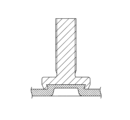
- 頭部上面に凹部の底面が平面であるかしめ用凹部を備えたかしめボルトを、その頭部を下向きとして金属板の表面に配置し、ダイスの表面に前記かしめボルトの前記かしめ用凹部よりも小径のリング状の凸状部を形成するとともに、この凸状部の中央部に底面が平坦な応力緩和用凹部を形成したかしめダイスを金属板の裏面に配置し、パンチで前記かしめボルトを金属板に貫通させることなく打ち込み、前記かしめダイスの表面の前記凸状部により金属材料を前記かしめ用凹部内に圧入し、前記かしめ用凹部内の中央部における金属材料の圧入距離を周縁部よりも小さくすることにより、前記かしめ用凹部内に圧入された金属材料の軸線方向の厚さを、前記かしめ用凹部の周縁部では薄く、中央部では厚くかつ一定とすることを特徴とするかしめボルトのかしめ固定方法。
- 頭部上面に凹部の底面が平面であるかしめ用凹部を備えたかしめボルトを金属板に貫通させることなくかしめ固定するために用いられるかしめダイスであって、ダイスの表面に前記かしめボルトの前記かしめ用凹部よりも小径のリング状の凸状部を形成するとともに、この凸状部の中央部に底面が平坦で孔のない応力緩和用凹部を形成したことを特徴とするかしめダイス。
Applications Claiming Priority (1)
| Application Number | Priority Date | Filing Date | Title |
|---|---|---|---|
| PCT/JP2020/024098 WO2021255912A1 (ja) | 2020-06-19 | 2020-06-19 | ボルトのかしめ固定構造、かしめボルトのかしめ固定方法及びかしめダイス |
Publications (3)
| Publication Number | Publication Date |
|---|---|
| JPWO2021255912A1 JPWO2021255912A1 (ja) | 2021-12-23 |
| JPWO2021255912A5 JPWO2021255912A5 (ja) | 2023-03-02 |
| JP7618178B2 true JP7618178B2 (ja) | 2025-01-21 |
Family
ID=79267699
Family Applications (1)
| Application Number | Title | Priority Date | Filing Date |
|---|---|---|---|
| JP2022531212A Active JP7618178B2 (ja) | 2020-06-19 | 2020-06-19 | ボルトのかしめ固定構造、かしめボルトのかしめ固定方法及びかしめダイス |
Country Status (5)
| Country | Link |
|---|---|
| US (1) | US12000422B2 (ja) |
| JP (1) | JP7618178B2 (ja) |
| CN (1) | CN115667736B (ja) |
| DE (1) | DE112020007083T5 (ja) |
| WO (1) | WO2021255912A1 (ja) |
Citations (1)
| Publication number | Priority date | Publication date | Assignee | Title |
|---|---|---|---|---|
| WO2012165151A1 (ja) | 2011-06-02 | 2012-12-06 | 株式会社青山製作所 | 嵌め部材の嵌め方法及び装置 |
Family Cites Families (25)
| Publication number | Priority date | Publication date | Assignee | Title |
|---|---|---|---|---|
| US3556189A (en) * | 1969-04-16 | 1971-01-19 | Penn Eng & Mfg Corp | Stud |
| US3820579A (en) * | 1971-03-29 | 1974-06-28 | Southco | Blind stud fastener |
| US4238165A (en) * | 1979-01-25 | 1980-12-09 | Illinois Tool Works Inc. | Fastener unit for clamping plastic workpieces |
| US5020950A (en) | 1990-03-06 | 1991-06-04 | Multifastener Corporation | Riveting fastener with improved torque resistance |
| JP2646423B2 (ja) * | 1993-12-14 | 1997-08-27 | 福井鋲螺株式会社 | 打込み同時かしめ金具 |
| DE19710246A1 (de) | 1997-03-12 | 1998-09-17 | Profil Verbindungstechnik Gmbh | Element und Verfahren zum Einsetzen des Elements in ein plattenförmiges Bauteil |
| US6146072A (en) | 1995-08-18 | 2000-11-14 | Profil Verbindungstechnik Gmbh & Co. Kg | Press form element, method of installation and assembly |
| DE19647831A1 (de) * | 1996-11-19 | 1998-05-20 | Profil Verbindungstechnik Gmbh | Verfahren zur Anbringung eines Funktionselementes; Funktionselement, Zusammenbauteil, Matrize und Setzkopf |
| AU7151298A (en) * | 1997-04-23 | 1998-11-13 | Fabristeel Products, Inc. | Fastener, die button and method of installing a fastener into a panel |
| CA2291127A1 (en) * | 1997-06-17 | 1998-12-23 | Stanley E. Wojciechowski | Fastener, die button and method of installing a fastener into a panel |
| US6527489B2 (en) * | 2000-12-07 | 2003-03-04 | International Business Machines Corporation | Concealed low distorting self crimping stud and insertion method |
| US6491487B1 (en) * | 2001-07-19 | 2002-12-10 | Fabristeel Products, Inc. | Double-ended self-attaching stud |
| US20050111934A1 (en) * | 2003-11-14 | 2005-05-26 | Ladouceur Harold A. | Self-riveting male fastener and panel assembly |
| JP2004324813A (ja) * | 2003-04-25 | 2004-11-18 | Honda Motor Co Ltd | かしめボルト |
| US8533928B2 (en) * | 2004-04-28 | 2013-09-17 | Profil Verbindungstechnik Gmbh & Co., Kg | Method and apparatus for the attachment of a fastener element to a component, in particular to a sheet metal part |
| US20060204348A1 (en) * | 2005-03-08 | 2006-09-14 | Shuart David M | Self-attaching fastener and fastener and panel assembly |
| US7380326B2 (en) * | 2005-11-02 | 2008-06-03 | Whitesell International Corporation | Method of attaching a self-attaching fastener to a panel |
| RU2418206C2 (ru) * | 2006-01-05 | 2011-05-10 | Профиль-Фербиндунгстехник Гмбх Унд Ко. Кг | Крепежный элемент, узловая сборка, состоящая из крепежного элемента и детали из листового металла, а также способ закрепления крепежного элемента на детали из листового металла |
| DE202006008721U1 (de) * | 2006-06-01 | 2007-10-11 | Profil Verbindungstechnik Gmbh & Co. Kg | Nietmutter und Kombination einer Nietmutter mit einem Blechteil |
| US8641342B2 (en) * | 2008-07-09 | 2014-02-04 | Newfrey Llc | Stud for stud welding |
| HUE027160T2 (en) * | 2008-11-21 | 2016-08-29 | Pem Man Inc | Spacer spike |
| DE102012001086A1 (de) * | 2012-01-20 | 2013-07-25 | Profil Verbindungstechnik Gmbh & Co. Kg | Bolzenelement und Verfahren zur Anbringung eines Bolzenelements an einem Bauteil aus einem Verbundwerkstoff |
| JP6214696B2 (ja) * | 2016-03-02 | 2017-10-18 | 株式会社青山製作所 | かしめボルト |
| JP2019138308A (ja) * | 2018-02-06 | 2019-08-22 | 株式会社ブリヂストン | ストラットアッパーマウント |
| JP2019138368A (ja) | 2018-02-09 | 2019-08-22 | 株式会社青山製作所 | かしめボルト |
-
2020
- 2020-06-19 JP JP2022531212A patent/JP7618178B2/ja active Active
- 2020-06-19 DE DE112020007083.2T patent/DE112020007083T5/de active Pending
- 2020-06-19 CN CN202080101377.XA patent/CN115667736B/zh active Active
- 2020-06-19 WO PCT/JP2020/024098 patent/WO2021255912A1/ja not_active Ceased
-
2022
- 2022-09-19 US US17/933,165 patent/US12000422B2/en active Active
Patent Citations (1)
| Publication number | Priority date | Publication date | Assignee | Title |
|---|---|---|---|---|
| WO2012165151A1 (ja) | 2011-06-02 | 2012-12-06 | 株式会社青山製作所 | 嵌め部材の嵌め方法及び装置 |
Also Published As
| Publication number | Publication date |
|---|---|
| WO2021255912A1 (ja) | 2021-12-23 |
| CN115667736A (zh) | 2023-01-31 |
| US20230014756A1 (en) | 2023-01-19 |
| CN115667736B (zh) | 2025-11-11 |
| US12000422B2 (en) | 2024-06-04 |
| DE112020007083T5 (de) | 2023-02-02 |
| JPWO2021255912A1 (ja) | 2021-12-23 |
Similar Documents
| Publication | Publication Date | Title |
|---|---|---|
| US9175715B2 (en) | Functional element having features providing security against rotation and also a component assembly consisting of the functional element and a sheet metal part | |
| JP2971120B2 (ja) | リベッティングファスナ | |
| JP4501408B2 (ja) | 締結方法 | |
| ES2702805T3 (es) | Procedimiento para montar un elemento funcional en una pieza de chapa | |
| US20060137166A1 (en) | Element attachable by riveting to a sheet metal part and also a component assembly and a method for the production of the component assembly | |
| JP6123082B2 (ja) | 高強度鋼板用ピアスナット | |
| CN114294316A (zh) | 用于螺钉连接的锁紧垫圈和螺钉连接 | |
| CN108884854B (zh) | 自冲式压入元件、压入连接部和用于制造这种压入连接部的方法 | |
| JP2009537757A (ja) | 自己挿通リベット | |
| EP2402620A1 (en) | Clinch bolt | |
| CN100383416C (zh) | 通过扩展实心盖板封装活动承窝组件的装置和方法 | |
| JPH11241714A (ja) | 素材、板状構成要素への素材取付け方法、構成要素アッセンブリーおよびダイスボタン | |
| US6527490B1 (en) | Punching, stamping rivet | |
| JP5056084B2 (ja) | 金属製板状体と柱状体とのカシメ組付品およびその製造方法、並びに製造装置。 | |
| JP7618178B2 (ja) | ボルトのかしめ固定構造、かしめボルトのかしめ固定方法及びかしめダイス | |
| JP2005226788A (ja) | ピアスナット | |
| JP5143678B2 (ja) | かしめねじ及びかしめねじ接合構造 | |
| TW201816291A (zh) | 用於薄片材料之緊固件 | |
| JP2022542650A (ja) | ピアスナットおよび閉じた断面形状を持つ相手部材の内面へのピアスナットの固定方法 | |
| CN101086270B (zh) | 可通过铆接连接到金属薄板部件上的元件和一种零件总成 | |
| JP3190264B2 (ja) | Tナットの製造方法 | |
| JP4361511B2 (ja) | ボス部材及びボス部材の製造方法 | |
| JPH05202917A (ja) | ピアスナット | |
| JP4834027B2 (ja) | かしめねじ、かしめねじの製造方法及びかしめねじの接合構造 | |
| JP7560330B2 (ja) | ナット |
Legal Events
| Date | Code | Title | Description |
|---|---|---|---|
| A524 | Written submission of copy of amendment under article 19 pct |
Free format text: JAPANESE INTERMEDIATE CODE: A527 Effective date: 20220915 |
|
| A621 | Written request for application examination |
Free format text: JAPANESE INTERMEDIATE CODE: A621 Effective date: 20230405 |
|
| A131 | Notification of reasons for refusal |
Free format text: JAPANESE INTERMEDIATE CODE: A131 Effective date: 20240206 |
|
| A521 | Request for written amendment filed |
Free format text: JAPANESE INTERMEDIATE CODE: A523 Effective date: 20240318 |
|
| A131 | Notification of reasons for refusal |
Free format text: JAPANESE INTERMEDIATE CODE: A131 Effective date: 20240521 |
|
| A521 | Request for written amendment filed |
Free format text: JAPANESE INTERMEDIATE CODE: A523 Effective date: 20240708 |
|
| A02 | Decision of refusal |
Free format text: JAPANESE INTERMEDIATE CODE: A02 Effective date: 20240813 |
|
| A521 | Request for written amendment filed |
Free format text: JAPANESE INTERMEDIATE CODE: A523 Effective date: 20241107 |
|
| A911 | Transfer to examiner for re-examination before appeal (zenchi) |
Free format text: JAPANESE INTERMEDIATE CODE: A911 Effective date: 20241114 |
|
| TRDD | Decision of grant or rejection written | ||
| A01 | Written decision to grant a patent or to grant a registration (utility model) |
Free format text: JAPANESE INTERMEDIATE CODE: A01 Effective date: 20241224 |
|
| A61 | First payment of annual fees (during grant procedure) |
Free format text: JAPANESE INTERMEDIATE CODE: A61 Effective date: 20241224 |
|
| R150 | Certificate of patent or registration of utility model |
Ref document number: 7618178 Country of ref document: JP Free format text: JAPANESE INTERMEDIATE CODE: R150 |