JP7602829B2 - Game program, information processing device, and method - Google Patents
Game program, information processing device, and method Download PDFInfo
- Publication number
- JP7602829B2 JP7602829B2 JP2023175894A JP2023175894A JP7602829B2 JP 7602829 B2 JP7602829 B2 JP 7602829B2 JP 2023175894 A JP2023175894 A JP 2023175894A JP 2023175894 A JP2023175894 A JP 2023175894A JP 7602829 B2 JP7602829 B2 JP 7602829B2
- Authority
- JP
- Japan
- Prior art keywords
- virtual
- space
- view
- virtual camera
- angle
- Prior art date
- Legal status (The legal status is an assumption and is not a legal conclusion. Google has not performed a legal analysis and makes no representation as to the accuracy of the status listed.)
- Active
Links
- 230000010365 information processing Effects 0.000 title claims description 67
- 238000000034 method Methods 0.000 title description 56
- 230000008859 change Effects 0.000 claims description 81
- 238000003384 imaging method Methods 0.000 claims description 78
- 238000013459 approach Methods 0.000 claims description 17
- 230000004044 response Effects 0.000 claims description 6
- 230000004048 modification Effects 0.000 description 73
- 238000012986 modification Methods 0.000 description 73
- 230000008569 process Effects 0.000 description 51
- 238000010586 diagram Methods 0.000 description 32
- 238000012545 processing Methods 0.000 description 27
- 230000009466 transformation Effects 0.000 description 23
- 239000011159 matrix material Substances 0.000 description 18
- 239000003550 marker Substances 0.000 description 15
- 230000006870 function Effects 0.000 description 14
- 238000005516 engineering process Methods 0.000 description 12
- 230000000694 effects Effects 0.000 description 5
- 230000003278 mimic effect Effects 0.000 description 4
- 230000000007 visual effect Effects 0.000 description 4
- 230000000052 comparative effect Effects 0.000 description 3
- 239000002131 composite material Substances 0.000 description 3
- 230000001131 transforming effect Effects 0.000 description 3
- 230000003190 augmentative effect Effects 0.000 description 2
- 230000005540 biological transmission Effects 0.000 description 2
- 238000004891 communication Methods 0.000 description 2
- 239000004065 semiconductor Substances 0.000 description 2
- 230000001133 acceleration Effects 0.000 description 1
- 230000008901 benefit Effects 0.000 description 1
- 230000007423 decrease Effects 0.000 description 1
- 239000004973 liquid crystal related substance Substances 0.000 description 1
- 238000009877 rendering Methods 0.000 description 1
- 238000004904 shortening Methods 0.000 description 1
- 230000002194 synthesizing effect Effects 0.000 description 1
- 230000001052 transient effect Effects 0.000 description 1
Images


Landscapes
- User Interface Of Digital Computer (AREA)
Description
本発明は、AR技術を用いて仮想オブジェクトを表示する技術に関する。 The present invention relates to a technology for displaying virtual objects using AR technology.
AR(Augmented Reality)技術を用いて仮想オブジェクトを表示する技術が知られている。例えば、特許文献1には、携帯型ディスプレイと、当該携帯型ディスプレイの表示面の裏面方向に撮像方向を向けて取り付けられた撮像手段と、を含む表示装置が記載されている。当該表示装置は、撮像手段を用いて撮像された実画像を背景として、仮想オブジェクトを重畳させた合成画像を、当該携帯型ディスプレイに表示する。当該表示装置を動かすと、携帯型ディスプレイに表示される仮想オブジェクトの大きさが変化する。
Technology for displaying virtual objects using AR (Augmented Reality) technology is known. For example,
ところで、コンピュータを用いて、競技を模したゲーム(例えば、サッカーゲーム等)を実現することが知られている。このようなゲームをAR技術によって実現する場合、仮想的な競技場に配置された選手キャラクタに向かって、上述の表示装置を向けながら操作するゲームが考えられる。この場合、ユーザは、選手キャラクタの表示サイズを大きくするために、上述の表示装置を選手キャラクタに近づける操作を行う。しかしながら、上述の表示装置を選手キャラクタに近づけて選手の表示サイズを大きくすることには限界があり、選手キャラクタの視認性が良くない。 It is known that games that mimic sports (such as soccer games) can be realized using a computer. When realizing such a game using AR technology, it is conceivable that the game can be played while pointing the above-mentioned display device at a player character placed on a virtual stadium. In this case, the user performs an operation to move the above-mentioned display device closer to the player character in order to increase the display size of the player character. However, there is a limit to how much the above-mentioned display device can be brought closer to the player character to increase the display size of the player, and the visibility of the player character is poor.
本発明の一態様は、上述の課題を解決するためになされたものであり、AR技術によって実現される競技を模したゲームにおいて、選手キャラクタの視認性を向上させることを目的とする。 One aspect of the present invention has been made to solve the above-mentioned problems, and aims to improve the visibility of player characters in games that mimic sports realized using AR technology.
上記の課題を解決するために、本発明の一態様に係るゲームプログラムは、競技を模したゲームを実現するために、撮像装置と表示装置とを含むコンピュータに、現実空間との位置関係が規定された仮想空間であって、前記現実空間での前記撮像装置の位置に対応する前記仮想空間での位置に仮想カメラが配置される仮想空間に、選手キャラクタを配置する配置ステップと、前記現実空間での前記撮像装置の動きに応じて、前記仮想カメラの画角を変更する変更ステップと、前記仮想空間が前記仮想カメラによって撮影される仮想画像を、前記現実空間が前記撮像装置によって撮像される現実画像に重畳して前記表示装置に表示する表示ステップと、を実行させ、前記変更ステップでは、前記選手キャラクタが配置された領域に前記仮想カメラが近いほど、前記仮想カメラの画角を狭くする。 To solve the above problems, a game program according to one aspect of the present invention executes, in a computer including an imaging device and a display device, a placement step of placing a player character in a virtual space in which a positional relationship with a real space is defined, in which a virtual camera is placed at a position in the virtual space corresponding to the position of the imaging device in the real space, a modification step of changing the angle of view of the virtual camera in accordance with the movement of the imaging device in the real space, and a display step of superimposing a virtual image of the virtual space captured by the virtual camera on a real image of the real space captured by the imaging device and displaying the superimposed image on the display device, and in the modification step, the angle of view of the virtual camera is narrowed as the virtual camera is closer to the area in which the player character is placed.
〔実施形態1〕
以下、本発明の実施形態1に係る情報処理装置10について、詳細に説明する。
[Embodiment 1]
The
<情報処理装置10の概要>
情報処理装置10は、競技を模したゲームをAR(Augmented Reality)技術を用いて実現する装置である。本実施形態では、競技としてサッカーを適用する。以降、本発明におけるゲームを、サッカーゲームとも記載する。
<Overview of
The
図1は、ユーザが、情報処理装置10を用いてサッカーゲームをプレイする様子を模式的に示す図である。図1に示すように、情報処理装置10は、カメラ14およびタッチパネル15(表示装置17)を備えた携帯型のコンピュータによって構成される。情報処理装置10において表示装置17が備えられた面を「おもて面」とすると、カメラ14は「裏面」に備えられている。カメラ14の撮像方向は、「おもて面」から「裏面」に向かう方向である。
Figure 1 is a diagram that shows a user playing a soccer game using an
図1に示すように、ユーザは、情報処理装置10を保持し、現実空間に存在するテーブルR1上のマーカR2にカメラ14を向けて、サッカーゲームのプレイを開始する。マーカR2は、円板状の物体であり、表面に所定のパターン(図2の例では、星マークのパターン)を有する。表示装置17には、現実空間を示す現実画像に、仮想空間を示す仮想画像が重畳された合成画像が表示される。仮想空間は、サッカーゲームをプレイするための仮想オブジェクトが配置される仮想的な三次元空間である。表示装置17に表示される合成画像は、現実空間と仮想空間とが合成された空間の視野画像を表している。以降、現実空間と仮想空間とが合成された空間を、仮想現実空間とも記載する。
As shown in FIG. 1, a user holds an
図2は、仮想現実空間の一例を模式的に示す図である。図2に示すように、仮想現実空間では、現実空間に存在するテーブルR1の天板上に、仮想空間に存在する仮想的なサッカーフィールドを構成するオブジェクトV1a~V1fと、複数の選手キャラクタV2と、サッカーボールV3とが配置される。仮想的なサッカーフィールドにおけるフィールド領域Fは、タッチラインを示す2本のオブジェクトV1a、およびゴールラインを示す2本のオブジェクトV1bによって区画される。また、フィールド領域F内には、センターサークルを示すオブジェクトV1cが配置される。本実施形態では、センターサークルを示すオブジェクトV1cは、マーカR2の円周に沿って配置される。また、フィールド領域F内には、ペナルティアーク、ペナルティエリアおよびゴールエリアをそれぞれ区画するライン等といった、その他の各種ラインを示すオブジェクトV1dが配置される。また、フィールド領域F周辺には、ゴールを示すオブジェクトV1e、コーナーポールを示すオブジェクトV1fが配置される。なお、仮想的なサッカーフィールドを構成する仮想オブジェクトは、オブジェクトV1a~V1fに限定されず、その他の仮想オブジェクトを含んでいてもよい。以降、仮想的なサッカーフィールドを構成するオブジェクトV1a~V1fを特に区別して説明する必要がない場合には、単にオブジェクトV1とも記載する。 2 is a diagram showing an example of a virtual reality space. As shown in FIG. 2, in the virtual reality space, objects V1a to V1f constituting a virtual soccer field existing in the virtual space, a plurality of player characters V2, and a soccer ball V3 are arranged on the top plate of a table R1 existing in the real space. A field area F in the virtual soccer field is divided by two objects V1a indicating touch lines and two objects V1b indicating goal lines. An object V1c indicating a center circle is also arranged in the field area F. In this embodiment, the object V1c indicating the center circle is arranged along the circumference of the marker R2. An object V1d indicating various other lines, such as lines dividing the penalty arc, penalty area, and goal area, is also arranged in the field area F. An object V1e indicating a goal and an object V1f indicating a corner pole are also arranged around the field area F. Note that the virtual objects constituting the virtual soccer field are not limited to the objects V1a to V1f, and may include other virtual objects. Hereinafter, when there is no need to distinguish between the objects V1a to V1f that make up the virtual soccer field, they will simply be referred to as object V1.
また、仮想空間に配置された各選手キャラクタV2およびサッカーボールV3は、ゲームの進行に伴い、仮想的なサッカーフィールドが配置された面上を移動する。ユーザは、操作したい選手キャラクタの移動に伴い、タッチパネル15に表示される視野画像に当該選手キャラクタを含めるよう情報処理装置10本体を動かしながら、サッカーゲームをプレイする。ユーザが情報処理装置10本体を動かすと、カメラ14によって撮像される現実空間の範囲が変化し、それに伴って、タッチパネル15に表示される仮想現実空間の視野画像も変化する。
In addition, each player character V2 and soccer ball V3 arranged in the virtual space moves on the surface on which the virtual soccer field is arranged as the game progresses. The user plays the soccer game by moving the
<情報処理装置10のハードウェア構成>
図3は、情報処理装置10のハードウェア構成の一例を示すブロック図である。情報処理装置10は、プロセッサ11と、主メモリ12と、補助メモリ13と、カメラ14と、タッチパネル15と、位置センサ16を含むコンピュータによって構成される。タッチパネル15は、表示装置17および入力装置18を含む。カメラ14は、本発明における撮像装置の一例である。プロセッサ11と、主メモリ12と、補助メモリ13と、カメラ14と、タッチパネル15と、位置センサ16とは、バスを介して互いに接続される。なお、情報処理装置10を構成するコンピュータは、ネットワークを介して他の装置と通信可能な通信インタフェース(図示せず)をさらに含んでいてもよい。
<Hardware configuration of
3 is a block diagram showing an example of a hardware configuration of the
プロセッサ11としては、例えば、マイクロプロセッサ、デジタルシグナルプロセッサ、マイクロコントローラ、またはこれらの組み合わせ等が用いられる。
The
主メモリ12としては、例えば、半導体RAM等が用いられる。
For example, a semiconductor RAM or the like is used as the
補助メモリ13としては、例えば、フラッシュメモリ、HDD、SSD、可搬型記憶媒体、またはこれらの組み合わせ等が用いられる。
The
補助メモリ13には、情報処理装置10を構成するコンピュータに実行させる本実施形態に係るゲームプログラムおよび各種プログラムが記憶される。本実施形態に係るゲームプログラムは、競技を模したゲーム(サッカーゲーム)を実現するために、撮像装置(カメラ14)と表示装置17とを含むコンピュータに、現実空間との位置関係が規定された仮想空間であって、現実空間での撮像装置(カメラ14)の位置に対応する仮想空間での位置に仮想カメラが配置される仮想空間に、選手キャラクタV2を配置する配置ステップと、現実空間での撮像装置(カメラ14)の動きに応じて、仮想カメラの画角を変更する変更ステップと、仮想空間が仮想カメラによって撮影される仮想画像を、現実空間が撮像装置によって撮像される現実画像に重畳して表示装置に表示する表示ステップと、を実行させ、変更ステップでは、選手キャラクタV2が配置された領域に仮想カメラが近いほど、仮想カメラの画角を狭くするものである。プロセッサ11は、補助メモリ13に格納されたゲームプログラムおよび各種プログラムを主メモリ12上に展開し、展開したゲームプログラムに含まれる各命令を実行する。
The
また、補助メモリ13には、当該コンピュータを情報処理装置10として動作させるためにプロセッサ11が参照する各種データが格納されている。
The
カメラ14は、レンズおよびイメージセンサを含み、レンズから入射する光をイメージセンサにより受光して撮像画像を生成する。撮像画像は、レンズが向けられた方向(撮像方向)を基準として画角の範囲に含まれる周囲の様子を示す。画角は、レンズの特性により固定であるか、または、所定範囲で変動可能である。本実施形態では、カメラ14に含まれるレンズは、画角が固定の単焦点レンズであるものとする。
タッチパネル15は、液晶ディスプレイ等の表示装置17と、タッチパッド等の入力装置18とが一体として組み合わせられた装置である。タッチパネル15は、画像を表示した表示装置17に対する接触操作を入力装置18により検知する。
The
位置センサ16は、情報処理装置10の位置および傾きを検出する。例えば、位置センサ16は、ジャイロセンサ、加速度センサ、地磁気センサ、GPS(Global Positioning System)受信機、またはこれらの組み合わせによって構成される。
The
<情報処理装置10の機能的な構成>
図4は、情報処理装置10の機能的な構成を示すブロック図である。情報処理装置10は、配置部111と、変更部112と、表示部113と、AR制御部114と、ゲーム進行部115とを含む。
<Functional configuration of
4 is a block diagram showing the functional configuration of the
配置部111は、現実空間との位置関係が規定された仮想空間であって、現実空間でのカメラ14の位置に対応する仮想空間での位置に仮想カメラが配置される仮想空間に、選手キャラクタV2を配置する。配置部111の詳細な構成については後述する。
The
変更部112は、現実空間でのカメラ14の動きに応じて、仮想カメラの画角を変更する。また、変更部112は、選手キャラクタV2が配置された領域に仮想カメラが近いほど、仮想カメラの画角を狭くする。変更部112の詳細な構成については後述する。
The
表示部113は、仮想空間が仮想カメラによって撮影される仮想画像を、現実空間がカメラ14によって撮像される現実画像に重畳して表示装置17に表示する。表示部113の詳細な構成については後述する。
The
AR制御部114は、現実空間との位置関係を規定した仮想空間を生成し、生成した仮想空間に仮想カメラを配置する。ここで、仮想空間に仮想カメラを配置することは、仮想空間における視点を設定することに相当する。また、AR制御部114は、規定した位置関係に整合するように仮想画像を現実画像に重畳するための各種情報を算出する。各種情報には、仮想カメラの画角を示す情報が含まれる。ここで、仮想カメラの画角は、視野角と呼ばれることもある。なお、AR制御部114が算出する各種情報には、画角そのものを示す情報が含まれていてもよいし、画角を算出するためのパラメータ(例えば、焦点距離および仮想カメラの幅)が含まれていてもよい。以降、「画角を示す情報を算出(または取得)する」ことを、単に、「画角を算出(または取得)する」とも記載する。また、「画角を示す情報を参照して画角を変更する」ことを、単に、「画角を変更する」とも記載する。算出された各種情報は、他の各部(配置部111、変更部112、表示部113、およびゲーム進行部115)によって参照される。AR制御部114の詳細な構成については後述する。
The
ゲーム進行部115は、サッカーゲームの進行に係る処理を行う。ゲーム進行部115は、入力装置18を用いたユーザの操作に基づいて、選手キャラクタV2を動作させることにより、サッカーゲームを進行させる。ゲーム進行部115は、サッカーゲームを、シングルプレイゲームとして進行してもよいし、マルチプレイゲームとして進行してもよい。シングルプレイゲームの場合、ゲーム進行部115は、ユーザによって操作可能な選手キャラクタV2からなるユーザチームと、ユーザの操作によらずにゲーム進行部115によって動作が決定される選手キャラクタV2からなる相手チームとを対戦させる。また、マルチプレイゲームの場合、ゲーム進行部115は、ユーザによって操作可能な選手キャラクタV2からなるユーザチームと、他の情報処理装置10を操作する他のユーザによって操作可能な選手キャラクタV2からなる相手チームとを対戦させる。
The
(AR制御部の詳細な構成例)
AR制御部114の詳細な構成例について説明する。AR制御部114は、(1)仮想空間を生成する機能、(2)仮想カメラを配置(視点を設定)する機能、(3)現実空間における特定の物体の仮想空間での位置を算出する機能、を有する。なお、AR制御部114は、これらの機能を有する公知の技術によって構成可能である。各機能の詳細について以下に説明する。
(Detailed configuration example of AR control unit)
A detailed configuration example of the
(1)仮想空間を生成する機能
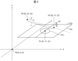
AR制御部114は、現実空間との位置関係を規定した仮想空間を生成する。図5は、AR制御部114によって生成される仮想空間の一例を示す図である。図5に示すように、AR制御部114は、当該機能ブロックが起動された時点で情報処理装置10本体が存在する現実空間の位置を原点P0とし、現実空間における水平面をXZ平面とし、現実空間における垂直方向をY軸方向とする仮想空間のグローバル座標系を生成する。なお、グローバル座標は、ワールド座標とも呼ばれる。情報処理装置10本体が現実空間において存在する位置、および現実空間における水平面は、位置センサ16により検出可能である。
(1) Function of generating virtual space The
(2)仮想カメラを配置する機能
また、AR制御部114は、仮想空間に仮想カメラを配置(視点を設定)する。具体的には、図5に示すように、AR制御部114は、情報処理装置10本体(カメラ14)の現実空間での位置に対応する仮想空間での位置P2(X2,Y2,Z2)に、仮想カメラを配置する。なお、P2(X2,Y2,Z2)は、グローバル座標系における座標を示している。また、AR制御部114は、カメラ14の現実空間での撮像方向に対応する仮想空間での方向dを向くように、仮想カメラの撮像方向を設定する。なお、カメラ14の現実空間での位置および撮像方向は、位置センサ16により検出可能である。
(2) Function of Placing a Virtual Camera The
また、AR制御部114は、カメラ14の動きに応じて、仮想カメラの配置を更新する。カメラ14の動きとは、カメラ14の現実空間での位置および撮像方向の一方または両方が変化することである。ユーザが情報処理装置10を保持して動かすと、カメラ14の現実空間での位置および撮像方向の一方または両方が変化する。AR制御部114は、カメラ14の現実空間での位置および撮像方向に対応するよう、仮想カメラの仮想空間での位置および撮像方向を更新する。
The
また、AR制御部114は、現実空間および仮想空間の間に規定された位置関係に整合するように仮想画像を現実画像に重畳するための、仮想カメラの画角を算出する。例えば、そのような仮想カメラの画角は、カメラ14の画角と同一の値である。AR制御部114は、例えば、補助メモリ13に記憶されたカメラ14の画角を取得し、取得した画角を仮想カメラの画角として設定する。
The
(3)現実空間における特定の物体の仮想空間での位置を算出する機能
AR制御部114は、現実空間における特定の物体の仮想空間での位置を算出する。具体的には、AR制御部114は、カメラ14から取得した現実画像において特定の物体を含む領域を検出し、検出した領域が示す物体の現実空間での位置を解析する。また、AR制御部114は、解析した現実空間での位置に対応する仮想空間での位置を算出する。本実施形態では、特定の物体として、所定のパターン(この例では、星マーク)を表面に有するマーカR2が設定されている。また、特定の物体は、形状および大きさが規定されている。この例では、マーカR2は、円形であり、その直径が規定されている。そこで、AR制御部114は、現実画像に含まれる所定のパターンを有する領域の形状および大きさと、マーカRに規定された形状および大きさとに基づいて、マーカR2の現実空間での位置および対応する仮想空間での位置を算出する。例えば、図5の例では、マーカR2の仮想空間での位置として、グローバル座標系における点P(X1,Y1,Z1)が算出されている。
(3) Function of calculating the position of a specific object in a virtual space in a real space The
(配置部111の詳細な構成)
配置部111は、AR制御部114によって生成された仮想空間に、複数の選手キャラクタV2を含む仮想オブジェクトを配置する。具体的には、配置部111は、AR制御部114によって算出されたマーカR2のグローバル座標を取得し、当該グローバル座標を原点としたローカル座標系を設定する。図5の例では、マーカR2の位置P1(X1,Y1,Z1)を原点とし、XZ平面に平行な面をxz平面とし、Y軸方向に平行な方向をy軸方向とするローカル座標系が設定される。また、図5に示すように、配置部111は、ローカル座標系のxz平面に、仮想的なサッカーフィールドを構成する各種のオブジェクトV1を配置する。各種のオブジェクトV1は、仮想的なサッカーフィールドの中心がローカル座標系の原点となるように配置される。また、配置部111は、各種のオブジェクトV1の配置により区画されるフィールド領域Fに、複数の選手キャラクタV2を配置する。なお、図5では、各種オブジェクトV1の一部および複数の選手キャラクタV2の一部を示し、他の一部の図示を省略している。また、配置部111は、サッカーゲームの進行に伴い、各選手キャラクタV2のローカル座標系における位置を移動する。
(Detailed configuration of placement unit 111)
The
(変更部112の詳細な構成)
変更部112の詳細な構成について説明する。変更部112は、現実空間でのカメラ14の動きに応じて仮想カメラの画角を変更する処理において、選手キャラクタV2が配置された領域に仮想カメラが近いほど、仮想カメラの画角を狭くする。以降、画角を変更する処理を、画角変更処理とも記載する。ここで、本実施形態では、「選手キャラクタV2が配置された領域」として、フィールド領域Fを適用する。つまり、変更部112は、フィールド領域Fに仮想カメラが近いほど、仮想カメラの画角を狭くするよう画角変更処理を実行する。フィールド領域Fと仮想カメラとの距離を算出するための具体的な構成については後述する。
(Detailed configuration of the change unit 112)
A detailed configuration of the
画角変更処理には、仮想カメラがフィールド領域Fに近づくにつれて画角を狭くする処理が含まれる。また、画像変更処理には、仮想カメラがフィールド領域Fから遠ざかるにつれて画角を広くする処理が含まれる。 The angle of view change process includes a process of narrowing the angle of view as the virtual camera approaches the field area F. The image change process includes a process of widening the angle of view as the virtual camera moves away from the field area F.
また、変更部112は、現実空間および仮想空間との位置関係に整合するように仮想画像を現実画像に重畳するための仮想カメラの画角を取得し、取得した画角を変更する。ここで、「現実空間および仮想空間との位置関係に整合するように仮想画像を現実画像に重畳するための仮想カメラの画角」は、前述したように、AR制御部114によって算出される。換言すると、変更部112は、AR制御部114によって算出された仮想カメラの画角を取得し、取得した画角を変更する。
The
ここで、AR制御部114が公知の技術によって実現される場合、補助メモリ13には、上述した本実施形態に係るゲームプログラムに加えて、情報処理装置10をAR制御部114として機能させるための公知のプログラムが記憶されている。変更部112が、AR制御部114から取得した画角を変更するよう構成されることにより、本実施形態に係るゲームプログラムの移植性、再利用性を向上させることができる。
Here, when the
また、変更部112は、フィールド領域Fと仮想カメラとの距離として、仮想カメラの位置と、当該仮想カメラから撮像方向に伸びる直線がフィールド領域Fに交わる交点との距離を適用する。
In addition, the
具体的には、変更部112は、仮想カメラと、当該仮想カメラから撮像方向に伸びる直線が、選手キャラクタV2が配置された領域(本実施形態ではフィールド領域F)に交わる交点との距離Lが小さいほど、仮想カメラの画角を狭くする。換言すると、変更部112は、仮想カメラから撮像方向に伸びる直線がフィールド領域Fに交わらない場合には、仮想カメラの画角を狭くする処理を行わない。
Specifically, the smaller the distance L between the virtual camera and the intersection point where a straight line extending from the virtual camera in the imaging direction intersects with the area in which the player character V2 is located (in this embodiment, the field area F), the narrower the angle of view of the virtual camera is made by the
具体的には、変更部112は、AR制御部114によって算出された仮想カメラの位置および撮像方向を取得することにより、上述した交点の位置を算出する。図5の例では、変更部112は、仮想カメラの位置P2から撮像方向dに伸びる直線が、フィールド領域Fに交わる交点P3(X3,Y1,Z3)を算出する。また、変更部112は、仮想カメラの位置P2から交点P3までの距離Lを算出する。
Specifically, the
なお、変更部112は、画角を狭くする処理を、仮想カメラの位置P2と上述の交点P3との距離Lが閾値L1より大きい場合は実行せず、閾値L1以下の場合に実行する。また、変更部112は、画角を狭くする処理を、上述の距離Lが閾値L2(L2<L1)より小さい場合は実行しなくてもよい。この場合、換言すると、変更部112は、画角を狭くする処理を、距離LがL2以上L1以下の範囲で実行する。また、変更部112は、仮想カメラがフィールド領域Fに近づくにしたがって画角を連続的に変化させる。
The
図6~図7を用いて、距離LがL2以上L1以下の範囲における画角変更処理の具体例について説明する。図6および図7は、それぞれ、仮想的なサッカーフィールドを仮想空間において上面視した図である。なお、図6および図7では、各種オブジェクトV1の一部および複数の選手キャラクタV2の一部を示し、他の一部については図示を省略している。 A specific example of the angle of view change process when the distance L is in the range of L2 to L1 will be described using Figures 6 to 7. Figures 6 and 7 each show a top view of a virtual soccer field in a virtual space. Note that Figures 6 and 7 show some of the various objects V1 and some of the multiple player characters V2, with the rest not shown.
図6では、交点P3までの距離L=L1となる位置P2に仮想カメラが配置されている。このとき、仮想カメラの画角は、AR制御部114によって設定された画角r1である。
In FIG. 6, the virtual camera is placed at position P2 where the distance L to intersection point P3 is L1. At this time, the angle of view of the virtual camera is angle of view r1 set by the
図7では、交点P3までの距離L=L2となる位置P2に仮想カメラが配置されている。このとき、仮想カメラの画角は、最小画角r2(r2<r1)である。最小画角r2としては、画角r1より小さい値があらかじめ設定される。 In FIG. 7, the virtual camera is placed at position P2 where the distance to intersection point P3 is L=L2. At this time, the angle of view of the virtual camera is minimum angle of view r2 (r2<r1). The minimum angle of view r2 is preset to a value smaller than the angle of view r1.
この場合、変更部112は、距離Lが閾値L1より大きい場合は、AR制御部114によって算出された仮想カメラの画角r1を、変更せずにそのまま設定する。また、変更部112は、距離Lが閾値L2より小さい場合は、仮想カメラの画角を最小画角r2に設定する。また、変更部112は、距離LがL2以上L1以下の場合は、距離L1に対する画角r1から距離L2に対する画角r2まで、連続的に(例えば、線形的に)画角を変化させる。なお、画角の連続的な変化は、線形変化であってもよいし、その他の連続的な変化であってもよい。例えば、変更部112は、仮想カメラがフィールド領域Fに近づくほど画角の変化率を大きくしてもよい。
In this case, when the distance L is greater than the threshold value L1, the
このように、選手キャラクタの表示サイズが、情報処理装置10(すなわちカメラ14)を選手キャラクタV2に近づけた分以上に大きくなるのは、仮想カメラをフィールド領域Fに閾値L1以下の距離まで近づけた場合に限られる。また、仮想カメラがフィールド領域Fから閾値L1より離れている場合には、選手キャラクタは距離相応の表示サイズで表示される。このため、ユーザにとって、表示サイズの変化がより自然なものとなる。また、ユーザは、仮想カメラからフィールド領域Fまでの距離を調整することにより、選手キャラクタV2の表示サイズが連続的に変化するので、好みの表示サイズで選手キャラクタV2を表示させることができる。また、仮想カメラがフィールド領域Fに近づくほど画角の変化率を大きくする場合、ユーザは、仮想カメラを選手キャラクタV2に近づけるほど、より急激に選手キャラクタV2の表示サイズを大きくすることができる。 In this way, the display size of the player character increases by more than the amount by which the information processing device 10 (i.e., the camera 14) is brought closer to the player character V2 only when the virtual camera is brought closer to the field area F to a distance equal to or less than the threshold L1. Also, when the virtual camera is farther away from the field area F than the threshold L1, the player character is displayed at a display size appropriate to the distance. This makes the change in display size more natural to the user. Also, by adjusting the distance from the virtual camera to the field area F, the display size of the player character V2 changes continuously, so that the user can display the player character V2 at a display size of their choice. Also, if the rate of change of the angle of view is increased as the virtual camera approaches the field area F, the user can increase the display size of the player character V2 more rapidly as the virtual camera is brought closer to the player character V2.
(表示部113の詳細な構成)
表示部113の詳細な構成について説明する。表示部113は、配置部111によって各種オブジェクトV1および選手キャラクタV2が配置された仮想空間を、変更部112によって変更された画角を適用した仮想カメラを用いて撮像した仮想画像を生成する。また、表示部113は、カメラ14によって生成された現実画像に、生成した仮想画像を重畳して、表示装置17に表示する。
(Detailed configuration of display unit 113)
A detailed configuration of the
<情報処理装置10の動作>
以上のように構成された情報処理装置10の動作について説明する。情報処理装置10は、競技を模したゲームを実現するために、現実空間との位置関係が規定された仮想空間であって、現実空間でのカメラ14の位置に対応する仮想空間での位置に仮想カメラが配置される仮想空間に、選手キャラクタを配置する配置ステップと、現実空間でのカメラ14の動きに応じて、仮想カメラの画角を変更する変更ステップと、仮想空間が仮想カメラによって撮影される仮想画像を、現実空間がカメラ14によって撮像される現実画像に重畳して表示装置17に表示する表示ステップと、を実行し、変更ステップは、選手キャラクタが配置された領域(本実施形態ではフィールド領域F)に仮想カメラが近いほど、仮想カメラの画角を狭くする。
<Operation of
The operation of the
図8は、情報処理装置10の動作を説明するフローチャートである。
Figure 8 is a flowchart explaining the operation of the
ステップS100において、ゲーム進行部115は、サッカーゲームを開始する処理を実行する。開始する処理には、例えば、ユーザチームと相手チームとを示す情報を取得する処理、各チームにそれぞれ含まれる選手キャラクタを示す情報を取得する処理等が含まれる。
In step S100, the
ステップS102において、AR制御部114は、現実空間との位置関係が規定された仮想空間を生成する。具体的には、AR制御部114は、このステップを実行する時点における情報処理装置10(すなわち、カメラ14)の現実空間における位置を原点とする仮想空間のグローバル座標系を生成する。また、AR制御部114は、グローバル座標の原点に、カメラ14の撮像方向に対応する方向に向けて、仮想カメラを配置する。
In step S102, the
ステップS104において、AR制御部114は、仮想カメラの現時点での配置に関わる情報と、位置センサ16から得られる情報とに基づいて、仮想空間に仮想カメラを再配置する。具体的には、AR制御部114は、情報処理装置10の現実空間における位置および撮像方向に基づいて、仮想空間における位置P2に、撮像方向dに向けて仮想カメラを再配置する。以降、AR制御部114は、カメラ14の動きに伴い仮想カメラの配置を更新する。また、AR制御部114は、カメラ14の画角を、仮想カメラの画角として設定する。
In step S104, the
ステップS106において、AR制御部114は、現実空間に存在するマーカR2の仮想空間での位置P1を算出する。
In step S106, the
ステップS108において、ゲーム進行部115は、サッカーゲームを進行する処理を実行する。進行する処理には、例えば、マーカR2の位置P1を原点とするローカル座標系を生成する処理、ローカル座標をグローバル座標(ワールド座標ともいう)に変換するためのワールド座標変換行列を生成する処理、ユーザの操作に応答して選手キャラクタV2およびサッカーボールV3の移動先を更新する処理等が含まれる。
In step S108, the
ステップS110において、配置部111は、仮想空間に、仮想的なサッカーフィールドを構成する各種オブジェクトV1を配置する。具体的には、配置部111は、ローカル座標系のxz平面に各種オブジェクトV1を配置する。
In step S110, the
ステップS112において、配置部111は、仮想空間に、選手キャラクタV2等を配置する。具体的には、配置部111は、ステップS108におけるゲームの進行に従って、ローカル座標系のxz平面に配置されたオブジェクトV1によって区画されるフィールド領域F内に、複数の選手キャラクタV2、サッカーボールV3等を配置する。換言すると、配置部111は、選手キャラクタV2、サッカーボールV3等の仮想空間におけるローカル座標を更新する。
In step S112, the
ステップS114において、変更部112は、AR制御部114によって算出された仮想カメラの画角を取得する。
In step S114, the
ステップS116において、変更部112は、仮想カメラの位置P2と交点P3との距離Lを取得する。
In step S116, the
ステップS118において、変更部112は、画角変更条件が満たされるか否かを判断する。画角変更条件とは、ここでは、ステップS116で取得した距離Lが、閾値L1以下であり、かつ、閾値L2以上であるとの条件である。ステップS118でNoの場合、後述するステップS122の処理が実行される。ステップS118でYesの場合、次のステップS120の処理が実行される。
In step S118, the
ステップS120において、変更部112は、仮想カメラの位置P2と交点P3との距離Lが近いほど画角を狭くするよう、画角を変更する。なお、今回の処理フローにおいて取得された距離Lが、前回の処理フローにおいて取得された距離Lより小さい場合、仮想カメラは、前回よりもフィールド領域Fに近づいている。この場合、変更部112は、画角を前回よりも狭くする。一方、今回の処理フローにおいて取得された距離Lが、前回の処理フローにおいて取得された距離Lより大きい場合、仮想カメラは、前回よりもフィールド領域Fから遠ざかっている。この場合、変更部112は、画角を前回よりも広くする。当該ステップの処理の詳細な例については後述する。
In step S120, the
ステップS122において、表示部113は、設定された画角または変更された画角を用いて、仮想空間を撮像した仮想画像が重畳された現実画像を表示装置17に表示する。例えば、表示部113は、(1)仮想画像および現実画像を合成した画像を生成して表示装置17に表示してもよいし、(2)現実画像と合成せずに生成した仮想画像を現実画像に重畳して表示装置17に表示してもよい。当該ステップの詳細な例については後述する。
In step S122, the
ステップS124において、ゲーム進行部115は、所定時間が経過したか否かを判断する。ステップS124でNoの場合、再度ステップS124の処理が実行される。すなわち、ステップS124の処理は、Yesと判断されるまで繰り返し実行される。ステップS124でYesの場合、情報処理装置10は、ステップS104からの処理を繰り返す。ここで、所定時間の一例として、1/30秒が挙げられる。この場合、1秒間に30枚の画像が生成され、表示される。ただし、所定時間はこれに限定されない。
In step S124, the
<画角変更処理の詳細な一例>
図9は、ステップS120における画角変更処理の詳細な例を模式的に示す図である。この例では、変更部112は、AR制御部114から、画角を示す情報として仮想カメラの幅および焦点距離を取得し、取得した焦点距離を変更することにより、仮想カメラの画角を変更する。詳細には、変更部112は、仮想カメラの画角変更処理を、X軸上の画角およびY軸上の画角それぞれについて実行する。なお、ここでは、X軸およびY軸とは、仮想カメラの位置を原点として撮像方向をZ軸方向とするビュー座標系における座標軸である。
<Detailed example of angle of view change processing>
9 is a diagram showing a detailed example of the angle of view change process in step S120. In this example, the
詳細には、まず、変更部112は、模式図9001に示すX軸上の仮想カメラの幅(ImageResolutionX)および焦点距離(FocalLengthXB)を、AR制御部114から取得する。また、変更部112は、取得した仮想カメラの幅(ImageResolutionX)および焦点距離(FocalLengthXB)と、焦点距離の調整値Xとを、計算式9003に示す式(1)に適用することにより、変更後の画角XAを算出する。式(1)における「FocalLengthXB*調整値X」は、模式図9001に示す調整後の焦点距離(FocalLengthXA)を表している。このようにして、X軸上において焦点距離が(FocalLengthXB)であるときの画角XBが、焦点距離を(FocalLengthXA)に変更することにより画角XAに変更される。
In detail, first, the
同様に、変更部112は、模式図9002に示すY軸上の仮想カメラの幅(ImageResolutionY)および焦点距離(FocalLengthYB)を、AR制御部114から取得する。また、変更部112は、取得した仮想カメラの幅(ImageResolutionY)および焦点距離(FocalLengthYB)と、焦点距離の調整値Yとを、計算式9003に示す式(2)に適用することにより、変更後の画角YAを算出する。式(2)における「FocalLengthYB*調整値Y」は、模式図9002に示す調整後の焦点距離(FocalLengthYA)を表している。このようにして、Y軸上において焦点距離が(FocalLengthYB)であるときの画角YBが、焦点距離を(FocalLengthYA)に変更することにより画角YAに変更される。
Similarly, the
なお、調整値Xおよび調整値Yは、ゲーム進行処理に従って決定される。この例では、調整値Xおよび調整値Yは、1より大きい値である。すなわち、変更部112は、焦点距離を長くすることにより、画角を狭くしている。なお、調整値Xおよび調整値Yは、1より大きい値に限定されない。例えば、調整値Xおよび調整値Yを0より大きく1より小さい値に設定してもよい。この場合、変更部112は、焦点距離を短くすることにより、画角を広くする。
Note that the adjustment value X and the adjustment value Y are determined in accordance with the game progression process. In this example, the adjustment value X and the adjustment value Y are greater than 1. That is, the
なお、調整値Xおよび調整値Yは、同一の値であってもよい。この場合、X軸上の画角およびY軸上の画角は同一の割合で変更される。ただし、調整値Xおよび調整値Yは、異なる値であってもよい。変更部112は、後述する図10に示すアスペクト比等のパラメータ、調整値X、および調整値Yの一部または全部を適宜設定することにより、X軸上の画角およびY軸上の画角を別々に制御しても良い。
The adjustment value X and the adjustment value Y may be the same value. In this case, the angle of view on the X axis and the angle of view on the Y axis are changed at the same rate. However, the adjustment value X and the adjustment value Y may be different values. The
<仮想画像生成処理の詳細な一例>
図10を参照して、ステップS122における仮想画像生成処理の詳細な例について説明する。ここでは、仮想画像および現実画像を合成した画像を生成する処理の例について説明する。ステップS122において、表示部113は、ステップS120において変更した画角を参照して、プロジェクション座標変換行列を生成する。プロジェクション座標変換行列は、仮想画像を生成する過程において用いられる変換行列であり、仮想カメラの画角に応じて算出される。
<Detailed example of virtual image generation processing>
A detailed example of the virtual image generation process in step S122 will be described with reference to Fig. 10. Here, an example of the process of generating an image by combining a virtual image and a real image will be described. In step S122, the
図10は、プロジェクション座標変換行列の一例を模式的に説明する図である。なお、プロジェクト座標変換行列は、投影方法に応じて生成される。ここでは、透視投影が適用される場合におけるプロジェクト座標変換行列の一例を示している。透視投影とは、同サイズのオブジェクトであれば仮想カメラに近いほど大きく投影される投影方法である。 Figure 10 is a diagram that illustrates an example of a projection coordinate transformation matrix. The project coordinate transformation matrix is generated depending on the projection method. Here, an example of a project coordinate transformation matrix when perspective projection is applied is shown. Perspective projection is a projection method in which objects of the same size are projected larger the closer they are to the virtual camera.
表示部113は、図10に示すように、プロジェクション座標変換行列1001を生成する。プロジェクション座標変換行列1001は、4行4列の行列である。プロジェクション座標変換行列1001における1行1列成分は、計算式1002に示す式(3)によって算出される。また、2行2列成分は、式(4)によって算出される。また、3行3列成分は、式(5)によって算出される。また、4行3列成分は、式(6)によって算出される。また、3行4列成分として、1が適用される。また、プロジェクション座標変換行列1001におけるその他の成分には、0が適用される。なお、式(3)におけるaspectは、仮想画像に適用されるアスペクト比を示す。また、式(5)、(6)におけるnearは、仮想カメラからクリップ空間前面までの距離を示し、farは、仮想カメラからクリップ空間後方面までの距離を示す。なお、クリップ空間とは、仮想カメラによって撮像される空間を表す。
The
このようにして生成したプロジェクション座標変換行列を用いて仮想画像を生成する処理の詳細な例について説明する。表示部113は、まず、仮想空間に配置された、仮想的なサッカーフィールドを構成する各種のオブジェクトV1、選手キャラクタV2、サッカーボールV3等のローカル座標系における位置に対して、ワールド座標変換、ビュー座標変換、プロジェクション座標変換の各処理をこの順に実行する。ワールド座標変換は、ローカル座標系をグローバル座標系に変換する処理であり、ステップS108で算出されたワールド座標変換行列が用いられる。ビュー座標変換は、グローバル座標系を、仮想カメラの位置を原点として撮像方向を奥行方向とするビュー座標系に変換する処理であり、ビュー座標変換行列が用いられる。表示部113は、ビュー座標変換行列を、AR制御部114から取得される仮想カメラの位置および撮像方向に基づいて生成する。プロジェクション座標変換については前述した通りであり、前述のように画角を参照して算出されたプロジェクション座標変換行列が用いられる。また、表示部113は、カメラ14によって生成された現実画像をビルボードにテクスチャーとして貼り付ける。ビルボードとは、仮想カメラに対して正面を向くよう仮想空間に配置される板状のオブジェクトである。表示部113は、このようにして座標変換された位置に各種のオブジェクトV1、選手キャラクタV2、サッカーボールV3、ビルボード等をレンダリングすることにより、仮想画像および現実画像を合成した画像を生成する。
A detailed example of the process of generating a virtual image using the projection coordinate transformation matrix thus generated will be described. The
<視野画像の一例>
図11は、表示装置17に表示される視野画像の一例(具体例)を示す図である。図11に示す視野画像G1は、仮想カメラの画角を狭くする処理が行われて生成された仮想画像が、現実画像に重畳されたものである。
<Example of field of view image>
Fig. 11 is a diagram showing an example (specific example) of a visual field image displayed on the
図12は、図11と比較するための視野画像の一例(比較例)を示す図である。図12に示す視野画像G9は、仮想カメラの配置が図11と同じ場合において、仮想カメラの画角を変更せずに生成された仮想画像が、現実画像に重畳されたものである。図12では、現実画像および仮想画像ともに、画角r1で撮像されている。 Figure 12 is a diagram showing an example of a field of view image (comparative example) for comparison with Figure 11. The field of view image G9 shown in Figure 12 is a virtual image generated without changing the angle of view of the virtual camera when the virtual camera is positioned in the same way as in Figure 11, and superimposed on the real image. In Figure 12, both the real image and the virtual image are captured with an angle of view r1.
図11および図12において、視野画像G1およびG9は、それぞれ、選手キャラクタV2と、サッカーボールV3と、センターサークルを示すオブジェクトV1cと、マーカR2とを含む。選手キャラクタV2、サッカーボールV3およびオブジェクトV1cは、仮想画像に含まれる。マーカR2は、現実画像に含まれる。当該視野画像G1およびG9は、いずれも、ユーザが、操作したい選手キャラクタV2をより大きな表示サイズで表示させるために、仮想カメラを選手キャラクタV2に近づけるよう情報処理装置10本体を動かす操作により表示装置17に表示される。なお、このようなユーザの操作を、以降、単に、近づける操作、とも記載する。
In Figures 11 and 12, the field of view images G1 and G9 respectively include a player character V2, a soccer ball V3, an object V1c indicating the center circle, and a marker R2. The player character V2, the soccer ball V3, and the object V1c are included in the virtual image. The marker R2 is included in the real image. Both of the field of view images G1 and G9 are displayed on the
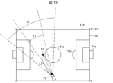
図13は、図11および図12における画角を比較して説明する図である。図13に示すように、本実施形態の具体例である視野画像G1(図11)は、画角r1のカメラ14により撮像された現実画像に、画角r3(r3<r1)に設定された仮想カメラにより撮像された仮想画像が重畳されたものである。これに対して、比較例である視野画像G9(図12)は、画角r1のカメラ14により撮像された現実画像に、同一の画角r1に設定された仮想カメラにより撮像された仮想画像が重畳されたものである。
Figure 13 is a diagram for explaining the angles of view in Figures 11 and 12 by comparison. As shown in Figure 13, field of view image G1 (Figure 11), which is a specific example of this embodiment, is obtained by superimposing a virtual image captured by a virtual camera set to an angle of view r3 (r3<r1) on a real image captured by
視野画像G1(図11)に含まれる選手キャラクタV2と、サッカーボールV3と、センターサークルを示すオブジェクトV1cは、視野画像G9(図12)に含まれるこれらのオブジェクトに比較してズームされている。このように、比較例では、ユーザが近づける操作を行っても、近づいた分だけしか選手キャラクタV2の表示サイズは大きくならない。これに対して、本実施形態に係る具体例では、ユーザが近づける操作を行うと、近づいた分以上に選手キャラクタV2の表示サイズが大きくなる。 The player character V2, soccer ball V3, and object V1c representing the center circle included in the field of view image G1 (Fig. 11) are zoomed in compared to these objects included in the field of view image G9 (Fig. 12). Thus, in the comparative example, even if the user performs an operation to bring the player character V2 closer, the display size of the player character V2 only increases by the amount of the movement. In contrast, in the specific example according to this embodiment, when the user performs an operation to bring the player character V2 closer, the display size of the player character V2 increases by more than the amount of the movement.
なお、視野画像G1では、現実画像を撮影したカメラ14の画角r1と、仮想画像を生成するために用いられるプロジェクション変換行列を算出する際のパラメータとして使われた画角r3とが異なっているため、本来の現実空間および仮想空間の位置関係が維持されない。例えば、マーカR2の円周に沿っていたはずのセンターサークルを示すオブジェクトV1cは、当該円周に沿っていない。ただし、現実空間および仮想空間の位置関係は、一旦維持されない状態となっても、その後、仮想カメラがフィールド領域Fから閾値L1以上遠ざかると再度整合する。また、ユーザは、選手キャラクタV2の表示操作を大きくするために、上述したような近づける操作を行うため、近づける操作に伴って近づけた分以上に選手キャラクタがズームされても違和感が少ない。このため、現実画像と仮想画像との位置関係が一時的に維持されない状態となっても、選手キャラクタV2の表示サイズが違和感なく大きくなることのメリットは大きい。
In the field of view image G1, the angle of view r1 of the
<本実施形態の効果>
このように、本実施形態によれば、ユーザが、仮想空間に配置された選手キャラクタの表示サイズを大きくするために、仮想カメラを選手キャラクタに近づけるよう情報処理装置10を動かす操作を行うと、仮想カメラの画角が狭くなる。このため、選手キャラクタの表示サイズは、仮想カメラが選手キャラクタに近づいた分以上に大きくなる。その結果、本実施形態は、AR技術によって実現されるサッカーゲームにおいて、選手キャラクタの視認性を向上させることができる。
<Effects of this embodiment>
Thus, according to this embodiment, when a user performs an operation of moving the
〔実施形態2〕
本発明の実施形態2に係る情報処理装置10Aについて、以下に説明する。情報処理装置10Aは、実施形態1に係る情報処理装置10と同様に、AR技術を用いてサッカーゲームを実現する装置である。なお、説明の便宜上、実施形態1にて説明した部材と同じ機能を有する部材については、同じ符号を付記し、その説明を繰り返さない。
[Embodiment 2]
An
<情報処理装置10Aの機能的な構成>
図14は、情報処理装置10Aの機能的な構成を示すブロック図である。なお、情報処理装置10Aの概要およびハードウェア構成の一例は、実施形態1において図1~図3を参照して説明した通りであるため、詳細な説明を繰り返さない。情報処理装置10Aは、配置部111と、変更部112Aと、表示部113と、AR制御部114と、ゲーム進行部115とを含む。
<Functional configuration of
Fig. 14 is a block diagram showing the functional configuration of
配置部111、表示部113、AR制御部114、およびゲーム進行部115の構成については、実施形態1で説明した通りであるため、詳細な説明を繰り返さない。
The configurations of the
変更部112Aは、現実空間でのカメラ14の動きに応じて、選手キャラクタV2の仮想空間におけるサイズを変更する。また、変更部112Aは、選手キャラクタV2が配置された領域に仮想カメラが近いほど、選手キャラクタの仮想空間におけるサイズを拡大する。なお、本実施形態でも、実施形態1と同様に、「選手キャラクタV2が配置された領域」として、フィールド領域Fを適用する。
The
以降、仮想カメラがフィールド領域Fに近いほど選手キャラクタV2の仮想空間におけるサイズを拡大する処理を、単に、サイズ変更処理とも記載する。サイズ変更処理には、距離Lが小さくなるにつれて選手キャラクタV2の仮想空間におけるサイズを拡大する処理が含まれる。また、サイズ変更処理には、距離Lが大きくなるにつれて選手キャラクタV2の仮想空間におけるサイズを縮小する処理が含まれる。 Hereinafter, the process of increasing the size of the player character V2 in the virtual space as the virtual camera gets closer to the field area F will be referred to simply as the size change process. The size change process includes a process of increasing the size of the player character V2 in the virtual space as the distance L gets smaller. The size change process also includes a process of reducing the size of the player character V2 in the virtual space as the distance L gets larger.
例えば、変更部112Aは、仮想空間に配置された複数の選手キャラクタV2のうち、少なくとも仮想カメラの画角の範囲に配置されている各選手キャラクタV2の仮想空間におけるサイズを変更してもよい。
For example, the
また、例えば、変更部112Aは、仮想空間に配置された複数の選手キャラクタV2のうち、特定の選手キャラクタV2の仮想空間におけるサイズを変更してもよい。特定の選手キャラクタV2とは、例えば、ユーザ操作(例えば、タップ操作)等により指定された選手キャラクタV2であってもよい。また、特定の選手キャラクタV2とは、仮想カメラの位置から撮像方向に伸びる直線上に配置されている選手キャラクタV2であってもよい。
Also, for example, the
また、変更部112Aは、仮想カメラと、当該仮想カメラから撮像方向に伸びる直線がフィールド領域Fに交わる交点との距離Lが小さいほど、選手キャラクタV2の仮想空間におけるサイズを拡大する。換言すると、変更部112Aは、仮想カメラから撮像方向に伸びる直線がフィールド領域Fに交わらない場合には、サイズ変更処理を行わない。なお、仮想カメラの位置P2から交点P3までの距離Lを算出する処理の詳細については、実施形態1において図5を参照して説明した通りであるため、詳細な説明を繰り返さない。
The
また、変更部112Aは、サイズ変更処理を、仮想カメラの位置P2と上述の交点P3との距離Lが閾値L1より大きい場合は実行せず、閾値L1以下の場合に実行する。また、変更部112Aは、サイズ変更処理を、仮想カメラと上述の交点P3との距離Lが、閾値L2(L2<L1)より小さい場合は実行しなくてもよい。この場合、換言すると、変更部112Aは、サイズ変更処理を、距離LがL2以上L1以下の範囲で実行する。
また、変更部112Aは、仮想カメラがフィールド領域Fに近づくにしたがって選手キャラクタV2の仮想空間におけるサイズを連続的に変化させる。この場合、変更部112Aは、該当する選手キャラクタV2について、仮想空間において定められたサイズに対する倍率を、距離L1に対する倍率n1(n1=1)から距離L2に対する倍率n2(n2>n1)まで連続的に(例えば、線形的に)変化させる。なお、仮想空間におけるサイズの連続的な変化は、線形変化であってもよいし、その他の変化であってもよい。例えば、変更部112Aは、仮想カメラがフィールド領域Fに近づくほど、上述した倍率の変化率を大きくしてもよい。
The
<情報処理装置10Aの動作>
以上のように構成された情報処理装置10の動作について説明する。図15は、情報処理装置10Aの動作を説明するフローチャートである。
<Operation of
The following describes the operation of the
ステップS100~S116まで、情報処理装置10Aは、実施形態1に係る情報処理装置10と同様に動作する。
From steps S100 to S116, the
ステップS118Aにおいて、変更部112Aは、サイズ変更条件が満たされるか否かを判断する。サイズ変更条件とは、ここでは、ステップS116で取得した距離Lが、閾値L1以下であり、かつ、閾値L2以上であるとの条件である。ステップS118AでNoの場合、後述するステップS122の処理が実行される。ステップS118AでYesの場合、次のステップS120Aの処理が実行される。
In step S118A, the
ステップS120Aにおいて、変更部112Aは、仮想カメラの位置P2と交点P3との距離Lが近いほど選手キャラクタV2の仮想空間におけるサイズを拡大するよう、サイズ変更処理を行う。なお、今回の処理フローにおいて取得された距離Lが、前回の処理フローにおいて取得された距離Lより小さい場合、仮想カメラは、前回よりもフィールド領域Fに近づいている。この場合、変更部112Aは、選手キャラクタV2の仮想空間におけるサイズを前回よりも拡大する。一方、今回の処理フローにおいて取得された距離Lが、前回の処理フローにおいて取得された距離Lより大きい場合、仮想カメラは、前回よりもフィールド領域Fから遠ざかっている。この場合、変更部112Aは、選手キャラクタV2の仮想空間におけるサイズを前回よりも小さくする。
In step S120A, the
ステップS122~S124まで、情報処理装置10Aは、実施形態1に係る情報処理装置10と同様に動作する。以上で、情報処理装置10Aの動作の説明を終了する。
From steps S122 to S124, the
<視野画像の一例>
図16は、表示装置17に表示される視野画像の一例を示す図である。図16に示す視野画像G1Aでは、少なくとも仮想カメラの画角の範囲に配置された各選手キャラクタV2について、仮想空間におけるサイズが拡大されている。図17は、表示装置17に表示される視野画像の他の一例を示す図である。図17に示す視野画像G1Bでは、特定の選手キャラクタV2について、仮想空間におけるサイズが拡大されている。
<Example of field of view image>
Fig. 16 is a diagram showing an example of a field of view image displayed on the
<本実施形態の効果>
本実施形態によれば、ユーザが、仮想空間に配置された選手キャラクタの表示サイズを大きくするために、仮想カメラを選手キャラクタに近づけるよう情報処理装置10を動かす操作を行うと、選手キャラクタの仮想空間におけるサイズが自動的に拡大される。このため、選手キャラクタの表示サイズは、仮想カメラが選手キャラクタに近づいた分以上に大きくなる。その結果、本実施形態は、AR技術によって実現されるサッカーゲームにおいて、選手キャラクタの視認性を向上させることができる。
<Effects of this embodiment>
According to this embodiment, when a user performs an operation of moving the
〔変形例1〕
上述した各実施形態では、サッカーを模したサッカーゲームを実現する例について説明した。ただし、各実施形態は、本発明における競技として、サッカーに限らず、他の競技を適用するよう変形可能である。他の競技の一例としては、例えば、野球、ラグビー等があるが、これに限られず、競技場で選手が移動して行われる競技であればよい。
[Modification 1]
In each of the above-mentioned embodiments, an example of implementing a soccer game simulating soccer has been described. However, each of the embodiments can be modified to apply other sports, not limited to soccer, as the sport in the present invention. Examples of other sports include baseball and rugby, but are not limited to these, and any sport in which players move around on a stadium may be used.
なお、他の競技としては、サッカーのように、フィールドサイズに対する選手身長の比率が相対的に小さい競技が好適である。 Other sports where the ratio of player height to field size is relatively small, such as soccer, are also suitable.
例えば、公益財団法人日本サッカー協会から発行された「サッカー競技規則2018/19」によれば、サッカーフィールドの長辺(タッチライン)の長さは90~120メートルである。選手の身長を約1~2.5メートルとすると、タッチラインの長さに対する比率は、約0.0083~0.0278である。これに対して、例えば、公益財団法人日本バスケットボール協会により発行された「2018バスケットボール競技規則」によれば、バスケットボールのコートの長辺(縦)の長さは28メートルである。選手の身長を約1~2.5メートルとすると、タッチラインの長さに対する比率は、約0.0357~0.0893である。このように、サッカーでは、バスケットボールに比較して、フィールドサイズに対する選手身長の比率が小さい。 For example, according to the "2018/19 Rules of the Game" issued by the Japan Football Association, the length of the long side (touchline) of a soccer field is 90 to 120 meters. If the height of a player is approximately 1 to 2.5 meters, the ratio to the length of the touchline is approximately 0.0083 to 0.0278. In contrast, according to the "2018 Rules of the Game" issued by the Japan Basketball Association, the length of the long side (vertical) of a basketball court is 28 meters. If the height of a player is approximately 1 to 2.5 meters, the ratio to the length of the touchline is approximately 0.0357 to 0.0893. Thus, in soccer, the ratio of player height to field size is smaller than in basketball.
これらの競技を模したゲームをそれぞれ実現する場合、仮想空間に配置するサッカーフィールドおよびバスケットボールのコートがほぼ同サイズであれば、サッカーゲームの選手キャラクタの仮想空間におけるサイズは、バスケットボールゲームの選手キャラクタより小さくなる。そのため、仮想カメラを選手キャラクタに十分に近づけても、各実施形態における画角変更処理またはサイズ変更処理を行わない場合、選手キャラクタの表示サイズは、サッカーゲームのほうがバスケットボールゲームより小さくなり、視認性が良くない。 When games simulating these sports are realized, if the soccer field and basketball court placed in the virtual space are approximately the same size, the size of the player characters in the soccer game in the virtual space will be smaller than the player characters in the basketball game. Therefore, even if the virtual camera is brought close enough to the player characters, if the angle of view change process or size change process in each embodiment is not performed, the display size of the player characters in the soccer game will be smaller than that of the basketball game, and visibility will be poor.
上述したように、一例としてバスケットボールを基準とすれば、サッカー、野球、ラグビー等の競技は、フィールドサイズに対する選手身長の比率が相対的に小さい競技である。フィールドサイズに対する選手身長の比率が相対的に小さい競技を模したゲームでは、選手キャラクタV2の表示サイズは、仮想カメラが近づいた分相応に大きくなるだけでは、ユーザの視認性の観点から十分なサイズと言えない場合が多い。 As mentioned above, if we take basketball as an example, sports such as soccer, baseball, and rugby are sports in which the ratio of player height to field size is relatively small. In games that mimic sports in which the ratio of player height to field size is relatively small, the display size of the player character V2 is often not sufficient from the perspective of user visibility if it is simply increased in proportion to the virtual camera's proximity.
本変形例は、画角変更処理またはサイズ変更処理を行うことにより、フィールドサイズに対する選手身長の比率が相対的に小さいゲームであっても、選手キャラクタの視認性を向上することができる。 By performing angle of view change processing or size change processing, this modified example can improve the visibility of player characters even in games where the ratio of player height to field size is relatively small.
〔変形例2〕
各実施形態において、変更部112および変更部112Aは、画角または選手キャラクタV2の仮想空間におけるサイズを連続的に変化させる例について説明した。これに限らず、変更部112および変更部112Aは、画角または選手キャラクタV2の仮想空間におけるサイズを段階的に変化させてもよい。例えば、変更部112は、距離Lが閾値L1より大きい場合は、AR制御部114から取得した画角r1を適用し、距離Lが閾値L1以下の場合は、予め設定された画角r4(r4<r1)を適用してもよい。また、例えば、変更部112Aは、選手キャラクタに予め定められたサイズに対して、距離Lが閾値L1より大きい場合は倍率n1=1を適用し、距離Lが閾値L1以下の場合は予め設定された倍率n2(n2>n1)を適用してもよい。
[Modification 2]
In each embodiment, the
〔変形例3〕
各実施形態において、変更部112および変更部112Aは、フィールド領域Fに仮想カメラが近いほど、仮想カメラの画角を狭くする処理またはサイズ変更処理を行う例について説明した。これに限らず、変更部112および変更部112Aは、画角を狭くする処理またはサイズ変更処理を、仮想カメラが、選手キャラクタが仮想空間において競技を行う仮想的な競技場を含む所定領域の外部にある場合には実行せず、内部にある場合に実行してもよい。
[Modification 3]
In each embodiment, an example has been described in which the
ここで、所定領域とは、フィールド領域Fを含む平面領域であってもよい。具体的には、そのような所定領域は、フィールド領域Fの四辺を所定マージン分だけ拡大した矩形の領域であってもよいし、フィールド領域Fを含む略楕円形の領域であってもよい。 Here, the specified area may be a planar area including the field area F. Specifically, such a specified area may be a rectangular area in which the four sides of the field area F are expanded by a specified margin, or may be a substantially elliptical area including the field area F.
また、所定領域とは、フィールド領域Fを含む平面を底面とする三次元空間領域であってもよい。具体的には、そのような所定領域は、フィールド領域Fを底面に含む略半球状の空間領域であってもよいし、フィールド領域Fを底面に含む略直方体状の空間領域であってもよい。 The specified area may also be a three-dimensional spatial area having a plane including the field area F as its bottom surface. Specifically, such a specified area may be a substantially hemispherical spatial area having the field area F as its bottom surface, or may be a substantially rectangular parallelepiped spatial area having the field area F as its bottom surface.
本変形例では、選手キャラクタV2の表示サイズが、情報処理装置10(すなわちカメラ14)を近づけた分以上に大きくなるのは、仮想カメラが所定領域の内部にある場合に限られる。また、仮想カメラが所定領域の外部にある場合では、選手キャラクタV2は、距離相応の表示サイズで表示される。このため、ユーザにとって、表示サイズの変化がより自然なものとなる。 In this modified example, the display size of the player character V2 increases by more than the distance the information processing device 10 (i.e., the camera 14) is brought closer only when the virtual camera is inside the specified area. Also, when the virtual camera is outside the specified area, the player character V2 is displayed at a display size appropriate to the distance. This makes the change in display size more natural to the user.
〔その他の変形例〕
各実施形態において、情報処理装置10が備えるカメラ14が単焦点レンズを備える例について説明した。これに限らず、各実施形態は、カメラ14がズームレンズを備えるよう変形可能である。このような構成では、カメラ14の画角は変化する。この場合、AR制御部114は、仮想カメラの画角を、カメラ14の画角の変化に連動させて設定する。なお、この場合でも、実施形態1における変更部112は、カメラ14の画角の変化に連動してAR制御部114によって設定された仮想カメラの画角を取得して、取得した画角を変更すればよい。
[Other Modifications]
In each embodiment, an example has been described in which the
また、実施形態1において、カメラ14および仮想カメラの各画角が異なることに起因して、現実空間および仮想空間の位置関係が一時的に維持されない状態となることについて説明した。ただし、実施形態1は、仮想カメラの画角の変更に連動させてカメラ14の画角を変更するよう変形可能である。これにより、現実空間および仮想空間の位置関係が維持される。つまり、本変形例では、変更部112は、仮想カメラがフィールド領域Fに近いほど仮想カメラの画角を狭くするよう画角変更処理を実行するとともに、カメラ14の画角を、変更した仮想カメラの画角と同一の値に変更する。なお、この場合、情報処理装置10は、カメラ14の画角を、ユーザ操作によらずに制御する画角制御機能を備えているものとする。もし、カメラ14がズームレンズを備えている場合、画角制御機能により、ズームレンズの画角を変更するようカメラ14が制御される。また、カメラ14が単焦点レンズを備えている場合、画角制御機能により、カメラ14の画角を疑似的に変更した撮像画像を生成する処理が実行される。
In addition, in the first embodiment, it has been described that the positional relationship between the real space and the virtual space is temporarily not maintained due to the difference in the angles of view of the
また、各実施形態において、表示部113は、不明瞭に加工した現実画像に、仮想画像を重畳するよう変形可能である。これにより、表示装置17に表示される仮想現実空間の視野画像は、仮想画像の背景である現実画像がぼやけた画像となる。これにより、実施形態1では、仮想画像と現実画像との画角が異なることにより合成される視野画像からユーザが受ける違和感を、さらに軽減することができる。また、実施形態2では、選手キャラクタのサイズが拡大された視野画像からユーザが受ける違和感を軽減することができる。
In addition, in each embodiment, the
また、各実施形態において、配置部111は、複数の選手キャラクタV2を仮想空間に配置する例について説明した。ただし、配置される選手キャラクタV2の数は、競技に応じて、複数に限らず1つであってもよい。
In each embodiment, an example has been described in which the
〔まとめ〕
以上に例示した形態から、例えば以下の構成が把握される。なお、各態様の理解を容易にするために、以下では、図面の参照符号を便宜的に括弧書で付記するが、本発明を図示の態様に限定する趣旨ではない。
〔summary〕
From the above-described exemplary embodiments, the following configurations can be understood. Note that, in order to facilitate understanding of each embodiment, reference numerals in the drawings are conveniently placed in parentheses below, but this is not intended to limit the present invention to the embodiments shown in the drawings.
本発明の一態様に係るゲームプログラムは、競技を模したゲームを実現するために、撮像装置(14)と表示装置(17)とを含むコンピュータに、現実空間との位置関係が規定された仮想空間であって、前記現実空間での前記撮像装置(14)の位置に対応する前記仮想空間での位置に仮想カメラが配置される仮想空間に、選手キャラクタ(V2)を配置する配置ステップ(S112)と、前記現実空間での前記撮像装置(14)の動きに応じて、前記仮想カメラの画角を変更する変更ステップ(S120)と、前記仮想空間が前記仮想カメラによって撮影される仮想画像を、前記現実空間が前記撮像装置(14)によって撮像される現実画像に重畳して前記表示装置(17)に表示する表示ステップ(S122)と、を実行させ、前記変更ステップ(S120)では、前記選手キャラクタ(V2)が配置された領域に前記仮想カメラが近いほど、前記仮想カメラの画角を狭くする。 In one aspect of the present invention, a game program causes a computer including an imaging device (14) and a display device (17) to execute a placement step (S112) of placing a player character (V2) in a virtual space in which a positional relationship with a real space is defined, in which a virtual camera is placed at a position in the virtual space corresponding to the position of the imaging device (14) in the real space, a change step (S120) of changing the angle of view of the virtual camera in accordance with the movement of the imaging device (14) in the real space, and a display step (S122) of superimposing a virtual image of the virtual space captured by the virtual camera on a real image of the real space captured by the imaging device (14) and displaying it on the display device (17), in order to realize a game simulating a competition. In the change step (S120), the angle of view of the virtual camera is narrowed as the virtual camera is closer to the area in which the player character (V2) is placed.
ここで、ユーザは、選手キャラクタの表示サイズを大きくしたいときには、仮想カメラが選手キャラクタに近づくように撮像装置を動かす。上記構成では、このようなユーザの操作(以降、撮像装置を近づける操作、等とも記載)に伴って、当該選手キャラクタが自動的にズームされる。これにより、近づけた分以上に選手キャラクタの表示サイズが大きくなるので、選手キャラクタの視認性が向上する。 When the user wishes to increase the display size of the player character, the user moves the imaging device so that the virtual camera moves closer to the player character. In the above configuration, the player character is automatically zoomed in in response to such a user operation (hereinafter also referred to as an operation to move the imaging device closer, etc.). This increases the display size of the player character by more than the amount of movement closer, improving the visibility of the player character.
特に、競技場サイズに対する選手サイズの比率が小さいサッカー等の競技を模したゲームの場合、近づけた分しか大きくならない表示サイズでは視認性の観点で不十分なことが多いため、上記構成は効果的である。また、ユーザは、選手キャラクタの表示サイズを少しでも大きくするために撮像装置を近づける操作を行うので、近づける操作に伴って選手キャラクタが自動的にズームされても違和感が少ない。 The above configuration is particularly effective in games that mimic sports such as soccer, where the ratio of player size to the size of the stadium is small, because a display size that only increases as the player moves closer is often insufficient in terms of visibility. Also, since the user moves the imaging device closer to increase the display size of the player character even slightly, there is little sense of incongruity even if the player character is automatically zoomed in as the user moves closer.
上述したゲームプログラムは、前記コンピュータに、前記現実空間および前記仮想空間との位置関係に整合するように前記仮想画像を前記現実画像に重畳するための前記仮想カメラの画角を取得する取得ステップ(S116)をさらに実行させ、前記変更ステップ(S120)は、前記取得ステップ(S116)で取得された画角を変更する、ことが好ましい。 The above-mentioned game program preferably further causes the computer to execute an acquisition step (S116) of acquiring an angle of view of the virtual camera for superimposing the virtual image on the real image so as to match the positional relationship between the real space and the virtual space, and the change step (S120) changes the angle of view acquired in the acquisition step (S116).
上記構成により、当該ゲームプログラムをコンピュータに実行させる際に、現実空間および前記仮想空間との位置関係に整合するように仮想画像を現実画像に重畳するための仮想カメラの画角を設定する公知の技術を用いることができる。その結果、当該ゲームプログラムの移植性および再利用性を高めることができる。 With the above configuration, when the game program is executed by a computer, a known technique can be used to set the angle of view of a virtual camera for superimposing a virtual image on a real image so as to match the positional relationship between the real space and the virtual space. As a result, the portability and reusability of the game program can be improved.
上述したゲームプログラムにおいて、前記変更ステップ(S120)は、前記仮想カメラと、当該仮想カメラから撮像方向に伸びる直線が前記領域に交わる交点との距離が小さいほど、前記仮想カメラの画角を狭くする、ことが好ましい。 In the game program described above, the change step (S120) preferably narrows the angle of view of the virtual camera as the distance between the virtual camera and the intersection point where a straight line extending from the virtual camera in the imaging direction intersects with the area becomes smaller.
上記構成により、仮想カメラと上述の交点との距離を参照することによって、上述した効果を奏するゲームを実現できる。 With the above configuration, a game that achieves the above-mentioned effects can be realized by referencing the distance between the virtual camera and the above-mentioned intersection.
上述したゲームプログラムにおいて、前記変更ステップ(S120)は、前記画角を狭くする処理を、前記距離が閾値より大きい場合は実行せず、前記閾値以下の場合に実行する、ことが好ましい。 In the game program described above, it is preferable that the change step (S120) does not narrow the angle of view when the distance is greater than a threshold value, but narrows the angle of view when the distance is equal to or less than the threshold value.
上記構成により、選手キャラクタの表示サイズが撮像装置を近づけた分以上に大きくなるのは、選手キャラクタが配置された領域に撮像装置を閾値以下の距離まで近づけた場合に限られ、閾値より離れている場合には距離相応の表示サイズで表示される。このため、ユーザにとって、表示サイズの変化がより自然なものとなる。 With the above configuration, the display size of the player character only becomes larger than the distance the imaging device is brought closer to when the imaging device is brought closer to the area in which the player character is located to a distance equal to or less than the threshold value. If the imaging device is farther away than the threshold value, the player character is displayed at a display size appropriate to the distance. This makes the change in display size seem more natural to the user.
上述したゲームプログラムにおいて、前記変更ステップ(S120)は、前記画角を狭くする処理を、前記仮想カメラが、前記選手キャラクタ(V2)が前記仮想空間において競技を行う仮想的な競技場を含む所定領域の外部にある場合には実行せず、内部にある場合に実行する、ことが好ましい。 In the above-mentioned game program, it is preferable that the change step (S120) does not execute the process of narrowing the angle of view when the virtual camera is outside a predetermined area including a virtual stadium where the player character (V2) competes in the virtual space, but executes the process when the virtual camera is inside the predetermined area.
上記構成により、選手キャラクタの表示サイズが撮像装置を近づけた分以上に大きくなるのは、仮想カメラが所定領域の内部にある場合に限られ、その外部にある場合では距離相応の表示サイズで表示される。このため、ユーザにとって、表示サイズの変化がより自然なものとなる。 With the above configuration, the display size of the player character only becomes larger when the virtual camera is inside a specified area, and when it is outside the area, it is displayed at a size appropriate to the distance. This makes the change in display size more natural to the user.
上述したゲームプログラムにおいて、前記変更ステップ(S120)は、前記仮想カメラが前記領域に近づくにしたがって前記画角を連続的に変化させる、ことが好ましい。 In the above-mentioned game program, it is preferable that the change step (S120) continuously changes the angle of view as the virtual camera approaches the area.
上記構成により、ユーザは、撮像装置を近づける程度を調整することにより、好みの表示サイズで選手キャラクタを表示させることができる。 With the above configuration, the user can display the player character at the display size of their choice by adjusting how close the imaging device is to the screen.
上述したゲームプログラムにおいて、前記変更ステップ(S120)は、前記仮想カメラが前記領域に近づくほど前記画角の変化率を大きくする、ことが好ましい。 In the game program described above, it is preferable that the change step (S120) increases the rate of change of the angle of view as the virtual camera approaches the area.
上記構成により、ユーザは、撮像装置を選手キャラクタに近づけるほど、より急激に選手キャラクタの表示サイズを大きくすることができる。 With the above configuration, the user can increase the display size of the player character more dramatically the closer the imaging device is to the player character.
本発明の他の一態様に係るゲームプログラムは、競技を模したゲームを実現するために、撮像装置(14)と表示装置(17)とを含むコンピュータに、現実空間との位置関係が規定された仮想空間であって、前記現実空間での前記撮像装置(14)の位置に対応する前記仮想空間での位置に仮想カメラが配置される仮想空間に、選手キャラクタ(V2)を配置する配置ステップ(S112)と、前記現実空間での前記撮像装置(14)の動きに応じて、前記選手キャラクタ(V2)の前記仮想空間におけるサイズを変更する変更ステップ(S120)と、前記仮想空間が前記仮想カメラによって撮影される仮想画像を、前記現実空間が前記撮像装置(14)によって撮像される現実画像に重畳して前記表示装置(17)に表示する表示ステップ(S122)と、を実行させ、前記変更ステップ(S120)は、前記選手キャラクタ(V2)が配置された領域に前記仮想カメラが近いほど、前記選手キャラクタ(V2)の前記仮想空間におけるサイズを拡大する。 In another aspect of the present invention, a game program for implementing a game simulating a competition causes a computer including an imaging device (14) and a display device (17) to execute a placement step (S112) of placing a player character (V2) in a virtual space in which a positional relationship with a real space is defined, in which a virtual camera is placed at a position in the virtual space corresponding to the position of the imaging device (14) in the real space, a modification step (S120) of changing the size of the player character (V2) in the virtual space according to the movement of the imaging device (14) in the real space, and a display step (S122) of displaying on the display device (17) a virtual image of the virtual space captured by the virtual camera superimposed on a real image of the real space captured by the imaging device (14), and the modification step (S120) increases the size of the player character (V2) in the virtual space the closer the virtual camera is to the area in which the player character (V2) is placed.
上記構成により、ユーザが撮像装置を選手キャラクタに近づける操作に伴って、当該選手キャラクタが自動的に拡大される。これにより、選手キャラクタの表示サイズを近づけた分以上に大きくすることができるので、選手キャラクタの視認性が向上する。 With the above configuration, when the user moves the imaging device closer to the player character, the player character is automatically enlarged. This allows the display size of the player character to be enlarged by more than the amount of the approach, improving the visibility of the player character.
本発明の一態様に係る情報処理装置は、競技を模したゲームを実現するための、撮像装置(14)と表示装置(17)とを含む情報処理装置であって、現実空間との位置関係が規定された仮想空間であって、前記現実空間での前記撮像装置(14)の位置に対応する前記仮想空間での位置に仮想カメラが配置される仮想空間に、選手キャラクタ(V2)を配置する配置部と、前記現実空間での前記撮像装置(14)の動きに応じて、前記仮想カメラの画角を変更する変更部と、前記仮想空間が前記仮想カメラによって撮影される仮想画像を、前記現実空間が前記撮像装置(14)によって撮像される現実画像に重畳して前記表示装置(17)に表示する表示部と、を含み、前記変更部は、前記選手キャラクタ(V2)が配置された領域に前記仮想カメラが近いほど、前記仮想カメラの画角を狭くする。 An information processing device according to one aspect of the present invention is an information processing device including an imaging device (14) and a display device (17) for realizing a game simulating a competition, and includes: a placement unit that places a player character (V2) in a virtual space in which a positional relationship with a real space is defined, in which a virtual camera is placed at a position in the virtual space corresponding to the position of the imaging device (14) in the real space; a modification unit that changes the angle of view of the virtual camera according to the movement of the imaging device (14) in the real space; and a display unit that displays on the display device (17) a virtual image of the virtual space captured by the virtual camera superimposed on a real image of the real space captured by the imaging device (14), and the modification unit narrows the angle of view of the virtual camera the closer the virtual camera is to the area in which the player character (V2) is placed.
上記構成により、上述したゲームプログラムと同等の効果を奏する。 The above configuration achieves the same effect as the game program described above.
本発明の一態様に係る方法は、撮像装置(14)と表示装置(17)とを含むコンピュータが、競技を模したゲームを実現するために、現実空間との位置関係が規定された仮想空間であって、前記現実空間での前記撮像装置(14)の位置に対応する前記仮想空間での位置に仮想カメラが配置される仮想空間に、選手キャラクタ(V2)を配置する配置ステップ(S112)と、前記現実空間での前記撮像装置(14)の動きに応じて、前記仮想カメラの画角を変更する変更ステップ(S120)と、前記仮想空間が前記仮想カメラによって撮影される仮想画像を、前記現実空間が前記撮像装置(14)によって撮像される現実画像に重畳して前記表示装置(17)に表示する表示ステップ(S122)と、を実行し、前記変更ステップ(S120)は、前記選手キャラクタ(V2)が配置された領域に前記仮想カメラが近いほど、前記仮想カメラの画角を狭くする。 In a method according to one aspect of the present invention, a computer including an imaging device (14) and a display device (17) executes a placement step (S112) of placing a player character (V2) in a virtual space in which a positional relationship with a real space is defined in order to realize a game simulating a competition, in which a virtual camera is placed at a position in the virtual space corresponding to the position of the imaging device (14) in the real space, a change step (S120) of changing the angle of view of the virtual camera in accordance with the movement of the imaging device (14) in the real space, and a display step (S122) of superimposing a virtual image of the virtual space captured by the virtual camera on a real image of the real space captured by the imaging device (14) and displaying it on the display device (17), and the change step (S120) narrows the angle of view of the virtual camera as the virtual camera approaches the area in which the player character (V2) is placed.
上記構成により、上述したゲームプログラムと同等の効果を奏する。 The above configuration achieves the same effect as the game program described above.
〔ソフトウェアまたはハードウェアによる実現例〕
上述した実施形態および各変形例では、情報処理装置10の制御部110が、ソフトウェアにより実現される例について説明した。すなわち、本発明の目的を達成するためにコンピュータによって実行されるプログラムが、図2に示したコンピュータの補助メモリ13に記憶され、プロセッサ11が当該プログラムを読み取って実行することにより、情報処理装置10の制御部110が実現される。
[Software or hardware implementation examples]
In the above-described embodiment and each modified example, an example has been described in which the control unit 110 of the
なお、この場合、上記プログラムを記憶する補助メモリ13としては、「一時的でない有形の媒体」、例えば、ROM(Read Only Memory)等の他、テープ、ディスク、カード、半導体メモリ、プログラマブルな論理回路などを用いることができる。
In this case, the
また、上記プログラムは、該プログラムを伝送可能な任意の伝送媒体(通信ネットワークや放送波等)を介して上記コンピュータに供給されてもよい。また、本発明の一態様は、上記プログラムが電子的な伝送によって具現化された、搬送波に埋め込まれたデータ信号の形態でも実現され得る。 The program may be supplied to the computer via any transmission medium capable of transmitting the program (such as a communications network or broadcast waves). Another aspect of the present invention may be realized in the form of a data signal embedded in a carrier wave, in which the program is embodied by electronic transmission.
なお、情報処理装置10の制御部110は、ソフトウェアによる実現に限らず、集積回路(ICチップ)等に形成された論理回路(ハードウェア)によって実現されてもよい。
The control unit 110 of the
本発明は上述した各実施形態に限定されるものではなく、請求項に示した範囲で種々の変更が可能であり、異なる実施形態にそれぞれ開示された技術的手段を適宜組み合わせて得られる実施形態についても本発明の技術的範囲に含まれる。 The present invention is not limited to the above-described embodiments, and various modifications are possible within the scope of the claims. The technical scope of the present invention also includes embodiments obtained by appropriately combining the technical means disclosed in different embodiments.
10、10A 情報処理装置
11 プロセッサ
12 主メモリ
13 補助メモリ
14 カメラ
15 タッチパネル
16 位置センサ
17 表示装置
18 入力装置
110 制御部
111 配置部
112、112A 変更部
113 表示部
114 AR制御部
115 ゲーム進行部
REFERENCE SIGNS
Claims (7)
現実空間との位置関係が規定された前記仮想空間であって、前記現実空間での前記撮像装置の位置に対応する前記仮想空間での位置に仮想カメラが配置される前記仮想空間のゲームフィールドに、キャラクタオブジェクトを配置する配置ステップと、
前記現実空間での前記撮像装置の動きに応じて、前記仮想カメラの画角を変更する変更ステップと、
前記仮想空間が前記仮想カメラによって撮影される仮想画像を、前記現実空間が前記撮像装置によって撮像される現実画像に重畳して前記表示装置に表示する表示ステップと、を実行させ、
前記変更ステップでは、前記キャラクタオブジェクトが配置された前記ゲームフィールドに前記仮想カメラが近いほど、前記仮想カメラの画角を狭くする、ゲームプログラム。 In order to realize a game in which a character object is placed in a game field in a virtual space, a computer including an imaging device and a display device is provided with:
a placement step of placing a character object in a game field of the virtual space, the virtual space having a positional relationship with a real space defined, the virtual camera being placed at a position in the virtual space corresponding to a position of the imaging device in the real space;
a changing step of changing an angle of view of the virtual camera in response to a movement of the imaging device in the real space;
a display step of displaying, on the display device, a virtual image of the virtual space captured by the virtual camera, superimposed on a real image of the real space captured by the imaging device;
The changing step narrows the angle of view of the virtual camera as the virtual camera is closer to the game field on which the character object is placed.
前記現実空間および前記仮想空間との位置関係に整合するように前記仮想画像を前記現実画像に重畳するための前記仮想カメラの画角を取得する取得ステップをさらに実行させ、
前記変更ステップは、前記取得ステップで取得された画角を変更する、
請求項1に記載のゲームプログラム。 The computer includes:
acquiring an angle of view of the virtual camera for superimposing the virtual image on the real image so as to match a positional relationship between the real space and the virtual space;
The changing step changes the angle of view acquired in the acquiring step.
The game program according to claim 1 .
現実空間との位置関係が規定された前記仮想空間であって、前記現実空間での前記撮像装置の位置に対応する前記仮想空間での位置に仮想カメラが配置される前記仮想空間のゲームフィールドに、キャラクタオブジェクトを配置する配置ステップと、
前記現実空間での前記撮像装置の動きに応じて、前記キャラクタオブジェクトの前記仮想空間におけるサイズを変更する変更ステップと、
前記仮想空間が前記仮想カメラによって撮影される仮想画像を、前記現実空間が前記撮像装置によって撮像される現実画像に重畳して前記表示装置に表示する表示ステップと、
を実行させ、
前記変更ステップは、前記キャラクタオブジェクトが配置された前記ゲームフィールドに前記仮想カメラが近いほど、前記キャラクタオブジェクトの前記仮想空間におけるサイズを拡大する、ゲームプログラム。 In order to realize a game in which a character object is placed in a game field in a virtual space, a computer including an imaging device and a display device is provided with:
a placement step of placing a character object in a game field of the virtual space, the virtual space having a positional relationship with a real space defined, the virtual camera being placed at a position in the virtual space corresponding to a position of the imaging device in the real space;
a changing step of changing a size of the character object in the virtual space in response to a movement of the imaging device in the real space;
a display step of displaying, on the display device, a virtual image of the virtual space captured by the virtual camera, superimposed on a real image of the real space captured by the imaging device;
Run the command,
The change step increases a size of the character object in the virtual space as the virtual camera approaches the game field on which the character object is placed.
現実空間との位置関係が規定された前記仮想空間であって、前記現実空間での前記撮像装置の位置に対応する前記仮想空間での位置に仮想カメラが配置される仮想空間に、前記キャラクタオブジェクトを配置する配置部と、
前記現実空間での前記撮像装置の動きに応じて、前記仮想カメラの画角を変更する変更部と、
前記仮想空間が前記仮想カメラによって撮影される仮想画像を、前記現実空間が前記撮像装置によって撮像される現実画像に重畳して前記表示装置に表示する表示部と、を含み、
前記変更部は、前記キャラクタオブジェクトが配置された前記ゲームフィールドに前記仮想カメラが近いほど、前記仮想カメラの画角を狭くする、情報処理装置。 An information processing device including an imaging device and a display device for realizing a game in which a character object is placed on a game field in a virtual space,
a placement unit that places the character object in the virtual space, the virtual space having a positional relationship with a real space defined, and a virtual camera is placed at a position in the virtual space corresponding to a position of the imaging device in the real space;
a change unit that changes an angle of view of the virtual camera in response to a movement of the imaging device in the real space;
a display unit that displays, on the display device, a virtual image of the virtual space captured by the virtual camera, superimposed on a real image of the real space captured by the imaging device,
The change unit narrows the angle of view of the virtual camera as the virtual camera is closer to the game field on which the character object is placed.
仮想空間のゲームフィールドにキャラクタオブジェクトが配置されるゲームを実現するために、
現実空間との位置関係が規定された前記仮想空間であって、前記現実空間での前記撮像装置の位置に対応する前記仮想空間での位置に仮想カメラが配置される仮想空間に、前記キャラクタオブジェクトを配置する配置ステップと、
前記現実空間での前記撮像装置の動きに応じて、前記仮想カメラの画角を変更する変更ステップと、
前記仮想空間が前記仮想カメラによって撮影される仮想画像を、前記現実空間が前記撮像装置によって撮像される現実画像に重畳して前記表示装置に表示する表示ステップと、を実行し、
前記変更ステップは、前記キャラクタオブジェクトが配置された前記ゲームフィールドに前記仮想カメラが近いほど、前記仮想カメラの画角を狭くする、方法。 A computer including an imaging device and a display device,
In order to realize a game in which a character object is placed on a game field in a virtual space,
a placement step of placing the character object in the virtual space, the virtual space having a positional relationship with a real space defined, the virtual space having a virtual camera placed at a position in the virtual space corresponding to a position of the imaging device in the real space;
a changing step of changing an angle of view of the virtual camera in response to a movement of the imaging device in the real space;
a display step of displaying, on the display device, a virtual image of the virtual space captured by the virtual camera, superimposed on a real image of the real space captured by the imaging device;
The changing step narrows the angle of view of the virtual camera as the virtual camera is closer to the game field on which the character object is placed.
Priority Applications (1)
| Application Number | Priority Date | Filing Date | Title |
|---|---|---|---|
| JP2023175894A JP7602829B2 (en) | 2019-11-08 | 2023-10-11 | Game program, information processing device, and method |
Applications Claiming Priority (2)
| Application Number | Priority Date | Filing Date | Title |
|---|---|---|---|
| JP2019203502A JP7371901B2 (en) | 2019-11-08 | 2019-11-08 | Game program, information processing device, and method |
| JP2023175894A JP7602829B2 (en) | 2019-11-08 | 2023-10-11 | Game program, information processing device, and method |
Related Parent Applications (1)
| Application Number | Title | Priority Date | Filing Date |
|---|---|---|---|
| JP2019203502A Division JP7371901B2 (en) | 2019-11-08 | 2019-11-08 | Game program, information processing device, and method |
Publications (2)
| Publication Number | Publication Date |
|---|---|
| JP2023182760A JP2023182760A (en) | 2023-12-26 |
| JP7602829B2 true JP7602829B2 (en) | 2024-12-19 |
Family
ID=75899627
Family Applications (2)
| Application Number | Title | Priority Date | Filing Date |
|---|---|---|---|
| JP2019203502A Active JP7371901B2 (en) | 2019-11-08 | 2019-11-08 | Game program, information processing device, and method |
| JP2023175894A Active JP7602829B2 (en) | 2019-11-08 | 2023-10-11 | Game program, information processing device, and method |
Family Applications Before (1)
| Application Number | Title | Priority Date | Filing Date |
|---|---|---|---|
| JP2019203502A Active JP7371901B2 (en) | 2019-11-08 | 2019-11-08 | Game program, information processing device, and method |
Country Status (1)
| Country | Link |
|---|---|
| JP (2) | JP7371901B2 (en) |
Families Citing this family (4)
| Publication number | Priority date | Publication date | Assignee | Title |
|---|---|---|---|---|
| CN114979708B (en) * | 2022-05-20 | 2023-10-17 | 咪咕数字传媒有限公司 | Video push method, device, server equipment and readable storage medium |
| CN114995642B (en) * | 2022-05-27 | 2025-07-25 | 北京河图联合创新科技有限公司 | Augmented reality-based exercise training method and device, server and terminal equipment |
| CN115400428B (en) * | 2022-08-26 | 2025-05-13 | 上海网之易璀璨网络科技有限公司 | Game display control method, device, terminal equipment and storage medium |
| JP7476372B1 (en) * | 2023-02-07 | 2024-04-30 | 株式会社バンダイ | PROGRAM, INFORMATION PROCESSING DEVICE AND MATCHING SYSTEM |
Citations (7)
| Publication number | Priority date | Publication date | Assignee | Title |
|---|---|---|---|---|
| JP2001353358A (en) | 2000-06-14 | 2001-12-25 | Namco Ltd | Game device and information storage medium |
| JP2011154574A (en) | 2010-01-27 | 2011-08-11 | Namco Bandai Games Inc | Program, information storage medium, and game system |
| JP2011215920A (en) | 2010-03-31 | 2011-10-27 | Namco Bandai Games Inc | Program, information storage medium and image generation system |
| JP2011258152A (en) | 2010-06-11 | 2011-12-22 | Nintendo Co Ltd | Information processing program, information processor, information processing system and information processing method |
| JP2012068964A (en) | 2010-09-24 | 2012-04-05 | Nintendo Co Ltd | Image processing program, image processor, image processing system and image processing method |
| JP6407460B1 (en) | 2018-02-16 | 2018-10-17 | キヤノン株式会社 | Image processing apparatus, image processing method, and program |
| JP2020129272A (en) | 2019-02-08 | 2020-08-27 | 株式会社バンダイナムコエンターテインメント | Program and electronics |
Family Cites Families (1)
| Publication number | Priority date | Publication date | Assignee | Title |
|---|---|---|---|---|
| JP7034666B2 (en) * | 2016-12-27 | 2022-03-14 | キヤノン株式会社 | Virtual viewpoint image generator, generation method and program |
-
2019
- 2019-11-08 JP JP2019203502A patent/JP7371901B2/en active Active
-
2023
- 2023-10-11 JP JP2023175894A patent/JP7602829B2/en active Active
Patent Citations (7)
| Publication number | Priority date | Publication date | Assignee | Title |
|---|---|---|---|---|
| JP2001353358A (en) | 2000-06-14 | 2001-12-25 | Namco Ltd | Game device and information storage medium |
| JP2011154574A (en) | 2010-01-27 | 2011-08-11 | Namco Bandai Games Inc | Program, information storage medium, and game system |
| JP2011215920A (en) | 2010-03-31 | 2011-10-27 | Namco Bandai Games Inc | Program, information storage medium and image generation system |
| JP2011258152A (en) | 2010-06-11 | 2011-12-22 | Nintendo Co Ltd | Information processing program, information processor, information processing system and information processing method |
| JP2012068964A (en) | 2010-09-24 | 2012-04-05 | Nintendo Co Ltd | Image processing program, image processor, image processing system and image processing method |
| JP6407460B1 (en) | 2018-02-16 | 2018-10-17 | キヤノン株式会社 | Image processing apparatus, image processing method, and program |
| JP2020129272A (en) | 2019-02-08 | 2020-08-27 | 株式会社バンダイナムコエンターテインメント | Program and electronics |
Also Published As
| Publication number | Publication date |
|---|---|
| JP2023182760A (en) | 2023-12-26 |
| JP2021074277A (en) | 2021-05-20 |
| JP7371901B2 (en) | 2023-10-31 |
Similar Documents
| Publication | Publication Date | Title |
|---|---|---|
| JP7602829B2 (en) | Game program, information processing device, and method | |
| CN100536970C (en) | Game image display control program, game device, and recording medium | |
| JP5718197B2 (en) | Program and game device | |
| CN1640519B (en) | Image processing device and image processing method | |
| TW527201B (en) | An image generating device, an image generating method, a readable storage medium storing an image generating program and a video game system | |
| US20090244064A1 (en) | Program, information storage medium, and image generation system | |
| JP5819686B2 (en) | Programs and electronic devices | |
| US20090058856A1 (en) | Image generating apparatus, method of generating image, program, and recording medium | |
| US20170352188A1 (en) | Support Based 3D Navigation | |
| JP3833445B2 (en) | GAME DEVICE AND INFORMATION STORAGE MEDIUM | |
| JP7690301B2 (en) | Information processing device, system including the same, information processing method, and program | |
| JPH11235466A (en) | Computer game equipment | |
| JP5474899B2 (en) | PROGRAM, INFORMATION STORAGE MEDIUM, AND GAME DEVICE | |
| JP7492199B2 (en) | Game device and program | |
| JPH07178242A (en) | Viewpoint change method in ball game on game console | |
| JP4377114B2 (en) | Information storage medium and game device | |
| JP5911628B2 (en) | Game program | |
| JP6567325B2 (en) | Game program | |
| JP2006061717A (en) | GAME IMAGE DISPLAY CONTROL PROGRAM, GAME DEVICE, AND STORAGE MEDIUM | |
| JP4134191B2 (en) | GAME DEVICE, CHARACTER DISPLAY METHOD, PROGRAM, AND RECORDING MEDIUM | |
| JP3951246B2 (en) | Game device | |
| JP5303592B2 (en) | Image processing apparatus, image processing method, and image processing program | |
| JP4659071B2 (en) | Image processing program, image processing apparatus, and image control method | |
| JPH11197358A (en) | Game equipment | |
| WO2025094267A1 (en) | Image processing device, image processing method, and data structure of 3d scene information for display |
Legal Events
| Date | Code | Title | Description |
|---|---|---|---|
| A521 | Request for written amendment filed |
Free format text: JAPANESE INTERMEDIATE CODE: A523 Effective date: 20231012 |
|
| A621 | Written request for application examination |
Free format text: JAPANESE INTERMEDIATE CODE: A621 Effective date: 20231019 |
|
| A131 | Notification of reasons for refusal |
Free format text: JAPANESE INTERMEDIATE CODE: A131 Effective date: 20241008 |
|
| A521 | Request for written amendment filed |
Free format text: JAPANESE INTERMEDIATE CODE: A523 Effective date: 20241031 |
|
| TRDD | Decision of grant or rejection written | ||
| A01 | Written decision to grant a patent or to grant a registration (utility model) |
Free format text: JAPANESE INTERMEDIATE CODE: A01 Effective date: 20241119 |
|
| A61 | First payment of annual fees (during grant procedure) |
Free format text: JAPANESE INTERMEDIATE CODE: A61 Effective date: 20241202 |
|
| R150 | Certificate of patent or registration of utility model |
Ref document number: 7602829 Country of ref document: JP Free format text: JAPANESE INTERMEDIATE CODE: R150 |