JP7582002B2 - Manufacturing method of RTB based sintered magnet - Google Patents
Manufacturing method of RTB based sintered magnet Download PDFInfo
- Publication number
- JP7582002B2 JP7582002B2 JP2021049197A JP2021049197A JP7582002B2 JP 7582002 B2 JP7582002 B2 JP 7582002B2 JP 2021049197 A JP2021049197 A JP 2021049197A JP 2021049197 A JP2021049197 A JP 2021049197A JP 7582002 B2 JP7582002 B2 JP 7582002B2
- Authority
- JP
- Japan
- Prior art keywords
- mass
- sintered magnet
- alloy
- based sintered
- less
- Prior art date
- Legal status (The legal status is an assumption and is not a legal conclusion. Google has not performed a legal analysis and makes no representation as to the accuracy of the status listed.)
- Active
Links
- 238000004519 manufacturing process Methods 0.000 title claims description 13
- 229910045601 alloy Inorganic materials 0.000 claims description 78
- 239000000956 alloy Substances 0.000 claims description 78
- 239000000463 material Substances 0.000 claims description 51
- 238000009792 diffusion process Methods 0.000 claims description 33
- 229910052761 rare earth metal Inorganic materials 0.000 claims description 25
- 238000010438 heat treatment Methods 0.000 claims description 18
- 229910052742 iron Inorganic materials 0.000 claims description 15
- 229910052782 aluminium Inorganic materials 0.000 claims description 10
- 229910052779 Neodymium Inorganic materials 0.000 claims description 9
- 229910052777 Praseodymium Inorganic materials 0.000 claims description 9
- 229910052710 silicon Inorganic materials 0.000 claims description 9
- 229910052802 copper Inorganic materials 0.000 claims description 8
- 229910052748 manganese Inorganic materials 0.000 claims description 8
- 229910052799 carbon Inorganic materials 0.000 claims description 7
- 229910052733 gallium Inorganic materials 0.000 claims description 7
- OKTJSMMVPCPJKN-UHFFFAOYSA-N Carbon Chemical compound [C] OKTJSMMVPCPJKN-UHFFFAOYSA-N 0.000 claims description 6
- 229910052759 nickel Inorganic materials 0.000 claims description 6
- 229910052684 Cerium Inorganic materials 0.000 claims description 5
- 229910052692 Dysprosium Inorganic materials 0.000 claims description 5
- 229910052771 Terbium Inorganic materials 0.000 claims description 5
- 239000012298 atmosphere Substances 0.000 claims description 5
- 239000011261 inert gas Substances 0.000 claims description 5
- 229910052709 silver Inorganic materials 0.000 claims description 5
- 229910052718 tin Inorganic materials 0.000 claims description 5
- 229910052725 zinc Inorganic materials 0.000 claims description 5
- 238000000151 deposition Methods 0.000 claims 1
- 239000012071 phase Substances 0.000 description 37
- 239000002245 particle Substances 0.000 description 22
- 230000007423 decrease Effects 0.000 description 20
- 238000000034 method Methods 0.000 description 20
- 230000005291 magnetic effect Effects 0.000 description 17
- 239000000843 powder Substances 0.000 description 17
- 150000001875 compounds Chemical class 0.000 description 15
- 239000000203 mixture Substances 0.000 description 14
- 239000000853 adhesive Substances 0.000 description 12
- 230000001070 adhesive effect Effects 0.000 description 12
- 239000000696 magnetic material Substances 0.000 description 10
- 230000005415 magnetization Effects 0.000 description 7
- 238000002354 inductively-coupled plasma atomic emission spectroscopy Methods 0.000 description 6
- 238000000465 moulding Methods 0.000 description 6
- 238000005245 sintering Methods 0.000 description 5
- 238000010521 absorption reaction Methods 0.000 description 4
- 229910052796 boron Inorganic materials 0.000 description 4
- 238000005266 casting Methods 0.000 description 4
- 230000000052 comparative effect Effects 0.000 description 4
- 230000003247 decreasing effect Effects 0.000 description 4
- 239000006185 dispersion Substances 0.000 description 4
- 239000007789 gas Substances 0.000 description 4
- 238000005259 measurement Methods 0.000 description 4
- 229910052760 oxygen Inorganic materials 0.000 description 4
- 239000002994 raw material Substances 0.000 description 4
- LFQSCWFLJHTTHZ-UHFFFAOYSA-N Ethanol Chemical compound CCO LFQSCWFLJHTTHZ-UHFFFAOYSA-N 0.000 description 3
- QVGXLLKOCUKJST-UHFFFAOYSA-N atomic oxygen Chemical compound [O] QVGXLLKOCUKJST-UHFFFAOYSA-N 0.000 description 3
- 238000000576 coating method Methods 0.000 description 3
- 239000002612 dispersion medium Substances 0.000 description 3
- 238000009826 distribution Methods 0.000 description 3
- 239000012535 impurity Substances 0.000 description 3
- 238000007561 laser diffraction method Methods 0.000 description 3
- 239000007791 liquid phase Substances 0.000 description 3
- 239000001301 oxygen Substances 0.000 description 3
- 238000010791 quenching Methods 0.000 description 3
- UFHFLCQGNIYNRP-UHFFFAOYSA-N Hydrogen Chemical compound [H][H] UFHFLCQGNIYNRP-UHFFFAOYSA-N 0.000 description 2
- 239000004372 Polyvinyl alcohol Substances 0.000 description 2
- 239000012300 argon atmosphere Substances 0.000 description 2
- 238000000889 atomisation Methods 0.000 description 2
- 239000011248 coating agent Substances 0.000 description 2
- 239000013078 crystal Substances 0.000 description 2
- 238000006356 dehydrogenation reaction Methods 0.000 description 2
- 238000000280 densification Methods 0.000 description 2
- 238000007598 dipping method Methods 0.000 description 2
- 238000011156 evaluation Methods 0.000 description 2
- 239000003302 ferromagnetic material Substances 0.000 description 2
- 239000001257 hydrogen Substances 0.000 description 2
- 229910052739 hydrogen Inorganic materials 0.000 description 2
- 238000002074 melt spinning Methods 0.000 description 2
- 239000004570 mortar (masonry) Substances 0.000 description 2
- 229910052758 niobium Inorganic materials 0.000 description 2
- 229920002037 poly(vinyl butyral) polymer Polymers 0.000 description 2
- 229920002451 polyvinyl alcohol Polymers 0.000 description 2
- 229920000036 polyvinylpyrrolidone Polymers 0.000 description 2
- 239000001267 polyvinylpyrrolidone Substances 0.000 description 2
- 235000013855 polyvinylpyrrolidone Nutrition 0.000 description 2
- 238000010298 pulverizing process Methods 0.000 description 2
- 239000000700 radioactive tracer Substances 0.000 description 2
- 150000005846 sugar alcohols Chemical class 0.000 description 2
- 229910052726 zirconium Inorganic materials 0.000 description 2
- SZUVGFMDDVSKSI-WIFOCOSTSA-N (1s,2s,3s,5r)-1-(carboxymethyl)-3,5-bis[(4-phenoxyphenyl)methyl-propylcarbamoyl]cyclopentane-1,2-dicarboxylic acid Chemical compound O=C([C@@H]1[C@@H]([C@](CC(O)=O)([C@H](C(=O)N(CCC)CC=2C=CC(OC=3C=CC=CC=3)=CC=2)C1)C(O)=O)C(O)=O)N(CCC)CC(C=C1)=CC=C1OC1=CC=CC=C1 SZUVGFMDDVSKSI-WIFOCOSTSA-N 0.000 description 1
- 229910000521 B alloy Inorganic materials 0.000 description 1
- ZOXJGFHDIHLPTG-UHFFFAOYSA-N Boron Chemical group [B] ZOXJGFHDIHLPTG-UHFFFAOYSA-N 0.000 description 1
- 229910000881 Cu alloy Inorganic materials 0.000 description 1
- 229910052693 Europium Inorganic materials 0.000 description 1
- 229910052772 Samarium Inorganic materials 0.000 description 1
- 150000001299 aldehydes Chemical class 0.000 description 1
- 229910052797 bismuth Inorganic materials 0.000 description 1
- 238000009690 centrifugal atomisation Methods 0.000 description 1
- 229910052804 chromium Inorganic materials 0.000 description 1
- 229940126543 compound 14 Drugs 0.000 description 1
- 238000001816 cooling Methods 0.000 description 1
- 230000008878 coupling Effects 0.000 description 1
- 238000010168 coupling process Methods 0.000 description 1
- 238000005859 coupling reaction Methods 0.000 description 1
- 230000001186 cumulative effect Effects 0.000 description 1
- 230000005347 demagnetization Effects 0.000 description 1
- 230000006866 deterioration Effects 0.000 description 1
- 230000000694 effects Effects 0.000 description 1
- 238000004134 energy conservation Methods 0.000 description 1
- 230000007613 environmental effect Effects 0.000 description 1
- -1 ethanol) Chemical compound 0.000 description 1
- 230000004907 flux Effects 0.000 description 1
- 238000009689 gas atomisation Methods 0.000 description 1
- 229910052735 hafnium Inorganic materials 0.000 description 1
- 229910052738 indium Inorganic materials 0.000 description 1
- 238000011835 investigation Methods 0.000 description 1
- 230000002427 irreversible effect Effects 0.000 description 1
- 150000002576 ketones Chemical class 0.000 description 1
- 229910052746 lanthanum Inorganic materials 0.000 description 1
- 229910052745 lead Inorganic materials 0.000 description 1
- 230000005389 magnetism Effects 0.000 description 1
- 229910052751 metal Inorganic materials 0.000 description 1
- 239000002184 metal Substances 0.000 description 1
- 229910052750 molybdenum Inorganic materials 0.000 description 1
- 229910001172 neodymium magnet Inorganic materials 0.000 description 1
- 229910052757 nitrogen Inorganic materials 0.000 description 1
- 239000003960 organic solvent Substances 0.000 description 1
- 230000000171 quenching effect Effects 0.000 description 1
- 150000002910 rare earth metals Chemical class 0.000 description 1
- 239000002002 slurry Substances 0.000 description 1
- 239000002904 solvent Substances 0.000 description 1
- 229910052715 tantalum Inorganic materials 0.000 description 1
- 229910052719 titanium Inorganic materials 0.000 description 1
- 229910052721 tungsten Inorganic materials 0.000 description 1
- 229910052720 vanadium Inorganic materials 0.000 description 1
- XLYOFNOQVPJJNP-UHFFFAOYSA-N water Substances O XLYOFNOQVPJJNP-UHFFFAOYSA-N 0.000 description 1
- 230000003313 weakening effect Effects 0.000 description 1
Images

Classifications
-
- H—ELECTRICITY
- H01—ELECTRIC ELEMENTS
- H01F—MAGNETS; INDUCTANCES; TRANSFORMERS; SELECTION OF MATERIALS FOR THEIR MAGNETIC PROPERTIES
- H01F41/00—Apparatus or processes specially adapted for manufacturing or assembling magnets, inductances or transformers; Apparatus or processes specially adapted for manufacturing materials characterised by their magnetic properties
- H01F41/02—Apparatus or processes specially adapted for manufacturing or assembling magnets, inductances or transformers; Apparatus or processes specially adapted for manufacturing materials characterised by their magnetic properties for manufacturing cores, coils, or magnets
- H01F41/0253—Apparatus or processes specially adapted for manufacturing or assembling magnets, inductances or transformers; Apparatus or processes specially adapted for manufacturing materials characterised by their magnetic properties for manufacturing cores, coils, or magnets for manufacturing permanent magnets
- H01F41/0293—Apparatus or processes specially adapted for manufacturing or assembling magnets, inductances or transformers; Apparatus or processes specially adapted for manufacturing materials characterised by their magnetic properties for manufacturing cores, coils, or magnets for manufacturing permanent magnets diffusion of rare earth elements, e.g. Tb, Dy or Ho, into permanent magnets
-
- H—ELECTRICITY
- H01—ELECTRIC ELEMENTS
- H01F—MAGNETS; INDUCTANCES; TRANSFORMERS; SELECTION OF MATERIALS FOR THEIR MAGNETIC PROPERTIES
- H01F1/00—Magnets or magnetic bodies characterised by the magnetic materials therefor; Selection of materials for their magnetic properties
- H01F1/01—Magnets or magnetic bodies characterised by the magnetic materials therefor; Selection of materials for their magnetic properties of inorganic materials
- H01F1/03—Magnets or magnetic bodies characterised by the magnetic materials therefor; Selection of materials for their magnetic properties of inorganic materials characterised by their coercivity
- H01F1/032—Magnets or magnetic bodies characterised by the magnetic materials therefor; Selection of materials for their magnetic properties of inorganic materials characterised by their coercivity of hard-magnetic materials
- H01F1/04—Magnets or magnetic bodies characterised by the magnetic materials therefor; Selection of materials for their magnetic properties of inorganic materials characterised by their coercivity of hard-magnetic materials metals or alloys
- H01F1/047—Alloys characterised by their composition
- H01F1/053—Alloys characterised by their composition containing rare earth metals
- H01F1/055—Alloys characterised by their composition containing rare earth metals and magnetic transition metals, e.g. SmCo5
- H01F1/057—Alloys characterised by their composition containing rare earth metals and magnetic transition metals, e.g. SmCo5 and IIIa elements, e.g. Nd2Fe14B
- H01F1/0571—Alloys characterised by their composition containing rare earth metals and magnetic transition metals, e.g. SmCo5 and IIIa elements, e.g. Nd2Fe14B in the form of particles, e.g. rapid quenched powders or ribbon flakes
- H01F1/0575—Alloys characterised by their composition containing rare earth metals and magnetic transition metals, e.g. SmCo5 and IIIa elements, e.g. Nd2Fe14B in the form of particles, e.g. rapid quenched powders or ribbon flakes pressed, sintered or bonded together
- H01F1/0577—Alloys characterised by their composition containing rare earth metals and magnetic transition metals, e.g. SmCo5 and IIIa elements, e.g. Nd2Fe14B in the form of particles, e.g. rapid quenched powders or ribbon flakes pressed, sintered or bonded together sintered
-
- Y—GENERAL TAGGING OF NEW TECHNOLOGICAL DEVELOPMENTS; GENERAL TAGGING OF CROSS-SECTIONAL TECHNOLOGIES SPANNING OVER SEVERAL SECTIONS OF THE IPC; TECHNICAL SUBJECTS COVERED BY FORMER USPC CROSS-REFERENCE ART COLLECTIONS [XRACs] AND DIGESTS
- Y02—TECHNOLOGIES OR APPLICATIONS FOR MITIGATION OR ADAPTATION AGAINST CLIMATE CHANGE
- Y02T—CLIMATE CHANGE MITIGATION TECHNOLOGIES RELATED TO TRANSPORTATION
- Y02T10/00—Road transport of goods or passengers
- Y02T10/60—Other road transportation technologies with climate change mitigation effect
- Y02T10/64—Electric machine technologies in electromobility
Landscapes
- Engineering & Computer Science (AREA)
- Power Engineering (AREA)
- Manufacturing & Machinery (AREA)
- Chemical & Material Sciences (AREA)
- Crystallography & Structural Chemistry (AREA)
- Inorganic Chemistry (AREA)
- Hard Magnetic Materials (AREA)
- Powder Metallurgy (AREA)
- Manufacturing Cores, Coils, And Magnets (AREA)
Description
本発明はR-T-B系焼結磁石の製造方法に関する。 The present invention relates to a method for producing R-T-B based sintered magnets.
R-T-B系焼結磁石(Rは希土類元素であり、Tは主にFeであり、Bは硼素である)は永久磁石の中で最も高性能な磁石として知られており、ハードディスクドライブのボイスコイルモータ(VCM)、電気自動車用(EV、HV、PHVなど)モータ、産業機器用モータなどの各種モータや家電製品などに使用されている。R-T-B系焼結磁石は、各種モータ等の小型、軽量化を通じて、省エネルギー、環境負荷低減に貢献している。 R-T-B sintered magnets (R is a rare earth element, T is mainly Fe, and B is boron) are known as the highest performance permanent magnets, and are used in a variety of motors and home appliances, including voice coil motors (VCMs) for hard disk drives, motors for electric vehicles (EV, HV, PHV, etc.), and motors for industrial equipment. R-T-B sintered magnets contribute to energy conservation and reduced environmental impact by making various motors smaller and lighter.
R-T-B系焼結磁石は、主としてR2T14B化合物からなる主相と、この主相の粒界部分に位置する粒界相とから構成されている。主相であるR2T14B化合物は高い飽和磁化と異方性磁界を持つ強磁性材料であり、R-T-B系焼結磁石の特性の根幹をなしている。 R-T-B based sintered magnets are composed of a main phase made mainly of R 2 T 14 B compounds and a grain boundary phase located at the grain boundaries of this main phase. The R 2 T 14 B compound that is the main phase is a ferromagnetic material with high saturation magnetization and anisotropic magnetic field, and forms the basis of the characteristics of R-T-B based sintered magnets.
R-T-B系焼結磁石は、高温で保磁力HcJ(以下、単に「HcJ」という)が低下するため不可逆熱減磁が起こるという問題がある。そのため、特に電気自動車用モータに使用されるR-T-B系焼結磁石では、高温下でも高いHcJを有する、すなわち室温においてより高いHcJを有することが要求されている。 R-T-B based sintered magnets have the problem that their coercivity H cJ (hereinafter simply referred to as "H cJ ") decreases at high temperatures, causing irreversible thermal demagnetization. For this reason, R-T-B based sintered magnets used in particular for electric vehicle motors are required to have a high H cJ even at high temperatures, that is, a higher H cJ at room temperature.
R2T14B型化合物相中の軽希土類元素(主にNd、Pr)を重希土類元素(主にDy、Tb)で置換すると、HcJが向上することが知られている。しかし、HcJが向上する一方、R2T14B型化合物相の飽和磁化が低下するために残留磁束密度Br(以下、単に「Br」という)が低下してしまうという問題がある。 It is known that HcJ is improved by replacing light rare earth elements (mainly Nd and Pr) in the R2T14B type compound phase with heavy rare earth elements (mainly Dy and Tb). However, while HcJ is improved, there is a problem in that the saturation magnetization of the R2T14B type compound phase decreases, resulting in a decrease in the residual magnetic flux density Br (hereinafter simply referred to as " Br ").
特許文献1には、R-T-B系合金の焼結磁石の表面にDy等の重希土類元素を供給しつつ、重希土類元素RHを焼結磁石の内部に拡散させることが記載されている。特許文献1に記載の方法は、R-T-B系焼結磁石の表面から内部にDyを拡散させてHcJ向上に効果的な主相結晶粒の外殻部にのみDyを濃化させることにより、Brの低下を抑制しつつ、高いHcJを得ることができる。 Patent Document 1 describes supplying a heavy rare earth element such as Dy to the surface of a sintered magnet of an R-T-B alloy while diffusing the heavy rare earth element RH into the interior of the sintered magnet. The method described in Patent Document 1 diffuses Dy from the surface to the interior of the R-T-B sintered magnet, concentrating Dy only in the outer shell parts of the main phase crystal grains, which is effective in improving HcJ , thereby making it possible to obtain a high HcJ while suppressing a decrease in Br .
特許文献2には、R-T-B系焼結体の表面に特定組成のR-Ga-Cu合金を接触させて熱処理を行うことにより、R-T-B系焼結磁石中の粒界相の組成および厚さを制御してHcJを向上させることが記載されている。 Patent Document 2 describes a method of improving HcJ by contacting the surface of an R-T-B based sintered compact with an R-Ga - Cu alloy of a specific composition and carrying out a heat treatment, thereby controlling the composition and thickness of the grain boundary phase in the R-T-B based sintered magnet.
しかし、近年特に電気自動車用モータなどにおいて高価な重希土類元素の使用量を低減しつつ、更にBrとHcJのバランスに優れた(Brの低下を抑制しつつ、高いHcJの)R-T-B系焼結磁石を得ることが求められている。 However, in recent years, particularly in electric vehicle motors and the like, there has been a demand for obtaining sintered R-T-B based magnets that have an excellent balance between B r and H cJ (high H cJ while suppressing the decrease in B r ) while reducing the amount of expensive heavy rare earth elements used.
本開示の様々な実施形態は、重希土類元素の使用量を低減しつつ、BrとHcJのバランスに優れたR-T-B系焼結磁石の製造方法を提供する。 Various embodiments of the present disclosure provide a method for producing a sintered RTB based magnet that has an excellent balance between B r and H cJ while reducing the amount of heavy rare earth elements used.
本開示のR-T-B系焼結磁石の製造方法は、例示的な実施形態において、R-T-B系焼結磁石素材(Rは希土類元素であり、Nd、PrおよびCeからなる群から選択された少なくとも1つを必ず含み、TはFe、Co、Al、Mn、およびSiからなる群から選択された少なくとも1つであり、必ずFeを含む。)を準備する工程と、前記R-T-B系焼結磁石素材の表面の少なくとも一部に、RL-RH-C-M系合金(RLは軽希土類元素のうちの少なくとも1つであり、Nd、PrおよびCeからなる群から選択された少なくとも1つを必ず含み、RHは、Tb、DyおよびHoからなる群から選択された少なくとも1つであり、Cはカーボンであり、Mは、Cu、Ga、Fe、Co、Ni、Al、Ag、Zn、Si、Snからなる群から選択された少なくとも1つである。)の少なくとも一部を付着させ、真空又は不活性ガス雰囲気中、700℃以上1100℃以下の温度で加熱する拡散工程と、を含み、前記R-T-B系焼結磁石素材は、Bに対するTのmol比[T]/[B]が14.0超15.0以下であり、前記RL-RH-C-M系合金における、RLの含有量は50mass%以上95mass%以下であり、RHの含有量は45mass%以下(0mass%を含む)であり、Cの含有量は0.10mass%以上0.50mass%以下であり、Mの含有量は4mass%以上49.9mass%以下である。 In an exemplary embodiment, the method for producing an R-T-B based sintered magnet disclosed herein includes the steps of preparing an R-T-B based sintered magnet material (R is a rare earth element and must include at least one selected from the group consisting of Nd, Pr and Ce, and T is at least one selected from the group consisting of Fe, Co, Al, Mn and Si, and must include Fe), and applying an RL-RH-C-M based alloy (RL is at least one light rare earth element and must include at least one selected from the group consisting of Nd, Pr and Ce, RH is at least one selected from the group consisting of Tb, Dy and Ho, C is carbon, and M is, and a diffusion process in which at least a portion of the metal (Cu, Ga, Fe, Co, Ni, Al, Ag, Zn, Si, Sn) is attached to the magnet and heated at a temperature of 700°C to 1100°C in a vacuum or inert gas atmosphere. The R-T-B sintered magnet material has a molar ratio of T to B [T]/[B] of more than 14.0 and less than 15.0, and the RL-RH-C-M alloy has a RL content of 50 mass% to 95 mass%, a RH content of 45 mass% or less (including 0 mass%), a C content of 0.10 mass% to 0.50 mass%, and a M content of 4 mass% to 49.9 mass%.
ある実施形態において、前記R-T-B系焼結磁石素材における、Bに対するTのmol比[T]/[B]が14.0超15.0以下である。 In one embodiment, the molar ratio of T to B in the R-T-B based sintered magnet material [T]/[B] is greater than 14.0 and less than or equal to 15.0.
本開示の実施形態によれば、重希土類元素の使用量を低減しつつ、BrとHcJのバランスに優れたR-T-B系焼結磁石の製造方法を提供することができる。 According to the embodiments of the present disclosure, it is possible to provide a method for producing a sintered RTB based magnet that has an excellent balance between B r and H cJ while reducing the amount of heavy rare earth elements used.
まず、本開示によるR-T-B系焼結磁石の基本構造について説明をする。R-T-B系焼結磁石は、原料合金の粉末粒子が焼結によって結合した構造を有しており、主としてR2T14B化合物粒子からなる主相と、この主相の粒界部分に位置する粒界相とから構成されている。 First, the basic structure of the R-T-B based sintered magnet according to the present disclosure will be described. An R-T-B based sintered magnet has a structure in which powder particles of a raw material alloy are bonded by sintering, and is composed of a main phase consisting mainly of R 2 T 14 B compound particles, and a grain boundary phase located at the grain boundaries of this main phase.
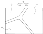
図1Aは、R-T-B系焼結磁石の一部を拡大して模式的に示す断面図であり、図1Bは図1Aの破線矩形領域内を更に拡大して模式的に示す断面図である。図1Aには、一例として長さ5μmの矢印が大きさを示す基準の長さとして参考のために記載されている。図1Aおよび図1Bに示されるように、R-T-B系焼結磁石は、主としてR2T14B化合物からなる主相12と、主相12の粒界部分に位置する粒界相14とから構成されている。また、粒界相14は、図1Bに示されるように、2つのR2T14B化合物粒子(グレイン)が隣接する二粒子粒界相14aと、3つのR2T14B化合物粒子が隣接する粒界三重点14bとを含む。典型的な主相結晶粒径は磁石断面の円相当径の平均値で3μm以上10μm以下である。主相12であるR2T14B化合物は高い飽和磁化と異方性磁界を持つ強磁性材料である。したがって、R-T-B系焼結磁石では、主相12であるR2T14B化合物の存在比率を高めることによってBrを向上させることができる。R2T14B化合物の存在比率を高めるためには、原料合金中のR量、T量、B量を、R2T14B化合物の化学量論比(R量:T量:B量=2:14:1)に近づければよい。なお、R2T14B化合物のBの一部はCで置換することが可能である。
また、主相であるR2T14B化合物のRの一部をDy、Tb、Hoなどの重希土類元素で置換することによって飽和磁化を下げつつ、主相の異方性磁界を高められることが知られている。特に二粒子粒界相と接する主相外殻は磁化反転の起点となりやすいため、主相外殻に優先的に重希土類元素を置換できる重希土類拡散技術は、飽和磁化の低下を抑制しつつ効率的に高いHcJが得られる。
一方、二粒子粒界相14aの磁性を制御することによっても、高いHcJが得られることが知られている。具体的には二粒子粒界相中の磁性元素(Fe、Co、Ni等)の濃度を下げることによって、二粒子粒界相を非磁性に近づけることで、主相同士の磁気的な結合を弱めて磁化反転を抑制することができる。
FIG. 1A is a cross-sectional view showing an enlarged portion of an R-T-B based sintered magnet, and FIG. 1B is a cross-sectional view showing an enlarged portion of the dashed rectangular region in FIG. 1A. In FIG. 1A, an arrow of 5 μm in length is shown as an example for reference as a reference length showing the size. As shown in FIG. 1A and FIG. 1B, the R-T-B based sintered magnet is composed of a
It is also known that the anisotropic magnetic field of the main phase can be increased while decreasing the saturation magnetization by substituting a part of R in the R 2 T 14 B compound, which is the main phase, with a heavy rare earth element such as Dy, Tb, or Ho. In particular, since the outer shell of the main phase in contact with the two-particle grain boundary phase is likely to be the starting point of magnetization reversal, the heavy rare earth diffusion technique, which can preferentially substitute heavy rare earth elements in the outer shell of the main phase, can efficiently obtain a high HcJ while suppressing the decrease in saturation magnetization.
On the other hand, it is known that a high HcJ can also be obtained by controlling the magnetism of the two-particle
本発明者は検討の結果、特許文献2に記載の方法は、重希土類元素の使用量を低減しつつ、高いHcJを有するR-T-B系焼結磁石が得られるものの、拡散によるBrの低下が起こる場合があることがわかった。このBrの低下は、拡散により磁石表面付近のR量(特にRL)が多くなることで、磁石表面付近における主相の体積比率が低下するためだと考えられる。こられの知見をもとに本発明者はさらに検討の結果、R-T-B系焼結磁石素材表面から粒界を通じて磁石素材内部へ、狭い特定範囲のCを特定範囲のRLおよびMとともに拡散させることで、磁石表面付近の主相の体積比率の低下を抑制することが可能になることを見出した。これにより拡散によるBrの低下を抑制させることができるため、重希土類元素の使用量を低減しつつ、BrとHcJのバランスに優れたR-T-B系焼結磁石を得ることができる。これは、磁石表面付近の粒界に存在するFeと拡散によって導入されたRLが、同じく拡散によって導入されたC(Bと置換可能なC)により主相を形成するからだと考えられる。 As a result of investigation, the present inventor found that the method described in Patent Document 2 can obtain an R-T-B based sintered magnet having a high HcJ while reducing the amount of heavy rare earth elements used, but that there are cases where B r decreases due to diffusion. It is believed that this decrease in B r is due to the fact that the amount of R (particularly RL) increases near the magnet surface due to diffusion, thereby decreasing the volume ratio of the main phase near the magnet surface. Based on these findings, the present inventor further investigated and found that it is possible to suppress the decrease in the volume ratio of the main phase near the magnet surface by diffusing a narrow specific range of C together with specific ranges of RL and M from the surface of the R-T-B based sintered magnet material through the grain boundaries into the magnet material. This makes it possible to suppress the decrease in B r due to diffusion, and therefore to obtain an R-T-B based sintered magnet with an excellent balance between B r and HcJ while reducing the amount of heavy rare earth elements used. It is believed that this is because Fe present in the grain boundaries near the magnet surface and RL introduced by diffusion form the main phase with C (C that can be substituted for B) also introduced by diffusion.
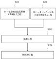
本開示によるR-T-B系焼結磁石の製造方法は、図2に示すように、R-T-B系焼結磁石素材を準備する工程S10とRL-RH-C-M系合金を準備する工程S20とを含む。R-T-B系焼結磁石素材を準備する工程S10とRL-RH-C-M系合金を準備する工程S20との順序は任意である。
本開示によるR-T-B系焼結磁石の製造方法は、図2に示すように、更に、R-T-B系焼結磁石素材表面の少なくとも一部にRL-RH-C-M系合金の少なくとも一部を付着させ、真空又は不活性ガス雰囲気中、700℃以上1100℃以下の温度で加熱する拡散工程S30を含む。
The method for producing a sintered R-T-B based magnet according to the present disclosure includes step S10 of preparing a sintered R-T-B based magnet material, and step S20 of preparing an RL-RH-C-M based alloy, as shown in Fig. 2. The order of step S10 of preparing the sintered R-T-B based magnet material and step S20 of preparing the RL-RH-C-M based alloy may be arbitrary.
As shown in FIG. 2, the method for producing a sintered R-T-B based magnet according to the present disclosure further includes a diffusion step S30 in which at least a part of an RL-RH-C-M based alloy is adhered to at least a part of the surface of the sintered R-T-B based magnet material, and then heated at a temperature of 700° C. or higher and 1100° C. or lower in a vacuum or inert gas atmosphere.
なお、本開示において、拡散工程前および拡散工程中のR-T-B系焼結磁石を「R-T-B系焼結磁石素材」と称し、拡散工程後のR-T-B系焼結磁石を単に「R-T-B系焼結磁石」と称する。 In this disclosure, the R-T-B based sintered magnet before and during the diffusion process is referred to as the "R-T-B based sintered magnet material," and the R-T-B based sintered magnet after the diffusion process is simply referred to as the "R-T-B based sintered magnet."
(R-T-B系焼結磁石素材を準備する工程)
R-T-B系焼結磁石素材において、Rは希土類元素であり、Nd、PrおよびCeからなる群から選択された少なくとも1つを必ず含み、TはFe、Co、Al、Mn、およびSiからなる群から選択された少なくとも1つであり、必ずFeを含む。Rの含有量は、例えば、R-T-B系焼結磁石素材全体の27mass%以上35mass%以下である。T全体に対するFeの含有量が80mass%以上であることが好ましい。
Rが27mass%未満では焼結過程で液相が十分に生成せず、焼結体を充分に緻密化することが困難になる可能性がある。一方、Rが35mass%を超えると焼結時に粒成長が起こり、HcJが低下する可能性がある。Rは28mass%以上33mass%以下であることが好ましい。
(Step of preparing R-T-B based sintered magnet material)
In the sintered R-T-B based magnet material, R is a rare earth element and necessarily contains at least one selected from the group consisting of Nd, Pr, and Ce, and T is at least one selected from the group consisting of Fe, Co, Al, Mn, and Si, and necessarily contains Fe. The content of R is, for example, 27 mass% or more and 35 mass% or less of the entire sintered R-T-B based magnet material. The content of Fe relative to the entire T is preferably 80 mass% or more.
If R is less than 27 mass%, the liquid phase is not sufficiently generated during the sintering process, and it may be difficult to sufficiently densify the sintered body. On the other hand, if R exceeds 35 mass%, grain growth occurs during sintering, and HcJ may decrease. R is preferably 28 mass% or more and 33 mass% or less.
R-T-B系焼結磁石素材は例えば、以下の組成範囲を有する。
R:27~35mass%、
B:0.80~1.20mass%、
Ga:0~1.0mass%、
X:0~2mass%(XはCu、Nb、Zrの少なくとも一種)、
T:60mass%以上を含有する。
The RTB based sintered magnet material has, for example, the following composition range.
R: 27-35 mass%,
B: 0.80 to 1.20 mass%,
Ga: 0 to 1.0 mass%,
X: 0 to 2 mass% (X is at least one of Cu, Nb, and Zr);
T: Contains 60 mass% or more.
好ましくは、R-T-B系焼結磁石素材において、Bに対するTのmol比[T]/[B]が14.0超15.0以下である。より高いHcJを得ることができる。本開示における[T]/[B]とは、Tを構成する各元素(Fe、Co、Al、MnおよびSiからなる群から選択された少なくとも1つであり、Tは必ずFeを含み、T全体に対するFeの含有量が80mass%以上)の分析値(mass%)をそれぞれの元素の原子量で除したものを求め、それらの値を合計したもの[T]と、Bの分析値(mass%)をBの原子量で除したもの[B]との比である。mol比[T]/[B]が14.0を超えるという条件は、主相(R2T14B化合物)形成に使われるT量に対して相対的にB量が少ないことを示している。mol比[T]/[B]は14.3以上15.0以下であることがさらに好ましい。さらに高いHcJを得ることができる。Bの含有量はR-T-B系焼結体全体の0.9mass%以上1.0mass%未満が好ましい。 Preferably, in the R-T-B based sintered magnet material, the molar ratio [T]/[B] of T to B is more than 14.0 and not more than 15.0. A higher H cJ can be obtained. In the present disclosure, [T]/[B] is the ratio of the analytical value (mass%) of each element constituting T (at least one selected from the group consisting of Fe, Co, Al, Mn, and Si, T necessarily contains Fe, and the content of Fe in the whole of T is 80 mass% or more) divided by the atomic weight of each element, the total value being [T], to the analytical value (mass%) of B divided by the atomic weight of B, [B]. The condition that the molar ratio [T]/[B] exceeds 14.0 indicates that the amount of B is relatively small compared to the amount of T used to form the main phase (R 2 T 14 B compound). It is more preferable that the molar ratio [T]/[B] is 14.3 or more and 15.0 or less. It is possible to obtain a higher HcJ . The content of B is preferably 0.9 mass % or more and less than 1.0 mass % of the entire RTB based sintered body.
R-T-B系焼結磁石素材は、Nd-Fe-B系焼結磁石に代表される一般的なR-T-B系焼結磁石の製造方法を用いて準備することができる。一例を挙げると、ストリップキャスト法等で作製された原料合金を、ジェットミルなどを用いて粒径D50が2.0μm以上5.0μm以下に粉砕した後、磁界中で成形し、900℃以上1100℃以下の温度で焼結することにより焼結体を作製して準備することができる。粒径D50が2.0μm以上5μm以下に粉砕することにより、高い磁気特性を得ることができる。好ましくは、粒径D50は、2.5μm以上4.0μm以下である。生産性の悪化を抑制した上で貴重なRHを削減しつつ、よりBrとHcJのバランスに優れたR-T-B系焼結磁石を得ることができる。なお、前記D50は、気流分散法によるレーザー回折法で得られる粒度分布において、小径側からの積算粒度分布(体積基準)が50%になる粒径である。また、D50は、例えば、Sympatec社製の粒度分布計測装置「HELOS&RODOS」を用いて、分散圧:4bar、測定レンジ:R2、計測モード:HRLDの条件にて測定することができる。 The R-T-B sintered magnet material can be prepared by using a general manufacturing method for R-T-B sintered magnets, such as Nd-Fe-B sintered magnets. For example, a raw alloy produced by strip casting or the like is crushed to a particle size D 50 of 2.0 μm to 5.0 μm using a jet mill or the like, then molded in a magnetic field, and sintered at a temperature of 900°C to 1100°C to produce a sintered body. High magnetic properties can be obtained by crushing to a particle size D 50 of 2.0 μm to 5 μm. Preferably, the particle size D 50 is 2.5 μm to 4.0 μm. It is possible to obtain an R-T-B sintered magnet with a better balance between B r and H cJ while reducing valuable RH while suppressing deterioration of productivity. The D 50 is the particle size at which the cumulative particle size distribution (volume basis) from the small diameter side becomes 50% in the particle size distribution obtained by the laser diffraction method using the airflow dispersion method. Furthermore, D50 can be measured, for example, using a particle size distribution measuring device "HELOS &RODOS" manufactured by Sympatec under the conditions of dispersion pressure: 4 bar, measurement range: R2, and measurement mode: HRLD.
(RL-RH-C-M系合金を準備する工程)
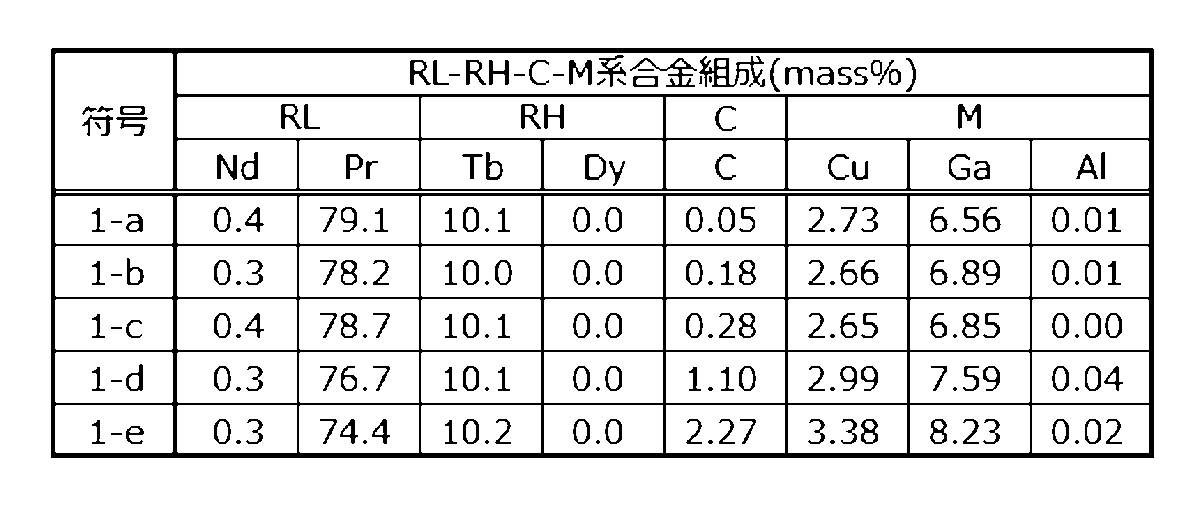
前記RL-RH-C-M系合金において、RLは軽希土類元素のうちの少なくとも1つであり、Nd、PrおよびCeからなる群から選択された少なくとも1つを必ず含み、RHは、Tb、DyおよびHoからなる群から選択された少なくとも1つであり、Cはカーボンであり、Mは、Cu、Ga、Fe、Co、Ni、Al、Ag、Zn、Si、Snからなる群から選択された少なくとも1つである。RLの含有量は、RL-RH-C-M系合金全体の50mass%以上95mass%以下である。軽希土類元素は、La、Ce、Pr、Nd、Pm、Sm、Euなどが挙げられる。RHの含有量は、RL-RH-C-M系合金全体の45mass%以下(0mass%を含む)である。すわなち、RHは含有しなくてもよい。Cの含有量は、RL-RH-C-M系合金全体の0.10mass%以上0.50mass%以下である。Mの含有量は、RL-RH-C-M系合金全体の4mass%以上49.9mass%以下である。RL-RH-C-M系合金の典型例は、TbNdPrCCu合金、TbNdCePCCu合金、TbNdPrCCuFe合金、TbNdCGa合金、TbNdPrCGaCu合金、TbNdCGaCuFe合金、NdPrTbCCuGaAl合金などである。上記元素の他にMn、O、N等の不可避不純物等の元素を少量含有してもよい。
(Step of preparing RL-RH-C-M alloy)
In the RL-RH-C-M alloy, RL is at least one of light rare earth elements, and necessarily includes at least one selected from the group consisting of Nd, Pr, and Ce, RH is at least one selected from the group consisting of Tb, Dy, and Ho, C is carbon, and M is at least one selected from the group consisting of Cu, Ga, Fe, Co, Ni, Al, Ag, Zn, Si, and Sn. The content of RL is 50 mass% or more and 95 mass% or less of the entire RL-RH-C-M alloy. Examples of light rare earth elements include La, Ce, Pr, Nd, Pm, Sm, and Eu. The content of RH is 45 mass% or less (including 0 mass%) of the entire RL-RH-C-M alloy. In other words, RH does not have to be contained. The C content is 0.10 mass% or more and 0.50 mass% or less of the entire RL-RH-C-M alloy. The M content is 4 mass% or more and 49.9 mass% or less of the entire RL-RH-C-M alloy. Typical examples of RL-RH-C-M alloys are TbNdPrCCu alloy, TbNdCePCCu alloy, TbNdPrCCuFe alloy, TbNdCGa alloy, TbNdPrCGaCu alloy, TbNdCGaCuFe alloy, NdPrTbCCuGaAl alloy, etc. In addition to the above elements, small amounts of elements such as inevitable impurities such as Mn, O, and N may be contained.
RL+RHが50mass%未満であると、RH、CおよびMがR-T-B系焼結磁石素材内部に導入されにくくなり、HcJが低下する可能性があり、95mass%を超えるとRL-RH-C-M系合金の製造工程中における合金粉末が非常に活性になる。その結果、合金粉末の著しい酸化や発火などを生じる可能性がある。好ましくは、RL+RHの含有量はRL-RH-C-M系合金全体の70mass%以上80mass%以下である。より高いHcJを得ることができる。 If RL+RH is less than 50 mass%, RH, C, and M are difficult to introduce into the R-T-B based sintered magnet material, and HcJ may decrease, whereas if it exceeds 95 mass%, the alloy powder during the manufacturing process of the RL-RH-C-M based alloy becomes very active. As a result, the alloy powder may be significantly oxidized or ignite. Preferably, the content of RL+RH is 70 mass% or more and 80 mass% or less of the entire RL-RH-C-M based alloy. A higher HcJ can be obtained.
RHが45mass%を超えると希少元素である重希土類元素の使用量を低減しつつ、BrとHcJのバランスに優れたR-T-B系焼結磁石を得ることができない。好ましくは、RHの含有量は、RL-RH-C-M系合金全体の20mass%以下である。また、RL-RH-C-M系合金における前記RLおよび前記RHの合計含有量は、RL-RH-C-M系合金全体の55mass%以上であることが好ましい。これにより、高いHcJを得ることができる。また、RL-RH-C-M系合金におけるRLの含有量(mass%)を[RL]、RHの含有量を[RH]とするとき、[RL]>1.5×[RH]の関係を満足することが好ましい。これにより、より重希土類元素の使用量を低減しつつ、BrとHcJのバランスに優れたR-T-B系焼結磁石を得ることができる。 If RH exceeds 45 mass%, it is not possible to obtain an R-T-B system sintered magnet with an excellent balance between B r and H cJ while reducing the amount of heavy rare earth elements used, which are rare elements. Preferably, the content of RH is 20 mass% or less of the entire RL-RH-C-M system alloy. Also, the total content of the RL and the RH in the RL-RH-C-M system alloy is preferably 55 mass% or more of the entire RL-RH-C-M system alloy. This allows a high H cJ to be obtained. Also, when the content (mass%) of RL in the RL-RH-C-M system alloy is [RL] and the content of RH is [RH], it is preferable to satisfy the relationship [RL]>1.5×[RH]. This allows a R-T-B system sintered magnet with an excellent balance between B r and H cJ to be obtained while reducing the amount of heavy rare earth elements used.
Cが0.10mass%未満であると、磁石表面付近の磁石表面付近の主相の体積比率の低下を抑制できない可能性があり、0.50mass%を超えると、RLおよびBによるHcJ向上効果が低下する可能性がある。好ましくは、Cの含有量は、RL-RH-C-M系合金全体の0.20mass%以上0.50mass%以下である。よりBrとHcJのバランスに優れたR-T-B系焼結磁石を得ることができる。 If the C content is less than 0.10 mass%, it may not be possible to suppress a decrease in the volume ratio of the main phase near the magnet surface, and if it exceeds 0.50 mass%, there is a possibility that the effect of improving HcJ due to RL and B may decrease. The C content is preferably 0.20 mass% or more and 0.50 mass% or less of the entire RL-RH-C-M based alloy. This makes it possible to obtain an R-T-B based sintered magnet with a better balance between B r and HcJ .
Mが4mass%未満であるとRL、BおよびRHが二粒子粒界相に導入されにくくなり、HcJが十分に向上しない可能性があり、49.9mass%を超えるとRLおよびBの含有量が低下しHcJが十分に向上しない可能性がある。好ましくは、Mの含有量は、RL-RH-C-M系合金全体の7mass%以上15mass%以下である。より高いHcJを得ることができる。好ましくは、前記RL-RH-C-M系合金のMは、Cu、Ga、Feの少なくとも1つを必ず含み、M中のCu、Ga、Feの含有割合は80%以上であると、より高いHcJを得ることができる。 If M is less than 4 mass%, RL, B and RH are difficult to introduce into the two-particle grain boundary phase, and H cJ may not be sufficiently improved, and if it exceeds 49.9 mass%, the contents of RL and B are decreased, and H cJ may not be sufficiently improved. Preferably, the content of M is 7 mass% or more and 15 mass% or less of the entire RL-RH-C-M alloy. A higher H cJ can be obtained. Preferably, M of the RL-RH-C-M alloy necessarily contains at least one of Cu, Ga and Fe, and the content ratio of Cu, Ga and Fe in M is 80% or more, and a higher H cJ can be obtained.
RL-RH-C-M系合金の作製方法は、特に限定されない。ロール急冷法によって作製してもよいし、鋳造法で作製してもよい。また、これらの合金を粉砕して合金粉末にしてもよい。遠心アトマイズ法、回転電極法、ガスアトマイズ法、プラズマアトマイズ法などの公知のアトマイズ法で作製してもよい。 The method for producing RL-RH-C-M alloys is not particularly limited. They may be produced by roll quenching or casting. These alloys may also be pulverized to produce alloy powder. They may also be produced by known atomization methods such as centrifugal atomization, rotating electrode method, gas atomization, and plasma atomization.
(拡散工程)
前述のように準備したR-T-B系焼結磁石素材の表面の少なくとも一部に、準備したRL-RH-C-M系合金の少なくとも一部を付着させ、真空又は不活性ガス雰囲気中、700℃以上1100℃以下の温度で加熱する拡散工程を行う。これにより、RL-RH-C-M系合金からRL、C、(RH)およびMを含む液相が生成し、その液相がR-T-B系焼結磁石素材中の粒界を経由して焼結素材表面から内部に拡散導入される。また、RL-RH-C-M系合金によるR-T-B系焼結磁石素材への付着量は1mass%以上8mass%以下が好ましく、1mass%以上5mass%以下がさらに好ましい。この範囲にすることにより、より確実に重希土類元素の使用量を低減しつつ、高いHcJを有するR-T-B系焼結磁石を得ることができる。
(Diffusion process)
At least a part of the prepared RL-RH-C-M alloy is attached to at least a part of the surface of the R-T-B system sintered magnet material prepared as described above, and a diffusion process is performed in which the alloy is heated in a vacuum or inert gas atmosphere at a temperature of 700°C to 1100°C. As a result, a liquid phase containing RL, C, (RH) and M is generated from the RL-RH-C-M alloy, and the liquid phase is diffused from the surface of the sintered material to the inside via the grain boundaries in the R-T-B system sintered magnet material. In addition, the amount of the RL-RH-C-M alloy attached to the R-T-B system sintered magnet material is preferably 1 mass% to 8 mass%, more preferably 1 mass% to 5 mass%. By setting the amount in this range, it is possible to more reliably reduce the amount of heavy rare earth elements used while obtaining an R-T-B system sintered magnet having a high HcJ .
拡散工程における加熱する温度が700℃未満であると、高いHcJを得ることができない可能性がある。一方、1100℃を超えるとHcJが大幅に低下する可能性がある。好ましくは、拡散工程における加熱する温度は800℃以上1000℃以下である。より高いHcJを得ることができる。また、好ましくは、拡散工程(700℃以上1100℃以下)が実施されたR-T-B系焼結磁石に対し、拡散工程を実施した温度から15℃/分以上の冷却速度で300℃まで冷却した方が好ましい。より高いHcJを得ることができる。 If the heating temperature in the diffusion step is less than 700°C, it may not be possible to obtain a high H cJ . On the other hand, if it exceeds 1100°C, there is a possibility that the H cJ will drop significantly. Preferably, the heating temperature in the diffusion step is 800°C or higher and 1000°C or lower. A higher H cJ can be obtained. Also, preferably, the R-T-B based sintered magnet that has been subjected to the diffusion step (700°C or higher and 1100°C or lower) is cooled from the temperature at which the diffusion step was performed to 300°C at a cooling rate of 15°C/min or higher. A higher H cJ can be obtained.
拡散工程は、R-T-B系焼結磁石素材表面に、任意形状のRL-RH-C-M系合金を配置し、公知の熱処理装置を用いて行うことができる。例えば、R-T-B系焼結磁石素材表面をRL-RH-C-M系合金の粉末層で覆い、拡散工程を行うことができる。例えば、塗布対象の表面に粘着剤を塗布する塗布工程と、粘着剤を塗布した領域にRL-RH-C-M系合金を付着させる工程を行ってもよい。粘着剤としては、PVA(ポリビニルアルコール)、PVB(ポリビニルブチラール)、PVP(ポリビニルピロリドン)などが挙げられる。粘着剤が水系の粘着剤の場合、塗布の前にR-T-B系焼結磁石素材を予備的に加熱してもよい。予備加熱の目的は余分な溶媒を除去し粘着力をコントロールすること、及び、均一に粘着剤を付着させることである。加熱温度は60~200℃が好ましい。揮発性の高い有機溶媒系の粘着剤の場合はこの工程は省略してもよい。また、例えばRL-RH-C-M系合金を分散媒中に分散させたスラリーをR-T-B系焼結磁石素材表面に塗布した後、分散媒を蒸発させRL-RH-C-M系合金とR-T-B系焼結磁石素材とを付着させてもよい。なお、分散媒として、アルコール(エタノール等)、アルデヒドおよびケトンを例示できる。
また、RL-RH-C-M系合金の少なくとも一部がR-T-B系焼結磁石素材の少なくとも一部に付着していれば、その配置位置は特に問わない。
The diffusion process can be carried out by disposing an RL-RH-C-M alloy of any shape on the surface of the R-T-B sintered magnet material and using a known heat treatment device. For example, the surface of the R-T-B sintered magnet material can be covered with a powder layer of the RL-RH-C-M alloy and then the diffusion process can be carried out. For example, a coating process of coating an adhesive on the surface to be coated and a process of attaching the RL-RH-C-M alloy to the area coated with the adhesive may be carried out. Examples of adhesives include PVA (polyvinyl alcohol), PVB (polyvinyl butyral), and PVP (polyvinyl pyrrolidone). When the adhesive is a water-based adhesive, the R-T-B sintered magnet material may be preheated before coating. The purpose of the preheating is to remove excess solvent to control the adhesive strength and to attach the adhesive uniformly. The heating temperature is preferably 60 to 200°C. In the case of a highly volatile organic solvent-based adhesive, this process may be omitted. Also, for example, a slurry in which the RL-RH-C-M alloy is dispersed in a dispersion medium may be applied to the surface of the sintered R-T-B based magnet material, and then the dispersion medium may be evaporated to allow the RL-RH-C-M alloy and the sintered R-T-B based magnet material to adhere to each other. Examples of the dispersion medium include alcohol (such as ethanol), aldehydes, and ketones.
Furthermore, so long as at least a portion of the RL-RH-CM based alloy is attached to at least a portion of the sintered RTB based magnet material, there is no particular limitation on the position where it is disposed.
(熱処理工程)
好ましくは、図2に示すように、拡散工程が実施されたR-T-B系焼結磁石に対して、真空又は不活性ガス雰囲気中、400℃以上900℃以下で、かつ、前記拡散工程で実施した温度よりも低い温度で熱処理を行う。熱処理は複数回行ってもよい。熱処理を行うことにより、より高いHcJを得ることができる。
(Heat treatment process)
2, the R-T-B based sintered magnet that has been subjected to the diffusion step is preferably subjected to a heat treatment in a vacuum or inert gas atmosphere at a temperature of 400° C. to 900° C., both inclusive, and at a temperature lower than the temperature used in the diffusion step. The heat treatment may be performed multiple times. By performing the heat treatment, a higher HcJ can be obtained.
(R-T-B系焼結磁石)
本開示の製造方法により得られたR-T-B系焼結磁石は、R(Rは希土類元素であり、Nd、PrおよびCeからなる群から選択された少なくとも1つを必ず含む。)、T(TはFe、Co、Al、Mn、およびSiからなる群から選択された少なくとも1つであり、必ずFeを含む)、BおよびCを含有し、さらに、Cu、Ga、Ni、Ag、Zn、Snからなる群から選択された少なくとも1つを含有する。
(RTB system sintered magnet)
The R-T-B based sintered magnet obtained by the manufacturing method of the present disclosure is composed of R (R is a rare earth element and necessarily contains at least one selected from the group consisting of Nd, Pr, and Ce), T (T is at least one selected from the group consisting of Fe, Co, Al, Mn, and Si, and always includes Fe), B, and C, and further contains Cu, Ga, Ni, Ag, It contains at least one selected from the group consisting of Zn and Sn.
本開示のR-T-B系焼結磁石は、例えば、下記の組成を有し得る。 The R-T-B based sintered magnet disclosed herein may have, for example, the following composition:
R:26.8mass%以上31.5mass%以下、
B:0.90mass%以上0.97mass%以下、
C:0.08mass%以上0.30mass%以下、
M:0.05mass%以上1.0mass%以下(Mは、Ga、Cu、ZnおよびSiからなる群から選択された少なくとも1種である)、
M1:0mass%以上2.0mass%以下(M1は、Al、Ti、V、Cr、Mn、Ni,Zr、Nb、Mo、Ag、In、Sn、Hf、Ta、W、Pb、およびBiからなる群から選択された少なくとも1種)
残部T(TはFe又はFeとCo)、および不可避的不純物からなる。
本開示は、重希土類元素の使用量を低減しつつ、BrとHcJのバランスに優れたR-T-B系焼結磁石を有することができる。そのため、特にTbは、R-T-B系焼結磁石全体の5mass%以下(0mass%を含む)が好ましく、さらに1mass%以下が好ましく、さらに0.5mass%以下が好ましい。
R: 26.8 mass% or more and 31.5 mass% or less,
B: 0.90 mass% or more and 0.97 mass% or less,
C: 0.08 mass% or more and 0.30 mass% or less,
M: 0.05 mass% or more and 1.0 mass% or less (M is at least one selected from the group consisting of Ga, Cu, Zn and Si);
M1: 0 mass% or more and 2.0 mass% or less (M1 is composed of Al, Ti, V, Cr, Mn, Ni, Zr, Nb, Mo, Ag, In, Sn, Hf, Ta, W, Pb, and Bi) At least one selected from the group
The balance consists of T (T is Fe or Fe and Co) and unavoidable impurities.
The present disclosure provides an R-T-B based sintered magnet that has an excellent balance between B r and H cJ while reducing the amount of heavy rare earth elements used. The content of this element is preferably 5 mass % or less (including 0 mass %) of the entire B-based sintered magnet, more preferably 1 mass % or less, and even more preferably 0.5 mass % or less.
また、本開示のR-T-B系焼結磁石は磁石表面から磁石内部に向かってRH(例えばTb)濃度が漸減する部分を含んでもよい。磁石表面から磁石内部に向かってRH濃度が漸減する部分をR-T-B系焼結磁石は含むということは、RHの少なくとも一方が磁石表面から磁石内部に拡散された状態にあることを意味している。 The R-T-B based sintered magnet of the present disclosure may also include a portion where the RH (e.g., Tb) concentration gradually decreases from the magnet surface toward the magnet interior. The fact that the R-T-B based sintered magnet includes a portion where the RH concentration gradually decreases from the magnet surface toward the magnet interior means that at least one of the RHs is in a state of being diffused from the magnet surface to the magnet interior.
本発明を実施例によりさらに詳細に説明するが、本発明はそれらに限定されるものではない。 The present invention will be described in more detail with reference to examples, but the present invention is not limited thereto.
実験例1
[R-T-B系焼結磁石素材(磁石素材)を準備する工程]
表1の符号1-Aに示す磁石素材の組成となるように、各元素を秤量しストリップキャスト法により鋳造し、厚み0.2~0.4mmのフレーク状の原料合金を得た。得られたフレーク状の原料合金を水素粉砕した後、550℃まで真空中で加熱後冷却する脱水素処理を施し粗粉砕粉を得た。次に、得られた粗粉砕粉を気流式粉砕機(ジェットミル装置)を用いて粉砕し、粒径D50が3μmの微粉砕粉(合金粉末)を得た。なお、粒径D50は、気流分散法によるレーザー回折法で得られた体積中心値(体積基準メジアン径)である。
Experimental Example 1
[Step of preparing R-T-B based sintered magnet material (magnetic material)]
Each element was weighed and cast by strip casting so as to obtain the composition of the magnet material shown in Table 1-A, and a flake-shaped raw alloy having a thickness of 0.2 to 0.4 mm was obtained. The obtained flake-shaped raw alloy was subjected to hydrogen pulverization, and then to a dehydrogenation treatment in which the alloy was heated to 550°C in a vacuum and then cooled, to obtain a coarsely pulverized powder. The obtained coarsely pulverized powder was then pulverized using an airflow pulverizer (jet mill device) to obtain a finely pulverized powder (alloy powder) having a particle size D50 of 3 μm. The particle size D50 is the volume center value (volume-based median diameter) obtained by a laser diffraction method using an airflow dispersion method.
前記微粉砕粉を磁界中で成形し成形体を得た。なお、成形装置には、磁界印加方向と加圧方向とが直交するいわゆる直角磁界成形装置(横磁界成形装置)を用いた。 The finely pulverized powder was molded in a magnetic field to obtain a green body. The molding device used was a so-called perpendicular magnetic field molding device (horizontal magnetic field molding device) in which the magnetic field application direction and the pressure direction are perpendicular to each other.
得られた成形体を、真空中で4時間焼結(サンプル毎に焼結による緻密化が十分起こる温度を選定)した後急冷し、磁石素材を得た。得られた磁石素材の密度は7.5Mg/m3 以上であった。得られた磁石素材の成分の結果を表1に示す。なお、表1における各成分は、高周波誘導結合プラズマ発光分光分析法(ICP-OES)を使用して測定した。なお、磁石素材の酸素量をガス融解-赤外線吸収法で測定した結果、すべて0.2mass%前後であることを確認した。また、C(炭素量)は、燃焼-赤外線吸収法によるガス分析装置を使用して測定した結果、0.1mass%前後であることを確認した。表1における「[T]/[B]」は、Tを構成する各元素(ここではFe、Al、Si、Mn)に対し、分析値(mass%)をその元素の原子量で除したものを求め、それらの値を合計したもの(a)と、Bの分析値(mass%)をBの原子量で除したもの(b)との比(a/b)である。以下の全ての表も同様である。なお、表1の各組成および酸素量、炭素量を合計しても100mass%にはならない。これは、表に記載された元素以外の不純物元素を含むためである。その他表についても同様である。 The obtained compact was sintered in a vacuum for 4 hours (a temperature at which densification by sintering was sufficiently achieved was selected for each sample) and then quenched to obtain a magnetic material. The density of the obtained magnetic material was 7.5 Mg/ m3 or more. The results of the composition of the obtained magnetic material are shown in Table 1. Note that each component in Table 1 was measured using inductively coupled plasma optical emission spectroscopy (ICP-OES). Note that the oxygen content of the magnetic material was measured by gas fusion-infrared absorption method, and it was confirmed that all were around 0.2 mass%. Furthermore, C (carbon content) was measured using a gas analyzer by combustion-infrared absorption method, and it was confirmed that it was around 0.1 mass%. In Table 1, "[T]/[B]" is the ratio (a/b) of the sum (a) of the analytical value (mass%) of each element (here, Fe, Al, Si, Mn) constituting T divided by the atomic weight of the element, and the sum (b) of the analytical value (mass%) of B divided by the atomic weight of B. The same applies to all the following tables. The sum of each composition, oxygen amount, and carbon amount in Table 1 does not equal 100 mass%. This is because impurity elements other than those listed in the table are included. The same applies to the other tables.

[RL-RH-C-M系合金を準備する工程]
表2の符号1-a~1-eに示すRL-RH-C-M系合金の組成となるように、各元素を秤量しそれらの原料を溶解して、単ロール超急冷法(メルトスピニング法)によりリボンまたはフレーク状の合金を得た。得られた合金を乳鉢を用いてアルゴン雰囲気中で粉砕しRL-RH-C-M系合金を準備した。得られたRL-RH-C-M系合金の組成を表2に示す。
[Step of preparing RL-RH-C-M alloy]
Each element was weighed out and the raw materials were melted to obtain the RL-RH-C-M alloy composition shown by symbols 1-a to 1-e in Table 2, and a ribbon or flake-shaped alloy was obtained by a single-roll ultra-quenching method (melt spinning method). The obtained alloy was pulverized in an argon atmosphere using a mortar to prepare a RL-RH-C-M alloy. The composition of the obtained RL-RH-C-M alloy is shown in Table 2.
[拡散工程]
表1の符号1-AのR-T-B系焼結磁石素材を切断、切削加工し、7.2mm×7.2mm×7.2mmの立方体とした。次に、R-T-B系焼結磁石素材にディッピング法により糖アルコール類を含有する粘着剤をR-T-B系焼結磁石素材の全面に塗布した。粘着剤を塗布したR-T-B系焼結磁石素材にRL-RH-C-M系合金粉末をR-T-B系焼結磁石素材の質量に対し3mass%付着させた。次に、真空熱処理炉を用いて900℃で10時間の条件で前記RL-RH-C-M系合金及び前記R-T-B系焼結磁石素材を加熱して拡散工程を実施した後、冷却した。その後、真空熱処理炉を用いて470℃以上530℃以下で3時間の条件で熱処理を実施した後、冷却した。
[Diffusion process]
The R-T-B based sintered magnet material with the reference number 1-A in Table 1 was cut and machined to a cube of 7.2 mm x 7.2 mm x 7.2 mm. Next, an adhesive containing sugar alcohols was applied to the entire surface of the R-T-B based sintered magnet material by a dipping method. RL-RH-C-M based alloy powder was attached to the R-T-B based sintered magnet material coated with the adhesive in an amount of 3 mass% based on the mass of the R-T-B based sintered magnet material. Next, the RL-RH-C-M based alloy and the R-T-B based sintered magnet material were heated in a vacuum heat treatment furnace at 900°C for 10 hours to carry out a diffusion process, and then cooled. Then, a heat treatment was carried out in a vacuum heat treatment furnace at 470°C to 530°C for 3 hours, and then cooled.
[サンプル評価]
R-T-B系焼結磁石素材および得られたサンプル(熱処理後のR-T-B系焼結磁石)を、B-Hトレーサによって各試料のBr及びHcJを測定した。R-T-B系焼結磁石のBrおよびHcJの測定結果、及び、R-T-B系焼結磁石のBr値(拡散後のBr)からR-T-B系焼結磁石素材のBr値(拡散前のBr)を差し引いた値を△Brとして表3に示す。また、サンプルの成分を高周波誘導結合プラズマ発光分光分析法(ICP-OES)を使用して測定した結果を表4に示す。表3の通りR-T-B系焼結磁石素材であるサンプルNo.1-1を用いてRL-RH-C-M系合金を拡散させたサンプルNo.1-3~1-4の実施例は、いずれも拡散工程で高いHcJが得られているだけでなく、Brの低下が少ないことが分かる。よって、BrとHcJのバランスに優れた(Brの低下を抑制しつつ、高いHcJの)R-T-B系焼結磁石が得られている。一方、C量が適正範囲以下のRL-RH-C-M系合金を拡散させたサンプルNo.1-2の比較例は拡散工程で高いHcJが得られているもののBrが大きく低下していることが分かる。また、C量が適正範囲以上のRL-RH-C-M系合金を拡散させたサンプルNo.1-5および1-6の比較例はBrの低下は少ないが、十分なHcJが得られていないことが分かる。
[Sample evaluation]
The B r and H cJ of the R-T-B based sintered magnet material and the obtained sample (R-T-B based sintered magnet after heat treatment) were measured using a B-H tracer. The measurement results of B r and H cJ of the R-T-B based sintered magnet, and the value obtained by subtracting the B r value of the R-T-B based sintered magnet material (B r before diffusion) from the B r value of the R-T-B based sintered magnet (B r after diffusion) are shown in Table 3 as △B r . In addition, the results of measuring the components of the samples using inductively coupled plasma optical emission spectroscopy (ICP-OES) are shown in Table 4. As shown in Table 3, it can be seen that the examples of Sample No. 1-3 to 1-4, in which an RL-RH-C-M based alloy was diffused using Sample No. 1-1, which is an R-T-B based sintered magnet material, all not only obtained high H cJ in the diffusion process, but also showed little decrease in B r . Thus, an R-T-B based sintered magnet with an excellent balance between B r and H cJ (high H cJ while suppressing the decrease in B r ) was obtained. On the other hand, it can be seen that the comparative example of sample No. 1-2, in which an RL-RH-C-M based alloy with a C amount below the appropriate range was diffused, achieved a high H cJ in the diffusion process, but B r was significantly decreased. Also, it can be seen that the comparative examples of sample Nos. 1-5 and 1-6, in which an RL-RH-C-M based alloy with a C amount above the appropriate range was diffused, achieved only a small decrease in B r , but did not achieve a sufficient H cJ .


実験例2
[R-T-B系焼結磁石素材(磁石素材)を準備する工程]
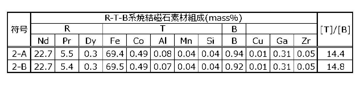
表5の符号2-A~2-Bに示す磁石素材の組成となるように、各元素を秤量しストリップキャスト法により鋳造し、厚み0.2~0.4mmのフレーク状の原料合金を得た。得られたフレーク状の原料合金を水素粉砕した後、550℃まで真空中で加熱後冷却する脱水素処理を施し粗粉砕粉を得た。次に、得られた粗粉砕粉を気流式粉砕機(ジェットミル装置)を用いて粉砕し、粒径D50が3μmの微粉砕粉(合金粉末)を得た。なお、粒径D50は、気流分散法によるレーザー回折法で得られた体積中心値(体積基準メジアン径)である。
Experimental Example 2
[Step of preparing R-T-B based sintered magnet material (magnetic material)]
Each element was weighed and cast by strip casting so as to obtain the composition of the magnet material shown in Table 5, which is indicated by symbols 2-A to 2-B, to obtain a flake-shaped raw alloy having a thickness of 0.2 to 0.4 mm. The obtained flake-shaped raw alloy was subjected to hydrogen pulverization, and then to a dehydrogenation treatment in which the alloy was heated to 550°C in a vacuum and then cooled to obtain a coarsely pulverized powder. The obtained coarsely pulverized powder was then pulverized using an airflow pulverizer (jet mill device) to obtain a finely pulverized powder (alloy powder) having a particle size D50 of 3 μm. The particle size D50 is the volume center value (volume-based median diameter) obtained by a laser diffraction method using an airflow dispersion method.
前記微粉砕粉を磁界中で成形し成形体を得た。なお、成形装置には、磁界印加方向と加圧方向とが直交するいわゆる直角磁界成形装置(横磁界成形装置)を用いた。 The finely pulverized powder was molded in a magnetic field to obtain a green body. The molding device used was a so-called perpendicular magnetic field molding device (horizontal magnetic field molding device) in which the magnetic field application direction and the pressure direction are perpendicular to each other.
得られた成形体を、真空中、1000℃以上1050℃以下(サンプル毎に焼結による緻密化が十分起こる温度を選定)で10時間焼結した後急冷し、磁石素材を得た。得られた磁石素材の密度は7.5Mg/m3 以上であった。得られた磁石素材の成分の結果を表5に示す。なお、表5における各成分は、高周波誘導結合プラズマ発光分光分析法(ICP-OES)を使用して測定した。なお、磁石素材の酸素量をガス融解-赤外線吸収法で測定した結果、すべて0.2mass%前後であることを確認した。また、C(炭素量)は、燃焼-赤外線吸収法によるガス分析装置を使用して測定した結果、0.1mass%前後であることを確認した。 The obtained compact was sintered in a vacuum at 1000°C to 1050°C (a temperature at which densification by sintering occurs sufficiently for each sample) for 10 hours, and then quenched to obtain a magnetic material. The density of the obtained magnetic material was 7.5 Mg/m3 or more. The results of the composition of the obtained magnetic material are shown in Table 5. Note that each component in Table 5 was measured using high-frequency inductively coupled plasma optical emission spectroscopy (ICP-OES). Note that the oxygen content of the magnetic material was measured by gas fusion-infrared absorption method, and it was confirmed that all were around 0.2 mass%. Also, C (carbon content) was measured using a gas analyzer by combustion-infrared absorption method, and it was confirmed that it was around 0.1 mass%.
[RL-RH-C-M系合金を準備する工程]
表6の符号2-a~2-eに示すRL-RH-C-M系合金の組成およびBを含まない合金の組成となるように、各元素を秤量しそれらの原料を溶解して、単ロール超急冷法(メルトスピニング法)によりリボンまたはフレーク状の合金を得た。得られた合金を乳鉢を用いてアルゴン雰囲気中で粉砕しRL-RH-C-M系合金を準備した。得られたRL-RH-C-M系合金の組成を表6に示す。
[Step of preparing RL-RH-C-M alloy]
Each element was weighed so as to obtain the composition of the RL-RH-C-M alloy and the composition of the alloy not containing B shown in Table 6, and the raw materials were melted and obtained as ribbon or flake-shaped alloys by a single roll ultra-quenching method (melt spinning method). The obtained alloys were pulverized in an argon atmosphere using a mortar to prepare RL-RH-C-M alloys. The compositions of the obtained RL-RH-C-M alloys are shown in Table 6.

[拡散工程]
表5の符号2-A~2-BのR-T-B系焼結磁石素材を切断、切削加工し、7.2mm×7.2mm×7.2mmの立方体とした。次に、R-T-B系焼結磁石素材にディッピング法により糖アルコール類を含有する粘着剤をR-T-B系焼結磁石素材の全面に塗布した。粘着剤を塗布したR-T-B系焼結磁石素材にRL-RH-C-M系合金粉末をR-T-B系焼結磁石素材の質量に対し3mass%付着させた。次に、真空熱処理炉を用いて900℃で10時間の条件で前記RL-RH-C-M系合金及び前記R-T-B系焼結磁石素材を加熱して拡散工程を実施した後、冷却した。その後、真空熱処理炉を用いて470℃以上530℃以下で1時間の条件で熱処理を実施した後、冷却した。
[Diffusion process]
The R-T-B sintered magnet materials of symbols 2-A to 2-B in Table 5 were cut and machined to obtain cubes of 7.2 mm x 7.2 mm x 7.2 mm. Next, an adhesive containing sugar alcohols was applied to the entire surface of the R-T-B sintered magnet material by dipping. RL-RH-C-M alloy powder was attached to the R-T-B sintered magnet material coated with the adhesive in an amount of 3 mass% based on the mass of the R-T-B sintered magnet material. Next, the RL-RH-C-M alloy and the R-T-B sintered magnet material were heated in a vacuum heat treatment furnace at 900°C for 10 hours to carry out a diffusion process, and then cooled. Then, a heat treatment was carried out in a vacuum heat treatment furnace at 470°C to 530°C for 1 hour, and then cooled.
[サンプル評価]
R-T-B系焼結磁石素材および得られたサンプル(熱処理後のR-T-B系焼結磁石)を、B-Hトレーサによって各試料のBr及びHcJを測定した。R-T-B系焼結磁石のBrおよびHcJの測定結果、及び、R-T-B系焼結磁石のBr値(拡散後のBr)からR-T-B系焼結磁石素材のBr値(拡散前のBr)を差し引いた値を△Brとして表7に示す。表7の通りR-T-B系焼結磁石素材であるサンプルNo.2-1、サンプルNo.2-7を用いてRL-RH-C-M系合金を拡散させたサンプルNo.2-3~2-5、サンプルNo.2-9~2-10の実施例は、いずれも拡散工程で高いHcJが得られているだけでなく、Brの低下が少ないことが分かる。よって、BrとHcJのバランスに優れたR-T-B系焼結磁石が得られている。一方、C量が適正範囲以下のRL-RH-C-M系合金を拡散させたサンプルNo.2-2、No.2-8の比較例は拡散工程で高いHcJが得られているもののBrが大きく低下しており、また、サンプルNo.2-6、サンプルNo.2-11の比較例は、Brの低下は少ないが、十分なHcJが得られていないことが分かる。
[Sample evaluation]
The B r and H cJ of the R-T-B based sintered magnet material and the obtained sample (R-T-B based sintered magnet after heat treatment) were measured using a B-H tracer. The measurement results of B r and H cJ of the R-T-B based sintered magnets, as well as the value obtained by subtracting the B r value of the R-T-B based sintered magnet material (B r before diffusion) from the B r value of the R-T-B based sintered magnet (B r after diffusion) are shown in Table 7 as △B r . As shown in Table 7, it can be seen that the examples of Sample No. 2-3 to 2-5 and Sample No. 2-9 to 2-10 in which an RL-RH-C-M based alloy was diffused using Sample No. 2-1 and Sample No. 2-7, which are R-T-B based sintered magnet materials, all not only achieved high H cJ in the diffusion process, but also showed little decrease in B r . Thus, an R-T-B based sintered magnet with an excellent balance between B r and H cJ was obtained. On the other hand, in the comparative examples of Sample No. 2-2 and No. 2-8 in which an RL-RH-C-M based alloy with a C amount below the appropriate range was diffused, high H cJ was obtained in the diffusion process, but B r was significantly reduced, and in the comparative examples of Sample No. 2-6 and Sample No. 2-11, the reduction in B r was small, but sufficient H cJ was not obtained.

12 R2T14B化合物からなる主相
14 粒界相
14a 二粒子粒界相
14b 粒界三重点
12 R 2 T 14 Main phase consisting of
Claims (2)
前記R-T-B系焼結磁石素材の表面の少なくとも一部に、RL-RH-C-M系合金(RLは軽希土類元素のうちの少なくとも1つであり、Nd、PrおよびCeからなる群から選択された少なくとも1つを必ず含み、RHは、Tb、DyおよびHoからなる群から選択された少なくとも1つであり、Cはカーボンであり、Mは、Cu、Ga、Fe、Co、Ni、Al、Ag、Zn、Si、Snからなる群から選択された少なくとも1つである。)の少なくとも一部を付着させ、真空又は不活性ガス雰囲気中、700℃以上1100℃以下の温度で加熱する拡散工程と、を含み、
前記R-T-B系焼結磁石素材は、Bに対するTのmol比[T]/[B]が14.0超15.0以下であり、
前記RL-RH-C-M系合金における、RLの含有量は50mass%以上95mass%以下であり、RHの含有量は45mass%以下(0mass%を含む)であり、Cの含有量は0.10mass%以上0.50mass%以下であり、Mの含有量は4mass%以上49.9mass%以下である、R-T-B系焼結磁石の製造方法。 preparing an R-T-B based sintered magnet material (R is a rare earth element and must include at least one selected from the group consisting of Nd, Pr, and Ce, and T is at least one selected from the group consisting of Fe, Co, Al, Mn, and Si, and must include Fe);
a diffusion step of depositing at least a portion of an RL-RH-C-M alloy (RL is at least one light rare earth element and necessarily includes at least one selected from the group consisting of Nd, Pr, and Ce, RH is at least one selected from the group consisting of Tb, Dy, and Ho, C is carbon, and M is at least one selected from the group consisting of Cu, Ga, Fe, Co, Ni, Al, Ag, Zn, Si, and Sn) on at least a portion of the surface of the R-T-B based sintered magnet material, and heating the resulting material at a temperature of 700° C. or higher and 1100° C. or lower in a vacuum or in an inert gas atmosphere;
The R-T-B based sintered magnet material has a molar ratio of T to B, [T]/[B], of more than 14.0 and not more than 15.0;
The RL-RH-C-M alloy has an RL content of 50 mass% or more and 95 mass% or less, an RH content of 45 mass% or less (including 0 mass%), a C content of 0.10 mass% or more and 0.50 mass% or less, and an M content of 4 mass% or more and 49.9 mass% or less.
Priority Applications (2)
| Application Number | Priority Date | Filing Date | Title |
|---|---|---|---|
| JP2021049197A JP7582002B2 (en) | 2021-03-23 | 2021-03-23 | Manufacturing method of RTB based sintered magnet |
| CN202210157081.0A CN115116726A (en) | 2021-03-23 | 2022-02-21 | Method for producing R-T-B sintered magnet |
Applications Claiming Priority (1)
| Application Number | Priority Date | Filing Date | Title |
|---|---|---|---|
| JP2021049197A JP7582002B2 (en) | 2021-03-23 | 2021-03-23 | Manufacturing method of RTB based sintered magnet |
Publications (2)
| Publication Number | Publication Date |
|---|---|
| JP2022147793A JP2022147793A (en) | 2022-10-06 |
| JP7582002B2 true JP7582002B2 (en) | 2024-11-13 |
Family
ID=83325023
Family Applications (1)
| Application Number | Title | Priority Date | Filing Date |
|---|---|---|---|
| JP2021049197A Active JP7582002B2 (en) | 2021-03-23 | 2021-03-23 | Manufacturing method of RTB based sintered magnet |
Country Status (2)
| Country | Link |
|---|---|
| JP (1) | JP7582002B2 (en) |
| CN (1) | CN115116726A (en) |
Families Citing this family (1)
| Publication number | Priority date | Publication date | Assignee | Title |
|---|---|---|---|---|
| JP7794099B2 (en) * | 2022-10-19 | 2026-01-06 | トヨタ自動車株式会社 | R-T-B rare earth magnet and its manufacturing method |
Citations (5)
| Publication number | Priority date | Publication date | Assignee | Title |
|---|---|---|---|---|
| JP2007194599A (en) | 2005-12-22 | 2007-08-02 | Hitachi Ltd | Low loss magnet and magnetic circuit using it |
| JP2012248827A (en) | 2011-05-02 | 2012-12-13 | Shin Etsu Chem Co Ltd | Rare earth permanent magnet and method for producing the same |
| WO2015020181A1 (en) | 2013-08-09 | 2015-02-12 | Tdk株式会社 | R-t-b-based sintered magnet and motor |
| JP2015057820A (en) | 2013-08-09 | 2015-03-26 | Tdk株式会社 | R-T-B sintered magnet |
| WO2016093174A1 (en) | 2014-12-12 | 2016-06-16 | 日立金属株式会社 | Production method for r-t-b-based sintered magnet |
-
2021
- 2021-03-23 JP JP2021049197A patent/JP7582002B2/en active Active
-
2022
- 2022-02-21 CN CN202210157081.0A patent/CN115116726A/en active Pending
Patent Citations (5)
| Publication number | Priority date | Publication date | Assignee | Title |
|---|---|---|---|---|
| JP2007194599A (en) | 2005-12-22 | 2007-08-02 | Hitachi Ltd | Low loss magnet and magnetic circuit using it |
| JP2012248827A (en) | 2011-05-02 | 2012-12-13 | Shin Etsu Chem Co Ltd | Rare earth permanent magnet and method for producing the same |
| WO2015020181A1 (en) | 2013-08-09 | 2015-02-12 | Tdk株式会社 | R-t-b-based sintered magnet and motor |
| JP2015057820A (en) | 2013-08-09 | 2015-03-26 | Tdk株式会社 | R-T-B sintered magnet |
| WO2016093174A1 (en) | 2014-12-12 | 2016-06-16 | 日立金属株式会社 | Production method for r-t-b-based sintered magnet |
Also Published As
| Publication number | Publication date |
|---|---|
| JP2022147793A (en) | 2022-10-06 |
| CN115116726A (en) | 2022-09-27 |
Similar Documents
| Publication | Publication Date | Title |
|---|---|---|
| JP7588618B2 (en) | RTB series permanent magnet | |
| CN101944430B (en) | Rare earth magnet and its preparation | |
| JP6414654B1 (en) | Method for producing RTB-based sintered magnet | |
| JP6614084B2 (en) | Method for producing R-Fe-B sintered magnet | |
| JP6414653B1 (en) | Method for producing RTB-based sintered magnet | |
| WO2016133071A1 (en) | Method for producing r-t-b system sintered magnet | |
| JP6451900B2 (en) | R-Fe-B sintered magnet and method for producing the same | |
| JP4677942B2 (en) | Method for producing R-Fe-B rare earth sintered magnet | |
| JP6939337B2 (en) | Manufacturing method of RTB-based sintered magnet | |
| JP6508447B1 (en) | Method of manufacturing RTB based sintered magnet | |
| JP7582002B2 (en) | Manufacturing method of RTB based sintered magnet | |
| CN111489874A (en) | Method for producing R-T-B sintered magnet | |
| JP7533424B2 (en) | Manufacturing method of rare earth sintered magnet | |
| JP7447606B2 (en) | RTB system sintered magnet | |
| JP7661811B2 (en) | Manufacturing method of RTB based sintered magnet and RTB based sintered magnet | |
| JP2020120102A (en) | Method for manufacturing r-t-b based sintered magnet | |
| JP7452159B2 (en) | Manufacturing method of RTB based sintered magnet | |
| CN115116725A (en) | Manufacturing method of R-T-B based sintered magnet and R-T-B based sintered magnet | |
| JP6610957B2 (en) | Method for producing RTB-based sintered magnet | |
| JP7310499B2 (en) | Method for producing RTB based sintered magnet | |
| JP7631955B2 (en) | Manufacturing method of RTB based sintered magnet | |
| JP6939338B2 (en) | Manufacturing method of RTB-based sintered magnet | |
| CN111489888B (en) | Method for producing R-T-B sintered magnet | |
| JP7567558B2 (en) | Manufacturing method of RTB based sintered magnet | |
| JP7476601B2 (en) | Manufacturing method of RTB based sintered magnet |
Legal Events
| Date | Code | Title | Description |
|---|---|---|---|
| A621 | Written request for application examination |
Free format text: JAPANESE INTERMEDIATE CODE: A621 Effective date: 20240115 |
|
| A977 | Report on retrieval |
Free format text: JAPANESE INTERMEDIATE CODE: A971007 Effective date: 20240829 |
|
| TRDD | Decision of grant or rejection written | ||
| A01 | Written decision to grant a patent or to grant a registration (utility model) |
Free format text: JAPANESE INTERMEDIATE CODE: A01 Effective date: 20241001 |
|
| A61 | First payment of annual fees (during grant procedure) |
Free format text: JAPANESE INTERMEDIATE CODE: A61 Effective date: 20241014 |
|
| R150 | Certificate of patent or registration of utility model |
Ref document number: 7582002 Country of ref document: JP Free format text: JAPANESE INTERMEDIATE CODE: R150 |