JP7565093B2 - ステッピングモータの駆動装置 - Google Patents
ステッピングモータの駆動装置 Download PDFInfo
- Publication number
- JP7565093B2 JP7565093B2 JP2022160687A JP2022160687A JP7565093B2 JP 7565093 B2 JP7565093 B2 JP 7565093B2 JP 2022160687 A JP2022160687 A JP 2022160687A JP 2022160687 A JP2022160687 A JP 2022160687A JP 7565093 B2 JP7565093 B2 JP 7565093B2
- Authority
- JP
- Japan
- Prior art keywords
- stepping motor
- current
- excitation
- rotation speed
- excitation current
- Prior art date
- Legal status (The legal status is an assumption and is not a legal conclusion. Google has not performed a legal analysis and makes no representation as to the accuracy of the status listed.)
- Active
Links
- 230000005284 excitation Effects 0.000 claims description 147
- 238000004804 winding Methods 0.000 claims description 36
- 238000001514 detection method Methods 0.000 claims description 20
- 230000008859 change Effects 0.000 claims description 15
- 238000000034 method Methods 0.000 claims description 2
- 230000008569 process Effects 0.000 claims description 2
- 238000010586 diagram Methods 0.000 description 12
- 238000005259 measurement Methods 0.000 description 8
- 238000004519 manufacturing process Methods 0.000 description 7
- 239000004065 semiconductor Substances 0.000 description 7
- KNMAVSAGTYIFJF-UHFFFAOYSA-N 1-[2-[(2-hydroxy-3-phenoxypropyl)amino]ethylamino]-3-phenoxypropan-2-ol;dihydrochloride Chemical compound Cl.Cl.C=1C=CC=CC=1OCC(O)CNCCNCC(O)COC1=CC=CC=C1 KNMAVSAGTYIFJF-UHFFFAOYSA-N 0.000 description 6
- 230000007423 decrease Effects 0.000 description 6
- 230000007246 mechanism Effects 0.000 description 6
- 230000020169 heat generation Effects 0.000 description 5
- 230000000052 comparative effect Effects 0.000 description 4
- 230000006870 function Effects 0.000 description 4
- RYGMFSIKBFXOCR-UHFFFAOYSA-N Copper Chemical compound [Cu] RYGMFSIKBFXOCR-UHFFFAOYSA-N 0.000 description 2
- XEEYBQQBJWHFJM-UHFFFAOYSA-N Iron Chemical compound [Fe] XEEYBQQBJWHFJM-UHFFFAOYSA-N 0.000 description 2
- 230000008602 contraction Effects 0.000 description 2
- 229910052802 copper Inorganic materials 0.000 description 2
- 239000010949 copper Substances 0.000 description 2
- 238000002474 experimental method Methods 0.000 description 2
- 230000003287 optical effect Effects 0.000 description 2
- 238000007493 shaping process Methods 0.000 description 2
- 230000001133 acceleration Effects 0.000 description 1
- 230000005540 biological transmission Effects 0.000 description 1
- 238000004891 communication Methods 0.000 description 1
- 230000003247 decreasing effect Effects 0.000 description 1
- 230000000694 effects Effects 0.000 description 1
- 230000007613 environmental effect Effects 0.000 description 1
- 239000011810 insulating material Substances 0.000 description 1
- 230000010354 integration Effects 0.000 description 1
- 229910052742 iron Inorganic materials 0.000 description 1
- 230000002093 peripheral effect Effects 0.000 description 1
- 238000012545 processing Methods 0.000 description 1
- 230000009467 reduction Effects 0.000 description 1
- 230000004044 response Effects 0.000 description 1
- 229920006395 saturated elastomer Polymers 0.000 description 1
Images


Landscapes
- Control Of Stepping Motors (AREA)
Description
かかる分析装置は、ステッピングモータの回転軸をボールネジ等からなるネジ機構部を介して試料テーブルに連結し、ステッピングモータを回転駆動させることにより試料テーブルをX方向、Y方向及びZ方向などに移動させると共に、所望の停止位置を保持するよう構成されている。
また、従来、ステッピングモータの駆動装置は、ステッピングモータの回転数にかかわらず、ステッピングモータに通電する励磁電流の電流値を一定に設定して当該ステッピングモータを回転駆動するよう構成されている。
しかしながら、ステッピングモータの励磁電流の値を一定に設定して当該ステッピングモータを回転駆動すると、図12に示されるように、ステッピングモータの回転数に応じて出力トルクが変動する(特許文献2)。
このように、従来のステッピングモータの駆動装置では、ステッピングモータの回転数に応じて発生トルクが変動するが、当然のことながら、ステッピングモータの励磁電流の値は、当該ステッピングモータに要求される出力トルクを上回るよう設定される。そのため、ステッピングモータに要求される出力トルクを上回る励磁電流が無駄に費消され、ステッピングモータの不本位な温度上昇等を招くという技術的課題を有している。
前記励磁シーケンスを規格化された値として生成する励磁シーケンス生成手段と、
前記励磁シーケンス生成手段が生成する規格化された前記励磁シーケンスが一方に入力され、他方に入力される信号であって前記励磁電流の電流設定値を決定する信号と乗算処理を行う乗算部と、
前記乗算部から出力される乗算処理後の前記励磁シーケンスに応じて前記ステッピングモータの各巻線に通電する励磁電流を制御する手段であって、出力端子毎に2つの電流制御素子を有する出力部と、前記2つの電流制御素子を駆動する駆動回路と、前記出力部から前記ステッピングモータの各巻線に流れる前記励磁電流を検出する電流検出部と、前記電流検出部の検出信号に基づいて前記ステッピングモータの各巻線に通電される前記励磁電流の電流値が前記乗算部から出力される乗算処理後の前記励磁シーケンスと等しくなるよう前記駆動回路を制御する電流制御回路とを有する電流制御出力手段と、
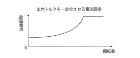
負荷の駆動に必要な必要トルクが一定の条件下で前記ステッピングモータを一定の励磁電流で駆動したとき、予め定められた回転数以下では出力トルクが前記必要トルクを上回るのを抑制して前記出力トルクを一定に維持するように、前記励磁電流の電流設定値を決定する信号を前記ステッピングモータの回転数に応じて変更する変更手段と、
を備えるステッピングモータの駆動装置である。
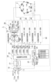
図1は、本参考実施の形態1に係るステッピングモータの駆動装置を示すブロック図である。
本参考実施の形態1に係るステッピングモータの駆動装置1は、次のようにして、停止時を含めステッピングモータ2の回転数が変化した場合であっても、ステッピングモータ2の発熱量が変動するのを抑制することが可能となっている。
図9は本発明の参考実施の形態1に係るステッピングモータの駆動装置1において励磁電流値を図8のように変化させた場合にステッピングモータ2の発熱量の変化に伴って当該ステッピングモータ2の温度がどのように変化するかを確認する実験例1及び比較例1の結果を示すグラフである。
Δt=ΔQ/C
と表すことができる。
図11は、実施の形態1に係るステッピングモータの駆動装置を示すブロック図である。
図17は本発明の本実施の形態1に係るステッピングモータの駆動装置1において励磁電流値を図16に示すように変化させた場合にステッピングモータ2の出力トルクがどのように変化するかを確認した実験例2の結果を示すグラフである。
T=(スプリング秤の読み)×(プーリの半径)
によって与えられる。
2…ステッピングモータ
11…入力回路
21…アップダウンカウンタ
22…励磁電流生成部
30…電流制御及び出力部
23…入力周波数計測カウンタ
24…テーブル参照部
25…乗算部
Claims (6)
- 指令情報に基づいてステッピングモータを駆動する励磁シーケンスを生成し、前記励磁シーケンスに基づいて前記ステッピングモータの複数の巻線に励磁電流として通電して駆動するステッピングモータの駆動装置において、
前記励磁シーケンスを規格化された値として生成する励磁シーケンス生成手段と、
前記励磁シーケンス生成手段が生成する規格化された前記励磁シーケンスが一方に入力され、他方に入力される信号であって前記励磁電流の電流設定値を決定する信号と乗算処理を行う乗算部と、
前記乗算部から出力される乗算処理後の前記励磁シーケンスに応じて前記ステッピングモータの各巻線に通電する励磁電流を制御する手段であって、出力端子毎に2つの電流制御素子を有する出力部と、前記2つの電流制御素子を駆動する駆動回路と、前記出力部から前記ステッピングモータの各巻線に流れる前記励磁電流を検出する電流検出部と、前記電流検出部の検出信号に基づいて前記ステッピングモータの各巻線に通電される前記励磁電流の電流値が前記乗算部から出力される乗算処理後の前記励磁シーケンスと等しくなるよう前記駆動回路を制御する電流制御回路とを有する電流制御出力手段と、
負荷の駆動に必要な必要トルクが一定の条件下で前記ステッピングモータを一定の励磁電流で駆動したとき、予め定められた回転数以下では出力トルクが前記必要トルクを上回るのを抑制して前記出力トルクを一定に維持するように、前記励磁電流の電流設定値を決定する信号を前記ステッピングモータの回転数に応じて変更する変更手段と、
を備えるステッピングモータの駆動装置。 - 前記変更手段は、前記励磁電流の電流設定値を一定として前記ステッピングモータの回転数を変化させた場合における前記ステッピングモータのトルク変動に基づいて前記ステッピングモータの回転数に対する前記励磁電流の電流設定値が決定される請求項1に記載のステッピングモータの駆動装置。
- 前記変更手段は、前記ステッピングモータの駆動時における前記励磁電流の電流設定値を停止時と同じ値か停止時よりも大きな値に変更する請求項2に記載のステッピングモータの駆動装置。
- 前記変更手段は、前記ステッピングモータの回転数に対する前記励磁電流の電流設定値の関係を予め記憶したテーブルを有する請求項1に記載のステッピングモータの駆動装置。
- 前記指令情報に基づいて前記ステッピングモータの指令回転数を検出する検出手段を備える請求項1に記載のステッピングモータの駆動装置。
- 前記変更手段は、前記検出手段の検出結果に基づいて前記励磁電流の電流設定値を変更する請求項5に記載のステッピングモータの駆動装置。
Priority Applications (1)
| Application Number | Priority Date | Filing Date | Title |
|---|---|---|---|
| JP2022160687A JP7565093B2 (ja) | 2020-09-11 | 2022-10-05 | ステッピングモータの駆動装置 |
Applications Claiming Priority (2)
| Application Number | Priority Date | Filing Date | Title |
|---|---|---|---|
| JP2020152888A JP7160373B2 (ja) | 2020-09-11 | 2020-09-11 | ステッピングモータの駆動装置 |
| JP2022160687A JP7565093B2 (ja) | 2020-09-11 | 2022-10-05 | ステッピングモータの駆動装置 |
Related Parent Applications (1)
| Application Number | Title | Priority Date | Filing Date |
|---|---|---|---|
| JP2020152888A Division JP7160373B2 (ja) | 2020-09-11 | 2020-09-11 | ステッピングモータの駆動装置 |
Publications (2)
| Publication Number | Publication Date |
|---|---|
| JP2022185079A JP2022185079A (ja) | 2022-12-13 |
| JP7565093B2 true JP7565093B2 (ja) | 2024-10-10 |
Family
ID=80780179
Family Applications (2)
| Application Number | Title | Priority Date | Filing Date |
|---|---|---|---|
| JP2020152888A Active JP7160373B2 (ja) | 2020-09-11 | 2020-09-11 | ステッピングモータの駆動装置 |
| JP2022160687A Active JP7565093B2 (ja) | 2020-09-11 | 2022-10-05 | ステッピングモータの駆動装置 |
Family Applications Before (1)
| Application Number | Title | Priority Date | Filing Date |
|---|---|---|---|
| JP2020152888A Active JP7160373B2 (ja) | 2020-09-11 | 2020-09-11 | ステッピングモータの駆動装置 |
Country Status (1)
| Country | Link |
|---|---|
| JP (2) | JP7160373B2 (ja) |
Citations (1)
| Publication number | Priority date | Publication date | Assignee | Title |
|---|---|---|---|---|
| WO2006132115A1 (ja) | 2005-06-08 | 2006-12-14 | Rohm Co., Ltd. | 撮像装置 |
Family Cites Families (2)
| Publication number | Priority date | Publication date | Assignee | Title |
|---|---|---|---|---|
| JP3135746B2 (ja) * | 1993-05-18 | 2001-02-19 | 日本パルスモーター株式会社 | パルスモータ定電流駆動回路及び5相パルスモータのバイポーラペンタゴン定電流駆動回路 |
| JP4494593B2 (ja) * | 2000-06-14 | 2010-06-30 | 株式会社エム・システム技研 | 保温機能付きステッピングモータ |
-
2020
- 2020-09-11 JP JP2020152888A patent/JP7160373B2/ja active Active
-
2022
- 2022-10-05 JP JP2022160687A patent/JP7565093B2/ja active Active
Patent Citations (1)
| Publication number | Priority date | Publication date | Assignee | Title |
|---|---|---|---|---|
| WO2006132115A1 (ja) | 2005-06-08 | 2006-12-14 | Rohm Co., Ltd. | 撮像装置 |
Also Published As
| Publication number | Publication date |
|---|---|
| JP2022047142A (ja) | 2022-03-24 |
| JP7160373B2 (ja) | 2022-10-25 |
| JP2022185079A (ja) | 2022-12-13 |
Similar Documents
| Publication | Publication Date | Title |
|---|---|---|
| US6078158A (en) | Disk drive motor spin-up control | |
| JPH0514513B2 (ja) | ||
| US20080037164A1 (en) | Adaptive spindle motor startup method and disk drive using the same | |
| CN1326319C (zh) | 步进电机驱动装置 | |
| JP2008178288A (ja) | モータの位置決め装置 | |
| JPH0426391A (ja) | ブラシレスモータ制御装置 | |
| JP7565093B2 (ja) | ステッピングモータの駆動装置 | |
| JP6613216B2 (ja) | モータ制御回路、モータ制御装置、アクチュエータ及びステッピングモータの制御方法 | |
| JP3700106B2 (ja) | センサレス・スイッチドリラクタンスモータの駆動回路 | |
| KR20040017175A (ko) | 스텝모터의 제어장치 및 제어방법 | |
| KR20220160654A (ko) | 스테핑 모터 제어 장치 | |
| JPH0313834B2 (ja) | ||
| JP3239535B2 (ja) | ブラシレスモータの停止方法 | |
| JP2003224998A (ja) | ステッピングモータ駆動方法 | |
| CN115411986A (zh) | 马达驱动控制装置、马达单元以及马达驱动控制方法 | |
| JP2013031294A (ja) | モータ制御装置 | |
| JP4745838B2 (ja) | 電動アクチュエータの制御方法及び装置 | |
| JPH035156B2 (ja) | ||
| JPH0731183A (ja) | ブラシレスモータの駆動制御装置 | |
| US10469010B2 (en) | Motor drive controller, control method for motor drive controller, control program for motor drive controller, and method for determining number of divisions of basic step angle | |
| JP4005775B2 (ja) | 同期モータの磁極認識方法 | |
| Constandinou | Stepper motors uncovered (1) | |
| JP2008131799A (ja) | ステッピングモータ駆動回路とその制御方法 | |
| JP2020089094A (ja) | モータ駆動装置およびその制御方法、撮像装置 | |
| WO2025041838A1 (ja) | モータ制御装置およびモータ制御方法 |
Legal Events
| Date | Code | Title | Description |
|---|---|---|---|
| A621 | Written request for application examination |
Free format text: JAPANESE INTERMEDIATE CODE: A621 Effective date: 20221005 |
|
| A977 | Report on retrieval |
Free format text: JAPANESE INTERMEDIATE CODE: A971007 Effective date: 20231023 |
|
| A131 | Notification of reasons for refusal |
Free format text: JAPANESE INTERMEDIATE CODE: A131 Effective date: 20231107 |
|
| A521 | Request for written amendment filed |
Free format text: JAPANESE INTERMEDIATE CODE: A523 Effective date: 20231228 |
|
| A131 | Notification of reasons for refusal |
Free format text: JAPANESE INTERMEDIATE CODE: A131 Effective date: 20240206 |
|
| A521 | Request for written amendment filed |
Free format text: JAPANESE INTERMEDIATE CODE: A523 Effective date: 20240405 |
|
| A131 | Notification of reasons for refusal |
Free format text: JAPANESE INTERMEDIATE CODE: A131 Effective date: 20240618 |
|
| A521 | Request for written amendment filed |
Free format text: JAPANESE INTERMEDIATE CODE: A523 Effective date: 20240819 |
|
| TRDD | Decision of grant or rejection written | ||
| A01 | Written decision to grant a patent or to grant a registration (utility model) |
Free format text: JAPANESE INTERMEDIATE CODE: A01 Effective date: 20240917 |
|
| A61 | First payment of annual fees (during grant procedure) |
Free format text: JAPANESE INTERMEDIATE CODE: A61 Effective date: 20240920 |
|
| R150 | Certificate of patent or registration of utility model |
Ref document number: 7565093 Country of ref document: JP Free format text: JAPANESE INTERMEDIATE CODE: R150 |