JP7536552B2 - ポンプ装置 - Google Patents
ポンプ装置 Download PDFInfo
- Publication number
- JP7536552B2 JP7536552B2 JP2020139862A JP2020139862A JP7536552B2 JP 7536552 B2 JP7536552 B2 JP 7536552B2 JP 2020139862 A JP2020139862 A JP 2020139862A JP 2020139862 A JP2020139862 A JP 2020139862A JP 7536552 B2 JP7536552 B2 JP 7536552B2
- Authority
- JP
- Japan
- Prior art keywords
- circulation
- motor
- casing
- liquid
- impeller
- Prior art date
- Legal status (The legal status is an assumption and is not a legal conclusion. Google has not performed a legal analysis and makes no representation as to the accuracy of the status listed.)
- Active
Links
- 238000005086 pumping Methods 0.000 title 1
- 239000007788 liquid Substances 0.000 claims description 74
- 238000012806 monitoring device Methods 0.000 claims description 13
- 238000001514 detection method Methods 0.000 description 14
- 238000010586 diagram Methods 0.000 description 10
- 238000000034 method Methods 0.000 description 5
- 238000009434 installation Methods 0.000 description 3
- 230000015572 biosynthetic process Effects 0.000 description 1
- 238000001816 cooling Methods 0.000 description 1
- 230000000694 effects Effects 0.000 description 1
- 230000005484 gravity Effects 0.000 description 1
- 239000000463 material Substances 0.000 description 1
- 238000012986 modification Methods 0.000 description 1
- 230000004048 modification Effects 0.000 description 1
- 230000002093 peripheral effect Effects 0.000 description 1
- 238000007789 sealing Methods 0.000 description 1
- 239000007787 solid Substances 0.000 description 1
Images


Landscapes
- Structures Of Non-Positive Displacement Pumps (AREA)
- Connection Of Motors, Electrical Generators, Mechanical Devices, And The Like (AREA)
Description
一態様では、前記循環羽根は、前記モータを挟んで前記羽根車とは反対側の反負荷側に配置されている。
一態様では、前記循環羽根は、前記羽根車に隣接する負荷側に配置されており、前記ポンプ装置は、前記回転軸に固定され、かつ前記羽根車に作用する軸方向推力を打ち消すバランスディスクを備えている。
一態様では、前記バランスディスクは、前記バランスディスクに衝突する液体の力が作用する方向に傾斜するテーパー形状を有している。
一態様では、前記バランスディスクの直径は、前記循環羽根の直径よりも大きい。
一態様では、前記循環羽根は、カスケード羽根である。
一態様では、前記羽根車は、複数の羽根車である。
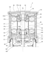
8 吸込口
9 吐出口
20 羽根車
22 回転軸
24 ポンプケーシング
25 ケーシングカバー
26 流通孔
30 モータ
31,32 すべり軸受
33,34 スラスト板
35 モータケーシング
36 モータロータ
37 モータステータ
37a ステータコア
37b コイル
38 エンドカバー
39 モータフレーム
40,41 キャン
46 流通孔
56 流通孔
100 循環羽根
101 循環カバー
101a カバー部
101b フレーム部
102 ケーシング部
105 軸受
105a 回転側軸受体
105b 固定側軸受体
110 シール部材
111 シール部材
120 バランスディスク
121 空気抜き孔
130 距離センサ
130a,130b 検出素子
135 摩耗監視装置
135a 記憶装置
135b 演算装置
150 溝部
151 吸込孔
152 吐出孔
160 ライナーリング
Claims (12)
- 液体を移送するための羽根車と、
前記羽根車を固定する回転軸と、
前記羽根車を収容するポンプケーシングと、
前記回転軸に固定されたモータロータおよび前記モータロータの周囲に配置されたモータステータから構成された、前記回転軸を回転するモータと、
前記モータを収容するモータケーシングと、
前記モータケーシングに形成された、液体を通過させる流通孔と、
前記回転軸に固定され、かつ液体を前記流通孔に導く循環羽根と、
前記循環羽根の回転によって昇圧された液体が流れる循環流路を前記モータケーシングとの間に形成する循環カバーと、を備えており、
前記モータケーシングは、
前記ポンプケーシングに固定されたケーシングカバーと、
前記モータを挟んで、前記ケーシングカバーの反対側に配置されたエンドカバーと、を備えており、
前記流通孔は、前記ケーシングカバーおよび前記エンドカバーのそれぞれに形成されており、
前記循環カバーは、
前記エンドカバーに隣接して配置されたカバー部と、
前記カバー部に接続され、前記モータケーシングのモータフレームを取り囲むフレーム部と、を備えており、
前記循環流路は、前記モータロータと前記モータステータとの間の第1空間と、前記フレーム部と前記モータフレームとの間の第2空間と、の間で循環する液体の流路であり、
前記循環羽根は、前記第1空間と、前記エンドカバーの中央に形成された前記流通孔と、を通じて、前記モータケーシングの外部に流出した液体を前記カバー部に衝突させて、放射状に流出する液体を前記第2空間に流入させる、ポンプ装置。 - 前記循環羽根は、前記モータを挟んで前記羽根車とは反対側の反負荷側に配置されている、請求項1に記載のポンプ装置。
- 前記循環羽根は、前記羽根車に隣接する負荷側に配置されており、
前記ポンプ装置は、前記回転軸に固定され、かつ前記羽根車に作用する軸方向推力を打ち消すバランスディスクを備えている、請求項1に記載のポンプ装置。 - 前記バランスディスクは、前記バランスディスクに衝突する液体に含まれる空気を通過させる空気抜き孔を有している、請求項3に記載のポンプ装置。
- 前記バランスディスクは、前記バランスディスクに衝突する液体の力が作用する方向に傾斜するテーパー形状を有している、請求項3または請求項4に記載のポンプ装置。
- 前記バランスディスクの直径は、前記循環羽根の直径よりも大きい、請求項3~請求項5のいずれか一項に記載のポンプ装置。
- 前記ポンプ装置は、
前記バランスディスクの軸線方向への移動距離を検出する距離センサと、
前記距離センサに接続された摩耗監視装置と、を備えており、
前記摩耗監視装置は、前記距離センサによって検出された前記バランスディスクの移動距離に基づいて、前記回転軸を支持する軸受の摩耗を監視する、請求項3~請求項6のいずれか一項に記載のポンプ装置。 - 前記循環羽根は、カスケード羽根である、請求項1~請求項7のいずれか一項に記載のポンプ装置。
- 前記カスケード羽根は、それ自身に軸方向推力を発生させずに、前記循環流路を形成する、請求項8に記載のポンプ装置。
- 前記羽根車は、複数の羽根車である、請求項1~請求項9のいずれか一項に記載のポンプ装置。
- 前記循環カバーは、前記循環流路を通過する液体を再び、前記循環羽根によって前記流通孔に導く、請求項1~請求項10のいずれか一項に記載のポンプ装置。
- 前記ケーシングカバーは、前記循環羽根を収容するケーシング部を有しており、
前記ケーシング部は、
前記循環羽根の回転によって、前記液体を前記ケーシング部の内部に流入させる吸込孔と、
前記循環羽根の回転によって昇圧された前記液体を、前記回転軸を支持する軸受に導くための吐出孔と、を有している、請求項1~請求項11のいずれか一項に記載のポンプ装置。
Priority Applications (1)
| Application Number | Priority Date | Filing Date | Title |
|---|---|---|---|
| JP2020139862A JP7536552B2 (ja) | 2020-08-21 | 2020-08-21 | ポンプ装置 |
Applications Claiming Priority (1)
| Application Number | Priority Date | Filing Date | Title |
|---|---|---|---|
| JP2020139862A JP7536552B2 (ja) | 2020-08-21 | 2020-08-21 | ポンプ装置 |
Publications (2)
| Publication Number | Publication Date |
|---|---|
| JP2022035496A JP2022035496A (ja) | 2022-03-04 |
| JP7536552B2 true JP7536552B2 (ja) | 2024-08-20 |
Family
ID=80443448
Family Applications (1)
| Application Number | Title | Priority Date | Filing Date |
|---|---|---|---|
| JP2020139862A Active JP7536552B2 (ja) | 2020-08-21 | 2020-08-21 | ポンプ装置 |
Country Status (1)
| Country | Link |
|---|---|
| JP (1) | JP7536552B2 (ja) |
Citations (4)
| Publication number | Priority date | Publication date | Assignee | Title |
|---|---|---|---|---|
| JP2000154795A (ja) | 1998-11-19 | 2000-06-06 | Mitsubishi Heavy Ind Ltd | 遠心ポンプのバランスディスク装置 |
| JP2001323889A (ja) | 2000-03-06 | 2001-11-22 | Ebara Corp | 全周流型モータポンプ |
| CN106194769A (zh) | 2016-08-31 | 2016-12-07 | 池泉 | 一种静音离心泵 |
| JP2017180781A (ja) | 2016-03-31 | 2017-10-05 | 株式会社荏原製作所 | 軸組立体、モータ軸、モータ、モータポンプ、および軸組立体の製造方法 |
Family Cites Families (5)
| Publication number | Priority date | Publication date | Assignee | Title |
|---|---|---|---|---|
| JPS5943695U (ja) * | 1982-09-17 | 1984-03-22 | 株式会社荏原製作所 | 水中モ−タポンプ |
| JPH0743221U (ja) * | 1990-12-20 | 1995-08-18 | 株式会社帝国電機製作所 | グランドレスポンプ |
| JPH087142Y2 (ja) * | 1991-02-15 | 1996-03-04 | 日機装株式会社 | 軸受摩耗監視装置 |
| JPH06249182A (ja) * | 1993-02-22 | 1994-09-06 | Hitachi Ltd | キャンドモータ形ポンプ |
| JPH0828484A (ja) * | 1994-07-15 | 1996-01-30 | Kubota Corp | ポンプ |
-
2020
- 2020-08-21 JP JP2020139862A patent/JP7536552B2/ja active Active
Patent Citations (4)
| Publication number | Priority date | Publication date | Assignee | Title |
|---|---|---|---|---|
| JP2000154795A (ja) | 1998-11-19 | 2000-06-06 | Mitsubishi Heavy Ind Ltd | 遠心ポンプのバランスディスク装置 |
| JP2001323889A (ja) | 2000-03-06 | 2001-11-22 | Ebara Corp | 全周流型モータポンプ |
| JP2017180781A (ja) | 2016-03-31 | 2017-10-05 | 株式会社荏原製作所 | 軸組立体、モータ軸、モータ、モータポンプ、および軸組立体の製造方法 |
| CN106194769A (zh) | 2016-08-31 | 2016-12-07 | 池泉 | 一种静音离心泵 |
Also Published As
| Publication number | Publication date |
|---|---|
| JP2022035496A (ja) | 2022-03-04 |
Similar Documents
| Publication | Publication Date | Title |
|---|---|---|
| US6129507A (en) | Method and device for reducing axial thrust in rotary machines and a centrifugal pump using same | |
| US6254361B1 (en) | Shaftless canned rotor inline pipe pump | |
| JP2012007592A (ja) | シール装置及びこれを備えた流体機械 | |
| JP2006508315A (ja) | 玉軸受およびこの形式の軸受が装備された真空ポンプ | |
| JP6747354B2 (ja) | 遠心圧縮機 | |
| EP3922859B1 (en) | Centrifugal compressor | |
| KR102281117B1 (ko) | 터보 압축기 | |
| WO2012001997A1 (ja) | シール装置及びこれを備えた流体機械 | |
| JP7536552B2 (ja) | ポンプ装置 | |
| JP2017032118A (ja) | 軸封装置および回転機械 | |
| JPH02196191A (ja) | 電動ポンプ装置 | |
| US10240609B2 (en) | Screw pump and impeller fan assemblies and method of operating | |
| JP2015175240A (ja) | 軸受装置及びこれを備えた立軸ポンプ | |
| JP6126850B2 (ja) | 軸封装置及びポンプ装置 | |
| JP6325969B2 (ja) | オイルリタン機構を有する水中電動ポンプ | |
| CN119755126B (zh) | 一种多级离心泵轴向力平衡机构及多级离心泵 | |
| US10669850B2 (en) | Impeller-type liquid ring compressor | |
| JP6591601B2 (ja) | オイルリタン機構を有する水中電動ポンプ | |
| KR102333286B1 (ko) | 유체 베어링이 적용된 극저온 냉매 펌프 | |
| CN216950876U (zh) | 一种稀土永磁驱动单级单吸离心泵 | |
| CN114526240B (zh) | 一种稀土永磁驱动单级单吸离心泵、冲洗及自润滑方法 | |
| JPH02173393A (ja) | 軸流ポンプの軸推力軽減装置 | |
| KR100558054B1 (ko) | 일체형원자로 smart 주냉각재펌프 | |
| JP6746277B2 (ja) | ポンプ | |
| JP2017009043A (ja) | 軸受装置およびポンプ |
Legal Events
| Date | Code | Title | Description |
|---|---|---|---|
| A621 | Written request for application examination |
Free format text: JAPANESE INTERMEDIATE CODE: A621 Effective date: 20230314 |
|
| A977 | Report on retrieval |
Free format text: JAPANESE INTERMEDIATE CODE: A971007 Effective date: 20230927 |
|
| A131 | Notification of reasons for refusal |
Free format text: JAPANESE INTERMEDIATE CODE: A131 Effective date: 20231003 |
|
| A601 | Written request for extension of time |
Free format text: JAPANESE INTERMEDIATE CODE: A601 Effective date: 20231204 |
|
| A521 | Request for written amendment filed |
Free format text: JAPANESE INTERMEDIATE CODE: A523 Effective date: 20231211 |
|
| A131 | Notification of reasons for refusal |
Free format text: JAPANESE INTERMEDIATE CODE: A131 Effective date: 20240305 |
|
| A601 | Written request for extension of time |
Free format text: JAPANESE INTERMEDIATE CODE: A601 Effective date: 20240501 |
|
| A521 | Request for written amendment filed |
Free format text: JAPANESE INTERMEDIATE CODE: A523 Effective date: 20240520 |
|
| TRDD | Decision of grant or rejection written | ||
| A01 | Written decision to grant a patent or to grant a registration (utility model) |
Free format text: JAPANESE INTERMEDIATE CODE: A01 Effective date: 20240806 |
|
| A61 | First payment of annual fees (during grant procedure) |
Free format text: JAPANESE INTERMEDIATE CODE: A61 Effective date: 20240807 |
|
| R150 | Certificate of patent or registration of utility model |
Ref document number: 7536552 Country of ref document: JP Free format text: JAPANESE INTERMEDIATE CODE: R150 |