JP7536552B2 - Pumping equipment - Google Patents
Pumping equipment Download PDFInfo
- Publication number
- JP7536552B2 JP7536552B2 JP2020139862A JP2020139862A JP7536552B2 JP 7536552 B2 JP7536552 B2 JP 7536552B2 JP 2020139862 A JP2020139862 A JP 2020139862A JP 2020139862 A JP2020139862 A JP 2020139862A JP 7536552 B2 JP7536552 B2 JP 7536552B2
- Authority
- JP
- Japan
- Prior art keywords
- circulation
- motor
- casing
- liquid
- impeller
- Prior art date
- Legal status (The legal status is an assumption and is not a legal conclusion. Google has not performed a legal analysis and makes no representation as to the accuracy of the status listed.)
- Active
Links
- 238000005086 pumping Methods 0.000 title 1
- 239000007788 liquid Substances 0.000 claims description 74
- 238000012806 monitoring device Methods 0.000 claims description 13
- 238000001514 detection method Methods 0.000 description 14
- 238000010586 diagram Methods 0.000 description 10
- 238000000034 method Methods 0.000 description 5
- 238000009434 installation Methods 0.000 description 3
- 230000015572 biosynthetic process Effects 0.000 description 1
- 238000001816 cooling Methods 0.000 description 1
- 230000000694 effects Effects 0.000 description 1
- 230000005484 gravity Effects 0.000 description 1
- 239000000463 material Substances 0.000 description 1
- 238000012986 modification Methods 0.000 description 1
- 230000004048 modification Effects 0.000 description 1
- 230000002093 peripheral effect Effects 0.000 description 1
- 238000007789 sealing Methods 0.000 description 1
- 239000007787 solid Substances 0.000 description 1
Images


Landscapes
- Structures Of Non-Positive Displacement Pumps (AREA)
- Connection Of Motors, Electrical Generators, Mechanical Devices, And The Like (AREA)
Description
本発明は、ポンプ装置に関する。 The present invention relates to a pump device.
近年、取扱液の多様化(高価な液、反応性/腐食性液)、設置場所(室内、装置内)の制約等が存在する条件下で使用可能なポンプが要求されている。しかしながら、通常のメカニカルシールでは、液体の漏洩を完全に防止することができないため、このような液体の漏洩への対策が求められている。 In recent years, there has been a demand for pumps that can be used under conditions such as a diversification of handled liquids (expensive liquids, reactive/corrosive liquids) and restrictions on installation locations (indoors, inside equipment). However, normal mechanical seals cannot completely prevent liquid leakage, so measures against leakage of such liquids are required.
また、多段ポンプにおいては、さらなる高圧化の要求が進む中、通常のメカニカルシールとは異なる高価な部材で構成したものを使用することでの対応が求められている。さらに、省エネ化によるポンプの小型化による高速化に伴うメカニカルシールの負荷も増加傾向にあり、メカニカルシールでの軸封対応にも限界が見えつつある。このような状況の中、メカニカルシールを必要としないキャンドモータを使用したポンプが求められている。 In addition, as the demand for higher pressures continues to grow for multi-stage pumps, there is a demand to use seals made of more expensive materials than normal mechanical seals. Furthermore, the load on mechanical seals is also increasing as pumps become smaller and faster in an effort to save energy, and the limits of mechanical seals for shaft sealing are becoming apparent. In these circumstances, there is a demand for pumps that use canned motors that do not require mechanical seals.
キャンドモータポンプでは、その内部に取扱液を循環させるために、主に外部配管流路による外部循環方式と、内部循環流路による内部循環方式と、が採用される。外部循環方式では、外部に別途配管を施工する必要があり、組立性と設置スペースの課題がある。内部循環方式では、主軸に貫通孔(軸通孔)を形成する必要がある。しかしながら、このような貫通孔を形成することは技術的に難易度が高く、特に、多段ポンプにおいては、主軸の長さが長いため、貫通孔を形成することは、より一層困難である。 Canned motor pumps mainly use two methods to circulate the handled liquid inside them: an external circulation method using an external piping flow path, and an internal circulation method using an internal circulation flow path. The external circulation method requires the installation of separate piping on the outside, which poses issues in terms of assembly and installation space. The internal circulation method requires the formation of a through hole (shaft through hole) in the main shaft. However, forming such a through hole is technically difficult, and in particular, in multi-stage pumps, the main shaft is long, making it even more difficult to form a through hole.
そこで、本発明は、簡単な構造で取扱液を循環させることができるポンプ装置を提供することを目的とする。 Therefore, the present invention aims to provide a pump device that can circulate the handled liquid with a simple structure.
一態様では、液体を移送するための羽根車と、前記羽根車を固定する回転軸と、前記羽根車を収容するポンプケーシングと、前記回転軸に固定されたモータロータおよび前記モータロータの周囲に配置されたモータステータから構成された、前記回転軸を回転するモータと、前記モータを収容するモータケーシングと、前記モータケーシングに形成された、液体を通過させる流通孔と、前記回転軸に固定され、かつ液体を前記流通孔に導く循環羽根と、前記循環羽根の回転によって昇圧された液体が流れる循環流路を前記モータケーシングとの間に形成する循環カバーと、を備えている、ポンプ装置が提供される。 In one aspect, a pump device is provided that includes an impeller for transporting liquid, a rotating shaft to which the impeller is fixed, a pump casing that houses the impeller, a motor that rotates the rotating shaft and is composed of a motor rotor fixed to the rotating shaft and a motor stator arranged around the motor rotor, a motor casing that houses the motor, a circulation hole formed in the motor casing to allow liquid to pass through, a circulation impeller fixed to the rotating shaft and guiding the liquid to the circulation hole, and a circulation cover that forms a circulation flow path between the motor casing and the circulation impeller, through which liquid pressurized by the rotation of the circulation impeller flows.
一態様では、前記モータケーシングは、前記ポンプケーシングに固定されたケーシングカバーと、前記モータを挟んで、前記ケーシングカバーの反対側に配置されたエンドカバーと、を備えており、前記流通孔は、前記ケーシングカバーおよび前記エンドカバーのそれぞれに形成されている。
一態様では、前記循環羽根は、前記モータを挟んで前記羽根車とは反対側の反負荷側に配置されている。
一態様では、前記循環羽根は、前記羽根車に隣接する負荷側に配置されており、前記ポンプ装置は、前記回転軸に固定され、かつ前記羽根車に作用する軸方向推力を打ち消すバランスディスクを備えている。
In one aspect, the motor casing comprises a casing cover fixed to the pump casing and an end cover arranged on the opposite side of the casing cover across the motor, and the flow holes are formed in each of the casing cover and the end cover.
In one embodiment, the circulation vane is disposed on the anti-load side of the motor opposite to the impeller.
In one aspect, the circulation impeller is arranged on the load side adjacent to the impeller, and the pump device includes a balance disk fixed to the rotating shaft and configured to counteract the axial thrust acting on the impeller.
一態様では、前記バランスディスクは、前記バランスディスクに衝突する液体に含まれる空気を通過させる空気抜き孔を有している。
一態様では、前記バランスディスクは、前記バランスディスクに衝突する液体の力が作用する方向に傾斜するテーパー形状を有している。
一態様では、前記バランスディスクの直径は、前記循環羽根の直径よりも大きい。
In one embodiment, the balance disc has an air vent hole that allows air contained in liquid colliding with the balance disc to pass through.
In one embodiment, the balance disc has a tapered shape that is inclined in a direction in which the force of the liquid colliding with the balance disc acts.
In one embodiment, the balance disc has a diameter greater than the diameter of the circulation vanes.
一態様では、前記ポンプ装置は、前記バランスディスクの軸線方向への移動距離を検出する距離センサと、前記距離センサに接続された摩耗監視装置と、を備えており、前記摩耗監視装置は、前記距離センサによって検出された前記バランスディスクの移動距離に基づいて、前記回転軸を支持する軸受の摩耗を監視する。
一態様では、前記循環羽根は、カスケード羽根である。
一態様では、前記羽根車は、複数の羽根車である。
In one aspect, the pump device includes a distance sensor that detects the axial movement distance of the balance disc, and a wear monitoring device connected to the distance sensor, and the wear monitoring device monitors wear of the bearings supporting the rotating shaft based on the axial movement distance of the balance disc detected by the distance sensor.
In one embodiment, the circulation impeller is a cascade impeller.
In one aspect, the impeller is a plurality of impellers.
モータケーシングに形成された流通孔と、循環羽根と、モータケーシングを覆う循環カバーと、を設けるだけの簡単な構造で液体の循環流路を形成することができる。 A liquid circulation flow path can be formed with a simple structure that only requires the provision of a circulation hole formed in the motor casing, circulation blades, and a circulation cover that covers the motor casing.
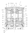
以下、本発明の実施形態について図面を参照して説明する。図1は、ポンプ装置の断面図である。図1に示すように、ポンプ装置2は、キャンドモータポンプである。しかしながら、ポンプ装置2は、防水処理が施されていれば、必ずしも、キャンドモータポンプに限定されない。キャンドモータポンプは、液体がその内部を通過する構造を有している。ポンプ装置2は、ポンプPと、このポンプPを駆動するためのモータ部Mと、から構成されている。ポンプPは、液体を移送するための羽根車20と、羽根車20が固定された回転軸(主軸)22と、羽根車20を収容するポンプケーシング24と、を備えている。
The following describes an embodiment of the present invention with reference to the drawings. FIG. 1 is a cross-sectional view of a pump device. As shown in FIG. 1, the
図1に示す実施形態では、ポンプPは、複数(より具体的には、6つ)の羽根車20を備えた多段ポンプである。一実施形態では、ポンプPは、単数の羽根車20を備えた単段ポンプであってもよい。ポンプ装置2は、直立姿勢で配置された立軸ポンプ装置であるが(図1の上下左右方向参照)、一実施形態では、ポンプ装置2は、横向き姿勢で配置された横軸ポンプ装置であってもよい。
In the embodiment shown in FIG. 1, the pump P is a multi-stage pump equipped with multiple (more specifically, six)
ポンプケーシング24の高圧側の開口部にはケーシングカバー25が固定されている。回転軸22はケーシングカバー25を貫通して延びている。ケーシングカバー25には、ポンプケーシング24内に吸い込まれた液体の一部をモータ部Mとの間で通過させる流通孔26が形成されている。後述するように、羽根車20の回転によって昇圧された液体の一部は、これら複数の流入孔26を通ってモータ部Mに導かれる。
A
ポンプ装置2は、回転軸22を回転させるモータ30と、回転軸22を回転可能に支持するすべり軸受31,32と、モータ30を収容するモータケーシング35と、を備えている。ケーシングカバー25は、モータケーシング35の構成要素の一部である。
The
モータ30は、回転軸22に固定されたモータロータ36と、モータロータ36の周囲に配置されたモータステータ37と、を備えている。モータステータ37は、ステータコア37aと、ステータコア37aに巻かれた複数のコイル37bと、を備えている。複数のコイル37bはモータロータ36を囲むように配置されている。
The
回転軸22は、モータ30の両側に配置されたすべり軸受31,32によって回転可能に支持されている。図1に示す実施形態では、すべり軸受31は、モータ30の下方に配置されており、すべり軸受32は、モータ30の上方に配置されている。すべり軸受31は、回転軸22のラジアル荷重およびアキシャル荷重を支持する軸受である。すべり軸受32は、ラジアル荷重を受けるが、アキシャル荷重を積極的には受けない。なお、ポンプ装置2の始動時には、すべり軸受32は、エンドカバー38(後述する)に押し付けられる場合がある。すべり軸受31とモータロータ36との間には、スラスト板33が配置されており、すべり軸受32とモータロータ36との間には、スラスト板34が配置されている。
The rotating
モータケーシング35は、すべり軸受31を支持するケーシングカバー25と、すべり軸受32を支持するエンドカバー38と、ケーシングカバー25とエンドカバー38との間に配置されたモータフレーム39と、を備えている。
The
モータフレーム39は、ケーシングカバー25およびエンドカバー38の両方に接続されている。ケーシングカバー25は、モータフレーム39の一方の開口端を閉じており、エンドカバー38は、モータフレーム39の他方の開口端を閉じている。エンドカバー38は、モータ30の反負荷側(本実施形態では、上方)に配置されており、ケーシングカバー25は、モータ30の負荷側(本実施形態では、下方)に配置されている。モータフレーム39の内周面には、モータステータ37が固定されている。
The
図1に示すように、モータロータ36とモータステータ37との間には、円筒状のキャン(ステータキャン)40がモータロータ36を取り囲むように配置されている。モータステータ37は、モータフレーム39とキャン40との間に配置されており、キャン40の外周面に固定されている。モータロータ36、モータステータ37、およびキャン40は同心状に配置されている。モータステータ37は、モータフレーム39、ケーシングカバー25、エンドカバー38、およびキャン40により形成されたステータ室SC内に配置されている。
As shown in FIG. 1, a cylindrical can (stator can) 40 is disposed between the
モータロータ36には、円筒状のキャン(ロータキャン)41が配置されている。キャン41は、モータロータ36を覆っており、キャン40に対向して配置されている。
A cylindrical can (rotor can) 41 is disposed on the
モータステータ37のコイル37bに電流を流すと、モータステータ37に磁界が形成され、この磁界により、モータロータ36が回転する。モータロータ36は、回転軸22を通じて羽根車20を回転させる。羽根車20が回転軸22とともに回転すると、液体は吸込口8からポンプケーシング24内に吸い込まれ、羽根車20の回転により昇圧された後、吐出口9から吐き出される。
When a current is passed through the
図2は、ポンプ装置2の運転時におけるポンプ装置2内の液体の流れを示す図である。図1および図2に示すように、ポンプ装置2は、回転軸22に固定され、かつ液体を流通孔26に導く循環羽根100と、循環羽根100の回転によって昇圧された液体が流れる循環流路をモータケーシング35との間に形成する循環カバー101と、を備えている。
Figure 2 is a diagram showing the flow of liquid within the
図1および図2に示す実施形態では、循環羽根100は、クローズド羽根であり、羽根車20に隣接する負荷側に配置されている。循環羽根100が回転軸22とともに回転すると、ポンプケーシング24内に吸い込まれた液体の一部は、ケーシングカバー25に形成された流通孔26を通ってモータ部Mに導かれる(図2の矢印参照)。ケーシングカバー25は、循環羽根100を収容するケーシング部102を有しており、循環羽根100は、羽根車20の回転によって昇圧された液体をさらに昇圧する。昇圧された液体の一部は、すべり軸受31と回転軸22との間の僅かな隙間を通過して、すべり軸受31を冷却および潤滑する。
In the embodiment shown in Figures 1 and 2, the
すべり軸受31とスラスト板33との間には、軸受105が配置されている。この軸受105は、液体の動圧を利用したすべり軸受(より具体的には、動圧軸受)である。軸受105は、互いに隣接して配置された回転側軸受体105aおよび固定側軸受体105bの組み合わせから構成される。回転側軸受体105aはスラスト板33に固定されており、固定側軸受体105bはケーシングカバー25に固定されている。回転側軸受体105aには、動圧を発生させるためのスパイラル溝(図示しない)が形成されている。
A
流入孔26を通過した液体は、キャン40に囲まれた空間C1を流れる。このように、空間C1を流れる液体は、モータ30を冷却する。空間C1を流れる液体の一部は、軸受105に導かれる。回転側軸受体105aが回転軸22とともに回転すると、回転側軸受体105aと固定側軸受体105bとの間に液体の動圧が発生する。軸受105は、この液体の動圧によって、ケーシングカバー25およびスラスト板33を非接触に支持する。
The liquid that passes through the
エンドカバー38は、キャン40の内部を流れる液体をモータケーシング35の外部に通過させる流通孔46を有している。本実施形態では、流通孔46は、エンドカバー38の中央に形成されている。キャン40の内部を流れる液体は、流通孔46を通じて、モータケーシング35の外部に流出する。このようにして、流通孔26,46を有するモータケーシング35は、液体の通過を許容する。液体の一部は、すべり軸受32と回転軸22との間の僅かな隙間を流れて、すべり軸受32を冷却および潤滑する。
The
循環カバー101は、モータケーシング35の全体を覆うカップ形状を有している。より具体的には、循環カバー101は、エンドカバー38に隣接して配置されたカバー部101aと、カバー部101aに接続され、モータフレーム39を取り囲むフレーム部101bと、を備えている。フレーム部101bは、ケーシングカバー25に接続されている。
The
カバー部101aとフレーム部101bとの間には、Oリングなどのシール部材110が配置されており、フレーム部101bとケーシングカバー25との間には、Oリングなどのシール部材111が配置されている。これらシール部材110,111は、循環流路を流れる液体の漏洩を防止する。循環流路は、空間C1と、モータフレーム39とフレーム部101bとの間の空間C2と、の間で循環する液体の流路である。
A
流通孔46を通じて循環カバー101内に流入した液体は、エンドカバー38とカバー部101aとの間の隙間を通過し、モータフレーム39とフレーム部101bとの間の隙間(すなわち、空間C2)を通過する。空間C2を流れる液体は、モータ30を冷却する。ケーシングカバー25は、流通孔26の外側に配置された流通孔56を備えており、流通孔56は空間C2に連通している。したがって、空間C2を流れる液体は、流通孔56を通じてポンプ部Pに戻され、循環羽根100の回転によって、再び、流通孔26を通じて空間C1に流入する。
The liquid that flows into the
このように、本実施形態では、ポンプ装置2は、空間C1と空間C2との間で液体を循環させる構造を有しているため、モータ30の、液体との接触面積を増加させることができる。結果として、モータ30の冷却効果は向上する。さらに、本実施形態によれば、回転軸22の軸線CL方向に沿った貫通孔を回転軸22に形成する必要はない。さらに、本実施形態によれば、ポンプ装置2は、液体をポンプ部Pの吐出側に戻し、ポンプ部Pの吸込側に戻す構成を有していない。したがって、本来のポンプ性能は、戻された液体による影響を受けない。
In this manner, in this embodiment, the
本実施形態によれば、モータケーシング35に形成された流通孔26,46,56と、循環羽根100と、モータケーシング35を覆う循環カバー101と、を設けるだけの簡単な構造で液体の循環流路を形成することができる。
According to this embodiment, a liquid circulation flow path can be formed with a simple structure that only requires the provision of flow holes 26, 46, 56 formed in the
図3は、回転軸22に固定されたバランスディスクを示す図である。図3に示すように、ポンプ装置2は、回転軸22に固定され、かつ羽根車20に作用する軸方向推力を打ち消すバランスディスク120を備えてもよい。
Figure 3 is a diagram showing a balance disk fixed to the
回転軸22には、回転する羽根車20の吸込み側と吐出し側との圧力差に起因して、吐出し側から吸込み側へ軸方向推力が作用する。バランスディスク120は、軸方向推力に対して反対方向のバランス推力を発生させることによって軸方向推力とバランス推力とを釣り合わせる。図3に示すように、バランスディスク120は、モータ30を挟んで羽根車20とは反対側の反負荷側に配置されており、回転軸22の端部に固定されている。図3に示す実施形態では、バランスディスク120は、受け皿形状を有している。
An axial thrust acts on the
バランスディスク120は、空間C1を流れる液体の流れ方向において、流通孔46の下流側に配置されている。したがって、流通孔46を通過する液体は、バランスディスク120に衝突し、バランスディスク120に作用する液体の力によってバランスディスク120は、バランス推力を発生させる。
The
流通孔46を通過した液体の一部は、バランスディスク120とエンドカバー38との間の隙間を通過して、カバー部101aとエンドカバー38との間の循環流路を流れる。大きなバランス推力を発生させるために、バランスディスク120とエンドカバー38との間の隙間は小さい。より具体的には、この隙間は、軸方向推力とバランス推力とを釣り合わせることが可能な程度の大きさを有している。
A portion of the liquid that passes through the
大きなバランス推力を発生させるために、バランスディスク120の直径は循環羽根100の直径よりも大きいことが好ましい。このような構成により、バランスディスク120の受圧面積は循環羽根100の受圧面積よりも大きくなるため、バランスディスク120は循環羽根100に作用する圧力差に起因して発生する軸方向推力を打ち消すことができる。
To generate a large balance thrust, it is preferable that the diameter of the
図3に示すように、ポンプ装置2は、バランスディスク120の軸線CL方向への移動距離を検出する距離センサ130と、距離センサ130に接続された摩耗監視装置135と、を備えている。
As shown in FIG. 3, the
距離センサ130は、検出素子(より具体的には、ホール素子)130a,130bを備えている。検出素子130a,130bは対向して配置されており、検出素子130aは循環カバー101のカバー部101aに取り付けられており、検出素子130bはバランスディスク120に取り付けられている。一実施形態では、検出素子130aはエンドカバー38に取り付けられてもよい。
The
距離センサ130は、バランスディスク120とカバー部101aとの間の距離の変化を検出する。言い換えれば、距離センサ130は、バランスディスク120の軸線CL方向の移動距離を検出する。
The
摩耗監視装置135は、少なくとも1台のコンピュータから構成される。摩耗監視装置135は、プログラムが格納された記憶装置135aと、プログラムに含まれる命令に従って演算を実行する演算装置135bと、を備えている。演算装置135bは、記憶装置135aに格納されているプログラムに含まれている命令に従って演算を行うCPU(中央処理装置)またはGPU(グラフィックプロセッシングユニット)などを含む。記憶装置135aは、演算装置135bがアクセス可能な主記憶装置(例えばランダムアクセスメモリ)と、データおよびプログラムを格納する補助記憶装置(例えば、ハードディスクドライブまたはソリッドステートドライブ)を備えている。
The
図4は、摩耗監視装置135によるすべり軸受31,32の摩耗を決定するフローを示す図である。摩耗監視装置135は、距離センサ130によって検出されたバランスディスク120の移動距離に基づいて、回転軸22を回転自在に支持するすべり軸受31,32の摩耗を監視する。
Figure 4 shows the flow of determining the wear of the
図4のステップS101に示すように、摩耗監視装置135は、距離センサ130の検出値を常時監視する。記憶装置135aは、すべり軸受31,32の摩耗量に相当するしきい値を記憶している。演算装置135bは、距離センサ130の検出値と記憶装置135aに記憶されたしきい値とを比較して(図4のステップS102参照)、検出値がしきい値よりも大きい場合(図4のステップS102の「YES」参照)、すべり軸受31,32の摩耗を決定する(図4のステップS103参照)。この場合、摩耗監視装置135は、アラームを発報してもよい。検出値がしきい値よりも小さい場合(図4のステップS102の「NO」参照)、摩耗監視装置135は、距離センサ130の検出値の監視を継続する。
As shown in step S101 of FIG. 4, the
上述したように、検出素子130aはエンドカバー38に取り付けられてもよい。この場合、演算装置135bは、距離センサ130の検出値と記憶装置135aに記憶されたしきい値とを比較して、検出値がしきい値よりも小さい場合に、すべり軸受31,32の摩耗を決定する。このしきい値は、上記しきい値と同一であってもよく、異なってもよい。
As described above, the
図3に示すように、バランスディスク120は、バランスディスク120に衝突する液体に含まれる空気を通過させる空気抜き孔121を有してもよい。図3に示す実施形態では、複数(図3では、2つ)の空気抜き孔121が設けられているが、単一の空気抜き孔121が設けられてもよい。
As shown in FIG. 3, the
空気抜き孔121は、流通孔46を通過する液体に含まれる空気がモータケーシング35の内部に溜まることを防止する。比重の小さな空気は、バランスディスク120の回転によって、バランスディスク120の中心側(すなわち、回転軸22の近傍)に移動する。したがって、空気抜き孔121は、バランスディスク120の中心側に配置されていることが好ましい。
The
図5は、バランスディスク120の他の実施形態を示す図である。図5に示すように、バランスディスク120は、バランスディスク120に衝突する液体の力が作用する方向に傾斜するテーパー形状を有してもよい。言い換えれば、バランスディスク120は、回転軸22から離間する方向に傾斜するテーパー形状を有している。
Figure 5 is a diagram showing another embodiment of the
このように、バランスディスク120はテーパー形状を有しているため、流通孔46を通過する液体に含まれる空気は、バランスディスク120に沿って外側に移動し、カバー部101aとエンドカバー38との間の循環流路に流れる。結果として、バランスディスク120は、空気がモータケーシング35の内部に溜まることを防止する。このような構造により、空気抜き孔121を設ける必要はなく、バランスディスク120に作用する圧力の損失を抑制することができる。結果として、バランスディスク120は、より大きなバランス推力を発生させることができる。
As described above, because the
上述した実施形態では、循環羽根100は、クローズド羽根であるが、循環羽根100は、クローズド羽根に限定されず、他の羽根形状を有してもよい。以下、循環羽根100がカスケード羽根である実施形態について説明する。
In the above-described embodiment, the
図6は、カスケード羽根としての循環羽根を備えたポンプ装置を示す図である。図7は、ケーシング部に収容された循環羽根を示す図である。図6および図7に示すように、循環羽根100は、小流量でかつ高揚程を実現可能なカスケード羽根である。循環羽根100は、回転軸22の周方向に沿って等間隔に配置された複数の溝部150を備えている。これら複数の溝部150は、循環羽根100の両面に形成されている。
Figure 6 is a diagram showing a pump device equipped with a circulation impeller as a cascade impeller. Figure 7 is a diagram showing a circulation impeller housed in a casing section. As shown in Figures 6 and 7, the
ケーシング部102は、吸込孔151および吐出孔152を有している。循環羽根100が回転軸22とともに回転すると、液体が吸込孔151を通じてケーシング部102内に流入し、循環羽根100の回転によって昇圧される。その後、昇圧された液体は吐出孔152を通じて回転軸22側に流れ(図6の矢印参照)、スムーズにすべり軸受31に導かれる。結果として、すべり軸受31を効果的に潤滑することができる。
The
このように、カスケード羽根としての循環羽根100を設けることにより、循環羽根100のサイズを小さくすることができ、かつ、より液体を昇圧することができる。さらに、循環羽根100自体はバランスしており、循環羽根100には、軸方向推力は発生しない。したがって、バランスディスク120は、自身に発生するバランス推力と軸方向推力を効果的に打ち消すことができる。
In this way, by providing the
図8は、ポンプ装置2の他の実施形態を示す図である。以下に示す実施形態において、上述した実施形態と同一の構成については、その説明を省略する。図8に示すように、循環羽根100は、モータ30を挟んで羽根車20とは反対側の反負荷側に配置されている。図8に示す実施形態では、循環羽根100は、クローズド羽根であり、モータ30に関して、羽根車20とは対称的に(すなわち、逆向き)配置されている(図1参照)。ポンプ装置2は、バランスディスク120を備えておらず、循環羽根100は、回転軸22の端部に固定されている。一実施形態では、循環羽根100は、カスケード羽根であってもよい。
Figure 8 is a diagram showing another embodiment of the
循環羽根100は、羽根車20とは逆向きに配置されているため、バランスディスク120と同様に、バランス推力を発生させることができ、軸方向推力を軽減することができる。図8に示すように、羽根車20によって昇圧された液体は、循環羽根100の回転によって、流通孔56を通じて空間C2に流入する。その後、液体は、空間C2を通過し、流通孔46を通じてモータケーシング35内に流入する。図8に示す実施形態では、エンドカバー38には、ライナーリング160が固定されており、流通孔46はライナーリング160に形成されている。ライナーリング160は、外れないように、カバー部101aによって支持されている。
Since the
モータケーシング35内に流入した液体は、循環羽根100によって再度昇圧され、空間C1を通過する。その後、液体は、流通孔26を通過して、ポンプ部Pに戻される。本実施形態においても、モータケーシング35に形成された流通孔26,46,56と、循環羽根100と、モータケーシング35を覆う循環カバー101と、を設けるだけの簡単な構造で液体の循環流路を形成することができる。
The liquid that flows into the
上述した実施形態は、本発明が属する技術分野における通常の知識を有する者が本発明を実施できることを目的として記載されたものである。上記実施形態の種々の変形例は、当業者であれば当然になしうることであり、本発明の技術的思想は他の実施形態にも適用しうることである。したがって、本発明は、記載された実施形態に限定されることはなく、特許請求の範囲によって定義される技術的思想に従った最も広い範囲に解釈されるものである。 The above-described embodiments have been described with the aim of enabling a person having ordinary knowledge in the technical field to which the present invention pertains to practice the present invention. Various modifications of the above-described embodiments would naturally be possible for a person skilled in the art, and the technical concept of the present invention can be applied to other embodiments. Therefore, the present invention is not limited to the described embodiments, but is to be interpreted in the broadest scope in accordance with the technical concept defined by the scope of the claims.
2 ポンプ装置
8 吸込口
9 吐出口
20 羽根車
22 回転軸
24 ポンプケーシング
25 ケーシングカバー
26 流通孔
30 モータ
31,32 すべり軸受
33,34 スラスト板
35 モータケーシング
36 モータロータ
37 モータステータ
37a ステータコア
37b コイル
38 エンドカバー
39 モータフレーム
40,41 キャン
46 流通孔
56 流通孔
100 循環羽根
101 循環カバー
101a カバー部
101b フレーム部
102 ケーシング部
105 軸受
105a 回転側軸受体
105b 固定側軸受体
110 シール部材
111 シール部材
120 バランスディスク
121 空気抜き孔
130 距離センサ
130a,130b 検出素子
135 摩耗監視装置
135a 記憶装置
135b 演算装置
150 溝部
151 吸込孔
152 吐出孔
160 ライナーリング
Claims (12)
前記羽根車を固定する回転軸と、
前記羽根車を収容するポンプケーシングと、
前記回転軸に固定されたモータロータおよび前記モータロータの周囲に配置されたモータステータから構成された、前記回転軸を回転するモータと、
前記モータを収容するモータケーシングと、
前記モータケーシングに形成された、液体を通過させる流通孔と、
前記回転軸に固定され、かつ液体を前記流通孔に導く循環羽根と、
前記循環羽根の回転によって昇圧された液体が流れる循環流路を前記モータケーシングとの間に形成する循環カバーと、を備えており、
前記モータケーシングは、
前記ポンプケーシングに固定されたケーシングカバーと、
前記モータを挟んで、前記ケーシングカバーの反対側に配置されたエンドカバーと、を備えており、
前記流通孔は、前記ケーシングカバーおよび前記エンドカバーのそれぞれに形成されており、
前記循環カバーは、
前記エンドカバーに隣接して配置されたカバー部と、
前記カバー部に接続され、前記モータケーシングのモータフレームを取り囲むフレーム部と、を備えており、
前記循環流路は、前記モータロータと前記モータステータとの間の第1空間と、前記フレーム部と前記モータフレームとの間の第2空間と、の間で循環する液体の流路であり、
前記循環羽根は、前記第1空間と、前記エンドカバーの中央に形成された前記流通孔と、を通じて、前記モータケーシングの外部に流出した液体を前記カバー部に衝突させて、放射状に流出する液体を前記第2空間に流入させる、ポンプ装置。 an impeller for transporting liquid;
A rotating shaft to which the impeller is fixed;
a pump casing that houses the impeller;
a motor that rotates the rotary shaft and is configured with a motor rotor fixed to the rotary shaft and a motor stator arranged around the motor rotor;
a motor casing that houses the motor;
a flow hole formed in the motor casing for passing a liquid;
a circulation blade fixed to the rotating shaft and configured to guide the liquid to the flow hole;
a circulation cover that forms a circulation flow path between the circulation cover and the motor casing, through which the liquid pressurized by the rotation of the circulation blade flows ;
The motor casing includes:
a casing cover fixed to the pump casing;
an end cover disposed on the opposite side of the casing cover across the motor,
the communication hole is formed in each of the casing cover and the end cover,
The circulation cover is
A cover portion disposed adjacent to the end cover;
a frame portion connected to the cover portion and surrounding a motor frame of the motor casing,
the circulation flow path is a flow path for liquid circulating between a first space between the motor rotor and the motor stator and a second space between the frame portion and the motor frame,
The circulation blade causes liquid that has flowed out of the motor casing through the first space and the circulation hole formed in the center of the end cover to collide with the cover portion, and causes the liquid flowing out radially to flow into the second space.
前記ポンプ装置は、前記回転軸に固定され、かつ前記羽根車に作用する軸方向推力を打ち消すバランスディスクを備えている、請求項1に記載のポンプ装置。 The circulation blades are disposed on a load side adjacent to the impeller,
2. The pump device according to claim 1 , further comprising a balance disk fixed to the rotating shaft and configured to counteract an axial thrust acting on the impeller.
前記バランスディスクの軸線方向への移動距離を検出する距離センサと、
前記距離センサに接続された摩耗監視装置と、を備えており、
前記摩耗監視装置は、前記距離センサによって検出された前記バランスディスクの移動距離に基づいて、前記回転軸を支持する軸受の摩耗を監視する、請求項3~請求項6のいずれか一項に記載のポンプ装置。 The pump device includes:
a distance sensor for detecting a moving distance of the balance disc in an axial direction;
a wear monitor connected to the distance sensor,
The pump apparatus according to any one of claims 3 to 6 , wherein the wear monitoring device monitors wear of a bearing that supports the rotating shaft based on a moving distance of the balance disc detected by the distance sensor.
前記ケーシング部は、The casing portion includes:
前記循環羽根の回転によって、前記液体を前記ケーシング部の内部に流入させる吸込孔と、a suction hole that causes the liquid to flow into the inside of the casing portion by rotation of the circulation blade;
前記循環羽根の回転によって昇圧された前記液体を、前記回転軸を支持する軸受に導くための吐出孔と、を有している、請求項1~請求項11のいずれか一項に記載のポンプ装置。The pump device according to any one of claims 1 to 11, further comprising: a discharge hole for guiding the liquid pressurized by rotation of the circulation blade to a bearing supporting the rotating shaft.
Priority Applications (1)
| Application Number | Priority Date | Filing Date | Title |
|---|---|---|---|
| JP2020139862A JP7536552B2 (en) | 2020-08-21 | 2020-08-21 | Pumping equipment |
Applications Claiming Priority (1)
| Application Number | Priority Date | Filing Date | Title |
|---|---|---|---|
| JP2020139862A JP7536552B2 (en) | 2020-08-21 | 2020-08-21 | Pumping equipment |
Publications (2)
| Publication Number | Publication Date |
|---|---|
| JP2022035496A JP2022035496A (en) | 2022-03-04 |
| JP7536552B2 true JP7536552B2 (en) | 2024-08-20 |
Family
ID=80443448
Family Applications (1)
| Application Number | Title | Priority Date | Filing Date |
|---|---|---|---|
| JP2020139862A Active JP7536552B2 (en) | 2020-08-21 | 2020-08-21 | Pumping equipment |
Country Status (1)
| Country | Link |
|---|---|
| JP (1) | JP7536552B2 (en) |
Citations (4)
| Publication number | Priority date | Publication date | Assignee | Title |
|---|---|---|---|---|
| JP2000154795A (en) | 1998-11-19 | 2000-06-06 | Mitsubishi Heavy Ind Ltd | Balance disc device of centrifugal pump |
| JP2001323889A (en) | 2000-03-06 | 2001-11-22 | Ebara Corp | All around flow type motor pump |
| CN106194769A (en) | 2016-08-31 | 2016-12-07 | 池泉 | A kind of quiet centrifugal pump |
| JP2017180781A (en) | 2016-03-31 | 2017-10-05 | 株式会社荏原製作所 | Shaft assembly, motor shaft, motor, motor pump, and manufacturing method of shaft assembly |
Family Cites Families (5)
| Publication number | Priority date | Publication date | Assignee | Title |
|---|---|---|---|---|
| JPS5943695U (en) * | 1982-09-17 | 1984-03-22 | 株式会社荏原製作所 | submersible motor pump |
| JPH0743221U (en) * | 1990-12-20 | 1995-08-18 | 株式会社帝国電機製作所 | Groundless pump |
| JPH087142Y2 (en) * | 1991-02-15 | 1996-03-04 | 日機装株式会社 | Bearing wear monitoring device |
| JPH06249182A (en) * | 1993-02-22 | 1994-09-06 | Hitachi Ltd | Canned motor-type pump |
| JPH0828484A (en) * | 1994-07-15 | 1996-01-30 | Kubota Corp | pump |
-
2020
- 2020-08-21 JP JP2020139862A patent/JP7536552B2/en active Active
Patent Citations (4)
| Publication number | Priority date | Publication date | Assignee | Title |
|---|---|---|---|---|
| JP2000154795A (en) | 1998-11-19 | 2000-06-06 | Mitsubishi Heavy Ind Ltd | Balance disc device of centrifugal pump |
| JP2001323889A (en) | 2000-03-06 | 2001-11-22 | Ebara Corp | All around flow type motor pump |
| JP2017180781A (en) | 2016-03-31 | 2017-10-05 | 株式会社荏原製作所 | Shaft assembly, motor shaft, motor, motor pump, and manufacturing method of shaft assembly |
| CN106194769A (en) | 2016-08-31 | 2016-12-07 | 池泉 | A kind of quiet centrifugal pump |
Also Published As
| Publication number | Publication date |
|---|---|
| JP2022035496A (en) | 2022-03-04 |
Similar Documents
| Publication | Publication Date | Title |
|---|---|---|
| US6129507A (en) | Method and device for reducing axial thrust in rotary machines and a centrifugal pump using same | |
| US6254361B1 (en) | Shaftless canned rotor inline pipe pump | |
| JP2012007592A (en) | Seal device, and fluid machine provided with the same | |
| JP2006508315A (en) | Ball bearings and vacuum pumps equipped with this type of bearing | |
| JP6747354B2 (en) | Centrifugal compressor | |
| EP3922859B1 (en) | Centrifugal compressor | |
| KR102281117B1 (en) | Turbo compressor | |
| WO2012001997A1 (en) | Seal device and fluid machinery provided with same | |
| JP7536552B2 (en) | Pumping equipment | |
| JP2017032118A (en) | Shaft sealing device and rotary machine | |
| JPH02196191A (en) | Electric motor driven pump | |
| US10240609B2 (en) | Screw pump and impeller fan assemblies and method of operating | |
| JP2015175240A (en) | Bearing device and vertical shaft pump including the same | |
| JP6126850B2 (en) | Shaft seal device and pump device | |
| JP6325969B2 (en) | Submersible electric pump with oil return mechanism | |
| CN119755126B (en) | An axial force balancing mechanism for a multistage centrifugal pump and the multistage centrifugal pump | |
| US10669850B2 (en) | Impeller-type liquid ring compressor | |
| JP6591601B2 (en) | Submersible electric pump with oil return mechanism | |
| KR102333286B1 (en) | The pump for the cryogenic fluid circulation with the fluid bearing | |
| CN216950876U (en) | Rare earth permanent magnet driven single-stage single-suction centrifugal pump | |
| CN114526240B (en) | Rare earth permanent magnet driven single-stage single-suction centrifugal pump, flushing and self-lubricating method | |
| JPH02173393A (en) | Axial thrust relieving device for axial flow pump | |
| KR100558054B1 (en) | Integral reactor SMAART main coolant pump | |
| JP6746277B2 (en) | pump | |
| JP2017009043A (en) | Bearing device and pump |
Legal Events
| Date | Code | Title | Description |
|---|---|---|---|
| A621 | Written request for application examination |
Free format text: JAPANESE INTERMEDIATE CODE: A621 Effective date: 20230314 |
|
| A977 | Report on retrieval |
Free format text: JAPANESE INTERMEDIATE CODE: A971007 Effective date: 20230927 |
|
| A131 | Notification of reasons for refusal |
Free format text: JAPANESE INTERMEDIATE CODE: A131 Effective date: 20231003 |
|
| A601 | Written request for extension of time |
Free format text: JAPANESE INTERMEDIATE CODE: A601 Effective date: 20231204 |
|
| A521 | Request for written amendment filed |
Free format text: JAPANESE INTERMEDIATE CODE: A523 Effective date: 20231211 |
|
| A131 | Notification of reasons for refusal |
Free format text: JAPANESE INTERMEDIATE CODE: A131 Effective date: 20240305 |
|
| A601 | Written request for extension of time |
Free format text: JAPANESE INTERMEDIATE CODE: A601 Effective date: 20240501 |
|
| A521 | Request for written amendment filed |
Free format text: JAPANESE INTERMEDIATE CODE: A523 Effective date: 20240520 |
|
| TRDD | Decision of grant or rejection written | ||
| A01 | Written decision to grant a patent or to grant a registration (utility model) |
Free format text: JAPANESE INTERMEDIATE CODE: A01 Effective date: 20240806 |
|
| A61 | First payment of annual fees (during grant procedure) |
Free format text: JAPANESE INTERMEDIATE CODE: A61 Effective date: 20240807 |
|
| R150 | Certificate of patent or registration of utility model |
Ref document number: 7536552 Country of ref document: JP Free format text: JAPANESE INTERMEDIATE CODE: R150 |