JP7488331B2 - Grip and barrel assembly for syringe barrel, and syringe - Google Patents
Grip and barrel assembly for syringe barrel, and syringe Download PDFInfo
- Publication number
- JP7488331B2 JP7488331B2 JP2022509347A JP2022509347A JP7488331B2 JP 7488331 B2 JP7488331 B2 JP 7488331B2 JP 2022509347 A JP2022509347 A JP 2022509347A JP 2022509347 A JP2022509347 A JP 2022509347A JP 7488331 B2 JP7488331 B2 JP 7488331B2
- Authority
- JP
- Japan
- Prior art keywords
- flange
- grip
- barrel
- pair
- syringe
- Prior art date
- Legal status (The legal status is an assumption and is not a legal conclusion. Google has not performed a legal analysis and makes no representation as to the accuracy of the status listed.)
- Active
Links
Images


Classifications
-
- A—HUMAN NECESSITIES
- A61—MEDICAL OR VETERINARY SCIENCE; HYGIENE
- A61M—DEVICES FOR INTRODUCING MEDIA INTO, OR ONTO, THE BODY; DEVICES FOR TRANSDUCING BODY MEDIA OR FOR TAKING MEDIA FROM THE BODY; DEVICES FOR PRODUCING OR ENDING SLEEP OR STUPOR
- A61M5/00—Devices for bringing media into the body in a subcutaneous, intra-vascular or intramuscular way; Accessories therefor, e.g. filling or cleaning devices, arm-rests
- A61M5/178—Syringes
- A61M5/31—Details
- A61M5/3129—Syringe barrels
- A61M5/3137—Specially designed finger grip means, e.g. for easy manipulation of the syringe rod
- A61M2005/3139—Finger grips not integrally formed with the syringe barrel, e.g. using adapter with finger grips
-
- A—HUMAN NECESSITIES
- A61—MEDICAL OR VETERINARY SCIENCE; HYGIENE
- A61M—DEVICES FOR INTRODUCING MEDIA INTO, OR ONTO, THE BODY; DEVICES FOR TRANSDUCING BODY MEDIA OR FOR TAKING MEDIA FROM THE BODY; DEVICES FOR PRODUCING OR ENDING SLEEP OR STUPOR
- A61M5/00—Devices for bringing media into the body in a subcutaneous, intra-vascular or intramuscular way; Accessories therefor, e.g. filling or cleaning devices, arm-rests
- A61M5/001—Apparatus specially adapted for cleaning or sterilising syringes or needles
Landscapes
- Health & Medical Sciences (AREA)
- Vascular Medicine (AREA)
- Engineering & Computer Science (AREA)
- Anesthesiology (AREA)
- Biomedical Technology (AREA)
- Heart & Thoracic Surgery (AREA)
- Hematology (AREA)
- Life Sciences & Earth Sciences (AREA)
- Animal Behavior & Ethology (AREA)
- General Health & Medical Sciences (AREA)
- Public Health (AREA)
- Veterinary Medicine (AREA)
- Infusion, Injection, And Reservoir Apparatuses (AREA)
- Apparatus For Disinfection Or Sterilisation (AREA)
Description
本発明は、注射器用バレルに装着される注射器バレル用グリップ、注射器バレル用グリップを備えるバレル組立体およびシリンジに関する。The present invention relates to a syringe barrel grip that is attached to a syringe barrel, a barrel assembly including a syringe barrel grip, and a syringe.
一部の薬剤充填済みシリンジ(プレフィルドシリンジ)では、医療過誤防止のため、ガスケットに結合されていないプランジャが使用されている。このようなプレフィルドシリンジにおいては、プランジャが基端側に移動してバレル内から脱落することを防ぐためのクリップ(バックストップ)が装着される(特許文献1)。Some prefilled syringes use a plunger that is not connected to a gasket to prevent medical errors. In such prefilled syringes, a clip (backstop) is attached to prevent the plunger from moving toward the base end and falling out of the barrel (Patent Document 1).
また、シリンジの把持および操作を容易にするために、バレルの基端部に、外方に突出する指掛け部を備えたクリップ(グリップ)を装着することも知られている(特許文献2)。It is also known to attach a clip (grip) with an outwardly protruding finger hook to the base end of the barrel to make it easier to grasp and operate the syringe (Patent Document 2).
これらのクリップは、シリンジの操作中にがたついたり外れたりしないように、筒状の嵌合部においてバレルの外周面に嵌合され、シリンジに強固に装着されている。These clips are firmly attached to the syringe by fitting to the outer surface of the barrel at a cylindrical fitting portion to prevent rattling or coming off during operation of the syringe.
近年、眼科用途などにおいては、投与する薬剤および薬剤に接する部分だけでなく、グリップを含めたプレフィルドシリンジ全体のより高い無菌性が求められている。そこで、本発明者らは、グリップが装着されたプレフィルドシリンジに対して、過酸化水素滅菌やEOG滅菌、NO2滅菌などの熱負荷が少ない表面滅菌法の適用を検討した。これらの表面滅菌法はガス(滅菌用気体)による滅菌であり、より高い無菌性を実現するためには、プレフィルドシリンジの表面のより広い範囲に、滅菌用のガスが接触することが好ましい。 In recent years, in ophthalmic applications, not only the medicine to be administered and the part that contacts the medicine, but also the whole prefilled syringe including the grip is required to have higher sterility.Therefore, the present inventors have studied the application of surface sterilization methods with low thermal load, such as hydrogen peroxide sterilization, EOG sterilization, and NO2 sterilization, to the prefilled syringe with the grip.These surface sterilization methods are sterilization by gas (sterilization gas), and in order to achieve higher sterility, it is preferable that the sterilization gas contacts a wider area of the surface of the prefilled syringe.
そこで、本発明は、注射器用バレルに装着された状態で、操作性が良好で、かつ、より高い無菌性を実現できる注射器バレル用グリップ、ならびにそのような注射器バレル用グリップを備えるバレル組立体およびシリンジを提供するものである。Therefore, the present invention provides a syringe barrel grip that, when attached to a syringe barrel, provides good operability and achieves higher sterility, as well as a barrel assembly and a syringe that include such a syringe barrel grip.
上記目的を達成するものは、以下のものである。
筒状本体と、前記筒状本体に設けられ、外方に突出し、かつ互いに平行に向かい合う一対のフランジストレート部が形成されているフランジとを備える注射器用バレルに装着される注射器バレル用グリップであって、
前記グリップは、前記フランジを収納するフランジ収納部を備え、
前記フランジ収納部は、前記グリップの側面に形成された側面開口と、前記側面開口より前記グリップの内部方向に延びるフランジ挿入部と、前記フランジ挿入部と連通し、前記グリップの内部に延び、前記フランジ挿入部に前記フランジが収納された状態にて、前記バレルを所定角度回転させることにより、前記フランジが進入し、進入した前記フランジと前記グリップとの相対的な回動を規制するフランジ回動規制部とを備え、
前記フランジ挿入部は、前記一対のフランジストレート部より若干幅が広い第1の一対のグリップストレート部を備え、前記フランジ回動規制部は、前記一対のフランジストレート部より若干幅が広く、かつ、前記第1の一対のグリップストレート部に対して、斜めとなっている第2の一対のグリップストレート部を備え、
前記フランジが、前記フランジ回動規制部に収納された状態において、前記一対のフランジストレート部の前方側は、前記第2の一対のグリップストレート部内に位置し、前記一対のフランジストレート部の後方側は、前記第1の一対のグリップストレート部内に位置し、
かつ、前記バレルの前記フランジが、前記グリップの前記フランジ回動規制部に収納された状態において、前記グリップの下部内周面は、前記バレルと接触せず、前記グリップの下部内周面と前記バレル間に滅菌用気体を流入させるための空隙を備えている注射器バレル用グリップ。
The above objectives are achieved by the following:
A syringe barrel grip to be attached to a syringe barrel including a cylindrical body and a flange provided on the cylindrical body, the flange protruding outward and including a pair of flange straight portions facing each other in parallel, the grip comprising:
The grip includes a flange housing portion that houses the flange,
The flange housing portion includes a side opening formed on a side surface of the grip, a flange insertion portion extending from the side opening toward the inside of the grip, and a flange rotation restricting portion communicating with the flange insertion portion and extending into the inside of the grip, the flange entering the flange by rotating the barrel by a predetermined angle with the flange housed in the flange insertion portion, and restricting relative rotation between the entered flange and the grip,
the flange insertion portion includes a first pair of grip straight portions that are slightly wider than the pair of flange straight portions, and the flange rotation restricting portion includes a second pair of grip straight portions that are slightly wider than the pair of flange straight portions and are inclined with respect to the first pair of grip straight portions,
when the flange is housed in the flange rotation restricting portion, a front side of the pair of flange straight portions is located within the second pair of grip straight portions, and a rear side of the pair of flange straight portions is located within the first pair of grip straight portions,
and a grip for a syringe barrel, the grip having a lower inner circumferential surface that does not come into contact with the barrel when the flange of the barrel is housed in the flange rotation regulating portion of the grip, and a gap for allowing a sterilization gas to flow between the lower inner circumferential surface of the grip and the barrel.
また、上記目的を達成するものは、以下のものである。
筒状本体と、前記筒状本体の基端に設けられ、外方に突出し、かつ互いに平行に向かい合う一対のフランジストレート部が形成されているフランジとを備える注射器用バレルと、前記バレルに装着された上記の注射器バレル用グリップとを備えるバレル組立体。
The above object is also achieved by the following:
a syringe barrel including a cylindrical body, and a flange provided at a base end of the cylindrical body, the flange protruding outward and having a pair of flange straight portions facing each other in parallel, and the syringe barrel grip as described above attached to the barrel.
また、上記目的を達成するものは、以下のものである。
上記のバレル組立体と、前記バレル内に摺動可能に収納されたガスケットと、前記ガスケット移動用のプランジャとを備えるシリンジ。
The above object is also achieved by the following:
A syringe comprising the above barrel assembly, a gasket slidably housed within the barrel, and a plunger for moving the gasket.
本発明の注射器バレル用グリップ、ならびにそのような注射器バレル用グリップを備えるバレル組立体およびシリンジを図面に示した実施例を用いて説明する。
なお、本実施例においては、図1における上側(注射器用バレル20のフランジ22が形成されている側)を基端側または上側とし、図1における下側(注射器用バレル20のノズル部23が設けられている側)を先端側または下側とし、図1における上下方向を軸方向(注射器用バレル20や筒状本体21の軸方向)として説明する。
DETAILED DESCRIPTION OF THE PREFERRED EMBODIMENTS A syringe barrel grip of the present invention, and a barrel assembly and a syringe including such a syringe barrel grip, will now be described with reference to the embodiments shown in the drawings.
In this embodiment, the upper side in FIG. 1 (the side on which
本発明のシリンジ1は、図1ないし図6に示されるように、注射器用バレル20(以下、単にバレル20とも言う)と、バレル20に装着された注射器バレル用グリップ30(以下、単にグリップ30とも言う)とを備えるバレル組立体2と、バレル20内に摺動可能に収納されたガスケット11と、ガスケット11移動用のプランジャ12とを備える。As shown in Figures 1 to 6, the
バレル20は、筒状本体21と、筒状本体21に設けられ、外方(バレル20の軸方向に直交する方向)に突出し、かつ互いに平行に向かい合う一対のフランジストレート部24,24(幅w)が形成されているフランジ22(厚さt)とを備える。本実施例では、バレル20の筒状本体21は、全体において、その軸方向に直交する平面による断面において、外形および内形が円形(円環形状)となっている。バレル20の先端部には、薬剤吐出用の先端開口部(ノズル部)23が設けられている。
また、バレル20は、ノズル部23の基端側部分を被包するカラー25を備えている。カラー25の内面には、バレル側螺合部(雌形螺合部)が形成されている。
ノズル部23はシールキャップ13により封止されており、バレル20内に収納された薬剤60の漏出が防止されるとともに、無菌充填された薬剤60が外気と触れることを防止している。
The
The
The
バレル20の構成材料としては、例えば、ポリエチレン、ポリプロピレンなどのポリオレフィン、ポリスチレン、ポリアミド、ポリカーボネート、ポリ塩化ビニル、ポリ-(4-メチルペンテン-1)、アクリル樹脂、アクリロニトリル-ブタジエン-スチレン共重合体、ポリエチレンテレフタレート等のポリエステル、環状ポリオレフィンポリマー、環状オレフィンコポリマーのような各種樹脂が挙げられるが、その中でも成形が容易で耐熱性があることから、ポリプロピレン、環状ポリオレフィンポリマー、環状オレフィンコポリマーのような樹脂が好ましい。なお、内部に充填された薬液を外側から目視にて確認できるように透明性が高く、高圧蒸気滅菌に耐えられる耐熱性を有する環状オレフィンポリマー、環状オレフィンコポリマーが、バレル20の形成材料として特に好ましい。
Examples of materials that can be used to form the
シールキャップ13は、バレル20のノズル部23を収納する基端側中空部を有する本体部18と、本体部18内に収納され、基端側中空部の先端部に配置されたシール部材19とを有する。また、基端側中空部の外面には、カラー25の内面に形成された、バレル側螺合部(雌形螺合部)と螺合可能なキャップ側螺合部(雄形螺合部)が形成されている。The
シールキャップの形成材料としては、例えば、ポリプロピレン、ポリエチレン、ポリスチレン、ポリアミド、ポリカーボネート、ポリ塩化ビニル、ポリ-(4-メチルペンテン-1)、アクリル樹脂、アクリロニトリル-ブタジエン-スチレン共重合体、ポリエチレンテレフタレートなどのポリエステル、環状ポリオレフィンのような各種樹脂が挙げられるが、その中でも成形が容易で耐熱性があることから、ポリプロピレン、環状ポリオレフィンのような樹脂が好ましい。 Materials that can be used to form the seal cap include various resins such as polypropylene, polyethylene, polystyrene, polyamide, polycarbonate, polyvinyl chloride, poly-(4-methylpentene-1), acrylic resin, acrylonitrile-butadiene-styrene copolymer, polyesters such as polyethylene terephthalate, and cyclic polyolefins. Of these, resins such as polypropylene and cyclic polyolefins are preferred because they are easy to mold and have heat resistance.
シール部材19の形成材料としては、天然ゴム、イソプレンゴム、ブチルゴム、ブタジエンゴム、フッ素ゴム、シリコーンゴム等の合成ゴム、オレフィン系エラストマーやスチレン系エラストマー等の熱可塑性エラストマー等の弾性材料が好ましい。Preferred materials for forming the sealing
バレル20内に収納されたガスケット11は、弾性を有するゴムや合成樹脂からなる。ガスケット11は、ほぼ同一外径にて延びる略筒状の本体部と、本体部の外面に設けられた複数の環状リブとを備え、環状リブの外側面が、バレル20の内面に液密に接触し、液密状態にて摺動可能である。The
ガスケット11の形成材料としては、弾性を有するゴム(例えば、ブチルゴム、ラテックスゴム、シリコーンゴムなど)、合成樹脂(例えば、SBSエラストマー、SEBSエラストマー等のスチレン系エラストマー、エチレン-αオレフィン共重合体エラストマー等のオレフィン系エラストマーなど)等を使用することが好ましい。As a material for forming the
プランジャ12は、硬質もしくは半硬質樹脂からなる。この実施例では、プランジャ12は、先端に設けられた小円板状のガスケット押圧部14と、基端に設けられた円板状の押圧操作部15と、断面十字状でガスケット押圧部14と押圧操作部15の間をバレル20の軸方向に延びる軸部16とを備えている。なお、軸部16は、柱状シャフトであってもよい。柱状シャフトとしては、棒状、円柱状、多角柱状、円筒状、多角筒状などであってもよい。
この実施例では、プランジャ12はガスケット11と連結されておらず、ガスケット押圧部14においてガスケット11の基端部と当接可能となっており、当接後の押圧により、ガスケット11を先端側に移動可能となっている。
The
In this embodiment, the
プランジャ12は、先端側部分(ガスケット押圧部14および軸部16の先端側の一部)がバレル20(筒状本体21)内に収納されている。プランジャ12は、バレル20に収納される部分(軸部16)に設けられ、後に詳述するグリップ30(ストッパ当接部31)と当接し、プランジャ12のバレル20からの離脱を規制するストッパ部17を備えている。より具体的には、ストッパ部17は、バレル20(筒状本体21)の内形(内径)よりも小さく、かつプランジャ12の軸部16の外形(最大径部分)よりも大きい外形(外径)を有する円板形状とされている。
プランジャ12の構成材料としては、高密度ポリエチレン、ポリプロピレン、ポリスチレン、ポリエチレンテレフタレート等の硬質もしくは半硬質樹脂を用いることが好ましい。
The
The
シリンジ1においては、バレル20内(シールキャップ13とガスケット11間に形成された空間内)に薬剤(薬液)60が収納(充填)されている。
収納される薬剤60としては、特に限定されるものではないが、例えば、主に栄養剤としてのビタミン、糖、電解質、有機酸、ミネラル類、脂肪乳剤、またアミノ酸、タンパク質、臓器製剤、などがあげられる。さらには、主に治療用剤としての全身麻酔剤、解熱鎮痛消炎剤、総合感冒剤等の中枢神経系用薬、局所麻酔剤、筋弛緩剤等の末梢神経系用薬、眼科用剤等の感覚器用薬、循環器用薬、呼吸器用薬、消化器用薬、泌尿器生殖器肛門用薬、ホルモン剤、抗生物質、糖尿病薬等の代謝性医薬品、抗腫瘍薬、アレルギー用薬、抗菌剤や抗ウイルス剤等の生物学的製剤、蒸留水、生理食塩水等の調剤用薬、などがあげられる。また、主に予防剤としてのワクチン、主に診断薬としての造影剤、などがあげられる。
例示した薬剤は、主に合成低分子化合物、合成中分子化合物、ポリペプチド製剤やタンパク製剤等のバイオ医薬、血液製剤等の生物由来医薬、を主成分とするものが多いが、これらのような物質を上述した用途にかかわらず薬剤として用いることができる。また、抗体等の分子標的薬に該当する物質も薬剤として用いることができる。これらの薬剤の剤型は、液剤以外に粉剤や顆粒剤等の固形剤の剤型がある薬剤においても液剤であることが使い勝手の観点からは好ましい。
In the
The
The exemplified drugs are mainly composed of synthetic low molecular weight compounds, synthetic medium molecular weight compounds, biopharmaceuticals such as polypeptide preparations and protein preparations, and biological drugs such as blood preparations, but these substances can be used as drugs regardless of the above-mentioned uses. In addition, substances that fall under molecular targeted drugs such as antibodies can also be used as drugs. From the viewpoint of usability, it is preferable that the dosage form of these drugs is a liquid even if the dosage form of the drugs is a solid formulation such as a powder or granules in addition to a liquid.
また、薬剤60としては、穿刺により投与可能な眼科用薬剤を用いることができる。このような眼科用薬剤が用いられる具体的な対象疾患としては、脈絡膜新生血管、加齢黄斑変性(滲出型と萎縮型の両方)、網膜静脈閉塞症(RVO)に続発する黄斑浮腫(網膜静脈分枝閉塞症(bRVO)と網膜中心静脈閉塞症(cRVO)の両方を含む)、病的近視(PM)に続発する脈絡膜新生血管、糖尿病性黄斑浮腫(DME)、糖尿病性網膜症、および増殖網膜症などがある。使用される薬剤としては、例えば、加齢性黄斑変性症の治療薬として用いられる抗VEGF抗体であるラニビズマブ[商品名ルセンティス(登録商標)]、ベバシズマブ[商品名アバスチン(登録商標)]、アフリベルセプト[商品名アイリーア(登録商標)」、VEGF-TrapEye(アフリベルセプト硝子体内注射液)として知られているコンベルセプト(conbercept)などが挙げられる。In addition, an ophthalmic drug that can be administered by puncture can be used as the
本発明の注射器バレル用グリップ30の構造について、図1ないし図14に示す実施例について説明する。
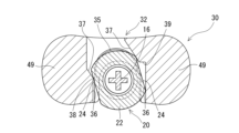
この実施例の注射器バレル用グリップ30は、フランジ22を収納するフランジ収納部32を備える。図2に示すように、フランジ収納部32は、グリップ30の側面に形成された側面開口33と、側面開口33よりグリップ30の内部方向に延びるフランジ挿入部34と、フランジ挿入部34と連通し、グリップ30の内部に延び、フランジ挿入部34にフランジ22が収納された状態にて、バレル20を所定角度回転させることにより、フランジ22が進入し、進入したフランジ22とグリップ30との相対的な回動を規制するフランジ回動規制部35とを備える。フランジ挿入部34は、一対のフランジストレート部24,24(幅w)より若干幅W1が広い第1の一対のグリップストレート部36,36を備え、フランジ回動規制部35は、一対のフランジストレート部24,24(幅w)より若干幅W2が広く、かつ、第1の一対のグリップストレート部36,36に対して、斜めとなっている第2の一対のグリップストレート部37,37を備える。
The structure of a
The
本実施例では、図2、図10、図12ないし図14に示すように、フランジ挿入部34のフランジ回動規制部35側の端部に、バレル20を回転させてフランジ回動規制部35に進入させる際に、フランジ22(フランジストレート部24)と当接する凸部38が形成されている。図10に示されるように、グリップ30では、フランジ挿入部34の左側(図10中)の第1のグリップストレート部36のフランジ回動規制部35側の端部(左側の第1のグリップストレート部36と左側の第2のグリップストレート部37との連結部)において、凸部38が形成されている。また、図10に示されるように、右側(図10中)の第1のグリップストレート部36と右側の第2のグリップストレート部37との間には、第1のグリップストレート部36と直角に連続し、第1のグリップストレート部36と第2のグリップストレート部37とを接続する段部39が形成されている。In this embodiment, as shown in Figs. 2, 10, 12 to 14, a
図2および図14に示されるように、グリップ30は、フランジ22が、フランジ回動規制部35に収納された状態において、一対のフランジストレート部24,24の前方側は、第2の一対のグリップストレート部37,37内(第2の一対のグリップストレート部37,37の間)に位置し、一対のフランジストレート部24,24の後方側は、第1の一対のグリップストレート部36,36内(第1の一対のグリップストレート部36,36の間)に位置するようにされている。As shown in Figures 2 and 14, when the
さらに、この実施例では、一対のフランジストレート部24,24の一方の後端部(フランジ22のグリップ30内への進入方向後方側の端部)が、第1の一対のグリップストレート部36,36の一方と当接もしくは近接するようになっている。すなわち、図2および図14に示されるように、図2および図14中で、右側のフランジストレート部24の後端部が、右側の第1のグリップストレート部36と当接もしくは近接するようになっている。これにより、フランジ回動規制部35に収納されたフランジ22が、第2の一対のグリップストレート部37,37に沿って動く(がたつく)ことや、フランジ回動規制部35から離脱することが阻止される。Furthermore, in this embodiment, the rear end of one of the pair of flange
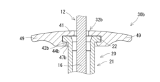
図3および図4に示されるように、グリップ30は、バレル20のフランジ22が、グリップ30のフランジ回動規制部35に収納された状態において、グリップ30の下部内周面は、バレル20と接触せず、グリップ30の下部内周面とバレル20間に滅菌用気体を流入させるための空隙40を備えている。As shown in Figures 3 and 4, when the
より具体的には、図7に示されるように、フランジ収納部32は、フランジ22の基端側面を覆う上板部41と、フランジ22の先端側面を覆う下板部42とを備える。図5および図7に示されるように、フランジ収納部32の上板部41と下板部42との間の距離Tは、フランジ22の厚さ寸法tよりも大きくされている。これにより、上板部41とフランジ22の基端側面との間、および下板部42とフランジ22の先端側面との間の少なくとも一方において、滅菌用気体を流入させるための空隙が形成されるようになっている。7, the
図8に示されるように、フランジ収納部32の上板部41には、上部スリット(開口)43が形成されている。上部スリット43は、フランジ収納部32の側面開口33、フランジ挿入部34およびフランジ回動規制部35と連通し、プランジャ12の軸部16が進入可能に形成されている。上部スリット43の内縁部の一部は、内方に突出し、プランジャ12のストッパ部17と当接するストッパ当接部31とされている。
これにより、上部スリット43は、プランジャ12の軸部16の通過を許容する一方、ストッパ当接部31において、プランジャ12のストッパ部17と当接する。そのため、図6に示されるように、バレル20に収納されたプランジャ12は、ストッパ部17においてグリップ30のストッパ当接部31と当接することで、バレル20からの離脱が規制される。
8, an upper slit (opening) 43 is formed in the
As a result, the
図9および図10に示されるように、フランジ収納部32の下板部42には、下部スリット(開口)44が形成されている。下部スリット44は、フランジ収納部32の側面開口33、フランジ挿入部34およびフランジ回動規制部35と連通しており、バレル20の筒状本体21が進入可能に形成されている。より具体的には、下板部42(下部スリット44)は、下部スリット44内に進入するバレル20(筒状本体21)部分の外形(外径)よりも大きく(広く)、かつ、一対のフランジストレート部24,24の幅wよりも狭い幅W3とされ、それぞれ、第1の一対のグリップストレート部36,36と略平行とされている一対の下部ストレート部45,45を備えるバレル挿入部46を備えている。9 and 10, a lower slit (opening) 44 is formed in the
図11に示すように、下板部42(下部スリット44)は、バレル挿入部46と連通し、フランジ22が、フランジ回動規制部35に収納された状態において、バレル20(筒状本体21)を部分的に取り囲む(バレル20を収納する)バレル収納部47を備える。バレル収納部47は、その内形(内径、図11に示される半径R)が、そこに収納されるバレル20(筒状本体21)の外形(外径、図3に示される半径r)よりも大きくされている。これにより、図3に示されるように、フランジ22が、グリップ30のフランジ回動規制部35に収納された状態において、バレル収納部47の内周面は、バレル20と接触せず、バレル収納部47の内周面とバレル20間に滅菌用気体を流入させるための空隙40が形成されるようになっている。すなわち、グリップ30においては、フランジ収納部32の下板部42(下部スリット44のバレル収納部47)の内周面において、グリップ30の下部内周面の少なくとも一部が構成されている。
なお、図7および図10に示すように、下板部42の上部内縁部には、凹部48が形成されている。これにより、下板部42と対向するフランジ22の先端側面のより広い範囲に滅菌用気体を接触させることができる。
As shown in Fig. 11, the lower plate portion 42 (lower slit 44) is connected to the
7 and 10, a
グリップ30のフランジ収納部32には、グリップ30の基端側部分を構成し、外方(バレル20の軸方向に直交する方向)に突出するように、一対の指掛け部49,49が形成されている。一対の指掛け部49,49は、バレル20の軸方向に直交する方向へ互いに逆向きに突出している。一対の指掛け部49,49は、バレル20のフランジ22よりも外方に延出している。一対の指掛け部49,49は、シリンジ1の操作時に、作業者が指を掛けるために利用できる。A pair of finger hooks 49, 49 are formed in the
本実施例のグリップ30は、図5および図7に示すように、フランジ収納部32より、軸方向先端側に延びる側壁部50を備える。側壁部50は、基端においてフランジ収納部32の下板部42の下部スリット44の内縁部と一体と(連結)されている。側壁部50は、図7に示されるように、基端側(フランジ収納部32側)に向かって外形が大きくなり、フランジ収納部32の指掛け部49,49に滑らかに連結されている。これにより、側壁部50は、シリンジ1の操作性の向上に寄与する。
As shown in Figures 5 and 7, the
側壁部50は、内周面が、軸方向全長に亘って、下部スリット44の内周面を軸方向に延長したものとされており、全体として、断面略U字形の半筒形状となっている。側壁部50には、軸方向に全長に亘って延びる挿入用(筒状本体21の基端部の挿入用)開口(挿入用スリット)51が形成されている。側壁部50の内周面は、バレル20のフランジ22が、グリップ30のフランジ回動規制部35に収納された状態において、バレル20と接触せず、バレル20との間に滅菌用気体を流入させるための空隙(空隙40、および空隙40と連続する空隙)を形成する。言い換えれば、側壁部50は、フランジ22と隣接する筒状本体21の基端部を部分的に覆うとともに、内周面の少なくとも一部が、バレル20との間に滅菌用気体を流入させるための空隙を形成するグリップ30の下部内周面を構成する。The
グリップ30の構成材料としては、ポリエチレン、ポリプロピレンなどのポリオレフィン、ポリスチレン、ポリアミド、ポリカーボネート、ポリ塩化ビニル、ポリ-(4-メチルペンテン-1)、アクリル樹脂、アクリロニトリル-ブタジエン-スチレン共重合体、ポリエチレンテレフタレート等のポリエステル、環状ポリオレフィンポリマー、環状オレフィンコポリマー等の硬質もしくは半硬質樹脂を用いることが好ましい。As a constituent material for the
なお、グリップ30の構成材料は、バレル20の構成材料よりも熱膨張率(線熱膨張率)が大きいものを用いてもよい。これにより、後述する表面滅菌(ガス滅菌)工程において、シリンジ1が加熱されたとき、バレル20(筒状本体21)の外面(外径)よりもグリップ30の内面(内径)が大きく膨張し、グリップ30の内面と筒状本体21の外面との間に隙間が形成もしくは拡大し、その隙間に滅菌用気体が進入することで、シリンジ1の滅菌性が向上し得る。The material of the
このようなシリンジ1の製造方法(製造工程)について、説明する。
まず、バレル20のノズル部23にシールキャップ13を装着した状態でバレル20を滅菌処理する。なお、このとき採用する滅菌方法は、特に限定されず、例えば、オートクレーブを用いたオートクレーブ滅菌法(高温蒸気滅菌法)、過酸化水素やEOGのような滅菌用気体を用いた表面滅菌法(ガス滅菌法)、γ線や電子放射線のような放射線照射による放射線滅菌法等を用いることができる。ここでは、一例として、オートクレーブ滅菌を実施する。
A method (manufacturing process) for manufacturing such a
First, the
次いで、無菌環境下で、滅菌されたバレル20内に、予め滅菌処理(例えば、ろ過滅菌等)が施された薬剤60を無菌充填する。本実施例では、比較的熱に弱い眼科用途の薬剤60が充填される。薬剤60を充填した後、ガスケット11をバレル20内に挿入する。ガスケット11の挿入(打栓)は、減圧状態で行うことができる。Next, in a sterile environment, the sterilized
次いで、バレル20内にプランジャ12の先端側部分を収納して、バレル20にグリップ30を装着する。なお、この作業は無菌環境下ではない場所で行うこともできる。Next, the tip portion of the
バレル20にグリップ30を装着する工程について、図12ないし図14を用いて、詳細に説明する。
先ず、図12に示されるように、バレル20の一対のフランジストレート部24,24と、グリップ30の第1の一対のグリップストレート部36,36とを略平行にした状態で、バレル20のフランジ22を、側面開口33からグリップ30の内部に挿入し、フランジ22をフランジ挿入部34に収納する。
The process of attaching the
First, as shown in FIG. 12 , with the pair of flange
次いで、フランジ挿入部34にフランジ22が収納された状態にて、バレル20を回転方向(ここでは、反時計回り)に付勢し、回転させる。バレル20が回転する過程で、図13に示されるように、一対のフランジストレート部24,24の一方(ここでは、図13中で左側のフランジストレート部24)が、凸部38に当接するとともに、他方(ここでは、図13中で右側のフランジストレート部24)の後端部またはその近傍部分が、図13中で右側の第1のグリップストレート部36に当接する状態[グリップ30(フランジ収納部32)とバレル20(フランジ22)とが一時的に係合した状態(第1の係合状態)]となる。Next, with the
グリップ30とバレル20とが係合した状態から、さらに、バレル20を回転方向に付勢すると、グリップ30(フランジ収納部32および側壁部50)には、上部スリット43や下部スリット44、挿入用スリット51が形成されているため、グリップ30のフランジ収納部32が弾性変形して押し広げられる。これにより、バレル20の回転が許容され、バレル20(フランジ22)とグリップ30(フランジ収納部32)との係合状態が解除されるとともに、フランジ22がフランジ回動規制部35へ進入することとなる。すなわち、グリップ30は、フランジ挿入部34にフランジ22が収納された状態にて、バレル20を所定角度回転させることにより、フランジ22をフランジ回動規制部35に進入させる際に、バレル20と一時的に係合するようにされている。When the
図14に示されるように、フランジ22がフランジ回動規制部35に収納される(グリップ30がバレル20に装着される)と、弾性復元力によってグリップ30は元の状態に戻る。フランジ22をフランジ回動規制部35に進入させることにより、バレル20へのグリップ30の装着が完了する。フランジ22がフランジ回動規制部35に収納された状態において、一対のフランジストレート部24,24が、それぞれ、第2の一対のグリップストレート部37,37と対向することにより、バレル20とグリップ30との相対的な回動が規制される。14, when the
なお、図示はしないが、グリップ30が装着された状態において、バレル20を、フランジ22をフランジ回動規制部35へ進入させたときと反対の回転方向(ここでは、時計回り)に付勢した場合、一対のフランジストレート部24,24の一方(ここでは、図14中で左側のフランジストレート部24)が、凸部38に当接するとともに、他方(ここでは、図14中で右側のフランジストレート部24)の前端部またはその近傍部分が、図14中で右側の第2のグリップストレート部37に当接する状態[グリップ30(フランジ収納部32)とバレル20(フランジ22)とが一時的に係合した状態(第2の係合状態)]となる。そのため、バレル20に装着されたグリップ30が意図せずに脱落することを阻止できる。言い換えれば、グリップ30は、フランジ挿入部34にフランジ22が収納された状態にて、バレル20を所定角度回転させることにより、フランジ22をフランジ回動規制部35に進入させる際に、バレル20と一時的に係合する(第1の係合状態が存在する)ようにされているため、一旦フランジ回動規制部35に収納されたフランジ22において第2の係合状態が生じることとなり、装着後のバレル20からの離脱を防止できる。Although not shown, when the
次いで、バレル20にグリップ30が装着された状態のシリンジ1を滅菌処理する。本実施例では、バレル20内に収納されている薬剤60が比較的熱に弱い眼科用途の薬剤であるため、滅菌用気体(ここでは、NO2(二酸化窒素))を用いた表面滅菌(NO2滅菌)を実施する。
Next, the
以上のようにして、無菌的にシリンジ1を製造することができる。
本実施例のグリップ30(フランジ収納部32)は、フランジ挿入部34に設けられた第1の一対のグリップストレート部36,36に対して、斜めとなっている第2の一対のグリップストレート部37,37を備えるフランジ回動規制部35を備え、フランジ22が、フランジ回動規制部35に収納された状態において、一対のフランジストレート部24,24の一部が、第2の一対のグリップストレート部37,37内に位置するようにされている。そのため、グリップ30が注射器用バレル20に装着された状態で、フランジ22(バレル20)とグリップ30との相対的な回動が規制されるため、操作性が良好である。
In this manner, the
The grip 30 (flange housing portion 32) of this embodiment includes a flange
さらに、本実施例のグリップ30は、バレル20のフランジ22が、グリップ30のフランジ回動規制部35に収納された状態において、グリップ30の下部内周面(下板部42の下部スリット44の内周面および/または側壁部50の内周面)が、バレル20と接触せず、グリップ30の下部内周面とバレル20間に滅菌用気体を流入させるための空隙40を備えている。そのため、グリップ30およびバレル20の表面のより広い範囲に滅菌用気体を接触させることができ、注射器バレル用グリップ30およびそのようなグリップ30を装着した注射器用バレル20の滅菌がより確実なものとなる。Furthermore, in the
なお、本実施例では、バレル20の筒状本体21は、外形および内形の断面が略真円状の円筒形状のものであったが、これに限られず、断面が楕円状や多角形状等の各種の筒形状のものや、外形と内形とで断面形状が異なるもの等を、適宜に用いることができ、グリップ30(フランジ収納部32)の形状もそれに応じて適宜に変更することができる。In this embodiment, the
また、図15に示されるグリップ30aのように、側壁部(50)を設けなくてもよい。グリップ30aにおいては、フランジ収納部32aの下板部42aが、グリップ30aの最先端部(最下部)を構成する。これにより、グリップ30aをより小型化および軽量化することができる。
Also, as in the
図16に示されるグリップ30bは、上述したグリップ30a(下板部42a)に対して、フランジ収納部32bの下板部42bが肉厚にされている。これにより、グリップ30bの強度を高めることができる。グリップ30bにおいては、図16に示されるように、下板部42b(下部スリット44bのバレル収納部47b)の内周面(内形)が、下方に向かって拡がっている。これにより、下板部42bを厚くすることによりグリップ30bの強度を高めつつ、グリップ30bとバレル20との間への滅菌用気体の流入がより促進され、滅菌がより確実なものとなる。
In the
また、図17に示されるグリップ30cのように、フランジ収納部32cにおける、図17中で、右側の第1のグリップストレート部36cと、右側の第2のグリップストレート部37cとを、段部(39)を設けずに、そのまま連結してもよい。
また、図18に示されるグリップ30dのように、フランジ収納部32dにおける、図18中で、右側の第1のグリップストレート部36dと、右側の第2のグリップストレート部37dとを、ゆるやかな角度で連結する傾斜段部39dを設けてもよい。
Also, as in the
Furthermore, as in the
また、図示はしないが、フランジ収納部32において形成される凸部38についても、例示のものに限られない。例えば、第1のグリップストレート部36から、フランジ収納部32の内方に突出するように形成してもよく、形成部位についても、第1のグリップストレート部36のフランジ回動規制部35側の端部ではなく、第1のグリップストレート部36の中間部に形成してもよい。In addition, although not shown, the
本発明の注射器バレル用グリップは、以下のものである。
(1) 筒状本体と、前記筒状本体に設けられ、外方に突出し、かつ互いに平行に向かい合う一対のフランジストレート部が形成されているフランジとを備える注射器用バレルに装着される注射器バレル用グリップであって、
前記グリップは、前記フランジを収納するフランジ収納部を備え、
前記フランジ収納部は、前記グリップの側面に形成された側面開口と、前記側面開口より前記グリップの内部方向に延びるフランジ挿入部と、前記フランジ挿入部と連通し、前記グリップの内部に延び、前記フランジ挿入部に前記フランジが収納された状態にて、前記バレルを所定角度回転させることにより、前記フランジが進入し、進入した前記フランジと前記グリップとの相対的な回動を規制するフランジ回動規制部とを備え、
前記フランジ挿入部は、前記一対のフランジストレート部より若干幅が広い第1の一対のグリップストレート部を備え、前記フランジ回動規制部は、前記一対のフランジストレート部より若干幅が広く、かつ、前記第1の一対のグリップストレート部に対して、斜めとなっている第2の一対のグリップストレート部を備え、
前記フランジが、前記フランジ回動規制部に収納された状態において、前記一対のフランジストレート部の前方側は、前記第2の一対のグリップストレート部内に位置し、前記一対のフランジストレート部の後方側は、前記第1の一対のグリップストレート部内に位置し、
かつ、前記バレルの前記フランジが、前記グリップの前記フランジ回動規制部に収納された状態において、前記グリップの下部内周面は、前記バレルと接触せず、前記グリップの下部内周面と前記バレル間に滅菌用気体を流入させるための空隙を備えている注射器バレル用グリップ。
The syringe barrel grip of the present invention is as follows:
(1) A grip for a syringe barrel to be attached to a syringe barrel including a cylindrical body and a flange provided on the cylindrical body, the flange protruding outward and including a pair of flange straight portions facing each other in parallel, the grip comprising:
The grip includes a flange housing portion that houses the flange,
The flange housing portion includes a side opening formed on a side surface of the grip, a flange insertion portion extending from the side opening toward the inside of the grip, and a flange rotation restricting portion communicating with the flange insertion portion and extending into the inside of the grip, the flange entering the flange by rotating the barrel by a predetermined angle with the flange housed in the flange insertion portion, and restricting relative rotation between the entered flange and the grip,
the flange insertion portion includes a first pair of grip straight portions that are slightly wider than the pair of flange straight portions, and the flange rotation restricting portion includes a second pair of grip straight portions that are slightly wider than the pair of flange straight portions and are inclined with respect to the first pair of grip straight portions,
when the flange is housed in the flange rotation restricting portion, a front side of the pair of flange straight portions is located within the second pair of grip straight portions, and a rear side of the pair of flange straight portions is located within the first pair of grip straight portions,
and a grip for a syringe barrel, the grip having a lower inner circumferential surface that does not come into contact with the barrel when the flange of the barrel is housed in the flange rotation regulating portion of the grip, and a gap for allowing a sterilization gas to flow between the lower inner circumferential surface of the grip and the barrel.
本発明の注射器バレル用グリップは、筒状本体と、筒状本体に設けられ、外方に突出し、かつ互いに平行に向かい合う一対のフランジストレート部が形成されているフランジとを備える注射器用バレルに装着される注射器バレル用グリップである。本発明のグリップは、フランジを収納するフランジ収納部を備え、フランジ収納部は、グリップの側面に形成された側面開口と、側面開口よりグリップの内部方向に延びるフランジ挿入部と、フランジ挿入部と連通し、グリップの内部に延び、フランジ挿入部にフランジが収納された状態にて、バレルを所定角度回転させることにより、フランジが進入し、進入したフランジとグリップとの相対的な回動を規制するフランジ回動規制部とを備える。
さらに、本発明のグリップのフランジ挿入部は、一対のフランジストレート部より若干幅が広い第1の一対のグリップストレート部を備え、フランジ回動規制部は、一対のフランジストレート部より若干幅が広く、かつ、第1の一対のグリップストレート部に対して、斜めとなっている第2の一対のグリップストレート部を備え、フランジが、フランジ回動規制部に収納された状態において、一対のフランジストレート部の前方側は、第2の一対のグリップストレート部内に位置し、一対のフランジストレート部の後方側は、第1の一対のグリップストレート部内に位置する。
そのため、本発明の注射器バレル用グリップおよびバレル組立体ならびにシリンジにおいては、グリップが注射器用バレルに装着された状態で、フランジとグリップとの相対的な回動が規制されるため、操作性が良好である。
The grip for a syringe barrel of the present invention is a grip for a syringe barrel that is attached to a syringe barrel that includes a cylindrical main body and a flange that is provided on the cylindrical main body, protruding outward, and having a pair of flange straight portions that face each other in parallel. The grip of the present invention includes a flange housing portion that houses the flange, the flange housing portion including a side opening formed on a side surface of the grip, a flange insertion portion extending from the side opening toward the inside of the grip, and a flange rotation restricting portion that communicates with the flange insertion portion and extends into the grip, and that restricts relative rotation between the flange that has entered and the grip by rotating the barrel by a predetermined angle with the flange housed in the flange insertion portion.
Furthermore, the flange insertion portion of the grip of the present invention has a first pair of grip straight portions that are slightly wider than the pair of flange straight portions, and the flange rotation regulating portion has a second pair of grip straight portions that are slightly wider than the pair of flange straight portions and are oblique to the first pair of grip straight portions, and when the flange is stored in the flange rotation regulating portion, the front side of the pair of flange straight portions is located within the second pair of grip straight portions, and the rear side of the pair of flange straight portions is located within the first pair of grip straight portions.
Therefore, in the syringe barrel grip, barrel assembly, and syringe of the present invention, when the grip is attached to the syringe barrel, relative rotation between the flange and the grip is restricted, resulting in excellent operability.
さらに、本発明のグリップは、バレルのフランジが、グリップのフランジ回動規制部に収納された状態において、グリップの下部内周面は、バレルと接触せず、グリップの下部内周面とバレル間に滅菌用気体を流入させるための空隙を備えている。
そのため、本発明の注射器バレル用グリップおよびバレル組立体ならびにシリンジにおいては、グリップおよびバレルの表面のより広い範囲に滅菌用気体を接触させることができ、注射器バレル用グリップおよびそのようなグリップを装着した注射器用バレルの滅菌がより確実なものとなる。
Furthermore, in the grip of the present invention, when the flange of the barrel is stored in the flange rotation regulating portion of the grip, the lower inner surface of the grip does not come into contact with the barrel, and a gap is provided between the lower inner surface of the grip and the barrel to allow sterilization gas to flow therethrough.
Therefore, in the syringe barrel grip and barrel assembly, and syringe of the present invention, the sterilizing gas can be brought into contact with a wider area of the surface of the grip and the barrel, making sterilization of the syringe barrel grip and the syringe barrel to which such a grip is attached more reliable.
また、上記の実施態様は、以下のものであってもよい。
(2) 前記グリップは、前記フランジと隣接する前記筒状本体の基端部を部分的に覆う側壁部を備え、前記側壁部の内周面の少なくとも一部が前記下部内周面とされている上記(1)に記載の注射器バレル用グリップ。
(3) 前記グリップは、前記フランジ挿入部に前記フランジが収納された状態にて、前記バレルを所定角度回転させることにより、前記フランジを前記フランジ回動規制部に進入させる際に、前記バレルと一時的に係合する上記(1)または(2)に記載の注射器バレル用グリップ。
(4) 前記フランジ収納部は、前記フランジの基端側面を覆う上板部と、前記フランジの先端側面を覆う下板部とを備え、前記上板部と前記下板部との間の距離は、前記フランジの厚さ寸法よりも大きくされており、前記上板部と前記フランジの基端側面との間、および前記下板部と前記フランジの先端側面との間の少なくとも一方において、滅菌用気体を流入させるための空隙を備えている上記(1)ないし(3)のいずれかに記載の注射器バレル用グリップ。
The above embodiment may also be as follows.
(2) The grip for a syringe barrel according to (1) above, wherein the grip includes a side wall portion partially covering a base end portion of the cylindrical body adjacent to the flange, and at least a part of an inner circumferential surface of the side wall portion is defined as the lower inner circumferential surface.
(3) The grip for a syringe barrel according to (1) or (2) above, wherein the grip temporarily engages with the barrel when the flange is inserted into the flange rotation restricting portion by rotating the barrel through a predetermined angle with the flange housed in the flange insertion portion.
(4) A grip for a syringe barrel according to any one of (1) to (3) above, wherein the flange housing portion includes an upper plate portion covering a base end side surface of the flange and a lower plate portion covering a tip end side surface of the flange, the distance between the upper plate portion and the lower plate portion being greater than a thickness dimension of the flange, and a gap for allowing a sterilization gas to flow therein is provided at least either between the upper plate portion and the base end side surface of the flange or between the lower plate portion and the tip end side surface of the flange.
本発明のバレル組立体は、以下のものである。
(5) 筒状本体と、前記筒状本体の基端に設けられ、外方に突出し、かつ互いに平行に向かい合う一対のフランジストレート部が形成されているフランジとを備える注射器用バレルと、前記バレルに装着された上記(1)ないし(4)のいずれかに記載の注射器バレル用グリップとを備えるバレル組立体。
The barrel assembly of the present invention is as follows.
(5) A barrel assembly comprising: a syringe barrel including a cylindrical body; and a flange provided at a base end of the cylindrical body, protruding outward and having a pair of flange straight portions facing each other in parallel, and the syringe barrel grip according to any one of (1) to (4) above attached to the barrel.
本発明のバレル組立体は、筒状本体と、筒状本体に設けられ、外方に突出し、かつ互いに平行に向かい合う一対のフランジストレート部が形成されているフランジとを備える注射器用バレルに装着される注射器バレル用グリップを備える。当該グリップは、フランジを収納するフランジ収納部を備え、フランジ収納部は、グリップの側面に形成された側面開口と、側面開口よりグリップの内部方向に延びるフランジ挿入部と、フランジ挿入部と連通し、グリップの内部に延び、フランジ挿入部にフランジが収納された状態にて、バレルを所定角度回転させることにより、フランジが進入し、進入したフランジとグリップとの相対的な回動を規制するフランジ回動規制部とを備える。
さらに、当該グリップのフランジ挿入部は、一対のフランジストレート部より若干幅が広い第1の一対のグリップストレート部を備え、フランジ回動規制部は、一対のフランジストレート部より若干幅が広く、かつ、第1の一対のグリップストレート部に対して、斜めとなっている第2の一対のグリップストレート部を備え、フランジが、フランジ回動規制部に収納された状態において、一対のフランジストレート部の前方側は、第2の一対のグリップストレート部内に位置し、一対のフランジストレート部の後方側は、第1の一対のグリップストレート部内に位置する。
そのため、本発明のバレル組立体においては、グリップが注射器用バレルに装着された状態で、フランジとグリップとの相対的な回動が規制されるため、操作性が良好である。
The barrel assembly of the present invention comprises a syringe barrel grip attached to a syringe barrel comprising a cylindrical main body and a flange provided on the cylindrical main body, protruding outward and having a pair of flange straight portions formed parallel to each other. The grip comprises a flange housing portion for housing the flange, the flange housing portion comprising a side opening formed on a side surface of the grip, a flange insertion portion extending from the side opening toward the inside of the grip, and a flange rotation restricting portion communicating with the flange insertion portion and extending into the grip, the flange entering the flange by rotating the barrel by a predetermined angle with the flange housed in the flange insertion portion, and restricting relative rotation between the grip and the flange that has entered.
Furthermore, the flange insertion portion of the grip has a first pair of grip straight portions that are slightly wider than the pair of flange straight portions, and the flange rotation regulating portion has a second pair of grip straight portions that are slightly wider than the pair of flange straight portions and are oblique to the first pair of grip straight portions, and when the flange is stored in the flange rotation regulating portion, the front side of the pair of flange straight portions is located within the second pair of grip straight portions, and the rear side of the pair of flange straight portions is located within the first pair of grip straight portions.
Therefore, in the barrel assembly of the present invention, with the grip attached to the syringe barrel, relative rotation between the flange and the grip is restricted, resulting in good operability.
さらに、本発明のバレル組立体は、バレルのフランジが、グリップのフランジ回動規制部に収納された状態において、グリップの下部内周面は、バレルと接触せず、グリップの下部内周面とバレル間に滅菌用気体を流入させるための空隙を備えている。
そのため、本発明のバレル組立体においては、グリップおよびバレルの表面のより広い範囲に滅菌用気体を接触させることができ、注射器バレル用グリップおよびそのようなグリップを装着した注射器用バレルの滅菌がより確実なものとなる。
Furthermore, in the barrel assembly of the present invention, when the flange of the barrel is stored in the flange rotation regulating portion of the grip, the lower inner circumferential surface of the grip does not come into contact with the barrel, and a gap is provided between the lower inner circumferential surface of the grip and the barrel to allow sterilizing gas to flow therethrough.
Therefore, in the barrel assembly of the present invention, the sterilizing gas can come into contact with a wider area of the surface of the grip and the barrel, making it possible to more reliably sterilize the syringe barrel grip and the syringe barrel to which such a grip is attached.
本発明のシリンジは、以下のものである。
(6) 上記(5)に記載のバレル組立体と、前記バレル内に摺動可能に収納されたガスケットと、前記ガスケット移動用のプランジャとを備えるシリンジ。
The syringe of the present invention is as follows.
(6) A syringe comprising the barrel assembly according to (5) above, a gasket slidably housed within the barrel, and a plunger for moving the gasket.
本発明のシリンジは、筒状本体と、筒状本体に設けられ、外方に突出し、かつ互いに平行に向かい合う一対のフランジストレート部が形成されているフランジとを備える注射器用バレルに装着される注射器バレル用グリップを備える。当該グリップは、フランジを収納するフランジ収納部を備え、フランジ収納部は、グリップの側面に形成された側面開口と、側面開口よりグリップの内部方向に延びるフランジ挿入部と、フランジ挿入部と連通し、グリップの内部に延び、フランジ挿入部にフランジが収納された状態にて、バレルを所定角度回転させることにより、フランジが進入し、進入したフランジとグリップとの相対的な回動を規制するフランジ回動規制部とを備える。
さらに、当該グリップのフランジ挿入部は、一対のフランジストレート部より若干幅が広い第1の一対のグリップストレート部を備え、フランジ回動規制部は、一対のフランジストレート部より若干幅が広く、かつ、第1の一対のグリップストレート部に対して、斜めとなっている第2の一対のグリップストレート部を備え、フランジが、フランジ回動規制部に収納された状態において、一対のフランジストレート部の前方側は、第2の一対のグリップストレート部内に位置し、一対のフランジストレート部の後方側は、第1の一対のグリップストレート部内に位置する。
そのため、本発明のシリンジにおいては、グリップが注射器用バレルに装着された状態で、フランジとグリップとの相対的な回動が規制されるため、操作性が良好である。
The syringe of the present invention comprises a grip for a syringe barrel to be attached to a syringe barrel comprising a cylindrical body and a flange provided on the cylindrical body, protruding outward and having a pair of flange straight portions formed parallel to each other. The grip comprises a flange housing portion for housing the flange, the flange housing portion comprising a side opening formed on a side surface of the grip, a flange insertion portion extending from the side opening toward the inside of the grip, and a flange rotation restricting portion communicating with the flange insertion portion and extending into the grip, the flange entering the flange by rotating the barrel by a predetermined angle with the flange housed in the flange insertion portion, and restricting relative rotation between the grip and the flange that has entered.
Furthermore, the flange insertion portion of the grip has a first pair of grip straight portions that are slightly wider than the pair of flange straight portions, and the flange rotation regulating portion has a second pair of grip straight portions that are slightly wider than the pair of flange straight portions and are oblique to the first pair of grip straight portions, and when the flange is stored in the flange rotation regulating portion, the front side of the pair of flange straight portions is located within the second pair of grip straight portions, and the rear side of the pair of flange straight portions is located within the first pair of grip straight portions.
Therefore, in the syringe of the present invention, relative rotation between the flange and the grip is restricted when the grip is attached to the syringe barrel, providing good operability.
さらに、本発明のシリンジは、バレルのフランジが、グリップのフランジ回動規制部に収納された状態において、グリップの下部内周面は、バレルと接触せず、グリップの下部内周面とバレル間に滅菌用気体を流入させるための空隙を備えている。
そのため、本発明のシリンジにおいては、グリップおよびバレルの表面のより広い範囲に滅菌用気体を接触させることができ、注射器バレル用グリップおよびそのようなグリップを装着した注射器用バレルの滅菌がより確実なものとなる。
Furthermore, in the syringe of the present invention, when the flange of the barrel is stored in the flange rotation regulating portion of the grip, the lower inner surface of the grip does not come into contact with the barrel, and a gap is provided between the lower inner surface of the grip and the barrel to allow sterilizing gas to flow therethrough.
Therefore, in the syringe of the present invention, the sterilizing gas can come into contact with a wider area of the surface of the grip and the barrel, making it possible to more reliably sterilize the syringe barrel grip and the syringe barrel to which such a grip is attached.
また、上記の実施態様は、以下のものであってもよい。
(7) 前記プランジャは、先端側部分が前記バレル内に収納されており、前記プランジャは、前記バレルに収納される部分に設けられ、前記グリップと当接し、前記プランジャの前記バレルからの離脱を規制するストッパ部を備えている上記(6)に記載のシリンジ。
(8) 前記プランジャは、前記ガスケットと連結されておらず、かつ、先端に前記ガスケットの基端部と当接するガスケット押圧部を備えている上記(6)または(7)に記載のシリンジ。
(9) 前記バレル内に薬剤が収納されている上記(6)ないし(8)のいずれに記載のシリンジ。
The above embodiment may also be as follows.
(7) The syringe according to (6) above, wherein a tip portion of the plunger is housed within the barrel, and the plunger is provided at a portion housed in the barrel and includes a stopper portion that abuts against the grip and prevents the plunger from coming out of the barrel.
(8) The syringe according to (6) or (7) above, wherein the plunger is not connected to the gasket and has a gasket pressing portion at a tip end thereof that abuts against a base end portion of the gasket.
(9) A syringe according to any one of (6) to (8) above, wherein a medicine is stored in the barrel.
Claims (9)
前記グリップは、前記フランジを収納するフランジ収納部を備え、
前記フランジ収納部は、前記グリップの側面に形成された側面開口と、前記側面開口より前記グリップの内部方向に延びるフランジ挿入部と、前記フランジ挿入部と連通し、前記グリップの内部に延び、前記フランジ挿入部に前記フランジが収納された状態にて、前記バレルを所定角度回転させることにより、前記フランジが進入し、進入した前記フランジと前記グリップとの相対的な回動を規制するフランジ回動規制部とを備え、
前記フランジ挿入部は、前記一対のフランジストレート部より若干幅が広い第1の一対のグリップストレート部を備え、前記フランジ回動規制部は、前記一対のフランジストレート部より若干幅が広く、かつ、前記第1の一対のグリップストレート部に対して、斜めとなっている第2の一対のグリップストレート部を備え、
前記フランジが、前記フランジ回動規制部に収納された状態において、前記一対のフランジストレート部の前方側は、前記第2の一対のグリップストレート部内に位置し、前記一対のフランジストレート部の後方側は、前記第1の一対のグリップストレート部内に位置し、
かつ、前記バレルの前記フランジが、前記グリップの前記フランジ回動規制部に収納された状態において、前記グリップの下部内周面は、前記バレルと接触せず、前記グリップの下部内周面と前記バレル間に滅菌用気体を流入させるための空隙を備えていることを特徴とする注射器バレル用グリップ。 A syringe barrel grip to be attached to a syringe barrel including a cylindrical body and a flange provided on the cylindrical body, the flange protruding outward and including a pair of flange straight portions facing each other in parallel, the grip comprising:
The grip includes a flange housing portion that houses the flange,
The flange housing portion includes a side opening formed on a side surface of the grip, a flange insertion portion extending from the side opening toward the inside of the grip, and a flange rotation restricting portion communicating with the flange insertion portion and extending into the inside of the grip, the flange entering the flange by rotating the barrel by a predetermined angle with the flange housed in the flange insertion portion, and restricting relative rotation between the entered flange and the grip,
the flange insertion portion includes a first pair of grip straight portions that are slightly wider than the pair of flange straight portions, and the flange rotation restricting portion includes a second pair of grip straight portions that are slightly wider than the pair of flange straight portions and are inclined with respect to the first pair of grip straight portions,
when the flange is housed in the flange rotation restricting portion, a front side of the pair of flange straight portions is located within the second pair of grip straight portions, and a rear side of the pair of flange straight portions is located within the first pair of grip straight portions,
and when the flange of the barrel is housed in the flange rotation restricting portion of the grip, a lower inner circumferential surface of the grip does not come into contact with the barrel, and a gap is provided between the lower inner circumferential surface of the grip and the barrel for allowing a sterilizing gas to flow therein.
Applications Claiming Priority (3)
| Application Number | Priority Date | Filing Date | Title |
|---|---|---|---|
| JP2020052233 | 2020-03-24 | ||
| JP2020052233 | 2020-03-24 | ||
| PCT/JP2021/003898 WO2021192637A1 (en) | 2020-03-24 | 2021-02-03 | Syringe-barrel grip, barrel assembly, and syringe |
Publications (2)
| Publication Number | Publication Date |
|---|---|
| JPWO2021192637A1 JPWO2021192637A1 (en) | 2021-09-30 |
| JP7488331B2 true JP7488331B2 (en) | 2024-05-21 |
Family
ID=77891383
Family Applications (1)
| Application Number | Title | Priority Date | Filing Date |
|---|---|---|---|
| JP2022509347A Active JP7488331B2 (en) | 2020-03-24 | 2021-02-03 | Grip and barrel assembly for syringe barrel, and syringe |
Country Status (5)
| Country | Link |
|---|---|
| US (1) | US12502484B2 (en) |
| EP (1) | EP4098298B1 (en) |
| JP (1) | JP7488331B2 (en) |
| CN (1) | CN114929311B (en) |
| WO (1) | WO2021192637A1 (en) |
Families Citing this family (1)
| Publication number | Priority date | Publication date | Assignee | Title |
|---|---|---|---|---|
| WO2024008948A1 (en) * | 2022-07-07 | 2024-01-11 | Terumo Europe Nv | Finger grip |
Citations (2)
| Publication number | Priority date | Publication date | Assignee | Title |
|---|---|---|---|---|
| JP2017527406A (en) | 2014-09-18 | 2017-09-21 | ヤンセン・バイオテック・インコーポレイテッドJanssen Biotech, Inc. | Therapeutic drug delivery device |
| JP2019510589A (en) | 2016-04-08 | 2019-04-18 | アラーガン、インコーポレイテッドAllergan,Incorporated | Suction and injection device |
Family Cites Families (10)
| Publication number | Priority date | Publication date | Assignee | Title |
|---|---|---|---|---|
| JP2004097277A (en) * | 2002-09-05 | 2004-04-02 | Arute:Kk | Auxiliary grip for container / syringe |
| JP2004313369A (en) * | 2003-04-15 | 2004-11-11 | Menicon Co Ltd | Cartridge injector, cartridge and ophthalmic injector set equipped with the injector |
| WO2013038887A1 (en) * | 2011-09-14 | 2013-03-21 | テルモ株式会社 | Liquid injection device |
| KR102288287B1 (en) | 2012-06-01 | 2021-08-11 | 노파르티스 아게 | Syringe |
| JOP20200175A1 (en) * | 2012-07-03 | 2017-06-16 | Novartis Ag | Syringe |
| JP2015080688A (en) * | 2013-10-24 | 2015-04-27 | 大成化工株式会社 | Fitting tool for syringe |
| KR102507581B1 (en) * | 2015-01-19 | 2023-03-08 | 가부시끼가이샤 제이엠에스 | Medical body fluid injector |
| CN107427639B (en) * | 2015-03-24 | 2020-10-02 | 泰尔茂株式会社 | Syringe Holders and Administration Assemblies |
| WO2017039786A1 (en) * | 2015-09-02 | 2017-03-09 | Amgen Inc. | Syringe assembly adapter for a syringe |
| EP3369447A4 (en) | 2015-10-30 | 2019-06-26 | Terumo Kabushiki Kaisha | Grip and syringe assembly |
-
2021
- 2021-02-03 WO PCT/JP2021/003898 patent/WO2021192637A1/en not_active Ceased
- 2021-02-03 CN CN202180008185.9A patent/CN114929311B/en active Active
- 2021-02-03 EP EP21776305.1A patent/EP4098298B1/en active Active
- 2021-02-03 JP JP2022509347A patent/JP7488331B2/en active Active
-
2022
- 2022-07-22 US US17/871,334 patent/US12502484B2/en active Active
Patent Citations (2)
| Publication number | Priority date | Publication date | Assignee | Title |
|---|---|---|---|---|
| JP2017527406A (en) | 2014-09-18 | 2017-09-21 | ヤンセン・バイオテック・インコーポレイテッドJanssen Biotech, Inc. | Therapeutic drug delivery device |
| JP2019510589A (en) | 2016-04-08 | 2019-04-18 | アラーガン、インコーポレイテッドAllergan,Incorporated | Suction and injection device |
Also Published As
| Publication number | Publication date |
|---|---|
| CN114929311A (en) | 2022-08-19 |
| US20220355038A1 (en) | 2022-11-10 |
| CN114929311B (en) | 2023-07-28 |
| WO2021192637A1 (en) | 2021-09-30 |
| JPWO2021192637A1 (en) | 2021-09-30 |
| US12502484B2 (en) | 2025-12-23 |
| EP4098298A4 (en) | 2023-07-19 |
| EP4098298B1 (en) | 2025-08-27 |
| EP4098298A1 (en) | 2022-12-07 |
Similar Documents
| Publication | Publication Date | Title |
|---|---|---|
| JP6700177B2 (en) | Tip cap assembly for closing injection system | |
| JP2025003722A (en) | Grip and barrel assembly for syringe barrel, and syringe | |
| US11033676B2 (en) | Drug delivery device and method for connecting a fluid flowpath | |
| US9511189B2 (en) | Insertion mechanism for a drug delivery pump | |
| JP5670242B2 (en) | Drug preparation tool | |
| ES2966643T3 (en) | Fill and Finish Cartridges for Sterile Fluid Path Assemblies and Drug Delivery Devices Incorporating Fill and Finish Cartridges | |
| EP1563863A1 (en) | Method of producing syringe, cap, and prefilled syringe | |
| JP6809982B2 (en) | Drug transfer assembly and adapter cap | |
| US10933192B2 (en) | Aseptic connections for drug delivery devices | |
| US20150196720A1 (en) | Outer cylinder for prefilled syringe, piercing tool for prefilled syringe, prefilled syringe, and packaging body for packaging outer cylinder for prefilled syringe | |
| JP2021511906A (en) | How to sterilize prefilled syringes and prefilled syringes | |
| JP7488331B2 (en) | Grip and barrel assembly for syringe barrel, and syringe | |
| JP2002078799A (en) | Liquid injection appliance | |
| JP2011212183A (en) | Prefilled syringe | |
| JP6255163B2 (en) | Drug preparation tool | |
| JPH0759865A (en) | Injection container | |
| JP2002177387A (en) | Syringe | |
| JP2000042106A (en) | Syringe for mixing medicinal solution | |
| HK1260733A1 (en) | Insertion mechanism for a drug delivery pump | |
| JP2003260112A (en) | Medicine blending method | |
| JP2001104481A (en) | Injector for prefilled syringe, and prefilled syringe | |
| JP2002078801A (en) | Liquid infusing instrument | |
| JPH0654907A (en) | Injection syringe |
Legal Events
| Date | Code | Title | Description |
|---|---|---|---|
| A621 | Written request for application examination |
Free format text: JAPANESE INTERMEDIATE CODE: A621 Effective date: 20230913 |
|
| TRDD | Decision of grant or rejection written | ||
| A01 | Written decision to grant a patent or to grant a registration (utility model) |
Free format text: JAPANESE INTERMEDIATE CODE: A01 Effective date: 20240507 |
|
| A61 | First payment of annual fees (during grant procedure) |
Free format text: JAPANESE INTERMEDIATE CODE: A61 Effective date: 20240509 |
|
| R150 | Certificate of patent or registration of utility model |
Ref document number: 7488331 Country of ref document: JP Free format text: JAPANESE INTERMEDIATE CODE: R150 |