WO2021192637A1 - Syringe-barrel grip, barrel assembly, and syringe - Google Patents
Syringe-barrel grip, barrel assembly, and syringe Download PDFInfo
- Publication number
- WO2021192637A1 WO2021192637A1 PCT/JP2021/003898 JP2021003898W WO2021192637A1 WO 2021192637 A1 WO2021192637 A1 WO 2021192637A1 JP 2021003898 W JP2021003898 W JP 2021003898W WO 2021192637 A1 WO2021192637 A1 WO 2021192637A1
- Authority
- WO
- WIPO (PCT)
- Prior art keywords
- flange
- grip
- barrel
- syringe
- pair
- Prior art date
Links
- 0 CCNCC(C)* Chemical compound CCNCC(C)* 0.000 description 1
Images


Classifications
-
- A—HUMAN NECESSITIES
- A61—MEDICAL OR VETERINARY SCIENCE; HYGIENE
- A61M—DEVICES FOR INTRODUCING MEDIA INTO, OR ONTO, THE BODY; DEVICES FOR TRANSDUCING BODY MEDIA OR FOR TAKING MEDIA FROM THE BODY; DEVICES FOR PRODUCING OR ENDING SLEEP OR STUPOR
- A61M5/00—Devices for bringing media into the body in a subcutaneous, intra-vascular or intramuscular way; Accessories therefor, e.g. filling or cleaning devices, arm-rests
- A61M5/178—Syringes
- A61M5/31—Details
- A61M5/3129—Syringe barrels
- A61M5/3137—Specially designed finger grip means, e.g. for easy manipulation of the syringe rod
- A61M2005/3139—Finger grips not integrally formed with the syringe barrel, e.g. using adapter with finger grips
-
- A—HUMAN NECESSITIES
- A61—MEDICAL OR VETERINARY SCIENCE; HYGIENE
- A61M—DEVICES FOR INTRODUCING MEDIA INTO, OR ONTO, THE BODY; DEVICES FOR TRANSDUCING BODY MEDIA OR FOR TAKING MEDIA FROM THE BODY; DEVICES FOR PRODUCING OR ENDING SLEEP OR STUPOR
- A61M5/00—Devices for bringing media into the body in a subcutaneous, intra-vascular or intramuscular way; Accessories therefor, e.g. filling or cleaning devices, arm-rests
- A61M5/001—Apparatus specially adapted for cleaning or sterilising syringes or needles
Definitions
- the present invention relates to a syringe barrel grip mounted on a syringe barrel, a barrel assembly having a syringe barrel grip, and a syringe.
- Some drug-filled syringes use plungers that are not attached to gaskets to prevent medical malpractice.
- a clip backstop for preventing the plunger from moving to the proximal end side and falling out of the barrel is attached (Patent Document 1).
- These clips are fitted to the outer peripheral surface of the barrel at the cylindrical fitting portion so as not to rattle or come off during operation of the syringe, and are firmly attached to the syringe.
- the present inventors examined the application of a surface sterilization method such as hydrogen peroxide sterilization, EOG sterilization, and NO 2 sterilization, which has a low heat load, to a prefilled syringe equipped with a grip.
- a surface sterilization method such as hydrogen peroxide sterilization, EOG sterilization, and NO 2 sterilization, which has a low heat load, to a prefilled syringe equipped with a grip.
- These surface sterilization methods are sterilization with a gas (sterilization gas), and in order to achieve higher sterilization, it is preferable that the sterilization gas comes into contact with a wider area on the surface of the prefilled syringe.
- the present invention relates to a syringe barrel grip that can be mounted on a syringe barrel, has good operability, and can achieve higher sterility, and a barrel assembly having such a syringe barrel grip. It provides a syringe.
- a syringe barrel grip attached to a syringe barrel provided with a cylindrical body and a flange provided on the tubular body and having a pair of flange straight portions that project outward and face each other in parallel.
- the grip includes a flange accommodating portion for accommodating the flange.
- the flange accommodating portion communicates with a side opening formed on the side surface of the grip, a flange insertion portion extending from the side opening toward the inside of the grip, and the flange insertion portion, and extends inside the grip.
- the flange insertion portion includes a first pair of grip straight portions that are slightly wider than the pair of flange straight portions, and the flange rotation restricting portion is slightly wider and slightly wider than the pair of flange straight portions.
- a second pair of grip straight portions that are oblique to the first pair of grip straight portions are provided.
- a barrel for a syringe provided with a tubular body, a barrel provided at the base end of the tubular body and formed with a pair of flange straight portions that project outward and face each other in parallel, and mounted on the barrel.
- a syringe comprising the barrel assembly, a gasket slidably housed in the barrel, and a plunger for moving the gasket.
- FIG. 1 is a front view showing an embodiment of the syringe of the present invention.
- FIG. 2 is a cross-sectional view taken along the line AA in FIG.
- FIG. 3 is a cross-sectional view taken along the line BB in FIG.
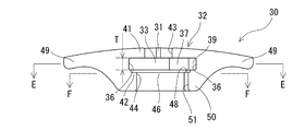
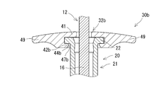
- FIG. 4 is an enlarged view of part D in FIG.
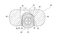
- FIG. 5 is a cross-sectional view taken along the line CC in FIG.
- FIG. 6 is an explanatory diagram for explaining the operation of the syringe shown in FIG.
- FIG. 7 is a front view of the syringe barrel grip used in the syringe of FIG.
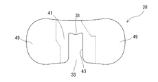
- FIG. 8 is a plan view of the syringe barrel grip used in the syringe of FIG.
- FIG. 1 is a front view showing an embodiment of the syringe of the present invention.
- FIG. 2 is a cross-sectional view taken along the line AA in FIG.
- FIG. 3 is a cross-sectional view taken along the
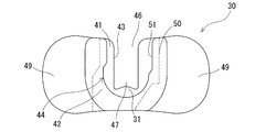
- FIG. 9 is a bottom view of the syringe barrel grip used in the syringe of FIG.
- FIG. 10 is a cross-sectional view taken along the line EE in FIG.
- FIG. 11 is a cross-sectional view taken along the line FF in FIG.
- FIG. 12 is a cross-sectional explanatory view corresponding to FIG. 10 for explaining the process of manufacturing the syringe of FIG.
- FIG. 13 is a cross-sectional explanatory view corresponding to FIG. 10 for explaining the process of manufacturing the syringe of FIG.
- FIG. 14 is a cross-sectional explanatory view corresponding to FIG. 10 for explaining the process of manufacturing the syringe of FIG.
- FIG. 15 is a partial cross-sectional explanatory view corresponding to FIG.
- FIG. 16 is a partial cross-sectional explanatory view corresponding to FIG. 5 for explaining a grip for a syringe barrel according to another embodiment of the present invention.
- FIG. 17 is a cross-sectional explanatory view corresponding to FIG. 10 for explaining a grip for a syringe barrel according to another embodiment of the present invention.
- FIG. 18 is a cross-sectional explanatory view corresponding to FIG. 10 for explaining a grip for a syringe barrel according to another embodiment of the present invention.
- the syringe barrel grips of the present invention will be described with reference to the embodiments shown in the drawings.
- the upper side in FIG. 1 (the side on which the flange 22 of the syringe barrel 20 is formed) is the base end side or the upper side
- the lower side in FIG. 1 (the nozzle portion 23 of the syringe barrel 20) is The provided side) will be the tip side or the lower side
- the vertical direction in FIG. 1 will be described as the axial direction (the axial direction of the barrel 20 for the syringe and the tubular body 21).
- the syringe 1 of the present invention includes a barrel 20 for a syringe (hereinafter, also simply referred to as a barrel 20) and a grip 30 for a syringe barrel mounted on the barrel 20 (hereinafter, simply a grip 30).
- a barrel assembly 2 including (also referred to as), a gasket 11 slidably housed in the barrel 20, and a plunger 12 for moving the gasket 11 are provided.
- the barrel 20 is provided on the cylindrical main body 21 and the tubular main body 21, and is a pair of flange straight portions 24, 24 (width w) that project outward (direction orthogonal to the axial direction of the barrel 20) and face each other in parallel. ) Is formed with a flange 22 (thickness t).
- the cylindrical main body 21 of the barrel 20 has a circular outer shape and an inner shape in a cross section formed by a plane orthogonal to the axial direction thereof as a whole.
- a tip opening (nozzle portion) 23 for discharging a drug is provided at the tip of the barrel 20.
- the barrel 20 includes a collar 25 that covers the base end side portion of the nozzle portion 23.
- a barrel-side screwed portion (female screwed portion) is formed on the inner surface of the collar 25.
- the nozzle portion 23 is sealed by a seal cap 13 to prevent leakage of the drug 60 stored in the barrel 20 and prevent the aseptically filled drug 60 from coming into contact with the outside air.
- Examples of the constituent material of the barrel 20 include polyolefins such as polyethylene and polypropylene, polystyrene, polyamide, polycarbonate, polyvinyl chloride, poly- (4-methylpentene-1), acrylic resin, and acrylonitrile-butadiene-styrene copolymer.
- Examples thereof include polyesters such as polyethylene terephthalate, cyclic polyolefin polymers, and various resins such as cyclic olefin copolymers.
- resins such as polypropylene, cyclic polyolefin polymers, and cyclic olefin copolymers are available because they are easy to mold and have heat resistance. preferable.
- Cyclic olefin polymers and cyclic olefin copolymers which have high transparency so that the chemical solution filled inside can be visually confirmed from the outside and have heat resistance to withstand high-pressure steam sterilization, are particularly preferable as the material for forming the barrel 20. ..
- the seal cap 13 includes a main body portion 18 having a base end side hollow portion for accommodating the nozzle portion 23 of the barrel 20, and a seal member 19 housed in the main body portion 18 and arranged at the tip end portion of the base end side hollow portion.
- a cap side screw portion male screw portion
- the barrel side screw portion female screw portion
- Examples of the material for forming the seal cap include polypropylene, polyethylene, polystyrene, polyamide, polycarbonate, polyvinyl chloride, poly- (4-methylpentene-1), acrylic resin, acrylonitrile-butadiene-styrene copolymer, polyethylene terephthalate and the like.
- Examples thereof include various resins such as polyester and cyclic polyolefin, and among them, resins such as polypropylene and cyclic polyolefin are preferable because they are easy to mold and have heat resistance.
- the material for forming the seal member 19 synthetic rubber such as natural rubber, isoprene rubber, butyl rubber, butadiene rubber, fluororubber, and silicone rubber, and elastic material such as thermoplastic elastomer such as olefin elastomer and styrene elastomer are preferable.
- the gasket 11 housed in the barrel 20 is made of elastic rubber or synthetic resin.
- the gasket 11 includes a substantially cylindrical main body portion extending with substantially the same outer diameter and a plurality of annular ribs provided on the outer surface of the main body portion, and the outer surface of the annular rib is liquid-tight on the inner surface of the barrel 20. It is in contact and can slide in a liquidtight state.
- Examples of the material for forming the gasket 11 include elastic rubber (for example, butyl rubber, latex rubber, silicone rubber, etc.), synthetic resin (for example, styrene elastomer such as SBS elastomer and SEBS elastomer, ethylene- ⁇ olefin copolymer elastomer, etc.). It is preferable to use an olefin-based elastomer or the like.
- the plunger 12 is made of a hard or semi-hard resin.
- the plunger 12 includes a small disk-shaped gasket pressing portion 14 provided at the tip, a disk-shaped pressing operation portion 15 provided at the base end, and a gasket pressing portion 14 having a cross-shaped cross section.
- a shaft portion 16 extending in the axial direction of the barrel 20 is provided between the pressing operation portions 15.
- the shaft portion 16 may be a columnar shaft.
- the columnar shaft may have a rod shape, a columnar shape, a polygonal columnar shape, a cylindrical shape, a polygonal tubular shape, or the like.
- the plunger 12 is not connected to the gasket 11, and can be brought into contact with the base end portion of the gasket 11 at the gasket pressing portion 14, and the gasket 11 is brought to the tip side by pressing after the contact. It is movable.
- the tip end side portion (the gasket pressing portion 14 and the tip end side portion of the shaft portion 16) is housed in the barrel 20 (cylindrical body 21).
- the plunger 12 is provided in a portion (shaft portion 16) housed in the barrel 20 and comes into contact with the grip 30 (stopper contact portion 31) described in detail later to regulate the departure of the plunger 12 from the barrel 20. 17 is provided. More specifically, the stopper portion 17 has an outer diameter (outer diameter) that is smaller than the inner shape (inner diameter) of the barrel 20 (cylindrical body 21) and larger than the outer diameter (maximum diameter portion) of the shaft portion 16 of the plunger 12. ) Is a disk shape.
- a hard or semi-hard resin such as high-density polyethylene, polypropylene, polystyrene, or polyethylene terephthalate.
- the drug (chemical solution) 60 is stored (filled) in the barrel 20 (in the space formed between the seal cap 13 and the gasket 11).
- the stored drug 60 is not particularly limited, but for example, vitamins, sugars, electrolytes, organic acids, minerals, fat emulsions, amino acids, proteins, organ preparations, etc., which are mainly nutritional supplements, are used. can give.
- general anesthetics as therapeutic agents, antipyretic analgesics and anti-inflammatory agents, central nervous system agents such as general sensitizers, local anesthetics, peripheral nervous system agents such as muscle relaxants, ophthalmic agents, etc.
- substances corresponding to molecular-targeted drugs such as antibodies can also be used as drugs.
- the dosage forms of these drugs are liquids even for drugs having solid dosage forms such as powders and granules in addition to liquids.
- an ophthalmic drug that can be administered by puncture can be used.
- Specific target diseases for which such ophthalmic agents are used include choroidal neovascularization, age-related macular degeneration (both exudative and atrophic), and macular edema (retinal vein) secondary to retinal vein occlusion (RVO).
- RVO retinal vein occlusion
- bRVO branch occlusion
- cRVO central retinal vein occlusion
- DME diabetic macular edema
- DME diabetic macular edema
- retinopathy and proliferation There is retinopathy and so on.
- drugs used include ranibizumab [trade name Lucentis®], bevacizumab [trade name Avastin®], and aflibercept, which are anti-VEGF antibodies used as therapeutic agents for age-related macular degeneration.
- examples thereof include Cept [trade name Eylea (registered trademark)] and convercept known as VEGF-TrapEye (aflibercept intravitreal injection).
- the syringe barrel grip 30 of this embodiment includes a flange accommodating portion 32 for accommodating the flange 22.
- the flange storage portion 32 communicates with the side opening 33 formed on the side surface of the grip 30, the flange insertion portion 34 extending inward from the side opening 33 in the grip 30, and the flange insertion portion 34.
- the flange insertion portion 34 includes a first pair of grip straight portions 36, 36 having a width W1 slightly wider than the pair of flange straight portions 24, 24 (width w), and the flange rotation restricting portion 35 includes a pair of flange straight portions.
- the width W2 is slightly wider than the portions 24 and 24 (width w), and the second pair of grip straight portions 37 and 37 are provided which are oblique to the first pair of grip straight portions 36 and 36. ..
- the flange 20 is rotated to the end of the flange insertion portion 34 on the flange rotation restricting portion 35 side to rotate the flange rotation restricting portion 35.
- a convex portion 38 that comes into contact with the flange 22 (flange straight portion 24) is formed.
- a convex portion 38 is formed at a connecting portion) between the portion 36 and the second grip straight portion 37 on the left side. Further, as shown in FIG.
- a stepped portion 39 is continuously formed to connect the first grip straight portion 36 and the second grip straight portion 37.
- the front side of the pair of flange straight portions 24, 24 is a second pair.
- the rear side of the pair of flange straight portions 24, 24 is the first pair of grip straight portions 36, 36. It is designed to be located inside (between the first pair of grip straight portions 36, 36).
- one rear end portion of the pair of flange straight portions 24, 24 (the end portion on the rear side in the approach direction of the flange 22 into the grip 30) is the first pair of grip straight portions 36, It is designed to be in contact with or close to one of 36. That is, as shown in FIGS. 2 and 14, the rear end portion of the flange straight portion 24 on the right side is in contact with or close to the first grip straight portion 36 on the right side in FIGS. 2 and 14. It has become. As a result, the flange 22 housed in the flange rotation restricting portion 35 is prevented from moving (rattling) along the second pair of grip straight portions 37, 37 and being separated from the flange rotation restricting portion 35. Will be done.
- the lower inner peripheral surface of the grip 30 is the barrel 20.
- a gap 40 is provided between the lower inner peripheral surface of the grip 30 and the barrel 20 so as to allow the sterilizing gas to flow in without contact.
- the flange accommodating portion 32 includes an upper plate portion 41 that covers the base end side surface of the flange 22, and a lower plate portion 42 that covers the front end side surface of the flange 22.
- the distance T between the upper plate portion 41 and the lower plate portion 42 of the flange accommodating portion 32 is made larger than the thickness dimension t of the flange 22.
- a gap for allowing the sterilizing gas to flow in is formed at least between the upper plate portion 41 and the base end side surface of the flange 22 and between the lower plate portion 42 and the tip end side surface of the flange 22. It has become like.
- an upper slit (opening) 43 is formed in the upper plate portion 41 of the flange accommodating portion 32.
- the upper slit 43 communicates with the side opening 33 of the flange accommodating portion 32, the flange inserting portion 34, and the flange rotation restricting portion 35, and is formed so that the shaft portion 16 of the plunger 12 can enter.
- a part of the inner edge portion of the upper slit 43 is a stopper contact portion 31 that protrudes inward and comes into contact with the stopper portion 17 of the plunger 12.
- the upper slit 43 allows the shaft portion 16 of the plunger 12 to pass through, while the stopper contact portion 31 comes into contact with the stopper portion 17 of the plunger 12. Therefore, as shown in FIG. 6, the plunger 12 housed in the barrel 20 comes into contact with the stopper contact portion 31 of the grip 30 at the stopper portion 17, so that the plunger 12 is restricted from being separated from the barrel 20.
- a lower slit (opening) 44 is formed in the lower plate portion 42 of the flange accommodating portion 32.
- the lower slit 44 communicates with the side opening 33 of the flange accommodating portion 32, the flange inserting portion 34, and the flange rotation restricting portion 35, and is formed so that the cylindrical main body 21 of the barrel 20 can enter.
- the lower plate portion 42 (lower slit 44) is larger (wider) than the outer diameter (outer diameter) of the barrel 20 (cylindrical main body 21) portion that enters the lower slit 44, and is paired.
- a barrel insertion portion having a width W3 narrower than the width w of the flange straight portions 24, 24 and having a pair of lower straight portions 45, 45 which are substantially parallel to the first pair of grip straight portions 36, 36, respectively. It is equipped with 46.
- the lower plate portion 42 (lower slit 44) communicates with the barrel insertion portion 46, and the barrel 20 (cylindrical main body 21) is in a state where the flange 22 is housed in the flange rotation restricting portion 35. ) Is provided with a barrel storage portion 47 that partially surrounds (stores the barrel 20).
- the inner shape (inner diameter, radius R shown in FIG. 11) of the barrel storage portion 47 is larger than the outer diameter (outer diameter, radius r shown in FIG. 3) of the barrel 20 (cylindrical body 21) stored therein. Has also been enlarged. As a result, as shown in FIG.
- a gap 40 for allowing the sterilizing gas to flow in is formed between the inner peripheral surface of the portion 47 and the barrel 20. That is, in the grip 30, at least a part of the lower inner peripheral surface of the grip 30 is formed on the inner peripheral surface of the lower plate portion 42 (barrel accommodating portion 47 of the lower slit 44) of the flange accommodating portion 32. As shown in FIGS. 7 and 10, a recess 48 is formed in the upper inner edge of the lower plate portion 42. As a result, the sterilizing gas can be brought into contact with a wider range on the front end side surface of the flange 22 facing the lower plate portion 42.
- the flange accommodating portion 32 of the grip 30 is formed with a pair of finger hook portions 49, 49 so as to form a base end side portion of the grip 30 and project outward (in a direction orthogonal to the axial direction of the barrel 20). ing.
- the pair of finger hooks 49, 49 project in opposite directions to each other in a direction orthogonal to the axial direction of the barrel 20.
- the pair of finger hooks 49, 49 extend outward from the flange 22 of the barrel 20.
- the pair of finger hooks 49, 49 can be used by the operator to hook the fingers when operating the syringe 1.
- the grip 30 of this embodiment includes a side wall portion 50 extending axially to the tip end side from the flange accommodating portion 32.
- the side wall portion 50 is integrally (connected) with the inner edge portion of the lower slit 44 of the lower plate portion 42 of the flange storage portion 32 at the base end.
- the side wall portion 50 has an outer shape that increases toward the base end side (flange storage portion 32 side), and is smoothly connected to the finger hook portions 49, 49 of the flange storage portion 32. As a result, the side wall portion 50 contributes to the improvement of the operability of the syringe 1.
- the inner peripheral surface of the side wall portion 50 is formed by extending the inner peripheral surface of the lower slit 44 in the axial direction over the entire length in the axial direction, and has a semi-cylindrical shape having a substantially U-shaped cross section as a whole. There is.
- the side wall portion 50 is formed with an insertion opening (insertion slit) 51 extending in the axial direction over the entire length (for inserting the base end portion of the tubular main body 21).
- the inner peripheral surface of the side wall portion 50 does not come into contact with the barrel 20 when the flange 22 of the barrel 20 is housed in the flange rotation restricting portion 35 of the grip 30, and a sterilizing gas flows into the inner peripheral surface of the side wall portion 50.
- a gap (a gap 40 and a gap continuous with the gap 40) is formed.
- the side wall portion 50 partially covers the base end portion of the cylindrical main body 21 adjacent to the flange 22, and at least a part of the inner peripheral surface allows the sterilizing gas to flow into the barrel 20. It constitutes the lower inner peripheral surface of the grip 30 that forms the gap between the two.
- the constituent materials of the grip 30 include polyolefins such as polyethylene and polypropylene, polystyrene, polyamide, polycarbonate, polyvinyl chloride, poly- (4-methylpentene-1), acrylic resin, acrylonitrile-butadiene-styrene copolymer, and polyethylene terephthalate. It is preferable to use a hard or semi-hard resin such as polyester, cyclic polyolefin polymer, cyclic olefin copolymer or the like.
- a material having a larger coefficient of thermal expansion (linear thermal expansion coefficient) than the constituent material of the barrel 20 may be used.
- the inner surface (inner diameter) of the grip 30 expands more than the outer surface (outer diameter) of the barrel 20 (cylindrical body 21).
- a gap is formed or expanded between the inner surface of the grip 30 and the outer surface of the tubular main body 21, and the sterilizing gas enters the gap, so that the sterilization of the syringe 1 can be improved.
- a method (manufacturing process) for manufacturing such a syringe 1 will be described.
- the barrel 20 is sterilized with the seal cap 13 attached to the nozzle portion 23 of the barrel 20.
- the sterilization method adopted at this time is not particularly limited, and for example, an autoclave sterilization method using an autoclave (high temperature steam sterilization method) and a surface sterilization method using a sterilization gas such as hydrogen peroxide or EOG (gas). Sterilization method), radiation sterilization method by irradiation such as ⁇ -ray or electron radiation can be used.
- autoclave sterilization is performed.
- the sterilized barrel 20 is aseptically filled with a drug 60 that has been sterilized in advance (for example, filtration sterilization).
- the drug 60 for ophthalmic use which is relatively heat-sensitive, is filled.
- the gasket 11 is inserted into the barrel 20. The gasket 11 can be inserted (plugged) in a reduced pressure state.
- the tip end side portion of the plunger 12 is stored in the barrel 20, and the grip 30 is attached to the barrel 20.
- This work can also be performed in a place other than an aseptic environment.
- the flange of the barrel 20 is in a state where the pair of flange straight portions 24, 24 of the barrel 20 and the first pair of grip straight portions 36, 36 of the grip 30 are substantially parallel to each other. 22 is inserted into the grip 30 through the side opening 33, and the flange 22 is housed in the flange insertion portion 34.
- the grip 30 (flange storage portion 32 and side wall portion 50) has an upper slit 43 and a lower slit 44 for insertion. Since the slit 51 is formed, the flange accommodating portion 32 of the grip 30 is elastically deformed and expanded. As a result, the rotation of the barrel 20 is allowed, the engagement state between the barrel 20 (flange 22) and the grip 30 (flange storage portion 32) is released, and the flange 22 enters the flange rotation restricting portion 35. It becomes.
- the grip 30 temporarily rotates with the barrel 20 when the flange 22 enters the flange rotation restricting portion 35 by rotating the barrel 20 by a predetermined angle while the flange 22 is housed in the flange inserting portion 34. Is designed to engage with each other.
- the barrel 20 was urged in the direction of rotation (clockwise in this case) opposite to that when the flange 22 was made to enter the flange rotation restricting portion 35 in the state where the grip 30 was attached.
- one of the pair of flange straight portions 24, 24 (here, the left flange straight portion 24 in FIG. 14) abuts on the convex portion 38, and the other (here, the right flange straight portion in FIG. 14) is in contact with the convex portion 38.
- a state in which the front end portion of the portion 24) or a portion in the vicinity thereof abuts on the second grip straight portion 37 on the right side in FIG. Engagement state (second engagement state)].
- the grip 30 is referred to as the barrel 20 when the flange 22 is brought into the flange rotation restricting portion 35 by rotating the barrel 20 by a predetermined angle in a state where the flange 22 is housed in the flange inserting portion 34. Since it is temporarily engaged (there is a first engaged state), a second engaged state occurs in the flange 22 once housed in the flange rotation restricting portion 35, and the flange 22 is mounted. It is possible to prevent the rear barrel 20 from being separated.
- the syringe 1 with the grip 30 attached to the barrel 20 is sterilized.
- the drug 60 stored in the barrel 20 is a drug for ophthalmology that is relatively sensitive to heat
- surface sterilization (NO) using a sterilizing gas here, NO 2 (nitrogen dioxide)
- NO 2 nitrogen dioxide
- the grip 30 (flange storage portion 32) of this embodiment is a second pair of grip straight portions that are oblique to the first pair of grip straight portions 36, 36 provided in the flange insertion portion 34.
- a part of the pair of flange straight portions 24, 24 is a second pair of grips in a state where the flange rotation restricting portion 35 including 37, 37 is provided and the flange 22 is housed in the flange rotation restricting portion 35. It is designed to be located within the straight portions 37, 37. Therefore, with the grip 30 mounted on the barrel 20 for a syringe, the relative rotation between the flange 22 (barrel 20) and the grip 30 is restricted, so that the operability is good.
- the lower inner peripheral surface of the grip 30 (the lower slit 44 of the lower plate portion 42).
- the inner peripheral surface and / or the inner peripheral surface of the side wall portion 50) does not come into contact with the barrel 20, and has a gap 40 for allowing sterilizing gas to flow between the lower inner peripheral surface of the grip 30 and the barrel 20. Therefore, the sterilizing gas can be brought into contact with a wider area on the surface of the grip 30 and the barrel 20, and the sterilization of the syringe barrel grip 30 and the syringe barrel 20 equipped with such a grip 30 is more reliable. Become.
- the tubular main body 21 of the barrel 20 has a cylindrical shape having a substantially perfect circular cross section in the outer shape and the inner shape, but the cross section is not limited to this, and the cross section is elliptical, polygonal, or the like.
- the cross section is elliptical, polygonal, or the like.
- Various cylindrical shapes and those having different cross-sectional shapes between the outer shape and the inner shape can be appropriately used, and the shape of the grip 30 (flange storage portion 32) can be appropriately changed accordingly. can.
- the lower plate portion 42a of the flange accommodating portion 32a constitutes the most advanced portion (lowermost portion) of the grip 30a. As a result, the grip 30a can be made smaller and lighter.
- the lower plate portion 42b of the flange accommodating portion 32b is thicker than the grip 30a (lower plate portion 42a) described above. Thereby, the strength of the grip 30b can be increased.
- the inner peripheral surface (inner shape) of the lower plate portion 42b (barrel storage portion 47b of the lower slit 44b) expands downward. As a result, the strength of the grip 30b is increased by thickening the lower plate portion 42b, and the inflow of the sterilizing gas between the grip 30b and the barrel 20 is further promoted, so that sterilization becomes more reliable.
- the first grip straight portion 36c on the right side and the second grip straight portion 37c on the right side of the flange accommodating portion 32c are formed into stepped portions ( You may connect it as it is without providing 39).
- the first grip straight portion 36d on the right side and the second grip straight portion 37d on the right side have a gentle angle in the flange accommodating portion 32d.
- An inclined step portion 39d connected with a may be provided.
- the convex portion 38 formed in the flange accommodating portion 32 is not limited to the example.
- it may be formed so as to protrude inward from the first grip straight portion 36 to the flange accommodating portion 32, and the forming portion may also be formed on the flange rotation restricting portion 35 side of the first grip straight portion 36. It may be formed in the middle portion of the first grip straight portion 36 instead of the end portion.
- the grip for the syringe barrel of the present invention is as follows. (1) For a syringe barrel mounted on a barrel for a syringe provided with a cylindrical main body and a flange provided on the tubular main body and having a pair of flange straight portions facing outward and facing parallel to each other. It ’s a grip,
- the grip includes a flange accommodating portion for accommodating the flange.
- the flange accommodating portion communicates with a side opening formed on the side surface of the grip, a flange insertion portion extending from the side opening toward the inside of the grip, and the flange insertion portion, and extends inside the grip.
- the flange insertion portion includes a first pair of grip straight portions that are slightly wider than the pair of flange straight portions, and the flange rotation restricting portion is slightly wider and slightly wider than the pair of flange straight portions.
- a second pair of grip straight portions that are oblique to the first pair of grip straight portions are provided.
- the grip for a syringe barrel of the present invention is attached to a barrel for a syringe provided with a cylindrical body and a flange provided on the tubular body and having a pair of flange straight portions that project outward and face each other in parallel. It is a grip for the syringe barrel to be used.
- the grip of the present invention includes a flange storage portion for accommodating a flange, and the flange storage portion includes a side opening formed on the side surface of the grip, a flange insertion portion extending inward of the grip from the side opening, and a flange insertion portion.
- the flange insertion portion of the grip of the present invention includes a first pair of grip straight portions that are slightly wider than the pair of flange straight portions, and the flange rotation restricting portion is slightly wider than the pair of flange straight portions.
- a second pair of grip straight portions that are oblique to the first pair of grip straight portions are provided, and the flange is housed in the flange rotation restricting portion, and the pair of flange straight portions is provided.
- the front side of the portion is located in the second pair of grip straight portions, and the rear side of the pair of flange straight portions is located in the first pair of grip straight portions. Therefore, in the syringe barrel grip, barrel assembly, and syringe of the present invention, the relative rotation between the flange and the grip is restricted while the grip is attached to the syringe barrel, so that operability is good. Is.
- the lower inner peripheral surface of the grip does not come into contact with the barrel, and the lower inner peripheral surface of the grip and the barrel Is provided with a gap for allowing the sterilizing gas to flow into the barrel. Therefore, in the syringe barrel grip and barrel assembly and syringe of the present invention, the sterilizing gas can be brought into contact with a wider area of the grip and barrel surface, and the syringe barrel grip and such a grip are attached. Sterilization of syringe barrels is more reliable.
- the grip includes a side wall portion that partially covers the base end portion of the tubular body adjacent to the flange, and at least a part of the inner peripheral surface of the side wall portion is the lower inner peripheral surface.
- the grip is provided with the barrel when the flange is brought into the flange rotation restricting portion by rotating the barrel by a predetermined angle while the flange is housed in the flange insertion portion.
- the grip for the syringe barrel according to (1) or (2) above which is temporarily engaged.
- the flange accommodating portion includes an upper plate portion that covers the base end side surface of the flange and a lower plate portion that covers the tip end side surface of the flange, and the distance between the upper plate portion and the lower plate portion. Is made larger than the thickness dimension of the flange, and is sterilized at least between the upper plate portion and the base end side surface of the flange and between the lower plate portion and the tip end side surface of the flange.
- the grip for a syringe barrel according to any one of (1) to (3) above, which has a gap for allowing a gas to flow in.
- the barrel assembly of the present invention is as follows. (5) A barrel for a syringe including a tubular main body, a barrel provided at the base end of the tubular main body, and a pair of flange straight portions that project outward and face each other in parallel, and the barrel. A barrel assembly comprising the syringe barrel grip according to any one of (1) to (4) above, which is mounted on the barrel assembly.
- the barrel assembly of the present invention is mounted on a barrel for a syringe comprising a cylindrical body and a flange provided on the tubular body and having a pair of flange straight portions that project outward and face each other in parallel. Equipped with a grip for the syringe barrel.
- the grip includes a flange storage portion for accommodating a flange, and the flange storage portion communicates with a side opening formed on the side surface of the grip, a flange insertion portion extending inward of the grip from the side opening, and a flange insertion portion.
- a second pair of grip straight portions that are slanted with respect to the first pair of grip straight portions, and in a state where the flange is housed in the flange rotation restricting portion, the pair of flange straight portions
- the front side is located in the second pair of grip straight portions
- the rear side of the pair of flange straight portions is located in the first pair of grip straight portions. Therefore, in the barrel assembly of the present invention, the relative rotation between the flange and the grip is restricted while the grip is attached to the barrel for a syringe, so that the operability is good.
- the lower inner peripheral surface of the grip does not come into contact with the barrel and is not in contact with the lower inner peripheral surface of the grip.
- a gap is provided between the barrels for allowing the sterilizing gas to flow in. Therefore, in the barrel assembly of the present invention, the sterilizing gas can be brought into contact with a wider area of the grip and the surface of the barrel, and the sterilization of the syringe barrel grip and the syringe barrel equipped with such a grip is more effective. It will be certain.
- the syringe of the present invention is as follows. (6) A syringe comprising the barrel assembly according to (5) above, a gasket slidably housed in the barrel, and a plunger for moving the gasket.
- the syringe of the present invention is a syringe mounted on a syringe barrel provided with a cylindrical body and a flange provided on the tubular body and having a pair of flange straight portions that project outward and face each other in parallel. Equipped with a grip for the barrel.
- the grip includes a flange storage portion for accommodating a flange, and the flange storage portion communicates with a side opening formed on the side surface of the grip, a flange insertion portion extending inward of the grip from the side opening, and a flange insertion portion.
- a second pair of grip straight portions that are slanted with respect to the first pair of grip straight portions, and in a state where the flange is housed in the flange rotation restricting portion, the pair of flange straight portions
- the front side is located in the second pair of grip straight portions
- the rear side of the pair of flange straight portions is located in the first pair of grip straight portions. Therefore, in the syringe of the present invention, the relative rotation between the flange and the grip is restricted while the grip is attached to the barrel for the syringe, so that the operability is good.
- the sterilizing gas can be brought into contact with a wider area of the grip and the surface of the barrel, and the sterilization of the syringe barrel grip and the syringe barrel equipped with such a grip is more reliable. It becomes a thing.
- the above-mentioned embodiment may be as follows. (7)
- the tip end side portion of the plunger is housed in the barrel, and the plunger is provided in the portion housed in the barrel and comes into contact with the grip to release the plunger from the barrel.
- the syringe according to (6) above which includes a stopper portion for regulating.
- (8) The syringe according to (6) or (7) above, wherein the plunger is not connected to the gasket and has a gasket pressing portion at the tip thereof that comes into contact with the base end portion of the gasket.
- (9) The syringe according to any one of (6) to (8) above, wherein the drug is stored in the barrel.
Abstract
This syringe-barrel grip 30 is mounted on a syringe-barrel 20 which includes a flange 22 having a pair of flange straight portions 24, 24. A flange accommodation portion 32 of the grip 30 includes a flange rotation regulation portion 35 which regulates relative rotation between the grip 30 and the flange 22 that is entered by rotating a barrel 20 by a predetermined angle in a state in which the flange 22 is accommodated in a flange insertion portion 34. Also included is a gap 40 for allowing sterilizing gas to flow between a lower inner circumferential surface of the grip 30 and the barrel 20 in a state in which the flange 22 is accommodated in the flange rotation regulation portion 35.
Description
本発明は、注射器用バレルに装着される注射器バレル用グリップ、注射器バレル用グリップを備えるバレル組立体およびシリンジに関する。
The present invention relates to a syringe barrel grip mounted on a syringe barrel, a barrel assembly having a syringe barrel grip, and a syringe.
一部の薬剤充填済みシリンジ(プレフィルドシリンジ)では、医療過誤防止のため、ガスケットに結合されていないプランジャが使用されている。このようなプレフィルドシリンジにおいては、プランジャが基端側に移動してバレル内から脱落することを防ぐためのクリップ(バックストップ)が装着される(特許文献1)。
Some drug-filled syringes (prefilled syringes) use plungers that are not attached to gaskets to prevent medical malpractice. In such a prefilled syringe, a clip (backstop) for preventing the plunger from moving to the proximal end side and falling out of the barrel is attached (Patent Document 1).
また、シリンジの把持および操作を容易にするために、バレルの基端部に、外方に突出する指掛け部を備えたクリップ(グリップ)を装着することも知られている(特許文献2)。
It is also known that a clip (grip) having a finger hook portion protruding outward is attached to the base end portion of the barrel in order to facilitate gripping and operation of the syringe (Patent Document 2).
これらのクリップは、シリンジの操作中にがたついたり外れたりしないように、筒状の嵌合部においてバレルの外周面に嵌合され、シリンジに強固に装着されている。
These clips are fitted to the outer peripheral surface of the barrel at the cylindrical fitting portion so as not to rattle or come off during operation of the syringe, and are firmly attached to the syringe.
近年、眼科用途などにおいては、投与する薬剤および薬剤に接する部分だけでなく、グリップを含めたプレフィルドシリンジ全体のより高い無菌性が求められている。そこで、本発明者らは、グリップが装着されたプレフィルドシリンジに対して、過酸化水素滅菌やEOG滅菌、NO2滅菌などの熱負荷が少ない表面滅菌法の適用を検討した。これらの表面滅菌法はガス(滅菌用気体)による滅菌であり、より高い無菌性を実現するためには、プレフィルドシリンジの表面のより広い範囲に、滅菌用のガスが接触することが好ましい。
In recent years, in ophthalmic applications and the like, there is a demand for higher sterility of the entire prefilled syringe including the grip as well as the drug to be administered and the part in contact with the drug. Therefore, the present inventors examined the application of a surface sterilization method such as hydrogen peroxide sterilization, EOG sterilization, and NO 2 sterilization, which has a low heat load, to a prefilled syringe equipped with a grip. These surface sterilization methods are sterilization with a gas (sterilization gas), and in order to achieve higher sterilization, it is preferable that the sterilization gas comes into contact with a wider area on the surface of the prefilled syringe.
そこで、本発明は、注射器用バレルに装着された状態で、操作性が良好で、かつ、より高い無菌性を実現できる注射器バレル用グリップ、ならびにそのような注射器バレル用グリップを備えるバレル組立体およびシリンジを提供するものである。
Therefore, the present invention relates to a syringe barrel grip that can be mounted on a syringe barrel, has good operability, and can achieve higher sterility, and a barrel assembly having such a syringe barrel grip. It provides a syringe.
上記目的を達成するものは、以下のものである。
筒状本体と、前記筒状本体に設けられ、外方に突出し、かつ互いに平行に向かい合う一対のフランジストレート部が形成されているフランジとを備える注射器用バレルに装着される注射器バレル用グリップであって、
前記グリップは、前記フランジを収納するフランジ収納部を備え、
前記フランジ収納部は、前記グリップの側面に形成された側面開口と、前記側面開口より前記グリップの内部方向に延びるフランジ挿入部と、前記フランジ挿入部と連通し、前記グリップの内部に延び、前記フランジ挿入部に前記フランジが収納された状態にて、前記バレルを所定角度回転させることにより、前記フランジが進入し、進入した前記フランジと前記グリップとの相対的な回動を規制するフランジ回動規制部とを備え、
前記フランジ挿入部は、前記一対のフランジストレート部より若干幅が広い第1の一対のグリップストレート部を備え、前記フランジ回動規制部は、前記一対のフランジストレート部より若干幅が広く、かつ、前記第1の一対のグリップストレート部に対して、斜めとなっている第2の一対のグリップストレート部を備え、
前記フランジが、前記フランジ回動規制部に収納された状態において、前記一対のフランジストレート部の前方側は、前記第2の一対のグリップストレート部内に位置し、前記一対のフランジストレート部の後方側は、前記第1の一対のグリップストレート部内に位置し、
かつ、前記バレルの前記フランジが、前記グリップの前記フランジ回動規制部に収納された状態において、前記グリップの下部内周面は、前記バレルと接触せず、前記グリップの下部内周面と前記バレル間に滅菌用気体を流入させるための空隙を備えている注射器バレル用グリップ。 Those that achieve the above objectives are as follows.
A syringe barrel grip attached to a syringe barrel provided with a cylindrical body and a flange provided on the tubular body and having a pair of flange straight portions that project outward and face each other in parallel. hand,
The grip includes a flange accommodating portion for accommodating the flange.
The flange accommodating portion communicates with a side opening formed on the side surface of the grip, a flange insertion portion extending from the side opening toward the inside of the grip, and the flange insertion portion, and extends inside the grip. By rotating the barrel by a predetermined angle while the flange is housed in the flange insertion portion, the flange enters and the flange rotation that regulates the relative rotation between the entered flange and the grip. Equipped with a regulatory department
The flange insertion portion includes a first pair of grip straight portions that are slightly wider than the pair of flange straight portions, and the flange rotation restricting portion is slightly wider and slightly wider than the pair of flange straight portions. A second pair of grip straight portions that are oblique to the first pair of grip straight portions are provided.
In a state where the flange is housed in the flange rotation restricting portion, the front side of the pair of flange straight portions is located in the second pair of grip straight portions, and the rear side of the pair of flange straight portions. Is located in the first pair of grip straight portions.
Moreover, in a state where the flange of the barrel is housed in the flange rotation restricting portion of the grip, the lower inner peripheral surface of the grip does not come into contact with the barrel, and the lower inner peripheral surface of the grip and the said. Syringe barrel grip with voids for inflow of sterilizing gas between barrels.
また、上記目的を達成するものは、以下のものである。
筒状本体と、前記筒状本体の基端に設けられ、外方に突出し、かつ互いに平行に向かい合う一対のフランジストレート部が形成されているフランジとを備える注射器用バレルと、前記バレルに装着された上記の注射器バレル用グリップとを備えるバレル組立体。 In addition, those that achieve the above objectives are as follows.
A barrel for a syringe provided with a tubular body, a barrel provided at the base end of the tubular body and formed with a pair of flange straight portions that project outward and face each other in parallel, and mounted on the barrel. A barrel assembly with the above syringe barrel grip.
また、上記目的を達成するものは、以下のものである。
上記のバレル組立体と、前記バレル内に摺動可能に収納されたガスケットと、前記ガスケット移動用のプランジャとを備えるシリンジ。 In addition, those that achieve the above objectives are as follows.
A syringe comprising the barrel assembly, a gasket slidably housed in the barrel, and a plunger for moving the gasket.
上記のバレル組立体と、前記バレル内に摺動可能に収納されたガスケットと、前記ガスケット移動用のプランジャとを備えるシリンジ。 In addition, those that achieve the above objectives are as follows.
A syringe comprising the barrel assembly, a gasket slidably housed in the barrel, and a plunger for moving the gasket.
本発明の注射器バレル用グリップ、ならびにそのような注射器バレル用グリップを備えるバレル組立体およびシリンジを図面に示した実施例を用いて説明する。
なお、本実施例においては、図1における上側(注射器用バレル20のフランジ22が形成されている側)を基端側または上側とし、図1における下側(注射器用バレル20のノズル部23が設けられている側)を先端側または下側とし、図1における上下方向を軸方向(注射器用バレル20や筒状本体21の軸方向)として説明する。 The syringe barrel grips of the present invention, as well as barrel assemblies and syringes with such syringe barrel grips, will be described with reference to the embodiments shown in the drawings.
In this embodiment, the upper side in FIG. 1 (the side on which theflange 22 of the syringe barrel 20 is formed) is the base end side or the upper side, and the lower side in FIG. 1 (the nozzle portion 23 of the syringe barrel 20) is The provided side) will be the tip side or the lower side, and the vertical direction in FIG. 1 will be described as the axial direction (the axial direction of the barrel 20 for the syringe and the tubular body 21).
なお、本実施例においては、図1における上側(注射器用バレル20のフランジ22が形成されている側)を基端側または上側とし、図1における下側(注射器用バレル20のノズル部23が設けられている側)を先端側または下側とし、図1における上下方向を軸方向(注射器用バレル20や筒状本体21の軸方向)として説明する。 The syringe barrel grips of the present invention, as well as barrel assemblies and syringes with such syringe barrel grips, will be described with reference to the embodiments shown in the drawings.
In this embodiment, the upper side in FIG. 1 (the side on which the
本発明のシリンジ1は、図1ないし図6に示されるように、注射器用バレル20(以下、単にバレル20とも言う)と、バレル20に装着された注射器バレル用グリップ30(以下、単にグリップ30とも言う)とを備えるバレル組立体2と、バレル20内に摺動可能に収納されたガスケット11と、ガスケット11移動用のプランジャ12とを備える。
As shown in FIGS. 1 to 6, the syringe 1 of the present invention includes a barrel 20 for a syringe (hereinafter, also simply referred to as a barrel 20) and a grip 30 for a syringe barrel mounted on the barrel 20 (hereinafter, simply a grip 30). A barrel assembly 2 including (also referred to as), a gasket 11 slidably housed in the barrel 20, and a plunger 12 for moving the gasket 11 are provided.
バレル20は、筒状本体21と、筒状本体21に設けられ、外方(バレル20の軸方向に直交する方向)に突出し、かつ互いに平行に向かい合う一対のフランジストレート部24,24(幅w)が形成されているフランジ22(厚さt)とを備える。本実施例では、バレル20の筒状本体21は、全体において、その軸方向に直交する平面による断面において、外形および内形が円形(円環形状)となっている。バレル20の先端部には、薬剤吐出用の先端開口部(ノズル部)23が設けられている。
また、バレル20は、ノズル部23の基端側部分を被包するカラー25を備えている。カラー25の内面には、バレル側螺合部(雌形螺合部)が形成されている。
ノズル部23はシールキャップ13により封止されており、バレル20内に収納された薬剤60の漏出が防止されるとともに、無菌充填された薬剤60が外気と触れることを防止している。 Thebarrel 20 is provided on the cylindrical main body 21 and the tubular main body 21, and is a pair of flange straight portions 24, 24 (width w) that project outward (direction orthogonal to the axial direction of the barrel 20) and face each other in parallel. ) Is formed with a flange 22 (thickness t). In this embodiment, the cylindrical main body 21 of the barrel 20 has a circular outer shape and an inner shape in a cross section formed by a plane orthogonal to the axial direction thereof as a whole. A tip opening (nozzle portion) 23 for discharging a drug is provided at the tip of the barrel 20.
Further, thebarrel 20 includes a collar 25 that covers the base end side portion of the nozzle portion 23. A barrel-side screwed portion (female screwed portion) is formed on the inner surface of the collar 25.
Thenozzle portion 23 is sealed by a seal cap 13 to prevent leakage of the drug 60 stored in the barrel 20 and prevent the aseptically filled drug 60 from coming into contact with the outside air.
また、バレル20は、ノズル部23の基端側部分を被包するカラー25を備えている。カラー25の内面には、バレル側螺合部(雌形螺合部)が形成されている。
ノズル部23はシールキャップ13により封止されており、バレル20内に収納された薬剤60の漏出が防止されるとともに、無菌充填された薬剤60が外気と触れることを防止している。 The
Further, the
The
バレル20の構成材料としては、例えば、ポリエチレン、ポリプロピレンなどのポリオレフィン、ポリスチレン、ポリアミド、ポリカーボネート、ポリ塩化ビニル、ポリ-(4-メチルペンテン-1)、アクリル樹脂、アクリロニトリル-ブタジエン-スチレン共重合体、ポリエチレンテレフタレート等のポリエステル、環状ポリオレフィンポリマー、環状オレフィンコポリマーのような各種樹脂が挙げられるが、その中でも成形が容易で耐熱性があることから、ポリプロピレン、環状ポリオレフィンポリマー、環状オレフィンコポリマーのような樹脂が好ましい。なお、内部に充填された薬液を外側から目視にて確認できるように透明性が高く、高圧蒸気滅菌に耐えられる耐熱性を有する環状オレフィンポリマー、環状オレフィンコポリマーが、バレル20の形成材料として特に好ましい。
Examples of the constituent material of the barrel 20 include polyolefins such as polyethylene and polypropylene, polystyrene, polyamide, polycarbonate, polyvinyl chloride, poly- (4-methylpentene-1), acrylic resin, and acrylonitrile-butadiene-styrene copolymer. Examples thereof include polyesters such as polyethylene terephthalate, cyclic polyolefin polymers, and various resins such as cyclic olefin copolymers. Among them, resins such as polypropylene, cyclic polyolefin polymers, and cyclic olefin copolymers are available because they are easy to mold and have heat resistance. preferable. Cyclic olefin polymers and cyclic olefin copolymers, which have high transparency so that the chemical solution filled inside can be visually confirmed from the outside and have heat resistance to withstand high-pressure steam sterilization, are particularly preferable as the material for forming the barrel 20. ..
シールキャップ13は、バレル20のノズル部23を収納する基端側中空部を有する本体部18と、本体部18内に収納され、基端側中空部の先端部に配置されたシール部材19とを有する。また、基端側中空部の外面には、カラー25の内面に形成された、バレル側螺合部(雌形螺合部)と螺合可能なキャップ側螺合部(雄形螺合部)が形成されている。
The seal cap 13 includes a main body portion 18 having a base end side hollow portion for accommodating the nozzle portion 23 of the barrel 20, and a seal member 19 housed in the main body portion 18 and arranged at the tip end portion of the base end side hollow portion. Has. Further, on the outer surface of the hollow portion on the base end side, a cap side screw portion (male screw portion) that can be screwed with the barrel side screw portion (female screw portion) formed on the inner surface of the collar 25 is formed. Is formed.
シールキャップの形成材料としては、例えば、ポリプロピレン、ポリエチレン、ポリスチレン、ポリアミド、ポリカーボネート、ポリ塩化ビニル、ポリ-(4-メチルペンテン-1)、アクリル樹脂、アクリロニトリル-ブタジエン-スチレン共重合体、ポリエチレンテレフタレートなどのポリエステル、環状ポリオレフィンのような各種樹脂が挙げられるが、その中でも成形が容易で耐熱性があることから、ポリプロピレン、環状ポリオレフィンのような樹脂が好ましい。
Examples of the material for forming the seal cap include polypropylene, polyethylene, polystyrene, polyamide, polycarbonate, polyvinyl chloride, poly- (4-methylpentene-1), acrylic resin, acrylonitrile-butadiene-styrene copolymer, polyethylene terephthalate and the like. Examples thereof include various resins such as polyester and cyclic polyolefin, and among them, resins such as polypropylene and cyclic polyolefin are preferable because they are easy to mold and have heat resistance.
シール部材19の形成材料としては、天然ゴム、イソプレンゴム、ブチルゴム、ブタジエンゴム、フッ素ゴム、シリコーンゴム等の合成ゴム、オレフィン系エラストマーやスチレン系エラストマー等の熱可塑性エラストマー等の弾性材料が好ましい。
As the material for forming the seal member 19, synthetic rubber such as natural rubber, isoprene rubber, butyl rubber, butadiene rubber, fluororubber, and silicone rubber, and elastic material such as thermoplastic elastomer such as olefin elastomer and styrene elastomer are preferable.
バレル20内に収納されたガスケット11は、弾性を有するゴムや合成樹脂からなる。ガスケット11は、ほぼ同一外径にて延びる略筒状の本体部と、本体部の外面に設けられた複数の環状リブとを備え、環状リブの外側面が、バレル20の内面に液密に接触し、液密状態にて摺動可能である。
The gasket 11 housed in the barrel 20 is made of elastic rubber or synthetic resin. The gasket 11 includes a substantially cylindrical main body portion extending with substantially the same outer diameter and a plurality of annular ribs provided on the outer surface of the main body portion, and the outer surface of the annular rib is liquid-tight on the inner surface of the barrel 20. It is in contact and can slide in a liquidtight state.
ガスケット11の形成材料としては、弾性を有するゴム(例えば、ブチルゴム、ラテックスゴム、シリコーンゴムなど)、合成樹脂(例えば、SBSエラストマー、SEBSエラストマー等のスチレン系エラストマー、エチレン-αオレフィン共重合体エラストマー等のオレフィン系エラストマーなど)等を使用することが好ましい。
Examples of the material for forming the gasket 11 include elastic rubber (for example, butyl rubber, latex rubber, silicone rubber, etc.), synthetic resin (for example, styrene elastomer such as SBS elastomer and SEBS elastomer, ethylene-α olefin copolymer elastomer, etc.). It is preferable to use an olefin-based elastomer or the like.
プランジャ12は、硬質もしくは半硬質樹脂からなる。この実施例では、プランジャ12は、先端に設けられた小円板状のガスケット押圧部14と、基端に設けられた円板状の押圧操作部15と、断面十字状でガスケット押圧部14と押圧操作部15の間をバレル20の軸方向に延びる軸部16とを備えている。なお、軸部16は、柱状シャフトであってもよい。柱状シャフトとしては、棒状、円柱状、多角柱状、円筒状、多角筒状などであってもよい。
この実施例では、プランジャ12はガスケット11と連結されておらず、ガスケット押圧部14においてガスケット11の基端部と当接可能となっており、当接後の押圧により、ガスケット11を先端側に移動可能となっている。 Theplunger 12 is made of a hard or semi-hard resin. In this embodiment, the plunger 12 includes a small disk-shaped gasket pressing portion 14 provided at the tip, a disk-shaped pressing operation portion 15 provided at the base end, and a gasket pressing portion 14 having a cross-shaped cross section. A shaft portion 16 extending in the axial direction of the barrel 20 is provided between the pressing operation portions 15. The shaft portion 16 may be a columnar shaft. The columnar shaft may have a rod shape, a columnar shape, a polygonal columnar shape, a cylindrical shape, a polygonal tubular shape, or the like.
In this embodiment, theplunger 12 is not connected to the gasket 11, and can be brought into contact with the base end portion of the gasket 11 at the gasket pressing portion 14, and the gasket 11 is brought to the tip side by pressing after the contact. It is movable.
この実施例では、プランジャ12はガスケット11と連結されておらず、ガスケット押圧部14においてガスケット11の基端部と当接可能となっており、当接後の押圧により、ガスケット11を先端側に移動可能となっている。 The
In this embodiment, the
プランジャ12は、先端側部分(ガスケット押圧部14および軸部16の先端側の一部)がバレル20(筒状本体21)内に収納されている。プランジャ12は、バレル20に収納される部分(軸部16)に設けられ、後に詳述するグリップ30(ストッパ当接部31)と当接し、プランジャ12のバレル20からの離脱を規制するストッパ部17を備えている。より具体的には、ストッパ部17は、バレル20(筒状本体21)の内形(内径)よりも小さく、かつプランジャ12の軸部16の外形(最大径部分)よりも大きい外形(外径)を有する円板形状とされている。
プランジャ12の構成材料としては、高密度ポリエチレン、ポリプロピレン、ポリスチレン、ポリエチレンテレフタレート等の硬質もしくは半硬質樹脂を用いることが好ましい。 In theplunger 12, the tip end side portion (the gasket pressing portion 14 and the tip end side portion of the shaft portion 16) is housed in the barrel 20 (cylindrical body 21). The plunger 12 is provided in a portion (shaft portion 16) housed in the barrel 20 and comes into contact with the grip 30 (stopper contact portion 31) described in detail later to regulate the departure of the plunger 12 from the barrel 20. 17 is provided. More specifically, the stopper portion 17 has an outer diameter (outer diameter) that is smaller than the inner shape (inner diameter) of the barrel 20 (cylindrical body 21) and larger than the outer diameter (maximum diameter portion) of the shaft portion 16 of the plunger 12. ) Is a disk shape.
As the constituent material of theplunger 12, it is preferable to use a hard or semi-hard resin such as high-density polyethylene, polypropylene, polystyrene, or polyethylene terephthalate.
プランジャ12の構成材料としては、高密度ポリエチレン、ポリプロピレン、ポリスチレン、ポリエチレンテレフタレート等の硬質もしくは半硬質樹脂を用いることが好ましい。 In the
As the constituent material of the
シリンジ1においては、バレル20内(シールキャップ13とガスケット11間に形成された空間内)に薬剤(薬液)60が収納(充填)されている。
収納される薬剤60としては、特に限定されるものではないが、例えば、主に栄養剤としてのビタミン、糖、電解質、有機酸、ミネラル類、脂肪乳剤、またアミノ酸、タンパク質、臓器製剤、などがあげられる。さらには、主に治療用剤としての全身麻酔剤、解熱鎮痛消炎剤、総合感冒剤等の中枢神経系用薬、局所麻酔剤、筋弛緩剤等の末梢神経系用薬、眼科用剤等の感覚器用薬、循環器用薬、呼吸器用薬、消化器用薬、泌尿器生殖器肛門用薬、ホルモン剤、抗生物質、糖尿病薬等の代謝性医薬品、抗腫瘍薬、アレルギー用薬、抗菌剤や抗ウイルス剤等の生物学的製剤、蒸留水、生理食塩水等の調剤用薬、などがあげられる。また、主に予防剤としてのワクチン、主に診断薬としての造影剤、などがあげられる。
例示した薬剤は、主に合成低分子化合物、合成中分子化合物、ポリペプチド製剤やタンパク製剤等のバイオ医薬、血液製剤等の生物由来医薬、を主成分とするものが多いが、これらのような物質を上述した用途にかかわらず薬剤として用いることができる。また、抗体等の分子標的薬に該当する物質も薬剤として用いることができる。これらの薬剤の剤型は、液剤以外に粉剤や顆粒剤等の固形剤の剤型がある薬剤においても液剤であることが使い勝手の観点からは好ましい。 In thesyringe 1, the drug (chemical solution) 60 is stored (filled) in the barrel 20 (in the space formed between the seal cap 13 and the gasket 11).
The storeddrug 60 is not particularly limited, but for example, vitamins, sugars, electrolytes, organic acids, minerals, fat emulsions, amino acids, proteins, organ preparations, etc., which are mainly nutritional supplements, are used. can give. Furthermore, mainly general anesthetics as therapeutic agents, antipyretic analgesics and anti-inflammatory agents, central nervous system agents such as general sensitizers, local anesthetics, peripheral nervous system agents such as muscle relaxants, ophthalmic agents, etc. Sensory drugs, cardiovascular drugs, respiratory drugs, digestive drugs, urogenital analgesics, hormonal drugs, antibiotics, metabolic drugs such as diabetes drugs, antitumor drugs, allergic drugs, antibacterial drugs and antiviral drugs Biologics such as, distilled water, preparation drugs such as physiological saline, and the like. In addition, vaccines mainly as preventive agents, contrast agents mainly as diagnostic agents, and the like can be mentioned.
Many of the exemplified drugs are mainly composed of synthetic small molecule compounds, synthetic middle molecular compounds, biopharmacy such as polypeptide preparations and protein preparations, and biological medicines such as blood preparations. The substance can be used as a drug regardless of the above-mentioned uses. In addition, substances corresponding to molecular-targeted drugs such as antibodies can also be used as drugs. From the viewpoint of usability, it is preferable that the dosage forms of these drugs are liquids even for drugs having solid dosage forms such as powders and granules in addition to liquids.
収納される薬剤60としては、特に限定されるものではないが、例えば、主に栄養剤としてのビタミン、糖、電解質、有機酸、ミネラル類、脂肪乳剤、またアミノ酸、タンパク質、臓器製剤、などがあげられる。さらには、主に治療用剤としての全身麻酔剤、解熱鎮痛消炎剤、総合感冒剤等の中枢神経系用薬、局所麻酔剤、筋弛緩剤等の末梢神経系用薬、眼科用剤等の感覚器用薬、循環器用薬、呼吸器用薬、消化器用薬、泌尿器生殖器肛門用薬、ホルモン剤、抗生物質、糖尿病薬等の代謝性医薬品、抗腫瘍薬、アレルギー用薬、抗菌剤や抗ウイルス剤等の生物学的製剤、蒸留水、生理食塩水等の調剤用薬、などがあげられる。また、主に予防剤としてのワクチン、主に診断薬としての造影剤、などがあげられる。
例示した薬剤は、主に合成低分子化合物、合成中分子化合物、ポリペプチド製剤やタンパク製剤等のバイオ医薬、血液製剤等の生物由来医薬、を主成分とするものが多いが、これらのような物質を上述した用途にかかわらず薬剤として用いることができる。また、抗体等の分子標的薬に該当する物質も薬剤として用いることができる。これらの薬剤の剤型は、液剤以外に粉剤や顆粒剤等の固形剤の剤型がある薬剤においても液剤であることが使い勝手の観点からは好ましい。 In the
The stored
Many of the exemplified drugs are mainly composed of synthetic small molecule compounds, synthetic middle molecular compounds, biopharmacy such as polypeptide preparations and protein preparations, and biological medicines such as blood preparations. The substance can be used as a drug regardless of the above-mentioned uses. In addition, substances corresponding to molecular-targeted drugs such as antibodies can also be used as drugs. From the viewpoint of usability, it is preferable that the dosage forms of these drugs are liquids even for drugs having solid dosage forms such as powders and granules in addition to liquids.
また、薬剤60としては、穿刺により投与可能な眼科用薬剤を用いることができる。このような眼科用薬剤が用いられる具体的な対象疾患としては、脈絡膜新生血管、加齢黄斑変性(滲出型と萎縮型の両方)、網膜静脈閉塞症(RVO)に続発する黄斑浮腫(網膜静脈分枝閉塞症(bRVO)と網膜中心静脈閉塞症(cRVO)の両方を含む)、病的近視(PM)に続発する脈絡膜新生血管、糖尿病性黄斑浮腫(DME)、糖尿病性網膜症、および増殖網膜症などがある。使用される薬剤としては、例えば、加齢性黄斑変性症の治療薬として用いられる抗VEGF抗体であるラニビズマブ[商品名ルセンティス(登録商標)]、ベバシズマブ[商品名アバスチン(登録商標)]、アフリベルセプト[商品名アイリーア(登録商標)」、VEGF-TrapEye(アフリベルセプト硝子体内注射液)として知られているコンベルセプト(conbercept)などが挙げられる。
Further, as the drug 60, an ophthalmic drug that can be administered by puncture can be used. Specific target diseases for which such ophthalmic agents are used include choroidal neovascularization, age-related macular degeneration (both exudative and atrophic), and macular edema (retinal vein) secondary to retinal vein occlusion (RVO). (Including both branch occlusion (bRVO) and central retinal vein occlusion (cRVO)), choroidal neovascularization secondary to pathological myopia (PM), diabetic macular edema (DME), diabetic retinopathy, and proliferation There is retinopathy and so on. Examples of the drugs used include ranibizumab [trade name Lucentis®], bevacizumab [trade name Avastin®], and aflibercept, which are anti-VEGF antibodies used as therapeutic agents for age-related macular degeneration. Examples thereof include Cept [trade name Eylea (registered trademark)] and convercept known as VEGF-TrapEye (aflibercept intravitreal injection).
本発明の注射器バレル用グリップ30の構造について、図1ないし図14に示す実施例について説明する。
この実施例の注射器バレル用グリップ30は、フランジ22を収納するフランジ収納部32を備える。図2に示すように、フランジ収納部32は、グリップ30の側面に形成された側面開口33と、側面開口33よりグリップ30の内部方向に延びるフランジ挿入部34と、フランジ挿入部34と連通し、グリップ30の内部に延び、フランジ挿入部34にフランジ22が収納された状態にて、バレル20を所定角度回転させることにより、フランジ22が進入し、進入したフランジ22とグリップ30との相対的な回動を規制するフランジ回動規制部35とを備える。フランジ挿入部34は、一対のフランジストレート部24,24(幅w)より若干幅W1が広い第1の一対のグリップストレート部36,36を備え、フランジ回動規制部35は、一対のフランジストレート部24,24(幅w)より若干幅W2が広く、かつ、第1の一対のグリップストレート部36,36に対して、斜めとなっている第2の一対のグリップストレート部37,37を備える。 Examples of the structure of thesyringe barrel grip 30 of the present invention shown in FIGS. 1 to 14 will be described.
Thesyringe barrel grip 30 of this embodiment includes a flange accommodating portion 32 for accommodating the flange 22. As shown in FIG. 2, the flange storage portion 32 communicates with the side opening 33 formed on the side surface of the grip 30, the flange insertion portion 34 extending inward from the side opening 33 in the grip 30, and the flange insertion portion 34. By rotating the barrel 20 by a predetermined angle with the flange 22 extending inside the grip 30 and being housed in the flange insertion portion 34, the flange 22 enters and the relative between the flange 22 and the grip 30 that has entered. It is provided with a flange rotation restricting unit 35 that regulates such rotation. The flange insertion portion 34 includes a first pair of grip straight portions 36, 36 having a width W1 slightly wider than the pair of flange straight portions 24, 24 (width w), and the flange rotation restricting portion 35 includes a pair of flange straight portions. The width W2 is slightly wider than the portions 24 and 24 (width w), and the second pair of grip straight portions 37 and 37 are provided which are oblique to the first pair of grip straight portions 36 and 36. ..
この実施例の注射器バレル用グリップ30は、フランジ22を収納するフランジ収納部32を備える。図2に示すように、フランジ収納部32は、グリップ30の側面に形成された側面開口33と、側面開口33よりグリップ30の内部方向に延びるフランジ挿入部34と、フランジ挿入部34と連通し、グリップ30の内部に延び、フランジ挿入部34にフランジ22が収納された状態にて、バレル20を所定角度回転させることにより、フランジ22が進入し、進入したフランジ22とグリップ30との相対的な回動を規制するフランジ回動規制部35とを備える。フランジ挿入部34は、一対のフランジストレート部24,24(幅w)より若干幅W1が広い第1の一対のグリップストレート部36,36を備え、フランジ回動規制部35は、一対のフランジストレート部24,24(幅w)より若干幅W2が広く、かつ、第1の一対のグリップストレート部36,36に対して、斜めとなっている第2の一対のグリップストレート部37,37を備える。 Examples of the structure of the
The
本実施例では、図2、図10、図12ないし図14に示すように、フランジ挿入部34のフランジ回動規制部35側の端部に、バレル20を回転させてフランジ回動規制部35に進入させる際に、フランジ22(フランジストレート部24)と当接する凸部38が形成されている。図10に示されるように、グリップ30では、フランジ挿入部34の左側(図10中)の第1のグリップストレート部36のフランジ回動規制部35側の端部(左側の第1のグリップストレート部36と左側の第2のグリップストレート部37との連結部)において、凸部38が形成されている。また、図10に示されるように、右側(図10中)の第1のグリップストレート部36と右側の第2のグリップストレート部37との間には、第1のグリップストレート部36と直角に連続し、第1のグリップストレート部36と第2のグリップストレート部37とを接続する段部39が形成されている。
In this embodiment, as shown in FIGS. 2, 10, 12 to 14, the flange 20 is rotated to the end of the flange insertion portion 34 on the flange rotation restricting portion 35 side to rotate the flange rotation restricting portion 35. A convex portion 38 that comes into contact with the flange 22 (flange straight portion 24) is formed. As shown in FIG. 10, in the grip 30, in the grip 30, the end portion (first grip straight on the left side) of the first grip straight portion 36 on the left side (in FIG. 10) of the flange insertion portion 34 on the flange rotation restricting portion 35 side. A convex portion 38 is formed at a connecting portion) between the portion 36 and the second grip straight portion 37 on the left side. Further, as shown in FIG. 10, between the first grip straight portion 36 on the right side (in FIG. 10) and the second grip straight portion 37 on the right side, at right angles to the first grip straight portion 36. A stepped portion 39 is continuously formed to connect the first grip straight portion 36 and the second grip straight portion 37.
図2および図14に示されるように、グリップ30は、フランジ22が、フランジ回動規制部35に収納された状態において、一対のフランジストレート部24,24の前方側は、第2の一対のグリップストレート部37,37内(第2の一対のグリップストレート部37,37の間)に位置し、一対のフランジストレート部24,24の後方側は、第1の一対のグリップストレート部36,36内(第1の一対のグリップストレート部36,36の間)に位置するようにされている。
As shown in FIGS. 2 and 14, in the grip 30, when the flange 22 is housed in the flange rotation restricting portion 35, the front side of the pair of flange straight portions 24, 24 is a second pair. Located within the grip straight portions 37, 37 (between the second pair of grip straight portions 37, 37), the rear side of the pair of flange straight portions 24, 24 is the first pair of grip straight portions 36, 36. It is designed to be located inside (between the first pair of grip straight portions 36, 36).
さらに、この実施例では、一対のフランジストレート部24,24の一方の後端部(フランジ22のグリップ30内への進入方向後方側の端部)が、第1の一対のグリップストレート部36,36の一方と当接もしくは近接するようになっている。すなわち、図2および図14に示されるように、図2および図14中で、右側のフランジストレート部24の後端部が、右側の第1のグリップストレート部36と当接もしくは近接するようになっている。これにより、フランジ回動規制部35に収納されたフランジ22が、第2の一対のグリップストレート部37,37に沿って動く(がたつく)ことや、フランジ回動規制部35から離脱することが阻止される。
Further, in this embodiment, one rear end portion of the pair of flange straight portions 24, 24 (the end portion on the rear side in the approach direction of the flange 22 into the grip 30) is the first pair of grip straight portions 36, It is designed to be in contact with or close to one of 36. That is, as shown in FIGS. 2 and 14, the rear end portion of the flange straight portion 24 on the right side is in contact with or close to the first grip straight portion 36 on the right side in FIGS. 2 and 14. It has become. As a result, the flange 22 housed in the flange rotation restricting portion 35 is prevented from moving (rattling) along the second pair of grip straight portions 37, 37 and being separated from the flange rotation restricting portion 35. Will be done.
図3および図4に示されるように、グリップ30は、バレル20のフランジ22が、グリップ30のフランジ回動規制部35に収納された状態において、グリップ30の下部内周面は、バレル20と接触せず、グリップ30の下部内周面とバレル20間に滅菌用気体を流入させるための空隙40を備えている。
As shown in FIGS. 3 and 4, in the grip 30, when the flange 22 of the barrel 20 is housed in the flange rotation restricting portion 35 of the grip 30, the lower inner peripheral surface of the grip 30 is the barrel 20. A gap 40 is provided between the lower inner peripheral surface of the grip 30 and the barrel 20 so as to allow the sterilizing gas to flow in without contact.
より具体的には、図7に示されるように、フランジ収納部32は、フランジ22の基端側面を覆う上板部41と、フランジ22の先端側面を覆う下板部42とを備える。図5および図7に示されるように、フランジ収納部32の上板部41と下板部42との間の距離Tは、フランジ22の厚さ寸法tよりも大きくされている。これにより、上板部41とフランジ22の基端側面との間、および下板部42とフランジ22の先端側面との間の少なくとも一方において、滅菌用気体を流入させるための空隙が形成されるようになっている。
More specifically, as shown in FIG. 7, the flange accommodating portion 32 includes an upper plate portion 41 that covers the base end side surface of the flange 22, and a lower plate portion 42 that covers the front end side surface of the flange 22. As shown in FIGS. 5 and 7, the distance T between the upper plate portion 41 and the lower plate portion 42 of the flange accommodating portion 32 is made larger than the thickness dimension t of the flange 22. As a result, a gap for allowing the sterilizing gas to flow in is formed at least between the upper plate portion 41 and the base end side surface of the flange 22 and between the lower plate portion 42 and the tip end side surface of the flange 22. It has become like.
図8に示されるように、フランジ収納部32の上板部41には、上部スリット(開口)43が形成されている。上部スリット43は、フランジ収納部32の側面開口33、フランジ挿入部34およびフランジ回動規制部35と連通し、プランジャ12の軸部16が進入可能に形成されている。上部スリット43の内縁部の一部は、内方に突出し、プランジャ12のストッパ部17と当接するストッパ当接部31とされている。
これにより、上部スリット43は、プランジャ12の軸部16の通過を許容する一方、ストッパ当接部31において、プランジャ12のストッパ部17と当接する。そのため、図6に示されるように、バレル20に収納されたプランジャ12は、ストッパ部17においてグリップ30のストッパ当接部31と当接することで、バレル20からの離脱が規制される。 As shown in FIG. 8, an upper slit (opening) 43 is formed in theupper plate portion 41 of the flange accommodating portion 32. The upper slit 43 communicates with the side opening 33 of the flange accommodating portion 32, the flange inserting portion 34, and the flange rotation restricting portion 35, and is formed so that the shaft portion 16 of the plunger 12 can enter. A part of the inner edge portion of the upper slit 43 is a stopper contact portion 31 that protrudes inward and comes into contact with the stopper portion 17 of the plunger 12.
As a result, theupper slit 43 allows the shaft portion 16 of the plunger 12 to pass through, while the stopper contact portion 31 comes into contact with the stopper portion 17 of the plunger 12. Therefore, as shown in FIG. 6, the plunger 12 housed in the barrel 20 comes into contact with the stopper contact portion 31 of the grip 30 at the stopper portion 17, so that the plunger 12 is restricted from being separated from the barrel 20.
これにより、上部スリット43は、プランジャ12の軸部16の通過を許容する一方、ストッパ当接部31において、プランジャ12のストッパ部17と当接する。そのため、図6に示されるように、バレル20に収納されたプランジャ12は、ストッパ部17においてグリップ30のストッパ当接部31と当接することで、バレル20からの離脱が規制される。 As shown in FIG. 8, an upper slit (opening) 43 is formed in the
As a result, the
図9および図10に示されるように、フランジ収納部32の下板部42には、下部スリット(開口)44が形成されている。下部スリット44は、フランジ収納部32の側面開口33、フランジ挿入部34およびフランジ回動規制部35と連通しており、バレル20の筒状本体21が進入可能に形成されている。より具体的には、下板部42(下部スリット44)は、下部スリット44内に進入するバレル20(筒状本体21)部分の外形(外径)よりも大きく(広く)、かつ、一対のフランジストレート部24,24の幅wよりも狭い幅W3とされ、それぞれ、第1の一対のグリップストレート部36,36と略平行とされている一対の下部ストレート部45,45を備えるバレル挿入部46を備えている。
As shown in FIGS. 9 and 10, a lower slit (opening) 44 is formed in the lower plate portion 42 of the flange accommodating portion 32. The lower slit 44 communicates with the side opening 33 of the flange accommodating portion 32, the flange inserting portion 34, and the flange rotation restricting portion 35, and is formed so that the cylindrical main body 21 of the barrel 20 can enter. More specifically, the lower plate portion 42 (lower slit 44) is larger (wider) than the outer diameter (outer diameter) of the barrel 20 (cylindrical main body 21) portion that enters the lower slit 44, and is paired. A barrel insertion portion having a width W3 narrower than the width w of the flange straight portions 24, 24 and having a pair of lower straight portions 45, 45 which are substantially parallel to the first pair of grip straight portions 36, 36, respectively. It is equipped with 46.
図11に示すように、下板部42(下部スリット44)は、バレル挿入部46と連通し、フランジ22が、フランジ回動規制部35に収納された状態において、バレル20(筒状本体21)を部分的に取り囲む(バレル20を収納する)バレル収納部47を備える。バレル収納部47は、その内形(内径、図11に示される半径R)が、そこに収納されるバレル20(筒状本体21)の外形(外径、図3に示される半径r)よりも大きくされている。これにより、図3に示されるように、フランジ22が、グリップ30のフランジ回動規制部35に収納された状態において、バレル収納部47の内周面は、バレル20と接触せず、バレル収納部47の内周面とバレル20間に滅菌用気体を流入させるための空隙40が形成されるようになっている。すなわち、グリップ30においては、フランジ収納部32の下板部42(下部スリット44のバレル収納部47)の内周面において、グリップ30の下部内周面の少なくとも一部が構成されている。
なお、図7および図10に示すように、下板部42の上部内縁部には、凹部48が形成されている。これにより、下板部42と対向するフランジ22の先端側面のより広い範囲に滅菌用気体を接触させることができる。 As shown in FIG. 11, the lower plate portion 42 (lower slit 44) communicates with thebarrel insertion portion 46, and the barrel 20 (cylindrical main body 21) is in a state where the flange 22 is housed in the flange rotation restricting portion 35. ) Is provided with a barrel storage portion 47 that partially surrounds (stores the barrel 20). The inner shape (inner diameter, radius R shown in FIG. 11) of the barrel storage portion 47 is larger than the outer diameter (outer diameter, radius r shown in FIG. 3) of the barrel 20 (cylindrical body 21) stored therein. Has also been enlarged. As a result, as shown in FIG. 3, when the flange 22 is housed in the flange rotation restricting part 35 of the grip 30, the inner peripheral surface of the barrel storage part 47 does not come into contact with the barrel 20 and is stored in the barrel. A gap 40 for allowing the sterilizing gas to flow in is formed between the inner peripheral surface of the portion 47 and the barrel 20. That is, in the grip 30, at least a part of the lower inner peripheral surface of the grip 30 is formed on the inner peripheral surface of the lower plate portion 42 (barrel accommodating portion 47 of the lower slit 44) of the flange accommodating portion 32.
As shown in FIGS. 7 and 10, arecess 48 is formed in the upper inner edge of the lower plate portion 42. As a result, the sterilizing gas can be brought into contact with a wider range on the front end side surface of the flange 22 facing the lower plate portion 42.
なお、図7および図10に示すように、下板部42の上部内縁部には、凹部48が形成されている。これにより、下板部42と対向するフランジ22の先端側面のより広い範囲に滅菌用気体を接触させることができる。 As shown in FIG. 11, the lower plate portion 42 (lower slit 44) communicates with the
As shown in FIGS. 7 and 10, a
グリップ30のフランジ収納部32には、グリップ30の基端側部分を構成し、外方(バレル20の軸方向に直交する方向)に突出するように、一対の指掛け部49,49が形成されている。一対の指掛け部49,49は、バレル20の軸方向に直交する方向へ互いに逆向きに突出している。一対の指掛け部49,49は、バレル20のフランジ22よりも外方に延出している。一対の指掛け部49,49は、シリンジ1の操作時に、作業者が指を掛けるために利用できる。
The flange accommodating portion 32 of the grip 30 is formed with a pair of finger hook portions 49, 49 so as to form a base end side portion of the grip 30 and project outward (in a direction orthogonal to the axial direction of the barrel 20). ing. The pair of finger hooks 49, 49 project in opposite directions to each other in a direction orthogonal to the axial direction of the barrel 20. The pair of finger hooks 49, 49 extend outward from the flange 22 of the barrel 20. The pair of finger hooks 49, 49 can be used by the operator to hook the fingers when operating the syringe 1.
本実施例のグリップ30は、図5および図7に示すように、フランジ収納部32より、軸方向先端側に延びる側壁部50を備える。側壁部50は、基端においてフランジ収納部32の下板部42の下部スリット44の内縁部と一体と(連結)されている。側壁部50は、図7に示されるように、基端側(フランジ収納部32側)に向かって外形が大きくなり、フランジ収納部32の指掛け部49,49に滑らかに連結されている。これにより、側壁部50は、シリンジ1の操作性の向上に寄与する。
As shown in FIGS. 5 and 7, the grip 30 of this embodiment includes a side wall portion 50 extending axially to the tip end side from the flange accommodating portion 32. The side wall portion 50 is integrally (connected) with the inner edge portion of the lower slit 44 of the lower plate portion 42 of the flange storage portion 32 at the base end. As shown in FIG. 7, the side wall portion 50 has an outer shape that increases toward the base end side (flange storage portion 32 side), and is smoothly connected to the finger hook portions 49, 49 of the flange storage portion 32. As a result, the side wall portion 50 contributes to the improvement of the operability of the syringe 1.
側壁部50は、内周面が、軸方向全長に亘って、下部スリット44の内周面を軸方向に延長したものとされており、全体として、断面略U字形の半筒形状となっている。側壁部50には、軸方向に全長に亘って延びる挿入用(筒状本体21の基端部の挿入用)開口(挿入用スリット)51が形成されている。側壁部50の内周面は、バレル20のフランジ22が、グリップ30のフランジ回動規制部35に収納された状態において、バレル20と接触せず、バレル20との間に滅菌用気体を流入させるための空隙(空隙40、および空隙40と連続する空隙)を形成する。言い換えれば、側壁部50は、フランジ22と隣接する筒状本体21の基端部を部分的に覆うとともに、内周面の少なくとも一部が、バレル20との間に滅菌用気体を流入させるための空隙を形成するグリップ30の下部内周面を構成する。
The inner peripheral surface of the side wall portion 50 is formed by extending the inner peripheral surface of the lower slit 44 in the axial direction over the entire length in the axial direction, and has a semi-cylindrical shape having a substantially U-shaped cross section as a whole. There is. The side wall portion 50 is formed with an insertion opening (insertion slit) 51 extending in the axial direction over the entire length (for inserting the base end portion of the tubular main body 21). The inner peripheral surface of the side wall portion 50 does not come into contact with the barrel 20 when the flange 22 of the barrel 20 is housed in the flange rotation restricting portion 35 of the grip 30, and a sterilizing gas flows into the inner peripheral surface of the side wall portion 50. A gap (a gap 40 and a gap continuous with the gap 40) is formed. In other words, the side wall portion 50 partially covers the base end portion of the cylindrical main body 21 adjacent to the flange 22, and at least a part of the inner peripheral surface allows the sterilizing gas to flow into the barrel 20. It constitutes the lower inner peripheral surface of the grip 30 that forms the gap between the two.
グリップ30の構成材料としては、ポリエチレン、ポリプロピレンなどのポリオレフィン、ポリスチレン、ポリアミド、ポリカーボネート、ポリ塩化ビニル、ポリ-(4-メチルペンテン-1)、アクリル樹脂、アクリロニトリル-ブタジエン-スチレン共重合体、ポリエチレンテレフタレート等のポリエステル、環状ポリオレフィンポリマー、環状オレフィンコポリマー等の硬質もしくは半硬質樹脂を用いることが好ましい。
The constituent materials of the grip 30 include polyolefins such as polyethylene and polypropylene, polystyrene, polyamide, polycarbonate, polyvinyl chloride, poly- (4-methylpentene-1), acrylic resin, acrylonitrile-butadiene-styrene copolymer, and polyethylene terephthalate. It is preferable to use a hard or semi-hard resin such as polyester, cyclic polyolefin polymer, cyclic olefin copolymer or the like.
なお、グリップ30の構成材料は、バレル20の構成材料よりも熱膨張率(線熱膨張率)が大きいものを用いてもよい。これにより、後述する表面滅菌(ガス滅菌)工程において、シリンジ1が加熱されたとき、バレル20(筒状本体21)の外面(外径)よりもグリップ30の内面(内径)が大きく膨張し、グリップ30の内面と筒状本体21の外面との間に隙間が形成もしくは拡大し、その隙間に滅菌用気体が進入することで、シリンジ1の滅菌性が向上し得る。
As the constituent material of the grip 30, a material having a larger coefficient of thermal expansion (linear thermal expansion coefficient) than the constituent material of the barrel 20 may be used. As a result, in the surface sterilization (gas sterilization) step described later, when the syringe 1 is heated, the inner surface (inner diameter) of the grip 30 expands more than the outer surface (outer diameter) of the barrel 20 (cylindrical body 21). A gap is formed or expanded between the inner surface of the grip 30 and the outer surface of the tubular main body 21, and the sterilizing gas enters the gap, so that the sterilization of the syringe 1 can be improved.
このようなシリンジ1の製造方法(製造工程)について、説明する。
まず、バレル20のノズル部23にシールキャップ13を装着した状態でバレル20を滅菌処理する。なお、このとき採用する滅菌方法は、特に限定されず、例えば、オートクレーブを用いたオートクレーブ滅菌法(高温蒸気滅菌法)、過酸化水素やEOGのような滅菌用気体を用いた表面滅菌法(ガス滅菌法)、γ線や電子放射線のような放射線照射による放射線滅菌法等を用いることができる。ここでは、一例として、オートクレーブ滅菌を実施する。 A method (manufacturing process) for manufacturing such asyringe 1 will be described.
First, thebarrel 20 is sterilized with the seal cap 13 attached to the nozzle portion 23 of the barrel 20. The sterilization method adopted at this time is not particularly limited, and for example, an autoclave sterilization method using an autoclave (high temperature steam sterilization method) and a surface sterilization method using a sterilization gas such as hydrogen peroxide or EOG (gas). Sterilization method), radiation sterilization method by irradiation such as γ-ray or electron radiation can be used. Here, as an example, autoclave sterilization is performed.
まず、バレル20のノズル部23にシールキャップ13を装着した状態でバレル20を滅菌処理する。なお、このとき採用する滅菌方法は、特に限定されず、例えば、オートクレーブを用いたオートクレーブ滅菌法(高温蒸気滅菌法)、過酸化水素やEOGのような滅菌用気体を用いた表面滅菌法(ガス滅菌法)、γ線や電子放射線のような放射線照射による放射線滅菌法等を用いることができる。ここでは、一例として、オートクレーブ滅菌を実施する。 A method (manufacturing process) for manufacturing such a
First, the
次いで、無菌環境下で、滅菌されたバレル20内に、予め滅菌処理(例えば、ろ過滅菌等)が施された薬剤60を無菌充填する。本実施例では、比較的熱に弱い眼科用途の薬剤60が充填される。薬剤60を充填した後、ガスケット11をバレル20内に挿入する。ガスケット11の挿入(打栓)は、減圧状態で行うことができる。
Next, in a sterile environment, the sterilized barrel 20 is aseptically filled with a drug 60 that has been sterilized in advance (for example, filtration sterilization). In this embodiment, the drug 60 for ophthalmic use, which is relatively heat-sensitive, is filled. After filling the drug 60, the gasket 11 is inserted into the barrel 20. The gasket 11 can be inserted (plugged) in a reduced pressure state.
次いで、バレル20内にプランジャ12の先端側部分を収納して、バレル20にグリップ30を装着する。なお、この作業は無菌環境下ではない場所で行うこともできる。
Next, the tip end side portion of the plunger 12 is stored in the barrel 20, and the grip 30 is attached to the barrel 20. This work can also be performed in a place other than an aseptic environment.
バレル20にグリップ30を装着する工程について、図12ないし図14を用いて、詳細に説明する。
先ず、図12に示されるように、バレル20の一対のフランジストレート部24,24と、グリップ30の第1の一対のグリップストレート部36,36とを略平行にした状態で、バレル20のフランジ22を、側面開口33からグリップ30の内部に挿入し、フランジ22をフランジ挿入部34に収納する。 The process of attaching thegrip 30 to the barrel 20 will be described in detail with reference to FIGS. 12 to 14.
First, as shown in FIG. 12, the flange of thebarrel 20 is in a state where the pair of flange straight portions 24, 24 of the barrel 20 and the first pair of grip straight portions 36, 36 of the grip 30 are substantially parallel to each other. 22 is inserted into the grip 30 through the side opening 33, and the flange 22 is housed in the flange insertion portion 34.
先ず、図12に示されるように、バレル20の一対のフランジストレート部24,24と、グリップ30の第1の一対のグリップストレート部36,36とを略平行にした状態で、バレル20のフランジ22を、側面開口33からグリップ30の内部に挿入し、フランジ22をフランジ挿入部34に収納する。 The process of attaching the
First, as shown in FIG. 12, the flange of the
次いで、フランジ挿入部34にフランジ22が収納された状態にて、バレル20を回転方向(ここでは、反時計回り)に付勢し、回転させる。バレル20が回転する過程で、図13に示されるように、一対のフランジストレート部24,24の一方(ここでは、図13中で左側のフランジストレート部24)が、凸部38に当接するとともに、他方(ここでは、図13中で右側のフランジストレート部24)の後端部またはその近傍部分が、図13中で右側の第1のグリップストレート部36に当接する状態[グリップ30(フランジ収納部32)とバレル20(フランジ22)とが一時的に係合した状態(第1の係合状態)]となる。
Next, with the flange 22 housed in the flange insertion portion 34, the barrel 20 is urged and rotated in the rotation direction (counterclockwise in this case). In the process of rotating the barrel 20, as shown in FIG. 13, one of the pair of flange straight portions 24, 24 (here, the flange straight portion 24 on the left side in FIG. 13) comes into contact with the convex portion 38 and at the same time. On the other hand, the rear end portion (here, the flange straight portion 24 on the right side in FIG. 13) or a portion in the vicinity thereof abuts on the first grip straight portion 36 on the right side in FIG. 13 [Grip 30 (flange storage). The portion 32) and the barrel 20 (flange 22) are temporarily engaged (first engaged state)].
グリップ30とバレル20とが係合した状態から、さらに、バレル20を回転方向に付勢すると、グリップ30(フランジ収納部32および側壁部50)には、上部スリット43や下部スリット44、挿入用スリット51が形成されているため、グリップ30のフランジ収納部32が弾性変形して押し広げられる。これにより、バレル20の回転が許容され、バレル20(フランジ22)とグリップ30(フランジ収納部32)との係合状態が解除されるとともに、フランジ22がフランジ回動規制部35へ進入することとなる。すなわち、グリップ30は、フランジ挿入部34にフランジ22が収納された状態にて、バレル20を所定角度回転させることにより、フランジ22をフランジ回動規制部35に進入させる際に、バレル20と一時的に係合するようにされている。
When the barrel 20 is further urged in the rotational direction from the state where the grip 30 and the barrel 20 are engaged, the grip 30 (flange storage portion 32 and side wall portion 50) has an upper slit 43 and a lower slit 44 for insertion. Since the slit 51 is formed, the flange accommodating portion 32 of the grip 30 is elastically deformed and expanded. As a result, the rotation of the barrel 20 is allowed, the engagement state between the barrel 20 (flange 22) and the grip 30 (flange storage portion 32) is released, and the flange 22 enters the flange rotation restricting portion 35. It becomes. That is, the grip 30 temporarily rotates with the barrel 20 when the flange 22 enters the flange rotation restricting portion 35 by rotating the barrel 20 by a predetermined angle while the flange 22 is housed in the flange inserting portion 34. Is designed to engage with each other.
図14に示されるように、フランジ22がフランジ回動規制部35に収納される(グリップ30がバレル20に装着される)と、弾性復元力によってグリップ30は元の状態に戻る。フランジ22をフランジ回動規制部35に進入させることにより、バレル20へのグリップ30の装着が完了する。フランジ22がフランジ回動規制部35に収納された状態において、一対のフランジストレート部24,24が、それぞれ、第2の一対のグリップストレート部37,37と対向することにより、バレル20とグリップ30との相対的な回動が規制される。
As shown in FIG. 14, when the flange 22 is housed in the flange rotation restricting portion 35 (the grip 30 is mounted on the barrel 20), the grip 30 returns to its original state due to the elastic restoring force. By advancing the flange 22 into the flange rotation restricting portion 35, the attachment of the grip 30 to the barrel 20 is completed. In a state where the flange 22 is housed in the flange rotation restricting portion 35, the pair of flange straight portions 24 and 24 face the second pair of grip straight portions 37 and 37, respectively, so that the barrel 20 and the grip 30 are opposed to each other. Relative rotation with and is regulated.
なお、図示はしないが、グリップ30が装着された状態において、バレル20を、フランジ22をフランジ回動規制部35へ進入させたときと反対の回転方向(ここでは、時計回り)に付勢した場合、一対のフランジストレート部24,24の一方(ここでは、図14中で左側のフランジストレート部24)が、凸部38に当接するとともに、他方(ここでは、図14中で右側のフランジストレート部24)の前端部またはその近傍部分が、図14中で右側の第2のグリップストレート部37に当接する状態[グリップ30(フランジ収納部32)とバレル20(フランジ22)とが一時的に係合した状態(第2の係合状態)]となる。そのため、バレル20に装着されたグリップ30が意図せずに脱落することを阻止できる。言い換えれば、グリップ30は、フランジ挿入部34にフランジ22が収納された状態にて、バレル20を所定角度回転させることにより、フランジ22をフランジ回動規制部35に進入させる際に、バレル20と一時的に係合する(第1の係合状態が存在する)ようにされているため、一旦フランジ回動規制部35に収納されたフランジ22において第2の係合状態が生じることとなり、装着後のバレル20からの離脱を防止できる。
Although not shown, the barrel 20 was urged in the direction of rotation (clockwise in this case) opposite to that when the flange 22 was made to enter the flange rotation restricting portion 35 in the state where the grip 30 was attached. In this case, one of the pair of flange straight portions 24, 24 (here, the left flange straight portion 24 in FIG. 14) abuts on the convex portion 38, and the other (here, the right flange straight portion in FIG. 14) is in contact with the convex portion 38. A state in which the front end portion of the portion 24) or a portion in the vicinity thereof abuts on the second grip straight portion 37 on the right side in FIG. Engagement state (second engagement state)]. Therefore, it is possible to prevent the grip 30 attached to the barrel 20 from unintentionally falling off. In other words, the grip 30 is referred to as the barrel 20 when the flange 22 is brought into the flange rotation restricting portion 35 by rotating the barrel 20 by a predetermined angle in a state where the flange 22 is housed in the flange inserting portion 34. Since it is temporarily engaged (there is a first engaged state), a second engaged state occurs in the flange 22 once housed in the flange rotation restricting portion 35, and the flange 22 is mounted. It is possible to prevent the rear barrel 20 from being separated.
次いで、バレル20にグリップ30が装着された状態のシリンジ1を滅菌処理する。本実施例では、バレル20内に収納されている薬剤60が比較的熱に弱い眼科用途の薬剤であるため、滅菌用気体(ここでは、NO2(二酸化窒素))を用いた表面滅菌(NO2滅菌)を実施する。
Next, the syringe 1 with the grip 30 attached to the barrel 20 is sterilized. In this embodiment, since the drug 60 stored in the barrel 20 is a drug for ophthalmology that is relatively sensitive to heat, surface sterilization (NO) using a sterilizing gas (here, NO 2 (nitrogen dioxide)) is used. 2 Sterilization) is carried out.
以上のようにして、無菌的にシリンジ1を製造することができる。
本実施例のグリップ30(フランジ収納部32)は、フランジ挿入部34に設けられた第1の一対のグリップストレート部36,36に対して、斜めとなっている第2の一対のグリップストレート部37,37を備えるフランジ回動規制部35を備え、フランジ22が、フランジ回動規制部35に収納された状態において、一対のフランジストレート部24,24の一部が、第2の一対のグリップストレート部37,37内に位置するようにされている。そのため、グリップ30が注射器用バレル20に装着された状態で、フランジ22(バレル20)とグリップ30との相対的な回動が規制されるため、操作性が良好である。 As described above, thesyringe 1 can be aseptically manufactured.
The grip 30 (flange storage portion 32) of this embodiment is a second pair of grip straight portions that are oblique to the first pair of grip straight portions 36, 36 provided in the flange insertion portion 34. A part of the pair of flange straight portions 24, 24 is a second pair of grips in a state where the flange rotation restricting portion 35 including 37, 37 is provided and the flange 22 is housed in the flange rotation restricting portion 35. It is designed to be located within the straight portions 37, 37. Therefore, with the grip 30 mounted on the barrel 20 for a syringe, the relative rotation between the flange 22 (barrel 20) and the grip 30 is restricted, so that the operability is good.
本実施例のグリップ30(フランジ収納部32)は、フランジ挿入部34に設けられた第1の一対のグリップストレート部36,36に対して、斜めとなっている第2の一対のグリップストレート部37,37を備えるフランジ回動規制部35を備え、フランジ22が、フランジ回動規制部35に収納された状態において、一対のフランジストレート部24,24の一部が、第2の一対のグリップストレート部37,37内に位置するようにされている。そのため、グリップ30が注射器用バレル20に装着された状態で、フランジ22(バレル20)とグリップ30との相対的な回動が規制されるため、操作性が良好である。 As described above, the
The grip 30 (flange storage portion 32) of this embodiment is a second pair of grip straight portions that are oblique to the first pair of grip
さらに、本実施例のグリップ30は、バレル20のフランジ22が、グリップ30のフランジ回動規制部35に収納された状態において、グリップ30の下部内周面(下板部42の下部スリット44の内周面および/または側壁部50の内周面)が、バレル20と接触せず、グリップ30の下部内周面とバレル20間に滅菌用気体を流入させるための空隙40を備えている。そのため、グリップ30およびバレル20の表面のより広い範囲に滅菌用気体を接触させることができ、注射器バレル用グリップ30およびそのようなグリップ30を装着した注射器用バレル20の滅菌がより確実なものとなる。
Further, in the grip 30 of the present embodiment, in a state where the flange 22 of the barrel 20 is housed in the flange rotation restricting portion 35 of the grip 30, the lower inner peripheral surface of the grip 30 (the lower slit 44 of the lower plate portion 42). The inner peripheral surface and / or the inner peripheral surface of the side wall portion 50) does not come into contact with the barrel 20, and has a gap 40 for allowing sterilizing gas to flow between the lower inner peripheral surface of the grip 30 and the barrel 20. Therefore, the sterilizing gas can be brought into contact with a wider area on the surface of the grip 30 and the barrel 20, and the sterilization of the syringe barrel grip 30 and the syringe barrel 20 equipped with such a grip 30 is more reliable. Become.
なお、本実施例では、バレル20の筒状本体21は、外形および内形の断面が略真円状の円筒形状のものであったが、これに限られず、断面が楕円状や多角形状等の各種の筒形状のものや、外形と内形とで断面形状が異なるもの等を、適宜に用いることができ、グリップ30(フランジ収納部32)の形状もそれに応じて適宜に変更することができる。
In this embodiment, the tubular main body 21 of the barrel 20 has a cylindrical shape having a substantially perfect circular cross section in the outer shape and the inner shape, but the cross section is not limited to this, and the cross section is elliptical, polygonal, or the like. Various cylindrical shapes and those having different cross-sectional shapes between the outer shape and the inner shape can be appropriately used, and the shape of the grip 30 (flange storage portion 32) can be appropriately changed accordingly. can.
また、図15に示されるグリップ30aのように、側壁部(50)を設けなくてもよい。グリップ30aにおいては、フランジ収納部32aの下板部42aが、グリップ30aの最先端部(最下部)を構成する。これにより、グリップ30aをより小型化および軽量化することができる。
Further, it is not necessary to provide the side wall portion (50) as in the grip 30a shown in FIG. In the grip 30a, the lower plate portion 42a of the flange accommodating portion 32a constitutes the most advanced portion (lowermost portion) of the grip 30a. As a result, the grip 30a can be made smaller and lighter.
図16に示されるグリップ30bは、上述したグリップ30a(下板部42a)に対して、フランジ収納部32bの下板部42bが肉厚にされている。これにより、グリップ30bの強度を高めることができる。グリップ30bにおいては、図16に示されるように、下板部42b(下部スリット44bのバレル収納部47b)の内周面(内形)が、下方に向かって拡がっている。これにより、下板部42bを厚くすることによりグリップ30bの強度を高めつつ、グリップ30bとバレル20との間への滅菌用気体の流入がより促進され、滅菌がより確実なものとなる。
In the grip 30b shown in FIG. 16, the lower plate portion 42b of the flange accommodating portion 32b is thicker than the grip 30a (lower plate portion 42a) described above. Thereby, the strength of the grip 30b can be increased. In the grip 30b, as shown in FIG. 16, the inner peripheral surface (inner shape) of the lower plate portion 42b (barrel storage portion 47b of the lower slit 44b) expands downward. As a result, the strength of the grip 30b is increased by thickening the lower plate portion 42b, and the inflow of the sterilizing gas between the grip 30b and the barrel 20 is further promoted, so that sterilization becomes more reliable.
また、図17に示されるグリップ30cのように、フランジ収納部32cにおける、図17中で、右側の第1のグリップストレート部36cと、右側の第2のグリップストレート部37cとを、段部(39)を設けずに、そのまま連結してもよい。
また、図18に示されるグリップ30dのように、フランジ収納部32dにおける、図18中で、右側の第1のグリップストレート部36dと、右側の第2のグリップストレート部37dとを、ゆるやかな角度で連結する傾斜段部39dを設けてもよい。 Further, as in thegrip 30c shown in FIG. 17, in FIG. 17, the first grip straight portion 36c on the right side and the second grip straight portion 37c on the right side of the flange accommodating portion 32c are formed into stepped portions ( You may connect it as it is without providing 39).
Further, as in thegrip 30d shown in FIG. 18, in FIG. 18, the first grip straight portion 36d on the right side and the second grip straight portion 37d on the right side have a gentle angle in the flange accommodating portion 32d. An inclined step portion 39d connected with a may be provided.
また、図18に示されるグリップ30dのように、フランジ収納部32dにおける、図18中で、右側の第1のグリップストレート部36dと、右側の第2のグリップストレート部37dとを、ゆるやかな角度で連結する傾斜段部39dを設けてもよい。 Further, as in the
Further, as in the
また、図示はしないが、フランジ収納部32において形成される凸部38についても、例示のものに限られない。例えば、第1のグリップストレート部36から、フランジ収納部32の内方に突出するように形成してもよく、形成部位についても、第1のグリップストレート部36のフランジ回動規制部35側の端部ではなく、第1のグリップストレート部36の中間部に形成してもよい。
Although not shown, the convex portion 38 formed in the flange accommodating portion 32 is not limited to the example. For example, it may be formed so as to protrude inward from the first grip straight portion 36 to the flange accommodating portion 32, and the forming portion may also be formed on the flange rotation restricting portion 35 side of the first grip straight portion 36. It may be formed in the middle portion of the first grip straight portion 36 instead of the end portion.
本発明の注射器バレル用グリップは、以下のものである。
(1) 筒状本体と、前記筒状本体に設けられ、外方に突出し、かつ互いに平行に向かい合う一対のフランジストレート部が形成されているフランジとを備える注射器用バレルに装着される注射器バレル用グリップであって、
前記グリップは、前記フランジを収納するフランジ収納部を備え、
前記フランジ収納部は、前記グリップの側面に形成された側面開口と、前記側面開口より前記グリップの内部方向に延びるフランジ挿入部と、前記フランジ挿入部と連通し、前記グリップの内部に延び、前記フランジ挿入部に前記フランジが収納された状態にて、前記バレルを所定角度回転させることにより、前記フランジが進入し、進入した前記フランジと前記グリップとの相対的な回動を規制するフランジ回動規制部とを備え、
前記フランジ挿入部は、前記一対のフランジストレート部より若干幅が広い第1の一対のグリップストレート部を備え、前記フランジ回動規制部は、前記一対のフランジストレート部より若干幅が広く、かつ、前記第1の一対のグリップストレート部に対して、斜めとなっている第2の一対のグリップストレート部を備え、
前記フランジが、前記フランジ回動規制部に収納された状態において、前記一対のフランジストレート部の前方側は、前記第2の一対のグリップストレート部内に位置し、前記一対のフランジストレート部の後方側は、前記第1の一対のグリップストレート部内に位置し、
かつ、前記バレルの前記フランジが、前記グリップの前記フランジ回動規制部に収納された状態において、前記グリップの下部内周面は、前記バレルと接触せず、前記グリップの下部内周面と前記バレル間に滅菌用気体を流入させるための空隙を備えている注射器バレル用グリップ。 The grip for the syringe barrel of the present invention is as follows.
(1) For a syringe barrel mounted on a barrel for a syringe provided with a cylindrical main body and a flange provided on the tubular main body and having a pair of flange straight portions facing outward and facing parallel to each other. It ’s a grip,
The grip includes a flange accommodating portion for accommodating the flange.
The flange accommodating portion communicates with a side opening formed on the side surface of the grip, a flange insertion portion extending from the side opening toward the inside of the grip, and the flange insertion portion, and extends inside the grip. By rotating the barrel by a predetermined angle while the flange is housed in the flange insertion portion, the flange enters and the flange rotation that regulates the relative rotation between the entered flange and the grip. Equipped with a regulatory department
The flange insertion portion includes a first pair of grip straight portions that are slightly wider than the pair of flange straight portions, and the flange rotation restricting portion is slightly wider and slightly wider than the pair of flange straight portions. A second pair of grip straight portions that are oblique to the first pair of grip straight portions are provided.
In a state where the flange is housed in the flange rotation restricting portion, the front side of the pair of flange straight portions is located in the second pair of grip straight portions, and the rear side of the pair of flange straight portions. Is located in the first pair of grip straight portions.
Moreover, in a state where the flange of the barrel is housed in the flange rotation restricting portion of the grip, the lower inner peripheral surface of the grip does not come into contact with the barrel, and the lower inner peripheral surface of the grip and the said. Syringe barrel grip with voids for inflow of sterilizing gas between barrels.
本発明の注射器バレル用グリップは、筒状本体と、筒状本体に設けられ、外方に突出し、かつ互いに平行に向かい合う一対のフランジストレート部が形成されているフランジとを備える注射器用バレルに装着される注射器バレル用グリップである。本発明のグリップは、フランジを収納するフランジ収納部を備え、フランジ収納部は、グリップの側面に形成された側面開口と、側面開口よりグリップの内部方向に延びるフランジ挿入部と、フランジ挿入部と連通し、グリップの内部に延び、フランジ挿入部にフランジが収納された状態にて、バレルを所定角度回転させることにより、フランジが進入し、進入したフランジとグリップとの相対的な回動を規制するフランジ回動規制部とを備える。
さらに、本発明のグリップのフランジ挿入部は、一対のフランジストレート部より若干幅が広い第1の一対のグリップストレート部を備え、フランジ回動規制部は、一対のフランジストレート部より若干幅が広く、かつ、第1の一対のグリップストレート部に対して、斜めとなっている第2の一対のグリップストレート部を備え、フランジが、フランジ回動規制部に収納された状態において、一対のフランジストレート部の前方側は、第2の一対のグリップストレート部内に位置し、一対のフランジストレート部の後方側は、第1の一対のグリップストレート部内に位置する。
そのため、本発明の注射器バレル用グリップおよびバレル組立体ならびにシリンジにおいては、グリップが注射器用バレルに装着された状態で、フランジとグリップとの相対的な回動が規制されるため、操作性が良好である。 The grip for a syringe barrel of the present invention is attached to a barrel for a syringe provided with a cylindrical body and a flange provided on the tubular body and having a pair of flange straight portions that project outward and face each other in parallel. It is a grip for the syringe barrel to be used. The grip of the present invention includes a flange storage portion for accommodating a flange, and the flange storage portion includes a side opening formed on the side surface of the grip, a flange insertion portion extending inward of the grip from the side opening, and a flange insertion portion. By rotating the barrel by a predetermined angle while communicating, extending inside the grip, and storing the flange in the flange insertion part, the flange enters and the relative rotation between the entered flange and the grip is restricted. It is provided with a flange rotation restricting unit.
Further, the flange insertion portion of the grip of the present invention includes a first pair of grip straight portions that are slightly wider than the pair of flange straight portions, and the flange rotation restricting portion is slightly wider than the pair of flange straight portions. In addition, a second pair of grip straight portions that are oblique to the first pair of grip straight portions are provided, and the flange is housed in the flange rotation restricting portion, and the pair of flange straight portions is provided. The front side of the portion is located in the second pair of grip straight portions, and the rear side of the pair of flange straight portions is located in the first pair of grip straight portions.
Therefore, in the syringe barrel grip, barrel assembly, and syringe of the present invention, the relative rotation between the flange and the grip is restricted while the grip is attached to the syringe barrel, so that operability is good. Is.
さらに、本発明のグリップは、バレルのフランジが、グリップのフランジ回動規制部に収納された状態において、グリップの下部内周面は、バレルと接触せず、グリップの下部内周面とバレル間に滅菌用気体を流入させるための空隙を備えている。
そのため、本発明の注射器バレル用グリップおよびバレル組立体ならびにシリンジにおいては、グリップおよびバレルの表面のより広い範囲に滅菌用気体を接触させることができ、注射器バレル用グリップおよびそのようなグリップを装着した注射器用バレルの滅菌がより確実なものとなる。 Further, in the grip of the present invention, when the flange of the barrel is housed in the flange rotation restricting portion of the grip, the lower inner peripheral surface of the grip does not come into contact with the barrel, and the lower inner peripheral surface of the grip and the barrel Is provided with a gap for allowing the sterilizing gas to flow into the barrel.
Therefore, in the syringe barrel grip and barrel assembly and syringe of the present invention, the sterilizing gas can be brought into contact with a wider area of the grip and barrel surface, and the syringe barrel grip and such a grip are attached. Sterilization of syringe barrels is more reliable.
また、上記の実施態様は、以下のものであってもよい。
(2) 前記グリップは、前記フランジと隣接する前記筒状本体の基端部を部分的に覆う側壁部を備え、前記側壁部の内周面の少なくとも一部が前記下部内周面とされている上記(1)に記載の注射器バレル用グリップ。
(3) 前記グリップは、前記フランジ挿入部に前記フランジが収納された状態にて、前記バレルを所定角度回転させることにより、前記フランジを前記フランジ回動規制部に進入させる際に、前記バレルと一時的に係合する上記(1)または(2)に記載の注射器バレル用グリップ。
(4) 前記フランジ収納部は、前記フランジの基端側面を覆う上板部と、前記フランジの先端側面を覆う下板部とを備え、前記上板部と前記下板部との間の距離は、前記フランジの厚さ寸法よりも大きくされており、前記上板部と前記フランジの基端側面との間、および前記下板部と前記フランジの先端側面との間の少なくとも一方において、滅菌用気体を流入させるための空隙を備えている上記(1)ないし(3)のいずれかに記載の注射器バレル用グリップ。 Moreover, the above-mentioned embodiment may be as follows.
(2) The grip includes a side wall portion that partially covers the base end portion of the tubular body adjacent to the flange, and at least a part of the inner peripheral surface of the side wall portion is the lower inner peripheral surface. The grip for the syringe barrel according to (1) above.
(3) The grip is provided with the barrel when the flange is brought into the flange rotation restricting portion by rotating the barrel by a predetermined angle while the flange is housed in the flange insertion portion. The grip for the syringe barrel according to (1) or (2) above, which is temporarily engaged.
(4) The flange accommodating portion includes an upper plate portion that covers the base end side surface of the flange and a lower plate portion that covers the tip end side surface of the flange, and the distance between the upper plate portion and the lower plate portion. Is made larger than the thickness dimension of the flange, and is sterilized at least between the upper plate portion and the base end side surface of the flange and between the lower plate portion and the tip end side surface of the flange. The grip for a syringe barrel according to any one of (1) to (3) above, which has a gap for allowing a gas to flow in.
本発明のバレル組立体は、以下のものである。
(5) 筒状本体と、前記筒状本体の基端に設けられ、外方に突出し、かつ互いに平行に向かい合う一対のフランジストレート部が形成されているフランジとを備える注射器用バレルと、前記バレルに装着された上記(1)ないし(4)のいずれかに記載の注射器バレル用グリップとを備えるバレル組立体。 The barrel assembly of the present invention is as follows.
(5) A barrel for a syringe including a tubular main body, a barrel provided at the base end of the tubular main body, and a pair of flange straight portions that project outward and face each other in parallel, and the barrel. A barrel assembly comprising the syringe barrel grip according to any one of (1) to (4) above, which is mounted on the barrel assembly.
本発明のバレル組立体は、筒状本体と、筒状本体に設けられ、外方に突出し、かつ互いに平行に向かい合う一対のフランジストレート部が形成されているフランジとを備える注射器用バレルに装着される注射器バレル用グリップを備える。当該グリップは、フランジを収納するフランジ収納部を備え、フランジ収納部は、グリップの側面に形成された側面開口と、側面開口よりグリップの内部方向に延びるフランジ挿入部と、フランジ挿入部と連通し、グリップの内部に延び、フランジ挿入部にフランジが収納された状態にて、バレルを所定角度回転させることにより、フランジが進入し、進入したフランジとグリップとの相対的な回動を規制するフランジ回動規制部とを備える。
さらに、当該グリップのフランジ挿入部は、一対のフランジストレート部より若干幅が広い第1の一対のグリップストレート部を備え、フランジ回動規制部は、一対のフランジストレート部より若干幅が広く、かつ、第1の一対のグリップストレート部に対して、斜めとなっている第2の一対のグリップストレート部を備え、フランジが、フランジ回動規制部に収納された状態において、一対のフランジストレート部の前方側は、第2の一対のグリップストレート部内に位置し、一対のフランジストレート部の後方側は、第1の一対のグリップストレート部内に位置する。
そのため、本発明のバレル組立体においては、グリップが注射器用バレルに装着された状態で、フランジとグリップとの相対的な回動が規制されるため、操作性が良好である。 The barrel assembly of the present invention is mounted on a barrel for a syringe comprising a cylindrical body and a flange provided on the tubular body and having a pair of flange straight portions that project outward and face each other in parallel. Equipped with a grip for the syringe barrel. The grip includes a flange storage portion for accommodating a flange, and the flange storage portion communicates with a side opening formed on the side surface of the grip, a flange insertion portion extending inward of the grip from the side opening, and a flange insertion portion. , A flange that extends inside the grip and rotates the barrel by a predetermined angle while the flange is stored in the flange insertion part, so that the flange enters and regulates the relative rotation between the entered flange and the grip. It is provided with a rotation control unit.
Further, the flange insertion portion of the grip includes a first pair of grip straight portions that are slightly wider than the pair of flange straight portions, and the flange rotation restricting portion is slightly wider than the pair of flange straight portions. , A second pair of grip straight portions that are slanted with respect to the first pair of grip straight portions, and in a state where the flange is housed in the flange rotation restricting portion, the pair of flange straight portions The front side is located in the second pair of grip straight portions, and the rear side of the pair of flange straight portions is located in the first pair of grip straight portions.
Therefore, in the barrel assembly of the present invention, the relative rotation between the flange and the grip is restricted while the grip is attached to the barrel for a syringe, so that the operability is good.
さらに、本発明のバレル組立体は、バレルのフランジが、グリップのフランジ回動規制部に収納された状態において、グリップの下部内周面は、バレルと接触せず、グリップの下部内周面とバレル間に滅菌用気体を流入させるための空隙を備えている。
そのため、本発明のバレル組立体においては、グリップおよびバレルの表面のより広い範囲に滅菌用気体を接触させることができ、注射器バレル用グリップおよびそのようなグリップを装着した注射器用バレルの滅菌がより確実なものとなる。 Further, in the barrel assembly of the present invention, when the barrel flange is housed in the flange rotation restricting portion of the grip, the lower inner peripheral surface of the grip does not come into contact with the barrel and is not in contact with the lower inner peripheral surface of the grip. A gap is provided between the barrels for allowing the sterilizing gas to flow in.
Therefore, in the barrel assembly of the present invention, the sterilizing gas can be brought into contact with a wider area of the grip and the surface of the barrel, and the sterilization of the syringe barrel grip and the syringe barrel equipped with such a grip is more effective. It will be certain.
本発明のシリンジは、以下のものである。
(6) 上記(5)に記載のバレル組立体と、前記バレル内に摺動可能に収納されたガスケットと、前記ガスケット移動用のプランジャとを備えるシリンジ。 The syringe of the present invention is as follows.
(6) A syringe comprising the barrel assembly according to (5) above, a gasket slidably housed in the barrel, and a plunger for moving the gasket.
(6) 上記(5)に記載のバレル組立体と、前記バレル内に摺動可能に収納されたガスケットと、前記ガスケット移動用のプランジャとを備えるシリンジ。 The syringe of the present invention is as follows.
(6) A syringe comprising the barrel assembly according to (5) above, a gasket slidably housed in the barrel, and a plunger for moving the gasket.
本発明のシリンジは、筒状本体と、筒状本体に設けられ、外方に突出し、かつ互いに平行に向かい合う一対のフランジストレート部が形成されているフランジとを備える注射器用バレルに装着される注射器バレル用グリップを備える。当該グリップは、フランジを収納するフランジ収納部を備え、フランジ収納部は、グリップの側面に形成された側面開口と、側面開口よりグリップの内部方向に延びるフランジ挿入部と、フランジ挿入部と連通し、グリップの内部に延び、フランジ挿入部にフランジが収納された状態にて、バレルを所定角度回転させることにより、フランジが進入し、進入したフランジとグリップとの相対的な回動を規制するフランジ回動規制部とを備える。
さらに、当該グリップのフランジ挿入部は、一対のフランジストレート部より若干幅が広い第1の一対のグリップストレート部を備え、フランジ回動規制部は、一対のフランジストレート部より若干幅が広く、かつ、第1の一対のグリップストレート部に対して、斜めとなっている第2の一対のグリップストレート部を備え、フランジが、フランジ回動規制部に収納された状態において、一対のフランジストレート部の前方側は、第2の一対のグリップストレート部内に位置し、一対のフランジストレート部の後方側は、第1の一対のグリップストレート部内に位置する。
そのため、本発明のシリンジにおいては、グリップが注射器用バレルに装着された状態で、フランジとグリップとの相対的な回動が規制されるため、操作性が良好である。 The syringe of the present invention is a syringe mounted on a syringe barrel provided with a cylindrical body and a flange provided on the tubular body and having a pair of flange straight portions that project outward and face each other in parallel. Equipped with a grip for the barrel. The grip includes a flange storage portion for accommodating a flange, and the flange storage portion communicates with a side opening formed on the side surface of the grip, a flange insertion portion extending inward of the grip from the side opening, and a flange insertion portion. , A flange that extends inside the grip and rotates the barrel by a predetermined angle while the flange is stored in the flange insertion part, so that the flange enters and regulates the relative rotation between the entered flange and the grip. It is provided with a rotation control unit.
Further, the flange insertion portion of the grip includes a first pair of grip straight portions that are slightly wider than the pair of flange straight portions, and the flange rotation restricting portion is slightly wider than the pair of flange straight portions. , A second pair of grip straight portions that are slanted with respect to the first pair of grip straight portions, and in a state where the flange is housed in the flange rotation restricting portion, the pair of flange straight portions The front side is located in the second pair of grip straight portions, and the rear side of the pair of flange straight portions is located in the first pair of grip straight portions.
Therefore, in the syringe of the present invention, the relative rotation between the flange and the grip is restricted while the grip is attached to the barrel for the syringe, so that the operability is good.
さらに、本発明のシリンジは、バレルのフランジが、グリップのフランジ回動規制部に収納された状態において、グリップの下部内周面は、バレルと接触せず、グリップの下部内周面とバレル間に滅菌用気体を流入させるための空隙を備えている。
そのため、本発明のシリンジにおいては、グリップおよびバレルの表面のより広い範囲に滅菌用気体を接触させることができ、注射器バレル用グリップおよびそのようなグリップを装着した注射器用バレルの滅菌がより確実なものとなる。 Further, in the syringe of the present invention, when the flange of the barrel is housed in the flange rotation restricting portion of the grip, the lower inner peripheral surface of the grip does not come into contact with the barrel, and the lower inner peripheral surface of the grip and the barrel Is provided with a gap for allowing the sterilizing gas to flow into the barrel.
Therefore, in the syringe of the present invention, the sterilizing gas can be brought into contact with a wider area of the grip and the surface of the barrel, and the sterilization of the syringe barrel grip and the syringe barrel equipped with such a grip is more reliable. It becomes a thing.
また、上記の実施態様は、以下のものであってもよい。
(7) 前記プランジャは、先端側部分が前記バレル内に収納されており、前記プランジャは、前記バレルに収納される部分に設けられ、前記グリップと当接し、前記プランジャの前記バレルからの離脱を規制するストッパ部を備えている上記(6)に記載のシリンジ。
(8) 前記プランジャは、前記ガスケットと連結されておらず、かつ、先端に前記ガスケットの基端部と当接するガスケット押圧部を備えている上記(6)または(7)に記載のシリンジ。
(9) 前記バレル内に薬剤が収納されている上記(6)ないし(8)のいずれに記載のシリンジ。 Moreover, the above-mentioned embodiment may be as follows.
(7) The tip end side portion of the plunger is housed in the barrel, and the plunger is provided in the portion housed in the barrel and comes into contact with the grip to release the plunger from the barrel. The syringe according to (6) above, which includes a stopper portion for regulating.
(8) The syringe according to (6) or (7) above, wherein the plunger is not connected to the gasket and has a gasket pressing portion at the tip thereof that comes into contact with the base end portion of the gasket.
(9) The syringe according to any one of (6) to (8) above, wherein the drug is stored in the barrel.
Claims (9)
- 筒状本体と、前記筒状本体に設けられ、外方に突出し、かつ互いに平行に向かい合う一対のフランジストレート部が形成されているフランジとを備える注射器用バレルに装着される注射器バレル用グリップであって、
前記グリップは、前記フランジを収納するフランジ収納部を備え、
前記フランジ収納部は、前記グリップの側面に形成された側面開口と、前記側面開口より前記グリップの内部方向に延びるフランジ挿入部と、前記フランジ挿入部と連通し、前記グリップの内部に延び、前記フランジ挿入部に前記フランジが収納された状態にて、前記バレルを所定角度回転させることにより、前記フランジが進入し、進入した前記フランジと前記グリップとの相対的な回動を規制するフランジ回動規制部とを備え、
前記フランジ挿入部は、前記一対のフランジストレート部より若干幅が広い第1の一対のグリップストレート部を備え、前記フランジ回動規制部は、前記一対のフランジストレート部より若干幅が広く、かつ、前記第1の一対のグリップストレート部に対して、斜めとなっている第2の一対のグリップストレート部を備え、
前記フランジが、前記フランジ回動規制部に収納された状態において、前記一対のフランジストレート部の前方側は、前記第2の一対のグリップストレート部内に位置し、前記一対のフランジストレート部の後方側は、前記第1の一対のグリップストレート部内に位置し、
かつ、前記バレルの前記フランジが、前記グリップの前記フランジ回動規制部に収納された状態において、前記グリップの下部内周面は、前記バレルと接触せず、前記グリップの下部内周面と前記バレル間に滅菌用気体を流入させるための空隙を備えていることを特徴とする注射器バレル用グリップ。 A syringe barrel grip attached to a syringe barrel provided with a cylindrical body and a flange provided on the tubular body and having a pair of flange straight portions that project outward and face each other in parallel. hand,
The grip includes a flange accommodating portion for accommodating the flange.
The flange accommodating portion communicates with a side opening formed on the side surface of the grip, a flange insertion portion extending from the side opening toward the inside of the grip, and the flange insertion portion, and extends inside the grip. By rotating the barrel by a predetermined angle while the flange is housed in the flange insertion portion, the flange enters and the flange rotation that regulates the relative rotation between the entered flange and the grip. Equipped with a regulatory department
The flange insertion portion includes a first pair of grip straight portions that are slightly wider than the pair of flange straight portions, and the flange rotation restricting portion is slightly wider and slightly wider than the pair of flange straight portions. A second pair of grip straight portions that are oblique to the first pair of grip straight portions are provided.
In a state where the flange is housed in the flange rotation restricting portion, the front side of the pair of flange straight portions is located in the second pair of grip straight portions, and the rear side of the pair of flange straight portions. Is located in the first pair of grip straight portions.
Moreover, in a state where the flange of the barrel is housed in the flange rotation restricting portion of the grip, the lower inner peripheral surface of the grip does not come into contact with the barrel, and the lower inner peripheral surface of the grip and the said. A grip for a syringe barrel, characterized by a gap for the inflow of sterilizing gas between the barrels. - 前記グリップは、前記フランジと隣接する前記筒状本体の基端部を部分的に覆う側壁部を備え、前記側壁部の内周面の少なくとも一部が前記下部内周面とされている請求項1に記載の注射器バレル用グリップ。 A claim that the grip includes a side wall portion that partially covers a base end portion of the tubular body adjacent to the flange, and at least a part of the inner peripheral surface of the side wall portion is the lower inner peripheral surface. The grip for the syringe barrel according to 1.
- 前記グリップは、前記フランジ挿入部に前記フランジが収納された状態にて、前記バレルを所定角度回転させることにより、前記フランジを前記フランジ回動規制部に進入させる際に、前記バレルと一時的に係合する請求項1または2に記載の注射器バレル用グリップ。 The grip temporarily rotates with the barrel when the flange is brought into the flange rotation restricting portion by rotating the barrel by a predetermined angle while the flange is housed in the flange insertion portion. The grip for the syringe barrel according to claim 1 or 2 to engage.
- 前記フランジ収納部は、前記フランジの基端側面を覆う上板部と、前記フランジの先端側面を覆う下板部とを備え、前記上板部と前記下板部との間の距離は、前記フランジの厚さ寸法よりも大きくされており、前記上板部と前記フランジの基端側面との間、および前記下板部と前記フランジの先端側面との間の少なくとも一方において、滅菌用気体を流入させるための空隙を備えている請求項1ないし3のいずれかに記載の注射器バレル用グリップ。 The flange accommodating portion includes an upper plate portion that covers the base end side surface of the flange and a lower plate portion that covers the tip end side surface of the flange, and the distance between the upper plate portion and the lower plate portion is the above. It is made larger than the thickness dimension of the flange, and the sterilizing gas is applied at least between the upper plate portion and the base end side surface of the flange and between the lower plate portion and the tip end side surface of the flange. The syringe barrel grip according to any one of claims 1 to 3, which comprises a gap for inflow.
- 筒状本体と、前記筒状本体の基端に設けられ、外方に突出し、かつ互いに平行に向かい合う一対のフランジストレート部が形成されているフランジとを備える注射器用バレルと、前記バレルに装着された請求項1ないし4のいずれかに記載の注射器バレル用グリップとを備えるバレル組立体。 A barrel for a syringe provided with a tubular body, a barrel provided at the base end of the tubular body and formed with a pair of flange straight portions that project outward and face each other in parallel, and mounted on the barrel. A barrel assembly comprising the syringe barrel grip according to any one of claims 1 to 4.
- 請求項5に記載のバレル組立体と、前記バレル内に摺動可能に収納されたガスケットと、前記ガスケット移動用のプランジャとを備えるシリンジ。 A syringe comprising the barrel assembly according to claim 5, a gasket slidably housed in the barrel, and a plunger for moving the gasket.
- 前記プランジャは、先端側部分が前記バレル内に収納されており、前記プランジャは、前記バレルに収納される部分に設けられ、前記グリップと当接し、前記プランジャの前記バレルからの離脱を規制するストッパ部を備えている請求項6に記載のシリンジ。 The tip side portion of the plunger is housed in the barrel, and the plunger is provided in the portion housed in the barrel and comes into contact with the grip to prevent the plunger from coming off the barrel. The syringe according to claim 6, further comprising a portion.
- 前記プランジャは、前記ガスケットと連結されておらず、かつ、先端に前記ガスケットの基端部と当接するガスケット押圧部を備えている請求項6または7に記載のシリンジ。 The syringe according to claim 6 or 7, wherein the plunger is not connected to the gasket and has a gasket pressing portion at the tip thereof that comes into contact with the base end portion of the gasket.
- 前記バレル内に薬剤が収納されている請求項6ないし8のいずれに記載のシリンジ。 The syringe according to any one of claims 6 to 8, wherein the drug is stored in the barrel.
Priority Applications (4)
| Application Number | Priority Date | Filing Date | Title |
|---|---|---|---|
| JP2022509347A JPWO2021192637A1 (en) | 2020-03-24 | 2021-02-03 | |
| EP21776305.1A EP4098298A4 (en) | 2020-03-24 | 2021-02-03 | Syringe-barrel grip, barrel assembly, and syringe |
| CN202180008185.9A CN114929311B (en) | 2020-03-24 | 2021-02-03 | Grip for syringe cylinder, cylinder assembly, and syringe |
| US17/871,334 US20220355038A1 (en) | 2020-03-24 | 2022-07-22 | Syringe barrel grip, barrel assembly, and syringe |
Applications Claiming Priority (2)
| Application Number | Priority Date | Filing Date | Title |
|---|---|---|---|
| JP2020-052233 | 2020-03-24 | ||
| JP2020052233 | 2020-03-24 |
Related Child Applications (1)
| Application Number | Title | Priority Date | Filing Date |
|---|---|---|---|
| US17/871,334 Continuation US20220355038A1 (en) | 2020-03-24 | 2022-07-22 | Syringe barrel grip, barrel assembly, and syringe |
Publications (1)
| Publication Number | Publication Date |
|---|---|
| WO2021192637A1 true WO2021192637A1 (en) | 2021-09-30 |
Family
ID=77891383
Family Applications (1)
| Application Number | Title | Priority Date | Filing Date |
|---|---|---|---|
| PCT/JP2021/003898 WO2021192637A1 (en) | 2020-03-24 | 2021-02-03 | Syringe-barrel grip, barrel assembly, and syringe |
Country Status (5)
| Country | Link |
|---|---|
| US (1) | US20220355038A1 (en) |
| EP (1) | EP4098298A4 (en) |
| JP (1) | JPWO2021192637A1 (en) |
| CN (1) | CN114929311B (en) |
| WO (1) | WO2021192637A1 (en) |
Cited By (1)
| Publication number | Priority date | Publication date | Assignee | Title |
|---|---|---|---|---|
| WO2024008948A1 (en) * | 2022-07-07 | 2024-01-11 | Terumo Europe Nv | Finger grip |
Citations (6)
| Publication number | Priority date | Publication date | Assignee | Title |
|---|---|---|---|---|
| JP2014028114A (en) * | 2012-07-03 | 2014-02-13 | Novartis Ag | Syringe |
| US20150105734A1 (en) | 2012-06-01 | 2015-04-16 | Andrew Bryant | Syringe |
| JP2015080688A (en) * | 2013-10-24 | 2015-04-27 | 大成化工株式会社 | Fitting tool for syringe |
| WO2017073658A1 (en) | 2015-10-30 | 2017-05-04 | テルモ株式会社 | Grip and syringe assembly |
| JP2017527406A (en) * | 2014-09-18 | 2017-09-21 | ヤンセン・バイオテック・インコーポレイテッドJanssen Biotech, Inc. | Therapeutic drug delivery device |
| JP2019510589A (en) * | 2016-04-08 | 2019-04-18 | アラーガン、インコーポレイテッドAllergan,Incorporated | Suction and injection device |
Family Cites Families (6)
| Publication number | Priority date | Publication date | Assignee | Title |
|---|---|---|---|---|
| JP2004097277A (en) * | 2002-09-05 | 2004-04-02 | Arute:Kk | Auxiliary grip of syringe working as container as well |
| JP2004313369A (en) * | 2003-04-15 | 2004-11-11 | Menicon Co Ltd | Cartridge injector, cartridge and ophthalmological injector set with the injector |
| WO2013038887A1 (en) * | 2011-09-14 | 2013-03-21 | テルモ株式会社 | Liquid injection device |
| WO2016117545A1 (en) * | 2015-01-19 | 2016-07-28 | 株式会社ジェイ・エム・エス | Medical liquid-collection injector |
| JP6752775B2 (en) * | 2015-03-24 | 2020-09-09 | テルモ株式会社 | Syringe holder and drug solution administration set |
| WO2017039786A1 (en) * | 2015-09-02 | 2017-03-09 | Amgen Inc. | Syringe assembly adapter for a syringe |
-
2021
- 2021-02-03 EP EP21776305.1A patent/EP4098298A4/en active Pending
- 2021-02-03 JP JP2022509347A patent/JPWO2021192637A1/ja active Pending
- 2021-02-03 CN CN202180008185.9A patent/CN114929311B/en active Active
- 2021-02-03 WO PCT/JP2021/003898 patent/WO2021192637A1/en unknown
-
2022
- 2022-07-22 US US17/871,334 patent/US20220355038A1/en active Pending
Patent Citations (9)
| Publication number | Priority date | Publication date | Assignee | Title |
|---|---|---|---|---|
| US20150105734A1 (en) | 2012-06-01 | 2015-04-16 | Andrew Bryant | Syringe |
| JP2015517860A (en) | 2012-06-01 | 2015-06-25 | ノバルティス アーゲー | Syringe |
| US20190365565A1 (en) | 2012-06-01 | 2019-12-05 | Novartis Ag | Syringe |
| JP2014028114A (en) * | 2012-07-03 | 2014-02-13 | Novartis Ag | Syringe |
| JP2015080688A (en) * | 2013-10-24 | 2015-04-27 | 大成化工株式会社 | Fitting tool for syringe |
| JP2017527406A (en) * | 2014-09-18 | 2017-09-21 | ヤンセン・バイオテック・インコーポレイテッドJanssen Biotech, Inc. | Therapeutic drug delivery device |
| WO2017073658A1 (en) | 2015-10-30 | 2017-05-04 | テルモ株式会社 | Grip and syringe assembly |
| US20180243509A1 (en) | 2015-10-30 | 2018-08-30 | Terumo Kabushiki Kaisha | Grip and syringe assembly |
| JP2019510589A (en) * | 2016-04-08 | 2019-04-18 | アラーガン、インコーポレイテッドAllergan,Incorporated | Suction and injection device |
Non-Patent Citations (1)
| Title |
|---|
| See also references of EP4098298A4 |
Cited By (1)
| Publication number | Priority date | Publication date | Assignee | Title |
|---|---|---|---|---|
| WO2024008948A1 (en) * | 2022-07-07 | 2024-01-11 | Terumo Europe Nv | Finger grip |
Also Published As
| Publication number | Publication date |
|---|---|
| EP4098298A4 (en) | 2023-07-19 |
| JPWO2021192637A1 (en) | 2021-09-30 |
| CN114929311B (en) | 2023-07-28 |
| US20220355038A1 (en) | 2022-11-10 |
| CN114929311A (en) | 2022-08-19 |
| EP4098298A1 (en) | 2022-12-07 |
Similar Documents
| Publication | Publication Date | Title |
|---|---|---|
| US10806854B2 (en) | Insertion mechanism for a drug delivery pump | |
| US6565529B1 (en) | Tamper evident syringe design | |
| US10569014B2 (en) | Device and method for making aseptic connections | |
| JP5670242B2 (en) | Drug preparation tool | |
| AU2017308792B2 (en) | Drug delivery device and method for connecting a fluid flowpath | |
| EP1563863A1 (en) | Method of producing syringe, cap, and prefilled syringe | |
| MX2014010047A (en) | Devices for targeted delivery of therapeutic implants. | |
| WO2015021169A1 (en) | Luer connection adapters for syringes | |
| US10933192B2 (en) | Aseptic connections for drug delivery devices | |
| WO2016049501A1 (en) | Concentric barrel drug containers and drug delivery pumps that allow mixing and delivery | |
| US20150196720A1 (en) | Outer cylinder for prefilled syringe, piercing tool for prefilled syringe, prefilled syringe, and packaging body for packaging outer cylinder for prefilled syringe | |
| WO2021192637A1 (en) | Syringe-barrel grip, barrel assembly, and syringe | |
| US20220323681A1 (en) | Grip for syringe barrel, barrel assembly, and syringe | |
| JP6255163B2 (en) | Drug preparation tool | |
| AU709617B2 (en) | Tamper evident syringe design |
Legal Events
| Date | Code | Title | Description |
|---|---|---|---|
| 121 | Ep: the epo has been informed by wipo that ep was designated in this application |
Ref document number: 21776305 Country of ref document: EP Kind code of ref document: A1 |
|
| ENP | Entry into the national phase |
Ref document number: 2022509347 Country of ref document: JP Kind code of ref document: A |
|
| ENP | Entry into the national phase |
Ref document number: 2021776305 Country of ref document: EP Effective date: 20220831 |
|
| NENP | Non-entry into the national phase |
Ref country code: DE |