JP7410580B2 - 電動弁 - Google Patents
電動弁 Download PDFInfo
- Publication number
- JP7410580B2 JP7410580B2 JP2021118609A JP2021118609A JP7410580B2 JP 7410580 B2 JP7410580 B2 JP 7410580B2 JP 2021118609 A JP2021118609 A JP 2021118609A JP 2021118609 A JP2021118609 A JP 2021118609A JP 7410580 B2 JP7410580 B2 JP 7410580B2
- Authority
- JP
- Japan
- Prior art keywords
- circular
- gear
- electric valve
- flange portion
- opening
- Prior art date
- Legal status (The legal status is an assumption and is not a legal conclusion. Google has not performed a legal analysis and makes no representation as to the accuracy of the status listed.)
- Active
Links
- 239000012530 fluid Substances 0.000 claims description 14
- 239000003507 refrigerant Substances 0.000 description 24
- 230000002159 abnormal effect Effects 0.000 description 2
- 238000006243 chemical reaction Methods 0.000 description 2
- 238000005057 refrigeration Methods 0.000 description 2
- 230000002457 bidirectional effect Effects 0.000 description 1
- 230000000694 effects Effects 0.000 description 1
- 239000002184 metal Substances 0.000 description 1
- 230000004048 modification Effects 0.000 description 1
- 238000012986 modification Methods 0.000 description 1
- 238000012856 packing Methods 0.000 description 1
- 230000000149 penetrating effect Effects 0.000 description 1
- 239000011347 resin Substances 0.000 description 1
- 229920005989 resin Polymers 0.000 description 1
Images


Classifications
-
- Y—GENERAL TAGGING OF NEW TECHNOLOGICAL DEVELOPMENTS; GENERAL TAGGING OF CROSS-SECTIONAL TECHNOLOGIES SPANNING OVER SEVERAL SECTIONS OF THE IPC; TECHNICAL SUBJECTS COVERED BY FORMER USPC CROSS-REFERENCE ART COLLECTIONS [XRACs] AND DIGESTS
- Y02—TECHNOLOGIES OR APPLICATIONS FOR MITIGATION OR ADAPTATION AGAINST CLIMATE CHANGE
- Y02B—CLIMATE CHANGE MITIGATION TECHNOLOGIES RELATED TO BUILDINGS, e.g. HOUSING, HOUSE APPLIANCES OR RELATED END-USER APPLICATIONS
- Y02B30/00—Energy efficient heating, ventilation or air conditioning [HVAC]
- Y02B30/70—Efficient control or regulation technologies, e.g. for control of refrigerant flow, motor or heating
Landscapes
- Electrically Driven Valve-Operating Means (AREA)
Description
モータと、
フランジ部を備え、前記モータにより回転駆動される被駆動部と、
流体の高圧側の流入路と低圧側の排出路とを備え、前記被駆動部を収容する筐体と、を有し、
前記フランジ部は、貫通開口と遮蔽壁と、前記貫通開口及び前記遮蔽壁の周囲に形成された円形リブとを有しており、前記被駆動部の回転位置に応じて、前記貫通開口または前記遮蔽壁が前記流入路と前記排出路の間に配置され、
前記流入路の流体と前記排出路の流体との圧力差に従って、前記フランジ部が前記筐体に対して変位し、前記円形リブが前記筐体の環状部に全周で当接する、ことを特徴とする。
図1は、本実施形態の電動弁1を、モータ部側から見た斜視図である。図2は、本実施形態の電動弁1を、ギヤ部3側から見た斜視図であるが、ギヤケースの一部を除去して示している。図3は、駆動ギヤ及び従動ギヤの軸線を通る面でギヤ部を切断して示す断面図であり、モータ部2の一部を省略している。
ここでは、モータ部2のステッピングモータは、出力軸すなわち第1ギヤ部33の回転角度を検出するエンコーダを内蔵しており、エンコーダからの信号に基づいてクローズドループで第1ギヤ部33の回転角度を制御できるものとするが、オープンループ制御にてステッピングモータを制御してもよい。
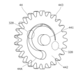
図5は、変形例にかかる第2ギヤ部44の斜視図であり、第2流路との相対位置を点線または一点鎖線で示している。第2ギヤ部44は、上記実施形態の電動弁1における第2ギヤ部34の代わりに用いることができる。第2ギヤ部34以外の構造については、上記実施形態と同様であるため、重複説明を省略する。
2 モータ部
3 ギヤ部
31 ケース基部
315 第1流路
316 第1環状部
32 ギヤケース
328 第2流路
329 第2環状部
33 第1ギヤ部
331 第1軸
332 駆動ギヤ
34,44 第2ギヤ部
341,441 第2軸
343,443 従動ギヤ
342,442 フランジ部
34A~34F 円形リブ
34A1 開口
34B1 遮蔽壁
34C2 第1円形開口
34D2 第2円形開口
34E2 第3円形開口
34F2 第4円形開口
GC ギヤ室
Claims (4)
- モータと、
フランジ部を備え、前記モータにより回転駆動される被駆動部と、
流体の高圧側の流入路と低圧側の排出路とを備え、前記被駆動部を収容する筐体と、を有し、
前記フランジ部は、貫通開口と遮蔽壁と、前記貫通開口及び前記遮蔽壁の周囲に形成された円形リブとを有しており、前記被駆動部の回転位置に応じて、前記貫通開口または前記遮蔽壁が前記流入路と前記排出路の間に配置され、
前記流入路の流体と前記排出路の流体との圧力差に従って、前記フランジ部が前記筐体に対して変位し、前記円形リブが前記筐体の環状部に全周で当接する、
ことを特徴とする電動弁。 - 前記モータの出力軸に駆動ギヤが形成され、前記被駆動部は、前記フランジ部の外周に形成され前記駆動ギヤに噛合する従動ギヤと、前記フランジ部を支持する軸とを有する、
ことを特徴とする請求項1に記載の電動弁。 - 前記フランジ部は、互いに異なる断面積を備えた複数の前記貫通開口を有する、
ことを特徴とする請求項1または2に記載の電動弁。 - 前記円形リブは、前記フランジ部の両側面に、対向してそれぞれ一対形成され、前記環状部は、前記フランジ部を挟んで対向して一対形成されており、
一方の前記円形リブが一方の前記環状部に全周で当接したときは、他方の前記円形リブと他方の前記環状部との間に隙間が形成され、前記流入路側の流体は、前記隙間を介して前記被駆動部を収容する空間に供給される、
ことを特徴とする請求項1~3のいずれか一項に記載の電動弁。
Priority Applications (3)
| Application Number | Priority Date | Filing Date | Title |
|---|---|---|---|
| JP2021118609A JP7410580B2 (ja) | 2021-07-19 | 2021-07-19 | 電動弁 |
| CN202210727686.9A CN115638258A (zh) | 2021-07-19 | 2022-06-23 | 电动阀 |
| JP2023211626A JP2024015519A (ja) | 2021-07-19 | 2023-12-15 | 電動弁 |
Applications Claiming Priority (1)
| Application Number | Priority Date | Filing Date | Title |
|---|---|---|---|
| JP2021118609A JP7410580B2 (ja) | 2021-07-19 | 2021-07-19 | 電動弁 |
Related Child Applications (1)
| Application Number | Title | Priority Date | Filing Date |
|---|---|---|---|
| JP2023211626A Division JP2024015519A (ja) | 2021-07-19 | 2023-12-15 | 電動弁 |
Publications (2)
| Publication Number | Publication Date |
|---|---|
| JP2023014586A JP2023014586A (ja) | 2023-01-31 |
| JP7410580B2 true JP7410580B2 (ja) | 2024-01-10 |
Family
ID=84940625
Family Applications (2)
| Application Number | Title | Priority Date | Filing Date |
|---|---|---|---|
| JP2021118609A Active JP7410580B2 (ja) | 2021-07-19 | 2021-07-19 | 電動弁 |
| JP2023211626A Pending JP2024015519A (ja) | 2021-07-19 | 2023-12-15 | 電動弁 |
Family Applications After (1)
| Application Number | Title | Priority Date | Filing Date |
|---|---|---|---|
| JP2023211626A Pending JP2024015519A (ja) | 2021-07-19 | 2023-12-15 | 電動弁 |
Country Status (2)
| Country | Link |
|---|---|
| JP (2) | JP7410580B2 (ja) |
| CN (1) | CN115638258A (ja) |
Citations (2)
| Publication number | Priority date | Publication date | Assignee | Title |
|---|---|---|---|---|
| JP2004108764A (ja) | 2002-08-30 | 2004-04-08 | Daikin Ind Ltd | 電動膨張弁及び冷凍装置 |
| US20170356552A1 (en) | 2016-06-10 | 2017-12-14 | Ecotec Solutions, Inc. | Multi-orifice plate flow valve |
-
2021
- 2021-07-19 JP JP2021118609A patent/JP7410580B2/ja active Active
-
2022
- 2022-06-23 CN CN202210727686.9A patent/CN115638258A/zh active Pending
-
2023
- 2023-12-15 JP JP2023211626A patent/JP2024015519A/ja active Pending
Patent Citations (2)
| Publication number | Priority date | Publication date | Assignee | Title |
|---|---|---|---|---|
| JP2004108764A (ja) | 2002-08-30 | 2004-04-08 | Daikin Ind Ltd | 電動膨張弁及び冷凍装置 |
| US20170356552A1 (en) | 2016-06-10 | 2017-12-14 | Ecotec Solutions, Inc. | Multi-orifice plate flow valve |
Also Published As
| Publication number | Publication date |
|---|---|
| CN115638258A (zh) | 2023-01-24 |
| JP2024015519A (ja) | 2024-02-02 |
| JP2023014586A (ja) | 2023-01-31 |
Similar Documents
| Publication | Publication Date | Title |
|---|---|---|
| JP7228694B2 (ja) | ボールバルブ | |
| JP5653645B2 (ja) | 多方切換弁 | |
| JP6969895B2 (ja) | バルブ装置 | |
| CN108730553B (zh) | 一种电动阀 | |
| JP6702802B2 (ja) | バルブ装置 | |
| KR20170128087A (ko) | 버터플라이 밸브 | |
| JP7448580B2 (ja) | 電子膨張弁 | |
| JP5265406B2 (ja) | 逆止弁 | |
| US6918408B2 (en) | Valve driving device | |
| US20190136989A1 (en) | Flow path switching valve | |
| JP7410580B2 (ja) | 電動弁 | |
| JP7084042B2 (ja) | パッキン及びロータリバルブ | |
| JP6523734B2 (ja) | バタフライ弁 | |
| JP2004108764A (ja) | 電動膨張弁及び冷凍装置 | |
| JP6946154B2 (ja) | 弁装置及び蒸気タービン | |
| RU2539940C1 (ru) | Термостатический клапан, в частности радиаторный клапан | |
| JP2019152246A (ja) | 電動弁 | |
| JP6955952B2 (ja) | ボールバルブ | |
| JP7036555B2 (ja) | ボールバルブ | |
| JP2018071554A (ja) | 流路切替弁 | |
| KR100540806B1 (ko) | 유량제어장치 | |
| JP7320853B2 (ja) | 流量制御弁 | |
| JP5602477B2 (ja) | 多方切換弁 | |
| JP2019148315A (ja) | 流路切替バルブ | |
| KR100452459B1 (ko) | 회전식 오일 댐퍼 |
Legal Events
| Date | Code | Title | Description |
|---|---|---|---|
| A621 | Written request for application examination |
Free format text: JAPANESE INTERMEDIATE CODE: A621 Effective date: 20220725 |
|
| A977 | Report on retrieval |
Free format text: JAPANESE INTERMEDIATE CODE: A971007 Effective date: 20230524 |
|
| A131 | Notification of reasons for refusal |
Free format text: JAPANESE INTERMEDIATE CODE: A131 Effective date: 20230704 |
|
| A521 | Request for written amendment filed |
Free format text: JAPANESE INTERMEDIATE CODE: A523 Effective date: 20230802 |
|
| TRDD | Decision of grant or rejection written | ||
| A01 | Written decision to grant a patent or to grant a registration (utility model) |
Free format text: JAPANESE INTERMEDIATE CODE: A01 Effective date: 20231121 |
|
| A61 | First payment of annual fees (during grant procedure) |
Free format text: JAPANESE INTERMEDIATE CODE: A61 Effective date: 20231215 |
|
| R150 | Certificate of patent or registration of utility model |
Ref document number: 7410580 Country of ref document: JP Free format text: JAPANESE INTERMEDIATE CODE: R150 |