JP7387150B2 - gaming machine - Google Patents
gaming machine Download PDFInfo
- Publication number
- JP7387150B2 JP7387150B2 JP2019198243A JP2019198243A JP7387150B2 JP 7387150 B2 JP7387150 B2 JP 7387150B2 JP 2019198243 A JP2019198243 A JP 2019198243A JP 2019198243 A JP2019198243 A JP 2019198243A JP 7387150 B2 JP7387150 B2 JP 7387150B2
- Authority
- JP
- Japan
- Prior art keywords
- special
- pseudo
- performance
- display
- jackpot
- Prior art date
- Legal status (The legal status is an assumption and is not a legal conclusion. Google has not performed a legal analysis and makes no representation as to the accuracy of the status listed.)
- Active
Links
- 230000000694 effects Effects 0.000 claims description 201
- 230000002844 continuous effect Effects 0.000 claims description 60
- 238000000034 method Methods 0.000 description 161
- 230000008569 process Effects 0.000 description 159
- 238000004519 manufacturing process Methods 0.000 description 113
- 238000012545 processing Methods 0.000 description 97
- 238000009826 distribution Methods 0.000 description 43
- 238000003860 storage Methods 0.000 description 42
- 230000008859 change Effects 0.000 description 18
- 238000001514 detection method Methods 0.000 description 16
- 239000000872 buffer Substances 0.000 description 15
- 238000010586 diagram Methods 0.000 description 15
- 238000010304 firing Methods 0.000 description 14
- 230000006870 function Effects 0.000 description 13
- 230000001276 controlling effect Effects 0.000 description 9
- 238000010168 coupling process Methods 0.000 description 9
- 238000005859 coupling reaction Methods 0.000 description 9
- 238000011161 development Methods 0.000 description 9
- 238000010924 continuous production Methods 0.000 description 8
- 230000004044 response Effects 0.000 description 8
- 238000012790 confirmation Methods 0.000 description 7
- 238000013461 design Methods 0.000 description 7
- 238000004458 analytical method Methods 0.000 description 6
- 241000274965 Cyrestis thyodamas Species 0.000 description 5
- 230000007704 transition Effects 0.000 description 5
- 230000003864 performance function Effects 0.000 description 4
- 101100400452 Caenorhabditis elegans map-2 gene Proteins 0.000 description 3
- 230000005540 biological transmission Effects 0.000 description 3
- 238000004891 communication Methods 0.000 description 3
- 239000000470 constituent Substances 0.000 description 3
- 230000008054 signal transmission Effects 0.000 description 3
- 241000227653 Lycopersicon Species 0.000 description 2
- 235000007688 Lycopersicon esculentum Nutrition 0.000 description 2
- 101150064138 MAP1 gene Proteins 0.000 description 2
- 238000005401 electroluminescence Methods 0.000 description 2
- 230000014509 gene expression Effects 0.000 description 2
- 230000006872 improvement Effects 0.000 description 2
- 239000004973 liquid crystal related substance Substances 0.000 description 2
- 230000004048 modification Effects 0.000 description 2
- 238000012986 modification Methods 0.000 description 2
- 238000012544 monitoring process Methods 0.000 description 2
- 229920003002 synthetic resin Polymers 0.000 description 2
- 239000000057 synthetic resin Substances 0.000 description 2
- 238000013019 agitation Methods 0.000 description 1
- 230000008901 benefit Effects 0.000 description 1
- 230000004397 blinking Effects 0.000 description 1
- 239000003990 capacitor Substances 0.000 description 1
- 238000005034 decoration Methods 0.000 description 1
- 230000003247 decreasing effect Effects 0.000 description 1
- 238000007599 discharging Methods 0.000 description 1
- 230000002996 emotional effect Effects 0.000 description 1
- 239000011521 glass Substances 0.000 description 1
- 230000000670 limiting effect Effects 0.000 description 1
- 230000014759 maintenance of location Effects 0.000 description 1
- 238000003825 pressing Methods 0.000 description 1
- 230000002265 prevention Effects 0.000 description 1
- 230000009467 reduction Effects 0.000 description 1
- 230000002829 reductive effect Effects 0.000 description 1
- 230000001105 regulatory effect Effects 0.000 description 1
- 230000000717 retained effect Effects 0.000 description 1
- 238000004088 simulation Methods 0.000 description 1
- 238000000638 solvent extraction Methods 0.000 description 1
- 230000003068 static effect Effects 0.000 description 1
- 230000000638 stimulation Effects 0.000 description 1
- 239000000758 substrate Substances 0.000 description 1
- 238000002834 transmittance Methods 0.000 description 1
- 230000001960 triggered effect Effects 0.000 description 1
Images


Classifications
-
- Y—GENERAL TAGGING OF NEW TECHNOLOGICAL DEVELOPMENTS; GENERAL TAGGING OF CROSS-SECTIONAL TECHNOLOGIES SPANNING OVER SEVERAL SECTIONS OF THE IPC; TECHNICAL SUBJECTS COVERED BY FORMER USPC CROSS-REFERENCE ART COLLECTIONS [XRACs] AND DIGESTS
- Y02—TECHNOLOGIES OR APPLICATIONS FOR MITIGATION OR ADAPTATION AGAINST CLIMATE CHANGE
- Y02E—REDUCTION OF GREENHOUSE GAS [GHG] EMISSIONS, RELATED TO ENERGY GENERATION, TRANSMISSION OR DISTRIBUTION
- Y02E60/00—Enabling technologies; Technologies with a potential or indirect contribution to GHG emissions mitigation
- Y02E60/10—Energy storage using batteries
Description
本発明は、パチンコ遊技機等の遊技機に関する。 The present invention relates to a gaming machine such as a pachinko gaming machine.
遊技機の一例であるパチンコ遊技機では、例えば下記特許文献1に記載されているように、始動口への入球に基づいて大当たりであるかの判定が行われ、その判定の結果に基づいて、遊技者に有利な遊技状態に制御される。この文献に記載の遊技機では、大当たりであるかの判定の結果に基づいて、演出図柄を変動表示する変動演出が行われる。この変動演出においては、演出図柄を仮停止表示させた後に再変動表示させる擬似連演出が行われることがあり、擬似連演出の回数が多いほど大当たりへの期待度が高まるようになっている。
In a pachinko game machine, which is an example of a game machine, for example, as described in
ところで、上記特許文献1に記載されているような擬似連演出については、遊技の興趣を向上させるため、未だ改良の余地がある。
By the way, there is still room for improvement in the pseudo-continuous performance as described in
本発明の遊技機は、
所定の演出図柄を変動させて、所定の抽選の結果を示す態様で停止させる変動演出において、一旦停止させた演出図柄を再変動させる擬似連演出を複数回実行可能であり、
所定の煽り演出が成功した場合には前記擬似連演出を実行する遊技機であって、
前記所定の煽り演出は、成功した場合、前記演出図柄を停止させる所定の位置に特殊図柄が停止表示される演出であり、
前記所定の煽り演出が成功した場合に表示される所定の表示に含まれる所定画像が、当該所定の表示から分離されて、次の擬似連演出の実行を示唆する前記特殊図柄として、前記所定の位置に停止表示されることを表現した特定演出を実行可能であり、
前記所定の煽り演出が成功した後で前記特定演出によって次の擬似連演出の実行が示唆される場合、当該次の擬似連演出が実行されるかを煽る前記所定の煽り演出は実行されないことを特徴とする遊技機である。
The gaming machine of the present invention includes:
In a fluctuating performance in which a predetermined performance symbol is varied and stopped in a manner indicating the result of a predetermined lottery, a pseudo-continuous performance in which the once-stopped performance symbol is varied again can be executed multiple times,
A gaming machine that executes the pseudo continuous effect when a predetermined inciting effect is successful,
The predetermined inciting performance is a performance in which, if successful, a special symbol is stopped and displayed at a predetermined position that stops the performance symbol,
A predetermined image included in a predetermined display that is displayed when the predetermined inciting effect is successful is separated from the predetermined display and used as the special symbol that suggests the execution of the next pseudo continuous effect. It is possible to execute a specific effect that expresses that the image is stopped and displayed at a fixed position .
If the specific performance suggests execution of the next pseudo continuous performance after the predetermined provocation performance is successful, the predetermined provocation performance that incites whether the next pseudo continuous performance will be executed is not executed. This is a gaming machine with special features.
本発明の遊技機によれば、演出を通じて遊技の興趣を向上可能である。 According to the game machine of the present invention, it is possible to improve the interest of the game through performance.
以下、本発明の遊技機の実施形態を、図面を参照して具体的に説明する。参照される各図において、同一の部分には同一の符号を付し、同一の部分に関する重複する説明を原則として省略する。なお、本明細書では、記述の簡略化上、情報、信号、物理量又は部材等を参照する記号又は符号を記すことによって、該記号又は符号に対する情報、信号、物理量又は部材等の名称を省略又は略記することがある。また、後述の任意のフローチャートにおいて、任意の複数のステップにおける複数の処理は、処理内容に矛盾が生じない範囲で、任意に実行順序を変更できる又は並列に実行できる。 Embodiments of the gaming machine of the present invention will be specifically described below with reference to the drawings. In each referenced figure, the same parts are given the same reference numerals, and overlapping explanations regarding the same parts will be omitted in principle. In this specification, in order to simplify the description, by writing symbols or codes that refer to information, signals, physical quantities, parts, etc., the names of the information, signals, physical quantities, parts, etc. for the symbols or codes may be omitted or May be abbreviated. Furthermore, in any flowchart described below, the execution order of a plurality of processes in any plurality of steps can be arbitrarily changed or executed in parallel within a range that does not cause inconsistency in the processing contents.
1.遊技機の構造
第1形態のパチンコ遊技機PY1について説明する。最初に、パチンコ遊技機PY1の構造について図1~図5を用いて説明する。なお、以下の説明において、パチンコ遊技機PY1の各部の左右上下方向は、そのパチンコ遊技機PY1に対面する遊技者にとっての(正面視の)左右上下方向のことである。また、「前方」は、パチンコ遊技機PY1から当該パチンコ遊技機PY1に対面する遊技者に近づく方向とし、「後方」は、パチンコ遊技機PY1に対面する遊技者から当該パチンコ遊技機PY1に近づく方向とする。
1. Structure of the gaming machine The first form of pachinko gaming machine PY1 will be explained. First, the structure of the pachinko gaming machine PY1 will be explained using FIGS. 1 to 5. In the following description, the horizontal, vertical, and vertical directions of each part of the pachinko gaming machine PY1 refer to the horizontal, vertical, and vertical directions (as viewed from the front) for the player facing the pachinko gaming machine PY1. Furthermore, "front" is the direction from the pachinko machine PY1 toward the player facing the pachinko machine PY1, and "back" is the direction from the player facing the pachinko machine PY1 toward the pachinko machine PY1. shall be.
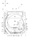
図1に示すように、パチンコ遊技機PY1は、遊技機枠2を備えている。遊技機枠2は、後述する遊技盤ユニットYUが取り付けられる遊技盤取付枠2Aと、遊技盤取付枠2Aにヒンジ2Bを介して回転自在に支持される前枠23mと、を備える。前枠23mは遊技盤取付枠2Aに対して開閉が可能である。前枠23mには、透明板23tが取り付けられている。前枠23mが閉じられているとき、遊技盤取付枠2Aに取り付けられた遊技盤1と透明板23tとは対面する。よって、パチンコ遊技機PY1が遊技店に設置されると、当該パチンコ遊技機PY1の前方にいる遊技者は、透明板23tを通して、遊技盤1に形成された遊技領域6を視認することができる。透明板23tは、透明なガラス板や透明な合成樹脂板等を用いることができる。透明板23tは、パチンコ遊技機PY1の前方から遊技領域6を視認可能であればよい。
As shown in FIG. 1, the pachinko gaming machine PY1 includes a
前枠23mの前面の右下部には、遊技球を発射させるための回転操作が可能なハンドル72kが設けられている。ハンドル72kが操作された量(回転角度)が、遊技球を発射させるために遊技球に与えられる力(後述する発射装置72が発射ソレノイドに駆動させる量)の大きさ(発射強度)に対応付けられている。よって、遊技球は、ハンドル72kの回転操作に応じた発射強度で発射される。また、前枠23mの前面の下部中央には、前方に向けて大きく突出した下部装飾体36が設けられている。下部装飾体36の上面には、ハンドル72kに供給される遊技球を貯留するための上皿34が形成されている。また、下部装飾体36の正面の下部中央には、上皿34に収容しきれない余剰の遊技球を貯留するための下皿35が設けられている。
A
下部装飾体36の上面の上皿34より前方側には、下方に押下操作可能な第1入力装置(以下「通常ボタン」)40が設けられている。また、前枠23mの表面の右縁部から前方に突出して形成されている右部装飾体32において、下方に押下操作可能な第2入力装置(以下「特殊ボタン」)41が設けられている。
A first input device (hereinafter referred to as "normal button") 40 that can be pressed down is provided on the upper surface of the lower
また、前枠23mの表面の上部から前方に突出して形成されている上部装飾体31の底面に、音を出力可能なスピーカ52が設けられている。スピーカ52は、左側に配置された左スピーカ52Lと、右側に配置された右スピーカ52Rと、からなる。また、前枠23mの右縁部と、下部装飾体36における正面の下皿35の左側および右側とに、発光可能な枠ランプ53が設けられている。さらに、前枠23mの左縁部および右縁部の上側には、遊技興趣を高めることを目的とする演出装置としての可動式の枠可動装置58が取り付けられている。枠可動装置58は、左側に配置された左枠可動装置58Lと、右側に配置された右枠可動装置58Rと、で構成される。
Further, a
なお、遊技機枠2に設けられる部材や装置の位置や数は、遊技に支障をきたさない範囲で適宜に変更可能である。
Note that the positions and numbers of members and devices provided in the
次に、遊技盤ユニットYUについて、主に図2~図5を用いて説明する。遊技盤ユニットYUは、遊技盤1と、遊技盤1の背面側に取り付けられた演出用ユニット1Uと、を有する。最初に、遊技盤1について説明する。遊技盤1は透明な合成樹脂板で構成されている。遊技盤1の略中央には正面視略円形の開口部1Aが形成されている。開口部1Aに沿って、遊技球が流下可能な遊技領域6を区画するための略リング状の内側壁部1Bが前方に突出して形成されている。また、内側壁部1Bの外側にも、遊技領域6を区画するための略リング状の外側壁部1Cが前方に突出して形成されている。
Next, the game board unit YU will be explained using mainly FIGS. 2 to 5. The game board unit YU includes a
遊技盤1の前面には、内側壁部1B、外側壁部1Cなどで囲まれた遊技領域6が形成されている。すなわち、遊技盤1の前面が、内側壁部1Bおよび外側壁部1Cによって、遊技領域6とそれ以外の領域とに仕切られている。
On the front surface of the
遊技領域6は、ハンドル72kの操作によって発射された遊技球が流下可能な領域であり、パチンコ遊技機PY1で遊技を行うために設けられている。なお、遊技領域6には、多数の遊技くぎ(図示なし)が突設されている。遊技くぎは、遊技領域6に進入して遊技領域6を流下する遊技球を、後述する第1始動口11、第2始動口12、一般入賞口10、ゲート13、第1大入賞口14、および、第2大入賞口15などに適度に誘導する経路を構成している。なお、第1始動口11や第2始動口12といった始動口を入球口と称し、第1大入賞口14や第2大入賞口15といった大入賞口を特別入賞口あるいは特定の入賞口と称し、ゲートを通過口あるいは通過領域と称することができるものとする。
The
遊技領域6の中央付近には、開口部1Aの周縁を装飾するセンター枠(センター装飾体)61が設けられている。センター枠61には、後述する第1始動口11へ遊技球を誘導可能なステージや、ステージへ遊技球を誘導可能なワープが設けられている。
Near the center of the
また、遊技領域6には、遊技球が入球可能な第1始動口11が形成された第1始動入賞装置11Dと、第2始動口12への入球を可能または不可能にさせる第2始動入賞装置(所謂「電チュー」)12Dと、が設けられている。
Also, in the
第1始動入賞装置11Dは不動である。そのため、第1始動口11は、遊技球の入球し易さが変化せずに一定(不変)である。遊技球の第1始動口11への入賞は、第1特別図柄(以下、「特図1」という)の抽選(後述の特図1関係乱数の取得と判定:以下、「特図1抽選」ともいう)および特図1の可変表示の契機となっている。また、遊技球が第1始動口11へ入賞すると、所定個数(本形態では4個)の遊技球が賞球として払い出される。
The first
電チュー12Dは、作動可能な電チュー開閉部材12kを備えている。電チュー開閉部材12kは、通常は(通常状態では)、第2始動口12への遊技球の入球が不可能な閉鎖位置にある。そして、特別状態になると、第2始動口12への遊技球の入球が可能な開放位置に移動する。このように、電チュー開閉部材12kが開放位置に移動することを第2始動口12または電チュー12Dの「開状態」ともいい、開状態であるときだけ遊技球の第2始動口12への入球が可能となる。一方、電チュー開閉部材12kが閉鎖位置にあることを第2始動口12または電チュー12Dの「閉状態」ともいう。また、第2始動口12または電チュー12Dが「開状態」になることを「電チュー12Dが開放する」ともいい、電チュー12Dが「閉状態」になることを「電チュー12Dが閉鎖する」ともいう。
The
遊技球の第2始動口12への入賞は、第2特別図柄(以下、「特図2」という)の抽選(後述の特図2関係乱数の取得と判定:以下、「特図2抽選」ともいう)および特図2の可変表示の契機となっている。また、遊技球が第2始動口12へ入賞すると、所定個数(本形態では4個)の遊技球が賞球として払い出される。なお、遊技領域6には、遊技球を第2始動口12へ誘導する誘導ステージ12gが設けられている。
Winning a game ball into the
また、遊技領域6には、遊技球が入球可能な一般入賞口(普通入賞口)10が設けられている。遊技球が一般入賞口10へ入賞すると、所定個数(本形態では3個)の遊技球が賞球として払い出される。
Further, the
また、遊技領域6には、遊技球が通過可能なゲート13が設けられている。遊技球のゲート13の通過は、普通図柄(以下、「普図」という)の抽選(すなわち普通図柄乱数の取得と判定:以下、「普図抽選」という)および普図の可変表示の契機となっている。補助遊技が実行されることによって電チュー12Dを開放する。すなわち、補助遊技は、電チュー12Dの開放を伴う遊技である。
Further, the
また、遊技領域6には、遊技球が入球可能な第1大入賞口14が形成された第1大入賞装置14D(以下、「通常AT14D」ともいう)が設けられている。第1大入賞装置14Dは、開状態と閉状態とに作動可能な通常AT開閉部材14kを備える。通常AT開閉部材14kの作動により第1大入賞口14が開閉する。通常AT開閉部材14kは、通常では第1大入賞口14を塞ぐ閉状態になっており、遊技球が第1大入賞口14の中に入球することは不可能である。通常AT開閉部材14kが開状態に作動すると、遊技球が第1大入賞口14の中に入球することが可能になる。このように、通常AT開閉部材14kが開状態であるときだけ遊技球の第1大入賞口14への入球が可能となる。遊技球が第1大入賞口14へ入賞すると、所定個数(本形態では15個)の遊技球が賞球として払い出される。
Further, the
また、遊技領域6には、遊技球が入球可能な第2大入賞口15が形成された第2大入賞装置15D(以下、「VAT15D」ともいう)が設けられている。第2大入賞装置15Dは、作動可能なVAT開閉部材15kを備えている。VAT開閉部材15kは、通常では第2大入賞口15を塞いでいる。VAT開閉部材15kは開状態をとることができる。VAT開閉部材15kが開状態であるときだけ遊技球の第2大入賞口15への入球が可能となる。一方、VAT開閉部材15kが第2大入賞口15を塞いでいる状態を「閉状態」ともいう。このように、VAT開閉部材15kの作動によって第2大入賞口15が開閉する。遊技球が第2大入賞口15へ入賞すると、所定個数(本形態では15個)の遊技球が賞球として払い出される。
Further, the
ここで、図3を用いて、第2大入賞装置15Dについて詳細に説明する。第2大入賞装置15Dの内部には、第2大入賞口15に入球した遊技球を検知し、遊技球を下方へ通過させることが可能なゲート状の第2大入賞口センサ15aが設けられている。
Here, the second grand
第2大入賞口センサ15aの下流域には、遊技球が通過(進入)可能な特定領域16と非特定領域17とが設けられている。第2大入賞口センサ15aを通過した遊技球は、振分装置16Dによって、特定領域16か非特定領域17かに振り分けられる。振分装置16Dは、略矩形状の平板からなる振分部材16kと、振分部材16kを駆動する振分ソレノイド16sとを備えている。振分部材16kは、振分ソレノイド16sの駆動により、左右にスライド可能に構成されている。
A
振分ソレノイド16sが通電されていないとき、振分部材16kは特定領域16への遊技球の通過を妨げる第1状態(通過阻止状態:図3(A)の正面視で振分部材16kの左端が特定領域16の左端よりやや右側に位置し、振分部材16kが特定領域16をその直上で覆う状態)にある。振分部材16kが第1状態にあるときは、第2大入賞口15に入賞した遊技球は、第2大入賞口センサ15aを通過した後、特定領域16を通過することは不可能であり、非特定領域17を通過する。この第2大入賞口15から非特定領域17まで流下する遊技球のルートを第1のルートという。
When the
一方、振分ソレノイド16sが通電されているとき、振分部材16kは遊技球の特定領域16の通過(進入)を許容する第2状態(通過許容状態:図3(B)の正面視で振分部材16kの左端が特定領域16の右端よりやや左側に位置し、振分部材16kが特定領域16をその直上で覆わず、特定領域16の直上が開放している状態)にある。振分部材16kが第2状態にあるときは、第2大入賞口15に入賞した遊技球は、第2大入賞口センサ15aを通過したあと特定領域16を通過容易である。この第2大入賞口15から特定領域16まで流下する遊技球のルートを第2のルートという。
On the other hand, when the
なお、基本的に、振分部材16kは第1状態で保持されている。すなわち、第1状態が、振分部材16kの通常の状態であるといえる。そして、所定のラウンド遊技(例えば16R)においてのみ、振分ソレノイド16sが通電され、第2状態に変化することができる。なお、振分部材16kの作動態様は適宜変更可能である。
Note that basically, the
特定領域16と非特定領域17には、各領域16,17を通過(進入)した遊技球を検知し、遊技球を下方へ通過させる特定領域センサ16a、非特定領域センサ17aが設けられている。
The
なお、第1大入賞装置14Dおよび第2大入賞装置15Dは、遊技に支障をきたさない範囲で、一方だけを設けるようにすることが可能である。また、遊技性に応じて、第1大入賞装置14Dのような、特定領域や振分装置のない大入賞装置を2つ設ける構成とすることが可能である。また、第1大入賞装置14Dと第2大入賞装置15Dとが設けられているものの、遊技性に応じて、第1大入賞装置14Dだけを利用することとしたり、第2大入賞装置15Dだけを利用することとしたりすることが可能である。なお、第1大入賞装置14Dだけを利用する構成とした場合には、第2大入賞装置15Dに関する処理は行われないものとし、第2大入賞装置15Dだけを利用する構成とした場合には、第1大入賞装置14Dに関する処理は行われないものとする。
Note that it is possible to provide only one of the first
また、図2に示すように、遊技領域6の略最下部には、遊技領域6へ打ち込まれたもののいずれの入賞口にも入賞しなかった遊技球を遊技領域6の外部へ排出する2つのアウト口19が設けられている。また、遊技盤1には、発光可能な盤ランプ54が設けられている。
In addition, as shown in FIG. 2, at approximately the bottom of the
ところで、遊技球が流下可能な遊技領域6は、左右方向の中央より左側の左遊技領域6A(第1遊技領域)と、右側の右遊技領域6B(第2遊技領域)と、に分けることができる。遊技球が左遊技領域6Aを流下するように遊技球を発射させるハンドル72kの操作態様を「左打ち」という。一方、遊技球が右遊技領域6Bを流下するように遊技球を発射させるハンドル72kの操作態様を「右打ち」という。パチンコ遊技機PY1において、左打ちにて遊技球を発射したときに遊技球が流下可能な流路を、第1流路R1といい、右打ちにて遊技球を発射したときに遊技球が流下可能な流路を、第2流路R2という。第1流路R1および第2流路R2は、多数の遊技くぎなどによっても構成されている。
By the way, the
第1流路R1上には、第1始動口11と、2つの一般入賞口10と、が設けられている。よって、遊技者は、左打ちにより第1流路R1を流下するように遊技球を発射させることで、第1始動口11、または、一般入賞口10への入賞を狙うことができる。一方、第2流路R2上には、第2始動口12と、一般入賞口10と、ゲート13と、第1大入賞口14と、第2大入賞口15と、が設けられている。よって、遊技者は、右打ちにより第2流路R2を流下するように遊技球を発射させることで、ゲート13の通過や、第2始動口12、一般入賞口10、第1大入賞口14、または、第2大入賞口15への入賞を狙うことができる。
A
なお、何れの入賞口(第1始動口11、第2始動口12、一般入賞口10、第1大入賞口14、および第2大入賞口15)にも入球しなかった遊技球は、アウト口19へ誘導されて排出される。また、各入賞口への入賞による賞球数は、適宜に設定することが可能である。
In addition, game balls that did not enter any of the winning holes (first starting
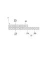
また、遊技盤1の前面に形成された遊技領域6の下方の左隣(遊技領域6以外の部分)には表示器類8が配置されている。図4に示すように、表示器類8には、特図1を可変表示する特図1表示器81a、特図2を可変表示する特図2表示器81b、及び、普図を可変表示する普図表示器82が含まれている。また、表示器類8には、後述する特図1保留数(U1:特図1表示器81aによる特図1の可変表示が保留されている数)を表示する特図1保留表示器83a、および後述する特図2保留数(U2:特図2表示器81bによる特図2の可変表示が保留されている数)を表示する特図2保留表示器83bが含まれている。
Further, a
特図1の可変表示は、第1始動口11への遊技球の入賞を契機に特図1抽選が行われると実行される。また、特図2の可変表示は、第2始動口12への遊技球の入賞を契機に特図2抽選が行われると実行される。なお、以下の説明では、特図1および特図2を総称して特図あるいは特別図柄といい、特図1抽選および特図2抽選を総称して特図抽選という。また、特図1表示器81aおよび特図2表示器81bを総称して特図表示器81という。さらに、特図1保留表示器83aおよび特図2保留表示器83bを総称して特図保留表示器83という。
The variable display of the special figure 1 is executed when the special figure 1 lottery is held in response to the landing of a game ball into the
特図の可変表示は、特図抽選の結果を報知する。特図の可変表示では、特図が可変表示したあと停止表示する。停止表示される特図(停止特図、可変表示の表示結果として導出表示される特別図柄)は、特図抽選によって複数種類の特図の中から選択された一つの特図である。停止特図が予め定めた特定の特図(特定の停止態様の特図すなわち大当たり図柄)である場合には、大入賞口(第1大入賞口14及び第2大入賞口15)を開放させる大当たり遊技(特別遊技の一例)が行われる。なお、大当たり遊技が行われている遊技状態を大当たり遊技状態という。大当たり遊技状態は、遊技者に有利な特別遊技状態の一例である。
The variable display of the special figure notifies the result of the special figure lottery. In the variable display of the special figure, the special figure is displayed variably and then stopped. The special figure that is stopped and displayed (stopped special figure, special figure derived and displayed as a display result of the variable display) is one special figure selected from a plurality of types of special figures by a special figure lottery. When the stopping special symbol is a predetermined specific special symbol (a special symbol with a specific stopping pattern, that is, a jackpot symbol), the grand prize opening (the first
特図表示器81は、例えば横並びに配された8個のLED(Light Emitting Diode)から構成され、その点灯態様によって特図抽選の結果に応じた特図を表示する。例えば特図抽選の結果が大当たり(後述の複数種類の大当たりのうちの一つ)である場合には、特図表示器81は、「□□■■□□■■」(□:点灯、■:消灯)というように左から1,2,5,6番目にあるLEDの点灯で構成される大当たり図柄を表示する。また、特図抽選の結果がハズレである場合には、特図表示器81は、「■■■■■■■□」というように一番右にあるLEDのみの点灯で構成されるハズレ図柄を表示する。なお、特図抽選の結果に対応するLEDの点灯態様は限定されず、適宜に設定することができる。よって、例えば、ハズレ図柄として全てのLEDを消灯させてもよい。
The
また、特図の可変表示において、特図が停止表示される前には所定の変動時間にわたって特図の可変表示がなされる。特図の可変表示の態様は、例えば左から右へ光が繰り返し流れるように各LEDが点灯する態様である。なお、特図の可変表示の態様は、特に限定されず、各LEDが停止表示(特定の態様での点灯表示)されていなければ、全LEDが一斉に点滅するなど適宜に設定してよい。 Further, in the variable display of the special figure, the variable display of the special figure is performed for a predetermined variable time before the special figure is stopped and displayed. The variable display mode of the special figure is, for example, a mode in which each LED lights up so that light repeatedly flows from left to right. Note that the manner of variable display of the special figure is not particularly limited, and may be set as appropriate, such as when all LEDs flash at once if each LED is not displayed in a stopped state (lit display in a specific manner).
ところで、パチンコ遊技機PY1では、第1始動口11または第2始動口12への遊技球の入賞(入球)があると、特図抽選などを行うための各種乱数(判定情報の一例)が取得されることがある。この各種乱数は、特図保留として後述の特図保留記憶部105に一旦記憶される。なお、以下において、第1始動口11への遊技球の入賞(入球)により取得された各種乱数のことを「特図1関係乱数」といい、第2始動口12への遊技球の入賞(入球)により取得された各種乱数のことを「特図2関係乱数」という。ここで、特図1関係乱数は、特図1保留として、特図保留記憶部105の中の特図1保留記憶部105aに記憶される。一方、特図2関係乱数は、特図2保留として、特図保留記憶部105の中の特図2保留記憶部105bに記憶される。特図1保留記憶部105aに記憶可能な特図1保留の数(特図1保留数)および特図2保留記憶部105bに記憶可能な特図2保留の数(特図2保留数)には上限(本形態では4個)が設定されている。特図1保留数や特図2保留数の上限は適宜変更可能であり、上限を「無し」としてもよい。なお、以下において、特図1保留と特図2保留を総称して「特図保留」といい、特図1保留数と特図2保留数を総称して「特図保留数」という。また、特図1関係乱数と特図2関係乱数とを総称して「特図関係乱数」という。
By the way, in the pachinko game machine PY1, when a game ball hits the
パチンコ遊技機PY1では、遊技球が第1始動口11または第2始動口12へ入賞した後すぐに特図の可変表示が行われない場合、具体的には、特図の可変表示の実行中や大当たり遊技の実行中に入賞があった場合、その入賞に対する特図の可変表示(あるいは、特図抽選の権利)を留保することができる。特図保留記憶部105に記憶された特図保留は、その特図保留に基づく特図の可変表示が可能となったときに消化される。すなわち、特図保留の消化とは、その特図保留に対応する特図関係乱数等を判定して、その判定結果を示すための特図の可変表示を実行することをいう。
In the pachinko game machine PY1, if the variable display of the special figure is not performed immediately after the game ball enters the
そして、特図保留数は、特図保留表示器83に表示される。特図1保留表示器83aと特図2保留表示器83bのそれぞれは、例えば4個のLEDで構成されており、特図保留数の分だけLEDを点灯させることにより特図保留数を表示することが可能である。
Then, the special figure reservation number is displayed on the special
また、普図の可変表示は、普図抽選の結果を報知する。普図の可変表示では、普図が可変表示したあと停止表示する。停止表示される普図(停止普図、可変表示の表示結果として導出表示される普図)は、普図抽選によって複数種類の普図の中から選択された一つの普図である。停止表示された普図が予め定めた特定の普図(所定の停止態様の普図すなわち当たり図柄)である場合には、第2始動口12(電チュー12D)を開放させる補助遊技が行われる。
In addition, the variable display of the general map notifies the result of the general map lottery. In the variable display of a general map, the general map is displayed variably and then stopped. The general map that is stopped and displayed (the stationary general map, the general map derived and displayed as a display result of the variable display) is one general map selected from among a plurality of types of general maps by lottery. If the stopped and displayed general figure is a predetermined specific ordinary figure (ordinary figure with a predetermined stop mode, that is, a winning symbol), an auxiliary game is performed in which the second starting port 12 (
普図表示器82は、例えば2個のLEDから構成されており、その点灯態様によって普図抽選の結果に応じた普図を表示する。普図抽選の結果が当たりである場合には、普図表示器82は、「□□」(□:点灯、■:消灯)というように両LEDの点灯で構成される当たり図柄を表示する。また普図抽選の結果がハズレである場合には、「■□」というように右のLEDのみの点灯で構成されるハズレ図柄を表示する。ハズレ図柄として全てのLEDを消灯させる態様を採用してもよい。なお、普図抽選の結果に対応するLEDの点灯態様は限定されず、適宜に設定することができる。
The common
また、普図が停止表示される前には所定の変動時間にわたって普図の可変表示が行われる。普図の可変表示の態様は、例えば両LEDが交互に点灯するという態様である。なお、普図の可変表示の態様は、特に限定されず、各LEDが停止表示(特定の態様での点灯表示)されていなければ、全LEDが一斉に点滅するなど適宜に設定してもよい。 Further, before the regular map is stopped and displayed, the regular map is variablely displayed for a predetermined variable time. The mode of variable display of the ordinary map is, for example, a mode in which both LEDs are lit alternately. Note that the mode of variable display of the general map is not particularly limited, and may be set as appropriate, such as all LEDs blinking at once, unless each LED is displayed in a stopped state (lit display in a specific mode). .
パチンコ遊技機PY1では、遊技球がゲート13を通過すると、普図抽選を行うための普通図柄乱数(判定情報の一例)が取得されることがある。この乱数は、普図の可変表示または補助遊技が実行されていないことを条件に、後述の普図保留記憶部106に記憶される。普図保留記憶部106に記憶可能な普図保留の数(普図保留数)には上限(本形態では4個)が設定されている。普図保留数の上限は適宜変更可能であり、上限を「無し」としてもよい。なお、以下において、遊技球がゲート13を通過することにより取得された普通図柄乱数のことを「普図関係乱数」ともいう。また、本形態では、普図保留数を表示する普図保留表示器を設けていないが、普図保留表示器を表示器類8に加えてもよい。普図保留表示器としては、例えば特図保留表示器83と同様の構成のものを採用することが可能である。
In the pachinko game machine PY1, when a game ball passes through the
次に、図5を用いて、遊技盤1の背面に取り付けられた演出用ユニット1Uについて説明する。演出用ユニット1Uは、主に演出を行う複数の装置をユニット化したものである。演出用ユニット1Uには、画像表示装置50、第1盤可動装置(以下「盤上可動装置」)55、第2盤可動装置(以下「盤下可動装置」)56が搭載されている。
Next, the
画像表示装置50は、例えば20インチの3D液晶ディスプレイで構成され、3D画像を表示可能な表示部50aを具備する。なお、画像表示装置50は、画像を表示することが可能であれば、複数枚の液晶ディスプレイで構成されるものや、EL(Electro Luminescence)ディスプレイで構成されるもの等、他の表示装置であってもよい。
The
盤上可動装置55は、表示部50aに沿って移動可能に構成され、装飾が施された盤上可動体55kを具備する。盤下可動装置56は、表示部50aに沿って移動可能に構成され、装飾が施された盤下可動体56kを具備する。
The on-board
図5(A)は、盤上可動体55kおよび盤下可動体56kが作動していない通常の待機状態(初期位置)で保持されている様子を概略化して表している。盤上可動装置55の駆動源が駆動すると、盤上可動体55kは下向きに移動(下降)し、盤下可動装置56の駆動源が駆動すると、盤下可動体56kは上向きに移動(上昇)する。このとき、画像表示装置50は下降した盤上可動体55kまたは上昇した盤下可動体56kに覆われ、画像表示装置50は視認困難となる。
FIG. 5A schematically shows how the above-panel
なお、遊技盤ユニットYUに設けられる部材や装置の位置や数は、遊技に支障をきたさない範囲で適宜に変更可能である。 Note that the positions and numbers of members and devices provided in the game board unit YU can be changed as appropriate within a range that does not interfere with the game.
2.遊技機の電気的構成
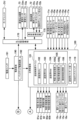
次に、図6~図7に基づいて、パチンコ遊技機PY1における電気的な構成を説明する。図6~図7に示すように、パチンコ遊技機PY1は、特図抽選、特図の可変表示、大当たり遊技、後述する遊技状態の設定、普図抽選、普図の可変表示、補助遊技などの遊技利益に関する制御(遊技の進行)を行う遊技制御基板(以下「主制御基板」)100、主制御基板100による遊技の進行に応じた遊技演出(特図変動演出、保留演出、操作演出、大当たり遊技演出など)や客待ち演出などの演出に関する制御を行う演出制御基板(以下「サブ制御基板」)120、および、遊技球の払い出しに関する制御などを行う払出制御基板170等を、遊技盤1の画像表示装置50よりさらに背面側に備えている。主制御基板100を、遊技の制御を行う遊技制御部(メイン制御部)と位置づけることができる。また、サブ制御基板120を、後述する画像制御基板140、ランプ制御回路151、および音声制御回路161とともに、演出の制御を行う演出制御部(サブ制御部)と位置づけることができる。なお、演出制御部は、少なくともサブ制御基板120を備え、演出手段(画像表示装置50、スピーカ52、枠ランプ53、盤ランプ54、および、可動装置55,56,58等)を用いた各種の演出を制御可能であればよい。
2. Electrical Configuration of Gaming Machine Next, the electrical configuration of the pachinko gaming machine PY1 will be explained based on FIGS. 6 and 7. As shown in FIGS. 6 and 7, the pachinko gaming machine PY1 has various functions such as a special drawing lottery, a variable display of special drawings, a jackpot game, a game state setting described later, a general drawing drawing, a variable display of a general drawing, and auxiliary games. A game control board (hereinafter referred to as the "main control board") 100 that controls gaming profits (progress of the game), and a game performance (special figure variation performance, hold performance, operation performance, jackpot) according to the progress of the game by the main control board 100 A performance control board (hereinafter referred to as "sub control board") 120 that controls performances such as game performances (game performances, etc.) and customer waiting performances, and a
また、パチンコ遊技機PY1は、電源基板190を備えている。電源基板190は、主制御基板100、サブ制御基板120、及び払出制御基板170に対して電力を供給するとともに、これらの基板を介してその他の機器に対して必要な電力を供給する。電源基板190には、バックアップ電源回路192が設けられている。バックアップ電源回路192は、パチンコ遊技機PY1に対して電力が供給されていない場合に、後述する主制御基板100の遊技用RAM104やサブ制御基板120の演出用RAM124に対して電力を供給する。従って、主制御基板100の遊技用RAM104やサブ制御基板120の演出用RAM124に記憶されている情報は、パチンコ遊技機PY1の電断時であっても保持される。また、電源基板190には、電源スイッチ191が接続されている。電源スイッチ191のON/OFF操作により、電源の投入/遮断が切り換えられる。なお、主制御基板100の遊技用RAM104に対するバックアップ電源回路を主制御基板100に設けたり、サブ制御基板120の演出用RAM124に対するバックアップ電源回路をサブ制御基板120に設けたりしてもよい。
Furthermore, the pachinko game machine PY1 includes a
図6に示すように、主制御基板100には、プログラムに従ってパチンコ遊技機PY1の遊技の進行を制御する遊技制御用ワンチップマイコン(以下「遊技制御用マイコン」)101が実装されている。遊技制御用マイコン101には、遊技の進行を制御するためのプログラムやテーブル等を記憶した遊技用ROM(Read Only Memory)103、ワークメモリとして使用される遊技用RAM(Random Access Memory)104、および遊技用ROM103に記憶されたプログラムを実行する遊技用CPU(Central Processing Unit)102が含まれている。
As shown in FIG. 6, the
遊技用ROM103には、後述する主制御メイン処理やメイン側タイマ割り込み処理などを行うためのプログラムが格納されている。また、遊技用ROM103には、後述する大当たり判定テーブル、大当たり図柄種別判定テーブル、リーチ判定テーブル、特図変動パターン判定テーブル、先読み判定テーブル、大当たり遊技制御テーブル、当たり判定テーブル、普図変動パターン判定テーブル、補助遊技制御テーブルなどが格納されている。なお、遊技用ROM103は外付けであってもよい。また、遊技用RAM104には、前述した特図保留記憶部105や普図保留記憶部106などが設けられている。
The
また、主制御基板100には、データや信号の入出力を行うための遊技用I/O(Input/Output)ポート部118、および遊技用RAM104に記憶されている情報を遊技用CPU102にクリアさせるためのRAMクリアスイッチ119が実装されている。
The
また、主制御基板100には、所定の中継基板(図示なし)を介して各種センサ類やアクチュエータ類が接続されている。そのため、主制御基板100には、各種センサ類が出力した信号が入力する。また、主制御基板100は、各種アクチュエータ類に信号を出力する。
Furthermore, various sensors and actuators are connected to the
主制御基板100に接続されている各種センサ類には、第1始動口センサ11a、第2始動口センサ12a、一般入賞口センサ10a、ゲートセンサ13a、第1大入賞口センサ14a、第2大入賞口センサ15a、特定領域センサ16a、および、非特定領域センサ17aが含まれている。
Various sensors connected to the
第1始動口センサ11aは、第1始動口11に入賞した遊技球を検知する。第2始動口センサ12aは、第2始動口12に入賞した遊技球を検知する。一般入賞口センサ10aは、一般入賞口10に入賞した遊技球を検知する。一般入賞口センサ10aは、一般入賞口10毎に設けられている。ゲートセンサ13aは、ゲート13に設けられており、ゲート13を通過した遊技球を検知する。第1大入賞口センサ14aは、第1大入賞口14に入賞した遊技球を検知する。第2大入賞口センサ15aは、第2大入賞口15に入賞した遊技球を検知する。特定領域センサ16aは、特定領域16を通過(特定領域16に進入)した遊技球を検知する。非特定領域センサ17aは、非特定領域17を通過(非特定領域17に進入)した遊技球を検知する。各センサは、遊技球を検知すると、その検知内容に応じた信号を主制御基板100に出力する。
The first
なお、主制御基板100に接続されるセンサの種類や数は、遊技に支障をきたさない範囲で適宜に変更可能である。
Note that the type and number of sensors connected to the
また、主制御基板100に接続されている各種アクチュエータ類には、電チューソレノイド12s、第1大入賞口ソレノイド14s、第2大入賞口ソレノイド15sおよび振分ソレノイド16sが含まれている。電チューソレノイド12sは、電チュー12Dの電チュー開閉部材12kを駆動する。第1大入賞口ソレノイド14sは、第1大入賞装置14Dの通常AT開閉部材14kを駆動する。第2大入賞口ソレノイド15sは、第2大入賞装置15DのVAT開閉部材15kを駆動する。振分ソレノイド16sは、振分装置16Dの振分部材16kを駆動する。
Further, the various actuators connected to the
なお、主制御基板100に接続されるアクチュエータの種類や数は、遊技に支障をきたさない範囲で適宜に変更可能である。
Note that the type and number of actuators connected to the
さらに主制御基板100には、表示器類8(特図表示器81、普図表示器82、および、特図保留表示器83)が接続されている。これらの表示器類8の表示制御は、遊技制御用マイコン101によりなされる。
Further, the
また主制御基板100は、払出制御基板170に各種コマンドを送信するとともに、払い出し監視のために払出制御基板170から信号を受信する。払出制御基板170には、カードユニットCU(パチンコ遊技機PY1に隣接して設置され、挿入されているプリペイドカード等の情報に基づいて球貸しを可能にするもの)、および賞球払出装置73が接続されているとともに、発射制御回路175を介して発射装置72が接続されている。なお、発射装置72には、ハンドル72k(図1参照)が含まれる。
The
払出制御基板170は、遊技制御用マイコン101からの信号や、接続されたカードユニットCUからの信号に基づいて、賞球払出装置73の賞球モータ73mを駆動して賞球の払い出しを行ったり、貸球の払い出しを行ったりする。払い出される遊技球は、その計数のための賞球センサ73aにより検知されて、賞球センサ73aによる検知信号が払出制御基板170に出力される。
The
また、発射装置72には、遊技者などの人のハンドル72k(図1参照)への接触を検知可能なタッチスイッチ72aが設けられている。遊技者によるハンドル72kの操作があった場合には、タッチスイッチ72aが遊技者のハンドル72kへの接触を検知し、検知信号を払出制御基板170に出力する。また、発射装置72には、ハンドル72kの回転角度(操作量)を検出可能な発射ボリュームつまみ72bが接続されている。発射装置72は、発射ボリュームつまみ72bが検出したハンドル72kの回転角度に応じた強さで遊技球が発射されるよう発射ソレノイド72sを駆動させる。なお、パチンコ遊技機PY1においては、ハンドル72kへの回転操作が維持されている状態では、約0.6秒毎に1球の遊技球が発射されるようになっている。
Further, the
また主制御基板100は、遊技の進行に応じて、サブ制御基板120に対し、遊技に関する情報を含んだ各種コマンドを送信する。サブ制御基板120は、主制御基板100から送られる各種コマンドに基づいて、主制御基板100による遊技の進行状況(遊技の制御内容)を把握することができる。なお、主制御基板100とサブ制御基板120との接続は、主制御基板100からサブ制御基板120への信号の送信のみが可能な単方向通信接続となっている。すなわち、主制御基板100とサブ制御基板120との間には、通信方向規制手段としての図示しない単方向性回路(例えばダイオードを用いた回路)が介在している。
Further, the
図7に示すように、サブ制御基板120には、プログラムに従ってパチンコ遊技機PY1の演出を制御する演出制御用ワンチップマイコン(以下「演出制御用マイコン」)121が実装されている。演出制御用マイコン121には、主制御基板100による遊技の進行に伴って演出を制御するためのプログラム等を記憶した演出用ROM123、ワークメモリとして使用される演出用RAM124、および演出用ROM123に記憶されたプログラムを実行する演出用CPU122が含まれている。
As shown in FIG. 7, the
また、演出用ROM123には、後述するサブ制御メイン処理、受信割り込み処理、1msタイマ割り込み処理、および、10msタイマ割り込み処理などを行うためのプログラムが格納されている。なお、演出用ROM123は外付けであってもよい。
Further, the
また、サブ制御基板120には、データや信号の入出力を行うための演出用I/Oポート部138、およびRTC(Real Time Clock)139が実装されている。RTC139は、現時点の日時(日付及び時刻)を計測する。RTC139は、パチンコ遊技機PY1に、所定の島電源供給装置(図示なし)から電力が供給されているときにはその電力によって動作し、島電源供給装置から電力が供給されていないときには、電源基板190が備えるバックアップ電源回路192から供給される電力によって動作する。このため、RTC139は、パチンコ遊技機PY1の電源が投入されていないときにも現在の日時を計測することが可能である。なお、RTC139に対するバックアップ電源回路をサブ制御基板120に設けてもよい。バックアップ電源回路には、コンデンサや内蔵電池(ボタン電池等)を含む回路を採用することができる。
Furthermore, the
サブ制御基板120には、画像制御基板140が接続されている。サブ制御基板120の演出制御用マイコン121は、主制御基板100から受信したコマンドに基づいて、すなわち、主制御基板100による遊技の進行に応じて、画像制御基板140の画像用CPU141に画像表示装置50の表示制御を行わせる。なお、サブ制御基板120と画像制御基板140との接続は、サブ制御基板120から画像制御基板140への信号の送信と、画像制御基板140からサブ制御基板120への信号の送信の双方が可能な双方向通信接続となっている。
An
画像制御基板140は、画像制御のためのプログラム等を記憶した画像用ROM142、ワークメモリとして使用される画像用RAM143、及び、画像用ROM142に記憶されたプログラムを実行する画像用CPU141を備えている。また、画像制御基板140は、画像表示装置50に表示される画像のデータを記憶したCGROM145、CGROM145に記憶されている画像データの展開等に使用されるVRAM146、及び、VDP(Video Display Processor)144を備えている。勿論、これらの電子部品の全部又は一部がワンチップで構成されていてもよい。CGROM145には、例えば、画像表示装置50に表示される画像を表示するための画像データ(静止画データや動画データ、具体的にはキャラクタ、アイテム、図形、文字、数字および記号等(演出図柄を含む)や背景画像等の画像データ)が格納されている。
The
VDP144は、演出制御用マイコン121からの指令に基づき画像用CPU141によって作成されるディスプレイリストに従って、CGROM145から画像データを読み出してVRAM146内の展開領域に展開する。そして、展開した画像データを適宜合成してVRAM146内のフレームバッファに画像を描画する。そしてフレームバッファに描画した画像をRGB信号として画像表示装置50に出力する。これにより、種々の演出画像が表示部50aに表示される。
The VDP 144 reads image data from the
なお、ディスプレイリストは、フレーム単位で描画の実行を指示するためのコマンド群で構成されている。ディスプレイリストには、描画する画像の種類、画像を描画する位置、表示の優先順位、表示倍率、画像の透過率等の種々のパラメータの情報が含まれている。 Note that the display list is composed of a group of commands for instructing execution of drawing in units of frames. The display list includes information on various parameters such as the type of image to be drawn, the position at which the image is drawn, display priority, display magnification, and image transmittance.
演出制御用マイコン121は、主制御基板100から受信したコマンドに基づいて、すなわち、主制御基板100による遊技の進行に応じて、音声制御回路161を介してスピーカ52から音声、楽曲、効果音等を出力する。
The
スピーカ52から出力する音声等の音声データは、サブ制御基板120の演出用ROM123に格納されている。なお、音声制御回路161を、基板にしてCPUを実装してもよい。この場合、そのCPUに音声制御を実行させてもよい。さらにこの場合、基板にROMを実装し、そのROMに音声データを格納してもよい。また、スピーカ52を画像制御基板140に接続し、画像制御基板140の画像用CPU141に音声制御を実行させてもよい。さらにこの場合、画像制御基板140の画像用ROM142に音声データを格納してもよい。
Audio data such as audio output from the
また、サブ制御基板120には、所定の中継基板(図示なし)を介して、入力部となる各種スイッチ類、駆動源となる各種アクチュエータ類、各種ランプ類が接続されている。サブ制御基板120には、各種スイッチ類が出力した信号が入力する。また、サブ制御基板120は、各種アクチュエータ類に信号を出力する。また、サブ制御基板120は、主制御基板100から受信したコマンドなどに基づいて、ランプ制御回路151を介して各種ランプ類の点灯制御を行う。
Further, various switches serving as input units, various actuators serving as drive sources, and various lamps are connected to the
サブ制御基板120に接続されている各種スイッチ類には、通常ボタン検出スイッチ40aおよび特殊ボタン検出スイッチ41aが含まれている。通常ボタン検出スイッチ40aは、通常ボタン40が押下操作されたことを検出する。特殊ボタン検出スイッチ41aは、特殊ボタン41が押下操作されたことを検出する。各検出スイッチ40a,41aは、検出内容に応じた信号をサブ制御基板120に出力する。なお、サブ制御基板120に接続されるスイッチの種類や数は、遊技に支障をきたさない範囲で適宜に変更可能である。
The various switches connected to the
サブ制御基板120に接続された各種アクチュエータ類には、盤上可動装置55を駆動する盤上駆動モータ55m、盤下可動装置56を駆動する盤下駆動モータ56m、枠可動装置58を駆動する枠駆動モータ58m等が含まれている。演出制御用マイコン121は、これらのモータを駆動して、各可動装置に所定の動作を行わせることが可能である。詳細には演出制御用マイコン121は、各可動装置の動作態様を決める動作パターンデータを作成し、ランプ制御回路151を介して、各可動装置の動作を制御する。なお、サブ制御基板120に接続されるアクチュエータの種類や数は、遊技に支障をきたさない範囲で適宜に変更可能である。
Various actuators connected to the
サブ制御基板120に接続された各種ランプ類には、枠ランプ53、盤ランプ54等が含まれている。演出制御用マイコン121は、各ランプを発光させることが可能である。詳細には演出制御用マイコン121は、各ランプの発光態様を決める発光パターンデータ(点灯/消灯や発光色等を決めるデータ、ランプデータともいう)を作成し、発光パターンデータに従って各ランプの発光を制御する。なお、発光パターンデータの作成にはサブ制御基板120の演出用ROM123に格納されているデータを用いる。
The various lamps connected to the
なお、ランプ制御回路151を基板にしてCPUを実装してもよい。この場合、そのCPUに、各ランプの点灯制御、および、各可動装置の動作制御を実行させてもよい。さらにこの場合、基板にROMを実装して、そのROMに発光パターンや動作パターンに関するデータを格納してもよい。また、サブ制御基板120に接続されるランプの種類や数は、遊技に支障をきたさない範囲で適宜に変更可能である。
Note that a CPU may be mounted using the
3.遊技機による主な遊技
次に、パチンコ遊技機PY1により行われる主な遊技について、図8~図15を用いて説明する。なお、図8~図15に示す各テーブルは、本項目の説明のための一般的なものであり、後述する「パチンコ遊技機PY1の特徴部」の説明においてこれらとは別のテーブルを示した場合、パチンコ遊技機PY1ではそのテーブルが用いられているものとする。但し、後述する「パチンコ遊技機PY1の特徴部」の説明において別のテーブルを示さない構成については、この項目で示したテーブルが用いられているものとし、また、後述する「パチンコ遊技機PY1の特徴部」の説明において別のテーブルを示した構成についても、この項目で示したテーブルに変更することが可能であるとする。
3. Main games played by the gaming machine Next, main games played by the pachinko gaming machine PY1 will be explained using FIGS. 8 to 15. Note that the tables shown in FIGS. 8 to 15 are general ones for explaining this item, and tables other than these are shown in the explanation of "Characteristics of Pachinko Machine PY1" described later. In this case, it is assumed that the table is used in the pachinko gaming machine PY1. However, for configurations that do not show a separate table in the explanation of "Characteristics of Pachinko machine PY1" described later, it is assumed that the table shown in this item is used. It is also possible to change the configuration in which a different table is shown in the explanation of "Characteristics" to the table shown in this item.
3-1.普図に関わる遊技
最初に、普図に関わる遊技について説明する。パチンコ遊技機PY1は、発射された遊技球がゲート13を通過すると、普図抽選を行う。普図抽選を行うと、普図表示器82において、普図の可変表示(変動表示を行った後に停止表示)を行う。ここで、停止表示される普図には、当たり図柄とハズレ図柄とがある。なお、普図のハズレ図柄については、後述する特図のハズレ図柄と区別をするために「ハズレ普図」ともいう。当たり図柄が停止表示されると補助遊技が実行されて、当該ゲート13の通過に係る遊技が終了する。一方、ハズレ普図が停止表示されると、補助遊技は行われず、当該ゲート13の通過に係る遊技が終了する。また、以下において、遊技球がゲート13を通過することを「普図始動条件の成立」という。
3-1. Games related to common figures First, games related to common figures will be explained. The pachinko game machine PY1 performs a regular lottery when the fired game ball passes through the
パチンコ遊技機PY1は、このような一連の遊技(普図抽選、普図の可変表示、補助遊技)を行うにあたり、普図始動条件の成立により、普図関係乱数を取得する。取得する普図関係乱数には、図8(A)に示すように、普通図柄乱数がある。普通図柄乱数は当たり判定を行うための乱数である。乱数を判定情報とも言う。乱数には、適宜に範囲が設けられている。 When the pachinko game machine PY1 performs a series of games such as this (general drawing lottery, variable display of general drawings, auxiliary game), the pachinko game machine PY1 obtains general drawing related random numbers when the general drawing starting condition is satisfied. As shown in FIG. 8(A), the obtained ordinary symbol-related random numbers include ordinary symbol random numbers. The normal symbol random number is a random number for determining a hit. Random numbers are also called judgment information. A range is appropriately set for the random number.
3-1-1.当たり判定
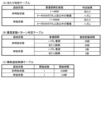
当たり判定は、図9(A)に示すような当たり判定テーブルに従って、当たりか否か(補助遊技を実行するか否か)を決定するための判定である。当たり判定テーブルは、後述する遊技状態に関連付けられている。すなわち、当たり判定テーブルには、非時短状態で用いる当たり判定テーブル(非時短用当たり判定テーブル)と、時短状態で用いる当たり判定テーブル(時短用当たり判定テーブル)と、がある。各当たり判定テーブルでは、当たり判定の結果である当たりとハズレに、普通図柄乱数の判定値(普通図柄乱数値)が振り分けられている。よって、パチンコ遊技機PY1は、取得した普通図柄乱数を当たり判定テーブルに従って判定することにより、当たりかハズレかの当たり判定を行う。そして、当たり判定の結果に基づいて、普図の可変表示を行うための普図変動パターン判定を行う。当たり判定の結果が当たりであると、基本的には、普図の可変表示で当たり図柄が停止表示される。一方、当たり判定の結果がハズレであると、基本的には、普図の可変表示でハズレ普図が停止表示される。なお、当たりの当選確率については、適宜に変更することが可能である。また、当たり判定テーブルを、遊技状態毎に分けなくてもよい。
3-1-1. Win Judgment The win judgment is a judgment for determining whether or not there is a win (whether or not to execute the auxiliary game) according to a hit judgment table as shown in FIG. 9(A). The hit determination table is associated with a gaming state that will be described later. That is, the hit determination table includes a hit determination table used in the non-time-saving state (non-time-saving hit determination table) and a hit determination table used in the time-saving state (time-saving hit determination table). In each hit determination table, determination values of normal symbol random numbers (normal symbol random number values) are assigned to hits and losses that are the results of the hit determination. Therefore, the pachinko game machine PY1 determines whether it is a hit or a loss by determining the acquired normal symbol random number according to the hit determination table. Then, based on the result of the hit determination, a normal pattern variation pattern is determined for variable display of the normal pattern. If the result of the hit determination is a hit, basically the winning symbol is stopped and displayed in the variable display of the common symbol. On the other hand, if the result of the hit determination is a loss, basically the losing common map is stopped and displayed in the variable display of the common symbol. Note that the winning probability can be changed as appropriate. Furthermore, the hit determination table does not need to be divided for each gaming state.
3-1-2.普図変動
普図変動パターン判定は、図9(B)に示すような普図変動パターン判定テーブルに従って、普図変動パターンを決定するための判定である。普図変動パターンとは、普図変動時間などの普図の可変表示に関する所定事項に関する識別情報である。
3-1-2. Ordinary figure fluctuation The ordinary figure fluctuation pattern determination is a determination for determining the ordinary figure fluctuation pattern according to the ordinary figure fluctuation pattern determination table as shown in FIG. 9(B). The ordinary figure fluctuation pattern is identification information regarding predetermined matters related to variable display of ordinary figures, such as ordinary figure fluctuation time.
普図変動パターン判定テーブルは、遊技状態(非時短状態/時短状態)に関連付けられている。すなわち、普図変動パターン判定テーブルには、非時短状態のときに用いられる普図変動パターン判定テーブル(非時短普図変動パターン判定テーブル)と時短状態のときに用いられる普図変動パターン判定テーブル(時短普図変動パターン判定テーブル)とがある。なお、普図変動パターン判定テーブルを遊技状態毎に分けなくてもよい。 The regular figure fluctuation pattern determination table is associated with the gaming state (non-time saving state/time saving state). That is, the regular figure fluctuation pattern determination table includes a regular figure fluctuation pattern determination table (non-time saving regular figure fluctuation pattern determination table) used in the non-time saving state and a regular figure fluctuation pattern determination table (non-time saving regular figure fluctuation pattern determination table) used in the time saving state. There is a short-time regular map fluctuation pattern determination table). It should be noted that it is not necessary to divide the normal pattern fluctuation pattern determination table for each gaming state.
各普図変動パターン判定テーブルには、普図変動パターン判定の結果である普図変動パターンが、停止される普図毎に1つ格納されている。すなわち、パチンコ遊技機PY1は、非時短状態においてと時短状態においてとで、普図変動時間を異ならせることが可能である。例えば、非時短状態においては、ハズレの普図(ハズレ普図)を停止表示する場合の普図の可変表示については普図変動時間が例えば30秒となる普図変動パターンに決定し、当たり図柄を停止表示する場合の普図の可変表示については普図変動時間が例えば30秒となる普図変動パターンに決定する。また、時短状態においては、ハズレ普図を停止表示する場合の普図の可変表示については普図変動時間が例えば5秒となる普図変動パターンに決定し、当たり図柄を停止表示する場合の普図の可変表示については普図変動時間が例えば5秒となる普図変動パターンに決定する。この判定で決定された普図変動パターンに対応付けられた普図変動時間の普図の可変表示が、普図表示器82で行われる。また、これら普図変動時間については、適宜に変更することが可能である。このように、当たり判定、および、普図変動パターン判定が行われることによって、普図表示器82において普図の可変表示が行われる。
Each ordinary figure fluctuation pattern determination table stores one ordinary figure fluctuation pattern, which is the result of ordinary figure fluctuation pattern determination, for each ordinary figure to be stopped. That is, the pachinko game machine PY1 is capable of making the normal pattern fluctuation time different between the non-time saving state and the time saving state. For example, in a non-time-saving state, for the variable display of common symbols when a losing common symbol (losing common symbol) is stopped and displayed, a common symbol fluctuation pattern is determined such that the common symbol fluctuation time is, for example, 30 seconds, and the winning symbol is Regarding the variable display of ordinary figures in the case where the ordinary figures are stopped and displayed, a general figure fluctuation pattern is determined in which the ordinary figure fluctuation time is, for example, 30 seconds. In addition, in the time saving state, for the variable display of common symbols when a losing common symbol is stopped and displayed, a common symbol fluctuation pattern is determined such that the common symbol fluctuation time is, for example, 5 seconds, and when the winning symbol is stopped and displayed, a common symbol fluctuation pattern is determined. Regarding the variable display of figures, a general figure fluctuation pattern is determined in which the ordinary figure fluctuation time is, for example, 5 seconds. A variable display of the ordinary figure of the ordinary figure fluctuation time associated with the ordinary figure fluctuation pattern determined by this determination is performed on the
3-1-3.補助遊技
補助遊技は、普図の可変表示で、表示結果(普図抽選の結果)として、当たり図柄が停止表示(導出)されると実行される。
3-1-3. Auxiliary Game The auxiliary game is a variable display of a common symbol, and is executed when a winning symbol is stopped and displayed (derived) as a display result (result of a common symbol lottery).
補助遊技を構成する要素(補助遊技構成要素)には、電チュー12Dが開放する回数、および各開放についての開放時間などの様々な要素が含まれている。そして、これらの各要素は、遊技状態(非時短状態/時短状態)に対応付けられている。パチンコ遊技機PY1は、遊技状態(非時短状態/時短状態)に基づいて、図9(C)に示すような補助遊技制御テーブルに従って補助遊技を制御する。補助遊技制御テーブルは、遊技状態(非時短状態/時短状態)に対応付けられている。各補助遊技制御テーブルには、補助遊技構成要素が格納されている。なお、これらの各要素における開放回数や開放時間については、適宜に変更することが可能である。
The elements constituting the auxiliary game (auxiliary game component) include various elements such as the number of times the
パチンコ遊技機PY1は、非時短状態における補助遊技と時短状態における補助遊技とで、電チュー12Dの開放時間を異ならせている。例えば、非時短状態における補助遊技では、第1の開放時間(遊技球を電チュー12Dに入賞させるのが困難な時間(例えば0.08秒))だけ電チュー12Dを開放する。以下において、非時短状態における補助遊技のことを「ショート開放補助遊技」ともいう。また、時短状態における補助遊技では、第1の開放時間よりも長い第2の開放時間(遊技球を電チュー12Dに入賞させるのが容易な時間(例えば3.0秒))だけ電チュー12Dを開放する。以下において、時短状態における補助遊技のことを「ロング開放補助遊技」ともいう。なお、非時短状態における補助遊技と時短状態における補助遊技とで、電チュー12Dの開放時間が同じであってもよい。
In the pachinko game machine PY1, the opening time of the
3-2.特図に関わる遊技
次に、特図に関わる遊技について説明する。パチンコ遊技機PY1は、発射された遊技球が第1始動口11に入賞すると、特図1抽選を行う。特図1抽選が行われると、特図1表示器81aにおいて、特図1の可変表示(変動表示を行った後に停止表示)を行って、特図1抽選の結果を報知する。ここで、停止表示される特図1には、大当たり図柄およびハズレ図柄がある。すなわち、特図1抽選の結果には大当たり、およびハズレがある。大当たり図柄が停止表示されると大当たり遊技が実行され、新たな遊技状態が設定されて、当該入賞に基づく遊技が終了する。一方、ハズレ図柄が停止表示されると、大当たり遊技が行われず、当該入賞に基づく遊技が終了する。
3-2. Games Related to Special Figures Next, games related to special figures will be explained. The pachinko game machine PY1 performs a
同様に、パチンコ遊技機PY1は、発射された遊技球が第2始動口12に入賞すると、特図2抽選を行う。特図2抽選が行われると、特図2表示器81bにおいて、特図2の可変表示(変動表示を行った後に停止表示)を行って、特図2抽選の結果を報知する。ここで、停止表示される特図2には、大当たり図柄、およびハズレ図柄がある。すなわち、特図2抽選の結果には、大当たり、およびハズレがある。大当たり図柄が停止表示されると大当たり遊技が実行され、新たな遊技状態が設定されて、当該入賞に基づく遊技が終了する。一方、ハズレ図柄が停止表示されると大当たり遊技が行われず、当該入賞に基づく遊技が終了する。
Similarly, the pachinko game machine PY1 performs a
なお、以下において、第1始動口11に遊技球が入賞することを「第1始動条件の成立」といい、第2始動口12に遊技球が入賞することを「第2始動条件の成立」という。また、「第1始動条件の成立」と「第2始動条件の成立」をまとめて「始動条件の成立」と総称する。また、特別図柄のハズレ図柄については、前述の普図のハズレ図柄と区別するために「ハズレ特図」ともいう。
In addition, below, when a game ball enters the
パチンコ遊技機PY1は、このような一連の遊技(特図抽選、特図の可変表示、大当たり遊技、遊技状態の設定)を行うにあたり、始動条件の成立により、特図関係乱数を取得し、当該乱数について種々の判定を行う。取得する特図関係乱数には、図8(B)に示すように、特別図柄乱数(大当たり乱数)、大当たり図柄種別乱数、リーチ乱数および特図変動パターン乱数がある。特別図柄乱数は大当たり判定を行うための乱数である。大当たり図柄種別乱数は大当たり図柄種別判定を行うための乱数である。リーチ乱数はリーチ判定を行うための乱数である。特図変動パターン乱数は特別図柄の変動パターン判定を行うための乱数である。乱数を判定情報とも言う。各乱数には、適宜に範囲が設けられている。 Pachinko game machine PY1 acquires a special pattern-related random number when a starting condition is established in order to play a series of games (special pattern drawing, variable display of special pattern, jackpot game, and setting of gaming state). Perform various judgments regarding random numbers. As shown in FIG. 8(B), the special pattern related random numbers to be acquired include special pattern random numbers (jackpot random numbers), jackpot pattern type random numbers, reach random numbers, and special pattern fluctuation pattern random numbers. The special symbol random number is a random number for determining a jackpot. The jackpot symbol type random number is a random number for determining the jackpot symbol type. The reach random number is a random number for determining reach. The special symbol variation pattern random number is a random number for determining the variation pattern of the special symbol. Random numbers are also called judgment information. Each random number has an appropriate range.
3-2-1.大当たり判定
大当たり判定は、図10(A)に示すような大当たり判定テーブルに従って、大当たりか否か(大当たり遊技を実行するか否か)を決定するための判定である。大当たり判定テーブルは、遊技状態、詳細には、通常確率状態であるか高確率状態であるかに関連付けられている。すなわち、大当たり判定テーブルには、通常確率状態において用いられる大当たり判定テーブル(通常確率用大当たり判定テーブル)と高確率状態において用いられる大当たり判定テーブル(高確率用大当たり判定テーブル)とがある。
3-2-1. Jackpot Judgment Jackpot Judgment is a judgment for determining whether or not it is a jackpot (whether or not to execute a jackpot game) according to a jackpot judgment table as shown in FIG. 10(A). The jackpot determination table is associated with the gaming state, specifically whether it is a normal probability state or a high probability state. That is, the jackpot determination table includes a jackpot determination table used in the normal probability state (normal probability jackpot determination table) and a jackpot determination table used in the high probability state (high probability jackpot determination table).
各大当たり判定テーブルでは、大当たり判定の結果である大当たり、およびハズレに、特別図柄乱数の判定値(特別図柄乱数値)が振り分けられている。パチンコ遊技機PY1は、取得した特別図柄乱数を大当たり判定テーブルに従って判定することにより、大当たり、またはハズレの何れであるかを判定する。図10(A)に示すように、高確率用大当たり判定テーブルの方が、通常確率用大当たり判定テーブルよりも、大当たりと判定される特別図柄乱数判定値が多く設定されている。また、大当たりの当選確率については、適宜に変更することが可能である。 In each jackpot determination table, special symbol random number determination values (special symbol random number values) are assigned to jackpots and losses that are the results of the jackpot determination. The pachinko game machine PY1 determines whether it is a jackpot or a loss by determining the acquired special symbol random number according to the jackpot determination table. As shown in FIG. 10(A), the high probability jackpot determination table has more special symbol random number determination values that are determined to be a jackpot than the normal probability jackpot determination table. Furthermore, the probability of winning a jackpot can be changed as appropriate.
3-2-2.大当たり図柄種別判定
大当たり図柄種別判定は、大当たり判定の結果が大当たりである場合に、図10(B)に示すような大当たり図柄種別判定テーブルに従って大当たり図柄の種別(大当たり図柄種別)を決定するための判定である。大当たり図柄の種別毎に、大当たりの内容、換言すれば、遊技者に付与される遊技特典などで構成される大当たりの構成要素が対応付けられている。
3-2-2. Jackpot symbol type determination Jackpot symbol type determination is a method for determining the type of jackpot symbol (jackpot symbol type) according to the jackpot symbol type determination table as shown in FIG. 10(B) when the result of jackpot determination is a jackpot. It is a judgment. Each type of jackpot symbol is associated with the content of the jackpot, in other words, the constituent elements of the jackpot consisting of game benefits given to the player.
大当たり図柄種別判定テーブルは、可変表示される特別図柄の種別(特図1/特図2)、言い換えれば、当該大当たり図柄種別判定の起因となる入賞(当該大当たり図柄種別判定を発生させた入賞)が行われた始動口の種別(第1始動口11/第2始動口12)に関連付けられている。すなわち、大当たり図柄種別判定テーブルには、特図1の可変表示を行うときに用いられる大当たり図柄種別判定テーブル(第1大当たり図柄種別判定テーブル)と特図2の可変表示を行うときに用いられる大当たり図柄種別判定テーブル(第2大当たり図柄種別判定テーブル)とがある。
The jackpot symbol type determination table shows the types of special symbols that are variably displayed (Special Figure 1/Special Figure 2), in other words, the prize that causes the jackpot symbol type determination (the prize that causes the jackpot symbol type determination) It is associated with the type of starting port (first starting
大当たり図柄には複数種類の種別があり、各大当たり図柄種別判定テーブルでは、大当たり図柄種別判定の結果である大当たり図柄種別に、大当たり図柄種別乱数の判定値(大当たり図柄種別乱数値)が振り分けられている。よって、パチンコ遊技機PY1は、取得した大当たり図柄種別乱数を大当たり図柄種別判定テーブルに従って判定することにより、大当たり図柄の種別を判定する。そして、第1大当たり図柄種別判定テーブルおよび第2大当たり図柄種別判定テーブルでは、大当たり図柄種別乱数値が各種大当たり図柄に適宜に振り分けられている。なお、大当たり図柄種別の振分率については、適宜に変更することが可能である。また、大当たり図柄の種別については、適宜に増加したり減少したりすることが可能である。 There are multiple types of jackpot symbols, and in each jackpot symbol type determination table, the judgment value of the jackpot symbol type random number (jackpot symbol type random number value) is assigned to the jackpot symbol type that is the result of the jackpot symbol type determination. There is. Therefore, the pachinko gaming machine PY1 determines the type of jackpot symbol by determining the acquired jackpot symbol type random number according to the jackpot symbol type determination table. In the first jackpot symbol type determination table and the second jackpot symbol type determination table, the jackpot symbol type random values are appropriately distributed to various jackpot symbols. Note that the distribution rate of the jackpot symbol type can be changed as appropriate. Furthermore, the types of jackpot symbols can be increased or decreased as appropriate.
例えば、図10(B)に示すように、特図1についての大当たり図柄種別判定による大当たり図柄種別の振分率を、大当たり図柄Aが50%、大当たり図柄Bが50%にし、特図2についての大当たり図柄種別判定による大当たり図柄種別の振分率を、大当たり図柄Cが100%にすることが可能である。このように、第1始動口11に遊技球が入賞して行われる特図1抽選と、第2始動口12に遊技球が入賞して行われる特図2抽選とで、大当たり図柄種別の振分率を異ならせることが可能である。
For example, as shown in FIG. 10(B), the distribution ratio of the jackpot symbol type based on the jackpot symbol type determination for
3-2-3.リーチ判定
リーチ判定は、大当たり判定の結果がハズレである場合に、図10(C)に示すようなリーチ判定テーブルに従って、後述する特図変動演出でリーチを発生させるか否かを決定するための判定である。
3-2-3. Reach Judgment Reach judgment is used to determine whether or not to generate a reach in the special figure variation effect described later, in accordance with the reach judgment table as shown in FIG. 10 (C) when the result of jackpot judgment is a loss. It is a judgment.
リーチ判定テーブルは、遊技状態(非時短状態/時短状態)に関連付けられている。すなわち、リーチ判定テーブルには、非時短状態のときに用いられるリーチ判定テーブル(非時短用リーチ判定テーブル)と時短状態のときに用いられるリーチ判定テーブル(時短用リーチ判定テーブル)とがある。なお、リーチ判定テーブルを遊技状態毎に分けなくてもよい。 The reach determination table is associated with the gaming state (non-time saving state/time saving state). That is, the reach determination table includes a reach determination table used in a non-time saving state (non-time saving reach determination table) and a reach determination table used in a time saving state (time saving reach determination table). Note that the reach determination table does not need to be divided for each gaming state.
各リーチ判定テーブルでは、リーチ判定の結果である「リーチ有り(リーチを発生させる)」と「リーチ無し(リーチを発生させない)」に、リーチ乱数の判定値(リーチ乱数値)が振り分けられている。よって、パチンコ遊技機PY1は、取得したリーチ乱数をリーチ判定テーブルに従って判定することにより、リーチ有りかリーチ無しか(リーチを発生させるか否か)を判定する。図10(C)に示すように、非時短用リーチ判定テーブルと時短用リーチ判定テーブルとで、「リーチ有り(リーチを発生させる)」と判定されるリーチ乱数値の数が異なっている。なお、リーチ有りと判定される確率については、適宜に変更することが可能である。以下において、大当たり判定の結果が「ハズレ」であることを前提に行われる「リーチ有り(リーチを発生させる)」のことを「リーチ有りハズレ」といい、「リーチ無し(リーチを発生させない)」のことを「リーチ無しハズレ」ということもある。 In each reach determination table, the reach random number determination value (reach random value) is assigned to the reach determination results of "reach exists (reach occurs)" and "reach does not occur (reach does not occur)" . Therefore, the pachinko game machine PY1 determines whether there is a reach or not (whether or not to generate a reach) by determining the obtained reach random number according to the reach determination table. As shown in FIG. 10(C), the number of reach random values that are determined as "reach exists (reach occurs)" is different between the non-time-saving reach determination table and the time-saving reach determination table. Note that the probability of determining that there is a reach can be changed as appropriate. In the following, "with reach" (which causes reach), which is performed on the premise that the result of the jackpot determination is "loss", is referred to as "reach with reach", and "without reach (which does not cause reach)". This is sometimes referred to as a "no-reach loss."
3-2-4.特図変動パターン判定
特図変動パターン判定は、図11~図12に示すような特別図柄の変動パターン判定テーブル(特図変動パターン判定テーブル)を用いて、特図の可変表示の変動パターン(特図変動パターン)を決定するための判定であり、大当たり判定の結果が大当たり、およびハズレの何れの場合にも行われる。特図変動パターンとは、特図変動時間や後述する特図変動演出の演出フロー(演出内容)などに関する所定事項を識別するための識別情報である。なお、特図変動パターンには、特図変動時間や特図変動演出の演出フロー(演出内容)の他、大当たり判定の結果とリーチ判定の結果に関する識別情報が含まれている。特図変動パターンに含ませる識別情報は、適宜に変更することが可能である。また、特図変動パターンとして、それぞれ識別情報が異なる複数種類の特図変動パターンを用いることが可能であり、その数は適宜に変更することが可能である。
3-2-4. Special pattern fluctuation pattern determination To determine the special pattern fluctuation pattern, use the special pattern fluctuation pattern determination table (special pattern fluctuation pattern determination table) shown in FIGS. This is a determination to determine the figure fluctuation pattern), and is performed whether the result of the jackpot determination is a jackpot or a loss. The special figure variation pattern is identification information for identifying predetermined matters regarding the special figure variation time and the production flow (production content) of the special figure variation production described later. In addition, the special figure fluctuation pattern includes identification information regarding the result of jackpot determination and the result of reach determination, in addition to the special figure fluctuation time and the production flow (performance content) of the special symbol variation performance. The identification information included in the special figure fluctuation pattern can be changed as appropriate. Further, as the special figure variation pattern, it is possible to use a plurality of types of special figure variation patterns each having different identification information, and the number thereof can be changed as appropriate.
特図変動パターン判定テーブルは、判定対象となる可変表示を行う特別図柄の種別(特図1/特図2)、言い換えれば、当該特図変動パターン判定の起因となる入賞が行われた始動口の種別(第1始動口11/第2始動口12)に関連付けられている。すなわち、特図変動パターン判定テーブルには、特図1の可変表示を行うときに用いられる特図変動パターン判定テーブル(特図1変動パターン判定テーブル:図11)と、特図2の可変表示を行うときに用いられる特図変動パターン判定テーブル(特図2変動パターン判定テーブル:図12)とがある。なお、特図変動パターン判定テーブルを、特別図柄の種別(特図1/特図2)に応じて分けなくてもよい。
The special pattern variation pattern determination table is the type of special symbol that displays a variable display that is subject to judgment (
そして、各特図変動パターン判定テーブルは、遊技状態(非時短状態/時短状態)にも関連付けられている。すなわち、特図1変動パターン判定テーブルには、非時短状態のときに用いられる特図1変動パターン判定テーブル(非時短用特図1変動パターン判定テーブル)と、時短状態のときに用いられる特図1変動パターン判定テーブル(時短用特図1変動パターン判定テーブル)とがある。一方、特図2変動パターン判定テーブルについても同様に、非時短状態のときに用いられる特図2変動パターン判定テーブル(非時短用特図2変動パターン判定テーブル)と、時短状態のときに用いられる特図2変動パターン判定テーブル(時短用特図2変動パターン判定テーブル)とがある。なお、特図変動パターン判定テーブルを、遊技状態毎に分けなくてもよい。 Each special figure fluctuation pattern determination table is also associated with the gaming state (non-time saving state/time saving state). That is, the special figure 1 variation pattern judgment table includes a special figure 1 variation pattern judgment table used in the non-time saving state (special figure 1 variation pattern judgment table for non-time saving), and a special figure 1 variation pattern judgment table used in the time saving state. There is a 1 variation pattern determination table (time saving special figure 1 variation pattern determination table). On the other hand, regarding the special figure 2 variation pattern judgment table, there is also a special figure 2 variation pattern judgment table used in the non-time saving state (special figure 2 variation pattern judgment table for non-time saving) and a special figure 2 variation pattern judgment table used in the time saving state. There is a special figure 2 variation pattern determination table (time-saving special figure 2 variation pattern determination table). Note that the special figure fluctuation pattern determination table does not need to be divided for each gaming state.
また、遊技状態(非時短状態/時短状態)に関連付けられた各特図変動パターン判定テーブルは、さらに、大当たり判定結果およびリーチ判定結果にも関連付けられている。すなわち、非時短用特図1変動パターン判定テーブルおよび非時短用特図2変動パターン判定テーブルにはそれぞれ、大当たり用、リーチ有りハズレ用、およびリーチ無しハズレ用がある。同様に、時短用特図1変動パターン判定テーブルおよび時短用特図2変動パターン判定テーブルにもそれぞれ、大当たり用、リーチ有りハズレ用、およびリーチ無しハズレ用がある。なお、特図変動パターン判定テーブルを、大当たり判定結果やリーチ判定結果に応じて分けなくてもよい。 In addition, each special figure fluctuation pattern determination table associated with the gaming state (non-time saving state/time saving state) is further associated with the jackpot determination result and the reach determination result. That is, the non-time-saving special figure 1 variation pattern determination table and the non-time-saving special figure 2 variation pattern determination table include one for a jackpot, one for a loss with a reach, and one for a loss without a reach. Similarly, the time-saving special figure 1 variation pattern determination table and the time-saving special figure 2 variation pattern determination table each include one for jackpot, one for loss with reach, and one for loss without reach. In addition, it is not necessary to divide the special figure fluctuation pattern determination table according to the jackpot determination result or the reach determination result.
さらに、各リーチ無しハズレ用の特図1変動パターン判定テーブルは、特図保留数にも関連付けられている。例えば、特図1保留数(U1)が0~2のときに用いられるリーチ無しハズレ用の特図1変動パターン判定テーブルと、特図1保留数(U1)が3~4のときに用いられるリーチ無しハズレ用の特図1変動パターン判定テーブルと、がある。また、各リーチ無しハズレ用の特図2変動パターン判定テーブルは、特図保留数にも関連付けられている。具体的には、特図2保留数(U2)が0~2のときに用いられるリーチ無しハズレ用の特図2変動パターン判定テーブルと、特図2保留数(U2)が3~4のときに用いられるリーチ無しハズレ用の特図2変動パターン判定テーブルと、がある。なお、特図変動パターン判定テーブルを、特図保留数に応じて分けなくてもよい。
Furthermore, each special figure 1 fluctuation pattern determination table for no reach loss is also associated with the number of reserved special figures. For example, there is a
そして、各特図変動パターン判定で決定された特図変動パターンに応じた特図変動時間の特図の可変表示が、特図表示器81で行われる。そして、特図の可変表示で、表示結果(特図抽選の結果)として、大当たり図柄が停止表示されると、即座に次の特図の可変表示が行われず、引き続いて、大当たり遊技が実行される。
Then, variable display of the special figure of the special figure fluctuation time according to the special figure fluctuation pattern determined by each special figure fluctuation pattern judgment is performed on the
また、各特図変動パターンには、図11~図12の表の右から2番目の欄に示すような特図変動演出の演出フローが関連付けられている。なお、特図変動パターンに特図変動演出の演出フローを関連付けなくてもよい。 Further, each special figure variation pattern is associated with a production flow of a special figure variation production as shown in the second column from the right in the table of FIGS. 11 and 12. Note that it is not necessary to associate the production flow of the special symbol variation performance with the special symbol variation pattern.
また、図11~図12の表の一番右の欄に示すように、特図変動パターンを、特図(大当たり判定結果)および特図変動演出の演出内容などに関連付けた名称で呼ぶことがある。例えば、大当たりに係る特図変動パターンのことを「大当たり変動」と言う。そして、大当たり変動の中で、リーチの一種であるSPリーチが行われる特図変動パターンのことを「SP大当たり変動」と言い、Lリーチが行われる特図変動パターンのことを「L大当たり変動」と言い、Nリーチで特図変動演出が終わる特図変動パターンのことを「N大当たり変動」と言う。一方、リーチ有りハズレの中で、リーチの一種であるSPリーチが行われる特図変動パターンのことを「SPハズレ変動」と言い、リーチ有りハズレの中で、リーチの一種であるLリーチが行われる特図変動パターンのことを「Lハズレ変動」と言い、リーチ有りハズレの中で、リーチの一種であるNリーチで特図変動演出が終わる特図変動パターンのことを「Nハズレ変動」と言い、リーチ無しハズレに係る特図変動パターンのことを「通常ハズレ変動」と言う。通常ハズレ変動には、変動時間が互いに異なる3種類の変動(通常Aハズレ変動、通常Bハズレ変動、通常Cハズレ変動)がある。また、SP大当たりとSPハズレ変動とを総称する場合、SP変動あるいはSPリーチ変動と言う。 Additionally, as shown in the rightmost column of the tables in Figures 11 and 12, the special pattern fluctuation pattern can be called by a name associated with the special pattern (jackpot determination result) and the production content of the special pattern fluctuation performance. be. For example, a special pattern fluctuation pattern related to a jackpot is called a "jackpot fluctuation." Among the jackpot fluctuations, the special pattern fluctuation pattern in which SP reach, which is a type of reach, is performed is called "SP jackpot fluctuation", and the special pattern fluctuation pattern in which L reach is performed is "L jackpot fluctuation". The special pattern variation pattern in which the special pattern variation performance ends at N reach is called "N jackpot variation". On the other hand, a special symbol fluctuation pattern in which SP reach, which is a type of reach, is performed in a loss with reach is called "SP loss fluctuation", and a L reach, which is a type of reach, is performed in a loss with reach. The special pattern variation pattern that occurs is called "L loss variation", and the special pattern variation pattern in which the special pattern variation effect ends with N reach, which is a type of reach, is called "N loss variation" in a loss with reach. The special pattern fluctuation pattern related to no reach loss is called "normal loss fluctuation". There are three types of normal loss fluctuations (normal A loss fluctuations, normal B loss fluctuations, and normal C loss fluctuations) with different variation times. Moreover, when SP jackpot and SP loss fluctuation are collectively referred to as SP fluctuation or SP reach fluctuation.
3-2-5.先読み判定
パチンコ遊技機PY1は、取得した特図関係乱数に基づいて、図13に示すような先読み判定テーブルに従って先読み判定を行う。先読み判定は、大当たり判定よりも前に(具体的には例えば始動口への入賞時に)行われる。先読み判定には、例えば、特別図柄乱数が大当たり判定で大当たりと判定されるか否かの判定、大当たり図柄種別乱数が大当たり図柄種別判定で何れの大当たり図柄の種別に決定されるかの判定、特図変動パターン乱数が特図変動パターン判定で何れの特図変動パターンに決定されるかの判定、などがある。先読み判定テーブルは、その始動入賞に係る始動口の種別(第1始動口11/第2始動口12)に関連付けられている。すなわち、先読み判定テーブルには、第1始動口11に入賞した場合の先読み判定テーブル(第1先読み判定テーブル)と、第2始動口12に入賞した場合の先読み判定テーブル(第2先読み判定テーブル)と、がある。第1始動口11は特図1の抽選の契機となる始動口であるため、第1先読み判定テーブルを特図1先読み判定テーブルと言うこともできる。また、第2始動口12は特図2の抽選の契機となる始動口であるため、第2先読み判定テーブルを特図2先読み判定テーブルと言うこともできる。なお、先読み判定テーブルを、始動口の種別(第1始動口11/第2始動口12)に応じて分けなくてもよい。
3-2-5. Pre-reading Judgment The pachinko gaming machine PY1 performs pre-reading judgment based on the acquired special figure related random number according to the pre-reading judgment table as shown in FIG. The look-ahead determination is performed before the jackpot determination (specifically, for example, when winning a prize in the starting slot). The look-ahead determination includes, for example, determining whether the special symbol random number is determined to be a jackpot in the jackpot determination, determining which jackpot symbol type the jackpot symbol type random number is determined to be in the jackpot symbol type determination, and determining whether the special symbol random number is determined to be a jackpot in the jackpot symbol type determination. There is a determination as to which special figure variation pattern the figure variation pattern random number is determined to be in the special figure variation pattern determination. The pre-reading determination table is associated with the type of starting opening (first starting
また、先読み判定テーブルは、遊技状態(非時短状態/時短状態)にも関連付けられている。すなわち、先読み判定テーブルには、非時短状態のときに用いられる先読み判定テーブル(非時短用先読み判定テーブル)と、時短状態のときに用いられる先読み判定テーブル(時短用先読み判定テーブル)と、がある。 Further, the pre-reading determination table is also associated with the gaming state (non-time saving state/time saving state). That is, the look-ahead determination table includes a look-ahead decision table used in a non-time-saving state (a look-ahead decision table for non-time savings) and a look-ahead decision table used in a time-saving state (a look-ahead decision table for time savings). .
つまり、先読み判定テーブルには、非時短状態のときに用いられる第1先読み判定テーブルと、時短状態のときに用いられる第1先読み判定テーブルと、非時短状態のときに用いられる第2先読み判定テーブルと、時短状態のときに用いられる第2先読み判定テーブルと、がある。なお、先読み判定テーブルを、遊技状態毎に分けなくてもよい。また、先読み判定にどのような判定を含ませるかは適宜に変更可能である。 In other words, the look-ahead determination table includes a first look-ahead decision table used in the non-time saving state, a first look-ahead decision table used in the time save state, and a second look-ahead decision table used in the non-time save state. and a second look-ahead determination table used in the time saving state. Note that the pre-reading determination table does not need to be divided for each gaming state. Moreover, what kind of determination is included in the prefetch determination can be changed as appropriate.
3-3.大当たり遊技
次に、大当たり遊技について説明する。大当たり遊技は、大入賞口(第1大入賞口14あるいは第2大入賞口15)の開閉を伴う複数回のラウンド遊技と、大当たり遊技が開始してから初回のラウンド遊技が開始されるまでのオープニング(OPとも表記する)と、最終回のラウンド遊技が終了してから大当たり遊技が終了するまでのエンディング(EDとも表記する)とを含んでいる。各ラウンド遊技は、オープニングの終了又は前のラウンド遊技の終了によって開始し、次のラウンド遊技の開始又はエンディングの開始によって終了する。また、OPやEDを設けないようすることが可能である。なお、以下において、所定回数目(所定の順番)のラウンド遊技を、単に「ラウンド」という。例えば、初回(1回目)のラウンド遊技のことを「1ラウンド(1R)」といい、10回目のラウンド遊技のことを「10ラウンド(10R)」という。
3-3. Jackpot Game Next, the jackpot game will be explained. A jackpot game consists of multiple round games involving the opening and closing of the jackpot (
このような大当たり遊技を構成する要素(大当たり遊技構成要素)には、ラウンド遊技の回数、各回のラウンド遊技における大入賞口(第1大入賞口14、第2大入賞口15)の開放回数、各開放が行われる大入賞口の種別および開放時間、次回の開放まで閉鎖させる時間(閉鎖時間あるいはインターバル時間)、オープニングの時間(オープニング時間)、およびエンディングの時間(エンディング時間)などが含まれている。パチンコ遊技機PY1は、特図の停止表示後、図14に示すような大当たり遊技制御テーブルに従って大当たり遊技を制御する。
The elements constituting such a jackpot game (jackpot game constituent elements) include the number of round games, the number of times the big winning opening (first big winning
図14に示すように、大当たり遊技制御テーブルには、大当たり遊技毎(例えば大当たり遊技A~C毎)に大当たり遊技構成要素が格納されている。各大当たり遊技では、1Rから15Rまでは、最大で29.5秒にわたって第1大入賞口14が開放するラウンド遊技、または、最大で0.1秒にわたって第1大入賞口14が開放するラウンド遊技、が行われる。そして、16R(最終ラウンド)では、最大で29.5秒にわたって第2大入賞口15が開放するラウンド遊技、または、最大で0.1秒にわたって第2大入賞口15が開放するラウンド遊技、が行われる。また、各ラウンド遊技では、予め定めた所定個数(例えば10個)の遊技球が大入賞口センサ14a,15aによって検出されると、大入賞口14,15の最大開放時間が経過する前であっても、ラウンド遊技を終了させる。
As shown in FIG. 14, the jackpot game control table stores jackpot game components for each jackpot game (for example, jackpot games A to C). In each jackpot game, from 1R to 15R is a round game in which the first big winning
なお、図14に示す大当たり遊技Aは、当選した大当たり図柄の種別が大当たり図柄A(図10(B)参照)である場合に実行され、大当たり遊技Bは、当選した大当たり図柄の種別が大当たり図柄Bである場合に実行され、大当たり遊技Cは、当選した大当たり図柄の種別が大当たり図柄Cである場合に実行される構成とすることが可能である。 In addition, the jackpot game A shown in FIG. 14 is executed when the type of the winning jackpot symbol is the jackpot symbol A (see FIG. 10(B)), and the jackpot game B is executed when the type of the winning jackpot symbol is the jackpot symbol. B, and the jackpot game C can be executed when the type of the winning jackpot symbol is jackpot symbol C.
また、各大当たり遊技構成要素における回数や時間については、適宜に変更することが可能である。また、大当たり遊技を、第1大入賞口14および第2大入賞口15の両方を用いて行うことも一方だけを用いて行うことも可能である。第1大入賞口14だけを用いる大当たり遊技しか行わない構成、あるいは、第2大入賞口15だけを用いる大当たり遊技しか行わない構成とする場合には、用いない方の大入賞口を備えない構成としてもよい。また、実行可能な大当たり遊技の種類は、複数種類であってもよいし、1種類であってもよい。
Further, the number of times and time for each jackpot game component can be changed as appropriate. Further, the jackpot game can be played using both the first big winning
ここで、特定領域16について詳細に説明する。特定領域16は、振分部材16kによって、入賞不可能な閉状態と、入賞可能な開状態とをとるので、振分部材16kの作動態様は、特定領域16の開閉態様ということができる。以下において、振分部材16kの作動態様のことを「特定領域16の開閉態様」ともいう。また、特定領域16が開状態にあることを「V開放」ともいい、特定領域16が閉状態にあることを「V閉鎖」ともいう。
Here, the
振分部材16kは一定の作動態様で制御される(つまり、特定領域16は一定の開閉態様で制御される)。例えば、第2大入賞口15の開放が開始してから15秒間、振分ソレノイド16sが通電され、振分部材16kが第2状態(図3(B))に制御される。よって、最大で29.5秒にわたって第2大入賞口15が開放するラウンド遊技では、第2大入賞口15の開放時間およびタイミングと、振分部材16kの第2状態に制御されている時間およびタイミングとの関係から、遊技球が特定領域16を通過する(遊技球を特定領域16に進入させる)ことが容易である。一方、最大で0.1秒にわたって第2大入賞口15が開放するラウンド遊技では、第2大入賞口15の開放時間およびタイミングと、振分部材16kの第2状態に制御されている時間およびタイミングとの関係から、遊技球が特定領域16を通過する(遊技球を特定領域16に進入させる)ことはほぼ不可能(困難)である。このように、振分部材16kの一定の作動態様(特定領域16の一定の開閉態様)と、大当たり遊技における第2大入賞口15の開閉態様との組み合わせで、大当たり遊技において遊技球を特定領域16に進入させることの困難性(容易性)を設定することが可能である。なお、振分部材16kの作動態様は適宜に変更可能である。後述する「パチンコ遊技機PY1の特徴部」の説明において別の作動態様を示した場合、パチンコ遊技機PY1ではその作動態様が採用されているものとする。
The
なお、大当たり遊技中に、遊技球の特定領域16への通過(以下、「V通過」ともいう)が容易な第1開放パターン(Vロング開放パターン)でVAT開閉部材15k及び振分部材16kが作動する大当たりを、「Vロング大当たり」といい、遊技球の特定領域16の通過が不可能又は困難な第2開放パターン(Vショート開放パターン)でVAT開閉部材15k及び振分部材16kが作動する大当たりを、「Vショート大当たり」という。
In addition, during the jackpot game, the VAT opening/closing
3-4.遊技状態
次に、遊技状態について説明する。パチンコ遊技機PY1は、図15に示すように、「低確率低ベース遊技状態」、「低確率高ベース遊技状態」、「高確率低ベース遊技状態」、「高確率高ベース遊技状態」および「大当たり遊技状態」の何れかの遊技状態にすることが可能である。なお、「低確率低ベース遊技状態」を「低確低ベース状態」と、「低確率高ベース遊技状態」を「低確高ベース状態」と、「高確率低ベース遊技状態」を「高確低ベース状態」と、「高確率高ベース遊技状態」を「高確高ベース状態」と、それぞれ略称することがある。遊技状態を構成する状態として、大当たり判定において「大当たり」と判定される確率に係る状態と、電チュー12Dの開放の容易性に係る状態とがある。前者としては、通常確率状態と高確率状態とがある。一方、後者としては、非時短状態と時短状態とがある。
3-4. Game State Next, the game state will be explained. As shown in FIG. 15, the pachinko gaming machine PY1 has "low probability low base gaming state", "low probability high base gaming state", "high probability low base gaming state", "high probability high base gaming state", and " It is possible to set the game state to any one of the "jackpot game state". In addition, "low probability low base gaming state" is referred to as "low probability low base state", "low probability high base gaming state" is referred to as "low probability high base state", and "high probability low base gaming state" is referred to as "high probability". The "low base state" and the "high probability high base gaming state" are sometimes abbreviated as the "high probability high base state," respectively. The gaming states include a state related to the probability of being determined to be a "big hit" in the jackpot determination, and a state related to the ease of opening the
通常確率状態は、「低確率低ベース遊技状態」または「低確率高ベース遊技状態」において設定され、大当たり判定で大当たりと判定される確率が通常の確率である状態である。高確率状態は、「高確率低ベース遊技状態」または「高確率高ベース遊技状態」において設定され、大当たり判定で大当たりと判定される確率が通常確率より高い高確率である状態である。従って、高確率状態は通常確率状態よりも遊技者に有利な遊技状態であると言える。パチンコ遊技機PY1で初めて電源投入されたときには通常確率状態が設定される。そして、大当たりに当選することによって通常確率状態から高確率状態に切り替えることが可能になる。例えば、大当たり遊技において遊技球が特定領域16を通過することによって高確率状態に切り替えることが可能である。また、大当たり図柄の種別によって高確率状態に切り替えることも可能である。高確率状態に切り替える契機をV通過とするか、大当たり図柄の種別とするかは、実現したい遊技性に応じて予め定められているものとする。高確率状態では、大当たりに当選することなく所定回数の大当たり判定が行われることや、次回の大当たりに当選することで、高確率状態から通常確率状態に切り替えることが可能である。
The normal probability state is set in the "low probability low base gaming state" or the "low probability high base gaming state", and is a state in which the probability of being determined to be a jackpot in the jackpot determination is the normal probability. The high probability state is set in the "high probability low base gaming state" or the "high probability high base gaming state", and is a state in which the probability of being determined to be a jackpot in the jackpot determination is higher than the normal probability. Therefore, it can be said that the high probability state is a gaming state that is more advantageous to the player than the normal probability state. When the pachinko game machine PY1 is powered on for the first time, a normal probability state is set. Then, by winning the jackpot, it becomes possible to switch from the normal probability state to the high probability state. For example, in a jackpot game, when the game ball passes through the
非時短状態は、「低確率低ベース遊技状態」、「高確率低ベース遊技状態」または「大当たり遊技状態」において設定される。時短状態は、「低確率高ベース遊技状態」または「高確率高ベース遊技状態」において設定され、非時短状態に比べて、1回の補助遊技における電チュー12Dの開放時間が長くなり易い遊技状態である。例えば、時短状態においては、非時短状態における電チュー12Dの開放時間(例えば0.08秒)よりも長い開放時間(例えば3.0秒)となる。また、時短状態では、特図変動時間の短い特図変動パターンが選択されることが非時短状態よりも多くなるように定められた特図変動パターン判定テーブルに従って、特図変動パターン判定が行われる(図11~図12参照)。その結果、時短状態では、特図保留の消化のペースが速くなり、始動口への有効な入賞(特図保留として記憶され得る入賞)が発生しやすくなる。そのため、スムーズな遊技の進行のもとで大当たりを狙うことができる。
The non-time saving state is set in a "low probability low base gaming state", "high probability low base gaming state" or "jackpot gaming state". The time saving state is set in the "low probability high base gaming state" or the "high probability high base gaming state", and is a gaming state in which the opening time of the
また、時短状態は、非時短状態に比べて、普図変動時間が短くなり易くなっている。例えば、時短状態においては、非時短状態において決定される普図変動時間(30秒)よりも短い普図変動時間(5秒)が決定される(図9(B))。よって、時短状態の方が、単位時間当たりにおける普図抽選の実行回数が多い。 Further, in the time saving state, the normal pattern fluctuation time tends to be shorter than in the non-time saving state. For example, in the time saving state, a regular pattern fluctuation time (5 seconds) is determined which is shorter than the regular pattern fluctuation time (30 seconds) determined in the non-time saving state (FIG. 9(B)). Therefore, in the short time state, the number of times the regular lottery is executed per unit time is greater.
また、時短状態は、非時短状態に比べて、当たり判定で当たりと判定され易くなっている。例えば、時短状態では、非時短状態で当たりと判定される確率(例えば6600/65536)よりも高い確率(例えば59936/65536)で当たりと判定される(図9(A))。よって、時短状態の方が、単位時間当たりにおいて当たり判定で当たりと判定される回数が多い。 Also, in the time-saving state, it is easier to be determined to be a hit in the hit determination than in the non-time-saving state. For example, in the time-saving state, a win is determined with a higher probability (for example, 59936/65536) than in the non-time-saving state (for example, 6600/65536) (FIG. 9(A)). Therefore, in the time saving state, the number of times that a hit is determined to be a hit per unit time is greater.
このように時短状態では、非時短状態に比して、単位時間当たりの電チュー12Dの開放時間が長くなり、第2始動口12へ遊技球が頻繁に入賞し易くなる。その結果、発射球数に対する賞球数の割合であるベースが高くなる。そのため、ベースの高い時短状態では、所持する遊技球を大きく減らすことなく大当たり当選を狙うことができる。従って、時短状態は非時短状態よりも遊技者に有利な遊技状態であると言える。
In this way, in the time-saving state, the opening time of the
パチンコ遊技機PY1で初めて電源投入されたときには非時短状態が設定される。そして、例えば、大当たりに当選することによって時短状態が設定可能になる。時短状態では、大当たりに当選することなく所定回数の大当たり判定が行われることや、次回の大当たりに当選することで、時短状態から非時短状態に変更することが可能である。 When the pachinko game machine PY1 is powered on for the first time, a non-time saving state is set. For example, by winning a jackpot, a time saving state can be set. In the time-saving state, it is possible to change from the time-saving state to a non-time-saving state by performing jackpot determination a predetermined number of times without winning a jackpot, or by winning the next jackpot.
なお、時短状態では、非時短状態に比して、当たりに当選し易く、普図変動時間が短くなり易く、且つ、1回の補助遊技における電チュー12Dの開放時間が長くなり易い。つまり、普図に係る遊技について3つの点で、遊技者に有利に設定されている。しかし、この遊技者に有利に設定されている点はこれらの中の一部であってもよい。また、時短状態における特図変動パターン判定テーブルが、非時短状態におけるものよりも、特図変動時間の短い特図変動パターンが選択され易いものでなくてもよい。
In addition, in the time saving state, compared to the non-time saving state, it is easier to win a prize, the normal pattern fluctuation time is more likely to be shortened, and the opening time of the
なお、パチンコ遊技機PY1で初めて電源投入された後の遊技状態は、通常確率状態且つ非時短状態が設定される「低確率低ベース遊技状態」である。この遊技状態を「通常遊技状態」ともいう。なお、「大当たり遊技状態」では、普図抽選(普図に関する当たり判定)は行われるが特図抽選(大当たり判定)は行われないため、大当たり遊技の開始に伴って、非時短状態が設定される。また、遊技状態については、前述した遊技状態の全てを用いることも一部だけを用いることも可能である。また、本明細書で説明している各種の遊技状態については、「第n遊技状態」(nは1以上の整数)の形式で任意に表現できるものとする。 The gaming state of the pachinko gaming machine PY1 after it is powered on for the first time is a "low probability low base gaming state" in which a normal probability state and a non-time saving state are set. This gaming state is also referred to as a "normal gaming state." In addition, in the "jackpot game state", the general drawing lottery (win determination regarding general drawings) is carried out, but the special drawing lottery (jackpot judgment) is not performed, so the non-time saving state is set with the start of the jackpot game. Ru. Furthermore, regarding the gaming states, it is possible to use all or only some of the gaming states described above. Further, the various gaming states described in this specification can be arbitrarily expressed in the form of "nth gaming state" (n is an integer of 1 or more).
4.遊技機による主な演出
次に、パチンコ遊技機PY1により行われる主な演出について、図16~図22を用いて説明する。
4. Main performances performed by the gaming machine Next, the main performances performed by the pachinko gaming machine PY1 will be explained using FIGS. 16 to 22.
4-1.演出モード
最初に、演出モードについて説明する。演出モードは、演出の区分(あるいは、上位概念的な属性)のことである。パチンコ遊技機PY1は、演出モードとして、客待ち演出モード、通常演出モードと、確変演出モード、時短演出モードおよび大当たり演出モードを設定することが可能である。
4-1. Production Mode First, the production mode will be explained. The production mode is a division of production (or a superordinate attribute). The pachinko game machine PY1 can set a customer waiting performance mode, a normal performance mode, a variable probability performance mode, a time-saving performance mode, and a jackpot performance mode as performance modes.
客待ち演出モードは、「低確率低ベース遊技状態」、「低確率高ベース遊技状態」、「高確率低ベース遊技状態」および「高確率高ベース遊技状態」において特図変動演出が行われていないときに設定可能であり、特図変動演出が行われていない待機状態であることを示す演出モードである。客待ち演出モードが設定されているときに客待ち演出が行われる。客待ち演出では、例えば、図16(A―1)に示すように、表示部50aにおいてパチンコ遊技機PY1を紹介する客待ちデモ動画G100が表示される。また、客待ちデモ動画G100が表示されているときに通常ボタン40が操作されると、図16(A―2)に示すように、パチンコ遊技機PY1の演出に関する設定を行うための設定画面G101が表示される。演出に関する設定には、スピーカ52から出力される音の音量設定、表示部50aの輝度設定、実行される演出の頻度設定などがある。
In the customer waiting production mode, special symbol fluctuation production is performed in "low probability low base gaming state", "low probability high base gaming state", "high probability low base gaming state" and "high probability high base gaming state". This is a production mode that can be set when there is no special figure variation production and indicates that it is in a standby state where no special symbol variation production is being performed. A customer waiting performance is performed when a customer waiting performance mode is set. In the customer waiting performance, for example, as shown in FIG. 16 (A-1), a customer waiting demonstration video G100 introducing the pachinko game machine PY1 is displayed on the
通常演出モードは、「低確率低ベース遊技状態」または「高確率低ベース遊技状態」において特図変動演出が行われているときに設定可能であり、非時短状態であることを示す演出モードである。通常演出モードには、例えば、図16(B―1)に示すように、表示部50aにおいて昼間の山の景色を表す背景画像(昼間通常用背景画像G102)が表示される第1通常演出モードと、図16(B―2)に示すように、表示部50aにおいて夕方の山の景色を表す背景画像(夕方通常用背景画像G103)が表示される第2通常演出モードと、図16(B―3)に示すように、表示部50aにおいて夜間の山の景色を表す背景画像(夜間通常用背景画像G104)が表示される第3通常演出モードと、があり、大当たりに当選することなく1回または複数回の特図変動演出が行われることを1つの条件として切り替えられる。さらに、第1~第3通常演出モードのそれぞれには、特図変動演出において、リーチが成立する前の通常前段演出モードと、リーチが成立した後の通常後段演出モードと、がある。通常前段演出モードでは、表示部50aにおいて、昼間通常用背景画像G102、夕方通常用背景画像G103および夜間通常用背景画像G104の何れかが表示されるが、通常後段演出モードでは、リーチの種類に応じた専用の背景画像が表示される。また、「高確率低ベース遊技状態」においてのみ設定される特殊演出モードを設けても良い。
The normal production mode can be set when a special symbol variation production is being performed in the "low probability low base gaming state" or the "high probability low base gaming state", and is a production mode that indicates a non-time saving state. be. The normal presentation mode includes, for example, a first normal presentation mode in which a background image representing a daytime mountain scene (normal daytime background image G102) is displayed on the
確変演出モードは、「高確率高ベース遊技状態」において特図変動演出が行われているときに設定可能な演出モードであり、高確率状態且つ時短状態であることを示す演出モードである。確変演出モードでは、例えば、図16(B―4)に示すように、表示部50aにおいて宇宙を表す背景画像(確変用背景画像G105)が表示される。さらに、確変演出モードには、特図変動演出において、リーチが成立する前の確変前段演出モードと、リーチが成立した後の確変後段演出モードと、がある。確変前段演出モードでは、表示部50aにおいて、確変用背景画像G105が表示されるが、確変後段演出モードでは、リーチの種類に応じた専用の背景画像が表示される。
The probability variable production mode is a production mode that can be set when a special symbol variation production is performed in the "high probability high base game state", and is a production mode that indicates a high probability state and a time saving state. In the probability variation production mode, for example, as shown in FIG. 16 (B-4), a background image representing the universe (probability variation background image G105) is displayed on the
時短演出モードは、「低確率高ベース遊技状態」において特図変動演出が行われているときに設定可能な演出モードであり、通常確率状態且つ時短状態であることを示す演出モードである。時短演出モードでは、例えば、図16(B―5)に示すように、表示部50aにおいて空を表す背景画像(時短用背景画像G106)が表示される。さらに、時短演出モードには、特図変動演出において、リーチが成立する前の時短前段演出モードと、リーチが成立した後の時短後段演出モードと、がある。時短前段演出モードでは、表示部50aにおいて、時短用背景画像G106が表示されるが、時短後段演出モードでは、リーチの種類に応じた専用の背景画像が表示される。
The time-saving performance mode is a performance mode that can be set when the special symbol variation performance is being performed in the "low probability high base game state", and is a performance mode that indicates the normal probability state and the time-saving state. In the time-saving effect mode, for example, as shown in FIG. 16 (B-5), a background image representing the sky (time-saving background image G106) is displayed on the
大当たり演出モードは、「大当たり遊技状態」において大当たり遊技が行われているときに設定可能な演出モードであり、大当たり遊技が行われていることを示す演出モードである。大当たり演出モードでは、例えば、大当たり遊技におけるオープニング中には、図16(C―1)に示すように、表示部50aにおいて、大当たり遊技の開始を示唆するオープニング画像G107や「右打ち」を促す右打ち画像G108が表示される大当たりオープニング演出が行われる。大当たり遊技におけるラウンド中には、図16(C―2)に示すように、表示部50aにおいて、ラウンド数を示すラウンド画像G109や払い出された賞球数を示唆する賞球数画像G110が表示されるラウンド演出が行われる。大当たり遊技におけるエンディング中には、図16(C―3)に示すように、表示部50aにおいて、大当たり遊技後に設定される演出モードを示唆するエンディング画像G111や払い出された総賞球数を示唆する総賞球数画像G112が表示される大当たりエンディング演出が行われる。
The jackpot production mode is a production mode that can be set when a jackpot game is being played in the "jackpot game state", and is a production mode that indicates that a jackpot game is being played. In the jackpot production mode, for example, during the opening of a jackpot game, as shown in FIG. A jackpot opening performance in which the winning image G108 is displayed is performed. During a round in a jackpot game, as shown in FIG. 16 (C-2), a round image G109 indicating the number of rounds and a prize ball number image G110 indicating the number of prize balls paid out are displayed on the
なお、演出モードの種類については、適宜に変更または追加することが可能である。 Note that the types of production modes can be changed or added as appropriate.
4-2.特図変動演出
次に、特図変動演出(単に「変動演出」とも言う)について説明する。パチンコ遊技機PY1は、特図の可変表示が開始されると、特図の可変表示に係る特図変動パターンおよび特図抽選結果(大当たり判定結果、大当たり図柄種別判定結果、リーチ判定結果、および、特図変動パターン判定結果)などに基づいて、特図変動演出を実行する。特図変動演出では、表示部50aにおいて、所定の背景画像に重畳的に、演出図柄の変動表示が行われる。演出図柄の変動表示では、演出図柄が変動した後に停止する。すなわち、特図変動時間、演出図柄の変動表示が行われた後に、当該変動が停止して、演出図柄の停止表示が行われる。そして、演出図柄の停止表示によって特図抽選の結果が報知される。
4-2. Special Figure Variation Effect Next, the special figure variation effect (also simply referred to as "variation effect") will be explained. When the variable display of the special pattern starts, the pachinko gaming machine PY1 displays the special pattern variation pattern related to the variable display of the special pattern and the special pattern lottery result (jackpot determination result, jackpot symbol type determination result, reach determination result, and A special figure variation effect is executed based on the special figure variation pattern determination result). In the special symbol variation performance, a variation display of performance symbols is performed on the
なお、特図変動演出では、演出図柄の変動表示以外に、画像表示装置50、スピーカ52、枠ランプ53、盤ランプ54、可動装置55,56,58、通常ボタン40、特殊ボタン41などの様々な演出装置を用いた他の演出を行うことが可能である。この場合、演出図柄の停止表示後も、他の演出を継続して行うことが可能である。
In addition, in the special figure variation production, in addition to the variable display of production symbols, various displays such as the
4-2-1.演出図柄表示領域
画像表示装置50の表示部50aには、図17(A)に示すように、表示部50aを水平方向に3つに略均等に分けた左側、中央および右側それぞれに、左演出図柄領域50b1、中演出図柄領域50b2、および右演出図柄領域50b3を設けることが可能である。左演出図柄領域50b1は、特図変動演出における演出図柄の停止表示のときに、左演出図柄EZ1を表示する領域である。同様に、中演出図柄領域50b2および右演出図柄領域50b3は、中演出図柄EZ2および右演出図柄EZ3を表示する領域である。
4-2-1. Effect pattern display area As shown in FIG. 17(A), the
また、図17(A)に示すように、表示部50aの上端部の左端(左上隅)の一区画に、小図柄領域50cを設けることが可能である。小図柄領域50cは、特図の可変表示が行われているときに小図柄KZ1,KZ2,KZ3を変動表示する領域である。
Moreover, as shown in FIG. 17(A), it is possible to provide a small pattern area 50c in a section of the left end (upper left corner) of the upper end of the
なお、図17(A)において、左演出図柄領域50b1、中演出図柄領域50b2、右演出図柄領域50b3、および小図柄領域50cは二点鎖線で明示されているが、これは左演出図柄領域50b1、中演出図柄領域50b2、右演出図柄領域50b3、および小図柄領域50cの範囲を表すために記載したものであり、実際には表示されていない。また、各領域の範囲は適宜に変更可能である。 In addition, in FIG. 17(A), the left presentation pattern area 50b1, the middle presentation pattern area 50b2, the right presentation pattern area 50b3, and the small pattern area 50c are clearly indicated by two-dot chain lines, but this is the left presentation pattern area 50b1. , the middle effect pattern area 50b2, the right effect pattern area 50b3, and the small pattern area 50c are described to represent the range, and are not actually displayed. Further, the range of each area can be changed as appropriate.
4-2-2.通常変動
パチンコ遊技機PY1は、特図変動演出において、先ず通常変動を行うことが可能である。通常変動は、特図の可変表示が開始されたことを示唆する演出として機能する。
4-2-2. Normal variation Pachinko gaming machine PY1 can first perform normal variation in the special figure variation performance. The normal variation functions as an effect that suggests that the variable display of the special figure has started.
特図の可変表示が開始されると、例えば、図17(A)に示すように、表示部50aにおいて、左演出図柄EZ1、中演出図柄EZ2および右演出図柄EZ3が停止表示されていると共に、左小図柄KZ1、中小図柄KZ2および右小図柄KZ3が停止表示されており、特図の可変表示が行われておらず、特図の可変表示を待機している状態から、図17(B)に示すように、その開始に伴って演出図柄EZ1,EZ2,EZ3の変動表示が開始されると共に、小図柄KZ1,KZ2,KZ3の変動表示が開始される。そして、この特図の可変表示の特図変動パターンが、例えば「通常ハズレ変動」の場合には、図17(C―1)に示すように、左演出図柄EZ1と右演出図柄EZ3とが異なる停止態様で仮停止してから、図17(D)に示すように、ハズレを示唆する停止態様(所謂バラケ目)で演出図柄EZ1,EZ2,EZ3が停止表示する。このとき、小図柄KZ1,KZ2,KZ3もハズレを示唆する停止態様で一斉に停止表示する。一方、特図の可変表示の特図変動パターンが、例えば「Nハズレ変動」などのリーチ有りの特図変動パターンの場合には、図17(C―2)に示すように、左演出図柄EZ1と右演出図柄EZ3とが同じ停止態様で仮停止して、リーチが成立する。このとき、小図柄KZ1,KZ2,KZ3の変動表示は継続して行われ、特図変動パターンに応じたリーチ演出が行われる。なお、演出図柄EZ1,EZ2,EZ3の停止順序や停止態様は、適宜に変更することが可能である。
When the variable display of the special symbols starts, for example, as shown in FIG. 17(A), the left effect pattern EZ1, the middle effect pattern EZ2, and the right effect pattern EZ3 are stopped and displayed on the
4-2-3.Nリーチ
パチンコ遊技機PY1は、通常変動においてリーチが成立するとNリーチを行うことが可能である。Nリーチは、大当たり判定の結果が「大当たり」であった可能性があることを示唆する演出であり、遊技者に大当たりを期待させるための演出として機能する。
4-2-3. N-Reach Pachinko gaming machine PY1 is capable of performing N-Reach when a reach is established in the normal variation. N reach is a performance that suggests that the result of the jackpot determination may be a "jackpot", and functions as a performance to make the player expect a jackpot.
Nリーチでは、図18(A)に示すように、リーチが成立した状態が所定時間(例えば、10秒)維持され、図18(B)に示すように、中演出図柄EZ2の変動速度が徐々に減速していく。そして、特図の可変表示の特図変動パターンが、例えば「Nハズレ変動」の場合には、図18(C―1)に示すように、ハズレを示唆する停止態様(所謂バラケ目)で演出図柄EZ1,EZ2,EZ3が停止表示する。このとき、小図柄KZ1,KZ2,KZ3もハズレを示唆する停止態様で一斉に停止表示する。一方、特図の可変表示の特図変動パターンが、例えば「N大当たり変動」の場合には、図18(C-2)に示すように、大当たりを示唆する停止態様(所謂ゾロ目)で停止表示する。このとき、小図柄KZ1,KZ2,KZ3も大当たりを示唆する停止態様で一斉に停止表示する。なお、Nリーチの演出内容は、中演出図柄EZ2が徐々に減速することに限られず、適宜に変更または追加することが可能である。 In N reach, as shown in FIG. 18(A), the state in which reach is established is maintained for a predetermined period of time (for example, 10 seconds), and as shown in FIG. 18(B), the fluctuation speed of the medium effect pattern EZ2 gradually changes. It slows down. If the special symbol variation pattern of the variable display of the special symbol is, for example, "N loss variation", as shown in FIG. Symbols EZ1, EZ2, and EZ3 are stopped and displayed. At this time, the small symbols KZ1, KZ2, and KZ3 are also stopped and displayed all at once in a stopping manner that suggests a loss. On the other hand, if the special pattern variation pattern of the variable display of the special pattern is, for example, "N jackpot variation", the game will stop in a stopping manner (so-called double) that suggests a jackpot, as shown in Figure 18 (C-2). indicate. At this time, the small symbols KZ1, KZ2, and KZ3 are also stopped and displayed all at once in a stopping manner that suggests a jackpot. Note that the content of the N-reach performance is not limited to the gradual deceleration of the medium performance symbol EZ2, but can be changed or added as appropriate.
また、ハズレを示唆する演出図柄EZ1,EZ2,EZ3の停止態様に関して、リーチが成立しない場合のバラケ目を「非リーチバラケ目」や「非リーチハズレ目」と称し、リーチが成立する場合のバラケ目を「リーチバラケ目」や「リーチハズレ目」と称する。非リーチバラケ目を構成する各演出図柄EZ1,EZ2,EZ3の組み合わせをどのようにするか(例えば「2・3・1」や「5・8・6」等)、および、リーチバラケ目を構成する各演出図柄EZ1,EZ2,EZ3の組み合わせをどのようにするか(例えば「2・1・2」や「5・4・5」等)は、演出制御用マイコン121によって選択される。また、大当たりを示唆する停止態様(ゾロ目)を構成する各演出図柄EZ1,EZ2,EZ3の組み合わせをどのようにするか(例えば「2・2・2」や「7・7・7」等)は、当選した大当たり図柄の種別に基づいて、演出制御用マイコン121によって選択される。
In addition, regarding the stopping patterns of the production patterns EZ1, EZ2, and EZ3 that suggest a loss, the winning pattern when a reach is not established is referred to as a "non-reach winning pattern" or "non-reach losing pattern," and the winning pattern when a reach is achieved is called a ``non-reaching pattern''. They are called "Reach Barake" or "Reach Loss". How to combine the production symbols EZ1, EZ2, and EZ3 that make up the non-reachable numbers (for example, "2, 3, 1" or "5, 8, 6", etc.), and the The
4-2-4.SPリーチ
パチンコ遊技機PY1は、Nリーチの後にSPリーチを行うことが可能である。SPリーチは、大当たり判定の結果が「大当たり」であった可能性が、Nリーチよりも高いことを示唆する演出であり、遊技者に大当たりを期待させるための演出として機能する。
4-2-4. SP Reach Pachinko gaming machine PY1 can perform SP Reach after N Reach. The SP reach is a performance that suggests that the possibility that the result of the jackpot determination is a "big win" is higher than the N reach, and functions as a performance to make the player expect a jackpot.
SPリーチでは、Nリーチの後に、例えば、図19(A)に示すように、表示部50aにSPリーチ専用の背景画像(SPリーチ用背景画像G113)が表示され、表示部50aの中央にSPリーチが開始されたことを表す画像(SPリーチ開始タイトル画像)G1が表示される。その後、図19(B)に示すように、SPリーチ専用演出(例えばバトル演出)が行われる。そして、SPリーチ専用演出の最終局面を迎えると、特図の可変表示の特図変動パターンが、例えば「SP大当たり変動」の場合には、図19(C―1)に示すように、表示部50aに、大当たりを示唆する演出(例えば、主人公キャラクタ(味方キャラクタの一人)がバトルに勝利して仁王立ちしている表示)が行われるとともに、演出図柄EZ1,EZ2,EZ3が大当たりを示唆する停止態様(所謂ゾロ目)で停止表示する。このとき、小図柄KZ1,KZ2,KZ3も大当たりを示唆する停止態様で一斉に停止表示する。一方、特図の可変表示の特図変動パターンが、例えば「SPハズレ変動」の場合には、図19(C―2)に示すように、ハズレを示唆する演出(例えば、敵キャラクタがバトルに勝利して仁王立ちしている表示)が行われるとともに、演出図柄EZ1,EZ2,EZ3がハズレを示唆する停止態様(所謂バラケ目)で停止表示する。このとき、小図柄KZ1,KZ2,KZ3もハズレを示唆する停止態様で一斉に停止表示する。なお、SPリーチの演出内容は、適宜に変更または追加することが可能である。 In SP reach, after N reach, for example, as shown in FIG. An image (SP reach start title image) G1 representing that reach has started is displayed. After that, as shown in FIG. 19(B), an SP reach-only performance (for example, a battle performance) is performed. Then, when the final phase of the SP reach-only performance is reached, if the special pattern fluctuation pattern of the variable display of the special symbol is, for example, "SP jackpot fluctuation", the display part will be displayed as shown in FIG. At 50a, a production that suggests a jackpot is performed (for example, a display in which the main character (one of the ally characters) wins the battle and stands proud), and the production patterns EZ1, EZ2, and EZ3 are stopped to suggest a jackpot. (so-called double eye) is stopped and displayed. At this time, the small symbols KZ1, KZ2, and KZ3 are also stopped and displayed all at once in a stopping manner that suggests a jackpot. On the other hand, if the special pattern variation pattern of the variable display of the special pattern is, for example, "SP loss variation", as shown in FIG. At the same time, the performance symbols EZ1, EZ2, and EZ3 are stopped and displayed in a stopped manner (so-called "break-up") indicating a loss. At this time, the small symbols KZ1, KZ2, and KZ3 are also stopped and displayed all at once in a stopping manner that suggests a loss. Note that the contents of the SP reach performance can be changed or added as appropriate.
ここで、各リーチに対する演出図柄EZ1,EZ2,EZ3が大当たりを示す態様で停止される可能性(大当たり期待度)について詳細に説明する。各リーチに対する大当たり期待度は、大当たり判定の結果に基づく実行確率によって定められる。例えば、Nリーチの実行確率を、大当たり判定の結果が「ハズレ」の場合には10%とし、大当たり判定の結果が「大当たり」の場合には100%として、SPリーチの実行確率を、大当たり判定の結果が「ハズレ」の場合には4%とし、大当たり判定の結果が「大当たり」の場合には100%とすれば、SPリーチの大当たり期待度を、Nリーチの大当たり期待度よりも高く設定することが可能である。また、SPリーチとしてSPリーチAとSPリーチBとを実行可能にし、SPリーチAの実行確率を、大当たり判定の結果が「ハズレ」の場合には2%とし、大当たり判定の結果が「大当たり」の場合には30%として、SPリーチBの実行確率を、大当たり判定の結果が「ハズレ」の場合には2%とし、大当たり判定の結果が「大当たり」の場合には20%とすれば、SPリーチAの大当たり期待度を、SPリーチBの大当たり期待度よりも高く設定することが可能である。このように、大当たり判定の結果に応じた実行確率を適宜に設定することで、大当たり期待度を設定することが可能である。 Here, the possibility that the performance symbols EZ1, EZ2, and EZ3 for each reach will be stopped in a manner indicating a jackpot (jackpot expectation level) will be explained in detail. The jackpot expectation level for each reach is determined by the execution probability based on the jackpot determination result. For example, the execution probability of N Reach is 10% when the jackpot determination result is "Lose", and the execution probability of SP Reach is 100% when the jackpot determination result is "Jackpot", and the execution probability of SP Reach is set as 10% when the jackpot determination result is "Lose". If the result of jackpot judgment is "Lose", it is set to 4%, and if the result of jackpot determination is "Jackpot", it is set to 100%, then the jackpot expectation level of SP reach is set higher than the jackpot expectation level of N reach. It is possible to do so. In addition, SP Reach A and SP Reach B are made executable as SP Reach, and the execution probability of SP Reach A is set to 2% if the result of the jackpot determination is "Lose", and if the result of the Jackpot determination is "Lose", the execution probability of SP Reach A is set to 2%. If the execution probability of SP Reach B is 2% if the result of the jackpot determination is "Lose", and 20% if the result of the jackpot determination is "Jackpot", then It is possible to set the jackpot expectation level of SP Reach A higher than the jackpot expectation level of SP Reach B. In this way, by appropriately setting the execution probability according to the result of the jackpot determination, it is possible to set the jackpot expectation level.
4-2-5.Lリーチ
パチンコ遊技機PY1は、Nリーチの後にLリーチを行うことが可能である。Lリーチは、特図抽選の抽選結果が「大当たり」であった可能性が、SPリーチよりは低いがNリーチよりも高いことを示唆する演出であり、遊技者に大当たりを期待させるための演出として機能する。なお、Lリーチのリーチ演出の実行時間は、SPリーチのリーチ演出の演出時間よりも短い(図11および図12)。よって、Lリーチのリーチ演出では、例えば、SPリーチのリーチ演出よりも短い動画が表示部50aに表示される。なお、Lリーチのリーチ演出の内容は適宜変更可能である。また、Lリーチのリーチ演出の後にSPリーチのリーチ演出が発展的に実行される特図変動パターンを設けてもよい。
4-2-5. L Reach Pachinko gaming machine PY1 can perform L Reach after N Reach. L reach is a production that suggests that the probability that the lottery result of the special drawing lottery is a "big hit" is lower than SP reach, but higher than N reach, and is a production that makes players expect a jackpot. functions as Note that the execution time of the L reach effect is shorter than the execution time of the SP reach effect (FIGS. 11 and 12). Therefore, in the reach effect of L reach, for example, a shorter video than the reach effect of SP reach is displayed on the
4-3.保留アイコン表示領域
画像表示装置50の表示部50aには、図20(A)に示すように、4つの表示領域からなる保留アイコン表示領域50dを設けることが可能である。保留アイコン表示領域50dは、第1表示領域50d1、第2表示領域50d2、第3表示領域50d3および第4表示領域50d4で構成され、特図1保留数または特図2保留数に応じて、各表示領域50d1,50d2,50d3,50d4に、保留アイコンHAを表示することが可能である。例えば、特図1保留数が『1』の場合には、第1表示領域50d1に保留アイコンHAが表示され、特図1保留数が『2』の場合には、第1表示領域50d1と第2表示領域50d2とに保留アイコンHAが表示される。
4-3. Pending Icon Display Area The
また、保留アイコン表示領域50dの近傍に、図20(A)に示すように、1つの表示領域からなる当該アイコン表示領域50eを設けることが可能である。当該アイコン表示領域50eは、特図変動演出が開始されることに応じて、保留アイコンHAと同じ当該アイコンTA(当該保留アイコンTAとも言う)を表示することが可能である。なお、当該アイコンTAとして、保留アイコンHAと異なるアイコンを表示することがあってもよい。
Further, as shown in FIG. 20(A), an
なお、保留アイコン表示領域50dを構成する表示領域の数については、適宜に変更することが可能である。また、保留アイコン表示領域50dを、特図1保留数および特図2保留数の両方を表示する表示領域とすることも一方だけを表示する表示領域とすることも可能である。また、保留アイコン表示領域50dを設けるが当該アイコン表示領域50eを設けない構成としたり、両者を設けない構成としたりすることも可能である。
Note that the number of display areas constituting the pending
4-3-1.保留演出
パチンコ遊技機PY1は、遊技球が第1始動口11または第2始動口12に入賞することに応じて、保留演出を行うことが可能である。保留演出は、特図1保留または特図2保留の数を遊技者に報知することが可能である。
4-3-1. Hold Performance Pachinko gaming machine PY1 can perform hold performance in response to a game ball entering the
保留演出では、特図1保留数が『0』のときに遊技球が第1始動口11に入賞すると、特図変動演出が開始され、例えば、図20(B)に示すように、当該アイコン表示領域50eに当該アイコンTAが表示される。そして、特図変動演出中に更に2個の遊技球が第1始動口11に入賞すると、図20(C)に示すように、保留アイコン表示領域50dの第1表示領域50d1と第2表示領域50d2とに保留アイコンHAが表示され、特図1保留数が『2』であることが遊技者に報知される。その後、特図変動演出が終了し、新たな特図変動演出が開始されると、図20(D)に示すように、保留アイコン表示領域50dの第1表示領域50d1に表示されていた保留アイコンHAが、当該アイコン表示領域50eに移動して当該アイコンTAとして表示され、保留アイコン表示領域50dの第2表示領域50d2に表示されていた保留アイコンHAが、第1表示領域50d1に移動して表示され、特図1保留数が『1』であることが遊技者に報知される。
In the hold effect, when the game ball enters the
4-4.予告演出
パチンコ遊技機PY1は、特図変動演出中の任意のタイミングで予告演出を行うことが可能である。予告演出は、画像表示装置50、スピーカ52、枠ランプ53、盤ランプ54、可動装置55,56,58、入力装置(通常ボタン40、特殊ボタン41)等を用いた演出であり、大当たり判定の結果や特図変動パターン判定の結果を示唆することが可能である。
4-4. Preview Performance The pachinko game machine PY1 can perform a preview performance at any timing during the special figure variation performance. The preview performance is a performance using the
4-4-1.可動体演出
パチンコ遊技機PY1は、予告演出として、可動装置55,56,58を用いた可動体演出を行うことが可能である。可動体演出は、可動装置55,56,58を作動させる演出であり、遊技者に大当たりを期待させるための演出として機能する。
4-4-1. Movable Body Performance The pachinko game machine PY1 is capable of performing a movable body performance using the
可動体演出では、例えば、NリーチからSPリーチに発展する際に、図21(A)に示すように、盤上可動装置55および盤下可動装置56が作動し、盤上可動体55kと盤下可動体56kとが、表示部50a上に重なるように移動して、SPリーチに発展することが示唆される。このとき、表示部50aの盤上可動体55kおよび盤下可動体56kと重なっていないスペースにはエフェクト画像が表示される。その後、図21(B)に示すように、盤上可動体55kと盤下可動体56kとが、通常の待機状態(初期位置)に戻ってSPリーチに発展する。この可動体演出は、発展演出の一例である。なお、可動体演出については、SPリーチへの発展示唆に限られず、適宜に変更または追加することが可能である。また、可動体演出における可動装置の作動内容は、適宜に変更または追加することが可能である。また、可動体演出において作動させる可動装置は、適宜変更可能である。また、演出が発展しない場合(例えばNハズレ変動の場合)に、所謂ガセ演出として、可動体演出を行うようにすることも可能である。可動体演出を、可動体駆動演出とも言う。
In the movable object performance, for example, when N reach progresses to SP reach, as shown in FIG. It is suggested that the lower
4-4-2.操作演出
パチンコ遊技機PY1は、予告演出として、通常ボタン40や特殊ボタン41を用いた操作演出を行うことが可能である。操作演出は、遊技者に通常ボタン40や特殊ボタン41を操作させる演出であり、遊技者に大当たりを期待させるための演出として機能する。
4-4-2. Operation performance The pachinko game machine PY1 can perform an operation performance using the
操作演出では、例えば、SPリーチにおいて、入力装置(特殊ボタン41)の押下操作が有効な期間(操作有効期間)が発生し、この操作有効期間の発生に伴って、図22(A)に示すように、特殊ボタン41の操作を促す演出(操作促進演出)が行われる。操作促進演出において、表示部50aに、操作促進画像G3が表示される。操作促進画像G3は、特殊ボタン41を模した画像(特殊ボタン画像G31)と、特殊ボタン41の操作態様(すなわち、押下操作)を表す画像(押下操作画像G32)と、操作有効期間の残り時間を表す画像(操作有効期間残り時間画像G33)と、を含む。なお、操作有効期間残り時間画像G33は、おおむね曲線状のプログレスバーからなり、時間の経過に伴って、遊技者が操作有効期間の残り時間を容易に理解できるように変化する。その後、操作有効期間において特殊ボタン41が押下操作されることに応じて、または、操作有効期間において特殊ボタン41が操作されることなく操作有効期間が経過した後、図22(B)に示すように、盤上可動装置55が作動し、盤上可動体55kが表示部50a上に重なるように移動して、大当たり期待度が示唆される。なお、操作演出については、盤上可動装置55の作動に限られず、適宜に変更または追加することが可能である。また、特殊ボタン41や通常ボタン40といった操作手段(操作部)の操作を促す操作促進演出を、操作指示演出とも言う。通常ボタン40の操作を促す操作促進演出では、通常ボタン40を模した画像(特殊ボタン画像)、通常ボタン40の操作態様を表す画像、及び、操作有効期間を表す画像を含む操作促進画像が表示部50aに表示される。
In the operation performance, for example, in SP reach, a period (operation valid period) occurs during which the pressing operation of the input device (special button 41) is valid, and with the occurrence of this operation valid period, the period shown in FIG. 22 (A) An effect (operation promotion effect) is performed to prompt the user to operate the
4-4-3.先読み演出
パチンコ遊技機PY1は、予告演出として、特図抽選が行われていない特図1保留または特図2保留に対する先読み演出を行うことが可能である。先読み演出は、特図1保留または特図2保留に対する特図抽選の抽選結果を事前に示唆するための演出として機能する。
4-4-3. Pre-read performance The pachinko gaming machine PY1 is capable of performing a pre-read performance for the special figure 1 hold or the special figure 2 hold for which the special figure lottery has not been performed, as a preview effect. The pre-reading performance functions as a performance for suggesting in advance the lottery result of the special symbol lottery for the
先読み演出では、例えば、特図1保留に対する先読み判定の結果が「大当たり」の場合、図20(C)に示すように、保留アイコン表示領域50dに通常は「〇」で表示される保留アイコンHAを「☆」で表示することがある。また、先読み判定の結果が「ハズレ」の場合に、所謂ガセ演出として、保留アイコンHAを「☆」で表示することがある。このように、保留アイコンHAや当該アイコンTAを通常態様(本形態では「〇」)ではなく特殊態様(本形態では「☆」)で表示する先読み演出を、保留変化演出と言う。また、保留アイコンHAや当該アイコンTAを総称して、保留表示と言う。本形態では、保留表示として、保留アイコンHAと当該アイコンTAとを表示するが、保留アイコンHAだけを表示し当該アイコンTAを表示しない構成としてもよい。また、保留変化演出において特殊態様の保留表示を行うタイミングは、その保留表示の契機となる始動入賞の発生時であってもよいし、その保留表示のシフト表示時(保留アイコンHAの表示領域を変更したとき)であってもよいし、その保留表示に対応する特図変動の実行中(当該アイコンTAとして表示しているとき)であってもよい。また、保留表示の特殊態様には複数の種類があってもよい。
In the look-ahead performance, for example, if the result of the look-ahead determination for the
なお、先読み演出は、特図1保留および特図2保留の両方または一方に対して行うことが可能である。また、先読み演出は、保留アイコンHAの表示態様の変化に限られず、適宜に変更または追加することが可能である。保留変化演出以外の先読み演出としては、例えば、所謂連続予告などが挙げられる。 In addition, the pre-reading performance can be performed for both or one of the special figure 1 reservation and the special figure 2 reservation. Moreover, the prefetch effect is not limited to changing the display mode of the hold icon HA, but can be changed or added as appropriate. An example of a look-ahead performance other than the pending change performance is a so-called continuous notice.
5.遊技制御用マイコン101による遊技の制御
次に図23~図24に基づいて遊技制御用マイコン101による遊技の制御について説明する。なお、以下において説明する遊技制御用マイコン101による遊技の制御において登場するカウンタ、タイマ、バッファ等は、遊技用RAM104に設けられている。
5. Control of the game by the
[1.主制御メイン処理]
主制御基板100に備えられた遊技制御用マイコン101は、パチンコ遊技機PY1が電源投入されると、遊技用ROM103から図23に示した主制御メイン処理のプログラムを読み出して実行する。同図に示すように、主制御メイン処理では、まず、電源投入時処理(S001)を行う。電源投入時処理では、遊技用RAM104へのアクセスの許可設定、遊技用CPU102の設定、SIO、PIO、CTC(割り込み時間の管理のための回路)の設定等が行われる。
[1. Main control main processing]
When the pachinko game machine PY1 is powered on, the
電源投入時処理に次いで、割り込みを禁止し(S002)、普通図柄・特別図柄主要乱数更新処理(S003)を実行する。この普通図柄・特別図柄主要乱数更新処理(S003)では、図8(A)および図8(B)に示した種々の乱数のカウンタ値を1加算して更新する。各乱数のカウンタ値は上限値に達すると「0」に戻って再び加算される。なお各乱数のカウンタの初期値は「0」以外の値であってもよく、ランダムに変更されるものであってもよい。また各乱数のうちの少なくとも一部は、カウンタIC等からなる公知の乱数生成回路を利用して生成される所謂ハードウェア乱数であってもよい。 Following the power-on processing, interrupts are prohibited (S002), and normal symbol/special symbol main random number update processing (S003) is executed. In this normal symbol/special symbol main random number update process (S003), the counter values of the various random numbers shown in FIGS. 8(A) and 8(B) are updated by adding 1. When the counter value of each random number reaches the upper limit value, it returns to "0" and is added again. Note that the initial value of each random number counter may be a value other than "0" or may be changed randomly. Further, at least a portion of each random number may be a so-called hardware random number generated using a known random number generation circuit including a counter IC or the like.
普通図柄・特別図柄主要乱数更新処理(S003)が終了すると、割り込みを許可する(S004)。割り込み許可中は、メイン側タイマ割り込み処理(S005)の実行が可能となる。メイン側タイマ割り込み処理(S005)は、例えば4msec周期で遊技用CPU102に繰り返し入力される割り込みパルスに基づいて実行される。すなわち、メイン側タイマ割り込み処理(S005)は4msec周期で実行される。そして、メイン側タイマ割り込み処理(S005)が終了してから、次にメイン側タイマ割り込み処理(S005)が開始されるまでの間に、普通図柄・特別図柄主要乱数更新処理(S003)による種々の乱数のカウンタ値の更新処理が繰り返し実行される。なお、割り込み禁止状態のときに遊技用CPU102に割り込みパルスが入力された場合は、メイン側タイマ割り込み処理(S005)はすぐには開始されず、割り込み許可(S004)がされてから開始される。
When the normal symbol/special symbol main random number update process (S003) is completed, an interrupt is permitted (S004). While interrupts are enabled, main side timer interrupt processing (S005) can be executed. The main side timer interrupt process (S005) is executed based on an interrupt pulse that is repeatedly input to the
[2.メイン側タイマ割り込み処理]
次に、メイン側タイマ割り込み処理(S005)について説明する。図24に示すように、メイン側タイマ割り込み処理(S005)では、まず出力処理(S101)を実行する。出力処理(S101)では、以下に説明する各処理において主制御基板100の遊技用RAM104に設けられた出力バッファにセットされたコマンド等を、サブ制御基板120や払出制御基板170等に出力する。
[2. Main side timer interrupt processing]
Next, the main side timer interrupt processing (S005) will be explained. As shown in FIG. 24, in the main side timer interrupt processing (S005), output processing (S101) is first executed. In the output process (S101), commands etc. set in the output buffer provided in the
出力処理(S101)に次いで行われる入力処理(S102)では、遊技制御用マイコン101は、例えば、下皿35の満杯を検出する下皿満杯スイッチからの検出信号を取り込み、下皿満杯データとして遊技用RAM104の出力バッファに記憶する。
In the input process (S102) that is performed after the output process (S101), the
次に行われる普通図柄・特別図柄主要乱数更新処理(S103)は、図23の主制御メイン処理で行う普通図柄・特別図柄主要乱数更新処理(S003)と同じである。即ち、図8(A)および図8(B)に示した各種乱数のカウンタ値の更新処理は、メイン側タイマ割り込み処理(S005)の実行期間と、それ以外の期間(メイン側タイマ割り込み処理(S005)の終了後、次のメイン側タイマ割り込み処理(S005)が開始されるまでの期間)との両方で行われている。 The normal symbol/special symbol main random number update process (S103) performed next is the same as the normal symbol/special symbol main random number update process (S003) performed in the main control main process of FIG. That is, the updating process of the counter values of various random numbers shown in FIGS. 8(A) and 8(B) is performed during the execution period of the main side timer interrupt process (S005) and during the other period (main side timer interrupt process (S005)). After the completion of S005), the interrupt processing is performed both during the period until the next main-side timer interrupt processing (S005) is started.
普通図柄・特別図柄主要乱数更新処理(S103)に次いで、遊技制御用マイコン101は、センサ検出処理(S104)を行い、続いて普通動作処理(S105)を行い、さらに特別動作処理(S106)を行う。センサ検出処理、普通動作処理および特別動作処理については後述する。
Next to the normal symbol/special symbol main random number update process (S103), the
特別動作処理(S106)に次いで、振分装置16Dを制御するための振分装置制御処理を行う(S107)。なお、振分装置16Dを作動させるのは、第2大入賞装置15Dを用いた特別遊技を行う場合である。但し、振分装置16Dを、電源投入から常に一定動作で作動させてもよい。
Following the special operation process (S106), a sorting device control process for controlling the
次に、遊技制御用マイコン101は、その他の処理(S108)を実行して、メイン側タイマ割り込み処理(S005)を終了する。その他の処理(S108)としては、電源が断たれる際の電源断監視処理、遊技用RAM104に設けられているタイマの更新などが行われる。また、その他の処理(S108)として、遊技者に賞球を払い出す払出制御処理が行われる。払出制御処理では、各入賞口への遊技球の入賞に応じて、賞球要求信号を払出制御基板170に送信する。つまり、払出制御基板170は、賞球要求信号に基づいて、賞球を払い出す。
Next, the
そして、遊技制御用マイコン101は、次に遊技用CPU102に割り込みパルスが入力されるまでは主制御メイン処理のステップS002~S004の処理を繰り返し実行し(図23参照)、割り込みパルスが入力されると(約4msec後)、再びメイン側タイマ割り込み処理(S005)を実行する。遊技制御用マイコン101は、再び実行されたメイン側タイマ割り込み処理(S005)の出力処理(S101)において、前回のメイン側タイマ割り込み処理(S005)にて遊技用RAM104の出力バッファにセットされたコマンド等を出力する。
Then, the
[2-1.センサ検出処理]
センサ検出処理(S104)では、一般入賞口センサ処理、ゲートセンサ処理、第2始動口センサ処理、第1始動口センサ処理、第1大入賞口センサ処理、第2大入賞口センサ処理、特定領域センサ処理を順次行う。そして、各処理において生成されたコマンドを遊技用RAM104の出力バッファにセットする。
[2-1. Sensor detection processing]
In the sensor detection processing (S104), general winning hole sensor processing, gate sensor processing, second starting hole sensor processing, first starting hole sensor processing, first big winning hole sensor processing, second big winning hole sensor processing, specific area Perform sensor processing sequentially. Then, the commands generated in each process are set in the output buffer of the
一般入賞口センサ処理では、一般入賞口センサ10aによって遊技球が検出されたか否かを判定する。また、当該処理の結果に応じて、一般入賞口センサ用コマンドを生成する。
In the general winning hole sensor process, it is determined whether a game ball is detected by the general winning
ゲートセンサ処理では、ゲートセンサ13aによって遊技球が検出されたか否かを判定する。遊技球が検出されたと判定されると、普通図柄乱数カウンタのカウンタ値が示す普通図柄乱数を取得し、取得した普通図柄乱数を、遊技用RAM104に設けられた普図保留記憶部106に記憶する。なお、普図保留記憶部106に普通図柄乱数が所定数(例えば4個)記憶されている場合には、新たに取得された普通図柄乱数は記憶されない。また、当該処理の結果に応じて、ゲートセンサ用コマンドを生成する。
In the gate sensor process, it is determined whether a game ball is detected by the
第2始動口センサ処理では、第2始動口センサ12aによって遊技球が検出されたか否かを判定する。遊技球が検出されたと判定されると、特別図柄乱数カウンタ、大当たり図柄種別乱数カウンタ、リーチ乱数カウンタ及び特図変動パターン乱数カウンタからなる特図2関係乱数を取得し、取得した特図2関係乱数を、遊技用RAM104に設けられた特図2保留記憶部105bに記憶する。特図2保留記憶部105bは、第1領域から第n領域まで(nは2以上の整数、例えば「4」)の複数の記憶領域があり、取得された特図2関係乱数は、第1領域から順に記憶される。なお、第n領域まで特図2関係乱数が記憶されている場合には、新たに取得された特図2関係乱数は記憶されない。また、取得した特図2関係乱数と第2先読み判定テーブルとを用いて第2先読み判定を行う。また、当該処理の結果に応じて、特図2保留記憶部105bに記憶されている特図2関係乱数の数(特図2保留数)を表す特図2保留数コマンドおよび第2先読み判定の結果を表す第2始動入賞コマンドを含む第2始動口センサ用コマンドを生成する。
In the second starting port sensor process, it is determined whether a game ball is detected by the second
第1始動口センサ処理では、第1始動口センサ11aによって遊技球が検出されたか否かを判定する。遊技球が検出されたと判定されると、特別図柄乱数カウンタ、大当たり図柄種別乱数カウンタ、リーチ乱数カウンタ及び特図変動パターン乱数カウンタからなる特図1関係乱数を取得し、取得した特図1関係乱数を、遊技用RAM104に設けられた特図1保留記憶部105aに記憶する。特図1保留記憶部105aは、第1領域から第n領域まで(nは2以上の整数、例えば「4」)の複数の記憶領域があり、取得された特図1関係乱数は、第1領域から順に記憶される。なお、第n領域まで特図1関係乱数が記憶されている場合には、新たに取得した特図1関係乱数は記憶されない。また、取得した特図1関係乱数と第1先読み判定テーブルとを用いて第1先読み判定を行う。また、当該処理の結果に応じて、特図1保留記憶部105aに記憶されている特図1関係乱数の数(特図1保留数)を表す特図1保留数コマンドおよび第1先読み判定の結果を表す第1始動入賞コマンドを含む第1始動口センサ用コマンドを生成する。
In the first starting port sensor process, it is determined whether a game ball is detected by the first
第1大入賞口センサ処理では、第1大入賞口センサ14aによって遊技球が検出されたか否かを判定する。また、当該処理の結果に応じた第1大入賞口センサ用コマンドを生成する。
In the first big winning hole sensor process, it is determined whether a game ball is detected by the first big winning
第2大入賞口センサ処理では、第2大入賞口センサ15aによって遊技球が検出されたか否かを判定する。また、当該処理の結果に応じた第2大入賞口センサ用コマンドを生成する。
In the second big winning hole sensor process, it is determined whether a game ball is detected by the second big winning
特定領域センサ処理では、特定領域センサ16aによって遊技球が検出されたか否か判定する。また、当該処理の結果に応じて、特定領域センサ用コマンドを生成する。
In the specific area sensor process, it is determined whether a game ball is detected by the
[2-2.普通動作処理]
普通動作処理(S105)では、普通図柄待機処理、普通図柄変動処理、普通図柄確定処理、補助遊技制御処理を順次行う。そして、各処理において生成されたコマンドを遊技用RAM104の出力バッファにセットする。
[2-2. Normal operation processing]
In the normal operation process (S105), a normal symbol standby process, a normal symbol variation process, a normal symbol confirmation process, and an auxiliary game control process are sequentially performed. Then, the commands generated in each process are set in the output buffer of the
普通図柄待機処理は、普図の可変表示および補助遊技が行われていない待機中に行われる処理である。普通図柄待機処理では、普図保留記憶部106に記憶された普通図柄乱数に基づいて当たり判定を行う。また、現在の遊技状態に基づいて普図変動パターン判定を行って普図変動パターンを決定する。そして、当たり判定および普図変動パターンの結果に関する情報を含む普図変動開始コマンドを生成する。それから、決定した普図変動パターンに対応付けられた普図変動時間に基づいて、普図の可変表示を普図表示器82に開始させる。
The normal symbol standby process is a process that is performed during standby when the variable display of the normal symbol and the auxiliary game are not being performed. In the normal symbol standby process, a hit determination is performed based on the normal symbol random number stored in the regular symbol
普通図柄変動処理は、普図の可変表示中に行われる処理である。普通図柄変動処理では、実行中の普図の可変表示が開始してから普図変動時間が経過することに応じて、当たり判定結果に基づいて普図の停止表示を行う。そして、普図の可変表示の終了を示す普図変動停止コマンドを生成する。 The normal symbol variation process is a process that is performed during the variable display of the normal symbol. In the ordinary symbol variation process, the ordinary symbol is stopped and displayed based on the hit determination result as the ordinary symbol fluctuation time elapses after the variable display of the ordinary symbol that is being executed starts. Then, a general pattern variation stop command indicating the end of the variable display of the general pattern is generated.
普通図柄確定処理は、普図が停止表示しているときに行われる処理である。普通図柄確定処理では、実行中の普図の停止表示が開始してから所定の停止時間(例えば、0.8秒)が経過することに応じて、停止表示している普図が当たり図柄であるか否かを判定する。当たり図柄が停止表示していれば、現在の遊技状態および補助遊技制御テーブルに基づいて補助遊技を開始させ、補助遊技の開始を示す補助遊技開始コマンドを生成する。 The regular symbol confirmation process is a process that is performed when the regular symbol is stopped and displayed. In the normal symbol confirmation process, when a predetermined stopping time (for example, 0.8 seconds) has elapsed since the stop display of the common symbol being executed starts, the common symbol that is being stopped and displayed is a winning symbol. Determine whether it exists or not. If the winning symbols are stopped and displayed, the auxiliary game is started based on the current game state and the auxiliary game control table, and an auxiliary game start command indicating the start of the auxiliary game is generated.
補助遊技制御処理は、補助遊技が行われているときに行われる処理である。補助遊技制御処理では、現在の遊技状態および補助遊技制御テーブルに基づいて補助遊技を制御する。また、当該処理の結果に応じて、補助遊技制御用コマンドを生成する。 The auxiliary game control process is a process that is performed when an auxiliary game is being played. In the auxiliary game control process, the auxiliary game is controlled based on the current game state and the auxiliary game control table. In addition, an auxiliary game control command is generated according to the result of the processing.
[2-3.特別動作処理]
特別動作処理(S106)では、特別図柄待機処理、特別図柄変動処理、特別図柄確定処理、大当たり遊技制御処理、遊技状態設定処理を順次行う。そして、各処理において生成されたコマンドを遊技用RAM104の出力バッファにセットする。
[2-3. Special operation processing]
In the special operation process (S106), a special symbol standby process, a special symbol variation process, a special symbol confirmation process, a jackpot game control process, and a game state setting process are sequentially performed. Then, the commands generated in each process are set in the output buffer of the
[2-3-1.特別図柄待機処理]
特別図柄待機処理は、大当たり遊技状態ではなく、特図の可変表示が行われていない待機中に行われる処理である。特別図柄待機処理では、特図2保留記憶部105bに記憶されている特図2関係乱数に基づいて、特図2判定処理及び特図2変動パターン判定処理を行うとともに、特図2保留記憶部シフト処理を行う。また、特図1保留記憶部105aに記憶されている特図1関係乱数に基づいて、特図1判定処理及び特図1変動パターン判定処理を行うとともに、特図1保留記憶部シフト処理を行う。
[2-3-1. Special symbol standby process]
The special symbol standby process is a process that is performed not in the jackpot game state but during standby when the special symbol is not variably displayed. In the special symbol standby process,
特図2判定処理では、特図2保留記憶部105bの第1領域に記憶されていた特図2関係乱数のうちの特別図柄乱数と、現在の遊技状態に応じた大当たり判定テーブルとを用いて、大当たり、または、ハズレの何れであるかを判定する大当たり判定を行う。大当たり判定の結果が大当たりであれば、特図2関係乱数のうちの大当たり図柄種別乱数と、特図2大当たり図柄種別判定テーブルとを用いて、大当たり図柄の種別を判定する大当たり図柄種別判定を行う。そして、判定された大当たり図柄種別を表す図柄指定コマンドを生成する。また、大当たり判定の結果がハズレであれば、ハズレを表す図柄指定コマンドを生成する。なお、ハズレの種別を複数設け、大当たり判定の結果がハズレであれば、ハズレ図柄の種別を判定するようにしてもよい。この場合、図柄指定コマンドにはハズレ図柄の種別を示す情報を含ませるとよい。
In the special figure 2 judgment process, the special figure random number among the special figure 2 related random numbers stored in the first area of the special figure 2 pending
特図2変動パターン判定処理は、特図2判定処理の後に行われる処理である。特図2変動パターン判定処理では、特図2保留記憶部105bの第1領域に記憶されていた特図2関係乱数のうちの特図変動パターン乱数と、現在の遊技状態に応じた特図2変動パターン判定テーブルとを用いて、特図2変動パターンを判定する。大当たり判定の結果がハズレであった場合の特図2変動パターン判定処理では、リーチ判定がなされ、そのリーチ判定の結果に応じて、特図2変動パターンが判定される。なお、特図2変動パターンの判定は、特図2保留記憶部105bに記憶されている特図2関係乱数の数(特図2保留数)にも関連付けられている。そして、判定された特図2変動パターンを表す特図2変動開始コマンドを生成する。特図2変動開始コマンドには、特図2であることに関する情報、大当たり判定の結果に関する情報、大当たり図柄種別判定の結果に関する情報、リーチ判定の結果に関する情報、特図2変動パターンに対応付けられた特図変動時間の情報などが含まれる。そして、判定された特図2変動パターンに対応付けられた特図変動時間に基づいて特図2表示器81bに特図2の可変表示を開始させる。
The special figure 2 variation pattern determination process is a process performed after the special figure 2 determination process. In the special figure 2 fluctuation pattern determination process, the special figure 2 fluctuation pattern random number among the special figure 2 related random numbers stored in the first area of the special figure 2
特図2保留記憶部シフト処理は、特図2判定処理及び特図2変動パターン判定処理が行われる際に行われる処理である。特図2保留記憶部シフト処理では、特図2保留記憶部105bに記憶されていた特図2関係乱数を第1領域側に一つシフトするとともに、第1領域の特図2関係乱数を特図2保留記憶部105bからクリアする。このようにして、特図2関係乱数は取得された順に消化される。そして、当該処理後の特図2保留数を表す特図2保留数コマンドを生成する。
The special figure 2 reservation storage unit shift process is a process that is performed when the special figure 2 determination process and the special figure 2 variation pattern determination process are performed. In the special figure 2 reservation storage unit shift process, the special figure 2 related random number stored in the special figure 2
特図1判定処理では、特図1保留記憶部105aの第1領域に記憶されていた特図1関係乱数のうちの特別図柄乱数と、現在の遊技状態に応じた大当たり判定テーブルとを用いて、大当たり、または、ハズレの何れであるかを判定する大当たり判定を行う。大当たり判定の結果が大当たりであれば、特図1関係乱数のうちの大当たり図柄種別乱数と、特図1大当たり図柄種別判定テーブルとを用いて、大当たり図柄の種別を判定する大当たり図柄種別判定を行う。そして、判定された大当たり図柄種別を表す図柄指定コマンドを生成する。また、大当たり判定の結果がハズレであれば、ハズレを表す図柄指定コマンドを生成する。なお、ハズレの種別を複数設け、大当たり判定の結果がハズレであれば、ハズレ図柄の種別を判定するようにしてもよい。この場合、図柄指定コマンドにはハズレ図柄の種別を示す情報を含ませるとよい。
In the special figure 1 determination process, special symbol random numbers among the special figure 1 related random numbers stored in the first area of the special figure 1
特図1変動パターン判定処理は、特図1判定処理の後に行われる処理である。特図1変動パターン判定処理では、特図1保留記憶部105aの第1領域に記憶されていた特図1関係乱数のうちの特図変動パターン乱数と、現在の遊技状態に応じた特図1変動パターン判定テーブルとを用いて、特図1変動パターンを判定する。大当たり判定の結果がハズレであった場合の特図1変動パターン判定処理では、リーチ判定がなされ、そのリーチ判定の結果に応じて、特図1変動パターンが判定される。なお、特図1変動パターンの判定は、特図1保留記憶部105aに記憶されている特図1関係乱数の数(特図1保留数)にも関連付けられている。そして、判定された特図1変動パターンを表す特図1変動開始コマンドを生成する。特図1変動開始コマンドには、特図1であることに関する情報、大当たり判定の結果に関する情報、大当たり図柄種別判定の結果に関する情報、リーチ判定の結果に関する情報、特図1変動パターンに対応付けられた特図変動時間の情報などが含まれる。そして、判定された特図1変動パターンに対応付けられた特図変動時間に基づいて特図1表示器81aに特図1の可変表示を開始させる。
The special figure 1 variation pattern determination process is a process performed after the special figure 1 determination process. In the special figure 1 variation pattern determination process, the special figure 1 fluctuation pattern random number of the special figure 1 related random numbers stored in the first area of the special figure 1
特図1保留記憶部シフト処理は、特図1判定処理及び特図1変動パターン判定処理が行われる際に行われる処理である。特図1保留記憶部シフト処理では、特図1保留記憶部105aに記憶されていた特図1関係乱数を第1領域側に一つシフトするとともに、第1領域の特図1関係乱数を特図1保留記憶部105aからクリアする。このようにして、特図1関係乱数は取得された順に消化される。そして、当該処理後の特図1保留数を表す特図1保留数コマンドを生成する。
The special figure 1 reservation storage unit shift process is a process that is performed when the special figure 1 determination process and the special figure 1 variation pattern determination process are performed. In the special figure 1 reservation storage unit shift process, the special figure 1 related random number stored in the special figure 1
なお、特図2保留数および特図1保留数の何れも存在する場合、特図2判定処理が優先して行われ、特図2の可変表示と特図1の可変表示とが並行して行われないようになっている。つまり、遊技制御用マイコン101は、特図2保留がある場合には、特図1保留があっても特図1判定処理を行うことはない。なお、特図2の可変表示と特図1の可変表示とが入賞順に行われるように構成したり、同時に行われるように構成したりしてもよい。
In addition, if both the number of
[2-3-2.特別図柄変動処理]
特別図柄変動処理は、特図の可変表示中に行われる処理である。特別図柄変動処理では、特図変動時間が経過することに応じて、特図表示器81に、特図の可変表示を終了させるとともに、大当たり判定の結果に応じた特図を停止表示させる。大当たり判定の結果が大当たりであれば、大当たりを示す大当たり図柄を停止表示させ、大当たり判定の結果がハズレであれば、ハズレを示すハズレ図柄を停止表示させる。そして、特図の可変表示の終了を示す特図変動停止コマンドを生成する。
[2-3-2. Special symbol variation processing]
The special symbol variation process is a process performed during variable display of the special symbol. In the special symbol variation process, as the special symbol variation time elapses, the special
[2-3-3.特別図柄確定処理]
特別図柄確定処理は、特図が停止表示しているときに行われる処理である。特別図柄確定処理では、現在停止表示している特図が大当たり図柄である場合には、大当たり遊技状態に移行させる。そして、大当たり遊技の開始を示すオープニングコマンドを生成する。オープニングコマンドには、大当たり図柄種別判定の結果に関する情報が含まれる。また、現在停止表示している特図がハズレ図柄であり且つ高確率状態を終了させる場合には、通常確率状態を設定する。そして、通常確率状態への移行を示す高確率終了コマンドを生成する。また、現在停止表示している特図がハズレ図柄であり且つ時短状態を終了させる場合には、非時短状態を設定する。そして、非時短状態への移行を示す時短終了コマンドを生成する。なお、現在停止表示している特図がハズレ図柄であり且つ特図2保留数および特図1保留数が「0」の場合には、パチンコ遊技機PY1が待機状態であることを示す客待ちコマンドを生成する。
[2-3-3. Special design confirmation process]
The special symbol confirmation process is a process that is performed when the special symbol is stopped and displayed. In the special symbol confirmation process, if the special symbol currently being stopped and displayed is a jackpot symbol, a transition is made to a jackpot game state. Then, an opening command indicating the start of a jackpot game is generated. The opening command includes information regarding the result of jackpot symbol type determination. Further, when the special symbol currently being stopped and displayed is a losing symbol and the high probability state is to be ended, the normal probability state is set. Then, a high probability termination command indicating transition to the normal probability state is generated. Further, when the special symbol currently being stopped and displayed is a losing symbol and the time saving state is to be ended, a non-time saving state is set. Then, a time-saving end command indicating transition to a non-time-saving state is generated. Furthermore, if the special symbol currently being stopped and displayed is a losing symbol, and the number of
[2-3-4.大当たり遊技制御処理]
大当たり遊技制御処理は、大当たり遊技状態において行われる処理である。大当たり遊技制御処理では、大当たり遊技制御テーブルに従って、大当たり遊技を行う。大当たり遊技状態への移行後、オープニング時間または閉鎖時間の経過に応じて、各ラウンド遊技を開始する。そして、ラウンド遊技の開始を示すラウンド遊技コマンドを生成する。また、最終のラウンド遊技を終了させることに応じて、エンディングを開始する。そして、大当たり遊技の終了を示すエンディングコマンドを生成する。エンディングコマンドには、大当たり図柄種別判定の結果に関する情報が含まれる。
[2-3-4. Jackpot game control processing]
The jackpot game control process is a process performed in the jackpot game state. In the jackpot game control process, a jackpot game is performed according to the jackpot game control table. After transition to the jackpot game state, each round game is started according to the passage of opening time or closing time. Then, a round game command indicating the start of a round game is generated. Furthermore, in response to ending the final round game, an ending is started. Then, an ending command indicating the end of the jackpot game is generated. The ending command includes information regarding the result of jackpot symbol type determination.
[2-3-5.遊技状態設定処理]
遊技状態設定処理は、大当たり遊技状態が終了する際に行われる処理である。遊技状態設定処理では、通常確率状態から高確率状態に変更する場合は、大当たり遊技状態の終了の際に高確率状態を設定する。高確率状態の継続期間を制限する場合には、高確率状態の継続期間(例えば、大当たりに当選することなく高確率状態が継続できる特図の可変表示の回数)も併せて設定する。そして、高確率状態の設定を示す高確率設定コマンドを生成する。また、非時短状態から時短状態に変更する場合は、大当たり遊技状態の終了の際に時短状態を設定する。時短状態の継続期間を制限する場合には、時短状態の継続期間(例えば、大当たりに当選することなく時短状態が継続できる特図の可変表示の回数)も併せて設定する。そして、時短状態の設定を示す時短設定コマンドを生成する。
[2-3-5. Game state setting processing]
The game state setting process is a process that is performed when the jackpot game state ends. In the gaming state setting process, when changing from the normal probability state to the high probability state, the high probability state is set at the end of the jackpot gaming state. When restricting the duration of the high probability state, the duration of the high probability state (for example, the number of variable display times of the special symbol that allows the high probability state to continue without winning the jackpot) is also set. Then, a high probability setting command indicating setting of a high probability state is generated. Further, when changing from a non-time saving state to a time saving state, the time saving state is set at the end of the jackpot game state. When limiting the duration of the time-saving state, the duration of the time-saving state (for example, the number of variable display times of the special symbol that allows the time-saving state to continue without winning a jackpot) is also set. Then, a time saving setting command indicating setting of the time saving state is generated.
なお、遊技制御用マイコン101が各処理において生成するコマンドは、適宜に追加または変更することが可能である。
Note that the commands generated by the
6.演出制御用マイコン121による演出の制御
次に、図25~図27に基づいて演出制御用マイコン121による演出の制御について説明する。なお、以下の演出制御用マイコン121による演出の制御の説明において登場するカウンタ、タイマ、フラグ、バッファ等は、演出用RAM124に設けられている。
6. Control of performance by
[1.サブ制御メイン処理]
サブ制御基板120に備えられた演出制御用マイコン121は、パチンコ遊技機PY1が電源投入されると、図25に示したサブ制御メイン処理のプログラムを演出用ROM123から読み出して実行する。同図に示すように、サブ制御メイン処理では、最初に、電源投入に応じた電源投入時処理を行う(S4001)。電源投入時処理では、例えば、演出用CPU122の設定、SIO、PIO、CTC(割り込み時間の管理のための回路)等の設定等を行う。
[1. Sub control main processing]
When the pachinko game machine PY1 is powered on, the
次に、割り込みを禁止し(S4002)、乱数更新処理を実行する(S4003)。乱数更新処理(S4003)では、種々の演出に関する判定を行うための種々の演出判定用乱数カウンタの値を更新する。種々の演出についての演出判定用乱数カウンタの更新方法は、一例として、前述の主制御基板100が行う乱数更新処理と同様の方法をとることができる。更新に際して乱数値を1ずつ加算するのではなく、2ずつ加算するなどしてもよい。これは、前述の主制御基板100が行う乱数更新処理においても同様である。
Next, interrupts are prohibited (S4002), and random number update processing is executed (S4003). In the random number update process (S4003), the values of various performance determination random number counters for making determinations regarding various performances are updated. As an example, the method for updating the random number counter for performance determination regarding various performances can be the same as the random number updating process performed by the
乱数更新処理が終了すると、コマンド送信処理を実行する(S4004)。コマンド送信処理では、サブ制御基板120の演出用RAM124内の出力バッファに格納されている各種のコマンドを、画像制御基板140に送信する。コマンドを受信した画像制御基板140は、受信したコマンドに従って、表示部50aに画像を表示する(画像による種々の演出を実行する)。なお、サブ制御基板120は、画像制御基板140によって行われる種々の演出とともに、音声制御回路161を介してスピーカ52から音声を出力させたり(音声による種々の音演出を実行したり)、ランプ制御回路151を介して枠ランプ53、および盤ランプ54を発光させたり(発光による種々の発光演出を実行したり)、可動装置55,56,58を作動させたり(動作による種々の可動体演出を実行したり)する。このようにして、各種の演出(特図変動演出、保留演出、操作演出、先読み演出、その他の予告演出、大当たり遊技演出、客待ち演出、演出モードの制御など)が実現される。
When the random number update processing is completed, command transmission processing is executed (S4004). In the command transmission process, various commands stored in the output buffer in the
演出制御用マイコン121は続いて、割り込みを許可する(S4005)。以降、ステップS4002~ステップS4005をループさせる。割り込み許可中においては、受信割り込み処理(S4010)、1msタイマ割り込み処理(S4011)、および10msタイマ割り込み処理(S4012)の実行が可能となる。
The
受信割り込み処理(S4010)は、主制御基板100から送られた各種のコマンドが演出制御用マイコン121に入力される度に実行される。受信割り込み処理(S4010)では、演出制御用マイコン121は主制御基板100の出力処理(S101)により送信されてきて受信した各種のコマンドを演出用RAM124の受信バッファに格納する。この受信割り込み処理は、他の割り込み処理(S4011、S4012)に優先して実行される。
The reception interrupt process (S4010) is executed every time various commands sent from the
[2.1msタイマ割り込み処理]
1msタイマ割り込み処理(S4011)は、サブ制御基板120に1msec周期の割り込みパルスが入力される度に実行される。1msタイマ割り込み処理(S4011)では、図26に示すように、入力処理(S4101)、発光データ出力処理(S4102)、可動装置制御処理(S4103)、ウォッチドッグタイマ処理(S4104)を順次行う。
[2.1ms timer interrupt processing]
The 1 ms timer interrupt process (S4011) is executed every time an interrupt pulse of 1 ms period is input to the
入力処理では、通常ボタン検出スイッチ40aや特殊ボタン検出スイッチ41aなどの遊技者が操作可能な操作部に対する操作を検出し、検出結果に応じてコマンドをセットしたり演出用データを作成したりする。発光データ出力処理では、入力処理や後述する演出データ作成処理等で作成された演出用データに基づいて、画像による演出等に合うタイミングなどで枠ランプ53、および盤ランプ54などのランプを発光させるべく、発光データをランプ制御回路151に出力する。つまり、演出制御用マイコン121は、発光データに従って枠ランプ53、および盤ランプ54などを所定の発光態様で発光させる。可動装置制御処理では、入力処理や後述する演出データ作成処理等で作成された演出用データに基づいて、所定のタイミングで可動装置55,56,58などの可動装置を動作させる可動体演出を行うべく、駆動データを出力する。つまり、演出制御用マイコン121は、駆動データに従って、可動装置55,56,58などを所定の動作態様で動作させる可動体演出を行う。ウォッチドッグタイマ処理では、ウォッチドッグタイマのリセット設定を行う。
In the input processing, operations on operation parts that can be operated by the player, such as the normal
[3.10msタイマ割り込み処理]
10msタイマ割り込み処理(S4012)は、サブ制御基板120に10msec周期の割り込みパルスが入力される度に実行される。10msタイマ割り込み処理(S4012)では、図27に示すように、受信コマンド解析処理(S4201)、演出タイマ更新処理(S4202)、音声制御処理(S4203)、演出用データ作成処理(S4204)を順次行う。
[3.10ms timer interrupt processing]
The 10 ms timer interrupt process (S4012) is executed every time an interrupt pulse of 10 ms period is input to the
受信コマンド解析処理では、受信割り込み処理(S4010)によって演出用RAM124の受信バッファに格納されたコマンドを解析し、そのコマンドに応じた処理(例えば演出の選択や演出モードの設定、コマンドのセット等)を行う。演出タイマ更新処理では、各演出に関する時間を計測するためのタイマを更新する。例えば、演出タイマ更新処理では、通常ボタン40や特殊ボタン41といった操作部の操作有効期間の開始タイミングや終了タイミングを計測する。音声制御処理では、入力処理や受信コマンド解析処理の処理結果に基づいて、音声データ(スピーカ52からの音声の出力を制御するデータ)の作成と音声制御回路161への出力が行われる。演出用データ作成処理では、受信コマンド解析処理の処理結果に基づいて、演出用データの作成が行われる。
In the received command analysis process, the command stored in the reception buffer of the
ここで、演出制御用マイコン121が遊技制御用マイコン101からコマンドを受信した場合の処理の一例を説明する。演出制御用マイコン121が受信するコマンドは、特図変動開始コマンド(特図1変動開始コマンド又は特図2変動開始コマンド)とする。演出制御用マイコン121は、受信コマンド解析処理(S4201)において、特図変動開始コマンドを受信していると判定した場合、変動開始コマンド受信時処理として、そのコマンドが示す特図変動パターンに基づいて、特図変動演出の演出パターン(サブ変動パターン)を選択し、そのサブ変動パターンの情報をセットするとともに、そのサブ変動パターンの情報を含む変動演出開始コマンドを出力バッファにセットする。例えば、特図変動開始コマンドが示す特図変動パターンがSP変動(SP大当たり変動やSPハズレ変動)である場合、SPリーチを行うサブ変動パターンを選択し、そのサブ変動パターンに対応する変動演出開始コマンドを出力バッファにセットする。その後、各処理(コマンド送信処理(S4004)、発光データ出力処理(S4102)、可動装置制御処理(S4103)、音声制御処理(S4203)など)が実行されることで、選択したサブ変動パターンに対応する特図変動演出が実現される。なお、このような演出の実現に関する処理の流れは、大当たり遊技演出や客待ち演出、先読み演出、所謂当該変動に伴う予告演出などの他の演出についても基本的には同じである。
Here, an example of processing when the
7.パチンコ遊技機PY1の特徴部
以下、パチンコ遊技機PY1の特徴部を詳細に説明する。なお、パチンコ遊技機PY1の特徴の1つは、擬似連演出にある。
7. Characteristics of Pachinko game machine PY1 Characteristics of Pachinko game machine PY1 will be explained in detail below. Incidentally, one of the features of the pachinko gaming machine PY1 is the pseudo continuous performance.
最初に、遊技制御用マイコン101が実行可能な大当たり遊技について説明する。遊技制御用マイコン101は、図28の大当たり遊技制御テーブルに示す各種の大当たり遊技(大当たり遊技1~4)を実行可能である。
First, a jackpot game that can be executed by the
図28に示すように、遊技制御用マイコン101は、特図1判定処理(第1始動口11への入賞に基づく特図判定処理)における大当たり図柄種別判定では、「大当たり図柄1」又は「大当たり図柄2」の何れかを決定可能である。より詳細には、遊技制御用マイコン101は、「大当たり図柄1」を60%の割合で決定し、「大当たり図柄2」を40%の割合で決定する。また、遊技制御用マイコン101は、特図2判定処理(第2始動口12への入賞に基づく特図判定処理)における大当たり図柄種別判定では、「大当たり図柄3」又は「大当たり図柄4」の何れかを決定可能である。より詳細には、遊技制御用マイコン101は、「大当たり図柄3」を60%の割合で決定し、「大当たり図柄4」を40%の割合で決定する。
As shown in FIG. 28, the
そして、遊技制御用マイコン101は、決定した大当たり図柄の種別に応じた大当たり遊技を実行する。具体的には、「大当たり図柄1」が決定された場合に実行される「大当たり遊技1」、および、「大当たり図柄2」が決定された場合に実行される「大当たり遊技2」では、ラウンド遊技が16回行われる。そして、1Rから8Rまでは1回のラウンド遊技当たり最大で29.5秒にわたって第1大入賞口14を開放し、9Rから16Rまでは1回のラウンド遊技当たり最大で0.1秒にわたって第1大入賞口14を開放する。この大当たり遊技の9Rから16Rまでは、第1大入賞口14の開放時間が極めて短く、現実的には第1大入賞口14への入賞が見込めないラウンドとなっている。つまり、この大当たり遊技におけるラウンド遊技の総数は16回であるものの、実質的なラウンド遊技の回数は8回である。
Then, the
また、「大当たり図柄3」が決定された場合に実行される「大当たり遊技3」、および、「大当たり図柄4」が決定された場合に実行される「大当たり遊技4」では、ラウンド遊技が16回行われる。そして、1Rから16Rまでの全てにおいて、1回のラウンド遊技当たり最大で29.5秒にわたって第1大入賞口14を開放する。つまり、この大当たり遊技は、ラウンド遊技の総数も実質的なラウンド遊技の回数も16回である。
In addition, in the "
従って、実質的なラウンド遊技の回数が16回である「大当たり遊技3」や「大当たり遊技4」は、実質的なラウンド遊技の回数が8回である「大当たり遊技1」または「大当たり遊技2」よりも遊技者に有利な大当たり遊技であると言え、「大当たり遊技3」や「大当たり遊技4」が実行される大当たり遊技状態は、「大当たり遊技1」または「大当たり遊技2」が実行される大当たり遊技状態よりも遊技者に有利な遊技状態と言える。
Therefore, "
次に、遊技制御用マイコン101が制御可能な遊技状態について説明する。遊技制御用マイコン101は、「大当たり遊技1」、「大当たり遊技2」、「大当たり遊技3」、および「大当たり遊技4」の何れの大当たり遊技を実行した場合でも、大当たり遊技後の遊技状態を、時短状態(高ベース状態)に設定する。また、「大当たり遊技1」又は「大当たり遊技3」の何れかの大当たり遊技を実行した場合には、大当たり遊技後の遊技状態を、高確率状態に設定する一方、「大当たり遊技2」又は「大当たり遊技4」の何れかの大当たり遊技を実行した場合には、大当たり遊技後の遊技状態を、通常確率状態に設定する。つまり、「大当たり遊技1」又は「大当たり遊技3」の後は、高確率高ベース遊技状態(高確率状態且つ時短状態)に制御し、「大当たり遊技2」又は「大当たり遊技4」の後は、低確率高ベース遊技状態(通常確率状態且つ時短状態)に制御する。
Next, the game states that can be controlled by the
本形態では、「高確率高ベース遊技状態」は、次回の大当たり遊技が実行されるまで継続可能とする。一方、「低確率高ベース遊技状態」は、特図の可変表示の回数が100回(所定の上限実行回数)となるまで継続可能とする。 In this embodiment, the "high probability high base gaming state" can be continued until the next jackpot game is executed. On the other hand, the "low probability high base gaming state" can be continued until the number of variable displays of special symbols reaches 100 (predetermined upper limit number of executions).
従って、その後に高確率状態が設定される「大当たり遊技1」又は「大当たり遊技3」は、その後に高確率状態が設定されない「大当たり遊技2」又は「大当たり遊技4」よりも遊技者に有利な大当たり遊技であると言える。また、「大当たり遊技1」又は「大当たり遊技3」が実行される大当たり遊技状態は、「大当たり遊技2」又は「大当たり遊技4」が実行される大当たり遊技状態よりも遊技者に有利な遊技状態と言える。
Therefore, "
なお、大当たり遊技状態は、大当たり図柄の種類を問わず、通常遊技状態よりも有利な遊技状態と言える。また、高確率状態の1つである「高確率高ベース遊技状態」は、通常確率状態の1つである「低確率高ベース遊技状態」よりも遊技者に有利な遊技状態と言える。本明細書では、遊技者に有利な遊技状態を有利遊技状態や特別遊技状態と言うことがある。 Incidentally, the jackpot gaming state can be said to be a gaming state that is more advantageous than the normal gaming state, regardless of the type of jackpot symbol. Further, the "high probability high base gaming state" which is one of the high probability states can be said to be a gaming state more advantageous to the player than the "low probability high base gaming state" which is one of the normal probability states. In this specification, a gaming state advantageous to the player may be referred to as an advantageous gaming state or a special gaming state.
次に、非時短状態における特図1の変動パターン判定について説明する。遊技制御用マイコン101は、非時短状態では、図29に示す特図1変動パターン判定テーブルを用いて特図1変動パターンを判定する。
Next, the determination of the variation pattern of the special figure 1 in the non-time saving state will be explained. In the non-time saving state, the
遊技制御用マイコン101は、非時短状態に設定しているときの特図1変動パターン判定処理において、特図1判定処理で行った大当たり判定の結果、リーチ判定の結果、および特図変動パターン乱数に基づいて、特図1変動パターンを決定する。より詳細には、遊技制御用マイコン101は、図29に示すように、大当たり判定において大当たり当選と判定したときには、「大当たり図柄1」である場合も「大当たり図柄2」である場合も、特図1変動パターンとして、「THP001」~「THP005」の何れかを決定することが可能である。何れの特図1変動パターンに決定するかは、特図変動パターン乱数によって振り分けられる。振分率は、図29に示す通りである。なお、特図変動パターンの振分率(選択割合)については、遊技に支障をきたさない範囲で適宜に変更することが可能である。このことは、「THP001」~「THP005」以外の特図変動パターンについても同様である。
When the
また、遊技制御用マイコン101は、大当たり判定においてハズレと判定した場合であって、リーチ判定の結果が「リーチ有り」である場合には、特図1変動パターンとして、「THP031」~「THP035」の何れかを決定することが可能である。
In addition, when the
また、遊技制御用マイコン101は、大当たり判定においてハズレと判定した場合であって、リーチ判定の結果が「リーチ無し」である場合には、特図1変動パターンとして、「THP040」、「THP041」、「THP042」、「THP043」の4種類の何れかを決定することが可能である。この4種類の特図1変動パターンのうち何れに決定するかは、特図1保留数によって割り振られている。特図1保留数が0~2個の場合には、特図変動時間が比較的長い特図変動パターンが決定され易く、特図1保留数が3~4個の場合には、特図変動時間が比較的短い特図変動パターンが決定され易くなっている。
In addition, when the
ここで、特図1変動パターン「THP001」~「THP003」、及び、「THP031」~「THP033」は、擬似連演出の実行を煽る「擬似連煽り」が成功して「擬似連演出」が行われる変動(擬似連変動)である。また、特図1変動パターン「THP040」は、「擬似連煽り」が失敗する変動(擬似ガセ変動)である。「擬似連変動」には、擬似連演出が1回実行される「擬似2変動」と、擬似連演出が2回実行される「擬似3変動」とがある。つまり、擬似連演出は1回実行されると「擬似2」と数え、2回実行されると「擬似3」と数える。なお、擬似連煽りは、擬似連演出が実行されることに期待させる演出として機能する。 Here, the special figure 1 variation patterns "THP001" to "THP003" and "THP031" to "THP033" are the result of the "pseudo continuous effect" being successful and the "pseudo continuous effect" being performed. This is the fluctuation that occurs (pseudo-continuous fluctuation). Moreover, the special figure 1 fluctuation pattern "THP040" is a fluctuation (pseudo false fluctuation) in which "pseudo consecutive incitement" fails. The "pseudo continuous variation" includes "pseudo 2 variations" in which a pseudo continuous effect is executed once, and "pseudo 3 variations" in which a pseudo continuous effect is executed twice. In other words, if a pseudo-continuous performance is executed once, it is counted as "pseudo 2", and when it is executed twice, it is counted as "pseudo 3". Note that the pseudo-continuation promotion functions as a performance that makes the user expect that the pseudo-continuation performance will be executed.
より詳細には、特図1変動パターン「THP001」は、擬似連演出が2回実行された後SPリーチまで発展する「擬似3SP大当たり変動」であり、特図1変動パターン「THP002」は、擬似連演出が1回実行された後SPリーチまで発展する「擬似2SP大当たり変動」であり、特図1変動パターン「THP003」は、擬似連演出が1回実行された後、演出図柄EZ1,EZ2,EZ3がリーチになるもののSPリーチには発展しない「擬似2N大当たり変動」である。また、特図1変動パターン「THP004」は、擬似連演出が実行されることなくSPリーチまで発展する「SP大当たり変動」であり、特図1変動パターン「THP005」は、擬似連演出が実行されることなく演出図柄EZ1,EZ2,EZ3がリーチになるもののSPリーチには発展しない「N大当たり変動」である。
In more detail, the special figure 1 variation pattern "THP001" is a "pseudo 3SP jackpot variation" that develops to SP reach after the pseudo continuous effect is executed twice, and the special figure 1 variation pattern "THP002" is a pseudo It is a "pseudo 2SP jackpot variation" that develops to SP reach after the continuous production is executed once, and the
また、特図1変動パターン「THP031」は、擬似連演出が2回実行された後SPリーチまで発展する「擬似3SPハズレ変動」であり、特図1変動パターン「THP032」は、擬似連演出が1回実行された後SPリーチまで発展する「擬似2SPハズレ変動」であり、特図1変動パターン「THP033」は、擬似連演出が1回実行された後、演出図柄EZ1,EZ2,EZ3がリーチになるもののSPリーチには発展しない「擬似2Nハズレ変動」である。また、特図1変動パターン「THP034」は、擬似連演出が実行されることなくSPリーチまで発展する「SPハズレ変動」であり、特図1変動パターン「THP035」は、擬似連演出が実行されることなく演出図柄EZ1,EZ2,EZ3がリーチになるもののSPリーチには発展しない「Nハズレ変動」である。 In addition, the special figure 1 variation pattern "THP031" is a "pseudo 3SP loss variation" that develops to SP reach after the pseudo continuous effect is executed twice, and the special figure 1 variation pattern "THP032" is a pseudo continuous effect that develops to SP reach. It is a "pseudo 2SP loss fluctuation" that develops to SP reach after being executed once, and the special figure 1 fluctuation pattern "THP033" is a "pseudo 2SP loss fluctuation" that develops to SP reach after the pseudo continuous performance is executed once, and then the production symbols EZ1, EZ2, EZ3 reach the reach. This is a "pseudo 2N loss fluctuation" that does not develop into SP reach. In addition, the special figure 1 variation pattern "THP034" is a "SP loss variation" that develops to SP reach without a pseudo continuous effect being executed, and the special figure 1 variation pattern "THP035" is a pseudo continuous effect that develops to SP reach. This is an "N loss fluctuation" in which the production symbols EZ1, EZ2, and EZ3 become reach without any change, but do not develop into SP reach.
また、特図1変動パターン「THP040」は、通常変動が開始された後、失敗の擬似連煽りが行われる擬似ガセ変動である。擬似ガセ変動は、演出図柄EZ1,EZ2,EZ3がリーチになることなく変動演出が終了する通常ハズレ変動の1つである。 Moreover, the special figure 1 variation pattern "THP040" is a pseudo false variation in which a false continuous agitation of failure is performed after a normal variation is started. The pseudo fake variation is one of the normal loss variations in which the variation performance ends without the production symbols EZ1, EZ2, and EZ3 becoming reach.
また、特図1変動パターン「THP041」は、演出図柄EZ1,EZ2,EZ3がリーチになることなく変動演出が10秒で終了する「通常Aハズレ変動」であり、「THP042」は、演出図柄EZ1,EZ2,EZ3がリーチになることなく変動演出が7秒で終了する「通常Bハズレ変動」であり、「THP043」は、演出図柄EZ1,EZ2,EZ3がリーチになることなく変動演出が4秒で終了する「通常Cハズレ変動」である。なお、リーチとは、複数の演出図柄のうち変動表示されている演出図柄が残り一つとなっている状態であって、変動表示されている演出図柄がどの図柄で停止表示されるか次第で、遊技者に有利な遊技状態になること(例えば大当たり遊技状態になること)を示す演出図柄の組み合わせとなる状態(例えば「7↓7」の状態)のことである。 In addition, the special figure 1 variation pattern "THP041" is a "normal A loss variation" in which the variation effect ends in 10 seconds without the production symbols EZ1, EZ2, and EZ3 becoming reach, and "THP042" is the production symbol EZ1 , EZ2, EZ3 is a "Normal B loss variation" in which the variation effect ends in 7 seconds without becoming a reach, and "THP043" is a variation effect that ends in 4 seconds without the effect symbols EZ1, EZ2, EZ3 becoming a reach. This is the "normal C loss variation" that ends at . In addition, reach is a state in which there is only one remaining performance symbol that is being variably displayed among multiple performance symbols, and it depends on which symbol the fluctuating performance symbol is stopped and displayed. This is a state (for example, a state of "7↓7") that is a combination of performance symbols that indicates a gaming state that is advantageous to the player (for example, a jackpot gaming state).
本形態では、図29に示すように、大当たりに当選している場合(大当たり変動の場合)には、SPリーチまで発展する変動演出が、Nリーチで終了する変動演出よりも実行され易い。一方、ハズレの場合(ハズレ変動の場合)には、SPリーチまで発展する変動演出よりも、Nリーチで終了する変動演出の方が実行され易い。すなわち本形態では、SPリーチは、Nリーチよりも大当たり期待度が高い演出となっている。 In this embodiment, as shown in FIG. 29, when a jackpot is won (in the case of jackpot fluctuation), a fluctuating performance that develops to SP reach is more likely to be executed than a fluctuating performance that ends at N reach. On the other hand, in the case of a loss (in the case of loss variation), a variable performance that ends with N reach is more likely to be executed than a variable performance that progresses to SP reach. That is, in this embodiment, SP reach is a performance with higher jackpot expectation than N reach.
また本形態では、図29に示すように、大当たりに当選している場合(大当たり変動の場合)には、擬似3変動の実行確率(THP001の振分率)は、擬似2変動の実行確率(THP002とTHP003の合算の振分率)よりも高く、擬似2変動の実行確率は、擬似連無し変動(擬似連演出が1回も実行されない変動)の実行確率(THP004とTHP005の合算の振分率)よりも高い。一方、ハズレの場合(ハズレ変動の場合)には、擬似3変動の実行確率(THP031の振分率)よりも、擬似2変動の実行確率(THP032とTHP033の合算の振分率)の方が高く、擬似2変動の実行確率よりも、擬似連無し変動の実行確率(THP034とTHP035の合算の振分率)の方が高い。すなわち本形態では、擬似連演出の実行回数が多いほど、大当たり期待度(有利遊技状態に制御される期待度)が高くなっている。
In addition, in this embodiment, as shown in FIG. 29, when a jackpot is won (in the case of jackpot fluctuation), the execution probability of
次に、上述した特図変動パターンにおける特図変動演出を構成する主要な演出のうち、擬似連煽り、擬似連演出、SPリーチについて説明する。なお、演出制御用マイコン121は、特図変動演出を構成する各演出において、表示部50aに演出画像を表示するとともに、演出画像の表示に応じて、枠ランプ53や盤ランプ54を用いた発光演出や、スピーカ52を用いた音演出、可動装置55,56,58を用いた可動体演出、入力装置(通常ボタン40、特殊ボタン41)を用いた操作演出等を実行可能である。
Next, among the main performances that constitute the special symbol variation performance in the above-mentioned special symbol variation pattern, pseudo-continuous inciting, pseudo-continuous production, and SP reach will be explained. In addition, the
<擬似連煽り>
擬似連煽りは、擬似連演出の実行を煽る演出であり、擬似連演出が実行されることに期待させる演出である。具体的には、擬似連煽りは、左演出図柄EZ1および右演出図柄EZ3が仮停止表示された状態で、中演出図柄EZ2として特殊図柄TZが仮停止表示されるかを煽る演出である(図32(A))。擬似連煽りが成功した場合、擬似連演出が実行される(中演出図柄EZ2を特殊図柄TZとする擬似連出目が仮停止表示される、図32(D))。一方、擬似連煽りが失敗した場合、擬似連演出は実行されず、ハズレを示唆するハズレ目(バラケ目)で演出図柄EZ1,EZ2,EZ3が停止表示される(図32(B)(C))。
<Pseudo-related incitement>
The pseudo-continuation promotion is a performance that encourages execution of a pseudo-continuation performance, and is a performance that makes the user look forward to the execution of the pseudo-continuation performance. Specifically, the pseudo-continuous incitement is a performance that incites whether the special symbol TZ is temporarily stopped and displayed as the middle performance symbol EZ2 in a state where the left performance symbol EZ1 and the right performance symbol EZ3 are temporarily stopped and displayed (Fig. 32(A)). If the pseudo-continuous incitement is successful, a pseudo-continuous effect is executed (a pseudo-continuous number with medium effect symbol EZ2 as special symbol TZ is temporarily stopped and displayed, FIG. 32(D)). On the other hand, if the pseudo-continuation promotion fails, the pseudo-continuation performance is not executed, and the performance symbols EZ1, EZ2, and EZ3 are stopped and displayed with losing eyes (barake eyes) indicating a loss (Fig. 32 (B) (C) ).
<擬似連演出>
擬似連演出は、1回の特別図柄の変動表示(特図変動)において複数回の変動が行われているように見せる演出であり、擬似連演出を伴う変動演出は、全ての演出図柄EZ1,EZ2,EZ3を一旦仮停止表示させたあと再び変動表示させる再変動表示を1回以上含む。本形態では、仮停止表示に係る演出図柄EZ1,EZ2,EZ3の出目は、所定の擬似連出目である。具体的には、中演出図柄EZ2を、擬似連演出の実行を示唆する特殊図柄TZとする出目である(図32(D))。特殊図柄TZは、擬似連演出を意味する「擬似」の文字を含む演出図柄(アイコン)である。特殊図柄TZの表示(擬似連表示)は、実行中の演出が擬似連演出であることを示す表示とも言えるし、擬似連煽りの成功が擬似連演出の実行を意味するという点で、擬似連演出の実行を示唆する表示とも言える。なお、特殊図柄TZには、図32(D)に示す通常表示態様(第2態様に相当)の特殊図柄TZ(通常特殊図柄TZ1)と、図34(B)に示す特別表示態様(第1態様に相当)の特殊図柄TZ(特別特殊図柄TZ2)とがある。特別特殊図柄TZ2には、擬似の文字を含むアイコンの輪郭に、通常表示態様とは異なる所定のデザインが施されている。
<Pseudo continuous performance>
Pseudo-continuous performance is a performance that makes it appear as if multiple fluctuations are occurring in one special symbol fluctuation display (special symbol fluctuation), and the fluctuation performance accompanied by pseudo-continuous performance is a performance that displays all the performance symbols EZ1, This includes one or more re-fluctuation displays in which EZ2 and EZ3 are temporarily stopped and then displayed again in a fluctuating manner. In this embodiment, the numbers of the performance symbols EZ1, EZ2, and EZ3 related to the temporary stop display are predetermined pseudo consecutive numbers. Specifically, the medium effect symbol EZ2 is a special symbol TZ that suggests the execution of a pseudo continuous effect (FIG. 32(D)). The special pattern TZ is a performance pattern (icon) including the character "pseudo" which means a pseudo continuous performance. The display of the special symbol TZ (pseudo-continuous display) can also be said to be a display indicating that the performance being executed is a pseudo-continuous performance, and it is also a pseudo-continuous display in that the success of the pseudo-continuous incitement means the execution of the pseudo-continuous performance. It can also be said to be a display that suggests the execution of a performance. Note that the special symbol TZ includes a special symbol TZ (normal special symbol TZ1) in the normal display mode (corresponding to the second mode) shown in FIG. 32(D), and a special symbol TZ in the special display mode (first There is a special pattern TZ (equivalent to the aspect) (special special pattern TZ2). In the special special pattern TZ2, a predetermined design different from the normal display mode is applied to the outline of an icon including pseudo characters.
中演出図柄EZ2として特殊図柄TZが仮停止表示された場合、その後、表示部50aに「特殊図柄TZ」と「×2」の画像を含む擬似連回数示唆表示G70が表示される(図32(E))。擬似連回数示唆表示G70は、擬似連演出の実行回数を示唆する演出画像であり、「擬似×2」(「特殊図柄TZ」+「×2」)の表示を含む擬似連回数示唆表示G70は、擬似連演出の実行回数が1回であること(再変動表示を含む演出図柄EZ1,EZ2,EZ3の変動表示の回数が2回目であること)を示唆する。また、「擬似×3」(「特殊図柄TZ」+「×3」)の表示を含む擬似連回数示唆表示G70(図33(F))は、擬似連演出の実行回数が2回であること(再変動表示を含む演出図柄EZ1,EZ2,EZ3の変動表示の回数が3回目であること)を示唆する。擬似連回数示唆表示G70が表示部50aに大きく表示された後は、演出図柄EZ1,EZ2,EZ3の再変動表示が実行される(図32(F))。このような、特殊図柄TZを含む擬似連出目の仮停止表示から演出図柄EZ1,EZ2,EZ3の再変動表示までの一連の演出が擬似連演出に相当する。また、特殊図柄TZの停止表示を擬似連表示と称し、通常特殊図柄TZ1の停止表示を、通常擬似連表示と称し、特別特殊図柄TZ2の停止表示を、特別擬似連表示と称する。
When the special symbol TZ is temporarily stopped and displayed as the middle effect symbol EZ2, a pseudo consecutive number suggestion display G70 including the image of "special symbol TZ" and "x2" is then displayed on the
なお、仮停止表示とは、演出図柄の変動速度は「0」であるが、演出図柄が表示されている位置で揺れたり拡大や縮小を繰り返したりといった変化をしており、完全に停止していない状態を言う。これに対して、確定停止表示(確定的な停止表示)や最終停止表示(最終的な停止表示)と言った場合には、演出図柄が完全に停止している状態を言う。単に「停止表示」という場合は、仮停止表示を指すこともあるし、確定停止表示を指すこともある。 In addition, a temporary stop display means that the speed of fluctuation of the production design is "0", but the production design changes such as shaking or repeating expansion and reduction at the position where it is displayed, and it does not completely stop. Say no state. On the other hand, when we say a definite stop display (determined stop display) or a final stop display (final stop display), we mean a state in which the production symbols are completely stopped. When simply referred to as a "stop display", it may refer to a temporary stop display, or it may refer to a confirmed stop display.
<SPリーチ>
本形態ではSPリーチとしてバトルリーチが実行される。バトルリーチは、主人公キャラクタと敵キャラクタとがバトルを行うリーチ演出である。バトルリーチには、当落分岐があり、主人公キャラクタが敵キャラクタに勝利する成功演出(勝利演出)、又は、主人公キャラクタが敵キャラクタに敗北する失敗演出(敗北演出)に分岐する。成功演出は、遊技者に大当たりに当選していることを示唆する演出として機能する。失敗演出は、遊技者に大当たりに当選していないことを示唆する演出として機能する。本形態では、非時短状態における特図1の抽選に基づくバトルリーチとして、図19に示したリーチ演出が実行される。
<SP Reach>
In this embodiment, battle reach is executed as SP reach. Battle reach is a reach effect in which a main character and an enemy character engage in a battle. Battle reach has a win/loss branch, and branches into a success performance (victory performance) in which the main character wins against the enemy character, or a failure performance (defeat performance) in which the main character is defeated by the enemy character. The success performance functions as a performance that suggests to the player that he has won a jackpot. The failure performance functions as a performance that suggests to the player that he has not won the jackpot. In this embodiment, the reach effect shown in FIG. 19 is executed as a battle reach based on the lottery of
次に、演出制御用マイコン121による擬似連演出の実行態様(擬似連態様)の抽選について図30に基づいて説明する。擬似連態様の抽選は、図30に示すテーブルに基づいて行われる。図30に示すように、演出制御用マイコン121は、遊技制御用マイコン101から受信した特図1変動開始コマンドが示す特図変動パターンが「擬似2変動」である場合、すなわち、「擬似2SP大当たり変動」(THP002)、「擬似2N大当たり変動」(THP003)、「擬似2SPハズレ変動」(THP032)、「擬似2Nハズレ変動」(THP033)の何れかである場合には、必ず「通常擬似連表示1回」の擬似連態様を選択する。「通常擬似連表示1回」の擬似連態様を選択した場合、演出制御用マイコン121は、1回目の擬似連演出として、通常特殊図柄TZ1の停止表示を含む擬似連演出を実行する。
Next, the drawing of the execution mode (pseudo-coupling mode) of the pseudo-coupling presentation by the
また、演出制御用マイコン121は、遊技制御用マイコン101から受信した特図1変動開始コマンドが示す特図変動パターンが「擬似3変動」である場合、すなわち、「擬似3SP大当たり変動」(THP001)、「擬似3SPハズレ変動」(THP031)の何れかである場合には、「通常擬似連表示2回」、「通常擬似連表示+連続擬似連演出」、「特別擬似連表示2回」の3種類の擬似連態様の中から何れか1つを選択する。
In addition, when the special figure fluctuation pattern indicated by the special figure 1 fluctuation start command received from the
「通常擬似連表示2回」の擬似連態様は、擬似3変動における1回目の擬似連演出として通常特殊図柄TZ1の停止表示を含む擬似連演出を実行した後、2回目の変動表示(1回目の再変動表示)に係る種々の演出(連続擬似連演出ではない通常の演出)を経て、2回目の擬似連演出として再び通常特殊図柄TZ1の停止表示を含む擬似連演出を実行する擬似連態様である。
The pseudo-continuous mode of "normal
「通常擬似連表示+連続擬似連演出」の擬似連態様は、擬似3変動における1回目の擬似連演出として、通常特殊図柄TZ1の停止表示を含む擬似連演出を実行した後、連続擬似連演出(特定擬似連演出に相当)を行って、2回目の擬似連演出として再び通常特殊図柄TZ1の停止表示を含む擬似連演出を実行する擬似連態様である。連続擬似連演出は、1回目の擬似連演出と2回目の擬似連演出とをスムーズに繋ぐ演出である(図35)。連続擬似連演出は、擬似3変動においてのみ実行されることがあり、擬似2変動では実行されることがないため、擬似連演出が複数回実行されることを示唆する演出として機能する。連続擬似連演出については後に詳述する。 The pseudo-continuous mode of "normal pseudo-continuous display + continuous pseudo-continuous performance" is that after performing the pseudo-continuous performance including the stop display of the normal special symbol TZ1 as the first pseudo-continuous performance in the pseudo 3 variation, the continuous pseudo-continuous performance (corresponding to a specific pseudo-continuous performance), and then performs a pseudo-continuous performance including the stop display of the normal special symbol TZ1 again as a second pseudo-continuous performance. The continuous pseudo-continuous performance is a performance that smoothly connects the first pseudo-continuous performance and the second pseudo-continuous performance (FIG. 35). The continuous pseudo-continuous effect may be executed only in pseudo 3 variations, but not in pseudo 2 variations, so it functions as a presentation that suggests that the pseudo-continuous effect will be executed a plurality of times. Continuous pseudo-continuous performance will be detailed later.
「特別擬似連表示2回」の擬似連態様は、擬似3変動における1回目の擬似連演出として特別特殊図柄TZ2の停止表示を含む擬似連演出を実行した後、2回目の変動表示(1回目の再変動表示)に係る種々の演出(連続擬似連演出ではない通常の演出)を経て、2回目の擬似連演出として再び特別特殊図柄TZ2の停止表示を含む擬似連演出を実行する擬似連態様である。特別特殊図柄TZ2の停止表示は、擬似3変動においてのみ実行されることがあり、擬似2変動では実行されることがないため、擬似連演出が複数回実行されることを示唆する演出として機能する。
The pseudo-continuous mode of "special
なお、「擬似3変動」である場合における各擬似連態様の選択割合は次の通りである。すなわち、演出制御用マイコン121は、遊技制御用マイコン101から受信した特図1変動開始コマンドが示す特図変動パターンが「擬似3SP大当たり変動」(THP001)である場合には、図30に示すように、「通常擬似連表示2回」の擬似連態様を15%の割合で選択し、「通常擬似連表示+連続擬似連演出」の擬似連態様を35%の割合で選択し、「特別擬似連表示2回」の擬似連態様を50%の割合で選択する。一方、遊技制御用マイコン101から受信した特図1変動開始コマンドが示す特図変動パターンが「擬似3SPハズレ変動」(THP031)である場合には、「通常擬似連表示2回」の擬似連態様を60%の割合で選択し、「通常擬似連表示+連続擬似連演出」の擬似連態様を25%の割合で選択し、「特別擬似連表示2回」の擬似連態様を15%の割合で選択する。
In addition, the selection ratio of each pseudo-association mode in the case of "pseudo 3 fluctuations" is as follows. That is, when the special symbol fluctuation pattern indicated by the
このように本形態では、大当たり変動である場合には、「通常擬似連表示2回」の擬似連態様よりも「通常擬似連表示+連続擬似連演出」の擬似連態様が選択され易く、「通常擬似連表示+連続擬似連演出」の擬似連態様よりも「特別擬似連表示2回」の擬似連態様が選択され易い。一方、ハズレ変動である場合には、「通常擬似連表示2回」の擬似連態様が「通常擬似連表示+連続擬似連演出」の擬似連態様よりも選択され易く、「通常擬似連表示+連続擬似連演出」の擬似連態様が「特別擬似連表示2回」の擬似連態様よりも選択され易い。すなわち本形態では、各擬似連態様の大当たり期待度の関係は、「通常擬似連表示2回」<「通常擬似連表示+連続擬似連演出」<「特別擬似連表示2回」となっている。言い換えれば、特別特殊図柄TZ2の停止表示(特別擬似連表示)が行われた場合が最も大当たり期待度が高く、次いで、連続擬似連演出が行われた場合が大当たり期待度が高い。なお、擬似連態様の選択割合は適宜変更可能であり、連続擬似連演出が実行された場合の方が、特別擬似連表示が実行された場合よりも大当たり期待度が高い構成としてもよい。 In this way, in this embodiment, in the case of a jackpot fluctuation, the pseudo-coupled mode of "normal pseudo-coupled display + continuous pseudo-coupled performance" is more likely to be selected than the pseudo-coupled mode of "normal pseudo-coupled display twice", and " The pseudo-association mode of "special pseudo-association display twice" is more likely to be selected than the pseudo-association mode of "normal pseudo-association display + continuous pseudo-association performance." On the other hand, in the case of losing fluctuations, the pseudo-coupled mode of "normal pseudo-coupled display twice" is more likely to be selected than the pseudo-coupled mode of "normal pseudo-coupled display + continuous pseudo-coupled performance", and "normal pseudo-coupled display + The pseudo-association mode of "continuous pseudo-association performance" is more likely to be selected than the pseudo-association mode of "special pseudo-association display twice." In other words, in this embodiment, the relationship between the jackpot expectation of each pseudo-coupled mode is "normal pseudo-coupled display twice" < "normal pseudo-coupled display + continuous pseudo-coupled display" < "special pseudo-coupled display twice" . In other words, the expectation of a jackpot is highest when the special symbol TZ2 is stopped (special pseudo-continuous display) is performed, and the next highest is the expectation of a jackpot when a continuous pseudo-continuous presentation is performed. In addition, the selection ratio of the pseudo-coupled mode can be changed as appropriate, and the configuration may be such that the jackpot expectation is higher when the continuous pseudo-coupled presentation is executed than when the special pseudo-coupled display is executed.
次に、演出制御用マイコン121による予告演出の抽選について説明する。なお本形態では、Nリーチや擬似連演出の前に、種々の予告演出が実行されるものとする。予告演出は、リーチの成立に期待させたり、大当たり期待度を示唆したりする演出として機能する。パチンコ遊技機PY1は、様々な種類の予告演出を実行可能であるが、ここでは、予告演出の1つであるキャラ出現予告の実行抽選について説明する。キャラ出現予告以外の予告演出としては、チャンスアップ予告やステップアップ予告等の公知の予告演出を適宜採用することができる。
Next, a lottery for preview performance by the
キャラ出現予告は、演出図柄EZ1,EZ2,EZ3の変動開始に際して、或いは、再変動表示に際して実行される予告演出であり、所定のキャラクタが表示部50aの下部を右から左へ通過する演出である(図33(A))。キャラ出現予告としては、キャラクタA(キャラA、リングをモチーフとするキャラクタ)が出現する態様のキャラA出現予告(図34(A))と、キャラクタB(キャラB、トマトをモチーフとするキャラクタ)が出現する態様のキャラB出現予告(図33(A))とがある。
The character appearance preview is a preview performance that is executed when the performance symbols EZ1, EZ2, and EZ3 start to fluctuate or when they are displayed again, and is a performance in which a predetermined character passes the lower part of the
キャラ出現予告の抽選は、図31に示すテーブルに基づいて行われる。なお、キャラ出現予告等の各種の予告演出の抽選は、擬似連演出が行われる特図変動パターンである場合には、各単位変動表示毎に行われるものとする。つまり、1回の変動演出における1回目の変動表示(初回変動)、2回目の変動表示(擬似2の変動)、3回目の変動表示(擬似3の変動)の各々について行われるものとする。 The character appearance preview lottery is performed based on the table shown in FIG. 31. It should be noted that the lottery for various preview performances such as character appearance notices, etc., shall be held for each unit variation display in the case of a special pattern variation pattern in which a pseudo-continuous performance is performed. That is, the first variation display (initial variation), the second variation display (pseudo 2 variation), and the third variation display (pseudo 3 variation) in one variation performance are each performed.
図31に示すように、演出制御用マイコン121は、特図変動パターンが「擬似3SP大当たり変動」(THP001)であり、擬似連態様として「通常擬似連表示2回」又は「特別擬似連表示2回」を選択した場合には、初回変動に伴う予告演出として、キャラA出現予告を40%の割合で選択し、キャラB出現予告を40%の割合で選択する。また、擬似2の変動に伴う予告演出として、キャラA出現予告を60%の割合で選択し、キャラB出現予告を40%の割合で選択する。また、擬似3の変動に伴う予告演出として、キャラA出現予告を90%の割合で選択し、キャラB出現予告を10%の割合で選択する。
As shown in FIG. 31, the
また、演出制御用マイコン121は、特図変動パターンが「擬似3SP大当たり変動」(THP001)であり、擬似連態様として「通常擬似連表示+連続擬似連演出」を選択した場合には、初回変動に伴う予告演出として、キャラA出現予告を40%の割合で選択し、キャラB出現予告を40%の割合で選択する。また、擬似3の変動に伴う予告演出として、キャラA出現予告を90%の割合で選択し、キャラB出現予告を10%の割合で選択する。但し、擬似2の変動に伴ってキャラ出現予告を実行することはない。連続擬似連演出を実行するからである。つまり本形態では、連続擬似連演出を実行する場合には、種々の予告演出の何れも実行されることがないものとする。
In addition, the
また、演出制御用マイコン121は、特図変動パターンが「擬似2SP大当たり変動」(THP002)である場合には、初回変動に伴う予告演出として、キャラA出現予告を40%の割合で選択し、キャラB出現予告を40%の割合で選択する。また、擬似2の変動に伴う予告演出として、キャラA出現予告を60%の割合で選択し、キャラB出現予告を40%の割合で選択する。
In addition, when the special pattern fluctuation pattern is "pseudo 2SP jackpot fluctuation" (THP002), the
また、演出制御用マイコン121は、特図変動パターンが「擬似2N大当たり変動」(THP003)である場合には、初回変動に伴う予告演出として、キャラA出現予告を40%の割合で選択し、キャラB出現予告を40%の割合で選択する。また、擬似2の変動に伴う予告演出として、キャラA出現予告を55%の割合で選択し、キャラB出現予告を45%の割合で選択する。このように本形態では、擬似2の変動においてSPリーチに発展する場合の方が、発展しない場合よりも、キャラA出現予告が実行され易くなっている。
In addition, when the special pattern variation pattern is "pseudo 2N jackpot variation" (THP003), the
また、演出制御用マイコン121は、特図変動パターンが「SP大当たり変動」(THP004)又は「N大当たり変動」(THP005)である場合には、初回変動に伴う予告演出として、キャラA出現予告を40%の割合で選択し、キャラB出現予告を40%の割合で選択する。
In addition, when the special figure fluctuation pattern is "SP jackpot fluctuation" (THP004) or "N jackpot fluctuation" (THP005), the
また、演出制御用マイコン121は、特図変動パターンが「擬似3SPハズレ変動」(THP031)であり、擬似連態様として「通常擬似連表示2回」又は「特別擬似連表示2回」を選択した場合には、初回変動に伴う予告演出として、キャラA出現予告を10%の割合で選択し、キャラB出現予告を70%の割合で選択する。また、擬似2の変動に伴う予告演出として、キャラA出現予告を30%の割合で選択し、キャラB出現予告を70%の割合で選択する。また、擬似3の変動に伴う予告演出として、キャラA出現予告を45%の割合で選択し、キャラB出現予告を55%の割合で選択する。
In addition, the
また、演出制御用マイコン121は、特図変動パターンが「擬似3SPハズレ変動」(THP031)であり、擬似連態様として「通常擬似連表示+連続擬似連演出」を選択した場合には、初回変動に伴う予告演出として、キャラA出現予告を10%の割合で選択し、キャラB出現予告を70%の割合で選択する。また、擬似3の変動に伴う予告演出として、キャラA出現予告を45%の割合で選択し、キャラB出現予告を55%の割合で選択する。但し、擬似2の変動に伴って予告演出を実行することはない。上述した通り、連続擬似連演出を実行するからである。
In addition, the
また、演出制御用マイコン121は、特図変動パターンが「擬似2SPハズレ変動」(THP032)である場合には、初回変動に伴う予告演出として、キャラA出現予告を10%の割合で選択し、キャラB出現予告を70%の割合で選択する。また、擬似2の変動に伴う予告演出として、キャラA出現予告を30%の割合で選択し、キャラB出現予告を70%の割合で選択する。
In addition, when the special figure fluctuation pattern is "pseudo 2SP loss fluctuation" (THP032), the
また、演出制御用マイコン121は、特図変動パターンが「擬似2Nハズレ変動」(THP033)である場合には、初回変動に伴う予告演出として、キャラA出現予告を10%の割合で選択し、キャラB出現予告を70%の割合で選択する。また、擬似2の変動に伴う予告演出として、キャラA出現予告を25%の割合で選択し、キャラB出現予告を75%の割合で選択する。このように本形態では、擬似2の変動においてSPリーチに発展する場合の方が、発展しない場合よりも、キャラA出現予告が実行され易くなっている。
In addition, when the special figure variation pattern is "pseudo 2N loss variation" (THP033), the
また、演出制御用マイコン121は、特図変動パターンが「SPハズレ変動」(THP034)又は「Nハズレ変動」(THP035)である場合には、初回変動に伴う予告演出として、キャラA出現予告を10%の割合で選択し、キャラB出現予告を70%の割合で選択する。
In addition, when the special figure fluctuation pattern is "SP loss fluctuation" (THP034) or "N loss fluctuation" (THP035), the
また、演出制御用マイコン121は、特図変動パターンが「擬似ガセ変動」(THP040)又は「通常Aハズレ変動」(THP041)である場合には、初回変動に伴う予告演出として、キャラA出現予告を5%の割合で選択し、キャラB出現予告を30%の割合で選択する。
In addition, when the special pattern variation pattern is "pseudo fake variation" (THP040) or "normal A loss variation" (THP041), the
このように本形態では、ハズレ変動である場合よりも、大当たり変動である場合の方が、キャラA出現予告の実行確率が相対的に高くなっている。よって、キャラA出現予告は、キャラB出現予告よりも高い大当たり期待度を示唆する演出として機能する。また本形態では、リーチが成立しない変動よりも、リーチが成立する変動の方が、何れかのキャラ出現予告が実行される確率が高くなっている。よって、キャラ出現予告は、リーチが成立する期待度が高いことを示唆する演出としても機能する。なお、予告演出の選択割合は適宜変更可能である。 In this manner, in this embodiment, the execution probability of character A appearance notice is relatively higher in the case of a jackpot change than in the case of a loss change. Therefore, the character A appearance notice functions as a performance that suggests a higher jackpot expectation than the character B appearance notice. Furthermore, in this embodiment, the probability that any character appearance notice will be executed is higher in a variation in which a reach is achieved than in a variation in which a reach is not achieved. Therefore, the character appearance preview also functions as a performance that suggests that there is a high expectation that the reach will be achieved. Note that the selection ratio of preview performances can be changed as appropriate.
ちなみに、演出制御用マイコン121は、受信コマンド解析処理(S4201)において、特図変動開始コマンドを受信していると判定した場合、変動開始コマンド受信時処理を行う。この変動開始コマンド受信時処理では、まず、変動演出パターン選択処理を行い、続いて、予告演出選択処理を行う。変動演出パターン選択処理では、受信した特図変動開始コマンドが示す特図変動パターンに基づいて、変動演出の演出パターン(サブ変動パターン)を選択する。そして予告演出選択処理では、受信した特図変動開始コマンドが示す特図変動パターンに基づいて、変動演出に伴って行う予告演出(キャラ出現予告、その他の予告演出)を選択する。なお、予告演出選択処理において選択された予告演出の情報は、演出用RAM124の所定の記憶領域に格納されるとともに、予告演出開始コマンドに含められて画像制御基板140に送信される。予告演出開始コマンドを受信した画像制御基板140は、指定された予告演出の画像を表示部50aに表示する。また、演出制御用マイコン121は、演出用RAM124に格納した予告演出の情報に基づいて、その予告演出に係る演出手段(スピーカ52、枠ランプ53、盤ランプ54、可動装置、入力装置など)を適宜制御する。
By the way, if the
次に、本パチンコ遊技機PY1における特徴的な演出(擬似連演出)の実行例を説明する。 Next, an example of execution of a characteristic performance (pseudo continuous performance) in this pachinko gaming machine PY1 will be explained.
<1回目の擬似連演出>
擬似連演出の具体例について説明する。図32(A)に示すように、擬似連演出が実行される場合、まず、擬似連煽りが実行される。擬似連煽りでは、左演出図柄EZ1および右演出図柄EZ3が仮停止表示されている状態で、中演出図柄EZ2である特殊図柄TZ(ここでは通常特殊図柄TZ1)が停止位置に向けて比較的ゆっくりと移動表示される。これにより、中演出図柄EZ2として特殊図柄TZが仮停止表示されるか否かが煽られる。
<First pseudo continuous performance>
A specific example of pseudo-continuous performance will be explained. As shown in FIG. 32(A), when a pseudo-coupling effect is executed, a pseudo-coupling effect is executed first. In the pseudo continuous incitement, while the left effect pattern EZ1 and the right effect pattern EZ3 are temporarily stopped and displayed, the special pattern TZ (in this case, the normal special pattern TZ1), which is the middle effect pattern EZ2, moves relatively slowly toward the stop position. is displayed moving. Thereby, it is determined whether or not the special symbol TZ is temporarily stopped and displayed as the middle performance symbol EZ2.
失敗の擬似連煽りでは、図32(B)に示すように、通常特殊図柄TZ1が停止位置で止まることなく表示部50aからフレームアウトするまで移動表示され、中演出図柄EZ2として、ハズレ目(バラケ目)を構成する数字図柄が仮停止表示される。そして最終的には、演出図柄EZ1,EZ2,EZ3がそのハズレ目で確定的に停止表示される(図32(C))。なお、このような演出は、特図変動パターンとして擬似ガセ変動(THP040)が選択された場合に実行される。
In the failed pseudo-continuation incitement, as shown in FIG. 32(B), the normal special symbol TZ1 is moved and displayed from the
一方、成功の擬似連煽りでは、図32(D)に示すように、中演出図柄EZ2として通常特殊図柄TZ1が仮停止表示される。つまり、通常擬似連表示が行われる。その後、演出図柄EZ1,EZ2,EZ3が非表示とされ、表示部50aの中央には大きく擬似連回数示唆表示G70が表示される(図32(E))。図32(E)に示す擬似連回数示唆表示G70は、擬似2であること(すなわち擬似連演出の回数が1回目であること、さらに言い換えれば演出図柄EZ1,EZ2,EZ3の再変動表示が1回目であること)を示唆する演出画像である。
On the other hand, in a successful pseudo-continuous incitement, as shown in FIG. 32(D), the normal special symbol TZ1 is temporarily stopped and displayed as the medium effect symbol EZ2. In other words, pseudo-continuous display is normally performed. Thereafter, the performance symbols EZ1, EZ2, and EZ3 are hidden, and a pseudo continuous number suggestion display G70 is displayed in a large manner in the center of the
ここで、擬似連回数示唆表示G70は、特殊図柄TZ(通常特殊図柄TZ1)と共通する共通演出画像G72を含んでいる。より詳細には、擬似連回数示唆表示G70は、共通演出画像G72に、擬似連回数を示唆する値を含む非共通演出画像G74を組み合わせたものであり、これによって、遊技者に対して擬似連回数を示唆する機能を発揮している。 Here, the pseudo consecutive number suggestion display G70 includes a common effect image G72 that is common to the special symbol TZ (normal special symbol TZ1). More specifically, the pseudo-sequence number suggestion display G70 is a combination of a common effect image G72 and a non-common effect image G74 that includes a value suggesting the pseudo-sequence number, and thereby provides a pseudo-sequence number suggestion display to the player. It functions to suggest the number of times.
擬似連回数示唆表示G70は、所定時間(例えば4秒程度)にわたって表示された後、非表示とされる。そして、通常の背景画像(ここでは昼間通常用背景画像G102)のもとで演出図柄EZ1,EZ2,EZ3の再変動表示が行われている画像が表示部50aに表示される(図32(F))。図32(F)に示す再変動表示は、1回目の再変動表示(つまり擬似2としての変動)であるとする。
The pseudo consecutive number suggestion display G70 is displayed for a predetermined period of time (for example, about 4 seconds) and then is hidden. Then, an image in which the effect patterns EZ1, EZ2, and EZ3 are displayed under a normal background image (here, daytime normal background image G102) is displayed on the
なお、このような演出は、特図変動パターンとして擬似2Nハズレ変動(THP033)、擬似2SPハズレ変動(THP032)、擬似2N大当たり変動(THP003)、又は、擬似2SP大当たり変動(THP002)が選択された場合に実行される。また、擬似3SPハズレ変動(THP031)又は擬似3SP大当たり変動(THP001)が選択され、「通常擬似連表示2回」の擬似連態様が選択された場合に実行される。
In addition, in this kind of production, pseudo 2N loss variation (THP033), pseudo 2SP loss variation (THP032), pseudo 2N jackpot variation (THP003), or pseudo 2SP jackpot variation (THP002) is selected as the special pattern variation pattern. Executed in case. Further, it is executed when the pseudo 3SP loss variation (THP031) or the pseudo 3SP jackpot variation (THP001) is selected and the pseudo series mode of "normal
<2回目の擬似連演出>
1回目の再変動表示(擬似2としての変動)においては、通常の背景画像(昼間通常用背景画像G102)のもとで種々の予告演出が実行される可能性がある。ここでは例えば、図33(A)に示すように、1回目の再変動表示において、キャラクタB(トマトをモチーフとするキャラクタ)が表示部50aの下部を右から左へ通過するキャラB出現予告が実行される。これにより、遊技者には大当たり期待度が示されるとともに、この再変動表示においてリーチが成立する可能性があることが示される。
<Second pseudo continuous performance>
In the first re-variation display (variation as pseudo 2), there is a possibility that various preview effects will be executed under the normal background image (daytime normal background image G102). For example, as shown in FIG. 33(A), in the first re-variation display, there is a character B appearance notice in which character B (a character with a tomato motif) passes from right to left at the bottom of the
続いてこの再変動表示では、図33(B)に示すように、リーチ煽りが実行される。リーチ煽りでは、左演出図柄EZ1が仮停止表示されている状態で、右演出図柄EZ3として左演出図柄EZ1と同じ数字図柄が停止位置に向けてゆっくりと移動表示される。すなわち、右演出図柄EZ3として左演出図柄EZ1と同じ数字図柄で仮停止表示されるか否か(リーチとなるか否か)が煽られる。 Subsequently, in this re-variation display, as shown in FIG. 33(B), a reach increase is executed. In reach fanning, while the left performance pattern EZ1 is temporarily stopped and displayed, the same number pattern as the left performance pattern EZ1 is slowly moved and displayed as the right performance pattern EZ3 toward the stop position. That is, it is determined whether or not the right effect pattern EZ3 is temporarily stopped and displayed with the same number pattern as the left effect pattern EZ1 (whether it becomes a reach or not).
リーチ煽りの末、リーチとなった場合には(図33(C))、Nリーチのリーチ演出へと発展していく。なお、このような演出は、特図変動パターンとして擬似2Nハズレ変動(THP033)、擬似2SPハズレ変動(THP032)、擬似2N大当たり変動(THP003)、又は、擬似2SP大当たり変動(THP002)が選択された場合に実行される。 If the reach is achieved after reaching the reach (FIG. 33(C)), the reach effect develops to N reach. In addition, in this kind of production, pseudo 2N loss variation (THP033), pseudo 2SP loss variation (THP032), pseudo 2N jackpot variation (THP003), or pseudo 2SP jackpot variation (THP002) is selected as the special pattern variation pattern. Executed in case.
一方、リーチ煽りの末、リーチとならなかった場合には(図33(D))、続いて、中演出図柄EZ2として特殊図柄TZ(ここでは通常特殊図柄TZ1)が仮停止表示される(図33(E))。つまり、2回目の通常擬似連表示が行われる。その後、演出図柄EZ1,EZ2,EZ3が非表示とされ、表示部50aの中央には、擬似連回数示唆表示G70が表示される(図33(F))。図33(F)に示す擬似連回数示唆表示G70は、擬似3であること(すなわち擬似連演出の回数が2回目であること、さらに言い換えれば演出図柄EZ1,EZ2,EZ3の再変動表示が2回目であること)を示唆する演出画像である。具体的には、図33(F)に示す擬似連回数示唆表示G70は、特殊図柄TZ(通常特殊図柄TZ1)と共通する共通演出画像G72と、擬似3を示す「×3」の画像を含む非共通演出画像G74とを組み合わせた画像であり、これにより、遊技者には擬似3であることが示唆される。
On the other hand, if the reach is not achieved after reaching the reach (Fig. 33 (D)), then the special symbol TZ (here, the normal special symbol TZ1) is temporarily stopped and displayed as the medium effect symbol EZ2 (Fig. 33(D)). 33(E)). In other words, the second normal pseudo continuous display is performed. Thereafter, the performance symbols EZ1, EZ2, and EZ3 are hidden, and a pseudo consecutive number suggestion display G70 is displayed in the center of the
この擬似連回数示唆表示G70は、所定時間(例えば4秒程度)にわたって表示された後、非表示とされる。そして、通常の背景画像(昼間通常用背景画像G102)のもとで2回目の再変動表示(擬似3としての変動)が行われることとなる。なお、このような演出は、擬似3SPハズレ変動(THP031)又は擬似3SP大当たり変動(THP001)が選択され、「通常擬似連表示2回」の擬似連態様が選択された場合に実行される。
This pseudo consecutive number suggestion display G70 is displayed for a predetermined period of time (for example, about 4 seconds) and then is hidden. Then, the second re-variation display (variation as pseudo 3) is performed under the normal background image (daytime normal background image G102). Incidentally, such an effect is executed when the pseudo 3SP loss variation (THP031) or the pseudo 3SP jackpot variation (THP001) is selected and the pseudo series mode of "normal
<特別擬似連表示>
次に、特別擬似連表示(特別特殊図柄TZ2の停止表示)が行われる場合の演出展開について図34に基づいて説明する。演出図柄EZ1,EZ2,EZ3の変動表示が開始されると(1回の変動演出における初回の変動表示が開始されると)、その変動表示中には、例えば図34(A)に示すように、キャラクタA(リンゴをモチーフとするキャラクタ)が表示部50aの下部を右から左へ通過するキャラA出現予告が実行される。これにより、遊技者には大当たり期待度やリーチになる可能性があることが示される。この初回の変動表示では、左演出図柄EZ1及び右演出図柄EZ3が仮停止表示された後、中演出図柄EZ2として、通常特殊図柄TZ1とは表示態様が異なる特別特殊図柄TZ2が仮停止表示される(図34(B))。すなわち、特別擬似連表示がなされる。これにより、通常擬似連表示が実行された場合よりも大当たり期待度が高いことが示唆されるとともに、この特図変動において、2回の擬似連演出が実行されること(擬似3変動であること)が示唆される。つまり遊技者にとってみれば、特別特殊図柄TZ2を含む擬似連出目が停止表示された場合には、擬似連演出が複数回実行されることが確定することとなる。
<Special pseudo-connection display>
Next, the effect development when the special pseudo continuous display (stop display of the special special symbol TZ2) is performed will be explained based on FIG. 34. When the variable display of the effect symbols EZ1, EZ2, and EZ3 starts (when the first variable display in one variable effect starts), during the variable display, for example, as shown in FIG. 34(A), , a character A appearance preview is executed in which character A (a character whose motif is an apple) passes from right to left at the lower part of the
その後、演出図柄EZ1,EZ2,EZ3が非表示とされ、表示部50aの中央には、1回目の擬似連演出であることを示唆する擬似連回数示唆表示G70が表示される(図34(C))。なお本形態では、特別特殊図柄TZ2が仮停止表示された場合も、その後の擬似連回数示唆表示G70に含まれる共通演出画像G72は、通常特殊図柄TZ1と同じ画像であるが、特別特殊図柄TZ2と同じ画像としてもよい。すなわち、共通演出画像G72は、特殊図柄TZ(通常特殊図柄TZ1や特別特殊図柄TZ2)と類似する画像であれば、多少異なる所があってもよい。
Thereafter, the performance symbols EZ1, EZ2, and EZ3 are hidden, and a pseudo consecutive number suggestion display G70 indicating that it is the first pseudo consecutive performance is displayed in the center of the
この擬似連回数示唆表示G70は、所定時間(例えば4秒程度)にわたって表示された後、非表示とされ、通常の背景画像(昼間通常用背景画像G102)のもとで演出図柄EZ1,EZ2,EZ3の再変動表示(1回目の再変動表示、すなわち擬似2としての変動)が行われる(図34(D))。 After this pseudo consecutive number suggestion display G70 is displayed for a predetermined period of time (for example, about 4 seconds), it is hidden, and the performance symbols EZ1, EZ2, A re-variation display of EZ3 (a first re-variation display, that is, a variation as pseudo 2) is performed (FIG. 34(D)).
1回目の再変動表示中にも、例えば図34(E)に示すキャラA出現予告のように、大当たり期待度やリーチになる可能性を示唆する予告演出が実行される。但し、1回目の擬似連演出として、特別特殊図柄TZ2を含む擬似連出目が仮停止表示されており、遊技者には、この後もまた擬似連演出が実行されることが既に示唆されている。よって、この1回目の再変動表示においてリーチが成立するのか、再び擬似連演出が実行されるのかという感情を遊技者に抱かせることがない。すなわち、一般的に擬似連演出は実行回数が多いほど高い大当たり期待度が示される演出として遊技者に認識されているところ、擬似連演出が1回実行された後の再変動表示では、なるべくリーチが成立せずに再び擬似連演出が実行されて欲しいと遊技者は思って遊技をしている。そのため本形態のパチンコ遊技機PY1のように、特別特殊図柄TZ2が停止表示された場合には再び擬似連演出が実行されることが確定する構成であれば、再び擬似連演出が実行される安心感を持たせて遊技させることが可能となる。 Even during the first re-fluctuation display, a preview performance that suggests the possibility of a jackpot expectation or a reach, such as the character A appearance preview shown in FIG. 34(E), is executed. However, as the first pseudo-sequential performance, the pseudo-sequential numbers including the special special symbol TZ2 are temporarily stopped and displayed, and the player is already advised that the pseudo-sequential performance will be performed again after this. There is. Therefore, the player is not made to wonder whether a reach will be achieved in this first re-fluctuation display or whether the pseudo-continuous performance will be executed again. In other words, while pseudo-continuous performances are generally recognized by players as a performance that indicates a higher jackpot expectation as the number of executions increases, the re-fluctuation display after the pseudo-continuous performance is performed once will increase the reach as much as possible. The player is playing the game hoping that the pseudo-continuous performance will be executed again without being established. Therefore, if the configuration is such as the pachinko gaming machine PY1 of this embodiment that it is certain that the pseudo continuous effect will be executed again when the special symbol TZ2 is stopped and displayed, there is no worry that the pseudo continuous effect will be executed again. It is possible to make the game feel more emotional.
そして、1回目の再変動表示においても、特別擬似連表示(特別特殊図柄TZ2の停止表示)がなされ(図34(F))、その後、2回目の擬似連演出であることを示唆する擬似連回数示唆表示G70が表示される(図34(G))。この擬似連回数示唆表示G70が、所定時間(例えば4秒程度)の経過後に非表示とされると、通常の背景画像(昼間通常用背景画像G102)のもとで演出図柄EZ1,EZ2,EZ3の再変動表示(2回目の再変動表示、すなわち擬似3としての変動)が行われる(図34(H))。なお、このような演出は、擬似3SPハズレ変動(THP031)又は擬似3SP大当たり変動(THP001)が選択され、「特別擬似連表示2回」の擬似連態様が選択された場合に実行される。 Then, in the first re-fluctuation display, a special pseudo-continuation display (stop display of the special special symbol TZ2) is made (Fig. 34 (F)), and then a pseudo-continuation display indicating that it is the second pseudo-continuation display is made. A number suggestion display G70 is displayed (FIG. 34(G)). When this pseudo consecutive number suggestion display G70 is hidden after a predetermined period of time (for example, about 4 seconds) has elapsed, the production patterns EZ1, EZ2, EZ3 are displayed under the normal background image (daytime normal background image G102). A re-variation display (a second re-variation display, that is, a variation as pseudo 3) is performed (FIG. 34(H)). Incidentally, such an effect is executed when the pseudo 3SP loss fluctuation (THP031) or the pseudo 3SP jackpot fluctuation (THP001) is selected and the pseudo combination mode of "special pseudo combination display twice" is selected.
<連続擬似連演出>
次に、連続擬似連演出が行われる場合の演出展開について図35に基づいて説明する。図35(A)(B)に示すように、1回目の擬似連演出として通常擬似連表示(通常特殊図柄TZ1の停止表示)がなされた後、演出図柄EZ1,EZ2,EZ3が非表示とされ、1回目の擬似連演出であることを示唆する擬似連回数示唆表示G70が表示部50aの中央に表示されている状況であるとする。
<Continuous pseudo-continuous performance>
Next, the presentation development when a continuous pseudo-continuous presentation is performed will be explained based on FIG. 35. As shown in FIGS. 35(A) and 35(B), after a normal pseudo-continuous display (normal special symbol TZ1 stop display) is performed as the first pseudo-continuous performance, performance symbols EZ1, EZ2, and EZ3 are hidden. , it is assumed that a pseudo continuous number suggestion display G70 indicating that this is the first pseudo continuous performance is displayed in the center of the
連続擬似連演出が実行されないのであれば、図35(B)に示す演出の後は、図32(F)に示したように演出が展開する。これに対して、連続擬似連演出では、図35(B)に示す演出に続いて、野球のバッターである特定のキャラクタを表示部50aに表示し、この特定のキャラクタが、擬似連回数示唆表示G70に含まれる共通演出画像G72をボールにみたてて打つという演出画像を表示部50aに表示する(図35(C))。
If the continuous pseudo-continuous effect is not executed, after the effect shown in FIG. 35(B), the effect develops as shown in FIG. 32(F). On the other hand, in the continuous pseudo consecutive presentation, following the presentation shown in FIG. An effect image of hitting the common effect image G72 included in G70 as if it were a ball is displayed on the
そして、図35(D)に示すように、特定のキャラクタによって打たれたボール(共通演出画像G72)が擬似連回数示唆表示G70から分離して勢いよく飛んでいく様子を表す演出画像を表示部50aに表示する。図35(D)に示す演出では、特定のキャラクタによって打たれたボールを表現する演出画像として、共通演出画像G72と全く同じ演出画像ではなく、多少、表示態様に変更を加えた特定演出画像G73を表示する。より具体的には、特定演出画像G73は、特定のキャラクタに打たれたことで変形し、且つ、傷がついたボールを表現した態様となっている。但し、特定演出画像G73は共通演出画像G72が変形等したものであると遊技者が認識できる程度の表示態様の変更であり、言い換えれば、特定演出画像G73は、共通演出画像G72を遊技者が想起することが可能な演出画像であると言える。 Then, as shown in FIG. 35(D), a performance image showing a ball hit by a specific character (common performance image G72) separating from the pseudo consecutive number suggestion display G70 and flying away with great force is displayed on the display screen. 50a. In the performance shown in FIG. 35(D), the performance image representing the ball hit by a specific character is not the same performance image as the common performance image G72, but a specific performance image G73 whose display mode has been slightly changed. Display. More specifically, the specific effect image G73 represents a ball that has been deformed and damaged by being hit by a specific character. However, the display mode has been changed to such an extent that the player can recognize that the specific effect image G73 is a modified version of the common effect image G72. It can be said that this is a staged image that can be recalled.
なお、図35(D)に示す演出では、ボール(共通演出画像G72)を打った後のバッターの画像と、非共通演出画像G74(共通演出画像G72を含まない擬似連回数示唆表示G70)も表示部50aに表示されている。このような演出表現によっても、特定演出画像G73が共通演出画像G72の変形等したものであることが遊技者に認識され得るようになっている。
In addition, in the performance shown in FIG. 35(D), the image of the batter after hitting the ball (common performance image G72) and the non-common performance image G74 (pseudo consecutive number suggestion display G70 that does not include the common performance image G72) are also displayed. It is displayed on the
図35(D)に示す演出に続いて、2回目の擬似連演出としての通常擬似連表示(通常特殊図柄TZ1の停止表示)がなされる(図35(E))。このような図35(B)から図35(E)に示す一連の演出によって、1回目の擬似連演出と、2回目の擬似連演出とが繋がれている。すなわち、1回目の擬似連演出における擬似連回数示唆表示G70の一部である共通演出画像G72を、特定のキャラクタがバットで打つことにより、擬似連回数示唆表示G70から分離して飛んでいき、その飛んで行った共通演出画像G72(特定演出画像G73)が、2回目の擬似連演出における通常特殊図柄TZ1として仮停止表示されるという一連の演出が実行される。このように本形態では、1回目の擬似連演出(図35(A)(B))と2回目の擬似連演出(図35(E)(F))とが、図35(C)(D)に示す連続擬似連演出によって繋がれているため、リーチが成立するかもしれない(擬似連演出が1回しか実行されないかもしれない)といった感情を全く抱かせることなく、2回目の擬似連演出の実行を確信させることが可能である。 Following the performance shown in FIG. 35(D), a normal pseudo-continuous display (stop display of the normal special symbol TZ1) is performed as a second pseudo-continuous presentation (FIG. 35(E)). The first pseudo continuous effect and the second pseudo continuous effect are connected by a series of effects shown in FIGS. 35(B) to 35(E). That is, when a specific character hits the common performance image G72, which is a part of the pseudo sequence number suggestion display G70 in the first pseudo sequence performance, with a bat, it separates from the pseudo sequence number suggestion display G70 and flies away, A series of performances are executed in which the flying common performance image G72 (specific performance image G73) is temporarily stopped and displayed as the normal special symbol TZ1 in the second pseudo continuous performance. In this way, in this embodiment, the first pseudo continuous effect (FIGS. 35(A), (B)) and the second pseudo continuous effect (FIGS. 35(E), (F)) are different from each other in FIG. 35(C)(D ), the second pseudo-continuous performance is connected without any feeling that a reach may be established (the pseudo-continuous performance may only be executed once). It is possible to ensure that the implementation of
特に本形態では、連続擬似連演出が実行されるのは、1回目の擬似連演出として通常擬似連表示(通常特殊図柄TZ1の停止表示)がなされた場合であり、図35(B)に示した演出が実行された時点では、特別特殊図柄TZ2が表示されなかったことに遊技者が落胆している可能性もある。よって、特別特殊図柄TZ2が表示され得るタイミングよりも後のタイミングで(擬似連回数示唆表示G70の表示後のタイミングで)、図35(C)(D)に示す連続擬似連演出が実行された場合には、遊技者により強い喜びを抱かせることが可能となる。逆の見方をすれば、1回目の擬似連演出として特別特殊図柄TZ2が停止表示されなくても、まだ複数回の擬似連演出の実行が確定する演出が実行される可能性が残っているため、擬似連演出による遊技興趣が向上されていると言える。 In particular, in this embodiment, the continuous pseudo-continuous performance is executed when the normal pseudo-continuous display (normal special symbol TZ1 stop display) is performed as the first pseudo-continuous performance, as shown in FIG. 35(B). At the time when the performance was executed, the player may be disappointed that the special symbol TZ2 was not displayed. Therefore, at a timing later than the timing at which the special symbol TZ2 can be displayed (at a timing after the display G70 indicating the number of pseudo consecutive times is displayed), the continuous pseudo continuous effects shown in FIGS. 35(C) and (D) are executed. In this case, it is possible to make the player feel a stronger sense of joy. From the opposite point of view, even if the special symbol TZ2 is not stopped and displayed as the first pseudo-continuous effect, there is still a possibility that a performance that will confirm the execution of multiple pseudo-continuous effects will still be executed. It can be said that the enjoyment of the game is improved due to the pseudo continuous effect.
2回目の擬似連演出として通常擬似連表示(通常特殊図柄TZ1の停止表示)がなされた後は、演出図柄EZ1,EZ2,EZ3が非表示とされて、2回目の擬似連演出であることを示唆する擬似連回数示唆表示G70が表示部50aに表示される(図35(F))。そして、この擬似連回数示唆表示G70が、所定時間(例えば4秒程度)の経過後に非表示とされると、通常の背景画像(昼間通常用背景画像G102)のもとで演出図柄EZ1,EZ2,EZ3の再変動表示(2回目の再変動表示、すなわち擬似3としての変動)が行われる(図35(G))。
After the normal pseudo-continuous display (normal special symbol TZ1 stop display) is performed as the second pseudo-continuous performance, the performance symbols EZ1, EZ2, and EZ3 are hidden, indicating that it is the second pseudo-continuous performance. A suggested number of pseudo series suggestion display G70 is displayed on the
なお、このような演出は、擬似3SPハズレ変動(THP031)又は擬似3SP大当たり変動(THP001)が選択され、「通常擬似連表示+連続擬似連演出」の擬似連態様が選択された場合に実行される。また、特殊図柄TZは第1の表示に相当し、擬似連回数示唆表示G70は第2の表示に相当し、共通演出画像G72は共通表示に相当し、特定演出画像G73は特定表示に相当する。 In addition, such effects are executed when the pseudo 3SP loss variation (THP031) or the pseudo 3SP jackpot variation (THP001) is selected, and the pseudo combination mode of "normal pseudo continuous display + continuous pseudo continuous performance" is selected. Ru. Further, the special symbol TZ corresponds to the first display, the pseudo consecutive number suggestion display G70 corresponds to the second display, the common effect image G72 corresponds to the common display, and the specific effect image G73 corresponds to the specific display. .
8.実施形態の効果
以上詳細に説明したように、本形態のパチンコ遊技機PY1によれば、先の擬似連演出(1回目の擬似連演出)として特殊図柄TZの表示と擬似連回数示唆表示G70とが行われた後、この擬似連回数示唆表示G70の一部(共通演出画像G72)を想起させる特定演出画像G73を用いた連続擬似連演出によって、さらなる擬似連演出(2回目の擬似連演出)の実行が示唆される(図35参照)。そのため、連続的に実行される複数回の擬似連演出の見せ方が斬新なものとなり、遊技興趣を向上可能である。
8. Effects of the Embodiment As described above in detail, according to the pachinko gaming machine PY1 of the present embodiment, the display of the special symbol TZ and the pseudo-sequence number suggestion display G70 are performed as the previous pseudo-sequence presentation (first pseudo-sequence presentation). After this is performed, a further pseudo continuous effect (second pseudo continuous effect) is performed by a continuous pseudo continuous effect using a specific effect image G73 that evokes a part of this pseudo continuous number suggestion display G70 (common effect image G72) (See Figure 35). Therefore, the way in which the pseudo-continuous performance is presented multiple times in succession becomes innovative, and it is possible to improve the interest in the game.
また本形態のパチンコ遊技機PY1によれば、擬似連回数示唆表示G70には特殊図柄TZ(通常特殊図柄TZ1)と共通する共通演出画像G72が含まれるため、擬似連出目(特殊図柄TZの表示)と擬似連回数示唆表示G70との関連性が強められ、擬似連演出を遊技者にとってよりわかり易い演出とすることが可能である。 Furthermore, according to the pachinko game machine PY1 of the present embodiment, the pseudo consecutive number suggestion display G70 includes the common effect image G72 that is common to the special symbol TZ (usually the special symbol TZ1), display) and the pseudo consecutive number suggestion display G70 is strengthened, and it is possible to make the pseudo consecutive presentation easier to understand for the player.
また本形態のパチンコ遊技機PY1によれば、特定演出画像G73が擬似連回数示唆表示G70に含まれる共通演出画像G72を想起させるデザインである(図35(C)(D)参照)。よって、先の擬似連演出(1回目の擬似連演出)に含まれる擬似連回数示唆表示G70中の共通演出画像G72を、特定演出画像G73を用いた連続擬似連演出によって、後の擬似連演出(2回目の擬似連演出)における特殊図柄TZ(通常特殊図柄TZ1)の表示に繋げているように見せることが可能となり(図35(B)~(E)参照)、擬似連演出による興趣をより向上可能である。 Further, according to the pachinko game machine PY1 of this embodiment, the specific effect image G73 is designed to remind one of the common effect image G72 included in the pseudo consecutive number suggestion display G70 (see FIGS. 35(C) and 35(D)). Therefore, the common effect image G72 in the pseudo continuous number suggestion display G70 included in the previous pseudo continuous effect (the first pseudo continuous effect) can be used for the subsequent pseudo continuous effect by continuous pseudo continuous effect using the specific effect image G73. It is now possible to make it appear as if it is connected to the display of the special symbol TZ (usually special symbol TZ1) in the second pseudo-continuous presentation (see Figures 35 (B) to (E)), increasing the interest of the pseudo-continuous presentation. It can be further improved.
また本形態のパチンコ遊技機PY1によれば、連続擬似連演出では特定演出画像G73によって擬似連回数示唆表示G70から分離された共通演出画像G72が表現されている(図35(D)参照)。よって、先の擬似連演出(1回目の擬似連演出)に含まれる擬似連回数示唆表示G70中の共通演出画像G72が、特定演出画像G73を用いた連続擬似連演出を経て、後の擬似連演出(2回目の擬似連演出)における特殊図柄TZ(通常特殊図柄TZ1)の表示として再び表示されたように見せることが可能となり、先の擬似連演出(1回目の擬似連演出)と後の擬似連演出(2回目の擬似連演出)との繋がりをより強く見せることが可能となる。その結果、擬似連演出による興趣をより向上可能である。 Further, according to the pachinko game machine PY1 of the present embodiment, in the continuous pseudo continuous effect, the common effect image G72 separated from the pseudo continuous number suggestion display G70 is expressed by the specific effect image G73 (see FIG. 35(D)). Therefore, the common effect image G72 in the pseudo continuous number suggestion display G70 included in the previous pseudo continuous effect (the first pseudo continuous effect) passes through the continuous pseudo continuous effect using the specific effect image G73, and is then used in the subsequent pseudo continuous effect. It is now possible to make it appear as if the special symbol TZ (usually special symbol TZ1) is displayed again in the production (second pseudo continuous production), and the previous pseudo continuous production (first pseudo continuous production) and the subsequent pseudo continuous production It is possible to make the connection with the pseudo-continuous performance (second pseudo-continuous performance) appear stronger. As a result, it is possible to further improve the interest of the pseudo-continuous performance.
また本形態のパチンコ遊技機PY1によれば、1回目の擬似連演出において特別擬似連表示(特別特殊図柄TZ2の表示)がなされた場合には(図34(B)参照)、その時点で、擬似連演出が複数回実行されることを確信できる。よって、大当たり遊技状態になることに対する遊技者の期待感が高められ、遊技興趣の向上が可能である。 Further, according to the pachinko gaming machine PY1 of the present embodiment, when a special pseudo-continuation display (display of special special symbol TZ2) is made in the first pseudo-continuation performance (see FIG. 34(B)), at that point, You can be sure that the pseudo-continuous performance will be executed multiple times. Therefore, the player's expectations for reaching a jackpot gaming state are increased, and it is possible to improve the player's interest in the game.
また本形態のパチンコ遊技機PY1によれば、1回目の擬似連演出において通常擬似連表示(通常特殊図柄TZ1の表示)がなされた場合でも、その後に連続擬似連演出が実行されれば(図35参照)、擬似連演出が複数回実行されることを確信できる。よって、遊技興趣を一層向上可能である。 Furthermore, according to the pachinko game machine PY1 of the present embodiment, even if a normal pseudo-continuous display (display of the normal special symbol TZ1) is made in the first pseudo-continuous presentation, if a continuous pseudo-continuous presentation is executed thereafter (Fig. 35), you can be sure that the pseudo-continuous performance will be executed multiple times. Therefore, it is possible to further improve the interest in the game.
また本形態のパチンコ遊技機PY1によれば、連続擬似連演出が行われた場合には、予告演出やリーチ煽りが行われるといったようなリーチになる可能性がある演出展開にならないため、リーチが成立する可能性を遊技者に考えさせることなく、さらに擬似連演出が実行されること(言い換えれば、より高い大当たり期待度が示されること)を確信させることが可能である。 Furthermore, according to the pachinko gaming machine PY1 of the present embodiment, when a continuous pseudo-continuous performance is performed, the reach is not increased because there is no performance development that could result in a reach, such as a preview performance or reach stimulation. It is possible to make the player confident that the pseudo-continuous performance will be further executed (in other words, a higher jackpot expectation level will be shown) without making the player think about the possibility that the game will be realized.
また本形態のパチンコ遊技機PY1によれば、擬似連演出を複数回行う場合として、擬似連演出の実行を示唆する擬似連表示(例えば通常特殊図柄TZ1の表示)を行った後、予告演出やリーチ煽りを行うなどのリーチになる可能性がある演出展開を経て、さらに擬似連表示を行う第1パターンを実行するときと、擬似連表示(例えば通常特殊図柄TZ1の表示)を行った後、連続擬似連演出を行うことでリーチになる可能性がある演出展開を経ることなく、さらに擬似連表示を行う第2パターン(言い換えれば、擬似2変動であることを示した後、通常行われる種々の演出を行わずに連続的に擬似3変動であることを示す演出パターン)を実行するときと、がある。よって、リーチになる可能性を遊技者に考えさせることのない演出の意義が高められ、遊技興趣が向上される。 Further, according to the pachinko gaming machine PY1 of the present embodiment, when performing a pseudo continuous effect multiple times, after performing a pseudo continuous display (for example, displaying the normal special symbol TZ1) that suggests the execution of the pseudo continuous effect, a preview effect or a After performing a production development that has the potential to become a reach, such as inciting a reach, when executing the first pattern of displaying a pseudo-continuation, and after performing a pseudo-continuation display (for example, displaying the normal special symbol TZ1), A second pattern in which a pseudo continuous display is performed without going through a production development that may lead to a reach by performing a continuous pseudo continuous display (in other words, after indicating that it is a pseudo 2 variation, various normally performed There are times when a performance pattern (indicating a pseudo 3 variation) is executed continuously without performing the performance. Therefore, the significance of the performance that does not make the player think about the possibility of winning is enhanced, and the interest in the game is improved.
9.変更例
以下、パチンコ遊技機PY1の変更例について説明する。勿論、変更例に係る構成同士を適宜組み合わせて構成しても良い。また、上記形態および下記変更例中の技術的特徴は、本明細書において必須なものとして説明されていなければ、適宜、削除することが可能である。
9. Modification Examples Modification examples of the pachinko gaming machine PY1 will be described below. Of course, the configurations according to the modified examples may be combined as appropriate. Further, the technical features in the above embodiments and the modified examples described below can be deleted as appropriate unless they are described as essential in this specification.
上記形態において、連続擬似連演出の演出内容や、擬似連出目、特殊図柄TZの表示態様、擬似連回数示唆表示G70の表示態様等は、それぞれの演出の機能を発揮できる範囲で適宜変更可能である。具体的には例えば、特殊図柄TZとして「擬似」の文字を含むアイコンを採用したが、「連」の文字を含むアイコンを採用してもよい。この場合、「2連目」や「3連目」といった表示を、擬似連回数示唆表示としてもよい。さらにこの場合、擬似連回数示唆表示である「2連目」の表示のうち「連」の表示(共通表示)を想起させる画像(例えば「連」の文字のデザインを多少変更した画像)を、連続擬似連演出で用いる特定表示としてもよい。 In the above form, the presentation contents of the continuous pseudo continuous effect, the display mode of the pseudo continuous number, the display mode of the special symbol TZ, the display mode of the pseudo continuous number suggestion display G70, etc. can be changed as appropriate within the range that allows the function of each effect to be exerted. It is. Specifically, for example, although an icon including the character "pseudo" is used as the special symbol TZ, an icon including the character "ren" may be employed. In this case, a display such as "second series" or "third series" may be used as a pseudo series number suggestion display. Furthermore, in this case, an image (for example, an image in which the design of the character for "Run" has been slightly changed) that reminds the display of "Run" (common display) among the "2nd row" display that is a pseudo-number-of-runs suggestion display, It may also be a specific display used in continuous pseudo-continuous effects.
また上記形態では、通常特殊図柄TZ1(通常表示態様の擬似連表示)の輪郭が強調された図柄を、特別特殊図柄TZ2(特別表示態様の擬似連表示)としたが、特殊図柄を所定の色(例えば青色)で表示する表示態様を通常表示態様(第1態様)とし、別の色(例えば赤色)で表示する表示態様を特別表示態様(第2態様)としてもよい。また、特別表示態様(第2態様)の擬似連表示は、擬似連演出が複数回実行される場合のみ行われ得る構成としたが、通常表示態様(第1態様)の擬似連表示が行われた場合よりも擬似連演出が複数回実行される確率が高ければ、擬似連演出が1回しか実行されない場合でも行われることがある構成としてもよい。但し、複数回の擬似連演出の実行に大きく期待させるという機能を特別表示態様の擬似連表示に持たせるためには、擬似連演出が1回しか実行されない場合に特別表示態様の擬似連表示が行われる確率は低いことが好ましい。 In addition, in the above embodiment, the symbol with the emphasized outline of the normal special symbol TZ1 (pseudo-continuous display in the normal display mode) is made into the special special symbol TZ2 (pseudo-continuous display in the special display mode), but the special symbol is changed to a predetermined color. A display mode in which the color (for example, blue) is displayed may be a normal display mode (first mode), and a display mode in which the display is displayed in another color (for example, red) may be a special display mode (second mode). In addition, the pseudo continuous display in the special display mode (second mode) is configured to be performed only when the pseudo continuous effect is executed multiple times, but the pseudo continuous display in the normal display mode (first mode) is performed. If the probability that the pseudo continuous effect is executed multiple times is higher than when the pseudo continuous effect is executed only once, a configuration may be adopted in which the pseudo continuous effect may be performed even if the pseudo continuous effect is executed only once. However, in order to give the pseudo-continuous display in the special display mode the ability to create high expectations for the execution of the pseudo-continuous effect multiple times, the pseudo-continuous display in the special display mode should be Preferably, the probability of this happening is low.
また上記形態において、1回の特図変動(変動演出)における擬似連演出の実行回数が3回以上の演出パターン(擬似4以上の演出パターン)を設けてもよい。
Further, in the above embodiment, a performance pattern (
また上記形態では、擬似連演出において特殊図柄TZを仮停止表示した後、擬似連回数示唆表示G70を表示する構成としたが、特殊図柄TZの仮停止表示の期間と、擬似連回数示唆表示G70の表示期間の少なくとも一部が重なっている構成としてもよい。 Furthermore, in the above embodiment, after temporarily stopping and displaying the special symbol TZ in the pseudo-sequence performance, the pseudo-sequence number suggestion display G70 is displayed. It is also possible to have a configuration in which at least a part of the display periods of the two images overlap.
また上記形態では、連続擬似連演出(特定擬似連演出)は、擬似連回数示唆表示G70の一部である共通演出画像G72を想起させる特定演出画像G73(特定表示)を用いた演出としたが、擬似連回数示唆表示G70の全部、言い換えれば擬似連回数示唆表示G70自体を想起させる画像を用いた演出としてもよい。この場合、擬似連回数示唆表示G70自体を想起させる画像は、特定表示に相当する。また、特定表示として、共通演出画像G72と同じ画像を用いたり、擬似連回数示唆表示G70と同じ画像を用いたりしてもよい。 Furthermore, in the above embodiment, the continuous pseudo-sequence effect (specific pseudo-sequence effect) is an effect using a specific effect image G73 (specific display) that evokes the common effect image G72 which is a part of the pseudo-sequence number suggestion display G70. , all of the pseudo consecutive number suggestion display G70, in other words, it may be an effect using an image that evokes the pseudo consecutive number suggestion display G70 itself. In this case, the image that reminds us of the pseudo consecutive number suggestion display G70 itself corresponds to a specific display. Further, as the specific display, the same image as the common effect image G72 or the same image as the pseudo consecutive number suggestion display G70 may be used.
また上記形態では、擬似連回数示唆表示G70には、特殊図柄TZ(通常特殊図柄TZ1)と共通する共通表示(共通演出画像G72)が含まれる構成としたが、擬似連回数示唆表示G70に共通表示が含まれない構成としてもよい。また上記形態では、共通表示として、特殊図柄TZと同じ画像である共通演出画像G72を用いたが、共通表示には、特殊図柄TZと多少異なるところがあってもよい。言い換えれば、共通表示は、特殊図柄TZ(擬似連表示)と同じ又は類似する画像であればよい。 Further, in the above embodiment, the pseudo consecutive number suggestion display G70 includes a common display (common effect image G72) that is common to the special symbol TZ (normal special symbol TZ1), but the pseudo consecutive number suggestion display G70 includes a common display (common effect image G72). A configuration that does not include any display may also be used. Further, in the above embodiment, the common effect image G72, which is the same image as the special symbol TZ, is used as the common display, but the common display may have some differences from the special symbol TZ. In other words, the common display may be an image that is the same as or similar to the special symbol TZ (pseudo-continuous display).
また上記形態では、連続擬似連演出において、擬似連回数示唆表示G70に含まれる共通演出画像G72を想起させ得る特定演出画像G73(特定表示)を用いたが、1回目の擬似連出目の停止表示から2回目の擬似連出目の停止表示までが連続する1つの演出として繋がっているという印象を与えることができるのであれば、連続擬似連演出において、共通演出画像G72を想起させ得る特定表示を用いなくてもよい。なお、特定演出画像G73は、共通演出画像G72を想起させ得る特定表示の一例であり、特定表示は、共通演出画像G72(共通表示)と同じ対象を表現していると認識され得る表示であればよい。 In addition, in the above embodiment, in the continuous pseudo-sequential effect, a specific effect image G73 (specific display) that can evoke the common effect image G72 included in the pseudo-sequential number suggestion display G70 is used, but the first pseudo-sequential appearance stops. If it is possible to give the impression that the period from the display to the stop display of the second pseudo-sequential appearance is connected as one continuous effect, a specific display that can evoke the common effect image G72 in a continuous pseudo-sequential effect. It is not necessary to use Note that the specific effect image G73 is an example of a specific display that can make people think of the common effect image G72, and the specific display may be a display that can be recognized as expressing the same object as the common effect image G72 (common display). Bye.
また上記形態では、連続擬似連演出において、擬似連回数示唆表示G70から共通演出画像G72が分離されたことを表現したが、分離されたことが表現されていなくてもよい。 Further, in the above embodiment, it is expressed that the common effect image G72 is separated from the pseudo continuous number suggestion display G70 in the continuous pseudo continuous effect, but it is not necessary to express that the common effect image G72 is separated.
また上記形態では、通常の背景画像(昼間通常用背景画像G102)を表示している中で擬似連回数示唆表示G70を表示する構成としたが(図32(E)参照)、擬似連回数示唆表示G70の表示する際には、背景画像を黒色背景(表示部50aの全域を黒色とする背景)などの別の背景画像に変更することとしてもよい。このような構成とする場合、連続擬似連演出の実行中も別の背景画像(黒色背景)を継続するとよい。具体的には、図35(B)~(D)までの期間は別の背景画像(黒色背景)を継続するとよい。通常の背景画像が表示されないまま1回目の擬似連演出と2回目の擬似連演出とが繋がることとなり、遊技者にリーチになる可能性を考えさせないという効果を一層発揮することができるからである。なお、中演出図柄EZ2として特殊図柄TZが停止表示される時点から別の背景画像(黒色背景)に変更することとしてもよいし、擬似連煽りから別の背景画像(黒色背景)に変更することとしてもよい。
Furthermore, in the above embodiment, the pseudo consecutive number suggestion display G70 is displayed while the normal background image (daytime normal background image G102) is displayed (see FIG. 32(E)). When displaying the display G70, the background image may be changed to another background image such as a black background (a background in which the entire area of the
また上記形態では、非時短状態における特図1の抽選に係る変動演出として擬似連演出が実行される場合がある構成としたが、特図2の抽選に係る変動演出として擬似連演出が実行される場合がある構成としてもよいし、時短状態などの他の遊技状態において擬似連演出が実行される場合がある構成としてもよい。
Furthermore, in the above embodiment, the pseudo continuous effect may be executed as a variable effect related to the
また上記形態では、遊技球の入球し易さが変化しない第1始動口11(固定始動口)と、遊技球の入球し易さが変化可能な第2始動口12(可変始動口、電チュー12Dに係る始動口)とを設けたが、いずれか一方のみを設けてもよい。
In addition, in the above embodiment, the first starting port 11 (fixed starting port) in which the ease of entering the game ball does not change, and the second starting port 12 (variable starting port) in which the ease of entering the game ball can change. Although a starting port related to the
また上記形態では、特図2判定処理が特図1判定処理よりも優先的に行われる(特図2の変動表示が特図1の変動表示よりも優先的に行われる)構成としたが、特図1判定処理が特図2判定処理よりも優先的に行われる(特図1の変動表示が特図2の変動表示よりも優先的に行われる)構成としてもよい。この場合、特図1抽選を特図2抽選よりも有利な大当たりに当選し易い抽選にするとよい。
In addition, in the above embodiment, the special figure 2 determination process is performed with priority over the special figure 1 determination process (the variable display of special figure 2 is performed with priority over the variable display of special figure 1), It is also possible to adopt a configuration in which the special figure 1 determination process is performed with priority over the special figure 2 determination process (the variable display of the special figure 1 is performed with priority over the variable display of the special figure 2). In this case, it is preferable to make the
また上記形態では、当選した大当たり図柄の種類に基づいて高確率状態への移行が決定される遊技機としたが、いわゆるV確機(大入賞口内の特定領域(V領域)の通過に基づいて高確率状態に制御する遊技機)としてもよい。また上記形態では、一旦高確率状態に制御されると次の大当たり遊技の開始まで高確率状態への制御が続く遊技機(いわゆる確変ループタイプの遊技機)として構成したが、いわゆるST機(確変の回数切りの遊技機)として構成してもよい。また、いわゆる1種2種混合機や、ハネモノタイプの遊技機として構成してもよい。すなわち、本明細書に示されている発明は、遊技機のゲーム性を問わず、種々のゲーム性の遊技機に対して好適に採用することが可能である。
In addition, in the above embodiment, the game machine determines the transition to the high probability state based on the type of the winning jackpot symbol, but the so-called V guaranteed machine (based on passage of a specific area (V area) in the jackpot) It may also be a gaming machine that is controlled to a high probability state. In addition, in the above embodiment, once the high probability state is controlled, the control to the high probability state continues until the start of the next jackpot game (a so-called fixed variable loop type gaming machine), but the so-called ST machine (probable variable loop type gaming machine) is configured. It may also be configured as a game machine with a number of times cut off. Further, it may be configured as a so-called 1
また上記形態では、本発明をパチンコ遊技機に適用したが、アレンジボール機、雀球遊技機等の他の弾球遊技機などに適用することも可能である。 Further, in the above embodiment, the present invention is applied to a pachinko game machine, but it can also be applied to other pinball game machines such as an arrangement ball machine and a mahjong ball game machine.
また上記形態では、特図可変表示に略同調して小図柄KZ1,KZ2,KZ3の可変表示が行われるが、小図柄KZ1,KZ2,KZ3のように3つの図柄で構成させるのではなく、2つなど3つ以外の図柄で構成させてもよい。例えば、特図1と特図2とで分けた2つの図柄を設けても良い。また、特図1と特図2とで共通の1つの図柄を設けても良い。そして、これらの場合、画像表示装置50の表示部50aで表示し、サブ制御基板120にその制御を行わせても良い。また、遊技盤1の遊技領域6以外の領域において、図柄を表示するLED装置を設けても良い。この場合、そのLED装置の制御を主制御基板100またはサブ制御基板120に行わせても良い。
In addition, in the above embodiment, the small symbols KZ1, KZ2, and KZ3 are displayed variably in synchronization with the special symbol variable display, but instead of being composed of three symbols like the small symbols KZ1, KZ2, and KZ3, two symbols are displayed. It may also be composed of patterns other than three, such as three. For example, two separate patterns may be provided,
また上記形態では、遊技の進行に係る基本的な制御を主制御基板100が行い、遊技の進行(遊技の制御)に応じた演出の進行に係る基本的な制御をサブ制御基板120が行うというように、遊技の制御と演出の制御とを異なる基板で行っているが、一つの基板で行うよう構成しても良い。この場合、画像制御基板140を、その一つの基板に含めても良く、また、その一つの基板とは別に設けても良い。
Further, in the above embodiment, the
また、全ての大当たり遊技状態が、「遊技者に有利な有利遊技状態(遊技者に有利な特別遊技状態)」に該当する構成でなくてもよい。例えば、その後に高確率状態に制御される予定の大当たり遊技状態が「遊技者に有利な有利遊技状態」に該当する構成としたり、実質16R等の相対的に多くの賞球を獲得可能な大当たり遊技状態が「遊技者に有利な有利遊技状態」に該当する構成としたりしてもよい。また、「遊技者に有利な有利遊技状態」は、大当たり遊技状態のことではなく、高確率状態のことであってもよく、また、高ベース状態(時短状態)のことであってもよい。「遊技者に有利な有利遊技状態」を高確率状態や高ベース状態(時短状態)のこととする場合には、有利遊技状態(特別遊技状態)になることに期待させる種々の演出は、特別図柄の変動表示中の演出に限らず、大当たり遊技中の演出など、他のタイミングで行われる演出であってもよい。 Further, not all jackpot game states may be configured to correspond to "advantageous gaming states advantageous to the player (special gaming states advantageous to the player)". For example, the jackpot game state that is scheduled to be controlled to a high probability state after that is configured to be an "advantageous gaming state that is advantageous to the player", or the jackpot where a relatively large number of prize balls such as 16R can be obtained. A configuration may be adopted in which the gaming state corresponds to "an advantageous gaming state advantageous to the player." Further, the "advantageous gaming state advantageous to the player" does not refer to a jackpot gaming state, but may refer to a high probability state, or may refer to a high base state (time saving state). When we define "advantageous gaming states that are advantageous to players" as high probability states or high base states (time-saving states), various effects that make players expect to be in advantageous gaming states (special gaming states) are special. The performance is not limited to the performance during the display of fluctuating symbols, but may be a performance performed at other timings, such as a performance during a jackpot game.
10.本明細書に開示されている発明
この[発明を実施するための形態]における前段落までには、以下の発明が開示されている。以下の説明では、実施形態における対応する構成の名称や表現、図面に使用した符号を参考のためにかっこ書きで付記している。但し、各発明の構成要素はこの付記に限定されるものではない。なお、発明Aは、以下の発明A1~A4の総称である。また発明Bは、以下の発明B1~B3の総称である。
10. Inventions Disclosed in the Specification The following inventions have been disclosed up to the previous paragraph in this Detailed Description. In the following description, the names and expressions of corresponding components in the embodiments, and the symbols used in the drawings are added in parentheses for reference. However, the constituent elements of each invention are not limited to this appendix. Note that invention A is a general term for the following inventions A1 to A4. Furthermore, invention B is a general term for the following inventions B1 to B3.
発明A1:
遊技者に有利な有利遊技状態(例えば大当たり遊技状態)にするか否かの判定(大当たり判定)を行う判定手段(遊技制御用マイコン101による大当たり判定に関する処理)と、
前記判定の結果に基づいて前記有利遊技状態に制御する遊技状態制御手段(遊技制御用マイコン101による大当たり遊技状態等の遊技状態の制御に関する処理)と、
演出を制御可能な演出制御手段(演出制御用マイコン121)と、を備え、
前記演出制御手段は、
前記判定の結果に基づいて、実行回数が多いほど前記有利遊技状態になる期待度が高い擬似連演出を実行可能であり、
前記擬似連演出を複数回行う場合、前記擬似連演出の実行を示唆する第1の表示(例えば通常特殊図柄TZ1の表示、図35(A))と、前記擬似連演出の回数を示唆する第2の表示(擬似連回数示唆表示G70、図35(B))を行った後、前記第2の表示の少なくとも一部(共通演出画像G72)を想起可能な特定表示(特定演出画像G73、図35(D))を用いてさらに前記擬似連演出が実行されることを示唆する特定擬似連演出(連続擬似連演出)を実行することがあることを特徴とする遊技機(パチンコ遊技機PY1)。
Invention A1:
A determination means (processing related to jackpot determination by the game control microcomputer 101) for determining whether to enter an advantageous gaming state (for example, jackpot gaming state) that is advantageous to the player (jackpot determination);
A gaming state control means for controlling the advantageous gaming state based on the result of the determination (processing related to controlling the gaming state such as the jackpot gaming state by the gaming control microcomputer 101);
A production control means (production control microcomputer 121) capable of controlling production;
The performance control means is
Based on the result of the determination, it is possible to execute a pseudo-continuous performance in which the higher the number of executions, the higher the expectation of the advantageous gaming state.
When performing the pseudo continuous effect multiple times, a first display suggesting execution of the pseudo continuous effect (for example, display of normal special symbol TZ1, FIG. 35(A)) and a second display indicating the number of times of the pseudo continuous effect. After performing the second display (pseudo consecutive number suggestion display G70, FIG. 35(B)), a specific display (specific effect image G73, FIG. A gaming machine (pachinko gaming machine PY1) characterized in that it may execute a specific pseudo-continuous performance (continuous pseudo-continuous performance) that suggests that the pseudo-continuous performance is further performed using the above-mentioned pseudo-continuous performance (35(D)). .
この構成の遊技機によれば、先の擬似連演出として第1の表示と第2の表示とが行われた後、第2の表示の少なくとも一部を想起させる特定表示を用いた特定擬似連演出によって、さらなる擬似連演出の実行が示唆されるため、連続的に実行される複数回の擬似連演出の見せ方が斬新なものとなり、遊技興趣を向上可能である。 According to the gaming machine having this configuration, after the first display and the second display are performed as the previous pseudo-coupling performance, a specific pseudo-coupling using a specific display that makes one recall at least a part of the second display is performed. Since the performance suggests the execution of further pseudo-continuous performances, the presentation of the pseudo-continuous performances performed several times in succession becomes novel, and it is possible to improve the game's interest.
発明A2:
発明A1に記載の遊技機であって、
前記第2の表示(擬似連回数示唆表示G70)には、前記第1の表示(通常特殊図柄TZ1)と共通する共通表示(共通演出画像G72)が含まれることを特徴とする遊技機。
Invention A2:
The gaming machine according to invention A1,
A gaming machine characterized in that the second display (pseudo consecutive number suggestion display G70) includes a common display (common effect image G72) that is common to the first display (normal special symbol TZ1).
この構成の遊技機によれば、擬似連演出に含まれる第1の表示と第2の表示との関連性が強められ、擬似連演出を遊技者にとってよりわかり易い演出とすることが可能である。 According to the gaming machine having this configuration, the relationship between the first display and the second display included in the pseudo continuous performance is strengthened, and it is possible to make the pseudo continuous performance easier to understand for the player.
発明A3:
発明A2に記載の遊技機であって、
前記特定表示(特定演出画像G73)は、前記共通表示(共通演出画像G72)を想起させ得る表示であることを特徴とする遊技機。
Invention A3:
The gaming machine according to invention A2,
A gaming machine characterized in that the specific display (specific effect image G73) is a display that can remind one of the common display (common effect image G72).
この構成の遊技機によれば、先の擬似連演出に含まれる第2の表示中の共通表示を、特定表示を用いた特定擬似連演出によって、後の擬似連演出における第1の表示に繋げているように見せることが可能となり、擬似連演出による興趣をより向上可能である。 According to the gaming machine having this configuration, the common display in the second display included in the previous pseudo-continuous presentation is connected to the first display in the subsequent pseudo-continuous presentation by the specific pseudo-continuous presentation using the specific display. This makes it possible to make it appear as if the user is actually playing the game, and it is possible to further improve the interest of the pseudo-series performance.
発明A4:
発明A3に記載の遊技機であって、
前記特定擬似連演出では、前記特定表示(特定演出画像G73)によって、前記第2の表示(擬似連回数示唆表示G70)から分離された前記共通表示(共通演出画像G72)が表現されることを特徴とする遊技機。
Invention A4:
The gaming machine according to invention A3,
In the specific pseudo continuous effect, the common display (common effect image G72) separated from the second display (pseudo continuous number suggestion display G70) is expressed by the specific display (specific effect image G73). A gaming machine with special features.
この構成の遊技機によれば、先の擬似連演出に含まれる第2の表示中の共通表示が、特定表示を用いた特定擬似連演出を経て、後の擬似連演出における第1の表示として再び表示されたように見せることが可能となり、先の擬似連演出と後の擬似連演出との繋がりをより強く見せることが可能となる。その結果、擬似連演出による興趣をより向上可能である。 According to the gaming machine with this configuration, the common display in the second display included in the previous pseudo-continuous presentation is used as the first display in the subsequent pseudo-continuous presentation after passing through the specific pseudo-continuous presentation using the specific display. It becomes possible to make it appear as if it has been displayed again, and it becomes possible to make the connection between the previous pseudo-continuous performance and the subsequent pseudo-continuous performance appear stronger. As a result, it is possible to further improve the interest of the pseudo-continuous performance.
発明B1:
遊技者に有利な有利遊技状態(例えば大当たり遊技状態)にするか否かの判定(大当たり判定)を行う判定手段(遊技制御用マイコン101による大当たり判定に関する処理)と、
前記判定の結果に基づいて前記有利遊技状態に制御する遊技状態制御手段(遊技制御用マイコン101による大当たり遊技状態等の遊技状態の制御に関する処理)と、
演出を制御可能な演出制御手段(演出制御用マイコン121)と、を備え、
前記演出制御手段は、
前記判定の結果に基づいて、実行回数が多いほど前記有利遊技状態になる期待度が高い擬似連演出を実行可能であり、
前記擬似連演出の実行を示唆する擬似連表示(特殊図柄TZの表示)を、複数回の前記擬似連演出の実行を示唆する第1態様(特別特殊図柄TZ2、図34(B))で行うときと、前記擬似連演出を複数回実行する場合でも1回実行する場合でも表示される第2態様(通常特殊図柄TZ1、図32(D))で行うときとがあることを特徴とする遊技機(パチンコ遊技機PY1)。
Invention B1:
A determination means (processing related to jackpot determination by the game control microcomputer 101) for determining whether to enter an advantageous gaming state (for example, jackpot gaming state) that is advantageous to the player (jackpot determination);
A gaming state control means for controlling the advantageous gaming state based on the result of the determination (processing related to controlling the gaming state such as the jackpot gaming state by the gaming control microcomputer 101);
A production control means (production control microcomputer 121) capable of controlling production;
The performance control means is
Based on the result of the determination, it is possible to execute a pseudo-continuous performance in which the higher the number of executions, the higher the expectation of the advantageous gaming state.
A pseudo-continuous display (display of special symbol TZ) suggesting execution of the pseudo-continuous performance is performed in a first mode (special special symbol TZ2, FIG. 34(B)) suggesting execution of the pseudo-continuous performance a plurality of times. A game characterized in that there are times when the pseudo continuous performance is performed in a second mode (normally special symbol TZ1, FIG. 32(D)) that is displayed whether the pseudo continuous performance is performed multiple times or once. machine (pachinko machine PY1).
この構成の遊技機によれば、第1態様の擬似連表示がなされることで、擬似連演出が複数回実行されることを確信できるため、有利遊技状態になることに対する遊技者の期待感が高められ、遊技興趣の向上が可能である。 According to the gaming machine having this configuration, by displaying the pseudo-continuation display of the first aspect, it is possible to be sure that the pseudo-continuation effect will be executed multiple times, so that the player's expectations for an advantageous gaming state are reduced. It is possible to increase the player's interest in the game.
発明B2:
発明B1に記載の遊技機であって、
前記演出制御手段は、前記第2態様の擬似連表示を行った場合、さらに擬似連表示が行われることを示唆する特定擬似連演出(連続擬似連演出、図35)を行うことがあることを特徴とする遊技機。
Invention B2:
The gaming machine according to invention B1,
The performance control means may perform a specific pseudo-continuous performance (continuous pseudo-continuous performance, FIG. 35) that suggests that a pseudo-continuous display will be performed when the pseudo-continuous display of the second aspect is performed. A gaming machine with special features.
この構成の遊技機によれば、第2態様の擬似連表示がなされた場合でも、その後に特定擬似連演出が実行されれば擬似連演出が複数回実行されることを確信できるため、遊技興趣を一層向上可能である。 According to the gaming machine with this configuration, even if the pseudo-continuous display of the second aspect is performed, if the specific pseudo-continuous presentation is executed afterwards, it can be assured that the pseudo-continuous presentation will be executed multiple times, so that the game interest is enhanced. can be further improved.
発明B3:
発明B2に記載の遊技機であって、
前記演出制御手段は、
前記擬似連演出を複数回行う場合、先の擬似連表示を行った後、所定の演出図柄がリーチになる可能性がある演出展開を経て(例えば図33(A)(B)に示すように、キャラ出現予告等の予告演出が実行されたり、リーチ煽りが実行されたりといった演出展開を経て)、後の擬似連表示を行うことがあり、
前記特定擬似連演出を行う場合、前記第2態様の擬似連表示を行った後、前記演出図柄がリーチになる可能性がある演出展開を経ることなく、後の擬似連表示を行う(図35参照)ことを特徴とする遊技機。
Invention B3:
The gaming machine according to invention B2,
The performance control means is
When performing the above pseudo-continuous display multiple times, after performing the previous pseudo-continuous display, a predetermined performance symbol may become a reach (for example, as shown in FIGS. 33(A) and 33(B)) , after a preview performance such as a character appearance notice is executed, a reach promotion is executed, etc.), a pseudo continuous display may be performed later.
When performing the specific pseudo-continuous display, after performing the pseudo-continuous display of the second mode, a subsequent pseudo-continuous display is performed without going through a production development in which the production symbol may become a reach (Fig. 35 ).
この構成の遊技機によれば、特定擬似連演出が行われた場合には、リーチになる可能性がある演出展開にならないため、リーチが成立する可能性を遊技者に考えさせることなく、さらに擬似連演出が実行されること(言い換えれば、より高い期待度が示されること)を確信させることが可能である。 According to the gaming machine with this configuration, when a specific pseudo-continuous performance is performed, the performance development that has the possibility of becoming a reach is not developed, so the player is not made to think about the possibility of a reach, and even It is possible to convince the user that the pseudo-continuous performance will be executed (in other words, that a higher degree of expectation will be shown).
ところで従来より、遊技機の一例であるパチンコ遊技機では、例えば特開2016-112132号公報に記載されているように、始動口への入球に基づいて大当たりであるかの判定が行われ、その判定の結果に基づいて、遊技者に有利な遊技状態に制御される。この文献に記載の遊技機では、大当たりであるかの判定の結果に基づいて、演出図柄を変動表示する変動演出が行われる。この変動演出においては、演出図柄を仮停止表示させた後に再変動表示させる擬似連演出が行われることがあり、擬似連演出の回数が多いほど大当たりへの期待度が高まるようになっている。しかしながら、特開2016-112132号公報に記載されているような擬似連演出については、遊技の興趣を向上させるため、未だ改良の余地がある。 By the way, conventionally, in a pachinko game machine, which is an example of a game machine, as described in, for example, Japanese Unexamined Patent Application Publication No. 2016-112132, it has been determined whether a jackpot has hit based on the ball entering the starting hole. Based on the result of the determination, the gaming state is controlled to be advantageous to the player. In the gaming machine described in this document, a variable performance is performed in which performance symbols are displayed in a variable manner based on the result of determining whether or not it is a jackpot. In this fluctuating performance, a pseudo-continuous performance may be performed in which the performance symbols are temporarily stopped and then displayed again in a variable manner, and the greater the number of pseudo-continuous performances, the higher the expectation of a jackpot. However, there is still room for improvement in the pseudo-continuous performance described in JP-A No. 2016-112132 in order to improve the interest of the game.
上記した発明Aは、特開2016-112132号公報に記載の遊技機に対して、「演出制御手段は、擬似連演出を複数回行う場合、擬似連演出の実行を示唆する第1の表示と、擬似連演出の回数を示唆する第2の表示を行った後、第2の表示の少なくとも一部を想起可能な特定表示を用いてさらに擬似連演出が実行されることを示唆する特定擬似連演出を実行することがある」という点で相違している。また、上記した発明Bは、特開2016-112132号公報に記載の遊技機に対して、「演出制御手段は、擬似連演出の実行を示唆する擬似連表示を、複数回の擬似連演出の実行を示唆する第1態様で行うときと、擬似連演出を複数回実行する場合でも1回実行する場合でも表示される第2態様で行うときとがある」という点で相違している。これにより、発明A~発明Bの各発明は、「演出を通じて遊技の興趣を向上させる」という課題を解決する(作用効果を奏する)ことが可能である。 The above-mentioned invention A provides a gaming machine described in JP-A No. 2016-112132, in which "when performing a pseudo continuous effect a plurality of times, the effect control means displays a first display suggesting execution of the pseudo continuous effect. , after performing a second display suggesting the number of times of the pseudo-coupling performance, a specific pseudo-coupling display suggesting that a pseudo-coupling performance will be performed using a specific display that allows at least a part of the second display to be recalled; They differ in that they may perform a performance. In addition, the above-mentioned invention B provides a gaming machine described in JP-A No. 2016-112132, in which "the effect control means displays a pseudo continuous display suggesting the execution of a pseudo continuous effect for a plurality of pseudo continuous effects. The difference is that there is a first mode that suggests execution, and a second mode that is displayed whether the pseudo-continuous effect is executed multiple times or once. As a result, each of the inventions A to B can solve the problem of "improving the interest of the game through presentation" (achieving the effect).
PY1…パチンコ遊技機
50…画像表示装置
50a…表示部
101…遊技制御用マイコン
121…演出制御用マイコン
G70…擬似連回数示唆表示(第2の表示)
G72…共通演出画像(共通表示)
G73…特定演出画像(特定表示)
TZ…特殊図柄(第1の表示)
TZ1…通常特殊図柄(第1態様の擬似連表示)
TZ2…特別特殊図柄(第2態様の擬似連表示)
PY1...
G72…Common performance image (common display)
G73...Specific production image (specific display)
TZ...Special design (first display)
TZ1... Normal special symbol (pseudo continuous display of the first mode)
TZ2...Special special design (pseudo continuous display of second mode)
Claims (1)
所定の煽り演出が成功した場合には前記擬似連演出を実行する遊技機であって、
前記所定の煽り演出は、成功した場合、前記演出図柄を停止させる所定の位置に特殊図柄が停止表示される演出であり、
前記所定の煽り演出が成功した場合に表示される所定の表示に含まれる所定画像が、当該所定の表示から分離されて、次の擬似連演出の実行を示唆する前記特殊図柄として、前記所定の位置に停止表示されることを表現した特定演出を実行可能であり、
前記所定の煽り演出が成功した後で前記特定演出によって次の擬似連演出の実行が示唆される場合、当該次の擬似連演出が実行されるかを煽る前記所定の煽り演出は実行されないことを特徴とする遊技機。 In a fluctuating performance in which a predetermined performance symbol is varied and stopped in a manner indicating the result of a predetermined lottery, a pseudo-continuous performance in which the once-stopped performance symbol is varied again can be executed multiple times,
A gaming machine that executes the pseudo continuous effect when a predetermined inciting effect is successful,
The predetermined inciting performance is a performance in which, if successful, a special symbol is stopped and displayed at a predetermined position that stops the performance symbol,
A predetermined image included in a predetermined display that is displayed when the predetermined inciting effect is successful is separated from the predetermined display and used as the special symbol that suggests the execution of the next pseudo continuous effect. It is possible to execute a specific effect that expresses that the image is stopped and displayed at a fixed position .
If the specific performance suggests execution of the next pseudo continuous performance after the predetermined provocation performance is successful, the predetermined provocation performance that incites whether the next pseudo continuous performance will be executed is not executed. A gaming machine with special features.
Priority Applications (1)
| Application Number | Priority Date | Filing Date | Title |
|---|---|---|---|
| JP2019198243A JP7387150B2 (en) | 2019-10-31 | 2019-10-31 | gaming machine |
Applications Claiming Priority (1)
| Application Number | Priority Date | Filing Date | Title |
|---|---|---|---|
| JP2019198243A JP7387150B2 (en) | 2019-10-31 | 2019-10-31 | gaming machine |
Publications (3)
| Publication Number | Publication Date |
|---|---|
| JP2021069695A JP2021069695A (en) | 2021-05-06 |
| JP2021069695A5 JP2021069695A5 (en) | 2022-11-04 |
| JP7387150B2 true JP7387150B2 (en) | 2023-11-28 |
Family
ID=75711885
Family Applications (1)
| Application Number | Title | Priority Date | Filing Date |
|---|---|---|---|
| JP2019198243A Active JP7387150B2 (en) | 2019-10-31 | 2019-10-31 | gaming machine |
Country Status (1)
| Country | Link |
|---|---|
| JP (1) | JP7387150B2 (en) |
Families Citing this family (1)
| Publication number | Priority date | Publication date | Assignee | Title |
|---|---|---|---|---|
| JP2022164290A (en) | 2021-04-16 | 2022-10-27 | 信越化学工業株式会社 | Organopolysiloxane and coating composition containing the same |
Citations (9)
| Publication number | Priority date | Publication date | Assignee | Title |
|---|---|---|---|---|
| JP2011000171A (en) | 2009-06-16 | 2011-01-06 | Sophia Co Ltd | Game machine |
| JP2012205836A (en) | 2011-03-30 | 2012-10-25 | Sammy Corp | Pachinko game machine |
| JP2012239494A (en) | 2011-05-16 | 2012-12-10 | Heiwa Corp | Game machine |
| JP2013017523A (en) | 2011-07-07 | 2013-01-31 | Sophia Co Ltd | Game machine |
| JP2013188359A (en) | 2012-03-14 | 2013-09-26 | Sophia Co Ltd | Game machine |
| JP2016137026A (en) | 2015-01-26 | 2016-08-04 | サミー株式会社 | Pinball game machine |
| JP2018042756A (en) | 2016-09-14 | 2018-03-22 | 京楽産業.株式会社 | Game machine |
| JP7006956B2 (en) | 2019-10-31 | 2022-01-24 | 株式会社サンセイアールアンドディ | Pachinko machine |
| JP7006957B2 (en) | 2019-10-31 | 2022-01-24 | 株式会社サンセイアールアンドディ | Pachinko machine |
-
2019
- 2019-10-31 JP JP2019198243A patent/JP7387150B2/en active Active
Patent Citations (9)
| Publication number | Priority date | Publication date | Assignee | Title |
|---|---|---|---|---|
| JP2011000171A (en) | 2009-06-16 | 2011-01-06 | Sophia Co Ltd | Game machine |
| JP2012205836A (en) | 2011-03-30 | 2012-10-25 | Sammy Corp | Pachinko game machine |
| JP2012239494A (en) | 2011-05-16 | 2012-12-10 | Heiwa Corp | Game machine |
| JP2013017523A (en) | 2011-07-07 | 2013-01-31 | Sophia Co Ltd | Game machine |
| JP2013188359A (en) | 2012-03-14 | 2013-09-26 | Sophia Co Ltd | Game machine |
| JP2016137026A (en) | 2015-01-26 | 2016-08-04 | サミー株式会社 | Pinball game machine |
| JP2018042756A (en) | 2016-09-14 | 2018-03-22 | 京楽産業.株式会社 | Game machine |
| JP7006956B2 (en) | 2019-10-31 | 2022-01-24 | 株式会社サンセイアールアンドディ | Pachinko machine |
| JP7006957B2 (en) | 2019-10-31 | 2022-01-24 | 株式会社サンセイアールアンドディ | Pachinko machine |
Non-Patent Citations (1)
| Title |
|---|
| 「エヴァ10 プレミア全回転 擬似連4 レインボー保留」,YouTube [online] [video],2016年03月17日,https://www.youtube.com/watch?v=BZ5RrqPHC80,2023年5月29日検索 |
Also Published As
| Publication number | Publication date |
|---|---|
| JP2021069695A (en) | 2021-05-06 |
Similar Documents
| Publication | Publication Date | Title |
|---|---|---|
| JP2019177283A (en) | Game machine | |
| JP7387150B2 (en) | gaming machine | |
| JP7138346B2 (en) | game machine | |
| JP7246709B2 (en) | game machine | |
| JP7231177B2 (en) | game machine | |
| JP7387151B2 (en) | gaming machine | |
| JP7418834B2 (en) | gaming machine | |
| JP7345199B2 (en) | gaming machine | |
| JP7426145B2 (en) | gaming machine | |
| JP7387132B2 (en) | gaming machine | |
| JP7426144B2 (en) | gaming machine | |
| JP7448175B2 (en) | gaming machine | |
| JP7397454B2 (en) | gaming machine | |
| JP7457345B2 (en) | gaming machine | |
| JP7357311B2 (en) | gaming machine | |
| JP7357312B2 (en) | gaming machine | |
| JP7454253B2 (en) | gaming machine | |
| JP7350309B2 (en) | gaming machine | |
| JP7426054B2 (en) | gaming machine | |
| JP7391425B2 (en) | gaming machine | |
| JP7385878B2 (en) | gaming machine | |
| JP7385879B2 (en) | gaming machine | |
| JP7402493B2 (en) | gaming machine | |
| JP7325094B2 (en) | game machine | |
| JP7426055B2 (en) | gaming machine |
Legal Events
| Date | Code | Title | Description |
|---|---|---|---|
| A521 | Request for written amendment filed |
Free format text: JAPANESE INTERMEDIATE CODE: A523 Effective date: 20221026 |
|
| A621 | Written request for application examination |
Free format text: JAPANESE INTERMEDIATE CODE: A621 Effective date: 20221026 |
|
| A977 | Report on retrieval |
Free format text: JAPANESE INTERMEDIATE CODE: A971007 Effective date: 20230526 |
|
| A131 | Notification of reasons for refusal |
Free format text: JAPANESE INTERMEDIATE CODE: A131 Effective date: 20230606 |
|
| A521 | Request for written amendment filed |
Free format text: JAPANESE INTERMEDIATE CODE: A523 Effective date: 20230719 |
|
| TRDD | Decision of grant or rejection written | ||
| A01 | Written decision to grant a patent or to grant a registration (utility model) |
Free format text: JAPANESE INTERMEDIATE CODE: A01 Effective date: 20231017 |
|
| A61 | First payment of annual fees (during grant procedure) |
Free format text: JAPANESE INTERMEDIATE CODE: A61 Effective date: 20231108 |
|
| R150 | Certificate of patent or registration of utility model |
Ref document number: 7387150 Country of ref document: JP Free format text: JAPANESE INTERMEDIATE CODE: R150 |