JP7355141B2 - gaming machine - Google Patents
gaming machine Download PDFInfo
- Publication number
- JP7355141B2 JP7355141B2 JP2022031368A JP2022031368A JP7355141B2 JP 7355141 B2 JP7355141 B2 JP 7355141B2 JP 2022031368 A JP2022031368 A JP 2022031368A JP 2022031368 A JP2022031368 A JP 2022031368A JP 7355141 B2 JP7355141 B2 JP 7355141B2
- Authority
- JP
- Japan
- Prior art keywords
- display
- symbol
- information
- period
- symbols
- Prior art date
- Legal status (The legal status is an assumption and is not a legal conclusion. Google has not performed a legal analysis and makes no representation as to the accuracy of the status listed.)
- Active
Links
Images


Classifications
-
- Y—GENERAL TAGGING OF NEW TECHNOLOGICAL DEVELOPMENTS; GENERAL TAGGING OF CROSS-SECTIONAL TECHNOLOGIES SPANNING OVER SEVERAL SECTIONS OF THE IPC; TECHNICAL SUBJECTS COVERED BY FORMER USPC CROSS-REFERENCE ART COLLECTIONS [XRACs] AND DIGESTS
- Y02—TECHNOLOGIES OR APPLICATIONS FOR MITIGATION OR ADAPTATION AGAINST CLIMATE CHANGE
- Y02E—REDUCTION OF GREENHOUSE GAS [GHG] EMISSIONS, RELATED TO ENERGY GENERATION, TRANSMISSION OR DISTRIBUTION
- Y02E60/00—Enabling technologies; Technologies with a potential or indirect contribution to GHG emissions mitigation
- Y02E60/10—Energy storage using batteries
Landscapes
- Display Devices Of Pinball Game Machines (AREA)
- Pinball Game Machines (AREA)
Description
本発明は、遊技機に関するものである。 The present invention relates to a gaming machine.
遊技機の一種として、パチンコ遊技機やスロットマシン等が知られている。これらの遊技機としては、例えば液晶表示装置といった表示装置を備えたものが知られている。当該遊技機では、画像用のデータが予め記憶されたメモリが搭載されており、当該メモリから読み出された画像用のデータを用いて表示装置の表示部にて所定の画像が表示されることとなる(例えば特許文献1参照)。 Pachinko gaming machines, slot machines, and the like are known as types of gaming machines. As these gaming machines, those equipped with a display device such as a liquid crystal display device are known. The gaming machine is equipped with a memory in which image data is stored in advance, and a predetermined image is displayed on the display unit of the display device using the image data read from the memory. (For example, see Patent Document 1).
ここで、上記例示等のような遊技機においては、表示制御を好適に行うことが可能な構成が求められており、この点について未だ改良の余地がある。 Here, in gaming machines such as those exemplified above, there is a need for a configuration that can suitably perform display control, and there is still room for improvement in this respect.
本発明は、上記例示した事情等に鑑みてなされたものであり、表示制御を好適に行うことが可能な遊技機を提供することを目的とするものである。 The present invention has been made in view of the circumstances exemplified above, and an object of the present invention is to provide a gaming machine that can suitably perform display control.
上記課題を解決すべく請求項1記載の発明は、表示部を有する表示手段と、
前記表示部に画像を表示させる表示制御手段と、
を備えた遊技機において、
第1種類画像の表示態様を決定する第1態様情報が時系列で設定された第1態様決定用情報と、第2種類画像の表示態様を決定する第2態様情報が時系列で設定された第2態様決定用情報と、を予め記憶する情報記憶手段を備え、
前記表示制御手段は、前記第1種類画像と前記第2種類画像とを前記表示部に同時に表示する場合、前記第1態様決定用情報に従って前記第1種類画像の表示態様を決定し、前記第2態様決定用情報に従って前記第2種類画像の表示態様を決定する同時表示制御手段を備え、
前記同時表示制御手段は、
前記第1態様決定用情報に従った前記第1種類画像の表示を開始する場合に開始情報を開始情報記憶手段に設定し、前記第1態様決定用情報に従った前記第1種類画像の表示を終了する場合に前記開始情報記憶手段から前記開始情報を消去する手段と、
前記開始情報記憶手段に前記開始情報が設定されている場合に、前記第2態様決定用情報に従った前記第2種類画像の表示を行わせる手段と、
を備え、
前記第1態様決定用情報は、前記第1種類画像に第1変動態様による表示を行わせるための前記第1態様情報が時系列で設定された情報であり、
前記情報記憶手段は、前記第1種類画像に前記第1変動態様とは異なる変動態様による表示を行わせるための情報が時系列で設定された第3態様決定用情報を予め記憶していることを特徴とする。
In order to solve the above problem, the invention according to
Display control means for displaying an image on the display unit;
In a gaming machine equipped with
First mode determination information in which first mode information that determines the display mode of the first type image is set in chronological order, and second mode information that determines the display mode of the second type image is set in chronological order. and information storage means for storing in advance second mode determining information,
When simultaneously displaying the first type image and the second type image on the display section, the display control means determines a display mode of the first type image according to the first mode determination information, and displays the first type image in accordance with the first mode determination information. comprising simultaneous display control means for determining a display mode of the second type image according to information for determining two modes ;
The simultaneous display control means
When starting to display the first type image according to the first aspect determining information, start information is set in a start information storage means, and displaying the first type image according to the first aspect determining information. means for erasing the start information from the start information storage means when terminating the process;
means for displaying the second type image according to the second mode determining information when the start information is set in the start information storage means;
Equipped with
The first mode determining information is information in which the first mode information for displaying the first type image in a first variation mode is set in chronological order,
The information storage means stores in advance third mode determining information in which information for displaying the first type image in a variation mode different from the first variation mode is set in chronological order. It is characterized by
本発明によれば、表示制御を好適に行うことが可能となる。 According to the present invention, display control can be suitably performed.
<第1の実施形態>
以下、遊技機の一種であるパチンコ遊技機(以下、「パチンコ機」という)の第1の実施形態を、図面に基づいて詳細に説明する。図1はパチンコ機10の斜視図である。
<First embodiment>
Hereinafter, a first embodiment of a pachinko game machine (hereinafter referred to as a "pachinko machine"), which is a type of gaming machine, will be described in detail based on the drawings. FIG. 1 is a perspective view of a
パチンコ機10は、図1に示すように、当該パチンコ機10の外殻を形成する外枠11と、この外枠11に対して前方に回動可能に取り付けられた遊技機本体12とを有する。遊技機本体12は、内枠13と、その内枠13の前方に配置される前扉枠14と、内枠13の後方に配置される裏パックユニット15とを備えている。遊技機本体12のうち内枠13が外枠11に対して回動可能に支持されている。詳細には、正面視で左側を回動基端側とし右側を回動先端側として内枠13が前方へ回動可能とされている。内枠13には、前扉枠14が回動可能に支持されており、正面視で左側を回動基端側とし右側を回動先端側として前方へ回動可能とされている。また、内枠13には、裏パックユニット15が回動可能に支持されており、正面視で左側を回動基端側とし右側を回動先端側として後方へ回動可能とされている。
As shown in FIG. 1, the
なお、遊技機本体12には、その回動先端部に施錠装置が設けられており、遊技機本体12を外枠11に対して開放不能に施錠状態とする機能を有しているとともに、前扉枠14を内枠13に対して開放不能に施錠状態とする機能を有している。これらの各施錠状態は、パチンコ機10前面にて露出させて設けられたシリンダ錠17に対して解錠キーを用いて解錠操作を行うことにより、それぞれ解除される。
The gaming machine
内枠13には遊技盤24が搭載されている。図2は遊技盤24の正面図である。
A
遊技盤24には、遊技領域PAの外縁の一部を区画するようにして内レール部25と外レール部26とが取り付けられており、これら内レール部25と外レール部26とにより誘導手段としての誘導レールが構成されている。内枠13において遊技盤24の下方に取り付けられた遊技球発射機構(図示略)から発射された遊技球は誘導レールにより遊技領域PAの上部に案内されるようになっている。遊技球発射機構は、前扉枠14に設けられた発射操作装置28が手動操作されることにより遊技球の発射動作を行う。
An
遊技盤24には、前後方向に貫通する大小複数の開口部が形成されている。各開口部には一般入賞口31、特電入賞装置32、第1作動口33、第2作動口34、スルーゲート35、可変表示ユニット36、特図ユニット37及び普図ユニット38等がそれぞれ設けられている。
The
スルーゲート35への入球が発生したとしても遊技球の払い出しは実行されない。一方、一般入賞口31、特電入賞装置32、第1作動口33及び第2作動口34への入球が発生すると、所定数の遊技球の払い出しが実行される。当該賞球個数について具体的には、第1作動口33への入球が発生した場合又は第2作動口34への入球が発生した場合には、3個の賞球の払い出しが実行され、一般入賞口31への入球が発生した場合には、10個の賞球の払い出しが実行され、特電入賞装置32への入球が発生した場合には、15個の賞球の払い出しが実行される。
Even if a ball enters the through
なお、上記賞球個数は任意であり、例えば、第2作動口34の方が第1作動口33よりも賞球個数が少ない構成としてもよく、第2作動口34の方が第1作動口33よりも賞球個数が多い構成としてもよい。
Note that the number of prize balls is arbitrary, and for example, the
その他に、遊技盤24の最下部にはアウト口24aが設けられており、各種入賞口等に入らなかった遊技球はアウト口24aを通って遊技領域PAから排出される。また、遊技盤24には、遊技球の落下方向を適宜分散、調整等するために多数の釘24bが植設されているとともに、風車等の各種部材が配設されている。
In addition, an out port 24a is provided at the bottom of the
ここで、入球とは所定の開口部を遊技球が通過することを意味し、開口部を通過した後に遊技領域PAから排出される態様だけでなく、開口部を通過した後に遊技領域PAから排出されることなく遊技領域PAの流下を継続する態様も含まれる。但し、以下の説明では、アウト口24aへの遊技球の入球と明確に区別するために、一般入賞口31、特電入賞装置32、第1作動口33、第2作動口34及びスルーゲート35への遊技球の入球を、入賞とも表現する。
Here, entering the ball means that the game ball passes through a predetermined opening, and not only the manner in which the game ball is ejected from the game area PA after passing through the opening, but also the manner in which the game ball is discharged from the game area PA after passing through the opening. It also includes a mode in which the fluid continues to flow down the gaming area PA without being discharged. However, in the following explanation, in order to clearly distinguish from the entry of the game ball into the out port 24a, the general winning
第1作動口33及び第2作動口34は、作動口装置としてユニット化されて遊技盤24に設置されている。第1作動口33及び第2作動口34は共に上向きに開放されている。また、第1作動口33が上方となるようにして両作動口33,34は鉛直方向に並んでいる。第2作動口34には、左右一対の可動片よりなるガイド片としての普電役物34aが設けられている。普電役物34aの閉鎖状態では遊技球が第2作動口34に入賞できず、普電役物34aが開放状態となることで第2作動口34への入賞が可能となる。
The
第2作動口34よりも遊技球の流下方向の上流側に、スルーゲート35が設けられている。スルーゲート35は縦方向に貫通した図示しない貫通孔を有しており、スルーゲート35に入賞した遊技球は入賞後に遊技領域PAを流下する。これにより、スルーゲート35に入賞した遊技球が第2作動口34へ入賞することが可能となっている。
A through
スルーゲート35への入賞に基づき第2作動口34の普電役物34aが閉鎖状態から開放状態に切り換えられる。具体的には、スルーゲート35への入賞をトリガとして内部抽選が行われるとともに、遊技領域PAにおいて遊技球が通過しない領域である右下の隅部に設けられた普図ユニット38の普図表示部38aにて絵柄の変動表示が行われる。そして、内部抽選の結果が電役開放当選であり当該結果に対応した停止結果が表示されて普図表示部38aの変動表示が終了された場合に普電開放状態へ移行する。普電開放状態では、普電役物34aが所定の態様で開放状態となる。
Based on the winning in the through
なお、普図表示部38aは、複数のセグメント発光部が所定の態様で配列されてなるセグメント表示器により構成されているが、これに限定されることはなく、液晶表示装置、有機EL表示装置、CRT又はドットマトリックス表示器等その他のタイプの表示装置によって構成されていてもよい。また、普図表示部38aにて変動表示される絵柄としては、複数種の文字が変動表示される構成、複数種の記号が変動表示される構成、複数種のキャラクタが変動表示される構成又は複数種の色が切り換え表示される構成などが考えられる。 Note that the general figure display section 38a is constituted by a segment display in which a plurality of segment light emitting sections are arranged in a predetermined manner, but is not limited to this, and may be a liquid crystal display device, an organic EL display device, etc. , CRT or other types of display devices such as a dot matrix display. In addition, the patterns that are variably displayed on the general figure display section 38a include a configuration in which multiple types of characters are variably displayed, a configuration in which multiple types of symbols are variably displayed, a configuration in which multiple types of characters are variably displayed, or A configuration in which multiple types of colors are switched and displayed is conceivable.
普図ユニット38において、普図表示部38aに隣接した位置には、普図保留表示部38bが設けられている。遊技球がスルーゲート35に入賞した個数は最大4個まで保留され、普図保留表示部38bの点灯によってその保留個数が表示されるようになっている。
In the
第1作動口33又は第2作動口34への入賞をトリガとして当たり抽選が行われる。そして、当該抽選結果は特図ユニット37及び可変表示ユニット36の図柄表示装置41における表示演出を通じて明示される。
A winning lottery is held using the win at the
特図ユニット37について詳細には、特図ユニット37には特図表示部37aが設けられている。特図表示部37aの表示領域は図柄表示装置41の表示面Pよりも狭い。特図表示部37aでは、第1作動口33への入賞又は第2作動口34への入賞をトリガとして大当たり発生抽選が行われることで絵柄の変動表示が行われる。そして、絵柄の変動表示が行われた後の停止結果として、大当たり発生抽選の結果に対応した表示が行われる。なお、特図表示部37aは、複数のセグメント発光部が所定の態様で配列されてなるセグメント表示器により構成されているが、これに限定されることはなく、液晶表示装置、有機EL表示装置、CRT又はドットマトリックス表示器等その他のタイプの表示装置によって構成されていてもよい。また、特図表示部37aにて表示される絵柄としては、複数種の文字が表示される構成、複数種の記号が表示される構成、複数種のキャラクタが表示される構成又は複数種の色が表示される構成などが考えられる。
Specifically regarding the
特図ユニット37において、特図表示部37aに隣接した位置には、特図保留表示部37bが設けられている。遊技球が第1作動口33又は第2作動口34に入賞した個数は最大4個まで保留され、特図保留表示部37bの点灯によってその保留個数が表示されるようになっている。
In the
図柄表示装置41について詳細には、図柄表示装置41は、液晶ディスプレイを備えた液晶表示装置として構成されており、後述する表示制御装置により表示内容が制御される。なお、図柄表示装置41は、液晶表示装置に限定されることはなく、プラズマディスプレイ装置、有機EL表示装置又はCRTといった表示面を有する他の表示装置であってもよく、ドットマトリクス表示器であってもよい。
In detail about the
図柄表示装置41では、第1作動口33への入賞又は第2作動口34への入賞に基づき特図表示部37aにて絵柄の変動表示が行われる場合にそれに合わせて図柄の変動表示が行われる。すなわち、特図表示部37aにおいて変動表示が行われる場合には、それに合わせて図柄表示装置41において変動表示が行われる。そして、例えば、大当たり発生抽選の結果が大当たり結果となる遊技回では、図柄表示装置41において予め設定されている有効ライン上に所定の組合せの図柄が停止表示される。
In the
図柄表示装置41の表示内容について、図3及び図4を参照して詳細に説明する。図3(a)~図3(j)は図柄表示装置41にて変動表示される図柄を個々に示す図であり、図4(a)及び図4(b)は図柄表示装置41の表示面Pを示す図である。
The display contents of the
図3(a)~図3(j)に示すように、絵柄の一種である図柄は、「1」~「9」の数字が各々付された9種類の主図柄と、貝形状の絵図柄からなる副図柄とにより構成されている。より詳しくは、タコ等の9種類のキャラクタ図柄に「1」~「9」の数字がそれぞれ付されて主図柄が構成されている。 As shown in Figures 3(a) to 3(j), the patterns, which are a type of pattern, include nine types of main patterns with numbers from "1" to "9" attached to them, and a shell-shaped pattern. It is composed of sub-designs consisting of. More specifically, nine types of character symbols such as octopuses are numbered from "1" to "9" to form the main symbol.
図4(a)に示すように、図柄表示装置41の表示面Pには、複数の表示領域として、上段・中段・下段の3つの図柄列Z1,Z2,Z3が設定されている。各図柄列Z1~Z3は、主図柄と副図柄が所定の順序で配列されて構成されている。詳細には、上図柄列Z1には、「1」~「9」の9種類の主図柄が数字の降順に配列されるとともに各主図柄の間に副図柄が1つずつ配されている。下図柄列Z3には、「1」~「9」の9種類の主図柄が数字の昇順に配列されるとともに各主図柄の間に副図柄が1つずつ配されている。
As shown in FIG. 4(a), on the display surface P of the
つまり、上図柄列Z1と下図柄列Z3は18個の図柄により構成されている。これに対し、中図柄列Z2には、数字の昇順に「1」~「9」の9種類の主図柄が配列された上で「9」の主図柄と「1」の主図柄との間に「4」の主図柄が付加的に配列され、これら各主図柄の間に副図柄が1つずつ配されている。つまり、中図柄列Z2に限っては、10個の主図柄が配されて20個の図柄により構成されている。そして、表示面Pでは、これら各図柄列Z1~Z3の図柄が周期性をもって所定の向きにスクロールするように変動表示される。 In other words, the upper symbol row Z1 and the lower symbol row Z3 are composed of 18 symbols. On the other hand, in the middle symbol row Z2, nine types of main symbols "1" to "9" are arranged in ascending order of numbers, and between the main symbol "9" and the main symbol "1". A main symbol of "4" is additionally arranged on the top, and one sub-symbol is arranged between each of these main symbols. That is, only in the middle symbol row Z2, 10 main symbols are arranged and it is composed of 20 symbols. Then, on the display surface P, the symbols of each of these symbol rows Z1 to Z3 are displayed in a cyclically scrolling manner in a predetermined direction.
図4(b)に示すように、表示面Pは、図柄列毎に3個の図柄が停止表示されるようになっており、結果として3×3の計9個の図柄が停止表示されるようになっている。また、表示面Pには、5つの有効ライン、すなわち左ラインL1、中ラインL2、右ラインL3、右下がりラインL4、右上がりラインL5が設定されている。そして、上図柄列Z1→下図柄列Z3→中図柄列Z2の順に変動表示が停止し、いずれかの有効ラインに同一の数字が付された図柄の組合せが形成された状態で全図柄列Z1~Z3の変動表示が終了すれば、後述する通常大当たり結果又は15R確変大当たり結果の発生として大当たり動画が表示されるようになっている。 As shown in FIG. 4(b), on the display surface P, three symbols are stopped and displayed for each symbol row, and as a result, a total of nine symbols (3×3) are stopped and displayed. It looks like this. Further, five effective lines are set on the display surface P, namely, a left line L1, a middle line L2, a right line L3, a lower right line L4, and an upper right line L5. Then, the variable display stops in the order of upper symbol row Z1 → lower symbol row Z3 → middle symbol row Z2, and with a combination of symbols with the same number attached to any active line formed, all symbol rows Z1 When the fluctuation display of ~Z3 ends, a jackpot video is displayed as the occurrence of a normal jackpot result or a 15R probability variable jackpot result, which will be described later.
本パチンコ機10では、奇数番号(1,3,5,7,9)が付された主図柄は「特定図柄」に相当するとともに、偶数番号(2,4,6,8)が付された主図柄は「非特定図柄」に相当する。15R確変大当たり結果が発生する場合には、同一の特定図柄の組合せ又は同一の非特定図柄の組合せが停止表示される。また、通常大当たり結果が発生する場合には、同一の非特定図柄の組合せが停止表示される。また、後述する明示2R確変大当たり結果となる場合には、同一の図柄の組合せとは異なる所定の図柄の組合せが形成された状態で全図柄列Z1~Z3の変動表示が終了し、その後に、明示用動画が表示されるようになっている。
In this
なお、図柄表示装置41における図柄の変動表示の態様は上記のものに限定されることはなく任意であり、図柄列の数、図柄列における図柄の変動表示の方向、各図柄列の図柄数などは適宜変更可能である。また、図柄表示装置41にて変動表示される絵柄は上記のような図柄に限定されることはなく、例えば絵柄として数字のみが変動表示される構成としてもよい。
Note that the manner in which the symbols are displayed in a variable manner in the
また、いずれかの作動口33,34への入賞に基づいて、特図表示部37a及び図柄表示装置41にて変動表示が開始され、所定の停止結果を表示し上記変動表示が停止されるまでが遊技回の1回に相当する。
In addition, based on winning to either of the operating
図2の説明に戻り、第1作動口33への入賞又は第2作動口34への入賞に基づく大当たり発生抽選にて大当たり当選となった場合には、特電入賞装置32への入賞が可能となる開閉実行モードへ移行する。特電入賞装置32は、遊技盤24の背面側へと通じる図示しない大入賞口を備えているとともに、当該大入賞口を開閉する開閉扉32aを備えている。開閉扉32aは、閉鎖状態及び開放状態のいずれかに配置される。具体的には、開閉扉32aは、通常は遊技球が入賞できない閉鎖状態になっており、内部抽選において開閉実行モードへの移行に当選した場合に遊技球が入賞可能な開放状態に切り換えられるようになっている。ちなみに、開閉実行モードとは、当たり結果となった場合に移行することとなるモードである。なお、閉鎖状態では入賞が不可ではないが開放状態よりも入賞が発生しづらい状態となる構成としてもよい。また、開閉実行モードにおいては、当該開閉実行モードに対応した表示演出が図柄表示装置41にて実行される。
Returning to the explanation of FIG. 2, if you win a jackpot in the jackpot lottery based on winning the
図1に示すように、上記構成の遊技盤24を有する内枠13の前面側全体を覆うようにして前扉枠14が設けられている。前扉枠14には、図1に示すように、遊技領域PAのほぼ全域を前方から視認することができるようにした窓部42が形成されている。窓部42は、略楕円形状をなし、窓パネル43が嵌め込まれている。窓パネル43は、ガラスによって無色透明に形成されているが、これに限定されることはなく合成樹脂によって無色透明に形成されていてもよく、パチンコ機10前方から窓パネル43を通じて遊技領域PAを視認可能であれば有色透明に形成されていてもよい。
As shown in FIG. 1, a
窓部42の上方には表示発光部44が設けられている。また、遊技状態に応じた効果音などが出力される左右一対のスピーカ部45が設けられている。また、窓部42の下方には、手前側へ膨出した上側膨出部46と下側膨出部47とが上下に並設されている。上側膨出部46内側には上方に開口した上皿46aが設けられており、下側膨出部47内側には同じく上方に開口した下皿47aが設けられている。上皿46aは、裏パックユニット15に設けられた払出装置より払い出された遊技球を一旦貯留し、一列に整列させながら遊技球発射機構側へ導くための機能を有する。また、下皿47aは、上皿46a内にて余剰となった遊技球を貯留する機能を有する。
A display
下側膨出部47において下皿47aの外部の領域には、遊技者により手動操作される操作部を具備する演出用操作装置48が設けられている。演出用操作装置48の操作部は、図柄表示装置41の表示面Pなどにおける演出内容を所定の演出内容とするために遊技者により手動操作される。
In the lower bulging
内枠13の背面側には、主制御装置と、音声発光制御装置と、表示制御装置とが搭載されている。また、裏パックユニット15には、払出装置を含む払出機構部と、払出制御装置と、電源・発射制御装置とが搭載されている。以下、パチンコ機10の電気的な構成について説明する。
A main control device, a sound emission control device, and a display control device are mounted on the back side of the
<パチンコ機10の電気的構成>
図5は、パチンコ機10の電気的構成を示すブロック図である。
<Electrical configuration of
FIG. 5 is a block diagram showing the electrical configuration of the
<主制御装置50>
主制御装置50は、遊技の主たる制御を司る主制御基板51を具備している。なお、主制御装置50において主制御基板51などを収容する基板ボックスに対して、その開放の痕跡を残すための痕跡手段を付与する又はその開放の痕跡を残すための痕跡構造を設けておくようにしてもよい。当該痕跡手段としては、基板ボックスを構成する複数のケース体を分離不能に結合するとともにその分離に際して所定部位の破壊を要する結合部(カシメ部)の構成や、引き剥がしに際して粘着層が接着対象に残ることで剥がされたことの痕跡を残す封印シールを複数のケース体間の境界を跨ぐようにして貼り付ける構成が考えられる。また、痕跡構造としては、基板ボックスを構成する複数のケース体間の境界に対して接着剤を塗布する構成が考えられる。
<
The
主制御基板51には、MPU52が搭載されている。MPU52には、当該MPU52により実行される各種の制御プログラムや固定値データを記憶したROM53と、そのROM53内に記憶される制御プログラムの実行に際して各種のデータ等を一時的に記憶するためのメモリであるRAM54と、割込回路、タイマ回路、データ入出力回路、乱数発生器としての各種カウンタ回路などが内蔵されている。
The
なお、ROM53として、制御プログラムや固定値データの読み出しに際してランダムアクセスが可能であって、記憶保持に外部からの電力供給が不要な記憶手段(すなわち、不揮発性記憶手段)が用いられている。具体的には、NOR型キャッシュメモリが用いられている。但し、これに限定されることはなく、ランダムアクセスが可能であれば、ROM53として用いるメモリの種類は任意である。また、制御及び演算部分と、ROM53と、RAM54とが1チップ化されている構成は必須ではなく、各機能がそれぞれ別チップとして搭載されている構成としてもよく、一部の機能が別チップとして搭載されている構成としてもよい。
Note that as the
MPU52には、入力ポート及び出力ポートがそれぞれ設けられている。MPU52の入力側には、電源・発射制御装置57が接続されている。電源・発射制御装置57は、例えば、遊技場等における商用電源(外部電源)に接続されている。そして、その商用電源から供給される外部電力に基づいて主制御基板51に動作電力を供給する。ちなみに、当該動作電力は主制御基板51だけでなく、払出制御装置55や後述する表示制御装置70といった他の機器にも供給される。
The
なお、MPU52と電源・発射制御装置57との電力経路上に停電監視基板を設けてもよい。この場合、当該停電監視基板により停電の発生が監視され、停電の発生が確認された場合にはMPU52に対して停電信号が送信されるようにすることで、MPU52において停電時用の処理を実行することが可能となる。
Note that a power failure monitoring board may be provided on the power path between the
また、MPU52の入力側には、図示しない各種センサが接続されている。当該各種センサの一部として、一般入賞口31、特電入賞装置32、第1作動口33、第2作動口34及びスルーゲート35といった入賞対応入球部に対して1対1で設けられた検知センサが含まれており、MPU52において各入球部への入賞判定(入球判定)が行われる。また、MPU52では第1作動口33及び第2作動口34への入賞に基づいて大当たり発生抽選及び大当たり結果種別抽選を実行するとともに、各遊技回のリーチ発生抽選や変動表示時間の決定抽選を実行する。
Furthermore, various sensors (not shown) are connected to the input side of the
ここで、MPU52にて各種抽選を行うための構成について説明する。
Here, a configuration for performing various lottery drawings in the
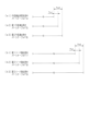
MPU52は遊技に際し各種カウンタ情報を用いて、大当たり発生抽選、特図表示部37aの表示の設定、図柄表示装置41の図柄表示の設定、普図表示部38aの表示の設定などを行うこととしており、具体的には、図6に示すように、大当たり発生抽選に使用する当たり乱数カウンタC1と、15R確変大当たり結果や通常大当たり結果等の大当たり種別を判定する際に使用する大当たり種別カウンタC2と、図柄表示装置41が外れ変動する際のリーチ発生抽選に使用するリーチ乱数カウンタC3と、当たり乱数カウンタC1の初期値設定に使用する乱数初期値カウンタCINIと、特図表示部37a及び図柄表示装置41における変動表示時間を決定する変動種別カウンタCSとを用いることとしている。さらに、第2作動口34の普電役物34aを電役開放状態とするか否かの抽選に使用する普電役物開放カウンタC4を用いることとしている。なお、これら各カウンタC1~C3,CINI,CS,C4は、抽選カウンタ用バッファ54aに設けられている。
During the game, the
各カウンタC1~C3,CINI,CS,C4は、その更新の都度前回値に1が加算され、最大値に達した後「0」に戻るループカウンタとなっている。当たり乱数カウンタC1、大当たり種別カウンタC2及びリーチ乱数カウンタC3に対応した情報は、第1作動口33又は第2作動口34への入賞が発生した場合に、取得情報記憶手段としての保留格納エリア54bに格納される。
Each of the counters C1 to C3, CINI, CS, and C4 is a loop counter in which 1 is added to the previous value each time it is updated, and returns to "0" after reaching the maximum value. Information corresponding to the hit random number counter C1, jackpot type counter C2, and reach random number counter C3 is stored in the
保留格納エリア54bは、保留用エリアREと、実行エリアAEとを備えている。保留用エリアREは、第1保留エリアRE1、第2保留エリアRE2、第3保留エリアRE3及び第4保留エリアRE4を備えており、第1作動口33又は第2作動口34への入賞履歴に合わせて、当たり乱数カウンタC1、大当たり種別カウンタC2及びリーチ乱数カウンタC3の各数値情報が保留情報として、いずれかの保留エリアRE1~RE4に格納される。
The
第1保留エリアRE1~第4保留エリアRE4には、第1作動口33又は第2作動口34への入賞が複数回連続して発生した場合に、第1保留エリアRE1→第2保留エリアRE2→第3保留エリアRE3→第4保留エリアRE4の順に各数値情報が時系列的に格納されていく。このように4つの保留エリアRE1~RE4が設けられていることにより、第1作動口33又は第2作動口34への遊技球の入賞履歴が最大4個まで保留記憶されるようになっている。なお、保留記憶可能な数は、4個に限定されることはなく任意であり、2個、3個又は5個以上といったように他の複数であってもよく、単数であってもよい。実行エリアAEは、特図表示部37aの変動表示を開始する際に、保留用エリアREの第1保留エリアRE1に格納された各値を移動させるためのエリアであり、1遊技回の開始に際しては実行エリアAEに記憶されている各種数値情報に基づいて、当否判定などが行われる。
In the first holding area RE1 to the fourth holding area RE4, if winnings to the
各カウンタについて詳しくは、当たり乱数カウンタC1は、例えば0~599の範囲内で順に「1」ずつ加算され、最大値に達した後「0」に戻る構成となっている。特に当たり乱数カウンタC1が1周した場合、その時点の乱数初期値カウンタCINIの値が当該当たり乱数カウンタC1の初期値として読み込まれる。なお、乱数初期値カウンタCINIは、当たり乱数カウンタC1と同様のループカウンタである(値=0~599)。当たり乱数カウンタC1は定期的に更新され、遊技球が第1作動口33又は第2作動口34に入賞したタイミングで保留格納エリア54bに格納される。
In detail about each counter, the winning random number counter C1 is configured such that, for example, the winning random number counter C1 is sequentially incremented by "1" within the range of 0 to 599, and returns to "0" after reaching the maximum value. In particular, when the winning random number counter C1 completes one round, the value of the random number initial value counter CINI at that time is read as the initial value of the winning random number counter C1. Note that the random number initial value counter CINI is a loop counter similar to the winning random number counter C1 (value=0 to 599). The winning random number counter C1 is updated regularly, and is stored in the holding
大当たり当選となる乱数の値は、ROM53に当否テーブルとして記憶されている。当否テーブルとしては、低確率モード用の当否テーブルと、高確率モード用の当否テーブルとが設定されている。つまり、本パチンコ機10は、大当たり発生抽選手段における抽選モードとして、低確率モードと高確率モードとが設定されている。
The random number value for winning the jackpot is stored in the
上記抽選に際して低確率モード用の当否テーブルが参照されることとなる遊技状態下では、大当たり当選となる乱数の数は2個である。一方、上記抽選に際して高確率モード用の当否テーブルが参照されることとなる遊技状態下では、大当たり当選となる乱数の数は20個である。なお、低確率モードよりも高確率モードの方の当選確率が高くなるのであれば、上記当選となる乱数の数は任意である。 Under the gaming state in which the low probability mode win/fail table is referred to during the above-mentioned lottery, the number of random numbers that result in a jackpot is two. On the other hand, under the gaming condition in which the high probability mode win/fail table is referred to during the above-mentioned lottery, the number of random numbers that result in a jackpot is 20. Note that the number of random numbers that result in a win is arbitrary, as long as the winning probability is higher in the high probability mode than in the low probability mode.
大当たり種別カウンタC2は、0~29の範囲内で順に「1」ずつ加算され、最大値に達した後「0」に戻る構成となっている。大当たり種別カウンタC2は定期的に更新され、遊技球が第1作動口33又は第2作動口34に入賞したタイミングで保留格納エリア54bに格納される。
The jackpot type counter C2 is configured to be incremented by "1" in order within the range of 0 to 29, and return to "0" after reaching the maximum value. The jackpot type counter C2 is updated regularly, and is stored in the holding
本パチンコ機10では、複数の大当たり結果が設定されている。これら複数の大当たり結果は、(1)開閉実行モードにおける特電入賞装置32の開閉制御の態様、(2)開閉実行モード終了後の大当たり発生抽選手段における抽選モード、(3)開閉実行モード終了後の第2作動口34の普電役物34aにおけるサポートモード、という3つの条件に差異を設けることにより、複数の大当たり結果が設定されている。
In this
開閉実行モードにおける特電入賞装置32の開閉制御の態様としては、開閉実行モードが開始されてから終了するまでの間における特電入賞装置32への入賞の発生頻度が相対的に高低となるように高頻度入賞モードと低頻度入賞モードとが設定されている。具体的には、高頻度入賞モードでは、開閉実行モードの開始から終了までに、大入賞口の開閉が15回行われるとともに、1回の開放は30secが経過するまで又は大入賞口への入賞個数が10個となるまで継続される。一方、低頻度入賞モードでは、開閉実行モードの開始から終了までに、大入賞口の開閉が2回行われるとともに、1回の開放は0.2secが経過するまで又は大入賞口への入賞個数が6個となるまで継続される。
The mode of opening/closing control of the special
本パチンコ機10では、発射操作装置28が遊技者により操作されている状況では、0.6secに1個の遊技球が遊技領域PAに向けて発射されるように遊技球発射機構58が駆動制御される。これに対して、低頻度入賞モードでは、上記のとおり1回の大入賞口の開放時間は0.2secとなっている。つまり、低頻度入賞モードでは、遊技球の発射周期よりも1回の大入賞口の開放時間が短くなっている。したがって、低頻度入賞モードの開閉実行モードでは実質的に遊技球の入賞が発生しない。
In this
なお、高頻度入賞モード及び低頻度入賞モードにおける大入賞口の開閉回数、1回の開放に対する開放制限時間及び1回の開放に対する開放制限個数は、高頻度入賞モードの方が低頻度入賞モードよりも、開閉実行モードが開始されてから終了するまでの間における特電入賞装置32への入賞の発生頻度が高くなるのであれば、上記の値に限定されることはなく任意である。具体的には、高頻度入賞モードの方が低頻度入賞モードよりも、開閉回数が多い、1回の開放に対する開放制限時間が長い又は1回の開放に対する開放制限個数が多く設定されていればよい。
In addition, in the high-frequency winning mode and the low-frequency winning mode, the number of openings and closings of the big winning opening, the opening time limit for one opening, and the opening limit number for one opening are higher in the high-frequency winning mode than in the low-frequency winning mode. However, the value is not limited to the above value and may be any value as long as the frequency of winnings in the special
但し、高頻度入賞モードと低頻度入賞モードとの間での特典の差異を明確にする上では、低頻度入賞モードの開閉実行モードでは、実質的に特電入賞装置32への入賞が発生しない構成とするとよい。例えば、高頻度入賞モードでは、1回の開放について、遊技球の発射周期と開放制限個数との積を、開放制限時間よりも短く設定する一方、低頻度入賞モードでは、1回の開放について、遊技球の発射周期と開放制限個数との積を、開放制限時間よりも長く設定する構成としてもよい。また、遊技球の発射間隔及び1回の大入賞口の開放時間が上記のものでなかったとしても、低頻度入賞モードでは、前者よりも後者の方が短くなるように設定することで、実質的に特電入賞装置32への入賞が発生しない構成を容易に実現することができる。
However, in order to clarify the difference in benefits between the high-frequency winning mode and the low-frequency winning mode, in the opening/closing execution mode of the low-frequency winning mode, there is a configuration in which winnings to the special
第2作動口34の普電役物34aにおけるサポートモードとしては、遊技領域PAに対して同様の態様で遊技球の発射が継続されている状況で比較した場合に、第2作動口34の普電役物34aが単位時間当たりに開放状態となる頻度が相対的に高低となるように、低頻度サポートモードと高頻度サポートモードとが設定されている。
As for the support mode of the general utility accessory 34a of the
具体的には、低頻度サポートモードと高頻度サポートモードとでは、普電役物開放カウンタC4を用いた電動役物開放抽選における電役開放状態当選となる確率は同一(例えば、共に4/5)となっているが、高頻度サポートモードでは低頻度サポートモードよりも、電役開放状態当選となった際に普電役物34aが開放状態となる回数が多く設定されており、さらに1回の開放時間が長く設定されている。この場合、高頻度サポートモードにおいて電役開放状態当選となり普電役物34aの開放状態が複数回発生する場合において、1回の開放状態が終了してから次の開放状態が開始されるまでの閉鎖時間は、1回の開放時間よりも短く設定されている。さらにまた、高頻度サポートモードでは低頻度サポートモードよりも、1回の電動役物開放抽選が行われてから次の電動役物開放抽選が行われる上で最低限確保される確保時間として短い時間が選択されるように設定されている。 Specifically, in the low-frequency support mode and the high-frequency support mode, the probability of winning the electric role opening state in the electric utility role opening lottery using the electric utility role opening counter C4 is the same (for example, both are 4/5 ), however, in the high-frequency support mode, the number of times that the general electric utility object 34a becomes open when the electric role open state is won is set to be greater than that in the low-frequency support mode, and one more time. The opening time is set to be long. In this case, in the high-frequency support mode, when the power utility open state is won and the power utility object 34a is opened multiple times, the period from the end of one open state to the start of the next open state is The closing time is set shorter than the one-time opening time. Furthermore, in the high-frequency support mode, the minimum secured time between one electric accessory opening lottery and the next electric accessory opening lottery is shorter than the low-frequency support mode. is set to be selected.
上記のように高頻度サポートモードでは、低頻度サポートモードよりも第2作動口34への入賞が発生する確率が高くなる。換言すれば、低頻度サポートモードでは、第2作動口34よりも第1作動口33への入賞が発生する確率が高くなるが、高頻度サポートモードでは、第1作動口33よりも第2作動口34への入賞が発生する確率が高くなる。そして、第2作動口34への入賞が発生した場合には、所定個数の遊技球の払出が実行されるため、高頻度サポートモードでは、遊技者は持ち球をあまり減らさないようにしながら遊技を行うことができる。
As described above, in the high-frequency support mode, the probability of winning the
なお、高頻度サポートモードを低頻度サポートモードよりも単位時間当たりに電役開放状態となる頻度を高くする上での構成は、上記のものに限定されることはなく、例えば電動役物開放抽選における電役開放状態当選となる確率を高くする構成としてもよい。また、1回の電動役物開放抽選が行われてから次の電動役物開放抽選が行われる上で確保される確保時間(例えば、スルーゲート35への入賞に基づき普図表示部38aにて実行される変動表示の時間)が複数種類用意されている構成においては、高頻度サポートモードでは低頻度サポートモードよりも、短い確保時間が選択され易い又は平均の確保時間が短くなるように設定されていてもよい。さらには、開放回数を多くする、開放時間を長くする、1回の電動役物開放抽選が行われてから次の電動役物開放抽選が行われる上で確保される確保時間を短くする(すなわち、普図表示部38aにおける1回の変動表示時間を短くする)、当該確保時間の平均時間を短くする及び当選確率を高くするのうち、いずれか1条件又は任意の組合せの条件を適用することで、低頻度サポートモードに対する高頻度サポートモードの有利性を高めてもよい。 Note that the configuration for making the high-frequency support mode more frequently open to the electric utility role per unit time than the low-frequency support mode is not limited to the above, and may include, for example, a lottery for opening electric utility objects. It may be configured to increase the probability of winning the electric combination open state in . In addition, the secured time that is secured after one electric accessory opening lottery is held and the next electric accessory opening lottery is held (for example, in the general map display section 38a based on winnings in the through gate 35). In a configuration in which multiple types of variable display times are prepared, it is easier to select a shorter securing time in the high-frequency support mode than in the low-frequency support mode, or the average securing time is set to be shorter. You can leave it there. Furthermore, increasing the number of openings, lengthening the opening time, and shortening the time secured between one electric accessory opening lottery and the next electric accessory opening lottery (i.e. , shortening the one-time variable display time on the common map display section 38a), shortening the average time of the secured time, and increasing the winning probability, any one condition or any combination of conditions may be applied. This may increase the advantage of the high-frequency support mode over the low-frequency support mode.
大当たり種別カウンタC2に対する遊技結果の振分先は、ROM53に振分テーブルとして記憶されている。そして、かかる振分先として、通常大当たり結果と、明示2R確変大当たり結果と、15R確変大当たり結果とが設定されている。
The destinations to which game results are distributed to the jackpot type counter C2 are stored in the
通常大当たり結果は、開閉実行モードが高頻度入賞モードとなり、さらに開閉実行モードの終了後には、大当たり発生抽選モードが低確率モードとなるとともに、サポートモードが高頻度サポートモードとなる大当たり結果である。但し、この高頻度サポートモードは、移行後において遊技回数が終了基準回数(具体的には、100回)に達した場合に低頻度サポートモードに移行する。換言すれば、通常大当たり結果は、通常大当たり状態へ遊技状態を移行させる大当たり結果である。 The normal jackpot result is a jackpot result in which the opening/closing execution mode becomes a high-frequency winning mode, and furthermore, after the opening/closing execution mode ends, the jackpot occurrence lottery mode becomes a low probability mode and the support mode becomes a high-frequency support mode. However, this high-frequency support mode shifts to the low-frequency support mode when the number of games has reached the end standard number of times (specifically, 100 times) after the shift. In other words, the normal jackpot result is a jackpot result that causes the gaming state to shift to the normal jackpot state.
明示2R確変大当たり結果は、開閉実行モードが低頻度入賞モードとなり、さらに開閉実行モードの終了後には、大当たり発生抽選モードが高確率モードとなるとともに、サポートモードが高頻度サポートモードとなる大当たり結果である。これら高確率モード及び高頻度サポートモードは、大当たり発生抽選における抽選結果が大当たり状態当選となり、それによる大当たり状態に移行するまで継続する。換言すれば、明示2R確変大当たり結果は、明示2R確変大当たり状態へ遊技状態を移行させる大当たり結果である。 The explicit 2R definite variable jackpot result is a jackpot result in which the opening/closing execution mode becomes the low-frequency winning mode, and after the opening/closing execution mode ends, the jackpot occurrence lottery mode becomes the high probability mode and the support mode becomes the high-frequency support mode. be. These high-probability mode and high-frequency support mode continue until the lottery result in the jackpot occurrence lottery becomes a jackpot state win and the state shifts to the jackpot state accordingly. In other words, the explicit 2R definite variable jackpot result is a jackpot result that causes the gaming state to shift to the explicit 2R definite variable jackpot state.
15R確変大当たり結果は、開閉実行モードが高頻度入賞モードとなり、さらに開閉実行モードの終了後には、大当たり発生抽選モードが高確率モードとなるとともに、サポートモードが高頻度サポートモードとなる大当たり結果である。これら高確率モード及び高頻度サポートモードは、大当たり発生抽選における抽選結果が大当たり状態当選となり、それによる大当たり状態に移行するまで継続する。換言すれば、15R確変大当たり結果は、15R確変大当たり状態へ遊技状態を移行させる大当たり結果である。 The 15R probability variable jackpot result is a jackpot result in which the opening/closing execution mode becomes the high-frequency winning mode, and furthermore, after the opening/closing execution mode ends, the jackpot occurrence lottery mode becomes the high-probability mode and the support mode becomes the high-frequency support mode. . These high-probability mode and high-frequency support mode continue until the lottery result in the jackpot occurrence lottery becomes a jackpot state win and the state shifts to the jackpot state accordingly. In other words, the 15R probability variable jackpot result is a jackpot result that causes the gaming state to shift to the 15R probability variable jackpot state.
なお、上記各遊技状態との関係で通常遊技状態とは、大当たり発生抽選モードが低確率モードであり、サポートモードが低頻度サポートモードである状態をいう。 In relation to the above gaming states, the normal gaming state refers to a state where the jackpot occurrence lottery mode is a low probability mode and the support mode is a low frequency support mode.
振分テーブルでは、「0~29」の大当たり種別カウンタC2の値のうち、「0~9」が通常大当たり結果に対応しており、「10~14」が明示2R確変大当たり結果に対応しており、「15~29」が15R確変大当たり結果に対応している。 In the distribution table, among the values of jackpot type counter C2 of "0 to 29", "0 to 9" correspond to normal jackpot results, and "10 to 14" correspond to explicit 2R definite variable jackpot results. ``15-29'' corresponds to the 15R probability-variable jackpot result.
上記のように、確変大当たり結果として、明示2R確変大当たり結果が設定されていることにより、確変大当たり結果の態様が多様化する。すなわち、2種類の確変大当たり結果を比較した場合、遊技者にとっての有利度合いは、開閉実行モードにおいて高頻度入賞モードとなり且つサポートモードでは高頻度サポートモードとなる15R確変大当たり結果が最も高く、開閉実行モードにおいて低頻度入賞モードとなるもののサポートモードでは高頻度サポートモードとなる明示2R確変大当たり結果が最も低くなる。これにより、遊技の単調化が抑えられ、遊技への注目度を高めることが可能となる。 As mentioned above, since the explicit 2R definite variable jackpot result is set as the definite variable jackpot result, the form of the definite variable jackpot result is diversified. That is, when comparing the two types of variable probability jackpot results, the degree of advantage for the player is the highest for the 15R probability variable jackpot result, which is a high-frequency winning mode in the opening/closing execution mode and a high-frequency support mode in the support mode. In the mode, it becomes a low-frequency winning mode, but in the support mode, the explicit 2R probability variable jackpot result, which becomes a high-frequency support mode, is the lowest. This prevents the game from becoming monotonous and increases the level of attention to the game.
なお、確変大当たり結果の一種として、開閉実行モードが低頻度入賞モードとなり、さらに開閉実行モードの終了後には、大当たり発生抽選モードが高確率モードとなるとともに、サポートモードがそれまでのモードに維持されることとなる非明示2R確変大当たり結果が含まれていてもよい。この場合、確変大当たり結果のさらなる多様化が図られる。 In addition, as a type of probability variable jackpot result, the opening/closing execution mode becomes the low-frequency winning mode, and after the opening/closing execution mode ends, the jackpot occurrence lottery mode becomes the high probability mode, and the support mode remains the previous mode. It may also include an unspecified 2R probability variable jackpot result. In this case, the probability-variable jackpot results are further diversified.
さらにまた、大当たり発生抽選における外れ結果の一種として、低頻度入賞モードの開閉実行モードに移行するとともに、その終了後において大当たり発生抽選モード及びサポートモードの移行が発生しない特別外れ結果が含まれていてもよい。上記のような非明示2R確変大当たり結果と当該特別外れ結果との両方が設定されている構成においては、開閉実行モードが低頻度入賞モードに移行すること、及びサポートモードがそれまでのモードに維持されることで共通しているのに対して、大当たり発生抽選モードの移行態様が異なっていることにより、例えば通常遊技状態において非明示2R確変大当たり結果又は特別外れ結果の一方が発生した場合に、それが実際にいずれの結果に対応しているのかを遊技者に予測させることが可能となる。 Furthermore, as a type of losing result in the jackpot lottery, there is a special losing result that shifts to the opening/closing execution mode of the low-frequency winning mode and does not switch to the jackpot lottery mode and support mode after the end of that mode. Good too. In a configuration where both the unspecified 2R definite variable jackpot result and the special winning result are set as described above, the opening/closing execution mode will shift to the low-frequency winning mode, and the support mode will remain the previous mode. However, due to the difference in the transition mode of the jackpot occurrence lottery mode, for example, if either the undisclosed 2R probability variable jackpot result or the special winning result occurs in the normal gaming state, It becomes possible for the player to predict which result this actually corresponds to.
リーチ乱数カウンタC3は、例えば0~238の範囲内で順に「1」ずつ加算され、最大値に達した後「0」に戻る構成となっている。リーチ乱数カウンタC3は定期的に更新され、遊技球が第1作動口33又は第2作動口34に入賞したタイミングで保留格納エリア54bに格納される。
The reach random number counter C3 is configured to increment sequentially by 1 within the range of 0 to 238, for example, and return to 0 after reaching the maximum value. The reach random number counter C3 is updated regularly, and is stored in the holding
ここで、本パチンコ機10には、図柄表示装置41における表示演出の一種として期待演出が設定されている。期待演出とは、図柄の変動表示を行うことが可能な図柄表示装置41を備え、特電入賞装置32の開閉実行モードが高頻度入賞モードとなる遊技回では変動表示後の停止表示結果が特別表示結果となる遊技機において、図柄表示装置41における図柄の変動表示が開始されてから停止表示結果が導出表示される前段階で、前記特別表示結果となり易い変動表示状態であると遊技者に思わせるための表示状態をいう。
Here, in this
期待演出には、上記リーチ演出と、当該リーチ演出が発生する前段階などにおいてリーチ演出の発生や特別表示結果の発生を期待させるための予告演出との2種類が設定されている。 Two types of expected performance are set: the above-mentioned ready-to-reach performance and a preview performance for making the user expect the occurrence of a ready-to-reach performance or a special display result at a stage before the relevant ready-to-reach performance occurs.
リーチ演出には、図柄表示装置41の表示面Pに表示される複数の図柄列のうち一部の図柄列について図柄を停止表示させることで、高頻度入賞モードの発生に対応した大当たり図柄の組合せが成立する可能性があるリーチ図柄の組合せを表示し、その状態で残りの図柄列において図柄の変動表示を行う表示状態が含まれる。また、上記のようにリーチ図柄の組合せを表示した状態で、残りの図柄列において図柄の変動表示を行うとともに、その背景画像において所定のキャラクタなどを動画として表示することによりリーチ演出を行うものや、リーチ図柄の組合せを縮小表示させる又は非表示とした上で、表示面Pの略全体において所定のキャラクタなどを動画として表示することによりリーチ演出を行うものが含まれる。
For the reach effect, by stopping and displaying the symbols for some of the plurality of symbol rows displayed on the display surface P of the
リーチ演出について具体的には、図柄の変動表示を終了させる前段階として、図柄表示装置41の表示面P内の予め設定された有効ライン上に、高頻度入賞モードの発生に対応した大当たり図柄の組合せが成立する可能性のあるリーチ図柄の組合せを停止表示させることによりリーチラインを形成させ、当該リーチラインが形成されている状況下において最終停止図柄列により図柄の変動表示を行うことである。
Specifically, regarding the reach effect, as a step before ending the fluctuating display of symbols, a jackpot symbol corresponding to the occurrence of the high-frequency winning mode is displayed on a preset active line on the display surface P of the
図4の表示内容について具体的に説明すると、最初に上段の図柄列Z1において図柄の変動表示が終了され、さらに下段の図柄列Z3において図柄の変動表示が終了された状態において、いずれかの有効ラインL1~L5に同一の数字が付された主図柄が停止表示されることでリーチラインが形成され、当該リーチラインが形成されている状況化において中段の図柄列Z2において図柄の変動表示が行われることでリーチ演出となる。そして、高頻度入賞モードが発生する場合には、リーチラインを形成している主図柄と同一の数字が付された主図柄がリーチライン上に停止表示されるようにして中段の図柄列Z2における図柄の変動表示が終了される。 To specifically explain the display contents in FIG. 4, first, the fluctuating display of symbols is finished in the upper symbol row Z1, and then the fluctuating display of symbols is finished in the lower symbol row Z3. A reach line is formed by stopping and displaying the main symbols with the same number on lines L1 to L5, and in a situation where the reach line is formed, a fluctuating display of symbols is performed in the middle symbol row Z2. By being caught, it becomes a reach performance. When the high-frequency winning mode occurs, the main symbols with the same numbers as the main symbols forming the reach line are stopped and displayed on the reach line, so that the main symbols in the middle symbol row Z2 The fluctuating display of symbols is ended.
予告演出には、図柄表示装置41の表示面Pにおいて図柄の変動表示が開始されてから、全ての図柄列Z1~Z3にて図柄が変動表示されている状況において、又は一部の図柄列であって複数の図柄列にて図柄が変動表示されている状況において、図柄列Z1~Z3上の図柄とは別にキャラクタを表示させる態様が含まれる。また、背景画像をそれまでの態様とは異なる所定の態様とするものや、図柄列Z1~Z3上の図柄をそれまでの態様とは異なる所定の態様とするものも含まれる。かかる予告演出は、リーチ演出が行われる場合及びリーチ演出が行われない場合のいずれの遊技回においても発生し得るが、リーチ演出の行われる場合の方がリーチ演出の行われない場合よりも高確率で発生するように設定されている。
The preview performance is performed in a situation where the symbols are being displayed in a variable manner in all the symbol rows Z1 to Z3 after the start of the fluctuating display of the symbols on the display surface P of the
リーチ演出は、開閉実行モードに移行する遊技回では、リーチ乱数カウンタC3の値に関係なく実行される。また、開閉実行モードに移行しない遊技回では、ROM53のリーチ用テーブル記憶エリアに記憶されたリーチ用テーブルを参照して、所定のタイミングで取得したリーチ乱数カウンタC3がリーチ演出の発生に対応している場合に実行される。一方、予告演出を行うか否かの決定は、主制御装置50において行うのではなく、音声発光制御装置60において行われる。
The ready-to-win effect is executed regardless of the value of the ready-to-reach random number counter C3 in the game round that shifts to the opening/closing execution mode. In addition, in game rounds that do not shift to the opening/closing execution mode, the reach random number counter C3 acquired at a predetermined timing refers to the reach table stored in the reach table storage area of the
変動種別カウンタCSは、例えば0~198の範囲内で順に「1」ずつ加算され、最大値に達した後「0」に戻る構成となっている。変動種別カウンタCSは、特図表示部37aにおける変動表示時間と、図柄表示装置41における図柄の変動表示時間とをMPU52において決定する上で用いられる。変動種別カウンタCSは、後述するタイマ割込み処理が1回実行される毎に1回更新され、後述するメイン処理の残余時間内でも繰り返し更新される。そして、特図表示部37aにおける変動表示の開始時及び図柄表示装置41による図柄の変動開始時における変動パターン決定に際して変動種別カウンタCSのバッファ値が取得される。なお、変動表示時間の決定に際しては、ROM53の変動表示時間テーブル記憶エリアに予め記憶されている変動表示時間テーブルが参照される。
The variation type counter CS is configured such that it is incremented by "1" sequentially within the range of 0 to 198, for example, and returns to "0" after reaching the maximum value. The variation type counter CS is used by the
普電役物開放カウンタC4は、例えば、0~250の範囲内で順に「1」ずつ加算され、最大値に達した後「0」に戻る構成となっている。普電役物開放カウンタC4は定期的に更新され、スルーゲート35に遊技球が入賞したタイミングで電役保留エリア54cに格納される。そして、所定のタイミングにおいて、その格納された普電役物開放カウンタC4の値によって普電役物34aを開放状態に制御するか否かの抽選が行われる。
For example, the general utility goods release counter C4 is configured to increment sequentially by "1" within the range of 0 to 250, and return to "0" after reaching the maximum value. The common electric utility object opening counter C4 is updated regularly, and is stored in the electric
MPU52の出力側には、払出制御装置55が接続されているとともに、電源・発射制御装置57が接続されている。払出制御装置55には、例えば、上記入賞対応入球部への入賞判定結果に基づいて賞球コマンドが送信される。払出制御装置55は、主制御装置50から受信した賞球コマンドに基づいて、払出装置56により賞球や貸し球の払出制御を行う。電源・発射制御装置57には、発射操作装置28が操作されていることに基づいて発射許可コマンドが送信される。電源・発射制御装置57は、主制御装置50から受信した発射許可コマンドに基づいて、遊技球発射機構58を駆動させ遊技球を遊技領域PAに向けて発射させる。
A dispensing
また、MPU52の出力側には、特図表示部37a及び普図表示部38aが接続されており、これら特図表示部37a及び普図表示部38aの表示制御がMPU52により直接行われる。つまり、各遊技回に際しては、MPU52において特図表示部37aの表示制御が実行される。また、普電役物34aを開放状態とするか否かの抽選結果を明示する場合に、MPU52において普図表示部38aの表示制御が実行される。
Moreover, the special
MPU52の出力側には、特電入賞装置32の開閉扉を開閉動作させる特電入賞駆動部、及び第2作動口34の普電役物34aを開閉動作させる普電役物駆動部が接続されている。つまり、開閉実行モードにおいては大入賞口が開閉されるように、MPU52において特電入賞駆動部の駆動制御が実行される。また、普電役物34aの開放状態当選となった場合には、普電役物34aが開閉されるように、MPU52において普電役物駆動部の駆動制御が実行される。また、MPU52の出力側には、音声発光制御装置60が接続されており、当該音声発光制御装置60に対して演出用の各種コマンドを送信する。
Connected to the output side of the
ここで、MPU52にて実行される処理について説明する。かかるMPU52の処理としては大別して、電源投入に伴い起動されるメイン処理と、定期的に(本実施の形態では4msec周期で)起動されるタイマ割込み処理とがある。
Here, the processing executed by the
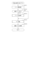
図7はメイン処理を示すフローチャートである。ステップS101では、電源投入ウェイト処理を実行する。当該電源投入ウェイト処理では、例えばメイン処理が起動されてからウェイト用の所定時間(具体的には1sec)が経過するまで次の処理に進行することなく待機する。かかる電源投入ウェイト処理の実行期間において図柄表示装置41の動作開始及び初期設定が完了することとなる。続くステップS102ではRAM54のアクセスを許可するとともに、ステップS103にてMPU52の内部機能レジスタの設定を行う。
FIG. 7 is a flowchart showing the main processing. In step S101, a power-on wait process is executed. In the power-on wait process, for example, the main process waits without proceeding to the next process until a predetermined wait time (specifically, 1 sec) has elapsed after the main process is started. The operation start and initial setting of the
その後、ステップS104では、電源・発射制御装置57に設けられたRAM消去スイッチが手動操作されているか否かを判定し、続くステップS105では、RAM54の停電フラグに「1」がセットされているか否かを判定する。また、ステップS106ではチェックサムを算出するチェックサム算出処理を実行し、続くステップS107ではそのチェックサムが電源遮断時に保存したチェックサムと一致するか否か、すなわち記憶保持されたデータの有効性を判定する。
Thereafter, in step S104, it is determined whether the RAM erase switch provided in the power supply/
本パチンコ機10では、例えば遊技ホールの営業開始時など、電源投入時にRAMデータを初期化する場合にはRAM消去スイッチを押しながら電源が投入される。したがって、RAM消去スイッチが押されていれば、ステップS108の処理に移行する。また、電源遮断の発生情報が設定されていない場合や、チェックサムにより記憶保持されたデータの異常が確認された場合も同様にステップS108の処理に移行する。ステップS108では、RAM54をクリアする。その後、ステップS109に進む。
In this
一方、RAM消去スイッチが押されていない場合には、停電フラグに「1」がセットされていること、及びチェックサムが正常であることを条件に、ステップS108の処理を実行することなくステップS109に進む。ステップS109では、電源投入設定処理を実行する。電源投入設定処理では、停電フラグの初期化といったRAM54の所定のエリアを初期値に設定するとともに、現状の遊技状態を認識させるために現状の遊技状態に対応したコマンドを音声発光制御装置60に送信する。
On the other hand, if the RAM erase switch is not pressed, on condition that the power outage flag is set to "1" and the checksum is normal, step S109 is performed without executing the process of step S108. Proceed to. In step S109, a power-on setting process is executed. In the power-on setting process, a predetermined area of the
その後、ステップS110~ステップS113の残余処理に進む。つまり、MPU52はタイマ割込み処理を定期的に実行する構成であるが、1のタイマ割込み処理と次のタイマ割込み処理との間に残余時間が生じることとなる。この残余時間は各タイマ割込み処理の処理完了時間に応じて変動することとなるが、かかる不規則な時間を利用してステップS110~ステップS113の残余処理を繰り返し実行する。この点、当該ステップS110~ステップS113の残余処理は非定期的に実行される非定期処理であると言える。
Thereafter, the process proceeds to the remaining processing of steps S110 to S113. That is, although the
残余処理では、まずステップS110にて、タイマ割込み処理の発生を禁止するために割込み禁止の設定を行う。続くステップS111では、乱数初期値カウンタCINIの更新を行う乱数初期値更新処理を実行するとともに、ステップS112にて変動種別カウンタCSの更新を行う変動用カウンタ更新処理を実行する。これらの更新処理では、RAM54の対応するカウンタから現状の数値情報を読み出し、その読み出した数値情報を1加算する処理を実行した後に、読み出し元のカウンタに上書きする処理を実行する。この場合、カウンタ値が最大値に達した際それぞれ「0」にクリアする。その後、ステップS113にて、タイマ割込み処理の発生を禁止している状態から許可する状態へ切り換える割込み許可の設定を行う。ステップS113の処理を実行したら、ステップS110に戻り、ステップS110~ステップS113の処理を繰り返す。
In the remaining processing, first, in step S110, interrupt prohibition is set to prohibit generation of timer interrupt processing. In the subsequent step S111, a random number initial value update process is executed to update the random number initial value counter CINI, and in step S112, a variation counter update process is executed to update the variation type counter CS. In these update processes, the current numerical information is read from the corresponding counter in the
次に、図8のフローチャートを参照しながらタイマ割込み処理を説明する。タイマ割込み処理は定期的(例えば4msec周期)に実行される。まずステップS201にて停電情報記憶処理を実行する。停電情報記憶処理では、停電監視基板から電源遮断の発生に対応した停電信号を受信しているか否かを監視し、停電の発生を特定した場合には停電時処理を実行する。 Next, timer interrupt processing will be explained with reference to the flowchart in FIG. The timer interrupt process is executed periodically (for example, every 4 msec). First, in step S201, a power outage information storage process is executed. In the power outage information storage process, it is monitored whether or not a power outage signal corresponding to the occurrence of a power cutoff is received from the power outage monitoring board, and if the occurrence of a power outage is identified, a power outage process is executed.
続くステップS202では抽選用乱数更新処理を実行する。抽選用乱数更新処理では、当たり乱数カウンタC1、大当たり種別カウンタC2、リーチ乱数カウンタC3及び普電役物開放カウンタC4の更新を実行する。具体的には、当たり乱数カウンタC1、大当たり種別カウンタC2、リーチ乱数カウンタC3及び普電役物開放カウンタC4から現状の数値情報を順次読み出し、それら読み出した数値情報をそれぞれ1加算する処理を実行した後に、読み出し元のカウンタに上書きする処理を実行する。この場合、カウンタ値が最大値に達した際それぞれ「0」にクリアする。その後、ステップS203ではステップS111と同様に乱数初期値更新処理を実行するとともに、ステップS204にてステップS112と同様に変動用カウンタ更新処理を実行する。 In the following step S202, random number update processing for lottery is executed. In the random number update process for lottery, the winning random number counter C1, the jackpot type counter C2, the reach random number counter C3, and the general utility object opening counter C4 are updated. Specifically, the current numerical information was sequentially read from the hit random number counter C1, the jackpot type counter C2, the reach random number counter C3, and the general utility goods release counter C4, and a process was performed in which each of the read numerical information was incremented by 1. Afterwards, a process is executed to overwrite the reading source counter. In this case, each counter value is cleared to "0" when it reaches the maximum value. Thereafter, in step S203, a random number initial value update process is executed as in step S111, and in step S204, a variation counter update process is executed as in step S112.
続くステップS205では、不正用の監視対象として設定されている所定の事象が発生しているか否かを監視する不正検知処理を実行する。当該不正検知処理では、複数種類の事象の発生を監視し、所定の事象が発生していることを確認することで、RAM54に設けられた遊技停止用フラグに「1」をセットする。
In the subsequent step S205, fraud detection processing is executed to monitor whether or not a predetermined event set as a monitoring target for fraud has occurred. In the fraud detection process, the occurrence of a plurality of types of events is monitored, and by confirming that a predetermined event has occurred, a game stop flag provided in the
続くステップS206では、上記遊技停止用フラグに「1」がセットされているか否かを判定することで、遊技の進行を停止している状態であるか否かを判定する。ステップS206にて否定判定をした場合に、ステップS207以降の処理を実行する。 In the following step S206, it is determined whether or not the progress of the game is stopped by determining whether or not the game stop flag is set to "1". If a negative determination is made in step S206, the processes from step S207 onwards are executed.
ステップS207では、ポート出力処理を実行する。ポート出力処理では、前回のタイマ割込み処理において出力情報の設定が行われている場合に、その出力情報に対応した出力を各種駆動部に行うための処理を実行する。例えば、特電入賞装置32を開放状態に切り換えるべき情報が設定されている場合には特電入賞駆動部への駆動信号の出力を開始させ、閉鎖状態に切り換えるべき情報が設定されている場合には当該駆動信号の出力を停止させる。また、第2作動口34の普電役物34aを開放状態に切り換えるべき情報が設定されている場合には普電役物駆動部への駆動信号の出力を開始させ、閉鎖状態に切り換えるべき情報が設定されている場合には当該駆動信号の出力を停止させる。
In step S207, port output processing is executed. In the port output processing, when output information has been set in the previous timer interrupt processing, processing is executed to output to various drive units in accordance with the output information. For example, if information to switch the special electric
続くステップS208では、読み込み処理を実行する。読み込み処理では、停電信号及び入賞信号以外の信号の読み込みを実行し、その読み込んだ情報を今後の処理にて利用するために記憶する。 In the following step S208, reading processing is executed. In the reading process, signals other than the power outage signal and winning signal are read, and the read information is stored for use in future processing.
続くステップS209では入賞検知処理を実行する。当該入賞検知処理では、各入賞検知センサから受信している信号を読み込むとともに、一般入賞口31、特電入賞装置32、第1作動口33、第2作動口34及びスルーゲート35への入賞の有無を特定する処理を実行する。
In the following step S209, winning detection processing is executed. In the winning detection process, the signals received from each winning detection sensor are read, and the presence or absence of a winning in the general winning
続くステップS210では、RAM54に設けられている複数種類のタイマカウンタの数値情報をまとめて更新するためのタイマ更新処理を実行する。この場合、記憶されている数値情報が減算されて更新されるタイマカウンタを集約して扱う構成であるが、減算式のタイマカウンタの更新及び加算式のタイマカウンタの更新の両方を集約して行う構成としてもよい。
In the subsequent step S210, a timer update process is executed to collectively update numerical information of a plurality of types of timer counters provided in the
続くステップS211では、遊技球の発射制御を行うための発射制御処理を実行する。発射操作装置28への発射操作が継続されている状況では、既に説明したとおり、所定の発射周期である0.6secに1個の遊技球が発射される。
In the following step S211, a firing control process for controlling the firing of game balls is executed. In a situation where the firing operation to the
続くステップS212では、入力状態監視処理として、ステップS208の読み込み処理にて読み込んだ情報に基づいて、各入賞検知センサの断線確認や、遊技機本体12や前扉枠14の開放確認を行う。
In the following step S212, as an input state monitoring process, the disconnection of each winning detection sensor and the opening of the gaming machine
続くステップS213では、遊技回の実行制御及び開閉実行モードの実行制御を行うための特図特電制御処理を実行する。当該特図特電制御処理では、保留格納エリア54bに記憶されている保留情報の数が上限数未満である状況で第1作動口33又は第2作動口34への入賞が発生した場合に、その時点における当たり乱数カウンタC1、大当たり種別カウンタC2及びリーチ乱数カウンタC3の各数値情報を保留情報として、保留格納エリア54bに時系列的に格納していく処理を実行する。また、特図特電制御処理では、遊技回中及び開閉実行モード中ではなく且つ保留情報が記憶されていることを条件に、その保留情報が大当たり当選に対応しているか否かを判定する大当たり発生抽選処理、及び大当たり当選に対応している場合にはその保留情報がいずれの大当たり結果に対応しているのかを判定する振分判定処理を実行する。また、特図特電制御処理では、大当たり発生抽選処理及び振分判定処理だけでなく、その保留情報が大当たり当選に対応していない場合には、その保留情報がリーチ発生に対応しているか否かを判定するリーチ判定処理を実行するとともに、その時点における変動種別カウンタCSの数値情報を利用して遊技回の変動表示時間を選択する処理を実行する。この場合、大当たり当選の有無、大当たり種別及びリーチ発生の有無に対応した変動表示時間テーブルをROM53から読み出し、その読み出した変動表示時間テーブルと、そのタイミングにおける変動種別カウンタCSの数値情報とから今回の遊技回の変動表示時間を決定する。そして、その決定した遊技回の変動表示時間の情報を含む変動用コマンドと、遊技結果の情報を含む種別コマンドとを、音声発光制御装置60に送信するとともに、特図表示部37aにおける絵柄の変動表示を開始させる。これにより、1遊技回が開始された状態となり、特図表示部37a及び図柄表示装置41にて遊技回用の演出が開始される。また、MPU52は変動用コマンド及び種別コマンドを送信した場合に変動表示時間の計測を開始する。
In the subsequent step S213, a special figure special electric control process is executed to control the execution of the game round and the opening/closing execution mode. In the special figure special electric control process, when a prize is won to the
また、特図特電制御処理では、1遊技回の実行中においては当該遊技回に対応する変動表示時間が経過した場合に、特図表示部37aにおいて今回の遊技回の大当たり発生抽選処理及び振分判定処理の結果に対応する停止結果を表示させ、さらに確定表示時間(具体的には0.5sec)の計測を開始する。そして、特図表示部37aに停止結果が表示された状態を確定表示時間に亘って維持させる。確定表示時間が経過した場合、今回の遊技回が外れ結果に対応しているのであれば、保留格納エリア54bに保留情報が記憶されていることを条件として、新たな遊技回を開始させるための処理を実行する。保留情報が記憶されていないのであれば、保留情報が新たに取得されるまで待機する。
In addition, in the special figure special electric control process, during the execution of one game round, when the variable display time corresponding to the game round has elapsed, the special
一方、今回の遊技回が大当たり結果に対応しているのであれば、開閉実行モードを開始させるための処理を実行する。この開始に際しては、開閉実行モードが開始されることを示すオープニングコマンドを音声発光制御装置60に送信する。また、特図特電制御処理では、各ラウンド遊技を開始させるための処理及び各ラウンド遊技を終了させるための処理を実行する。これら各処理に際して、ラウンド遊技が開始されることを示す開放コマンドを音声発光制御装置60に送信するとともに、ラウンド遊技が終了されることを示す閉鎖コマンドを音声発光制御装置60に送信する。また、特図特電制御処理では、開閉実行モードを終了させる場合にそのことを示すエンディングコマンドを音声発光制御装置60に送信するとともに、開閉実行モード後の大当たり発生抽選モードやサポートモードを設定するための処理を実行する。なお、開閉実行モードは、例えば3secといった期間に亘ってオープニング期間が発生し、このオープニング期間において開閉実行モードが発生したことを遊技者に認識可能とさせる演出が実行される。その後に、特電入賞装置32の開閉が実行されるラウンド遊技が所定回数実行される。そして、所定回数のラウンド遊技が実行された後に、例えば5secといった期間に亘ってエンディング期間が発生し、このエンディング期間において開閉実行モードが終了することを遊技者に認識可能とさせる演出が実行される。
On the other hand, if the current game round corresponds to the jackpot result, processing for starting the opening/closing execution mode is executed. At this start, an opening command indicating that the opening/closing execution mode is started is transmitted to the audio light
タイマ割込み処理においてステップS213の特図特電制御処理を実行した後は、ステップS214にて普図普電制御処理を実行する。普図普電制御処理では、スルーゲート35への入賞が発生している場合に普図側の保留情報を取得するための処理を実行するとともに、普図側の保留情報が記憶されている場合にその保留情報について開放判定を行い、さらにその開放判定を契機として普図用の演出を行うための処理を実行する。また、開放判定の結果に基づいて、第2作動口34の普電役物34aを開閉させる処理を実行する。
After executing the special figure special electric line control process in step S213 in the timer interrupt process, the general figure general electric line control process is executed in step S214. In the general map and general electric power control process, when a prize is won in the through
続くステップS215では、直前のステップS213及びステップS214の処理結果に基づいて、特図表示部37aに対応する保留情報の増減個数を特図保留表示部37bに反映させるための出力情報の設定を行うとともに、普図表示部38aに対応する保留情報の増減個数を普図保留表示部38bに反映させるための出力情報の設定を行う。また、ステップS215では、直前のステップS213及びステップS214の処理結果に基づいて、特図表示部37aの表示内容を更新させるための出力情報の設定を行うとともに、普図表示部38aの表示内容を更新させるための出力情報の設定を行う。
In the following step S215, based on the processing results of the immediately preceding step S213 and step S214, output information is set to reflect the increase or decrease in the number of pending information corresponding to the special
続くステップS216では、払出制御装置55から受信したコマンド及び信号の内容を確認し、その確認結果に対応した処理を行うための払出状態受信処理を実行する。また、ステップS217では、賞球コマンドを出力対象として設定するための払出出力処理を実行する。続くステップS218では、今回のタイマ割込み処理にて実行された各種処理の処理結果に応じた外部信号の出力の開始及び終了を制御するための外部情報設定処理を実行する。その後、本タイマ割込み処理を終了する。
In the subsequent step S216, the content of the command and signal received from the
<音声発光制御装置60>
次に、音声発光制御装置60について説明する。
<Audio light
Next, the audio
音声発光制御装置60は、図5に示すように、MPU62が搭載された音声発光制御基板61を具備している。MPU62には、当該MPU62により実行される各種の制御プログラムや固定値データを記憶したROM63と、そのROM63内に記憶される制御プログラムの実行に際して各種のデータ等を一時的に記憶するためのメモリであるRAM64と、割込回路、タイマ回路、データ入出力回路、乱数発生器としての各種カウンタ回路などが内蔵されている。
As shown in FIG. 5, the audio
なお、ROM63として、制御プログラムや固定値データの読み出しに際してランダムアクセスが可能であって、記憶保持に外部からの電力供給が不要な記憶手段(すなわち、不揮発性記憶手段)が用いられている。具体的には、NOR型キャッシュメモリが用いられている。但し、これに限定されることはなく、ランダムアクセスが可能であれば、ROM63として用いるメモリの種類は任意である。また、制御及び演算部分と、ROM63と、RAM64とが1チップ化されている構成は必須ではなく、各機能がそれぞれ別チップとして搭載されている構成としてもよく、一部の機能が別チップとして搭載されている構成としてもよい。
Note that as the
MPU62には、入力ポート及び出力ポートがそれぞれ設けられている。MPU62の入力側には主制御装置50及び演出用操作装置48が接続されている。MPU62の出力側には表示発光部44及びスピーカ部45が接続されているとともに、表示制御装置70の後述する表示CPU72が接続されている。
The
<表示制御装置70>
次に、表示制御装置70について説明する。
<
Next, the
表示制御装置70は、図5に示すように、表示CPU72と、ワークRAM73と、メモリモジュール74と、VRAM75と、ビデオディスプレイプロセッサ(VDP)76と、が搭載された表示制御基板71を備えている。
As shown in FIG. 5, the
表示CPU72は、表示制御装置70においてメイン制御部としての機能を有しており、制御プログラム等の読み出し、解釈及び実行を行う。詳細には、表示CPU72は表示制御基板71に搭載された入力ポート77に対してバスを介して接続されており、音声発光制御装置60から送信された各種コマンドは入力ポート77を通じて表示CPU72に入力される。なお、表示CPU72において音声発光制御装置60からコマンドを受信するとは、音声発光制御装置60からコマンドを直接受信する構成に限定されることはなく、中継基板に中継されたコマンドを受信する構成も含まれる。
The
表示CPU72は、バスを介してワークRAM73、メモリモジュール74及びVRAM75と接続されており、音声発光制御装置60から受信したコマンドに基づいて、メモリモジュール74に記憶された各種データをワークRAM73に転送させる転送指示を行う。また、表示CPU72は、バスを介してVDP76と接続されており、音声発光制御装置60から受信したコマンドに基づいて、図柄表示装置41に画像信号を出力させる描画指示を行う。以下、メモリモジュール74、ワークRAM73、VRAM75及びVDP76について説明する。
The
メモリモジュール74は、制御プログラム及び固定値データを含む制御用データを予め記憶しているとともに、図柄表示装置41に表示される図柄やキャラクタなどのスプライトデータ、背景データ、及び動画像データなどを含む各種画像データを予め記憶している。当該メモリモジュール74は、記憶保持に外部からの電力供給が不要な不揮発性の半導体メモリを有している。ちなみに、記憶容量は4Gビットであるが、かかる記憶容量は表示制御装置70における制御が良好に実行されるのであれば任意である。また、当該メモリモジュール74は、パチンコ機10の使用に際して、非書き込み用であって読み出し専用のメモリ(ROM)として用いられる。
The
ここで、各スプライトデータは、キャラクタの外形や模様を規定するビットマップ形式データと、ビットマップ画像の各ピクセルでの表示色を決定する際に参照されるカラーパレットテーブルとの組合せを少なくとも含んでいる。また、背景データは、静止画像データが圧縮された状態のJPEG形式データとして記憶保持されている。動画像データについては、後に詳細に説明する。 Here, each sprite data includes at least a combination of bitmap format data that defines the external shape and pattern of the character, and a color palette table that is referred to when determining the display color of each pixel of the bitmap image. There is. Further, the background data is stored and held as JPEG format data that is compressed still image data. The moving image data will be explained in detail later.
ワークRAM73は、メモリモジュール74から読み出されて転送された制御用データを一時的に記憶しておくとともに、フラグ等を一時的に記憶しておくための記憶手段である。ワークRAM73は、記憶保持に外部からの電力供給が必要な揮発性の半導体メモリを有してなり、詳細には当該半導体メモリとしてDRAMが用いられている。但し、DRAMに限定されることはなくSRAMといった他のRAMを用いてもよい。なお、記憶容量は1Gビットであるが、かかる記憶容量は表示制御装置70における制御が良好に実行されるのであれば任意である。また、ワークRAM73は、パチンコ機10の使用に際して、読み書き両用として用いられる。
The
ワークRAM73には、表示CPU72からメモリモジュール74へのデータ転送指示に基づき、当該メモリモジュール74から制御用データが転送される。そして、表示CPU72は、ワークRAM73に転送された制御用データを必要に応じて内部のメモリ領域(レジスタ群)に読み込み、各種処理を実行する。
Control data is transferred to the
VRAM75は、図柄表示装置41に対して画像出力を行うために必要な各種データを一時的に記憶しておくための記憶手段である。当該VRAM75は、記憶保持に外部からの電力供給が必要な揮発性の半導体メモリを有してなり、詳細には当該半導体メモリとしてSDRAMが用いられている。但し、SDRAMに限定されることはなく、DRAM、SRAM又はデュアルポートRAMといった他のRAMを用いてもよい。なお、記憶容量は2Gビットであるが、かかる記憶容量は表示制御装置70における制御が良好に実行されるのであれば任意である。また、当該VRAM75は、パチンコ機10の使用に際して、読み書き両用として用いられる。
The
VRAM75は展開用バッファ81を備えている。展開用バッファ81には、VDP76からメモリモジュール74へのデータ転送指示に基づき、当該メモリモジュール74から画像データが転送される。また、VRAM75には、VDP76により描画データが作成されるフレームバッファ82が設けられている。なお、VRAM75がVDP76に内蔵されていてもよい。
The
VDP76は、表示CPU72からの描画指示に基づき、展開用バッファ81に記憶保持されているデータを用いて、具体的には加工することにより、図柄表示装置41に対して描画を行う画像生成デバイスであり、図柄表示装置41において液晶表示部41aを駆動制御するように組み込まれた画像処理デバイス41bを操作する一種の描画回路である。VDP76はICチップ化されているため「描画チップ」とも呼ばれ、その実体は、描画専用のファームウェアを内蔵したマイコンチップとでも言うべきものである。
The
詳細には、VDP76は、制御部91と、レジスタ92と、動画デコーダ93と、表示回路94と、を備えている。また、これら各回路はバスを介して相互に接続されているとともに、表示CPU72用のI/F95及びVRAM75用のI/F96と接続されている。
Specifically, the
VDP76は、表示CPU72から送信された描画指示情報としての描画リストをレジスタ92に記憶させる。レジスタ92に描画リストが記憶されることにより、制御部91では描画リストに従ったプログラムが起動されて予め定められた処理が実行される。なお、制御部91が動作するための制御プログラムの全てが描画リストにより提供される構成としてもよく、制御プログラムを予め記憶したメモリを制御部91に内蔵させ、当該制御プログラムと描画リストの内容とによって制御部91が所定の処理を実行する構成としてもよい。また、メモリモジュール74から制御プログラムを事前に読み出す構成としてもよい。
The
上記処理として、制御部91は、メモリモジュール74に記憶されている画像データをVRAM75の展開用バッファ81に読み出す。また、制御部91は、展開用バッファ81に読み出された画像データを用いて(又は加工することにより)、フレームバッファ82に1フレーム分の描画データを作成する。1フレーム分の描画データとは、予め定められた更新タイミングで図柄表示装置41の表示面Pにおける画像が更新される構成において、一の更新タイミングにおける画像を表示させるために必要なデータのことをいう。
As the above process, the
ここで、フレームバッファ82には、複数のフレーム領域82a,82bが設けられている。具体的には、第1フレーム領域82aと、第2フレーム領域82bとが設けられている。これら各フレーム領域82a,82bは、それぞれ1フレーム分の描画データを記憶可能な容量に設定されている。具体的には、各フレーム領域82a,82bにはそれぞれ、液晶表示部41a(すなわち表示面P)のドット(画素)に所定の倍率で対応させた多数の単位エリアが含まれている。各単位エリアは、いずれの色を表示するかを特定するためのデータを格納可能な記憶容量を有している。より詳細には、フルカラー方式が採用されており、各ドットにおいてR(赤),G(緑),B(青)のそれぞれに256色の設定が可能となっている。これに対応させて、各単位エリアにおいては、RGB各色に1バイト(8ビット)が割り当てられている。つまり、各単位エリアは、少なくとも3バイトの記憶容量を有している。
Here, the
なお、フルカラー方式に限定されることはなく、例えば各ドットにおいて256色のみ表示可能な構成においては、各単位エリアにおいて色情報を格納するために必要な記憶容量は1バイトでよい。 It should be noted that the present invention is not limited to a full-color system; for example, in a configuration in which only 256 colors can be displayed in each dot, the storage capacity required to store color information in each unit area may be 1 byte.
フレームバッファ82に第1フレーム領域82a及び第2フレーム領域82bが設けられていることにより、一方のフレーム領域に作成された描画データを用いて図柄表示装置41への描画が実行されている状況において、他のフレーム領域に対して今後用いられる描画データの作成が実行される。つまり、フレームバッファ82として、ダブルバッファ方式が採用されている。
Since the
表示回路94では、第1フレーム領域82a又は第2フレーム領域82bに作成された描画データに基づいて液晶表示部41aの各ドットに対応した画像信号が生成され、その画像信号が、表示回路94に接続された出力ポート78を介して図柄表示装置41に出力される。詳細には、出力対象のフレーム領域82a,82bから表示回路94へ描画データが転送される。その転送された描画データは図柄表示装置41の解像度に対応したものとなるように、図示しないスケーラにより解像度調整が行われて階調データに変換される。そして、当該階調データに基づいて図柄表示装置41の各ドットに対応した画像信号が生成されて出力される。なお、表示回路94からは水平同期信号又は垂直同期信号などの同期信号も出力される。また、動画デコーダ93では、VRAM75の展開用バッファ81に転送された動画像データのデコードを実行する。
In the
<音声発光制御装置60のMPU62の処理構成>
次に、音声発光制御装置60のMPU62(以下、音光側MPU62という)にて実行される処理について説明する。図9は音光側MPU62にて比較的短い周期(例えば4msec)で繰り返し実行されるタイマ割込み処理を示すフローチャートである。
<Processing configuration of
Next, the processing executed by the MPU 62 (hereinafter referred to as the sound/light side MPU 62) of the sound/light
まずステップS301にて、表示発光部44の発光制御、スピーカ部45の音出力制御、及び表示制御装置70の制御を実行するために使用される制御用テーブルを設定するためのテーブル設定処理を実行する。テーブル設定処理では、例えば主制御装置50のMPU52(以下、主側MPU52という)から受信したコマンドに対応した処理を行うための制御パターンテーブルの設定を行う。続くステップS302では、図柄表示装置41の表示制御の内容を表示CPU72に指示するためのコマンド選択処理を実行する。当該コマンド選択処理では、上記ステップS301のテーブル設定処理にて読み出された制御用テーブルに従って表示CPU72へのコマンド出力が行われる。
First, in step S301, table setting processing is executed to set a control table used to control the light emission of the display
その後、ステップS303にて、表示発光部44の発光制御を行うための発光制御処理を実行する。当該発光制御処理では、上記ステップS301のテーブル設定処理にて読み出された制御用テーブルに従って表示発光部44の発光制御を行う。また、ステップS304では、スピーカ部45の音出力制御を行うための音出力制御処理を実行する。当該音出力制御処理では、上記ステップS301のテーブル設定処理にて読み出された制御用テーブルに従ってスピーカ部45の音出力制御を行う。その後、ステップS305にてポインタ更新処理を実行する。ポインタ更新処理では、現状の制御用テーブルのポインタ情報を次のポインタ情報に更新する。
Thereafter, in step S303, a light emission control process for controlling light emission of the display
<テーブル設定処理>
図10は、タイマ割込み処理(図9)のステップS301にて実行されるテーブル設定処理を示すフローチャートである。
<Table setting process>
FIG. 10 is a flowchart showing the table setting process executed in step S301 of the timer interrupt process (FIG. 9).
主側MPU52から変動用コマンド及び種別コマンドを受信している場合(ステップS401:YES)、遊技結果の記憶処理を実行する(ステップS402)。具体的には、種別コマンドに含まれている情報から、今回の遊技回の開始に際して主側MPU52にて決定された大当たり発生抽選及び振分抽選の結果がいずれであるかの情報を特定し、その特定した情報をRAM64に書き込む。
If the variation command and type command have been received from the main MPU 52 (step S401: YES), a game result storage process is executed (step S402). Specifically, from the information included in the type command, information about the results of the jackpot occurrence lottery and the distribution lottery determined by the
その後、主側MPU52から今回受信した変動用コマンドに対応する変動表示時間が予告演出の発生可能状況に対応する変動表示時間であることを条件として(ステップS403:YES)、予告抽選処理を実行する(ステップS404)。予告抽選処理では、今回の遊技回において図柄表示装置41にて予告演出を行わせるか否かを抽選により決定する。かかる予告演出としては、既に説明したとおり、図柄表示装置41にて図柄の変動表示が開始されてから、全ての図柄列Z1~Z3にて図柄が変動表示されている状況において、又は一部の図柄列であって複数の図柄列にて図柄が変動表示されている状況において、図柄列Z1~Z3上の図柄とは別にキャラクタを表示させる態様とするものや、背景画面をそれまでの態様とは異なる所定の態様とするものや、図柄列Z1~Z3上の図柄をそれまでの態様とは異なる所定の態様とするものも含まれる。当該予告演出は、リーチ演出が行われる場合及びリーチ演出が行われない場合のいずれの遊技回においても発生し得るが、リーチ演出が行われる場合の方がリーチ演出が行われない場合よりも高確率で発生するように設定されている。また、予告演出は、いずれかの大当たり結果に対応した遊技回の方が、外れ結果に対応した遊技回に比べ発生し易く、さらに大当たり結果に対応した遊技回の方が出現率の低い予告演出が発生し易くなるように設定されている。
Thereafter, on the condition that the variable display time corresponding to the variation command received this time from the
予告抽選処理では、音声発光制御装置60のROM63(以下、音光側ROM63という)に予め記憶されている予告抽選用テーブルT1を音声発光制御装置60のRAM64(以下、音光側RAM64という)に読み出す。当該予告抽選用テーブルT1は、変動用コマンド及び種別コマンドの組合せに1対1で対応させて用意されている。したがって、予告抽選処理では、主側MPU52から今回受信した変動用コマンド及び種別コマンドに対応する予告抽選用テーブルT1を音光側ROM63から読み出す。
In the advance notice lottery process, the advance notice lottery table T1 stored in advance in the ROM 63 (hereinafter referred to as the sound and light side ROM 63) of the sound and light
図11(a)は予告抽選用テーブルT1の一例を説明するための説明図である。予告抽選用テーブルT1には、予告抽選結果と、予告抽選用カウンタの数値範囲とが対応付けられている。予告抽選結果として、予告演出が発生しない非発生と、第1態様で予告演出が実行される第1予告演出と、第2態様で予告演出が実行される第2予告演出とが設定されている。第1予告演出では例えば第1予告演出用の個別画像が所定の態様で動作するように図柄表示装置41に表示され、第2予告演出では例えば第2予告演出用の個別画像が所定の態様で動作するように図柄表示装置41に表示される。予告抽選用カウンタは、音光側RAM64に設けられている。予告抽選用カウンタは「0」~「239」のいずれかの値を取り得るループカウンタであり、定期的(例えば4msec)に「1」ずつ加算され、最大値に達した場合に「0」に戻る。図11(a)に示すように、予告抽選用テーブルT1においては予告抽選用カウンタにおいて取り得る値がいずれかの予告抽選結果に対して割り振られている。
FIG. 11A is an explanatory diagram for explaining an example of the advance notice lottery table T1. In the advance notice lottery table T1, the advance notice lottery results are associated with the numerical range of the advance notice lottery counter. As a result of the preview lottery, a non-occurrence in which the preview performance does not occur, a first preview performance in which the preview performance is performed in the first mode, and a second preview performance in which the preview performance is performed in the second mode are set. . In the first preview performance, for example, the individual image for the first preview performance is displayed on the
なお、予告抽選用テーブルT1の種類に応じて、抽選対象となる予告演出の種類が相違し得る。この場合、異なる種類の予告抽選用テーブルT1間において抽選対象となる予告演出の種類が同一であるものの予告演出の選択率が相違している場合もあれば、異なる種類の予告抽選用テーブルT1間において抽選対象となる予告演出の種類の一部又は全部が相違している場合もある。 Note that the type of preview performance to be drawn may differ depending on the type of the preview lottery table T1. In this case, the selection rate of the preview effect may be different between the different types of preview lottery tables T1 even though the type of preview performance to be drawn is the same, or the selection rate of the preview performance may be different between the different types of preview lottery tables T1. In some cases, some or all of the types of preview presentations to be drawn may be different.
予告抽選処理では、予告抽選用カウンタのその時点の値を取得し、その取得した値を今回読み出した予告抽選用テーブルT1に対して照合する。そして、予告抽選用カウンタから取得した値に対応する予告抽選結果を今回の予告抽選処理の結果として取得する。 In the advance notice lottery process, the current value of the advance notice lottery counter is acquired, and the obtained value is compared against the advance notice lottery table T1 read this time. Then, the preview lottery result corresponding to the value acquired from the preview lottery counter is obtained as the result of the current preview lottery process.
テーブル設定処理(図10)の説明に戻り、ステップS403にて否定判定をした場合、又はステップS404の処理を実行した場合、主側MPU52から今回受信した変動用コマンドに対応する変動表示時間がリーチ演出の発生に対応する変動表示時間であることを条件として(ステップS405:YES)、リーチ演出抽選処理を実行する(ステップS406)。つまり、主側MPU52にて決定された遊技回の変動表示時間がリーチ演出の発生に対応している場合には、リーチ演出抽選処理にて実行対象のリーチ演出の種類が決定され、主側MPU52にて決定された遊技回の変動表示時間がリーチ演出の発生に対応していない場合にはリーチ演出抽選処理が実行されない。
Returning to the explanation of the table setting process (FIG. 10), if a negative determination is made in step S403, or if the process in step S404 is executed, the variation display time corresponding to the variation command received this time from the
リーチ演出には、既に説明したとおり、図柄表示装置41の表示面Pに表示される複数の図柄列のうち一部の図柄列について図柄を停止表示させることで、高頻度入賞モードの発生に対応した大当たり図柄の組合せが成立する可能性があるリーチ図柄の組合せを表示し、その状態で残りの図柄列において図柄の変動表示を行う表示状態が含まれる。また、上記のようにリーチ図柄の組合せを表示した状態で、残りの図柄列において図柄の変動表示を行うとともに、その背景画像において所定のキャラクタなどを動画として表示することによりリーチ演出を行うものや、リーチ図柄の組合せを縮小表示させる又は非表示とした上で、表示面Pの略全体において所定のキャラクタなどを動画として表示することによりリーチ演出を行うものが含まれる。当該リーチ演出は、いずれかの大当たり結果に対応した遊技回の方が、外れ結果に対応した遊技回に比べ発生し易く、さらに大当たり結果に対応した遊技回の方が出現率の低いリーチ演出が発生し易くなるように設定されている。
As already explained, in the reach effect, by stopping and displaying the symbols for some of the plurality of symbol rows displayed on the display surface P of the
リーチ演出抽選処理では、音光側ROM63に予め記憶されているリーチ抽選用テーブルT2を音光側RAM64に読み出す。当該リーチ抽選用テーブルT2は、変動用コマンド及び種別コマンドの組合せに1対1で対応させて用意されている。したがって、リーチ演出抽選処理では、主側MPU52から今回受信した変動用コマンド及び種別コマンドに対応するリーチ抽選用テーブルT2を音光側ROM63から読み出す。
In the ready-to-win lottery process, the ready-to-win lottery table T2 stored in advance in the sound and light side ROM63 is read out to the sound and light side RAM64. The reach lottery table T2 is prepared in one-to-one correspondence with combinations of variation commands and type commands. Therefore, in the reach effect lottery process, the reach lottery table T2 corresponding to the variation command and type command received this time from the
図11(b)はリーチ抽選用テーブルT2の一例を説明するための説明図である。リーチ抽選用テーブルT2には、リーチ抽選結果と、リーチ抽選用カウンタの数値範囲とが対応付けられている。リーチ抽選結果として、第1態様でリーチ演出が実行される第1リーチ演出と、第2態様でリーチ演出が実行される第2リーチ演出と、第3態様でリーチ演出が実行される第3リーチ演出とが設定されている。第1リーチ演出では例えば第1リーチ演出用の個別画像が所定の態様で動作するように図柄表示装置41に表示され、第2リーチ演出では例えば第2リーチ演出用の個別画像が所定の態様で動作するように図柄表示装置41に表示され、第3リーチ演出では例えば第3リーチ演出用の個別画像が所定の態様で動作するように図柄表示装置41に表示される。リーチ抽選用カウンタは、音光側RAM64に設けられている。リーチ抽選用カウンタは「0」~「239」のいずれかの値を取り得るループカウンタであり、定期的(例えば4msec)に「1」ずつ加算され、最大値に達した場合に「0」に戻る。図11(b)に示すように、リーチ抽選用テーブルT2においてはリーチ抽選用カウンタにおいて取り得る値がいずれかのリーチ抽選結果に対して割り振られている。
FIG. 11(b) is an explanatory diagram for explaining an example of the reach lottery table T2. In the reach lottery table T2, the reach lottery results are associated with the numerical range of the reach lottery counter. As a reach lottery result, a first reach effect is executed in the first mode, a second reach effect is executed in the second mode, and a third reach effect is executed in the third mode. The performance is set. In the first reach effect, for example, the individual image for the first reach effect is displayed on the
なお、リーチ抽選用テーブルT2の種類に応じて、抽選対象となるリーチ演出の種類が相違し得る。この場合、異なる種類のリーチ抽選用テーブルT2間において抽選対象となるリーチ演出の種類が同一であるもののリーチ演出の選択率が相違している場合もあれば、異なる種類のリーチ抽選用テーブルT2間において抽選対象となるリーチ演出の種類の一部又は全部が相違している場合もある。 Note that the types of ready-to-draw effects to be drawn may differ depending on the type of ready-to-draw table T2. In this case, although the type of reach effect to be drawn is the same between different types of reach lottery tables T2, the selection rate of the reach effect may be different, or between different types of reach lottery tables T2. In some cases, some or all of the types of reach effects that are subject to lottery may be different.
リーチ演出抽選処理では、リーチ抽選用カウンタのその時点の値を取得し、その取得した値を今回読み出したリーチ抽選用テーブルT2に対して照合する。そして、リーチ抽選用カウンタから取得した値に対応するリーチ抽選結果を今回のリーチ演出抽選処理の結果として取得する。 In the reach effect lottery process, the value of the reach lottery counter at that time is acquired, and the acquired value is compared against the reach lottery table T2 read out this time. Then, the reach lottery result corresponding to the value acquired from the reach lottery counter is acquired as the result of the current reach effect lottery process.
テーブル設定処理(図10)の説明に戻り、ステップS405にて否定判定をした場合、又はステップS406の処理を実行した場合、停止図柄決定処理を実行する(ステップS407)。停止図柄決定処理では、今回の遊技回の遊技結果が通常大当たり結果及び15R確変大当たり結果のいずれかであれば、一の有効ラインL1~L5上に同一の図柄の組合せが成立する停止結果に対応した情報を、今回の停止結果の情報として決定する。この場合、同一の奇数図柄の組合せは15R確変大当たり結果の場合に選択される一方、同一の偶数図柄の組合せは通常大当たり結果及び15R確変大当たり結果のいずれにおいても選択され得る。なお、同一の図柄の組合せが停止表示される有効ラインL1~L5は抽選などによってランダムに決定される。また、通常大当たり結果であっても同一の奇数図柄の組合せが選択され得る構成としてもよい。 Returning to the explanation of the table setting process (FIG. 10), if a negative determination is made in step S405 or if the process of step S406 is executed, a stop symbol determination process is executed (step S407). In the stop symbol determination process, if the game result of the current game round is either a normal jackpot result or a 15R probability variable jackpot result, it corresponds to a stop result in which the same symbol combination is established on one active line L1 to L5. The information obtained is determined as the information of the current stoppage result. In this case, the same combination of odd symbols is selected for the 15R probability variable jackpot result, while the same combination of even symbols can be selected for both the normal jackpot result and the 15R probability variable jackpot result. Note that the active lines L1 to L5 on which the same symbol combinations are stopped and displayed are randomly determined by lottery or the like. Further, a configuration may be adopted in which the same combination of odd symbols can be selected even if it is a normal jackpot result.
停止図柄決定処理では、今回の遊技回の遊技結果が明示2R確変大当たり結果であれば、全ての有効ラインL1~L5上に同一図柄の組合せが成立しない停止結果であって、一の有効ラインL1~L5上に特定の図柄の組合せ(「3・4・1」)が成立する停止結果に対応した情報を、今回の停止結果の情報として決定する。この場合、有効ラインL1~L5は抽選などによってランダムに決定される。 In the stop symbol determination process, if the game result of the current game round is an explicit 2R probability variable jackpot result, the stop result is that the combination of the same symbols is not established on all the active lines L1 to L5, and one active line L1 ~The information corresponding to the stop result in which a specific combination of symbols ("3, 4, 1") is established on L5 is determined as the information of the current stop result. In this case, the valid lines L1 to L5 are randomly determined by lottery or the like.
停止図柄決定処理では、今回の遊技回の遊技結果が外れ結果であれば、変動用コマンド及び種別コマンドの組合せの内容からリーチ演出の有無を特定する。そして、リーチ演出が発生する場合には、全ての有効ラインL1~L5上に同一図柄の組合せ及び上記特定の図柄の組合せが成立しない停止結果であって、一又は二の有効ラインL1~L5上にリーチ図柄の組合せが成立する停止結果に対応した情報を、今回の停止結果の情報として決定する。一方、リーチ演出が発生しない場合には、全ての有効ラインL1~L5上に同一図柄の組合せ及び上記特定の図柄の組合せが成立しない停止結果であって、全ての有効ラインL1~L5上にリーチ図柄の組合せが成立しない停止結果に対応した情報を、今回の停止結果の情報として決定する。 In the stop symbol determination process, if the game result of the current game round is a winning result, the presence or absence of a reach effect is determined from the contents of the combination of the variation command and the type command. When a reach effect occurs, the combination of the same symbols on all active lines L1 to L5 and the combination of the above-mentioned specific symbols are stopped, and the result is a stop result on one or two active lines L1 to L5. The information corresponding to the stop result in which the combination of reach symbols is established is determined as the information of the current stop result. On the other hand, if the reach effect does not occur, it is a stop result in which the combination of the same symbols on all active lines L1 to L5 and the combination of the above-mentioned specific symbols are not established, and the reach effect occurs on all active lines L1 to L5. The information corresponding to the stop result in which the combination of symbols is not established is determined as the information of the current stop result.
その後、制御パターンテーブルの設定処理を実行する(ステップS408)。制御パターンテーブルの設定処理では、予告抽選処理(ステップS404)の結果、リーチ演出の発生の有無、リーチ演出が発生する場合にはリーチ演出抽選処理(ステップS406)の結果、及び停止図柄決定処理(ステップS407)の結果の組合せに対応する制御パターンテーブルを音光側ROM63から読み出し音光側RAM64に記憶させる。
After that, a control pattern table setting process is executed (step S408). In the control pattern table setting process, the result of the preview lottery process (step S404), whether or not a reach effect occurs, if the reach effect occurs, the result of the reach effect lottery process (step S406), and the stop symbol determination process ( The control pattern table corresponding to the combination resulting from step S407) is read out from the audio-
図12を参照しながら制御パターンテーブルT3について説明する。なお、図12は15R確変大当たり結果となる遊技回において予告演出及びリーチ演出が実行される場合に設定され得る制御パターンテーブルT3の一例を示す図である。 The control pattern table T3 will be explained with reference to FIG. 12. Incidentally, FIG. 12 is a diagram showing an example of a control pattern table T3 that can be set when a preview effect and a reach effect are executed in a game round that results in a 15R probability-variable jackpot.
図12に示すように制御パターンテーブルT3には、対象となる遊技回の変動表示時間に対応したフレーム数分のポインタ情報が設定されており、各ポインタ情報に対応させて、タスクの内容の情報と、コマンド出力の有無の情報とが設定されている。 As shown in FIG. 12, pointer information for the number of frames corresponding to the variable display time of the target game round is set in the control pattern table T3, and information on the content of the task is set in correspondence with each pointer information. and information about the presence or absence of command output are set.
タスクの内容の情報は今回の遊技回に対応した発光制御及び音出力制御を行うために設定されている情報であり、各フレームにおいてタスクの内容の情報に応じた態様で表示発光部44の発光制御が行われるとともにスピーカ部45の音出力制御が行われる。図12に示す制御パターンテーブルT3について具体的には、「0」のポインタ情報に変動開始時のデータが設定されており、「200」のポインタ情報に予告演出開始時のデータが設定されており、「300」のポインタ情報に予告演出終了時のデータが設定されており、「400」のポインタ情報にノーマルリーチ開始時のデータが設定されており、「700」のポインタ情報に、スーパーリーチ開始時のデータが設定されており、「1000」のポインタ情報に、確定演出開始時のデータが設定されており、「1400」のポインタ情報に、待機表示開始時のデータが設定されている。これら各ポインタ情報は、演出の開始、演出の切り換わり、及び演出の終了といった区切りタイミングに対応している。また、これら以外のポインタ情報には、区切りタイミング間の発光制御及び音出力制御を可能とするためのデータが設定されている。
The information on the content of the task is information set to perform light emission control and sound output control corresponding to the current game round, and the light emission of the display
コマンド出力の有無の情報は、音光側MPU62から表示CPU72へのコマンドの出力の有無、及びそのコマンドの種類を示す情報である。タイマ割込み処理(図9)におけるコマンド選択処理(ステップS302)にて制御パターンテーブルT3に従って表示CPU72へのコマンド出力が行われることで、図柄表示装置41における画像の内容と、表示発光部44における発光内容と、スピーカ部45における音出力内容とを関連付けることが可能となる。つまり、図柄表示装置41における動画の内容に応じて、表示発光部44にて光の演出が実行されるとともに、スピーカ部45にて音出力の演出が実行される。図12に示す制御パターンテーブルT3について具体的には、タスクの内容において変動開始時のデータが設定されている「0」のポインタ情報に対して、コマンドデータが設定されている。したがって、遊技回の変動開始時には、音光側MPU62から表示CPU72へのコマンド送信に基づき、表示CPU72において表示制御が開始される。また、タスクの内容において、予告演出開始時のデータ、ノーマルリーチ開始時のデータ、スーパーリーチ開始時のデータ、確定演出開始時のデータ及び待機表示開始時のデータのそれぞれが設定されている各ポインタ情報、具体的には、「200」、「400」、「700」、「1000」、「1400」の各ポインタ情報に対して、コマンドデータが設定されている。したがって、主側MPU52から変動用コマンド及び種別コマンドが送信されるという所定の開始契機が発生したことにより開始される遊技回用の演出の範囲内において、遊技回用の演出に含まれる演出区分の種類が変化する場合には、音光側MPU62から表示CPU72へのコマンド送信に基づき、表示CPU72において新たな演出区分に対応する表示制御が開始される。
The information on the presence or absence of command output is information indicating whether or not a command is output from the sound-
なお、制御パターンテーブルT3は遊技回用の演出以外にも、開閉実行モード用の演出や、遊技回用の演出及び開閉実行モード用の演出のいずれも実行されていない状況におけるデモ表示用の演出に対応させて設けられている。このように様々な状況に対応させて制御パターンテーブルT3が設定されていることにより、音光側MPU62に動作電力が供給されている状況では何らかの制御パターンテーブルT3が音光側RAM64に読み出された状態となっている。
Note that the control pattern table T3 includes, in addition to the effects for the game run, effects for the open/close execution mode, and effects for demonstration display in a situation where neither the effect for the game cycle nor the effect for the open/close execution mode is being executed. It is set up to correspond to. Since the control pattern table T3 is set corresponding to various situations in this way, some control pattern table T3 is read out to the audio-
その後、変動表示時間の決定処理を実行する(ステップS409)。当該処理では、主側MPU52から今回受信している変動用コマンドの内容から今回の遊技回の変動表示時間の情報を特定し、その特定した変動表示時間の情報を、図11(c)の説明図に示すように音光側RAM64に設けられた変動時間用カウンタ64aにセットする。変動時間用カウンタ64aは、今回の遊技回において図柄表示装置41における図柄の変動表示を終了させて当該図柄の確定表示を開始させるタイミングを音光側MPU62にて特定するためのカウンタである。変動時間用カウンタ64aにセットされた値は、音光側MPU62にてタイマ割込み処理(図9)が起動される度に、すなわち4msecが経過する度に1減算される。
Thereafter, a variable display time determination process is executed (step S409). In this process, the information on the variable display time of the current game round is specified from the content of the variable command currently received from the
遊技回用の演出が実行される場合における図柄の変動表示態様について、図13(a)及び図13(b)の説明図を参照しながら説明する。図13(a)は図柄表示装置41において図柄が揺動表示される様子を説明するための説明図であり、図13(b)は図柄表示装置41において図柄が確定表示される様子を説明するための説明図である。
The manner in which symbols are displayed in a fluctuating manner when a game repeat effect is executed will be described with reference to explanatory diagrams in FIGS. 13(a) and 13(b). FIG. 13(a) is an explanatory diagram for explaining how the symbols are oscillatedly displayed on the
完全外れ結果となる遊技回(リーチ演出が発生することなく外れ結果となる遊技回)又はノーマルリーチ表示(リーチ演出用キャラクタが表示されることなく図柄列Z1~Z3における図柄を利用してリーチ演出が行われる表示内容)が行われる遊技回においては、低識別態様である高速変動表示において全図柄列Z1~Z3の図柄の変動表示が開始され、その後、所定の順序で各図柄列Z1~Z3が高識別態様である低速変動表示に切り換わるとともに当該所定の順序で各図柄列Z1~Z3において待機表示が開始される。そして、全図柄列Z1~Z3にて待機表示が行われている状態が所定の期間継続された後に、待機表示されていた各図柄が最終停止表示として確定表示され、その確定表示状態が確定表示時間に亘って継続される。 A game round that results in a complete winning result (a game round that results in a winning result without a reach effect) or a normal reach display (a reach effect is performed using the symbols in symbol rows Z1 to Z3 without the reach effect character being displayed) In the game round in which the display contents (display contents to be performed) are played, the fluctuating display of the symbols of all symbol rows Z1 to Z3 is started in the high-speed fluctuating display which is a low discrimination mode, and then each symbol row Z1 to Z3 is displayed in a predetermined order. At the same time as switching to a low speed fluctuation display which is a high discrimination mode, a standby display is started in each of the symbol rows Z1 to Z3 in the predetermined order. Then, after the state where the standby display is performed in all symbol rows Z1 to Z3 continues for a predetermined period, each symbol that was on standby display is confirmed to be displayed as the final stop display, and the confirmed display state is confirmed to be displayed. continues over time.
待機表示とは、図13(a)に示すように、図柄表示装置41の表示面Pにおいて各図柄列Z1~Z3のそれぞれに3個ずつとなるように仮想的に設定された待機領域SA1~SA9に図柄が待機している表示状態のことである。上図柄列Z1のみが待機表示となり残りの図柄列Z2,Z3にて図柄のスクロール表示が継続される状態においては、上図柄列Z1に対応する待機領域SA1~SA3に各1個ずつ図柄が待機している状態となる。また、上図柄列Z1及び下図柄列Z3が待機表示となり中図柄列Z2にて図柄のスクロール表示が継続される状態においては、上図柄列Z1に対応する待機領域SA1~SA3及び下図柄列Z3に対応する待機領域SA7~SA9に各1個ずつ図柄が待機している状態となる。また、全図柄列Z1~Z3が待機表示される状態においては、待機領域SA1~SA9に各1個ずつ図柄が待機している状態となる。待機表示においては、待機領域SA1~SA9に待機されている図柄が静止表示されているのではなく、同一の待機領域SA1~SA9の範囲内にて変動表示される。具体的には、待機表示の対象となっている各図柄は、対応する待機領域SA1~SA9内において停止位置を含んだ範囲であって当該停止位置を間に挟んだ範囲で上下又は左右に揺動する。
The standby display is, as shown in FIG. 13(a), a standby area SA1 to SA1 that is virtually set so that there are three symbols in each of the symbol rows Z1 to Z3 on the display surface P of the
確定表示とは、図13(b)に示すように、各図柄列Z1~Z3の待機領域SA1~SA9にて待機表示されていた各1個ずつの図柄が、対応する待機領域SA1~SA9の範囲内における変動表示を終了して、各待機領域SA1~SA9の停止位置にて対応する図柄が停止表示される表示状態のことである。このように確定表示が行われることにより、今回の遊技回の図柄表示装置41における図柄の停止結果を遊技者に明確に認識させることが可能となる。
Confirmed display means that, as shown in FIG. 13(b), each symbol that was standby displayed in the standby areas SA1 to SA9 of each symbol row Z1 to Z3 is changed to the corresponding standby area SA1 to SA9. This is a display state in which the corresponding symbol is stopped and displayed at the stop position of each standby area SA1 to SA9 after the variable display within the range is finished. By performing the confirmation display in this manner, it becomes possible for the player to clearly recognize the result of stopping the symbols on the
一方、スーパーリーチ表示が行われる遊技回においては、図柄の変動表示が開始され、一部の図柄列である上図柄列Z1及び下図柄列Z3の図柄が各待機領域SA1~SA3,SA7~SA9に待機表示されてリーチラインが形成された後に、スーパーリーチ用の画像が表示される。その後、大当たり図柄の組み合わせ又は外れリーチ図柄の組み合わせを形成した状態で、全図柄列Z1~Z3上の各待機領域に所定の期間に亘って図柄が待機表示される。そして、それら図柄が確定表示され、その確定表示された状態が確定表示時間に亘って継続される。 On the other hand, in the game round in which the super reach display is performed, the variable display of symbols is started, and the symbols of upper symbol row Z1 and lower symbol row Z3, which are some symbol rows, are displayed in each standby area SA1 to SA3, SA7 to SA9. After the reach line is formed and the super reach image is displayed. Thereafter, symbols are displayed on standby for a predetermined period in each standby area on all symbol rows Z1 to Z3 with a combination of jackpot symbols or a combination of out-of-reach symbols formed. Then, the symbols are displayed in a fixed manner, and the displayed state continues for a fixed display time.
テーブル設定処理(図10)の説明に戻り、ステップS408にて設定された制御パターンテーブルに従って演出の実行制御が行われている状況であって(ステップS410:YES)、ステップS409にて音光側RAM64の変動時間用カウンタ64aの値が「0」となっている場合(ステップS411:YES)、音光側RAM64に設けられた確定時間用カウンタ64bに確定表示時間(具体的には0.5sec)の情報をセットする(ステップS412)。確定時間用カウンタ64bにセットされた値は、音光側MPU62にてタイマ割込み処理(図9)が起動される度に、すなわち4msecが経過する度に1減算される。また、確定表示時間における表示発光部44の発光制御及びスピーカ部45の音出力制御の態様を決定付ける確定表示用テーブルを音光側ROM63から読み出して音光側RAM64に記憶させる(ステップS413)。当該確定表示用テーブルには、確定表示時間分の発光制御及び音出力制御を実行するための制御データが設定されているが、実際には確定表示時間において表示発光部44は消灯状態となり、スピーカ部45は消音状態となる。その後、確定表示開始コマンドを表示CPU72に送信する(ステップS414)。これにより、表示CPU72では、図柄表示装置41にて待機表示されている各図柄がそのまま確定表示され、さらにその確定表示された状態が確定表示時間(具体的には0.5sec)に亘って維持されるように図柄表示装置41を表示制御する。
Returning to the explanation of the table setting process (FIG. 10), in a situation where the performance execution control is being performed according to the control pattern table set in step S408 (step S410: YES), in step S409, the sound and light side If the value of the variable time counter 64a of the
ここで、主側MPU52においては、変動用コマンド及び種別コマンドに対応する変動表示時間が経過した場合、特図表示部37aにおいて今回の遊技回の大当たり発生抽選処理及び振分判定処理の結果に対応する停止結果を表示させ、確定表示時間に亘ってその状態を維持させる。主側MPU52にて計測される変動表示時間は音光側MPU62においてステップS409にて設定される変動表示時間と同一であり、さらに主側MPU52にて計測される確定表示時間は音光側MPU62においてステップS412にて設定される確定表示時間と同一である。したがって、主側MPU52にて変動表示時間の経過が確認されたタイミングで図柄表示装置41では図柄の確定表示が開始され、主側MPU52にて確定表示時間の経過が確認されたタイミングで図柄表示装置41では図柄の確定表示が終了する。
Here, in the
なお、テーブル設定処理では、上記各処理以外にも、ステップS415にてその他の処理を実行する。その他の処理では、例えば、主側MPU52からオープニングコマンドを受信している場合に開閉実行モード用の演出を実行するための制御パターンテーブルを読み出し、主側MPU52からエンディングコマンドを受信している場合には開閉実行モード用の演出を終了させるための処理を実行する。また、遊技回用の演出及び開閉実行モード用の演出のいずれもが実行されていない状況においては、デモ表示演出を実行するための制御パターンテーブルを読み出す。
Note that in the table setting process, in addition to the above-mentioned processes, other processes are executed in step S415. In other processes, for example, when an opening command is received from the
上記のとおり本パチンコ機10では、音光側MPU62にて予告演出の有無及び内容を決定するための予告抽選処理(ステップS404)が実行されるとともにリーチ演出の内容を決定するためのリーチ演出抽選処理(ステップS406)が実行される。これにより、主側MPU52において予告演出の有無及び内容を決定する必要がなく、さらにリーチ演出の内容を決定する必要がないため、遊技回用の演出の実行制御に関して主側MPU52の処理負荷を軽減することが可能となる。
As described above, in this
但し、予告演出及びリーチ演出の両方が音光側MPU62にて抽選により決定されることに起因して、音光側MPU62にて選択される制御パターンテーブルT3により定まる変動表示時間が主側MPU52にて決定された変動表示時間と一致しないことが起こり得る。つまり、主側MPU52にて決定された変動表示時間と完全に一致させながら予告演出の抽選及びリーチ演出の抽選を実行しようとすると、主側MPU52にて決定され得る変動表示時間のそれぞれに対応させて複数種類の予告演出及び複数種類のリーチ演出をパチンコ機10の設計段階で用意する必要が生じる。この場合、予告演出の種類及びリーチ演出の種類が膨大なものとなってしまう。また、仮に、主側MPU52にて決定され得る変動表示時間のそれぞれに対応させて複数種類の予告演出及び複数種類のリーチ演出をパチンコ機10の設計段階で用意するとしても、主側MPU52にて決定された変動表示時間と完全に一致させながら予告演出の抽選及びリーチ演出の抽選を実行しようとすると、予告演出及びリーチ演出の設計に関して制約が生じてしまう。これに対して、本パチンコ機10では、制御パターンテーブルT3により定まる変動表示時間が主側MPU52にて決定された変動表示時間と一致しないことを許容しながら、遊技回用の演出の終了に際して待機表示及び確定表示が良好に行われる構成となっている。以下、当該構成について説明する。
However, since both the preview performance and the reach performance are determined by lottery in the sound and
図14(a)及び図14(b)は、テーブル設定処理(図10)における制御パターンテーブルの設定処理(ステップS408)にて制御パターンテーブルT3を設定する場合に利用される各種パーツテーブルT4~T9を説明するための説明図である。 14(a) and 14(b) show various parts tables T4 to T4 used when setting the control pattern table T3 in the control pattern table setting process (step S408) in the table setting process (FIG. 10). It is an explanatory view for explaining T9.
パーツテーブルT4~T9は一の制御パターンテーブルT3の一部又は全部を生じさせるためのテーブルであり、音光側ROM63に予め記憶されている。パーツテーブルT4~T9は複数のテーブル群に分類されており、一のテーブル群から読み出された一のパーツテーブルがそのまま一の制御パターンテーブルT3として利用される場合もあれば、各テーブル群から読み出したパーツテーブルを組合せることにより一の制御パターンテーブルT3を生じさせる場合もある。
The parts tables T4 to T9 are tables for generating part or all of one control pattern table T3, and are stored in advance in the audio-
テーブル群としては、第1期間用のテーブル群TG1と、第2期間用のテーブル群TG2とが存在している。第1期間用のテーブル群TG1には、遊技回用の演出にて上図柄列Z1→下図柄列Z3→中図柄列Z2の順序で図柄の変動表示がスクロール表示から待機表示に切り換えられる場合における変動表示の開始から下図柄列Z3にて待機表示が開始されるまでの期間に対応するパーツテーブル、及び遊技回用の演出にて全ての図柄列Z1~Z3において同時に待機表示に切り換えられる場合におけるその遊技回用の演出の全体期間に対応するパーツテーブルが含まれる。遊技回用の演出として予告演出が実行される場合には、その予告演出を実行するための制御データは第1期間用のテーブル群TG1に含まれるパーツテーブルT5,T6に設定されている。例えば第1予告演出を実行するための制御データは第1予告演出用のパーツテーブルT5に設定されており、第2予告演出を実行するための制御データは第2予告演出用のパーツテーブルT6に設定されている。また、予告演出が発生しない場合における遊技回の下図柄列Z3にて待機表示が開始されるまでの期間に対応する制御データは予告演出非発生用のパーツテーブルT4に設定されている。なお、第1期間用のテーブル群TG1には、上記例示したパーツテーブルT4~T6以外のパーツテーブルも含まれる。 The table groups include a table group TG1 for the first period and a table group TG2 for the second period. In the table group TG1 for the first period, when the fluctuating display of symbols is switched from scroll display to standby display in the order of upper symbol row Z1 → lower symbol row Z3 → middle symbol row Z2 in the game performance, Parts table corresponding to the period from the start of variable display to the start of standby display in lower symbol row Z3, and in the case where all symbol rows Z1 to Z3 are switched to standby display at the same time in the game replay. A parts table corresponding to the entire period of the performance for that game round is included. When a preview performance is executed as a performance for the game round, control data for executing the preview performance is set in parts tables T5 and T6 included in the table group TG1 for the first period. For example, the control data for executing the first preview performance is set in the parts table T5 for the first preview performance, and the control data for executing the second preview performance is set in the parts table T6 for the second preview performance. It is set. In addition, control data corresponding to the period until the standby display starts in the lower symbol row Z3 of the game round when no advance notice effect occurs is set in the parts table T4 for the non-occurrence of advance notice effect. Note that the table group TG1 for the first period also includes parts tables other than the parts tables T4 to T6 exemplified above.
第2期間用のテーブル群TG2には、遊技回用の演出にて上図柄列Z1→下図柄列Z3→中図柄列Z2の順序で図柄の変動表示がスクロール表示から待機表示に切り換えられる場合における下図柄列Z3にて待機表示が開始されてから中図柄列Z2にて待機表示が終了するまでの期間に対応するパーツテーブルが含まれる。遊技回用の演出としてリーチ演出が実行される場合には、そのリーチ演出を実行するための制御データは第2期間用のテーブル群TG2に含まれるパーツテーブルT7~T9に設定されている。例えば第1リーチ演出を実行するための制御データは第1リーチ演出用のパーツテーブルT7に設定されており、第2リーチ演出を実行するための制御データは第2リーチ演出用のパーツテーブルT8に設定されており、第3リーチ演出を実行するための制御データは第3リーチ演出用のパーツテーブルT9に設定されている。なお、第2期間用のテーブル群TG2には上記例示したパーツテーブルT7~T9以外のパーツテーブルも含まれる。当該パーツテーブルにはリーチ演出が実行されない場合におけるパーツテーブルも含まれる。 In the table group TG2 for the second period, when the fluctuating display of symbols is switched from scroll display to standby display in the order of upper symbol row Z1 → lower symbol row Z3 → middle symbol row Z2 in the game performance, A parts table corresponding to the period from the start of standby display in the lower symbol row Z3 until the end of the standby display in the middle symbol row Z2 is included. When a ready-to-win performance is executed as a performance for the game round, control data for executing the ready-to-win performance is set in parts tables T7 to T9 included in the table group TG2 for the second period. For example, the control data for executing the first reach effect is set in the parts table T7 for the first reach effect, and the control data for executing the second reach effect is set in the parts table T8 for the second reach effect. The control data for executing the third ready-to-reach effect is set in the parts table T9 for the third ready-to-reach effect. Note that the table group TG2 for the second period also includes parts tables other than the parts tables T7 to T9 exemplified above. The parts table also includes a parts table when the reach effect is not executed.
テーブル設定処理(図10)のステップS408における制御パターンテーブルの設定処理では、一のパーツテーブルを音光側ROM63における第1期間用のテーブル群TG1の中から読み出す。この場合、例えば外れ結果となる遊技回であって保留格納エリア54bに記憶されている保留情報の数が上限数である4個である場合に開始された遊技回であるといったように、今回の遊技回の変動表示時間が、図柄の変動表示のスクロール表示から待機表示への切り換えが全図柄列Z1~Z3において同時に発生する変動表示時間に対応している場合には、その第1期間用テーブル群TG1の中から読み出した一のパーツテーブルをそのまま制御パターンテーブルT3として設定する。
In the control pattern table setting process in step S408 of the table setting process (FIG. 10), one parts table is read out of the table group TG1 for the first period in the audio-
一方、今回の遊技回の変動表示時間が、図柄の変動表示の待機表示への切り換えが各図柄列Z1~Z3において順次発生する変動表示時間に対応している場合には、予告抽選処理(ステップS404)の結果に対応した一のパーツテーブルを音光側ROM63における第1期間用のテーブル群TG1の中から読み出す。また、リーチ演出が発生しない遊技回であれば今回の変動表示時間に対応する一のパーツテーブルを音光側ROM63における第2期間用のテーブル群TG2の中から読み出し、リーチ演出が発生する遊技回であればリーチ演出抽選処理(ステップS405)の結果に対応した一のパーツテーブルを音光側ROM63における第2期間用のテーブル群TG2の中から読み出す。そして、第1期間用のテーブル群TG1から読み出したパーツテーブルと、第2期間用のテーブル群TG2から読み出したパーツテーブルとを組合せることにより、一の制御パターンテーブルT3として設定する。
On the other hand, if the variable display time of the current game round corresponds to the variable display time in which switching from the variable display of symbols to the standby display occurs sequentially in each symbol row Z1 to Z3, the advance lottery process (step One parts table corresponding to the result of step S404) is read out from the table group TG1 for the first period in the sound-
一のパーツテーブルがそのまま一の制御パターンテーブルT3として設定される状況においては、主側MPU52にて決定された一の変動表示時間に対応する制御パターンテーブルT3の種類が一義的に定まる。一方、複数のパーツテーブルを組合せることにより一の制御パターンテーブルT3が作成される状況においては、主側MPU52にて決定された一の変動表示時間に対応する制御パターンテーブルT3の種類が複数種類存在することとなる。例えば、図11(a)に示す予告抽選用テーブルT1を利用して予告抽選処理(ステップS404)が実行されるとともに図11(b)に示すリーチ抽選用テーブルT2を利用してリーチ演出抽選処理(ステップS406)が実行される状況においては、第1期間用のテーブル群TG1の中から予告演出非発生用のパーツテーブルT4、第1予告演出用のパーツテーブルT5及び第2予告演出用のパーツテーブルT6のいずれかが選択され、第2期間用のテーブル群TG2の中から第1リーチ演出用のパーツテーブルT7、第2リーチ演出用のパーツテーブルT8及び第3リーチ演出用のパーツテーブルT9のいずれかが選択される。
In a situation where one parts table is directly set as one control pattern table T3, the type of control pattern table T3 corresponding to one variable display time determined by the
図15は、パーツテーブルT4~T9により定められる変動表示時間を説明するための説明図である。図15(a1)は予告演出非発生用のパーツテーブルT4により定められる変動表示時間を示し、図15(a2)は第1予告演出用のパーツテーブルT5により定められる変動表示時間を示し、図15(a3)は第2予告演出用のパーツテーブルT6により定められる変動表示時間を示す。また、図15(b1)は第1リーチ演出用のパーツテーブルT7により定められる変動表示時間を示し、図15(b2)は第2リーチ演出用のパーツテーブルT8により定められる変動表示時間を示し、図15(b3)は第3リーチ演出用のパーツテーブルT9により定められる変動表示時間を示す。 FIG. 15 is an explanatory diagram for explaining the variable display time determined by the parts tables T4 to T9. FIG. 15(a1) shows the variable display time determined by the parts table T4 for non-occurrence of preview effects, and FIG. 15(a2) shows the variable display time determined by the parts table T5 for the first preview effect. (a3) shows the variable display time determined by the parts table T6 for the second preview effect. In addition, FIG. 15 (b1) shows the variable display time determined by the parts table T7 for the first reach effect, and FIG. 15 (b2) shows the variable display time determined by the parts table T8 for the second reach effect, FIG. 15(b3) shows the variable display time determined by the parts table T9 for the third reach effect.
図15(a1)~図15(a3)に示すように、第1予告演出用のパーツテーブルT5により定められる変動表示時間は予告演出非発生用のパーツテーブルT4により定められる変動表示時間よりも時間(Ta1)分長く、第2予告演出用のパーツテーブルT6により定められる変動表示時間は第1予告演出用のパーツテーブルT5により定められる変動表示時間よりも時間(Ta2-Ta1)分長い。また、図15(b1)~図15(b3)に示すように、第2リーチ演出用のパーツテーブルT8により定められる変動表示時間は第1リーチ演出用のパーツテーブルT7により定められる変動表示時間よりも時間(Tb1)分長く、第3リーチ演出用のパーツテーブルT9により定められる変動表示時間は第2リーチ演出用のパーツテーブルT8により定められる変動表示時間よりも時間(Tb2-Tb1)分長い。 As shown in FIGS. 15(a1) to 15(a3), the variable display time determined by the parts table T5 for the first preview effect is longer than the variable display time determined by the parts table T4 for the non-occurrence of the preview effect. (Ta1) minutes longer, and the variable display time determined by the parts table T6 for the second preview performance is longer by the time (Ta2-Ta1) than the variable display time determined by the parts table T5 for the first preview performance. In addition, as shown in FIGS. 15(b1) to 15(b3), the variable display time determined by the parts table T8 for the second reach effect is longer than the variable display time determined by the parts table T7 for the first reach effect. is also longer by time (Tb1), and the variable display time determined by the parts table T9 for the third ready-to-reach effect is longer by the time (Tb2-Tb1) than the variable display time determined by the parts table T8 for the second ready-to-reach effect.
上記構成において図11(a)に示す予告抽選用テーブルT1を利用して予告抽選処理(ステップS404)が実行されるとともに図11(b)に示すリーチ抽選用テーブルT2を利用してリーチ演出抽選処理(ステップS406)が実行された場合、制御パターンテーブルにより定められる変動表示時間が、使用対象となるパーツテーブルT4~T9の組合せに応じて変動することとなる。具体的には、予告演出非発生用のパーツテーブルT4と第1リーチ演出用のパーツテーブルT7との組合せが選択された場合の変動表示時間が最短となり、第2予告演出用のパーツテーブルT6と第3リーチ演出用のパーツテーブルT9との組合せが選択された場合の変動表示時間が最長となるが、これら変動表示時間の差は(Ta2+Tb2)となる。したがって、主側MPU52から送信される一の変動用コマンドに対して、音光側MPU62にて決定される変動表示時間が異なるものとなり得る。
In the above configuration, the advance notice lottery process (step S404) is executed using the advance notice lottery table T1 shown in FIG. 11(a), and the reach effect lottery is executed using the reach lottery table T2 shown in FIG. 11(b). When the process (step S406) is executed, the variable display time determined by the control pattern table will vary depending on the combination of parts tables T4 to T9 to be used. Specifically, when the combination of the parts table T4 for non-occurrence of preview effects and the parts table T7 for the first ready-to-reach effect is selected, the variable display time becomes the shortest, and the combination of the parts table T6 for the second preview effects and the parts table T7 for the first reach effect is selected. The variable display time is the longest when the combination with the parts table T9 for the third reach effect is selected, but the difference between these variable display times is (Ta2+Tb2). Therefore, for one variation command transmitted from the
但し、一の変動用コマンドに対して選択され得る変動表示時間のうち最長の変動表示時間が、当該変動用コマンドに対応する変動表示時間、すなわち主側MPU52にて決定された変動表示時間以下となるように、変動用コマンド及び種別コマンドの組合せに対して選択される予告抽選用テーブルT1及びリーチ抽選用テーブルT2が設定されている。つまり、いずれの予告抽選用テーブルT1が使用される場合及びいずれのリーチ抽選用テーブルT2が使用される場合であっても、複数のパーツテーブルを組合せることにより作成される制御パターンテーブルに対応する変動表示時間は、主側MPU52にて決定された変動表示時間以下となっている。
However, if the longest variable display time among the variable display times that can be selected for one variable command is less than or equal to the variable display time corresponding to the variable command, that is, the variable display time determined by the
一の変動用コマンドに対して選択され得る変動表示時間のうち最長の変動表示時間が、主側MPU52にて決定された変動表示時間以下となる構成においては、音光側RAM64の変動時間用カウンタ64aを利用して計測されている変動表示時間が経過する前に、制御パターンテーブルに設定されている最終ポインタに対応する制御が終了することとなる。これに対して、変動時間用カウンタ64aを利用して計測されている変動表示時間が経過する前に最終ポインタに対応する制御が終了した場合には、制御対象となるポインタの値が戻されて待機表示が継続される構成となっている。当該ポインタの値を戻すための処理について説明する。図16は、タイマ割込み処理(図9)のステップS305にて実行されるポインタ更新処理を示すフローチャートである。
In a configuration in which the longest variable display time among the variable display times that can be selected for one variable command is less than or equal to the variable display time determined by the
ポインタ更新処理では、現状設定されている制御用テーブル(例えば制御パターンテーブル)において使用対象となる制御データを特定する場合に利用されるポインタ情報のうち参照対象とするポインタ情報の値を1加算する(ステップS501)。これにより、タイマ割込み処理(図9)の次回の処理回におけるコマンド選択処理(ステップS302)、発光制御処理(ステップS303)及び音出力制御処理(ステップS304)では今回更新されたポインタ情報の値に対応する制御データが使用される。 In the pointer update process, the value of the pointer information to be referenced among the pointer information used to specify the control data to be used in the currently set control table (for example, control pattern table) is added by 1. (Step S501). As a result, in the command selection process (step S302), light emission control process (step S303), and sound output control process (step S304) in the next process of the timer interrupt process (FIG. 9), the value of the pointer information updated this time is used. Corresponding control data are used.
その後、参照対象となるポインタ情報の値が制御用テーブルにおいて定められている最終ポインタの値よりも大きく、さらに現状設定されている制御用テーブルが遊技回用の制御パターンテーブルであることを条件として(ステップS502及びステップS503:YES)、ポインタ情報の修正処理を実行する(ステップS504)。ポインタ情報の修正処理では、待機表示が開始されるタイミングに対応したポインタ情報に対応する制御データがタイマ割込み処理(図9)の次回の処理回におけるコマンド選択処理(ステップS302)、発光制御処理(ステップS303)及び音出力制御処理(ステップS304)にて使用されるように、参照対象となるポインタ情報の値を修正する。これにより、変動時間用カウンタ64aを利用して計測されている変動表示時間が経過する前に最終ポインタに対応する制御が終了したとしても、当該変動表示時間が経過するまで待機表示が継続されることとなる。 After that, on the condition that the value of the pointer information to be referenced is larger than the final pointer value defined in the control table, and furthermore, the currently set control table is the control pattern table for the game round. (Step S502 and Step S503: YES), pointer information correction processing is executed (Step S504). In the pointer information correction process, the control data corresponding to the pointer information corresponding to the timing at which the standby display starts is used in the command selection process (step S302) and the light emission control process (step S302) in the next processing time of the timer interrupt process (FIG. 9). The value of the pointer information to be referenced is corrected so that it is used in step S303) and the sound output control process (step S304). As a result, even if the control corresponding to the final pointer ends before the variable display time measured using the variable time counter 64a has elapsed, the standby display continues until the variable display time has elapsed. That will happen.
また、ポインタ情報の修正処理(ステップS504)を実行した場合、待機延長コマンドを表示CPU72に送信する(ステップS505)。表示CPU72は待機延長コマンドを受信した場合、待機表示が継続されるようにするためのデータテーブルの設定を行い、図柄表示装置41において待機表示が継続されるようにする。
Furthermore, when the pointer information correction process (step S504) is executed, a standby extension command is sent to the display CPU 72 (step S505). When the
次に、図17のタイムチャートを参照しながら、遊技回用の演出が実行される様子について説明する。図17(a)は遊技回の実行期間を示し、図17(b1)及び図17(b2)は第1期間用のテーブル群TG1から読み出されたパーツテーブルを利用した演出の実行制御が行われる期間である第1期間を示し、図17(c1)及び図17(c2)は第2期間用のテーブル群TG2から読み出されたパーツテーブルを利用した演出の実行制御が行われる期間である第2期間を示し、図17(d1)及び図17(d2)は待機表示期間を示し、図17(e1)及び図17(e2)は確定表示期間を示す。なお、図17(b1)、図17(c1)、図17(d1)及び図17(e1)は図11(a)に示す予告抽選用テーブルT1を利用して予告抽選処理(ステップS404)が実行されるとともに図11(b)に示すリーチ抽選用テーブルT2を利用してリーチ演出抽選処理(ステップS406)が実行された場合において最短の変動表示時間となる制御パターンテーブル(以下、最短対応テーブルという)が使用される場合を示し、図17(b2)、図17(c2)、図17(d2)及び図17(e2)は図11(a)に示す予告抽選用テーブルT1を利用して予告抽選処理(ステップS404)が実行されるとともに図11(b)に示すリーチ抽選用テーブルT2を利用してリーチ演出抽選処理(ステップS406)が実行された場合において最長の変動表示時間となる制御パターンテーブル(以下、最長対応テーブルという)が使用される場合を示す。 Next, with reference to the time chart of FIG. 17, a description will be given of how the performance for the game round is executed. FIG. 17(a) shows the execution period of the game round, and FIG. 17(b1) and FIG. 17(b2) show the performance execution control using the parts table read from the table group TG1 for the first period. 17(c1) and FIG. 17(c2) are periods in which execution control of the effect is performed using the parts table read from the table group TG2 for the second period. 17(d1) and FIG. 17(d2) show a standby display period, and FIG. 17(e1) and FIG. 17(e2) show a final display period. Note that in FIGS. 17(b1), 17(c1), 17(d1), and 17(e1), the advance notice lottery process (step S404) is performed using the advance notice lottery table T1 shown in FIG. 11(a). When the reach effect lottery process (step S406) is executed using the reach lottery table T2 shown in FIG. 11(b), the control pattern table (hereinafter referred to as the shortest corresponding table 17(b2), FIG. 17(c2), FIG. 17(d2), and FIG. 17(e2) use the advance notice lottery table T1 shown in FIG. 11(a). Control that results in the longest variable display time when the advance notice lottery process (step S404) is executed and the reach effect lottery process (step S406) is executed using the reach lottery table T2 shown in FIG. 11(b). A case is shown in which a pattern table (hereinafter referred to as the longest correspondence table) is used.
最短対応テーブルが使用される場合及び最長対応テーブルが使用される場合のいずれであっても、t1のタイミングで、図17(a)に示すように遊技回が開始されるとともに、図17(b1)及び図17(b2)に示すように第1期間が開始される。その後、最短対応テーブルが使用される場合には、t11のタイミングで図17(b1)及び図17(c1)に示すように第1期間が終了して第2期間が開始され、最長対応テーブルが使用される場合には、t21のタイミングで図17(b2)及び図17(c2)に示すように第1期間が終了して第2期間が開始される。 Regardless of whether the shortest correspondence table is used or the longest correspondence table is used, at the timing t1, a game round is started as shown in FIG. ) and the first period starts as shown in FIG. 17(b2). After that, when the shortest correspondence table is used, the first period ends and the second period starts at timing t11 as shown in FIG. 17(b1) and FIG. 17(c1), and the longest correspondence table is used. When used, the first period ends and the second period starts at timing t21 as shown in FIGS. 17(b2) and 17(c2).
その後、最短対応テーブルが使用される場合には、t12のタイミングで図17(c1)及び図17(d1)に示すように第2期間が終了して待機表示期間が開始され、最長対応テーブルが使用される場合には、t22のタイミングで図17(c2)及び図17(d2)に示すように第2期間が終了して待機表示期間が開始される。この場合、最短対応テーブルが使用される状況では制御パターンテーブルにて定められている待機表示の終了タイミングが変動表示時間の経過タイミングよりも早いタイミングとなっているが、ポインタ更新処理(図16)にてポインタ情報の修正処理(ステップS504)が実行されることにより待機表示が継続されることとなる。 After that, when the shortest correspondence table is used, the second period ends and the standby display period starts at timing t12 as shown in FIGS. 17(c1) and 17(d1), and the longest correspondence table is used. When used, the second period ends and a standby display period starts at timing t22, as shown in FIGS. 17(c2) and 17(d2). In this case, in a situation where the shortest correspondence table is used, the end timing of the standby display specified in the control pattern table is earlier than the elapsed timing of the variable display time, but the pointer update process (Figure 16) By executing pointer information correction processing (step S504), the standby display continues.
その後、最短対応テーブルが使用される場合及び最長対応テーブルが使用される場合のいずれであっても、t2のタイミングで、音光側RAM64の変動時間用カウンタ64aを利用して計測されている変動表示時間が経過する。したがって、最短対応テーブルが使用される場合であれば図17(d1)及び図17(e1)に示すように待機表示期間が終了して確定表示期間が開始され、最長対応テーブルが使用される場合であれば図17(d2)及び図17(e2)に示すように待機表示期間が終了して確定表示期間が開始される。そして、t3のタイミングで確定表示時間が経過することで、図17(e1)及び図17(e2)に示すように確定表示期間が終了し、図17(a)に示すように今回の遊技回が終了する。
Thereafter, regardless of whether the shortest correspondence table is used or the longest correspondence table is used, the fluctuation measured using the fluctuation time counter 64a of the sound-
以上のとおり、光側MPU62にて予告演出の有無及び内容を決定するための予告抽選処理(ステップS404)が実行されるとともにリーチ演出の内容を決定するためのリーチ演出抽選処理(ステップS406)が実行される。これにより、主側MPU52において予告演出の有無及び内容を決定する必要がなく、さらにリーチ演出の内容を決定する必要がないため、遊技回用の演出の実行制御に関して主側MPU52の処理負荷の軽減が図られる。また、主側MPU52から送信される変動用コマンド及び種別コマンドの一の組合せに対して設定される演出態様を多様化させることが可能となる。
As described above, the light-
同一の変動用コマンドを主側MPU52から受信している場合であっても制御パターンテーブルにより定められる変動表示時間が相違し得るように、予告抽選処理の結果及びリーチ演出抽選処理の結果に対応する制御パターンテーブルが設定される。これにより、予告演出及びリーチ演出の設計を好適に行えるようにしながら、主側MPU52の処理負荷の軽減及び演出態様の多様化を実現することが可能となる。
Even if the same variation command is received from the
同一の変動用コマンドを契機として選択された制御パターンテーブルにより定められる変動表示時間が相違し得る構成であっても、主側MPU52にて決定された変動表示時間に対応するタイミングで、図柄表示装置41における図柄の変動表示の態様が待機表示から確定表示に切り換えられる。これにより、制御パターンテーブルにより定められる変動表示時間が相違し得る構成であっても、主側MPU52により決定された変動表示時間に対応するタイミングで図柄表示装置41における遊技回用の演出を終了させることが可能となる。
Even in a configuration in which the variable display times determined by the control pattern tables selected by the same variable command as a trigger can differ, the symbol display device At 41, the mode of variable display of symbols is switched from standby display to final display. As a result, even if the variable display time determined by the control pattern table is configured to be different, the performance of the game round on the
同一の変動用コマンドを主側MPU52から受信している場合であっても使用対象となる制御パターンテーブルが相違し得る構成において、それら制御パターンテーブルにより決定される変動表示時間のうち最長の変動表示時間が主側MPU52により決定された変動表示時間以下に対応している。そして、主側MPU52により決定された変動表示時間よりも短いに変動表示時間に対応する制御パターンテーブルが使用対象となった場合、主側MPU52により決定された変動表示時間が経過するタイミングとなるまで、図柄表示装置41における図柄の変動表示態様は待機表示に維持される。これにより、いずれの制御パターンテーブルが使用対象となっている場合であっても、遊技回の終了に際して図柄表示装置41において待機表示から確定表示への切り換わりが発生することとなり、例えば所定の演出の途中で確定表示が突然開始されるといった事象や、図柄の確定表示が通常の確定表示期間よりも長い期間に亘って継続してしまうといった事象が発生しないようにすることが可能となる。
In a configuration where the control pattern tables to be used may differ even when the same variation command is received from the
音光側RAM64に変動時間用カウンタ64aが設けられており、主側MPU52から受信した変動用コマンドに対応する変動表示時間が変動時間用カウンタ64aに設定されるとともに、当該変動時間用カウンタ64aを利用して計測している変動表示時間が経過した場合に図柄表示装置41における図柄の変動表示態様が確定表示に切り換えられる。これにより、同一の変動用コマンドを主側MPU52から受信している場合であっても制御パターンテーブルにより定められる変動表示時間が相違し得る構成において、確定表示の開始タイミングを示すコマンドを主側MPU52から送信しなくても、主側MPU52にて決定された変動表示時間に対応するタイミングで確定表示を開始することが可能となる。
A variable time counter 64a is provided in the sound/
なお、同一の変動用コマンドを主側MPU52から受信している場合であっても制御パターンテーブルにより定められる変動表示時間が相違し得る構成として、以下の構成を適用してもよい。
Note that the following configuration may be applied as a configuration in which the variable display times determined by the control pattern table may differ even when the same variable command is received from the
・第2期間用のテーブル群TG2に含まれる各種パーツテーブルT7~T9は、これらパーツテーブルT7~T9が使用される状況として想定される最長の変動表示時間よりも長い時間に対応する分の制御データが設定されているとともに、終了タイミングに続く後側の期間に対応する制御データとして待機表示を実行するための制御データが設定されている構成としてもよい。この場合、待機表示の実行期間を延長させるための修正処理を制御パターンテーブルに対して実行する必要がなくなる。但し、遊技回の変動表示時間が経過したタイミングでその制御パターンテーブルの使用を終了する必要がある。 ・The various parts tables T7 to T9 included in the table group TG2 for the second period are controlled for a time longer than the longest variable display time assumed as the situation in which these parts tables T7 to T9 are used. A configuration may also be adopted in which data is set and control data for executing a standby display is set as control data corresponding to a period subsequent to the end timing. In this case, there is no need to perform correction processing on the control pattern table to extend the execution period of the standby display. However, it is necessary to end the use of the control pattern table at the timing when the variable display time of the game round has elapsed.
・待機表示が開始された以降の演出の実行制御を行うための制御パターンテーブルが待機表示の開始前の演出の実行制御を行うための制御パターンテーブルとは別に設けられており、待機表示が開始された場合には待機表示用の制御パターンテーブルに基づき演出の実行制御が行われる状態に切り換わる構成としてもよい。この場合、いずれの遊技回であっても同一の待機表示用の制御パターンテーブルを使用する構成とすることで、待機表示用の制御パターンテーブルを様々な状況において兼用することが可能となる。当該構成においては、待機表示用の制御パターンテーブルは所定期間に亘って待機表示を行わせるためのテーブルとして設定されており、所定期間よりも長い期間に亘って待機表示を行わせる必要がある場合には待機表示用の制御パターンテーブルをループ使用する構成としてもよい。また、待機表示用の制御パターンテーブルを、待機表示が実行される期間として想定される最長期間以上に亘って待機表示を実行させることを可能とするテーブルとして設定し、遊技回の変動表示時間が経過した場合には当該待機表示用の制御パターンテーブルの使用を途中で終了する構成としてもよい。 - A control pattern table for controlling the execution of effects after the standby display starts is provided separately from a control pattern table for controlling the execution of effects before the start of the standby display, and the standby display starts. In this case, the configuration may be such that the state is switched to a state in which the execution of the performance is controlled based on the control pattern table for standby display. In this case, by configuring the same control pattern table for standby display to be used in any game round, it becomes possible to use the control pattern table for standby display in a variety of situations. In this configuration, the control pattern table for standby display is set as a table for displaying standby over a predetermined period, and if it is necessary to display standby for a period longer than the predetermined period, In this case, a control pattern table for standby display may be used in a loop. In addition, the control pattern table for standby display is set as a table that enables the standby display to be executed for longer than the longest period expected as the period in which the standby display is executed, and the variable display time of the game play is If the time has elapsed, the use of the control pattern table for standby display may be terminated midway.
・確定表示を開始するための時間の計測が音光側MPU62にて実行される構成に限定されることはなく、確定表示を開始させるタイミングとなった場合には主側MPU52から音光側MPU62にそれに対応するコマンドが送信され、当該コマンドを音光側MPU62にて受信した場合に当該音光側MPU62において確定表示を開始させるための処理が実行される構成としてもよい。
- The measurement of the time to start the final display is not limited to the configuration in which the sound-
・同一の変動用コマンドを主側MPU52から受信している場合であっても使用対象となる制御パターンテーブルが相違し得る構成において、それら制御パターンテーブルにより決定される変動表示時間のうち最長の変動表示時間が主側MPU52により決定された変動表示時間以下に対応している構成に代えて、制御パターンテーブルにより決定される変動表示時間のうち最長の変動表示時間が主側MPU52により決定される変動表示時間よりも長い時間となり得る構成としてもよい。この場合、遊技回用の演出の実行途中で当該演出を終了させる必要が生じる。したがって、そのような場合には強制終了用の演出が発生するとともに、その強制終了用の演出にて対応する遊技回の大当たり発生抽選及び種別抽選の結果に対応する内容、より詳細には当該遊技回のテーブル設定処理(図10)における停止図柄決定処理(ステップS407)の決定結果に対応する内容が報知される構成としてもよい。より具体的には、図柄表示装置41にて待機表示よりも前の期間に対応するリーチ演出などの演出が実行されている途中であっても、変動表示時間が経過したタイミングでその遊技回の停止結果として決定されている図柄の組合せが突然停止表示されて、その図柄の組合せが停止表示された状態において確定表示が行われる構成としてもよい。
- In a configuration where the control pattern tables to be used may differ even when the same variation command is received from the
<表示CPU72の処理構成>
次に、表示CPU72にて実行される処理について説明する。図18は表示CPU72にて予め定められた周期、具体的には20msec周期で繰り返し起動されるV割込み処理を示すフローチャートである。
<Processing configuration of
Next, the processing executed by the
なお、VDP76は図柄表示装置41に1フレーム分の画像信号を出力する場合、表示面Pの左上の隅角部分にあるドットから画像信号の出力を始めて、当該ドットを一端に含む横ライン上に並ぶドットに対して順次画像信号を出力するとともに、各横ラインに対して上から順に左から右のドットへと画像信号を出力する。そして、表示面Pの右下の隅角部分にあるドットに対して最後に画像信号を出力する。この場合に、VDP76は当該最後のドットに対して画像信号を出力したタイミングで、表示CPU72へV割込み信号を出力して1フレームの画像の更新が完了したことを表示CPU72に認識させる。このV割込み信号の出力周期は1フレーム分の画像の更新周期と同一の20msecとなっている。この点、V割込み処理は、V割込み信号の受信に同期して起動されると見なすこともできる。但し、V割込み信号を受信していなくても、前回のV割込み処理が起動されてから20msecが経過している場合には、新たにV割込み処理が起動される。
Note that when the
V割込み処理では、まずコマンド解析処理を実行する(ステップS601)。具体的には、ワークRAM73のコマンドバッファに格納されているコマンドの内容を解析する。ここで、表示CPU72は音光側MPU62からストローブ信号を受信した場合、その時点で実行されている処理が何であったとしてもコマンド割込み処理を実行する。コマンド割込み処理では、入力ポート77にて受信しているコマンドを、ワークRAM73に設けられたコマンドバッファに転送する。
In the V interrupt processing, first, command analysis processing is executed (step S601). Specifically, the content of the command stored in the command buffer of the
その後、コマンド解析処理の結果が新規コマンドを受信している結果に対応していることを条件として(ステップS602:YES)、コマンド対応処理を実行する(ステップS603)。コマンド対応処理では、受信しているコマンドに対応したプログラムを実行するための実行対象テーブルをメモリモジュール74から読み出す。実行対象テーブルとは、受信したコマンドに対応した動画を図柄表示装置41の表示面Pに表示させる場合において、画像の各更新タイミングにおける1フレーム分の画像を表示させるのに必要な処理が定められた情報群である。
Thereafter, on the condition that the result of the command analysis process corresponds to the result of receiving a new command (step S602: YES), command correspondence processing is executed (step S603). In the command correspondence process, an execution target table for executing a program corresponding to the received command is read from the
表示CPU72が音光側MPU62から受信するコマンドとしては、既に説明した変動開始時のコマンド、予告演出開始時のコマンド、ノーマルリーチ開始時のコマンド、スーパーリーチ開始時のコマンド、確定演出開始時のコマンド、待機表示開始時のコマンド、待機延長コマンド及び確定表示開始コマンドなどがある。これらのコマンドを受信した場合、それら各コマンドに対応した遊技回用の演出を図柄表示装置41にて実行するために必要な実行対象テーブルを読み出す。
The commands that the
ステップS602にて否定判定をした場合、又はステップS603の処理を実行した場合、タスク処理を実行する(ステップS604)。タスク処理では、使用対象として設定されている実行対象テーブルにおける今回の処理回の制御データを参照することで、今回の更新タイミングに対応した1フレーム分の画像を表示させるためにVDP76に描画指示を行う上で必要な各種データの設定を行う。当該各種データとして具体的には、メモリモジュール74において制御対象の画像データが記憶されているエリアのアドレス情報、VRAM75において制御対象の画像データを転送するエリアのアドレス情報、制御対象の画像データを用いて描画データを作成すべき対象のフレーム領域82a,82bの情報、作成対象のフレーム領域82a,82bにおいて制御対象の画像データを書き込む際の座標の情報、当該画像データを書き込む際のスケールの情報、及び当該画像データを書き込む際の一律α値(半透明値)の情報などが存在している。
If a negative determination is made in step S602 or if the process in step S603 is executed, task processing is executed (step S604). In task processing, by referring to the control data of the current processing time in the execution target table that is set as the target of use, it instructs the
その後、描画リスト出力処理を実行する(ステップS605)。描画リスト出力処理では、今回の処理回の更新タイミングに対応した1フレーム分の画像を表示させるための描画リストを作成し、その作成した描画リストをVDP76に送信する。この場合、当該描画リストでは、直前のタスク処理にて把握された画像が描画対象となり、さらに当該タスク処理にて更新したパラメータ情報が合わせて設定される。VDP76では、この描画リストに従ってVRAM75のフレーム領域82a,82bに描画データを作成する。このVDP76における処理については後に詳細に説明する。
After that, a drawing list output process is executed (step S605). In the drawing list output process, a drawing list for displaying one frame of images corresponding to the update timing of the current processing time is created, and the created drawing list is sent to the
ステップS604のタスク処理について図19のフローチャートを参照しながら説明する。まず制御開始用の設定処理を実行する(ステップS701)。制御開始用の設定処理では、現状設定されている実行対象テーブルに基づいて、今回の処理回で制御開始対象となる個別画像が存在しているか否かを判定する。存在している場合には、ワークRAM73において、個別画像の制御を行う上で各種演算を行うための空きバッファ領域を検索して、制御開始対象として把握されている個別画像に1対1で対応するように空きバッファ領域を確保する。さらに、確保した全ての空きバッファ領域に対して初期化処理を実行するとともに、初期化した空きバッファ領域に対して、個別画像に応じた制御開始用のパラメータ情報を設定する。
The task processing in step S604 will be explained with reference to the flowchart in FIG. 19. First, a setting process for starting control is executed (step S701). In the setting process for starting control, it is determined based on the currently set execution target table whether or not there is an individual image to be started as a control target in the current processing cycle. If it exists, the
その後、制御更新対象を把握する(ステップS702)。この制御更新対象は、制御開始処理が完了している個別画像であって今回の処理回以降に1フレーム分の画像に含まれる可能性がある個別画像が対象となる。 Thereafter, the control update target is determined (step S702). This control update target is an individual image for which control start processing has been completed and that is likely to be included in one frame of images after the current processing time.
その後、背景用演算処理を実行する(ステップS703)。背景用演算処理では、背景の画像を構成することとなる最背面用の静止画像や背景用スプライトのうち今回の制御更新対象を把握する。また、その把握した制御更新対象について、仮想2次元平面における座標、回転角度、スケール、一律α値及びαデータ指定などといった描画リストを作成する上で必要な各種パラメータ情報を演算して導き出す。そして、その導き出した各種パラメータ情報を、ワークRAM73において各個別画像に対応させて確保されたエリアに書き込むことで制御用の情報を更新する。
Thereafter, background arithmetic processing is executed (step S703). In the background arithmetic processing, the current control update target is determined from among the backmost still image and background sprite that constitute the background image. Furthermore, for the grasped control update target, various parameter information necessary for creating a drawing list, such as coordinates on a virtual two-dimensional plane, rotation angle, scale, uniform α value and α data specification, etc., is calculated and derived. Then, the control information is updated by writing the derived various parameter information into an area secured in the
その後、演出用演算処理を実行する(ステップS704)。演出用演算処理では、リーチ演出、予告演出及び大当たり演出といった各種演出において表示対象となる演出の画像を構成する演出スプライトのうち今回の制御更新対象を把握する。また、その把握した制御更新対象について、上記各種パラメータ情報を導き出す。そして、その導き出した各種パラメータ情報を、ワークRAM73において各個別画像に対応させて確保されたエリアに書き込むことで制御用の情報を更新する。
After that, arithmetic processing for presentation is executed (step S704). In the performance calculation processing, the current control update target is grasped among the performance sprites that constitute the performance images to be displayed in various performances such as reach performance, preview performance, and jackpot performance. Furthermore, the various parameter information described above is derived for the identified control update target. Then, the control information is updated by writing the derived various parameter information into an area secured in the
その後、図柄用演算処理を実行する(ステップS705)。図柄用演算処理では、各遊技回において変動表示の対象となる図柄のうち、今回の制御更新対象を把握する。また、その把握した制御更新対象について、上記各種パラメータ情報を導き出す。そして、その導き出した各種パラメータ情報を、ワークRAM73において各個別画像に対応させて確保されたエリアに書き込むことで制御用の情報を更新する。
Thereafter, symbol calculation processing is executed (step S705). In the symbol arithmetic processing, among the symbols that are subject to variable display in each game, the current control update target is grasped. Furthermore, the various parameter information described above is derived for the identified control update target. Then, the control information is updated by writing the derived various parameter information into an area secured in the
その後、描画指示対象の把握処理を実行する(ステップS706)。描画指示対象の把握処理では、上記ステップS703、ステップS704及びステップS705の各演算処理により制御更新対象となった各個別画像のうち、今回の描画データの作成指示に対応する1フレーム分の画像に含まれる個別画像を把握する処理を実行する。当該把握は、各種個別画像の座標、回転角度及びスケールの情報を参照して予め定められた演算を実行することで行われる。ここで把握された個別画像が、描画リストにおいて描画対象として設定される。このように描画リストにて指定する個別画像を、制御開始済みの全ての個別画像とするのではなく、表示対象の個別画像のみとすることで、VDP76において表示対象の個別画像を選別する必要がなく、また選別しないとしても表示対象ではない個別画像について無駄に描画処理を行う必要がなくなる。これにより、VDP76の処理負荷の低減が図られる。
Thereafter, a process of grasping the drawing instruction target is executed (step S706). In the process of grasping the drawing instruction target, one frame of the image corresponding to the current drawing data creation instruction is selected from among the individual images that have become control update targets through the calculation processes in steps S703, S704, and S705. Execute processing to understand the individual images included. This understanding is performed by performing predetermined calculations with reference to information on coordinates, rotation angles, and scales of various individual images. The individual image grasped here is set as a drawing target in the drawing list. In this way, the individual images specified in the drawing list are not all the individual images for which control has started, but only the individual images to be displayed, thereby eliminating the need to select the individual images to be displayed in the
<VDP76における基本的な処理>
次に、VDP76にて実行される基本的な処理について説明する。
<Basic processing in VDP76>
Next, basic processing executed by the
VDP76では、表示CPU72から送信されたコマンドに基づいてレジスタ92の値を設定する処理、表示CPU72から送信された描画リストに基づいてフレームバッファ82のフレーム領域82a,82bに描画データを作成する処理、及びフレーム領域82a,82bに作成された描画データに基づいて図柄表示装置41に画像信号を出力する処理が実行される。
In the
上記各処理のうち、レジスタ92の値を設定する処理は、表示CPU72用のI/F95に付随する図示しない回路によって、描画リストを受信した場合にその都度実行される。また、描画データを作成する処理は、予め定められた周期(例えば、1msec)で制御部91によって繰り返し起動される。また、画像信号を出力する処理は、表示回路94によって、予め定められた画像信号の出力開始タイミングとなることで実行される。
Among the above processes, the process of setting the value of the
以下、上記描画データを作成する処理について詳細に説明する。当該処理の説明に先立ち、表示CPU72からVDP76に送信される描画リストの内容について説明する。図20(a)~図20(c)は描画リストの内容を説明するための説明図である。
The process of creating the drawing data will be described in detail below. Prior to explaining the processing, the contents of the drawing list sent from the
描画リストには、ヘッダ情報が設定されている。ヘッダ情報には、当該描画リストに対応する1フレーム分の画像を表示するための描画データを第1フレーム領域82a及び第2フレーム領域82bのうちいずれに描画するのかを示す情報であるターゲットバッファの情報が設定されている。また、ヘッダ情報には、デコード指定の有無及びデコード対象となる動画像データのアドレスの情報が設定されている。
Header information is set in the drawing list. The header information includes information indicating which of the
描画リストには、上記ヘッダ情報以外にも、1フレーム分の画像を表示するために用いられる複数種類の画像データが設定されており、さらに各画像データの描画順序の情報と、各画像データのパラメータ情報とが設定されている。詳細には、描画順序の情報が連番の数値情報となるようにして設定されているとともに、各数値情報に1対1で対応させて使用する画像データの情報が設定されている。また、各画像データの情報に1対1で対応させてパラメータ情報が設定されている。 In addition to the above header information, the drawing list contains multiple types of image data used to display one frame of image, and also includes information on the drawing order of each image data and information on the drawing order of each image data. Parameter information is set. Specifically, information on the drawing order is set to be numerical information of serial numbers, and information on image data to be used is set in one-to-one correspondence with each numerical information. Further, parameter information is set in one-to-one correspondence with information of each image data.
上記描画順序は、1フレーム分の画像において表示面P奥側に位置するように表示させたい個別画像から先に描画対象となるように設定されている。なお、個別画像とは、背景データといった静止画像データにより規定される一の静止画像や、図柄スプライトデータといったスプライトデータにより規定される一のスプライトのことである。図20(a)の描画リストでは、背景データが最初の描画対象として設定されているとともに、スプライトデータAが2番目、スプライトデータBが3番目、・・・として設定されている。したがって、描画対象のフレーム領域82a,82bに対して、最初に背景データが書き込まれ、その後に当該背景データに重なるようにしてスプライトデータAが書き込まれ、さらにスプライトデータBが書き込まれる。なお、1フレーム分の画像においては、背景画像→演出画像→図柄の順序で手前側となるように、各個別画像が表示される。
The drawing order is set such that in one frame of images, the individual images that are desired to be displayed at the back of the display surface P are drawn first. Note that the individual image refers to one still image defined by still image data such as background data, or one sprite defined by sprite data such as pattern sprite data. In the drawing list of FIG. 20A, background data is set as the first object to be drawn, sprite data A is set as second, sprite data B is third, and so on. Therefore, background data is first written to the
パラメータ情報P(1),P(2),P(3),・・・には、複数種類のパラメータが設定されている。背景データのパラメータP(1)について具体的には、図20(b)に示すように、メモリモジュール74において背景データが記憶されているエリアのアドレスの情報と、VRAM75において背景データを転送するエリアのアドレスの情報と、背景データを書き込む場合における仮想2次元平面上の位置を示す座標の情報と、背景データを書き込む場合における仮想2次元平面上の回転角度を示す回転角度の情報と、背景データの初期状態として設定されているサイズに対して、フレーム領域82a,82bに書き込む際の倍率を示すスケールの情報と、背景データを書き込む場合における全体の透過情報(又は透明情報)を示す一律α値の情報と、αデータの適用有無及び適用対象を示すαデータ指定の情報とが設定されている。上記パラメータの種類は、図20(c)に示すように、スプライトデータAについても同様である。
A plurality of types of parameters are set in the parameter information P(1), P(2), P(3), . . . . Specifically, regarding the parameter P(1) of the background data, as shown in FIG. address information, coordinate information indicating the position on the virtual two-dimensional plane when writing background data, rotation angle information indicating the rotation angle on the virtual two-dimensional plane when writing background data, and background data. With respect to the size set as the initial state, scale information indicating the magnification when writing to the
座標の情報は、画像データを構成する全ピクセルについて個別に設定されるのではなく、一の画像データに対して一の座標の情報が設定される。具体的には、座標の情報が指定される基準ピクセルとして画像データの中心の1ピクセルが設定されている。VDP76では、指定される座標の情報が画像データの中心の1ピクセルであることを認識可能となっており、画像データの配置に際してはその中心の1ピクセルが指定された座標上となるようにする。これにより、表示CPU72において一の画像データに対して指定すべき座標の情報の情報容量(すなわちデータ量)を抑えることができる。また、表示CPU72やVDP76において画像データの全ピクセルについて座標を認識可能としておく必要がないため、プログラムの簡素化も図られる。
The coordinate information is not set individually for all pixels constituting the image data, but one coordinate information is set for one piece of image data. Specifically, one pixel at the center of the image data is set as a reference pixel for which coordinate information is specified. VDP76 can recognize that the specified coordinate information is the center pixel of the image data, and when arranging the image data, make sure that the center pixel is on the specified coordinates. . This allows the
ちなみに、上記基準ピクセルは中心の1ピクセルに限定されることはなく、例えば左上や右上といった隅角のピクセルであってもよい。スプライトデータや静止画像データは基本的に矩形状として規定されているため、隅角のピクセルを基準ピクセルとすることで、表示CPU72やVDP76において基準ピクセルの認識を行い易くなる。
Incidentally, the reference pixel is not limited to one pixel at the center, and may be a pixel at a corner such as the upper left or upper right, for example. Since sprite data and still image data are basically defined as rectangular, by using corner pixels as reference pixels, it becomes easier for the
また、一律α値とは、一の画像データの全ピクセルに対して適用される透過情報のことであり、表示CPU72における演算結果として導出される数値情報である。当該一律α値は、画像データの全ピクセルに一律で適用される。一方、αデータとは、背景データやスプライトデータの各ピクセル単位で適用される透過情報のことであり、画像データとしてメモリモジュール74に予め記憶されている。当該αデータは、同一の背景データ又は同一のスプライトデータの範囲内において各ピクセル単位で透過情報を相違させることができる。このαデータは、一律α値を設定するためのプログラムデータに比べデータ容量が大きい。
Further, the uniform α value refers to transparency information applied to all pixels of one image data, and is numerical information derived as a calculation result in the
上記のように一律α値とαデータとが設定されていることにより、背景データやスプライトデータの透過度をピクセル単位で細かく制御するのではなく全ピクセルに対して一律で制御すればよい状況では一律α値で対応することができることで必要なデータ容量の削減が図られるとともに、αデータを適用することによって透過度をピクセル単位で細かく制御することも可能となる。 Because the α value and α data are set uniformly as described above, it is not necessary to finely control the transparency of background data and sprite data on a pixel-by-pixel basis, but rather to control the transparency uniformly for all pixels. By being able to respond uniformly using α values, the required data capacity can be reduced, and by applying α data, it is also possible to finely control transparency on a pixel-by-pixel basis.
VDP76における描画処理について、図21のフローチャートを参照しながら説明する。
The drawing process in the
まずステップS801では、既に受信している描画リストにて指示された描画データの作成が完了しているか否かを判定する。描画データの作成が完了している場合には、ステップS802にて、表示CPU72から新たな描画リストを受信しているか否かを判定する。新たな描画リストを受信している場合には、ステップS803にて、受信時の対応処理を実行する。
First, in step S801, it is determined whether the creation of the drawing data specified in the drawing list that has already been received has been completed. If the creation of drawing data has been completed, it is determined in step S802 whether a new drawing list has been received from the
受信時の対応処理では、描画リストに含まれるターゲットバッファの情報から、今回受信した描画リストに対応した1フレーム分の描画データをいずれのフレーム領域82a,82bに描画するのかを把握する。
In the processing at the time of reception, it is determined from the information of the target buffer included in the drawing list which
続くステップS804では、内容把握処理を実行する。内容把握処理では、描画リストに読み出し対象として設定されている画像データをメモリモジュール74から読み出しVRAM75の展開用バッファ81に書き込む。また、内容把握処理では、描画リストにおいて描画対象として最初に設定されている画像データの種類を把握するとともに、当該画像データの各種パラメータ情報を把握する。書き込み処理では、ステップS804における内容把握処理の把握結果に基づいて、作成対象として設定されているフレーム領域82a,82bに今回の描画対象の画像データを書き込む。
In the following step S804, content understanding processing is executed. In the content understanding process, image data set as a read target in the drawing list is read from the
一方、ステップS801にて、既に受信している描画リストにて指示された描画データの作成途中であると判定した場合には、ステップS806にて描画リストのカウンタの更新処理を実行する。これにより、描画対象が次の描画順序の画像データに切り換えられる。そして、当該切り換えられた画像データについて、上記ステップS804及びステップS805の処理を実行する。つまり、描画処理が複数回実行されることで、一の描画リストにより指示された1フレーム分の画像の描画データが作成される。 On the other hand, if it is determined in step S801 that the drawing data specified by the drawing list that has already been received is in the process of being created, then in step S806 the drawing list counter is updated. As a result, the drawing target is switched to the image data of the next drawing order. Then, the processes of steps S804 and S805 described above are executed for the switched image data. That is, by executing the drawing process multiple times, drawing data for one frame of the image specified by one drawing list is created.
なお、1回の描画処理で1個の画像データのみが処理される構成に限定されることはなく、1回の描画処理で複数個の画像データが処理される構成としてもよく、また描画処理の各処理回において同一個数の画像データが処理される構成に限定されることはなく、描画処理の各処理回において異なる個数の画像データが処理される構成としてもよい。 Note that the configuration is not limited to a configuration in which only one piece of image data is processed in one drawing process, and a configuration in which multiple pieces of image data are processed in one drawing process is also possible. The present invention is not limited to a configuration in which the same number of image data is processed in each processing time, and a configuration in which a different number of image data is processed in each processing time of the drawing process may be adopted.
ステップS802にて否定判定した場合、又はステップS805の処理を実行した後は、ステップS807にて、表示回路94において1フレーム分の画像信号出力が完了しているか否かを判定する。完了していない場合にはそのまま本描画処理を終了し、完了している場合にはステップS808にて表示CPU72にV割込み信号を出力した後に、本描画処理を終了する。
If a negative determination is made in step S802, or after executing the process in step S805, it is determined in step S807 whether or not the
上記1フレーム分の描画データの作成は20msec周期の範囲内で完了するように行われる。また、作成された描画データに基づいて表示回路94から図柄表示装置41に画像信号が出力されるが、既に説明したとおりダブルバッファ方式が採用されているため、当該画像信号の出力は当該出力に対応するフレームに対して1フレーム分だけ後の更新タイミングに対応する描画データの作成と並行して行われる。なお、表示回路94は1フレーム分の画像信号の出力が完了する毎に参照対象とするフレーム領域82a,82bを交互に切り換えるセレクタ回路を有しており、当該セレクタ回路による切換によって、制御部91において描画データの描画対象となっているフレーム領域82a,82bが画像信号を出力するための出力対象とならないように規制されている。
The creation of the drawing data for one frame is completed within a period of 20 msec. In addition, an image signal is output from the
<実行対象テーブルを兼用するための構成>
次に、実行対象テーブルを兼用するための構成について説明する。
<Configuration for sharing execution target table>
Next, a configuration for sharing the execution target table will be described.
本パチンコ機10では各遊技回において図柄表示装置41に設定された図柄列Z1~Z3にて図柄の変動表示が行われる(図4(a)参照)。図柄列Z1~Z3は上段・中段・下段というように複数列設定されている。各図柄列Z1~Z3においては、「1」~「9」の9種類の主図柄が数字の昇順又は降順となるように配列されており、さらに各主図柄の間に数字が付されていない副図柄が1つずつ配置されている。そして、遊技回が開始される場合には、前回の遊技回において最終的に停止表示された図柄の表示態様から、各図柄列Z1~Z3において図柄の配列順序に従って所定の向きにスクロールするように図柄の変動表示が行われる。その後、各図柄列Z1~Z3における図柄の変動表示が停止される。この場合、各遊技回において最終的に停止表示される図柄の表示態様が相違し得るため、遊技回が開始される場合に各図柄列Z1~Z3において表示されている図柄の種類は相違し得る。
In this
図柄の変動表示態様の一例を図22のタイムチャートを参照しながら説明する。図22(a)は遊技回の実行期間を示し、図22(b)は全図柄列Z1~Z3における加速期間を示し、図22(c)は全図柄列Z1~Z3における高速期間を示し、図22(d)は上図柄列Z1の低速期間を示し、図22(e)は下図柄列Z3の低速期間を示し、図22(f)は中図柄列Z2の低速期間を示す。 An example of a pattern variation display mode will be described with reference to the time chart of FIG. 22. FIG. 22(a) shows the execution period of the game, FIG. 22(b) shows the acceleration period in all symbol rows Z1 to Z3, and FIG. 22(c) shows the high speed period in all symbol rows Z1 to Z3. FIG. 22(d) shows the low speed period of the upper symbol row Z1, FIG. 22(e) shows the low speed period of the lower symbol row Z3, and FIG. 22(f) shows the low speed period of the middle symbol row Z2.
t1のタイミングで図22(a)に示すように遊技回が開始される。当該t1のタイミングでは、図22(b)に示すように全図柄列Z1~Z3において図柄の変動表示速度が徐々に高速となるような動画表示が行われる。この場合の変動表示速度は、各図柄列Z1~Z3において表示されている図柄の種類を識別可能又は識別し易い変動表示速度である。このように加速期間が存在していることにより、各遊技回において図柄の変動表示が開始される場合の開始態様を一定の態様とすることが可能となり、遊技回が開始されたことを遊技者が認識し易くなる。 At timing t1, a game round is started as shown in FIG. 22(a). At the timing of t1, as shown in FIG. 22(b), a moving image display is performed in which the fluctuating display speed of symbols gradually becomes faster in all symbol rows Z1 to Z3. The fluctuating display speed in this case is a fluctuating display speed that makes it possible or easy to identify the types of symbols displayed in each of the symbol rows Z1 to Z3. Due to the existence of the acceleration period in this way, it is possible to set the start mode in a fixed manner when the fluctuating display of symbols starts in each game round, so that it is possible for the player to know that the game round has started. becomes easier to recognize.
その後、t2のタイミングで、図22(b)に示すように加速期間が終了し、図22(c)に示すように全ての図柄列Z1~Z3において高速で変動表示が行われる高速期間となる。高速期間では、全ての図柄列Z1~Z3における図柄の変動表示速度が、図柄の種類を識別不可又は識別しづらい変動表示速度となる。高速期間において表示面Pに表示される図柄の種類の調整が行われる。これにより、今回の遊技回の開始時に各図柄列Z1~Z3に表示されている図柄の種類に関係なく今回の遊技回の停止結果が決定される構成において、図柄表示装置41の表示態様に対して遊技者に違和感を与えないようにしながら、各図柄列Z1~Z3にて待機表示及び静止表示される図柄の種類を調整することが可能となる。
After that, at timing t2, the acceleration period ends as shown in FIG. 22(b), and a high-speed period begins in which variable display is performed at high speed in all symbol rows Z1 to Z3 as shown in FIG. 22(c). . In the high speed period, the fluctuating display speed of the symbols in all symbol rows Z1 to Z3 becomes such a fluctuating display speed that it is impossible or difficult to identify the type of symbol. The types of symbols displayed on the display surface P during the high speed period are adjusted. As a result, in a configuration where the stop result of the current game round is determined regardless of the type of symbols displayed in each symbol row Z1 to Z3 at the start of the current game round, the display mode of the
その後、t3のタイミングで、図22(d)に示すように上図柄列Z1において図柄の変動表示速度が高速から低速に切り換えられる。低速表示が行われる場合、図柄の種類を識別可能又は識別し易い変動表示速度で図柄の変動表示が行われる。この場合、上図柄列Z1においてのみ低速表示が行われ、中図柄列Z2及び下図柄列Z3においては高速表示が継続される。 Thereafter, at timing t3, the variable display speed of symbols in the upper symbol row Z1 is switched from high speed to low speed, as shown in FIG. 22(d). When low-speed display is performed, the symbols are displayed in a variable manner at a variable display speed that makes it possible or easy to identify the type of symbol. In this case, low-speed display is performed only in the upper symbol row Z1, and high-speed display is continued in the middle symbol row Z2 and the lower symbol row Z3.
その後、t4のタイミングで、図22(d)に示すように上図柄列Z1の低速期間が終了することで、上図柄列Z1においては図柄のスクロール表示が終了して待機表示が開始される。また、当該t4のタイミングで、図22(e)に示すように下図柄列Z3において図柄の変動表示速度が高速から低速に切り換えられる。この場合、下図柄列Z3においてのみ低速表示が行われ、中図柄列Z2においては高速表示が継続されるとともに上図柄列Z1においては待機表示が継続される。 Thereafter, at timing t4, as shown in FIG. 22(d), the low speed period of the upper symbol row Z1 ends, and in the upper symbol row Z1, the scrolling display of the symbols ends and the standby display starts. Further, at the timing t4, the variable display speed of symbols in the lower symbol row Z3 is switched from high speed to low speed, as shown in FIG. 22(e). In this case, low-speed display is performed only in the lower symbol row Z3, high-speed display continues in the middle symbol row Z2, and standby display continues in the upper symbol row Z1.
その後、t5のタイミング図22(e)に示すように下図柄列Z3の低速期間が終了することで、下図柄列Z3においては図柄のスクロール表示が終了して待機表示が開始される。また、当該t5のタイミングで、図22(f)に示すように中図柄列Z2において図柄の変動表示速度が高速から低速に切り換えられる。この場合、中図柄列Z2においてのみ低速表示が行われ、上図柄列Z1及び下図柄列Z3においては待機表示が継続される。 Thereafter, as shown in the timing chart 22(e) at t5, the low speed period of the lower symbol row Z3 ends, and in the lower symbol row Z3, the scrolling display of the symbols ends and the standby display starts. Further, at the timing t5, the variable display speed of symbols in the middle symbol row Z2 is switched from high speed to low speed as shown in FIG. 22(f). In this case, low-speed display is performed only in the middle symbol row Z2, and standby display is continued in the upper symbol row Z1 and the lower symbol row Z3.
その後、t6のタイミングで、図22(f)に示すように中図柄列Z2の低速期間が終了することで、中図柄列Z2においては図柄のスクロール表示が終了して待機表示が開始される。この場合、全図柄列Z1~Z3において待機表示が行われる状態となり、その後に全図柄列Z1~Z3において静止表示が行われることとなる。 After that, at timing t6, as shown in FIG. 22(f), the low speed period of the middle symbol row Z2 ends, and in the middle symbol row Z2, the scrolling display of the symbols ends and the standby display starts. In this case, all symbol rows Z1 to Z3 will be in a standby display state, and then all symbol rows Z1 to Z3 will be statically displayed.
各図柄列Z1~Z3における図柄の変動表示に際しては、メモリモジュール74に予め記憶された実行対象テーブルが読み出され、当該実行対象テーブルに従って表示CPU72により表示面Pに表示する図柄の種類が決定されるとともに、表示対象となる図柄の配置位置といった各種パラメータが決定される。ここで、各遊技回の開始時に各図柄列Z1~Z3にて停止表示されている図柄の種類、及び各遊技回の終了時に各図柄列Z1~Z3にて停止表示される図柄の種類は、遊技回ごとに相違し得る。例えば、図23(a)に示すような停止表示態様から図柄の変動表示が開始されることもあれば、図23(b)に示すような停止表示態様から図柄の変動表示が開始されることもある。また、例えば、図23(a)に示すような停止表示態様で遊技回が終了する場合もあれば、図23(b)に示すような停止表示態様で遊技回が終了する場合もある。この場合に、それぞれのパターンに応じて実行対象テーブルを予め用意しようとすると、遊技回の変動表示の開始時における停止表示態様として取り得る態様のそれぞれに対応させて実行対象テーブルを用意する必要が生じるとともに、遊技回の終了時における停止表示態様として取り得る態様のそれぞれに対応させて実行対象テーブルを用意する必要が生じる。そうすると、実行対象テーブルの種類が極端に多くなり、実行対象テーブルを予め記憶するために必要な記憶容量が増大化してしまう。
When displaying symbols in each symbol row Z1 to Z3 in a variable manner, an execution target table stored in the
これに対して、本パチンコ機10では、遊技回の変動表示の開始時における停止表示態様に関係なく共通の実行対象テーブルを使用するとともに、遊技回の終了時における停止表示態様に関係なく共通の実行対象テーブルを使用する構成となっている。当該共通の実行対象テーブルについて説明する。
On the other hand, in this
実行対象テーブルは、加速期間、高速期間及び低速期間のそれぞれに対応させて設けられている。この場合、加速期間については、全図柄列Z1~Z3に対して共通となるように実行対象テーブルが設けられている。一方、高速期間及び低速期間については、図柄列Z1~Z3間においては共通させて設けられておらず、図柄列Z1~Z3のそれぞれに対応させて実行対象テーブルが設けられている。なお、実行対象テーブルは、全図柄列Z1~Z3の加速期間、全図柄列Z1~Z3の高速期間、上図柄列Z1の低速期間及び下図柄列Z3の低速期間についてはリーチ演出の発生有無に関係なく使用されるが、中図柄列Z2の低速期間についてはリーチ演出が発生しない場合にのみ使用される。リーチ演出が発生する場合には、中図柄列Z2の低速期間については共通の実行対象テーブルは使用されずに、各リーチ演出に対応する専用の実行対象テーブルが使用される。 The execution target table is provided corresponding to each of the acceleration period, high speed period, and low speed period. In this case, an execution target table is provided so that the acceleration period is common to all symbol rows Z1 to Z3. On the other hand, the high speed period and the low speed period are not provided in common between the symbol rows Z1 to Z3, but an execution target table is provided corresponding to each of the symbol rows Z1 to Z3. In addition, the execution target table is based on whether or not a reach effect occurs for the acceleration period of all symbol rows Z1 to Z3, the high speed period of all symbol rows Z1 to Z3, the low speed period of upper symbol row Z1, and the low speed period of lower symbol row Z3. Although it is used regardless, the low speed period of the middle symbol row Z2 is used only when the reach effect does not occur. When a ready-to-win effect occurs, a common execution target table is not used for the low speed period of the middle symbol row Z2, but a dedicated execution target table corresponding to each ready-to-reach effect is used.
実行対象テーブルはメモリモジュール74に予め記憶されている。詳細には、図24(a)の説明図に示すようにメモリモジュール74には、加速期間における全図柄列Z1~Z3の図柄の変動表示を制御するための実行対象テーブルが予め記憶された加速期間用記憶エリア101と、高速期間における上図柄列Z1の図柄の変動表示を制御するための実行対象テーブルが予め記憶された第1高速期間用記憶エリア102と、低速期間における上図柄列Z1の図柄の変動表示を制御するための実行対象テーブルが予め記憶された第1低速期間用記憶エリア103と、高速期間における中図柄列Z2の図柄の変動表示を制御するための実行対象テーブルが予め記憶された第2高速期間用記憶エリア104と、低速期間における中図柄列Z2の図柄の変動表示を制御するための実行対象テーブルが予め記憶された第2低速期間用記憶エリア105と、高速期間における下図柄列Z3の図柄の変動表示を制御するための実行対象テーブルが予め記憶された第3高速期間用記憶エリア106と、低速期間における下図柄列Z3の図柄の変動表示を制御するための実行対象テーブルが予め記憶された第3低速期間用記憶エリア107と、が設けられている。
The execution target table is stored in the
加速期間、高速期間及び低速期間は遊技回の変動表示時間との関係で一定ではなく、それぞれ期間の長短が存在するように複数種類存在している。この場合に、加速期間用記憶エリア101に記憶されている加速期間用の実行対象テーブルは1種類のみであり、当該加速期間用の実行対象テーブルにより制御可能な加速期間は遊技回の変動表示時間との関係で定められる複数種類の加速期間のうち最長の加速期間以上の期間となっている。これにより、いずれの種類の加速期間が遊技回の変動表示時間との関係で選択されたとしても、その1種類の加速期間用の実行対象テーブルを使用することが可能となる。
The acceleration period, high speed period, and low speed period are not constant in relation to the variable display time of the game round, and there are multiple types of periods, each having a length or a short length. In this case, there is only one type of execution target table for the acceleration period stored in the acceleration
第1高速期間用記憶エリア102、第2高速期間用記憶エリア104及び第3高速期間用記憶エリア106のそれぞれには高速期間用の実行対象テーブルが1種類のみ記憶されている。第1高速期間用記憶エリア102に記憶されている第1高速期間用の実行対象テーブルにより制御可能な高速期間は、遊技回の変動表示時間との関係で定められる上図柄列Z1の複数種類の高速期間のうち最長の高速期間以上の期間となっている。また、第2高速期間用記憶エリア104に記憶されている第2高速期間用の実行対象テーブルにより制御可能な高速期間は、遊技回の変動表示時間との関係で定められる中図柄列Z2の複数種類の高速期間のうち最長の高速期間以上の期間となっている。また、第3高速期間用記憶エリア106に記憶されている第3高速期間用の実行対象テーブルにより制御可能な高速期間は、遊技回の変動表示時間との関係で定められる下図柄列Z3の複数種類の高速期間のうち最長の高速期間以上の期間となっている。これにより、各図柄列Z1~Z3においていずれの種類の高速期間が遊技回の変動表示時間との関係で選択されたとしても、各図柄列Z1~Z3のそれぞれについて1種類の高速期間用の実行対象テーブルを使用することが可能となる。
Only one type of execution target table for the high speed period is stored in each of the first high speed
第1低速期間用記憶エリア103、第2低速期間用記憶エリア105及び第3低速期間用記憶エリア107のそれぞれには低速期間用の実行対象テーブルが複数種類記憶されている。つまり、第1低速期間用記憶エリア103には上図柄列Z1の低速期間の種類と1対1で対応するように第1低速期間用の実行対象テーブルが複数種類記憶されており、第2低速期間用記憶エリア105には中図柄列Z2の低速期間の種類と1対1で対応するように第2低速期間用の実行対象テーブルが複数種類記憶されており、第3低速期間用記憶エリア107には下図柄列Z3の低速期間の種類と1対1で対応するように第3低速期間用の実行対象テーブルが複数種類記憶されている。このように低速期間の種類ごとに低速期間用の実行対象テーブルが用意されていることにより、当該低速期間用の実行対象テーブルを利用して図柄の変動表示を制御することによって各低速期間に対応するタイミングで図柄の待機表示及び図柄の静止表示を実行することが可能となる。
A plurality of types of execution target tables for the low-speed period are stored in each of the first low-speed
図25(a)は加速期間用記憶エリア101に予め記憶されている加速期間用の実行対象テーブルT10を説明するための説明図であり、図25(b)は第1高速期間用記憶エリア102に予め記憶されている第1高速期間用の実行対象テーブルT11を説明するための説明図であり、図26は第1低速期間用記憶エリア103に予め記憶されている第1低速期間用の実行対象テーブルT12を説明するための説明図である。なお、第2高速期間用の実行対象テーブル及び第3高速期間用の実行対象テーブルは、ポインタ情報の最大値が第1高速期間用の実行対象テーブルT11とは異なるものの、その他の点は第1高速期間用の実行対象テーブルT11と同一である。また、第1低速期間用記憶エリア103に記憶されている第1低速期間用の実行対象テーブルT12とは異なる種類の実行対象テーブル、第2低速期間用の実行対象テーブル及び第3低速期間用の実行対象テーブルは、ポインタ情報の最大値が第1低速期間用の実行対象テーブルT12とは異なるものの、その他の点は第1低速期間用の実行対象テーブルT12と同一である。
FIG. 25(a) is an explanatory diagram for explaining the execution target table T10 for the acceleration period stored in advance in the
図25(a)、図25(b)及び図26に示すように、各実行対象テーブルT10~T12には、1フレーム分の画像の更新タイミングに対応するポインタ情報が設定されており、各ポインタ情報に対応させて、表示図柄の調整エリアと、タスクの内容の情報とが設定されている。 As shown in FIGS. 25(a), 25(b), and 26, pointer information corresponding to the update timing of one frame of images is set in each execution target table T10 to T12, and each pointer information corresponds to the update timing of one frame of image. Corresponding to the information, a display pattern adjustment area and task content information are set.
表示図柄の調整エリアには表示対象となる図柄の種類を特定するための情報が設定される。具体的には、表示図柄の調整エリアには、対応する図柄列Z1~Z3において1個の図柄に対応する情報が設定される。ここで、各図柄列Z1~Z3には同時に3個の図柄が表示されることとなるが、表示図柄の調整エリアに設定される情報は図柄の移動方向において先頭に存在している図柄の種類の情報に対応している。また、既に説明したとおり図柄列Z1~Z3に配列されている図柄の総数は相違しており、具体的には上図柄列Z1と下図柄列Z3とは主図柄と副図柄とを合わせて18個の図柄が配列されているのに対して、中図柄列Z2は主図柄と副図柄とを合わせて20個の図柄が配列されている。したがって、上図柄列Z1及び下図柄列Z3における図柄の変動表示を制御するために実行対象テーブルが利用される場合には表示図柄の調整エリアには「1」~「18」のいずれかに対応する情報が設定され、中図柄列Z2における図柄の変動表示を制御するために実行対象テーブルが利用される場合には表示図柄の調整エリアには「1」~「20」のいずれかに対応する情報が設定される。 Information for specifying the type of symbol to be displayed is set in the display symbol adjustment area. Specifically, information corresponding to one symbol in the corresponding symbol rows Z1 to Z3 is set in the display symbol adjustment area. Here, three symbols are displayed at the same time in each symbol row Z1 to Z3, but the information set in the display symbol adjustment area is based on the type of symbol that exists at the beginning in the moving direction of the symbol. It corresponds to the information of In addition, as already explained, the total number of symbols arranged in the symbol rows Z1 to Z3 is different. Specifically, the upper symbol row Z1 and the lower symbol row Z3 have a total of 18 main symbols and secondary symbols. In contrast, in the middle symbol row Z2, 20 symbols including the main symbol and the sub symbol are arrayed. Therefore, when the execution target table is used to control the fluctuating display of symbols in the upper symbol row Z1 and the lower symbol row Z3, the display symbol adjustment area corresponds to any one of "1" to "18". When the information to be executed is set and the execution target table is used to control the fluctuating display of symbols in the middle symbol row Z2, the display symbol adjustment area corresponds to one of "1" to "20". Information is set.
例えば、上図柄列Z1における図柄の変動表示を制御するための実行対象テーブルにおいて所定のポインタ情報に対応する表示図柄の調整エリアに「1」が設定されている場合には、その所定のポインタ情報に対応するフレームにおいては「1」の主図柄、「1」と「9」の間の副図柄、及び「9」の主図柄が表示対象となる。また、表示図柄の調整エリアに「2」が設定されている場合には、その所定のポインタ情報に対応するフレームにおいては「1」と「9」の間の副図柄、「9」の主図柄、及び「9」と「8」の間の副図柄が表示対象となる。 For example, if "1" is set in the display symbol adjustment area corresponding to predetermined pointer information in the execution target table for controlling the fluctuating display of symbols in the upper symbol row Z1, the predetermined pointer information In the frame corresponding to , the main symbol "1", the sub-symbols between "1" and "9", and the main symbol "9" are displayed. In addition, if "2" is set in the display symbol adjustment area, the sub symbol between "1" and "9" and the main symbol of "9" in the frame corresponding to the predetermined pointer information. , and the sub-symbols between "9" and "8" are displayed.
図柄列Z1~Z3においては既に説明したとおり図柄がスクロール表示されることとなるが、スクロール表示の対象となる図柄の種類は複数フレームに亘って同一となる。したがって、表示図柄の調整エリアには、連続する複数のポインタ情報に亘って同一の図柄の情報が設定されることとなる。そして、表示図柄の調整エリアに設定される情報がポインタ情報の値が大きくなるに従って変更されることにより、対応する図柄列Z1~Z3において表示対象となる図柄の種類が変更されることとなる。 In the symbol rows Z1 to Z3, the symbols are scroll-displayed as described above, but the types of symbols to be scroll-displayed are the same over a plurality of frames. Therefore, the same symbol information is set in the display symbol adjustment area over a plurality of consecutive pieces of pointer information. Then, by changing the information set in the display symbol adjustment area as the value of the pointer information increases, the types of symbols to be displayed in the corresponding symbol rows Z1 to Z3 are changed.
タスクの内容の情報には、各フレームにおいて使用対象となる図柄の配置位置(すなわちフレームバッファ82における書き込み対象のフレーム領域82a,82bにおける描画位置)を示す座標の情報及び使用対象となる図柄のサイズを示すスケールの情報などといったパラメータ情報が設定されている。この場合、座標の情報には、対応するフレームにおいて表示対象となる3個の図柄の各配置位置を決定付ける情報が設定されている。したがって、表示図柄の調整エリアの情報から特定される表示対象の3個の図柄のそれぞれに対応した座標の情報を、タスクの内容の情報から特定することが可能である。例えば、上図柄列Z1に適用される実行対象テーブルにおいて連続する複数のポインタ情報の表示図柄の調整エリアに「1」が設定されている場合、これら複数のポインタ情報に対応するタスクの内容の情報には、対応する図柄列における「1」の主図柄、「1」と「9」の間の副図柄、及び「9」の主図柄のそれぞれの配置位置がスクロール表示の方向に徐々に変化するような座標の情報が設定されている。
The information on the contents of the task includes information on coordinates indicating the arrangement position of the pattern to be used in each frame (that is, the drawing position in the
上記のように表示図柄の調整エリアに設定された情報に対応する複数の図柄が表示対象となり、タスクの内容の情報においてそれら複数の図柄のパラメータ情報が設定される構成において、表示図柄の調整エリアは、メモリモジュール74からワークRAM73に実行対象テーブルが読み出された後において表示CPU72による制御により書き換え可能なエリアとなっている。この書き換えは、対応する実行対象テーブルの使用を開始するタイミングにおいて、対応する図柄列Z1~Z3で表示対象となっている図柄の種類に応じて行われる。また、図柄のスクロール表示が行われることにより、対応する図柄列Z1~Z3にて表示対象となる3個の図柄の種類は時間の経過に伴って変化する。この表示対象となる3個の図柄の種類の切り換わりタイミングは各実行対象テーブルT10~T12において予め定められている。したがって、表示図柄の調整エリアの書き換えに際しては、最初のポインタ情報から次の切り換えタイミングに対応するポインタ情報を一のポインタ群とするとともに、一の切り換えタイミングと次の切り換えタイミングとの間に含まれるポインタ情報を一のポインタ群とした場合に、一のポインタ群に含まれる各ポインタ情報に対応する表示図柄の調整エリアには同一の図柄の情報が設定され、異なるポインタ群間においては異なる図柄の情報が設定される。
In a configuration where multiple symbols corresponding to the information set in the display symbol adjustment area are displayed as described above, and parameter information for these multiple symbols is set in the task content information, the display symbol adjustment area is an area that can be rewritten under the control of the
各実行対象テーブルT10~T12における表示図柄の調整エリアには既に説明したとおり表示対象となる図柄の種類を特定するための情報が設定されるが、表示図柄の調整エリアに設定する情報を表示CPU72にて特定するためのエリアとして、図24(b)の説明図に示すように、ワークRAM73には第1調整用カウンタ111、第2調整用カウンタ112及び第3調整用カウンタ113が設けられている。第1調整用カウンタ111は上図柄列Z1に対応しており、第2調整用カウンタ112は中図柄列Z2に対応しており、第3調整用カウンタ113は下図柄列Z3に対応している。
As already explained, information for specifying the type of symbol to be displayed is set in the display symbol adjustment area in each of the execution target tables T10 to T12. As shown in the explanatory diagram of FIG. 24(b), the
各調整用カウンタ111~113には、対応する図柄列Z1~Z3において図柄が右から左に移動する場合の先頭に存在している図柄の種類の情報が設定される。表示CPU72は、各図柄列Z1~Z3の先頭に存在している図柄が次の順番の図柄に変更される度にその図柄列Z1~Z3に対応する調整用カウンタ111~113の値をその変更後の図柄の種類の情報に更新する。これにより、各調整用カウンタ111~113に設定されている情報が、対応する図柄列Z1~Z3の先頭に存在している図柄の種類に常に対応することとなる。表示CPU72は、所定の実行対象テーブルによる図柄の変動表示の制御を開始する場合、調整用カウンタ111~113に設定されている図柄の種類の情報に対応する情報をその所定の実行対象テーブルにおける表示図柄の調整エリアに設定する。
In each of the adjustment counters 111 to 113, information about the type of symbol existing at the beginning when the symbol moves from right to left in the corresponding symbol row Z1 to Z3 is set. The
上図柄列Z1における図柄の変動表示を開始する場合において図23(a)に示すように上図柄列Z1の先頭の図柄が「3」の主図柄である場合、第1調整用カウンタ111の値は「5」となる。ここで、各調整用カウンタ111~113に設定される値と先頭の図柄の種類との関係について、図27の説明図を参照しながら説明する。既に説明したとおり上図柄列Z1及び下図柄列Z3は主図柄と副図柄とを合わせて合計18個の図柄が配列されているのに対して、中図柄列Z2は主図柄と副図柄とを合わせて合計20個の図柄が配列されているため、対応する調整用カウンタ111~113において取り得る値の種類数が異なる。
When starting the variable display of the symbols in the upper symbol row Z1, if the first symbol in the upper symbol row Z1 is the main symbol "3" as shown in FIG. 23(a), the value of the
第1調整用カウンタ111及び第3調整用カウンタ113の場合、図27(a)に示すように、「1」~「18」の値を取り得るとともに、各値は上図柄列Z1及び下図柄列Z3のそれぞれにおける合計18個の各図柄と1対1で対応している。この場合、奇数が主図柄に対応しており、偶数が副図柄に対応している。また、上図柄列Z1においては主図柄が右から左へのスクロール方向に対して降順で配列されているのに対して、下図柄列Z3においては主図柄が右から左へのスクロール方向に対して昇順で配列されているが、第1調整用カウンタ111及び第3調整用カウンタ113において取り得る値と先頭の図柄の種類との関係は、第1調整用カウンタ111と第3調整用カウンタ113との間において同一である。
In the case of the
第2調整用カウンタ112の場合、図27(b)に示すように、「1」~「20」の値を取り得るとともに、各値は中図柄列Z2における合計20個の各図柄と1対1で対応している。この場合、「1」~「18」の値と先頭の図柄の種類との関係は、第1調整用カウンタ111及び第3調整用カウンタ113の場合と同一である。また、「19」の値は「9」の主図柄と「1」の主図柄との間に付加的に配列された「4」の主図柄に対応しており、「20」の値は当該「4」の主図柄と「1」の主図柄との間の副図柄に対応している。
In the case of the
上図柄列Z1における加速期間、高速期間及び低速期間の図柄の変動表示の態様を設定する場合を例に挙げて、表示図柄の調整エリアに対する情報の設定態様について説明する。図28(a)は加速期間用の実行対象テーブルT10を説明するための説明図であり、図28(b)は第1高速期間用の実行対象テーブルT11を説明するための説明図であり、図29は第1低速期間用の実行対象テーブルT12を説明するための説明図である。なお、中図柄列Z2及び下図柄列Z3のそれぞれに対応する実行対象テーブルの表示図柄の調整エリアに対する情報の設定態様は、上図柄列Z1は図柄の配列態様が降順であるのに対して中図柄列Z2及び下図柄列Z3は図柄の配列態様が昇順である点で相違するものの、その他の点は、上図柄列Z1に対応する実行対象テーブルの表示図柄の調整エリアに対する情報の設定態様と同一である。 The manner of setting information for the display symbol adjustment area will be described by taking as an example the case where the manner of fluctuating display of symbols in the acceleration period, high speed period, and low speed period in the upper symbol row Z1 is set. FIG. 28(a) is an explanatory diagram for explaining the execution target table T10 for the acceleration period, and FIG. 28(b) is an explanatory diagram for explaining the execution target table T11 for the first high speed period. FIG. 29 is an explanatory diagram for explaining the execution target table T12 for the first low speed period. In addition, the setting mode of information for the display symbol adjustment area of the execution target table corresponding to each of the middle symbol column Z2 and the lower symbol column Z3 is that the upper symbol column Z1 has the symbols arranged in descending order, whereas the pattern arrangement mode is in descending order. The symbol row Z2 and the lower symbol row Z3 are different in that the symbols are arranged in ascending order, but other points are the same as the setting method of information for the display symbol adjustment area of the execution target table corresponding to the upper symbol row Z1. are the same.
図23(a)に示す状態で遊技回用の演出が開始される場合、第1調整用カウンタ111の値は「5」となっている。また、上図柄列Z1においては主図柄が右から左へのスクロール方向に対して降順となるように図柄が配列されている。したがって、加速期間用記憶エリア101から読み出された加速期間用の実行対象テーブルT10であって上図柄列Z1に対応するテーブルにおける表示図柄の調整エリアには、図28(a)に示すように、最初のポインタ群に対しては現状の先頭の図柄に対応する「5」が設定され、この場合の制御対象の図柄は、「3」の主図柄と、「3」と「2」の間の副図柄と、「2」の主図柄となる。また、次の順番のポインタ群に対しては現状の先頭の図柄に対して次の順番の図柄に対応する「4」が設定され、その次の順番のポインタ群に対しては当該次の順番の図柄に対して次の順番の図柄に対応する「3」が設定され、その次の順番のポインタ群に対しては当該次の順番の図柄に対して次の順番の図柄に対応する「2」が設定される。つまり、後側のポインタ群に向けて数字が降順となるようにして表示図柄の調整エリアに対する数値設定が行われる。
When the game replay is started in the state shown in FIG. 23(a), the value of the
上記のように表示図柄の調整エリアが設定された加速期間用の実行対象テーブルT10による上図柄列Z1の加速期間の制御が完了した場合、第1調整用カウンタ111の値は「1」となっている。したがって、第1高速期間用記憶エリア102から読み出された第1高速期間用の実行対象テーブルT11における表示図柄の調整エリアには、図28(b)に示すように、最初のポインタ群に対しては現状の先頭の図柄に対応する「1」が設定され、次の順番のポインタ群に対しては現状の先頭の図柄に対して次の順番の図柄に対応する「18」が設定される。つまり、上図柄列Z1においては18個の図柄が右から左へスクロールしながら循環することとなるため、表示図柄の調整エリアに「1」が設定されているポインタ群に対して次の順番に存在しているポインタ群における表示図柄の調整エリアには「18」が設定される。また、それ以降のポインタ群に対しては、連番であって数字の降順となるように表示図柄の調整エリアに値が設定される。
When the control of the acceleration period of the upper symbol row Z1 is completed using the execution target table T10 for the acceleration period in which the display symbol adjustment area is set as described above, the value of the
ここで、既に説明したとおり第1高速期間用の実行対象テーブルT11により制御可能な高速期間は、遊技回の変動表示時間との関係で定められる上図柄列Z1の複数種類の高速期間のうち最長の高速期間以上の期間となっている。この場合、第1高速期間用の実行対象テーブルT11の使用タイミングとなった場合には、今回の高速期間とは無関係に、第1高速期間用の実行対象テーブルT11における表示図柄の調整エリアの全てに対して値の設定が行われるものの、今回の高速期間の終了タイミングに対応するポインタ群による制御が完了した段階で第1高速期間用の実行対象テーブルT11による制御を終了し、第1低速期間用の実行対象テーブルT12による制御に切り換わる。この場合、今回の高速期間の終了タイミングに対応するポインタ群における最後のポインタ情報に対応する制御が完了した場合に、第1高速期間用の実行対象テーブルT11による制御が終了する。 Here, as already explained, the high speed period that can be controlled by the execution target table T11 for the first high speed period is the longest among the multiple types of high speed periods of the upper symbol row Z1 determined in relation to the variable display time of the game time. The period has been longer than the high speed period. In this case, when it is time to use the execution target table T11 for the first high speed period, all of the display symbol adjustment areas in the execution target table T11 for the first high speed period, regardless of the current high speed period. However, when the control by the pointer group corresponding to the end timing of the current high-speed period is completed, the control by the execution target table T11 for the first high-speed period is completed, and the control by the execution target table T11 for the first low-speed period is completed. The control is switched to the execution target table T12. In this case, when the control corresponding to the last pointer information in the pointer group corresponding to the end timing of the current high speed period is completed, the control by the execution target table T11 for the first high speed period ends.
なお、これは加速期間用の実行対象テーブルT10についても同様である。つまり、既に説明したとおり加速期間用の実行対象テーブルT10により制御可能な加速期間は、遊技回の変動表示時間との関係で定められる各図柄列Z1~Z3の複数種類の加速期間のうち最長の加速期間以上の期間となっている。この場合、加速期間用の実行対象テーブルT10の使用タイミングとなった場合には、今回の加速期間とは無関係に、加速期間用の実行対象テーブルT10における表示図柄の調整エリアの全てに対して値の設定が行われるものの、今回の加速期間の終了タイミングに対応するポインタ群による制御が完了した段階で加速期間用の実行対象テーブルT10による制御を終了し、第1高速期間用の実行対象テーブルT11による制御に切り換わる。この場合、今回の加速期間の終了タイミングに対応するポインタ群における最後のポインタ情報に対応する制御が完了した場合に、加速期間用の実行対象テーブルT10による制御が終了する。 Note that this also applies to the execution target table T10 for the acceleration period. In other words, as already explained, the acceleration period that can be controlled by the acceleration period execution target table T10 is the longest acceleration period among the multiple types of acceleration periods for each symbol row Z1 to Z3 determined in relation to the variable display time of the game cycle. The period is longer than the acceleration period. In this case, when it is time to use the execution target table T10 for the acceleration period, values are set for all of the display symbol adjustment areas in the execution target table T10 for the acceleration period, regardless of the current acceleration period. However, when the control by the pointer group corresponding to the end timing of the current acceleration period is completed, the control by the execution target table T10 for the acceleration period is completed, and the execution target table T11 for the first high speed period is set. The control switches to In this case, when the control corresponding to the last pointer information in the pointer group corresponding to the end timing of the current acceleration period is completed, the control by the execution target table T10 for the acceleration period ends.
図28(b)において表示図柄の調整エリアに「17」が設定されているポインタ群が今回の高速期間の終了タイミングに対応している場合、第1調整用カウンタ111の値は「16」となっている。したがって、第1低速期間用記憶エリア103から読み出された第1低速期間用の実行対象テーブルT12における表示図柄の調整エリアには、図29に示すように、最初のポインタ群に対しては現状の先頭の図柄に対応する「16」が設定され、それ以降のポインタ群に対しては、連番であって数字の降順となるように表示図柄の調整エリアに値が設定される。
In FIG. 28(b), if the pointer group for which "17" is set in the adjustment area of the display symbol corresponds to the end timing of the current high-speed period, the value of the
以上のように調整用カウンタ111~113の値を利用して、実行対象テーブルT10~T12における表示図柄の調整エリアの値が設定される。これにより、実行対象テーブルT10~T12が複数種類の状況に対して兼用される構成であっても、図柄表示装置41に表示されている図柄の種類に対応する態様で当該図柄の変動表示を制御することが可能となる。
As described above, the values of the adjustment counters 111 to 113 are used to set the values of the display symbol adjustment areas in the execution target tables T10 to T12. As a result, even if the execution target tables T10 to T12 are configured to be used for multiple types of situations, the variable display of the symbol is controlled in a manner corresponding to the type of symbol displayed on the
以下、実行対象テーブルを兼用しながら図柄の変動表示を制御するための具体的な処理構成を説明する。図30は、表示CPU72にて実行されるコマンド対応処理を示すフローチャートである。なお、コマンド対応処理はV割込み処理(図18)におけるステップS603にて実行される。
Hereinafter, a specific processing configuration for controlling the variable display of symbols while also using the execution target table will be described. FIG. 30 is a flowchart showing the command corresponding processing executed by the
主制御装置50のMPU52から変動開始用のコマンドを受信している場合(ステップS901:YES)、加速期間用記憶エリア101から加速期間用の実行対象テーブルをワークRAM73に読み出す(ステップS902)。この場合、加速期間用の実行対象テーブルは上図柄列Z1、中図柄列Z2及び下図柄列Z3のそれぞれに対応させて読み出されるため、ワークRAM73には合計3個の加速期間用の実行対象テーブルが読み出される。但し、これら3個の加速期間用の実行対象テーブルはいずれも同一種類のテーブルである。
If a command for starting fluctuation has been received from the
その後、上図柄列Z1、中図柄列Z2及び下図柄列Z3のそれぞれについて高速期間用の実行対象テーブルを各高速期間用記憶エリア102,104,106からワークRAM73に読み出す(ステップS903)。具体的には、第1高速期間用記憶エリア102から上図柄列Z1に対応する第1高速期間用の実行対象テーブルを読み出し、第2高速期間用記憶エリア104から中図柄列Z2に対応する第2高速期間用の実行対象テーブルを読み出し、第3高速期間用記憶エリア106から下図柄列Z3に対応する第3高速期間用の実行対象テーブルを読み出す。
Thereafter, for each of the upper symbol row Z1, the middle symbol row Z2, and the lower symbol row Z3, the high speed period execution target tables are read from the high speed
その後、変動開始用のコマンドに含まれる今回の遊技回における変動表示時間の情報から今回の遊技回においてリーチ演出が発生するか否かを判定する(ステップS904)。リーチ演出が発生しない場合(ステップS904:NO)、上図柄列Z1、中図柄列Z2及び下図柄列Z3のそれぞれについて今回の遊技回の変動表示時間に対応する低速期間用の実行対象テーブルを各低速期間用記憶エリア103,105,107からワークRAM73に読み出す(ステップS905)。既に説明したとおり低速期間は各図柄列Z1~Z3のそれぞれにおいて複数種類設定されているが、その低速期間は遊技回の変動表示時間と対応している。したがって、ステップS905では、今回の遊技回の変動表示時間に対応する低速期間用の実行対象テーブルを読み出す。具体的には、第1低速期間用記憶エリア103から今回の変動表示時間(すなわち今回の上図柄列Z1の低速期間)に対応する第1低速期間用の実行対象テーブルを読み出し、第2低速期間用記憶エリア105から今回の変動表示時間(すなわち今回の中図柄列Z2の低速期間)に対応する第2低速期間用の実行対象テーブルを読み出し、第3低速期間用記憶エリア107から今回の変動表示時間(すなわち今回の下図柄列Z3の低速期間)に対応する第3低速期間用の実行対象テーブルを読み出す。
Thereafter, it is determined whether or not a reach effect will occur in the current game round based on the information on the variable display time in the current game round included in the command for starting the fluctuation (step S904). If the reach effect does not occur (step S904: NO), the execution target table for the low-speed period corresponding to the variable display time of the current game round is set for each of the upper symbol row Z1, middle symbol row Z2, and lower symbol row Z3. The data is read from the low-speed
リーチ演出が発生する場合(ステップS904:YES)、上図柄列Z1及び下図柄列Z3のそれぞれについて今回の遊技回の変動表示時間に対応する低速期間用の実行対象テーブルを第1低速期間用記憶エリア103及び第3低速期間用記憶エリア107からワークRAM73に読み出す(ステップS906)。具体的には、第1低速期間用記憶エリア103から今回の変動表示時間(すなわち今回の上図柄列Z1の低速期間)に対応する第1低速期間用の実行対象テーブルを読み出し、第3低速期間用記憶エリア107から今回の変動表示時間(すなわち今回の下図柄列Z3の低速期間)に対応する第3低速期間用の実行対象テーブルを読み出す。その後、今回のリーチ演出に対応する専用の実行対象テーブルをメモリモジュール74からワークRAM73に読み出す(ステップS907)。
When a reach effect occurs (step S904: YES), the execution target table for the low speed period corresponding to the variable display time of the current game round is stored for the first low speed period for each of the upper symbol row Z1 and the lower symbol row Z3. The data is read from the
ステップS905又はステップS907の処理を実行した場合、ステップS902にて読み出した各加速期間用の実行対象テーブルにおける表示図柄の調整エリアに対して、各調整用カウンタ111~113の値に対応する情報の設定処理を実行する(ステップS908)。当該設定処理では、上図柄列Z1における図柄の変動表示を制御するために読み出された加速期間用の実行対象テーブルについては、最初のポインタ群に対応する表示図柄の調整エリアに対して第1調整用カウンタ111の値を設定し、それ以降のポインタ群に対しては、ポインタ群ごとに連番であって数字の降順となるように表示図柄の調整エリアに値を設定する。また、中図柄列Z2における図柄の変動表示を制御するために読み出された加速期間用の実行対象テーブルについては、最初のポインタ群に対応する表示図柄の調整エリアに対して第2調整用カウンタ112の値を設定し、それ以降のポインタ群に対しては、ポインタ群ごとに連番であって数字の昇順となるように表示図柄の調整エリアに値を設定する。また、下図柄列Z3における図柄の変動表示を制御するために読み出された加速期間用の実行対象テーブルについては、最初のポインタ群に対応する表示図柄の調整エリアに対して第3調整用カウンタ113の値を設定し、それ以降のポインタ群に対しては、ポインタ群ごとに連番であって数字の昇順となるように表示図柄の調整エリアに値を設定する。
When the process of step S905 or step S907 is executed, information corresponding to the values of each
ステップS901にて否定判定をした場合、又はステップS908の処理を実行した場合、その他の処理を実行する(ステップS909)。その他の処理では、変動開始用のコマンドとは異なるコマンドを受信している場合に、その受信したコマンドに対応する処理を実行する。 If a negative determination is made in step S901, or if the process in step S908 is executed, other processes are executed (step S909). In other processing, when a command different from the fluctuation start command is received, processing corresponding to the received command is executed.
次に、表示CPU72にて実行される通常変動用演算処理について、図31のフローチャートを参照しながら説明する。通常変動用演算処理は、遊技回用の演出が実行されている状況であってリーチ演出が行われていない状況において、タスク処理(図19)におけるステップS705の図柄用演算処理にて実行される。
Next, the normal variation arithmetic processing executed by the
まず第1調整用カウンタ111の更新タイミングであるか否かを判定する(ステップS1001)。第1調整用カウンタ111の更新タイミングとは、上図柄列Z1に関して使用対象となっている実行対象テーブルにおいて現状の参照対象となっているポインタ情報が一のポインタ群における最後の順番のポインタ情報となっている場合が該当する。第1調整用カウンタ111の更新タイミングである場合(ステップS1001:YES)、第1調整用カウンタ111の値を1減算する(ステップS1002)。そして、その1減算後における第1調整用カウンタ111の値が「0」となっている場合(ステップS1003:YES)、第1調整用カウンタ111に最大値である「18」をセットする(ステップS1004)。
First, it is determined whether it is time to update the first adjustment counter 111 (step S1001). The update timing of the
ステップS1005では、第2調整用カウンタ112又は第3調整用カウンタ113の更新タイミングであるか否かを判定する。第2調整用カウンタ112の更新タイミングとは、中図柄列Z2に関して使用対象となっている実行対象テーブルにおいて現状の参照対象となっているポインタ情報が一のポインタ群における最後の順番のポインタ情報となっている場合が該当する。第3調整用カウンタ113の更新タイミングとは、下図柄列Z3に関して使用対象となっている実行対象テーブルにおいて現状の参照対象となっているポインタ情報が一のポインタ群における最後の順番のポインタ情報となっている場合が該当する。
In step S1005, it is determined whether it is time to update the
第2調整用カウンタ112又は第3調整用カウンタ113の更新タイミングである場合(ステップS1005:YES)、今回の更新対象の調整用カウンタ112,113の値を1加算する(ステップS1006)。この場合、第2調整用カウンタ112及び第3調整用カウンタ113のうち一方のみが更新対象となる場合もあれば、第2調整用カウンタ112及び第3調整用カウンタ113の両方が更新対象となる場合もある。その後、その1加算後における更新対象の調整用カウンタ112,113の値が最大値を超えているか否かを判定する(ステップS1007)。この場合、第2調整用カウンタ112は最大値が「20」であり、第3調整用カウンタ113は最大値が「18」である。更新対象の調整用カウンタ112,113の値が最大値を超えている場合、その最大値が超えた調整用カウンタ112,113の値を最小値である「1」に設定する(ステップS1008)。
If it is time to update the
ステップS1009では、上図柄列Z1、中図柄列Z2及び下図柄列Z3のそれぞれにおいて使用対象となっている実行対象テーブルの中に切り換えタイミングとなっているテーブルが存在しているか否かを判定する。当該切り換えタイミングは、加速期間であれば、加速期間用の実行対象テーブルにおける現状のポインタ情報が、今回の遊技回の変動表示時間に対応する加速期間の終了タイミングに対応するポインタ群の最後のポインタ情報である場合が該当する。加速期間は全図柄列Z1~Z3において一定であるため、加速期間用の実行対象テーブルから高速期間用の実行対象テーブルへの切り換えタイミングは全図柄列Z1~Z3において同時に発生する。また、切り換えタイミングは、高速期間であれば、高速期間用の実行対象テーブルにおける現状のポインタ情報が、対応する図柄列Z1~Z3において今回の遊技回の変動表示時間に対応する高速期間の終了タイミングに対応するポインタ群の最後のポインタ情報である場合が該当する。高速期間は各図柄列Z1~Z3において異なるため、高速期間用の実行対象テーブルから低速期間用の実行対象テーブルへの切り換えタイミングは各図柄列Z1~Z3において個別に発生する。 In step S1009, it is determined whether or not there is a table that is the switching timing among the execution target tables that are used in each of the upper symbol row Z1, middle symbol row Z2, and lower symbol row Z3. . If the switching timing is an acceleration period, the current pointer information in the execution target table for the acceleration period is the last pointer of the pointer group corresponding to the end timing of the acceleration period corresponding to the variable display time of the current game round. This applies if it is information. Since the acceleration period is constant in all the symbol rows Z1 to Z3, the switching timing from the execution target table for the acceleration period to the execution target table for the high speed period occurs simultaneously in all the symbol rows Z1 to Z3. In addition, if the switching timing is a high speed period, the current pointer information in the execution target table for the high speed period is the end timing of the high speed period corresponding to the variable display time of the current game round in the corresponding symbol rows Z1 to Z3. This is the case when the pointer information is the last pointer of the pointer group corresponding to . Since the high speed period is different in each symbol row Z1 to Z3, the timing of switching from the execution target table for the high speed period to the execution target table for the low speed period occurs individually in each symbol row Z1 to Z3.
上図柄列Z1、中図柄列Z2及び下図柄列Z3のいずれかについて、実行対象テーブルの切り換えタイミングである場合(ステップS1009:YES)、使用対象の実行対象テーブルの変更処理を実行する(ステップS1010)。この場合、切り換えタイミングに該当している図柄列Z1~Z3の全てについて使用対象の実行対象テーブルを変更する。当該変更処理では、加速期間用の実行対象テーブルが使用対象となっている場合には、コマンド対応処理(図30)におけるステップS903にて既にワークRAM73に読み出されている高速期間用の実行対象テーブルに使用対象を変更し、高速期間用の実行対象テーブルが使用対象となっている場合には、コマンド対応処理(図30)におけるステップS905~ステップS907にて既にワークRAM73に読み出されている実行対象テーブルに使用対象を変更する。
For any of the upper symbol row Z1, the middle symbol row Z2, and the lower symbol row Z3, if it is the timing to switch the execution target table (step S1009: YES), a process for changing the execution target table to be used is executed (step S1010). ). In this case, the execution target table to be used is changed for all symbol rows Z1 to Z3 corresponding to the switching timing. In this change process, if the execution target table for the acceleration period is to be used, the execution target table for the high speed period that has already been read out to the
その後、新たに使用対象として決定された実行対象テーブルにおける表示図柄の調整エリアに対して、その実行対象テーブルに対応する調整用カウンタ111~113の値に基づく設定処理を実行する。当該設定処理の内容は、図28及び図29を参照しながら説明した内容の通りである。これにより、新たに使用対象として決定された実行対象テーブルの内容が現状の図柄の表示内容に対応する態様に変更される。 Thereafter, a setting process based on the values of the adjustment counters 111 to 113 corresponding to the execution target table is executed for the display symbol adjustment area in the execution target table newly determined to be used. The contents of the setting process are as described with reference to FIGS. 28 and 29. As a result, the content of the execution target table newly determined to be used is changed to a mode corresponding to the current display content of the symbol.
ステップS1009にて否定判定をした場合、又はステップS1011の処理を実行した場合、ポインタ更新処理を実行する(ステップS1012)。ポインタ更新処理では、上図柄列Z1、中図柄列Z2及び下図柄列Z3のそれぞれについて、使用対象となっている実行対象テーブルにおいて参照対象となっているポインタ情報を次の順番のポインタ情報に更新する。但し、通常変動用演算処理の今回の処理回において使用対象の実行対象テーブルが変更された図柄列Z1~Z3についてはポインタ情報の更新処理を実行しない。 If a negative determination is made in step S1009, or if the process in step S1011 is executed, pointer update processing is executed (step S1012). In the pointer update process, for each of the upper symbol row Z1, middle symbol row Z2, and lower symbol row Z3, the pointer information that is referenced in the execution target table that is used is updated to the pointer information in the next order. do. However, the pointer information update process is not executed for the symbol strings Z1 to Z3 whose execution target tables to be used have been changed in the current processing round of the normal variation calculation process.
その後、各図柄列Z1~Z3について表示対象となる図柄に対応する画像データの種類を把握する(ステップS1013)。この把握に際しては、各図柄列Z1~Z3のそれぞれで使用対象となっている実行対象テーブルにおいて現状のポインタ情報に対応する表示図柄の調整エリアの値からその実行対象テーブルに対応する図柄列Z1~Z3における先頭の図柄の種類を把握するとともに、その後に続く2種類の図柄の種類を把握する。また、このような図柄の種類の把握を全ての図柄列Z1~Z3について行う。 Thereafter, the type of image data corresponding to the symbol to be displayed for each of the symbol rows Z1 to Z3 is determined (step S1013). To understand this, from the value of the adjustment area of the display symbol corresponding to the current pointer information in the execution target table that is used in each of the symbol rows Z1 to Z3, the symbol rows Z1 to Z3 corresponding to the execution target table are calculated. The type of the first symbol in Z3 is grasped, and the types of the two subsequent symbols are grasped. Further, such symbol types are checked for all symbol rows Z1 to Z3.
その後、今回の表示対象となる全ての図柄の各種パラメータ情報を、各図柄列Z1~Z3のそれぞれで使用対象となっている実行対象テーブルにおいて現状のポインタ情報に対応するタスクの内容から把握する。当該パラメータ情報として、上図柄列Z1における3個の図柄の座標、中図柄列Z2における3個の図柄の座標及び下図柄列Z3における3個の図柄の座標が含まれる。 After that, various parameter information of all the symbols to be displayed this time are grasped from the contents of the task corresponding to the current pointer information in the execution target table to be used in each of the symbol rows Z1 to Z3. The parameter information includes the coordinates of three symbols in the upper symbol row Z1, the coordinates of three symbols in the middle symbol row Z2, and the coordinates of three symbols in the lower symbol row Z3.
上記のように通常変動用演算処理が実行された場合、その後の描画リスト出力処理(ステップS605)においてVDP76に送信される描画リストには、ステップS1013にて把握した図柄が描画対象として設定される。また、当該描画リストには、それら図柄に適用するパラメータ情報が設定される。
When the normal variation arithmetic processing is executed as described above, in the drawing list sent to the
以上のとおり、図柄の変動表示を制御するための実行対象テーブルが様々な状況において兼用されるため、メモリモジュール74に予め記憶しておく実行対象テーブルの数を少なくすることが可能となる。よって、メモリモジュール74において実行対象テーブルを予め記憶しておくために必要な記憶容量を抑えることが可能となる。また、実行対象テーブルが兼用される構成であったとしても、表示対象となる図柄の種類は調整用カウンタ111~113を利用して調整されるため、図柄の変動表示を適切に制御することが可能となる。
As described above, since the execution target table for controlling the fluctuating display of symbols is shared in various situations, it is possible to reduce the number of execution target tables stored in the
加速期間用の実行対象テーブルは1種類のみであり、当該加速期間用の実行対象テーブルにより制御可能な加速期間は遊技回の変動表示時間との関係で定められる複数種類の加速期間のうち最長の加速期間以上の期間となっている。そして、いずれの種類の加速期間であったとしてもその加速期間用の実行対象テーブルが利用され、実行対象の加速期間の種類との関係で当該実行対象テーブルにおいて参照されるポインタ情報の範囲が変更される。これにより、加速期間用の実行対象テーブルの数を抑えることが可能となり、メモリモジュール74において実行対象テーブルを予め記憶しておくために必要な記憶容量を抑えることが可能となる。特に、1種類の加速期間用の実行対象テーブルが全図柄列Z1~Z3に対して共通して使用される。この点からも、加速期間用の実行対象テーブルの数を抑えることが可能となる。
There is only one type of execution target table for the acceleration period, and the acceleration period that can be controlled by the execution target table for the acceleration period is the longest of the multiple types of acceleration periods determined in relation to the variable display time of the game play. The period is longer than the acceleration period. Then, no matter what type of acceleration period it is, the execution target table for that acceleration period is used, and the range of pointer information referenced in the execution target table changes in relation to the type of acceleration period being executed. be done. This makes it possible to suppress the number of execution target tables for the acceleration period, and it becomes possible to suppress the storage capacity required for storing the execution target tables in advance in the
各図柄列Z1~Z3のそれぞれに対して用意されている高速期間用の実行対象テーブルは1種類のみであり、各高速期間用の実行対象テーブルにより制御可能な高速期間は対応する図柄列Z1~Z3について遊技回の変動表示時間との関係で定められる複数種類の高速期間のうち最長の高速期間以上の期間となっている。そして、一の図柄列Z1~Z3に関して、いずれの種類の高速期間であったとしても1種類の高速期間用の実行対象テーブルが利用され、実行対象の高速期間の種類との関係で当該実行対象テーブルにおいて参照されるポインタ情報の範囲が変更される。これにより、高速期間用の実行対象テーブルの数を抑えることが可能となり、メモリモジュール74において実行対象テーブルを予め記憶しておくために必要な記憶容量を抑えることが可能となる。
There is only one type of execution target table for the high speed period prepared for each symbol row Z1 to Z3, and the high speed period that can be controlled by the execution target table for each high speed period is the corresponding symbol row Z1 to Z3. Regarding Z3, the period is longer than the longest high speed period among the plurality of types of high speed periods determined in relation to the variable display time of the game round. Then, regarding one symbol sequence Z1 to Z3, no matter which type of high-speed period it is, one type of high-speed period execution target table is used, and the execution target table is used in relation to the type of high-speed period to be executed. The range of pointer information referenced in the table is changed. This makes it possible to suppress the number of execution target tables for the high-speed period, and it becomes possible to suppress the storage capacity required for storing the execution target tables in advance in the
上記のように加速期間用の実行対象テーブル及び高速期間用の実行対象テーブルの数が少なく抑えられた構成であっても、実行対象テーブルの切り換えは参照対象となっているポインタ群における最後の順番のポインタ情報による制御が完了したタイミングで行われる。これにより、新たに使用対象となった実行対象テーブルにおいては一のポインタ群における最初の順番のポインタ情報から制御を開始すればよいため、実行対象テーブルの切り換えを適切に行うことが可能となる。 Even in a configuration where the number of execution target tables for the acceleration period and execution target tables for the high speed period is kept small as described above, the execution target tables are switched in the order of the last in the group of pointers being referenced. This is done at the timing when control based on pointer information is completed. As a result, control can be started from the pointer information of the first order in one pointer group in the execution target table that is newly used, so that it is possible to appropriately switch the execution target table.
各実行対象テーブルには、各ポインタ情報におけるタスクの内容に1対1で対応させて表示図柄の調整エリアが設定されている。そして、この表示図柄の調整エリアに設定される情報が調整されることにより、各タスクの内容が適用される図柄の種類が変更される。これにより、各実行対象テーブルを参照するだけで、各更新タイミングにおいてタスクの内容の情報を適用する対象の図柄の種類を把握することが可能となる。 In each execution target table, a display pattern adjustment area is set in one-to-one correspondence with the task content in each pointer information. Then, by adjusting the information set in the display symbol adjustment area, the type of symbol to which the content of each task is applied is changed. Thereby, by simply referring to each execution target table, it is possible to grasp the type of target symbol to which the information on the content of the task is applied at each update timing.
また、実行対象テーブルの使用を開始する場合に当該実行対象テーブルに含まれる表示図柄の調整エリアのそれぞれに対して図柄の種類の情報が設定される。これにより、実行対象テーブルを利用した制御の実行途中で当該実行対象テーブルについての表示図柄の調整エリアの情報を変更するための処理を実行する必要がないため、遊技回用の演出の実行途中における処理構成を簡素化することが可能となる。 Further, when starting to use the execution target table, symbol type information is set for each of the display symbol adjustment areas included in the execution target table. As a result, there is no need to execute processing to change the information in the display symbol adjustment area for the execution target table during execution of control using the execution target table, so It becomes possible to simplify the processing configuration.
<実行対象テーブルの兼用に関する別形態>
・実行対象テーブルに表示図柄の調整エリアが設けられていない構成としてもよい。この場合、実行対象テーブルには対応する調整用カウンタ111~113の値を切り換える契機の情報とタスクの情報とが少なくとも設定されている構成とすることにより、表示対象となる図柄の種類は調整用カウンタ111~113から把握することが可能となる。本構成によれば、実行対象テーブルに表示図柄の調整エリアを設定しておく必要がない点で、実行対象テーブルのデータ容量を抑えることが可能となる。
<Another form of shared execution target table>
- The execution target table may have a configuration in which the display symbol adjustment area is not provided. In this case, by configuring the execution target table to have at least information on the trigger for switching the values of the corresponding adjustment counters 111 to 113 and information on the task, the types of symbols to be displayed can be adjusted. This can be grasped from the
・一の実行対象テーブルを利用した制御期間において全ての種類の個別画像が制御対象となる場合、当該実行対象テーブルの適用対象となる個別画像の種類は常に一定となるものの、当該実行対象テーブルの適用対象となる個別画像の順番が遊技回毎に相違し得ることとなる。したがって、この場合、実行対象テーブルの適用対象となる個別画像の種類は調整されないものの、実行対象テーブルの適用対象となる個別画像の順番が調整されることとなる。 - If all types of individual images are to be controlled during the control period using one execution target table, the types of individual images to which the execution target table is applied will always be constant, but the execution target table's The order of the individual images to be applied may differ from game to game. Therefore, in this case, although the types of individual images to which the execution target table is applied are not adjusted, the order of the individual images to which the execution target table is applied is adjusted.
・複数種類の個別画像のうち1種類の個別画像のみを利用して特定変動表示が行われる構成に対して、上記のように実行対象テーブルを兼用する構成を適用してもよい。この場合、実行対象テーブルにおいては特定変動表示の実行対象となる個別画像の動作内容を決定付けるための情報が時系列で設定されており、その情報の適用対象となる個別画像の種類が調整されることとなる。 - For a configuration in which a specific variation display is performed using only one type of individual image among a plurality of types of individual images, a configuration in which the execution target table is also used as described above may be applied. In this case, in the execution target table, information that determines the operation content of the individual images that are the targets of specific variation display is set in chronological order, and the types of individual images to which the information is applied are adjusted. The Rukoto.
・加速期間用の実行対象テーブルが全図柄列Z1~Z3に対して共通して設けられている構成に代えて、加速期間用の実行対象テーブルが図柄列Z1~Z3毎に設けられている構成としてもよい。また、高速期間用の実行対象テーブルが全図柄列Z1~Z3に対して共通して使用されるように設けられている構成としてもよい。 ・Instead of the configuration in which the execution target table for the acceleration period is provided in common for all symbol rows Z1 to Z3, a configuration in which the execution target table for the acceleration period is provided for each symbol row Z1 to Z3. You can also use it as Further, a configuration may be adopted in which the execution target table for the high speed period is provided in common for all symbol rows Z1 to Z3.
・加速期間用の実行対象テーブル及び高速期間用の実行対象テーブルの切り換えは参照対象となっているポインタ群における最後の順番のポインタ情報による制御が完了したタイミングで行われる構成に限定されることはなく、他のポインタ情報による制御が完了したタイミングであってもよい。但し、当該切り換えが発生するタイミングはいずれの加速期間又は高速期間であったとしても、ポインタ群における所定の順番のポインタ情報による制御が完了したタイミングとして設定されていることが好ましい。 ・Switching between the execution target table for the acceleration period and the execution target table for the high speed period is not limited to a configuration in which switching is performed at the timing when control based on pointer information in the last order in the referenced pointer group is completed. Instead, it may be the timing when control based on other pointer information is completed. However, regardless of which acceleration period or high speed period the timing at which the switching occurs is preferably set as the timing at which control based on pointer information in a predetermined order in the pointer group is completed.
<ループ表示演出を行うための構成>
次に、ループ表示演出を行うための構成について説明する。
<Configuration for performing loop display performance>
Next, a configuration for performing a loop display effect will be described.
図32(a)及び図32(b)はループ表示演出の内容を説明するための説明図である。ループ表示演出では、図32(a)に示すように、主制御装置50のMPU62における当否判定の結果に対応した内容の報知を可能とする図柄G1~G3の後方にループ表示用キャラクタG4が表示されるとともに、当該ループ表示用キャラクタG4の後方にループ表示用背景G5が表示される。なお、ループ表示演出においては図柄G1~G3の種類が図4(b)の場合とは異なる種類となるとともに、複数列の図柄列における図柄の変動表示の態様も図4(b)の場合とは異なる態様となる。具体的には、立方体形状のベース図柄画像G6~G8が横方向に3個並設するようにして表示されるとともに、各ベース図柄画像G6~G8の前面に数字による図柄G1~G3が表示される。そして、図柄の変動表示に際しては、ベース図柄画像G6~G8の中央を通るようにして水平方向に延びる回転軸を中心としてベース図柄画像G6~G8が縦方向に回転し、その回転に伴い各ベース図柄画像G6~G8の前面に表示される図柄G1~G3が変更される。図4(b)に示す図柄の表示態様と図32(a)に示す図柄の表示態様との間の変更契機は任意であるが、例えば複数種類の表示モードが存在しており第1表示モードにおいては図4(b)に示す図柄の表示態様となり第2表示モードにおいては図32(a)に示す図柄の表示態様となる構成としてもよい。
FIGS. 32(a) and 32(b) are explanatory diagrams for explaining the contents of the loop display effect. In the loop display effect, as shown in FIG. 32(a), a loop display character G4 is displayed behind the symbols G1 to G3 that make it possible to notify the content corresponding to the result of the validity judgment in the
ループ表示演出においてループ表示用キャラクタG4は、一連の動作を繰り返し行うように表示される。具体的には、ベース図柄画像G6~G8の回転表示が行われていない状況では、図32(a)に示すように、停留しているような表示状態において停留中単位期間に亘って停留中動作を行うとともにその停留中動作を繰り返すように、ループ表示用キャラクタG4が表示される(なお、当該表示内容を停留中表示ともいう)。停留中動作としては、例えばループ表示用キャラクタG4が腕組みをした状態で上下動しているような動作が考えられる。一方、いずれかのベース図柄画像G6~G8において回転表示が行われている状況では、図32(b)に示すように、所定方向へと移動しているような表示状態において移動中単位期間に亘って移動中動作を行うとともにその移動中動作を繰り返すように、ループ表示用キャラクタG4が表示される(なお、当該表示内容を移動中表示ともいう)。移動中動作としては、例えばループ表示用キャラクタG4が所定方向へと走っているような動作が考えられる。 In the loop display effect, the loop display character G4 is displayed so as to repeatedly perform a series of actions. Specifically, in a situation where the base symbol images G6 to G8 are not displayed in rotation, as shown in FIG. The loop display character G4 is displayed so as to perform an action and repeat the action while the robot is stationary (this display content is also referred to as a display while the robot is stationary). An example of the motion while stationary is a motion in which the loop display character G4 is moving up and down with its arms folded. On the other hand, in a situation where rotational display is performed in any of the base symbol images G6 to G8, as shown in FIG. A loop display character G4 is displayed so as to perform an action while moving and repeat the action while moving (this display content is also referred to as a display while moving). As an example of the movement while moving, a movement in which the loop display character G4 is running in a predetermined direction can be considered.
ループ表示演出においてループ表示用背景G5は、ループ表示用キャラクタG4が停留中動作を行っている状況では、図32(a)に示すように、背景のスクロールが発生することはなく、1箇所の背景が表示され続けていると遊技者が認識することが可能なように表示される。一方、ループ表示用キャラクタG4が移動中動作を行っている状況では、図32(b)に示すように、当該ループ表示用キャラクタG4が所定方向へと移動しているかのように表示されることに伴って、当該所定方向とは逆方向に背景画像がスクロールしているように、ループ表示用背景G5が表示される。この場合、ループ表示用背景G5は、背景移動単位期間に亘って一連の背景画像がスクロールするように表示されるとともに、背景移動単位期間が経過する度にその一連の背景画像のスクロールが繰り返されるように表示される。 In the loop display performance, the loop display background G5 does not scroll in one place, as shown in FIG. The background is displayed so that the player can recognize that it continues to be displayed. On the other hand, in a situation where the loop display character G4 is performing an action while moving, the loop display character G4 is displayed as if it were moving in a predetermined direction, as shown in FIG. 32(b). Accordingly, the loop display background G5 is displayed as if the background image is scrolling in the opposite direction to the predetermined direction. In this case, the loop display background G5 is displayed as a series of background images scrolling over the background movement unit period, and the scrolling of the series of background images is repeated every time the background movement unit period passes. It will be displayed as follows.
ループ表示演出の流れについて、図33のタイムチャートを参照しながら説明する。図33(a)は遊技回の実行期間を示し、図33(b)は移動中動作が行われている状況におけるループ表示用キャラクタG4の周期的な表示の流れを示し、図33(c)は停留中動作が行われている状況におけるループ表示用キャラクタG4の周期的な表示の流れを示し、図33(d)はループ表示用背景G5のスクロール表示の流れを示す。 The flow of the loop display effect will be explained with reference to the time chart of FIG. 33. FIG. 33(a) shows the execution period of the game round, FIG. 33(b) shows the flow of periodic display of the loop display character G4 in a situation where movement is performed, and FIG. 33(c) 33(d) shows the flow of periodic display of the loop display character G4 in a situation in which a motion is performed while stationary, and FIG. 33(d) shows the flow of scroll display of the loop display background G5.
t1のタイミングで、図33(a)に示すように遊技回が開始されることにより、図柄G1~G3の変動表示が開始される。また、当該t1のタイミングで、図33(b)及び図33(c)に示すように、ループ表示用キャラクタG4は停留中動作を行っている途中の状態から移動中動作を開始するとともに、図33(d)に示すように、ループ表示用背景G5においてもスクロール表示を開始する。 At timing t1, a game round is started as shown in FIG. 33(a), and the variable display of symbols G1 to G3 is started. Furthermore, at the timing of t1, as shown in FIGS. 33(b) and 33(c), the loop display character G4 starts the moving action from the state in the middle of the stationary action, and As shown in 33(d), scrolling display is also started in the loop display background G5.
その後、今回の遊技回が終了するタイミングであるt6のタイミングまで、ループ表示用キャラクタG4において移動中動作が繰り返されるとともに、ループ表示用背景G5において一連の背景画像のスクロール表示が繰り返される。詳細には、ループ表示用キャラクタG4は、t1のタイミング~t2のタイミング、t2のタイミング~t3のタイミング、t3のタイミング~t4のタイミングのそれぞれの移動中単位期間Tc1において移動中動作の1実行回が行われる。この場合、移動中動作の1実行回が終了するt2のタイミングで移動中動作の次の1実行回が開始され、移動中動作の1実行回が終了するt3のタイミングで移動中動作の次の1実行回が開始され、移動中動作の1実行回が終了するt4のタイミングで移動中動作の次の1実行回が開始される。また、移動中動作の各実行回の開始タイミングにおけるループ表示用キャラクタG4の表示態様はそれぞれ同一であるとともに、移動中動作の実行回の開始タイミングから同一の時間が経過したタイミングにおけるループ表示用キャラクタG4の表示態様はそれぞれ同一である。 Thereafter, the moving motion is repeated in the loop display character G4, and the scrolling display of a series of background images is repeated in the loop display background G5 until timing t6, which is the timing at which the current game round ends. Specifically, the loop display character G4 executes the moving action once in each moving unit period Tc1 from timing t1 to timing t2, from timing t2 to timing t3, and from timing t3 to timing t4. will be held. In this case, the next execution of the moving action starts at timing t2 when one execution of the moving action ends, and the next execution of the moving action starts at the timing t3 when one execution of the moving action ends. One execution time is started, and at timing t4 when one execution time of the moving action ends, the next one execution time of the moving action is started. Furthermore, the display mode of the loop display character G4 at the start timing of each execution time of the moving action is the same, and the loop display character G4 at the timing when the same amount of time has elapsed from the start timing of each execution time of the moving action. The display mode of G4 is the same.
また、ループ表示用背景G5は、t1のタイミング~t5のタイミングの背景移動単位期間Tc2において一連の背景画像のスクロール表示の1実行回が行われる。この場合、一連の背景画像のスクロール表示の1実行回が終了するt5のタイミングで当該スクロール表示の次の1実行回が開始される。また、当該スクロール表示の各実行回の開始タイミングにおけるループ表示用背景G5の表示態様はそれぞれ同一であるとともに、当該スクロール表示の実行回の開始タイミングから同一の時間が経過したタイミングにおけるループ表示用背景G5の表示態様はそれぞれ同一である。 Furthermore, for the loop display background G5, one scroll display of a series of background images is performed in the background movement unit period Tc2 from timing t1 to timing t5. In this case, at timing t5 when one execution of the scroll display of a series of background images ends, the next execution of the scroll display starts. In addition, the display mode of the loop display background G5 at the start timing of each execution time of the scroll display is the same, and the loop display background G5 at the timing when the same amount of time has elapsed from the start timing of the execution time of the scroll display. The display mode of G5 is the same.
上記構成において移動中単位期間Tc1は背景移動単位期間Tc2よりも短い期間となっている。したがって、ループ表示用キャラクタG4における移動中動作の1実行回とループ表示用背景G5における一連の背景画像のスクロール表示の1実行回とが同時に開始されたとしても、それら各実行回の終了タイミングは相違することとなる。また、1回の遊技回において移動中動作の1実行回が行われる回数と、1回の遊技回において一連の背景画像のスクロール表示の1実行回が行われる回数とは相違し得る。 In the above configuration, the moving unit period Tc1 is shorter than the background moving unit period Tc2. Therefore, even if one execution of the moving action in the loop display character G4 and one execution of the scroll display of a series of background images in the loop display background G5 are started at the same time, the end timing of each execution is There will be a difference. Further, the number of times one execution of the moving action is performed in one game round may be different from the number of times one execution of the scrolling display of a series of background images is performed in one game round.
その後、t6のタイミングで、図33(a)に示すように遊技回の終了タイミングとなることにより、図33(b)及び図33(c)に示すように、ループ表示用キャラクタG4は移動中動作を行っている状態から停留中動作を行う状態に切り換えられるとともに、図33(d)に示すように、ループ表示用背景G5は一連の背景画像のスクロール表示を行っている状態から停止表示されている状態に切り換えられる。この場合、t6のタイミングはループ表示用キャラクタG4における移動中動作の1実行回の途中のタイミングではあるものの、当該移動中動作はその途中のタイミングで終了されて停留中動作が開始される。また、t6のタイミングはループ表示用背景G5における一連の背景画像のスクロール表示において1実行回の途中のタイミングであり、そのt6のタイミングで表示されている状態でループ表示用背景G5の停止表示が開始される。 Thereafter, at the timing t6, as shown in FIG. 33(a), the game round ends, and as shown in FIGS. 33(b) and 33(c), the loop display character G4 is moving. At the same time, as shown in FIG. 33(d), the loop display background G5 changes from the scroll display of a series of background images to the stop display. The state can be switched to In this case, although the timing t6 is in the middle of one execution of the moving motion in the loop display character G4, the moving motion is ended at the middle timing and the stationary motion is started. Further, the timing of t6 is the timing in the middle of one execution in the scroll display of a series of background images in the loop display background G5, and the stop display of the loop display background G5 is performed while being displayed at the timing of t6. Begins.
t6のタイミングでループ表示用キャラクタG4にて停留中動作が開始され、次の遊技回が開始されるタイミングであるt10のタイミングまで、ループ表示用キャラクタG4において停留中動作が繰り返される。詳細には、ループ表示用キャラクタG4は、t6のタイミング~t7のタイミング、t7のタイミング~t8のタイミング、t8のタイミング~t9のタイミングのそれぞれの停留中単位期間Tc3において停留中動作の1実行回が行われる。この場合、停留中動作の1実行回が終了するt7のタイミングで停留中動作の次の1実行回が開始され、停留中動作の1実行回が終了するt8のタイミングで停留中動作の次の1実行回が開始され、停留中動作の1実行回が終了するt9のタイミングで停留中動作の次の1実行回が開始される。また、停留中動作の各実行回の開始タイミングにおけるループ表示用キャラクタG4の表示態様はそれぞれ同一であるとともに、停留中動作の実行回の開始タイミングから同一の時間が経過したタイミングにおけるループ表示用キャラクタG4の表示態様はそれぞれ同一である。停留中単位期間Tc3は移動中単位期間Tc1よりも短い期間となっている。したがって、同一の実行期間で比較した場合において、停留中動作の1実行回の回数の方が移動中動作の1実行回の回数よりも多くなる。 At the timing t6, the stopping action is started in the loop display character G4, and the stopping action is repeated in the loop display character G4 until the timing t10, which is the timing when the next game round is started. In detail, the loop display character G4 is executed one time during the stationary operation in each stationary unit period Tc3 from timing t6 to timing t7, timing t7 to timing t8, and timing t8 to timing t9. will be held. In this case, at the timing t7 when one execution of the stationary operation ends, the next execution of the stationary operation starts, and at the timing t8 when one execution of the stationary operation ends, the next execution of the stationary operation starts. One execution cycle is started, and at timing t9 when one execution cycle of the stationary operation ends, the next execution cycle of the stationary operation is started. Furthermore, the display mode of the loop display character G4 at the start timing of each execution time of the motion while stopped is the same, and the display mode of the loop display character G4 is the same at the timing when the same amount of time has elapsed from the start timing of the execution time of the motion while stopped. The display mode of G4 is the same. The stationary unit period Tc3 is shorter than the moving unit period Tc1. Therefore, when compared in the same execution period, the number of times a stationary motion is executed is greater than the number of times a moving motion is executed.
その後、t10のタイミングで、図33(a)に示すように遊技回が新たに開始される。この場合、当該t10のタイミングは、図33(c)に示すようにループ表示用キャラクタG4は停留中動作の1実行回の途中のタイミングであるものの、ループ表示用キャラクタG4は停留中動作を行っている途中の状態から移動中動作を開始する。そして、ループ表示用キャラクタG4はt1のタイミング~t6のタイミングの場合と同様に移動中動作を繰り返し実行する。 Thereafter, at timing t10, a new game round is started as shown in FIG. 33(a). In this case, although the timing of t10 is the timing in which the loop display character G4 is in the middle of one execution of the motion while stationary, as shown in FIG. The moving operation starts from the state in which the machine is moving. Then, the loop display character G4 repeatedly performs the moving action in the same manner as in the case of timing t1 to timing t6.
一方、ループ表示用背景G5は、図33(d)に示すように、前回の遊技回がt6のタイミングで終了した場合にその時点における背景画像の内容で停止表示され、その停止表示された状態がt10のタイミングまで継続されている。したがって、新たな遊技回が開始されたt10のタイミングにおいて、その停止表示された状態から一連の背景画像のスクロール表示が再開される。つまり、t6のタイミング~t10のタイミングに亘って一連の背景画像のスクロール表示が一旦停止された状態となり、t10のタイミングでt6のタイミングまでの流れを引き継いだ状態で一連の背景画像のスクロール表示が再開されることとなる。 On the other hand, as shown in FIG. 33(d), the loop display background G5 is stopped and displayed with the contents of the background image at that time when the previous game round ends at timing t6, and the state in which it is stopped and displayed is continues until timing t10. Therefore, at timing t10 when a new game round is started, the scrolling display of the series of background images is resumed from the stopped display state. In other words, the scrolling display of a series of background images is temporarily stopped from timing t6 to timing t10, and at timing t10, the scrolling display of a series of background images continues with the flow up to timing t6. It will be restarted.
上記のようにスクロール表示演出が実行される場合、ループ表示用キャラクタG4及びループ表示用背景G5が共に図柄G1~G3の後方において表示され、遊技回の実行中にはループ表示用キャラクタG4及びループ表示用背景G5の両方において所定期間に亘る一連の表示が繰り返されるものの、遊技回が実行されていない状況ではループ表示用キャラクタG4においては停留中動作が繰り返されるのに対して、ループ表示用背景G5においては一連の背景画像のスクロール表示が停止表示される。この場合に、ループ表示用キャラクタG4とループ表示用背景G5とを表示制御するためのテーブルが同一のテーブルとして設定されていると、非遊技回中のテーブルを用意するとともにその非遊技回中のテーブルをループ表示用背景G5において停止表示され得るタイミングの全てに対応する数分用意する、又はループ表示用背景G5において停止表示されるタイミングを固定する必要が生じてしまう。非遊技回中のテーブルをループ表示用背景G5において停止表示され得るタイミングの全てに対応する数分用意しようとすると、当該テーブルの数が多くなりメモリモジュール74の記憶容量を圧迫してしまい、ループ表示用背景G5において停止表示されるタイミングを固定しようとすると、遊技回が終了するタイミングと関係なく非遊技回中におけるループ表示用背景G5の表示態様が画一化してしまう。
When the scroll display effect is executed as described above, the loop display character G4 and the loop display background G5 are both displayed behind the symbols G1 to G3, and during the execution of the game, the loop display character G4 and the loop display background G5 are A series of displays over a predetermined period of time are repeated in both display backgrounds G5, but in a situation where no game is being played, the loop display character G4 repeats the motion while stopped, whereas the loop display background At G5, the scroll display of a series of background images is stopped and displayed. In this case, if the table for controlling the display of the loop display character G4 and the loop display background G5 is set as the same table, a table for non-game rounds is prepared and a table for the non-game rounds is prepared. It becomes necessary to prepare a table for a number of minutes corresponding to all possible stop-display timings on the loop display background G5, or to fix the stop-display timings on the loop display background G5. If you try to prepare a number of tables corresponding to all the timings that can be stopped and displayed in the loop display background G5 during a non-gaming round, the number of tables will increase and the storage capacity of the
これに対して、本実施形態ではループ表示用キャラクタG4を表示制御するためのテーブルと、ループ表示用背景G5を表示制御するためのテーブルとが別々に用意されている。以下、ループ表示演出を実行するためにメモリモジュール74に予め記憶されているデータの内容について、図34(a)の説明図を参照しながら説明する。
In contrast, in this embodiment, a table for controlling the display of the loop display character G4 and a table for controlling the display of the loop display background G5 are separately prepared. Hereinafter, the contents of the data stored in advance in the
ループ表示演出を行うためのデータとしてメモリモジュール74には、図34(a)に示すように、ループ表示用の画像データ群121が予め記憶されている。ループ表示用の画像データ群121には、ベース図柄画像G6~G8を表示するための画像データ、ベース図柄画像G6~G8において図柄G1~G3を表示させるための画像データ、ループ表示用キャラクタG4を表示するための画像データ、及びループ表示用背景G5を表示するための画像データが含まれている。この場合、ループ表示用キャラクタG4を表示するための画像データには、停留中動作を行わせる場合に利用される複数種類の画像データと移動中動作を行わせる場合に利用される複数種類の画像データとが含まれている。また、ループ表示用背景G5を表示するための画像データも複数種類存在している。
As data for performing a loop display effect, the
メモリモジュール74には、ループ表示用の画像データ群121以外にも、キャラクタ停留用テーブル122、キャラクタ移動用テーブル123及び背景用テーブル124が予め記憶されている。キャラクタ停留用テーブル122は、ループ表示用キャラクタG4に停留中動作を繰り返し行わせるために参照されるテーブルである。キャラクタ移動用テーブル123は、ループ表示用キャラクタG4に移動中動作を繰り返し行わせるために参照されるテーブルである。背景用テーブル124は、ループ表示用キャラクタG4にて移動中動作が行われている状況において一連の背景画像をスクロールさせるために参照されるテーブルである。
In addition to the image data group 121 for loop display, the
図35(a)はキャラクタ停留用テーブル122を説明するための説明図であり、図35(b)はキャラクタ移動用テーブル123を説明するための説明図であり、図35(c)は背景用テーブル124を説明するための説明図である。図35(a)~図35(c)に示すように、各テーブル122~124には、1フレーム分の画像の更新タイミングに対応するポインタ情報が設定されており、各ポインタ情報に対応させてタスクの内容の情報が設定されている。タスクの内容の情報には、対応する各フレームにおいて表示対象となる画像データの種類を特定するための情報が設定されているとともに、表示対象として設定されている画像データの配置位置(すなわちフレームバッファ82における書き込み対象のフレーム領域82a,82bにおける描画位置)を示す座標の情報及び表示対象として設定されている画像データのサイズを示すスケールの情報などといったパラメータ情報が設定されている。
35(a) is an explanatory diagram for explaining the character stopping table 122, FIG. 35(b) is an explanatory diagram for explaining the character moving table 123, and FIG. 35(c) is an explanatory diagram for explaining the character moving table 123. 3 is an explanatory diagram for explaining a table 124. FIG. As shown in FIGS. 35(a) to 35(c), pointer information corresponding to the update timing of one frame's worth of images is set in each table 122 to 124. Information about the content of the task is set. The task content information includes information for specifying the type of image data to be displayed in each corresponding frame, as well as the location of the image data set to be displayed (i.e., the frame buffer Parameter information such as coordinate information indicating the drawing position in the
各テーブルについて詳細には、キャラクタ停留用テーブル122は、停留中単位期間Tc3に対応するフレーム数分のポインタ情報(「0」~「99」)が設定されている。各ポインタ情報に対応するタスクの内容には、当該ポインタ情報に対応するフレームにおいてループ表示用キャラクタG4にて停留中動作の一タイミングにおける表示を行わせるための当該ループ表示用キャラクタG4の画像データの種類及び当該画像データに適用するためのパラメータ情報が設定されている。1フレーム分の画像の描画タイミングとなった場合、前回の描画タイミングにおいて参照対象となったポインタ情報に対して次のポインタ情報が今回の参照対象となり、そのポインタ情報に対応するタスクの内容に従ってループ表示用キャラクタG4の表示制御が実行されることにより、ループ表示用キャラクタG4において停留中動作が行われる。また、ループ表示用キャラクタG4に停留中動作を行わせる期間においてキャラクタ停留用テーブル122の最後のポインタ情報に対応する表示制御が完了した場合、参照対象となるポインタ情報がキャラクタ停留用テーブル122の最初のポインタ情報に戻ることとなる。これにより、停留中動作の1実行回分に対応する表示制御のデータが設定されたキャラクタ停留用テーブル122を利用して、停留中動作を繰り返し実行させることが可能となる。 In detail for each table, the character retention table 122 is set with pointer information (“0” to “99”) for the number of frames corresponding to the retention unit period Tc3. The content of the task corresponding to each pointer information includes image data of the loop display character G4 to display at one timing of the stopped motion in the frame corresponding to the pointer information. The type and parameter information to be applied to the image data are set. When it is time to draw an image for one frame, the next pointer information becomes the current reference target for the pointer information that was referenced at the previous drawing timing, and the loop is executed according to the contents of the task corresponding to that pointer information. By executing the display control of the display character G4, a stop motion is performed in the loop display character G4. In addition, if the display control corresponding to the last pointer information in the character stop table 122 is completed during the period in which the loop display character G4 is made to perform a stop motion, the pointer information to be referenced is the first pointer information in the character stop table 122. The pointer information will be returned. Thereby, it becomes possible to repeatedly execute the motion while stopped by using the character stop table 122 in which display control data corresponding to one execution of the motion while stopped is set.
キャラクタ移動用テーブル123は、移動中単位期間Tc1に対応するフレーム数分のポインタ情報(「0」~「199」)が設定されている。各ポインタ情報に対応するタスクの内容には、当該ポインタ情報に対応するフレームにおいてループ表示用キャラクタG4にて移動中動作の一タイミングにおける表示を行わせるための当該ループ表示用キャラクタG4の画像データの種類及び当該画像データに適用するためのパラメータ情報が設定されている。1フレーム分の画像の描画タイミングとなった場合、前回の描画タイミングにおいて参照対象となったポインタ情報に対して次のポインタ情報が今回の参照対象となり、そのポインタ情報に対応するタスクの内容に従ってループ表示用キャラクタG4の表示制御が実行されることにより、ループ表示用キャラクタG4において移動中動作が行われる。また、ループ表示用キャラクタG4に移動中動作を行わせる期間においてキャラクタ移動用テーブル123の最後のポインタ情報に対応する表示制御が完了した場合、参照対象となるポインタ情報がキャラクタ移動用テーブル123の最初のポインタ情報に戻ることとなる。これにより、移動中動作の1実行回分に対応する表示制御のデータが設定されたキャラクタ移動用テーブル123を利用して、移動中動作を繰り返し実行させることが可能となる。 In the character movement table 123, pointer information (“0” to “199”) for the number of frames corresponding to the moving unit period Tc1 is set. The content of the task corresponding to each pointer information includes image data of the loop display character G4 to display at one timing of the moving action in the frame corresponding to the pointer information. The type and parameter information to be applied to the image data are set. When it is time to draw an image for one frame, the next pointer information becomes the current reference target for the pointer information that was referenced at the previous drawing timing, and the loop is executed according to the contents of the task corresponding to that pointer information. By executing the display control of the display character G4, a moving action is performed in the loop display character G4. In addition, if the display control corresponding to the last pointer information in the character movement table 123 is completed during the period in which the loop display character G4 is made to perform an action while moving, the pointer information to be referenced is the first pointer information in the character movement table 123. The pointer information will be returned. This makes it possible to repeatedly execute the moving action using the character movement table 123 in which display control data corresponding to one execution of the moving action is set.
背景用テーブル124は、背景移動単位期間Tc2に対応するフレーム数分のポインタ情報(「0」~「599」)が設定されている。各ポインタ情報に対応するタスクの内容には、当該ポインタ情報に対応するフレームにおいてループ表示用背景G5にてスクロール表示の一タイミングにおける表示を行わせるための当該ループ表示用背景G5の画像データの種類及び当該画像データに適用するためのパラメータ情報が設定されている。1フレーム分の画像の描画タイミングとなった場合、前回の描画タイミングにおいて参照対象となったポインタ情報に対して次のポインタ情報が今回の参照対象となり、そのポインタ情報に対応するタスクの内容に従ってループ表示用背景G5の表示制御が実行されることにより、ループ表示用背景G5において一連の背景画像のスクロール表示が行われる。また、ループ表示用背景G5に当該スクロール表示を行わせる期間において背景用テーブル124の最後のポインタ情報に対応する表示制御が完了した場合、参照対象となるポインタ情報が背景用テーブル124の最初のポインタ情報に戻ることとなる。これにより、スクロール表示の1実行分に対応する表示制御のデータが設定された背景用テーブル124を利用して、スクロール表示を繰り返し実行させることが可能となる。 In the background table 124, pointer information (“0” to “599”) for the number of frames corresponding to the background movement unit period Tc2 is set. The content of the task corresponding to each pointer information includes the type of image data of the loop display background G5 for displaying the scroll display at one timing in the loop display background G5 in the frame corresponding to the pointer information. and parameter information to be applied to the image data. When it is time to draw an image for one frame, the next pointer information becomes the current reference target for the pointer information that was referenced at the previous drawing timing, and the loop is executed according to the contents of the task corresponding to that pointer information. By executing the display control of the display background G5, a series of background images are scrolled and displayed on the loop display background G5. In addition, if the display control corresponding to the last pointer information of the background table 124 is completed during the period in which the loop display background G5 performs the scroll display, the pointer information to be referenced is the first pointer of the background table 124. Let's go back to information. This makes it possible to repeatedly perform scroll display using the background table 124 in which display control data corresponding to one execution of scroll display is set.
ループ表示用キャラクタG4を表示制御するためのテーブル122,123と、ループ表示用背景G5を表示制御するためのテーブル124とが別々に設けられた構成において、ループ表示用キャラクタG4における停留中動作の開始とループ表示用背景G5のスクロール表示の停止とを同期させるとともに、ループ表示用キャラクタG4における移動中動作の開始とループ表示用背景G5のスクロール表示の開始とを同期させるべく、図34(b)に示すように、ワークRAM73には連動用フラグ125が設けられている。連動用フラグ125に「1」がセットされている状態がループ表示用キャラクタG4において移動中動作が行われている状況に該当し、当該連動用フラグ125に「1」がセットされている状況においてはループ表示用背景G5のスクロール表示が行われる。一方、連動用フラグが「0」となっている状態がループ表示用キャラクタG4において停留中動作が行われている状況に該当し、当該連動用フラグ125が「0」である状況においてはループ表示用背景G5のスクロール表示が停止される。
In a configuration in which the tables 122 and 123 for controlling the display of the loop display character G4 and the table 124 for controlling the display of the loop display background G5 are provided separately, the operation of the loop display character G4 while stopped is 34 (b ), the
以上のようにループ表示用キャラクタG4を表示制御するためのテーブル122,123と、ループ表示用背景G5を表示制御するためのテーブル124とが別々に用意されていることにより、遊技回が終了するタイミングとなった場合には背景用テーブル124についてはポインタ情報の更新を停止させることでループ表示用背景G5を停止表示させる一方、キャラクタ停留用テーブル122のポインタ情報を更新させてループ表示用キャラクタG4の表示制御を行うことでループ表示用キャラクタG4に停留中表示を行わせることが可能となる。よって、遊技回が終了するタイミングに合わせて、ループ表示用背景G5のスクロール表示を任意のタイミングで終了させて停止表示を開始させることが可能となる。また、非遊技回中のテーブルをその任意のタイミングに対応させて複数種類用意する必要がないため、ループ表示演出を制御するためのテーブルの数が抑えられ、当該テーブルを予め記憶しておくための記憶容量を抑えることが可能となる。 As described above, the tables 122 and 123 for controlling the display of the loop display character G4 and the table 124 for controlling the display of the loop display background G5 are prepared separately, so that the game round ends. When the timing is reached, the background table 124 stops updating the pointer information to stop displaying the loop display background G5, and the pointer information in the character stop table 122 is updated to display the loop display character G4. By performing the display control, it becomes possible to cause the loop display character G4 to perform a stationary display. Therefore, it is possible to end the scrolling display of the loop display background G5 and start the stop display at an arbitrary timing in accordance with the timing at which the game round ends. In addition, since there is no need to prepare multiple types of tables corresponding to arbitrary timings during non-gaming rounds, the number of tables for controlling the loop display effect can be reduced, and the table can be stored in advance. This makes it possible to reduce the storage capacity of
なお、遊技回が終了するタイミングとの関係でループ表示用背景G5のスクロール表示が停止されるタイミングの種類は4種類以上存在している。 In addition, there are four or more types of timings at which the scrolling display of the loop display background G5 is stopped in relation to the timing at which the game round ends.
以下、ループ表示演出を実行するための具体的な処理構成を説明する。図36は、表示CPU72にて実行されるキャラクタループ用の演算処理を示すフローチャートである。なお、キャラクタループ用の演算処理は、ループ表示演出を実行すべき状況において、タスク処理(図19)におけるステップS704の演出用演算処理にて実行される。
Hereinafter, a specific processing configuration for executing the loop display effect will be explained. FIG. 36 is a flowchart showing the character loop calculation process executed by the
現状読み出されている実行対象テーブルに基づき遊技回の開始タイミングであると特定した場合(ステップS1101:YES)、メモリモジュール74からワークRAM73にキャラクタ移動用テーブル123を読み出して使用対象のテーブルとして設定する(ステップS1102)。その後、ワークRAM73の連動用フラグ125に「1」をセットし(ステップS1103)、さらにキャラクタ移動用テーブル123における参照対象のポインタ情報を「0」クリアする(ステップS1104)。この場合、ステップS1112では、キャラクタ移動用テーブル123の最初のポインタ情報に対応するタスクの内容に設定されているループ表示用キャラクタG4の画像データを今回の使用対象の画像データとして把握する。また、ステップS1113では、キャラクタ移動用テーブル123の最初のポインタ情報に対応するタスクの内容に設定されている情報を利用して、今回の使用対象の画像データに対して適用するパラメータ情報を導出して把握する。
If it is determined that it is the start timing of the game round based on the currently read execution target table (step S1101: YES), the character movement table 123 is read from the
現状読み出されている実行対象テーブルに基づき遊技回の終了タイミングであると特定した場合(ステップS1105:YES)、メモリモジュール74からワークRAM73にキャラクタ停留用テーブル122を読み出して使用対象のテーブルとして設定する(ステップS1106)。その後、ワークRAM73の連動用フラグ125を「0」クリアし(ステップS1107)、さらにキャラクタ停留用テーブル122における参照対象のポインタ情報を「0」クリアする(ステップS1108)。この場合、ステップS1112では、キャラクタ停留用テーブル122の最初のポインタ情報に対応するタスクの内容に設定されているループ表示用キャラクタG4の画像データを今回の使用対象の画像データとして把握する。また、ステップS1113では、キャラクタ停留用テーブル122の最初のポインタ情報に対応するタスクの内容に設定されている情報を利用して、今回の使用対象の画像データに適用するパラメータ情報を導出して把握する。
If it is determined that it is the end timing of the game round based on the currently read execution target table (step S1105: YES), the character stop table 122 is read from the
今回が遊技回の開始タイミング及び終了タイミングでもない場合(ステップS1101及びステップS1105:NO)、キャラクタ移動用テーブル123及びキャラクタ停留用テーブル122のうち使用対象となっているテーブルについてポインタ情報を更新する(ステップS1109)。具体的には、ポインタ情報の値を1加算するように更新処理を実行する。そして、その更新後におけるポインタ情報が使用対象となっているテーブルにおけるポインタ情報の最大値を超えた場合(ステップS1110:YES)、そのポインタ情報を初期値に戻すために「0」クリアする(ステップS1111)。この場合、ステップS1112では、使用対象となっているテーブル122,123の現状のポインタ情報に対応するタスクの内容に設定されているループ表示用キャラクタG4の画像データを今回の使用対象の画像データとして把握する。また、ステップS1113では、使用対象となっているテーブル122,123の現状のポインタ情報に対応するタスクの内容に設定されている情報を利用して、今回の使用対象の画像データに適用するパラメータ情報を導出して把握する。 If this time is neither the start timing nor the end timing of the game round (step S1101 and step S1105: NO), pointer information is updated for the table to be used among the character movement table 123 and the character stop table 122 ( Step S1109). Specifically, the update process is performed to add 1 to the value of the pointer information. If the pointer information after the update exceeds the maximum value of pointer information in the table being used (step S1110: YES), the pointer information is cleared to "0" in order to return it to its initial value (step S1110: YES). S1111). In this case, in step S1112, the image data of the loop display character G4 set in the task content corresponding to the current pointer information of the tables 122 and 123 to be used is set as the image data to be used this time. grasp. In addition, in step S1113, parameter information to be applied to the image data to be used this time is used, using information set in the task contents corresponding to the current pointer information of the tables 122 and 123 to be used. Derive and understand.
図37は、表示CPU72にて実行される背景ループ用の演算処理を示すフローチャートである。なお、背景ループ用の演算処理は、ループ表示演出を実行すべき状況において、タスク処理(図19)におけるステップS703の背景用演算処理にて実行される。
FIG. 37 is a flowchart showing the calculation processing for the background loop executed by the
ワークRAM73の連動用フラグ125に「1」がセットされている場合(ステップS1201:YES)、背景用テーブル124において参照対象となるポインタ情報を更新する(ステップS1202)。具体的には、ポインタ情報の値を1加算するように更新処理を実行する。そして、その更新後におけるポインタ情報が背景用テーブル124におけるポインタ情報の最大値を超えた場合(ステップS1203:YES)、そのポインタ情報を初期値に戻すために「0」クリアする(ステップS1204)。その後、背景用テーブル124の現状のポインタ情報に対応するタスクの内容に設定されているループ表示用背景G5の画像データを今回の使用対象の画像データとして把握する(ステップS1205)。また、背景用テーブル124の現状のポインタ情報に対応するタスクの内容に設定されている情報を利用して、今回の使用対象の画像データに適用するパラメータ情報を導出して把握する(ステップS1206)。
If the interlocking
連動用フラグに「1」がセットされていない場合(ステップS1201:NO)、背景用テーブル124の現状のポインタ情報に対応するタスクの内容に設定されているループ表示用背景G5の画像データを今回の使用対象の画像データとして把握することにより、前回と同様のループ表示用背景G5の画像データを今回の使用対象の画像データとして把握する(ステップS1207)。また、ワークRAM73においてそれら画像データに適用するパラメータ情報を格納するためのエリアに設定されているパラメータ情報をそのまま今回の使用対象の画像データに適用するパラメータ情報として把握することにより、前回と同様のループ表示用背景G5のパラメータ情報を今回の使用対象のパラメータ情報として把握する(ステップS1208)。
If the interlocking flag is not set to "1" (step S1201: NO), the image data of the loop display background G5 set in the task content corresponding to the current pointer information in the background table 124 is displayed this time. By grasping this as the image data to be used, the image data of the loop display background G5, which is similar to the previous one, is grasped as the image data to be used this time (step S1207). In addition, by grasping the parameter information set in the area for storing parameter information to be applied to those image data in the
上記のようにキャラクタループ用の演算処理及び背景ループ用の演算処理が実行された場合、その後の描画リスト出力処理(ステップS605)においてVDP76に送信される描画リストには、ステップS1112とステップS1205又はステップS1207とで把握した画像データが描画対象として設定される。また、当該描画リストには、それら画像データに適用するパラメータ情報が設定される。
When the arithmetic processing for the character loop and the arithmetic processing for the background loop are executed as described above, the drawing list sent to the
以上のようにループ表示用キャラクタG4を表示制御するためのテーブル122,123と、ループ表示用背景G5を表示制御するためのテーブル124とが別々に用意されていることにより、遊技回が終了するタイミングとなった場合には背景用テーブル124についてはポインタ情報の更新を停止させることでループ表示用背景G5を停止表示させる一方、キャラクタ停留用テーブル122のポインタ情報を更新させてループ表示用キャラクタG4の表示制御を行うことでループ表示用キャラクタG4に停留中表示を行わせることが可能となる。よって、遊技回が終了するタイミングに合わせて、ループ表示用背景G5のスクロール表示を任意のタイミングで終了させて停止表示を開始させることが可能となる。また、非遊技回中のテーブルをその任意のタイミングに対応させて複数種類用意する必要がないため、ループ表示演出を制御するためのテーブルの数が抑えられ、当該テーブルを予め記憶しておくための記憶容量を抑えることが可能となる。 As described above, since the tables 122 and 123 for controlling the display of the loop display character G4 and the table 124 for controlling the display of the loop display background G5 are prepared separately, the game round is completed. When the timing is reached, the background table 124 stops updating the pointer information to stop displaying the loop display background G5, while the pointer information in the character stop table 122 is updated to display the loop display character G4. By performing the display control, it becomes possible to cause the loop display character G4 to perform a stationary display. Therefore, it is possible to end the scrolling display of the loop display background G5 and start the stop display at an arbitrary timing in accordance with the timing at which the game round ends. In addition, since there is no need to prepare multiple types of tables for non-gaming rounds corresponding to arbitrary timings, the number of tables for controlling loop display effects can be reduced, and the table can be stored in advance. This makes it possible to reduce the storage capacity of
ループ表示用キャラクタG4を表示制御するためのテーブル122,123には専用のポインタ情報が設定されているとともに、ループ表示用背景G5を表示制御するためのテーブル124には専用のポインタ情報が設定されていることにより、それらテーブル122,123,124のうち一方は使用しないようにしながら、他方のポインタ情報の更新を継続したり、他方のポインタ情報を所定の情報に保持したりすることが可能となる。 Dedicated pointer information is set in the tables 122 and 123 for controlling the display of the loop display character G4, and dedicated pointer information is set in the table 124 for controlling the display of the loop display background G5. By doing so, it is possible to continue updating the pointer information of one of the tables 122, 123, and 124 while not using the other, or to maintain the pointer information of the other at a predetermined value. Become.
ループ表示用キャラクタG4の表示制御を行うためのテーブルとして、ループ表示用キャラクタG4に停留中表示を行わせるためのキャラクタ停留用テーブル122と、ループ表示用キャラクタG4に移動中表示を行わせるためのキャラクタ移動用テーブル123とが個別に設けられている。これにより、ループ表示用キャラクタG4の変動表示態様の切り換えに際しては、使用するテーブル122,123を切り換えるだけでよく、これら変動表示態様の切り換えを好適に行うことが可能となる。また、当該切り換えタイミングとして、テーブルの数を抑えながら任意のタイミングを設定することが可能となる。 As a table for controlling the display of the loop display character G4, there is a character stop table 122 for making the loop display character G4 perform a display while it is stationary, and a table for making the loop display character G4 perform a display while moving. A character movement table 123 is separately provided. Thereby, when changing the variable display mode of the loop display character G4, it is only necessary to switch the tables 122, 123 to be used, and it is possible to suitably switch between these variable display modes. Further, it is possible to set an arbitrary timing as the switching timing while suppressing the number of tables.
キャラクタ停留用テーブル122を繰り返しループさせて使用することによりループ表示用キャラクタG4に停留中表示を繰り返させるとともに、キャラクタ移動用テーブル123を繰り返しループさせて使用することによりループ表示用キャラクタG4に移動中表示を繰り返させる。これにより、これらテーブル122,123のデータ容量を抑えることが可能となる。 By repeatedly using the character stationary table 122 in a loop, the loop display character G4 is repeatedly displayed as stationary, and by repeatedly using the character movement table 123 in a loop, the loop display character G4 is displayed in a moving state. Make the display repeat. This makes it possible to suppress the data capacity of these tables 122 and 123.
背景用テーブル124を繰り返しループさせて使用することによりループ表示用背景G5のスクロール表示が繰り返される。この場合、ループ表示用背景G5が1周するまでに要する画像の更新タイミング数と、ループ表示用キャラクタG4の移動中表示が1周するまでに要する画像の更新タイミング数とは相違する。当該構成において、ループ表示用キャラクタG4に移動中表示を行わせるためのキャラクタ移動用テーブル123と、ループ表示用背景G5にスクロール表示を行わせるための背景用テーブル124とが個別に設けられていることにより、各テーブル123,124において1周分に対応した情報のみを設定することが可能となり、1周分を超える無駄な情報を設定する必要が生じない。 By repeatedly using the background table 124 in a loop, the scrolling display of the loop display background G5 is repeated. In this case, the number of image update timings required for the loop display background G5 to complete one rotation is different from the number of image update timings required for the moving display of the loop display character G4 to complete one rotation. In this configuration, a character movement table 123 for causing the loop display character G4 to perform a moving display and a background table 124 for causing the loop display background G5 to perform a scroll display are separately provided. This makes it possible to set only information corresponding to one round in each table 123, 124, and there is no need to set useless information beyond one round.
キャラクタ移動用テーブル123が使用されてループ表示用キャラクタG4において移動中表示を開始させる場合に連動用フラグ125に「1」がセットされることにより、背景用テーブル124を利用したループ表示用背景G5のスクロール表示が開始され、ループ表示用キャラクタG4の移動中表示を終了させる場合に連動用フラグ125が「0」クリアされることにより、背景用テーブル124を利用したループ表示用背景G5のスクロール表示が終了される。これにより、ループ表示演出の全体の流れを制御するための実行対象テーブルにおいてはループ表示用キャラクタG4についての移動中表示の開始タイミング及び終了タイミングの情報が設定されているだけでよく、ループ表示用背景G5についてのスクロール表示の開始タイミング及び終了タイミングの情報が設定されている必要がない。よって、当該データテーブルに予め設定するデータ量を抑えながら、ループ表示用キャラクタG4とループ表示用背景G5との動きを連動させることが可能となる。
When the character movement table 123 is used to start moving display in the loop display character G4, the interlocking
<ループ表示演出に関する別形態>
・ループ表示用キャラクタG4が停留中動作を行っている場合に、ループ表示用背景G5において建物画像のループ表示用キャラクタG4に対する相対位置は変更されないが、建物画像の光の当たり具合、空の景色画像の色合い、並びに空の雲画像の有無及び表示位置などの表示態様が変更されてもよい。この場合、ループ表示用背景G5においてスクロール表示が停止されている状況であってもループ表示用背景G5の表示態様が変更されることとなるため、当該状況におけるループ表示用背景G5を表示制御するためのテーブルが別途設けられていることが好ましい。
<Another form of loop display performance>
- When the loop display character G4 is performing an action while stationary, the relative position of the building image with respect to the loop display character G4 in the loop display background G5 is not changed, but the lighting condition of the building image and the view of the sky are changed. Display modes such as the color tone of the image, the presence or absence of cloud images in the sky, and the display position may be changed. In this case, even in a situation where scroll display is stopped in the loop display background G5, the display mode of the loop display background G5 will be changed, so the display control of the loop display background G5 in this situation is performed. It is preferable that a separate table be provided for this purpose.
・ループ表示用背景G5のスクロール表示がループ表示用キャラクタG4において移動中表示が行われているか否かに関係なく継続される構成としてもよい。この場合であっても、ループ表示用キャラクタG4とループ表示用背景G5とでテーブルを異ならせることにより、それぞれの個別画像G4,G5の1周分の動作に対応するテーブルを用意することが可能となり、1周分を超える無駄な情報を設定する必要がなくなる。これはループ表示用キャラクタG4が移動中表示を継続し、ループ表示用背景G5がスクロール表示を継続する場合であっても同様である。 - The scrolling display of the loop display background G5 may be continued regardless of whether or not the loop display character G4 is displayed while moving. Even in this case, by using different tables for the loop display character G4 and the loop display background G5, it is possible to prepare a table that corresponds to one rotation of the individual images G4 and G5. Therefore, there is no need to set unnecessary information for more than one round. This is the same even when the loop display character G4 continues to be displayed while moving and the loop display background G5 continues to be scrolled.
・ループ表示用キャラクタG4が移動中表示を継続している状況において、ループ表示用背景G5の種類が変化し得る構成としてもよい。当該構成であっても、ループ表示用キャラクタG4を制御するためのテーブルと、ループ表示用背景G5を制御するためのテーブルとを個別に設けることにより、ループ表示用背景G5の切り換えに際しては当該ループ表示用背景G5を制御するためのテーブルを切り換えるだけでよく、ループ表示用キャラクタG4を制御するためのテーブルをそのまま使用することが可能となる。 - In a situation where the loop display character G4 continues to be displayed while moving, the type of the loop display background G5 may be changed. Even with this configuration, by separately providing a table for controlling the loop display character G4 and a table for controlling the loop display background G5, when switching the loop display background G5, the corresponding loop It is only necessary to switch the table for controlling the display background G5, and the table for controlling the loop display character G4 can be used as is.
・連動用フラグ125が設けられておらず、ループ表示演出の全体を制御するための実行対象テーブルにおいて、ループ表示用キャラクタG4における停留中表示と移動中表示との間の切り換えタイミングの情報とともに、ループ表示用背景G5におけるスクロール表示の開始タイミング及び停止タイミングの情報が設定されている構成としてもよい。
- Since the interlocking
<群表示演出を行うための構成>
次に、群表示演出を行うための構成について説明する。
<Configuration for performing group display performance>
Next, a configuration for performing a group display effect will be described.
図38(a)及び図38(b)は群表示演出の内容を説明するための説明図である。群表示演出は、多数の群表示用キャラクタG11が一群となって群表示用の方向へ移動していくように表示される演出である。群表示用キャラクタG11は、顔、胴体、両手、両足を有する人が表現されていると遊技者に認識されるように表示される。また、各群表示用キャラクタG11は、手足などの動作内容は相違するものの同一又は類似のキャラクタであると遊技者に認識されるように表示される。そして、それら群表示用キャラクタG11は、群表示期間(例えば3秒など)に亘って図柄表示装置41を一群となって一方向に横切るように表示される。図38(a)の場合と図38(b)の場合とで比較すると、図38(a)に示されている群表示用キャラクタG11の表示位置が図38(b)においては全体的に左方向にずれている。また、各群表示用キャラクタG11は、一群となって移動する方向へと移動していると遊技者に認識される態様の形状で表示される。
FIGS. 38(a) and 38(b) are explanatory diagrams for explaining the contents of the group display effect. The group display performance is a performance in which a large number of group display characters G11 are displayed as if they are moving in the group display direction as a group. The group display character G11 is displayed so that the player can recognize that it represents a person having a face, a body, both hands, and both legs. Furthermore, each group display character G11 is displayed so that the player can recognize it as the same or similar character, although the details of the movements of the limbs and the like are different. The group display characters G11 are displayed as a group across the
なお、群表示用キャラクタG11の移動方向は横方向に限定されることはなく縦方向であってもよく、一部の群表示用キャラクタG11は図柄表示装置41の所定の端部から中央に向けて移動し残りの群表示用キャラクタG11は図柄表示装置41の所定の端部に対して逆側の端部から中央に向けて移動するように表示される構成としてもよい。
Note that the moving direction of the group display character G11 is not limited to the horizontal direction and may be the vertical direction, and some of the group display characters G11 move from a predetermined end of the
群表示演出において群表示用キャラクタG11を表示させるための画像データとして、群表示用の動画像データ131が利用される。動画像データとは、1フレーム分の静止画像データを基準として複数の差分データを有するようにフレーム間圧縮されて、例えばMPEG2方式で符号化された画像データである。当該動画像データがデコードされた場合には、複数フレーム分の静止画像データに展開される。
Group display moving
図39は群表示用の動画像データ131を説明するための説明図である。図39に示すように、群表示用の動画像データ131は、最初のアドレスにファイルデータが設定され、それに続けて各フレームの圧縮データが設定されている。なお、各フレームの圧縮データにはフレームヘッダが付随している。圧縮データは、基準データに相当する1フレーム分のIピクチャデータと、第1の差分データに相当する複数フレーム分のPピクチャデータと、第2の差分データに相当する複数フレーム分のBピクチャデータとを有している。
FIG. 39 is an explanatory diagram for explaining moving
Iピクチャデータは、復号に際して、当該データ単独で1フレーム分の静止画像データを作成することができるデータである。Pピクチャデータは、復号に際して、1フレーム又は複数フレーム前のIピクチャデータ若しくはPピクチャデータを参照して前方向予測を行うことで、1フレーム分の静止画像データを作成することができるデータである。Bピクチャデータは、復号に際して、1フレーム又は複数フレーム前のIピクチャデータ若しくはPピクチャデータと、1フレーム又は複数フレーム後のIピクチャデータ若しくはPピクチャデータとを参照して双方向予測を行うことで、1フレーム分の静止画像データを作成することができるデータである。 I-picture data is data that can create one frame of still image data by itself when decoding. P-picture data is data that can create one frame of still image data by performing forward prediction with reference to I-picture data or P-picture data one or more frames before when decoding. . During decoding, B-picture data is bidirectionally predicted by referring to I-picture data or P-picture data one or more frames before, and I-picture data or P-picture data one or more frames later. , is data with which one frame of still image data can be created.
群表示用の動画像データ131における圧縮データにおいては、1フレーム目のデータとしてIピクチャデータが設定されている。また、2フレーム目,・・,m―1フレーム目のデータとしてBピクチャデータが設定されている。また、mフレーム目のデータとしてPピクチャデータが設定されている。また、m+1フレーム目,・・,n―1フレーム目のデータとしてBピクチャデータが設定されている。また、nフレーム目のデータとしてPピクチャデータが設定されている。なお、ピクチャデータの配列パターンは上記のものに限定されることはなく任意である。
In the compressed data of the moving
群表示用の動画像データ131に対してデコード処理を実行することにより、当該群表示用の動画像データ131から複数の更新タイミング分の静止画像データ(以下、デコード画像データともいう)が作成されることとなる。この場合、群表示用の動画像データ131は画像データの圧縮率との関係で、デコード画像データを使用可能な周期は図柄表示装置41における画像の更新周期よりも長い。
By performing decoding processing on the group
当該画像の更新周期と静止画像データを使用可能な周期との関係について、図40(a)のタイムチャートを参照しながら説明する。図40(a1)は図柄表示装置41における画像の更新タイミングを示し、図40(a2)は静止画像データとしてメモリモジュール74に予め記憶されている画像データの使用可能タイミングを示し、図40(a3)は群表示用の動画像データ131によるデコード画像データの使用可能タイミングを示す。
The relationship between the update cycle of the image and the cycle in which still image data can be used will be explained with reference to the time chart in FIG. 40(a). 40(a1) shows the update timing of the image in the
図柄表示装置41における画像の更新周期Td1は既に説明したとおり20msecとなっており、図40(a1)に示すように、t1のタイミング、t2のタイミング、t3のタイミング、t4のタイミング、t5のタイミング、t6のタイミング及びt7のタイミングのそれぞれにおいて図柄表示装置41における画像が更新される。また、静止画像データとしてメモリモジュール74に予め記憶されている画像データはそのまま利用することが可能であるため、図40(a2)に示すように、t1のタイミング~t7のタイミングのそれぞれのタイミングにおいて使用可能である。
As already explained, the image update cycle Td1 in the
一方、群表示用の動画像データ131によるデコード画像データの使用可能な周期Td2は、図40(a3)に示すように、図柄表示装置41における画像の更新周期Td1の2倍となっている。したがって、当該デコード画像データは、t1のタイミング、t3のタイミング、t5のタイミング及びt7のタイミングにおいて使用可能ではあるものの、t2のタイミング、t4のタイミング及びt6のタイミングにおいては、新たなデコード画像データを使用することができない。
On the other hand, the usable period Td2 of the decoded image data based on the group display moving
この場合に、t2のタイミング、t4のタイミング及びt6のタイミングのそれぞれにおいては、直前のタイミングであるt1のタイミング、t3のタイミング及びt5のタイミングのそれぞれにおいて使用したデコード画像データと同一のデコード画像データを利用することも可能である。しかしながら、同一のデコード画像データを単に使用しようとすると、画像のガタツキが発生するおそれがあり、滑らかな動画表示を行うことができなくなってしまう。これに対して、同一のデコード画像データを使用することとなる連続する2回の更新タイミングにおいて、その同一のデコード画像データにおいて描画対象のフレーム領域82a,82bに描画する範囲を異ならせることにより、画像のガタツキの発生を低減させている。
In this case, at each of the timing of t2, the timing of t4, and the timing of t6, the same decoded image data as the decoded image data used at the immediately preceding timing, t1, t3, and t5, is used. It is also possible to use However, if an attempt is made to simply use the same decoded image data, there is a risk that the image will become jittery, making it impossible to display a smooth moving image. On the other hand, by changing the range to be drawn in the
図40(b)及び図40(c)は同一のデコード画像データ132において描画対象のフレーム領域82a,82bに描画する範囲を異ならせる様子を説明するための説明図である。
FIGS. 40(b) and 40(c) are explanatory diagrams for explaining how the ranges to be drawn in the
VDP76において描画対象のフレーム領域82a,82bに描画データが作成される場合、フレーム領域82a,82bの全単位エリアに対してデータが書き込まれるが、各フレーム領域82a,82bの解像度は800×600のドット数となっている。これに対して、群表示用の動画像データ131にデコード処理を実行することにより得られる各デコード画像データ132は、デコード処理後における初期倍率のサイズにおいてフレーム領域82a,82bのドット数よりも多いピクセル数となっている。そして、初期倍率の各デコード画像データ132により描画可能な範囲は、横方向寸法及び縦方向寸法の両方においてフレーム領域82a,82bよりも大きい。これにより、同一のデコード画像データ132を連続2回の更新タイミングにおいてフレーム領域82a,82bの描画範囲を群表示用キャラクタG11の移動方向に合わせて変化させる構成であっても、図柄表示装置41の全体において群表示用キャラクタG11を表示させることが可能となる。
When drawing data is created in the
なお、これに限定されることはなく、デコード画像データ132により描画可能な範囲における横方向及び縦方向のうち群表示用キャラクタG11が一群となって移動する方向はフレーム領域82a,82bにおける当該方向よりも広く設定されているが、横方向及び縦方向のうち群表示用キャラクタG11が一群となって移動する方向とは異なる方向はフレーム領域82a,82bにおける当該方向と同一の寸法又は短い寸法である構成としてもよい。
Note that the present invention is not limited to this, and among the horizontal and vertical directions in the range that can be drawn using the decoded
同一のデコード画像データ132が使用される連続する2回の更新タイミングのうち前側の更新タイミングでは、図40(b)に示すようにデコード画像データ132において群表示用キャラクタG11が一群となって移動する方向の先側の端部、すなわち左側の端部に寄せて、フレーム領域82a,82bへの描画範囲が設定される。一方、後側の更新タイミングでは、図40(c)に示すようにデコード画像データ132において群表示用キャラクタG11が一群となって移動する方向の元側の端部、すなわち右側の端部に寄せて、フレーム領域82a,82bへの描画範囲が設定される。つまり、前側の更新タイミングに対して後側の更新タイミングでは、デコード画像データ132においてフレーム領域82a,82bへの描画範囲が、群表示用キャラクタG11が一群となって移動する方向とは逆側に移動する。これにより、前側の更新タイミングにおいて所定の位置に表示されていた群表示用キャラクタG11は、後側の更新タイミングにおいてその所定の位置よりも左側に移動した位置にて表示されることとなる。よって、同一のデコード画像データ132を連続する2回の更新タイミングにおいて使用する構成であったとしても、それら2回の更新タイミング間において群表示用キャラクタG11が一群となって移動する方向に移動したような表示を行うことが可能となる。なお、デコード画像データ132においてフレーム領域82a,82bへの描画範囲から外れた範囲は描画対象から除外される。
At the earlier update timing of two consecutive update timings in which the same decoded
ここで、同一のデコード画像データ132を連続する2回の更新タイミングにおいて使用する場合において、前側の更新タイミングにおける群表示用キャラクタG11に対する後側の更新タイミングにおける群表示用キャラクタG11の移動量は所定移動量となっている。これに対して、当該後側の更新タイミングにおける群表示用キャラクタG11に対する、次の使用タイミングに対応するデコード画像データ132において前側の更新タイミグにおける群表示用キャラクタG11の移動量も上記所定移動量で同一となっている。
Here, when the same decoded
つまり、一の使用タイミングにおける第1デコード画像データ132とその次の使用タイミングにおける第2デコード画像データ132とは、一の使用タイミングにおけるデコード画像データ132を使用して表示される2回の更新タイミング間の群表示用キャラクタG11の移動量と、第1デコード画像データ132を使用して表示される後側の更新タイミングと第2デコード画像データ132を使用して表示される前側の更新タイミング間の群表示用キャラクタG11の移動量とが所定移動量で同一となるように設定されている。より詳細には、第1デコード画像データ132を使用する場合及び第2デコード画像データ132を使用する場合のいずれにおいても表示対象となる所定の群表示用キャラクタG11の表示位置で比較した場合に、第1デコード画像データ132を使用する場合の前側の更新タイミングにおける所定の群表示用キャラクタG11の表示位置から、第2デコード画像データ132を使用する場合の前側の更新タイミングにおける所定の群表示用キャラクタG11の表示位置までの移動量が、第1デコード画像データ132を使用する場合の前側の更新タイミングにおける所定の群表示用キャラクタG11の表示位置から、第1デコード画像データ132を使用する場合の後側の更新タイミングにおける所定の群表示用キャラクタG11の表示位置までの移動量の2倍となっている。また、このような移動量の設定を可能とするように、初期倍率の各デコード画像データ132により描画可能な範囲における横方向及び縦方向のうち少なくとも群表示用キャラクタG11が一群となって移動する方向の寸法(具体的には横方向の寸法)は、フレーム領域82a,82bの描画範囲における当該方向の寸法よりも少なくとも上記所定移動量分大きく設定されている。このような構成により、一の更新タイミングと次の更新タイミングとの間における群表示用キャラクタG11の移動量を一定とすることが可能となり、群表示用キャラクタG11の移動を滑らかに行うことが可能となる。
In other words, the first decoded
以下、群表示演出を実行するための具体的な処理構成を説明する。図41は、表示CPU72にて実行される群表示演出用の演算処理を示すフローチャートである。なお、群表示演出用の演算処理は、群表示演出を実行すべき状況において、タスク処理(図19)におけるステップS704の演出用演算処理にて実行される。
Hereinafter, a specific processing configuration for executing the group display effect will be explained. FIG. 41 is a flowchart showing the arithmetic processing for group display effect executed by the
群表示用の動画像データ131にデコード処理を実行するタイミングである場合(ステップS1301:YES)、メモリモジュール74における群表示用の動画像データ131のアドレスを把握するとともに(ステップS1302)、その群表示用の動画像データ131をデコード画像データ132として展開するためのワークRAM73のアドレスを把握し(ステップS1303)、さらに表示CPU72のレジスタにデコード指定情報を記憶する(ステップS1304)。また、ワークRAM73に設けられた同一使用フラグの値を「0」クリアする(ステップS1305)。同一使用フラグは、一の更新タイミングにおいて前回の更新タイミングと同一のデコード画像データ132を使用するか否かを表示CPU72にて特定するためのフラグであり、同一使用フラグの値が「0」である場合には新たなデコード画像データ132を使用することを特定し、同一使用フラグの値が「1」である場合には前回の更新タイミングと同一のデコード画像データ132を使用することを特定する。
If it is the timing to perform the decoding process on the moving
上記ステップS1302~ステップS1305の処理が実行された場合、その後の描画リスト出力処理(ステップS605)においてVDP76に送信される描画リストには、群表示用の動画像データ131のアドレスの情報が設定されるとともに、当該群表示用の動画像データ131の展開先のアドレスの情報が設定され、さらにデコード指定情報が設定される。当該描画リストを受信した場合、VDP76の動画デコーダ93は図42(a)のフローチャートに示すデコード処理を実行する。詳細には、描画リストにて指定されている情報から群表示用の動画像データ131のアドレスを把握するとともに(ステップS1401)、描画リストにて指定されている情報から群表示用の動画像データ131をデコード画像データ132として展開するエリアのアドレスを把握する(ステップS1402)。そして、ステップS1401にて把握したメモリモジュール74のアドレスから群表示用の動画像データ131を読み出すとともに、当該群表示用の動画像データ131をデコードする。そして、そのデコード結果の各デコード画像データ132を、ステップS1402にて把握したアドレスの各エリアに書き込む(ステップS1403)。
When the processes from step S1302 to step S1305 described above are executed, information on the address of the moving
群表示演出用の演算処理(図41)の説明に戻り、ステップS1301にて否定判定をした場合又はステップS1305の処理を実行した場合、ワークRAM73の同一使用フラグの値が「0」であるか否かを判定する(ステップS1306)。同一使用フラグの値が「0」である場合(ステップS1306:YES)、今回は新たなデコード画像データ132を使用対象とする更新タイミングであることを意味する。この場合、まずデコード済みの複数のデコード画像データ132のうち今回の使用順序に対応するデコード画像データ132が展開されているワークRAM73のアドレスを把握する(ステップS1307)。
Returning to the explanation of the calculation process for group display effect (FIG. 41), if a negative determination is made in step S1301 or if the process in step S1305 is executed, whether the value of the same use flag in the
その後、座標情報として「A、A」座標を把握する(ステップS1308)。ここで、座標情報は使用対象となっている画像データにおける中央のピクセルを描画対象のフレーム領域82a,82bに対していずれの位置に配置するかを定めるための情報である。そして、「A、B」座標である場合、フレーム領域82a,82bに対するデコード画像データ132の設定位置が図40(b)に示す位置となり、デコード画像データ132において左寄りの位置にフレーム領域82a,82bの描画範囲が設定される。なお、Aの値及びBの値はいずれの種類のデコード画像データ132であっても同一となっている。その後、座標情報以外のパラメータ情報を更新して把握した後に(ステップS1309)、ワークRAM73の同一使用フラグに「1」をセットする(ステップS1310)。これにより、次回の更新タイミングでは今回の更新タイミングと同一のデコード画像データ132が使用対象となる。
Thereafter, the "A, A" coordinates are grasped as coordinate information (step S1308). Here, the coordinate information is information for determining where the center pixel in the image data to be used is placed with respect to the
同一使用フラグに「1」がセットされている場合(ステップS1306:NO)、今回は前回の更新タイミングと同一のデコード画像データ132を使用対象とする更新タイミングであることを意味する。この場合、前回と同一のデコード画像データ132が展開されているワークRAM73のアドレスを把握する(ステップS1311)。
If the same use flag is set to "1" (step S1306: NO), this means that the current update timing is to use the same decoded
その後、座標情報として「A-1、B」座標を把握する(ステップS1312)。「A-1、B」座標である場合、フレーム領域82a,82bに対するデコード画像データ132の設定位置が図40(c)に示す位置となり、デコード画像データ132において右寄りの位置にフレーム領域82a,82bの描画範囲が設定される。その後、座標情報以外のパラメータ情報を把握した後に(ステップS1313)、ワークRAM73の同一使用フラグを「0」クリアする(ステップS1314)。これにより、次回の更新タイミングでは新たなデコード画像データ132が使用対象となる。
Thereafter, the "A-1, B" coordinates are grasped as coordinate information (step S1312). In the case of "A-1, B" coordinates, the set position of the decoded
ステップS1307~ステップS1310又はステップS1311~ステップS1314の処理が実行された場合、その後の描画リスト出力処理(ステップS605)においてVDP76に送信される描画リストには、今回の使用対象となるデコード画像データ132が記憶されているワークRAM73のアドレスの情報が設定されるとともに、座標情報を含めて当該デコード画像データ132に適用するパラメータ情報が設定される。当該描画リストを受信した場合、VDP76は描画処理(図21)のステップS804にて実行される内容把握処理の一部の処理として群表示用の設定処理を実行する。図42(b)は群表示用の設定処理を示すフローチャートである。
When the processes from step S1307 to step S1310 or from step S1311 to step S1314 are executed, the drawing list sent to the
群表示用の設定処理では、まず今回の使用対象のデコード画像データ132が格納されているアドレスの情報を描画リストから把握する(ステップS1501)。また、今回の使用対象となるデコード画像データ132に適用する座標情報を描画リストから把握するとともに(ステップS1502)、当該デコード画像データ132に適用する他のパラメータ情報を描画リストから把握する(ステップS1503)。
In the group display setting process, first, information on the address where the decoded
上記のように群表示用の設定処理が実行されることにより、その後の書き込み処理(ステップS805)にて、描画対象のフレーム領域82a,82bに対して、パラメータが適用された状態で今回のデコード画像データ132が描画される。この場合、座標情報が「A、B」であれば図40(b)に示す範囲が描画され、座標情報が「A-1、B」であれば図40(c)に示す範囲が描画される。そして、その描画データに基づいて図柄表示装置41に画像信号が出力されることで、群表示演出が実行される。
By executing the setting process for group display as described above, in the subsequent writing process (step S805), the current decoding is performed with the parameters applied to the
以上のように群表示用の動画像データ131によるデコード画像データ132を使用可能な周期が図柄表示装置41における画像の更新周期の2倍である構成であったとしても、同一のデコード画像データ132を使用することとなる連続する2回の更新タイミングにおいて、その同一のデコード画像データ132においてフレーム領域82a,82bに描画する範囲が異なるものとなる。これにより、画像のガタツキの発生を低減させることが可能となる。
As described above, even if the cycle in which the decoded
同一のデコード画像データ132を使用することとなる連続2回の更新タイミングにおいて、前側の更新タイミングにおけるデコード画像データ132の描画範囲と、後側の更新タイミングにおけるデコード画像データ132の描画範囲とは一部が重複している。これにより、同一のデコード画像データ132を使用しながら連続2回の更新タイミング間において僅かな画像の変化を生じさせることが可能となる。
In two consecutive update timings in which the same decoded
同一のデコード画像データ132を使用することとなる連続2回の更新タイミングにおいて、前側の更新タイミングにおける群表示用画像に対して後側の更新タイミングにおける群表示用画像では、各群表示用キャラクタG11がその移動方向の先側にずれた位置となるように、同一のデコード画像データ132において描画対象のフレーム領域82a,82bに描画する範囲が変更される。これにより、同一のデコード画像データ132を連続2回の更新タイミングにおいて使用する構成であっても、群表示用キャラクタG11の動きに連続性を与えることが可能となる。
At two consecutive update timings in which the same decoded
初期倍率の各デコード画像データ132により描画可能な範囲における横方向及び縦方向のうち少なくとも群表示用キャラクタG11が一群となって移動する方向は、フレーム領域82a,82bにおける当該方向よりも広く設定されている。これにより、同一のデコード画像データ132を連続2回の更新タイミングにおいてフレーム領域82a,82bの描画範囲を群表示用キャラクタG11の移動方向に合わせて変化させる構成であっても、図柄表示装置41の全体において群表示用キャラクタG11を表示させることが可能となる。
Among the horizontal and vertical directions in the range that can be drawn by each decoded
一の使用タイミングにおける第1デコード画像データ132とその次の使用タイミングにおける第2デコード画像データ132とは、一の使用タイミングにおけるデコード画像データ132を使用して表示される2回の更新タイミング間の群表示用キャラクタG11の移動量と、第1デコード画像データ132を使用して表示される後側の更新タイミングと第2デコード画像データ132を使用して表示される前側の更新タイミング間の群表示用キャラクタG11の移動量とが同一となるように設定されている。これにより、一の更新タイミングと次の更新タイミングとの間における群表示用キャラクタG11の移動量を一定とすることが可能となり、群表示用キャラクタG11の移動を滑らかに行うことが可能となる。
The first decoded
同一のデコード画像データ132を連続2回の更新タイミングにおいて使用することで表示される画像は多数の群表示用キャラクタG11が同一の方向に移動する画像である。これにより、同一のデコード画像データ132を連続2回の更新タイミングにおいて使用していることが目立ちづらくなる。
The image displayed by using the same decoded
<群表示演出に関する別形態>
・初期倍率の各デコード画像データ132により描画可能な範囲における横方向及び縦方向のうち少なくとも群表示用キャラクタG11が一群となって移動する特定方向の寸法(具体的には横方向の寸法)がフレーム領域82a,82bの描画範囲における当該特定方向の寸法よりも少なくとも所定移動量分大きく設定されている構成に限定されることはなく、デコード後におけるデコード画像データ132を初期倍率のサイズから拡大させることにより、少なくとも上記特定方向の寸法がフレーム領域82a,82bの描画範囲における当該特定方向の寸法よりも少なくとも所定移動量分大きく設定される構成としてもよい。この場合、デコード画像データ132に対してサイズの拡大処理を実行する必要が生じるものの、同一のデコード画像データ132を使用する連続2回の更新タイミング間において群表示用キャラクタG11の表示位置を所定移動量分変化させることが可能となる。
<Another form of group display performance>
- At least the dimension in the specific direction (specifically, the horizontal dimension) in which the group display characters G11 move as a group among the horizontal and vertical directions in the range that can be drawn by each decoded
・群表示用キャラクタG11の移動方向は横方向に限定されることはなく縦方向であってもよい。この場合、初期倍率のデコード画像データ132又は初期倍率のサイズからの拡大処理後におけるデコード画像データ132により描画可能な範囲における少なくとも縦方向の寸法がフレーム領域82a,82bの描画範囲における縦方向の寸法よりも少なくとも所定移動量分大きく設定されている必要がある。
- The moving direction of the group display character G11 is not limited to the horizontal direction, but may be the vertical direction. In this case, at least the vertical dimension in the drawing range of the decoded
・群表示用キャラクタG11は人に限定されることはなく、例えば猫、魚及び犬といった他の動物であってもよく、動物以外の物を象形したものであってもよい。 - The group display character G11 is not limited to humans, and may be other animals such as cats, fish, and dogs, or may be a pictogram of something other than an animal.
・同一の画像データを連続する複数回の更新タイミングにおいて使用するとともにそれら各回の更新タイミングにおいてフレーム領域82a,82bへの描画範囲を異ならせる構成を、複数の同一の群表示用キャラクタG11が同一の方向に全体的に移動する画像以外の画像に適用してもよい。例えば、図柄表示装置41の液晶表示部41aのサイズを超える大きな単体画像が所定の方向に移動するような動画表示が行われる場合に上記構成を適用してもよい。
- A configuration in which the same image data is used at multiple consecutive update timings, and the drawing ranges in the
・同一の画像データを連続する複数回の更新タイミングにおいて使用するとともにそれら各回の更新タイミングにおいてフレーム領域82a,82bへの描画範囲を異ならせる構成を、動画像データ131をデコードすることにより得られるデコード画像データ132以外の画像データに適用してもよい。例えば、メモリモジュール74に予め記憶されている静止画像データに対して上記構成を適用してもよい。
- Decoding obtained by decoding the moving
<有効期間表示演出を行うための構成>
次に、有効期間表示演出を行うための構成について説明する。
<Configuration for displaying validity period>
Next, a configuration for performing a valid period display effect will be described.
図43(a)及び図43(b)は有効期間表示演出の内容を説明するための説明図である。有効期間表示演出とは、演出用操作装置48の操作が有効化される有効期間において当該演出用操作装置48が操作された場合と操作されなかった場合とで演出内容を変化させる操作対応演出が行われる場合において、その有効期間を図柄表示装置41にて表示する演出のことである。
FIGS. 43(a) and 43(b) are explanatory diagrams for explaining the contents of the valid period display effect. The valid period display performance is an operation-compatible performance that changes the content of the performance depending on whether the
有効期間表示演出においては、図柄表示装置41において演出用操作装置48を操作すべき状況であることを遊技者に認識可能とさせるための操作促進画像G21が表示されるとともに、演出用操作装置48の操作が有効となる残りの期間を遊技者に認識可能とさせるための有効期間画像G22が表示される。操作促進画像G21として、具体的には演出用操作装置48を表す画像が表示されるとともに当該演出用操作装置48が操作されていると認識されるような画像が表示されるが、演出用操作装置48を操作すべき状況であることを遊技者が認識可能であれば具体的な表示内容は任意である。
In the validity period display performance, an operation promotion image G21 is displayed on the
有効期間画像G22としては、枠画像G23と、帯画像G24と、点滅画像G25とが表示される。枠画像G23は、有効期間画像G22の枠部を表示するための画像であり、横長の四角枠状に表示される。帯画像G24は、枠画像G23による枠部内において当該枠部の左端を基端として右方へと延在するようにして表示され、さらに図43(a)に示すように有効期間表示演出が開始された場合には枠画像G23による枠部内の全体を埋めるように表示されるとともに、残りの有効期間が少なくなるのに伴って図43(b)に示すように右端の位置である先端位置が徐々に左端に向けて移動して枠画像G23による枠内において埋めている範囲が狭くなるように表示される。点滅画像G25は、帯画像G24の先端位置に付加するようにして表示され、帯画像G24の先端位置が徐々に左端に移動する場合に当該先端位置に合わせて移動するように表示される。また、点滅画像G25はその全体が点滅しているように表示される。 As the validity period image G22, a frame image G23, a band image G24, and a blinking image G25 are displayed. The frame image G23 is an image for displaying the frame portion of the validity period image G22, and is displayed in the shape of a horizontally long rectangular frame. The band image G24 is displayed within the frame formed by the frame image G23 so as to extend to the right with the left end of the frame as the base end, and furthermore, as shown in FIG. 43(a), a validity period display effect is started. 43(b), the frame image G23 is displayed so as to fill the entire frame, and as the remaining validity period decreases, the right end position is changed as shown in FIG. 43(b). It is displayed so that it gradually moves toward the left end and the filled range within the frame formed by the frame image G23 becomes narrower. The blinking image G25 is displayed so as to be added to the leading edge position of the band image G24, and is displayed so as to move in accordance with the leading edge position when the leading edge position of the band image G24 gradually moves to the left end. Furthermore, the entire blinking image G25 is displayed as if it is blinking.
ここで、帯画像G24の動きに合わせて点滅画像G25が移動しながら点滅表示が行われる構成の場合、帯画像G24の動きを表示制御するためのデータと点滅画像G25の点滅表示を制御するためのデータとが一のアニメーションデータなどによってまとめて設定されていると、帯画像G24の先端部分の移動速度及び点滅画像G25の点滅周期のうち一方を変更しようとするとそれに連動して他方も変更されてしまう。当該事象が発生する場合について、図44のタイムチャートを参照しながら説明する。図44(a)は帯画像G24における先端部分の移動速度が変化する様子を示し、図44(b)は点滅画像G25の点滅周期が変化する様子を示す。 Here, in the case of a configuration in which a blinking display is performed while the blinking image G25 moves in accordance with the movement of the band image G24, data for controlling the display of the movement of the band image G24 and data for controlling the blinking display of the blinking image G25 are used. data are set together by one animation data, etc., and if one of the moving speed of the tip of the band image G24 and the blinking cycle of the blinking image G25 is changed, the other will also be changed accordingly. It ends up. A case in which this event occurs will be described with reference to the time chart of FIG. 44. FIG. 44(a) shows how the moving speed of the leading end of the band image G24 changes, and FIG. 44(b) shows how the blinking cycle of the blinking image G25 changes.
有効期間表示演出が開始されることにより、t1のタイミングで、図44(a)に示すように帯画像G24の先端部分の移動表示が開始されるとともに、図44(b)に示すように点滅画像G25の点滅表示が開始される。この場合、帯画像G24の先端部分の移動速度は第1速度であるとともに点滅画像G25の点滅周期は第1点滅周期Te1となっている。そして、t1のタイミング~t5のタイミングに亘って、第1速度による帯画像G24の移動表示及び第1点滅周期Te1による点滅画像G25の点滅表示が行われる。 By starting the validity period display effect, at timing t1, the leading end of the band image G24 starts to be displayed moving as shown in FIG. 44(a), and blinks as shown in FIG. 44(b). The blinking display of image G25 is started. In this case, the moving speed of the leading end of the band image G24 is the first speed, and the blinking cycle of the blinking image G25 is the first blinking cycle Te1. Then, from the timing t1 to the timing t5, the moving display of the band image G24 at the first speed and the blinking display of the blinking image G25 at the first blinking period Te1 are performed.
その後、t5のタイミングで、図44(a)に示すように帯画像G24の先端部分の移動速度が第1速度よりも速い第2速度に変更される。当該速度の変更は、帯画像G24の動きを表示制御するためのデータにおいて時系列で設定されている参照データのうち所定順序のデータを参照して表示制御を行ってからその後の特定順序のデータを参照して表示制御を行うまでに要する時間を短縮することにより行われる。具体的には、表示制御するためのデータとして、連番で設定されたポインタ情報と、当該ポインタ情報に1対1で対応するようにタスクの内容の情報とが設定されている場合に、所定順序のポインタ情報に対応するタスクの内容の情報を参照して帯画像G24の表示制御を行ってから、当該所定順序よりも後の順序である特定順序のポインタ情報に対応するタスクの内容の情報を参照して帯画像G24の表示制御を行うまでに発生する画像の更新タイミングの発生回数を変動させることにより、帯画像G24の先端部分の移動速度が変更される。この場合に、当該表示制御用のデータにおいて帯画像G24を表示制御するためのデータと点滅画像G25を表示制御するためのデータとがまとめて設定されていると、帯画像G24の先端部分の移動速度を変更させるべく、所定順序のポインタ情報に対応するタスクの内容の情報を参照して表示制御を行ってから、当該所定順序よりも後の順序である特定順序のポインタ情報に対応するタスクの内容の情報を参照して表示制御を行うまでに発生する画像の更新タイミングの発生回数を変動させると、点滅画像G25の点滅周期もそれに合わせて変更されることとなってしまう。 Thereafter, at timing t5, the moving speed of the leading end of the band image G24 is changed to a second speed faster than the first speed, as shown in FIG. 44(a). The change in speed is performed by controlling the display by referring to data in a predetermined order among the reference data set in chronological order in the data for display controlling the movement of the band image G24, and then controlling the display by referring to data in a specific order after that. This is done by shortening the time required to perform display control with reference to . Specifically, when pointer information set as a serial number and information on the content of a task are set in one-to-one correspondence to the pointer information as data for display control, a predetermined After controlling the display of the band image G24 with reference to the information on the content of the task corresponding to the pointer information of the order, the information on the content of the task corresponding to the pointer information of a specific order that is an order after the predetermined order is displayed. The moving speed of the leading end of the band image G24 is changed by changing the number of times the image update timing occurs before the display control of the band image G24 is performed with reference to . In this case, if data for controlling the display of the band image G24 and data for controlling the display of the blinking image G25 are set together in the display control data, the leading end of the band image G24 may be moved. In order to change the speed, display control is performed by referring to information on the contents of tasks corresponding to pointer information in a predetermined order, and then display control is performed by referring to information on the contents of tasks that correspond to pointer information in a predetermined order. If the number of image update timings that occur before display control is performed with reference to content information is varied, the blinking cycle of the blinking image G25 will also be changed accordingly.
つまり、図44(a)においてt5のタイミングで帯画像G24の先端部分の移動速度が第1速度から第2速度に変更されると、図44(b)に示すように点滅画像G25の点滅周期も第1点滅周期Te1から第2点滅周期Te2に変更されてしまう。これは点滅画像G25の点滅周期を変更する場合も同様であり、各表示制御用のデータがまとめて設定されている場合には点滅画像G25の点滅周期を変更すると、帯画像G24の先端部分の移動速度も変更されてしまう。 In other words, when the moving speed of the tip of the band image G24 is changed from the first speed to the second speed at timing t5 in FIG. 44(a), the blinking period of the blinking image G25 is changed as shown in FIG. 44(b). Also, the first blinking period Te1 is changed to the second blinking period Te2. This is the same when changing the blinking cycle of the blinking image G25. If the data for each display control is set together, changing the blinking cycle of the blinking image G25 will cause the tip of the band image G24 to change. Movement speed will also change.
これに対して、本パチンコ機10においては帯画像G24の表示内容を表示制御するためのデータと、点滅画像G25の表示内容を表示制御するためのデータとがまとめて設けられているのではなく個別に設けられている。以下、有効期間表示演出を実行するためにメモリモジュール74に予め記憶されているデータの内容について、図45の説明図を参照しながら説明する。
In contrast, in this
有効期間表示演出を行うためのデータとしてメモリモジュール74には、図45に示すように、枠画像G23を表示するための枠表示用画像データ141と、帯画像G24を表示するための帯表示用画像データ142と、点灯状態における点滅画像G25を表示するための点灯用画像データ143と、消灯状態における点滅画像G25を表示するための消灯用画像データ144とが予め記憶されている。VDP76において枠表示用画像データ141を描画対象のフレーム領域82a,82bに描画することにより、図柄表示装置41に枠画像G23を表示することが可能となる。
As data for performing the validity period display effect, the
帯表示用画像データ142は初期倍率において枠画像G23の枠部内の全体を埋めることが可能なサイズに設定されており、帯画像G24の左端部分が枠画像G23の枠部の左端と一致するように初期倍率における帯表示用画像データ142のフレーム領域82a,82bに対する座標情報が設定されることにより、枠画像G23の枠部内の全体を埋めるように帯画像G24が表示される。そして、帯表示用画像データ142の横方向のサイズを初期倍率から徐々に縮小しながら、帯画像G24の左端部分が枠画像G23の枠部の左端と一致するように当該サイズの帯表示用画像データ142のフレーム領域82a,82bに対する座標情報が設定されることにより、帯画像G24の先端部分が徐々に左端に向けて移動する画像が表示される。
The band
点灯用画像データ143及び消灯用画像データ144はいずれも点滅画像G25を表示するための画像データであり、これら点灯用画像データ143及び消灯用画像データ144により表示される画像は初期倍率において同一のサイズ及び形状となる。但し、点灯用画像データ143は相対的に明るい色の点滅画像G25を表示させ、消灯用画像データ144は相対的に暗い色の点滅画像G25を表示させる。これら点灯用画像データ143及び消灯用画像データ144は画像の各更新タイミングにおいていずれか一方のみが使用され、その使用対象となった画像データ143,144は帯画像G24の先端部分に点滅画像G25が手前側から重ねて表示されるように、フレーム領域82a,82bに対する座標情報が設定される。そして、点灯用画像データ143が使用対象となる期間と消灯用画像データ144が使用対象となる期間とが交互に繰り返されることにより、点灯状態の点滅画像G25の表示と消灯状態の点滅画像G25の表示とが交互に繰り返されることとなる。これにより、光が点滅しているように点滅画像G25を表示することが可能となる。
The image data for
メモリモジュール74には、各種画像データ141~144以外にも帯表示用テーブル145及び点滅表示用テーブル146が予め記憶されている。帯表示用テーブル145は帯画像G24の表示制御を実行するためのデータであり、具体的には帯表示用画像データ142の横方向のサイズ情報と帯画像G24の先端部分の位置情報とが定められたデータである。点滅表示用テーブル146は点滅画像G25の表示制御を実行するためのデータであり、具体的には点灯用画像データ143及び消灯用画像データ144のうち点滅画像G25の使用対象となる画像データが定められたデータである。これら帯表示用テーブル145及び点滅表示用テーブル146について詳細に説明する。
In addition to
図46(a)は帯表示用テーブル145を説明するための説明図である。図46(a)に示すように、帯表示用テーブル145には、連番となるようにポインタ情報が設定されており、各ポインタ情報に対応させて帯表示用画像データ142の横方向のサイズ情報と帯画像G24の先端部分の位置情報との組合せが設定されている。参照対象となっているポインタ情報に対応するサイズ情報の倍率で帯表示用画像データ142のサイズが縮小されることにより、帯画像G24の横方向の表示範囲が狭くなる。そして、帯画像G24の左端部分が枠画像G23の枠部における左端と重なるように帯表示用画像データ142がフレーム領域82a,82bに描画されることにより、帯画像G24の先端部分が徐々に左端に向けて移動する画像が表示されることとなる。また、参照対象となっているポインタ情報に対応する先端位置情報は、当該ポインタ情報に対応するサイズ情報の倍率で帯表示用画像データ142が縮小されて描画された場合における帯画像G24の先端部分の位置に対応している。そして、この先端位置情報に対応する位置となるように点灯用画像データ143及び消灯用画像データ144のうち使用対象の画像データが描画されることにより、帯画像G24の先端部分に手前側から重なるようにして点滅画像G25が表示されることとなる。
FIG. 46(a) is an explanatory diagram for explaining the band display table 145. As shown in FIG. 46(a), pointer information is set in the band display table 145 so as to be a sequential number, and the horizontal size of the band
帯画像G24の先端部分が第1速度で移動するように当該帯画像G24の表示制御が行われる場合、複数回(例えば5回)である帯側特定回数の画像の更新タイミングに亘って一のポインタ情報に対応する同一のサイズ情報及び先端位置情報が参照される。そして、帯側特定回数の画像の更新タイミングに対して次の画像の更新タイミングにおいてポインタ情報が次の順番のポインタ情報に更新され、そのポインタ情報に対応するサイズ情報及び先端位置情報が帯側特定回数の画像の更新タイミングに亘って参照される。このように帯側特定回数の画像の更新タイミングが経過する度にポインタ情報の更新が行われることにより、先端部分が第1速度で移動するように帯画像G24が表示されるとともにその先端部分に手前側から重なるように点滅画像G25が表示される。 When the display control of the band image G24 is performed so that the leading end of the band image G24 moves at the first speed, one The same size information and tip position information corresponding to the pointer information are referenced. Then, the pointer information is updated to the pointer information in the next order at the update timing of the next image with respect to the image update timing for the obi side specified number of times, and the size information and tip position information corresponding to the pointer information are changed to the obi side specified number of times. It is referenced over the number of image update timings. In this way, by updating the pointer information every time the band side specific number of image update timings have elapsed, the band image G24 is displayed so that the leading end moves at the first speed, and the leading end moves at the first speed. The blinking images G25 are displayed so as to overlap from the front side.
一方、帯画像G24の先端部分が第1速度よりも速い第2速度で移動するように当該帯画像G24の表示制御が行われる場合、帯側特定回数よりも少ない回数である帯側所定回数(例えば2回)の画像の更新タイミングに亘って一のポインタ情報に対応する同一のサイズ情報及び先端位置情報が参照される。そして、帯側所定回数の画像の更新タイミングに対して次の画像の更新タイミングにおいてポインタ情報が次の順番のポインタ情報に更新され、そのポインタ情報に対応するサイズ情報及び先端位置情報が帯側所定回数の画像の更新タイミングに亘って参照される。このように帯側所定回数の画像の更新タイミングが経過する度にポインタ情報の更新が行われることにより、先端部分が第1速度よりも速い第2速度で移動するように帯画像G24が表示されるとともにその先端部分に手前側から重なるように点滅画像G25が表示される。 On the other hand, when the display control of the band image G24 is performed such that the leading end of the band image G24 moves at a second speed faster than the first speed, the band side predetermined number of times ( For example, the same size information and tip position information corresponding to one pointer information are referred to over two image update timings. Then, the pointer information is updated to the pointer information in the next order at the update timing of the next image for the belt side predetermined number of times of image update timing, and the size information and tip position information corresponding to the pointer information are updated to the belt side predetermined number of times. It is referenced over the number of image update timings. In this way, by updating the pointer information every time the band side image update timing has elapsed a predetermined number of times, the band image G24 is displayed such that the tip portion moves at the second speed faster than the first speed. At the same time, a blinking image G25 is displayed so as to overlap from the front side at the tip thereof.
図46(b)は点滅表示用テーブル146を説明するための説明図である。図46(b)に示すように、点滅表示用テーブル146には、連番となるようにポインタ情報が設定されており、各ポインタ情報に対応させて点灯用画像データ143及び消灯用画像データ144のうち使用対象となる画像データが設定されている。参照対象となっているポインタ情報において使用対象として設定されている画像データ143,144が、その画像の更新タイミングにおける帯表示用テーブル145において参照対象となっているポインタ情報に対応する先端位置情報の位置に描画されることにより、使用対象となっている画像データ143,144に対応する状態の点滅画像G25が帯画像G24の先端部分に手前側から重ねて表示されることとなる。
FIG. 46(b) is an explanatory diagram for explaining the blinking display table 146. As shown in FIG. 46(b), pointer information is set in the blinking display table 146 so as to be serial numbers, and image data for turning on 143 and image data for turning off 144 correspond to each pointer information. Among them, the image data to be used is set. The
点滅表示用テーブル146においては「0」~「9」のポインタ情報に対しては使用対象の画像データとして点灯用画像データ143が設定されており、「10」~「19」のポインタ情報に対しては使用対象の画像データとして消灯用画像データ144が設定されている。点滅表示用テーブル146を利用した表示制御が行われる場合、ポインタ情報の更新タイミングとなる度に参照対象となるポインタ情報が1加算され、その1加算後におけるポインタ情報の値が最大値である「19」を越えた場合には当該参照対象のポインタ情報の値が「0」クリアされる。つまり、有効期間表示演出が行われている間、点滅表示用テーブル146の参照対象となるポインタ情報は「0」から始まって「19」となるまでを参照周期の1回とした場合に参照周期が複数回繰り返されることとなる。これにより、点滅表示用テーブル146のデータ量を抑えることが可能となる。
In the blinking display table 146,
点滅画像G25の点滅周期が第1点滅周期Te1となるように当該点滅画像G25の表示制御が行われる場合、複数回(例えば2回)である点滅側特定回数の画像の更新タイミングに亘って一のポインタ情報に対応する同一の使用対象の画像データ143,144が参照される。そして、点滅側特定回数の画像の更新タイミングに対して次の画像の更新タイミングにおいてポインタ情報が次の順番のポインタ情報に更新され、そのポインタ情報に対応する同一の使用対象の画像データ143,144が点滅側特定回数の画像の更新タイミングに亘って参照される。このように点滅側特定回数の画像の更新タイミングが経過する度にポインタ情報の更新が行われることにより、帯画像G24の先端部分に手前側から重なるように表示されている点滅画像G25において第1点滅周期Te1で点滅表示が行われる。
When the display control of the blinking image G25 is performed so that the blinking cycle of the blinking image G25 becomes the first blinking cycle Te1, the blinking image G25 is displayed at once over the image update timing of a specified number of blinking times, which is a plurality of times (for example, two times). The
一方、点滅画像G25の点滅周期が第2点滅周期Te2となるように当該点滅画像G25の表示制御が行われる場合、点滅側特定回数よりも少ない回数である点滅側所定回数(例えば1回)の画像の更新タイミングに亘って一のポインタ情報に対応する同一の使用対象の画像データ143,144が参照される。そして、点滅側所定回数の画像の更新タイミングに対して次の画像の更新タイミングにおいてポインタ情報が次の順番のポインタ情報に更新され、そのポインタ情報に対応する同一の使用対象の画像データ143,144が点滅側所定回数の画像の更新タイミングに亘って参照される。このように点滅側所定回数の画像の更新タイミングが経過する度にポインタ情報の更新が行われることにより、帯画像G24の先端部分に手前側から重なるように表示されている点滅画像G25において第2点滅周期Te2で点滅表示が行われる。
On the other hand, when the display control of the blinking image G25 is performed such that the blinking cycle of the blinking image G25 becomes the second blinking cycle Te2, the blinking side predetermined number of times (for example, once) is smaller than the blinking side specific number of times. The
帯表示用テーブル145及び点滅表示用テーブル146の両方を利用して有効期間表示演出が実行される様子について、図47のタイムチャートを参照しながら説明する。図47(a1)及び図47(a2)は帯画像G24における先端部分の移動速度の様子を示し、図47(b1)及び図47(b2)は点滅画像G25の点滅周期の様子を示す。 A manner in which the validity period display effect is executed using both the band display table 145 and the blinking display table 146 will be described with reference to the time chart of FIG. 47. FIGS. 47(a1) and 47(a2) show the moving speed of the leading end of the band image G24, and FIGS. 47(b1) and 47(b2) show the blinking cycle of the blinking image G25.
まず、図47(a1)及び図47(b1)を参照しながら点滅画像G25の点滅周期が一定である状況下において帯画像G24における先端部分の移動速度が変更される場合について説明する。 First, with reference to FIGS. 47(a1) and 47(b1), a case will be described in which the moving speed of the leading end of the band image G24 is changed under a situation where the blinking period of the blinking image G25 is constant.
有効期間表示演出が開始されることにより、t11のタイミングで、図47(a1)に示すように帯画像G24の先端部分の移動表示が開始されるとともに、図47(b1)に示すように点滅画像G25の点滅表示が開始される。この場合、帯画像G24の先端部分の移動速度は第1速度であるとともに点滅画像G25の点滅周期は第1点滅周期Te1となっている。そして、t11のタイミング~t15のタイミングに亘って、第1速度による帯画像G24の移動表示及び第1点滅周期Te1による点滅画像G25の点滅表示が行われる。 As the validity period display effect is started, at timing t11, the leading end of the band image G24 starts to be displayed moving as shown in FIG. 47(a1), and blinks as shown in FIG. 47(b1). The blinking display of image G25 is started. In this case, the moving speed of the leading end of the band image G24 is the first speed, and the blinking cycle of the blinking image G25 is the first blinking cycle Te1. Then, from the timing t11 to the timing t15, the moving display of the band image G24 at the first speed and the blinking display of the blinking image G25 at the first blinking period Te1 are performed.
その後、t15のタイミングで、帯表示用テーブル145においてポインタ情報の更新が行われるまでに要する画像の更新タイミングの発生回数が帯側特定回数よりも少ない回数である帯側所定回数に変更されることで、図47(a1)に示すように帯画像G24の先端部分の移動速度が第1速度よりも速い第2速度に変更される。それに対して、点滅表示用テーブル146においてポインタ情報の更新が行われるまでに要する画像の更新タイミングの発生回数はそれまでの点滅側特定回数に維持されることで、図47(b1)に示すように点滅画像G25の点滅周期は第1点滅周期Te1に維持される。 Thereafter, at timing t15, the number of times the image update timing occurs until the pointer information is updated in the band display table 145 is changed to the band side predetermined number of times, which is smaller than the band side specific number of times. Then, as shown in FIG. 47(a1), the moving speed of the tip portion of the band image G24 is changed to a second speed faster than the first speed. On the other hand, the number of times the image update timing occurs until the pointer information is updated in the blinking display table 146 is maintained at the specified number of times on the blinking side, as shown in FIG. 47(b1). The blinking cycle of the blinking image G25 is maintained at the first blinking cycle Te1.
次に、図47(a2)及び図47(b2)を参照しながら帯画像G24における先端部分の移動速度が一定である状況下において点滅画像G25の点滅周期が変更される場合について説明する。 Next, with reference to FIGS. 47(a2) and 47(b2), a case will be described in which the blinking cycle of the blinking image G25 is changed under a situation where the moving speed of the leading end of the band image G24 is constant.
有効期間表示演出が開始されることにより、t21のタイミングで、図47(a2)に示すように帯画像G24の先端部分の移動表示が開始されるとともに、図47(b2)に示すように点滅画像G25の点滅表示が開始される。この場合、帯画像G24の先端部分の移動速度は第1速度であるとともに点滅画像G25の点滅周期は第1点滅周期Te1となっている。そして、t21のタイミング~t25のタイミングに亘って、第1速度による帯画像G24の移動表示及び第1点滅周期Te1による点滅画像G25の点滅表示が行われる。 As the validity period display effect is started, at timing t21, the leading end of the band image G24 starts to be displayed moving as shown in FIG. 47(a2), and blinks as shown in FIG. 47(b2). The blinking display of image G25 is started. In this case, the moving speed of the leading end of the band image G24 is the first speed, and the blinking cycle of the blinking image G25 is the first blinking cycle Te1. Then, from the timing t21 to the timing t25, the moving display of the band image G24 at the first speed and the blinking display of the blinking image G25 at the first blinking period Te1 are performed.
その後、t25のタイミングで、点滅表示用テーブル146においてポインタ情報の更新が行われるまでに要する画像の更新タイミングの発生回数が点滅側特定回数よりも少ない回数である点滅側所定回数に変更されることで、図47(b2)に示すように点滅画像G25の点滅周期が第1点滅周期Te1よりも短い第2点滅周期Te2に変更される。それに対して、帯表示用テーブル145においてポインタ情報の更新が行われるまでに要する画像の更新タイミングの発生回数はそれまでの帯側特定回数に維持されることで、図47(a2)に示すように帯画像G24の先端部分の移動速度は第1速度に維持される。 Thereafter, at timing t25, the number of times the image update timing occurs until the pointer information is updated in the blinking display table 146 is changed to a blinking-side predetermined number of times that is smaller than the blinking-side specific number of times. Then, as shown in FIG. 47(b2), the blinking cycle of the blinking image G25 is changed to a second blinking cycle Te2, which is shorter than the first blinking cycle Te1. On the other hand, the number of times the image update timing occurs until the pointer information is updated in the band display table 145 is maintained at the band side specific number of times, as shown in FIG. 47(a2). The moving speed of the leading end of the band image G24 is maintained at the first speed.
以上のように、帯画像G24の表示内容を表示制御するためのデータとして帯表示用テーブル145が設けられているとともに点滅画像G25の表示内容を表示制御するためのデータとして点滅表示用テーブル146が設けられていることにより、帯画像G24の先端部分の移動速度及び点滅画像G25の点滅周期のうち一方を変更しないようにしながら他方を変更することが可能となる。これにより、帯画像G24の移動速度と点滅画像G25の点滅周期とのそれぞれを独立して変更することが可能となり、有効期間表示演出の表示態様の多様化を好適に実現することが可能となる。 As described above, the band display table 145 is provided as data for display-controlling the display content of the band image G24, and the blinking display table 146 is provided as data for display-controlling the display content of the blinking image G25. By providing this, it is possible to change one of the moving speed of the leading end of the band image G24 and the blinking cycle of the blinking image G25 without changing the other. As a result, it becomes possible to independently change the moving speed of the band image G24 and the blinking cycle of the blinking image G25, and it becomes possible to suitably realize diversification of the display mode of the validity period display effect. .
ここで、本パチンコ機10では、帯画像G24及び点滅画像G25の表示内容が、有効期間において演出用操作装置48が操作された場合にそれに対して操作対応特別演出が実行される期待度と関連付けられている。具体的には、帯画像G24の先端部分の移動速度が最後まで第1速度に維持されるとともに点滅画像G25の点滅周期が最後まで第1点滅周期Te1に維持される場合を第1表示内容、帯画像G24の先端部分の移動速度が途中で第2速度に変更されるとともに点滅画像G25の点滅周期が最後まで第1点滅周期Te1に維持される場合を第2表示内容、及び帯画像G24の先端部分の移動速度が最後まで第1速度に維持されるとともに点滅画像G25の点滅周期が途中で第2点滅周期Te2に変更される場合を第3表示内容とした場合に、第2表示内容の方が第1表示内容よりも上記期待度が高く、第3表示内容の方が第2表示内容よりも上記期待度が高くなるように設定されている。これにより、帯画像G24及び点滅画像G25の表示内容を確認することで、演出用操作装置48が操作された場合にそれに対して操作対応特別演出が実行される期待度を把握することが可能となり、有効期間表示演出に対する遊技者の注目度を高めることが可能となる。
Here, in this
また、演出用操作装置48が操作された場合にそれに対して操作対応特別演出が実行された場合の方が、演出用操作装置48が操作された場合にそれに対して操作対応特別演出が実行されない場合よりも、対応する遊技回において大当たり結果となる期待度が高くなるように、当該操作対応特別演出の発生確率が設定されている。この場合に上記のとおり帯画像G24及び点滅画像G25の表示内容が操作対応特別演出の実行期待度と関連付けられているため、帯画像G24及び点滅画像G25の表示内容は大当たり結果の期待度とも関連付けられていることとなる。この点からも、有効期間表示演出に対する遊技者の注目度を高めることが可能となる。
Furthermore, when the
なお、有効期間において演出用操作装置48が操作された場合に第1操作対応演出及び第2操作対応演出を含めて複数種類の操作対応演出のいずれかが実行される構成としてもよく、この場合、帯画像G24及び点滅画像G25の表示内容が所定の操作対応演出の実行期待度と関連付けられている構成としてもよい。
In addition, it may be configured such that when the
以下、有効期間表示演出を実行するための具体的な処理構成を説明する。図48は、表示CPU72にて実行される有効期間表示用の演算処理を示すフローチャートである。なお、有効期間表示用の演算処理は、有効期間表示演出を実行すべき状況において、タスク処理(図19)におけるステップS704の演出用演算処理にて実行される。
Hereinafter, a specific processing configuration for executing the validity period display effect will be explained. FIG. 48 is a flowchart showing the calculation process for displaying the validity period executed by the
有効期間表示演出の開始タイミングである場合(ステップS1601:YES)、帯表示用テーブル145及び点滅表示用テーブル146をメモリモジュール74からワークRAM73に読み出す(ステップS1602)。そして、帯画像G24の移動速度の設定処理として、帯表示用テーブル145におけるポインタ情報の更新周期を第1速度に対応する更新周期に設定するとともに(ステップS1603)、点滅画像G25の点滅周期の設定処理として、点滅表示用テーブル146におけるポインタ情報の更新周期を第1点滅周期Te1に対応する更新周期に設定する(ステップS1604)。
If it is the start timing of the validity period display performance (step S1601: YES), the band display table 145 and the flashing display table 146 are read from the
その後、点灯用画像データ143及び消灯用画像データ144のうち、点滅表示用テーブル146において最初のポインタ情報に対応させて設定されている使用対象の画像データを、点滅画像G25を今回表示するための画像データとして把握するとともに(ステップS1613)、枠表示用画像データ141及び帯表示用画像データ142を今回使用する画像データとして把握する(ステップS1614)。その後、帯表示用テーブル145において最初のポインタ情報に対応させて設定されているサイズ情報を帯表示用画像データ142に適用するためのサイズ情報として把握するとともに(ステップS1615)、帯表示用テーブル145において最初のポインタ情報に対応させて設定されている先端位置情報を点灯用画像データ143及び消灯用画像データ144のうち今回の使用対象である画像データを描画する位置情報として把握し(ステップS1616)、さらにこれら以外のパラメータ情報を把握する(ステップS1617)。
After that, among the image data for turning on 143 and the image data for turning off 144, the image data to be used that is set corresponding to the first pointer information in the blinking display table 146 is used for displaying the blinking image G25 this time. It is grasped as image data (step S1613), and the frame
上記のように有効期間表示用の演算処理が実行された場合、その後の描画リスト出力処理(ステップS605)においてVDP76に送信される描画リストには、点灯用画像データ143及び消灯用画像データ144のうち点滅表示用テーブル146において最初のポインタ情報に対応させて設定されている使用対象の画像データと、枠表示用画像データ141と帯表示用画像データ142とが描画対象として設定される。また、当該描画リストには、ステップS1615~ステップS1617にて把握したパラメータ情報が設定される。
When the calculation process for displaying the validity period is executed as described above, the drawing list sent to the
有効期間表示演出の開始タイミングではない場合(ステップS1601:NO)、帯画像G24側のポインタ情報の更新タイミングであるか否かを判定する(ステップS1605)。帯画像G24の先端部分の移動速度が第1速度に設定されている場合、帯表示用テーブル145のポインタ情報を前回更新してからの画像の更新タイミングの発生回数が帯側特定回数である場合に帯画像G24側のポインタ情報の更新タイミングであると判定し、帯画像G24の先端部分の移動速度が第2速度に設定されている場合、帯表示用テーブル145のポインタ情報を前回更新してからの画像の更新タイミングの発生回数が帯側所定回数である場合に帯画像G24側のポインタ情報の更新タイミングであると判定する。帯画像G24側のポインタ情報の更新タイミングである場合(ステップS1605:YES)、帯表示用テーブル145において参照対象となるポインタ情報の値が1加算されるように当該ポインタ情報を更新する(ステップS1606)。 If it is not the start timing of the valid period display effect (step S1601: NO), it is determined whether it is the timing to update the pointer information on the band image G24 side (step S1605). When the moving speed of the leading end of the band image G24 is set to the first speed, and when the number of times the image update timing has occurred since the pointer information of the band display table 145 was last updated is the band side specific number of times. If it is determined that it is time to update the pointer information on the band image G24 side, and the moving speed of the leading end of the band image G24 is set to the second speed, the pointer information in the band display table 145 is updated last time. When the number of occurrences of the update timing of the image from G24 is the predetermined number of times on the band side, it is determined that it is the timing to update the pointer information on the band image G24 side. If it is time to update the pointer information on the band image G24 side (step S1605: YES), the pointer information is updated so that the value of the pointer information to be referenced in the band display table 145 is incremented by 1 (step S1606). ).
有効期間表示演出の開始タイミングではない場合(ステップS1601:NO)、点滅画像G25側のポインタ情報の更新タイミングであるか否かを判定する(ステップS1607)。点滅画像G25の点滅周期が第1点滅周期Te1に設定されている場合、点滅表示用テーブル146のポインタ情報を前回更新してからの画像の更新タイミングの発生回数が点滅側特定回数である場合に点滅画像G25側のポインタ情報の更新タイミングであると判定し、点滅画像G25の点滅周期が第2点滅周期Te2に設定されている場合、点滅表示用テーブル146のポインタ情報を前回更新してからの画像の更新タイミングの発生回数が点滅側所定回数である場合に点滅画像G25側のポインタ情報の更新タイミングであると判定する。点滅画像G25側のポインタ情報の更新タイミングである場合(ステップS1607:YES)、点滅表示用テーブル146において参照対象となるポインタ情報の値が1加算されるように当該ポインタ情報を更新する(ステップS1608)。 If it is not the start timing of the valid period display performance (step S1601: NO), it is determined whether it is the timing to update the pointer information on the blinking image G25 side (step S1607). When the blinking cycle of the blinking image G25 is set to the first blinking cycle Te1, and when the number of occurrences of the image update timing since the pointer information of the blinking display table 146 was last updated is the blinking side specific number of times. If it is determined that it is time to update the pointer information on the blinking image G25 side, and the blinking cycle of the blinking image G25 is set to the second blinking cycle Te2, the pointer information in the blinking display table 146 is updated since the last update. When the number of occurrences of the image update timing is a predetermined number of times on the blinking side, it is determined that it is the timing to update the pointer information on the blinking image G25 side. If it is time to update the pointer information on the blinking image G25 side (step S1607: YES), the pointer information is updated so that the value of the pointer information to be referenced in the blinking display table 146 is incremented by 1 (step S1608). ).
有効期間表示演出の開始タイミングではない場合(ステップS1601:NO)、帯画像G24の先端部分の移動速度を変更するタイミングであるか否かを判定する(ステップS1609)。移動速度の変更の有無及び移動速度を変更する場合にはその変更タイミングは、今回の有効期間表示演出の開始時において決定されており、表示CPU72はその開始時において決定したタイミングであるか否かを判定する。また、当該変更タイミングの特定方法としては、今回の有効期間表示演出の開始時において上記変更タイミングとなる画像の更新タイミングの発生回数を決定し、その決定された画像の更新タイミングの発生回数となった場合に上記変更タイミングであると特定する方法が考えらえる。帯画像G24の先端部分の移動速度を変更するタイミングである場合(ステップS1609:YES)、帯画像G24の移動速度の設定処理として、帯表示用テーブル145におけるポインタ情報の更新周期を第2速度に対応する更新周期に設定する(ステップS1610)。
If it is not the timing to start the validity period display effect (step S1601: NO), it is determined whether it is the timing to change the moving speed of the leading end of the band image G24 (step S1609). Whether or not to change the movement speed and, if the movement speed is changed, the change timing is determined at the start of the current effective period display effect, and the
有効期間表示演出の開始タイミングではない場合(ステップS1601:NO)、点滅画像G25の点滅周期を変更するタイミングであるか否かを判定する(ステップS1611)。点滅周期の変更の有無及び点滅周期を変更する場合にはその変更タイミングは、今回の有効期間表示演出の開始時において決定されており、表示CPU72はその開始時において決定したタイミングであるか否かを判定する。また、当該変更タイミングの特定方法としては、今回の有効期間表示演出の開始時において上記変更タイミングとなる画像の更新タイミングの発生回数を決定し、その決定された画像の更新タイミングの発生回数となった場合に上記変更タイミングであると特定する方法が考えらえる。点滅画像G25の点滅周期を変更するタイミングである場合(ステップS1611:YES)、点滅画像G25の点滅周期の設定処理として、点滅表示用テーブル146におけるポインタ情報の更新周期を第2点滅周期Te2に対応する更新周期に設定する(ステップS1612)。
If it is not the start timing of the valid period display performance (step S1601: NO), it is determined whether it is the timing to change the blinking cycle of the blinking image G25 (step S1611). The presence or absence of a change in the blinking cycle and the change timing when changing the blinking cycle are determined at the start of the current effective period display effect, and the
その後、点灯用画像データ143及び消灯用画像データ144のうち、点滅表示用テーブル146において現状の参照対象のポインタ情報に対応させて設定されている使用対象の画像データを、点滅画像G25を今回表示するための画像データとして把握する(ステップS1613)。この場合、今回の処理回においてステップS1608の処理が実行されていない場合には、前回の処理回において参照対象となったポインタ情報に対応する画像データが把握され、今回の処理回においてステップS1608の処理が実行されている場合には、今回新たに更新されて参照対象となったポインタ情報に対応する画像データが把握される。また、枠表示用画像データ141及び帯表示用画像データ142を今回使用する画像データとして把握する(ステップS1614)。
After that, among the image data for turning on 143 and the image data for turning off 144, the image data to be used that is set in correspondence with the pointer information of the current reference target in the blinking display table 146 is displayed, and the blinking image G25 is displayed this time. The image data is grasped as image data for the purpose of (step S1613). In this case, if the process in step S1608 has not been executed in the current processing time, the image data corresponding to the pointer information that was the reference target in the previous processing time is grasped, and the process in step S1608 in the current processing time is grasped. If the process is being executed, the image data corresponding to the pointer information that has been newly updated and has become a reference target is grasped. Furthermore, the frame
その後、帯表示用テーブル145において現状の参照対象のポインタ情報に対応させて設定されているサイズ情報を帯表示用画像データ142に適用するためのサイズ情報として把握するとともに(ステップS1615)、帯表示用テーブル145において現状の参照対象のポインタ情報に対応させて設定されている先端位置情報を点灯用画像データ143及び消灯用画像データ144のうち今回の使用対象である画像データを描画する位置情報として把握する。この場合、今回の処理回においてステップS1606の処理が実行されていない場合には、前回の処理回において参照対象となったポインタ情報に対応するサイズ情報及び先端位置情報が把握され、今回の処理回においてステップS1606の処理が実行されている場合には、今回新たに更新されて参照対象となったポインタ情報に対応するサイズ情報及び先端位置情報が把握される。また、これら以外のパラメータ情報を把握する(ステップS1617)。 Thereafter, the size information set in the band display table 145 corresponding to the pointer information of the current reference target is grasped as size information to be applied to the band display image data 142 (step S1615), and the band display The tip position information set in correspondence with the pointer information of the current reference target in the table 145 is used as the position information for drawing the image data to be used this time among the image data for turning on 143 and the image data for turning off 144. grasp. In this case, if the process of step S1606 is not executed in the current processing round, the size information and tip position information corresponding to the pointer information that was the reference target in the previous processing round are grasped, and the current processing round If the process in step S1606 is being executed, the size information and tip position information corresponding to the pointer information that has been newly updated and has become a reference target is grasped. Further, parameter information other than these is grasped (step S1617).
上記のように有効期間表示用の演算処理が実行された場合、その後の描画リスト出力処理(ステップS605)においてVDP76に送信される描画リストには、点灯用画像データ143及び消灯用画像データ144のうち点滅表示用テーブル146において現状の参照対象のポインタ情報に対応させて設定されている使用対象の画像データと、枠表示用画像データ141と帯表示用画像データ142とが描画対象として設定される。また、当該描画リストには、ステップS1615~ステップS1617にて把握したパラメータ情報が設定される。
When the calculation process for displaying the validity period is executed as described above, the drawing list sent to the
以上のように帯画像G24の表示内容を表示制御するためのデータとして帯表示用テーブル145が設けられているとともに点滅画像G25の表示内容を表示制御するためのデータとして点滅表示用テーブル146が設けられていることにより、帯画像G24の先端部分の移動速度及び点滅画像G25の点滅周期のうち一方を変更しないようにしながら他方を変更することが可能となる。これにより、帯画像G24の移動速度と点滅画像G25の点滅周期とのそれぞれを独立して変更することが可能となり、有効期間表示演出の表示態様の多様化を好適に実現することが可能となる。 As described above, the band display table 145 is provided as data for display-controlling the display content of the band image G24, and the blinking display table 146 is provided as data for display-controlling the display content of the blinking image G25. By doing so, it is possible to change one of the moving speed of the leading end of the band image G24 and the blinking cycle of the blinking image G25 while not changing the other. As a result, it becomes possible to independently change the moving speed of the band image G24 and the blinking cycle of the blinking image G25, and it becomes possible to suitably realize diversification of the display mode of the validity period display effect. .
特に、帯画像G24の先端部分の移動速度を変更する場合には帯表示用テーブル145におけるポインタ情報の更新周期を変更するだけであるため、いずれの移動速度であったとしても同一の帯表示用テーブル145が使用される。同様に点滅画像G25の点滅周期を変更する場合には点滅表示用テーブル146におけるポインタ情報の更新周期を変更するだけであるため、いずれの点滅周期であったとしても同一の点滅表示用テーブル146が使用される。例えば、帯画像G24の表示内容を表示制御するためのデータと点滅画像G25の表示内容を表示制御するためのデータとが一のテーブルにまとめて設定されている構成において帯画像G24の先端部分の移動速度及び点滅画像G25の点滅周期のうち一方を他方に影響を与えずに変更しようとすると、それに対応するテーブルを別途用意する必要が生じるとともに、そのテーブルは移動速度と点滅周期との組合せの種類数分必要となる。そうすると、当該テーブルを予め記憶しておくために必要なメモリモジュール74の記憶容量が増大化してしまう。これに対して、いずれの移動速度であったとしても同一の帯表示用テーブル145が使用されるとともにいずれの点滅周期であったとしても同一の点滅表示用テーブル146が使用されるため、メモリモジュール74の記憶容量の増大化を抑制しながら有効期間表示演出の表示態様の多様化を実現することが可能となる。
In particular, when changing the moving speed of the leading end of the band image G24, all that is required is to change the update cycle of the pointer information in the band display table 145. Table 145 is used. Similarly, when changing the blinking cycle of the blinking image G25, only the update cycle of the pointer information in the blinking display table 146 is changed, so the same blinking display table 146 is used regardless of the blinking cycle. used. For example, in a configuration in which data for controlling the display of the band image G24 and data for controlling the display of the flashing image G25 are set together in one table, the tip of the band image G24 is If one of the moving speed and the blinking period of the blinking image G25 is to be changed without affecting the other, it will be necessary to separately prepare a corresponding table, and the table will not be able to handle the combination of the moving speed and the blinking period. Several types are required. In this case, the storage capacity of the
帯表示用テーブル145には、点灯用画像データ143及び消灯用画像データ144のうち使用対象となる画像データを設定する位置の情報に対応する先端位置情報が設定されている。これにより、帯画像G24の表示態様を決定付ける情報に関連させて、帯画像G24の先端部分の位置に点滅画像G25を配置するための情報が設定されることとなる。よって、帯表示用テーブル145と点滅表示用テーブル146とが個別に設けられた構成において、帯画像G24と点滅画像G25との相対位置を調整するための処理構成を簡素化させることが可能となる。
In the band display table 145, tip position information corresponding to information on the position where the image data to be used among the image data for
<有効期間表示演出に関する別形態>
・点滅表示用テーブル146のポインタ情報が「0」及び「1」のみであり、それら「0」及び「1」のうち一方が点灯用画像データ143に対応しており、他方が消灯用画像データ144に対応している構成としてもよい。この場合、「0」と「1」との間でのポインタ情報の更新周期を調整することで、点滅画像G25の点滅周期を第1点滅周期Te1及び第2点滅周期Te2のいずれかに設定することが可能となる。本構成によれば、点滅表示用テーブル146のデータ量をより小さくすることが可能となる。
<Another form of valid period display performance>
- The pointer information of the blinking display table 146 is only "0" and "1", one of these "0" and "1" corresponds to the image data for turning on 143, and the other corresponds to the image data for turning off. It is also possible to adopt a configuration compatible with 144. In this case, by adjusting the update cycle of the pointer information between "0" and "1", the blinking cycle of the blinking image G25 is set to either the first blinking cycle Te1 or the second blinking cycle Te2. becomes possible. According to this configuration, it is possible to further reduce the amount of data in the blinking display table 146.
・帯画像G24の先端部分の移動速度が第1速度である場合には1回の画像の更新タイミング毎に帯表示用テーブル145における参照対象のポインタ情報に1加算され、帯画像G24の先端部分の移動速度が第2速度である場合には1回の画像の更新タイミング毎に帯表示用テーブル145における参照対象のポインタ情報に2以上の値が加算される構成としてもよい。つまり、第1速度と第2速度とで1回の画像の更新タイミング毎に帯表示用テーブル145における参照対象のポインタ情報に加算される値が異なる構成としてもよい。当該構成であっても、同一の帯表示用テーブル145を利用しながら、帯画像G24の先端部分の移動速度を第1速度と第2速度との間で変更することが可能となる。 - When the moving speed of the tip of the band image G24 is the first speed, 1 is added to the pointer information of the reference target in the band display table 145 at each image update timing, and the tip of the band image G24 is moved at the first speed. When the moving speed is the second speed, a configuration may be adopted in which two or more values are added to the pointer information of the reference target in the band display table 145 at each image update timing. In other words, the configuration may be such that the value added to the pointer information of the reference object in the band display table 145 is different for each image update timing between the first speed and the second speed. Even with this configuration, it is possible to change the moving speed of the leading end of the band image G24 between the first speed and the second speed while using the same band display table 145.
・点滅画像G25の点滅周期が第1点滅周期Te1である場合には1回の画像の更新タイミング毎に点滅表示用テーブル146における参照対象のポインタ情報に1加算され、点滅画像G25の点滅周期が第2点滅周期Te2である場合には1回の画像の更新タイミング毎に点滅表示用テーブル146における参照対象のポインタ情報に2以上の値が加算される構成としてもよい。つまり、第1点滅周期Te1と第2点滅周期Te2とで1回の画像の更新タイミング毎に点滅表示用テーブル146における参照対象のポインタ情報に加算される値が異なる構成としてもよい。当該構成であっても、同一の点滅表示用テーブル146を利用しながら、点滅画像G25の点滅周期を第1点滅周期Te1と第2点滅周期Te2との間で変更することが可能となる。 - When the blinking cycle of the blinking image G25 is the first blinking cycle Te1, 1 is added to the pointer information of the reference target in the blinking display table 146 at each update timing of the image, and the blinking cycle of the blinking image G25 is In the case of the second blinking cycle Te2, a configuration may be adopted in which a value of 2 or more is added to the pointer information of the reference target in the blinking display table 146 at each update timing of the image. That is, a configuration may be adopted in which the value added to the pointer information of the reference target in the blinking display table 146 is different for each image update timing between the first blinking cycle Te1 and the second blinking cycle Te2. Even with this configuration, it is possible to change the blinking cycle of the blinking image G25 between the first blinking cycle Te1 and the second blinking cycle Te2 while using the same blinking display table 146.
・点滅画像G25を表示するための画像データは2種類に限定されることはなく3種類以上であってもよく、点滅画像G25の点滅周期は2種類に限定されることはなく3種類以上であってもよい。また、帯画像G24の先端部分の移動速度は2種類に限定されることはなく3種類以上であってもよい。 - The image data for displaying the blinking image G25 is not limited to two types, but may be three or more types, and the blinking cycle of the blinking image G25 is not limited to two types, but may be three or more types. There may be. Further, the moving speed of the leading end portion of the band image G24 is not limited to two types, and may be three or more types.
・点滅画像G25を表示するために使用される画像データの種類を決定するために点滅表示用テーブル146が使用される構成に代えて、プログラム上の処理によってテーブルを使うことなく点滅画像G25を表示するために使用される画像データの種類が決定される構成としてもよい。 - Instead of the configuration in which the blinking display table 146 is used to determine the type of image data used to display the blinking image G25, the blinking image G25 can be displayed without using a table through processing on the program. A configuration may also be adopted in which the type of image data used for the image data is determined.
・帯画像G24のサイズが時間の経過に伴って変化する構成に加えて又は代えて、帯画像G24の形状及び色の少なくとも一方が時間の経過に伴って変化する構成としてもよい。また、点滅画像G25を表示するための画像データの種類が時間の経過に伴って変化する構成に加えて又は代えて、点滅画像G25のサイズ、形状及び色のうち少なくとも一つが時間の経過に伴って変化する構成としてもよい。 - In addition to or in place of the configuration in which the size of the band image G24 changes over time, a configuration may be adopted in which at least one of the shape and color of the band image G24 changes over time. In addition to or in place of the configuration in which the type of image data for displaying the blinking image G25 changes over time, at least one of the size, shape, and color of the blinking image G25 changes over time. It is also possible to have a configuration that changes depending on the time.
<数表示演出を行うための構成>
次に、数表示演出を行うための構成について説明する。
<Configuration for performing number display performance>
Next, a configuration for performing a number display effect will be explained.
図49は数表示演出の内容を説明するための説明図である。数表示演出は、高頻度入賞モードの開閉実行モードにおいて当該開閉実行モードの開始時から遊技者が獲得した遊技球の個数(以下、獲得個数という)を図柄表示装置41にて表示する演出である。獲得個数とは、開閉実行モードの開始時から遊技者に払い出された遊技球の合計個数と、開閉実行モードの開始時から遊技領域PAに発射された遊技球の合計個数との差の個数のことである。また、数表示演出による獲得個数の表示は、開閉実行モードにおいてオープニング期間が開始された場合に開始され、その開閉実行モードにおいて遊技者への遊技球の払出契機が発生した場合及び遊技球の発射が行われた場合にそれに合わせて表示内容が変更される。図49について詳細には、図柄表示装置41にて開閉実行モード用の表示演出が実行されている状況において、その図柄表示装置41の縁部側にて個数表示画像G31が表示される。遊技者は個数表示画像G31を確認することで、開閉実行モードにおいて獲得した遊技球の個数を把握することが可能となる。
FIG. 49 is an explanatory diagram for explaining the contents of the number display effect. The number display performance is a performance in which the number of game balls that the player has acquired since the start of the opening/closing execution mode in the high-frequency winning mode (hereinafter referred to as the number of acquired balls) is displayed on the
図50は数表示演出を行うための電気的構成を示すブロック図である。 FIG. 50 is a block diagram showing an electrical configuration for performing a number display effect.
主制御装置50のMPU52には、入賞検知センサ151~154、発射球検知センサ155及び戻り球検知センサ156が電気的に接続されている。入賞検知センサ151~154は、遊技球の払い出しの契機となる入賞の発生を検知するためのセンサであり、一般入賞口31、特電入賞装置32、第1作動口33及び第2作動口34に1対1で対応させて複数種類設けられている。主制御装置50のMPU52は、複数種類の入賞検知センサ151~154のそれぞれから検知信号を受信する。そして、当該MPU52は、いずれかの入賞検知センサ151~154から対応する入球部において遊技球の入球が発生したことに対応する信号を受信した場合、その入賞に対応した個数の遊技球の払い出しを指示するための賞球コマンドを払出制御装置55に送信する。
Winning
払出制御装置55は、MPU159aが搭載された払出制御基板158を備えている。MPU159aには、当該MPU159aにより実行される各種の制御プログラムや固定値データを記憶したROM159bと、そのROM159b内に記憶される制御プログラムの実行に際して各種のデータ等を一時的に記憶するためのメモリであるRAM159cと、割込回路、タイマ回路、データ入出力回路、乱数発生器としての各種カウンタ回路などが内蔵されている。払出制御装置55のMPU159aには払出装置56が電気的に接続されており、当該MPU159aは主制御装置50から賞球コマンドを受信した場合には払出装置56に設けられた払出モータ56aへの駆動信号の出力を開始することで遊技球の払い出しを開始させる。そして、当該MPU159aは、払出装置56に設けられた払出検知センサ56bの検知結果に基づき計測した遊技球の払出個数が、賞球コマンドに設定されている個数の情報に対応した個数となった場合に、払出モータ56aへの駆動信号の出力を停止させて遊技球の払い出しを停止させる。また、払出制御装置55のMPU159aは、払出検知センサ56bにて1個の遊技球を検知する度に、主制御装置50のMPU52に1個の遊技球の払い出しが完了したことを示す払出完了信号を送信する。
The
発射球検知センサ155は、発射操作装置28が操作された場合に遊技領域PAに向けて遊技球を発射するための遊技球発射機構161に設けられている。図51は内枠13の下側領域を拡大して示す当該内枠13の正面図である。遊技球発射機構161は、内枠13の前面において遊技盤24の下方に設けられている。遊技球発射機構161は、遊技盤24に形成された誘導レールに向けて延びる発射レール162と、上皿46aから発射レール162上に供給された遊技球を誘導レールに向けて発射させる電動アクチュエータであるソレノイド163と、発射レール162上に供給された1個の遊技球B1をソレノイド163による打ち出しを可能とする位置にて保持するための保持部材164とを備えている。発射操作装置28が操作されている場合には所定の発射周期(例えば60msec)となる度にソレノイド163に駆動信号が供給されて、ソレノイド163による遊技球の打ち出しが行われる。
The launched
当該遊技球発射機構161において発射球検知センサ155は、発射レール162の最下流部の位置を通過する遊技球を検知するように設けられている。つまり、発射レール162の最下流部から誘導レールに向けて発射される遊技球を検知するように発射球検知センサ155が設けられており、発射球検知センサ155により検知された遊技球は発射レール162を逆流することはない。
In the game
発射球検知センサ155は、発光部と受光部とを有する光学式のセンサからなり、遊技球B1が検知範囲に存在している状況では発射球検知信号としてHIレベルの信号を出力し、遊技球B1が検知範囲に存在していない状況では発射球非検知信号としてLOWレベルの信号を出力する。したがって、発射球検知センサ155によって、発射レール162の最下流部の位置を通過して誘導レールに向けて発射された遊技球の個数を特定することが可能となる。なお、これらHI及びLOWの関係が逆であってもよい。また、発射球検知センサ155は、光学式のセンサに限定されることはなく、他の検知方式のセンサであってもよい。
The shot
戻り球検知センサ156は、発射レール162の最下流部から誘導レールに向けて発射されたものの遊技領域PAに到達することなく誘導レールを逆流した遊技球を回収する戻り球用回収部165に設けられている。戻り球用回収部165は、内枠13の前面において誘導レールと発射レール162とを横方向に離間させることにより生じた領域に形成されており、両レール間に亘って存在している。戻り球用回収部165は、所定の深さ寸法を有する空間として形成されているとともに、当該空間が上方に開放させて形成されている。戻り球用回収部165は下皿47aに連通されており、戻り球用回収部165にて回収された遊技球B1は自重により下皿47aに排出される。
The return
当該戻り球用回収部165において戻り球検知センサ156は、戻り球用回収部165の最下流部の位置を通過する遊技球を検知するように設けられている。つまり、戻り球用回収部165の最下流部から下皿47aに向けて流下していく遊技球を検知するように戻り球検知センサ156が設けられている。
In the return
戻り球検知センサ156は、発光部と受光部とを有する光学式のセンサからなり、遊技球が検知範囲に存在している状況では戻り球検知信号としてHIレベルの信号を出力し、遊技球が検知範囲に存在していない状況では戻り球非検知信号としてLOWレベルの信号を出力する。したがって、戻り球検知センサ156によって、戻り球用回収部165にて回収された遊技球の個数を特定することが可能となる。なお、これらHI及びLOWの関係が逆であってもよい。また、戻り球検知センサ156は、光学式のセンサに限定されることはなく、他の検知方式のセンサであってもよい。
The return
図50を参照する説明に戻り、主制御装置50のMPU52は、払出制御装置55のMPU159aからの払出完了信号の受信結果、発射球検知センサ155からの発射球検知信号の受信結果、及び戻り球検知センサ156からの戻り球検知信号の受信結果のそれぞれに対応するコマンドを音光側MPU62に送信する。これらコマンドについて詳細には、主制御装置50のMPU52は、払出完了信号を受信した回数を計測し、払出完了信号の受信が10回発生した場合には10個の遊技球の払い出しが完了したことを示す情報が設定された賞球完了コマンドを音光側MPU62に送信する。また、主制御装置50のMPU52は、払出完了信号を前回受信してから受信待機期間(例えば2sec)が経過しても次の払出完了信号を受信しない場合には、賞球完了コマンドを前回送信してから払出完了信号を受信した回数が10回に達していなくても賞球完了コマンドを音光側MPU62に送信する。この賞球完了コマンドには、賞球完了コマンドを前回送信してから受信した払出完了信号の回数を示す情報が設定される。また、主制御装置50のMPU52は、発射球検知センサ155から発射球検知信号を受信した場合には1個の遊技球の発射が行われたことを示す発射実行コマンドを音光側MPU62に送信し、戻り球検知センサ156から戻り球検知信号を受信した場合には1個の戻り球が発生したことを示す戻り球発生コマンドを音光側MPU62に送信する。
Returning to the explanation with reference to FIG. 50, the
音光側MPU62は、開閉実行モードである場合、主制御装置50のMPU52から賞球完了コマンド、発射実行コマンド及び戻り球発生コマンドを受信する度に、獲得球数の表示を可能とするための計測処理を行う。そして、その計測処理の結果に対応する計測コマンドを、当該計測コマンドの送信タイミングとなった場合に表示制御装置70の表示CPU72に送信する。表示CPU72は、受信した計測コマンドの内容を反映させた状態で図柄表示装置41において個数表示画像G31を表示させる。
When the sound/
以下、数表示演出を行うために音光側MPU62及び表示CPU72にて実行される処理内容について説明する。まず音光側MPU62にて実行される処理内容について説明する。
Hereinafter, the processing contents executed by the sound and
図52は、音光側MPU62にて実行される計数用処理を示すフローチャートである。なお、計数用処理は、タイマ割込み処理(図9)におけるステップS301のテーブル設定処理にて実行される。
FIG. 52 is a flowchart showing the counting process executed by the sound-
開閉実行モードである場合において賞球完了コマンドを受信した場合(ステップS1701及びステップS1702:YES)、音光側RAM64に設けられた計測用カウンタ166に、今回受信した賞球完了コマンドに設定されている遊技球の払い出しの完了個数に対応する値を加算する(ステップS1703)。計測用カウンタ166は、開閉実行モードにおいて一の計測コマンドの送信タイミングから次の計測コマンドの送信タイミングまでに発生した獲得個数を計測するために用いられるカウンタである。例えば、10個の遊技球の払い出しが完了したことを示す賞球完了コマンドを受信した場合には計測用カウンタ166に「10」の値を加算し、3個の遊技球の払い出しが完了したことを示す賞球完了コマンドを受信した場合には計測用カウンタ166に「3」の値を加算する。
When the prize ball completion command is received in the opening/closing execution mode (step S1701 and step S1702: YES), the
開閉実行モードである場合において発射実行コマンドを受信した場合(ステップS1701及びステップS1704:YES)、計測用カウンタ166から「1」を減算する(ステップS1705)。計測用カウンタ166は正の値及び負の値の両方を計測可能とするように構成されており、例えば計測用カウンタ166の値が「5」の場合に発射実行コマンドを受信した場合には計測用カウンタ166の値は「4」となり、計測用カウンタ166の値が「0」の場合に発射実行コマンドを受信した場合には計測用カウンタ166の値は「-1」となる。また、開閉実行モードである場合において戻り球発生コマンドを受信した場合(ステップS1701及びステップS1706:YES)、計測用カウンタ166の値に「1」を加算する(ステップS1707)。
When the firing execution command is received in the opening/closing execution mode (step S1701 and step S1704: YES), "1" is subtracted from the measurement counter 166 (step S1705). The
図53は、音光側MPU62にて実行される計測コマンドの出力設定処理を示すフローチャートである。なお、計数用処理は、タイマ割込み処理(図9)におけるステップS302のコマンド選択処理にて実行される。
FIG. 53 is a flowchart showing the measurement command output setting process executed by the sound-
計測コマンドの出力設定処理では、まず計測コマンドの出力タイミングであるか否かを判定する(ステップS1801)。計測コマンドの出力タイミングは、開閉実行モードである状況においてコマンド出力周期が経過することで発生する。コマンド出力周期は、個数表示画像G31の更新周期よりも長い周期として設定されており、より詳細には個数表示画像G31の更新周期を2倍した周期よりも長く、個数表示画像G31の更新周期を3倍した周期よりも短い周期として設定されている。なお、個数表示画像G31の更新周期は、1フレーム分の画像の更新周期である20msecよりも長い周期として設定されており、例えば300msecに設定されている。但し、個数表示画像G31の更新周期が経過することで発生する個数表示画像G31の更新タイミングは、1フレーム分の画像の更新タイミングに該当する。 In the measurement command output setting process, first, it is determined whether it is the measurement command output timing (step S1801). The output timing of the measurement command occurs when the command output cycle elapses in the opening/closing execution mode. The command output cycle is set as a cycle longer than the update cycle of the number display image G31, and more specifically, the command output cycle is set as a cycle longer than the update cycle of the number display image G31, which is twice the update cycle of the number display image G31. The cycle is set to be shorter than the cycle multiplied by three. Note that the update cycle of the number display image G31 is set as a cycle longer than 20 msec, which is the update cycle of one frame of images, and is set, for example, to 300 msec. However, the update timing of the number display image G31 that occurs when the update cycle of the number display image G31 has elapsed corresponds to the update timing of the image for one frame.
計測コマンドの出力タイミングである場合(ステップS1801:YES)、計測用カウンタ166の値が「0」以上であるか否かを判定することで、計測用カウンタ166の値が獲得個数の増加に対応しているか否かを判定する(ステップS1802)。計測用カウンタ166の値が獲得個数の増加に対応している場合(ステップS1802:YES)、音光側ROM63から増加用計測コマンドを読み出し、その読み出した増加用計測コマンドに対して、計測用カウンタ166の現状の値に対応した情報を設定する(ステップS1803)。そして、その情報設定後の増加用計測コマンドを表示CPU72に送信する(ステップS1804)。これにより、表示CPU72において獲得個数が増加したことが特定されるとともに、その増加分の個数が特定される。
If it is the output timing of the measurement command (step S1801: YES), the value of the
計測コマンドの出力タイミングである場合であって計測用カウンタ166の値が「0」未満である場合(ステップS1801:YES、ステップS1802:NO)、計測用カウンタ166の値が獲得個数の減少に対応していることを意味する。この場合、音光側ROM63から減少用計測コマンドを読み出し、その読み出した減少用計測コマンドに対して、計測用カウンタ166の現状の値に対応した情報を設定する(ステップS1805)。そして、その情報設定後の減少用計測コマンドを表示CPU72に送信する(ステップS1806)。これにより、表示CPU72において獲得個数が減少したことが特定されるとともに、その減少分の個数が特定される。
If it is the output timing of the measurement command and the value of the
ステップS1804又はステップS1806の処理を実行した場合、計測用カウンタ166の値を「0」クリアする(ステップS1807)。これにより、計測コマンドへの設定対象となった獲得個数の情報は、計測用カウンタ166から消去されることとなる。
When the process of step S1804 or step S1806 is executed, the value of the
次に、表示CPU72にて実行される処理内容について説明する。図54は、表示CPU72にて実行される計測コマンド対応処理を示すフローチャートである。なお、計測コマンド対応処理は、V割込み処理(図18)におけるステップS603のコマンド対応処理にて実行される。
Next, the contents of the processing executed by the
音光側MPU62から増加用計測コマンドを受信した場合(ステップS1901:YES)、ワークRAM73に設けられた反映用カウンタ167に、今回受信した増加用計測コマンドに設定されている獲得個数の増加分の個数に対応する値を加算する(ステップS1902)。反映用カウンタ167は、個数表示画像G31として現状表示されている獲得個数の表示に対して今後反映させるべき増減分の個数を表示CPU72にて特定するためのカウンタである。音光側MPU62から減少用計測コマンドを受信した場合(ステップS1903:YES)、反映用カウンタ167の値から、今回受信した減少用計測コマンドに設定されている獲得個数の減少分の個数に対応する値を減算する(ステップS1904)。
When an increase measurement command is received from the sound-light side MPU 62 (step S1901: YES), the
図55は、表示CPU72にて実行される計測表示用の演算処理を示すフローチャートである。なお、計測表示用の演算処理は、タスク処理(図19)におけるステップS704の演出用演算処理にて実行される。
FIG. 55 is a flowchart showing calculation processing for measurement display executed by the
個数表示画像G31の更新タイミングである場合(ステップS2001:YES)、反映用カウンタ167の値が0未満であれば(ステップS2002:YES)、ワークRAM73に設けられた合計用カウンタ168の減算処理を実行する(ステップS2003)。合計用カウンタ168は、個数表示画像G31として表示する獲得個数の値を決定するカウンタであり、合計用カウンタ168に記憶されている値が個数表示画像G31として表示される。したがって、合計用カウンタ168の値が変動することにより個数表示画像G31の内容がそれに合わせて変動する。合計用カウンタ168の減算処理では、現状の合計用カウンタ168の値から、現状の反映用カウンタ167に設定されている獲得個数の減少分の値を減算する。つまり、反映用カウンタ167の値が獲得個数の減少に対応する値となっている場合、その値に関係なく、反映用カウンタ167に設定されている獲得個数の減少分の値の全てが合計用カウンタ168の値に反映される。これにより、獲得個数の減少が発生する場合、その減少分の全てがまとめて個数表示画像G31における獲得個数の表示に反映されることとなる。その後、反映用カウンタ167の値を「0」クリアする(ステップS2004)。
When it is time to update the number display image G31 (step S2001: YES), if the value of the
個数表示画像G31の更新タイミングであって反映用カウンタ167の値が「0」以上である場合(ステップS2001:YES、ステップS2002:NO)、当該反映用カウンタ167の値が1以上であるか否かを判定する(ステップS2005)。反映用カウンタ167の値が1以上ではない場合(ステップS2005:NO)、反映用カウンタ167の値が「0」であることを意味する。この場合、個数表示画像G31の今回の更新タイミングにおいて合計用カウンタ168の増減は発生しない。したがって、個数表示画像G31における獲得個数の表示内容はそのまま維持される。
If it is the update timing of the number display image G31 and the value of the
反映用カウンタ167の値が1以上である場合(ステップS2005:YES)、当該反映用カウンタ167の値が第1基準値以上であるか否かを判定する(ステップS2006)。ここで、個数表示画像G31において表示されている獲得個数を増加させる場合、個数表示画像G31の1回の更新タイミングにおいて獲得個数の加算対象となる値は所定の制限値に制限されている。これにより、獲得個数が増加する場合には個数表示画像G31において獲得個数の表示が増加するように更新される期間が長く継続され易くすることが可能となり、開閉実行モードにおいて獲得個数が増加している印象を遊技者に与え易くなる。
If the value of the
個数表示画像G31の1回の更新タイミングにおいて獲得個数の加算対象となる値は複数種類設定されており、具体的には当該加算対象となる値として、第1加算対象値である「5」と、第1加算対象値よりも小さい第2加算対象値である「3」と、第2加算対象値よりも小さい第3加算対象値である「1」とが設定されている。そして、反映用カウンタ167の値が第1基準値として予め設定されている「12」の値よりも大きい場合には加算対象となる値として「5」が選択され、反映用カウンタ167の値が第1基準値よりも小さい値である第2基準値として予め設定されている「5」の値よりも大きい場合には加算対象となる値として「3」が選択され、反映用カウンタ167の値が「5」の値以下である場合には加算対象となる値として「1」が選択される。これにより、個数表示画像G31における獲得個数の表示に反映されることなく反映用カウンタ167において待機される獲得個数の増加分の値が極端に大きな値となってしまうことを抑えることが可能となるとともに、個数表示画像G31における獲得個数の増加態様を多様化させることが可能となる。
Multiple types of values are set for addition of the acquired number at one update timing of the number display image G31, and specifically, the first addition target value "5" is set as the value to be added. , "3" is the second addition target value smaller than the first addition target value, and "1" is the third addition target value smaller than the second addition target value. If the value of the
ちなみに、払出装置56は払出モータ56aが通常の速度で動作している場合、24msecに1個の割合で遊技球を払い出す。また、遊技球の発射周期は60msecである。これに対して、音光側MPU62による計測コマンドの出力周期は約720msecである。そうすると、増加用計測コマンドに含まれる獲得個数の増加分の値としては最大で「18」の値が設定されるため、反映用カウンタ167の値が第1基準値よりも大きい値となる状況は発生し得る。
Incidentally, when the payout motor 56a is operating at a normal speed, the
計測表示用の演算処理について詳細には、反映用カウンタ167の値が第1基準値よりも大きい場合(ステップS2006:YES)、合計用カウンタ168に第1加算対象値を加算するとともに(ステップS2007)、反映用カウンタ167から第1加算対象値を減算する(ステップS2008)。これにより、個数表示画像G31として表示されている獲得個数の値が第1加算対象値分増加するとともに、反映用カウンタ167において待機されている獲得個数の増加分の値が第1加算対象値分減少する。
In detail, regarding the calculation processing for measurement display, if the value of the
反映用カウンタ167の値が第1基準値以下であって第2基準値よりも大きい場合(ステップS2006:NO、ステップS2009:YES)、合計用カウンタ168に第2加算対象値を加算するとともに(ステップS2010)、反映用カウンタ167から第2加算対象値を減算する(ステップS2011)。これにより、個数表示画像G31として表示されている獲得個数の値が第2加算対象値分増加するとともに、反映用カウンタ167において待機されている獲得個数の増加分の値が第2加算対象値分減少する。
If the value of the
反映用カウンタ167の値が第2基準値以下である場合(ステップS2009:NO)、合計用カウンタ168に第3加算対象値を加算するとともに(ステップS2012)、反映用カウンタ167から第3加算対象値を減算する(ステップS2013)。これにより、個数表示画像G31として表示されている獲得個数の値が第3加算対象値分増加するとともに、反映用カウンタ167において待機されている獲得個数の増加分の値が第3加算対象値分減少する。
If the value of the
ステップS2004の処理を実行した場合、ステップS2005にて否定判定をした場合、ステップS2008の処理を実行した場合、ステップS2011の処理を実行した場合、又はステップS2013の処理を実行した場合、合計用カウンタ168の値に対応する画像データを今回の使用対象の画像データとして把握する(ステップS2014)。そして、当該画像データに適用するパラメータ情報を把握する(ステップS2015)。これにより、その後の描画リスト出力処理(ステップS605)においてVDP76に送信される描画リストには、現状の合計用カウンタ168の値に対応した画像を個数表示画像G31として表示するための画像データが描画対象として設定される。また、当該描画リストには、当該画像データに適用するパラメータ情報が設定される。
If the process of step S2004 is executed, if a negative determination is made in step S2005, if the process of step S2008 is executed, if the process of step S2011 is executed, or if the process of step S2013 is executed, the total counter The image data corresponding to the
次に、数表示演出が実行される様子を図56のタイムチャートを参照しながら説明する。図56(a)は音光側MPU62からの計測コマンドの送信タイミングを示し、図56(b)は反映用カウンタ167の値が変動する様子を示し、図56(c)は個数表示画像G31の更新タイミングを示す。
Next, how the number display effect is executed will be explained with reference to the time chart of FIG. 56. 56(a) shows the transmission timing of the measurement command from the sound-
t1のタイミングで、図56(a)に示すように音光側MPU62から表示CPU72に計測コマンドが送信される。この場合、当該計測コマンドは獲得個数の増加分として「17」が設定された増加用計測コマンドである。したがって、当該t1のタイミングで、図56(b)に示すように反映用カウンタ167の値が「17」に設定される。但し、当該t1のタイミングは個数表示画像G31の更新タイミングではないため、反映用カウンタ167に設定された値は、個数表示画像G31における獲得個数の表示に対しては反映されない。
At timing t1, a measurement command is transmitted from the sound-
その後、t2のタイミングで、図56(c)に示すように個数表示画像G31の更新タイミングとなる。この場合、反映用カウンタ167の値は第1基準値よりも大きい値である「17」となっているため、図56(b)に示すように反映用カウンタ167の値から第1加算対象値である「5」が減算される。そして、個数表示画像G31における獲得個数の表示が、それまでの値に対して第1加算対象値が加算された値に更新される。
Thereafter, at timing t2, the number display image G31 is updated as shown in FIG. 56(c). In this case, since the value of the
その後、t3のタイミング及びt4のタイミングのそれぞれで、図56(c)に示すように個数表示画像G31の更新タイミングとなる。これらの場合、反映用カウンタ167の値は第1基準値以下であって第2基準値よりも大きい値となっているため、図56(b)に示すように反映用カウンタ167の値から第2加算対象値である「3」が減算される。そして、個数表示画像G31における獲得個数の表示が、それまでの値に対して第2加算対象値が加算された値に更新される。
Thereafter, the number display image G31 is updated at timing t3 and timing t4, respectively, as shown in FIG. 56(c). In these cases, since the value of the
その後、t5のタイミングで、図56(a)に示すように音光側MPU62から表示CPU72に計測コマンドが送信される。この場合、当該計測コマンドは獲得個数の減少分として「3」が設定された減少用計測コマンドである。したがって、当該t5のタイミングで、図56(b)に示すように反映用カウンタ167の値が「6」から「3」が減算されて「3」に更新される。
Thereafter, at timing t5, a measurement command is transmitted from the sound-
その後、t6のタイミング及びt7のタイミングのそれぞれで、図56(c)に示すように個数表示画像G31の更新タイミングとなる。これらの場合、反映用カウンタ167の値は第2基準値以下となっているため、図56(b)に示すように反映用カウンタ167の値から第3加算対象値である「1」が減算される、そして、個数表示画像G31における獲得個数の表示が、それまでの値に対して第3加算対象値が加算された値に更新される。
Thereafter, the number display image G31 is updated at timing t6 and timing t7, respectively, as shown in FIG. 56(c). In these cases, since the value of the
その後、t8のタイミングで、図56(a)に示すように音光側MPU62から表示CPU72に計測コマンドが送信される。この場合、当該計測コマンドは獲得個数の増加分として「5」が設定された増加用計測コマンドである。したがって、当該t8のタイミングで、図56(b)に示すように反映用カウンタ167の値が「1」から5加算されて「6」に更新される。
Thereafter, at timing t8, a measurement command is transmitted from the sound-
その後、t9のタイミングで、図56(c)に示すように個数表示画像G31の更新タイミグとなる。この場合、反映用カウンタ167の値は再び第2基準値よりも大きな値となっているため、図56(b)に示すように反映用カウンタ167の値から第2加算対象値である「3」が減算される。そして、個数表示画像G31における獲得個数の表示が、それまでの値に対して第2加算対象値が加算された値に更新される。
Thereafter, at timing t9, the number display image G31 is updated as shown in FIG. 56(c). In this case, the value of the
その後、t10のタイミング、t12のタイミング及びt13のタイミングのそれぞれで、図56(c)に示すように個数表示画像G31の更新タイミングとなる。これらの場合、反映用カウンタ167の値は第2基準値以下となっているため、図56(b)に示すように反映用カウンタ167の値から第3加算対象値である「1」が減算される、そして、個数表示画像G31における獲得個数の表示が、それまでの値に対して第3加算対象値が加算された値に更新される。なお、t11のタイミングで図56(a)に示すように計測コマンドが送信されているが、当該計測コマンドには獲得個数の増減分の情報として「0」が設定されているため、反映用カウンタ167の値は変更されていない。
Thereafter, the number display image G31 is updated at timing t10, timing t12, and timing t13, respectively, as shown in FIG. 56(c). In these cases, since the value of the
その後、t14のタイミングで、図56(c)に示すように個数表示画像G31の更新タイミングとなるが、図56(b)に示すように反映用カウンタ167の値は「0」であるため、当該反映用カウンタ167の値はそのまま維持されるとともに、個数表示画像G31における獲得個数の表示もそのまま維持される。
After that, at timing t14, the number display image G31 is updated as shown in FIG. 56(c), but as shown in FIG. 56(b), the value of the
その後、t15のタイミングで、図56(a)に示すように音光側MPU62から表示CPU72に計測コマンドが送信される。この場合、当該計測コマンドは獲得個数の減少分として「5」が設定された減少用計測コマンドである。したがって、当該t15のタイミングで、図56(b)に示すように反映用カウンタ167の値が「0」から5減算されて「-5」に更新される。
Thereafter, at timing t15, a measurement command is transmitted from the sound-
その後、t16のタイミングで、図56(c)に示すように個数表示画像G31の更新タイミングとなる。この場合、反映用カウンタ167の値は獲得個数の減少に相当するマイナスの値となっている。反映用カウンタ167の値が獲得個数の減少に相当するマイナスの値である場合、その値に関係なく、一度に獲得個数の表示に反映される。したがって、図56(b)に示すように反映用カウンタ167の値は「0」クリアされる。
Thereafter, at timing t16, the number display image G31 is updated as shown in FIG. 56(c). In this case, the value of the
以上のように数表示演出として開閉実行モードが開始されてからの遊技球の獲得個数が、実際の獲得個数の増減に合わせて変動させながら表示されることにより、開閉実行モードの途中であってもその時点までに獲得している遊技球の個数を遊技者が把握することが可能となる。この場合に、個数表示画像G31において表示されている獲得個数を増加させる場合、個数表示画像G31の1回の更新タイミングにおいて獲得個数の加算対象となる値は所定の制限値に制限されている。これにより、獲得個数が増加する場合には個数表示画像G31において獲得個数の表示が増加するように更新される期間が長く継続され易くすることが可能となり、開閉実行モードにおいて獲得個数が増加している印象を遊技者に与え易くなる。 As described above, the number of game balls acquired since the start of the opening/closing execution mode is displayed as a number display effect while changing according to the increase/decrease in the actual number of acquired balls. It also becomes possible for the player to grasp the number of game balls he has acquired up to that point. In this case, when increasing the acquired number displayed in the number display image G31, the value to which the acquired number is added at one update timing of the number display image G31 is limited to a predetermined limit value. As a result, when the number of acquired pieces increases, the period in which the number of acquired pieces is updated to increase in the number display image G31 can be easily continued for a long time, and the number of acquired pieces increases in the opening/closing execution mode. This makes it easier to give players the impression that
個数表示画像G31の1回の更新タイミングにおいて獲得個数の加算対象となる値は複数種類設定されている。そして、反映用カウンタ167の値が大きいほど個数表示画像G31の1回の更新タイミングにおいて獲得個数の加算対象となる値は大きい値となり、反映用カウンタ167の値が小さいほど個数表示画像G31の1回の更新タイミングにおいて獲得個数の加算対象となる値は小さい値となる。これにより、個数表示画像G31における獲得個数の表示に反映されることなく反映用カウンタ167において待機される獲得個数の増加分の値が極端に大きな値となってしまうことを抑えることが可能となるとともに、個数表示画像G31における獲得個数の増加態様を多様化させることが可能となる。
A plurality of types of values to which the acquired number is added at one update timing of the number display image G31 are set. The larger the value of the
反映用カウンタ167の値が第1基準値以下となり個数表示画像G31の獲得個数の表示に対して第2加算対象値が加算される状況となったとしても、その後に反映用カウンタ167の値が第1基準値よりも大きい値となった場合には個数表示画像G31の獲得個数の表示に対して第1加算対象値が加算される状況に復帰する。これにより、個数表示画像G31の各更新タイミングにおける状況に対して適切な態様で獲得個数の表示の更新を行うことが可能となる。
Even if the value of the
反映用カウンタ167の値が獲得個数の減少に相当するマイナスの値である場合には、当該反映用カウンタ167の値に関係なく、その減少分の値が一度にまとめて個数表示画像G31における獲得個数の表示に反映される。これにより、獲得個数の表示が減少するように更新される期間が長く継続されてしまわないようにすることが可能となる。また、反映用カウンタ167の値がマイナスの値になった場合には、個数表示画像G31の1回の更新タイミングで反映用カウンタ167の値を「0」クリアすることが可能となり、その後に反映用カウンタ167の値がプラスの値となり易くすることが可能となる。よって、獲得個数の表示が増加するように更新される機会を多く発生させることが可能となる。
If the value of the
<数表示演出に関する更なる別形態>
・主制御装置50のMPU52から音光側MPU62に賞球完了コマンドが送信される構成に代えて、払出制御装置55のMPU159aに賞球コマンドを送信する場合にそれと同一の賞球コマンドを音光側MPU62に送信する構成としてもよい。この場合、獲得個数の表示には、実際には払い出されていないものの払出予定の遊技球の個数が加算されることとなる。
<Another form of number display performance>
- Instead of a configuration in which a prize ball completion command is sent from the
・発射球検知センサ155にて検知された遊技球の発射個数及び戻り球検知センサ156にて検知された遊技球の戻り球個数が獲得個数の表示に反映される構成としたが、これらのうち一方又は両方が獲得個数の表示に反映されない構成としてもよい。
- The number of fired game balls detected by the fired
・数表示演出は開閉実行モードにおいてオープニング期間が開始された場合に開始される構成としたが、これに代えて、オープニング期間が終了して最初のラウンド遊技回が開始される場合に開始される構成としてもよい。 ・The number display effect was configured to start when the opening period starts in the opening/closing execution mode, but instead, it starts when the opening period ends and the first round game starts. It may also be a configuration.
・数表示演出は1回の開閉実行モードが終了する場合に終了する構成としたが、開閉実行モードの終了後にサポートモードが高頻度サポートモードとなる場合には当該高頻度サポートモードにおいて数表示演出が継続され、さらに低頻度サポートモードを間に挟むことなく開閉実行モードが複数回発生した場合には最初の開閉実行モードが開始されてからの遊技球の獲得個数が継続して表示される構成としてもよい。また、開閉実行モードの終了後に大当たり発生抽選モードが高確率モードとなる場合には当該高確率モードにおいて数表示演出が継続され、さらに低確率モードを間に挟むことなく開閉実行モードが複数回発生した場合には最初の開閉実行モードが開始されてからの遊技球の獲得個数が継続して表示される構成としてもよい。 ・The number display effect is configured to end when one opening/closing execution mode ends, but if the support mode changes to high-frequency support mode after the opening/closing execution mode ends, the number display effect will be displayed in the high-frequency support mode. is continued, and if the opening/closing execution mode occurs multiple times without intervening the low-frequency support mode, the number of game balls acquired since the first opening/closing execution mode was started is continuously displayed. You can also use it as In addition, if the jackpot occurrence lottery mode becomes a high probability mode after the opening/closing execution mode ends, the number display effect will continue in the high probability mode, and the opening/closing execution mode will occur multiple times without intervening the low probability mode. In this case, the number of game balls acquired since the first opening/closing execution mode is started may be configured to be continuously displayed.
・発射操作装置28に対して発射操作が行われている状況であるか否かを特定可能とし、発射操作装置28に対して発射操作が行われているか否かに応じて、個数表示画像G31の1回の更新タイミングにおいて獲得個数の加算対象となる値が変化する構成としてもよい。例えば、獲得個数の加算対象となっている値が同一であったとしても、発射操作が行われていない状況よりも発射操作が行われている状況の方が個数表示画像G31の1回の更新タイミングにおいて獲得個数の加算対象となる値が大きい値となる又は大きい値になり易い構成としてもよく、小さい値となる又は小さい値になり易い構成としてもよい。なお、発射操作装置28に対して発射操作が行われている状況であるか否かを特定可能とする構成としては、発射操作装置28に対して遊技者が触れていることを検知するタッチセンサを設け当該タッチセンサがONとなっている場合には発射操作が行われている状況であると特定する構成としてもよく、当該構成に加えて又は代えて、発射操作装置28の回動操作量を把握するための可変抵抗器を設け当該可変抵抗器の検知結果が回動操作量が所定量以上である結果に対応している場合に発射操作が行われている状況であると特定する構成としてもよい。
- It is possible to specify whether or not a firing operation is being performed on the
<数表示演出に関する更なる別形態>
・数表示演出を適用する対象は、開閉実行モードにおける遊技球の獲得個数を表示するための演出に限定されることはなく任意である。例えば、スロットマシンにおいてRTゲーム、ATゲーム又はARTゲームといった遊技者に有利な有利遊技状態の残りの継続ゲーム数が当該有利遊技状態の途中で増加し得る場合において、数表示演出として、残りの継続ゲーム数が増加していく様子を示す増加表示演出が実行される構成としてもよい。当該増加表示演出を行うために表示CPU72にて実行される増加表示用の演算処理について、図57のフローチャートを参照しながら説明する。
<Another form of number display performance>
- The object to which the number display effect is applied is not limited to the effect for displaying the number of game balls acquired in the opening/closing execution mode, and is arbitrary. For example, in a slot machine, when the number of remaining continuation games of an advantageous gaming state advantageous to the player, such as an RT game, an AT game, or an ART game, can increase in the middle of the advantageous gaming state, the number of remaining continuation games can be displayed as a number display effect. A configuration may also be adopted in which an increase display effect showing how the number of games is increasing is executed. The calculation process for increasing display executed by the
有利遊技状態の残りの継続ゲーム数を増加させる契機が発生した場合、増加表示演出が開始される。増加表示演出の開始タイミングである場合(ステップS2101:YES)、対象増加値の除算処理を実行する(ステップS2102)。対象増加値の除算処理では、有利遊技状態の残りの継続ゲーム数に増加させるゲーム数として決定された対象増加値を予め定められた除算値である「100」で除算する。対象増加値は複数種類設定されており、それら複数種類の対象増加値はいずれも除算値で除算した場合の商の値が8以下となるように設定されているとともに、除算値で除算した場合の商の値が相互に相違するように設定されている。具体的には、対象増加値として、「50」、「100」及び「250」が設定されている。対象増加値が「50」である場合には除算値で除算した結果は商が「0」であり余りが「50」となり、対象増加値が「100」である場合には除算値で除算した結果は商が「1」であり余りが「0」となり、対象増加値が「250」である場合には除算値で除算した結果は商が「2」であり余りが「50」となる。 When an opportunity to increase the number of remaining consecutive games in the advantageous gaming state occurs, an increase display effect is started. If it is the start timing of the increase display performance (step S2101: YES), division processing of the target increase value is executed (step S2102). In the target increase value division process, the target increase value determined as the number of games to be increased to the remaining number of consecutive games in the advantageous gaming state is divided by "100" which is a predetermined division value. Multiple types of target increase values are set, and all of these multiple types of target increase values are set so that the quotient value when divided by the division value is 8 or less, and when divided by the division value The values of the quotients are set to be different from each other. Specifically, "50", "100", and "250" are set as the target increase values. When the target increase value is "50", the result of dividing by the division value is quotient "0" and the remainder is "50", and when the target increase value is "100", dividing by the division value As a result, the quotient is "1" and the remainder is "0", and if the target increase value is "250", the result of division by the division value is that the quotient is "2" and the remainder is "50".
対象増加値の除算処理を実行した場合、当該除算処理により導出された商の値に対して「1」を加算した値を単位増加値としてワークRAM73に記憶する(ステップS2103)。単位増加値は、増加表示演出として図柄表示装置41に表示されている残りの継続ゲーム数の表示を、当該表示の1回の更新タイミングにおいて増加させる値である。上記のとおり対象増加値の種類に応じて除算値で除算した結果の商が異なるため、対象増加値の種類に応じて単位増加値も相違することとなる。
When the target increase value division process is executed, the value obtained by adding "1" to the quotient value derived by the division process is stored in the
その後、ワークRAM73に設けられた単位増加カウンタの設定処理を実行する(ステップS2104)。単位増加カウンタは、今回の増加表示演出において当該増加表示演出による表示が更新される回数を表示CPU72にて特定するためのカウンタである。ステップS2104では、今回の対象増加値を、ステップS2103にて導出した単位増加値で除算する。そして、その除算により算出された商の値を単位増加カウンタに設定する。例えば、対象増加値が「250」である場合には単位増加値は「3」となり、この単位増加値で対象増加値を除算すると商が「83」であり余りが「1」となる。この場合、単位増加カウンタには、「83」が設定される。また、対象増加値を単位増加値で除算した結果、余りが1以上である場合にはその余りを残数値としてワークRAM73に記憶する(ステップS2105)。
Thereafter, a setting process for a unit increment counter provided in the
ステップS2105の処理を実行した場合、又は増加表示演出の更新タイミングである場合(ステップS2106:YES)、ワークRAM73の単位増加カウンタの値が1以上であるか否かを判定する(ステップS2107)。単位増加カウンタの値が1以上である場合には(ステップS2107:YES)、ワークRAM73に設けられた合計用カウンタの現状の値に、ステップS2103にて算出した単位増加値を加算する(ステップS2108)。合計用カウンタは、残りの継続ゲーム数をゲーム数画像として表示する場合にその値を決定するカウンタであり、合計用カウンタに記憶されている値がゲーム数画像として表示される。なお、増加表示演出が開始された場合に、その時点における残りの継続ゲーム数が合計用カウンタに設定される。
When the process of step S2105 is executed, or when it is time to update the increase display effect (step S2106: YES), it is determined whether the value of the unit increase counter in the
ステップS2108にて、合計用カウンタの現状の値に単位増加値が加算されることにより、ゲーム数画像の値は現状の値から単位増加値分、増加する。その後、単位増加カウンタの値を1減算する(ステップS2109)。 In step S2108, the unit increment value is added to the current value of the totaling counter, so that the value of the game number image increases by the unit increment value from the current value. Thereafter, the value of the unit increment counter is subtracted by 1 (step S2109).
単位増加カウンタの値が「0」である場合(ステップS2107:NO)、ワークRAM73に残数値が記憶されていることを条件として(ステップS2110:YES)、合計用カウンタに残数値を加算する(ステップS2111)。これにより、ゲーム数画像の値は現状の値から残数値分、増加する。 If the value of the unit increment counter is "0" (step S2107: NO), and the remaining value is stored in the work RAM 73 (step S2110: YES), the remaining value is added to the totaling counter ( Step S2111). As a result, the value of the game number image increases from the current value by the remaining value.
ステップS2109の処理を実行した場合、ステップS2110にて否定判定をした場合、又はステップS2111の処理を実行した場合、合計用カウンタの値に対応する画像データを今回の使用対象の画像データとして把握する(ステップS2112)。そして、当該画像データに適用するパラメータ情報を把握する(ステップS2113)。これにより、その後の描画リスト出力処理(ステップS605)においてVDP76に送信される描画リストには、現状の合計用カウンタの値に対応した画像をゲーム数画像として表示するための画像データが描画対象として設定される。また、当該描画リストには、当該画像データに適用するパラメータ情報が設定される。
If the process of step S2109 is executed, if a negative determination is made in step S2110, or if the process of step S2111 is executed, the image data corresponding to the value of the totaling counter is grasped as the image data to be used this time. (Step S2112). Then, parameter information to be applied to the image data is grasped (step S2113). As a result, in the drawing list sent to the
上記構成によれば、有利遊技状態の残りの継続ゲーム数が増加する演出が実行される場合において、対象増加値に応じて単位増加値が変動するため、継続ゲーム数に対象増加値が加算される場合におけるゲーム数画像の各更新タイミングにおけるゲーム数の増加態様を多様化させることが可能となる。 According to the above configuration, when an effect that increases the number of remaining consecutive games in an advantageous gaming state is executed, the unit increase value changes according to the target increase value, so the target increase value is added to the number of consecutive games. It becomes possible to diversify the manner in which the number of games increases at each update timing of the game number image when the game number image is updated.
また、このように継続ゲーム数の増加態様を多様化させる場合であっても、単位増加値を決定するための処理構成、単位増加カウンタの値を設定するための処理構成、及びゲーム数画像を更新するための処理構成は、対象増加値がいずれの種類であっても一定である。これにより、処理構成の簡素化を図りながら上記のような優れた効果を奏することが可能となる。 In addition, even when the manner of increasing the number of consecutive games is diversified in this way, the processing configuration for determining the unit increase value, the processing configuration for setting the value of the unit increase counter, and the number of games image The processing configuration for updating is constant regardless of the type of target increase value. This makes it possible to achieve the excellent effects described above while simplifying the processing configuration.
また、対象増加値に応じた単位増加値が設定されるため、単位増加値を確認することで対象増加値を遊技者に予測させることが可能となる。よって、ゲーム数画像の更新態様に遊技者を注目させることが可能となり、結果的に増加表示演出への注目度を高めることが可能となる。 Further, since the unit increase value is set according to the target increase value, it is possible for the player to predict the target increase value by checking the unit increase value. Therefore, it is possible to draw the player's attention to the update mode of the game number image, and as a result, it is possible to increase the degree of attention to the increase display performance.
なお、対象増加値の除算処理(ステップS2102)を実行する場合の除算値を複数種類用意し、抽選により決定された除算値を利用して当該除算処理が実行される構成としてもよい。この場合、同一の対象増加値であっても継続ゲーム数に対象増加値が加算される場合におけるゲーム数画像の各更新タイミングにおけるゲーム数の増加態様を多様化させることが可能となる。 Note that a configuration may be adopted in which a plurality of types of division values are prepared when executing the division process of the target increase value (step S2102), and the division process is executed using the division value determined by lottery. In this case, even if the target increase value is the same, it is possible to diversify the manner in which the number of games increases at each update timing of the number of games image when the target increase value is added to the number of consecutive games.
<擬似動画演出を行うための構成>
次に、擬似動画演出を行うための構成について説明する。
<Configuration for performing pseudo video production>
Next, a configuration for performing a pseudo moving image effect will be explained.
擬似動画演出は、疑似動画演出期間に亘って図柄表示装置41にて動画表示が実行される演出である。疑似動画演出期間においては、図柄表示装置41にて表示される画像の少なくとも一部が変更されることとなる画像の更新タイミングが複数回である特定更新回数(例えば、600回)発生する。疑似動画演出期間における画像の各更新タイミングにおいては、当該更新タイミングにおいて使用対象となっている1個の静止画像データ171~173が、描画対象となるフレーム領域82a,82bの全体に対して描画され、当該1個の静止画像データ171~173による画像が図柄表示装置41の全体に亘って表示される。この場合に、疑似動画演出期間において使用対象となる静止画像データ171~173の数が、上記特定更新回数よりも少ない構成となっている。
The pseudo moving image effect is an effect in which a moving image is displayed on the
詳細には、図58の説明図に示すように、メモリモジュール74には、疑似動画演出を実行するための静止画像データ171~173として、第1キャラクタ用画像データ171と、エフェクト画像データ172と、第2キャラクタ用画像データ173とが予め記憶されている。第1キャラクタ用画像データ171は、図59(a)の説明図に示すように、第1キャラクタ用画像G41として、人を表した第1疑似動画用キャラクタG42と、第1疑似動画用キャラクタG42とは異なる人を表した第2疑似動画用キャラクタG43と、それら第1疑似動画用キャラクタG42及び第2疑似動画用キャラクタG43の奥側に表示される疑似動画用背景G44とを図柄表示装置41の全体に表示するための画像データである。第1キャラクタ用画像G41は、カメラなどの撮像装置により撮像した画像である。
Specifically, as shown in the explanatory diagram of FIG. 58, the
エフェクト画像データ172は、図59(b)の説明図に示すように、エフェクト画像G45として、エフェクト用背景G46の手前において光源から周囲に光が照射されている様子を表す光線画像G47が表示される画像を図柄表示装置41の全体に表示するための画像データである。エフェクト画像G45とは、視的効果を高めるための画像であり、光線画像G47以外にも、爆風を表す画像、水飛沫を表す画像、及びキャラクタの周囲が発光しているかのにように表すオーラ画像などが挙げられる。エフェクト画像G45は、画像を作成するためのソフトウェアを利用して作成された画像である。
In the
第2キャラクタ用画像データ173は、図59(c)の説明図に示すように、第2キャラクタ用画像G48として、第1キャラクタ用画像G41と同様に、第1疑似動画用キャラクタG42と、第2疑似動画用キャラクタG43と、疑似動画用背景G44とを図柄表示装置41の全体に表示するための画像データである。また、第2キャラクタ用画像G48は、カメラなどの撮像装置により撮像した画像である。
As shown in the explanatory diagram of FIG. 59(c), the second
但し、第2キャラクタ用画像データ173による第1疑似動画用キャラクタG42及び第2疑似動画用キャラクタG43の表示態様は、第1キャラクタ用画像データ171による第1疑似動画用キャラクタG42及び第2疑似動画用キャラクタG43の表示態様と異なっている。具体的には、第1疑似動画用キャラクタG42における一部の領域である手を表す手領域の形状、胴体を表す胴体領域の向き、及び胴体領域に対する手領域の相対位置などが、第1キャラクタ用画像G41と第2キャラクタ用画像G48との間で異なっている。また、第2疑似動画用キャラクタG43における一部の領域である手を表す手領域の形状、胴体を表す胴体領域の向き、及び胴体領域に対する手領域の相対位置などが、第1キャラクタ用画像G41と第2キャラクタ用画像G48との間で異なっている。
However, the display mode of the first pseudo-video character G42 and the second pseudo-video character G43 based on the second
第1キャラクタ用画像G41と第2キャラクタ用画像G48との間において、第1疑似動画用キャラクタG42の表示態様に連続性がなく、同様に第2疑似動画用キャラクタG43の表示態様にも連続性がない。第1疑似動画用キャラクタG42について表示態様に連続性がないとは、第2キャラクタ用画像G48における第1疑似動画用キャラクタG42の手領域などの所定領域の形状、及び当該所定領域と第1疑似動画用キャラクタG42の他の領域との間の相対位置が、第1キャラクタ用画像G41の表示態様から想定される次の画像の更新タイミングにおける態様と異なっていることをいう。同様に、第2疑似動画用キャラクタG43について表示態様に連続性がないとは、第2キャラクタ用画像G48におけ第2疑似動画用キャラクタG43の手領域などの所定領域の形状、及び当該所定領域と第2疑似動画用キャラクタG43の他の領域との間の相対位置が、第1キャラクタ用画像G41の表示態様から想定される次の画像の更新タイミングにおける態様と異なっていることをいう。 Between the first character image G41 and the second character image G48, there is no continuity in the display mode of the first pseudo-animation character G42, and similarly there is no continuity in the display mode of the second pseudo-animation character G43. There is no. The fact that there is no continuity in the display mode for the first pseudo-animation character G42 means that the shape of a predetermined area such as the hand area of the first pseudo-animation character G42 in the second character image G48, and the shape of the predetermined area and the first pseudo-animation character G42. This means that the relative position of the moving image character G42 with respect to other areas is different from the aspect at the update timing of the next image assumed from the display manner of the first character image G41. Similarly, the fact that there is no continuity in the display mode of the second pseudo animation character G43 means that the shape of a predetermined area such as the hand area of the second pseudo animation character G43 in the second character image G48, and the predetermined area This means that the relative position between the character G43 and the other area of the second pseudo moving image character G43 is different from the manner at the next image update timing assumed from the display manner of the first character image G41.
第1キャラクタ用画像G41を表示する第1表示期間と、第2キャラクタ用画像G48を表示する第3表示期間との間に、エフェクト画像G45を表示する第2表示期間が設定されている。これにより、第1キャラクタ用画像G41が表示された直後に第2キャラクタ用画像G48が表示される場合よりも、第1キャラクタ用画像G41と第2キャラクタ用画像G48との間における各疑似動画用キャラクタG42,G43の非連続性が目立たなくなる。そして、各疑似動画用キャラクタG42,G43の非連続性を目立たなくさせながら、第1表示期間と第3表示期間とのそれぞれにおいて各疑似動画用キャラクタG42,G43が異なる表示態様で表示されることにより、キャラクタ用画像データ171,173の数が画像の更新タイミングに対して少なく且つ各疑似動画用キャラクタG42,G43の動作に連続性がないキャラクタ用画像データ171,173を利用しながらも、疑似動画用キャラクタG42,G43の動画表示が行われていると遊技者に認識させることが可能となる。
A second display period in which the effect image G45 is displayed is set between a first display period in which the first character image G41 is displayed and a third display period in which the second character image G48 is displayed. As a result, each pseudo moving image between the first character image G41 and the second character image G48 is The discontinuity of characters G42 and G43 becomes less noticeable. Each of the pseudo-animation characters G42 and G43 is displayed in a different display mode in each of the first display period and the third display period, while making the discontinuity of the pseudo-animation characters G42 and G43 less noticeable. Therefore, even though the number of
第1キャラクタ用画像G41を表示する第1表示期間、エフェクト画像G45を表示する第2表示期間、及び第2キャラクタ用画像G48を表示する第3表示期間は、それぞれ画像の更新タイミングが複数回発生する期間となっとており、各表示期間は相互に同一の期間となっている。第1表示期間、第2表示期間及び第3表示期間のそれぞれにて画像の更新タイミングが複数回発生する構成において、各表示期間において使用対象となる画像データ171~173は既に説明したとおり1種類のみである。但し、各表示期間のそれぞれにおいて、使用対象の画像データ171~173のフレーム領域82a,82bへの描画態様が各更新タイミングにおいて変更される構成となっている。具体的には、各画像データ171~173において描画対象のフレーム領域82a,82bに描画する範囲を順次異ならせる構成となっている。以下、当該構成について説明する。
The image update timing occurs multiple times in each of the first display period in which the first character image G41 is displayed, the second display period in which the effect image G45 is displayed, and the third display period in which the second character image G48 is displayed. Each display period is the same period. In a configuration in which image update timing occurs multiple times in each of the first display period, second display period, and third display period, the
図60は各画像データ171~173において描画対象のフレーム領域82a,82bに描画する範囲を異ならせる様子を説明するための説明図である。
FIG. 60 is an explanatory diagram for explaining how different ranges are drawn in the
VDP76において描画対象のフレーム領域82a,82bに描画データが作成される場合、フレーム領域82a,82bの全単位エリアに対してデータが書き込まれるが、各フレーム領域82a,82bの解像度は800×600のドット数となっている。これに対して、第1キャラクタ用画像データ171、エフェクト画像データ172及び第2キャラクタ用画像データ173は、メモリモジュール74に記憶されている状態のサイズにおいてフレーム領域82a,82bのドット数よりも多いピクセル数となっている。そして、当該初期倍率の各画像データ171~173により描画可能な範囲は、横方向寸法及び縦方向寸法の両方においてフレーム領域82a,82bよりも大きい。これにより、各表示期間において使用対象となっている1種類の画像データ171~173において描画対象となる範囲を異ならせることが可能となる。さらに、このように使用対象となっている1種類の画像データ171~173において描画対象となる範囲を異ならせる構成であっても、図柄表示装置41の全体においてその1種類の画像データ171~173に対応する画像を表示させることが可能となる。
When drawing data is created in the
第1キャラクタ用画像データ171、エフェクト画像データ172及び第2キャラクタ用画像データ173のそれぞれのメモリモジュール74に記憶されている状態のサイズは、相互に同一となっている。そして、各画像データ171~173において描画対象となる範囲を異ならせる態様は、第1表示期間、第2表示期間及び第3表示期間のいずれであっても同一となっている。具体的には、各表示期間の開始タイミングにおいては、その使用対象となる画像データ171~173において所定の隅角側に寄せた範囲が描画対象となる範囲として設定されている。そして、その後の画像の更新タイミングにおいてその描画対象となる範囲が上記所定の隅角に対して反対側の隅角側に向けて徐々に移動するように、当該描画対象となる範囲の変更態様が設定されている。
The sizes of the first
描画対象となる範囲を変更させるためのデータは、図58に示すように、疑似動画用テーブル174としてメモリモジュール74に予め記憶されている。図61は疑似動画用テーブル174を説明するための説明図である。図61に示すように、疑似動画用テーブル174には、連番となるポインタ情報が設定されており、各ポインタ情報に対応させて描画対象となる範囲を決定付ける描画範囲情報が設定されている。ポインタ情報は、各表示期間において発生する画像の更新タイミングの数分設定されている。これにより、各表示期間においては疑似動画用テーブル174を参照することで、全ての更新タイミングに対応する描画範囲情報を導出することが可能となる。また、疑似動画用テーブル174が各表示期間において兼用されることにより、各表示期間のそれぞれに対応させて疑似動画用テーブル174を予め用意する構成に比べて、疑似動画用テーブル174を予め記憶しておくために必要な記憶容量を抑えることが可能となる。
Data for changing the range to be drawn is stored in advance in the
図62は疑似動画演出が実行される様子を示すタイムチャートである。図62(a)は第1表示期間を示し、図62(b)は第2表示期間を示し、図62(c)は第3表示期間を示し、図62(d)は各表示期間において使用対象となっている画像データ171~173の描画対象となる範囲が変更される様子を示す。
FIG. 62 is a time chart showing how the pseudo moving image effect is executed. 62(a) shows the first display period, FIG. 62(b) shows the second display period, FIG. 62(c) shows the third display period, and FIG. 62(d) shows the display period used in each display period. It shows how the drawing target range of
t1のタイミングで疑似動画演出が開始されることにより、図62(a)に示すように第1表示期間が開始される。そして、当該第1表示期間はt1のタイミング~t2のタイミングに亘って継続することとなるが、その間において図62(d)に示すように第1キャラクタ用画像データ171において描画対象となる範囲は一定の方向性を持ちながら徐々に変更される。
By starting the pseudo moving image effect at timing t1, the first display period starts as shown in FIG. 62(a). Then, the first display period continues from timing t1 to timing t2, but during this period, as shown in FIG. 62(d), the range to be drawn in the first
t2のタイミングで、図62(a)に示すように第1表示期間が終了するとともに、図62(b)に示すように第2表示期間が開始される。そして、当該第2表示期間はt2のタイミング~t3のタイミングに亘って継続することとなるが、その間において図62(d)に示すようにエフェクト画像データ172において描画対象となる範囲は一定の方向性を持ちながら徐々に変更される。この方向性及び連続する更新タイミング間における描画範囲のずれ量は、第1表示期間の場合と同一である。
At timing t2, the first display period ends as shown in FIG. 62(a), and the second display period begins as shown in FIG. 62(b). Then, the second display period continues from timing t2 to timing t3, but during this period, as shown in FIG. 62(d), the range to be drawn in the
t3のタイミングで、図62(b)に示すように第2表示期間が終了するとともに、図62(c)に示すように第3表示期間が開始される。そして、当該第3表示期間はt3のタイミング~t4のタイミングに亘って継続することとなるが、その間において図62(d)に示すように第2キャラクタ用画像データ173において描画対象となる範囲は一定の方向性を持ちながら徐々に変更される。この方向性及び連続する更新タイミング間における描画範囲のずれ量は、第1表示期間及び第2表示期間の場合と同一である。
At timing t3, the second display period ends as shown in FIG. 62(b), and the third display period begins as shown in FIG. 62(c). The third display period will continue from timing t3 to timing t4, but during this period, as shown in FIG. 62(d), the range to be drawn in the second
以下、疑似動画演出を実行するための具体的な処理構成を説明する。図63は、表示CPU72にて実行される疑似動画演出用の演算処理を示すフローチャートである。なお、疑似動画演出用の演算処理は、疑似動画演出を実行すべき状況において、タスク処理(図19)におけるステップS704の演出用演算処理にて実行される。
Hereinafter, a specific processing configuration for executing the pseudo moving image effect will be explained. FIG. 63 is a flowchart showing arithmetic processing for pseudo moving image effect executed by the
第1表示期間である場合(ステップS2201:YES)、今回が第1表示期間の開始タイミングであるか否かを判定する(ステップS2202)。なお、表示CPU72は疑似動画演出を開始する場合に疑似動画演出の全体の流れを制御するための実行対象テーブルをメモリモジュール74から読み出しており、その実行対象テーブルを参照することで今回がいずれの表示期間に該当しているのかの特定、及び各表示期間の開始タイミングであるか否かの特定を行っている。
If it is the first display period (step S2201: YES), it is determined whether this time is the start timing of the first display period (step S2202). In addition, when starting the pseudo-video performance, the
第1表示期間の開始タイミングである場合(ステップS2202:YES)、疑似動画用テーブル174をメモリモジュール74からワークRAM73に読み出す(ステップS2203)。ステップS2202にて否定判定をした場合、又はステップS2203の処理を実行した場合、第1キャラクタ用画像データ171を今回使用する画像データとして把握する(ステップS2204)。また、疑似動画用テーブル174において現状の参照対象となっているポインタ情報に対応させて設定されている描画範囲情報を把握する(ステップS2205)。その後、描画範囲情報以外のパラメータ情報を把握した後に(ステップS2206)、疑似動画用テーブル174において参照対象となるポインタ情報の値が1加算されるように当該参照対象のポインタ情報を更新する(ステップS2207)。
If it is the start timing of the first display period (step S2202: YES), the pseudo moving image table 174 is read from the
上記のように疑似動画演出用の演算処理が実行された場合、その後の描画リスト出力処理(ステップS605)においてVDP76に送信される描画リストには、第1キャラクタ用画像データ171が描画対象として設定される。また、当該描画リストには、ステップS2205及びステップS2206にて把握したパラメータ情報が設定される。
When the arithmetic processing for pseudo animation effect is executed as described above, the first
第2表示期間である場合(ステップS2201:NO、ステップS2208:YES)、今回が第2表示期間の開始タイミングであるか否かを判定する(ステップS2209)。第2表示期間の開始タイミングである場合(ステップS2209:YES)、第1表示期間においてワークRAM73に既に読み出されている疑似動画用テーブル174における参照対象のポインタ情報の値を「0」クリアする(ステップS2210)。これにより、疑似動画用テーブル174における最初のポインタ情報に対応させて設定されている描画範囲情報が、第2表示期間の開始タイミングにおいて使用対象となる。
If it is the second display period (step S2201: NO, step S2208: YES), it is determined whether this time is the start timing of the second display period (step S2209). If it is the start timing of the second display period (step S2209: YES), the value of the pointer information of the reference target in the pseudo video table 174 that has already been read out to the
ステップS2209にて否定判定をした場合、又はステップS2210の処理を実行した場合、エフェクト画像データ172を今回使用する画像データとして把握する(ステップS2211)。また、疑似動画用テーブル174において現状の参照対象となっているポインタ情報に対応させて設定されている描画範囲情報を把握する(ステップS2212)。その後、描画範囲情報以外のパラメータ情報を把握した後に(ステップS2213)、疑似動画用テーブル174において参照対象となるポインタ情報の値が1加算されるように当該参照対象のポインタ情報を更新する(ステップS2214)。
If a negative determination is made in step S2209 or if the process in step S2210 is executed, the
上記のように疑似動画演出用の演算処理が実行された場合、その後の描画リスト出力処理(ステップS605)においてVDP76に送信される描画リストには、エフェクト画像データ172が描画対象として設定される。また、当該描画リストには、ステップS2212及びステップS2213にて把握したパラメータ情報が設定される。
When the arithmetic processing for pseudo moving image effect is executed as described above, the
第3表示期間である場合(ステップS2201及びステップS2208:NO)、今回が第3表示期間の開始タイミングであるか否かを判定する(ステップS2215)。第3表示期間の開始タイミングである場合(ステップS2215:YES)、第1表示期間においてワークRAM73に既に読み出されている疑似動画用テーブル174における参照対象のポインタ情報の値を「0」クリアする(ステップS2216)。これにより、疑似動画用テーブル174における最初のポインタ情報に対応させて設定されている描画範囲情報が、第3表示期間の開始タイミングにおいて使用対象となる。
If it is the third display period (step S2201 and step S2208: NO), it is determined whether this time is the start timing of the third display period (step S2215). If it is the start timing of the third display period (step S2215: YES), the value of the pointer information of the reference target in the pseudo video table 174 that has already been read into the
ステップS2215にて否定判定をした場合、又はステップS2216の処理を実行した場合、第2キャラクタ用画像データ173を今回使用する画像データとして把握する(ステップS2217)。また、疑似動画用テーブル174において現状の参照対象となっているポインタ情報に対応させて設定されている描画範囲情報を把握する(ステップS2218)。その後、描画範囲情報以外のパラメータ情報を把握した後に(ステップS2219)、疑似動画用テーブル174において参照対象となるポインタ情報の値が1加算されるように当該参照対象のポインタ情報を更新する(ステップS2220)。
If a negative determination is made in step S2215, or if the process in step S2216 is executed, the second
上記のように疑似動画演出用の演算処理が実行された場合、その後の描画リスト出力処理(ステップS605)においてVDP76に送信される描画リストには、第2キャラクタ用画像データ173が描画対象として設定される。また、当該描画リストには、ステップS2218及びステップS2219にて把握したパラメータ情報が設定される。
When the arithmetic processing for producing a pseudo moving image is executed as described above, the second
ここで、第1キャラクタ用画像データ171及び第2キャラクタ用画像データ173は、疑似動画演出とは別の演出において個別に利用される。具体的には、第1キャラクタ用画像データ171及び第2キャラクタ用画像データ173は、高頻度入賞モードとなる開閉実行モードにおいてそれぞれ異なるラウンド遊技中に実行されるラウンド演出の表示画像として利用される。図64は、表示CPU72にて実行されるラウンド演出用の演算処理を示すフローチャートである。なお、ラウンド演出用の演算処理は、ラウンド演出を実行すべき状況において、タスク処理(図19)におけるステップS704の演出用演算処理にて実行される。
Here, the first
最初のラウンド遊技の実行期間である場合(ステップS2301:YES)、第1キャラクタ用画像データ171を今回使用する画像データとして把握するとともに(ステップS2302)、その他の画像データを今回使用する画像データとして把握する(ステップS2303)。その後、これら画像データに適用するパラメータ情報を把握する(ステップS2304)。このようにラウンド演出用の演算処理が実行された場合、その後の描画リスト出力処理(ステップS605)においてVDP76に送信される描画リストには、第1キャラクタ用画像データ171及びステップS2303にて把握した画像データが描画対象として設定される。また、当該描画リストには、ステップS2304にて把握したパラメータ情報が設定される。
If it is the execution period of the first round game (step S2301: YES), the first
8番目のラウンド遊技の実行期間である場合(ステップS2305:YES)、第2キャラクタ用画像データ173を今回使用する画像データとして把握するとともに(ステップS2306)、その他の画像データを今回使用する画像データとして把握する(ステップS2307)。その後、これら画像データに適用するパラメータ情報を把握する(ステップS2308)。このようにラウンド演出用の演算処理が実行された場合、その後の描画リスト出力処理(ステップS605)においてVDP76に送信される描画リストには、第2キャラクタ用画像データ173及びステップS2307にて把握した画像データが描画対象として設定される。また、当該描画リストには、ステップS2308にて把握したパラメータ情報が設定される。
If it is the execution period of the 8th round game (step S2305: YES), the second
なお、最初のラウンド遊技及び8番目のラウンド遊技ではない場合には、その他の処理を実行する(ステップS2309)。この場合、第1キャラクタ用画像データ171及び第2キャラクタ用画像データ173は使用対象の画像データとして選択されない。
Note that if it is not the first round game or the eighth round game, other processing is executed (step S2309). In this case, the first
以上のように第1キャラクタ用画像G41を表示する第1表示期間と、第2キャラクタ用画像G48を表示する第3表示期間との間に、エフェクト画像G45を表示する第2表示期間が設定されている。これにより、第1キャラクタ用画像G41が表示された直後に第2キャラクタ用画像G48が表示される場合よりも、第1キャラクタ用画像G41と第2キャラクタ用画像G48との間における各疑似動画用キャラクタG42,G43の非連続性が目立たなくなる。そして、各疑似動画用キャラクタG42,G43の非連続性を目立たなくさせながら、第1表示期間と第2表示期間とのそれぞれにおいて各疑似動画用キャラクタG42,G43が異なる表示態様で表示されることにより、キャラクタ用画像データ171,173の数が画像の更新タイミングに対して少なく且つ各疑似動画用キャラクタG42,G43の動作に連続性がないキャラクタ用画像データ171,173を利用しながらも、疑似動画用キャラクタG42,G43の動画表示が行われていると遊技者に認識させることが可能となる。
As described above, the second display period for displaying the effect image G45 is set between the first display period for displaying the first character image G41 and the third display period for displaying the second character image G48. ing. As a result, each pseudo moving image between the first character image G41 and the second character image G48 is The discontinuity of characters G42 and G43 becomes less noticeable. Then, each of the pseudo-animation characters G42 and G43 is displayed in a different display mode in each of the first display period and the second display period, while making the discontinuity of each of the pseudo-animation characters G42 and G43 less noticeable. Therefore, even though the number of
特に、第1キャラクタ用画像データ171及び第2キャラクタ用画像データ173はそれぞれ異なるラウンド遊技におけるラウンド演出用の画像を表示するために用意された画像データであり、その使用目的からすると第1キャラクタ用画像G41及び第2キャラクタ用画像G48との間における各疑似動画用キャラクタG42,G43の動きの連続性は要求されない。この場合に、上記のようにエフェクト画像G45の表示期間を間に挟むようにして第1キャラクタ用画像G41の表示期間及び第2キャラクタ用画像G48の表示期間を生じさせることにより、ラウンド演出用の画像を表示するために用意された第1キャラクタ用画像データ171及び第2キャラクタ用画像データ173を利用して、疑似動画演出を実行することが可能となる。
In particular, the first
擬似動画演出の各表示期間において使用対象となる画像データ171~173のフレーム領域82a,82bへの描画態様が各更新タイミングにおいて変更される。これにより、各表示期間において1種類の画像データ171~173を利用しながら、動きのある画像表示を行うことが可能となる。
The manner in which the
疑似動画演出の各表示期間において使用対象となる画像データ171~173のフレーム領域82a,82bへの描画態様を変更させるための疑似動画用テーブル174は、各表示期間において兼用される。これにより、メモリモジュール74において必要な記憶容量を抑えながら、上記のような優れた効果を奏することが可能となる。
The pseudo moving image table 174 for changing the drawing mode of the
<疑似動画演出に関する別形態>
・各疑似動画用キャラクタG42,G43を表示するためのキャラクタ用画像データ171,173が2種類のみ存在している構成に限定されることはなく、3種類以上存在している構成としてもよい。例えば、第1キャラクタ用画像データ171及び第2キャラクタ用画像データ173とは別に、各疑似動画用キャラクタG42,G43を表示させるとともに第1キャラクタ用画像G41及び第2キャラクタ用画像G48とは各疑似動画用キャラクタG42,G43の表示態様を異ならせる第3キャラクタ用画像データがメモリモジュール74に予め記憶されている構成としてもよい。この場合、疑似動画演出期間として、第1キャラクタ用画像データ171が使用対象となる第1表示期間と、エフェクト画像データ172が使用対象となる第2表示期間と、第2キャラクタ用画像データ173が使用対象となる第3表示期間と、エフェクト画像データ172又はそれとは異なるエフェクト画像データが使用対象となる第4表示期間と、第3キャラクタ用画像データが使用対象となる第5表示期間とが存在することとなる。
<Another form of pseudo video production>
- The configuration is not limited to a configuration in which only two types of
・疑似動画演出の各表示期間が相互に同一の期間である構成に限定されることはなく、各表示期間は相互に異なる期間ではあるものの略同一の期間である構成としてもよく、各表示期間のうち少なくとも一つの表示期間は他の表示期間と大きく異なる期間である構成としてもよい。例えば、第1表示期間と第2表示期間とは同一又は略同一の期間ではあるものの、エフェクト期間はこれら第1表示期間及び第2表示期間よりも長い期間又は短い期間である構成としてもよい。各表示期間が相互に相違する場合、疑似動画用テーブル174を各表示期間のうち最長の期間となる表示期間の全ての更新タイミングに対応するように作成することで、他の表示期間においてもこの疑似動画用テーブル174を兼用することが可能となる。 ・The display periods of the pseudo video effects are not limited to the same period, but may be different but substantially the same period. At least one of the display periods may be configured to be significantly different from the other display periods. For example, the first display period and the second display period may be the same or substantially the same period, but the effect period may be longer or shorter than the first display period and the second display period. If the display periods are different from each other, by creating the pseudo video table 174 to correspond to all the update timings of the display period that is the longest among the display periods, this can be done even in other display periods. The pseudo moving image table 174 can also be used.
・疑似動画用テーブル174により導出される描画範囲情報が開始タイミングと終了タイミングとで連続性を有するのであれば、疑似動画演出における一の表示期間において当該疑似動画用テーブル174を複数周回使用したとしても違和感が生じない。この場合、疑似動画用テーブル174において一の表示期間の全体に対応するデータが設定されている必要はなく、一の表示期間の一部の期間に対応するデータのみが設定されていれば十分である。 - If the drawing range information derived from the pseudo video table 174 has continuity between the start timing and the end timing, it is assumed that the pseudo video table 174 is used multiple times in one display period in the pseudo video production. There is no discomfort. In this case, it is not necessary that data corresponding to the entire display period be set in the pseudo video table 174; it is sufficient that data corresponding to only a part of the display period is set. be.
・第1キャラクタ用画像データ171、エフェクト画像データ172及び第2キャラクタ用画像データ173はメモリモジュール74に記憶されている状態の初期倍率のサイズにおいてフレーム領域82a,82bよりも大きいサイズである構成に限定されることはなく、初期倍率のサイズにおいてはフレーム領域82a,82bと同一又はそれよりも小さいサイズであり、メモリモジュール74から読み出した後にフレーム領域82a,82bよりも大きいサイズとなるように拡大処理が実行される構成としてもよい。この場合、ラウンド演出用の画像を表示させるために利用する場合には、第1キャラクタ用画像データ171及び第2キャラクタ用画像データ173を初期倍率のサイズで利用し、疑似動画演出用の画像を表示させるために利用する場合には、それら第1キャラクタ用画像データ171及び第2キャラクタ用画像データ173を初期倍率のサイズから拡大させたサイズで利用する構成としてもよい。
- The first
・疑似動画演出の各表示期間において使用対象となる画像データ171~173のフレーム領域82a,82bへの描画態様を各更新タイミングにおいて変更させるための方法は、画像データ171~173において描画対象となる範囲を異ならせる方法に限定されない。例えば、画像データ171~173において描画対象となる範囲を徐々に狭くすることで、結果的に表示対象の画像が徐々に拡大表示されるようにする方法としてもよい。また、画像データ171~173において描画対象となる範囲を徐々に広くすることで、結果的に表示対象の画像が徐々に縮小表示されるようにする方法としてもよい。
- A method for changing the drawing mode in the
・疑似動画演出の第1表示期間では第1キャラクタ用画像データ171のみが使用対象の画像データとなる構成に限定されることはなく、第1表示期間においては第1キャラクタ用画像データ171をフレーム領域82a,82bに描画した後に、当該フレーム領域82a,82bの一部の範囲に対して他の画像データが描画される構成としてもよい。この場合であっても、当該他の画像データの後方においては第1キャラクタ用画像G41が表示されることとなり、第1キャラクタ用画像G41と第2キャラクタ用画像G48との間でエフェクト画像G45を表示させることにより、各疑似動画用キャラクタG42,G43による動画が表示されていると遊技者に認識させることが可能となる。
- In the first display period of the pseudo animation production, the configuration is not limited to the first
<疑似動画演出に関する更なる別形態>
・疑似動画演出の態様として図65(a)~図65(c)に示す態様も考えられる。当該態様について具体的には、図65(a)及び図65(c)に示すように、疑似動画演出では疑似動画用キャラクタG51が表示される。疑似動画用キャラクタG51を表示するための画像データとして第1疑似動画用画像データと、第2疑似動画用画像データとがメモリモジュール74に予め記憶されており、第1疑似動画用画像データが使用対象となることにより図65(a)に示すように第1疑似動画用画像G52が表示され、第2疑似動画用画像データが使用対象となることにより図65(c)に示すように第2疑似動画用画像G53が表示される。
<Another form of pseudo video production>
- The modes shown in FIGS. 65(a) to 65(c) are also conceivable as modes of pseudo moving image presentation. Specifically regarding this aspect, as shown in FIGS. 65(a) and 65(c), a pseudo moving image character G51 is displayed in the pseudo moving image production. The first pseudo moving image image data and the second pseudo moving image image data are stored in advance in the
第1疑似動画用画像G52では図65(a)に示すように疑似動画用キャラクタG51の所定部位G51a(具体的には両腕)が所定の動作経路で動く前の様子が表示され、第2疑似動画用画像G53では図65(c)に示すように疑似動画用キャラクタG51の所定部位G51aが所定の動作経路で動いた後の様子が表示される。但し、第1疑似動画用画像G52と第2疑似動画用画像G53との間における疑似動画用キャラクタG51の所定部位G51aの位置は、遊技者に動きの連続性を認識させづらい程度に離れている。 In the first pseudo-animation image G52, as shown in FIG. 65(a), a predetermined part G51a (specifically, both arms) of the pseudo-animation character G51 is displayed before it moves along a predetermined motion path, and the second In the pseudo animation image G53, as shown in FIG. 65(c), a predetermined part G51a of the pseudo animation character G51 is displayed after it moves along a predetermined motion path. However, the position of the predetermined part G51a of the pseudo moving image character G51 between the first pseudo moving image G52 and the second pseudo moving image G53 is far enough apart that it is difficult for the player to recognize the continuity of the movement. .
これに対して、第1疑似動画用画像G52の表示期間と第2疑似動画用画像G53の表示期間との間において、図65(b)に示すように疑似動画用エフェクト画像G54が表示される。この疑似動画用エフェクト画像G54では、泡などの小さい個別画像G54aが多数表示される。また、疑似動画用エフェクト画像G54は所定期間に亘って表示され、その所定期間において多数の小さい個別画像G54aは、疑似動画用キャラクタG51の上記所定部位G51aにおける上記所定の動作経路に沿った移動方向と同一の方向に移動するように動画表示される。 On the other hand, between the display period of the first pseudo moving image G52 and the display period of the second pseudo moving image G53, a pseudo moving image effect image G54 is displayed as shown in FIG. 65(b). . In this pseudo moving image effect image G54, many small individual images G54a such as bubbles are displayed. Furthermore, the pseudo animation effect image G54 is displayed over a predetermined period, and during the predetermined period, a large number of small individual images G54a are displayed in the movement direction of the pseudo animation character G51 along the predetermined movement path in the predetermined portion G51a. The video is displayed moving in the same direction.
上記構成であることにより、第1疑似動画用画像G52と第2疑似動画用画像G53との間における疑似動画用キャラクタG51の所定部位G51aの位置が、遊技者に動きの連続性を認識させづらい程度に離れている構成であったとしても、疑似動画用エフェクト画像G54における小さい個別画像G54aの動きによる視的効果によって、第1疑似動画用画像G52と第2疑似動画用画像G53との間において所定部位G51aが所定の動作経路に沿って動いたと遊技者に認識させることが可能となる。これにより、疑似動画用キャラクタG51を表示するための疑似動画用画像データの数が少ない構成であっても、第1疑似動画用画像G52と第2疑似動画用画像G53との間における所定部位G51aの位置の非連続性を目立たせないようにしながら、疑似動画用キャラクタG51の動画表示が行われていると遊技者に認識させることが可能となる。 With the above configuration, the position of the predetermined part G51a of the pseudo animation character G51 between the first pseudo animation image G52 and the second pseudo animation image G53 makes it difficult for the player to recognize continuity of movement. Even if they are separated by a certain degree, the visual effect caused by the movement of the small individual image G54a in the pseudo moving image effect image G54 will cause the difference between the first pseudo moving image G52 and the second pseudo moving image G53. It becomes possible to make the player recognize that the predetermined part G51a has moved along a predetermined motion path. As a result, even if the configuration has a small number of pseudo moving image data for displaying the pseudo moving image character G51, the predetermined portion G51a between the first pseudo moving image G52 and the second pseudo moving image G53 can be It is possible to make the player recognize that a moving image of the pseudo moving image character G51 is being displayed while making the discontinuity of the position of the character G51 less noticeable.
<第2の実施形態>
本実施形態では、表示制御に関する電気的構成が上記第1の実施形態と異なっている。以下、上記第1の実施形態との相違点について説明する。図66は、本実施形態における電気的構成を示すブロック図である。
<Second embodiment>
This embodiment is different from the first embodiment in the electrical configuration related to display control. Hereinafter, differences from the first embodiment described above will be explained. FIG. 66 is a block diagram showing the electrical configuration in this embodiment.
図66に示す構成では上記第1の実施形態と同様に、主制御装置50を備えている。また、主制御装置50には、払出装置56を制御する払出制御装置55と、主制御装置50を含めた各機器への電力供給の機能を担うとともに遊技球発射機構58を駆動制御する電源・発射制御装置57と、遊技回の結果を表示する特図ユニット37と、普電開放抽選の結果を表示する普図ユニット38と、が電気的に接続されている。また、主制御装置50から送信されるコマンドに基づいて表示発光部44及びスピーカ部45を駆動制御する音声発光制御装置60が設けられており、さらに当該音声発光制御装置60から送信されるコマンドに基づいて図柄表示装置41を制御する表示制御装置200が設けられている。
The configuration shown in FIG. 66 includes a
表示制御装置200は、図66に示すように、表示CPU201と、ワークRAM202と、メモリモジュール203と、VRAM204と、ビデオディスプレイプロセッサ(VDP)205と、が搭載された表示制御基板206を備えている。
As shown in FIG. 66, the
表示CPU201は、表示制御装置200においてメイン制御部としての機能を有しており、制御プログラム等の読み出し、解釈及び実行を行う。詳細には、表示CPU201は表示制御基板206に搭載された入力ポート207に対してバスを介して接続されており、音声発光制御装置60から送信された各種コマンドは入力ポート207を通じて表示CPU201に入力される。
The
表示CPU201は、バスを介してワークRAM202、メモリモジュール203及びVRAM204と接続されており、音声発光制御装置60から受信したコマンドに基づいて、メモリモジュール203に記憶された各種データをワークRAM202に転送させる転送指示を行う。また、表示CPU201は、バスを介してVDP205と接続されており、音声発光制御装置60から受信したコマンドに基づいて、図柄表示装置41に3次元画像(3D画像)を表示させるための描画指示を行う。以下、メモリモジュール203、ワークRAM202、VRAM204及びVDP205について説明する。
The
メモリモジュール203は、制御プログラム及び固定値データを含む制御用データを予め記憶しているとともに、3次元画像を表示するための各種画像データを予め記憶している。当該メモリモジュール203は、記憶保持に外部からの電力供給が不要な不揮発性の半導体メモリを有している。ちなみに、記憶容量は4Gビットであるが、かかる記憶容量は表示制御装置200における制御が良好に実行されるのであれば任意である。また、当該メモリモジュール203は、パチンコ機10の使用に際して、非書き込み用であって読み出し専用のメモリ(ROM)として用いられる。
The
メモリモジュール203に記憶されている各種画像データには、図柄表示装置41に表示される図柄やキャラクタなどのオブジェクトデータと、当該オブジェクトデータに貼り付けられるテクスチャデータと、1フレーム分の画像において最背面の画像を構成する背面用の画像データとが含まれている。
The various image data stored in the
ここで、オブジェクトデータとは、仮想3次元空間に相当する3次元の座標系であるワールド座標系に配置される3次元の仮想物体であり、複数のポリゴンによって構成された3次元情報である。また、ポリゴンとは、複数個の3次元座標の頂点で定義される多角形平面である。オブジェクトデータには、例えばサーフェスモデルを適用するため、オブジェクトデータ毎に予め設定された基準座標を原点として、各ポリゴンの頂点座標情報が設定されている。つまり、各オブジェクトデータでは、自己完結のローカル座標系において各ポリゴンの相対位置(すなわち、向きやサイズ)が3次元的に定義されている。 Here, the object data is a three-dimensional virtual object arranged in a world coordinate system, which is a three-dimensional coordinate system corresponding to a virtual three-dimensional space, and is three-dimensional information composed of a plurality of polygons. Further, a polygon is a polygonal plane defined by a plurality of three-dimensional coordinate vertices. For example, in order to apply a surface model to the object data, vertex coordinate information of each polygon is set with reference coordinates set in advance for each object data as the origin. That is, in each object data, the relative position (that is, orientation and size) of each polygon is three-dimensionally defined in a self-contained local coordinate system.
テクスチャデータとは、オブジェクトデータの各ポリゴンに貼り付ける画像であり、テクスチャデータがオブジェクトデータに貼り付けられることにより、オブジェクトデータに対応する画像、例えば図柄やキャラクタなどを含む表示画像が生成される。テクスチャデータの持ち方は、任意であるが、例えばビットマップ形式データと、ビットマップ画像の各ピクセルでの表示色を決定する際に参照されるカラーパレットとの組合せを少なくとも含んでいる。 Texture data is an image pasted to each polygon of object data, and by pasting texture data to object data, an image corresponding to the object data, such as a display image including a pattern or a character, is generated. The texture data can be held in any way, but it includes at least a combination of bitmap format data and a color palette that is referenced when determining the display color of each pixel of the bitmap image.
最背面の画像は、2次元画像(2D画像)を構成している。背面用の画像データの持ち方は、任意であるが、例えば2次元の静止画像データが圧縮された状態のJPEG形式データとして記憶保持されている。ちなみに、当該背面用の画像データがワールド座標系に配置される場合には板状オブジェクトデータ(すなわち板ポリゴン)が利用される。 The backmost image constitutes a two-dimensional image (2D image). The image data for the back side can be stored in any manner, but for example, two-dimensional still image data is stored and held as compressed JPEG format data. Incidentally, when the image data for the rear surface is arranged in the world coordinate system, plate-shaped object data (that is, plate polygon) is used.
ワークRAM202は、メモリモジュール203から読み出されて転送された制御用データを一時的に記憶しておくとともに、フラグ等を一時的に記憶しておくための記憶手段である。ワークRAM202は、記憶保持に外部からの電力供給が必要な揮発性の半導体メモリを有してなり、詳細には当該半導体メモリとしてDRAMが用いられている。但し、DRAMに限定されることはなくSRAMといった他のRAMを用いてもよい。なお、記憶容量は1Gビットであるが、かかる記憶容量は表示制御装置200における制御が良好に実行されるのであれば任意である。また、ワークRAM202は、パチンコ機10の使用に際して、読み書き両用として用いられる。
The
ワークRAM202には、表示CPU201からメモリモジュール203へのデータ転送指示に基づき、当該メモリモジュール203から制御用データが転送される。そして、表示CPU201は、ワークRAM202に転送された制御用データを必要に応じて内部のメモリ領域(レジスタ群)に読み込み、各種処理を実行する。
Control data is transferred to the
VRAM204は、図柄表示装置41に対して画像出力を行うために必要な各種データを一時的に記憶しておくための記憶手段である。当該VRAM204は、記憶保持に外部からの電力供給が必要な揮発性の半導体メモリを有してなり、詳細には当該半導体メモリとしてSDRAMが用いられている。但し、SDRAMに限定されることはなく、DRAM、SRAM又はデュアルポートRAMといった他のRAMを用いてもよい。なお、記憶容量は2Gビットであるが、かかる記憶容量は表示制御装置200における制御が良好に実行されるのであれば任意である。また、当該VRAM204は、パチンコ機10の使用に際して、読み書き両用として用いられる。
The
VRAM204は展開用バッファ211を備えており、展開用バッファ211には、VDP205からメモリモジュール203へのデータ転送指示に基づき、当該メモリモジュール203から画像データが転送される。また、VRAM204には、VDP205により描画データが作成されるフレームバッファ212が設けられている。
The
VDP205は、表示CPU201からの描画指示に基づき、展開用バッファ211に記憶保持されているデータを用いて、具体的には加工することにより、図柄表示装置41に対して描画を行う画像生成デバイスであり、図柄表示装置41において液晶表示部41aを駆動制御するように組み込まれた画像処理デバイス41bを操作する一種の描画回路である。VDP205はICチップ化されているため「描画チップ」とも呼ばれ、その実体は、描画専用のファームウェアを内蔵したマイコンチップとでも言うべきものである。
The
詳細には、VDP205は、ジオメトリ演算部221と、レンダリング部222と、レジスタ223と、表示回路225と、を備えている。また、これら各回路はバスを介して相互に接続されているとともに、表示CPU201用のI/F226及びVRAM204用のI/F227と接続されている。
Specifically, the
表示CPU201用のI/F226は、表示CPU201から送信された描画指示情報としての描画リストをレジスタ223に記憶させる。ジオメトリ演算部221は、レジスタ223に格納された描画リストに基づいて、メモリモジュール203に記憶されている各種画像データをVRAM204の展開用バッファ211に読み出す。また、ジオメトリ演算部221は、配置対象として指定されているオブジェクトデータをワールド座標系内に配置する。また、ジオメトリ演算部221は、オブジェクトデータをワールド座標系内に配置する場合及び配置した後に、各種の座標変換処理を実行する。そして、最終的に表示面Pのスクリーン座標に対応する3次元空間に対応させて、オブジェクトをクリッピングする。
The I/
レンダリング部222は、レジスタ223に格納された描画リストに基づいて、クリッピングされた各オブジェクトデータに対して光源調整や、テクスチャデータの貼付を行い、オブジェクトデータの外観を決定する。また、レンダリング部222は、各オブジェクトデータを所定の2次元平面上に投影させて2次元データを作成するとともに、深度情報に基づく各種調整を行い2次元データである1フレーム分の描画データをフレームバッファ212に作成する。1フレーム分の描画データとは、予め定められた更新タイミングで図柄表示装置41の表示面Pにおける画像が更新される構成において、一の更新タイミングにおける画像を表示させるのに必要なデータのことをいう。
Based on the drawing list stored in the
なお、ジオメトリ演算部221及びレンダリング部222が動作するための制御プログラムの全てが描画リストにより提供される構成としてもよく、制御プログラムを予め記憶したメモリをVDP205に内蔵させ、当該制御プログラムと描画リストの内容によってジオメトリ演算部221及びレンダリング部222が処理を実行する構成としてもよい。また、メモリモジュール203から制御プログラムを事前に読み出す構成としてもよい。また、ジオメトリ演算部221及びレンダリング部222がプログラムを利用することなく、描画リストに対応したハード回路の動作のみで処理を実行する構成としてもよい。
Note that all of the control programs for the operation of the
ここで、フレームバッファ212には、複数のフレーム領域212a,212bが設けられている。具体的には、第1フレーム領域212aと、第2フレーム領域212bとが設けられている。これら各フレーム領域212a,212bは、それぞれ1フレーム分の描画データを記憶可能な容量に設定されている。具体的には、各フレーム領域212a,212bにはそれぞれ、液晶表示部41a(すなわち表示面P)のドット(画素)に所定の倍率で対応させた多数の単位エリアが含まれている。各単位エリアは、いずれの色を表示するかを特定するためのデータを格納可能な記憶容量を有している。より詳細には、フルカラー方式が採用されており、各ドットにおいてR(赤),G(緑),B(青)のそれぞれに256色の設定が可能となっている。これに対応させて、各単位エリアにおいては、RGB各色に1バイト(8ビット)が割り当てられている。つまり、各単位エリアは、少なくとも3バイトの記憶容量を有している。
Here, the
なお、フルカラー方式に限定されることはなく、例えば各ドットにおいて256色のみ表示可能な構成においては、各単位エリアにおいて色情報を格納するために必要な記憶容量は1バイトでよい。 It should be noted that the present invention is not limited to a full-color system; for example, in a configuration in which only 256 colors can be displayed in each dot, the storage capacity required to store color information in each unit area may be 1 byte.
フレームバッファ212に第1フレーム領域212a及び第2フレーム領域212bが設けられていることにより、一方のフレーム領域に作成された描画データを用いて図柄表示装置41への描画が実行されている状況において、他のフレーム領域に対して今後用いられる描画データの作成が実行される。つまり、フレームバッファ212として、ダブルバッファ方式が採用されている。
Since the
表示回路225では、第1フレーム領域212a又は第2フレーム領域212bに作成された描画データに基づいて液晶表示部41aの各ドットに対応した画像信号が生成され、その画像信号が、表示回路225に接続された出力ポート208を介して図柄表示装置41に出力される。詳細には、出力対象のフレーム領域212a,212bから表示回路225へ描画データが転送される。その転送された描画データは図柄表示装置41の解像度に対応したものとなるように、図示しないスケーラにより解像度調整が行われて階調データに変換される。そして、当該階調データに基づいて図柄表示装置41の各ドットに対応した画像信号が生成されて出力される。なお、表示回路225からは水平同期信号又は垂直同期信号などの同期信号も出力される。
In the
<表示CPU201における基本的な処理>
次に、表示CPU201における基本的な処理について説明する。
<Basic processing in
Next, basic processing in the
図67は、本実施形態におけるV割込み処理を示すフローチャートである。V割込み処理では、今回が表示CPU201への電力供給の開始タイミングである場合(ステップS2401:YES)、メモリモジュール203に予め記憶されている全てのテクスチャデータを、VRAM204の展開用バッファ211に設けられたテクスチャ用エリア211aに読み出す(ステップS2402)。
FIG. 67 is a flowchart showing V interrupt processing in this embodiment. In the V interrupt processing, if this is the timing to start power supply to the display CPU 201 (step S2401: YES), all the texture data previously stored in the
ステップS2401にて否定判定をした場合、又はステップS2402の処理を実行した場合、コマンド解析処理を実行する(ステップS2403)。具体的には、ワークRAM202のコマンドバッファに格納されているコマンドの内容を解析する。ここで、表示CPU201は音光側MPU62からストローブ信号を受信した場合、その時点で実行されている処理が何であったとしてもコマンド割込み処理を実行する。コマンド割込み処理では、入力ポート207にて受信しているコマンドを、ワークRAM202に設けられたコマンドバッファに転送する。
If a negative determination is made in step S2401 or if the process in step S2402 is executed, command analysis processing is executed (step S2403). Specifically, the content of the command stored in the command buffer of the
その後、コマンド解析処理の結果が新規コマンドを受信している結果に対応していることを条件として(ステップS2404:YES)、コマンド対応処理を実行する(ステップS2405)。コマンド対応処理では、受信しているコマンドに対応したプログラムを実行するための実行対象テーブルをメモリモジュール203から読み出す。実行対象テーブルとは、受信したコマンドに対応した動画を図柄表示装置41に表示させる場合において、画像の各更新タイミングにおける1フレーム分の画像を表示させるのに必要な処理が定められた情報群である。
Thereafter, on condition that the result of the command analysis process corresponds to the result of receiving a new command (step S2404: YES), command correspondence processing is executed (step S2405). In the command correspondence process, an execution target table for executing a program corresponding to the received command is read from the
表示CPU201が音光側MPU62から受信するコマンドとしては、上記第1の実施形態と同様に、変動開始時のコマンド、予告演出開始時のコマンド、ノーマルリーチ開始時のコマンド、スーパーリーチ開始時のコマンド、確定演出開始時のコマンド、待機表示開始時のコマンド及び確定表示開始コマンドなどがある。これらのコマンドを受信した場合、それら各コマンドに対応した遊技回用の演出を図柄表示装置41にて実行するために必要な実行対象テーブルを読み出す。
As in the first embodiment, the commands that the
ステップS2404にて否定判定をした場合、又はステップS2405の処理を実行した場合、タスク処理を実行する(ステップS2406)。タスク処理では、使用対象として設定されているデータテーブルにおける今回の処理回の制御データを参照することで、今回の更新タイミングに対応した1フレーム分の画像を表示させるためにVDP205に描画指示を行う上で必要な各種データの設定を行う。当該各種データとして具体的には、メモリモジュール203において制御対象の画像データが記憶されているエリアのアドレス情報、VRAM204において制御対象の画像データを転送するエリアのアドレス情報、制御対象の画像データを用いて描画データを作成すべき対象のフレーム領域212a,212bの情報、及び仮想3次元空間を利用して3D画像を作成するための各種情報が存在している。
If a negative determination is made in step S2404 or if the process in step S2405 is executed, task processing is executed (step S2406). In task processing, by referring to the control data of the current processing time in the data table set to be used, a drawing instruction is given to the
その後、描画リスト出力処理を実行する(ステップS2407)。描画リスト出力処理では、今回の処理回の更新タイミングに対応した1フレーム分の画像を表示させるための描画リストを作成し、その作成した描画リストをVDP205に送信する。この場合、当該描画リストでは、直前のタスク処理にて把握された画像が描画対象となり、さらに当該タスク処理にて更新したパラメータ情報が合わせて設定される。VDP205では、この描画リストに従ってVRAM204のフレーム領域212a,212bに描画データを作成する。
Thereafter, drawing list output processing is executed (step S2407). In the drawing list output process, a drawing list for displaying one frame of images corresponding to the update timing of the current processing time is created, and the created drawing list is sent to the
図68は、ステップS2406のタスク処理を示すフローチャートである。 FIG. 68 is a flowchart showing the task processing in step S2406.
タスク処理ではまず制御開始用の設定処理を実行する(ステップS2501)。制御開始用の設定処理では、今回の処理回で表示CPU201において新たに制御(演算)を開始する個別画像を設定するための処理を実行する。なお、個別画像とは、背面用の画像データなどの静止画像データにより規定される一の2D画像や、オブジェクト用の画像データとテクスチャ用の画像データとの組み合わせにより規定される一の3D画像のことである。
In the task processing, first, a setting process for starting control is executed (step S2501). In the setting process for starting control, a process for setting an individual image for which control (calculation) is newly started in the
制御開始用の設定処理について具体的には、先ず現状設定されている実行対象テーブルに基づいて、今回の処理回で制御開始対象となる個別画像が存在しているか否かを判定する。存在している場合には、ワークRAM202において、個別画像の制御を行う上で各種演算を行うための空きバッファ領域を検索して、制御開始対象として把握されている個別画像に1対1で対応するように空きバッファ領域を確保する。さらに、確保した全ての空きバッファ領域に対して初期化処理を実行するとともに、初期化した空きバッファ領域に対して、個別画像に応じた制御開始用のパラメータを設定する。
Specifically, regarding the setting process for starting control, first, based on the currently set execution target table, it is determined whether or not there is an individual image to be controlled to start in the current processing time. If it exists, the
その後、制御更新対象を把握する(ステップS2502)。この制御更新対象は、制御開始処理が完了している個別画像であって今回の処理回以降に1フレーム分の画像に含まれる可能性がある個別画像が対象となる。 After that, the control update target is grasped (step S2502). This control update target is an individual image for which control start processing has been completed and that may be included in one frame of images after the current processing time.
その後、背景用演算処理を実行する(ステップS2503)。背景用演算処理では、背景の画像を構成することとなる最背面用の画像や、背景用キャラクタについて、ワールド座標系内における座標、回転角度、スケール、明暗を付けるためのライトの情報、投影を行うためのカメラの情報、及びZテスト指定などといった描画リストを作成する上で必要な各種パラメータを演算して導き出す処理を実行する。 Thereafter, background arithmetic processing is executed (step S2503). In the background calculation process, the coordinates in the world coordinate system, rotation angle, scale, light information for adding brightness, and projection are calculated for the background image and the background character. It executes the process of calculating and deriving various parameters necessary for creating a drawing list, such as camera information to be used and Z test designation.
その後、演出用演算処理を実行する(ステップS2504)。演出用演算処理では、リーチ表示、予告表示及び大当たり演出といった各種演出において表示対象となる個別画像について、上記各種パラメータを演算して導き出す処理を実行する。 Thereafter, arithmetic processing for presentation is executed (step S2504). In the calculation processing for performance, processing is executed to calculate and derive the various parameters described above for individual images to be displayed in various performances such as reach display, preview display, and jackpot performance.
その後、図柄用演算処理を実行する(ステップS2505)。図柄用演算処理では、各遊技回において変動表示の対象となる図柄の画像について、上記各種パラメータを演算して導き出す処理を実行する。 Thereafter, symbol calculation processing is executed (step S2505). In the symbol calculation process, the various parameters described above are calculated and derived for the image of the symbol that is subject to variable display in each game round.
ちなみに、ステップS2503~ステップS2505の各処理では、ステップS2501にて設定された制御開始用のパラメータを更新する処理を実行する。また、ステップS2503~ステップS2505の各処理では、個別画像の各種パラメータを画像更新タイミングとなる度に特定のパターンに従って変化させるように設定されたアニメーション用データが用いられる。このアニメーション用データは、個別画像の種類に応じて定められている。また、アニメーション用データは、メモリモジュール203に予め記憶されており、表示CPU201において読み出す必要があるタイミングとなるまでにワークRAM202に事前転送される。
Incidentally, in each process of steps S2503 to S2505, a process of updating the control start parameters set in step S2501 is executed. Furthermore, in each process from step S2503 to step S2505, animation data is used that is set to change various parameters of the individual image according to a specific pattern every time the image is updated. This animation data is determined according to the type of individual image. Further, the animation data is stored in the
その後、ワールド座標系への配置対象の把握処理を実行する(ステップS2506)。ワールド座標系への配置対象の把握処理では、上記ステップS2503~ステップS2505の各処理により制御更新対象となった各個別画像のうち、今回の描画リストにおいて描画対象として設定する個別画像を把握する処理を実行する。当該把握は、現状設定されている実行対象テーブルに基づいて行われる。ここで把握された個別画像が、描画リストにおいて描画対象として設定される。 Thereafter, a process of determining the placement target in the world coordinate system is executed (step S2506). In the process of grasping the placement target in the world coordinate system, the process of grasping the individual image to be set as the drawing target in the current drawing list from among the individual images that have become control update targets through the processes of steps S2503 to S2505 above. Execute. This understanding is performed based on the currently set execution target table. The individual image grasped here is set as a drawing target in the drawing list.
つまり、表示CPU201にて制御対象となる個別画像の方が、VDP205にて制御対象となる個別画像よりも多く設定されているため、ステップS2506においてその調整を行っている。但し、これに限定されることはなく、表示CPU201において制御対象となる個別画像と、VDP205において制御対象となる個別画像とが同一である構成としてもよく、この場合、ステップS2506の処理を実行する必要がなくなる。
In other words, since the number of individual images to be controlled by the
<VDP205における基本的な処理>
次に、VDP205にて実行される基本的な処理について説明する。
<Basic processing in VDP205>
Next, basic processing executed by the
VDP205では、表示CPU201から送信されたコマンドに基づいてレジスタ223の値を設定する処理、表示CPU201から送信された描画リストに基づいてフレームバッファ212のフレーム領域212a,212bに描画データを作成する処理、フレーム領域212a,212bに作成された描画データに基づいて図柄表示装置41に画像信号を出力する処理が少なくとも実行される。
The
上記各処理のうち、レジスタ223の値を設定する処理は、表示CPU201用のI/F226に付随する図示しない回路によって、描画リストを受信した場合にその都度実行される。また、描画データを作成する処理は、ジオメトリ演算部221及びレンダリング部222の協同により、予め定められた周期(例えば、20msec)で繰り返し実行される。また、画像信号を出力する処理は、表示回路225によって、予め定められた画像信号の出力開始タイミングとなることで実行される。
Among the above processes, the process of setting the value of the
以下、上記描画データを作成する処理について詳細に説明する。当該処理の説明に先立ち、表示CPU201からVDP205に送信される描画リストの内容について説明する。図69(a)~図69(c)は描画リストの内容を説明するための説明図である。
The process of creating the drawing data will be described in detail below. Prior to explaining the processing, the contents of the drawing list sent from the
描画リストには、ヘッダ情報が設定されている。ヘッダ情報には、当該描画リストに係る1フレーム分の画像を、第1フレーム領域212a及び第2フレーム領域212bのうちいずれを作成対象とするかを示す情報であるターゲットバッファの情報が設定されている。また、ヘッダ情報には、各種指定情報が設定されている。 Header information is set in the drawing list. The header information is set with target buffer information, which is information indicating which of the first frame area 212a and second frame area 212b is to be created for one frame of images related to the drawing list. There is. Further, various kinds of designation information are set in the header information.
描画リストには、上記ヘッダ情報以外にも、今回の描画データの作成に際してワールド座標系への配置対象となる複数種類の画像データが設定されており、さらに各画像データの描画順序の情報と、各画像データのパラメータ情報とが設定されている。詳細には、描画順序の情報が連番の数値情報となるようにして設定されているとともに、各数値情報に1対1で対応させてパラメータ情報が設定されている。 In addition to the above header information, the drawing list contains multiple types of image data that will be placed in the world coordinate system when creating the current drawing data, and information on the drawing order of each image data. Parameter information for each image data is set. Specifically, the drawing order information is set to be numerical information of serial numbers, and the parameter information is set in one-to-one correspondence to each numerical information.
図69(a)の描画リストでは、背面用の画像データが最初の描画対象として設定されているとともに、背景用オブジェクトAが2番目、背景用オブジェクトBが3番目、・・・として設定されている。また、これら背景用の画像データよりも後の順番として、演出用の画像データが設定されており、例えば演出用オブジェクトAがm番目、演出用オブジェクトBがm+1番目、・・・として設定されている。また、これら演出用の画像データよりも後の順番として、図柄用の画像データが設定されており、例えば図柄用オブジェクトAがn番目、図柄用オブジェクトBがn+1番目、・・・として設定されている。 In the drawing list in FIG. 69(a), the image data for the back surface is set as the first drawing target, and the background object A is set as the second object, the background object B as the third object, and so on. There is. In addition, image data for presentation is set after these background image data, for example, presentation object A is set as mth, presentation object B is set as m+1st, etc. There is. In addition, image data for symbols is set in order after these image data for production, and for example, symbol object A is set as nth, symbol object B is set as n+1, and so on. There is.
なお、描画リストにおいて各画像データが設定されている順番は上記のものに限定されることはなく、設定されている順番が上記のものとは逆の順番であってもよく、図柄用の画像データの後に演出用の画像データ又は背景用の画像データが設定されていてもよく、所定の演出用の画像データと他の演出用の画像データとの間の順番に図柄用の画像データが設定されていてもよい。 Note that the order in which each image data is set in the drawing list is not limited to the above, and the order in which it is set may be the reverse of the above, and Image data for presentation or image data for background may be set after the data, and image data for design is set in the order between image data for predetermined presentation and image data for other presentations. may have been done.
パラメータ情報P(1),P(2),P(3),・・・,P(m),P(m+1),・・・,P(n),P(n+1),・・・には、複数種類のパラメータ情報が設定されている。背面用の画像データのパラメータ情報P(1)について具体的には、図69(b)に示すように、メモリモジュール203において背面用の画像データが記憶されているエリアのアドレスの情報と、背面用の画像データを設定する場合におけるワールド座標系内の位置を示す座標の情報(X値の情報,Y値の情報,Z値の情報)と、背面用の画像データを設定する場合におけるワールド座標系内の回転角度を示す回転角度の情報と、背面用の画像データの初期状態として設定されているスケールに対して、ワールド座標系に設定する際の倍率を示すスケールの情報と、背面用の画像データを設定する場合における全体の透過情報(又は透明情報)を示す一律α値の情報と、が設定されている。
Parameter information P(1), P(2), P(3),..., P(m), P(m+1),..., P(n), P(n+1),... , multiple types of parameter information are set. Specifically, as shown in FIG. 69(b), the parameter information P(1) of the image data for the back side includes information on the address of the area where the image data for the back side is stored in the
ここで、座標の情報は、オブジェクトデータの全頂点について個別に設定される。また、この座標の情報はオブジェクトデータに対して設定されているが、テクスチャデータには設定されていない。テクスチャデータは、各ピクセルの座標値が、オブジェクトデータの各頂点に関連付けて予め定められている。この座標値は、ワールド座標系における座標値とは異なるUV座標値であり、オブジェクトデータ及びテクスチャデータの組合せに対して付属させた状態でメモリモジュール203に記憶されている。このUV座標値はテクスチャマッピングする際にVDP205により参照される。
Here, the coordinate information is individually set for all vertices of the object data. Furthermore, although this coordinate information is set for object data, it is not set for texture data. In the texture data, coordinate values of each pixel are determined in advance in association with each vertex of the object data. This coordinate value is a UV coordinate value different from the coordinate value in the world coordinate system, and is stored in the
パラメータ情報(P1)には、背面用の画像データを描画用の仮想2次元平面上に投影する場合における仮想カメラの座標及び向きの情報を含むカメラの情報と、背面用の画像データをレンダリングする場合における陰影を決定する仮想光源の位置及び向きの情報を含むライトの情報と、が設定されている。 Parameter information (P1) includes camera information including information on coordinates and orientation of a virtual camera when projecting image data for the back onto a virtual two-dimensional plane for drawing, and rendering image data for the back. Light information including information on the position and orientation of a virtual light source that determines the shadow in the case is set.
パラメータ情報(P1)には、隠面消去を行う手法の一種であるZバッファ法の適用有無を示すZテスト指定の情報が設定されている。Zバッファ法とは、ワールド座標系内において多数のオブジェクトや2次元画像が奥行き方向(Z軸方向)に重なった場合に、Z軸上に並ぶ各ピクセル(又は各ボクセル、各画素、各ポリゴン)について視点からの距離を順次参照し、最も視点に近いピクセルに設定されている数値情報をフレーム領域212a,212bにおける対応する単位エリアに設定する深度調整用の処理方法である。 In the parameter information (P1), Z test designation information indicating whether or not to apply the Z buffer method, which is a type of hidden surface removal method, is set. The Z-buffer method is when many objects or two-dimensional images overlap in the depth direction (Z-axis direction) in the world coordinate system, each pixel (or each voxel, each pixel, each polygon) aligned on the Z-axis This is a processing method for depth adjustment in which the distance from the viewpoint is sequentially referred to, and the numerical information set in the pixel closest to the viewpoint is set in the corresponding unit area in the frame regions 212a and 212b.
なお、上記隠面消去を行う手法としてZバッファ法以外にも、Zソート法が設定されている。Zソート法とは、Z軸上に並ぶ各ピクセルについて、各ピクセルに設定されている数値情報をフレーム領域212a,212bにおける対応する単位エリアに順次設定する深度調整用の処理方法である。当該Zソート法を適用する場合には、各ピクセルに設定されているα値が参照されて、Z軸上に並ぶ各ピクセルの色情報に対応した数値情報に対して対応するα値が適用された状態で、それら数値情報の加算処理や融合用の演算処理が実行されることとなる。Zソートによる隠面処理の具体的な処理構成の説明は省略するが、エフェクト画像を表示させる場合に起動される。 In addition to the Z-buffer method, a Z-sort method is also set as a method for performing hidden surface removal. The Z sorting method is a processing method for depth adjustment in which numerical information set for each pixel is sequentially set in corresponding unit areas in the frame regions 212a and 212b for each pixel arranged on the Z axis. When applying the Z sorting method, the α value set for each pixel is referenced, and the corresponding α value is applied to the numerical information corresponding to the color information of each pixel lined up on the Z axis. In this state, addition processing and arithmetic processing for fusion of the numerical information are executed. Although a detailed explanation of the processing configuration of hidden surface processing using Z sorting will be omitted, it is activated when displaying an effect image.
パラメータ情報(P1)には、αデータの適用有無及び適用対象を示すαデータ指定の情報と、フォグの適用有無及び適用対象を示すフォグ指定の情報と、が設定されている。 The parameter information (P1) includes α data specification information indicating whether α data is applied and to which it is applied, and fog specification information indicating whether fog is to be applied and to which it is applied.
ここで、α値とは対応するピクセルの透過情報のことである。このα値の描画リスト上における設定の仕方として、上記一律α値を指定する方法と、αデータ指定を行う方法とがある。一律α値とは、一の画像データの全ピクセルに対して適用される透過情報のことであり、表示CPU201における演算結果として導出される数値情報である。当該一律α値は、画像データの全ピクセルに一律で適用される。一方、αデータとは、2次元の静止画像データやテクスチャデータの各ピクセル単位で適用される透過情報のことであり、画像データとしてメモリモジュール203に予め記憶されている。当該αデータは、同一の静止画像データ又は同一のテクスチャデータの範囲内において各ピクセル単位で透過情報を相違させることができる。このαデータは、一律α値を設定するためのプログラムデータに比べデータ容量が大きい。
Here, the α value is the transmission information of the corresponding pixel. There are two ways to set this α value on the drawing list: a method of uniformly specifying the α value, and a method of specifying α data. The uniform α value is transparency information applied to all pixels of one image data, and is numerical information derived as a calculation result in the
上記のように一律α値とαデータとが設定されていることにより、2次元の静止画像データやテクスチャデータの透過度をピクセル単位で細かく制御するのではなく全ピクセルに対して一律で制御すればよい状況では一律α値で対応することができることで必要なデータ容量の削減が図られるとともに、αデータを適用することによって透過度をピクセル単位で細かく制御することも可能となる。 By uniformly setting the α value and α data as described above, the transparency of two-dimensional still image data and texture data can be uniformly controlled for all pixels instead of finely controlling it on a pixel-by-pixel basis. In situations where the situation is favorable, the required data capacity can be reduced by uniformly using the α value, and by applying the α data, it is also possible to finely control transparency on a pixel-by-pixel basis.
フォグとは、ワールド座標系において所定方向、具体的にはZ軸方向の位置に対する明るさの度合いを調整するための情報である。フォグは、霧を表現したり、洞窟内を表現したりする場合に使用される。ここで、1フレーム分の画像の全体に対して単一のフォグを適用してもよい。この場合、1フレーム分の画像に一定の態様でフォグがかかることとなる。また、これに代えて、1フレーム分の画像の全体に対して複数のフォグを適用してもよい。この場合、Z軸方向の奥側に配置されているオブジェクトに対してその他のオブジェクトと同様のフォグを適用すると暗すぎることで質感がでないような状況において、当該オブジェクトには別のフォグを設定する構成とするとよい。これにより、上記質感を損なわせないようにしつつ、フォグを設定することによる効果を得ることができる。 Fog is information for adjusting the degree of brightness with respect to a predetermined direction in the world coordinate system, specifically, a position in the Z-axis direction. Fog is used to represent fog or the inside of a cave. Here, a single fog may be applied to the entire image for one frame. In this case, the image for one frame will be fogged in a certain manner. Alternatively, a plurality of fogs may be applied to the entire image for one frame. In this case, if you apply the same fog as other objects to an object placed at the back in the Z-axis direction, it will be too dark and will not have a texture, so you may want to set a different fog for the object. It is good to have a configuration. Thereby, it is possible to obtain the effect of setting fog while not impairing the above-mentioned texture.
パラメータ情報P(2)といった他のパラメータでは、図69(c)に示すように、上記図69(b)の各種情報のうち、背面用の画像データの情報に代えて、オブジェクトの情報とテクスチャの情報とが設定されている。これらの情報としては、メモリモジュール203においてオブジェクトやテクスチャが記憶されているエリアのアドレスの情報が設定されている。
For other parameters such as parameter information P(2), as shown in FIG. 69(c), among the various information shown in FIG. 69(b), object information and texture are used instead of the information on the image data for the back side. information is set. As this information, information on addresses of areas where objects and textures are stored in the
VDP205における描画処理について、図70のフローチャートを参照しながら説明する。なお、以下の説明では、描画処理の実行に伴い描画データが作成される様子を、図71を参照しながら説明する。
The drawing process in the
まず表示CPU201から新たな描画リストを受信しているか否かを判定する(ステップS2601)。新たな描画リストを受信している場合には、背景用の設定処理を実行する(ステップS2602)。 First, it is determined whether a new drawing list has been received from the display CPU 201 (step S2601). If a new drawing list has been received, background setting processing is executed (step S2602).
背景用の設定処理では、今回の描画リストにて指定されている画像データのうち、背景画像を表示するための背面用の画像データ及びキャラクタを表示するためのオブジェクトデータを把握する。そして、それら画像データやオブジェクトデータが、ワールド座標系に既に配置されているか否かを判定する。 In the background setting process, among the image data specified in the current drawing list, image data for the back surface for displaying the background image and object data for displaying the character are grasped. Then, it is determined whether the image data and object data have already been arranged in the world coordinate system.
配置されていない場合には、ワールド座標系への配置を行うために参照する空きバッファ領域を画像データ毎に検索し、空きバッファ領域を確保した場合にはその領域の初期化処理を実行する。その後、メモリモジュール203においてその画像データが記憶されているアドレスを把握して読み出すとともに、描画リストに指定された座標、回転角度及びスケールとなるように、その画像データについてのローカル座標系の座標値をワールド座標系の座標値に変換させるワールド変換処理を実行して、上記確保したバッファ領域に設定する。
If it has not been placed, a free buffer area to be referred to for placement in the world coordinate system is searched for each image data, and if a free buffer area is secured, initialization processing for that area is executed. After that, in the
配置されている場合には、既に確保されたバッファ領域に設定されている各種パラメータの更新処理を実行する。また、背景用の設定処理では、既にワールド座標系に配置されている画像データのうち、今回の描画リストに指定されていない背景用の画像データを消去する制御終了処理を実行する。 If it is located, update processing of various parameters set in the already secured buffer area is executed. In addition, in the background setting process, a control end process is executed to delete background image data that is not specified in the current drawing list from among the image data already placed in the world coordinate system.
その後、演出用の設定処理を実行する(ステップS2603)。演出用の設定処理では、今回の描画リストにて指定されている画像データのうち、演出画像を表示するためのオブジェクトデータを把握する。そして、その把握したオブジェクトデータが、ワールド座標系に既に配置されているか否かを判定する。配置されていない場合には、上記背景用の設定処理において説明した場合と同様に、配置を開始するための処理を実行する。配置されている場合には、各種パラメータの更新処理を実行する。また、演出用の設定処理では、既にワールド座標系に配置されている画像データのうち、今回の描画リストに指定されていない演出用の画像データを消去する制御終了処理を実行する。 Thereafter, setting processing for presentation is executed (step S2603). In the effect setting process, object data for displaying the effect image is grasped from among the image data specified in the current drawing list. Then, it is determined whether the grasped object data has already been placed in the world coordinate system. If it has not been placed, the process for starting placement is executed in the same way as described in the background setting process. If it is located, update processing of various parameters is executed. Furthermore, in the effect setting process, a control end process is executed to delete effect image data that is not specified in the current drawing list from among the image data already arranged in the world coordinate system.
その後、図柄用の設定処理を実行する(ステップS2604)。図柄用の設定処理では、今回の描画リストにて指定されている画像データのうち、図柄を表示するためのオブジェクトデータを把握する。そして、その把握したオブジェクトデータが、ワールド座標系に既に配置されているか否かを判定する。配置されていない場合には、上記背景用の設定処理において説明した場合と同様に、配置を開始するための処理を実行する。配置されている場合には、各種パラメータの更新処理を実行する。また、図柄用の設定処理では、既にワールド座標系に配置されている画像データのうち、今回の描画リストに指定されていない図柄用の画像データを消去する制御終了処理を実行する。 Thereafter, a symbol setting process is executed (step S2604). In the pattern setting process, object data for displaying a pattern is grasped from among the image data specified in the current drawing list. Then, it is determined whether the grasped object data has already been placed in the world coordinate system. If it has not been placed, the process for starting placement is executed in the same way as described in the background setting process. If it is located, update processing of various parameters is executed. In addition, in the symbol setting process, a control end process is executed to delete image data for symbols that are not specified in the current drawing list among the image data already arranged in the world coordinate system.
上記ステップS2602~ステップS2604の処理が実行されることにより、図71に示すように、X軸,Y軸,Z軸で規定されたワールド座標系内に、描画リストにより配置対象として指定されている最背面画像用の画像データPC1と、各種オブジェクトデータPC2~PC10とが、同じく描画リストにより指定されている座標、回転角度及びスケールで配置されたシーンの設定が完了する。なお、図71においては、最背面画像用の画像データPC1や各種オブジェクトデータPC2~PC10が配置されている様子を簡易的に示している。 By executing the processing from step S2602 to step S2604, as shown in FIG. 71, the object is specified as a placement target by the drawing list within the world coordinate system defined by the X, Y, and Z axes. The scene setting is completed in which the image data PC1 for the backmost image and various object data PC2 to PC10 are arranged at the coordinates, rotation angle, and scale also specified by the drawing list. Note that FIG. 71 simply shows how the image data PC1 for the backmost image and various object data PC2 to PC10 are arranged.
その後、カメラ座標系(カメラ空間)への変換処理を実行する(ステップS2605)。カメラ座標系への変換処理では、描画リストにより指定されたカメラの情報により、視点の座標及び向きを決定するとともに、その視点の座標及び向きに基づいて、ワールド座標系を、視点を原点としたカメラ座標系(カメラ空間)に変換する。これにより、図71に示すように、カメラ形状で示す視点PC11が設定され、それに対応した座標系が設定された状態となる。 Thereafter, conversion processing to the camera coordinate system (camera space) is executed (step S2605). In the conversion process to the camera coordinate system, the coordinates and orientation of the viewpoint are determined based on the camera information specified by the drawing list, and based on the coordinates and orientation of the viewpoint, the world coordinate system is created with the viewpoint as the origin. Convert to camera coordinate system (camera space). As a result, as shown in FIG. 71, the viewpoint PC11 indicated by the camera shape is set, and the coordinate system corresponding to the viewpoint PC11 is set.
ここで、カメラの情報は、個別画像(最背面画像用の画像データPC1及び各種オブジェクトデータPC2~PC10)毎に設定されており、実際には個別画像毎にカメラ座標系が存在することとなる。このように個別画像毎にカメラ座標系が設定されることにより視点切換を個別に行うことが可能となり、描画データの作成の自由度が高められる。但し、説明の便宜上、図71には全ての個別画像が単一の視点に設定されている状態を示す。 Here, camera information is set for each individual image (image data PC1 for the backmost image and various object data PC2 to PC10), and in reality, a camera coordinate system exists for each individual image. . By setting the camera coordinate system for each individual image in this way, viewpoint switching can be performed individually, and the degree of freedom in creating drawing data is increased. However, for convenience of explanation, FIG. 71 shows a state in which all individual images are set to a single viewpoint.
その後、視野座標系(視野空間)への変換処理を実行する(ステップS2606)。視野座標系への変換処理では、上記各カメラ座標系を、視点からの視野(視野角)に対応する視野座標系に変換する。これにより、各個別画像について、対応する視点の視野内に含まれている場合にはそれが抽出されるとともに、視点から近い個別画像が拡大されるとともに、視点から遠い個別画像が縮小される。 Thereafter, conversion processing to a visual field coordinate system (visual field space) is executed (step S2606). In the conversion process to a visual field coordinate system, each of the camera coordinate systems described above is converted to a visual field coordinate system corresponding to a visual field (viewing angle) from a viewpoint. As a result, for each individual image, if it is included in the visual field of the corresponding viewpoint, it is extracted, and the individual images that are close to the viewpoint are enlarged, and the individual images that are far from the viewpoint are reduced.
その後、クリッピング処理を実行する(ステップS2607)。クリッピング処理では、ステップS2606にて抽出された各個別画像が、それぞれ対応する視点を共通の原点として把握される。そして、その状態で描画対象のフレーム領域212a,212b(すなわち図柄表示装置41)に応じたスクリーン領域PC12(図71を参照)に対応する空間を基準として、ステップS2606にて抽出された各個別画像をクリッピングする。 After that, clipping processing is executed (step S2607). In the clipping process, each individual image extracted in step S2606 is grasped with the corresponding viewpoint as a common origin. Then, in this state, each individual image is extracted in step S2606 with reference to the space corresponding to the screen area PC12 (see FIG. 71) corresponding to the frame areas 212a and 212b (that is, the pattern display device 41) to be drawn. to clip.
その後、ライティング処理を実行する(ステップS2608)。ライティング処理では、描画リストにより指定されたライトの情報により、仮想光源の種類、座標及び向きを決定するとともに、上記クリッピング処理により抽出された各オブジェクトについて上記仮想光源に基づき陰影や反射等を演算する。 After that, writing processing is executed (step S2608). In the lighting process, the type, coordinates, and direction of the virtual light source are determined based on the light information specified by the drawing list, and shadows, reflections, etc. are calculated for each object extracted by the clipping process based on the virtual light source. .
その後、色情報の設定処理を実行する(ステップS2609)。色情報の設定処理では、上記クリッピング処理により抽出された各オブジェクトに対して、ピクセル単位(すなわちポリゴン単位)又は頂点単位で、色情報を設定することで、各オブジェクトの外観を決定する。かかる色情報の設定処理では、基本的に、上記クリッピング処理により抽出された各オブジェクトデータに対して、それぞれに対応するテクスチャデータを貼り付けるテクスチャマッピング処理が実行される。また、状況によっては、バンプマッピングや透明度マッピングなどの処理が実行される。 Thereafter, color information setting processing is executed (step S2609). In the color information setting process, the appearance of each object is determined by setting color information for each object extracted by the clipping process in units of pixels (that is, units of polygons) or units of vertices. In the color information setting process, a texture mapping process is basically performed to paste corresponding texture data to each object data extracted by the clipping process. Further, depending on the situation, processing such as bump mapping or transparency mapping may be performed.
その後、ステップS2610及びステップS2611にて、ステップS2607にて抽出され、さらにライティング処理や色情報の設定処理が完了した各個別画像を、仮想2次元平面であるスクリーン領域PC12に投影(例えば、透視投影や平行投影)することで描画データを作成する。 Thereafter, in steps S2610 and S2611, each individual image extracted in step S2607 and for which lighting processing and color information setting processing have been completed is projected (for example, perspective projection) onto the screen area PC12, which is a virtual two-dimensional plane. or parallel projection) to create drawing data.
具体的には、まず演出及び背景用の描画データ作成処理を実行する(ステップS2610)。演出及び背景用の描画データ作成処理では、背景画像として設定されている最背面画像用の画像データ及びオブジェクトデータに対して隠面消去を行いながらスクリーン領域PC12への投影を行うことで、背景用の描画データを作成する。また、演出画像として設定されているオブジェクトデータに対して隠面消去を行いながらスクリーン領域PC12への投影を行うことで、演出用の描画データを作成する。 Specifically, first, rendering data creation processing for effects and backgrounds is executed (step S2610). In the process of creating drawing data for effects and backgrounds, the image data and object data for the backmost image set as the background image are projected onto the screen area PC 12 while removing hidden surfaces. Create drawing data. Further, by projecting onto the screen area PC12 while removing hidden surfaces from object data set as a performance image, rendering data for performance is created.
ここで、VRAM204には、図66に示すようにスクリーン用バッファ214が設けられており、スクリーン用バッファ214には背景用の描画データ及び演出用の描画データがまとめて書き込まれる演出及び背景用のバッファと、図柄用の描画データが書き込まれる図柄用のバッファとが設定されている。また、演出及び背景用のバッファ、図柄用のバッファには、スクリーン領域PC12のピクセル数と同一のドット数のエリアが設定されている。ステップS2610にて作成される背景用の描画データ及び演出用の描画データは、背景用の描画データにおける一部の領域に演出用の描画データが上書きされるようにして演出及び背景用のバッファに書き込まれる。なお、描画リストにおいて背景用の画像データが指定されていない場合には背景用の描画データは作成されることはなく、描画リストにおいて演出用の画像データが指定されていない場合には演出用の描画データは作成されない。
Here, the
その後、図柄用の描画データ作成処理を実行する(ステップS2611)。図柄用の描画データ作成処理では、図柄として設定されているオブジェクトデータに対して隠面消去を行いながらスクリーン領域PC12への投影を行うことで、スクリーン用バッファ214における図柄用のバッファに図柄用の描画データを作成する。なお、描画リストにおいて図柄用の画像データが指定されていない場合には図柄用の描画データは作成されない。
After that, drawing data creation processing for the pattern is executed (step S2611). In the process of creating drawing data for symbols, object data set as symbols is projected onto the screen area PC 12 while erasing hidden surfaces, so that object data set as symbols is stored in the symbol buffer in the
その後、描画データ合成処理を実行する(ステップS2612)。描画データ合成処理では、ステップS2610及びステップS2611の処理によりそれぞれ個別にスクリーン用バッファ214に作成されている演出及び背景用の描画データと、図柄用の描画データとを合成して、その合成結果を描画対象のフレーム領域212a,212bに1フレーム分の描画データとして書き込む。
Thereafter, drawing data synthesis processing is executed (step S2612). In the drawing data synthesis process, the drawing data for effects and background, which have been individually created in the
この場合、その書き込む順序は、演出及び背景用の描画データ→図柄用の描画データの順序で奥側から手前側に並ぶように規定されている。したがって、描画対象のフレーム領域212a,212bに対して、まず演出及び背景用の描画データを書き込み、次に図柄用の描画データを書き込む。この際、描画の実行対象となったピクセルに完全透明のα値が設定されている場合には奥側の画像がそのまま利用され、半透明のα値が設定されている場合にはα値を基準とした比率での奥側の画像と手前側の画像との融合が行われ、不透明のα値が設定されている場合には奥側の画像に対する手前側の画像の上書きが行われるように、ブレンド用の演算が実行される。 In this case, the writing order is stipulated to be arranged from the back side to the front side in the order of rendering data for effects and background → drawing data for symbols. Therefore, to the frame areas 212a and 212b to be drawn, first, drawing data for effects and backgrounds are written, and then drawing data for symbols is written. At this time, if a fully transparent α value is set for the pixel to be drawn, the image at the back is used as is, and if a semitransparent α value is set, the α value is changed. The back image and the foreground image are merged at the standard ratio, and if the opaque alpha value is set, the foreground image is overwritten on the back image. , a blending operation is performed.
ちなみに、各描画データは1フレーム分の面積を有するように規定されているが、図柄用の描画データにおいて投影が行われなかったブランク部分については完全透明のα値が設定されている。 Incidentally, each drawing data is specified to have an area equivalent to one frame, but a completely transparent α value is set for a blank portion in which no projection is performed in the drawing data for a symbol.
上記1フレーム分の描画データの作成は20msec周期の範囲内で完了するように行われる。また、作成された描画データに基づいて表示回路225から図柄表示装置41に画像信号が出力されるが、既に説明したとおりダブルバッファ方式が採用されているため、当該画像信号の出力は当該出力に対応するフレームに対して1フレーム分だけ後の更新タイミングに対応する描画データの作成と並行して行われる。また、表示回路225は1フレーム分の画像信号の出力が完了する毎に参照対象とするフレーム領域212a,212bを交互に切り換えるセレクタ回路を有しており、当該セレクタ回路による切換によって、描画データの描画対象となっているフレーム領域212a,212bが画像信号を出力するための出力対象とならないように規制されている。
The creation of the drawing data for one frame is completed within a period of 20 msec. Also, an image signal is output from the
なお、上記ステップS2602~ステップS2607までがジオメトリ演算部221により実行される処理であり、上記ステップS2608~ステップS2612がレンダリング部222により実行される処理である。
Note that steps S2602 to S2607 are the processes executed by the
<時刻対応演出を行うための構成>
次に、時刻対応演出を行うための構成について説明する。
<Configuration for time-based production>
Next, a configuration for performing time-based effects will be described.
時刻対応演出とは、所定の時刻となる度に所定時間(例えば10分)に亘ってパチンコ機10が時刻対応の演出状態となる演出である。所定の時刻としては、例えば10時、11時、12時・・・といったように1時間間隔となるように設定されている構成が考えられる。また、時刻対応の演出状態について具体的には、図柄表示装置41において時刻対応の背景画像が表示されるとともに、表示発光部44における発光態様及びスピーカ部45からの音楽の出力態様も時刻対応の態様となる。また、時刻対応の演出状態となった場合、大当たり結果となる遊技回において特別対応画像が表示され得るようになる、又は大当たり結果となる遊技回において特別対応画像が表示される確率が時刻対応の演出状態ではない状態の場合よりも高くなる。所定の時刻となることでパチンコ機10が時刻対応の演出状態となる構成とすることにより、例えば当該パチンコ機10が遊技ホールに複数台設置されている場合には、それら複数台のパチンコ機10にて時刻対応演出を同時に行わせることが可能となる。
The time-based performance is a performance in which the
時刻対応演出の実行を可能とするために、図66に示すように、音声発光制御装置60にはRTC65が設けられている。RTC65は時刻情報を音光側MPU62に出力することが可能である。RTC65はバックアップ電源を独自に備えており、パチンコ機10への動作電力の供給が停止されている状況であっても時刻の経過を管理できるようになっている。音光側MPU62は、必要に応じてRTC65から時刻情報を取得することで、その取得タイミングにおける時刻が時刻対応演出の開始契機に対応する時刻であるか否かを特定することが可能である。そして、音光側MPU62は、RTC65から取得した時刻情報が時刻対応演出の開始契機に対応する時刻となっている場合、時刻対応演出を開始するための処理を実行する。
In order to enable execution of time-based effects, the audio
時刻対応演出が実行される様子について、図72及び図73を参照しながら説明する。図72(a)は時刻対応演出が実行されていない期間である通常期間を示し、図72(b)は時刻対応演出の実行期間の一部である準備期間を示し、図72(c)は時刻対応演出の実行期間の一部であって準備期間の後に開始されるスペシャル期間を示す。また、図73(a)は通常期間における図柄表示装置41の表示内容を説明するための説明図であり、図73(b)は準備期間における図柄表示装置41の表示内容を説明するための説明図であり、図73(c)はスペシャル期間における図柄表示装置41の表示内容を説明するための説明図である。
The manner in which the time-based effects are executed will be described with reference to FIGS. 72 and 73. FIG. 72(a) shows a normal period in which time-based effects are not executed, FIG. 72(b) shows a preparation period that is part of the execution period of time-based effects, and FIG. 72(c) shows a preparation period that is a part of the execution period of time-based effects. It shows a special period that is part of the execution period of time-based effects and starts after the preparation period. Further, FIG. 73(a) is an explanatory diagram for explaining the display contents of the
図72(a)に示すように、時刻対応演出が実行されていない通常期間においてt1のタイミングで、RTC65からMPU62に供給される時刻情報が時刻対応演出の開始契機に対応する時刻情報となる。これにより、図72(a)及び図72(b)に示すように、当該t1のタイミングで通常期間が終了して準備期間が開始される。これにより、図柄表示装置41の表示態様は、図73(a)に示すような通常期間に対応する表示態様から、図73(b)に示すような準備期間に対応する表示態様に変更される。
As shown in FIG. 72(a), the time information supplied from the
通常期間に対応する表示態様と準備期間に対応する表示態様とでは、背景画像に表示される最背面の画像の内容が異なるとともに最背面の画像の手前にて表示される背景用個別画像の種類が異なる。具体的には、通常期間に対応する表示態様において表示される背景用個別画像G61a,G61bは2個であるのに対して、準備期間に対応する表示態様において表示される背景用個別画像G62a~G62dは4個である。これにより、通常期間よりも準備期間の方が図柄表示装置41の表示態様が派手なものとなり、図柄表示装置41に対する遊技者の注目度を高めることが可能となる。また、準備期間においては、スペシャル期間が開始されるまでの残り時間に対応する情報を報知するための残時間報知画像G63が図柄表示装置41に表示される。残時間報知画像G63として、スペシャル期間が開始されるまでの残り時間が減算式で表示される。これにより、スペシャル期間の開始が近付いていることを遊技者に認識させることが可能となる。なお、通常期間と準備期間とで図柄の表示態様は同一であるが、図柄の表示態様が変更される構成としてもよい。
The content of the backmost image displayed in the background image is different between the display mode corresponding to the normal period and the display mode corresponding to the preparation period, and the type of individual background image displayed in front of the backmost image. are different. Specifically, while there are two background individual images G61a and G61b displayed in the display mode corresponding to the normal period, there are two background individual images G62a to G62b displayed in the display mode corresponding to the preparation period. There are four G62d. As a result, the display mode of the
その後、図72(b)及び図72(c)に示すように、t2のタイミングで準備期間が終了してスペシャル期間が開始される。これにより、図柄表示装置41の表示態様は、図73(b)に示すような準備期間に対応する表示態様から、図73(c)に示すようなスペシャル期間に対応する表示態様に変更される。
Thereafter, as shown in FIGS. 72(b) and 72(c), the preparation period ends and the special period begins at timing t2. As a result, the display mode of the
準備期間に対応する表示態様とスペシャル期間に対応する表示態様とでは、背景画像に表示される最背面の画像の内容が異なるとともに最背面の画像の手前にて表示される背景用個別画像の種類が異なる。具体的には、準備期間に対応する表示態様において表示される背景用個別画像G62a~G62dは4個であるのに対して、スペシャル期間に対応する表示態様において表示される背景用個別画像G64a~G64gは7個である。これにより、準備期間よりもスペシャル期間の方が図柄表示装置41の表示態様が派手なものとなり、図柄表示装置41に対する遊技者の注目度を高めることが可能となる。また、スペシャル期間においては、スペシャル期間であることを報知するためのスペシャル報知画像G65が図柄表示装置41に表示される。これにより、スペシャル期間であることを遊技者に明確に認識させることが可能となる。なお、準備期間とスペシャル期間とで図柄の表示態様は同一であるが、図柄の表示態様が変更される構成としてもよい。
The content of the backmost image displayed in the background image is different between the display mode corresponding to the preparation period and the display mode corresponding to the special period, and the type of the individual image for the background is displayed in front of the backmost image. are different. Specifically, while there are four background individual images G62a to G62d displayed in the display mode corresponding to the preparation period, there are four background individual images G64a to G62d displayed in the display mode corresponding to the special period. G64g has 7 pieces. As a result, the display mode of the
スペシャル期間が開始されてから所定期間が経過したタイミングであるt3のタイミングで、図72(c)に示すようにスペシャル期間が終了して、図72(a)に示すように通常期間に復帰する。その後、t4のタイミング~t6のタイミング、及びt7のタイミング~t9のタイミングのそれぞれにおいて時刻対応演出が実行される。この場合、所定の実行回における時刻対応演出が開始されてから次の実行回における時刻対応演出が開始されるまでの期間はTf1で一定となっている。また、各時刻対応演出の実行回において準備期間が開始されてからスペシャル期間が開始されるまでの期間もTf2で一定となっている。これにより、複数台のパチンコ機10において時刻対応演出を同時に開始することができるとともに、複数台のパチンコ機10においてスペシャル期間を同時に開始することができる。
At timing t3, which is the timing when a predetermined period has elapsed since the start of the special period, the special period ends as shown in FIG. 72(c), and returns to the normal period as shown in FIG. 72(a). . Thereafter, time-based effects are executed from timing t4 to timing t6, and from timing t7 to timing t9. In this case, the period from the start of the time-based performance in a predetermined execution time to the start of the time-based performance in the next execution time is constant at Tf1. In addition, the period from the start of the preparation period to the start of the special period in each execution time of the time-based production is also constant at Tf2. Thereby, it is possible to simultaneously start time-based performances in a plurality of
上記のとおり時刻対応演出はRTC65の時刻情報を利用して定期的に実行されることとなるが、開閉実行モード中に時刻対応演出の開始タイミングとなった場合、当該開閉実行モードが継続している間は、図柄表示装置41の背景画像として準備期間用の最背面の画像及び準備期間用の背景用個別画像G62a~G62dは表示されることなく、さらには図柄表示装置41の背景画像としてスペシャル期間用の最背面の画像及びスペシャル期間用の背景用個別画像G64a~G64gは表示されない。但し、準備期間においては開閉実行モード用の画像の一部に手前から重ねて表示されるようにして残時間報知画像G63が表示され、スペシャル期間においては開閉実行モード用の画像の一部に手前から重ねて表示されるようにしてスペシャル報知画像G65が表示される。これにより、開閉実行モード用の演出を優先して実行させることで開閉実行モードが発生したことに対する遊技者の満足感を好適に高めながら、時刻対応演出の実行期間中であることを遊技者に認識させることが可能となる。また、開閉実行モード中であっても本来なら時刻対応演出の実行期間となっていることを遊技ホールの管理者が把握することが可能となり、複数台のパチンコ機10を見比べてRTC65に関して異常が発生していないか否かを確認する作業を開閉実行モード中であるか否かに関係なく行うことが可能となる。
As mentioned above, the time-based performance will be executed periodically using the time information of the
その一方、表示発光部44における表示態様及びスピーカ部45からの音楽の出力態様は、開閉実行モード中であっても時刻対応演出の開始タイミングから、時刻対応の態様となる。これにより、表示発光部44における表示態様及びスピーカ部45からの音楽の出力態様については、複数台のパチンコ機10において時刻対応の態様で揃えることが可能となる。
On the other hand, the display mode in the display
開閉実行モード中に時刻対応演出の開始タイミングとなり本来なら時刻対応演出を実行している期間である状況において開閉実行モードが終了した場合には、その終了タイミングが準備期間中に対応しているのであれば、図柄表示装置41の背景画像として準備期間用の最背面の画像及び準備期間用の背景用個別画像G62a~G62dの表示が開始されるとともに残時間報知画像G63の表示が継続される。また、開閉実行モードの終了タイミングがスペシャル期間中に対応しているのであれば、図柄表示装置41の背景画像としてスペシャル期間用の最背面の画像及びスペシャル期間用の背景用個別画像G64a~G64gの表示が開始されるとともにスペシャル報知画像G65の表示が継続される。これにより、本来の実行態様による時刻対応演出が実行される機会を多くすることが可能となる。
If the opening/closing execution mode ends in a situation where the start timing of the time-based production occurs during the opening/closing execution mode, which is normally the period during which the time-based production is being executed, the end timing corresponds to the preparation period. If so, the display of the backmost image for the preparation period and the background individual images G62a to G62d for the preparation period is started as the background image of the
開閉実行モードの最長継続期間は準備期間よりも長いもののスペシャル期間よりは短い。これにより、開閉実行モード中において時刻対応演出の開始タイミングとなった場合には当該時刻対応演出の実行回の途中で開閉実行モードが終了することとなる。これにより、本来の実行態様による時刻対応演出が実行される機会を多くすることが可能となる。但し、これに限定されることはなく、開閉実行モードの最長継続期間の方が時刻対応演出の実行期間よりも長い構成としてもよい。 The maximum duration of the opening/closing execution mode is longer than the preparation period but shorter than the special period. As a result, when it is time to start a time-based performance during the opening/closing execution mode, the opening/closing execution mode ends in the middle of the execution of the time-based performance. As a result, it is possible to increase the chances of executing the time-based performance according to the original execution mode. However, the present invention is not limited to this, and the longest duration period of the opening/closing execution mode may be longer than the execution period of the time-based performance.
遊技回用の演出が実行されている状況で時刻対応演出の開始タイミングとなった場合、遊技回用の演出が実行されておらず且つ開閉実行モード用の演出が実行されていない状況で時刻対応演出の開始タイミングとなった場合とは時刻対応演出の開始態様が相違している。具体的には、遊技回用の演出が実行されている状況で時刻対応演出の開始タイミングとなった場合、図74の説明図に示すように、背景画像、演出画像及び図柄画像についてはそれまでの遊技回用の演出の表示態様を継続させる。つまり、図柄表示装置41の背景画像として準備期間用の最背面の画像及び準備期間用の背景用個別画像G62a~G62dの表示は開始されない。但し、遊技回用の演出として表示されている背景画像の一部に手前から重ねて表示されるようにして残時間報知画像G63が表示される。ちなみに、当該残時間報知画像G63は、図柄の視認性を低下させないようにすべく図柄とは重複しないように表示される。
If it is time to start a time-based performance while a game-only performance is being executed, the time-based performance will be started in a situation where the game-time performance is not being executed and the opening/closing mode performance is not being executed. The start mode of the time-based performance is different from the case where the start timing of the performance has arrived. Specifically, when the time-based effect is started while the game repeat effect is being executed, as shown in the explanatory diagram of FIG. 74, the background image, effect image, and symbol image are The display mode of the performance for the game round is continued. That is, the display of the backmost image for the preparation period and the background individual images G62a to G62d for the preparation period as background images of the
以下、遊技回用の演出の実行状況との関係で時刻対応演出が実行される様子について、図75のタイムチャートを参照しながら説明する。図75(a)は時刻対応演出の開始タイミングを示し、図75(b)は遊技回用の演出及び開閉実行モード用の演出のいずれも実行されていない状況で実行されるデモ表示の実行期間を示し、図75(c)は遊技回用の演出の実行期間を示し、図75(d)は準備期間を示し、図75(e)は図74に示すような画像表示が行われる遅延中期間を示し、図75(f)は背景画像として図73(b)に示すような画像が表示される準備期間用画像の表示期間を示し、図75(g)はスペシャル期間を示し、図75(h)は時刻対応の発光制御期間を示す。 Hereinafter, the manner in which the time-based performance is executed in relation to the execution status of the performance for the game round will be explained with reference to the time chart of FIG. 75. FIG. 75(a) shows the start timing of the time-based effects, and FIG. 75(b) shows the execution period of the demonstration display that is executed in a situation where neither the game repeat effect nor the opening/closing execution mode effect is being executed. , FIG. 75(c) shows the execution period of the game replay, FIG. 75(d) shows the preparation period, and FIG. 75(e) shows the delay period during which the image display as shown in FIG. 74 is performed. FIG. 75(f) shows a display period of a preparation period image in which an image as shown in FIG. 73(b) is displayed as a background image, and FIG. 75(g) shows a special period. (h) indicates a time-based light emission control period.
まず遊技回用の演出及び開閉実行モード用の演出が実行されていない状況で時刻対応演出の開始タイミングとなる場合について説明する。 First, a case will be described in which the start timing of the time-based performance occurs in a situation where the performance for the game round and the performance for the opening/closing execution mode are not being executed.
図75(b)に示すようにデモ表示の実行期間においてt1のタイミングで、図75(a)に示すように時刻対応演出の開始タイミングとなる。この場合、当該t1のタイミングで、図75(d)に示すように準備期間が開始されるとともに、図75(f)に示すように準備期間用画像の表示が開始される。また、当該t1のタイミングで、図75(h)に示すように表示発光部44において時刻対応の態様による発光が開始される。なお、スピーカ部45においても当該t1のタイミングで時刻対応の態様による音楽の出力が開始される。
As shown in FIG. 75(b), the timing t1 in the execution period of the demonstration display is the start timing of the time-based performance as shown in FIG. 75(a). In this case, at the timing t1, the preparation period starts as shown in FIG. 75(d), and the display of the preparation period image starts as shown in FIG. 75(f). Further, at the timing of t1, the display
その後、準備期間の途中であるt2のタイミングで、図75(c)に示すように遊技回用の演出が開始される。この場合、準備期間用の背景画像が表示されている状態において図柄の変動表示が開始される。つまり、それまでの表示パターンに則した態様による準備期間用の背景画像の表示が継続された状態で図柄の変動表示が開始される。 Thereafter, at timing t2, which is in the middle of the preparation period, the performance of the game round is started as shown in FIG. 75(c). In this case, the variable display of symbols is started while the background image for the preparation period is being displayed. In other words, the variable display of symbols is started while the background image for the preparation period continues to be displayed in a manner consistent with the previous display pattern.
その後、遊技回用の演出の実行途中であるt3のタイミングで、図75(d)に示すように準備期間が終了するとともに図75(g)に示すようにスペシャル期間が開始される。この場合、それまでの表示パターンに則した態様による図柄の変動表示が継続された状態で、スペシャル期間用の背景画像の表示が開始される。そして、図75(b)に示すようにデモ表示が実行されている状況であるt4のタイミングで、スペシャル期間として担保されている実行期間が経過することにより、図75(g)に示すようにスペシャル期間が終了し、それに伴って今回の実行回の時刻対応演出が終了することとなる。当該t4のタイミングで、図75(h)に示すように表示発光部44における時刻対応の態様による発光が終了される。なお、スピーカ部45においても当該t4のタイミングで時刻対応の態様による音楽の出力が停止される。また、遊技回用の演出が実行されている状況でスペシャル期間として担保されている実行期間が経過した場合には、当該遊技回用の演出が終了して遊技回用の演出が新たに開始される場合又はデモ表示が開始される場合にスペシャル期間が終了する。
Thereafter, at timing t3 during the execution of the performance for the game round, the preparation period ends as shown in FIG. 75(d) and the special period begins as shown in FIG. 75(g). In this case, the display of the background image for the special period is started while the symbols continue to be displayed variably in accordance with the previous display pattern. Then, at timing t4, when the demo display is being executed as shown in FIG. 75(b), the execution period guaranteed as the special period passes, and as shown in FIG. 75(g), The special period has ended, and with it, the time-based effects for the current run will end. At the timing t4, as shown in FIG. 75(h), the display
次に、遊技回用の演出が実行されている状況で時刻対応演出の開始タイミングとなる場合について説明する。 Next, a case will be described in which the time-based performance is started in a situation where the performance for the game round is being executed.
図75(c)に示すように遊技回用の演出の実行期間においてt5のタイミングで、図75(a)に示すように時刻対応演出の開始タイミングとなる。この場合、当該t5のタイミングで、図75(d)に示すように準備期間が開始されるものの、図73(b)に示すような準備期間用の背景画像の表示は開始されることはなく、図75(e)に示すように遅延中期間が開始される。遅延中期間においては、既に説明したとおり、それまでの表示パターンによる遊技回用の演出の画像表示が継続されながら残時間報知画像G63が付加される。 As shown in FIG. 75(c), the timing of t5 in the execution period of the performance for the second game is the start timing of the time-based performance as shown in FIG. 75(a). In this case, at the timing of t5, the preparation period starts as shown in FIG. 75(d), but the display of the background image for the preparation period as shown in FIG. 73(b) does not start. , a delay period starts as shown in FIG. 75(e). During the delay period, as already explained, the remaining time notification image G63 is added while the image display of the game replay effect according to the previous display pattern is continued.
一方、当該t5のタイミングで、図75(h)に示すように表示発光部44において時刻対応の態様による発光が開始される。なお、スピーカ部45においても当該t5のタイミングで時刻対応の態様による音楽の出力が開始される。これにより、表示発光部44における表示態様及びスピーカ部45からの音楽の出力態様については、複数台のパチンコ機10において時刻対応の態様で揃えることが可能となる。
On the other hand, at the timing t5, the display
その後、t6のタイミングで図75(c)に示すようにそれまで実行されていた遊技回用の演出が終了するとともに、t7のタイミングで新たな遊技回用の演出が開始される。当該t7のタイミングで、図75(e)に示すように遅延中期間が終了して、図75(f)に示すように準備期間用の背景画像の表示が開始される。つまり、遊技回用の演出の実行途中で時刻対応演出の開始タイミングとなった場合、その遊技回用の演出が終了するまでは遅延中期間として準備期間用の背景画像の表示は行われず、その遊技回用の演出が終了して新たな遊技回用の演出が開始される場合に準備期間用の背景画像の表示が開始される。また、遊技回用の演出が終了して新たな遊技回用の演出が開始されない場合にはデモ表示が開始される場合に準備期間用の背景画像の表示が開始される。これにより、遊技回用の演出が終了してから、新たな遊技回用の演出が開始されるまでの期間又はデモ表示が開始されるまでの期間を、準備期間用の背景画像の表示を開始するための制御期間として利用することが可能となる。なお、デモ表示は、遊技回用の演出が終了してから新たな遊技回用の演出又は開閉実行モード用の演出が開始されることなく0.5secが経過した場合に開始される。 Thereafter, at timing t6, as shown in FIG. 75(c), the performance for the game run that has been executed up to that point ends, and at the same time, at the timing t7, a new performance for the game run is started. At the timing t7, the delay period ends as shown in FIG. 75(e), and the display of the background image for the preparation period starts as shown in FIG. 75(f). In other words, if it is time to start a time-based effect during the execution of a game-based effect, the background image for the preparation period will not be displayed until the game-based effect ends, and the background image for the preparation period will not be displayed. When a performance for a game run ends and a new performance for a game run is started, display of a background image for a preparation period is started. Furthermore, when the performance for a game run ends and a new performance for a game run is not started, the display of the background image for the preparation period is started when the demonstration display is started. As a result, the background image for the preparation period starts to be displayed during the period from the end of the game replay to the start of a new game replay or the start of the demo display. It can be used as a control period for Note that the demonstration display is started when 0.5 sec has elapsed without starting a new game-time performance or opening/closing execution mode performance after the game-time performance ends.
その後、遊技回用の演出の実行途中であるt8のタイミングで、図75(d)に示すように準備期間が終了するとともに図75(g)に示すようにスペシャル期間が開始される。この場合、それまでの表示パターンに則した態様による図柄の変動表示が継続された状態で、スペシャル期間用の背景画像の表示が開始される。そして、図75(b)に示すようにデモ表示が実行されている状況であるt9のタイミングで、スペシャル期間として担保されている実行期間が経過することにより、図75(g)に示すようにスペシャル期間が終了し、それに伴って今回の実行回の時刻対応演出が終了することとなる。当該t9のタイミングで、図75(h)に示すように表示発光部44における時刻対応の態様による発光が終了される。なお、スピーカ部45においても当該t9のタイミングで時刻対応の態様による音楽の出力が停止される。
Thereafter, at timing t8 during the performance of the game round, the preparation period ends as shown in FIG. 75(d) and the special period begins as shown in FIG. 75(g). In this case, the display of the background image for the special period is started while the symbols continue to be displayed variably in accordance with the previous display pattern. Then, at timing t9, when the demo display is being executed as shown in FIG. 75(b), the execution period guaranteed as the special period passes, and as shown in FIG. 75(g), The special period has ended, and with it, the time-based effects for the current run will end. At the timing t9, as shown in FIG. 75(h), the display
上記のとおり遊技回用の演出が実行されている状況で時刻対応演出の開始タイミングとなった場合、背景画像、演出画像及び図柄画像についてはそれまでの遊技回用の演出の表示態様を継続させながら、遊技回用の演出として表示されている背景画像の一部に手前から重ねて表示されるようにして残時間報知画像G63が表示される。これにより、遊技回用の演出として既に決定されている内容に従った画像の表示を維持させながら、時刻対応演出の実行期間中であることを遊技者に認識させることが可能となる。 As described above, when the time-based effect comes to start in a situation where the game replay effect is being executed, the background image, the effect image, and the symbol image will continue to display the previous game replay effect. At the same time, the remaining time notification image G63 is displayed so as to be superimposed from the front on a part of the background image that is being displayed as an effect of the game round. This makes it possible for the player to recognize that the time-based performance is being executed while maintaining the display of images according to the content that has already been determined as the performance for the game round.
特に、遊技回用の演出としてリーチ用キャラクタ画像が表示されるスーパーリーチが行われている状況で準備期間用の背景画像の表示を開始させようとすると、図柄表示装置41に画像を表示させるために利用される画像データの種類数が極端に多くなり処理負荷が極端に高くなってしまうおそれがある。これに対して、遊技回用の演出が実行されている状況で時刻対応演出の開始タイミングとなった場合には、残時間報知画像G63を付加するだけで、遊技回用の演出として既に決定されている内容に従った画像の表示が維持される。これにより、上記のように処理負荷が極端に高くなってしまうことを阻止することが可能となる。
In particular, if you try to start displaying the background image for the preparation period in a situation where a super reach character image is displayed as a game rendition and a super reach character image is displayed as a performance for the game round, if you try to start displaying the background image for the preparation period, the image will be displayed on the
ここで、準備期間の継続期間Tf3は一定となっており、当該継続期間Tf3は遊技回用の演出において選択され得る最長の変動表示時間よりも長い時間として設定されている。これにより、遊技回用の演出が実行されている状況で時刻対応演出の開始タイミングとなったとしても、その遊技回用の演出の変動表示時間及び時刻対応演出の開始タイミングとは無関係に、その実行途中の遊技回用の演出は準備期間が経過する前に終了する。したがって、スペシャル期間が開始される前に、準備期間用の背景画像が表示される期間を確保することが可能となる。 Here, the duration Tf3 of the preparation period is constant, and the duration Tf3 is set as a time longer than the longest variable display time that can be selected in the game repeat performance. As a result, even if the start timing of a time-based effect occurs while a game-based effect is being executed, regardless of the variable display time of the game-based effect and the start timing of the time-based effect, The performance of the game replay that is in progress ends before the preparation period elapses. Therefore, it is possible to secure a period during which the background image for the preparation period is displayed before the special period starts.
このように準備期間用の背景画像が表示される期間が確保されることにより、スペシャル期間が開始される場合には、その開始タイミングから図73(c)に示すようなスペシャル期間用の背景画像の表示を開始することが可能となる。これにより、複数台のパチンコ機10においてスペシャル期間用の背景画像の表示が同時に開始され易くすることが可能となる。
By securing a period in which the background image for the preparation period is displayed in this way, when the special period starts, the background image for the special period as shown in FIG. 73(c) is displayed from the start timing. It becomes possible to start displaying. This makes it possible for
次に、時刻対応演出を実行するためのデータ構成について説明する。 Next, a data structure for executing time-based effects will be explained.
図76(a)の説明図に示すように、音光側ROM63には時刻対応演出用のデータテーブル231が予め記憶されている。時刻対応演出用のデータテーブル231は、音光側MPU62において時刻対応演出の実行制御を行うために参照されるテーブルである。図76(b)は時刻対応演出用のデータテーブル231を説明するための説明図である。
As shown in the explanatory diagram of FIG. 76(a), a data table 231 for time-based effects is stored in advance in the sound-
時刻対応演出用のデータテーブル231には、1フレーム分の画像の更新タイミングに対応するポインタ情報が設定されており、各ポインタ情報に対応させて各種タイミングの情報と発光データと音出力データとの組合せが設定されている。参照対象となっているポインタ情報に対応する各種タイミングの情報を参照することで、準備期間の開始タイミング、スペシャル期間用の画像データ群233の転送タイミング、準備期間の終了タイミング、スペシャル期間の開始タイミング、通常演出用の画像データ群の復帰タイミング、及びスペシャル期間として担保されている実行期間の終了タイミング、を音光側MPU62にて特定することが可能となる。また、参照対象となっているポインタ情報に対応する発光データ(PD(0)、PD(1)・・・)を利用して表示発光部44の発光制御を実行することで表示発光部44の発光態様を時刻対応の態様とすることが可能となり、参照対象となっているポインタ情報に対応する音出力データ(SD(0)、SD(1)・・・)を利用してスピーカ部45の音出力制御を実行することでスピーカ部45からの音の出力態様を時刻対応の態様とすることが可能となる。
In the data table 231 for time-based production, pointer information corresponding to the update timing of one frame of images is set, and information on various timings, light emission data, and sound output data are set in correspondence with each pointer information. A combination has been set. By referring to various timing information corresponding to the referenced pointer information, the start timing of the preparation period, the transfer timing of the image data group 233 for the special period, the end timing of the preparation period, and the start timing of the special period can be determined. It becomes possible for the sound and
図77の説明図に示すように、表示制御装置200のメモリモジュール203には、準備期間用の画像データ群232、スペシャル期間用の画像データ群233、残時間対応テーブル234、準備期間用テーブル235、スペシャル報知対応テーブル236及びスペシャル期間用テーブル237が予め記憶されている。準備期間用の画像データ群232には、準備期間用の最背面の画像を表示するための画像データ、準備期間用の背景用個別画像G62a~G62dを表示するための画像データ、及び残時間報知画像G63を表示するための画像データが含まれている。スペシャル期間用の画像データ群233には、スペシャル期間用の最背面の画像を表示するための画像データ、スペシャル期間用の背景用個別画像G64a~G64gを表示するための画像データ、及びスペシャル報知画像G65を表示するための画像データが含まれている。
As shown in the explanatory diagram of FIG. 77, the
残時間対応テーブル234は、遅延期間であるか否かに関係なく準備期間において残時間報知画像G63を表示制御するためのデータであり、1フレーム分の画像の更新タイミングに対応する各ポインタ情報に対応させて、残時間報知画像G63を表示するための画像データに適用するパラメータ情報が設定されている。準備期間用テーブル235は、遅延期間ではない準備期間において準備期間用の背景画像を表示制御するためのデータであり、1フレーム分の画像の更新タイミングに対応する各ポインタ情報に対応させて、準備期間用の背景画像を表示するための画像データに適用するパラメータ情報が設定されている。残時間対応テーブル234と準備期間用テーブル235とが別々に設けられていることにより、準備期間であっても準備期間用の背景画像が表示されない遅延期間においては準備期間用の表示制御を行うために残時間対応テーブル234のみを参照することで、準備期間用の背景画像を表示しない状況において残時間報知画像G63を表示させることが可能となる。その一方、準備期間であって遅延期間以外の期間においては残時間対応テーブル234及び準備期間用テーブル235の両方を参照することで、準備期間用の背景画像を表示している状況において残時間報知画像G63を表示させることが可能となる。 The remaining time correspondence table 234 is data for controlling the display of the remaining time notification image G63 during the preparation period regardless of whether it is a delay period or not, and is data for each pointer information corresponding to the update timing of one frame of image. Correspondingly, parameter information applied to the image data for displaying the remaining time notification image G63 is set. The preparation period table 235 is data for controlling the display of a background image for the preparation period in a preparation period that is not a delay period. Parameter information applied to image data for displaying a background image for a period is set. Since the remaining time correspondence table 234 and the preparation period table 235 are provided separately, display control for the preparation period can be performed during the delay period in which the background image for the preparation period is not displayed even during the preparation period. By referring only to the remaining time correspondence table 234, it is possible to display the remaining time notification image G63 in a situation where the background image for the preparation period is not displayed. On the other hand, during the preparation period and other than the delay period, by referring to both the remaining time correspondence table 234 and the preparation period table 235, the remaining time is notified in a situation where the background image for the preparation period is displayed. It becomes possible to display image G63.
スペシャル報知対応テーブル236は、開閉実行モードであるか否かに関係なくスペシャル期間においてスペシャル報知画像G65を表示制御するためのデータであり、1フレーム分の画像の更新タイミングに対応する各ポインタ情報に対応させて、スペシャル報知画像G65を表示するための画像データに適用するパラメータ情報が設定されている。スペシャル期間用テーブル237は、開閉実行モードではないスペシャル期間においてスペシャル期間用の背景画像を表示制御するためのデータであり、1フレーム分の画像の更新タイミングに対応する各ポインタ情報に対応させて、スペシャル期間用の背景画像を表示するための画像データに適用するパラメータ情報が設定されている。スペシャル報知対応テーブル236とスペシャル期間用テーブル237とが別々に設けられていることにより、スペシャル期間であってもスペシャル期間用の背景画像が表示されない期間においてはスペシャル期間用の表示制御を行うためにスペシャル報知対応テーブル236のみを参照することで、スペシャル期間用の背景画像を表示しない状況においてスペシャル報知画像G65を表示させることが可能となる。その一方、スペシャル期間であって開閉実行モードではない状況においてはスペシャル報知対応テーブル236及びスペシャル期間用テーブル237の両方を参照することで、スペシャル期間用の背景画像を表示している状況においてスペシャル報知画像G65を表示させることが可能となる。 The special notification correspondence table 236 is data for controlling the display of the special notification image G65 during the special period regardless of whether it is in the opening/closing execution mode, and is data for controlling the display of the special notification image G65 in the special period, regardless of whether it is in the opening/closing execution mode. Correspondingly, parameter information applied to the image data for displaying the special notification image G65 is set. The special period table 237 is data for controlling the display of a background image for a special period in a special period that is not in the opening/closing execution mode, and corresponds to each pointer information corresponding to the update timing of one frame of image. Parameter information applied to image data for displaying a background image for the special period is set. Since the special notification correspondence table 236 and the special period table 237 are provided separately, it is possible to perform display control for the special period during a period in which the background image for the special period is not displayed even during the special period. By referring only to the special notification correspondence table 236, it is possible to display the special notification image G65 in a situation where the background image for the special period is not displayed. On the other hand, in the special period and not in the opening/closing execution mode, by referring to both the special notification correspondence table 236 and the special period table 237, the special notification can be made in the situation where the background image for the special period is displayed. It becomes possible to display image G65.
既に説明したとおり、スペシャル期間は、スペシャル期間として担保されている実行期間が経過した場合に終了することとなるが、遊技回用の演出が実行されている場合又は開閉実行モード用の演出が実行されている場合においてスペシャル期間として担保されている実行期間が経過した場合には、その実行途中の遊技回用の演出又は開閉実行モード用の演出が終了して遊技回用の演出が新たに開始される場合又はデモ表示が新たに開始される場合に終了する。そして、スペシャル期間が終了することで通常演出に復帰する。これに対応させて、スペシャル期間用テーブル237はスペシャル期間が継続し得る最長の期間以上の期間に対応させて設定されている。これにより、スペシャル期間の終了タイミングが不規則に発生するとしても、当該終了タイミングが発生するまでスペシャル期間を継続させることが可能となる。 As already explained, the special period will end when the execution period guaranteed as the special period has passed, but if the effect for the game round is being executed or the effect for the opening/closing execution mode is being executed. In the case where the execution period guaranteed as the special period has passed, the performance for the game run in the middle of execution or the performance for the open/close execution mode will end and a new performance for the game run will start. or when the demo display is started anew. Then, when the special period ends, it will return to normal production. Correspondingly, the special period table 237 is set to correspond to a period longer than the longest period that the special period can continue. Thereby, even if the end timing of the special period occurs irregularly, it is possible to continue the special period until the end timing occurs.
以下、時刻対応演出を実行するための具体的な処理構成を説明する。図78は、音光側MPU62にて実行されるRTC対応処理を示すフローチャートである。なお、RTC対応処理は、タイマ割込み処理(図9)におけるステップS301のテーブル設定処理にて実行される。
Hereinafter, a specific processing configuration for executing time-based effects will be explained. FIG. 78 is a flowchart showing RTC compatible processing executed by the audio-
準備期間の開始タイミングである場合(ステップS2701:YES)、準備期間開始用の設定処理を実行する(ステップS2702)。準備期間開始用の設定処理では、図79のフローチャートに示すようにまず時刻対応演出用のデータテーブル231を音光側ROM63から音光側RAM64に読み出す(ステップS2801)。その後、準備期間用データの読み出し指示コマンドを表示CPU201に送信する(ステップS2802)。
If it is the start timing of the preparation period (step S2701: YES), a setting process for starting the preparation period is executed (step S2702). In the setting process for starting the preparation period, as shown in the flowchart of FIG. 79, the data table 231 for time-based effects is first read out from the sound and
図80は表示CPU201にて実行されるコマンド対応処理を示すフローチャートである。なお、コマンド対応処理は、V割込み処理(図67)のステップS2405にて実行される。表示CPU201は、準備期間用データの読み出し指示コマンドを受信した場合(ステップS2901:YES)、準備期間用の画像データ群232のうちテクスチャデータ以外のデータをメモリモジュール203からVRAM204の展開用バッファ211に転送させる(ステップS2902)。なお、準備期間用の画像データ群232のうちテクスチャデータは表示CPU201への動作電力の供給開始時にメモリモジュール203からVRAM204の展開用バッファ211に設けられたテクスチャ用エリア211aに転送されている。ステップS2902の処理が実行されることにより、準備期間が開始された場合に遅延期間が開始されるか否かに関係なく、準備期間用の画像データ群232の全てが準備期間の開始時にVRAM204の展開用バッファ211に読み出された状態となる。これにより、準備期間において準備期間用の背景画像の更新及び残時間報知画像G63の更新を円滑に行うことが可能となる。
FIG. 80 is a flowchart showing the command corresponding processing executed by the
準備期間開始用の設定処理(図79)の説明に戻り、ステップS2802の処理を実行した後は、現状が遅延対象状況であるか否かを判定する(ステップS2803)。遊技回用の演出が実行されている状況又は開閉実行モード用の演出が実行されている状況が遅延対象状況に該当する。遅延対象状況である場合(ステップS2803:YES)、音光側RAM64に設けられた遅延中フラグに「1」をセットする(ステップS2804)。遅延中フラグは、遅延期間であることを音光側MPU62にて特定するためのフラグである。その後、遅延用コマンドを表示CPU201に送信する(ステップS2805)。
Returning to the explanation of the preparation period start setting process (FIG. 79), after executing the process of step S2802, it is determined whether the current situation is a delay target situation (step S2803). A situation where a performance for the game round is being executed or a situation where a performance for the opening/closing execution mode is being executed corresponds to the delay target situation. If the situation is to be delayed (step S2803: YES), the delaying flag provided in the audio/
図80のフローチャートに示すように、表示CPU201は、遅延用コマンドを受信した場合(ステップS2903:YES)、残時間対応テーブル234をメモリモジュール203からワークRAM202に転送させる(ステップS2904)。これにより、残時間報知画像G63の表示が図柄表示装置41において開始されることとなる。
As shown in the flowchart of FIG. 80, when the
準備期間開始用の設定処理(図79)の説明に戻り、現状が遅延対象状況ではない場合(ステップS2803:NO)、音光側RAM64に設けられた準備用表示フラグに「1」をセットする(ステップS2806)。準備用表示フラグは、準備期間用の背景画像を表示している状況であることを音光側MPU62にて特定するためのフラグである。その後、準備用表示開始コマンドを表示CPU201に送信する(ステップS2807)。
Returning to the explanation of the setting process for starting the preparation period (FIG. 79), if the current situation is not a delay target situation (step S2803: NO), the preparation display flag provided in the sound-
図80のフローチャートに示すように、表示CPU201は、準備用表示開始コマンドを受信した場合(ステップS2905:YES)、準備期間用の読み出し処理を実行する(ステップS2906)。準備期間用の読み出し処理では、残時間対応テーブル234がワークRAM202に既に読み出されている状況であれば準備期間用テーブル235をメモリモジュール203からワークRAM202に読み出すことで、ワークRAM202に残時間対応テーブル234及び準備期間用テーブル235の両方が読み出された状態とする。また、準備期間用の読み出し処理では、残時間対応テーブル234がワークRAM202に読み出されていない状況であれば残時間対応テーブル234及び準備期間用テーブル235の両方をメモリモジュール203からワークRAM202に読み出す。残時間対応テーブル234及び準備期間用テーブル235の両方がワークRAM202に読み出されることにより、準備期間用の背景画像が表示されている状況において残時間報知画像G63が表示されることとなる。
As shown in the flowchart of FIG. 80, when the
RTC対応処理(図78)の説明に戻り、準備期間中である場合(ステップS2703:YES)、準備期間中の設定処理を実行する(ステップS2704)。準備期間中の設定処理では、図81のフローチャートに示すように、準備期間の終了タイミング及びデータの転送タイミングのいずれでもなく(ステップS3001及びステップS3002:NO)、音光側RAM64の遅延中フラグに「1」がセットされている場合(ステップS3003:YES)、遅延解除タイミングであるか否かを判定する(ステップS3004)。遊技回用の演出が実行されている状況で時刻対応演出の開始タイミングとなることで遅延期間が発生している場合には、その遊技回用の演出が終了して新たな遊技回用の演出が開始された場合又はデモ表示が開始された場合に、遅延解除タイミングであると判定する。また、開閉実行モード用の演出が実行されている状況で時刻対応演出の開始タイミングとなることで遅延期間が発生している場合には、当該開閉実行モード用の演出が終了して新たな遊技回用の演出が開始された場合又はデモ表示が開始された場合に、遅延解除タイミングであると判定する。 Returning to the description of the RTC compatible process (FIG. 78), if the preparation period is in progress (step S2703: YES), the setting process during the preparation period is executed (step S2704). In the setting process during the preparation period, as shown in the flowchart of FIG. If "1" is set (step S3003: YES), it is determined whether it is time to cancel the delay (step S3004). If a delay period occurs due to the start timing of a time-based performance in a situation where a performance for a game run is being executed, the performance for that game run ends and a new game run is started. or when the demonstration display has started, it is determined that it is time to cancel the delay. In addition, if a delay period occurs due to the start timing of a time-based performance in a situation where a performance for the opening/closing execution mode is being executed, the performance for the opening/closing execution mode ends and a new game is started. It is determined that it is time to cancel the delay when the replay performance or demonstration display is started.
遅延解除タイミングである場合(ステップS3004:YES)、音光側RAM64の遅延中フラグを「0」クリアするとともに(ステップS3005)、音光側RAM64の準備用表示フラグに「1」をセットする(ステップS3006)。その後、準備用表示開始コマンドを表示CPU201に送信する(ステップS3007)。準備用表示開始コマンドを受信した場合における表示CPU201の処理内容は既に説明したとおりである。
If it is time to release the delay (step S3004: YES), the delayed flag in the sound-
準備期間中の設定処理において、時刻対応演出用のデータテーブル231に基づきデータの転送タイミングであると判定した場合(ステップS3002:YES)、スペシャル期間用データの読み出し指示コマンドを表示CPU201に送信する(ステップS3008)。図80のフローチャートに示すように、表示CPU201は、スペシャル期間用データの読み出し指示コマンドを受信した場合(ステップS2907:YES)、スペシャル期間用の画像データ群233のうちテクスチャデータ以外のデータをメモリモジュール203からVRAM204の展開用バッファ211に転送させる(ステップS2908)。なお、スペシャル期間用の画像データ群233のうちテクスチャデータは表示CPU201への動作電力の供給開始時にメモリモジュール203からVRAM204の展開用バッファ211に設けられたテクスチャ用エリア211aに転送されている。ステップS2908の処理が実行されることにより、スペシャル期間が開始されるまでにスペシャル期間用の画像データ群233の全てがVRAM204の展開用バッファ211に読み出された状態となる。これにより、スペシャル期間の開始時にスペシャル期間用の背景画像及びスペシャル報知画像G65の表示を早期に開始させることが可能となるとともに、スペシャル期間においてスペシャル期間用の背景画像及びスペシャル報知画像G65の更新を円滑に行うことが可能となる。
In the setting process during the preparation period, if it is determined that it is the data transfer timing based on the data table 231 for time-based effects (step S3002: YES), a special period data read instruction command is sent to the display CPU 201 ( Step S3008). As shown in the flowchart of FIG. 80, when the
準備期間中の設定処理(図81)の説明に戻り、時刻対応演出用のデータテーブル231に基づき準備期間の終了タイミングであると判定した場合(ステップS3001:YES)、音光側RAM64の遅延中フラグ及び準備用表示フラグを「0」クリアするとともに(ステップS3009)、音光側RAM64に設けられたスペシャル期間フラグに「1」をセットする(ステップS3010)。スペシャル期間フラグは、スペシャル期間であることを音光側MPU62にて特定するためのフラグである。その後、スペシャル期間開始コマンドを表示CPU201に送信する(ステップS3011)。
Returning to the explanation of the setting process during the preparation period (FIG. 81), if it is determined that it is the end timing of the preparation period based on the data table 231 for time-based effects (step S3001: YES), the sound and
図80のフローチャートに示すように、表示CPU201はスペシャル期間開始コマンドを受信した場合(ステップS2909:YES)、スペシャル報知対応テーブル236及びスペシャル期間用テーブル237をメモリモジュール203からワークRAM202に転送させる(ステップS2910)。スペシャル報知対応テーブル236がワークRAM202に読み出されることにより、開閉実行モードであるか否かに関係なく、スペシャル報知画像G65の表示が図柄表示装置41において開始されることとなる。また、開閉実行モードではない状況であれば、スペシャル演出用の背景画像の表示が図柄表示装置41において開始されることとなる。
As shown in the flowchart of FIG. 80, when the
RTC対応処理(図78)の説明に戻り、スペシャル期間中である場合(ステップS2705:YES)、スペシャル期間中の設定処理を実行する(ステップS2706)。スペシャル期間中の設定処理では、図82のフローチャートに示すように、スペシャル期間の終了タイミングではない場合(ステップS3101:NO)、時刻対応演出用のデータテーブル231に基づきデータ復帰タイミングであるか否かを判定する(ステップS3102)。データ復帰タイミングであると判定した場合(ステップS3102:YES)、通常期間用データの読み出し指示コマンドを表示CPU201に送信する(ステップS3103)。 Returning to the explanation of the RTC compatible process (FIG. 78), if it is during the special period (step S2705: YES), the setting process during the special period is executed (step S2706). In the setting process during the special period, as shown in the flowchart of FIG. 82, if it is not the end timing of the special period (step S3101: NO), it is determined whether it is the data return timing based on the data table 231 for time-based effects. is determined (step S3102). If it is determined that it is the data restoration timing (step S3102: YES), a normal period data read instruction command is transmitted to the display CPU 201 (step S3103).
図80のフローチャートに示すように、表示CPU201は、通常期間用データの読み出し指示コマンドを受信した場合(ステップS2911:YES)、時刻対応演出が実行されていない状況における通常演出用の背景画像を表示するための画像データ群のうちテクスチャデータ以外のデータをメモリモジュール203からVRAM204の展開用バッファ211に転送させる(ステップS2912)。
As shown in the flowchart of FIG. 80, when the
スペシャル期間中の設定処理(図82)の説明に戻り、時刻対応演出用のデータテーブル231に基づきスペシャル期間として担保されている実行期間の終了タイミングであると判定した場合(ステップS3101:YES)、ステップS3104に進む。ステップS3104では、時刻対応演出から通常演出への復帰可能状況であるか否かを判定する。復帰可能状況とは、スペシャル期間として担保されている実行期間の終了タイミングにおいてデモ表示が行われている場合には当該実行期間の終了タイミングであり、スペシャル期間として担保されている実行期間の終了タイミングにおいて遊技回用の演出又は開閉実行モード用の演出が実行されている場合にはその実行途中の遊技回用の演出又は開閉実行モード用の演出が終了して遊技回用の演出が新たに開始されるタイミング又はデモ表示が開始されるタイミングである。 Returning to the explanation of the setting process during the special period (FIG. 82), if it is determined that it is the end timing of the execution period guaranteed as the special period based on the data table 231 for time-based effects (step S3101: YES), The process advances to step S3104. In step S3104, it is determined whether or not it is possible to return from the time-based performance to the normal performance. If the demo display is being performed at the end of the execution period that is guaranteed as a special period, the return possibility status is the end timing of the execution period that is guaranteed as the special period, and the end timing of the execution period that is guaranteed as the special period. If a game run performance or an opening/closing execution mode performance is being executed in , the game play performance or opening/closing execution mode performance that is in progress will end and a new game play performance will start. This is the timing when the demo display is started or the demo display is started.
復帰可能状況である場合(ステップS3104:YES)、スペシャル期間用の発光制御及び音出力制御を終了する(ステップS3105)。これにより、時刻対応演出が実行されていない状況における通常演出用の態様による表示発光部44の発光制御、及び時刻対応演出が実行されていない状況における通常演出用の態様にいおるスピーカ部45の音出力制御が再開される。その後、RAM64のスペシャル期間フラグを「0」クリアするとともに(ステップS3106)、スペシャル期間終了コマンドを表示CPU201に送信する(ステップS3107)。
If the situation is such that recovery is possible (step S3104: YES), the light emission control and sound output control for the special period are ended (step S3105). As a result, the display
図80のフローチャートに示すように、表示CPU201は、スペシャル期間終了コマンドを受信した場合(ステップS2913:YES)、時刻対応演出が実行されていない状況における通常演出用の背景画像を表示するためのテーブルをメモリモジュール203からワークRAM202に転送させる(ステップS2914)。これにより、図柄表示装置41においてスペシャル期間用の背景画像の表示が終了されて、通常演出用の背景画像の表示が再開される。なお、コマンド対応処理では、他のコマンドを受信した場合にそれに対応した処理を実行する(ステップS2915)。
As shown in the flowchart of FIG. 80, when the
次に、音光側MPU62にて実行される本実施形態におけるテーブル設定処理について図83のフローチャートを参照しながら説明する、なお、テーブル設定処理は、タイマ割込み処理(図9)におけるステップS301にて実行される。
Next, the table setting process in this embodiment executed by the audio/
主側MPU52から変動用コマンド及び種別コマンドを受信している場合(ステップS3201:YES)、遊技結果の記憶処理を実行する(ステップS3202)。具体的には、種別コマンドに含まれている情報から、今回の遊技回の開始に際して主側MPU52にて決定された大当たり発生抽選及び振分抽選の結果がいずれであるかを特定し、その特定した情報を音光側RAM64に書き込む。
If the variation command and type command have been received from the main MPU 52 (step S3201: YES), storage processing of game results is executed (step S3202). Specifically, from the information included in the type command, the results of the jackpot occurrence lottery and the distribution lottery determined by the
その後、主側MPU52から今回受信した変動用コマンドに対応する変動表示時間がリーチ演出の発生に対応する変動表示時間である場合(ステップS3203:YES)、リーチ演出の種類を決定するための抽選処理にて利用する抽選テーブルの選択処理を実行する。当該抽選テーブルの選択処理について具体的には、音光側RAM64の準備用表示フラグに「1」がセットされている場合には(ステップS3204:YES)、準備期間用抽選テーブルを音光側ROM63から音光側RAM64に読み出す(ステップS3205)。また、音光側RAM64のスペシャル期間フラグに「1」がセットされている場合には(ステップS3206:YES)、スペシャル期間用抽選テーブルを音光側ROM63から音光側RAM64に読み出す(ステップS3207)。また、準備用表示フラグ及びスペシャル期間フラグのいずれにも「1」がセットされていない場合には(ステップS3206:NO)、通常期間用抽選テーブルを音光側ROM63から音光側RAM64に読み出す。そして、準備期間用抽選テーブル、スペシャル期間用抽選テーブル及び通常期間用抽選テーブルのうち今回の使用対象として選択された抽選テーブルを利用してリーチ演出抽選処理を実行する(ステップS3209)。リーチ演出抽選処理では、リーチ抽選用カウンタのその時点の値を取得し、その取得した値を今回の使用対象として選択された抽選テーブルに対して照合する。そして、リーチ抽選用カウンタから取得した値に対応するリーチ抽選結果を今回のリーチ演出抽選処理の結果として取得する。
After that, if the variable display time corresponding to the variation command received this time from the
ここで、リーチ演出は複数種類設定されており、各リーチ演出はリーチ演出用画像を図柄表示装置41に表示するためのVDP205の処理負荷が相違している。なお、処理負荷の相違は、リーチ演出用画像を表示させるために使用される画像データの種類及び画像データのサイズに応じて発生する。リーチ演出には、リーチ演出用画像を表示するためのVDP205の処理負荷が最も大きい大負荷演出と、リーチ演出用画像を表示するためのVDP205の処理負荷が大負荷演出よりも小さい中負荷演出と、リーチ演出用画像を表示するためのVDP205の処理負荷が中負荷演出よりも小さい小負荷演出とが含まれている。この場合に、通常期間用抽選テーブルには、選択対象のリーチ演出の種類として、大負荷演出、中負荷演出及び小負荷演出の全てが含まれている。一方、準備期間用抽選テーブルには、選択対象のリーチ演出の種類として、大負荷演出及び中負荷演出が含まれておらず小負荷演出は含まれている。また、スペシャル期間用抽選テーブルには、選択対象のリーチ演出の種類として、大負荷演出が含まれておらず中負荷演出及び小負荷演出が含まれている。
Here, a plurality of types of ready-to-reach effects are set, and each type of ready-to-win effect has a different processing load on the
スペシャル期間においては既に説明したとおりスペシャル期間用の背景画像が表示されるため、準備期間及び通常期間よりも図柄表示装置41に画像を表示させるためのVDP205の処理負荷が大きい。これに対して、スペシャル期間においてはリーチ演出として大負荷演出が選択されない。これにより、スペシャル期間においてスペシャル期間用の背景画像を表示させるようにしながら大負荷演出を表示させるという状況が発生しないようにすることが可能となり、VDP205の処理負荷が極端に大きくなってしまう状況が発生しないようにすることが可能となる。
During the special period, as already explained, the background image for the special period is displayed, so the processing load on the
スペシャル期間を開始させる場合にはスペシャル期間用の背景画像を表示させるために必要な全ての画像データについてワールド座標系への初期設定を行う必要が生じるため、スペシャル期間を更新させる場合に比べてVDP205の処理負荷はそれだけ大きくなる。これに対して、スペシャル期間の前に発生する準備期間においてはリーチ演出として大負荷演出及び中負荷演出が選択されない。これにより、準備期間において開始された遊技回用の演出が実行されている状況でスペシャル期間への移行が発生したとしても、そのスペシャル期間への移行が大負荷演出及び中負荷演出の実行途中にて発生してしまわないようにすることが可能となる。よって、VDP205の処理負荷が極端に大きくなってしまう状況が発生しないようにすることが可能となる。
When starting a special period, it is necessary to initialize all the image data necessary to display the background image for the special period to the world coordinate system, so the VDP205 is smaller than when updating the special period. The processing load increases accordingly. On the other hand, during the preparation period that occurs before the special period, the high load performance and medium load performance are not selected as the reach performance. As a result, even if a transition to a special period occurs in a situation where a game repeat performance that started during the preparation period is being executed, the transition to the special period will occur during the execution of a heavy load performance or a medium load performance. It is possible to prevent this from occurring. Therefore, it is possible to prevent a situation in which the processing load on the
既に説明したとおり、準備期間の実行期間は遊技回用の演出として選択され得る最長の変動表示時間よりも長い時間として設定されている。これにより、通常期間において開始された遊技回用の演出ではリーチ演出として大負荷演出又は中負荷演出が実行され得るとしても、それらリーチ演出は準備期間の終了タイミングまでに終了する。そして、既に説明したとおり、準備期間において開始された遊技回用の演出では大負荷演出及び中負荷演出が選択されない。これにより、大負荷演出又は中負荷演出が実行されている状況でスペシャル期間への移行が発生してしまわないようにすることが可能となる。よって、VDP205の処理負荷が極端に大きくなってしまう状況が発生しないようにすることが可能となる。
As already explained, the execution period of the preparation period is set to be longer than the longest variable display time that can be selected as a performance for the game round. Thereby, even if a large load performance or a medium load performance may be executed as a ready-to-win performance in a game repeat performance started in the normal period, these ready-to-win performances are completed by the end timing of the preparation period. As already explained, the heavy load performance and the medium load performance are not selected in the game repeat performance started during the preparation period. This makes it possible to prevent transition to the special period from occurring in a situation where a heavy load performance or a medium load performance is being executed. Therefore, it is possible to prevent a situation in which the processing load on the
なお、スペシャル期間用抽選テーブルには大当たり結果となる遊技回において選択され得るリーチ演出として特別対応画像が表示されるリーチ演出が含まれており、通常期間用抽選テーブル及び準備期間用抽選テーブルには当該特別対応画像が表示されるリーチ演出が含まれていない。これにより、スペシャル期間においてのみ発生する演出を設定することが可能となる。 In addition, the lottery table for the special period includes a reach effect in which a special compatible image is displayed as a reach effect that can be selected in the game round that results in a jackpot, and the lottery table for the regular period and the lottery table for the preparation period include a reach effect that can be selected in the game round that results in a jackpot. The reach effect in which the special compatible image is displayed is not included. This makes it possible to set effects that occur only during the special period.
ステップS3203にて否定判定をした場合、又はステップS3209の処理を実行した場合、停止図柄決定処理を実行する(ステップS3210)。停止図柄決定処理の内容は、上記第1の実施形態におけるテーブル設定処理(図10)のステップS407と同一である。 If a negative determination is made in step S3203, or if the process in step S3209 is executed, a stop symbol determination process is executed (step S3210). The contents of the stop symbol determination process are the same as step S407 of the table setting process (FIG. 10) in the first embodiment.
その後、制御パターンテーブルの設定処理を実行する(ステップS3211)。制御パターンテーブルの設定処理では、リーチ演出の発生の有無、リーチ演出が発生する場合にはリーチ演出抽選処理(ステップS3209)の結果、及び停止図柄決定処理(ステップS3210)の結果の組合せに対応する制御パターンテーブルを音光側ROM63から読み出し音光側RAM64に記憶させる。
Thereafter, control pattern table setting processing is executed (step S3211). The control pattern table setting process corresponds to the combination of the presence or absence of a ready-to-win effect, the result of the ready-to-win effect lottery process (step S3209), and the result of the stop symbol determination process (step S3210) if a ready-to-win effect occurs. The control pattern table is read from the audio-
その後、変動表示時間の決定処理を実行する(ステップS3212)。当該処理では、主側MPU52から今回受信している変動用コマンドの内容から今回の遊技回の変動表示時間の情報を特定し、その特定した変動表示時間の情報を音光側RAM64に設けられた変動時間用カウンタにセットする。変動時間用カウンタは、今回の遊技回において図柄表示装置41における図柄の変動表示を終了させて当該図柄の確定表示を開始させるタイミングを音光側MPU62にて特定するためのカウンタである。変動時間用カウンタにセットされた値は、音光側MPU62にてタイマ割込み処理(図9)が起動される度に、すなわち4msecが経過する度に1減算される。
Thereafter, a process for determining a variable display time is executed (step S3212). In this process, the information on the variable display time of the current game round is specified from the content of the variable command currently received from the
その後、ステップS3211にて選択した制御パターンテーブルに対応する情報を含む変動パターンコマンドを表示CPU201に送信する(ステップS3213)。これにより、表示CPU201は図柄表示装置41における遊技回用の演出を開始させるとともに、音光側MPU62にて決定された演出内容に従った態様で当該遊技回用の演出を進行させる。この場合、今回の遊技回においてリーチ演出が発生することが決定されている場合には、ステップS3209にて選択されたリーチ演出が図柄表示装置41にて実行されるようにする。なお、テーブル設定処理では、上記各処理以外にもステップS3214にてその他の処理を実行する。その他の処理の内容は、上記第1の実施形態におけるテーブル設定処理(図10)のステップS415と同一である。
Thereafter, a variable pattern command including information corresponding to the control pattern table selected in step S3211 is transmitted to the display CPU 201 (step S3213). Thereby, the
以上のようにRTC65の時刻情報が時刻対応演出の開始契機に対応する時刻となっている場合、時刻対応演出が開始される。これにより、所定の時刻となったことを契機として、所定の演出を実行することが可能となる。また、遊技ホールにパチンコ機10が複数台設置されている場合にはそれら複数台のパチンコ機10にて時刻対応演出を一斉に開始することが可能となる。
As described above, when the time information of the
この場合に、時刻対応演出が開始された場合には準備期間が最初に発生し、準備期間が経過した場合に当該準備期間よりも図柄表示装置41における画像の表示内容が派手なものとなるスペシャル期間が発生する。これにより、スペシャル期間がこれから発生することを遊技者に認識させることが可能となり、スペシャル期間が発生することへの期待感を段階的に高めることが可能となる。また、準備期間においては残時間報知画像G63が図柄表示装置41に表示され、当該残時間報知画像G63ではスペシャル期間が開始されるまでの残り時間が減算式で表示される。これにより、スペシャル期間の開始が近付いていることを遊技者に明確に認識させることが可能となる。
In this case, when the time-based production is started, a preparation period occurs first, and when the preparation period has passed, the display content of the image on the
遊技回用の演出が実行されている状況で時刻対応演出の開始タイミングとなった場合、背景画像、演出画像及び図柄画像についてはそれまでの遊技回用の演出の表示態様を継続させながら、遊技回用の演出として表示されている背景画像の一部に手前から重ねて表示されるようにして残時間報知画像G63が表示される。これにより、遊技回用の演出として既に決定されている内容に従った画像の表示を維持させながら、時刻対応演出の実行期間中であることを遊技者に認識させることが可能となる。 When the timing to start the time-based production occurs while the production for the game cycle is being executed, the display mode of the background image, production image, and symbol image is continued while the display mode of the production for the game cycle is continued. The remaining time notification image G63 is displayed so as to be superimposed from the front on a part of the background image displayed as a replay effect. This makes it possible for the player to recognize that the time-based performance is being executed while maintaining the display of images according to the content that has already been determined as the performance for the game round.
特に、遊技回用の演出としてリーチ用キャラクタ画像が表示されるスーパーリーチが行われている状況で準備期間用の背景画像の表示を開始させようとすると、図柄表示装置41に画像を表示させるために利用される画像データの種類数が極端に多くなり処理負荷が極端に大きくなってしまうおそれがある。これに対して、遊技回用の演出が実行されている状況で時刻対応演出の開始タイミングとなった場合には、残時間報知画像G63を付加するだけで、遊技回用の演出として既に決定されている内容に従った画像の表示が維持される。これにより、上記のように処理負荷が極端に大きくなってしまうことを阻止することが可能となる。
In particular, if you try to start displaying a background image for the preparation period in a situation where a super reach character image is displayed as a game rendition, and a super reach character image is displayed as a performance for the game, if you try to start displaying the background image for the preparation period, the image will not be displayed on the
準備期間の継続期間は一定となっており、当該継続期間は遊技回用の演出において選択され得る最長の変動表示時間よりも長い時間として設定されている。これにより、遊技回用の演出が実行されている状況で時刻対応演出の開始タイミングとなったとしても、その遊技回用の演出の変動表示時間及び時刻対応演出の開始タイミングとは無関係に、その実行途中の遊技回用の演出は準備期間が経過する前に終了する。したがって、スペシャル期間が開始される前に、準備期間用の背景画像が表示される期間を確保することが可能となる。 The duration of the preparation period is constant, and the duration is set as a longer time than the longest variable display time that can be selected in the game repeat performance. As a result, even if the start timing of a time-based effect occurs while a game-based effect is being executed, regardless of the variable display time of the game-based effect and the start timing of the time-based effect, The performance of the game replay that is in progress ends before the preparation period elapses. Therefore, it is possible to secure a period during which the background image for the preparation period is displayed before the special period starts.
このように準備期間用の背景画像が表示される期間が確保されることにより、スペシャル期間が開始される場合には、その開始タイミングからスペシャル期間用の背景画像の表示を開始することが可能となる。これにより、複数台のパチンコ機10においてスペシャル期間用の背景画像の表示が同時に開始され易くすることが可能となる。
By securing the period in which the background image for the preparation period is displayed in this way, when the special period starts, it is possible to start displaying the background image for the special period from the start timing. Become. This makes it possible for
スペシャル期間においてはスペシャル期間用の背景画像が表示されるため、準備期間及び通常期間よりも図柄表示装置41に画像を表示させるためのVDP205の処理負荷が大きい。これに対して、スペシャル期間においてはリーチ演出として大負荷演出が選択されない。これにより、スペシャル期間においてスペシャル期間用の背景画像を表示させるようにしながら大負荷演出を表示させるという状況が発生しないようにすることが可能となり、VDP205の処理負荷が極端に大きくなってしまう状況が発生しないようにすることが可能となる。
Since a background image for the special period is displayed during the special period, the processing load on the
スペシャル期間を開始させる場合にはスペシャル期間用の背景画像を表示させるために必要な全ての画像データについてワールド座標系への初期設定を行う必要が生じるため、スペシャル期間を更新させる場合に比べてVDP205の処理負荷はそれだけ大きくなる。これに対して、スペシャル期間の前に発生する準備期間においてはリーチ演出として大負荷演出及び中負荷演出が選択されない。これにより、準備期間において開始された遊技回用の演出が実行されている状況でスペシャル期間への移行が発生したとしても、そのスペシャル期間への移行が大負荷演出及び中負荷演出の実行途中にて発生してしまわないようにすることが可能となる。よって、VDP205の処理負荷が極端に大きくなってしまう状況が発生しないようにすることが可能となる。
When starting a special period, it is necessary to initialize all the image data necessary to display the background image for the special period to the world coordinate system, so the VDP205 is smaller than when updating the special period. The processing load increases accordingly. On the other hand, during the preparation period that occurs before the special period, the high load performance and medium load performance are not selected as the reach performance. As a result, even if a transition to a special period occurs in a situation where a game repeat performance that started during the preparation period is being executed, the transition to the special period will occur during the execution of a heavy load performance or a medium load performance. It is possible to prevent this from occurring. Therefore, it is possible to prevent a situation in which the processing load on the
準備期間の実行期間は遊技回用の演出として選択され得る最長の変動表示時間よりも長い時間として設定されている。これにより、通常期間において開始された遊技回用の演出ではリーチ演出として大負荷演出又は中負荷演出が実行され得るとしても、それらリーチ演出は準備期間の終了タイミングまでに終了する。そして、準備期間において開始された遊技回用の演出では大負荷演出及び中負荷演出が選択されない。これにより、大負荷演出又は中負荷演出が実行されている状況でスペシャル期間への移行が発生してしまわないようにすることが可能となる。よって、VDP205の処理負荷が極端に大きくなってしまう状況が発生しないようにすることが可能となる。
The execution period of the preparation period is set to be longer than the longest variable display time that can be selected as a performance for the game repeat. Thereby, even if a large load performance or a medium load performance may be executed as a ready-to-win performance in a game repeat performance started in the normal period, these ready-to-win performances are completed by the end timing of the preparation period. In addition, the heavy load performance and the medium load performance are not selected in the game repeat performance started during the preparation period. This makes it possible to prevent transition to the special period from occurring in a situation where a heavy load performance or a medium load performance is being executed. Therefore, it is possible to prevent a situation in which the processing load on the
表示発光部44における時刻対応の態様による発光及びスピーカ部45における時刻対応の態様による音出力は、時刻対応演出の開始タイミングとなった場合に遊技回用の演出の実行途中であるか否かに関係なく開始される。これにより、遊技回用の演出が実行されている状況で時刻対応演出の開始タイミングとなった場合にはその遊技回用の演出が終了するまでは図柄表示装置41における準備期間用の背景画像の表示が遅延されることに起因して複数台のパチンコ機10における背景画像の内容が揃わないとしても、表示発光部44の発光内容及びスピーカ部45からの音出力内容についてはそれら複数台のパチンコ機10において同時に開始させることが可能となる。よって、複数台のパチンコ機10にて時刻対応演出が一斉に開始されたという印象を遊技者に与えることが可能となる。
The display
<時刻対応演出に関する別形態>
・準備期間においては図柄表示装置41にて準備期間用の背景画像が表示される構成に加えて又は代えて、図柄列Z1~Z3にて変動表示される図柄の表示態様が準備期間用の表示態様となる構成としてもよく、準備期間に対応する表示態様で所定のキャラクタ画像が表示される構成としてもよい。また、スペシャル期間においては図柄表示装置41にてスペシャル期間用の背景画像が表示される構成に加えて又は代えて、図柄列Z1~Z3にて変動表示される図柄の表示態様がスペシャル期間用の表示態様となる構成としてもよく、スペシャル期間に対応する表示態様で所定のキャラクタ画像が表示される構成としてもよい。
<Another form of time-based production>
- In addition to or in place of the configuration in which a background image for the preparation period is displayed on the
・図柄表示装置41にてデモ表示が行われている状況においてスペシャル期間として担保されている実行期間が経過した場合には、当該実行期間が経過したタイミングから所定時間(例えば3sec)が経過した場合にスペシャル期間が終了して通常演出に復帰する構成としてもよい。この場合、その所定時間を利用して通常演出用の画像データ群をVRAM204の展開用バッファ211に復帰させることが可能となるとともに、ワールド座標系に対して通常演出用の画像データ群を設定するための初期設定を行うことが可能となる。
- If the execution period guaranteed as the special period has passed in a situation where a demonstration display is being performed on the
・遊技回用の演出が実行されている状況においてスペシャル期間として担保されている実行期間が経過した場合には、当該遊技回用の演出に続けて開閉実行モード用の演出が実行されるとしても、当該遊技回用の演出が終了した場合にスペシャル期間が終了する構成としてもよい。これにより、スペシャル期間が極端に長時間に亘って継続してしまわないようにすることが可能となる。 ・If the execution period guaranteed as a special period has elapsed in a situation where the performance for the game round is being executed, even if the performance for the open/close execution mode is executed following the performance for the game round. , the special period may be configured to end when the performance of the game round ends. This makes it possible to prevent the special period from continuing for an extremely long time.
・時刻対応演出の開始タイミングを特定するためにRTC65を利用する構成に限定されることはなく、例えば音光側RAM64に設けられたタイマカウンタを利用して時刻対応演出が前回開始されてからの経過時間を計測して、その計測している経過時間が時刻対応演出の発生周期に対応する時間となった場合に音光側MPU62が時刻対応演出の開始タイミングであると特定する構成としてもよい。
・The configuration is not limited to using the
・テクスチャデータの全てが表示CPU201への動作電力の供給開始時にメモリモジュール203からVRAM204の展開用バッファ211に読み出されるのではなく、使用する必要が生じた場合にその使用対象となるテクスチャデータがその都度読み出される構成としてもよい。この場合、コマンド対応処理(図80)におけるステップS2902では準備期間用の画像データ群232の全てが読み出され、ステップS2908ではスペシャル期間用の画像データ群233の全てが読み出され、ステップS2912では通常演出用の背景画像を表示するための画像データ群の全てが読み出されることとなる。
- All of the texture data is not read from the
・準備期間においては図84の説明図に示すように、図柄表示装置41の一部に設定された区画表示領域G66において各図柄列Z1~Z3における図柄が表示され、区画表示領域G66以外の領域において準備期間用の背景画像が表示される構成としてもよい。これにより、準備期間であることを強調して表示することが可能となる。
- During the preparation period, as shown in the explanatory diagram of FIG. 84, the symbols in each symbol row Z1 to Z3 are displayed in the compartment display area G66 set in a part of the
・準備期間においては遊技回用の演出の新たな開始が制限されて、その制限されている状態はスペシャル期間が開始された場合に解除される構成としてもよい。これにより、遊技回用の演出が実行されている途中でスペシャル期間が開始されないようにすることが可能となる。 - A configuration may be adopted in which the start of a new game performance is restricted during the preparation period, and the restricted state is canceled when the special period starts. This makes it possible to prevent the special period from starting during the execution of the performance for the game round.
・時刻対応演出の開始タイミングとなった場合に遊技回用の演出及び開閉実行モード用の演出のいずれもが実行されていない場合には準備期間を経由することなくスペシャル期間が開始され、時刻対応演出の開始タイミングとなった場合に遊技回用の演出又は開閉実行モード用の演出が実行されている場合にはそれら演出が実行されている間は準備期間となり、その実行途中であった演出が終了した場合にスペシャル期間が開始される構成としてもよい。 ・When it is time to start the time-based performance, if neither the game run performance nor the opening/closing execution mode performance has been executed, the special period will start without going through the preparation period, and the time-based performance will start. When it is time to start the production, if a production for the game round or a production for the opening/closing execution mode is being executed, there will be a preparation period while these productions are being executed, and the production that was in the middle of execution will be canceled. A configuration may also be adopted in which the special period starts when the special period ends.
・表示発光部44における時刻対応の発光制御期間及びスピーカ部45における時刻対応の音出力制御期間のうち少なくとも一方は、図柄表示装置41における時刻対応演出の開始タイミングに対して所定秒が経過した後に開始される構成としてもよい。この場合、所定秒が経過した後に開始される対象となる制御期間は、図柄表示装置41においてスペシャル期間が開始される前に開始されることが好ましい。
- At least one of the time-based light emission control period in the display
<時刻対応演出に関する更なる別形態>
・本別形態では、遊技回用の演出又は開閉実行モード用の演出が実行されている状況で時刻対応演出の開始タイミングとなった場合、その実行途中である遊技回用の演出又は開閉実行モード用の演出が終了するまでは残時間報知画像G63を含めて準備期間用の画像は一切表示されない。以下、当該作用を生じさせるための処理構成について説明する。なお、上記実施形態と同一の構成については基本的にその説明を省略する。
<Another form of time-based production>
・In this alternative form, if the timing to start a time-based performance occurs in a situation where a game play performance or opening/closing execution mode performance is being executed, the game play performance or opening/closing execution mode that is in the middle of its execution No images for the preparation period, including the remaining time notification image G63, are displayed until the performance for the preparation period ends. The processing configuration for producing this effect will be described below. Note that the description of the same configurations as those of the above embodiment will basically be omitted.
図85は、本別形態における準備期間開始用の設定処理を示すフローチャートである。 FIG. 85 is a flowchart showing the setting process for starting the preparation period in this alternative embodiment.
まず時刻対応演出用のデータテーブル231をROM63からRAM64に読み出す(ステップS3301)。その後、準備期間用データの読み出し指示コマンドを表示CPU201に送信する(ステップS3302)。これにより、上記実施形態と同様に、表示CPU201は、準備期間用の画像データ群232のうちテクスチャデータ以外のデータをメモリモジュール203からVRAM204の展開用バッファ211に転送させる。なお、準備期間用の画像データ群232のうちテクスチャデータは表示CPU201への動作電力の供給開始時にメモリモジュール203からVRAM204の展開用バッファ211に設けられたテクスチャ用エリア211aに転送されている。
First, the data table 231 for time-based effects is read from the
ステップS3302の処理を実行した後は、現状が遅延対象状況であるか否かを判定する(ステップS3303)。遊技回用の演出が実行されている状況又は開閉実行モード用の演出が実行されている状況が遅延対象状況に該当する。遅延対象状況である場合(ステップS3303:YES)、音光側RAM64に設けられた遅延中フラグに「1」をセットする(ステップS3304)。
After executing the process in step S3302, it is determined whether the current situation is a delay target situation (step S3303). A situation where a performance for the game round is being executed or a situation where a performance for the opening/closing execution mode is being executed corresponds to the delay target situation. If the situation is to be delayed (step S3303: YES), the delayed flag provided in the audio/
現状が遅延対象状況ではない場合(ステップS3303:NO)、音光側RAM64に設けられた準備用表示フラグに「1」をセットする(ステップS3305)。その後、準備用表示として準備期間用の背景画像及び残時間報知画像G63を表示する継続期間を算出する(ステップS3306)。今回は時刻対応演出の開始タイミングにおいて準備期間が開始される場合であるため、準備用表示の継続期間は時刻対応演出の開始タイミングからスペシャル期間の開始タイミングまでの時間となる。そして、ステップS3306にて算出した準備表示用の継続期間に対応する情報を、音光側ROM63から読み出した準備用表示開始コマンドに設定し(ステップS3307)、その準備用表示開始コマンドを表示CPU201に送信する(ステップS3308)。
If the current situation is not a delay target situation (step S3303: NO), the preparation display flag provided in the audio/
図86は本別形態におけるコマンド対応処理を示すフローチャートである。表示CPU201は、準備用表示開始コマンドを受信した場合(ステップS3401:YES)、当該準備用表示開始コマンドから準備期間の残り期間を把握する(ステップS3402)。そして、準備期間の残り期間の範囲内で固定の開始値(例えば「60」)から固定の終了値(例えば「0」)となるまで残時間報知画像G63においてカウント値の減算表示を行う場合における当該カウント値の更新周期を設定する(ステップS3403)。具体的には、固定の開始値からカウント値の表示を開始して、カウント値の更新周期及び1回の更新周期におけるカウント値の減算値(具体的には「1」)を一定としながら、準備期間の残り期間でカウント値が固定の終了値となるようにするために必要なカウント値の更新周期を算出する。そして、その算出結果に対応する準備期間用テーブルをメモリモジュール203からワークRAM202に読み出す(ステップS3404)。これにより、ステップS3403にて算出された更新周期に従って、残時間報知画像G63におけるカウント値の更新が行われる。なお、コマンド対応処理では、上記処理以外の処理も実行する。
FIG. 86 is a flowchart showing command corresponding processing in this alternative embodiment. When the
図87は、本別形態における準備期間中の設定処理を示すフローチャートである。 FIG. 87 is a flowchart showing the setting process during the preparation period in this alternative embodiment.
準備期間の終了タイミング及びデータの転送タイミングのいずれでもなく(ステップS3501及びステップS3502:NO)、音光側RAM64の遅延中フラグに「1」がセットされている場合(ステップS3503:YES)、遅延解除タイミングであるか否かを判定する(ステップS3504)。遊技回用の演出が実行されている状況で時刻対応演出の開始タイミングとなることで遅延期間が発生している場合には、その遊技回用の演出が終了して新たな遊技回用の演出が開始された場合又はデモ表示が開始された場合に、遅延解除タイミングであると判定する。また、開閉実行モード用の演出が実行されている状況で時刻対応演出の開始タイミングとなることで遅延期間が発生している場合には、当該開閉実行モード用の演出が終了して新たな遊技回用の演出が開始された場合又はデモ表示が開始された場合に、遅延解除タイミングであると判定する。
If it is neither the end timing of the preparation period nor the data transfer timing (step S3501 and step S3502: NO), and the delayed flag of the audio-
遅延解除タイミングである場合(ステップS3504:YES)、RAM64の遅延中フラグを「0」クリアするとともに(ステップS3505)、RAM64の準備用表示フラグに「1」をセットする(ステップS3506)。その後、準備用表示として準備期間用の背景画像及び残時間報知画像G63を表示する継続期間を算出する(ステップS3507)。今回は時刻対応演出の開始タイミングよりも後のタイミングにおいて準備期間が開始される場合であるため、スペシャル期間の開始タイミングまでの残りの期間が準備用表示の継続期間となる。そして、ステップS3507にて算出した準備表示用の継続期間に対応する情報を、音光側ROM63から読み出した準備用表示開始コマンドに設定し(ステップS3508)、その準備用表示開始コマンドを表示CPU201に送信する(ステップS3509)。これにより、表示CPU201におけるコマンド対応処理(図86)において既に説明したステップS3402~ステップS3404の処理が実行されることにより、既に説明したように準備期間の残りの期間において残時間報知画像G63におけるカウント値が固定の開始値から固定の終了値となるまで減算表示される。
If it is time to cancel the delay (step S3504: YES), the delayed flag in the
なお、ステップS3510~ステップS3513の処理内容は上記実施形態における準備期間中の設定処理(図81)におけるステップS3008~ステップS3011の処理内容と同一である。 Note that the processing contents of steps S3510 to S3513 are the same as the processing contents of steps S3008 to S3011 in the setting process during the preparation period (FIG. 81) in the above embodiment.
以上のように遊技回用の演出又は開閉実行モード用の演出が実行されている状況において時刻対応演出の開始タイミングとなった場合には、その実行途中の遊技回用の演出又は開閉実行モード用の演出が終了するまでは残時間報知画像G63を含めて準備期間用の画像の表示は開始されない。これにより、例えば所定のリーチ演出が実行されていることにより大当たり結果となることへの期待感が高まっている状況において準備期間用の画像の表示が突然開始されて、その所定のリーチ演出への遊技者の注目度が低下してしまうという事象が発生しないようにすることが可能となる。 As mentioned above, when the time-based performance is started in a situation where the game run performance or the opening/closing execution mode performance is being executed, if the time-based performance is started, The display of images for the preparation period, including the remaining time notification image G63, does not start until the presentation is completed. As a result, for example, in a situation where expectations for a jackpot result are high due to a predetermined reach effect being executed, the display of images for the preparation period suddenly starts, and the display of images for the predetermined reach effect is increased. It is possible to prevent the occurrence of a phenomenon in which the player's attention level decreases.
また、このように実行途中の遊技回用の演出又は開閉実行モード用の演出が終了するまでは残時間報知画像G63を含めて準備期間用の画像の表示が開始されない構成において、その実行途中の遊技回用の演出又は開閉実行モード用の演出が終了して準備期間用の画像の表示が開始される場合には準備期間の残りの継続期間との関係で残時間報知画像G63におけるカウント値の更新周期が設定される。これにより、時刻対応演出の開始タイミングよりも後のタイミングで準備期間用の画像の表示が開始される場合であっても、残時間報知画像G63におけるカウント値の表示を固定の開始値から固定の終了値となるまで行うことが可能となる。 In addition, in this configuration, the display of images for the preparation period including the remaining time notification image G63 does not start until the performance for the game round in the middle of execution or the performance for the opening/closing execution mode is completed. When the presentation for the game round or the presentation for the opening/closing execution mode ends and the display of the image for the preparation period starts, the count value in the remaining time notification image G63 is changed in relation to the remaining duration of the preparation period. Update cycle is set. As a result, even if the display of the image for the preparation period starts at a timing later than the start timing of the time-based production, the display of the count value in the remaining time notification image G63 can be changed from the fixed starting value to the fixed starting value. It is possible to continue until the end value is reached.
<別保存演出を行うための構成>
次に、別保存演出を行うための構成について説明する。
<Configuration for performing separate storage performance>
Next, a configuration for performing separate storage performance will be described.
別保存演出とは、ワールド座標系に配置されている3次元の画像データを仮想2次元平面に投影することで作成された描画データを別保存データとして保存しておき、その後において当該別保存データを板状オブジェクトデータに設定することによってワールド座標系に配置するとともにワールド座標系に配置されている他の画像データと一緒にその別保存データを仮想2次元平面に投影することで描画データを作成することにより画像の表示を行う演出のことである。また、別保存データをワールド座標系に配置することに基づき作成された描画データを利用して画像の表示が行われる期間においては、別保存データを作成する場合に仮想2次元平面への投影対象となった3次元の画像データに対して、仮想2次元平面への投影対象から除外するマスク制御が実行される。マスク制御において仮想2次元平面への投影対象から除外される対象となった画像データはワールド座標系に配置されない構成としてもよく、ワールド座標系に配置されるものの配置位置や形状などの更新は行われずにさらに投影対象から除外される構成としてもよい。このように別保存データを利用した描画データの作成と、マスク制御とを実行することにより、表示対象となる画像の種類が増加する場合であってもVDP205の処理負荷の軽減を図ることが可能となる。
Separately saved rendering is when drawing data created by projecting 3D image data arranged in the world coordinate system onto a virtual 2D plane is saved as separate saved data, and after that, the separately saved data is By setting it as plate-shaped object data, it is placed in the world coordinate system, and drawing data is created by projecting the separately saved data onto a virtual two-dimensional plane along with other image data placed in the world coordinate system. This is an effect that displays an image by doing this. In addition, during the period when images are displayed using drawing data created based on arranging separately saved data in the world coordinate system, when creating separately saved data, the projection target on a virtual two-dimensional plane Mask control is performed to exclude the three-dimensional image data from being projected onto a virtual two-dimensional plane. Image data that is excluded from being projected onto a virtual two-dimensional plane during mask control may be configured so that it is not placed in the world coordinate system, and the placement position and shape of the image data that is placed in the world coordinate system is not updated. It is also possible to have a configuration in which the image is further excluded from the projection target without being affected. By creating drawing data using separately stored data and performing mask control in this way, it is possible to reduce the processing load on the
図88は、別保存演出の具体的な内容を説明するための説明図であり、図88(a1)及び図88(b1)はワールド座標系に3次元の画像データが配置されている様子を示し、図88(a2)及び図88(b2)は仮想2次元平面に投影することで作成された描画データを利用して表示される画像の内容を示す。 FIG. 88 is an explanatory diagram for explaining the specific content of the separate save effect, and FIG. 88 (a1) and FIG. 88 (b1) show how three-dimensional image data is arranged in the world coordinate system. 88(a2) and FIG. 88(b2) show the contents of an image displayed using drawing data created by projecting onto a virtual two-dimensional plane.
別保存演出が実行されていない状況においては、図88(a1)に示すように、視点PC11を基準とした場合に最も奥側の位置に最背面の画像データ241が配置され、その手前に第1背景個別画像用の画像データ242と第2背景個別画像用の画像データ243とが配置され、さらに手前側に演出キャラクタ用の画像データ244が配置されている。なお、最背面の画像データ241は板状オブジェクトデータ(すなわち板ポリゴン)に最背面用のテクスチャデータが貼り付けられた画像データである。板状オブジェクトデータは厚みのないオブジェクトデータであり、厚みのある立体的なオブジェクトデータと比べて、データ容量が小さく且つVDP205におけるジオメトリ演算及びレンダリングに際しての処理負荷が小さい。
In a situation where the separate save effect is not executed, as shown in FIG. 88(a1), the
図88(a1)のように3次元の画像データ241~244が配置されている状態において仮想2次元平面への投影が行われて描画データが作成されることにより、図88(a2)に示すような1フレーム分の画像を図柄表示装置41に表示させることが可能となる。当該1フレーム分の画像においては、最背面の画像G71の手前において第1背景個別画像G72と第2背景個別画像G73とが表示されるとともにさらにその手前において演出キャラクタ画像G74が表示される。そして、複数の画像の更新タイミング間において、第1背景個別画像用の画像データ242、第2背景個別画像用の画像データ243及び演出キャラクタ用の画像データ244のワールド座標系における配置位置及び形状などを変更させることにより、1フレーム分の画像において第1背景個別画像G72、第2背景個別画像G73及び演出キャラクタ画像G74の表示位置や形状などを変更させることが可能となる。
When the three-
図88(a1)のように3次元の画像データ241~244が配置されている状態において最背面の画像データ241、第1背景個別画像用の画像データ242及び第2背景個別画像用の画像データ243を投影対象とする一方、演出キャラクタ用の画像データ244を投影対象としないようにして仮想2次元平面への投影処理を実行することで、最背面の画像G71、第1背景個別画像G72及び第2背景個別画像G73の静止画の表示を可能とする2次元の描画データを第1別保存データとして作成することが可能となる。その第1別保存データを板状ポリゴンデータに貼り付けることで第1別保存画像データ245としてワールド座標系に配置するとともに、その手前に演出キャラクタ用の画像データ244と、追加個別画像用の画像データ246とを配置することにより、図88(b1)に示す状態となる。そして、この状態においてそれら第1別保存画像データ245、演出キャラクタ用の画像データ244及び追加個別画像用の画像データ246に対して仮想2次元平面への投影が行われて描画データが作成されることにより、図88(b2)に示すような1フレーム分の画像を図柄表示装置41に表示させることが可能となる。当該1フレーム分の画像においては、最背面の画像G71の手前において第1背景個別画像G72と第2背景個別画像G73とが表示されるとともにさらにその手前において演出キャラクタ画像G74及び追加個別画像G75が表示される。
In a state where the three-
但し、第1背景個別画像G72及び第2背景個別画像G73を表示するための画像データは第1別保存画像データ245を用いて静止画としてワールド座標系に配置されているため、複数の画像の更新タイミング間において第1背景個別画像G72及び第2背景個別画像G73の配置位置や形状などを個別に変更させることはできない。その一方、演出キャラクタ画像G74及び追加個別画像G75を表示するための画像データは演出キャラクタ用の画像データ244及び追加個別画像用の画像データ246として個別にワールド座標系に配置されているため、複数の画像の更新タイミング間において演出キャラクタ画像G74及び追加個別画像G75の配置位置や形状などを個別に変更させることが可能となる。
However, since the image data for displaying the first background individual image G72 and the second background individual image G73 is arranged as a still image in the world coordinate system using the first separate saved
上記のように第1別保存画像データ245を利用して描画データが作成される場合において、当該第1別保存画像データ245は、ワールド座標系において第1別保存データを作成する場合に最背面の画像データ241、第1背景個別画像用の画像データ242及び第2背景個別画像用の画像データ243が配置されていた位置よりも手前側に配置される。そして、第1別保存画像データ245よりも奥側の空間MS1はマスク制御により仮想2次元平面への投影対象から除外される。これにより、第1別保存画像データ245を利用して描画データを作成する場合には、最背面の画像G71、第1背景個別画像G72及び第2背景個別画像G73を表示するために仮想2次元平面への投影対象となる画像データの数が少なくなり、これら画像G71~G73を表示するためのVDP205の処理負荷が小さくなる。したがって、追加個別画像G75が表示対象として新たに追加されたとしても、VDP205の処理負荷が大きくなることを抑えることが可能となる。
When drawing data is created using the first separate saved
マスク制御が実行されることにより最背面の画像データ241、第1背景個別画像用の画像データ242及び第2背景個別画像用の画像データ243が仮想2次元平面への投影対象から除外されている状況であっても、ワークRAM202においてこれら画像データ241~243についての座標の情報及びスケールの情報といったパラメータ情報は記憶保持される。これにより、これら画像データ241~243を仮想2次元平面に投影することにより画像を表示させる期間に復帰する場合に、これら画像データ241~243のパラメータ情報を更新するための領域をワークRAM202に確保するための処理を実行する必要が生じない。画像データのパラメータ情報を新たに更新対象として設定するためには、そのパラメータ情報を記憶保持するためのワークRAM202の記憶領域の検索処理及びその検索処理により検索された記憶領域のクリア処理などの初期設定処理を実行する必要が生じ、当該初期設定処理の処理負荷はパラメータ情報を更新するための処理負荷よりも大きい。このような事情においてマスク制御の対象となっている画像データ241~243のパラメータ情報がワークRAM202に記憶保持されることにより、当該マスク制御が解除された場合における表示CPU201の処理負荷が極端に大きくなってしまうことを阻止することが可能となる。
By executing the mask control, the
また、表示CPU201はマスク制御が実行されることにより上記各画像データ241~243が仮想2次元平面への投影対象から除外されている状況であっても、これら第1背景個別画像用の画像データ242及び第2背景個別画像用の画像データ243についてのパラメータ情報の更新処理を継続する。これにより、第1別保存画像データ245を利用した画像の表示が行われている期間が終了した直後において、当該期間の開始直前の状態から第1背景個別画像G72及び第2背景個別画像G73の動きが再開されるのではなく、当該期間の開始直前の表示状態に対して、それまでの表示パターンに従って当該期間が継続した時間分動きの変化が継続された場合の状態から第1背景個別画像G72及び第2背景個別画像G73の動きを再開させることが可能となる。
Furthermore, even in a situation where each of the
また、マスク制御が実行されることにより最背面の画像データ241、第1背景個別画像用の画像データ242及び第2背景個別画像用の画像データ243が仮想2次元平面への投影対象から除外されている状況であっても、VRAM204においてこれら画像データ241~243をワールド座標系に配置するために参照される情報が格納されたバッファ領域は保持される。これにより、これら画像データ241~243を仮想2次元平面に投影することにより画像を表示させる期間に復帰する場合に、これら画像データ241~243をワールド座標系に配置するために参照される情報を格納するバッファ領域をVRAM204に確保するための処理を実行する必要が生じない。当該バッファ領域を確保するためにはVRAM204の記憶領域の検索処理及びその検索処理により検索された記憶領域のクリア処理などの初期設定処理を実行する必要が生じるが、マスク制御の対象となっている画像データ241~243のバッファ領域がそのままVRAM204において保持されることにより、当該マスク制御が解除された場合におけるVDP205の処理負荷が極端に大きくなってしまうことを阻止することが可能となる。
Furthermore, by executing the mask control, the
ここで、マスク制御を実行している状況においてそのマスク制御により投影対象から除外されている画像データを利用して別保存データを作成する必要が生じた場合、その画像データは投影対象から除外されているため当該画像データを利用した別保存データを作成することができない。このような事象が発生する場合について図89(a)~図89(c)を参照しながら説明する。図89(a1)~図89(c1)はワールド座標系に3次元の画像データが配置されている様子を示し、図89(a2)~図89(c2)は仮想2次元平面に投影することで作成された描画データを利用して表示される画像の内容を示す。 Here, in a situation where mask control is being executed, if it becomes necessary to create separate save data using image data that is excluded from the projection target due to the mask control, that image data will be excluded from the projection target. Therefore, it is not possible to create separate saved data using the image data. A case where such an event occurs will be described with reference to FIGS. 89(a) to 89(c). 89(a1) to 89(c1) show how three-dimensional image data is arranged in the world coordinate system, and FIG. 89(a2) to FIG. 89(c2) show the arrangement of three-dimensional image data on a virtual two-dimensional plane. This shows the content of the image displayed using the drawing data created in .
図89(a1)に示すように、ワールド座標系において最も奥側の位置に最背面の画像データ241が配置され、その手前に第1背景個別画像用の画像データ242と第2背景個別画像用の画像データ243とが配置され、さらに手前側に演出キャラクタ用の画像データ244が配置されている状態にて仮想2次元平面への投影が行われて描画データが作成されることにより、図89(a2)に示すような1フレーム分の画像を図柄表示装置41に表示させることが可能となる。この場合に、図89(a1)に示すような各画像データ241~244の配置状態において作成された描画データが第2別保存データとして保存される。
As shown in FIG. 89(a1), the
その後、図89(b1)に示すように、その第2別保存データを板状ポリゴンデータに貼り付けることで第2別保存画像データ247としてワールド座標系に配置するとももに、当該第2別保存画像データ247の手前にエフェクト画像G76を表示させるためのエフェクト画像データ248を配置する。そして、これら第2別保存画像データ247及びエフェクト画像データ248に対して仮想2次元平面への投影が行われて描画データが作成されることにより、図89(b2)に示すような1フレーム分の画像を図柄表示装置41に表示させることが可能となる。なお、エフェクト画像データ248は板状ポリゴンデータにエフェクト画像用のテクスチャデータが貼り付けられたデータであり、当該エフェクト画像データ248には全体的に透明又は半透明のα値が設定されており不透明のα値は設定されていないため、第2別保存画像データ247に対してエフェクト画像データ248は透明化処理又は半透明化処理が施された状態で上書きされる。
After that, as shown in FIG. 89(b1), by pasting the second separate saved data to the plate-shaped polygon data, it is placed in the world coordinate system as the second separate saved
上記のように第2別保存画像データ247を利用して描画データが作成される場合において、当該第2別保存画像データ247は、ワールド座標系において第2別保存データを作成する場合に最背面の画像データ241、第1背景個別画像用の画像データ242、第2背景個別画像用の画像データ243及び演出キャラクタ用の画像データ244が配置されていた位置よりも手前側に配置される。そして、第2別保存画像データ247よりも奥側の空間MS2はマスク制御により仮想2次元平面への投影対象から除外される。これにより、第2別保存画像データ247を利用して描画データを作成する場合には、最背面の画像G71、第1背景個別画像G72、第2背景個別画像G73及び演出キャラクタ画像G74を表示するために仮想2次元平面への投影対象となる画像データの数が少なくなり、これら画像G71~G74を表示するためのVDP205の処理負荷が小さくなる。したがって、エフェクト画像G76が表示対象として新たに追加されたとしても、VDP205の処理負荷が大きくなることを抑えることが可能となる。
When drawing data is created using the second separate saved
但し、第2別保存画像データ247を利用した画像の表示が行われた直後に、図88(b1)に示すような第1別保存画像データ245、演出キャラクタ用の画像データ244及び追加個別画像用の画像データ246を利用した画像の表示を行う必要が生じた場合、第2別保存画像データ247を利用した画像の表示が行われている期間においては最背面の画像データ241、第1背景個別画像用の画像データ242及び第2背景個別画像用の画像データ243に対してマスク制御が実行されているため、第1別保存画像データ245を作成することができない。そうすると、例えば図88(c1)に示すようにワールド座標系において演出キャラクタ用の画像データ244及び追加個別画像用の画像データ246の奥側に第1別保存画像データ245を配置することができず、図88(c2)に示すように背景の画像が表示されていない状態で演出キャラクタ画像G74及び追加個別画像G75が表示された状態となってしまう。また、例えばワールド座標系に演出キャラクタ用の画像データ244及び追加個別画像用の画像データ246だけではなく、最背面の画像データ241、第1背景個別画像用の画像データ242及び第2背景個別画像用の画像データ243を配置してそれら全ての画像データ241~244,246を仮想2次元平面に対して投影することで描画データを作成しようとすると、VDP205の処理負荷が大きくなってしまう。このような状況が発生してしまう場合として、本パチンコ機10では、演出用操作装置48が操作された場合に第2別保存画像データ247を利用した画像の表示が行われる操作対応演出が発生する構成において当該操作対応演出が終了した直後に第1別保存画像データ245を利用した画像の表示を行う必要が生じる場合が存在している。
However, immediately after the image is displayed using the second separate saved
これに対して、本パチンコ機10においては第2別保存画像データ247を利用した画像の表示が行われている直後に第1別保存画像データ245を利用した画像の表示を行うことが可能な構成となっている。以下、図90を参照しながら、別保存演出が行われる様子について説明する。図90は別保存演出が行われる様子を示すタイムチャートであり、図90(a)はマスク制御が実行されない通常描画期間を示し、図90(b)はマスク制御が実行されるマスク制御期間を示し、図90(c)は第1別保存データ及び第2別保存データのうち少なくとも一方の別保存が実行されるタイミングを示し、図90(d)は第1別保存データがVRAM204に設けられた第1別保存バッファ251に記憶保持されている期間を示し、図90(e)は第2別保存データがVRAM204に設けられた第2別保存バッファ252に記憶保持されている期間を示し、図90(f)は演出用操作装置48の操作有効期間を示し、図90(g)は演出用操作装置48の操作タイミングを示し、図90(h)は操作対応演出の実行期間を示す。
In contrast, in this
まず第1別保存画像データ245を利用した画像の表示が行われる場合について説明する。
First, a case where an image is displayed using the first separately saved
図90(a)に示すようにマスク制御が行われていない通常描画期間において、t1のタイミングで図90(c)に示すように第1別保存データの保存実行タイミングとなる。この場合、図88(a),図88(b)に示すように第1別保存データが作成され、その第1別保存データがVRAM204の第1別保存バッファ251に記憶保持される。これにより、図90(d)に示すようにt1のタイミングで、第1別保存バッファ251に第1別保存画像データ245が記憶保持された状態となる。
As shown in FIG. 90(a), during the normal drawing period in which mask control is not performed, timing t1 becomes the storage execution timing of the first separate storage data as shown in FIG. 90(c). In this case, first separate storage data is created as shown in FIGS. 88(a) and 88(b), and the first separate storage data is stored and held in the first
その後、t2のタイミングで、第1別保存画像データ245を利用した画像を表示する期間となることで、図90(a)及び図90(b)に示すようにマスク制御が行われる期間となる。この場合、当該マスク制御が行われる期間であっても、第1別保存画像データ245において表示対象となる最背面の画像G71、第1背景個別画像G72及び第2背景個別画像G73のそれぞれに対応する画像データ241~243についての各種パラメータ情報はワークRAM202において記憶保持されるとともに、それら各種パラメータ情報の更新処理は表示CPU201において継続される。
Thereafter, at timing t2, a period for displaying an image using the first separate saved
その後、t3のタイミングで、第1別保存画像データ245を利用した画像を表示する期間が終了することで、図90(a)及び図90(b)に示すようにマスク制御が終了して、マスク制御が行われない通常描画期間に復帰する。この場合、上記のとおりマスク制御期間であっても最背面の画像G71、第1背景個別画像G72及び第2背景個別画像G73のそれぞれに対応する画像データ241~243についての各種パラメータ情報の表示CPU201における更新処理は継続されているため、これら画像G71~G73の表示はマスク制御が開始されたタイミングに対してマスク制御の実行期間分経過したタイミングに対応する表示態様から開始される。
Thereafter, at timing t3, the period for displaying the image using the first separate saved
次に、第2別保存画像データ247を利用した画像の表示が行われた直後に第1別保存画像データ245を利用した画像の表示が行われる場合について説明する。なお、以下の説明では図91(a)~図91(c)を適宜参照する。図91(a)~図91(c)は第1別保存画像データ245を利用した画像の表示及び第2別保存画像データ247を利用した画像の表示が行われる様子を説明するための説明図であり、図91(a1)~図91(c1)はワールド座標系に3次元の画像データが配置される様子を示し、図91(a2)~図91(c2)は仮想2次元平面に投影することで作成された描画データを利用して表示される画像の内容を示す。
Next, a case will be described in which an image using the first separate saved
図90(a)に示すようにマスク制御が行われていない通常描画期間において、t4のタイミングで図90(f)に示すように演出用操作装置48の操作有効期間の開始タイミングとなる。この場合、当該t4のタイミングで、図90(c)に示すように別保存が実行される。この別保存の実行タイミングにおいて別保存の実行対象となるのは第1別保存データ及び第2別保存データの両方である。
As shown in FIG. 90(a), during the normal drawing period in which mask control is not performed, timing t4 is the start timing of the valid operation period of the
これら第1別保存データ及び第2別保存データの両方が作成される様子について、図91(a)を参照しながら説明する。図91(a1)に示すように、ワールド座標系において最も奥側の位置に最背面の画像データ241が配置され、その手前に第1背景個別画像用の画像データ242と第2背景個別画像用の画像データ243とが配置され、さらに手前側に演出キャラクタ用の画像データ244が配置されている状態にて仮想2次元平面への投影が行われて描画データが作成されることにより、図91(a2)に示すような1フレーム分の画像を図柄表示装置41に表示させることが可能となる。この場合に、図91(a1)に示す各画像データ241~244の全てを仮想2次元平面への投影対象として作成された描画データが第2別保存データとして第2別保存バッファ252に保存される。当該第2別保存データは、最背面の画像G71、第1背景個別画像G72、第2背景個別画像G73及び演出キャラクタ画像G74の静止画の表示を可能とするデータである。
The manner in which both the first separate save data and the second separate save data are created will be described with reference to FIG. 91(a). As shown in FIG. 91(a1), the
また、図91(a1)のように3次元の画像データ241~244が配置されている状態において最背面の画像データ241、第1背景個別画像用の画像データ242及び第2背景個別画像用の画像データ243を投影対象とする一方、演出キャラクタ用の画像データ244を投影対象としないようにして仮想2次元平面への投影処理が実行されることで、最背面の画像G71、第1背景個別画像G72及び第2背景個別画像G73の静止画の表示を可能とする2次元の描画データが第1別保存データとして作成される。そして、その第1別保存データが第1別保存バッファ251に保存される。
Furthermore, in a state where the three-
図90を参照した説明に戻り、t4のタイミングで、第1別保存データ及び第2別保存データが作成されることにより、図90(d)に示すように第1別保存バッファ251に第1別保存データが記憶保持された状態となるとともに、図90(e)に示すように第2別保存バッファ252に第2別保存データが記憶保持された状態となる。
Returning to the explanation with reference to FIG. 90, by creating the first separate save data and the second separate save data at timing t4, the first separate save data is stored in the first
その後、t5のタイミングで、図90(g)に示すように演出用操作装置48が操作されることにより、図90(h)に示すように操作対応演出が開始される。この場合、図91(b1)に示すように第2別保存データが板状ポリゴンデータに貼り付けられて第2別保存画像データ247としてワールド座標系に配置されるとももに、当該第2別保存画像データ247の手前にエフェクト画像G76を表示させるためのエフェクト画像データ248が配置される。そして、これら第2別保存画像データ247及びエフェクト画像データ248に対して仮想2次元平面への投影が行われて描画データが作成されることにより、図91(b2)に示すような1フレーム分の画像を図柄表示装置41に表示させることが可能となる。
Thereafter, at the timing t5, the
t5のタイミングで操作対応演出が開始されることにより、当該t5のタイミングで図90(a)及び図90(b)に示すようにマスク制御が行われる期間となる。この場合、当該マスク制御が行われる期間であっても、第2別保存画像データ247において表示対象となる最背面の画像G71、第1背景個別画像G72、第2背景個別画像G73及び演出キャラクタ画像G74のそれぞれに対応する画像データ241~244についての各種パラメータ情報はワークRAM202において記憶保持されるとともに、それら各種パラメータ情報の更新処理は表示CPU201において継続される。
By starting the operation corresponding performance at the timing t5, a period in which mask control is performed at the timing t5 occurs as shown in FIGS. 90(a) and 90(b). In this case, even during the period when the mask control is performed, the backmost image G71, the first background individual image G72, the second background individual image G73, and the effect character image that are to be displayed in the second separate saved
その後、t6のタイミングで、図90(h)に示すように操作対応演出が終了する。この場合、当該t6のタイミングで第1別保存画像データ245を利用した画像の表示が開始される。この場合、図91(c1)に示すように第1別保存データが板状ポリゴンデータに貼り付けられて第1別保存画像データ245としてワールド座標系に配置されるとともに、その手前に演出キャラクタ用の画像データ244と追加個別画像用の画像データ246とが配置される。そして、この状態においてそれら第1別保存画像データ245、演出キャラクタ用の画像データ244及び追加個別画像用の画像データ246に対して仮想2次元平面への投影が行われて描画データが作成されることにより、図91(c2)に示すような1フレーム分の画像を図柄表示装置41に表示させることが可能となる。この場合、上記のとおりマスク制御期間であっても演出キャラクタ用の画像データ244についてのパラメータ情報の表示CPU201における更新処理は継続されているため、演出キャラクタ画像G74の表示はマスク制御が開始されたタイミングに対してマスク制御の実行期間が経過したタイミングに対応する表示態様から開始される。
Thereafter, at timing t6, the operation corresponding performance ends as shown in FIG. 90(h). In this case, display of the image using the first separate saved
t6のタイミングにおいて第1別保存画像データ245を利用した画像の表示が開始されることにより、図90(a)及び図90(b)に示すようにマスク制御が継続される。但し、マスク制御の対象となるのは、最背面の画像G71、第1背景個別画像G72及び第2背景個別画像G73のそれぞれに対応する画像データ241~243であり、演出キャラクタ画像G74及び追加個別画像G75に対応する画像データ244,246はマスク制御の対象とならない。マスク制御の対象となっている画像G71~G73のそれぞれに対応する画像データ241~243についての各種パラメータ情報はワークRAM202において記憶保持されるとともに、それら各種パラメータ情報の更新処理は表示CPU201において継続される。
By starting displaying an image using the first separate saved
その後、t7のタイミングで、第1別保存画像データ245を利用した画像を表示する期間が終了することで、図90(a)及び図90(b)に示すようにマスク制御が終了して、マスク制御が行われない通常描画期間に復帰する。この場合、上記のとおりマスク制御期間であっても最背面の画像G71、第1背景個別画像G72及び第2背景個別画像G73のそれぞれに対応する画像データ241~243についての各種パラメータ情報の表示CPU201における更新処理は継続されているため、これら画像G71~G73の表示はマスク制御が開始されたタイミングに対してマスク制御の実行期間分経過したタイミングに対応する表示態様から開始される。これにより、スピーカ部45などといった図柄表示装置41以外の演出実行装置との間の演出内容を整合させることが可能となる。
Thereafter, at timing t7, the period for displaying the image using the first separate saved
次に、第1別保存データ及び第2別保存データの両方が別保存されるものの、第2別保存画像データ247を利用した画像の表示が行われることなく第1別保存画像データ245を利用した画像の表示が行われる場合について説明する。
Next, although both the first separate saved data and the second separate saved data are saved separately, the first separate saved
図90(a)に示すようにマスク制御が行われていない通常描画期間において、t8のタイミングで図90(f)に示すように演出用操作装置48の操作有効期間が開始タイミングとなる。この場合、t4のタイミングの場合と同様に、図90(c)に示すように第1別保存データ及び第2別保存データの両方についての別保存の実行タイミングとなる。したがって、図90(d)に示すように第1別保存バッファ251に第1別保存データが記憶保持された状態となるとともに、図90(e)に示すように第2別保存バッファ252に第2別保存データが記憶保持された状態となる。
As shown in FIG. 90(a), in the normal drawing period in which mask control is not performed, the effective period of operation of the
但し、図90(f)及び図90(g)に示すようにt9のタイミングで、演出用操作装置48が操作されることなく操作有効期間が経過する。この場合、第2別保存画像データ247を利用した画像の表示が行われないため、t8のタイミングからt9のタイミングに亘ってマスク制御は実行されない。したがって、t9のタイミングにおいて、その後に使用する第1別保存データを再度作成する。つまり、t8のタイミングで作成されて第1別保存バッファ251に記憶保持された第1別保存データが消去されて、t9のタイミングで作成された第1別保存データが第1別保存バッファ251に新しく記憶保持される。これにより、第1別保存画像データ245を利用するタイミングに対してより近いタイミングの表示態様による各画像G71~G73を、第1別保存画像データ245を利用した画像にて表示させることが可能となる。なお、第1別保存データが新たに作成されるタイミングは、操作有効期間が経過した画像の更新タイミングに対して、次の画像の更新タイミングである。
However, as shown in FIGS. 90(f) and 90(g), at timing t9, the operation valid period passes without operating the
その後、t10のタイミングで、第1別保存画像データ245を利用した画像の表示が開始されることにより、図90(a)及び図90(b)に示すようにマスク制御が開始される。但し、マスク制御の対象となるのは、最背面の画像G71、第1背景個別画像G72及び第2背景個別画像G73のそれぞれに対応する画像データ241~243であり、演出キャラクタ画像G74及び追加個別画像G75に対応する画像データ244,246はマスク制御の対象とならない。マスク制御の対象となっている画像G71~G73のそれぞれに対応する画像データ241~243についての各種パラメータ情報はワークRAM202において記憶保持されるとともに、それら各種パラメータ情報の更新処理は表示CPU201において継続される。
Thereafter, at timing t10, display of an image using the first separate saved
その後、t11のタイミングで、第1別保存画像データ245を利用した画像を表示する期間が終了することで、図90(a)及び図90(b)に示すようにマスク制御が終了して、マスク制御が行われない通常描画期間に復帰する。この場合、上記のとおりマスク制御期間であっても最背面の画像G71、第1背景個別画像G72及び第2背景個別画像G73のそれぞれに対応する画像データ241~243についての各種パラメータ情報の表示CPU201における更新処理は継続されているため、これら画像G71~G73の表示はマスク制御が開始されたタイミングに対してマスク制御の実行期間分経過したタイミングに対応する表示態様から開始される。これにより、スピーカ部45などといった図柄表示装置41以外の演出実行装置との間の演出内容を整合させることが可能となる。
Thereafter, at timing t11, the period for displaying the image using the first separate saved
以下、別保存演出を実行するための具体的な処理構成を説明する。図92は、表示CPU201にて実行される別保存演出用の演算処理を示すフローチャートである。なお、別保存演出用の演算処理は、別保存演出を実行すべき遊技回においてタスク処理(図68)におけるステップS2503の背景用演算処理にて実行される。
Hereinafter, a specific processing configuration for executing the separate save effect will be explained. FIG. 92 is a flowchart showing arithmetic processing for another storage effect executed by the
まず今回の遊技回用の演出を制御するためにワークRAM202に読み出されている実行対象テーブルにおいて参照対象となるポインタ情報を更新することで、実行対象テーブルにおいて参照対象となるデータの内容を今回の処理回に対応するデータとする(ステップS3601)。その後、操作対応演出の実行中及び操作有効期間のいずれでもない場合(ステップS3602及びステップS3603:NO)、第1別保存データの利用期間であるか否かを判定する(ステップS3604)。第1別保存データの利用期間は、操作有効期間が発生しない遊技回であって別保存演出が発生する遊技回であれば、当該遊技回の経過時間が所定の時間となった場合に発生し、操作有効期間が発生する遊技回であれば、操作対応演出が実行されることなく操作有効期間が経過した場合又は操作対応演出が終了した場合に発生する。
First, by updating the pointer information to be referenced in the execution target table read out to the
第1別保存データの利用期間ではない場合(ステップS3604:NO)、現状設定されている実行対象テーブルに基づき、今回の更新タイミングに対応する種類の画像データを把握する(ステップS3605)。当該画像データには、最背面の画像データ241、第1背景個別画像用の画像データ242、第2背景個別画像用の画像データ243及び演出キャラクタ用の画像データ244が含まれる。その後、演出キャラクタ用の画像データ244、最背面の画像データ241、第1背景個別画像用の画像データ242及び第2背景個別画像用の画像データ243のそれぞれについてパラメータ情報を演算して導き出し、その導き出したパラメータ情報を、ワークRAM202においてこれら各画像データ241~244に対応させて確保されたエリアに書き込む(ステップS3606及びステップS3607)。その後、別保存データの非使用指示情報を表示CPU201のレジスタに記憶する(ステップS3608)。また、第1別保存データの作成タイミングである場合には(ステップS3609:YES)、別保存データの第1作成指示情報を表示CPU201のレジスタに記憶する(ステップS3610)。
If it is not the usage period of the first separate saved data (step S3604: NO), the type of image data corresponding to the current update timing is determined based on the currently set execution target table (step S3605). The image data includes
上記のように別保存演出用の演算処理が実行された場合、その後の描画リスト出力処理(ステップS2407)においてVDP205に送信される描画リストには、ステップS3605にて把握した各種画像データ241~244がワールド座標系への配置対象として設定される。また、当該描画リストには、それら画像データ241~244に適用するパラメータ情報が設定される。また、当該描画リストには別保存データの非使用指示情報が設定されるとともに、今回が第1別保存データの作成タイミングである場合には別保存データの第1作成指示情報が設定される。
When the calculation process for separate storage effects is executed as described above, the drawing list sent to the
別保存演出用の演算処理において第1別保存データの利用期間中である場合(ステップS3604:YES)、現状設定されている実行対象テーブルに基づき、今回の更新タイミングに対応する種類の画像データを把握する(ステップS3611~ステップS3613)。当該画像データには、第1別保存バッファ251に記憶保持されている第1別保存データ、演出キャラクタ用の画像データ244及び追加個別画像用の画像データ246が含まれる。その後、演出キャラクタ用の画像データ244、最背面の画像データ241、第1背景個別画像用の画像データ242、第2背景個別画像用の画像データ243、追加個別画像用の画像データ246及び第1別保存データのそれぞれについてパラメータ情報を演算して導き出し、その導き出したパラメータ情報を、ワークRAM202においてこれら各画像データ241~244,246に対応させて確保されたエリアに書き込む(ステップS3614~ステップS3617)。この場合、最背面の画像データ241、第1背景個別画像用の画像データ242及び第2背景個別画像用の画像データ243はワールド座標系への配置対象とならないが、これら画像データ241~244,246についてのパラメータ情報のワークRAM202における記憶保持及び当該パラメータ情報の更新は継続される。その後、別保存データの使用指示情報を表示CPU201のレジスタに記憶する(ステップS3618)。
If the first separate save data is in the usage period in the calculation process for the separate save effect (step S3604: YES), the type of image data corresponding to the current update timing is selected based on the currently set execution target table. Understand (steps S3611 to S3613). The image data includes first separate storage data stored in the first
上記のように別保存演出用の演算処理が実行された場合、その後の描画リスト出力処理(ステップS2407)においてVDP205に送信される描画リストには、ステップS3611~ステップS3613にて把握した各種画像データ241~244,246がワールド座標系への配置対象として設定される。また、当該描画リストには、それら画像データ241~244,246に適用するパラメータ情報が設定される。また、当該描画リストには別保存データの使用指示情報が設定される。
When the calculation process for separate storage effects is executed as described above, the drawing list sent to the
別保存演出用の演算処理において、操作有効期間である場合には(ステップS3603:YES)、ステップS3618にて操作有効期間中処理を実行し、操作対応演出中である場合には(ステップS3602:YES)、ステップS3619にて操作対応演出中処理を実行する。これら操作有効期間中処理及び操作対応演出中処理について以下に説明する。 In the arithmetic processing for the separate storage effect, if the operation is valid (step S3603: YES), processing is executed during the operation valid period in step S3618, and if the operation compatible effect is in progress (step S3602: YES), in step S3619, the operation corresponding production process is executed. The processing during the operation valid period and the processing during the operation corresponding performance will be explained below.
図93は操作有効期間中処理を示すフローチャートである。 FIG. 93 is a flowchart showing processing during the valid operation period.
操作有効期間の開始タイミングである場合(ステップS3701:YES)、別保存データの第2作成指示情報を表示CPU201のレジスタに記憶する(ステップS3702)。ステップS3702の処理を実行した場合、又は操作有効期間の開始タイミングではなく且つ演出用操作装置48が操作されていない場合(ステップS3701及びステップS3703:NO)、現状設定されている実行対象テーブルに基づき、今回の更新タイミングに対応する種類の画像データを把握する(ステップS3704)。当該画像データには、最背面の画像データ241、第1背景個別画像用の画像データ242、第2背景個別画像用の画像データ243及び演出キャラクタ用の画像データ244が含まれる。その後、演出キャラクタ用の画像データ244、最背面の画像データ241、第1背景個別画像用の画像データ242及び第2背景個別画像用の画像データ243のそれぞれについてパラメータ情報を演算して導き出し、その導き出したパラメータ情報を、ワークRAM202においてこれら各画像データ241~244に対応させて確保されたエリアに書き込む(ステップS3705及びステップS3706)。その後、有効期間情報を表示CPU201のレジスタに記憶する(ステップS3707)。また、操作有効期間の終了タイミングである場合には(ステップS3708:YES)、別保存データの第1作成指示情報を表示CPU201のレジスタに記憶する(ステップS3709)。
If it is the start timing of the operation validity period (step S3701: YES), second creation instruction information of separately saved data is stored in the register of the display CPU 201 (step S3702). When the process of step S3702 is executed, or when it is not the start timing of the operation valid period and the
上記のように操作有効期間中処理が実行された場合、その後の描画リスト出力処理(ステップS2407)においてVDP205に送信される描画リストには、ステップS3704にて把握した各種画像データ241~244がワールド座標系への配置対象として設定される。また、当該描画リストには、それら画像データ241~244に適用するパラメータ情報が設定される。また、当該描画リストには有効期間情報が設定されるとともに、今回が操作有効期間の開始タイミングであれば別保存データの第2作成指示情報が設定され、今回が操作有効期間の終了タイミングであれば別保存データの第1作成指示情報が設定される。
When the process is executed during the valid operation period as described above, the drawing list sent to the
操作有効期間中処理において演出用操作装置48が操作された場合(ステップS3703:YES)、現状設定されている実行対象テーブルに基づき、今回の更新タイミングに対応する種類の画像データを把握する(ステップS3710及びステップS3711)。当該画像データには、第2別保存バッファ252に記憶保持されている第2別保存データ及びエフェクト画像データ248が含まれる。その後、演出キャラクタ用の画像データ244、最背面の画像データ241、第1背景個別画像用の画像データ242、第2背景個別画像用の画像データ243、エフェクト画像データ248及び第2別保存データのそれぞれについてパラメータ情報を演算して導き出し、その導き出したパラメータ情報を、ワークRAM202においてこれら各画像データ241~244,248に対応させて確保されたエリアに書き込む(ステップS3712~ステップS3715)。この場合、演出キャラクタ用の画像データ244、最背面の画像データ241、第1背景個別画像用の画像データ242及び第2背景個別画像用の画像データ243はワールド座標系への配置対象とならないが、これら画像データ241~244についてのパラメータ情報のワークRAM202における記憶保持及び当該パラメータ情報の更新は継続される。その後、操作対応演出情報を表示CPU201のレジスタに記憶する(ステップS3716)。
When the
上記のように別保存演出用の演算処理が実行された場合、その後の描画リスト出力処理(ステップS2407)においてVDP205に送信される描画リストには、ステップS3710及びステップS3711にて把握した各種画像データ248がワールド座標系への配置対象として設定される。また、当該描画リストには、それら画像データ248に適用するパラメータ情報が設定される。また、当該描画リストには操作対応演出情報が設定される。
When the arithmetic processing for separate storage effects is executed as described above, the drawing list sent to the
図94は操作対応演出中処理を示すフローチャートである。 FIG. 94 is a flowchart showing processing during operation-compatible presentation.
まず現状設定されている実行対象テーブルに基づき、今回の更新タイミングに対応する種類の画像データを把握する(ステップS3801及びステップS3802)。当該画像データには、第2別保存バッファ252に記憶保持されている第2別保存データ及びエフェクト画像データ248が含まれる。その後、演出キャラクタ用の画像データ244、最背面の画像データ241、第1背景個別画像用の画像データ242、第2背景個別画像用の画像データ243、エフェクト画像データ248及び第2別保存データのそれぞれについてパラメータ情報を演算して導き出し、その導き出したパラメータ情報を、ワークRAM202においてこれら各画像データ241~244,248に対応させて確保されたエリアに書き込む(ステップS3803~ステップS3806)。この場合、演出キャラクタ用の画像データ244、最背面の画像データ241、第1背景個別画像用の画像データ242及び第2背景個別画像用の画像データ243はワールド座標系への配置対象とならないが、これら画像データ241~244についてのパラメータ情報のワークRAM202における記憶保持及び当該パラメータ情報の更新は継続される。その後、操作対応演出情報を表示CPU201のレジスタに記憶する(ステップS3806)。
First, based on the currently set execution target table, the type of image data corresponding to the current update timing is determined (steps S3801 and S3802). The image data includes second separate storage data and
上記のように別保存演出用の演算処理が実行された場合、その後の描画リスト出力処理(ステップS2407)においてVDP205に送信される描画リストには、ステップS3801及びステップS3802にて把握した各種画像データ248がワールド座標系への配置対象として設定される。また、当該描画リストには、それら画像データ248に適用するパラメータ情報が設定される。また、当該描画リストには操作対応演出情報が設定される。
When the calculation process for separate storage effects is executed as described above, the drawing list sent to the
次に、VDP205にて実行される別保存表示用の設定処理について、図95のフローチャートを参照しながら説明する。別保存表示用の設定処理は、描画処理(図70)のステップS2602にて実行される背景用の設定処理の一部の処理として実行される。また、描画リストにおいて別保存データの非使用指示情報、別保存データの使用指示情報、有効期間情報又は操作対応演出情報が設定されている場合に、別保存表示用の設定処理が実行される。
Next, the setting process for separate storage display executed by the
今回の描画リストに別保存データの使用指示情報が設定されておらず、さらに今回の描画リストに操作対応演出情報が設定されていない場合(ステップS3901:NO)、今回の描画リストに基づき、最背面の画像データ241、第1背景個別画像用の画像データ242、第2背景個別画像用の画像データ243及び演出キャラクタ用の画像データ244をワールド座標系への配置対象として把握する(ステップS3902)。また、それら画像データ241~244に適用するパラメータ情報を今回の描画リストに基づき把握する(ステップS3903)。そして、それら配置対象の画像データ241~244に対して今回把握したパラメータ情報を適用した状態で、ワールド座標系への設定処理を実行する(ステップS3904)。これにより、図91(a2)に示すような1フレーム分の画像が図柄表示装置41に表示される。
If the usage instruction information for separately saved data is not set in the current drawing list, and furthermore, the operation compatible effect information is not set in the current drawing list (step S3901: NO), the latest drawing list is used based on the current drawing list. The
今回の描画リストに別保存データの使用指示情報が設定されている場合(ステップS3905:YES)、今回の描画リストに基づき、第1別保存データ、演出キャラクタ用の画像データ244及び追加個別画像用の画像データ246をワールド座標系への配置対象として把握する(ステップS3906~ステップS3908)。また、第1別保存データ、演出キャラクタ用の画像データ244及び追加個別画像用の画像データ246に適用するパラメータ情報を今回の描画リストに基づき把握する(ステップS3909)。そして、第1別保存データ、演出キャラクタ用の画像データ244及び追加個別画像用の画像データ246に対して今回把握したパラメータ情報を適用した状態で、ワールド座標系への設定処理を実行する(ステップS3904)。これにより、図91(c2)に示すような1フレーム分の画像が図柄表示装置41に表示される。
If the use instruction information for separate saved data is set in the current drawing list (step S3905: YES), based on the current drawing list, the first separate saved data, the
今回の描画リストに操作対応演出情報が設定されている場合(ステップS3905:NO)、今回の描画リストに基づき、第2別保存データ及びエフェクト画像データ248をワールド座標系への配置対象として把握する(ステップS3910及びステップS3911)。また、第2別保存データ及びエフェクト画像データ248に適用するパラメータ情報を今回の描画リストに基づき把握する(ステップS3912)。そして、第2別保存データ及びエフェクト画像データ248に対して今回把握したパラメータ情報を適用した状態で、ワールド座標系への設定処理を実行する(ステップS3904)。これにより、図91(b2)に示すような1フレーム分の画像が図柄表示装置41に表示される。
If the operation-compatible production information is set in the current drawing list (step S3905: NO), the second separate save data and
次に、VDP205にて実行される別保存表示用の描画データ作成処理について、図96のフローチャートを参照しながら説明する。別保存表示用の描画データ作成処理は、描画処理(図70)のステップS2610にて実行される演出及び背景用の描画データ作成処理の一部の処理として実行される。また、描画リストにおいて別保存データの非使用指示情報、別保存データの使用指示情報、有効期間情報又は操作対応演出情報が設定されている場合に、別保存表示用の描画データ作成処理が実行される。
Next, the drawing data creation process for separate storage and display executed by the
今回の描画リストに別保存データの第1作成指示情報又は別保存データの第2作成指示情報が設定されている場合(ステップS4001:YES)、最背面の画像データ241、第1背景個別画像用の画像データ242及び第2背景個別画像用の画像データ243を仮想2次元平面に投影することにより第1別保存データを作成する(ステップS4002)。そして、その作成した第1別保存データをVRAM204の第1別保存バッファ251に書き込む(ステップS4003)。これにより、第1別保存バッファ251に第1別保存データが記憶保持された状態となる。
If the first creation instruction information of separately saved data or the second creation instruction information of separately saved data is set in the current drawing list (step S4001: YES), the
ステップS4001にて否定判定をした場合又はステップS4002の処理を実行した場合、図91(a2)、図91(b2)及び図91(c2)のいずれかの画像を表示するための描画データを作成する(ステップS4004)。当該描画データは、1フレームの画像を表示させるために描画処理(図70)におけるステップS2612の描画データ合成処理において利用される。 If a negative determination is made in step S4001 or if the process in step S4002 is executed, drawing data for displaying any of the images in FIG. 91(a2), FIG. 91(b2), and FIG. 91(c2) is created. (Step S4004). The drawing data is used in the drawing data synthesis process of step S2612 in the drawing process (FIG. 70) in order to display one frame of image.
その後、今回の描画リストに別保存データの第2作成指示情報が設定されている場合(ステップS4005:YES)、直前のステップS4004にて作成した描画データを第2別保存データとしてVRAM204の第2別保存バッファ252に書き込む(ステップS4006)。これにより、第2別保存バッファ252に第2別保存データが記憶保持された状態となる。また、第2別保存データは1フレーム分の画像を表示させるために利用される描画データがそのまま利用されるため、第2別保存データを作成するための処理負荷を抑えることが可能となる。
After that, if the second creation instruction information for separately saved data is set in the current drawing list (step S4005: YES), the drawing data created in the immediately previous step S4004 is set as the second separate save data in the second separate save data in the
以上のとおり、第1別保存データを利用して画像を表示する場合には、最背面の画像データ241、第1背景個別画像用の画像データ242及び第2背景個別画像用の画像データ243に対してマスク制御を実行しながら、最背面の画像G71、第1背景個別画像G72及び第2背景個別画像G73を表示させることが可能となる。これにより、最背面の画像G71、第1背景個別画像G72及び第2背景個別画像G73を表示させるためのVDP205の処理負荷が小さくなり、追加個別画像G75が表示対象として新たに追加されたとしても、VDP205の処理負荷が大きくなることを抑えることが可能となる。また、第2別保存データを利用して画像を表示する場合には、最背面の画像データ241、第1背景個別画像用の画像データ242、第2背景個別画像用の画像データ243及び演出キャラクタ用の画像データ244に対してマスク制御を実行しながら、最背面の画像G71、第1背景個別画像G72、第2背景個別画像G73及び演出キャラクタ画像G74を表示させることが可能となる。これにより、最背面の画像G71、第1背景個別画像G72、第2背景個別画像G73及び演出キャラクタ画像G74を表示させるためのVDP205の処理負荷が小さくなり、エフェクト画像G76が表示対象として新たに追加されたとしても、VDP205の処理負荷が大きくなることを抑えることが可能となる。
As described above, when displaying an image using the first separate saved data, the
マスク制御が実行されることにより仮想2次元平面への投影対象から除外されている画像データのパラメータ情報は、ワークRAM202から消去されることなく記憶保持される。これにより、当該画像データを仮想2次元平面に投影することにより画像を表示させる期間に復帰する場合に、当該画像データのパラメータ情報を更新するための領域をワークRAM202に確保するための処理を実行する必要が生じない。画像データのパラメータ情報を新たに更新対象として設定するためには、そのパラメータ情報を記憶保持するためのワークRAM202の記憶領域の検索処理及びその検索処理により検索された記憶領域のクリア処理などの初期設定処理を実行する必要が生じ、当該初期設定処理の処理負荷はパラメータ情報を更新するための処理負荷よりも大きい。このような事情においてマスク制御の対象となっている画像データのパラメータ情報がワークRAM202に記憶保持されることにより、当該マスク制御が解除された場合における表示CPU201の処理負荷が極端に大きくなってしまうことを阻止することが可能となる。
Parameter information of image data that is excluded from being projected onto a virtual two-dimensional plane due to execution of mask control is stored and retained without being deleted from the
また、表示CPU201はマスク制御が実行されることにより所定の画像データが仮想2次元平面への投影対象から除外されている状況であっても、当該所定の画像データについてのパラメータ情報の更新処理を継続する。これにより、第1別保存データ又は第2別保存データを利用した画像の表示が行われている期間が終了した直後において、当該期間の開始直前の状態から所定の画像データに対応する画像の動きが再開されるのではなく、当該期間の開始直前の表示状態に対して、それまでの表示パターンに従って当該期間が継続した時間分動きの変化が継続された場合の状態から上記所定の画像データに対応する画像の動きを再開させることが可能となる。これにより、スピーカ部45などといった図柄表示装置41以外の演出実行装置との間の演出内容を整合させることが可能となる。
Furthermore, even in a situation where the predetermined image data is excluded from the projection target onto the virtual two-dimensional plane due to execution of mask control, the
また、マスク制御が実行されることにより最背面の画像データ241、第1背景個別画像用の画像データ242及び第2背景個別画像用の画像データ243が仮想2次元平面への投影対象から除外されている状況であっても、VRAM204においてこれら画像データ241~243をワールド座標系に配置するために参照される情報が格納されたバッファ領域は保持される。これにより、これら画像データ241~243を仮想2次元平面に投影することにより画像を表示させる期間に復帰する場合に、これら画像データ241~243をワールド座標系に配置するために参照される情報を格納するバッファ領域をVRAM204に確保するための処理を実行する必要が生じない。当該バッファ領域を確保するためにはVRAM204の記憶領域の検索処理及びその検索処理により検索された記憶領域のクリア処理などの初期設定処理を実行する必要が生じるが、マスク制御の対象となっている画像データ241~243のバッファ領域がそのままVRAM204において保持されることにより、当該マスク制御が解除された場合におけるVDP205の処理負荷が極端に大きくなってしまうことを阻止することが可能となる。
Furthermore, by executing the mask control, the
第2別保存データを利用した画像を表示する期間が終了した直後において第1別保存データを利用した画像を表示する期間が発生し得る場合には、第2別保存データを利用した画像を表示する期間が開始される前に、第2別保存データだけではなく第1別保存データが作成される。これにより、第2別保存データを利用した画像を表示する期間において第1別保存データを作成するための画像データ241~243に対してマスク制御が実行される構成であっても、第2別保存データを利用した画像を表示する期間が終了した直後において第1別保存データを利用した画像を表示することが可能となる。
Immediately after the period for displaying images using the second separately saved data ends, if a period for displaying images using the first separately saved data may occur, the images using the second separately saved data will be displayed. Not only the second separate save data but also the first separate save data is created before the period starts. As a result, even if the mask control is performed on the
また、第2別保存データを利用した画像を表示する期間が開始される前に第1別保存データが作成される構成であっても、第2別保存データを利用した画像を表示する期間が発生しないことによって第1別保存データを作成するための画像データ241~243に対してマスク制御が実行されていない場合には、第1別保存データを利用した画像の表示を開始する直前に第1別保存データの作成が新たに行われる。これにより、第1別保存データを利用するタイミングに対してより近いタイミングの表示態様による各画像G71~G73を、第1別保存データを利用した画像にて表示させることが可能となる。
Furthermore, even if the first separate save data is created before the period for displaying images using the second separate save data starts, the period for displaying images using the second separate save data will not start. If the mask control is not performed on the
<別保存演出に関する別形態>
・操作有効期間が開始される場合に第1別保存データ及び第2別保存データの両方が記憶保持される構成に代えて、操作有効期間が開始される前の所定タイミングで第1別保存データ及び第2別保存データのうち一方の別保存データが記憶保持され、当該所定タイミングよりも後であって操作有効期間の開始前のタイミング又は操作有効期間の開始タイミングで他方の別保存データが記憶保持される構成としてもよい。この場合、第1別保存データ及び第2別保存データの両方が同一の処理回において記憶保持される構成に比べて、処理負荷を分散させることが可能となる。
<Another form of separate preservation performance>
-Instead of a configuration in which both the first separate save data and the second separate save data are stored and held when the operation valid period starts, the first separate save data is stored at a predetermined timing before the operation valid period starts. and the second separate save data, one of the separate save data is stored and held, and the other separate save data is stored at a timing after the predetermined timing and before the start of the operation valid period or at a start timing of the operation valid period. It is also possible to maintain the configuration. In this case, compared to a configuration in which both the first separately stored data and the second separately stored data are stored and held in the same processing cycle, it is possible to distribute the processing load.
・マスク制御が実行されている場合にはそのマスク制御の実行対象となっている画像データがワールド座標系に配置されない構成に代えて、マスク制御の実行対象となっている画像データもワールド座標系に配置されるものの仮想2次元平面への投影対象から除外される構成としてもよい。この場合、マスク制御が終了した場合に当該マスク制御の実行対象となっていた画像データをワールド座標系に再度配置するための処理を実行する必要が生じない。また、当該構成においてはマスク制御の対象となっている画像データについては、ワールド座標系への配置対象となるもののVDP205において当該画像データに適用するパラメータ情報は変更されない構成としてもよい。但し、表示CPU201における当該画像データのパラメータ情報の更新は継続されることが好ましい。
- When mask control is executed, the image data that is the target of the mask control is not placed in the world coordinate system, but the image data that is the target of the mask control is also placed in the world coordinate system. It is also possible to have a configuration in which the objects placed on the virtual two-dimensional plane are excluded from being projected onto the virtual two-dimensional plane. In this case, when the mask control ends, there is no need to execute a process for re-arranging the image data that was the target of the mask control in the world coordinate system. Furthermore, in this configuration, the image data that is subject to mask control may be arranged in the world coordinate system, but the parameter information applied to the image data in the
・マスク制御の対象となっている画像データについてのパラメータ情報の更新が表示CPU201にて継続される構成に代えて、マスク制御の対象となっている画像データについては表示CPU201におけるパラメータ情報の更新が行われない構成としてもよい。この場合、マスク制御の対象となっていた画像データに対応する画像の動作は、別保存データに対応する画像の表示状態から再開されることとなる。なお、当該構成であっても、ワークRAM202においてそのマスク制御の対象となるパラメータ情報が記憶された状態がマスク制御の実行中にて記憶保持される構成とすることが好ましい。
-Instead of the configuration in which the
・事前に別保存される別保存データは2種類に限定されることはなく、3種類以上であってもよい。また、別保存データが1種類である構成に対して、上記マスク制御の構成を適用してもよい。 - Separately saved data that is separately saved in advance is not limited to two types, and may be three or more types. Furthermore, the mask control configuration described above may be applied to a configuration in which there is only one type of separately saved data.
<アングル表示演出を行うための構成>
次に、アングル表示演出を行うための構成について説明する。
<Configuration for performing angle display performance>
Next, a configuration for performing angle display effects will be described.
アングル表示演出とは、時間の経過とともに動きが変化する表示対象をそれぞれ異なるアングルから見た状態で表示可能とする複数種類の動画を利用するとともに、演出用操作装置48の操作に基づきそれまで使用対象となっていた動画とは異なるアングルの動画に使用対象を変更する演出のことである。アングル表示演出の具体的な表示内容について図97(a)及び図97(b)の説明図を参照しながら説明する。図97(a)及び図97(b)に示すように、アングル表示演出では実写映像が動画として表示される。この実写映像においては実写キャラクタ画像G81として人が表示されており、この実写キャラクタ画像G81が動く様子が動画として表示される。また、図97(a)は実写キャラクタ画像G81に対して所定のアングルとなるAアングルから実写キャラクタ画像G81の人を撮像した動画に対応しており、図97(b)はAアングルとは異なるアングルから実写キャラクタ画像G81の人を撮像した動画に対応している。なお、Aアングルの動画及びBアングルの動画以外にも、Aアングル及びBアングルとは異なるCアングルから実写キャラクタ画像G81の人を撮像した動画も存在している。
Angle display performance is the use of multiple types of videos that can display a display target whose movement changes with the passage of time, each viewed from a different angle, and the display that is used based on the operation of the
アングル表示演出を実行するためにメモリモジュール203に予め記憶されているデータの内容について、図98の説明図を参照しながら説明する。
The contents of the data stored in advance in the
アングル表示演出を実行するためのデータとしてメモリモジュール203には、Aアングルの動画を表示するための動画データとして、Aアングルの第1動画データ群261、Aアングルの第2動画データ群262及びAアングルの第3動画データ群263が予め記憶されている。また、メモリモジュール203には、Bアングルの動画を表示するための動画データとして、Bアングルの第1動画データ群264、Bアングルの第2動画データ群265及びBアングルの第3動画データ群266が予め記憶されている。また、メモリモジュール203には、Cアングルの動画を表示するための動画データとして、Cアングルの第1動画データ群267、Cアングルの第2動画データ群268及びCアングルの第3動画データ群269が予め記憶されている。
The
図99は各動画データ群261~269を説明するための説明図であり、図99(a)はAアングルの第1動画データ群261を示し、図99(b)はAアングルの第2動画データ群262を示し、図99(c)はAアングルの第3動画データ群263を示し、図99(d)はBアングルの第1動画データ群264を示し、図99(e)はBアングルの第2動画データ群265を示し、図99(f)はBアングルの第3動画データ群266を示し、図99(g)はCアングルの第1動画データ群267を示し、図99(h)はCアングルの第2動画データ群268を示し、図99(i)はCアングルの第3動画データ群269を示す。 FIG. 99 is an explanatory diagram for explaining each video data group 261 to 269. FIG. 99(a) shows the first video data group 261 of the A angle, and FIG. 99(b) shows the second video data group of the A angle. 99(c) shows the third moving image data group 263 of the A angle, FIG. 99(d) shows the first moving image data group 264 of the B angle, and FIG. 99(e) shows the third moving image data group 263 of the A angle. 99(f) shows the third moving image data group 266 of the B angle, FIG. 99(g) shows the first moving image data group 267 of the C angle, and FIG. ) shows the second moving image data group 268 of the C angle, and FIG. 99(i) shows the third moving image data group 269 of the C angle.
図99(a)~図99(i)に示すように、各動画データ群261~269はそれぞれ、複数の動画像データ271a~273cを有している。動画像データ271a~273cとは、既に説明したとおり、1フレーム分の静止画像データを基準として複数の差分データを有するようにフレーム間圧縮されて、例えばMPEG2方式で符号化された画像データである。当該動画像データ271a~273cがデコードされた場合には、複数フレーム分の静止画像データに展開される。 As shown in FIGS. 99(a) to 99(i), each moving image data group 261 to 269 has a plurality of moving image data 271a to 273c, respectively. As described above, the moving image data 271a to 273c are image data that has been compressed between frames so as to have a plurality of differential data based on one frame of still image data, and encoded using, for example, the MPEG2 method. . When the moving image data 271a to 273c are decoded, they are developed into multiple frames of still image data.
各動画データ群261~269のそれぞれが有している1個の動画像データ271a~273cは、動画像データとして設定可能な最小単位数分の静止画像データを再生可能とするようにそのデータ量が設定されている。当該最小単位数分の静止画像データについて具体的には、各動画像データ271a~273cは48個の静止画像データを再生可能、換言すれば48回の画像の更新(48フレームの更新)が可能となっている。各動画データ群261~269のそれぞれは、そのような動画像データ271a~273cを同一数(具体的には20個)有している。
Each of the moving image data groups 261 to 269 has one piece of moving image data 271a to 273c, and the amount of data is set such that the minimum number of units of still image data that can be set as moving image data can be reproduced. is set. Specifically, regarding the minimum unit number of still image data, each of the moving image data 271a to 273c can reproduce 48 pieces of still image data, in other words, it is possible to update the
Aアングルの第1動画データ群261、Aアングルの第2動画データ群262及びAアングルの第3動画データ群263はいずれも、実写キャラクタ画像G81が所定の動作パターンに従って動く様子をAアングルに対応する角度で見た様子の一連の動画を表示させるためのものである。当該Aアングルに対応する角度で見た様子の一連の動画は、Aアングルの各動画データ群261~263において複数の動画像データ271a~271cに分割されている。この場合、Aアングルの各動画データ群261~263において、デコード対象となる順序が所定の順序となる動画像データ271a~271cにおける最後の順番の静止画像データと当該所定の順序に対して次の順序となる動画像データ271a~271cにおける最初の順番の静止画像データとは上記所定の動作パターンにおいて実写キャラクタ画像G81の動きが連続性を有している。したがって、Aアングルの第1動画データ群261であれば予め定められたデコード順序に従って当該Aアングルの第1動画データ群261に含まれる動画像データ271aを順次デコード処理しながら画像表示を行わせることにより、実写キャラクタ画像G81が所定の動作パターンに従って動く様子をAアングルに対応する角度で見た様子の一連の動作を表示させることが可能となる。また、Aアングルの第2動画データ群262であれば予め定められたデコード順序に従って当該Aアングルの第2動画データ群262に含まれる動画像データ271bを順次デコード処理しながら画像表示を行わせることにより、実写キャラクタ画像G81が所定の動作パターンに従って動く様子をAアングルに対応する角度で見た様子の一連の動作を表示させることが可能となる。また、Aアングルの第3動画データ群263であれば予め定められたデコード順序に従って当該Aアングルの第3動画データ群263に含まれる動画像データ271cを順次デコード処理しながら画像表示を行わせることにより、実写キャラクタ画像G81が所定の動作パターンに従って動く様子をAアングルに対応する角度で見た様子の一連の動作を表示させることが可能となる。
The A-angle first video data group 261, the A-angle second video data group 262, and the A-angle third video data group 263 all correspond to the A-angle, showing how the live-action character image G81 moves according to a predetermined movement pattern. This is for displaying a series of videos as viewed from different angles. A series of moving images viewed at an angle corresponding to the A angle is divided into a plurality of moving image data 271a to 271c in each of the A angle moving image data groups 261 to 263. In this case, in each of the A-angle video data groups 261 to 263, the order to be decoded is the last still image data among the video data 271a to 271c in a predetermined order, and the next still image data in the predetermined order. The still image data in the first order among the sequential moving image data 271a to 271c has continuity in the movement of the live-action character image G81 in the above-described predetermined movement pattern. Therefore, in the case of the first video data group 261 of the A angle, the video data 271a included in the first video data group 261 of the A angle is sequentially decoded according to a predetermined decoding order, and the image is displayed. This makes it possible to display a series of movements in which the live-action character image G81 moves according to a predetermined movement pattern when viewed from an angle corresponding to the A angle. Furthermore, in the case of the second moving image data group 262 of the A angle, the moving
Bアングルの第1動画データ群264、Bアングルの第2動画データ群265及びBアングルの第3動画データ群266はいずれも、実写キャラクタ画像G81が所定の動作パターンに従って動く様子をBアングルに対応する角度で見た様子の一連の動画を表示させるためのものである。当該Bアングルに対応する角度で見た様子の一連の動画は、Bアングルの各動画データ群264~266において複数の動画像データ272a~272cに分割されている。この場合、Bアングルの各動画データ群264~266において、デコード対象となる順序が所定の順序となる動画像データ272a~272cにおける最後の順番の静止画像データと当該所定の順序に対して次の順序となる動画像データ272a~272cにおける最初の順番の静止画像データとは上記所定の動作パターンにおいて実写キャラクタ画像G81の動きが連続性を有している。したがって、Bアングルの第1動画データ群264であれば予め定められたデコード順序に従って当該Bアングルの第1動画データ群264に含まれる動画像データ272aを順次デコード処理しながら画像表示を行わせることにより、実写キャラクタ画像G81が所定の動作パターンに従って動く様子をBアングルに対応する角度で見た様子の一連の動作を表示させることが可能となる。また、Bアングルの第2動画データ群265であれば予め定められたデコード順序に従って当該Bアングルの第2動画データ群265に含まれる動画像データ272bを順次デコード処理しながら画像表示を行わせることにより、実写キャラクタ画像G81が所定の動作パターンに従って動く様子をBアングルに対応する角度で見た様子の一連の動作を表示させることが可能となる。また、Bアングルの第3動画データ群266であれば予め定められたデコード順序に従って当該Bアングルの第3動画データ群266に含まれる動画像データ272cを順次デコード処理しながら画像表示を行わせることにより、実写キャラクタ画像G81が所定の動作パターンに従って動く様子をBアングルに対応する角度で見た様子の一連の動作を表示させることが可能となる。
The first video data group 264 of the B angle, the second video data group 265 of the B angle, and the third video data group 266 of the B angle all correspond to the B angle, showing how the live-action character image G81 moves according to a predetermined movement pattern. This is for displaying a series of videos as viewed from different angles. A series of moving images viewed at an angle corresponding to the B angle is divided into a plurality of moving image data 272a to 272c in each of the B angle moving image data groups 264 to 266. In this case, in each of the B-angle video data groups 264 to 266, the order to be decoded is the last still image data in the video data 272a to 272c in a predetermined order, and the next still image data in the predetermined order. The still image data in the first order among the sequential moving image data 272a to 272c has continuity in the movement of the live-action character image G81 in the above-described predetermined movement pattern. Therefore, in the case of the first moving image data group 264 of the B angle, the moving image data 272a included in the first moving image data group 264 of the B angle is sequentially decoded according to a predetermined decoding order, and the image is displayed. This makes it possible to display a series of movements in which the live-action character image G81 moves according to a predetermined movement pattern when viewed from an angle corresponding to angle B. Furthermore, in the case of the second moving image data group 265 of the B angle, the image display is performed while sequentially decoding the moving
Cアングルの第1動画データ群267、Cアングルの第2動画データ群268及びCアングルの第3動画データ群269はいずれも、実写キャラクタ画像G81が所定の動作パターンに従って動く様子をCアングルに対応する角度で見た様子の一連の動画を表示させるためのものである。当該Cアングルに対応する角度で見た様子の一連の動画は、Cアングルの各動画データ群267~269において複数の動画像データ273a~273cに分割されている。この場合、Cアングルの各動画データ群267~269において、デコード対象となる順序が所定の順序となる動画像データ273a~273cにおける最後の順番の静止画像データと当該所定の順序に対して次の順序となる動画像データ273a~273cにおける最初の順番の静止画像データとは上記所定の動作パターンにおいて実写キャラクタ画像G81の動きが連続性を有している。したがって、Cアングルの第1動画データ群267であれば予め定められたデコード順序に従って当該Cアングルの第1動画データ群267に含まれる動画像データ273aを順次デコード処理しながら画像表示を行わせることにより、実写キャラクタ画像G81が所定の動作パターンに従って動く様子をCアングルに対応する角度で見た様子の一連の動作を表示させることが可能となる。また、Cアングルの第2動画データ群268であれば予め定められたデコード順序に従って当該Cアングルの第2動画データ群268に含まれる動画像データ273bを順次デコード処理しながら画像表示を行わせることにより、実写キャラクタ画像G81が所定の動作パターンに従って動く様子をCアングルに対応する角度で見た様子の一連の動作を表示させることが可能となる。また、Cアングルの第3動画データ群269であれば予め定められたデコード順序に従って当該Cアングルの第3動画データ群269に含まれる動画像データ273cを順次デコード処理しながら画像表示を行わせることにより、実写キャラクタ画像G81が所定の動作パターンに従って動く様子をCアングルに対応する角度で見た様子の一連の動作を表示させることが可能となる。
The C-angle first video data group 267, the C-angle second video data group 268, and the C-angle third video data group 269 all correspond to the C-angle, showing how the live-action character image G81 moves according to a predetermined movement pattern. This is for displaying a series of videos as viewed from different angles. A series of moving images viewed at an angle corresponding to the C angle is divided into a plurality of moving image data 273a to 273c in each of the C angle moving image data groups 267 to 269. In this case, in each of the C-angle video data groups 267 to 269, the order to be decoded is the last still image data among the video data 273a to 273c in a predetermined order, and the next still image data in the predetermined order. The still image data in the first order among the sequential moving image data 273a to 273c has continuity in the movement of the live-action character image G81 in the above-described predetermined motion pattern. Therefore, in the case of the C-angle first video data group 267, image display is performed while sequentially decoding the video data 273a included in the C-angle first video data group 267 according to a predetermined decoding order. This makes it possible to display a series of movements in which the live-action character image G81 moves according to a predetermined movement pattern when viewed from an angle corresponding to the C angle. Further, in the case of the second moving image data group 268 of the C angle, the image display is performed while sequentially decoding the moving
動画像データ271a~273cはデコード処理を実行することで静止画像データを導出するものであるため、動画像データ271a~273cの途中のタイミングから画像の表示を開始することはできず、仮に動画像データ271a~273cの途中のタイミングから画像の表示を開始させる場合、当該途中のタイミングの静止画像データが導出されるまで処理待ち時間が発生してしまう。この場合に、各動画データ群261~269が複数の動画像データ271a~273cを有していることにより、所定の順番の動画像データ271a~273cと次の順番の動画像データ271a~273cとの切り換えタイミングをアングルの変更タイミングとして利用することが可能となる。よって、アングル表示演出の実行途中においてアングルの種類をAアングル、Bアングル及びCアングルの中で変更することが可能となる。 Since still image data is derived from the moving image data 271a to 273c by performing decoding processing, it is not possible to start displaying an image from a timing in the middle of the moving image data 271a to 273c. When displaying an image is started from a timing in the middle of the data 271a to 273c, a processing waiting time occurs until the still image data at the timing in the middle is derived. In this case, since each video data group 261 to 269 has a plurality of video data 271a to 273c, the video data 271a to 273c in a predetermined order and the video data 271a to 273c in the next order It becomes possible to use the switching timing as the angle change timing. Therefore, it is possible to change the type of angle among A angle, B angle, and C angle during execution of angle display performance.
ここで、アングル表示演出においてアングルの変更契機は演出用操作装置48の操作により発生する。この場合に、演出用操作装置48の操作タイミングに対してアングルの変更が早期に発生しないと、演出用操作装置48の操作を契機としてアングルが変更されたという印象を遊技者に与えづらくなってしまう。これに対して、既に説明したとおり、A~Cの各アングルには同一の動画を表示させるための動画データ群261~269がそれぞれ複数、具体的には3個存在している。さらに、任意の動画像データ271a~273cにおける最初の順番の静止画像データに対応するアングル表示演出開始後の画像の更新回数(フレーム数)は、同一のアングル内において動画データ群261~269間で相違している。
Here, in the angle display production, the opportunity to change the angle is generated by operating the
具体的には、A~Cの各アングルにおいて第1動画データ群261,264,267は、最初の順番の動画像データ271a,272a,273aにおける最初の順番の静止画像データがアングル表示演出の開始タイミングに対応しており、その後の順番の動画像データ271a,272a,273aは前の順番の動画像データ271a,272a,273aに対して、動画像データ271a~273cとして設定可能な静止画像データの最小単位数に対応する数分だけ動画の表示が進行したタイミングに対応している。この場合、Aアングルの第1動画データ群261、Bアングルの第1動画データ群264及びCアングルの第1動画データ群267は同一数の動画像データ271a,272a,273aを有しているとともに、相互に対応する順番の動画像データ271a,272a,273aにおける最初の順番の静止画像データに対応するアングル表示演出開始後の画像の更新回数は同一となっている。 Specifically, in each of the angles A to C, the first moving image data group 261, 264, 267 is such that the first moving image data 271a, 272a, 273a has the first still image data at the start of the angle display effect. The moving image data 271a, 272a, 273a in the subsequent order corresponds to the timing, and the moving image data 271a, 272a, 273a in the subsequent order is different from the moving image data 271a, 272a, 273a in the previous order, to the still image data that can be set as the moving image data 271a to 273c. This corresponds to the timing when the display of the video has progressed by the number of minutes corresponding to the minimum unit number. In this case, the A-angle first video data group 261, the B-angle first video data group 264, and the C-angle first video data group 267 have the same number of video data 271a, 272a, 273a, and , among the moving image data 271a, 272a, and 273a in the mutually corresponding order, the number of updates of the image after the start of the angle display performance corresponding to the still image data in the first order is the same.
A~Cの各アングルにおいて第2動画データ群262,265,268は、各順番の動画像データ271b,272b,273bにおける最初の順番の静止画像データが、A~Cの各アングルの第1動画データ群261,264,267において対応する順番の動画像データ271a,272a,273aにおける最初の順番の静止画像データに対して、第1基準期間K1分だけ動画の表示が進行したタイミングに対応している。換言すれば、A~Cの各アングルにおいて第2動画データ群262,265,268は、最初の順番の動画像データ271b,272b,273bにおける最初の順番の静止画像データはアングル表示演出の開始タイミングに対して第1基準期間K1分だけ動画の表示が進行したタイミングに対応しており、その後の順番の動画像データ271b,272b,273bは前の順番の動画像データ271b,272b,273bに対して、動画像データ271a~273cとして設定可能な静止画像データの最小単位数に対応する数分だけ動画の表示が進行したタイミングに対応している。この場合、第2動画データ群262,265,268に含まれている各動画像データ271b,272b,273bは、同一のアングルにおいて第1動画データ群261,264,267に含まれている動画像データ271a,272a,273aであって対応する順番の動画像データ271a,272a,273aとデコード処理により作成される静止画像データの内容が一部重複している。さらに言うと、第2動画データ群262,265,268に含まれている1個の動画像データ271b,272b,273bにより作成される静止画像データは全て、第1動画データ群261,264,267に含まれている連続する2個の動画像データ271a,272a,273aにより作成される静止画像データに含まれる。
In the second video data groups 262, 265, 268 for each angle from A to C, the still image data in the first order among the
A~Cの各アングルにおいて第3動画データ群263,266,269は、各順番の動画像データ271c,272c,273cにおける最初の順番の静止画像データが、A~Cの各アングルの第2動画データ群262,265,268において対応する順番の動画像データ271b,272b,273bにおける最初の順番の静止画像データに対して、第2基準期間K1分だけ動画の表示が進行したタイミングに対応している。換言すれば、A~Cの各アングルにおいて第3動画データ群263,266,269は、最初の順番の動画像データ271c,272c,273cにおける最初の順番の静止画像データはアングル表示演出の開始タイミングに対して第1基準期間K1の2倍に相当する第2基準期間K2分だけ動画の表示が進行したタイミングに対応しており、その後の順番の動画像データ271c,272c,273cは前の順番の動画像データ271c,272c,273cに対して、動画像データ271a~273cとして設定可能な静止画像データの最小単位数に対応する数分だけ動画の表示が進行したタイミングに対応している。この場合、第3動画データ群263,266,269に含まれている各動画像データ271c,272c,273cは、同一のアングルにおいて第1動画データ群261,264,267に含まれている動画像データ271a,272a,273aであって対応する順番の動画像データ271a,272a,273aとデコード処理により作成される静止画像データの内容が一部重複しているとともに、同一のアングルにおいて第2動画データ群262,265,268に含まれている動画像データ271b,272b,273bであって対応する順番の動画像データ271b,272b,273bとデコード処理により作成される静止画像データの内容が一部重複している。さらに言うと、第3動画データ群263,266,269に含まれている1個の動画像データ271c,272c,273cにより作成される静止画像データは全て、第1動画データ群261,264,267に含まれている連続する2個の動画像データ271a,272a,273aにより作成される静止画像データに含まれ、第2動画データ群262,265,268に含まれている連続する2個の動画像データ271b,272b,273bにより作成される静止画像データに含まれる。
In the third video data group 263, 266, 269 for each angle A to C, the first order still image data in each
第1基準期間K1において再生可能な静止画像データの数は、各動画像データ271a~273cに含まれる一の動画像データ271a~273cにより再生可能な静止画像データの数よりも少なくなっている。換言すれば、第1基準期間K1における画像の更新回数(フレーム数)は、各動画像データ271a~273cに含まれる一の動画像データ271a~273cによる画像の更新回数よりも少なくなっている。さらに言うと、第1基準期間K1において再生可能な静止画像データの数は、動画像データ271a~273cとして設定可能な静止画像データの最小単位数よりも少なくなっている。具体的には、第1基準期間K1において再生可能な静止画像データの数は16個であり、第1基準期間K1における画像の更新回数は16回となっている。 The number of still image data that can be reproduced in the first reference period K1 is smaller than the number of still image data that can be reproduced by one of the moving image data 271a to 273c included in each of the moving image data 271a to 273c. In other words, the number of times the image is updated (the number of frames) in the first reference period K1 is smaller than the number of times the image is updated by one of the moving image data 271a to 273c included in each of the moving image data 271a to 273c. Furthermore, the number of still image data that can be reproduced in the first reference period K1 is smaller than the minimum number of units of still image data that can be set as the moving image data 271a to 273c. Specifically, the number of still image data that can be reproduced in the first reference period K1 is 16, and the number of image updates in the first reference period K1 is 16.
第2基準期間K2において再生可能な静止画像データの数は、各動画像データ271a~273cに含まれる一の動画像データ271a~273cにより再生可能な静止画像データの数よりも少なくなっている。換言すれば、第2基準期間K2における画像の更新回数(フレーム数)は、各動画像データ271a~273cに含まれる一の動画像データ271a~273cによる画像の更新回数よりも少なくなっている。さらに言うと、第2基準期間K2において再生可能な静止画像データの数は、動画像データ271a~273cとして設定可能な静止画像データの最小単位数よりも少なくなっている。具体的には、第1基準期間K1において再生可能な静止画像データの数は32個であり、第1基準期間K1における画像の更新回数は32回となっている。 The number of still image data that can be reproduced in the second reference period K2 is smaller than the number of still image data that can be reproduced by one of the moving image data 271a to 273c included in each of the moving image data 271a to 273c. In other words, the number of times the image is updated (the number of frames) in the second reference period K2 is smaller than the number of times the image is updated by one of the moving image data 271a to 273c included in each of the moving image data 271a to 273c. Furthermore, the number of still image data that can be reproduced in the second reference period K2 is smaller than the minimum number of units of still image data that can be set as the moving image data 271a to 273c. Specifically, the number of still image data that can be reproduced in the first reference period K1 is 32, and the number of times that images are updated in the first reference period K1 is 32.
上記のようにA~Cの各アングルに同一の動画を表示させるための動画データ群261~269がそれぞれ複数設けられている。また、各アングルにおいて第2動画データ群262,265,268は第1動画データ群261,264,267に対して動画像データ271a~273cとして設定可能な静止画像データの最小単位数よりも少ない数に対応する第1基準期間K1分ずれているとともに、第3動画データ群263,266,269は第2動画データ群262,265,268に対して動画像データ271a~273cとして設定可能な静止画像データの最小単位数よりも少ない数に対応する第1基準期間K1分ずれている。これにより、各アングルにおいて所定の順番の動画像データ271a~273cと次の順番の動画像データ271a~273cとの切り換えタイミングを多く生じさせることが可能となり、演出用操作装置48の操作タイミングに対してアングルの変更を早期に発生させることが可能となる。 As described above, a plurality of video data groups 261 to 269 are provided for displaying the same video in each of the angles A to C. Also, in each angle, the second video data groups 262, 265, 268 are smaller in number than the minimum unit number of still image data that can be set as video data 271a to 273c with respect to the first video data groups 261, 264, 267. The third video data groups 263, 266, 269 are still images that can be set as video data 271a to 273c with respect to the second video data groups 262, 265, 268. The first reference period K1 corresponds to a number smaller than the minimum data unit number. As a result, it is possible to generate many switching timings between the moving image data 271a to 273c in a predetermined order and the moving image data 271a to 273c in the next order at each angle. This makes it possible to change the angle at an early stage.
次に、アングル表示演出が進行していく様子について図100のタイムチャートを参照しながら説明する。図100(a)は演出用操作装置48の操作タイミングを示し、図100(b)は演出用操作装置48の操作に対してアングルが切り換わるまでの待機期間を示し、図100(c)はアングルを切り換えることが可能なタイミングを示し、図100(d)はAアングルの動画が表示されている期間を示し、図100(e)はAアングルの動画データ群261~263に含まれる1個の動画像データ271a~271cをメモリモジュール203からVRAM204の展開用バッファ211に読み出している期間を示し、図100(f)はBアングルの動画が表示されている期間を示し、図100(g)はBアングルの動画データ群264~266に含まれる1個の動画像データ272a~272cをメモリモジュール203からVRAM204の展開用バッファ211に読み出している期間を示す。なお、以下の説明ではAアングルからBアングルに変更される場合について説明するが、アングルの変更の他のパターンについても同様である。
Next, the progress of the angle display effect will be explained with reference to the time chart of FIG. 100. 100(a) shows the operation timing of the
図100(d)に示すようにAアングルの動画データ群261~263のうち第1動画データ群261を利用した動画の表示が行われている状況においては、図100(c)に示すようにt1のタイミングでBアングルの第2動画データ群265への切り換え可能タイミングが発生するとともに、t2のタイミングでBアングルの第3動画データ群266への切り換え可能タイミングが発生する。但し、これらt1のタイミング及びt2のタイミングのそれぞれまでに演出用操作装置48が操作されていないため、アングルの切り換えは発生しない。
As shown in FIG. 100(d), in a situation where a video is displayed using the first video data group 261 of the A-angle video data groups 261 to 263, as shown in FIG. 100(c), At timing t1, a timing at which switching to the second video data group 265 of the B angle is possible occurs, and at the same time, at timing t2, a timing at which switching to the third video data group 266 from the B angle is possible occurs. However, since the
なお、演出用操作装置48の操作を契機としたアングルの切り換えはAアングル、Bアングル及びCアングルの中で所定の順序でループさせて行われる。具体的には、アングル表示演出の開始タイミングにおいてはAアングルが選択され、その後に演出用操作装置48の操作を契機としてAアングル→Bアングル→Cアングル→Aアングル→Bアングル→Cアングル→Aアングル→・・・という順序でアングルの切り換えが発生する。
Incidentally, the switching of angles triggered by the operation of the
その後、t3のタイミングで、動画表示の対象となっているAアングルの第1動画データ群261において次の順番の動画像データ271aを読み出してデコードするタイミングとなる。したがって、当該t3のタイミングで、図100(e)に示すように当該次の順番の動画像データ271aがメモリモジュール203からVRAM204の展開用バッファ211における動画データ用エリア211bに読み出され、当該動画像データ271aに対してデコード処理が開始される。この場合、1個の動画像データ271aのみがメモリモジュール203から動画データ用エリア211bに読み出されデコード処理が開始される。そして、そのデコード処理後における複数の静止画像データは動画データ用エリア211bに書き込まれる。また、当該1個の動画像データ271aの読み出し及びデコード処理に際しては、現状の表示対象となっている1個の動画像データ271aから作成された静止画像データが消去されないように動画データ用エリア211bへのデータの設定が行われる。
Thereafter, at timing t3, it is the timing to read and decode the next sequential moving image data 271a in the first moving image data group 261 of the A angle that is the target of moving image display. Therefore, at the timing t3, the next sequential moving image data 271a is read from the
その後、上記デコード処理が完了するタイミングであるt4のタイミングで、図100(c)に示すようにBアングルの第1動画データ群264への切り換え可能タイミングが発生する。但し、当該t4のタイミングまでに演出用操作装置48が操作されていないため、アングルの切り換えは発生することはなく、t4のタイミングでデコードが完了したAアングルの第1動画データ群261の動画像データ271aを利用した動画の表示が開始される。
Thereafter, at timing t4, which is the timing at which the decoding process is completed, a timing at which switching to the first video data group 264 of the B angle is possible occurs, as shown in FIG. 100(c). However, since the
その後、t5のタイミングで、図100(a)に示すように演出用操作装置48が操作される。この場合、現状の表示対象となっている動画像データ271aの動画の表示中であり、Bアングルの動画データ群264~266への切り換えタイミングではないため、図100(b)に示すようにアングルの切り換えが待機された状態となる。
Thereafter, at timing t5, the
その後、t6のタイミングで、Bアングルの動画データ群264~266への切り換え可能タイミングであるt7のタイミングに対して、1個の動画像データ271a~273cのデコードを可能とする期間分だけ前のタイミングであるデコード開始可能タイミングとなる。したがって、当該t6のタイミングで、図100(g)に示すようにBアングルの第2動画データ群265において切り換え先の動画像データ272bのデコードが開始される。具体的には、Bアングルの第2動画データ群265において今回の切り換え先の動画像データ272bがメモリモジュール203から動画データ用エリア211bに読み出され、その動画像データ272bに対してデコード処理が開始される。そして、そのデコード処理後における複数の静止画像データは動画データ用エリア211bに書き込まれる。また、当該1個の動画像データ272bの読み出し及びデコード処理に際しては、現状の表示対象となっている1個の動画像データ271aから作成された静止画像データが消去されないように動画データ用エリア211bへのデータの設定が行われる。なお、デコード開始可能タイミングと切り換え可能タイミングとの間の期間は1個の動画像データ271a~273cにより動画表示が行われる期間よりも短い期間となっており、例えばデコード開始可能タイミングは直後の切り換え可能タイミングに対して2回分前の画像の更新タイミングに対応している。
Thereafter, at timing t6, the switch is made a period before the timing t7, which is the timing at which switching to the B-angle video data group 264 to 266 is possible, by a period that enables decoding of one video data 271a to 273c. This is the timing at which decoding can be started. Therefore, at the timing t6, decoding of the switching destination moving
その後、上記デコード処理が完了するタイミングであるt7のタイミングで、当該t7のタイミングでデコードが完了したBアングルの第2動画データ群265の動画像データ272bを利用した動画の表示が開始される。これにより、図100(f)に示すように、Bアングルの動画の表示が開始される。
Thereafter, at timing t7, which is the timing at which the decoding process is completed, display of the moving image using the moving
その後、図100(c)に示すようにt8のタイミングで、Cアングルの第3動画データ群269への切り換え可能タイミングが発生する。但し、当該t8のタイミングまでに演出用操作装置48が操作されていないため、アングルの切り換えは発生することはなく、t7のタイミングでデコードが完了しているBアングルの第2動画データ群265の動画像データ272bを利用した動画の表示が継続される。
Thereafter, as shown in FIG. 100(c), at timing t8, a timing at which switching to the third C-angle moving image data group 269 is possible occurs. However, since the
上記のように演出用操作装置48の操作に基づきアングルの変更が行われることとなるが、演出用操作装置48の操作タイミングがその操作タイミングで切り換え先の動画像データ271a~273cのデコード処理を開始しても、次のアングルの切り換え可能タイミングまでにそのデコード処理が完了しない場合には、当該次のアングルの切り換え可能タイミングではアングルの切り換えは行われずに、さらにその次のアングルの切り換え可能タイミングにおいてアングルの切り換えが行われる。かかる動作について説明する。
As mentioned above, the angle is changed based on the operation of the
図100(d)に示すようにAアングルの動画データ群261~263のうち第1動画データ群261を利用した動画の表示が行われている状況において、t9のタイミングで図100(a)に示すように演出用操作装置48が操作される。この場合、現状の表示対象となっている動画像データ271aの動画の表示中であり、Bアングルの動画データ群264~266への切り換えタイミングではないため、図100(b)に示すようにアングルの切り換えが待機された状態となる。
As shown in FIG. 100(d), in a situation where a moving image is being displayed using the first moving image data group 261 among the A-angle moving image data groups 261 to 263, at timing t9, the image shown in FIG. 100(a) is displayed. The
その後、t10のタイミングで、図100(c)に示すようにBアングルの動画データ群264~266への切り換え可能タイミングとなる。但し、演出用操作装置48が操作されたt9のタイミングと、Bアングルの動画データ群264~266への切り換え可能タイミングであるt10のタイミングとの間の期間は、1個の動画像データ271a~273cに対してデコード処理を完了させるために要する期間未満である。したがって、当該t10のタイミングではBアングルの動画データ群264~266への切り換えは発生しない。なお、当該t10のタイミングにおいては未だBアングルの動画像データ272a~272cの読み出し及びデコード処理は開始されていない。
Thereafter, at timing t10, it becomes possible to switch to the B-angle video data group 264 to 266, as shown in FIG. 100(c). However, during the period between the timing t9 when the
その後、t11のタイミングで、Bアングルの動画データ群264~266への切り換え可能タイミングであるt12のタイミングに対して、1個の動画像データ271a~273cのデコードを可能とする期間分だけ前のタイミングであるデコード開始可能タイミングとなる。したがって、t11のタイミングで、図100(g)に示すようにBアングルの第3動画データ群266において切り換え先の動画像データ272cのデコードが開始される。具体的には、Bアングルの第3動画データ群266において今回の切り換え先の動画像データ272cがメモリモジュール203から動画データ用エリア211bに読み出され、その動画像データ272cに対してデコード処理が開始される。そして、そのデコード処理後における複数の静止画像データは動画データ用エリア211bに書き込まれる。また、当該1個の動画像データ272cの読み出し及びデコード処理に際しては、現状の表示対象となっている1個の動画像データ271aから作成された静止画像データが消去されないように動画データ用エリア211bにおけるデータの設定が行われる。
Thereafter, at the timing t11, the switch is made by the period before the timing t12, which is the timing at which switching to the B angle video data group 264 to 266 is possible, by a period that enables decoding of one video data 271a to 273c. This is the timing at which decoding can be started. Therefore, at timing t11, decoding of the switching destination moving
その後、上記デコード処理が完了するタイミングであるt12のタイミングで、当該t12のタイミングでデコードが完了したBアングルの第3動画データ群266の動画像データ272cを利用した動画の表示が開始される。これにより、図100(f)に示すように、Bアングルの動画の表示が開始される。
Thereafter, at timing t12, which is the timing at which the decoding process is completed, display of the moving image using the moving
その後、図100(c)に示すようにt13のタイミングで、Cアングルの第1動画データ群267への切り換え可能タイミングが発生する。但し、当該t13のタイミングまでに演出用操作装置48が操作されていないため、アングルの切り換えは発生することはなく、t12のタイミングでデコードが完了しているBアングルの第3動画データ群266の動画像データ272cを利用した動画の表示が継続される。
Thereafter, as shown in FIG. 100(c), at timing t13, a timing at which switching to the C-angle first moving image data group 267 is possible occurs. However, since the
上記のようにアングルの切り換え可能タイミングの直前で演出用操作装置48が操作された場合には、その次の切り換え可能タイミングにおいてアングルの切り換えを行う構成とすることにより、切り換え先のアングルの動画像データ271a~273cに対するデコードが完了したタイミングにおいてアングルの切り換えが行われることとなる。これにより、アングルの切り換えに際して、動画像データ271a~273cのデコード待ち時間が発生しないようにすることが可能となる。
As described above, when the
以下、アングル表示演出を実行するための具体的な処理構成を説明する。図101は、表示CPU201にて実行されるアングル表示演出用の演算処理を示すフローチャートである。なお、アングル表示演出用の演算処理は、アングル表示演出を実行すべき開閉実行モードにおいてタスク処理(図68)におけるステップS2504の演出用演算処理にて実行される。
Hereinafter, a specific processing configuration for executing the angle display effect will be explained. FIG. 101 is a flowchart showing the calculation process for angle display effect executed by the
アングル表示演出を開始する直前のオープニング期間である場合(ステップS4101:YES)、オープニング用処理を実行する(ステップS4102)。オープニング期間とは、Aアングル~Cアングルのいずれかによる動画の表示を開始する前に設定されている期間であり、当該オープニング期間においてこれからAアングル~Cアングルのいずれかによる動画の表示が開始されること、及び演出用操作装置48を操作することでアングルを変更可能であることが報知される。また、オープニング期間においては演出用操作装置48の操作に基づき、動画表示の開始タイミングにおいて表示対象となるアングルを選択することができる。
If it is the opening period immediately before starting the angle display effect (step S4101: YES), opening processing is executed (step S4102). The opening period is a period that is set before the display of the video from any of the A angles to C angles starts, and during the opening period, the video display from any of the A angles to C angles will start. It is notified that the angle can be changed by operating the
オープニング用処理について図102のフローチャートを参照しながら説明する。まず動画像データ271a~273cの読み出し期間であるか否かを判定する(ステップS4201)。オープニング期間は最初にアングルの選択を可能とするアングル選択期間が設定されており、その後に動画像データ271a~273cの読み出し期間が設定されている。アングル選択期間である場合(ステップS4201:NO)、音光側MPU62から操作発生コマンドを受信しているか否かを判定する(ステップS4202)。演出用操作装置48は音光側MPU62と電気的に接続されており、演出用操作装置48が操作された場合には音光側MPU62から表示CPU201に操作発生コマンドが送信される。
The opening process will be explained with reference to the flowchart of FIG. 102. First, it is determined whether it is a reading period for the moving image data 271a to 273c (step S4201). In the opening period, an angle selection period is first set that allows selection of an angle, and then a reading period of the moving image data 271a to 273c is set. If it is the angle selection period (step S4201: NO), it is determined whether an operation generation command has been received from the audio/light side MPU 62 (step S4202). The
音光側MPU62から操作発生コマンドを受信している場合(ステップS4202:YES)、ワークRAM202に設けられたアングルカウンタの更新処理を実行する(ステップS4203)。アングルカウンタは、動画像データ271a~273cの読み出しタイミングにおいていずれのアングルの動画像データ271a~273cが読み出し対象となっているのかを表示CPU201にて特定するためのカウンタである。アングルカウンタの値が「0」である場合がAアングルに対応しており、アングルカウンタの値が「1」である場合がBアングルに対応しており、アングルカウンタの値が「2」である場合がCアングルに対応している。オープニング期間が開始された場合にはアングルカウンタの値は「0」となっており、操作発生コマンドを受信してステップS4203の処理が実行されて当該アングルカウンタの値に1加算される。また、1加算後におけるアングルカウンタの値が「3」となった場合には当該アングルカウンタの値が「0」クリアされる。
If an operation generation command has been received from the sound/light side MPU 62 (step S4202: YES), an update process for the angle counter provided in the
一方、動画像データ271a~273cの読み出し期間である場合(ステップS4201:YES)、ワークRAM202のアングルカウンタにおける現状の値に対応した動画像データ271a~273cを把握する(ステップS4204)。この場合、アングルカウンタの値が「0」であればAアングルの第1動画データ群261における最初の順番の動画像データ271aを把握し、アングルカウンタの値が「1」であればBアングルの第1動画データ群264における最初の順番の動画像データ272aを把握し、アングルカウンタの値が「2」であればCアングルの第1動画データ群267における最初の順番の動画像データ273aを把握する。その後、デコード指定情報を表示CPU201のレジスタに記憶する(ステップS4205)。
On the other hand, if it is the period for reading the moving image data 271a to 273c (step S4201: YES), the moving image data 271a to 273c corresponding to the current value in the angle counter of the
ステップS4202にて否定判定をした場合、ステップS4203の処理を実行した場合、又はステップS4205の処理を実行した場合、オープニング期間において今回の更新タイミングに対応する画像を表示するために必要な各種画像データを把握するとともに(ステップS4206)、それら画像データに適用するパラメータ情報を演算して導き出す(ステップS4207)。そして、オープニング情報を表示CPU201のレジスタに記憶する(ステップS4208)。 If a negative determination is made in step S4202, if the process of step S4203 is executed, or if the process of step S4205 is executed, various image data necessary to display the image corresponding to the current update timing during the opening period (Step S4206), and calculates and derives parameter information to be applied to the image data (Step S4207). The opening information is then stored in the register of the display CPU 201 (step S4208).
上記のようにオープニング用処理が実行された場合、その後の描画リスト出力処理(ステップS2407)においてVDP205に送信される描画リストには、ステップS4206にて把握した各種画像データがワールド座標系への配置対象として設定される。また、当該描画リストには、これら各種画像データに適用するパラメータ情報が設定される。また、当該描画リストにはオープニング情報が設定される。当該描画リストに従ってVDP205において描画処理(図70)が実行されることにより、オープニング期間用の画像が図柄表示装置41にて表示されることとなる。
When the opening process is executed as described above, the drawing list sent to the
また、デコード指定情報が表示CPU201のレジスタに記憶されている場合には、上記描画リストに、そのデコード指定情報が設定されるとともに、ステップS4204にて把握した動画像データ271a~273cが記憶されているメモリモジュール203のアドレスの情報及び動画データ用エリア211bにおいてその動画像データ271a~273cを静止画像データとして展開するエリアのアドレスが設定される。この場合、VDP205ではその描画リストにおいて指定されている動画像データ271a~273cをメモリモジュール203から動画データ用エリア211bに読み出して図103のフローチャートに示すデコード処理を実行する。
Further, if the decoding designation information is stored in the register of the
詳細には、描画リストにて指定されている情報から動画像データ271a~273cのアドレスを把握するとともに(ステップS4301)、描画リストに指定されている情報から当該動画像データ271a~273cを静止画像データとして展開するエリアのアドレスを把握する(ステップS4302)。そして、ステップS4301にて把握したメモリモジュール203のアドレスから動画像データ271a~273cを読み出すとともに、当該動画像データ271a~273cをデコードする。そして、そのデコード結果の静止画像データ群を、ステップS4302にて把握した動画データ用エリア211bのアドレスの各エリアに書き込む(ステップS4303)。
Specifically, the addresses of the moving image data 271a to 273c are grasped from the information specified in the drawing list (step S4301), and the moving image data 271a to 273c are converted into still images from the information specified in the drawing list. The address of the area to be expanded as data is grasped (step S4302). Then, the moving image data 271a to 273c are read out from the address of the
アングル表示演出用の演算処理(図101)の説明に戻り、オープニング期間ではない場合(ステップS4101:NO)、音光側MPU62から操作発生コマンドを受信していることを条件として(ステップS4103:YES)、ワークRAM202に設けられた操作受付フラグに「1」をセットする(ステップS4104)。操作受付フラグは、アングルを切り換えるべきことを表示CPU201にて特定するためのフラグである。操作受付フラグは1個のみ設けられており、アングルの切り換えが発生するまでに演出用操作装置48が複数回操作されたとしても2回目以降の演出用操作装置48の操作に対しては操作受付フラグに「1」がセットされた状態が維持されるだけである。そして、詳細は後述するように操作受付フラグに「1」がセットされている場合、アングルの切り換えが発生するまでに演出用操作装置48が何回操作されたとしても現状のアングルから次の順番のアングルに対する切り換えが発生する。これにより、アングルの切り換えが発生する場合には、図柄表示装置41にて表示されているアングル表示演出の内容として予め定められた順序でアングルが切り換わることとなる。
Returning to the explanation of the calculation process for angle display performance (FIG. 101), if it is not the opening period (step S4101: NO), the operation generation command is received from the sound and light side MPU 62 (step S4103: YES). ), sets the operation acceptance flag provided in the
アングル表示演出用の演算処理では、ステップS4105にて動画像データ271a~273cのデコード開始可能タイミングであるか否かを判定する。当該デコード開始可能タイミングは、その後に発生するアングルの切り換え可能タイミング(図100におけるt1のタイミング、t2のタイミング、t4のタイミング、t7のタイミング、t8のタイミング、t10のタイミング、t12のタイミング、t13のタイミング)に対して所定期間前、換言すれば所定回数前の画像の更新タイミングとして設定されている。より具体的には、デコード開始可能タイミングと切り換え可能タイミングとの間の期間は1個の動画像データ271a~273cにより動画表示が行われる期間よりも短い期間となっており、例えばデコード開始可能タイミングは直後の切り換え可能タイミングに対して2回分前の画像の更新タイミングに対応している。なお、動画像データのデコードタイミングか否かは、アングル表示演出を開始する場合にメモリモジュール203からワークRAM202に読み出されたアングル表示演出用の実行対象テーブルに基づき把握される。
In the calculation process for angle display effect, it is determined in step S4105 whether or not it is the timing to start decoding the moving image data 271a to 273c. The timing at which the decoding can be started is the timing at which the angle can be switched that occurs thereafter (timing at t1, timing at t2, timing at t4, timing at t7, timing at t8, timing at t10, timing at t12, timing at t13 in FIG. 100). The image update timing is set a predetermined period of time before (timing), in other words, a predetermined number of times before. More specifically, the period between the timing at which decoding can be started and the timing at which switching is possible is shorter than the period in which a moving image is displayed using one piece of moving image data 271a to 273c, for example, the timing at which decoding can be started is corresponds to the update timing of the image two times before the immediately next switchable timing. Note that whether or not it is the timing to decode the moving image data is determined based on the execution target table for the angle display effect read out from the
動画像データ271a~273cのデコード開始可能タイミングである場合(ステップS4105:YES)、ワークRAM202の操作受付フラグに「1」がセットされているか否かを判定する(ステップS4106)。操作受付フラグに「1」がセットされていない場合(ステップS4106:NO)、ワークRAM202に設けられたタイミングカウンタの値を1減算する(ステップS4107)。タイミングカウンタは、アングルの切り換えが発生することなく同一の動画データ群261~269についての1個の動画像データ271a~273cによる動画の表示が継続されている場合において、当該同一の動画データ群261~269における次の順番の動画像データ271a~273cのデコード処理を実行するタイミングを表示CPU201にて特定するためのカウンタである。タイミングカウンタには、動画像データ271a~273cのデコード処理が新たに実行される場合に「3」がセットされ、同一の動画像データ271a~273cが利用されている状況において動画像データ271a~273cのデコードタイミングとなる度にタイミングカウンタの値が「1」減算される。なお、アングル表示演出においてオープニング期間が終了したタイミングにおいては、タイミングカウンタの値は「3」となっている。
If it is the timing to start decoding the moving image data 271a to 273c (step S4105: YES), it is determined whether the operation acceptance flag of the
「1」減算後のタイミングカウンタの値が「0」となっている場合(ステップS4108:YES)、同一の動画データ群261~269において次の順番の動画像データ271a~273cをデコードするタイミングであることを意味する。この場合、ステップS4109~ステップS4112に示す動画像データ271a~273cのデコード用処理を実行する。 If the value of the timing counter after subtracting "1" is "0" (step S4108: YES), at the timing to decode the next sequential video data 271a to 273c in the same video data group 261 to 269. It means something. In this case, processing for decoding the moving image data 271a to 273c shown in steps S4109 to S4112 is executed.
具体的には、まずアングルカウンタの現状の値に対応した動画対応テーブル275をメモリモジュール203からワークRAM202に読み出す(ステップS4109)。アングルカウンタは既に説明したとおり、動画像データ271a~273cの読み出しタイミングにおいていずれのアングルの動画像データ271a~273cが読み出し対象となっているのかを表示CPU201にて特定するためのカウンタである。動画対応テーブル275は、Aアングル、Bアングル及びCアングルのそれぞれに対して1対1で対応させてメモリモジュール203に予め記憶されている。動画対応テーブル275は、新たな動画像データ271a~273cへの切り換えが発生し得るタイミングと、その切り換えタイミングにおける切り換え先の動画像データ271a~273cの種類との関係が予め定められている。また、各アングルにおいて第1動画データ群261,264,267と第2動画データ群262,265,268と第3動画データ群263,266,269とで、新たな動画像データ271a~273cへの切り換えが発生し得るタイミングが相違するとともに切り換え先の動画像データ271a~273cの種類も相違するため、動画対応テーブル275においては使用対象となる動画データ群261~269ごとに上記データが設定されている。
Specifically, first, the moving image correspondence table 275 corresponding to the current value of the angle counter is read from the
図104(a)はAアングルに対応する動画対応テーブル275を説明するための説明図である。なお、Bアングルに対応する動画対応テーブル及びCアングルに対応する動画対応テーブルの内容は、図104(a)と同様である。 FIG. 104(a) is an explanatory diagram for explaining the moving image correspondence table 275 corresponding to the A angle. Note that the contents of the video correspondence table corresponding to the B angle and the video correspondence table corresponding to the C angle are the same as those in FIG. 104(a).
図104(a)に示すように、新たな動画像データ271a~271cへの切り換えが発生し得るタイミングを特定するための情報として切り換え対応のポインタ情報が設定されている。ポインタ情報は、動画像データ271a~271cを利用した画像の更新が行われた回数に対応しており、具体的には動画像データ271a~271cを利用した画像の更新が1回行われるごとに参照対象のポインタ情報が1加算される。また、アングル表示演出において最初の動画像データ271a~271cを利用した画像の表示が開始された場合、参照対象のポインタ情報は「0」である。そして、この参照対象のポインタ情報の更新は、アングル表示演出において動画像データ271a~271cを利用した画像の表示が終了するまで、途中で「0」クリアされることなく継続される。したがって、ポインタ情報が「16」とはそれまでに動画像データ271a~271cを利用した画像の更新が16回行われたことを意味し、ポインタ情報が「32」とはそれまでに動画像データ271a~271cを利用した画像の更新が32回行われたことを意味する。 As shown in FIG. 104(a), pointer information corresponding to switching is set as information for specifying the timing at which switching to new moving image data 271a to 271c may occur. The pointer information corresponds to the number of times the image was updated using the moving image data 271a to 271c, and specifically, each time the image was updated using the moving image data 271a to 271c. The pointer information of the reference object is incremented by 1. Further, when the display of an image using the first moving image data 271a to 271c is started in the angle display performance, the pointer information of the reference target is "0". Then, the updating of the pointer information of the reference object is continued without being cleared to "0" midway until the display of the image using the moving image data 271a to 271c in the angle display effect is completed. Therefore, if the pointer information is "16", it means that the image has been updated 16 times using the video data 271a to 271c, and if the pointer information is "32", it means that the video data 271a to 271c have been updated 16 times. This means that the image has been updated 32 times using 271a to 271c.
切り換え対応のポインタ情報のそれぞれに対応させて1種類の動画像データ271a~271cが設定されている。既に説明したとおり、第1動画データ群261は最初の順番の動画像データ271aがアングル表示演出の開始タイミングに対応しており、その後の順番の動画像データ271aは前の順番の動画像データ271aに対して、1個の動画像データ271aを利用して表示可能な静止画像データの数分だけ動画の表示が進行したタイミングに対応している。したがって、第1動画データ群261については最初の順番の動画像データ271aは動画対応テーブル275に設定されておらず、1個の動画像データ271aを利用して表示可能な静止画像データの数に対して整数倍した各値のそれぞれに対応するポインタ情報が切り換え対応のポインタ情報として設定されている。そして、それら各切り換え対応のポインタ情報のそれぞれに対して、対応する動画像データ271aの種類の情報、具体的にはVRAM204の動画データ用エリア211bにおいて各動画像データ271aが展開されているエリアのアドレスの情報が設定されている。
One type of moving image data 271a to 271c is set corresponding to each pointer information corresponding to switching. As already explained, in the first video data group 261, the video data 271a in the first order corresponds to the start timing of the angle display effect, and the video data 271a in the subsequent order corresponds to the video data 271a in the previous order. In contrast, this corresponds to the timing when the display of the moving image has progressed by the number of still image data that can be displayed using one piece of moving image data 271a. Therefore, for the first moving image data group 261, the first moving image data 271a is not set in the moving image correspondence table 275, and the number of still image data that can be displayed using one moving image data 271a is Pointer information corresponding to each value multiplied by an integer is set as pointer information corresponding to switching. Then, for each of the pointer information corresponding to each switching, information about the type of the corresponding moving image data 271a, specifically information about the area in which each moving image data 271a is expanded in the moving
第2動画データ群262の各動画像データ271bは、既に説明したとおり、第1動画データ群261の各動画像データ271aに対して第1基準期間K1分だけ動画の表示が進行したタイミングに対応している。したがって、第2動画データ群262については最初の順番の動画像データ271bの切り換え対応のポインタ情報として、アングル表示演出の開始タイミングに対して第1基準期間K1分だけ動画の表示が進行したタイミングのポインタ情報が設定されている。また、第2動画データ群262における最初の順番以降の動画像データ271bについては、切り換え対応のポインタ情報として、第1動画データ群261の動画像データ271aに設定されている各切り換え対応のポインタ情報に対して、第1基準期間K1分だけ動画の表示が進行したタイミングのポインタ情報が設定されている。
As already explained, each moving
第3動画データ群263の各動画像データ271cは、既に説明したとおり、第1動画データ群261の各動画像データ271aに対して第2基準期間K2分だけ動画の表示が進行したタイミングに対応している。したがって、第3動画データ群263については最初の順番の動画像データ271cの切り換え対応のポインタ情報として、アングル表示演出の開始タイミングに対して第2基準期間K2分だけ動画の表示が進行したタイミングのポインタ情報が設定されている。また、第3動画データ群263における最初の順番以降の動画像データ271cについては、切り換え対応のポインタ情報として、第1動画データ群261の動画像データ271aに設定されている各切り換え対応のポインタ情報に対して、第2基準期間K2分だけ動画の表示が進行したタイミングのポインタ情報が設定されている。
As already explained, each moving
アングル表示演出用の演算処理(図101)の説明に戻り、動画対応テーブル275を読み出した後は、今回読み出してデコード処理を実行する対象の動画像データ271a~273cを把握する(ステップS4110)。当該把握に際しては、ワークRAM202に設けられた対象動画カウンタを参照する。対象動画カウンタは、動画像データ271a~273cの読み出しタイミングにおいていずれの動画データ群261~269が読み出し対象となっているのかを表示CPU201にて特定するためのカウンタである。対象動画カウンタの値が「0」である場合が第1動画データ群261,264,267に対応しており、対象動画カウンタの値が「1」である場合が第2動画データ群262,265,268に対応しており、対象動画カウンタの値が「2」である場合が第3動画データ群263,266,269に対応している。ステップS4110では、対象動画カウンタの値に基づき、ステップS4109にて読み出した動画対応テーブル275において、読み出し対象となっている動画データ群261~269の種類を特定する。そして、その読み出し対象となっている動画データ群261~269に対して設定されている切り換え対応のポインタ情報のうち、アングル表示演出における現状のポインタ情報よりも大きい値であって現状のポインタ情報に対して最も近い値の切り換え対応のポインタ情報に対応させて設定されている動画像データ271a~273cの情報を把握する。これにより、今回読み出してデコード処理を実行すべき動画像データ271a~273cの情報が表示CPU201にて把握される。
Returning to the explanation of the calculation process for angle display effect (FIG. 101), after reading the video correspondence table 275, the video data 271a to 273c to be read and decoded this time is grasped (step S4110). In this determination, reference is made to a target moving image counter provided in the
その後、ワークRAM202のタイミングカウンタに「3」をセットし(ステップS4111)、デコード指定情報を表示CPU201のレジスタに記憶する(ステップS4112)。これら処理が実行された場合、今回の描画リストには、デコード指定情報が設定されるとともに、ステップS4110にて把握した動画像データ271a~273cが記憶されているメモリモジュール203のアドレスの情報及び動画データ用エリア211bにおいてその動画像データ271a~273cを静止画像データとして展開するエリアのアドレスが設定される。当該描画リストを受信したVDP205は既に説明したようにデコード処理(図103)を実行することで、その読み出し対象となっている動画像データ271a~273cをメモリモジュール203から動画データ用エリア211bに読み出してデコード処理を実行し、デコード処理後の各静止画像データを当該動画データ用エリア211bにおける指定されたエリアに書き込む。
Thereafter, the timing counter of the
一方、アングル表示演出用の演算処理(図101)において、デコード開始可能タイミングであってワークRAM202の操作受付フラグに「1」がセットされている場合(ステップS4105及びステップS4106:YES)、当該操作受付フラグを「0」クリアし(ステップS4113)、切り換え参照テーブル276をメモリモジュール203からワークRAM202に読み出す(ステップS4114)。切り換え参照テーブル276は、演出用操作装置48の操作に基づきアングルを変更する場合において現状のアングル及び動画データ群261~269の種類との関係で切り換え先のアングル及び動画データ群261~269の種類を特定するためのテーブルである。
On the other hand, in the calculation process for angle display effect (FIG. 101), if it is the decoding start possible timing and the operation acceptance flag of the
図104(b)は切り換え参照テーブル276を説明するための説明図である。図104(b)に示すように、新たな動画像データ271a~273cへの切り換えが発生し得るタイミングを特定するための情報として切り換え対応のポインタ情報が設定されている。ポインタ情報の内容は、図104(a)の動画対応テーブル275について説明した内容と同様である。切り換え対応のポインタ情報は、第1動画データ群261,264,267、第2動画データ群262,265,268及び第3動画データ群263,266,269のそれぞれの切り換え可能タイミングに対応させて設定されている。具体的には、最初の切り換え対応のポインタ情報は、アングル表示演出の開始タイミングに対して第1基準期間K1分だけ動画の表示が進行したタイミングのポインタ情報が設定されており、その後の切り換え対応のポインタ情報は直前の切り換え対応のポインタ情報に対して第1基準期間K1分だけ動画の表示が進行したタイミングのポインタ情報が設定されている。 FIG. 104(b) is an explanatory diagram for explaining the switching reference table 276. As shown in FIG. 104(b), pointer information corresponding to switching is set as information for specifying the timing at which switching to new moving image data 271a to 273c can occur. The contents of the pointer information are the same as those described for the moving image correspondence table 275 in FIG. 104(a). The pointer information corresponding to switching is set corresponding to the switchable timing of each of the first video data group 261, 264, 267, the second video data group 262, 265, 268, and the third video data group 263, 266, 269. has been done. Specifically, the pointer information corresponding to the first switching is set to the pointer information at the timing when the display of the video has progressed for a first reference period K1 minutes with respect to the start timing of the angle display effect, and the pointer information corresponding to the subsequent switching is set. The pointer information is set to the pointer information at the timing when the display of the moving image has progressed by the first reference period K1 with respect to the pointer information corresponding to the immediately previous switching.
各切り換え対応のポインタ情報に対しては、現状のアングルと、切り換え先のアングル及び動画データ群261~269の組合せとの対応関係の情報が設定されている。具体的には、既に説明したとおり演出用操作装置48の操作を契機としてアングルが変更される場合、Aアングル→Bアングル→Cアングル→Aアングル→Bアングル→Cアングル→Aアングル→・・・という順序でアングルの切り換えが発生する。また、第1動画データ群261,264,267への切り換え可能タイミング、第2動画データ群262,265,268への切り換え可能タイミング及び第3動画データ群263,266,269への切り換え可能タイミングは図104(a)の動画対応テーブル275について説明した内容のとおりである。したがって、図104(b)に示すような対応関係となる。
For the pointer information corresponding to each switching, information on the correspondence between the current angle, the switching destination angle, and the combination of the video data groups 261 to 269 is set. Specifically, as already explained, when the angle is changed by operating the
アングル表示演出用の演算処理(図101)の説明に戻り、切り換え参照テーブル276を読み出した後は、当該切り換え参照テーブル276に基づきアングルカウンタ及び対象動画カウンタの設定処理を実行する(ステップS4115)。当該設定処理では、切り換え参照テーブル276に設定されている切り換え対応のポインタ情報のうち、アングル表示演出における現状のポインタ情報よりも大きい値であって現状のポインタ情報に対して最も近い値の切り換え対応のポインタ情報を特定し、その切り換え対応のポインタ情報において現状のアングルに対応させて設定されている情報を特定する。例えば、アングル表示演出における現状のポインタ情報が「10」であり、現状のアングルがAアングルである場合、切り換え参照テーブル276に基づき、切り換え先のアングルの情報としてBアングルの情報を特定し、切り換え先の動画データ群261~269の情報として第2動画データ群265の情報を特定する。また、例えば、アングル表示演出における現状のポインタ情報が「68」であり、現状のアングルがCアングルである場合、切り換え参照テーブル276に基づき、切り換え先のアングル情報としてAアングルの情報を特定し、切り換え先の動画データ群261~269の情報として第3動画データ群263の情報を特定する。特定した切り換え先のアングル情報はアングルカウンタに設定し、特定した切り換え先の動画データ群261~269の情報は対象動画カウンタに設定する。 Returning to the explanation of the calculation process for angle display effect (FIG. 101), after reading the switching reference table 276, setting processing of the angle counter and the target video counter is executed based on the switching reference table 276 (step S4115). In this setting process, among the pointer information compatible with switching set in the switching reference table 276, the value that is closest to the current pointer information and is larger than the current pointer information in the angle display effect is selected. The pointer information corresponding to the switching is specified, and the information set corresponding to the current angle is specified in the pointer information corresponding to the switching. For example, if the current pointer information in the angle display effect is "10" and the current angle is the A angle, based on the switching reference table 276, the information on the B angle is specified as the information on the switching destination angle, and the switching is performed. Information on the second video data group 265 is specified as information on the previous video data groups 261 to 269. Further, for example, if the current pointer information in the angle display performance is "68" and the current angle is the C angle, information on the A angle is specified as the switching destination angle information based on the switching reference table 276, Information on the third video data group 263 is specified as information on the video data groups 261 to 269 to which switching is to be made. The specified switching destination angle information is set in the angle counter, and the information on the specified switching destination video data groups 261 to 269 is set in the target video counter.
ステップS4113~ステップS4115の処理を実行した後は、既に説明したステップS4109~ステップS4112の処理を実行する。この場合、ステップS4109では、ステップS4115にて新たに設定されたアングルカウンタの値に対応する動画対応テーブル275を読み出し、ステップS4110では、ステップS4115にて新たに設定された対象動画カウンタの値に対応する動画像データ271a~273cを把握する。 After executing the processing from step S4113 to step S4115, the processing from step S4109 to step S4112 already described is executed. In this case, in step S4109, the video correspondence table 275 corresponding to the value of the angle counter newly set in step S4115 is read, and in step S4110, the video correspondence table 275 corresponding to the value of the target video counter newly set in step S4115 is read. The moving image data 271a to 273c are grasped.
アングル表示演出用の演算処理では、動画像データ271a~273cの種類を変更するタイミングであるか否かを判定する(ステップS4116)。ステップS4109~ステップS4112の処理が実行された場合、ワークRAM202に設けられた変更契機フラグに「1」がセットされる。ステップS4116では、当該変更契機フラグに「1」がセットされている場合であって、動画像データ271a~273cの切り換え可能タイミングとなった場合に、動画像データ271a~273cの種類を変更するタイミングであるとして肯定判定をする。動画像データ271a~273cの切り換え可能タイミングとは既に説明したとおりであり、最初の切り換え可能タイミングはアングル表示演出の開始タイミングに対して第1基準期間K1分だけ動画の表示が進行したタイミングに対応しており、その後の切り換え可能タイミングは直前の切り換え可能タイミングに対して第1基準期間K1分だけ動画の表示が進行したタイミングに対応している。
In the calculation process for angle display effect, it is determined whether it is the timing to change the type of the moving image data 271a to 273c (step S4116). When the processes from step S4109 to step S4112 are executed, the change trigger flag provided in the
動画像データ271a~273cの変更タイミングである場合(ステップS4116:YES)、ワークRAM202に設けられたフレームカウンタの値を「0」クリアする(ステップS4117)。なお、ステップS4116にて肯定判定をした場合に変更契機フラグを「0」クリアする。フレームカウンタは、VRAM204の動画データ用エリア211bに展開されている動画像データ271a~273cの各静止画像データのうちいずれの静止画像データを使用対象とするのかを表示CPU201にて特定するためのカウンタである。フレームカウンタの値が「0」である場合、展開されている1個の動画像データ271a~273cにおける最初の順番の静止画像データが使用対象として把握される。また、静止画像データが後述するステップS4118にて使用対象として把握された場合にフレームカウンタの値が1加算され、次回のステップS4118ではその1加算後のフレームカウンタの値に対応する順番の静止画像データが使用対象として把握される。
If it is time to change the moving image data 271a to 273c (step S4116: YES), the value of the frame counter provided in the
ステップS4116にて否定判定をした場合、又はステップS4117の処理を実行した場合、ワークRAM202のフレームカウンタの値に対応する静止画像データを今回の更新タイミングにおいて使用する画像データとして把握する(ステップS4118)。この場合、フレームカウンタの値を1加算する。また、今回の更新タイミングに対応する画像を表示するために必要な他の画像データを把握するとともに(ステップS4119)、ステップS4118及びステップS4119にて把握した画像データに適用するパラメータ情報を演算して導き出す(ステップS4120)。そして、アングル演出情報を表示CPU201のレジスタに記憶する(ステップS4121)。
If a negative determination is made in step S4116, or if the process in step S4117 is executed, the still image data corresponding to the value of the frame counter in the
上記のようにアングル表示演出用の演算処理が実行された場合、その後の描画リスト出力処理(ステップS2407)においてVDP205に送信される描画リストには、ステップS4118及びステップS4119にて把握した各種画像データがワールド座標系への配置対象として設定される。また、当該描画リストには、これら各種画像データに適用するパラメータ情報が設定される。また、当該描画リストにはアングル演出情報が設定される。
When the calculation process for angle display effect is executed as described above, the drawing list sent to the
VDP205は上記描画リストを受信した場合、アングル表示演出用の設定処理として図105のフローチャートに示すように、まずステップS4118にて把握された静止画像データを把握し(ステップS4401)、次にステップS4119にて把握されたその他の画像データを把握する(ステップS4402)。さらにステップS4120にて把握されたパラメータ情報を把握する(ステップS4403)。そして、ステップS4401及びステップS4402にて把握した画像データを、ステップS4403にて把握したパラメータ情報を適用した状態で、ワールド座標系に設定する(ステップS4404)。これにより、アングル表示演出用の画像を表示するための描画データが最終的に作成され、アングル表示演出用の画像が図柄表示装置41に表示されることとなる。なお、アングル表示演出用の設定処理は、アングル演出情報が設定された描画リストを受信した場合に、描画処理(図70)におけるステップS2603の演出用の設定処理にて実行される。
When the
以上のとおり各動画データ群261~269が複数の動画像データ271a~273cを有していることにより、所定の順番の動画像データ271a~273cと次の順番の動画像データ271a~273cとの切り換えタイミングをアングルの変更タイミングとして利用することが可能となる。よって、アングル表示演出の実行途中においてアングルの種類をAアングル、Bアングル及びCアングルの中で変更することが可能となる。 As described above, each video data group 261 to 269 has a plurality of video data 271a to 273c, so that video data 271a to 273c in a predetermined order and video data 271a to 273c in the next order can be It becomes possible to use the switching timing as the angle change timing. Therefore, it is possible to change the type of angle among A angle, B angle, and C angle during execution of angle display performance.
また、これら動画像データ271a~273cは、動画像データとして設定可能な最小単位数分の静止画像データを再生可能とするようにそのデータ量が設定されている。これにより、使用対象となる動画像データ271a~273cを切り換えることが可能なタイミングを多く設定することが可能となる。また、当該構成によれば、一度に読み出す画像データのデータ量を小さくすることが可能となる。 Further, the amount of data of these moving image data 271a to 273c is set so that the minimum number of units of still image data that can be set as moving image data can be reproduced. This makes it possible to set many timings at which the moving image data 271a to 273c to be used can be switched. Further, according to the configuration, it is possible to reduce the amount of image data read out at one time.
A~Cの各アングルに同一の動画を表示させるための動画データ群261~269がそれぞれ複数設けられている。また、各アングルにおいて第2動画データ群262,265,268は第1動画データ群261,264,267に対して動画像データ271a~273cとして設定可能な静止画像データの最小単位数よりも少ない数に対応する第1基準期間K1分ずれているとともに、第3動画データ群263,266,269は第2動画データ群262,265,268に対して動画像データ271a~273cとして設定可能な静止画像データの最小単位数よりも少ない数に対応する第1基準期間K1分ずれている。これにより、各アングルにおいて所定の順番の動画像データ271a~273cと次の順番の動画像データ271a~273cとの切り換えタイミングを多く生じさせることが可能となり、演出用操作装置48の操作タイミングに対してアングルの変更を早期に発生させることが可能となる。 A plurality of video data groups 261 to 269 are provided for displaying the same video at each angle A to C. Also, in each angle, the second video data groups 262, 265, 268 are smaller in number than the minimum unit number of still image data that can be set as video data 271a to 273c with respect to the first video data groups 261, 264, 267. The third video data groups 263, 266, 269 are still images that can be set as video data 271a to 273c with respect to the second video data groups 262, 265, 268. The first reference period K1 corresponds to a number smaller than the minimum unit number of data. As a result, it is possible to generate many switching timings between the moving image data 271a to 273c in a predetermined order and the moving image data 271a to 273c in the next order at each angle. This makes it possible to change the angle at an early stage.
動画像データ271a~273cは選択対象となっているアングル毎にまとめて読み出されるのではなく、1個の動画像データ271a~273cがデコードされて使用対象となっている状況において、次に使用対象となる動画像データ271a~273cをデコードするタイミングとなった場合にその使用対象の1個の動画像データ271a~273cが読み出されてデコードされる構成である。これにより、VRAM204の動画データ用エリア211bにおいて動画像データ271a~273cを読み出すために必要な記憶容量を抑えることが可能となる。
The moving image data 271a to 273c are not read out all at once for each selected angle, but in a situation where one moving image data 271a to 273c is decoded and used, the moving image data 271a to 273c are read out next to each selected angle. When the time comes to decode the moving image data 271a to 273c, one piece of moving image data 271a to 273c to be used is read out and decoded. This makes it possible to reduce the storage capacity required to read the video data 271a to 273c in the
一の動画像データ271a~273cがデコードされて使用対象となっている状況において、次に使用対象となる動画像データ271a~273cが読み出されてデコードされる構成である。これにより、新たな動画像データ271a~273cが使用対象となる場合に、動画像データ271a~273cをデコードするための待ち時間が生じないようにすることが可能となる。 In a situation where one moving image data 271a to 273c is decoded and used, the next moving image data 271a to 273c to be used is read out and decoded. This makes it possible to avoid waiting time for decoding the moving image data 271a to 273c when new moving image data 271a to 273c are to be used.
演出用操作装置48の操作に基づきアングルが変更される構成において、演出用操作装置48の操作タイミングが動画像データ271a~273cの切り換え可能タイミングよりも前であってもデコード開始可能タイミングよりも後である場合にはその演出用操作装置48の操作に対するアングルの変更は直後の切り換え可能タイミングではなく、直後の切り換え可能タイミングに対して次の切り換え可能タイミングにて発生する。これにより、演出用操作装置48の操作に対するアングル切り換えを円滑に行うことが可能となる。
In a configuration in which the angle is changed based on the operation of the
<アングル表示演出に関する別形態>
・1個の動画像データ271a~273cにより表示可能な画像の数が全て同一である構成に限定されることはなく、少なくとも一部の動画像データにより表示可能な画像の数が他の動画像データとは異なる構成としてもよい。この場合、各動画像データ271a~273cの種類に応じて新たな動画像データ271a~273cへの切り換え可能タイミング及びデコード開始可能タイミングが設定されている必要がある。
<Another form of angle display performance>
- The number of images that can be displayed by one piece of moving image data 271a to 273c is not limited to the same number of images, and the number of images that can be displayed by at least some of the moving image data is different from that of other moving images. The configuration may be different from that of the data. In this case, the timing at which switching to new video data 271a to 273c can be performed and the timing at which decoding can be started must be set according to the type of each video data 271a to 273c.
・操作有効期間に演出用操作装置48が操作された場合に動画像データを利用した動画表示が開始される構成において、当該動画表示が操作有効期間の開始タイミングからの経過時間に対応するタイミングから開始される構成に対して、一連の特定動画を表示させることを可能とする動画データ群と、当該特定動画の途中のタイミングから開始される動画を表示させることを可能とする別の動画データ群とが個別に設けられている構成を適用してもよい。
- In a configuration in which a video display using video data is started when the
・一のアングルに対して用意されている動画データ群の数は3種類に限定されることはなく、2種類であってもよく、4種類以上であってもよい。また、アングルの種類は3種類に限定されることはなく、2種類であってもよく、4種類以上であってもよい。 - The number of video data groups prepared for one angle is not limited to three types, and may be two types, or four or more types. Further, the number of types of angles is not limited to three types, and may be two types, or four or more types.
<特別動画使用演出を行うための構成>
次に、特別動画使用演出を行うための構成について説明する。
<Configuration for performing special video production>
Next, a configuration for performing a special video performance will be described.
特別動画使用演出とは、図柄表示装置41において画像の表示を行う場合に特別動画像データ282を使用する演出のことである。図106は特別動画像データ282の内容を説明するための説明図であり、図106(a)は既に説明した動画像データ271a~273cなどの通常動画像データ281を示し、図106(b)は特別動画像データ282を示す。
The special animation use effect is an effect that uses the special moving
図106(a)に示すように、通常動画像データ281は、最初のアドレスにファイルデータが設定され、それに続けて各フレームの圧縮データが設定されている。なお、各フレームの圧縮データにはフレームヘッダが付随している。圧縮データは、基準データに相当する1フレーム分のIピクチャデータと、第1の差分データに相当する複数フレーム分のPピクチャデータと、第2の差分データに相当する複数フレーム分のBピクチャデータと、を有している。
As shown in FIG. 106(a), in the normal moving
Iピクチャデータは、復号に際して、当該データ単独で1フレーム分の静止画像データを作成することができるデータである。Pピクチャデータは、復号に際して、1フレーム又は複数フレーム前のIピクチャデータ若しくはPピクチャデータを参照して前方向予測を行うことで、1フレーム分の静止画像データを作成することができるデータである。Bピクチャデータは、復号に際して、1フレーム又は複数フレーム前のIピクチャデータ若しくはPピクチャデータと、1フレーム又は複数フレーム後のIピクチャデータ若しくはPピクチャデータとを参照して双方向予測を行うことで、1フレーム分の静止画像データを作成することができるデータである。 I-picture data is data that can create one frame of still image data by itself when decoding. P-picture data is data that can create one frame of still image data by performing forward prediction with reference to I-picture data or P-picture data one or more frames before when decoding. . During decoding, B-picture data is bidirectionally predicted by referring to I-picture data or P-picture data one or more frames before, and I-picture data or P-picture data one or more frames later. , is data with which one frame of still image data can be created.
通常動画像データ281における圧縮データにおいては、1フレーム目のデータとしてIピクチャデータが設定されている。また、2フレーム目,・・,m―1フレーム目のデータとしてBピクチャデータが設定されている。また、mフレーム目のデータとしてPピクチャデータが設定されている。また、m+1フレーム目,・・,n―1フレーム目のデータとしてBピクチャデータが設定されている。また、nフレーム目のデータとしてPピクチャデータが設定されている。なお、ピクチャデータの配列パターンは上記のものに限定されることはなく任意である。
In the compressed data in the normal moving
通常動画像データ281に対してデコード処理を実行することにより、当該通常動画像データ281から複数の更新タイミング分の静止画像データ283a~283d(以下、通常デコード画像データ283a~283dという)がVRAM204の動画データ用エリア211bに作成されることとなる。この場合、これら通常デコード画像データ283a~283dは、それら通常デコード画像データ283a~283dにより表示される画像のうち一部の画像の内容が相互に相違する画像データとなる。
By performing decoding processing on the normal moving
一方、図106(b)に示すように、特別動画像データ282は、最初のアドレスにファイルデータが設定され、それに続けて基準データに相当する1フレーム分のIピクチャデータが設定されているが、当該Iピクチャデータ以外の圧縮データは設定されていない。特別動画像データ282に対してデコード処理を実行することにより、当該特別動画像データ282から複数の更新タイミング分の静止画像データ284(以下、特別デコード画像データ284という)がVRAM204の動画データ用エリア211bに作成されることとなる。但し、これら特別デコード画像データ284は、それら特別デコード画像データ284により表示される画像の内容が全て同一の画像データとなる。
On the other hand, as shown in FIG. 106(b), in the special moving
特別動画像データ282は、動画像データとして設定可能な最小単位数分の静止画像データを再生可能とするようにそのデータ量が設定されている。当該最小単位数分の静止画像データについて具体的には、特別動画像データ282は48個の静止画像データを再生可能、換言すれば48回の画像の更新(48フレームの更新)が可能となっている。したがって、特別動画像データ282をデコード処理した場合、画像の内容として同一の特別デコード画像データ284が最小単位数分作成されることとなる。なお、通常動画像データ281に該当する動画像データ271a~273cは既に説明したとおり動画像データとして設定可能な最小単位数分の静止画像データを再生可能とするようにそのデータ量が設定されているが、動画像データ271a~273c以外の通常動画像データ281は動画像データとして設定可能な最小単位数分よりも多い数の静止画像データを作成可能とするようにそのデータ量が設定されている。
The amount of special moving
特別動画像データ282は通常動画像データ281と同様にメモリモジュール203に予め記憶されているが、当該メモリモジュール203には特別動画像データ282が複数種類記憶されている。デコード処理後における特別デコード画像データ284による画像の内容は、特別動画像データ282の種類毎に相違している。
The special moving
特別デコード画像データ284はテクスチャデータとして使用される。この場合、メモリモジュール203には特別デコード画像データ284をテクスチャデータとして適用するための所定のオブジェクトデータが予め記憶されている。特別デコード画像データ284及び所定のオブジェクトデータを利用して表示される画像の種類は任意であるが、例えば人、猫、魚及び犬といった動物のキャラクタ画像が表示される構成としてもよく、動物以外の物を象形した個別画像が表示される構成としてもよい。
Special decoded
上記のように特別動画像データ282が設定されていることにより、1個のテクスチャデータを動画像データとしてメモリモジュール203に記憶させておくことが可能となる。既に説明したとおり静止画像データとしてメモリモジュール203に予め記憶されているテクスチャデータは、表示CPU201への動作電力の供給が開始された場合にその全てがメモリモジュール203から読み出されてVRAM204の展開用バッファ211におけるテクスチャ用エリア211aに書き込まれる。この場合、テクスチャデータの種類が増加するほどテクスチャ用エリア211aにおいて必要な記憶容量が増加してしまう。その一方、使用対象となるテクスチャデータの種類が変化する度に、テクスチャ用エリア211aに読み出されているテクスチャデータの種類を変更しようとするとVDP205の処理負荷が増加してしまう。
By setting the special moving
これに対して、一部のテクスチャデータについては特別動画像データ282として記憶することにより、テクスチャ用エリア211aの入れ換えを不要としながら一部のテクスチャデータについては必要に応じてVRAM204に読み出すことが可能となる。また、テクスチャデータとしてメモリモジュール203に記憶されているのではなく、特別動画像データ282として記憶されているため、動画データ用エリア211bを利用して特別動画像データ282からテクスチャデータを作成することが可能となる。さらにまた、テクスチャデータを利用するためのエリアとして動画データ用エリア211bを兼用する場合において、当該動画データ用エリア211bにはテクスチャデータそのものが読み出されるのではなく特別動画像データ282が読み出されるため、VDP205における動画データ用エリア211bの扱いを当該動画データ用エリア211bに読み出されるデータの種類に応じて変更させる必要が生じない。
On the other hand, by storing some of the texture data as special moving
次に、特別動画使用演出が実行される様子について図107のタイムチャートを参照しながら説明する。図107(a)は動作電力の供給開始タイミングを示し、図107(b)はメモリモジュール203からテクスチャ用エリア211aへのテクスチャデータの読み出し期間を示し、図107(c)はテクスチャ用エリア211aにおけるテクスチャデータの記憶保持期間を示し、図107(d)は特別動画使用演出の開始タイミングを示し、図107(e)は特別動画使用演出の実行期間であって特別動画像データ282が使用される前の期間を示し、図107(f)はメモリモジュール203から動画データ用エリア211bへの特別動画像データ282の読み出し期間を示し、図107(g)は特別動画像データ282の使用期間を示す。
Next, the manner in which the special video performance is executed will be described with reference to the time chart of FIG. 107. FIG. 107(a) shows the start timing of supply of operating power, FIG. 107(b) shows the reading period of texture data from the
t1のタイミングで、図107(a)に示すように表示CPU201への動作電力の供給開始タイミングとなることで、図107(b)に示すようにメモリモジュール203からテクスチャ用エリア211aへのテクスチャデータの読み出しが開始され、当該テクスチャデータの読み出しがt2のタイミングで完了する。これにより、図107(c)に示すようにVRAM204への動作電力の供給が継続されている間は、メモリモジュール203に予め記憶されている全てのテクスチャデータがテクスチャ用エリア211aにおいて記憶保持される。なお、VRAM204にはバックアップ電力が供給されないため、表示制御装置200への動作電力の供給が停止された場合にはテクスチャ用エリア211aにおいてテクスチャデータを記憶保持することができなくなる。
At the timing t1, the supply of operating power to the
その後、t3のタイミングで、図107(d)に示すように特別動画使用演出の開始タイミングとなる。但し、当該t3のタイミングでは特別動画像データ282の使用は開始されない。したがって、当該t3のタイミングでは、必要に応じてメモリモジュール203からVRAM204の展開用バッファ211におけるテクスチャ用エリア211a及び動画データ用エリア211b以外のエリアに読み出さたオブジェクトデータ、及び動作電力の供給開始時にテクスチャ用エリア211aに読み出されたテクスチャデータを利用して描画データが作成され、その描画データを利用して図柄表示装置41にて画像が表示される。
Thereafter, at timing t3, the special video use effect is started as shown in FIG. 107(d). However, use of the
その後、t4のタイミングで、図107(f)に示すように、特別動画像データ282の読み出しタイミングとなることで、メモリモジュール203から動画データ用エリア211bへの特別動画像データ282の読み出しが開始されるとともに、動画データ用エリア211bに読み出された特別動画像データ282に対してデコード処理が実行される。そして、t5のタイミングで、特別動画像データ282のデコード処理が完了して、当該特別動画像データ282に対してデコード処理を実行することにより作成された複数の特別デコード画像データ284が動画データ用エリア211bに書き込まれる。
Thereafter, at timing t4, as shown in FIG. 107(f), the special moving
特別動画像データ282のデコード処理が完了したt5のタイミングで、図107(g)に示すように特別デコード画像データ284を使用した画像の表示が開始される。この場合、特別デコード画像データ284が所定のオブジェクトデータに貼り付けるためのテクスチャデータとして使用され、それら所定のオブジェクトデータ及び特別デコード画像データ284を含めて仮想2次元平面への投影が行われることで描画データが作成される。そして、その描画データを用いて図柄表示装置41における画像の表示が行われることで、特別デコード画像データ284を利用した画像の表示が行われる。その後、t6のタイミングで、特別動画像データ282を利用した画像の表示が終了する。
At timing t5 when the decoding process of the special moving
以下、特別動画使用演出を実行するための具体的な処理構成を説明する。図108は、表示CPU201にて実行される特別動画使用演出用の演算処理を示すフローチャートである。なお、特別動画使用演出用の演算処理は、特別動画使用演出を実行すべき遊技回においてタスク処理(図68)におけるステップS2504の演出用演算処理にて実行される。
Hereinafter, a specific processing configuration for executing the special video use effect will be explained. FIG. 108 is a flowchart showing arithmetic processing for a special video use effect executed by the
特別動画像データ282の使用期間ではない場合(ステップS4501:NO)、特別動画使用演出の実行制御を行うためにワークRAM202に読み出された実行対象テーブルを参照することにより特別動画像データ282の読み出しタイミングであるか否かを判定する(ステップS4502)。特別動画像データ282の読み出しタイミングである場合(ステップS4502:YES)、今回読み出してデコード処理を実行する対象の特別動画像データ282を把握する(ステップS4502)。なお、特別動画使用演出は複数種類存在しており、特別動画使用演出の種類毎に使用対象となる特別動画像データ282の種類が相違している。また、デコード指定情報を表示CPU201のレジスタに記憶する(ステップS4504)。
If it is not the period of use of the special moving image data 282 (step S4501: NO), the special moving
その後、今回の更新タイミングに対応する画像を表示するために必要な各種画像データを把握するとともに(ステップS4505)、それら画像データに適用するパラメータ情報を演算して導き出す(ステップS4506)。そして、特別動画使用演出情報を表示CPU201のレジスタに記憶する(ステップS4507)。なお、ステップS4505にて把握した各種画像データには、メモリモジュール203に記憶されているオブジェクトデータが含まれるとともに、テクスチャ用エリア211aに読み出されているテクスチャデータが含まれる。
Thereafter, various types of image data necessary to display the image corresponding to the current update timing are grasped (step S4505), and parameter information to be applied to the image data is calculated and derived (step S4506). Then, the special moving image use effect information is stored in the register of the display CPU 201 (step S4507). Note that the various image data grasped in step S4505 include the object data stored in the
上記のように特別動画使用演出用の演算処理が実行された場合、その後の描画リスト出力処理(ステップS2407)においてVDP205に送信される描画リストには、ステップS4505にて把握した各種画像データがワールド座標系への配置対象として設定される。また、当該描画リストには、これら各種画像データに適用するパラメータ情報が設定される。また、当該描画リストには特別動画使用演出情報が設定される。
When the arithmetic processing for the special video use effect is executed as described above, the drawing list sent to the
また、デコード指定情報が表示CPU201のレジスタに記憶されている場合には、上記描画リストに、そのデコード指定情報が設定されるとともに、ステップS4503にて把握した特別動画像データ282が記憶されているメモリモジュール203のアドレスの情報及び動画データ用エリア211bにおいてその特別動画像データ282を特別デコード画像データ284として展開するエリアのアドレスが設定される。この場合、VDP205ではその描画リストにおいて指定されている種類の特別動画像データ282をメモリモジュール203から動画データ用エリア211bに読み出して図103のフローチャートに示すデコード処理を実行する。
Further, if the decoding designation information is stored in the register of the
詳細には、描画リストにて指定されている情報から特別動画像データ282のアドレスを把握するとともに(ステップS4301)、描画リストに指定されている情報から当該特別動画像データ282を特別デコード画像データ284として展開するエリアのアドレスを把握する(ステップS4302)。そして、ステップS4301にて把握したメモリモジュール203のアドレスから特別動画像データ282を読み出すとともに、当該特別動画像データ282をデコードする。そして、そのデコード結果の複数の特別デコード画像データ284を、ステップS4302にて把握した動画データ用エリア211bのアドレスの各エリアに書き込む(ステップS4303)。これにより、特別動画像データ282から作成された全ての特別デコード画像データ284が動画データ用エリア211bに書き込まれた状態となる。
Specifically, the address of the special moving
特別動画使用演出用の演算処理(図108)の説明に戻り、特別動画像データ282の使用期間である場合(ステップS4501:YES)、ワークRAM202のフレームカウンタの値に対応する特別デコード画像データ284を今回の更新タイミングにおいて使用する画像データとして把握する(ステップS4508)。フレームカウンタは、動画データ用エリア211bに展開されている特別動画像データ282の各特別デコード画像データ284のうちいずれの特別デコード画像データ284を使用対象とするのかを表示CPU201にて特定するためのカウンタである。フレームカウンタは、アングル表示演出といったように通常動画像データ281を使用する場合にも利用される。また、特別動画像データ282の使用期間が開始された場合、フレームカウンタの値は「0」となっており、フレームカウンタの値が「0」の場合には特別動画像データ282における最初の順番の特別デコード画像データ284が使用対象として把握される。また、特別デコード画像データ284がステップS4508にて使用対象として把握された場合にフレームカウンタの値が1加算され、次回のステップS4508ではその1加算後のフレームカウンタの値に対応する順番の特別デコード画像データ284が使用対象として把握される。
Returning to the explanation of the arithmetic processing for the special video usage effect (FIG. 108), if it is the usage period of the special video data 282 (step S4501: YES), the special decoded
ここで、既に説明したとおり1種類の特別動画像データ282にデコード処理を実行することにより作成された複数の特別デコード画像データ284は、いずれも同一の画像データであり当該特別デコード画像データ284を用いて表示される画像の内容は同一である。これに対して、特別デコード画像データ284をテクスチャデータとして使用する場合、常に1個の特別デコード画像データ284を使用するのではなく、フレームカウンタの値に対応する特別デコード画像データ284を使用する。これにより、通常動画像データ281を用いて画像の表示を行う場合と同様の処理構成を利用することが可能となる。
Here, as already explained, the plurality of special decoded
その後、今回の更新タイミングに対応する画像を表示するために必要な他の画像データを把握する(ステップS4509)。この場合、当該画像データには、特別デコード画像データ284を適用する所定のオブジェクトデータが含まれる。その後、ステップS4508及びステップS4509にて把握した画像データに適用するパラメータ情報を演算して導き出すとともに(ステップS4510)、特別動画像データの使用指示情報を表示CPU201のレジスタに記憶する(ステップS4511)。
Thereafter, other image data necessary for displaying the image corresponding to the current update timing is grasped (step S4509). In this case, the image data includes predetermined object data to which special decoded
上記のように特別動画使用演出用の演算処理が実行された場合、その後の描画リスト出力処理(ステップS2407)においてVDP205に送信される描画リストには、ステップS4508及びステップS4509にて把握した各種画像データがワールド座標系への配置対象として設定される。また、当該描画リストには、これら各種画像データに適用するパラメータ情報が設定される。また、当該描画リストには特別動画像データの使用指示情報が設定される。
When the calculation process for the special video use effect is executed as described above, the drawing list sent to the
VDP205は、特別動画使用演出情報又は特別動画像データの使用指示情報が設定された描画リストを受信した場合、特別動画使用演出用の設定処理を実行する。特別動画使用演出用の設定処理では図109のフローチャートに示すように、特別動画像データの使用指示情報が設定されている場合には(ステップS4601:YES)、ステップS4508にて把握された特別デコード画像データ284を把握する(ステップS4602)。また、ステップS4509にて把握されたその他の画像データを把握するとともに(ステップS4603)、ステップS4510にて把握されたパラメータ情報を把握する(ステップS4604)。そして、ステップS4602及びステップS4603にて把握した画像データを、ステップS4604にて把握したパラメータ情報を適用した状態で、ワールド座標系に設定する(ステップS4605)。これにより、特別デコード画像データ284をテクスチャデータとして利用した特別動画使用演出用の画像を表示するための描画データが最終的に作成され、当該特別動画使用演出用の画像が図柄表示装置41に表示されることとなる。なお、特別動画使用演出用の設定処理は、特別動画使用演出情報又は特別動画像データの使用指示情報が設定された描画リストを受信した場合に、描画処理(図70)におけるステップS2603の演出用の設定処理にて実行される。
When the
以上のとおり特別動画像データ282が設定されていることにより、1個のテクスチャデータを動画像データとしてメモリモジュール203に記憶させておくことが可能となる。既に説明したとおり静止画像データとしてメモリモジュール203に予め記憶されているテクスチャデータは、表示CPU201への動作電力の供給が開始された場合にその全てがメモリモジュール203から読み出されてVRAM204の展開用バッファ211におけるテクスチャ用エリア211aに書き込まれる。この場合、テクスチャデータの種類が増加するほどテクスチャ用エリア211aにおいて必要な記憶容量が増加してしまう。その一方、使用対象となるテクスチャデータの種類が変化する度に、テクスチャ用エリア211aに読み出されているテクスチャデータの種類を変更しようとするとVDP205の処理負荷が増加してしまう。
By setting the special moving
これに対して、一部のテクスチャデータについては特別動画像データ282として記憶することにより、テクスチャ用エリア211aの入れ換えを不要としながら一部のテクスチャデータについては必要に応じてVRAM204に読み出すことが可能となる。また、テクスチャデータとしてメモリモジュール203に記憶されているのではなく、特別動画像データ282として記憶されているため、動画データ用エリア211bを利用して特別動画像データ282からテクスチャデータを作成することが可能となる。さらにまた、テクスチャデータを利用するためのエリアとして動画データ用エリア211bを兼用する場合において、当該動画データ用エリア211bにはテクスチャデータそのものが読み出されるのではなく特別動画像データ282が読み出されるため、VDP205における動画データ用エリア211bの扱いを当該動画データ用エリア211bに読み出されるデータの種類に応じて変更させる必要が生じない。
On the other hand, by storing some of the texture data as special moving
特別動画像データ282にデコード処理を実行することにより作成される特別デコード画像データ284の数は1種類である。これにより、必要のない画像データが作成されてしまわないようにすることが可能となる。
The number of special decoded
1種類の特別動画像データ282にデコード処理を実行することにより作成された複数の特別デコード画像データ284は、いずれも同一の画像データであり当該特別デコード画像データ284を用いて表示される画像の内容は同一である。これに対して、特別デコード画像データ284をテクスチャデータとして使用する場合、常に1個の特別デコード画像データ284を使用するのではなく、フレームカウンタの値に対応する特別デコード画像データ284を使用する。これにより、通常動画像データ281を用いて画像の表示を行う場合と同様の処理構成を利用することが可能となる。
A plurality of pieces of special decoded
特別動画像データ282はIピクチャデータのみを有しており、BピクチャデータやPピクチャデータといった差分データを有していない。これにより、特別動画像データ282のデータ構成を簡素なものとすることが可能となる。
The special moving
特別動画像データ282は動画像データとして設定可能な最小単位のデータ量として設定されている。これにより、特別動画像データ282のデータ容量を小さく抑えることが可能となる。
The special moving
<特別動画使用演出に関する別形態>
・テクスチャデータだけではなくオブジェクトデータも、表示CPU201への動作電力の供給が開始された場合にメモリモジュール203からVRAM204の展開用バッファ211に読み出される構成としてもよい。この場合、オブジェクトデータをVRAM204に適宜のタイミングで読み出す必要がないため、描画データの各作成タイミングにおけるVDP205の処理負荷を軽減することが可能となる。
<Another form of special video production>
- Not only the texture data but also the object data may be read from the
・特別動画像データ282にデコード処理を実行することにより複数種類の画像データが作成されるものの、そのうちの一種類又は一部の種類のみが使用対象となる構成としてもよい。この場合であっても、テクスチャデータを動画像データとして扱うことが可能となる。
- Although a plurality of types of image data are created by executing decoding processing on the special moving
・特別動画像データ282にデコード処理を実行することにより1個の画像データのみが作成される構成としてもよい。この場合、特別動画像データ282にデコード処理を実行することで作成された画像データを記憶しておくための記憶容量を抑えることが可能となる。
- A configuration may be adopted in which only one piece of image data is created by executing decoding processing on the special moving
・特別動画像データ282は同一のIピクチャデータのみが複数設定されており、特別動画像データ282にデコード処理を実行した場合、Iピクチャデータの数分の画像データが作成される構成としてもよい。
- The special moving
・特別動画像データ282にデコード処理を実行することにより同一種類の画像データが複数作成されるが、そのうちの1個の画像データのみが使用対象となる構成としてもよい。この場合、デコード処理を実行することにより作成された複数の画像データのうち、1個の画像データのみが動画データ用エリア211bに記憶保持され、残りは消去される構成としてもよい。
- A plurality of image data of the same type are created by executing decoding processing on the special moving
・VRAM204の展開用バッファ211に別保存用エリアを設け、特別動画像データ282にデコード処理を実行することにより動画データ用エリア211bに作成された画像データの全部又は一部は別保存用エリアに転送される構成としてもよい。この場合、当該画像データを使用後においても別保存用エリアにおいて記憶保持することが可能となり、次回の使用に際しては別保存用エリアからその画像データを読み出す構成とすることで、特別動画像データ282に対する再度のデコード処理を実行する必要がなくなる。
- A separate storage area is provided in the
・特別動画像データ282はBピクチャデータやPピクチャデータなどの差分データを有しているが、差分が「0」となるようにそれら差分データが設定されている構成としてもよい。この場合であっても、同一種類の特別デコード画像データ284を複数作成することが可能となる。
- Although the special moving
<他の実施形態>
なお、上述した実施形態の記載内容に限定されず、本発明の趣旨を逸脱しない範囲内で種々の変形改良が可能である。例えば以下のように変更してもよい。ちなみに、以下の別形態の構成を、上記実施形態の構成に対して、個別に適用してもよく、組合せて適用してもよい。
<Other embodiments>
Note that the present invention is not limited to the contents described in the embodiments described above, and various modifications and improvements can be made without departing from the spirit of the present invention. For example, the following changes may be made. Incidentally, the configurations of the following alternative forms may be applied individually to the configuration of the above embodiment, or may be applied in combination.
(1)上記第1の実施形態における音光側MPU62の処理構成、表示CPU72の処理構成及びVDP76の処理構成を、上記第2の実施形態のように図柄表示装置41に3D画像を表示する構成に適用してもよい。また、上記第2の実施形態における音光側MPU62の処理構成、表示CPU201の処理構成及びVDP205の処理構成を、上記第1の実施形態のように図柄表示装置41に2D画像を表示する構成に適用してもよい。
(1) The processing configuration of the sound and
(2)上記第2の実施形態では、カメラ(視点)がワールド座標系に配置される画像データ毎に個別に設定される構成としたが、これに代えて、ワールド座標系に配置される全画像データに対して単一のカメラが共通して設定される構成としてもよい。 (2) In the second embodiment, the camera (viewpoint) is set individually for each image data placed in the world coordinate system. A configuration may also be adopted in which a single camera is commonly set for image data.
(3)上記第2の実施形態では、ワールド座標系に配置された画像データは、背景画像、演出画像及び図柄画像の単位で投影される構成としたが、背景画像及び演出画像の単位でまとめて投影される構成としてもよく、演出画像及び図柄画像の単位でまとめて投影される構成としてもよく、全てがまとめて投影される構成としてもよい。 (3) In the second embodiment described above, the image data arranged in the world coordinate system is projected in units of background image, effect image, and pattern image, but is summarized in units of background image and effect image. It may be possible to have a configuration in which the images are projected together, a configuration in which the performance images and symbol images are projected together, or a configuration in which all of the effect images and pattern images are projected together.
(4)上記第2の実施形態において、色情報の設定処理(ステップS2609)を行う場合に、投影される面のみにテクスチャの貼り付けといった色情報の設定を行う構成としてもよい。この場合、レンダリングの処理負荷を低減させることができる。また、これに代えて、投影前にテクスチャマッピングといった色情報の設定を行うのではなく、投影後にテクスチャマッピングといった色情報の設定を行う構成としてもよい。この場合、投影に際して、投影平面を構成する各ピクセルの座標情報を記憶しておくようにして、その座標情報を元にテクスチャマッピングといった色情報の設定を行うようにすればよい。 (4) In the second embodiment, when performing the color information setting process (step S2609), the configuration may be such that the color information is set, such as pasting a texture only on the surface on which the image is projected. In this case, the processing load of rendering can be reduced. Alternatively, instead of setting color information such as texture mapping before projection, a configuration may be adopted in which color information such as texture mapping is set after projection. In this case, upon projection, coordinate information of each pixel constituting the projection plane may be stored, and color information such as texture mapping may be set based on the coordinate information.
(5)主制御装置50から送信されるコマンドに基づいて、音声発光制御装置60により表示制御装置90が制御される構成に代えて、主制御装置50から送信されるコマンドに基づいて、表示制御装置90が音声発光制御装置60を制御する構成としてもよい。また、音声発光制御装置60と表示制御装置90とが別々に設けられた構成に代えて、両制御装置が一の制御装置として設けられた構成としてもよく、それら両制御装置のうち一方の機能が主制御装置50に集約されていてもよく、それら両制御装置の両機能が主制御装置50に集約されていてもよい。また、主制御装置50から音声発光制御装置60に送信されるコマンドの構成や、音声発光制御装置60から表示制御装置90に送信されるコマンドの構成も任意である。
(5) Instead of the configuration in which the display control device 90 is controlled by the audio
(6)上記各実施形態とは異なる他のタイプのパチンコ機等、例えば特別装置の特定領域に遊技球が入ると電動役物が所定回数開放するパチンコ機や、特別装置の特定領域に遊技球が入ると権利が発生して大当たりとなるパチンコ機、他の役物を備えたパチンコ機、アレンジボール機、雀球等の遊技機にも、本発明を適用できる。 (6) Other types of pachinko machines different from the above embodiments, such as pachinko machines in which an electric accessory is released a predetermined number of times when a game ball enters a specific area of a special device, or a game ball that opens a game ball in a specific area of a special device. The present invention can also be applied to game machines such as a pachinko machine in which a jackpot is generated when a ball is entered, a pachinko machine equipped with other accessories, an arranged ball machine, and a mahjong ball machine.
また、弾球式でない遊技機、例えば、複数種の図柄が周方向に付された複数のリールを備え、メダルの投入及びスタートレバーの操作によりリールの回転を開始し、ストップスイッチが操作されるか所定時間が経過することでリールが停止した後に、表示窓から視認できる有効ライン上に特定図柄又は特定図柄の組合せが成立していた場合にはメダルの払い出し等といった特典を遊技者に付与するスロットマシンにも本発明を適用できる。 In addition, non-pinball type game machines, for example, are equipped with multiple reels with multiple types of symbols attached in the circumferential direction, and rotation of the reels is started by inserting a medal and operating a start lever, and a stop switch is operated. After the reels have stopped after a predetermined period of time has elapsed, if a specific symbol or a specific symbol combination is established on the active line that can be seen from the display window, the player is given benefits such as a payout of medals, etc. The present invention can also be applied to slot machines.
また、外枠に開閉可能に支持された遊技機本体に貯留部及び取込装置を備え、貯留部に貯留されている所定数の遊技球が取込装置により取り込まれた後にスタートレバーが操作されることによりリールの回転を開始する、パチンコ機とスロットマシンとが融合された遊技機にも、本発明を適用できる。 In addition, the game machine main body, which is supported by the outer frame in an openable and closable manner, is equipped with a storage section and a retrieval device, and the start lever is operated after a predetermined number of game balls stored in the storage section are retrieved by the retrieval device. The present invention can also be applied to a gaming machine that is a combination of a pachinko machine and a slot machine, which starts the rotation of the reels by doing so.
<上記各実施形態から抽出される発明群について>
以下、上述した各実施形態から抽出される発明群の特徴について、必要に応じて効果等を示しつつ説明する。なお以下においては、理解の容易のため、上記各実施形態において対応する構成を括弧書き等で適宜示すが、この括弧書き等で示した具体的構成に限定されるものではない。
<About the invention group extracted from each of the above embodiments>
Hereinafter, the features of the invention group extracted from each of the embodiments described above will be explained, showing effects etc. as necessary. In the following, for ease of understanding, structures corresponding to each of the above embodiments are indicated in parentheses as appropriate, but the present invention is not limited to the specific structures shown in parentheses.
<特徴A群>
特徴A1.表示部(液晶表示部41a)を有する表示手段(図柄表示装置41)と、
画像データを予め記憶した表示用記憶手段(メモリモジュール74)と、
当該表示用記憶手段に記憶されている画像データを用いて前記表示部に画像を表示させる表示制御手段(表示CPU201、VDP205)と、
を備え、
前記表示用記憶手段は、デコード処理が実行されることにより作成され前記表示制御手段により使用対象となる画像データが1種類である特別動画像データ(特別動画像データ282)が前記表示用記憶手段に記憶されていることを特徴とする遊技機。
<Characteristics Group A>
Feature A1. Display means (design display device 41) having a display section (liquid crystal display section 41a);
Display storage means (memory module 74) that stores image data in advance;
Display control means (
Equipped with
The display storage means stores special moving image data (special moving image data 282), which is created by performing a decoding process and has one type of image data to be used by the display control means. A gaming machine characterized by being stored in a memory.
特徴A1によれば、デコード処理が実行され表示制御手段により使用対象となる画像データが1種類である特別動画像データが設けられていることにより、そのデコード後における1種類の画像データを特別動画像データとして扱うことが可能となる。これにより、そのデコード後における1種類の画像データと同類の画像データの容量を増やさないようにしながら、当該1種類の画像データを使用可能とすることが可能となる。 According to feature A1, by providing special moving image data in which only one type of image data is subjected to decoding processing and is to be used by the display control means, one type of image data after decoding is used as a special moving image data. It becomes possible to handle it as image data. This makes it possible to use one type of image data without increasing the capacity of image data similar to the one type of image data after decoding.
特徴A2.前記特別動画像データは、前記デコード処理が実行されることにより1種類の画像データが作成される動画像データであることを特徴とする特徴A1に記載の遊技機。 Feature A2. The gaming machine according to feature A1, wherein the special moving image data is moving image data for which one type of image data is created by executing the decoding process.
特徴A2によれば、特別動画像データをデコード処理した場合に複数種類の画像データが作成されるのではなく、1種類の画像データが作成される構成であるため、必要のない画像データが作成されてしまわないようにしながら上記のような効果を奏することが可能となる。 According to feature A2, when special moving image data is decoded, one type of image data is created instead of multiple types of image data, so unnecessary image data is created. It is possible to achieve the above-mentioned effects while preventing the damage from occurring.
特徴A3.前記特別動画像データは、前記デコード処理が実行されることにより同一の内容の特別画像データ(静止画像データ284)が複数作成されるデータであることを特徴とする特徴A1又はA2に記載の遊技機。 Feature A3. The game according to feature A1 or A2, wherein the special moving image data is data in which a plurality of special image data (still image data 284) having the same content are created by executing the decoding process. Machine.
特徴A3によれば、特別動画像データにデコード処理を実行した場合、同一の内容の特別画像データが複数作成されるため、他の動画像データから作成された画像データと同様の扱いをしながら、同一の内容の特別画像データを複数の画像の更新タイミングにおいて使用することが可能となる。 According to feature A3, when decoding processing is performed on special video data, multiple pieces of special image data with the same content are created. , it becomes possible to use special image data with the same content at multiple image update timings.
特徴A4.前記表示制御手段は、画像の更新タイミングが所定の更新タイミングである場合には前記特別動画像データから作成された所定の順序の前記特別画像データを使用し、前記所定の更新タイミングに対して次の更新タイミングである場合には前記所定の順序に対して次の順序の前記特別画像データを使用することを特徴とする特徴A3に記載の遊技機。 Feature A4. The display control means uses the special image data in a predetermined order created from the special moving image data when the image update timing is a predetermined update timing, and uses the special image data in a predetermined order created from the special moving image data, and The gaming machine according to feature A3, wherein when the update timing is the update timing, the special image data in the next order with respect to the predetermined order is used.
特徴A4によれば、特別動画像データに対してデコード処理を実行することで同一の内容の特別画像データが複数作成されるとともに、それら特別画像データは所定の順序で使用対象となる。これにより、特別動画像データに対してデコード処理を実行することで作成された特別画像データを、特別動画像データ以外の動画像データに対してデコード処理を実行することで作成された画像データと同様に扱うことが可能となる。 According to feature A4, a plurality of pieces of special image data having the same content are created by executing decoding processing on the special moving image data, and these pieces of special image data are used in a predetermined order. As a result, special image data created by performing decoding processing on special video data can be treated as image data created by performing decoding processing on video data other than special video data. It is possible to handle them in the same way.
特徴A5.前記特別動画像データ以外の動画像データは、当該動画像データに対して前記デコード処理を実行することにより前記画像データを作成する場合の基準となる基準データ(Iピクチャデータ)と、当該基準データに対して適用することで当該基準データにより作成される画像データとは異なる画像データを作成することが可能な差分データ(Bピクチャデータ、Pピクチャデータ)とを有し、
前記特別動画像データは、前記基準データを有し前記差分データを有していないことを特徴とする特徴A1乃至A4のいずれか1に記載の遊技機。
Feature A5. Video data other than the special video data includes reference data (I picture data) that serves as a reference when creating the image data by performing the decoding process on the video data, and the reference data. has difference data (B picture data, P picture data) that can be applied to create image data different from the image data created by the reference data,
The gaming machine according to any one of features A1 to A4, wherein the special moving image data includes the reference data and does not include the difference data.
特徴A5によれば、特別動画像データは基準データを有し差分データを有していないため、デコード処理が実行された場合に1種類のみの画像データが作成される特別動画像データのデータ構成を簡素なものとすることが可能となる。また、特別動画像データのデータ容量を小さく抑えることが可能となる。 According to feature A5, since the special moving image data has reference data and does not have difference data, the data structure of the special moving image data is such that only one type of image data is created when decoding processing is executed. It becomes possible to make it simple. Furthermore, it is possible to keep the data capacity of special moving image data small.
特徴A6.前記特別動画像データは動画像データとして設定可能な最小単位のデータ量として設定されていることを特徴とする特徴A1乃至A5のいずれか1に記載の遊技機。 Feature A6. The gaming machine according to any one of features A1 to A5, wherein the special moving image data is set as a minimum unit data amount that can be set as moving image data.
特徴A6によれば、特別動画像データのデータ容量を小さく抑えることが可能となる。 According to feature A6, it is possible to keep the data volume of special moving image data small.
特徴A7.前記表示制御手段は、前記表示用記憶手段に記憶されている所定画像データ(テクスチャデータ)に所定処理を実行することで当該所定画像データに対応する画像を表示させる所定処理実行手段(VDP205におけるステップS2609の処理を実行する機能)を備え、
前記特別動画像データに前記デコード処理を実行することで作成される特別画像データに対応する画像を表示させる場合、前記所定処理実行手段により前記特別画像データに対して前記所定処理が実行される構成であり、
前記表示制御手段において前記画像データが利用される場合、当該画像データが前記表示用記憶手段から読み出し用記憶手段(VRAM204)に読み出される構成であり、
前記読み出し用記憶手段は、前記所定画像データが読み出される第1読み出し領域(テクスチャ用エリア211a)と、前記特別動画像データが読み出される第2読み出し領域(動画データ用エリア211b)と、を備えていることを特徴とする特徴A1乃至A6のいずれか1に記載の遊技機。
Feature A7. The display control means includes a predetermined process execution means (steps in the VDP 205) that displays an image corresponding to the predetermined image data by executing a predetermined process on the predetermined image data (texture data) stored in the display storage means. function to execute the process of S2609),
When displaying an image corresponding to special image data created by performing the decoding process on the special video data, the predetermined process is executed on the special image data by the predetermined process execution means. and
When the image data is used in the display control means, the image data is read from the display storage means to the readout storage means (VRAM 204),
The reading storage means includes a first reading area (
特徴A7によれば、表示制御手段において画像データが利用される場合、当該画像データが表示用記憶手段から直接使用されるのではなく、読み出し用記憶手段に一旦読み出された後に使用される構成であるため、画像データを読み出し用記憶手段に事前に読み出しておくことで表示制御手段において画像データを使用する場合にその画像データを即座に使用することが可能となる。また、読み出し用記憶手段には、所定画像データが読み出される第1読み出し領域と、特別動画像データが読み出される第2読み出し領域とが設けられていることにより、それぞれの用途に応じた読み出し用の領域が設定されることとなり、表示制御手段において画像データを使用する場合にその画像データの種類に応じて領域の指定を行うことが可能となる。 According to feature A7, when image data is used in the display control means, the image data is not used directly from the display storage means, but is used after being read out to the readout storage means. Therefore, by reading the image data into the reading storage means in advance, when the image data is used in the display control means, it becomes possible to use the image data immediately. Furthermore, the readout storage means is provided with a first readout area from which predetermined image data is read out and a second readout area from which special moving image data is readout, so that the readout storage means can be read out according to each purpose. The area is set, and when the image data is used in the display control means, it becomes possible to specify the area according to the type of the image data.
この場合に、上記特徴A1の構成を備え、表示制御手段において1種類の特別画像データのみが使用対象となるにも関わらずその特別画像データが所定画像データとしてではなく特別動画像データとして表示用記憶手段に記憶されている。これにより、特別画像データについては第1読み出し領域ではなく第2読み出し領域に読み出されるため、特別画像データを使用するための領域を第1読み出し領域に確保する必要が生じない。よって、第1読み出し領域において必要な記憶容量を抑えることが可能となる。 In this case, even though only one type of special image data is to be used in the display control means, the display control means is provided with the configuration of feature A1, and the special image data is used for display as special moving image data instead of as predetermined image data. stored in the storage means. As a result, the special image data is read out to the second readout area instead of the first readout area, so there is no need to reserve an area for using the special image data in the first readout area. Therefore, it is possible to suppress the storage capacity required in the first read area.
特徴A8.前記表示用記憶手段には、前記所定画像データが複数種類記憶されており、
当該遊技機は、
所定の読み出しタイミングとなった場合に、複数種類の前記所定画像データの全てを前記第1読み出し領域に読み出す第1読み出し実行手段(表示CPU201におけるステップS2402の処理を実行する機能)と、
前記特別動画像データ以外の動画像データに対応する画像データが前記第2読み出し領域に記憶されている状況で、前記特別動画像データに対応する画像データを前記第2読み出し領域に記憶させる場合、その画像データを当該第2読み出し領域に既に記憶されている画像データに対して上書きする第2読み出し実行手段(VDP205におけるデコード処理を実行する機能)と、
を備えていることを特徴とする特徴A7に記載の遊技機。
Feature A8. A plurality of types of the predetermined image data are stored in the display storage means,
The gaming machine is
a first readout execution unit (a function for executing the process of step S2402 in the display CPU 201) that reads out all of the plurality of types of predetermined image data into the first readout area when a predetermined readout timing comes;
When image data corresponding to the special moving image data is stored in the second reading area in a situation where image data corresponding to moving image data other than the special moving image data is stored in the second reading area, a second reading execution means (a function of executing decoding processing in the VDP 205) that overwrites the image data already stored in the second reading area;
The gaming machine according to feature A7, characterized by comprising:
特徴A8によれば、複数種類の所定画像データの全てが第1読み出し領域に読み出されるため、所定画像データを必要に応じて読み出す必要がなくなる。その一方、第2読み出し領域には必要に応じて動画像データが読み出され、新たな動画像データが読み出される場合には第2読み出し領域に対して上書きされる。これにより、第2読み出し領域において必要な記憶容量を抑えることが可能となる。この場合に、上記特徴A1の構成を備え、表示制御手段において1種類の特別画像データのみが使用対象となるにも関わらずその特別画像データが所定画像データとしてではなく特別動画像データとして表示用記憶手段に記憶されている。これにより、特別画像データについては第1読み出し領域ではなく第2読み出し領域に読み出されるため、特別画像データを使用するための領域を第1読み出し領域に確保する必要が生じない。よって、第1読み出し領域において必要な記憶容量を抑えることが可能となる。 According to feature A8, since all of the plurality of types of predetermined image data are read out to the first readout area, there is no need to read out the predetermined image data as needed. On the other hand, moving image data is read out into the second reading area as needed, and when new moving image data is read out, the second reading area is overwritten. This makes it possible to suppress the storage capacity required in the second read area. In this case, even though only one type of special image data is to be used in the display control means, the display control means is provided with the configuration of feature A1, and the special image data is used for display as special moving image data instead of as predetermined image data. stored in the storage means. As a result, the special image data is read out to the second readout area instead of the first readout area, so there is no need to reserve an area for using the special image data in the first readout area. Therefore, it is possible to suppress the storage capacity required in the first read area.
特徴A9.前記第1読み出し実行手段は、動作電力の供給が開始された場合に、複数種類の前記所定画像データの全てを前記第1読み出し領域に読み出すことを特徴とする特徴A8に記載の遊技機。 Feature A9. The gaming machine according to feature A8, wherein the first reading execution means reads all of the plurality of types of predetermined image data into the first reading area when supply of operating power is started.
特徴A9によれば、複数種類の所定画像データの全てが第1読み出し領域に読み出された状態を早期に生じさせることが可能となる。 According to feature A9, it is possible to quickly create a state in which all of the plurality of types of predetermined image data are read out to the first readout area.
特徴A10.前記特別動画像データに前記デコード処理を実行することにより作成される特別画像データは、3次元画像を表示するために用いられるテクスチャデータであることを特徴とする特徴A1乃至A9のいずれか1に記載の遊技機。 Feature A10. According to any one of features A1 to A9, the special image data created by performing the decoding process on the special moving image data is texture data used for displaying a three-dimensional image. The game machine described.
特徴A10によれば、テクスチャデータを利用する場合において既に説明したような優れた効果を奏することが可能となる。 According to feature A10, when using texture data, it is possible to achieve the excellent effects as already described.
なお、特徴A1~A10のいずれか1の構成に対して、特徴A1~A10、特徴B1~B8、特徴C1~C8、特徴D1~D9、特徴E1~E6、特徴F1~F10、特徴G1~G6、特徴H1~H8、特徴I1~I12、特徴J1~J6、特徴K1~K10のうちいずれか1又は複数の構成を適用してもよい。これにより、その組合せた構成による相乗的な効果を奏することが可能となる。 Note that for the configuration of any one of features A1 to A10, features A1 to A10, features B1 to B8, features C1 to C8, features D1 to D9, features E1 to E6, features F1 to F10, features G1 to G6 , features H1 to H8, features I1 to I12, features J1 to J6, and features K1 to K10. Thereby, it becomes possible to produce a synergistic effect by the combined configuration.
<特徴B群>
特徴B1.表示部(液晶表示部41a)を有する表示手段(図柄表示装置41)と、
前記表示部に画像を表示させる表示制御手段(表示CPU72、VDP76)と、
を備えた遊技機において、
前記表示部にて所定期間に亘って個別画像(図柄列Z1~Z3にて表示される図柄)に特定変動表示を行わせる場合に画像の各更新タイミングにおける前記個別画像の表示態様を決定付けるデータが設定された態様決定用情報(加速期間用の実行対象テーブルT10、第1高速期間用の実行対象テーブルT11、第1低速期間用の実行対象テーブルT12)を予め記憶する情報記憶手段(メモリモジュール74)を備え、
前記表示制御手段は、
複数種類の前記個別画像において前記態様決定用情報を適用する前記個別画像の種類及び複数種類の前記個別画像において前記態様決定用情報を適用する順序のうち少なくとも一方を決定する対象決定手段(表示CPU72におけるステップS908及びステップS1011の処理を実行する機能)と、
当該対象決定手段により決定された内容に従って前記態様決定用情報を適用することにより前記特定変動表示を行わせる適用実行手段(表示CPU72におけるステップS1012~ステップS1014の処理を実行する機能)と、
を備えていることを特徴とする遊技機。
<Characteristics Group B>
Feature B1. Display means (design display device 41) having a display section (liquid crystal display section 41a);
Display control means (
In a gaming machine equipped with
Data that determines the display mode of the individual images at each image update timing when displaying a specific variation on the individual images (symbols displayed in symbol rows Z1 to Z3) over a predetermined period on the display unit. Information storage means (memory module) that stores in advance the mode determination information (execution target table T10 for acceleration period, execution target table T11 for first high speed period, execution target table T12 for first low speed period) in which 74),
The display control means includes:
Target determining means (
an application execution unit (a function of executing the processing of steps S1012 to S1014 in the display CPU 72) that performs the specific variation display by applying the mode determination information according to the content determined by the target determination unit;
A gaming machine characterized by comprising:
特徴B1によれば、態様決定用情報が複数種類の個別画像に対して共通して適用される。これにより、特定変動表示が実行される各種状況に対して態様決定用情報を共通して使用することが可能となり、態様決定用情報の数を少なくすることが可能となる。よって、情報記憶手段において態様決定用情報を記憶するために必要な記憶容量を抑えることが可能となる。 According to feature B1, the aspect determining information is commonly applied to multiple types of individual images. As a result, it becomes possible to use the form determining information in common for various situations in which specific variation display is executed, and it becomes possible to reduce the number of form determining information. Therefore, it is possible to reduce the storage capacity required for storing the mode determination information in the information storage means.
特徴B2.前記特定変動表示が新たに開始される場合、その開始時に表示される種類の前記個別画像が所定の変動開始態様により変動表示を開始するように表示制御される構成であって、その開始時に表示される前記個別画像の種類は変化し得る構成であり、
前記態様決定用情報として、少なくとも前記所定の変動開始態様による変動表示を前記個別画像に行わせるための情報が設定されており、
前記対象決定手段は、前記特定変動表示の開始時に表示される種類の前記個別画像に応じて、複数種類の前記個別画像において前記態様決定用情報を適用する前記個別画像の種類及び複数種類の前記個別画像において前記態様決定用情報を適用する順序のうち少なくとも一方を決定することを特徴とする特徴B1に記載の遊技機。
Feature B2. When the specific variable display is newly started, the display is controlled so that the individual image of the type to be displayed at the start starts the variable display according to a predetermined variation start mode, and the display is controlled to be displayed at the start. The type of the individual image to be displayed has a variable configuration,
As the mode determining information, at least information for causing the individual image to display a variation according to the predetermined variation start mode is set;
The target determining means determines the type of the individual image to which the mode determining information is applied in the plurality of types of the individual images and the plurality of types of the individual images, depending on the type of the individual image displayed at the start of the specific variation display. The gaming machine according to feature B1, characterized in that at least one of the order in which the mode determining information is applied in the individual images is determined.
特徴B2によれば、特定変動表示の開始時における変動表示の態様を所定の変動開始態様で一定とすることで特定変動表示が開始されたことを遊技者に明確に認識させることが可能となる。また、そのように特定変動表示の開始時における変動表示の態様を一定とした場合であっても、開始時に表示される個別画像の種類が変化し得ることにより、特定変動表示が開始される場合における態様を多様化させることが可能となる。 According to feature B2, by making the mode of the variable display constant at the start of the specific variable display in a predetermined variation start mode, it is possible to make the player clearly recognize that the specific variable display has started. . In addition, even if the form of the variable display at the start of the specific variable display is fixed in this way, if the type of individual image displayed at the start may change, the specific variable display may be started. It becomes possible to diversify the aspects of.
当該構成において、態様決定用情報には特定変動表示の開始時において所定の変動開始態様により個別画像の変動表示を行わせるための情報が設定されているとともに、特定変動表示の開始時に表示される種類の個別画像に対応する態様で態様決定用情報の適用対象となる個別画像の種類及び個別画像の順序のうち少なくとも一方が決定される。これにより、特定変動表示の開始時に表示される個別画像の種類が変化し得る構成であっても、特定変動表示を行わせるための態様決定用情報を共通して使用することが可能となる。 In this configuration, the mode determination information is set with information for displaying the individual images in a predetermined variation start mode at the start of the specific variation display, and is also displayed at the start of the specific variation display. At least one of the type of individual image and the order of the individual images to which the aspect determination information is applied is determined in a manner corresponding to the type of individual image. As a result, even if the configuration is such that the type of individual image displayed at the start of the specific variation display can change, it is possible to commonly use the mode determining information for performing the specific variation display.
特徴B3.前記特定変動表示が前回終了した場合に表示されていた前記個別画像の種類に対応する種類の前記個別画像が、その次の実行回における前記特定変動表示の開始時に表示されることを特徴とする特徴B2に記載の遊技機。 Feature B3. The individual image of a type corresponding to the type of the individual image that was displayed when the specific variation display ended last time is displayed at the start of the specific variation display in the next execution time. The gaming machine described in feature B2.
特徴B3によれば、特定変動表示が前回終了した場合に表示されていた個別画像の種類に対応する種類の個別画像がその次の実行回における特定変動表示の開始時に表示されるため、特定変動表示が繰り返し実行される場合において特定変動表示の各実行回に連続性を付与することが可能となる。この場合、特定変動表示の開始時において所定の変動開始態様により変動表示が開始される対象となる個別画像の種類が相違することとなるが、上記特徴B2の構成を備えていることにより、特定変動表示の開始時に表示される個別画像の種類が変化し得る構成であっても特定変動表示を行わせるための態様決定用情報を共通して使用することが可能となる。 According to feature B3, since the type of individual image corresponding to the type of individual image that was displayed when the specific variation display ended last time is displayed at the start of the specific variation display in the next execution time, the specific variation display When the display is repeatedly executed, it is possible to provide continuity to each execution of the specific variable display. In this case, at the start of the specific variation display, the type of individual image for which the variation display is started will be different depending on the predetermined variation start mode, but by having the configuration of feature B2 above, the specific Even in a configuration where the type of individual image displayed at the start of the variable display can change, it is possible to commonly use the information for determining the mode for performing the specific variable display.
特徴B4.前記態様決定用情報には、前記特定変動表示の態様を決定する態様情報(タスクの内容)が時系列で設定されており、
前記対象決定手段は、それら各態様情報のそれぞれを適用する対象の前記個別画像の種類を、前記特定変動表示の実行対象となる前記個別画像の種類が当該特定変動表示の進行に伴って変化することに対応させて決定することを特徴とする特徴B1乃至B3のいずれか1に記載の遊技機。
Feature B4. In the mode determination information, mode information (task content) for determining the mode of the specific variation display is set in chronological order,
The target determining means determines the type of the individual image to which each of the aspect information is applied, and the type of the individual image to which the specific variable display is executed changes as the specific variable display progresses. The gaming machine according to any one of features B1 to B3, characterized in that the game machine is determined in accordance with the above.
特徴B4によれば、特定変動表示の実行対象となる個別画像の種類が特定変動表示の進行に伴って変化する構成であっても、態様決定用情報において時系列で設定された態様情報を適用する対象の個別画像の種類がそれぞれ決定される。これにより、特定変動表示の実行対象となる個別画像の種類が特定変動表示の進行に伴って変化する構成であっても態様決定用情報を共通して使用することが可能となる。 According to feature B4, even if the type of individual image to be executed for specific variation display is configured to change as the specific variation display progresses, the aspect information set in time series in the aspect determination information is applied. The types of individual images to be processed are determined. This makes it possible to commonly use the aspect determination information even in a configuration in which the type of individual image to be subjected to specific variation display changes as the specific variation display progresses.
特徴B5.前記態様決定用情報は、当該態様決定用情報が使用される状況として想定される最長の継続期間以上の期間に対応する情報として設定されていることを特徴とする特徴B1乃至B4のいずれか1に記載の遊技機。 Feature B5. Any one of features B1 to B4, characterized in that the mode determining information is set as information corresponding to a period longer than the longest duration assumed as a situation in which the mode determining information is used. The gaming machine described in .
特徴B5によれば、態様決定用情報が使用される様々な状況の継続期間がいずれであったとしても、態様決定用情報を共通して使用することが可能となる。 According to feature B5, the mode determining information can be used in common regardless of the duration of various situations in which the mode determining information is used.
特徴B6.前記態様決定用情報が使用される状況の継続期間は、当該態様決定用情報の適用対象となっている前記個別画像の種類の一の切り換えタイミングから次の切り換えタイミングまでにおける予め定められたタイミングで当該態様決定用情報の使用が終了するように設定されていることを特徴とする特徴B5に記載の遊技機。 Feature B6. The duration of the situation in which the aspect determining information is used is a predetermined timing from one switching timing to the next switching timing of the individual image type to which the aspect determining information is applied. The gaming machine according to feature B5, wherein the gaming machine is set so that the use of the mode determining information ends.
態様決定用情報が使用される様々な状況の継続期間に対応させて態様決定用情報が設定されている構成の場合、態様決定用情報に設定されている時系列の情報の途中で当該態様決定用情報の使用の終了タイミングとなり、次の制御用の情報が使用対象となることが想定される。この場合に、特徴B6によれば、態様決定用情報の使用の終了タイミングが、態様決定用情報の適用対象となっている個別画像の種類の一の切り換えタイミングから次の切り換えタイミングまでにおける予め定められたタイミングとなる。これにより、次の制御用の情報の使用を開始する状況を一定のものとすることが可能となり、当該制御用の情報の設計の容易化が図られる。 In the case of a configuration in which the mode determination information is set corresponding to the duration of various situations in which the mode determination information is used, the mode determination is performed in the middle of the chronological information set in the mode determination information. It is assumed that the use of the control information has come to an end, and the next control information will be used. In this case, according to feature B6, the end timing of the use of the aspect determining information is determined in advance from the switching timing of one type of individual image to which the aspect determining information is applied to the next switching timing. The timing is perfect. This makes it possible to keep the situation in which the use of the next control information is started constant, thereby facilitating the design of the control information.
なお、「当該態様決定用情報の適用対象となっている前記個別画像の種類の一の切り換えタイミングから次の切り換えタイミングまでにおける予め定められたタイミング」には、「当該態様決定用情報の適用対象となっている前記個別画像の種類が切り換わるタイミング」も含まれる。 Note that "a predetermined timing from one switching timing to the next switching timing of the type of individual image to which the relevant aspect determining information is applied" includes "the applicable target of the applicable aspect determining information." It also includes the timing at which the type of the individual image is switched.
特徴B7.前記態様決定用情報は、
前記特定変動表示の態様を決定するための態様情報が時系列で設定された態様情報群(タスクの内容)と、
前記態様情報を適用する前記個別画像の種類の情報が設定される対象情報が前記態様情報に対応させて複数設定された対象情報群(表示図柄の調整エリア)と、
を備え、
前記対象決定手段は、前記態様決定用情報の使用を開始する場合に、前記対象情報群に含まれる前記対象情報のそれぞれに対して前記個別画像の種類の情報を設定することを特徴とする特徴B1乃至B6のいずれか1に記載の遊技機。
Feature B7. The mode determining information is
a mode information group (task content) in which mode information for determining the mode of the specific variation display is set in chronological order;
a target information group (display pattern adjustment area) in which a plurality of target information to which information about the type of the individual image to which the aspect information is applied is set in correspondence with the aspect information;
Equipped with
A feature characterized in that the target determining means sets information on the type of the individual image for each of the target information included in the target information group when starting to use the mode determining information. The gaming machine according to any one of B1 to B6.
特徴B7によれば、態様決定用情報には態様情報群と対象情報群とが設定されていることにより、態様決定用情報を参照するだけで、各更新タイミングにおいて態様情報を適用する対象の個別画像の種類を把握することが可能となる。この場合に、態様決定用情報の使用を開始する場合に当該態様決定用情報の対象情報群に含まれる対象情報のそれぞれに対して個別画像の種類の情報が設定される。これにより、特定変動表示の実行途中で適用対象となる個別画像の種類を調整する処理を実行する必要がないため、特定変動表示の実行途中の処理構成を簡素化することが可能となる。 According to feature B7, since a mode information group and a target information group are set in the mode determination information, individual targets to which mode information is applied at each update timing can be determined simply by referring to the mode determination information. It becomes possible to understand the type of image. In this case, when starting to use the aspect determining information, information on the type of individual image is set for each piece of target information included in the target information group of the aspect determining information. Thereby, there is no need to perform processing for adjusting the type of individual image to be applied during the execution of the specific variation display, so it is possible to simplify the processing configuration during the execution of the specific variation display.
特徴B8.前記特定変動表示は複数の変動表示領域のそれぞれにおいて行われる構成であり、
前記態様決定用情報は、前記複数の変動表示領域のそれぞれにおける前記特定変動表示を制御するための情報として共通して使用されることを特徴とする特徴B1乃至B7のいずれか1に記載の遊技機。
Feature B8. The specific variable display is configured to be performed in each of a plurality of variable display areas,
The game according to any one of features B1 to B7, wherein the mode determining information is commonly used as information for controlling the specific variable display in each of the plurality of variable display areas. Machine.
特徴B8によれば、複数の変動表示領域のそれぞれにおける特定変動表示に対して態様決定用情報が共通して使用されるため、態様決定用情報の数を抑えることが可能となる。 According to feature B8, since the aspect determining information is commonly used for the specific variable display in each of the plurality of variable display areas, it is possible to suppress the number of aspect determining information.
なお、特徴B1~B8のいずれか1の構成に対して、特徴A1~A10、特徴B1~B8、特徴C1~C8、特徴D1~D9、特徴E1~E6、特徴F1~F10、特徴G1~G6、特徴H1~H8、特徴I1~I12、特徴J1~J6、特徴K1~K10のうちいずれか1又は複数の構成を適用してもよい。これにより、その組合せた構成による相乗的な効果を奏することが可能となる。 Note that for the configuration of any one of features B1 to B8, features A1 to A10, features B1 to B8, features C1 to C8, features D1 to D9, features E1 to E6, features F1 to F10, features G1 to G6 , features H1 to H8, features I1 to I12, features J1 to J6, and features K1 to K10. Thereby, it becomes possible to produce a synergistic effect by the combined configuration.
<特徴C群>
特徴C1.表示部(液晶表示部41a)を有する表示手段(図柄表示装置41)と、
前記表示部に画像を表示させる表示制御手段(表示CPU72、VDP76)と、
を備えた遊技機において、
前記表示制御手段は、第1種類画像(ループ表示用キャラクタG4)と第2種類画像(ループ表示用背景G5)とが同時に前記表示部に表示されるようにする同時表示制御手段(表示CPU72におけるキャラクタループ用の演算処理及び背景ループ用の演算処理を実行する機能、VDP76)を備え、
当該遊技機は、前記第1種類画像の表示態様を決定する第1態様情報が時系列で設定された第1態様決定用情報(キャラクタ移動用テーブル123)と、前記第2種類画像の表示態様を決定する第2態様情報が時系列で設定された第2態様決定用情報(背景用テーブル124)と、を予め記憶する情報記憶手段(メモリモジュール74)を備え、
前記同時表示制御手段は、前記第1種類画像と前記第2種類画像とを前記表示部に同時に表示する場合、前記第1態様決定用情報に従って前記第1種類画像の表示態様を決定し、前記第2態様決定用情報に従って前記第2種類画像の表示態様を決定することを特徴とする遊技機。
<Feature C group>
Feature C1. Display means (design display device 41) having a display section (liquid crystal display section 41a);
Display control means (
In a gaming machine equipped with
The display control means includes a simultaneous display control means (in the
The gaming machine includes first mode determining information (character movement table 123) in which first mode information for determining the display mode of the first type image is set in chronological order, and a display mode of the second type image. and information storage means (memory module 74) for storing in advance second mode determining information (background table 124) in which second mode information for determining the second mode is set in chronological order,
When simultaneously displaying the first type image and the second type image on the display section, the simultaneous display control means determines a display mode of the first type image according to the first mode determination information, and A gaming machine characterized in that a display mode of the second type image is determined according to second mode determination information.
特徴C1によれば、第1種類画像と第2種類画像とが同時に表示される構成において、それら第1種類画像及び第2種類画像の表示態様を決定するための態様決定用情報が一の態様決定用情報として設けられているのではなく、第1種類画像の表示態様を決定するための第1態様決定用情報と第2種類画像の表示態様を決定するための第2態様決定用情報とが個別に設けられている。これにより、第1種類画像及び第2種類画像のうち一方が停止表示されている状況において他方が変動表示され、その後にその停止表示されている側の画像がその停止表示されている状態から変動表示を再開する場合であっても、第1態様決定用情報及び第2態様決定用情報のそれぞれを利用して独立して各種類画像の表示制御を行うことが可能である。よって、第1種類画像及び第2種類画像の両方が同時に表示される表示演出の制御を好適に行うことが可能となる。 According to feature C1, in a configuration in which a first type image and a second type image are displayed simultaneously, the mode determination information for determining the display mode of the first type image and the second type image is one mode. Rather than being provided as determining information, first aspect determining information for determining the display aspect of the first type image and second aspect determining information for determining the display aspect of the second type image are provided. are provided separately. As a result, in a situation where one of the first type image and the second type image is displayed in a static state, the other image is displayed in a variable manner, and then the image on the side that is displayed in a static state changes from its statically displayed state. Even in the case of restarting the display, it is possible to independently control the display of each type of image using each of the first aspect determining information and the second aspect determining information. Therefore, it becomes possible to suitably control a display effect in which both the first type image and the second type image are displayed simultaneously.
特徴C2.前記第1態様決定用情報は、
前記第1種類画像の更新タイミングとなる度に前記同時表示制御手段による参照対象が順次更新される第1参照情報が複数設定された第1参照情報群(ポインタ情報)と、
前記第1種類画像の各更新タイミングにおける当該第1種類画像の表示態様を決定するための第1態様情報が前記第1参照情報のそれぞれに対応させて設定された第1態様情報群(タスクの内容)と、
を備え、
前記第2態様決定用情報は、
前記第2種類画像の更新タイミングとなる度に前記同時表示制御手段による参照対象が順次更新される第2参照情報が複数設定された第2参照情報群(ポインタ情報)と、
前記第2種類画像の各更新タイミングにおける当該第2種類画像の表示態様を決定するための第2態様情報が前記第2参照情報のそれぞれに対応させて設定された第2態様情報群(タスクの内容)と、
を備えていることを特徴とする特徴C1に記載の遊技機。
Feature C2. The first aspect determining information is
a first reference information group (pointer information) in which a plurality of first reference information are set, the reference target of which is sequentially updated by the simultaneous display control means each time the first type image is updated;
First aspect information for determining the display aspect of the first type image at each update timing of the first type image is a first aspect information group (of a task) set in correspondence with each of the first reference information. content) and
Equipped with
The second aspect determining information is
a second reference information group (pointer information) in which a plurality of second reference information are set, in which a reference target by the simultaneous display control means is sequentially updated each time the second type image is updated;
Second mode information for determining the display mode of the second type image at each update timing of the second type image is a second mode information group (of a task) set corresponding to each of the second reference information. content) and
The gaming machine according to feature C1, comprising:
特徴C2によれば、第1態様決定用情報には専用の第1参照情報群が設定されているとともに第2態様決定用情報には専用の第2参照情報群が設定されている。これにより、第1態様決定用情報及び第2態様決定用情報のうち一方は使用しないようにしながら、他方の参照対象となる参照情報の更新を継続したり、他方の参照対象となる参照情報を所定の参照情報に保持したりすることを行うことが可能となる。 According to feature C2, a dedicated first reference information group is set for the first mode determination information, and a dedicated second reference information group is set for the second mode determination information. As a result, it is possible to continue updating the reference information that is the reference target of the other while not using one of the first aspect determination information and the second aspect determination information, or to update the reference information that is the reference target of the other. It becomes possible to hold the information in predetermined reference information.
特徴C3.前記第1態様決定用情報は、前記第1種類画像に第1変動態様による表示を行わせるための前記第1態様情報が時系列で設定された情報であり、
前記情報記憶手段は、前記第1種類画像に前記第1変動態様とは異なる変動態様による表示を行わせるための情報が時系列で設定された第3態様決定用情報(キャラクタ停留用テーブル122)を予め記憶していることを特徴とする特徴C1又はC2に記載の遊技機。
Feature C3. The first mode determining information is information in which the first mode information for displaying the first type image in a first variation mode is set in chronological order,
The information storage means stores third mode determining information (character stop table 122) in which information for displaying the first type image in a variation mode different from the first variation mode is set in chronological order. The gaming machine according to feature C1 or C2, wherein the gaming machine stores in advance.
特徴C3によれば、第1種類画像を表示する場合であっても変動態様の内容が相違することに対応させて異なる態様決定用情報が設けられている。これにより、第1種類画像に第1変動態様による表示を行わせる状況と第1種類画像に当該第1変動態様とは異なる変動態様による表示を行わせる状況との切り換えに際しては、使用する態様決定用情報を第1態様決定用情報と第3態様決定用情報との間で切り換えるだけでよく、これら変動態様の切り換えを好適に行うことが可能となる。 According to feature C3, even when displaying the first type image, different aspect determination information is provided corresponding to different contents of the variation aspect. As a result, when switching between a situation in which a first type image is displayed in a first variation mode and a situation in which a first type image is displayed in a variation mode different from the first variation mode, the mode to be used is determined. It is only necessary to switch the usage information between the first mode determining information and the third mode determining information, and it is possible to suitably switch between these variable modes.
特徴C4.前記同時表示制御手段は、
前記第1種類画像及び前記第2種類画像の両方が変動表示されるように前記表示部を表示制御する第1同時表示制御手段(表示CPU72におけるステップS1102~ステップS1104、ステップS1109~ステップS1113及びステップS1202~ステップS1206の処理を実行する機能)と、
前記第1種類画像及び前記第2種類画像のうち一方が変動表示され、他方が停止表示されるように前記表示部を表示制御する第2同時表示制御手段(表示CPU72におけるステップS1105~ステップS1113及びステップS1207~ステップS1208の処理を実行する機能)と、
を備えていることを特徴とする特徴C1乃至C3のいずれか1に記載の遊技機。
Feature C4. The simultaneous display control means
A first simultaneous display control means (step S1102 to step S1104, step S1109 to step S1113 and step (a function to execute the processing from S1202 to S1206);
A second simultaneous display control means (steps S1105 to S1113 in the
The gaming machine according to any one of features C1 to C3, characterized by comprising:
特徴C4によれば、第1種類画像及び第2種類画像の両方が変動表示される状況と、第1種類画像及び第2種類画像のうち一方が変動表示され他方が停止表示される状況とが発生することにより、第1種類画像及び第2種類画像の両方が表示される状況であっても表示態様の多様化を図ることが可能となる。この場合に、上記特徴C1の構成を備え、第1態様決定用情報と第2態様決定用情報とが個別に設けられていることにより、それら表示状況の切り換えに際しては第1態様決定用情報及び第2態様決定用情報の使用状況を切り換えるだけでよく、これら表示状況の切り換えを好適に行うことが可能となる。 According to feature C4, there are a situation in which both the first type image and the second type image are displayed in a variable manner, and a situation in which one of the first type image and the second type image is displayed in a variable manner and the other is displayed in a static manner. By generating this, it becomes possible to diversify the display mode even in a situation where both the first type image and the second type image are displayed. In this case, since the configuration of feature C1 is provided and the first aspect determining information and the second aspect determining information are provided separately, when switching the display statuses, the first aspect determining information and the second aspect determining information are provided separately. It is only necessary to switch the usage status of the second mode determining information, and it is possible to suitably switch these display statuses.
特徴C5.前記第1同時表示制御手段は、前記第1種類画像が第1変動態様による表示を行い、前記第2種類画像が第2変動態様による表示を行うように前記表示部を表示制御し、
前記第2同時表示制御手段は、前記第1種類画像が前記第1変動態様とは異なる変動態様による表示を行い、前記第2種類画像が停止表示を行うように前記表示部を表示制御し、
前記第1態様決定用情報は、前記第1種類画像に前記第1変動態様による表示を行わせるための前記第1態様情報が時系列で設定された情報であり、
前記情報記憶手段は、前記第1種類画像に前記異なる変動態様による表示を行わせるための情報が時系列で設定された第3態様決定用情報(キャラクタ停留用テーブル122)を予め記憶していることを特徴とする特徴C4に記載の遊技機。
Feature C5. The first simultaneous display control means controls the display unit so that the first type of image is displayed in a first variation mode, and the second type of image is displayed in a second variation mode;
The second simultaneous display control means controls the display unit so that the first type image is displayed in a variation mode different from the first variation mode, and the second type image is displayed in a stopped state;
The first mode determining information is information in which the first mode information for displaying the first type image in the first variation mode is set in chronological order,
The information storage means stores in advance third mode determining information (character stop table 122) in which information for displaying the first type image in the different variation modes is set in chronological order. The gaming machine according to feature C4.
特徴C5によれば、第1種類画像が第1変動態様により変動表示されるとともに第2種類画像が第2変動態様により変動表示される状況と、第1種類画像が第1変動態様とは異なる変動態様により変動表示されるとともに第2種類画像が停止表示される状況とが発生することにより、第1種類画像及び第2種類画像の両方が表示される状況であっても表示態様の多様化を図ることが可能となる。この場合に、第1種類画像については第1態様決定用情報と第3態様決定用情報とが個別に設けられているとともに、第2種類画像については第2態様決定用情報が個別に設けられている。これにより、それら表示状況の切り換えに際しては、第1種類画像については使用対象を第1態様決定用情報と第3態様決定用情報との間で切り換えるとともに、第2種類画像については第2態様決定用情報において使用対象の情報を更新する状況と固定する状況とを切り換えるだけでよい。よって、これら表示状況の切り換えを好適に行うことが可能となる。 According to feature C5, a situation in which the first type image is displayed in a variable manner according to the first variation mode and the second type image is displayed in a variable manner according to the second variation mode is different from the first type image in the first variation mode. Due to the occurrence of a situation in which the second type image is displayed in a variable manner depending on the variation mode and the second type image is stopped and displayed, the display mode is diversified even in a situation where both the first type image and the second type image are displayed. It becomes possible to aim for. In this case, information for determining the first aspect and information for determining the third aspect are individually provided for the first type image, and information for determining the second aspect is individually provided for the second type image. ing. As a result, when switching between these display situations, the target of use for the first type image is switched between the first aspect determination information and the third aspect determination information, and the second aspect determination information is used for the second type image. It is only necessary to switch between updating and fixing the information to be used in the usage information. Therefore, it becomes possible to suitably switch between these display situations.
特徴C6.前記第1態様決定用情報は、前記第1種類画像に一連の第1変動態様による表示を1周分行わせるために必要な情報が時系列で設定されており、
前記同時表示制御手段は、前記第1態様決定用情報を繰り返し使用することにより前記第1種類画像による前記一連の第1変動態様の表示を繰り返し行わせることが可能であることを特徴とする特徴C1乃至C5のいずれか1に記載の遊技機。
Feature C6. The information for determining the first mode is set in chronological order as information necessary for causing the first type image to be displayed in a series of first variation modes for one round;
The simultaneous display control means is capable of repeatedly displaying the series of first variation modes using the first type images by repeatedly using the first mode determination information. The gaming machine according to any one of C1 to C5.
特徴C6によれば、第1態様決定用情報を繰り返し使用することにより、第1種類画像に一連の第1変動態様の表示を繰り返し行わせることが可能となる。第1種類画像を変動表示させるための情報と第2種類画像を変動表示させるための情報とが一の態様決定用情報として統合して設定されていると、第1種類画像において一連の第1変動態様の表示の1周分が終了して次の1周分が開始される場合に、第2種類画像においても1周分の表示が開始される表示内容でない限り、第1種類画像に第1変動態様の表示を行わせるための情報を1周分よりも多く設定する必要が生じる。この場合、1周を超える分の情報は無駄となってしまう。これに対して、上記特徴C1の構成を備え、第1態様決定用情報と第2態様決定用情報とが個別に設けられていることにより、そのような無駄な情報を設定する必要がない。 According to feature C6, by repeatedly using the first mode determining information, it is possible to repeatedly display a series of first variation modes on the first type image. If the information for displaying the first type image in a variable manner and the information for displaying the second type image in a variable manner are integrated and set as one aspect determining information, a series of first type images in the first type image When one round of display in a variable mode ends and the next round starts, unless the display content is such that one round of display starts also in the second type image, the first type image has no display content. It becomes necessary to set more information than one round for displaying one variation mode. In this case, information for more than one round is wasted. On the other hand, since the configuration of feature C1 is provided and the first aspect determination information and the second aspect determination information are provided separately, there is no need to set such useless information.
特徴C7.前記第2態様決定用情報は、前記第2種類画像に一連の第2変動態様による表示を1周分行わせるために必要な情報が時系列で設定されており、
前記同時表示制御手段は、前記第2態様決定用情報を繰り返し使用することにより前記第2種類画像による前記一連の第2変動態様の表示を繰り返し行わせることが可能であり、
前記第1種類画像に前記第1変動態様による表示を1周分行わせるために必要な当該第1種類画像の更新タイミングの数と、前記第2種類画像に前記第2変動態様による表示を1周分行わせるために必要な当該第2種類画像の更新タイミングの数とが相違していることを特徴とする特徴C6に記載の遊技機。
Feature C7. The information for determining the second mode is set in chronological order as information necessary for causing the second type image to display one cycle of a series of second variation modes;
The simultaneous display control means is capable of repeatedly displaying the series of second variation modes using the second type images by repeatedly using the second mode determination information,
The number of update timings of the first type image necessary for displaying the first type image in the first variation mode for one round, and the number of update timings for the first type image necessary to display the first type image in the second variation mode once The gaming machine according to feature C6, characterized in that the number of update timings of the second type image required to perform the game every round is different from that of the second type image.
特徴C7によれば、第1態様決定用情報と第2態様決定用情報とが個別に設けられていることにより、第1変動態様及び第2変動態様のそれぞれの1周分に対応した情報のみを各態様決定用情報において設定することが可能となり、無駄な情報を設定する必要がない。 According to feature C7, since the first mode determination information and the second mode determination information are provided separately, only information corresponding to one round of each of the first variation mode and the second variation mode is provided. can be set in each aspect determination information, and there is no need to set useless information.
特徴C8.前記同時表示制御手段は、
前記第1態様決定用情報に従った前記第1種類画像の表示を開始する場合に開始情報を開始情報記憶手段(連動用フラグ125)に設定し、前記第1態様決定用情報に従った前記第1種類画像の表示を終了する場合に前記開始情報記憶手段から前記開始情報を消去する手段(表示CPU72におけるステップS1103及びステップS1107の処理を実行する機能)と、
前記開始情報記憶手段に前記開始情報が設定されている場合に、前記第2態様決定用情報に従った前記第2種類画像の表示を行わせる手段(表示CPU72におけるステップS1201にて肯定判定をする機能)と、
を備えていることを特徴とする特徴C1乃至C7のいずれか1に記載の遊技機。
Feature C8. The simultaneous display control means
When starting the display of the first type image according to the first aspect determination information, start information is set in the start information storage means (linkage flag 125), and the first type image according to the first aspect determination information is set. means for erasing the start information from the start information storage means when the display of the first type image is ended (a function for executing the processing of step S1103 and step S1107 in the display CPU 72);
When the start information is set in the start information storage means, means for displaying the second type image according to the second aspect determining information (an affirmative determination is made in step S1201 in the display CPU 72) function) and
The gaming machine according to any one of features C1 to C7, characterized by comprising:
特徴C8によれば、第1態様決定用情報に従った第1種類画像の表示が開始される場合に開始情報が設定されて当該表示が終了される場合に当該開始情報が消去され、開始情報が設定されている場合に第2態様決定用情報に従った第2種類画像の表示が行われる構成であるため、第1態様決定用情報の使用開始タイミングの情報が予め用意されてさえいれば、第1態様決定用情報の使用に合わせて第2態様決定用情報を使用することが可能となる。これにより、第1態様決定用情報と第2態様決定用情報とが個別に設けられた構成において使用開始タイミングの情報の情報量を少なくすることが可能となる。 According to feature C8, start information is set when the display of the first type image according to the first mode determination information is started, and when the display is ended, the start information is erased, and the start information is set, the second type image is displayed according to the second mode determination information, so as long as the information on the timing to start using the first mode determination information is prepared in advance. , it becomes possible to use the second aspect determining information in accordance with the use of the first aspect determining information. This makes it possible to reduce the amount of information on the usage start timing in a configuration in which the first aspect determination information and the second aspect determination information are provided separately.
なお、特徴C1~C8のいずれか1の構成に対して、特徴A1~A10、特徴B1~B8、特徴C1~C8、特徴D1~D9、特徴E1~E6、特徴F1~F10、特徴G1~G6、特徴H1~H8、特徴I1~I12、特徴J1~J6、特徴K1~K10のうちいずれか1又は複数の構成を適用してもよい。これにより、その組合せた構成による相乗的な効果を奏することが可能となる。 Note that for the configuration of any one of features C1 to C8, features A1 to A10, features B1 to B8, features C1 to C8, features D1 to D9, features E1 to E6, features F1 to F10, features G1 to G6 , features H1 to H8, features I1 to I12, features J1 to J6, and features K1 to K10. Thereby, it becomes possible to produce a synergistic effect by the combined configuration.
<特徴D群>
特徴D1.表示部(液晶表示部41a)を有する表示手段(図柄表示装置41)と、
画像データを予め記憶した表示用記憶手段(メモリモジュール74)と、
設定用記憶手段(第1フレーム領域82a、第2フレーム領域82b)に前記画像データを設定することに基づき描画データを作成し、当該描画データに応じた画像信号を前記表示手段に出力することに基づき前記表示部に画像を表示させる表示制御手段(表示CPU72、VDP76)と、
を備えた遊技機において、
前記表示制御手段は、
特定画像データ(デコード画像データ132)において前記設定用記憶手段に設定する範囲を第1設定範囲に設定することで第1設定範囲画像が表示されるようにする第1設定範囲制御手段(表示CPU72におけるステップS1307~ステップS1309の処理を実行する機能、VDP76)と、
前記特定画像データにおいて前記設定用記憶手段に設定する範囲を前記第1設定範囲とは異なる第2設定範囲に設定することで第2設定範囲画像が表示されるようにする第2設定範囲制御手段(表示CPU72におけるステップS1311~ステップS1313の処理を実行する機能、VDP76)と、
を備えていることを特徴とする遊技機。
<Characteristic group D>
Feature D1. Display means (design display device 41) having a display section (liquid crystal display section 41a);
Display storage means (memory module 74) that stores image data in advance;
Creating drawing data based on setting the image data in the setting storage means (
In a gaming machine equipped with
The display control means includes:
A first setting range control means (display CPU 72 A function to execute the processing of steps S1307 to S1309 in VDP76);
a second setting range control means for displaying a second setting range image by setting a range to be set in the setting storage means in the specific image data to a second setting range different from the first setting range; (Function to execute the processing of steps S1311 to S1313 in the
A gaming machine characterized by comprising:
特徴D1によれば、同一の特定画像データを利用しながらも設定用記憶手段に設定する範囲を第1設定範囲と第2設定範囲との間で変化させることにより、第1設定範囲画像及び第2設定範囲画像のそれぞれを表示させることが可能となる。これにより、画像データの種類が少ない状況であっても表示される画像の内容に変化を与えることが可能となる。 According to feature D1, by changing the range set in the setting storage means between the first setting range and the second setting range while using the same specific image data, the first setting range image and the second setting range can be changed. It becomes possible to display each of the two setting range images. This makes it possible to change the content of the displayed image even in a situation where there are only a few types of image data.
特徴D2.前記第1設定範囲と前記第2設定範囲とは一部が重複していることを特徴とする特徴D1に記載の遊技機。 Feature D2. The gaming machine according to feature D1, wherein the first setting range and the second setting range partially overlap.
特徴D2によれば、第1設定範囲と第2設定範囲とは一部が重複しているため、同一の特定画像データを利用しながら第1設定範囲画像と第2設定範囲画像との間で僅かな画像の変化を生じさせることが可能となる。 According to feature D2, since the first setting range and the second setting range partially overlap, the first setting range image and the second setting range image can be changed while using the same specific image data. It becomes possible to cause slight changes in the image.
特徴D3.前記第1設定範囲画像が表示された次の画像の更新タイミングにおいて前記第2設定範囲画像が表示されることを特徴とする特徴D1又はD2に記載の遊技機。 Feature D3. The gaming machine according to feature D1 or D2, wherein the second setting range image is displayed at the update timing of the next image after the first setting range image is displayed.
特徴D3によれば、第1設定範囲画像が表示された次の画像の更新タイミングにおいて第2設定範囲画像が表示されることにより、第1設定範囲画像と第2設定範囲画像とを一連の画像として使用することが可能となる。 According to feature D3, by displaying the second setting range image at the update timing of the next image after the first setting range image is displayed, the first setting range image and the second setting range image are combined into a series of images. It becomes possible to use it as
特徴D4.前記第1設定範囲画像及び前記第2設定範囲画像はいずれも所定の個別画像(群表示用キャラクタG11)を表示対象として含み、当該所定の個別画像が所定方向に移動するように表示される場合に前記第1設定範囲画像及び前記第2設定範囲画像が表示される構成であり、
前記第1設定範囲画像に含まれる前記所定の個別画像の表示位置に対して前記第2設定範囲画像に含まれる前記所定の個別画像の表示位置が当該所定の個別画像が前記所定方向に移動した表示位置に対応するように、前記第1設定範囲及び前記第2設定範囲が設定されていることを特徴とする特徴D3に記載の遊技機。
Feature D4. The first setting range image and the second setting range image both include a predetermined individual image (group display character G11) as a display target, and the predetermined individual image is displayed so as to move in a predetermined direction. The first setting range image and the second setting range image are displayed on the screen,
The display position of the predetermined individual image included in the second setting range image with respect to the display position of the predetermined individual image included in the first setting range image is such that the predetermined individual image has moved in the predetermined direction. The gaming machine according to feature D3, wherein the first setting range and the second setting range are set to correspond to a display position.
特徴D4によれば、所定の個別画像が所定方向に移動するように表示される画像の表示を、少ない数の画像データによって実現することが可能となる。 According to feature D4, it is possible to display an image in which a predetermined individual image is displayed moving in a predetermined direction using a small number of image data.
特徴D5.前記第1設定範囲画像及び前記第2設定範囲画像は、前記所定の個別画像が多数表示される演出期間において当該所定の個別画像を多数表示させる画像であることを特徴とする特徴D4に記載の遊技機。 Feature D5. The first setting range image and the second setting range image are images that display a large number of the predetermined individual images during a performance period in which a large number of the predetermined individual images are displayed. Game machine.
特徴D5によれば、所定の個別画像が多数表示される状況において同一の特定画像データを利用した第1設定範囲画像及び第2設定範囲画像の表示が行われるため、同一の特定画像データを利用していることが目立ちづらくなる。 According to feature D5, since the first setting range image and the second setting range image are displayed using the same specific image data in a situation where a large number of predetermined individual images are displayed, the same specific image data is used. It becomes difficult to notice what you are doing.
特徴D6.前記特定画像データのデータサイズは、前記設定用記憶手段において前記表示部への表示対象となる領域のデータサイズよりも大きく設定されており、
前記第1設定範囲及び前記第2設定範囲は、前記設定用記憶手段において前記表示部への表示対象となる領域の全体を埋める範囲に対応していることを特徴とする特徴D1乃至D5のいずれか1に記載の遊技機。
Feature D6. The data size of the specific image data is set in the setting storage means to be larger than the data size of an area to be displayed on the display unit,
Any of the features D1 to D5, wherein the first setting range and the second setting range correspond to a range that fills the entire area to be displayed on the display unit in the setting storage means. The gaming machine described in (1) above.
特徴D6によれば、同一の特定画像データを利用して第1設定範囲画像及び第2設定範囲画像の表示が行われていることが目立たないようにすることが可能となる。 According to feature D6, it is possible to make it less noticeable that the first setting range image and the second setting range image are displayed using the same specific image data.
特徴D7.前記特定画像データは、前記表示用記憶手段に記憶されている動画像データに対してデコード処理を実行することにより作成される画像データであることを特徴とする特徴D1乃至D6のいずれか1に記載の遊技機。 Feature D7. According to any one of features D1 to D6, the specific image data is image data created by performing a decoding process on moving image data stored in the display storage means. The game machine described.
動画像データに対してデコード処理を実行することにより作成される画像データの数が画像の更新タイミングに対して少ない数であったとしても、上記特徴D1の構成を備え、同一の特定画像データを利用して第1設定範囲画像及び第2設定範囲画像という異なる画像を表示させることが可能であるため、複数の更新タイミング間において同一の画像が表示されてしまわないようにすることが可能となる。 Even if the number of image data created by performing decoding processing on moving image data is small with respect to the image update timing, it is possible to use the same specific image data with the configuration of feature D1 above. Since it is possible to display different images such as the first setting range image and the second setting range image using this function, it is possible to prevent the same image from being displayed between multiple update timings. .
特徴D8.前記動画像データに対して前記デコード処理を実行することにより作成される複数の画像データは、前記特定画像データを含めて、所定の個別画像を所定方向に移動するように表示するための画像データであり、
前記第1設定範囲制御手段及び前記第2設定範囲制御手段は、前記複数の画像データのそれぞれについて前記第1設定範囲の適用及び前記第2設定範囲の適用を行うことを特徴とする特徴D7に記載の遊技機。
Feature D8. The plurality of image data created by performing the decoding process on the moving image data is image data for displaying predetermined individual images moving in a predetermined direction, including the specific image data. and
Feature D7 is characterized in that the first setting range control means and the second setting range control means apply the first setting range and the second setting range to each of the plurality of image data. The game machine described.
特徴D8によれば、同一の処理構成を利用しながら、動画像データに対してデコード処理を実行することにより作成される画像データの数が画像の更新タイミングに対して少ない数である状況に対処することが可能となる。 According to feature D8, it is possible to deal with a situation where the number of image data created by executing decoding processing on moving image data is small with respect to the image update timing while using the same processing configuration. It becomes possible to do so.
特徴D9.前記動画像データに対して前記デコード処理を実行することにより作成される複数の画像データは、前記特定画像データを含めて、所定の個別画像を所定方向に移動するように表示するための画像データであり、
前記第1設定範囲画像が表示された次の画像の更新タイミングにおいて前記第2設定範囲画像が表示され、
前記第1設定範囲画像に含まれる前記所定の個別画像の第1表示位置に対して前記第2設定範囲画像に含まれる前記所定の個別画像の第2表示位置が当該所定の個別画像が前記所定方向に移動した表示位置に対応するように、前記第1設定範囲及び前記第2設定範囲が設定されており、
前記複数の画像データのうち前記特定画像データの次に使用対象となる次使用画像データを使用して前記第2設定範囲画像の次に表示される画像においては、前記所定の個別画像の表示位置が前記第2設定範囲画像における前記所定の個別画像の表示位置に対して、前記第1表示位置から前記第2表示位置までの移動量と同一又は略同一の移動量分、前記所定の個別画像が前記所定方向に移動した表示位置となることを特徴とする特徴D7又はD8に記載の遊技機。
Feature D9. The plurality of image data created by performing the decoding process on the moving image data is image data for displaying predetermined individual images moving in a predetermined direction, including the specific image data. and
the second setting range image is displayed at the update timing of the next image after the first setting range image is displayed;
The second display position of the predetermined individual image included in the second setting range image with respect to the first display position of the predetermined individual image included in the first setting range image is such that the predetermined individual image is in the predetermined position. The first setting range and the second setting range are set to correspond to the display position moved in the direction,
In the image to be displayed next to the second setting range image using next-use image data to be used after the specific image data among the plurality of image data, the display position of the predetermined individual image is the same or approximately the same amount of movement as the movement amount from the first display position to the second display position with respect to the display position of the predetermined individual image in the second setting range image, and the predetermined individual image The gaming machine according to feature D7 or D8, wherein the display position is moved in the predetermined direction.
特徴D9によれば、同一の特定画像データから第1設定範囲画像及び第2設定範囲画像を表示させる場合であっても、複数の更新タイミング間における所定の個別画像の所定方向への移動量を一定とすることが可能となる。 According to feature D9, even when displaying the first setting range image and the second setting range image from the same specific image data, the amount of movement of a predetermined individual image in a predetermined direction between multiple update timings is calculated. It becomes possible to keep it constant.
なお、特徴D1~D9のいずれか1の構成に対して、特徴A1~A10、特徴B1~B8、特徴C1~C8、特徴D1~D9、特徴E1~E6、特徴F1~F10、特徴G1~G6、特徴H1~H8、特徴I1~I12、特徴J1~J6、特徴K1~K10のうちいずれか1又は複数の構成を適用してもよい。これにより、その組合せた構成による相乗的な効果を奏することが可能となる。 Note that for the configuration of any one of features D1 to D9, features A1 to A10, features B1 to B8, features C1 to C8, features D1 to D9, features E1 to E6, features F1 to F10, features G1 to G6 , features H1 to H8, features I1 to I12, features J1 to J6, and features K1 to K10. Thereby, it becomes possible to produce a synergistic effect by the combined configuration.
<特徴E群>
特徴E1.表示部(液晶表示部41a)を有する表示手段(図柄表示装置41)と、
前記表示部に画像を表示させる表示制御手段(表示CPU72、VDP76)と、
を備えた遊技機において、
前記表示制御手段は、
所定個別画像(有効期間画像G22)に所定態様による変化表示を行わせる場合における各更新タイミングの前記所定個別画像の第1表示内容(帯画像G24のサイズ位置情報及び点滅画像G25の位置情報)を、当該第1表示内容を決定付ける第1所定態様情報が時系列で設定された第1所定態様決定用情報(帯表示用テーブル145)を利用して決定する第1決定手段(表示CPU72におけるステップS1606、ステップS1615及びステップS1616の処理を実行する機能)と、
前記所定個別画像に前記所定態様による変化表示を行わせる場合における各更新タイミングの前記所定個別画像の第2表示内容(点滅画像G25を表示させるための画像データの種類)を、前記第1所定態様決定用情報を利用することなく決定する第2決定手段(表示CPU72におけるステップS1608及びステップS1613の処理を実行する機能)と、
を備えていることを特徴とする遊技機。
<Characteristic group E>
Feature E1. Display means (design display device 41) having a display section (liquid crystal display section 41a);
Display control means (
In a gaming machine equipped with
The display control means includes:
When the predetermined individual image (validity period image G22) is caused to display changes in a predetermined manner, the first display contents (size position information of the band image G24 and position information of the blinking image G25) of the predetermined individual image at each update timing are , a first determining means (steps in the display CPU 72) that determines the first predetermined mode information that determines the first display content using the first predetermined mode determining information (band display table 145) set in chronological order. a function of executing the processes of S1606, S1615 and S1616);
When the predetermined individual image is caused to display a change according to the predetermined mode, the second display content (the type of image data for displaying the blinking image G25) of the predetermined individual image at each update timing is set according to the first predetermined mode. a second determining means (a function of executing the processing of step S1608 and step S1613 in the display CPU 72) that determines without using the determining information;
A game machine characterized by comprising:
特徴E1によれば、所定個別画像に所定態様による変化表示を行わせる場合において当該所定個別画像の第1表示内容と第2表示内容とをそれぞれ独立して個別に制御することが可能となる。これにより、所定個別画像における所定態様による変化表示の表示態様を多様化させる場合に、第1表示内容と第2表示内容とを独立して個別に制御することが可能となり、当該多様化を行い易くなる。 According to feature E1, when causing a predetermined individual image to be displayed in a changed manner in a predetermined manner, it is possible to independently control the first display content and the second display content of the predetermined individual image. As a result, when diversifying the display mode of change display according to a predetermined mode in a predetermined individual image, it becomes possible to control the first display content and the second display content independently and individually. It becomes easier.
特徴E2.前記第2決定手段は、前記所定個別画像に前記所定態様による変化表示を行わせる場合における各更新タイミングの前記所定個別画像の第2表示内容を、当該第2表示内容を決定付ける第2所定態様情報が時系列で設定された第2所定態様決定用情報(点滅表示用テーブル146)を利用して決定することを特徴とする特徴E1に記載の遊技機。 Feature E2. The second determining means determines a second display content of the predetermined individual image at each update timing in a case where the predetermined individual image is changed to be displayed in the predetermined manner, in a second predetermined manner that determines the second display content. The gaming machine according to feature E1, characterized in that the information is determined using second predetermined mode determining information (blinking display table 146) set in chronological order.
特徴E2によれば、第1表示内容を決定付ける第1所定態様決定用情報と、第2表示内容を決定付ける第2所定態様決定用情報とが個別に設けられていることにより、各所定態様用情報に従って表示制御を実行することを可能としながら、第1表示内容と第2表示内容とを独立して個別に制御することが可能となる。 According to feature E2, the first predetermined mode determining information that determines the first display content and the second predetermined mode determining information that determines the second display content are separately provided, so that each predetermined mode is It becomes possible to control the first display content and the second display content independently and individually while making it possible to execute display control according to the usage information.
特徴E3.前記第1所定態様決定用情報は、
前記所定個別画像の前記第1表示内容の更新タイミングとなる度に前記第1決定手段による参照対象が順次更新される第1所定参照情報が複数設定された第1所定参照情報群(ポインタ情報)と、
前記所定個別画像の前記第1表示内容の各更新タイミングにおける当該第1表示内容を決定するための前記第1所定態様情報が前記第1所定参照情報のそれぞれに対応させて設定された第1所定態様情報群(サイズ情報及び先端位置情報)と、
を備え、
前記第2所定態様決定用情報は、
前記所定個別画像の前記第2表示内容の更新タイミングとなる度に前記第2決定手段による参照対象が順次更新される第2所定参照情報が複数設定された第2所定参照情報群(ポインタ情報)と、
前記所定個別画像の前記第2表示内容の各更新タイミングにおける当該第2表示内容を決定するための前記第2所定態様情報が前記第2所定参照情報のそれぞれに対応させて設定された第2所定態様情報群(画像データの情報)と、
を備えていることを特徴とする特徴E2に記載の遊技機。
Feature E3. The first predetermined mode determining information is:
A first predetermined reference information group (pointer information) in which a plurality of first predetermined reference information are set, in which a reference target by the first determining means is sequentially updated each time the first display content of the predetermined individual image is updated. and,
a first predetermined manner in which the first predetermined aspect information for determining the first display content of the predetermined individual image at each update timing of the first display content is set to correspond to each of the first predetermined reference information; Aspect information group (size information and tip position information),
Equipped with
The second predetermined mode determining information is:
a second predetermined reference information group (pointer information) in which a plurality of second predetermined reference information are set, in which a reference target by the second determining means is sequentially updated each time the second display content of the predetermined individual image is updated; and,
a second predetermined mode in which the second predetermined aspect information for determining the second display content of the predetermined individual image at each update timing of the second display content is set to correspond to each of the second predetermined reference information; Aspect information group (image data information),
The gaming machine according to feature E2, comprising:
特徴E3によれば、第1所定態様決定用情報には専用の第1所定参照情報群が設定されているとともに第2所定態様決定用情報には専用の第2所定参照情報群が設定されている。これにより、第1表示内容の更新周期と第2表示内容の更新周期とを個別に独立して制御し易くなる。 According to feature E3, a dedicated first predetermined reference information group is set for the first predetermined mode determination information, and a dedicated second predetermined reference information group is set for the second predetermined mode determination information. There is. This makes it easier to control the update cycle of the first display content and the update cycle of the second display content individually and independently.
特徴E4.前記第1表示内容及び前記第2表示内容のうち一方の更新周期を他方の更新周期とは独立して変更させる手段(表示CPU72におけるステップS1610及びステップS1612の処理を実行する機能)を備えていることを特徴とする特徴E1乃至E3のいずれか1に記載の遊技機。 Feature E4. A means for changing the update cycle of one of the first display content and the second display content independently of the update cycle of the other (a function of executing the processing of step S1610 and step S1612 in the display CPU 72) is provided. The gaming machine according to any one of features E1 to E3.
特徴E4によれば、第1表示内容及び第2表示内容のうち一方の更新周期が他方の更新周期とは独立して変更されることにより、所定個別画像における所定態様による変化表示の表示態様の多様化を好適に実現することが可能となる。 According to feature E4, the update cycle of one of the first display content and the second display content is changed independently from the update cycle of the other, thereby changing the display mode of the change display in the predetermined mode in the predetermined individual image. It becomes possible to suitably realize diversification.
特徴E5.前記表示制御手段は、設定用記憶手段(第1フレーム領域82a、第2フレーム領域82b)に画像データを設定することで描画データを作成し、当該描画データに応じた画像信号を前記表示手段に出力することに基づき前記表示部に画像を表示させ、
前記所定個別画像は、第1所定個別画像データ(帯表示用画像データ142)と第2所定個別画像データ(点灯用画像データ143、消灯用画像データ144)とを利用して表示され、
前記第1表示内容は、前記所定個別画像において前記第1所定個別画像データを利用して表示される画像の表示内容に対応しており、
前記第2表示内容は、前記所定個別画像において前記第2所定個別画像データを利用して表示される画像の表示内容に対応しており、
前記第1所定態様決定用情報には、前記設定用記憶手段に前記第2所定個別画像データを設定する場合に当該第2所定個別画像データを前記第1所定個別画像データに関連付けて設定するための情報(先端位置情報)が設定されていることを特徴とする特徴E1乃至E4のいずれか1に記載の遊技機。
Feature E5. The display control means creates drawing data by setting image data in the setting storage means (
The predetermined individual image is displayed using first predetermined individual image data (band display image data 142) and second predetermined individual image data (light-on
The first display content corresponds to the display content of an image displayed using the first predetermined individual image data in the predetermined individual image,
The second display content corresponds to the display content of an image displayed using the second predetermined individual image data in the predetermined individual image,
The first predetermined mode determining information includes, when setting the second predetermined individual image data in the setting storage means, the second predetermined individual image data is set in association with the first predetermined individual image data. The gaming machine according to any one of features E1 to E4, wherein information (tip position information) is set.
特徴E5によれば、第1表示内容と第2表示内容とを独立して個別に制御可能とした構成であっても、第1所定個別画像データに関連付けた態様による第2所定個別画像データの設定用記憶手段への設定を容易に行うことが可能となる。 According to feature E5, even if the first display content and the second display content are independently controllable, the second predetermined individual image data may be displayed in a manner associated with the first predetermined individual image data. It becomes possible to easily perform settings in the setting storage means.
特徴E6.前記第1表示内容及び前記第2表示内容のうち一方は、前記所定個別画像のサイズ、形状及び色のうち少なくとも一つであり、
前記第1表示内容及び前記第2表示内容のうち他方は、前記所定個別画像を表示するための画像データの種類であることを特徴とする特徴E1乃至E5のいずれか1に記載の遊技機。
Feature E6. One of the first display content and the second display content is at least one of the size, shape, and color of the predetermined individual image;
The gaming machine according to any one of features E1 to E5, wherein the other of the first display content and the second display content is a type of image data for displaying the predetermined individual image.
特徴E6によれば、所定個別画像のサイズ、形状及び色のうち少なくとも一つと、所定個別画像を表示するための画像データの種類とを独立して個別に制御することが可能となる。 According to feature E6, at least one of the size, shape, and color of the predetermined individual image and the type of image data for displaying the predetermined individual image can be independently and individually controlled.
なお、特徴E1~E6のいずれか1の構成に対して、特徴A1~A10、特徴B1~B8、特徴C1~C8、特徴D1~D9、特徴E1~E6、特徴F1~F10、特徴G1~G6、特徴H1~H8、特徴I1~I12、特徴J1~J6、特徴K1~K10のうちいずれか1又は複数の構成を適用してもよい。これにより、その組合せた構成による相乗的な効果を奏することが可能となる。 Note that for the configuration of any one of features E1 to E6, features A1 to A10, features B1 to B8, features C1 to C8, features D1 to D9, features E1 to E6, features F1 to F10, features G1 to G6 , features H1 to H8, features I1 to I12, features J1 to J6, and features K1 to K10. Thereby, it becomes possible to produce a synergistic effect by the combined configuration.
<特徴F群>
特徴F1.表示部(液晶表示部41a)を有する表示手段(図柄表示装置41)と、
画像データを予め記憶した表示用記憶手段(メモリモジュール203)と、
前記画像データが設定される設定用記憶手段(VRAM204)と、
前記画像データを前記設定用記憶手段に設定する場合にその設定態様を決定付けるパラメータ情報を導出する導出手段(表示CPU201)と、
当該導出手段により導出された前記パラメータ情報に応じて前記画像データを前記設定用記憶手段に設定することに基づき描画データを作成し、当該描画データに応じた画像信号を前記表示手段に出力することに基づき前記表示部に画像を表示させる表示制御手段(VDP205)と、
を備えた遊技機において、
前記表示制御手段は、所定種類画像データ(最背面の画像データ241、第1背景個別画像用の画像データ242、第2背景個別画像用の画像データ243、演出キャラクタ用の画像データ244)を前記設定用記憶手段に設定することに基づき所定種類画像を前側期間に亘って表示させた後に、前記所定種類画像データを前記設定用記憶手段に設定することに基づく前記所定種類画像の表示を後側期間に亘って行わないようにする所定種類制御手段(VDP205における別保存表示用の設定処理を実行する機能)を備え、
前記前側期間において前記所定種類画像データに適用するために前記導出手段により導出されたパラメータ情報は所定記憶手段(ワークRAM202)の所定記憶領域に記憶され、その所定記憶領域は前記後側期間であっても前記所定種類画像データのパラメータ情報を記憶するための領域として保持されることを特徴とする遊技機。
<Characteristic group F>
Feature F1. Display means (design display device 41) having a display section (liquid crystal display section 41a);
Display storage means (memory module 203) that stores image data in advance;
a setting storage means (VRAM 204) in which the image data is set;
deriving means (display CPU 201) for deriving parameter information that determines a setting mode when setting the image data in the setting storage means;
Creating drawing data based on setting the image data in the setting storage means according to the parameter information derived by the deriving means, and outputting an image signal corresponding to the drawing data to the display means. display control means (VDP 205) for displaying an image on the display unit based on the
In a gaming machine equipped with
The display control means displays predetermined types of image data (
Parameter information derived by the deriving means to be applied to the predetermined type of image data in the earlier period is stored in a predetermined storage area of a predetermined storage means (work RAM 202), and the predetermined storage area is in the later period. A gaming machine characterized in that the area is held as an area for storing parameter information of the predetermined type of image data.
特徴F1によれば、所定種類画像データを利用した所定種類画像の表示が中断されている状況であっても、当該所定種類画像データに適用するためのパラメータ情報が記憶された所定記憶領域は当該所定種類画像データのパラメータ情報を記憶するための領域として保持されることにより、所定種類画像データを利用した所定種類画像の表示を再開する場合に当該所定記憶領域を確保するための処理を新たに実行する必要が生じない。これにより、所定種類画像データを利用した所定種類画像の表示を再開する場合における処理負荷の軽減を図ることが可能となる。 According to feature F1, even if the display of a predetermined type of image using predetermined type of image data is interrupted, the predetermined storage area in which parameter information to be applied to the predetermined type of image data is stored is By being held as an area for storing the parameter information of the predetermined type of image data, a new process is added to secure the predetermined storage area when restarting the display of the predetermined type of image using the predetermined type of image data. There is no need to execute it. This makes it possible to reduce the processing load when restarting the display of a predetermined type of image using predetermined type of image data.
特徴F2.前記導出手段は、前記後側期間であっても前記所定種類画像データに適用するためのパラメータ情報を更新することを特徴とする特徴F1に記載の遊技機。 Feature F2. The gaming machine according to feature F1, wherein the deriving means updates the parameter information to be applied to the predetermined type of image data even in the latter period.
特徴F2によれば、後側期間であっても所定種類画像データに適用するためのパラメータ情報が更新されるため、後側期間が終了して所定種類画像データを利用した所定種類画像の表示が再開される場合、後側期間の開始直前の表示状態に対して、時系列で定められた表示パターンに従って後側期間分、所定種類画像の内容の変化が継続された場合の状態から、所定種類画像データを利用した所定種類画像の表示を再開させることが可能となる。 According to feature F2, the parameter information to be applied to the predetermined type of image data is updated even in the later period, so that the display of the predetermined type of image using the predetermined type of image data is completed when the later period ends. When restarting, the predetermined type is changed from the state when the content of the predetermined type image continues to change for the subsequent period according to the display pattern determined in chronological order with respect to the display state immediately before the start of the subsequent period. It becomes possible to resume displaying a predetermined type of image using image data.
特徴F3.前記所定種類制御手段は、前記前側期間において前記所定種類画像データを前記設定用記憶手段に設定することに基づき作成された事前作成データ(第1別保存画像データ245、第2別保存画像データ247)を利用して、前記後側期間における前記描画データを作成することを特徴とする特徴F1又はF2に記載の遊技機。
Feature F3. The predetermined type control means is configured to control pre-created data (first separate saved
特徴F3によれば、後側期間であっても所定種類画像を表示させることが可能となる。 According to feature F3, it is possible to display a predetermined type of image even in the later period.
特徴F4.前記所定種類制御手段は、前記後側期間において前記事前作成データと追加画像データ(追加個別画像用の画像データ246、エフェクト画像データ248)とを前記設定用記憶手段に設定することに基づき前記描画データを作成することを特徴とする特徴F3に記載の遊技機。
Feature F4. The predetermined type control means is configured to control the predetermined type based on setting the pre-created data and additional image data (
特徴F4によれば、後側期間においては追加画像データが使用対象の画像データとして追加されるため、表示内容を派手なものとすることが可能となる。また、後側期間においては所定種類画像を表示するための画像データとして所定種類画像データが使用されるのではなく事前作成データが使用されるため、追加画像データが使用対象の画像データとして追加されたとしても処理負荷を軽減することが可能となる。 According to feature F4, since additional image data is added as image data to be used in the later period, it is possible to make the display content more flashy. In addition, in the later period, pre-created data is used instead of the predetermined type of image data as the image data for displaying the predetermined type of image, so additional image data is added as the image data to be used. However, it is possible to reduce the processing load.
特徴F5.前記後側期間は、前記前側期間において所定開始契機が発生した場合に発生し、
前記所定種類制御手段は、前記前側期間において前記所定開始契機が発生し得る状況となる前に前記事前作成データを作成することを特徴とする特徴F3又はF4に記載の遊技機。
Feature F5. The later period occurs when a predetermined start opportunity occurs in the earlier period,
The gaming machine according to feature F3 or F4, wherein the predetermined type control means creates the pre-created data before a situation where the predetermined start opportunity can occur in the preceding period.
特徴F5によれば、事前作成データは所定開始契機が発生し得る状況となる前に作成されるため、所定開始契機が発生したタイミングで事前作成データを作成する構成に比べて、所定開始契機が発生したタイミングの処理負荷を軽減することが可能となる。 According to feature F5, the pre-created data is created before a situation where the predetermined start trigger can occur, so compared to a configuration in which the pre-created data is created at the timing when the predetermined start trigger occurs, the pre-defined start trigger is It becomes possible to reduce the processing load at the timing when this occurs.
特徴F6.前記所定種類制御手段は、前記前側期間において前記所定開始契機が発生し得る状況となる前に前記事前作成データを作成したものの分岐タイミングまでに前記所定開始契機が発生しなかった場合、継続された前記前側期間において前記事前作成データを新たに作成することを特徴とする特徴F5に記載の遊技機。 Feature F6. The predetermined type control means continues when the pre-created data is created before a situation where the predetermined start trigger can occur in the previous period but the predetermined start trigger does not occur by a branch timing. The gaming machine according to feature F5, wherein the pre-created data is newly created in the previous period.
特徴F6によれば、事前作成データは必要に応じて新たに作成されるため、事前作成データを実際に使用するタイミングに対してより近いタイミングにおいて作成された事前作成データを使用することが可能となる。 According to feature F6, since the pre-created data is newly created as needed, it is possible to use the pre-created data that was created at a timing closer to the timing when the pre-created data is actually used. Become.
特徴F7.前記所定種類制御手段は、前記前側期間において前記事前作成データを当該事前作成データにより表示される画像の内容が相違するように複数種類作成することを特徴とする特徴F3乃至F6のいずれか1に記載の遊技機。 Feature F7. Any one of features F3 to F6, characterized in that the predetermined type control means creates a plurality of types of the pre-created data in the previous period so that the content of the image displayed according to the pre-generated data is different. The gaming machine described in .
特徴F7によれば、事前作成データが複数種類作成されることにより、事前作成データを利用して画像の表示が実行される状況を多様化させることが可能となる。 According to feature F7, by creating a plurality of types of pre-created data, it is possible to diversify the situations in which images are displayed using the pre-created data.
特徴F8.前記事前作成データとして少なくとも第1事前作成データ(第2別保存画像データ247)と第2事前作成データ(第1別保存画像データ245)とが作成される構成であり、
前記後側期間として、第1後側期間と、当該第1後側期間よりも後に発生し得る第2後側期間とが存在しており、
前記所定種類制御手段は、
前記第1後側期間において前記第1事前作成データを利用して前記描画データを作成する第1事前作成手段(VDP205におけるステップS3910~ステップS3912の処理を実行する機能)と、
前記第2後側期間において前記第2事前作成データを利用して前記描画データを作成する第2事前作成手段(VDP205におけるステップS3906~ステップS3909の処理を実行する機能)と、
を備えていることを特徴とする特徴F7に記載の遊技機。
Feature F8. At least first pre-created data (second separate saved image data 247) and second pre-created data (first separate saved image data 245) are created as the pre-created data,
As the rear period, there is a first rear period and a second rear period that may occur after the first rear period,
The predetermined type control means includes:
a first pre-creation means (a function of executing the processing of steps S3910 to S3912 in the VDP 205) that creates the drawing data using the first pre-generated data in the first subsequent period;
a second pre-creation means (a function of executing the processing of steps S3906 to S3909 in the VDP 205) that creates the drawing data using the second pre-created data in the second subsequent period;
The gaming machine according to feature F7, comprising:
特徴F8によれば、各後側期間に適した事前作成データを利用することが可能となる。 According to feature F8, it is possible to use pre-created data suitable for each posterior period.
特徴F9.前記第1後側期間は前記前側期間において所定開始契機が発生した場合に発生し、
前記第1事前作成データ及び前記第2事前作成データは、前記前側期間において前記所定開始契機が発生し得る状況となる前に作成され、
前記第2事前作成手段は、前記前側期間において前記所定開始契機が発生しなかった場合、継続された前記前側期間において前記第2事前作成データを新たに作成することを特徴とする特徴F8に記載の遊技機。
Feature F9. The first subsequent period occurs when a predetermined start opportunity occurs in the previous period,
The first pre-created data and the second pre-created data are created before a situation in which the predetermined start trigger can occur in the previous period,
As described in feature F8, the second pre-creation means newly creates the second pre-created data in the continued previous period if the predetermined start trigger does not occur in the previous period. gaming machines.
特徴F9によれば、第1後側期間が発生しなかった場合には第2後側期間が発生する前に第2事前作成データが新たに作成されるため、第2事前作成データを実際に使用するタイミングに対してより近いタイミングにおいて作成された第2事前作成データを使用することが可能となる。 According to feature F9, if the first subsequent period does not occur, the second pre-created data is newly created before the second subsequent period occurs, so the second pre-created data is not actually used. It becomes possible to use the second pre-created data created at a timing closer to the timing to be used.
特徴F10.前記表示制御手段は、
前記設定用記憶手段における仮想3次元空間内に前記画像データとして3次元情報であるオブジェクトデータを配置する配置手段(VDP205におけるステップS2602~ステップS2604の処理を実行する機能)と、
前記仮想3次元空間に視点を設定する視点設定手段(VDP205におけるステップS2605~ステップS2606の処理を実行する機能)と、
前記視点に基づいて設定される投影平面に前記オブジェクトデータを投影し、当該投影平面に投影されたデータに基づいて前記描画データを作成する描画用設定手段(VDP205におけるステップS2607~ステップS2612の処理を実行する機能)と、
を備えていることを特徴とする特徴F1乃至F9のいずれか1に記載の遊技機。
Feature F10. The display control means includes:
Arranging means for arranging object data that is three-dimensional information as the image data in a virtual three-dimensional space in the setting storage means (a function that executes the processing of steps S2602 to S2604 in the VDP 205);
a viewpoint setting means for setting a viewpoint in the virtual three-dimensional space (a function of executing the processing of steps S2605 to S2606 in the VDP 205);
Drawing setting means (processing of steps S2607 to S2612 in the VDP 205) that projects the object data onto a projection plane set based on the viewpoint and creates the drawing data based on the data projected onto the projection plane. function) and
The gaming machine according to any one of features F1 to F9, characterized by comprising:
特徴F10によれば、3次元画像を表示する構成において既に説明したような優れた効果を奏することが可能となる。 According to feature F10, it is possible to achieve the excellent effects already described in a configuration for displaying a three-dimensional image.
なお、特徴F1~F10のいずれか1の構成に対して、特徴A1~A10、特徴B1~B8、特徴C1~C8、特徴D1~D9、特徴E1~E6、特徴F1~F10、特徴G1~G6、特徴H1~H8、特徴I1~I12、特徴J1~J6、特徴K1~K10のうちいずれか1又は複数の構成を適用してもよい。これにより、その組合せた構成による相乗的な効果を奏することが可能となる。 Note that for the configuration of any one of features F1 to F10, features A1 to A10, features B1 to B8, features C1 to C8, features D1 to D9, features E1 to E6, features F1 to F10, features G1 to G6 , features H1 to H8, features I1 to I12, features J1 to J6, and features K1 to K10. Thereby, it becomes possible to produce a synergistic effect by the combined configuration.
上記特徴A群~上記特徴F群の各発明は、以下の課題を解決することが可能である。 Each of the inventions of the above feature group A to feature F group can solve the following problems.
遊技機の一種として、パチンコ遊技機やスロットマシン等が知られている。これらの遊技機としては、例えば液晶表示装置といった表示装置を備えたものが知られている。当該遊技機では、画像用のデータが予め記憶されたメモリが搭載されており、当該メモリから読み出された画像用のデータを用いて表示装置の表示部にて所定の画像が表示されることとなる。 Pachinko gaming machines, slot machines, and the like are known as types of gaming machines. As these gaming machines, those equipped with a display device such as a liquid crystal display device are known. The gaming machine is equipped with a memory in which image data is stored in advance, and a predetermined image is displayed on the display unit of the display device using the image data read from the memory. becomes.
ここで、上記例示等のような遊技機においては、表示制御を好適に行うことが可能な構成が求められており、この点について未だ改良の余地がある。 Here, in gaming machines such as those exemplified above, there is a need for a configuration that can suitably perform display control, and there is still room for improvement in this respect.
<特徴G群>
特徴G1.第1制御手段(主側MPU52)と、第2制御手段(音光側MPU62、表示CPU72、VDP76)とを備え、
前記第1制御手段は、
遊技者に特典を付与するか否かの付与判定を行う付与判定手段(主側MPU52における特図特電制御処理を実行する機能)と、
前記付与判定の結果に対応する所定対応情報(変動用コマンド及び種別コマンド)を送信する情報送信手段(主側MPU52における特図特電制御処理を実行する機能)と、
を備え、
前記第2制御手段は、
前記所定対応情報に対応する単位演出(遊技回用の演出)の演出内容を決定する内容決定手段(音光側MPU62におけるステップS404及びステップS406~ステップS408の処理を実行する機能)と、
当該内容決定手段により決定された演出内容に対応する前記単位演出が実行されるように演出実行手段(図柄表示装置41)を制御する演出実行制御手段(表示CPU72、VDP76)と、
を備え、
同一種類の前記所定対応情報に基づき前記内容決定手段により決定され得る演出内容として、演出の継続期間が第1継続期間に相当する第1演出内容と、演出の継続期間が第2継続期間に相当する第2演出内容とが少なくとも含まれていることを特徴とする遊技機。
<Feature G group>
Feature G1. Comprising a first control means (main side MPU52) and a second control means (sound/light side MPU62, display CPU72, VDP76),
The first control means includes:
A grant determination means (a function for executing special figure special electric control processing in the main side MPU 52) that determines whether or not to grant a benefit to a player;
Information transmitting means (a function of executing the special figure special electric control process in the main side MPU 52) for transmitting predetermined correspondence information (variation command and type command) corresponding to the result of the provision determination;
Equipped with
The second control means
Content determining means (a function of executing the processing of step S404 and steps S406 to S408 in the sound and light side MPU 62) for determining the performance content of the unit performance (game performance) corresponding to the predetermined correspondence information;
performance execution control means (
Equipped with
The performance contents that can be determined by the content determining means based on the predetermined correspondence information of the same type include a first performance content whose duration period corresponds to a first duration period, and a first performance content whose duration period corresponds to a second duration period. A game machine characterized in that the game machine includes at least a second performance content.
特徴G1によれば、同一種類の所定対応情報から演出の継続期間が相違する演出内容が選択され得ることにより、演出内容を多様化することが可能となるとともに、演出内容を決定するための処理構成の自由度を高めることが可能となる。 According to feature G1, production contents with different durations of production can be selected from the same type of predetermined corresponding information, thereby making it possible to diversify the production contents, and processing for determining the production contents. It becomes possible to increase the degree of freedom in configuration.
特徴G2.前記演出実行制御手段は、前記内容決定手段によりいずれの演出内容が決定されたとしても前記所定対応情報に対応する継続期間が経過した場合に前記単位演出を終了させることを特徴とする特徴G1に記載の遊技機。 Feature G2. Feature G1 is characterized in that the performance execution control means ends the unit performance when a duration corresponding to the predetermined correspondence information has elapsed, regardless of which performance content is determined by the content determination means. The game machine described.
特徴G2によれば、いずれの演出内容が決定されたとしても所定対応情報に対応する継続期間が経過した場合に単位演出が終了するため、同一種類の所定対応情報から演出の継続期間が相違する演出内容が選択され得る構成であったとしても、単位演出の継続期間を所定対応情報に対応する継続期間とすることが可能となる。 According to feature G2, no matter which production content is determined, the unit production ends when the duration corresponding to the predetermined correspondence information has elapsed, so the duration of production differs from the same type of predetermined correspondence information. Even if the content of the performance can be selected, the duration of the unit performance can be set to the duration corresponding to the predetermined correspondence information.
特徴G3.前記第1制御手段は、前記単位演出の継続期間を決定する継続期間決定手段(主側MPU52における特図特電制御処理を実行する機能)を備え、
前記所定対応情報には前記継続期間決定手段により決定された継続期間を前記第2制御手段において特定可能とする情報が含まれることを特徴とする特徴G2に記載の遊技機。
Feature G3. The first control means includes a duration determining means (a function of executing special figure special electric control processing in the main side MPU 52) for determining the duration of the unit performance,
The gaming machine according to feature G2, wherein the predetermined correspondence information includes information that allows the second control means to specify the duration determined by the duration determination means.
特徴G3によれば、第1制御手段において単位演出の継続期間が決定されることにより、第2制御手段において単位演出の実行制御が行われる構成であっても第2制御手段から第1制御手段への情報の送信を要することなく第1制御手段において単位演出の継続期間を把握することが可能となる。この場合に、上記特徴G2の構成を備えていることにより、同一種類の所定対応情報から演出の継続期間が相違する演出内容が選択され得る構成であったとしても、単位演出の継続期間を第1制御手段において決定された継続期間とすることが可能となる。 According to feature G3, by determining the duration of the unit performance in the first control means, even if the execution control of the unit performance is performed in the second control means, the second control means can control the execution of the unit performance. It becomes possible for the first control means to grasp the duration of the unit performance without having to transmit information to the first control means. In this case, by having the configuration of feature G2 above, even if the configuration is such that production contents with different durations of production can be selected from the same type of predetermined corresponding information, the duration of the unit production can be changed to the first one. It becomes possible to set the duration determined by one control means.
特徴G4.前記内容決定手段により決定される演出内容は、当該演出内容に相当する継続期間が、演出内容の決定の契機となった前記所定対応情報に対応する継続期間以下となる演出内容であることを特徴とする特徴G2又はG3に記載の遊技機。 Feature G4. The performance content determined by the content determining means is characterized in that the duration corresponding to the performance content is less than or equal to the duration corresponding to the predetermined correspondence information that triggered the determination of the performance content. The gaming machine according to feature G2 or G3.
特徴G4によれば、内容決定手段により決定された演出内容の実行途中において単位演出の継続期間が経過して当該単位演出が終了されてしまうという事象が発生しないようにすることが可能となる。 According to feature G4, it is possible to prevent an event in which the unit performance is ended due to the elapse of the duration of the unit performance during execution of the performance content determined by the content determining means.
特徴G5.前記演出実行制御手段は、前記単位演出として、絵柄の変動表示が行われた後に当該絵柄を所定の領域に留めて待機表示させる演出を前記演出実行手段に行わせるものであり、
前記内容決定手段により決定された演出内容の継続期間が前記所定対応情報に対応する継続期間よりも短い場合、前記待機表示の実行期間をそれに合わせて延長させる手段(音光側MPU62におけるステップS504の処理を実行する機能)を備えていることを特徴とする特徴G2乃至G4のいずれか1に記載の遊技機。
Feature G5. The performance execution control means causes the performance execution means to perform, as the unit performance, a performance in which, after a fluctuating display of a picture is performed, the picture is held in a predetermined area and displayed on standby;
When the duration period of the performance content determined by the content determining means is shorter than the duration corresponding to the predetermined correspondence information, means for extending the execution period of the standby display accordingly (step S504 in the sound-light side MPU 62). The gaming machine according to any one of features G2 to G4, characterized in that the gaming machine has a function of executing processing.
特徴G5によれば、待機表示の実行期間を延長させることで、内容決定手段により決定された演出内容の継続期間と所定対応情報に対応する継続期間との差分が補われる。これにより、当該差分を補うために単位演出の演出内容を大きく修正する必要がなくなり、当該差分を補うための処理構成を簡素化させることが可能となる。 According to feature G5, by extending the execution period of the standby display, the difference between the duration of the performance content determined by the content determination means and the duration corresponding to the predetermined correspondence information is compensated for. This eliminates the need to significantly modify the performance content of the unit performance in order to compensate for the difference, and it becomes possible to simplify the processing configuration for compensating for the difference.
特徴G6.前記内容決定手段は、
第1抽選処理を実行することで前記単位演出のうち第1演出範囲の演出内容を決定する手段(音光側MPU62におけるステップS404の処理を実行する機能)と、
第2抽選処理を実行することで前記単位演出のうち第2演出範囲の演出内容を決定する手段(音光側MPU62におけるステップS406の処理を実行する機能)と、
を備えていることを特徴とする特徴G1乃至G5のいずれか1に記載の遊技機。
Feature G6. The content determining means includes:
A means (a function of executing the process of step S404 in the sound and light side MPU 62) for determining the performance content of the first performance range among the unit performances by executing a first lottery process;
A means (a function of executing the process of step S406 in the sound and light side MPU 62) for determining the performance content of the second performance range among the unit performances by executing a second lottery process;
The gaming machine according to any one of features G1 to G5, characterized by comprising:
特徴G6によれば、第1抽選処理及び第2抽選処理が実行されて単位演出の演出内容が決定されることにより、単位演出の演出内容を不規則に決定することが可能となる。この場合に、上記特徴G1の構成を備え、同一種類の所定対応情報から演出の継続期間が相違する演出内容が選択され得るため、第1抽選処理及び第2抽選処理の設計の自由度が高められる。 According to feature G6, by executing the first lottery process and the second lottery process to determine the performance content of the unit performance, it becomes possible to irregularly determine the performance content of the unit performance. In this case, with the configuration of feature G1 above, performance contents with different durations of performance can be selected from the same type of predetermined correspondence information, so the degree of freedom in designing the first lottery process and the second lottery process is increased. It will be done.
なお、特徴G1~G6のいずれか1の構成に対して、特徴A1~A10、特徴B1~B8、特徴C1~C8、特徴D1~D9、特徴E1~E6、特徴F1~F10、特徴G1~G6、特徴H1~H8、特徴I1~I12、特徴J1~J6、特徴K1~K10のうちいずれか1又は複数の構成を適用してもよい。これにより、その組合せた構成による相乗的な効果を奏することが可能となる。 Note that for the configuration of any one of features G1 to G6, features A1 to A10, features B1 to B8, features C1 to C8, features D1 to D9, features E1 to E6, features F1 to F10, features G1 to G6 , features H1 to H8, features I1 to I12, features J1 to J6, and features K1 to K10. Thereby, it becomes possible to produce a synergistic effect by the combined configuration.
上記特徴G群の各発明は、以下の課題を解決することが可能である。 Each of the inventions of the feature G group described above can solve the following problems.
遊技機の一種として、パチンコ遊技機やスロットマシン等が知られている。これらの遊技機としては、例えば液晶表示装置といった表示装置を備えたものが知られている。当該遊技機では、画像用のデータが予め記憶されたメモリが搭載されており、当該メモリから読み出された画像用のデータを用いて表示装置の表示部にて所定の画像が表示されることとなる。 Pachinko gaming machines, slot machines, and the like are known as types of gaming machines. As these gaming machines, those equipped with a display device such as a liquid crystal display device are known. The gaming machine is equipped with a memory in which image data is stored in advance, and a predetermined image is displayed on the display unit of the display device using the image data read from the memory. becomes.
ここで、上記例示等のような遊技機においては、表示演出などといった演出を好適に行うことが可能な構成が求められており、この点について未だ改良の余地がある。 Here, in gaming machines such as those exemplified above, there is a need for a configuration that can suitably perform effects such as display effects, and there is still room for improvement in this respect.
<特徴H群>
特徴H1.表示部(液晶表示部41a)を有する表示手段(図柄表示装置41)と、
計測対象の数(遊技球の獲得個数)に対応する計測結果情報(個数表示画像G31)が前記表示部に表示されるように前記表示手段を表示制御する表示制御手段(表示CPU72における計測表示用の演算処理を実行する機能、表示CPU72における増加表示用の演算処理を実行する機能)と、
を備え、
当該表示制御手段は、前記計測結果情報を更新する場合における当該計測結果情報において表示されている値の変化値を変更する変化値変更手段(表示CPU72におけるステップS2003、ステップS2007、ステップS2010及びステップS2012の処理を実行する機能、表示CPU72におけるステップS2102~ステップS2104の処理を実行する機能)を備えていることを特徴とする遊技機。
<Feature H group>
Feature H1. Display means (design display device 41) having a display section (liquid crystal display section 41a);
Display control means (for measurement display in the display CPU 72) that controls the display means so that measurement result information (number display image G31) corresponding to the number of measurement objects (obtained number of game balls) is displayed on the display section (a function of executing arithmetic processing for increasing display in the display CPU 72),
Equipped with
The display control means includes a change value changing means (step S2003, step S2007, step S2010 and step S2012 in the display CPU 72) that changes the change value of the value displayed in the measurement result information when updating the measurement result information. A gaming machine characterized by being equipped with a function of executing the processing of step S2102 to step S2104 in the
特徴H1によれば、計測対象の数に対応する計測結果情報が表示部において表示されることにより、計測対象の数を遊技者に認識させることが可能となる。この場合に、計測結果情報を更新する場合における当該計測結果情報において現状表示されている値の変化値が変更される。これにより、計測結果情報が変化していく態様を多様化させることが可能となる。 According to feature H1, measurement result information corresponding to the number of measurement targets is displayed on the display section, thereby making it possible for the player to recognize the number of measurement targets. In this case, when updating the measurement result information, the change value of the value currently displayed in the measurement result information is changed. This makes it possible to diversify the manner in which measurement result information changes.
特徴H2.前記表示制御手段は、計測開始契機が発生した場合に前記計測結果情報の表示を開始させ、計測終了契機が発生した場合にその計測回における前記計測結果情報の表示を終了させるものであり、
前記変化値変更手段は、1回の前記計測回の範囲内において前記変化値を変更し得ることを特徴とする特徴H1に記載の遊技機。
Feature H2. The display control means starts displaying the measurement result information when a measurement start opportunity occurs, and ends the display of the measurement result information for the measurement time when a measurement end opportunity occurs,
The gaming machine according to feature H1, wherein the change value changing means can change the change value within the range of one measurement.
特徴H2によれば、計測結果情報の変化値が1回の計測回の範囲内において変更され得るため、1回の計測回の範囲内においても計測結果情報が変化していく態様を多様化させることが可能となる。 According to feature H2, since the change value of the measurement result information can be changed within the range of one measurement, the manner in which the measurement result information changes even within the range of one measurement is diversified. becomes possible.
特徴H3.前記表示制御手段は、計測開始契機が発生した場合に前記計測結果情報の表示を開始させ、計測終了契機が発生した場合にその計測回における前記計測結果情報の表示を終了させるものであり、
前記変化値変更手段は、1回の前記計測回と他の前記計測回との間で前記変化値を変更し得ることを特徴とする特徴H1又はH2に記載の遊技機。
Feature H3. The display control means starts displaying the measurement result information when a measurement start opportunity occurs, and ends the display of the measurement result information for the measurement time when a measurement end opportunity occurs,
The gaming machine according to feature H1 or H2, wherein the change value changing means can change the change value between one measurement time and another measurement time.
特徴H3によれば、各計測回において計測結果情報が変化していく態様を多様化させることが可能となる。 According to feature H3, it is possible to diversify the manner in which the measurement result information changes in each measurement time.
特徴H4.前記変化値変更手段は、前記計測結果情報として最終的に表示する値を所定値で除算した結果に対応する値を前記変化値とすることを特徴とする特徴H3に記載の遊技機。 Feature H4. The gaming machine according to feature H3, wherein the change value changing means sets the change value to a value corresponding to a result of dividing the value finally displayed as the measurement result information by a predetermined value.
特徴H4によれば、計測結果情報として最終的に表示する値に応じて計測結果情報に対応する値の変化値を不規則なものとすることが可能となる。 According to feature H4, it is possible to make the change value of the value corresponding to the measurement result information irregular according to the value finally displayed as the measurement result information.
特徴H5.前記変化値変更手段は、前記計測結果情報において表示されている値に反映させるべき値に応じて前記変化値を変更することを特徴とする特徴H1乃至H4のいずれか1に記載の遊技機。 Feature H5. The gaming machine according to any one of features H1 to H4, wherein the change value changing means changes the change value according to a value to be reflected in the value displayed in the measurement result information.
特徴H5によれば、計測結果情報において表示されている値に反映させるべき値に応じて変化値が変更されることにより、当該反映させるべき値に関連させながら計測結果情報の値の変化値を変更させることが可能となる。 According to feature H5, by changing the change value according to the value to be reflected in the value displayed in the measurement result information, the change value in the value of the measurement result information can be changed in relation to the value to be reflected. It becomes possible to change it.
特徴H6.前記変化値変更手段は、前記計測結果情報において表示されている値に反映させるべき値が大きいほど、前記変化値の値を大きい値とすることを特徴とする特徴H1乃至H5のいずれか1に記載の遊技機。 Feature H6. According to any one of features H1 to H5, the change value changing means sets the change value to a larger value as the value to be reflected in the value displayed in the measurement result information is larger. The game machine described.
特徴H6によれば、計測結果情報において表示されている値に反映させるべき値が大きいほど変化値の値が大きい値となることにより、当該反映させるべき値の計測結果情報への反映を完了するまでに要する期間の短縮化を図りながら、計測結果情報が変化していく態様を多様化させることが可能となる。 According to feature H6, the larger the value to be reflected in the value displayed in the measurement result information, the larger the change value becomes, thereby completing the reflection of the value to be reflected in the measurement result information. It becomes possible to diversify the manner in which the measurement result information changes while shortening the period required.
特徴H7.前記表示制御手段は、
前記計測結果情報において表示されている値に反映させるべき値が計測対象の値が増加に対応する値である場合、当該反映させるべき値を複数回の更新タイミングに分けて前記計測結果情報において表示されている値に反映させる第1反映手段(表示CPU72におけるステップS2005~ステップS2013の処理を実行する機能)と、
前記計測結果情報において表示されている値に反映させるべき値が計測対象の値が減少に対応する値である場合、当該反映させるべき値を1回の更新タイミングで前記計測結果情報において表示されている値に反映させる第2反映手段(表示CPU72におけるステップS2003及びステップS2004の処理を実行する機能)と、
を備え、
前記変化値変更手段は、前記第1反映手段により前記反映させるべき値が複数回の更新タイミングに分けて前記計測結果情報において表示されている値に反映される場合に、それら各更新タイミングにおける前記変化値を変更させ得ることを特徴とする特徴H1乃至H6のいずれか1に記載の遊技機。
Feature H7. The display control means includes:
If the value to be reflected in the value displayed in the measurement result information is a value corresponding to an increase in the value to be measured, the value to be reflected is divided into multiple update timings and displayed in the measurement result information. a first reflecting means (a function that executes the processing of steps S2005 to S2013 in the display CPU 72),
If the value to be reflected in the value displayed in the measurement result information is a value corresponding to a decrease in the value to be measured, the value to be reflected is displayed in the measurement result information at one update timing. a second reflecting means (a function for executing the processing of step S2003 and step S2004 in the display CPU 72);
Equipped with
When the value to be reflected is reflected in the value displayed in the measurement result information by the first reflecting means at a plurality of update timings, the change value changing means changes the value at each update timing. The gaming machine according to any one of features H1 to H6, characterized in that the change value can be changed.
特徴H7によれば、計測対象の値が増加する場合には反映させるべき値が複数回の更新タイミングに分けて反映されることにより計測対象の値が増加していることを強調することが可能となり、計測対象の値が減少する場合には反映させるべき値が1回の更新タイミングで反映されることにより計測対象の値が減少することを目立たないようにすることが可能となる。この場合に、計測対象の値が増加する場合には各更新タイミングにおける変化値が変更され得るため、計測対象の値が増加していることを強調している状況において計測結果情報が変化していく態様を多様化させることが可能となる。 According to feature H7, when the value of the measurement target increases, it is possible to emphasize that the value of the measurement target is increasing by reflecting the value that should be reflected at multiple update timings. Therefore, when the value of the measurement target decreases, the value to be reflected is reflected at one update timing, making it possible to make the decrease in the value of the measurement target less noticeable. In this case, if the value of the measurement target increases, the change value at each update timing may change, so the measurement result information may change in a situation where it is emphasized that the value of the measurement target is increasing. It becomes possible to diversify the aspects.
特徴H8.前記計測対象は、遊技者が使用可能な遊技媒体の数の増加分と、遊技者が使用可能な遊技媒体の数の減少分との差分であることを特徴とする特徴H1乃至H7のいずれか1に記載の遊技機。 Feature H8. Any one of features H1 to H7 characterized in that the measurement target is a difference between an increase in the number of game media available to the player and a decrease in the number of game media available to the player. 1. The gaming machine described in 1.
特徴H8によれば、遊技者が使用可能な遊技媒体の数の増加分と減少分との差分が計測結果情報として表示される場合において、当該計測結果情報が変化していく態様を多様化させることが可能となる。 According to feature H8, when the difference between an increase and a decrease in the number of game media available to a player is displayed as measurement result information, the manner in which the measurement result information changes is diversified. becomes possible.
なお、特徴H1~H8のいずれか1の構成に対して、特徴A1~A10、特徴B1~B8、特徴C1~C8、特徴D1~D9、特徴E1~E6、特徴F1~F10、特徴G1~G6、特徴H1~H8、特徴I1~I12、特徴J1~J6、特徴K1~K10のうちいずれか1又は複数の構成を適用してもよい。これにより、その組合せた構成による相乗的な効果を奏することが可能となる。 Note that for the configuration of any one of features H1 to H8, features A1 to A10, features B1 to B8, features C1 to C8, features D1 to D9, features E1 to E6, features F1 to F10, features G1 to G6 , features H1 to H8, features I1 to I12, features J1 to J6, and features K1 to K10. Thereby, it becomes possible to produce a synergistic effect by the combined configuration.
上記特徴H群の各発明は、以下の課題を解決することが可能である。 Each of the inventions of the feature H group described above can solve the following problems.
遊技機の一種として、パチンコ遊技機やスロットマシン等が知られている。これらの遊技機としては、例えば液晶表示装置といった表示装置を備えたものが知られている。当該遊技機では、画像用のデータが予め記憶されたメモリが搭載されており、当該メモリから読み出された画像用のデータを用いて表示装置の表示部にて所定の画像が表示されることとなる。 Pachinko gaming machines, slot machines, and the like are known as types of gaming machines. As these gaming machines, those equipped with a display device such as a liquid crystal display device are known. The gaming machine is equipped with a memory in which image data is stored in advance, and a predetermined image is displayed on the display unit of the display device using the image data read from the memory. becomes.
ここで、上記例示等のような遊技機においては、表示制御を好適に行うことが可能な構成が求められており、この点について未だ改良の余地がある。 Here, in gaming machines such as those exemplified above, there is a need for a configuration that can suitably perform display control, and there is still room for improvement in this respect.
<特徴I群>
特徴I1.演出を実行する演出実行手段(図柄表示装置41)と、
当該演出実行手段を制御する演出制御手段(音光側MPU62、表示CPU201、VDP205)と、
を備えた遊技機において、
前記演出制御手段は、予め定められた開始対応時刻となった場合、開始条件が成立した場合に前記演出実行手段にて特別演出(スペシャル期間の演出)を開始させる時刻対応制御手段(音光側MPU62におけるステップS3010及びステップS3011の処理を実行する機能)を備えていることを特徴とする遊技機。
<Characteristics Group I>
Feature I1. A performance execution means (symbol display device 41) that executes the performance,
Production control means (sound and
In a gaming machine equipped with
The performance control means includes a time-based control means (on the sound and light side) that causes the performance execution means to start a special performance (special period performance) when a predetermined start corresponding time arrives and a start condition is satisfied. A gaming machine characterized by being equipped with a function of executing the processing of step S3010 and step S3011 in the
特徴I1によれば、予め定められた開始対応時刻となった場合に特別演出が開始されることにより、所定の時刻となったことを契機とした演出を行うことが可能となる。また、例えば遊技ホールに設置された複数台の遊技機において同一の演出が同時に開始されるようにすることが可能となる。また、開始対応時刻となった場合であって開始条件が成立した場合に特別演出が開始されることにより、処理負荷や遊技内容の理解の容易化などの観点から特別演出を開始させると好ましくない状況において特別演出が開始されてしまわないようにすることが可能となる。 According to feature I1, by starting the special performance when a predetermined starting time has arrived, it is possible to perform a performance triggered by the arrival of the predetermined time. Furthermore, for example, it is possible to simultaneously start the same performance on a plurality of gaming machines installed in a gaming hall. In addition, it is not desirable to start the special effect from the viewpoint of processing load and ease of understanding of the game content, since the special effect is started when the corresponding start time is reached and the start conditions are met. It is possible to prevent a special performance from being started under certain circumstances.
特徴I2.前記時刻対応制御手段は、前記開始対応時刻となった場合、準備期間が経過した後に前記特別演出を開始させることを特徴とする特徴I1に記載の遊技機。 Feature I2. The gaming machine according to feature I1, wherein the time corresponding control means starts the special performance after a preparation period has elapsed when the start corresponding time has arrived.
特徴I2によれば、開始対応時刻となった場合には準備期間が経過した後に特別演出が開始されるため、特別演出の開始時刻を所定の時刻とすることが可能となる。また、準備期間において特別演出を実行するために必要な処理を分散して実行することが可能となり、処理負荷を分散することが可能となる。 According to feature I2, since the special performance is started after the preparation period has elapsed when the corresponding start time has arrived, it is possible to set the start time of the special performance to a predetermined time. Further, it becomes possible to perform the processing necessary for executing the special performance in a distributed manner during the preparation period, and it becomes possible to distribute the processing load.
特徴I3.前記演出制御手段は、任意のタイミングで発生する任意契機が発生した場合に前記演出実行手段にて任意対応演出(遊技回用の演出)を実行させる任意対応制御手段(音光側MPU62におけるステップS3208~ステップS3213の処理を実行する機能)を備え、
前記準備期間は、前記任意対応演出の実行期間のうち最長実行期間以上の期間として設定されていることを特徴とする特徴I2に記載の遊技機。
Feature I3. The performance control means includes an optional response control means (step S3208 in the sound and light side MPU 62) that causes the performance execution means to execute an optional response performance (game repeat performance) when an arbitrary opportunity occurs at an arbitrary timing. - a function to execute the process of step S3213),
The gaming machine according to feature I2, wherein the preparation period is set as a period longer than the longest execution period among the execution periods of the optional response performance.
特徴I3によれば、準備期間が任意対応演出の最長実行期間以上の期間として設定されていることにより、任意対応演出が実行されている状況において開始対応時刻となったとしても、特別演出を開始させるタイミングとなる前にその実行途中の任意対応演出が終了することとなる。これにより、特別演出が開始される場合における任意対応演出の実行状況を所定の状況に制限することが可能となり、特別演出が開始されるタイミングの処理負荷が極端に高くなってしまう事象の発生を阻止することが可能となる。 According to feature I3, since the preparation period is set to be longer than the longest execution period of the optional performance, the special performance cannot be started even if the start time has come in a situation where the optional performance is being executed. The optional response performance that is in progress will end before the timing for the execution is reached. As a result, it is possible to limit the execution status of the optional response effect to a predetermined situation when a special effect is started, and to prevent the occurrence of an event where the processing load becomes extremely high at the timing when a special effect is started. It is possible to prevent this.
特徴I4.前記演出制御手段は、任意のタイミングで発生する任意契機が発生した場合に前記演出実行手段にて任意対応演出(遊技回用の演出)を実行させる任意対応制御手段(音光側MPU62におけるステップS3208~ステップS3213の処理を実行する機能)を備え、
当該任意対応制御手段は、前記開始対応時刻となった後であって前記開始条件が成立するまでに前記任意対応演出を開始させる場合、当該任意対応演出の演出内容を所定の演出内容に制限することを特徴とする特徴I3に記載の遊技機。
Feature I4. The performance control means includes an optional response control means (step S3208 in the sound and light side MPU 62) that causes the performance execution means to execute an optional response performance (game repeat performance) when an arbitrary opportunity occurs at an arbitrary timing. - a function to execute the process of step S3213),
The optional response control means limits the performance content of the optional response performance to predetermined performance content when starting the optional response performance after the start response time and before the start condition is satisfied. The gaming machine according to feature I3.
特徴I4によれば、特別演出が開始される場合における任意対応演出の演出内容を所定の演出内容に制限することが可能となる。これにより、開始対応時刻となった後であって特別演出を開始する前に任意対応演出を開始させることを可能としながら、特別演出が開始されるタイミングの処理負荷が極端に高くなってしまう事象の発生を阻止することが可能となる。 According to feature I4, it becomes possible to limit the performance content of the optional response performance to the predetermined performance content when the special performance is started. As a result, although it is possible to start the optional response effect after the start time and before the start of the special effect, the processing load at the timing when the special effect starts becomes extremely high. This makes it possible to prevent the occurrence of
特徴I5.前記演出制御手段は、前記開始対応時刻となった場合であって前記開始条件が成立するまで、準備対応演出(準備期間の演出)を前記演出実行手段にて実行させる準備対応制御手段(音光側MPU62におけるステップS2806、ステップS2807、ステップS3006及びステップS3007の処理を実行する機能)を備えていることを特徴とする特徴I1乃至I4のいずれか1に記載の遊技機。
Feature I5. The performance control means causes the performance execution means to execute a preparation performance (a performance during the preparation period) until the start time is reached and the start condition is satisfied. The gaming machine according to any one of features I1 to I4, characterized in that the gaming machine is equipped with a function of executing the processes of step S2806, step S2807, step S3006, and step S3007 in the
特徴I5によれば、準備対応演出が実行されることにより、これから特別演出が実行されることを遊技者に認識させることが可能となる。 According to feature I5, by executing the preparation response performance, it becomes possible to make the player aware that a special performance will be executed from now on.
特徴I6.前記準備対応制御手段は、前記開始対応時刻となった場合に制限条件が成立している場合、当該制限条件が解除されるまで前記準備対応演出を開始させないことを特徴とする特徴I5に記載の遊技機。 Feature I6. According to feature I5, the preparation response control means does not start the preparation response performance until the restriction condition is lifted when the start response time is reached and the restriction condition is satisfied. Game machine.
特徴I6によれば、制限条件が成立している場合には開始対応時刻となったとしても準備対応演出が開始されないことにより、処理負荷などの観点から好ましくない状況において準備対応演出が開始されてしまわないようにすることが可能となる。 According to feature I6, if the limiting condition is satisfied, the preparation response performance is not started even if the start response time has come, so that the preparation response performance is not started in a situation that is unfavorable from the viewpoint of processing load, etc. It is possible to prevent this from happening.
特徴I7.前記準備対応制御手段は、前記制限条件が成立している場合、それに対応する報知(残時間報知画像G63の表示)が実行されるようにすることを特徴とする特徴I6に記載の遊技機。 Feature I7. The gaming machine according to feature I6, wherein the preparation response control means causes, when the limiting condition is satisfied, a corresponding notification (display of the remaining time notification image G63) to be executed.
特徴I7によれば、準備対応演出及び特別演出がこれから実行されることを制限条件が成立している状況であっても遊技者に認識させることが可能となる。 According to feature I7, it is possible to make the player aware that the preparation response performance and the special performance will be executed from now on even in a situation where the restriction condition is satisfied.
特徴I8.前記演出制御手段は、任意のタイミングで発生する任意契機が発生した場合に前記演出実行手段にて任意対応演出(遊技回用の演出)を実行させる任意対応制御手段(音光側MPU62におけるステップS3208~ステップS3213の処理を実行する機能)を備え、
前記準備対応制御手段は、前記任意対応演出が実行されている状況において前記開始対応時刻となった場合、前記制限条件が成立しているとして、当該任意対応演出が終了するまで前記準備対応演出を開始させないことを特徴とする特徴I6又はI7に記載の遊技機。
Feature I8. The performance control means includes an optional response control means (step S3208 in the sound and light side MPU 62) that causes the performance execution means to execute an optional response performance (game repeat performance) when an arbitrary opportunity occurs at an arbitrary timing. - a function to execute the process of step S3213),
When the start response time comes in a situation where the optional response performance is being executed, the preparation response control means determines that the limiting condition is satisfied and continues the preparation response performance until the optional response performance ends. The gaming machine according to feature I6 or I7, characterized in that the gaming machine is not started.
特徴I8によれば、任意対応演出の実行途中で準備対応演出が開始されないようにすることが可能となる。これにより、準備対応演出が開始されるタイミングの処理負荷が極端に高くなってしまう事象の発生を阻止することが可能となる。 According to feature I8, it is possible to prevent the preparation response performance from being started during the execution of the optional response performance. This makes it possible to prevent the occurrence of an event in which the processing load at the timing when the preparation response performance is started becomes extremely high.
特徴I9.前記演出実行手段は、表示部(液晶表示部41a)を有する表示手段であり、
前記準備対応演出と他の演出(遊技回用の演出)とが同時に実行される場合、前記表示部の一部の領域において前記準備対応演出が実行され、前記表示部の他の領域(区画表示領域G66)において前記他の演出が実行されることを特徴とする特徴I5乃至I8のいずれか1に記載の遊技機。
Feature I9. The effect execution means is a display means having a display section (liquid crystal display section 41a),
When the preparation-related performance and another performance (game replay performance) are executed at the same time, the preparation-related performance is executed in a part of the display area, and the preparation-related performance is executed in another area of the display unit (section display). The gaming machine according to any one of features I5 to I8, wherein the other performance is executed in the area G66).
特徴I9によれば、準備対応演出と他の演出とのそれぞれを遊技者に明確に認識させることが可能となる。 According to feature I9, it is possible to make the player clearly recognize each of the preparation-related performance and other performances.
特徴I10.前記準備対応制御手段は、前記準備対応演出として、前記特別演出が開始されるまでの残り時間に対応する残時間情報(残時間報知画像G63)を前記演出実行手段にて報知させることを特徴とする特徴I5乃至I9のいずれか1に記載の遊技機。 Feature I10. The preparation response control means causes the production execution means to notify remaining time information (remaining time notification image G63) corresponding to the remaining time until the special production starts as the preparation production. The gaming machine according to any one of features I5 to I9.
特徴I10によれば、遊技者は残時間情報を確認することにより特別演出の開始が近付いていることを認識することが可能となる。 According to feature I10, the player can recognize that the start of the special performance is approaching by checking the remaining time information.
特徴I11.前記準備対応制御手段は、
前記準備対応演出が開始されるタイミングがいずれのタイミングであったとしても前記残時間情報として所定の初期値の情報から表示を開始させて所定の終了値の情報となるまで当該残時間情報の更新を継続させる手段(表示CPU201におけるステップS3404の処理を実行する機能)と、
前記準備対応演出が開始されるタイミングに応じて、前記残時間情報の1回の更新値を変更させる手段(表示CPU201におけるステップS3402及びステップS3403の処理を実行する機能)と、
を備えていることを特徴とする特徴I10に記載の遊技機。
Feature I11. The preparation response control means includes:
Regardless of the timing at which the preparation-compatible performance is started, the remaining time information is started to be displayed from a predetermined initial value and is updated until the remaining time information reaches a predetermined end value. (a function of executing the process of step S3404 in the display CPU 201);
means for changing the one-time update value of the remaining time information according to the timing at which the preparation-related performance is started (a function for executing the processing of step S3402 and step S3403 in the display CPU 201);
The gaming machine according to feature I10, comprising:
特徴I11によれば、残時間情報の更新態様を準備対応演出が開始されるタイミングに関連させて多様化させることが可能となる。 According to feature I11, it is possible to diversify the update mode of the remaining time information in relation to the timing at which the preparation response performance is started.
特徴I12.前記開始対応時刻又はそれ以降であって前記開始条件が成立する前の所定の時刻となった場合に、前記演出実行手段とは異なる演出実行手段(表示発光部44、スピーカ部45)において所定の演出を開始させる手段(音光側MPU62におけるステップS2801の処理を実行する機能)を備えていることを特徴とする特徴I1乃至I11のいずれか1に記載の遊技機。
Feature I12. When the start corresponding time or a predetermined time after that time and before the start condition is satisfied, a predetermined time is emitted by a performance execution means (display light emitting
特徴I12によれば、開始対応時刻となったことを契機として所定の演出を確実に開始させることが可能となる。これにより、例えば遊技ホールに設置されている複数台の遊技機における演出実行手段の演出実行状況とは無関係に、それら複数台の遊技機において所定の演出を一斉に開始することが可能となる。 According to feature I12, it is possible to reliably start a predetermined performance upon reaching the corresponding start time. Thereby, for example, it becomes possible to simultaneously start a predetermined performance in a plurality of gaming machines installed in a game hall, regardless of the performance execution status of the performance execution means in the plurality of gaming machines.
なお、特徴I1~I12のいずれか1の構成に対して、特徴A1~A10、特徴B1~B8、特徴C1~C8、特徴D1~D9、特徴E1~E6、特徴F1~F10、特徴G1~G6、特徴H1~H8、特徴I1~I12、特徴J1~J6、特徴K1~K10のうちいずれか1又は複数の構成を適用してもよい。これにより、その組合せた構成による相乗的な効果を奏することが可能となる。 Note that for the configuration of any one of features I1 to I12, features A1 to A10, features B1 to B8, features C1 to C8, features D1 to D9, features E1 to E6, features F1 to F10, and features G1 to G6 , features H1 to H8, features I1 to I12, features J1 to J6, and features K1 to K10. Thereby, it becomes possible to produce a synergistic effect by the combined configuration.
上記特徴I群の各発明は、以下の課題を解決することが可能である。 Each of the inventions of the above feature group I can solve the following problems.
遊技機の一種として、パチンコ機やスロットマシン等が知られている。これらの遊技機では、所定の抽選条件が成立したことに基づいて内部抽選が行われ、当該内部抽選の結果に応じて遊技者に特典が付与される構成が知られている。また、当該内部抽選の結果を遊技者に予測させたり、認識させたりするための演出が行われる構成が一般的である。 Pachinko machines, slot machines, and the like are known as types of gaming machines. These gaming machines are known to have a configuration in which an internal lottery is held based on the fulfillment of predetermined lottery conditions, and a bonus is awarded to a player according to the result of the internal lottery. Further, a general configuration is such that an effect is performed to make the player predict or recognize the result of the internal lottery.
パチンコ機について具体的には、遊技領域に設けられた入球部に遊技球が入球したことに基づいて抽選が行われ、表示装置の表示面にて絵柄の変動表示が行われ、抽選にて当選結果となった場合には表示面にて特定絵柄の組み合わせ等が最終停止表示され、遊技者にとって有利な特別遊技状態に移行する構成が知られている。そして、特別遊技状態に移行した場合には、例えば遊技領域に設けられた入球装置の開閉が開始され、当該入球装置への入球に基づき遊技球が払い出されるようになっている。 Specifically, regarding pachinko machines, a lottery is held based on the entry of a game ball into a ball entry section provided in the gaming area, and a fluctuating pattern is displayed on the display surface of the display device. A known configuration is known in which, when a winning result is obtained, a specific combination of symbols, etc. is finally displayed on the display screen, and a special gaming state advantageous to the player is entered. When the state shifts to the special game state, for example, a ball entering device provided in the gaming area starts to open and close, and game balls are paid out based on balls entering the ball entering device.
ここで、上記例示等のような遊技機においては斬新な遊技内容を提供する必要があり、この点について未だ改良の余地がある。 Here, gaming machines such as those exemplified above need to provide novel game content, and there is still room for improvement in this respect.
<特徴J群>
特徴J1.表示部(液晶表示部41a)を有する表示手段(図柄表示装置41)と、
画像データを予め記憶した表示用記憶手段(メモリモジュール74)と、
設定用記憶手段(第1フレーム領域82a、第2フレーム領域82b)に前記画像データを設定することに基づき描画データを作成し、当該描画データに応じた画像信号を前記表示手段に出力することに基づき前記表示部に画像を表示させる表示制御手段(表示CPU72、VDP76)と、
を備えた遊技機において、
前記表示制御手段は、
前記表示用記憶手段に予め記憶された第1静止画像データ(第1キャラクタ用画像データ171)を利用して特定の個別画像(第1疑似動画用キャラクタG42、第2疑似動画用キャラクタG43、疑似動画用キャラクタG51)を含む第1フレーム画像(第1キャラクタ用画像G41、第1疑似動画用画像G52)を表示させる第1フレーム制御手段(表示CPU72におけるステップS2204~ステップS2207の処理を実行する機能)と、
前記表示用記憶手段に予め記憶された第2静止画像データ(第2キャラクタ用画像データ173)を利用して前記特定の個別画像を含む第2フレーム画像(第2キャラクタ用画像G48、第2疑似動画用画像G53)を表示させる第2フレーム制御手段(表示CPU72におけるステップS2217~ステップS2220の処理を実行する機能)と、
前記第1フレーム画像が表示された後の画像の更新タイミングであって前記第2フレーム画像が表示される前の画像の更新タイミングにおいて、前記表示用記憶手段に予め記憶された途中画像データ(エフェクト画像データ172)を利用して、前記特定の個別画像を含まない途中画像(エフェクト画像G45、疑似動画用エフェクト画像G54)を表示させる途中制御手段(表示CPU72におけるステップS2211~ステップS2214の処理を実行する機能)と、
を備えていることを特徴とする遊技機。
<Feature J group>
Feature J1. Display means (design display device 41) having a display section (liquid crystal display section 41a);
Display storage means (memory module 74) that stores image data in advance;
Creating drawing data based on setting the image data in the setting storage means (
In a gaming machine equipped with
The display control means includes:
Using the first still image data (first character image data 171) stored in advance in the display storage means, specific individual images (first pseudo moving image character G42, second pseudo moving image character G43, pseudo A first frame control means (a function of executing the processing of steps S2204 to S2207 in the display CPU 72) for displaying a first frame image (first character image G41, first pseudo moving image G52) including the moving image character G51) )and,
A second frame image (second character image G48, second pseudo a second frame control means (a function for executing the processing of steps S2217 to S2220 in the display CPU 72) for displaying the moving image image G53);
At an image update timing after the first frame image is displayed and before the second frame image is displayed, intermediate image data (effect Image data 172) is used to display an intermediate image (effect image G45, pseudo moving image effect image G54) that does not include the specific individual image. function) and
A gaming machine characterized by comprising:
特徴J1によれば、特定の個別画像を含む第1フレーム画像が表示される更新タイミングと、特定の個別画像を含む第2フレーム画像が表示される更新タイミングとの間に、特定の個別画像を含まない途中画像が表示される。これにより、特定の個別画像についての動画表示が行われていると遊技者に認識させるための画像データが十分に存在していない状況であっても、途中画像を介在させることによって特定の個別画像についての動画表示が行われていると遊技者に認識させることが可能となる。 According to feature J1, a specific individual image is displayed between the update timing at which the first frame image including the specific individual image is displayed and the update timing at which the second frame image including the specific individual image is displayed. Intermediate images not included are displayed. As a result, even in situations where there is not enough image data to make the player recognize that a video of a specific individual image is being displayed, it is possible to display a video of a specific individual image by intervening images. This makes it possible for the player to recognize that a video about the game is being displayed.
特徴J2.前記第1フレーム制御手段は、前記設定用記憶手段への前記第1静止画像データの設定態様を変化させることにより、複数の更新タイミングにおいて異なる表示態様による前記第1フレーム画像を表示させることを特徴とする特徴J1に記載の遊技機、。 Feature J2. The first frame control means displays the first frame image in different display modes at a plurality of update timings by changing the setting mode of the first still image data in the setting storage section. The gaming machine according to feature J1.
特徴J2によれば、第1静止画像データを利用することによって、特定の個別画像を表示しながら複数の更新タイミングにおいて表示態様が変更される状況を生じさせることが可能となる。 According to feature J2, by using the first still image data, it is possible to create a situation in which the display mode is changed at a plurality of update timings while displaying a specific individual image.
特徴J3.前記第2フレーム制御手段は、前記設定用記憶手段への前記第2静止画像データの設定態様を変化させることにより、複数の更新タイミングにおいて異なる表示態様による前記第2フレーム画像を表示させることを特徴とする特徴J1又はJ2に記載の遊技機。 Feature J3. The second frame control means is characterized in that the second frame image is displayed in different display modes at a plurality of update timings by changing the setting mode of the second still image data in the setting storage section. The gaming machine according to feature J1 or J2.
特徴J3によれば、第2静止画像データを利用することによって、特定の個別画像を表示しながら複数の更新タイミングにおいて表示態様が変更される状況を生じさせることが可能となる。 According to feature J3, by using the second still image data, it is possible to create a situation in which the display mode is changed at a plurality of update timings while displaying a specific individual image.
特徴J4.特定演出期間において、前記第1フレーム画像の次に前記途中画像が表示され、当該途中画像の次に前記第2フレーム画像が表示される構成であり、
前記第1静止画像データは前記特定演出期間とは異なる第1期間において使用され、
前記第2静止画像データは前記特定演出期間及び前記第1期間とは異なる第2期間において使用されることを特徴とする特徴J1乃至J3のいずれか1に記載の遊技機。
Feature J4. In a specific performance period, the intermediate image is displayed next to the first frame image, and the second frame image is displayed after the intermediate image,
The first still image data is used in a first period different from the specific presentation period,
The gaming machine according to any one of features J1 to J3, wherein the second still image data is used in a second period different from the specific performance period and the first period.
特徴J4によれば、第1期間において使用される第1静止画像データ及び第2期間において使用される第2静止画像データを利用して特定演出期間において特定の個別画像を表示する演出が実行される。これにより、静止画像データを複数の状況で兼用することが可能となり、表示用記憶手段において必要な記憶容量を抑えることが可能となる。この場合に、上記特徴J1の構成を備えていることにより、そのように第1静止画像データ及び第2静止画像データを利用する構成であっても、特定演出期間において特定の個別画像についての動画表示が行われていると遊技者に認識させることが可能となる。 According to feature J4, an effect is executed in which a specific individual image is displayed in a specific effect period using first still image data used in the first period and second still image data used in the second period. Ru. This makes it possible to use the still image data in a plurality of situations, and it becomes possible to suppress the storage capacity required in the display storage means. In this case, by having the configuration of feature J1 above, even if the configuration uses the first still image data and the second still image data, it is possible to create a moving image for a specific individual image during a specific performance period. It becomes possible to make the player recognize that the display is being performed.
特徴J5.前記第1フレーム画像において表示される前記特定の個別画像の所定部位(所定部位G51a)に対して、前記第2フレーム画像において表示される前記特定の個別画像の前記所定部位が、所定の動作経路の先側の位置に表示されるように前記第1静止画像データ及び前記第2静止画像データが設定されており、
前記途中画像において表示される途中個別画像(個別画像G54a)は前記所定の動作経路に従って変位するように前記途中画像データが設定されていることを特徴とする特徴J1乃至J4のいずれか1に記載の遊技機。
Feature J5. The predetermined portion of the specific individual image displayed in the second frame image is moved along a predetermined motion path with respect to the predetermined portion (predetermined portion G51a) of the specific individual image displayed in the first frame image. The first still image data and the second still image data are set to be displayed at a position on the forward side of the image,
According to any one of features J1 to J4, the intermediate image data is set so that the intermediate individual image (individual image G54a) displayed in the intermediate image is displaced according to the predetermined motion path. gaming machines.
特徴J5によれば、第1静止画像データ及び第2静止画像データによる特定の個別画像における所定部位の動作経路に従って途中個別画像が変位するようにして途中画像が表示されることにより、第1静止画像データによる特定の個別画像における所定部位の表示位置と第2静止画像データによる特定の個別画像における所定部位の表示位置とが離れている場合であっても、所定部位が所定の動作経路に従って変位しているという印象を遊技者に与えることが可能となる。 According to feature J5, by displaying an intermediate image such that the intermediate individual image is displaced according to the motion path of a predetermined part in a specific individual image based on the first still image data and the second still image data, the first still image data Even if the display position of the predetermined part in the specific individual image based on the image data is far from the display position of the predetermined part in the specific individual image based on the second still image data, the predetermined part is displaced according to the predetermined motion path. This makes it possible to give the player the impression that the player is playing the game.
特徴J6.前記第1フレーム画像及び前記第2フレーム画像は実写画像であり、前記途中画像は非実写画像であることを特徴とする特徴J1乃至J5のいずれか1に記載の遊技機。 Feature J6. The gaming machine according to any one of features J1 to J5, wherein the first frame image and the second frame image are real images, and the intermediate image is a non-real image.
特徴J6によれば、実写画像の種類が少ない状況であっても非実写画像を利用することにより、特定の個別画像についての動画表示が行われているという印象を遊技者に与えることが可能となる。 According to feature J6, even in a situation where there are few types of live-action images, by using non-live-action images, it is possible to give the player the impression that a moving image of a specific individual image is being displayed. Become.
なお、特徴J1~J6のいずれか1の構成に対して、特徴A1~A10、特徴B1~B8、特徴C1~C8、特徴D1~D9、特徴E1~E6、特徴F1~F10、特徴G1~G6、特徴H1~H8、特徴I1~I12、特徴J1~J6、特徴K1~K10のうちいずれか1又は複数の構成を適用してもよい。これにより、その組合せた構成による相乗的な効果を奏することが可能となる。 Note that for the configuration of any one of features J1 to J6, features A1 to A10, features B1 to B8, features C1 to C8, features D1 to D9, features E1 to E6, features F1 to F10, features G1 to G6 , features H1 to H8, features I1 to I12, features J1 to J6, and features K1 to K10. Thereby, it becomes possible to produce a synergistic effect by the combined configuration.
<特徴K群>
特徴K1.表示部(液晶表示部41a)を有する表示手段(図柄表示装置41)と、
画像データを予め記憶した表示用記憶手段(メモリモジュール203)と、
当該表示用記憶手段に記憶されている画像データを用いて前記表示部に画像を表示させる表示制御手段(表示CPU201、VDP205)と、
を備え、
前記表示用記憶手段は、
デコード処理が実行されることにより作成された画像データが使用されることで一連の特定動画を表示させることを可能とする第1動画像データ(Aアングルの第1動画データ群261)と、
前記デコード処理が実行されることにより作成される画像データが使用されることで前記特定動画の途中のタイミングから開始される特定途中動画を表示させることを可能とする第2動画像データ(Aアングルの第2動画データ群262)と、
を予め記憶していることを特徴とする遊技機。
<Feature K group>
Feature K1. Display means (design display device 41) having a display section (liquid crystal display section 41a);
Display storage means (memory module 203) that stores image data in advance;
Display control means (
Equipped with
The display storage means includes:
First video data (A-angle first video data group 261) that allows a series of specific videos to be displayed by using the image data created by executing the decoding process;
Second moving image data (A-angle second video data group 262),
A game machine characterized in that it stores in advance.
特徴K1によれば、第1動画像データだけではなく第2動画像データが設けられていることにより、表示開始契機が発生するタイミングに応じて使用対象として第1動画像データ及び第2動画像データのいずれかを選択することが可能となる。これにより、使用対象の動画像データを切り換えるだけで、特定動画の最初から当該特定動画の表示を開始させることができるとともに、特定動画の途中から当該特定動画の表示を開始させることができる。 According to the feature K1, since not only the first moving image data but also the second moving image data is provided, the first moving image data and the second moving image are used as objects of use depending on the timing at which the display start trigger occurs. It becomes possible to select any of the data. Thereby, by simply switching the moving image data to be used, it is possible to start displaying the specific moving image from the beginning of the specific moving image, and it is also possible to start displaying the specific moving image from the middle of the specific moving image.
特徴K2.前記第1動画像データは、前記特定動画において対応する表示期間をそれぞれ異ならせて複数の第1単位動画像データ(動画像データ271a)を有しており、
前記第2動画像データは、前記特定途中動画において対応する表示期間をそれぞれ異ならせて複数の第2単位動画像データ(動画像データ271b)を有しており、
前記第2単位動画像データのそれぞれは、複数の前記第1単位動画像データにおいて対応する順番の第1単位動画像データを使用することにより表示される動画の途中のタイミングから開始される動画を表示させるデータとして設定されていることを特徴とする特徴K1に記載の遊技機。
Feature K2. The first moving image data includes a plurality of first unit moving image data (moving image data 271a) each having a different corresponding display period in the specific moving image,
The second moving image data includes a plurality of second unit moving image data (moving
Each of the second unit moving image data is a moving image that starts at a timing in the middle of a moving image that is displayed by using first unit moving image data in a corresponding order among the plurality of first unit moving image data. The gaming machine according to feature K1, wherein the gaming machine is set as data to be displayed.
特徴K2によれば、特定動画を途中から開始させることを可能とするタイミングを多く設定することが可能となり、表示開始契機の発生タイミングに対応する表示内容からの特定動画の開始を行い易くなる。 According to feature K2, it is possible to set many timings that allow the specific moving image to be started from the middle, and it becomes easier to start the specific moving image from the display content corresponding to the timing at which the display start opportunity occurs.
特徴K3.対応する順番同士の前記第1単位動画像データ及び前記第2単位動画像データにおいて、当該第1単位動画像データを使用することにより表示される動画の開始タイミングと当該第2単位動画像データを使用することにより表示される動画の開始タイミングとの間における画像の更新タイミングのずれ量は、対応する順番同士の前記第1単位動画像データ及び前記第2単位動画像データの組合せのそれぞれにおいて同一又は略同一であることを特徴とする特徴K2に記載の遊技機。 Feature K3. In the first unit moving image data and the second unit moving image data in corresponding order, the start timing of the moving image displayed by using the first unit moving image data and the second unit moving image data are determined. The amount of deviation in the update timing of the image between the start timing of the video displayed by using the image is the same for each combination of the first unit video data and the second unit video data in the corresponding order. or the gaming machine according to feature K2, characterized in that they are substantially the same.
特徴K3によれば、第1単位動画像データによる動画の表示を開始させることが可能なタイミング及び第2単位動画像データによる動画の表示を開始させることが可能なタイミングの設計の容易化が図られる。 According to feature K3, it is possible to easily design the timing at which the display of the moving image based on the first unit moving image data can be started and the timing at which the displaying of the moving image based on the second unit moving image data can be started. It will be done.
特徴K4.前記第1単位動画像データ及び前記第2単位動画像データは、前記デコード処理が実行されることにより作成される画像データの数が動画像データとして設定可能な最小数となるデータであることを特徴とする特徴K2又はK3に記載の遊技機。 Feature K4. The first unit moving image data and the second unit moving image data are data such that the number of image data created by executing the decoding process is the minimum number that can be set as moving image data. The gaming machine according to feature K2 or K3.
特徴K4によれば、第1動画像データによる動画の表示に切り換えることが可能なタイミング及び第2動画像データによる動画の表示に切り換えることが可能なタイミングを多く設定することが可能となる。また、一度に読み出す動画像データのデータ量を少なくすることが可能となる。 According to feature K4, it is possible to set many timings at which the display of a moving image based on the first moving image data can be switched and timings at which it is possible to switch to display a moving image based on the second moving image data. Furthermore, it is possible to reduce the amount of moving image data that is read out at one time.
特徴K5.前記表示制御手段は、前記特定動画の開始に対応するタイミングよりも前のタイミングで遊技者による所定操作が行われた場合、前記第1動画像データを使用した前記特定動画の表示を開始させ、前記特定動画の開始に対応するタイミングよりも後のタイミングで前記所定操作が行われた場合、前記第2動画像データを使用した前記特定途中動画の表示を開始させる対象切換手段(表示CPU201におけるステップS4105~ステップS4117の処理を実行する機能)を備えていることを特徴とする特徴K1乃至K4のいずれか1に記載の遊技機。 Feature K5. The display control means starts displaying the specific video using the first video data when a predetermined operation is performed by the player at a timing prior to a timing corresponding to the start of the specific video; When the predetermined operation is performed at a timing later than the timing corresponding to the start of the specific moving image, target switching means (steps in the display CPU 201) that starts displaying the specific intermediate moving image using the second moving image data. The gaming machine according to any one of features K1 to K4, characterized in that the gaming machine is equipped with a function of executing the processing of steps S4105 to S4117.
特徴K5によれば、遊技者による所定操作が任意のタイミングで発生するとしても、その所定操作の発生タイミングに対応する状況から特定動画の表示を開始させることが可能となる。 According to feature K5, even if a predetermined operation by a player occurs at an arbitrary timing, it is possible to start displaying a specific moving image from a situation corresponding to the timing at which the predetermined operation occurs.
特徴K6.前記対象切換手段は、前記特定動画の開始に対応するタイミングよりも後のタイミングであって前記特定途中動画の開始に対応するタイミングよりも前のタイミングで前記所定操作が行われた場合であっても、当該開始に対応するタイミングに対して前記第2動画像データの使用を開始するために必要となる期間よりも前のタイミング以降に前記所定操作が行われた場合、前記第2動画像データを使用した前記特定途中動画の表示を開始させないことを特徴とする特徴K5に記載の遊技機。 Feature K6. The target switching means is configured such that the predetermined operation is performed at a timing after a timing corresponding to the start of the specific moving image and before a timing corresponding to the start of the specific intermediate moving image. Also, if the predetermined operation is performed after a timing that is earlier than the period required to start using the second video data with respect to the timing corresponding to the start, the second video data The gaming machine according to feature K5, characterized in that the display of the specific intermediate video using is not started.
特徴K6によれば、第2動画像データの使用を円滑に開始させることを可能とする範囲内において、所定操作の発生タイミングに対応する状況から特定動画の表示を開始させることが可能となる。 According to feature K6, it is possible to start displaying a specific moving image from a situation corresponding to the timing of occurrence of a predetermined operation within a range that allows smooth start of use of the second moving image data.
特徴K7.前記表示制御手段は、複数種類の動画のうちいずれかの動画を表示させている状況において遊技者による所定操作が行われた場合に他の動画を表示させる状況に切り換える対象切換手段(表示CPU201におけるステップS4105~ステップS4117の処理を実行する機能)を備え、
前記第1動画像データ及び前記第2動画像データの組合せは、前記複数種類の動画のうち第1動画を表示させるための動画像データとして設けられており、
前記表示用記憶手段は、
前記デコード処理が実行されることにより作成された画像データが使用されることで一連の所定動画を表示させることを可能とする第3動画像データ(Bアングルの第1動画データ群264)と、
前記デコード処理が実行されることにより作成される画像データが使用されることで前記所定動画の途中のタイミングから開始される所定途中動画を表示させることを可能とする第4動画像データ(Bアングルの第2動画データ群265)と、
を予め記憶しており、
前記第3動画像データ及び前記第4動画像データの組合せは、前記複数種類の動画のうち第2動画を表示させるための動画像データとして設けられていることを特徴とする特徴K1乃至K6のいずれか1に記載の遊技機。
Feature K7. The display control means includes a target switching means (in the display CPU 201) that switches to a situation where another video is displayed when a predetermined operation is performed by the player in a situation where one of the plurality of types of video is being displayed. a function to execute the processing of steps S4105 to S4117),
The combination of the first moving image data and the second moving image data is provided as moving image data for displaying the first moving image among the plurality of types of moving images,
The display storage means includes:
third moving image data (first moving image data group 264 of angle B) that enables a series of predetermined moving images to be displayed by using the image data created by executing the decoding process;
Fourth moving image data (B angle second video data group 265),
is memorized in advance,
Features K1 to K6, characterized in that the combination of the third moving image data and the fourth moving image data is provided as moving image data for displaying the second moving image among the plurality of types of moving images. The gaming machine according to any one of the above.
特徴K7によれば、第1動画と第2動画との間で表示対象となる動画の切り換えが可能となるタイミングを多く設定することが可能となる。 According to feature K7, it is possible to set many timings at which the video to be displayed can be switched between the first video and the second video.
特徴K8.前記第1動画像データと前記第3動画像データとは所定演出期間において開始画像が表示され得るタイミングが一致しており、
前記第2動画像データと前記第4動画像データとは前記所定演出期間において開始画像が表示され得るタイミングが一致していることを特徴とする特徴K7に記載の遊技機。
Feature K8. The first moving image data and the third moving image data have the same timing at which a start image can be displayed during a predetermined presentation period,
The gaming machine according to feature K7, wherein the second moving image data and the fourth moving image data have the same timing at which a start image can be displayed during the predetermined performance period.
特徴K8によれば、第1動画及び第2動画のうち一方から他方に切り換えられる場合、切り換え元の表示内容に対応する表示内容から切り換え先の動画の表示を開始することが可能となる。 According to feature K8, when switching from one of the first moving image and the second moving image to the other, it is possible to start displaying the switching destination moving image from the display content corresponding to the switching source display content.
特徴K9.前記第1動画と前記第2動画とは、特別個別画像を表示する角度が異なる動画であることを特徴とする特徴K7又はK8に記載の遊技機。 Feature K9. The gaming machine according to feature K7 or K8, wherein the first moving image and the second moving image are moving images in which special individual images are displayed at different angles.
特徴K9によれば、特別個別画像を表示する角度が異なる複数の動画間において表示対象が切り換わる構成において既に説明したような優れた効果を奏することが可能となる。 According to feature K9, it is possible to achieve the excellent effects already described in a configuration in which the display target is switched between a plurality of moving images with different display angles of special individual images.
特徴K10.表示部(液晶表示部41a)を有する表示手段(図柄表示装置41)と、
画像データを予め記憶した表示用記憶手段(メモリモジュール203)と、
当該表示用記憶手段に記憶されている画像データを用いて前記表示部に画像を表示させる表示制御手段(表示CPU201、VDP205)と、
を備え、
前記表示用記憶手段は、デコード処理が実行されることにより作成された画像データが使用されることで一連の特別動画を表示させることを可能とする所定動画像データ(各種動画データ群261~269)を予め記憶しており、
前記所定動画像データは、前記特別動画において対応する表示期間をそれぞれ異ならせて複数の特別単位動画像データ(動画像データ271a~273c)を有しており、
前記特別単位動画像データは、前記デコード処理が実行されることにより作成される画像データの数が動画像データとして設定可能な最小数となるデータであることを特徴とする遊技機。
Feature K10. Display means (design display device 41) having a display section (liquid crystal display section 41a);
Display storage means (memory module 203) that stores image data in advance;
Display control means (
Equipped with
The display storage means stores predetermined moving image data (various moving image data groups 261 to 269) that makes it possible to display a series of special moving images by using the image data created by executing the decoding process. ) is memorized in advance,
The predetermined moving image data includes a plurality of special unit moving image data (moving image data 271a to 273c) each having a different corresponding display period in the special moving image,
A game machine characterized in that the special unit moving image data is data such that the number of image data created by executing the decoding process is the minimum number that can be set as moving image data.
特徴K10によれば、所定動画像データによる動画の表示に切り換えることが可能なタイミングを多く設定することが可能となる。また、一度に読み出す動画像データのデータ量を少なくすることが可能となる。 According to feature K10, it is possible to set many timings at which switching to display of a moving image based on predetermined moving image data is possible. Furthermore, it is possible to reduce the amount of moving image data that is read out at one time.
なお、特徴K1~K10のいずれか1の構成に対して、特徴A1~A10、特徴B1~B8、特徴C1~C8、特徴D1~D9、特徴E1~E6、特徴F1~F10、特徴G1~G6、特徴H1~H8、特徴I1~I12、特徴J1~J6、特徴K1~K10のうちいずれか1又は複数の構成を適用してもよい。これにより、その組合せた構成による相乗的な効果を奏することが可能となる。 Note that for the configuration of any one of features K1 to K10, features A1 to A10, features B1 to B8, features C1 to C8, features D1 to D9, features E1 to E6, features F1 to F10, features G1 to G6 , features H1 to H8, features I1 to I12, features J1 to J6, and features K1 to K10. Thereby, it becomes possible to produce a synergistic effect by the combined configuration.
上記特徴J群及び上記特徴K群の各発明は、以下の課題を解決することが可能である。 Each invention of the feature J group and the feature K group can solve the following problems.
遊技機の一種として、パチンコ遊技機やスロットマシン等が知られている。これらの遊技機としては、例えば液晶表示装置といった表示装置を備えたものが知られている。当該遊技機では、画像用のデータが予め記憶されたメモリが搭載されており、当該メモリから読み出された画像用のデータを用いて表示装置の表示部にて所定の画像が表示されることとなる。 Pachinko gaming machines, slot machines, and the like are known as types of gaming machines. As these gaming machines, those equipped with a display device such as a liquid crystal display device are known. The gaming machine is equipped with a memory in which image data is stored in advance, and a predetermined image is displayed on the display unit of the display device using the image data read from the memory. becomes.
ここで、上記例示等のような遊技機においては、表示制御を好適に行うことが可能な構成が求められており、この点について未だ改良の余地がある。 Here, in gaming machines such as those exemplified above, there is a need for a configuration that can suitably perform display control, and there is still room for improvement in this respect.
以下に、以上の各特徴を適用し得る又は各特徴に適用される遊技機の基本構成を示す。 Below, the basic configuration of a gaming machine to which each of the above features can be applied or is applied to each feature will be shown.
パチンコ遊技機:遊技者が操作する操作手段と、その操作手段の操作に基づいて遊技球を発射する遊技球発射手段と、その発射された遊技球を所定の遊技領域に導く球通路と、遊技領域内に配置された各遊技部品とを備え、それら各遊技部品のうち所定の通過部を遊技球が通過した場合に遊技者に特典を付与する遊技機。 Pachinko game machine: an operating means operated by a player, a game ball firing means that fires a game ball based on the operation of the operating means, a ball path that guides the fired game ball to a predetermined gaming area, A game machine comprising game parts arranged within a region, and giving a bonus to a player when a game ball passes through a predetermined passage part of each game part.
スロットマシン等の回胴式遊技機:複数の絵柄を可変表示させる絵柄表示装置を備え、始動操作手段の操作に起因して前記複数の絵柄の可変表示が開始され、停止操作手段の操作に起因して又は所定時間経過することにより前記複数の絵柄の可変表示が停止され、その停止後の絵柄に応じて遊技者に特典を付与する遊技機。 A reel-type gaming machine such as a slot machine: equipped with a pattern display device that variably displays a plurality of symbols, the variable display of the plurality of symbols is started due to the operation of the start operation means, and the variable display of the plurality of symbols is started due to the operation of the stop operation means. A gaming machine in which variable display of the plurality of symbols is stopped after the display is stopped or after a predetermined period of time has elapsed, and a bonus is given to a player according to the symbols after the stoppage.
10…パチンコ機、41…図柄表示装置、41a…液晶表示部、44…表示発光部、45…スピーカ部、52…主側MPU、62…音光側MPU、72…表示CPU、74…メモリモジュール、76…VDP、82a…第1フレーム領域、82b…第2フレーム領域、122…キャラクタ停留用テーブル、123…キャラクタ移動用テーブル、124…背景用テーブル、125…連動用フラグ、132…デコード画像データ、142…帯表示用画像データ、143…点灯用画像データ、144…消灯用画像データ、145…帯表示用テーブル、146…点滅表示用テーブル、171…第1キャラクタ用画像データ、172…エフェクト画像データ、173…第2キャラクタ用画像データ、201…表示CPU、202…ワークRAM、203…メモリモジュール、204…VRAM、205…VDP、211…VRAM、211a…テクスチャ用エリア、211b…動画データ用エリア、241…最背面の画像データ、242…第1背景個別画像用の画像データ、243…第2背景個別画像用の画像データ、244…演出キャラクタ用の画像データ、245…第1別保存画像データ、246…追加個別画像用の画像データ、247…第2別保存画像データ、248…エフェクト画像データ、261~269…動画データ群、271a~273c…動画像データ、282…特別動画像データ、284…静止画像データ、G4…ループ表示用キャラクタ、G5…ループ表示用背景、G11…群表示用キャラクタ、G22…有効期間画像、G24…帯画像、G25…点滅画像、G31…個数表示画像、G41…第1キャラクタ用画像、G42…第1疑似動画用キャラクタ、G43…第2疑似動画用キャラクタ、G45…エフェクト画像、G48…第2キャラクタ用画像、G51…疑似動画用キャラクタ、G51a…所定部位、G52…第1疑似動画用画像、G53…第2疑似動画用画像、G54…疑似動画用エフェクト画像、G54a…個別画像、G63…残時間報知画像、G66…区画表示領域、T10…加速期間用の実行対象テーブル、T11…第1高速期間用の実行対象テーブル、T12…第1低速期間用の実行対象テーブル。
DESCRIPTION OF
Claims (1)
前記表示部に画像を表示させる表示制御手段と、
を備えた遊技機において、
第1種類画像の表示態様を決定する第1態様情報が時系列で設定された第1態様決定用情報と、第2種類画像の表示態様を決定する第2態様情報が時系列で設定された第2態様決定用情報と、を予め記憶する情報記憶手段を備え、
前記表示制御手段は、前記第1種類画像と前記第2種類画像とを前記表示部に同時に表示する場合、前記第1態様決定用情報に従って前記第1種類画像の表示態様を決定し、前記第2態様決定用情報に従って前記第2種類画像の表示態様を決定する同時表示制御手段を備え、
前記同時表示制御手段は、
前記第1態様決定用情報に従った前記第1種類画像の表示を開始する場合に開始情報を開始情報記憶手段に設定し、前記第1態様決定用情報に従った前記第1種類画像の表示を終了する場合に前記開始情報記憶手段から前記開始情報を消去する手段と、
前記開始情報記憶手段に前記開始情報が設定されている場合に、前記第2態様決定用情報に従った前記第2種類画像の表示を行わせる手段と、
を備え、
前記第1態様決定用情報は、前記第1種類画像に第1変動態様による表示を行わせるための前記第1態様情報が時系列で設定された情報であり、
前記情報記憶手段は、前記第1種類画像に前記第1変動態様とは異なる変動態様による表示を行わせるための情報が時系列で設定された第3態様決定用情報を予め記憶していることを特徴とする遊技機。 a display means having a display section;
Display control means for displaying an image on the display unit;
In a gaming machine equipped with
First mode determination information in which first mode information that determines the display mode of the first type image is set in chronological order, and second mode information that determines the display mode of the second type image is set in chronological order. and information storage means for storing in advance second mode determining information,
When simultaneously displaying the first type image and the second type image on the display section, the display control means determines a display mode of the first type image according to the first mode determination information, and displays the first type image in accordance with the first mode determination information. comprising simultaneous display control means for determining a display mode of the second type image according to information for determining two modes ;
The simultaneous display control means
When starting to display the first type image according to the first aspect determining information, start information is set in a start information storage means, and displaying the first type image according to the first aspect determining information. means for erasing the start information from the start information storage means when terminating the process;
means for displaying the second type image according to the second mode determining information when the start information is set in the start information storage means;
Equipped with
The first mode determining information is information in which the first mode information for displaying the first type image in a first variation mode is set in chronological order,
The information storage means stores in advance third mode determining information in which information for displaying the first type image in a variation mode different from the first variation mode is set in chronological order. A gaming machine featuring:
Priority Applications (1)
| Application Number | Priority Date | Filing Date | Title |
|---|---|---|---|
| JP2022031368A JP7355141B2 (en) | 2020-11-16 | 2022-03-02 | gaming machine |
Applications Claiming Priority (2)
| Application Number | Priority Date | Filing Date | Title |
|---|---|---|---|
| JP2020189962A JP7036184B2 (en) | 2020-11-16 | 2020-11-16 | Pachinko machine |
| JP2022031368A JP7355141B2 (en) | 2020-11-16 | 2022-03-02 | gaming machine |
Related Parent Applications (1)
| Application Number | Title | Priority Date | Filing Date |
|---|---|---|---|
| JP2020189962A Division JP7036184B2 (en) | 2020-11-16 | 2020-11-16 | Pachinko machine |
Publications (2)
| Publication Number | Publication Date |
|---|---|
| JP2022066327A JP2022066327A (en) | 2022-04-28 |
| JP7355141B2 true JP7355141B2 (en) | 2023-10-03 |
Family
ID=74716489
Family Applications (2)
| Application Number | Title | Priority Date | Filing Date |
|---|---|---|---|
| JP2020189962A Active JP7036184B2 (en) | 2020-11-16 | 2020-11-16 | Pachinko machine |
| JP2022031368A Active JP7355141B2 (en) | 2020-11-16 | 2022-03-02 | gaming machine |
Family Applications Before (1)
| Application Number | Title | Priority Date | Filing Date |
|---|---|---|---|
| JP2020189962A Active JP7036184B2 (en) | 2020-11-16 | 2020-11-16 | Pachinko machine |
Country Status (1)
| Country | Link |
|---|---|
| JP (2) | JP7036184B2 (en) |
Citations (14)
| Publication number | Priority date | Publication date | Assignee | Title |
|---|---|---|---|---|
| JP2000225246A (en) | 1999-02-08 | 2000-08-15 | Sophia Co Ltd | Game machine |
| JP2003000854A (en) | 2001-06-20 | 2003-01-07 | Heiwa Corp | Game machine |
| JP2004016575A (en) | 2002-06-18 | 2004-01-22 | Fuji Shoji:Kk | Game machine |
| JP2009072470A (en) | 2007-09-21 | 2009-04-09 | Sankyo Co Ltd | Game machine |
| JP2009279356A (en) | 2007-08-17 | 2009-12-03 | Kpe Inc | Game machine and its game effect control method |
| JP2010148735A (en) | 2008-12-25 | 2010-07-08 | Takao Co Ltd | Game machine |
| JP2010264100A (en) | 2009-05-15 | 2010-11-25 | Okumura Yu-Ki Co Ltd | Pachinko game machine |
| JP2011240108A (en) | 2010-02-25 | 2011-12-01 | Sanyo Product Co Ltd | Game machine |
| JP2012100904A (en) | 2010-11-11 | 2012-05-31 | Daiichi Shokai Co Ltd | Pachinko game machine |
| JP2012139368A (en) | 2010-12-28 | 2012-07-26 | Daito Giken:Kk | Game machine |
| JP2013172883A (en) | 2012-02-27 | 2013-09-05 | Sophia Co Ltd | Game machine |
| JP2012245267A5 (en) | 2011-05-30 | 2014-06-19 | ||
| JP2015019995A (en) | 2013-07-23 | 2015-02-02 | 株式会社ソフイア | Game machine |
| JP6540177B2 (en) | 2015-04-10 | 2019-07-10 | 株式会社三洋物産 | Gaming machine |
Family Cites Families (3)
| Publication number | Priority date | Publication date | Assignee | Title |
|---|---|---|---|---|
| JPH11235429A (en) * | 1998-02-20 | 1999-08-31 | Okumura Yuki Kk | Pachinko machine |
| JP2012245267A (en) | 2011-05-30 | 2012-12-13 | Sankyo Co Ltd | Game machine |
| JP6852773B2 (en) | 2019-11-06 | 2021-03-31 | 株式会社三洋物産 | Game machine |
-
2020
- 2020-11-16 JP JP2020189962A patent/JP7036184B2/en active Active
-
2022
- 2022-03-02 JP JP2022031368A patent/JP7355141B2/en active Active
Patent Citations (14)
| Publication number | Priority date | Publication date | Assignee | Title |
|---|---|---|---|---|
| JP2000225246A (en) | 1999-02-08 | 2000-08-15 | Sophia Co Ltd | Game machine |
| JP2003000854A (en) | 2001-06-20 | 2003-01-07 | Heiwa Corp | Game machine |
| JP2004016575A (en) | 2002-06-18 | 2004-01-22 | Fuji Shoji:Kk | Game machine |
| JP2009279356A (en) | 2007-08-17 | 2009-12-03 | Kpe Inc | Game machine and its game effect control method |
| JP2009072470A (en) | 2007-09-21 | 2009-04-09 | Sankyo Co Ltd | Game machine |
| JP2010148735A (en) | 2008-12-25 | 2010-07-08 | Takao Co Ltd | Game machine |
| JP2010264100A (en) | 2009-05-15 | 2010-11-25 | Okumura Yu-Ki Co Ltd | Pachinko game machine |
| JP2011240108A (en) | 2010-02-25 | 2011-12-01 | Sanyo Product Co Ltd | Game machine |
| JP2012100904A (en) | 2010-11-11 | 2012-05-31 | Daiichi Shokai Co Ltd | Pachinko game machine |
| JP2012139368A (en) | 2010-12-28 | 2012-07-26 | Daito Giken:Kk | Game machine |
| JP2012245267A5 (en) | 2011-05-30 | 2014-06-19 | ||
| JP2013172883A (en) | 2012-02-27 | 2013-09-05 | Sophia Co Ltd | Game machine |
| JP2015019995A (en) | 2013-07-23 | 2015-02-02 | 株式会社ソフイア | Game machine |
| JP6540177B2 (en) | 2015-04-10 | 2019-07-10 | 株式会社三洋物産 | Gaming machine |
Also Published As
| Publication number | Publication date |
|---|---|
| JP2021035583A (en) | 2021-03-04 |
| JP2022066327A (en) | 2022-04-28 |
| JP7036184B2 (en) | 2022-03-15 |
Similar Documents
| Publication | Publication Date | Title |
|---|---|---|
| JP6308972B2 (en) | Game machine | |
| JP2024109856A (en) | Gaming Machines | |
| JP6901024B2 (en) | Pachinko machine | |
| JP6901023B2 (en) | Pachinko machine | |
| JP6083450B2 (en) | Game machine | |
| JP7355141B2 (en) | gaming machine | |
| JP7347569B2 (en) | gaming machine | |
| JP2016198317A (en) | Game machine | |
| JP2019147022A (en) | Game machine | |
| JP6406107B2 (en) | Game machine | |
| JP7331973B2 (en) | game machine | |
| JP6950794B2 (en) | Pachinko machine | |
| JP6614200B2 (en) | Game machine | |
| JP6610603B2 (en) | Game machine | |
| JP6418046B2 (en) | Game machine | |
| JP6558039B2 (en) | Game machine | |
| JP6146434B2 (en) | Game machine | |
| JP6128157B2 (en) | Game machine | |
| JP6372416B2 (en) | Game machine | |
| JP6592944B2 (en) | Game machine | |
| JP2023101649A (en) | game machine | |
| JP2023101650A (en) | game machine | |
| JP2023101648A (en) | game machine | |
| JP2023076702A (en) | game machine | |
| JP2023033445A (en) | game machine |
Legal Events
| Date | Code | Title | Description |
|---|---|---|---|
| A621 | Written request for application examination |
Free format text: JAPANESE INTERMEDIATE CODE: A621 Effective date: 20220401 |
|
| A131 | Notification of reasons for refusal |
Free format text: JAPANESE INTERMEDIATE CODE: A131 Effective date: 20230110 |
|
| A601 | Written request for extension of time |
Free format text: JAPANESE INTERMEDIATE CODE: A601 Effective date: 20230217 |
|
| A521 | Request for written amendment filed |
Free format text: JAPANESE INTERMEDIATE CODE: A523 Effective date: 20230509 |
|
| TRDD | Decision of grant or rejection written | ||
| A01 | Written decision to grant a patent or to grant a registration (utility model) |
Free format text: JAPANESE INTERMEDIATE CODE: A01 Effective date: 20230822 |
|
| A61 | First payment of annual fees (during grant procedure) |
Free format text: JAPANESE INTERMEDIATE CODE: A61 Effective date: 20230904 |
|
| R150 | Certificate of patent or registration of utility model |
Ref document number: 7355141 Country of ref document: JP Free format text: JAPANESE INTERMEDIATE CODE: R150 |