JP2012245267A - Game machine - Google Patents
Game machine Download PDFInfo
- Publication number
- JP2012245267A JP2012245267A JP2011120910A JP2011120910A JP2012245267A JP 2012245267 A JP2012245267 A JP 2012245267A JP 2011120910 A JP2011120910 A JP 2011120910A JP 2011120910 A JP2011120910 A JP 2011120910A JP 2012245267 A JP2012245267 A JP 2012245267A
- Authority
- JP
- Japan
- Prior art keywords
- display
- effect
- special symbol
- variation pattern
- variation
- Prior art date
- Legal status (The legal status is an assumption and is not a legal conclusion. Google has not performed a legal analysis and makes no representation as to the accuracy of the status listed.)
- Pending
Links
Images


Landscapes
- Display Devices Of Pinball Game Machines (AREA)
Abstract
Description
本発明は、遊技者が所定の遊技を行うことが可能なパチンコ機やスロットマシン等の遊技機に関する。 The present invention relates to a gaming machine such as a pachinko machine or a slot machine that allows a player to play a predetermined game.
遊技機として、遊技球などの遊技媒体を発射装置によって遊技領域に発射し、遊技領域に設けられている入賞口などの入賞領域に遊技媒体が入賞すると、所定の遊技価値が遊技者に付与されるものがある。また、遊技媒体を投入して所定の賭け数を設定し、操作レバーを操作することにより複数種類の図柄を回転させ、ストップボタンを操作して図柄を停止させたときに停止図柄の組合せが特定の図柄の組み合わせになると、所定の遊技価値が遊技者に付与されるものがある。また、取り込まれた遊技媒体数に応じて所定の賭け数を設定し、操作レバーを操作することにより複数種類の図柄を回転させ、ストップボタンを操作して図柄を停止させたときに停止図柄の組合せが特定の図柄の組み合わせになると、所定の遊技価値が遊技者に付与されるものがある。 As a gaming machine, when a game medium such as a game ball is launched into a game area by a launching device and the game medium wins a prize area such as a prize opening provided in the game area, a predetermined game value is given to the player. There is something. Also, when a game medium is inserted, a predetermined number of bets are set, multiple types of symbols are rotated by operating the operation lever, and a combination of stop symbols is specified when the symbols are stopped by operating the stop button In some cases, a predetermined game value is given to the player. Also, when a predetermined number of bets are set according to the number of game media taken in, a plurality of types of symbols are rotated by operating the operation lever, and the symbols are stopped when the symbols are stopped by operating the stop button. When the combination becomes a combination of specific symbols, there is one in which a predetermined game value is given to the player.
さらに、識別情報を可変表示(「変動」ともいう。)可能な表示手段(可変表示装置)が設けられ、表示手段において識別情報の可変表示の表示結果が特定表示結果となった場合に、遊技状態(遊技機が制御されている状態)を、遊技者にとって有利な特定遊技状態に制御するように構成されたものがある。 Further, display means (variable display device) capable of variably displaying the identification information (also referred to as “fluctuation”) is provided, and when the display result of the variable display of the identification information on the display means becomes a specific display result, Some are configured to control the state (the state in which the gaming machine is controlled) to a specific gaming state advantageous to the player.
また、表示手段において、最終停止図柄(例えば、左中右図柄のうち中図柄)となる図柄以外の図柄が、所定時間継続して、特定の表示結果と一致している状態で停止、揺動、拡大縮小もしくは変形している状態、または、複数の図柄が同一図柄で同期して変動したり、表示図柄の位置が入れ替わっていたりして、最終結果が表示される前で大当り発生の可能性が継続している状態(以下、これらの状態をリーチ状態という。)において行われる演出をリーチ演出という。また、リーチ状態やその様子をリーチ態様という。さらに、リーチ演出を含む可変表示をリーチ可変表示という。そして、表示手段において変動表示される図柄の表示結果が特定の表示結果でない場合には「はずれ」となり、変動表示状態は終了する。遊技者は、大当りをいかにして発生させるかを楽しみつつ遊技を行う。 In addition, the display means stops and swings in a state where symbols other than the symbol that becomes the final stop symbol (for example, the middle symbol of the left middle right symbol) are consistent with a specific display result for a predetermined period of time. There is a possibility that a big hit will occur before the final result is displayed due to scaling, deformation, or deformation, or when multiple symbols change synchronously with the same symbol, or the position of the displayed symbol changes. An effect that is performed in a state in which the state continues (hereinafter, these states are referred to as reach states) is referred to as reach effect. Further, the reach state and its state are referred to as a reach mode. Furthermore, variable display including reach production is called reach variable display. Then, when the display result of the symbol that is variably displayed on the display means is not a specific display result, it becomes “out of” and the variability display state ends. A player plays a game while enjoying how to generate a big hit.
また、大当りやリーチ(特に、スーパーリーチ)などが発生する可能性が高いことを予告する演出を予告演出という。リーチ演出は、最終停止図柄となる図柄以外の図柄が揃っている状態における演出であるが、予告演出は、リーチ演出とは異なる演出であって、例えば、最終停止図柄となる図柄以外の図柄が揃う前に実行される。 In addition, the effect of notifying that there is a high possibility that a big hit or reach (particularly, super reach) will occur is called a notice effect. The reach effect is an effect in a state where the symbols other than the final stop symbol are arranged, but the notice effect is an effect different from the reach effect, for example, a symbol other than the symbol that becomes the final stop symbol. It is executed before they are ready.
また、表示手段の表示画面において立体視(表示画像自体は2次元画像であるが、視認者に奥行き感を与えるよう視認させること)を可能にする遊技機がある(例えば、特許文献1参照)。 In addition, there is a gaming machine that enables stereoscopic viewing on the display screen of the display means (the display image itself is a two-dimensional image, but allows the viewer to visually recognize a sense of depth) (see, for example, Patent Document 1). .
特許文献1に記載された遊技機は、表示画像を平面視のものから立体視のものに変更するときに、表示手段における表示領域に表示させる画像の奥行き(深度)を徐々に増加させる。以下、平面視のものから立体視のものに変更する過程をウォーミングアップ(準備過程)ということがある。
The gaming machine described in
特許文献1に記載された遊技機では、画像の深度を徐々に変更することによって、平面視画像から立体視画像への切替のときに遊技者に与えられる違和感を低減する。しかし、画面全体等の広い範囲を対象として平面視画像から立体視画像に切り替える場合に、画像の深度を徐々に変更する手法を採用すると、広い範囲に亘って実質的に同一画面が表示され続けることになり(同一画面の深度を変更することになるので)、ウォーミングアップ中では多彩な演出を行うことができず、遊技の興趣を向上させることができないという課題がある。
In the gaming machine described in
そこで、本発明は、平面視画像から立体視画像に切り替える表示制御を行う遊技機において、遊技の興趣を向上させることができるようにすることを目的とする。 In view of the above, an object of the present invention is to improve the interest of a game in a gaming machine that performs display control for switching from a planar image to a stereoscopic image.
(1)本発明による遊技機は、遊技者が所定の遊技を行うことが可能な遊技機であって、演出画像を表示する演出表示装置(例えば、演出表示装置9)と、演出表示装置に少なくとも平面視画像を表示することにより所定の演出(例えば、飾り図柄の可変表示)を実行する通常時演出実行手段(例えば、演出制御用マイクロコンピュータ100において、図54に示すステップS845〜S847の処理を実行する部分)と、所定の演出の結果が特定結果となる可能性を報知する予告演出(例えば、連続予告)を実行する予告演出実行手段(例えば、演出制御用マイクロコンピュータ100において、図45に示すステップS828の処理(特に、図30または図35に示す演出に応じたプロセステーブルを選択)、およびステップS842〜S844の処理を実行する部分)とを備え、予告演出実行手段は、演出表示装置の表示画面全体において立体視画像を表示することにより予告演出を実行する(図30(G)および図35(G)参照)立体視予告演出実行手段と、次回以降の所定の演出において立体視予告演出実行手段により予告演出が実行されるときに、予告演出が実行される所定の演出以前に実行される所定の演出において演出表示装置の表示画面の一部領域において立体視画像を表示し(図30(C)〜(F)および図35(C)〜(F)参照)、予告演出が実行される所定の演出までに立体視画像を表示する領域を徐々に変化させる立体視準備制御手段とを含むことを特徴とする。
そのような構成によれば、平面視画像から立体視画像に切り替える表示制御を行うときでも多彩な演出を行うことが可能になって遊技の興趣を向上させることができる。
(1) A gaming machine according to the present invention is a gaming machine in which a player can play a predetermined game, and includes an effect display device (for example, an effect display device 9) that displays an effect image, and an effect display device. Normal effect execution means for executing a predetermined effect (for example, variable display of decorative symbols) by displaying at least a planar view image (for example, the processing of steps S845 to S847 shown in FIG. 54 in the
According to such a configuration, even when display control for switching from a planar image to a stereoscopic image is performed, various effects can be performed, and the interest of the game can be improved.
(2)上記(1)の遊技機において、予告演出実行手段は、立体視画像を表示する領域を徐々に変化させるが最終的に立体視画像を表示しない立体視画像非表示手段(例えば、演出制御用マイクロコンピュータ100において、図53に示す予告種類Bに応じたプロセステーブルを用いてステップS842〜S844の処理を実行する部分)を含むように構成されていてもよい。
そのような構成によれば、立体視画像を表示する領域が徐々に変化しても必ずしも最終的な立体視画像が表示されることにはならないので、立体視画像を用いた演出の効果を向上させることができる。
(2) In the gaming machine of the above (1), the notice effect executing means gradually changes the area for displaying the stereoscopic image, but does not eventually display the stereoscopic image (for example, the effect) The
According to such a configuration, since the final stereoscopic image is not necessarily displayed even if the region for displaying the stereoscopic image gradually changes, the effect of rendering using the stereoscopic image is improved. Can be made.
(3)上記(1)または(2)の遊技機において、立体視準備制御手段は、平面視画像のサイズを徐々に大きくする表示制御を行う画像サイズ変更手段を含む(図31参照)ように構成されていてもよい。
そのような構成によれば、平面視画像から立体視画像への切替のときに遊技者に与えられる違和感を低減できる上に、遊技の興趣を向上させることができる。
(3) In the gaming machine of the above (1) or (2), the stereoscopic vision preparation control means includes image size changing means for performing display control for gradually increasing the size of the planar view image (see FIG. 31). It may be configured.
According to such a configuration, it is possible to reduce a sense of discomfort given to the player when switching from a planar view image to a stereoscopic view image, and to improve the interest of the game.
(4)上記(1)〜(3)の遊技機において、立体視準備制御手段は、立体視画像の深度を徐々に深くする表示制御を行う深度変更手段を含む(図32参照)ように構成されていてもよい。
そのような構成によれば、平面視画像から立体視画像への切替のときに遊技者に与えられる違和感を低減できる。
(4) In the above gaming machines (1) to (3), the stereoscopic preparation control unit includes a depth changing unit that performs display control for gradually increasing the depth of the stereoscopic image (see FIG. 32). May be.
According to such a configuration, it is possible to reduce a sense of discomfort given to the player when switching from a planar view image to a stereoscopic view image.
(5)上記(1)〜(4)の遊技機において、所定の演出として演出表示装置において識別情報の変動表示を実行する変動表示実行手段(例えば、演出制御用マイクロコンピュータ100において、ステップS845〜S847の処理を実行する部分)と、未だ変動表示の開始に使用されていない変動表示の実行条件(例えば、始動入賞口への遊技球の入賞が生じたこと)を所定の上限数を限度として記憶する保留記憶手段(例えば、合算保留記憶数カウンタ)と、保留記憶手段に記憶されている実行条件にもとづいて変動表示実行手段が実行する変動表示の結果が特定結果(例えば、大当り図柄)であるか否かを当該実行条件にもとづく変動表示が開始される前に判定する判定手段(例えば、遊技制御用マイクロコンピュータ560において、ステップS214A,S214Bの処理を実行する部分:飾り図柄の変動は特別図柄の変動に同期するので、実質的に飾り図柄の変動の実行条件について判定することになる。)とを備え、予告演出実行手段は、判定手段が特定結果であると判定した場合に、特定結果でないと判定した場合に比べて高い割合で、当該実行条件にもとづいて変動表示手段が実行する変動表示(連続予告における最終回の飾り図柄の変動)中に立体視予告演出実行手段による立体視画像を用いた予告演出(例えば、図30(G)や図35(G)に示す演出)を実行し(図53参照)、当該実行条件が成立する前に成立して保留記憶手段に記憶されている実行条件にもとづいて変動表示手段が実行する変動表示において、立体視準備制御手段による立体視画像を表示する領域を徐々に変化させる演出を行う(例えば、連続予告における中途の可変表示中の演出として、図30(C)〜(F)または図35(C)〜(F)に示す演出の各段階を使用する)ように構成されていてもよい。
そのような構成によれば、平面視画像から立体視画像への切替のときに遊技者に与えられる違和感を低減できる上に、予告演出に遊技者をより惹きつけることができる。
(5) In the gaming machines of (1) to (4) above, the variable display execution means for executing the variable display of the identification information in the effect display device as the predetermined effect (for example, step S845 in the effect control microcomputer 100). A portion where the processing of S847 is executed) and a variable display execution condition that has not been used yet for starting the variable display (for example, the winning of a game ball to the start winning opening) is limited to a predetermined upper limit number. The result of the variable display executed by the variable display executing means based on the execution condition stored in the hold storage means (for example, the summed hold storage number counter) stored in the hold storage means is the specific result (for example, jackpot symbol) Determination means for determining whether or not there is a change display based on the execution condition (for example, in the game control microcomputer 560) , Steps S214A and S214B for executing the processing: Since the variation of the decorative symbol is synchronized with the variation of the special symbol, the execution condition of the variation of the decorative symbol is substantially determined.) The execution means, when the determination means determines that the result is a specific result, is displayed at a higher rate than the case where it is determined that the result is not the specific result. The notice effect (for example, the effect shown in FIG. 30G or FIG. 35G) using the stereoscopic image by the stereoscopic notice effect executing means is executed during the decorative pattern change (see FIG. 53). In the variable display executed by the variable display unit based on the execution condition which is established before the execution condition is established and stored in the holding storage unit, the stereoscopic image by the stereoscopic preparation control unit Effects that gradually change the display area are performed (for example, each of the effects shown in FIGS. 30 (C) to (F) or FIGS. 35 (C) to (F) as effects during variable display during the continuous notice. Use stage).
According to such a configuration, it is possible to reduce a sense of discomfort given to the player when switching from a planar view image to a stereoscopic view image, and to attract the player to the notice effect.
(6)上記(1)〜(5)の遊技機において、所定の演出として演出表示装置において識別情報の変動表示を実行する変動表示実行手段と、未だ変動表示の開始に使用されていない変動表示の実行条件を所定の上限数を限度として記憶する保留記憶手段と、保留記憶手段に記憶されている実行条件にもとづいて変動表示実行手段が実行する変動表示の結果が特定結果であるか否かを当該実行条件にもとづく変動表示が開始される前に判定する判定手段とを備え、予告演出実行手段は、判定手段が特定結果であると判定した場合に特定結果でないと判定した場合に比べて演出表示装置において立体視予告演出実行手段により立体視画像が表示される頻度を高めた状態にする(例えば、予告種類D(図53参照)の演出として図35(C)〜図35(G)に示す状態において背景画像も立体視画像として表示する演出を使用するようにして、入賞時判定の判定結果が大当りである場合には演出表示装置9において立体視画像が出現しやすくする。)ように構成されていてもよい。
そのような構成によれば、平面視画像から立体視画像への切替のときに遊技者に与えられる違和感を低減できる上に、予告演出に遊技者をより惹きつけることができる。
(6) In the gaming machines of the above (1) to (5), the variable display execution means for executing the variable display of the identification information in the effect display device as the predetermined effect, and the variable display not yet used for the start of the variable display Whether or not the result of the variable display executed by the variable display executing means based on the execution condition stored in the hold storage means is a specific result. Is determined before the start of the variable display based on the execution condition, and the notice effect execution means is compared with the case where the determination means determines that it is not the specific result when the determination means determines that it is the specific result. In the effect display device, a state in which the frequency of displaying the stereoscopic image is increased by the stereoscopic image notice effect execution means (for example, as an effect of the notice type D (see FIG. 53), FIGS. In the state shown in (G), an effect of displaying the background image as a stereoscopic image is used, and when the determination result of the winning determination is a big hit, the
According to such a configuration, it is possible to reduce a sense of discomfort given to the player when switching from a planar view image to a stereoscopic view image, and to attract the player to the notice effect.
以下、本発明の実施の形態を、図面を参照して説明する。まず、遊技機の一例であるパチンコ遊技機1の全体の構成を説明する。図1はパチンコ遊技機1を正面からみた正面図である。
Hereinafter, embodiments of the present invention will be described with reference to the drawings. First, the overall configuration of a
パチンコ遊技機1は、縦長の方形状に形成された外枠(図示せず)と、外枠の内側に開閉可能に取り付けられた遊技枠とで構成される。また、パチンコ遊技機1は、遊技枠に開閉可能に設けられている額縁状に形成されたガラス扉枠2を有する。遊技枠は、外枠に対して開閉自在に設置される前面枠(図示せず)と、機構部品等が取り付けられる機構板(図示せず)と、それらに取り付けられる種々の部品(後述する遊技盤6を除く)とを含む構造体である。
The
ガラス扉枠2の下部表面には打球供給皿(上皿)3がある。打球供給皿3の下部には、打球供給皿3に収容しきれない遊技球を貯留する余剰球受皿4や、打球を発射する打球操作ハンドル(操作ノブ)5が設けられている。また、ガラス扉枠2の背面には、遊技盤6が着脱可能に取り付けられている。なお、遊技盤6は、それを構成する板状体と、その板状体に取り付けられた種々の部品とを含む構造体である。また、遊技盤6の前面には、打ち込まれた遊技球が流下可能な遊技領域7が形成されている。
On the lower surface of the
遊技盤6における下部の左側には、識別情報としての第1特別図柄を可変表示する第1特別図柄表示器(第1可変表示部)8aが設けられている。この実施の形態では、第1特別図柄表示器8aは、0〜9の数字を可変表示可能な簡易で小型の表示器(例えば7セグメントLED)で実現されている。すなわち、第1特別図柄表示器8aは、0〜9の数字(または、記号)を可変表示するように構成されている。遊技盤6における下部の右側には、識別情報としての第2特別図柄を可変表示する第2特別図柄表示器(第2可変表示部)8bが設けられている。第2特別図柄表示器8bは、0〜9の数字を可変表示可能な簡易で小型の表示器(例えば7セグメントLED)で実現されている。すなわち、第2特別図柄表示器8bは、0〜9の数字(または、記号)を可変表示するように構成されている。
On the left side of the lower part of the
小型の表示器は、例えば方形状に形成されている。また、この実施の形態では、第1特別図柄の種類と第2特別図柄の種類とは同じ(例えば、ともに0〜9の数字)であるが、種類が異なっていてもよい。また、第1特別図柄表示器8aおよび第2特別図柄表示器8bは、それぞれ、例えば、00〜99の数字(または、2桁の記号)を可変表示するように構成されていてもよい。
The small display is formed in a square shape, for example. In this embodiment, the type of the first special symbol and the type of the second special symbol are the same (for example, both 0 to 9), but the types may be different. Further, the first
以下、第1特別図柄と第2特別図柄とを特別図柄と総称することがあり、第1特別図柄表示器8aと第2特別図柄表示器8bとを特別図柄表示器(可変表示部)と総称することがある。
Hereinafter, the first special symbol and the second special symbol may be collectively referred to as a special symbol, and the first
なお、この実施の形態では、2つの特別図柄表示器8a,8bが設けられているが、遊技機は、1つの特別図柄表示器つのみを備えていてもよい。
In this embodiment, two
第1特別図柄または第2特別図柄の可変表示は、可変表示の実行条件である第1始動条件または第2始動条件が成立(例えば、遊技球が第1始動入賞口13または第2始動入賞口14を通過(入賞を含む)したこと)した後、可変表示の開始条件(例えば、保留記憶数が0でない場合であって、第1特別図柄および第2特別図柄の可変表示が実行されていない状態であり、かつ、大当り遊技が実行されていない状態)が成立したことにもとづいて開始され、可変表示時間(変動時間)が経過すると表示結果(停止図柄)を導出表示する。なお、遊技球が通過するとは、入賞口やゲートなどのあらかじめ入賞領域として定められている領域を遊技球が通過したことであり、入賞口に遊技球が入った(入賞した)ことを含む概念である。また、表示結果を導出表示するとは、図柄(識別情報の例)を最終的に停止表示させることである。
For the variable display of the first special symbol or the second special symbol, the first start condition or the second start condition, which is the variable display execution condition, is satisfied (for example, the game ball has the first
この実施の形態では、特別図柄の停止図柄(表示結果)として、「1」〜「8」の8種類がある。「1」〜「8」の特別図柄のうち、「7」が確変大当り図柄に、「3」が非確変大当り図柄(通常大当り図柄)に、その他がはずれ図柄に対応する。 In this embodiment, there are eight types of “1” to “8” as stop symbols (display results) of special symbols. Among the special symbols “1” to “8”, “7” corresponds to the probability variation big hit symbol, “3” corresponds to the non-probable big hit symbol (normal big hit symbol), and the other corresponds to the off symbol.
第1特別図柄表示器8aまたは第2特別図柄表示器8bに、大当り(確変大当りまたは通常大当り)の図柄(「7」または「3」)が停止表示された場合には、特別可変入賞球装置20における開閉板が、所定期間(たとえば、29秒間)または所定個数(たとえば、10個)の入賞が発生するまでの期間、開放状態になって、特別可変入賞球装置20を遊技者にとって有利な第1状態に変化させるラウンドが開始される。ラウンド数は例えば15である。
If the big win (probable big hit or normal big hit) symbol ("7" or "3") is stopped and displayed on the first
確変大当りになった場合には、遊技状態を確変状態(高確率状態)に移行させるとともに、遊技球が始動入賞しやすくなる(すなわち、特別図柄表示器8a,8bや演出表示装置9における可変表示の実行条件が成立しやすくなる)ように制御された遊技状態である高ベース状態に移行する。なお、確変状態に移行した後、次の非確変大当り(大当り遊技後に確変状態にはしない大当りすなわち通常大当り)が発生するまで確変状態が維持される。
When the probable big hit is reached, the game state is shifted to the probable change state (high probability state), and the game ball is easily started and won (ie, variable display on the
通常大当りは、その大当り遊技状態の終了後に確変状態に移行されず、時短状態にのみ移行される大当りである。そして、時短状態に移行した後、特別図柄および飾り図柄の変動表示の実行を所定回数(例えば、100回)終了するまで時短状態が維持される。なお、この実施の形態では、時短状態に移行した後、所定回数の変動表示の実行を終了する前に大当りが発生した場合にも、時短状態が終了する。 The normal big hit is a big hit that is not shifted to the probability change state after the big hit gaming state and is transferred only to the short-time state. Then, after shifting to the time reduction state, the time reduction state is maintained until the execution of the variable display of the special symbol and the decorative symbol is completed a predetermined number of times (for example, 100 times). In this embodiment, after the transition to the time reduction state, the time reduction state also ends when a big hit occurs before the execution of the predetermined number of variable displays is completed.
遊技状態が時短状態に移行されたときも、高ベース状態に移行させる。高ベース状態である場合には、例えば、高ベース状態でない場合と比較して、可変入賞球装置15が開状態になる頻度が高められたり、可変入賞球装置15が開状態である時間が延長されたりして、始動入賞しやすくなる。
Also when the gaming state is shifted to the short time state, the high base state is shifted. In the high base state, for example, the frequency of the variable winning
例えば、高ベース状態では可変入賞球装置15が開状態である時間を延長するとともに開放回数を増やす(開放延長状態ともいう)が、開放延長状態にするのでなく、普通図柄表示器10における停止図柄が当り図柄になる確率が高められる普通図柄確変状態に移行することによって、高ベース状態に移行してもよい。可変入賞球装置15は、普通図柄表示器10における停止図柄が所定の図柄(当り図柄)になると、所定回数、所定時間だけ開状態になるが、普通図柄確変状態に移行制御することによって、普通図柄表示器10における停止図柄が当り図柄になる確率が高められ、可変入賞球装置15が開状態になる頻度が高まる。従って、普通図柄確変状態に移行すれば、可変入賞球装置15の開放時間と開放回数が高められ、始動入賞しやすい状態(高ベース状態)になる。すなわち、可変入賞球装置15の開放時間と開放回数は、普通図柄の停止図柄が当り図柄であったり、特別図柄の停止図柄が確変図柄である場合等に高められ、遊技者にとって不利な状態から有利な状態(始動入賞しやすい状態)に変化する。なお、開放回数が高められることは、閉状態から開状態になることも含む概念である。
For example, in the high base state, the variable winning
また、普通図柄表示器10における普通図柄の変動時間(可変表示期間)が短縮される普通図柄時短状態に移行することによって、高ベース状態に移行してもよい。普通図柄時短状態では、普通図柄の変動時間が短縮されるので、普通図柄の変動が開始される頻度が高くなり、結果として普通図柄が当りになる頻度が高くなる。従って、普通図柄が当たりになる頻度が高くなることによって、可変入賞球装置15が開状態になる頻度が高くなり、始動入賞しやすい状態(高ベース状態)になる。
Moreover, you may transfer to a high base state by shifting to the normal symbol time short state where the fluctuation time (variable display period) of the normal symbol in the
また、特別図柄や飾り図柄の変動時間(可変表示期間)が短縮される時短状態に移行することによって、特別図柄や飾り図柄の変動時間が短縮されるので、特別図柄や飾り図柄の変動が開始される頻度が高くなり(換言すれば、保留記憶の消化が速くなる。)、無効な始動入賞が生じてしまう事態を低減することができる。従って、有効な始動入賞が発生しやすくなり、結果として、大当り遊技が行われる可能性が高まる。 In addition, the transition time of special symbols and decorative symbols will be shortened by shifting to the short time state when the variation time (variable display period) of special symbols and decorative symbols is shortened. The frequency of being played (in other words, the digestion of the reserved memory becomes faster), and the situation where an invalid start prize is generated can be reduced. Therefore, an effective start winning is likely to occur, and as a result, the possibility of a big hit game being increased.
さらに、上記の全ての状態(開放延長状態、普通図柄確変状態、普通図柄時短状態および特別図柄時短状態)に移行させることによって、始動入賞しやすくなる(高ベース状態に移行する)ようにしてもよい。また、上記に示した各状態(開放延長状態、普通図柄確変状態、普通図柄時短状態および特別図柄時短状態)のうちのいずれか複数の状態に移行させることによって、始動入賞しやすくなる(高ベース状態に移行する)ようにしてもよい。また、上記に示した各状態(開放延長状態、普通図柄確変状態、普通図柄時短状態および特別図柄時短状態)のうちのいずれか1つの状態にのみ移行させることによって、始動入賞しやすくなる(高ベース状態に移行する)ようにしてもよい。 Furthermore, by shifting to all the above states (open extended state, normal symbol probability changing state, normal symbol short time state and special symbol short time state), it is possible to make it easier to win a start (shift to a high base state). Good. In addition, it is easier to win a start (high base) by shifting to any one of the above states (open extended state, normal symbol probability changing state, normal symbol short time state, and special symbol short time state). Transition to a state). In addition, it is easier to win a start by shifting to any one of the above states (open extended state, normal symbol probability changing state, normal symbol short time state, and special symbol short time state). You may make it move to a base state.
遊技領域7の中央付近には、液晶表示装置(LCD)で構成された演出表示装置9が設けられている。演出表示装置9では、第1特別図柄または第2特別図柄の可変表示に同期した装飾用(演出用)の演出図柄(飾り図柄)の可変表示が行われる。よって、演出表示装置9は、飾り図柄の可変表示を行う可変表示装置に相当する。演出表示装置9の表示画面には、例えば「左」、「中」、「右」の3つの飾り図柄を可変表示する図柄表示エリアがある。図柄表示エリアには「左」、「中」、「右」の各図柄表示エリアがあるが、図柄表示エリアの位置は、演出表示装置9の表示画面において固定的でなくてもよいし、図柄表示エリアの3つ領域が離れてもよい。演出表示装置9は、演出制御基板に搭載されている演出制御用マイクロコンピュータによって制御される。演出制御用マイクロコンピュータが、第1特別図柄表示器8aで第1特別図柄の可変表示が実行されているときに、その可変表示に伴って演出表示装置9で演出表示を実行させ、第2特別図柄表示器8bで第2特別図柄の可変表示が実行されているときに、その可変表示に伴って演出表示装置9で演出表示を実行させるので、遊技の進行状況を把握しやすくすることができる。
An
また、演出表示装置9において、最終停止図柄(例えば左右中図柄のうち中図柄)になる図柄以外の図柄が、所定時間継続して、大当り図柄(例えば左中右の図柄が同じ図柄で揃った図柄の組み合わせ)と一致している状態で停止、揺動、拡大縮小もしくは変形している状態、または、複数の図柄が同一図柄で同期して変動したり、表示図柄の位置が入れ替わっていたりして、最終結果が表示される前で大当り発生の可能性が継続している状態(以下、これらの状態をリーチ状態という。)において行われる演出をリーチ演出という。また、リーチ状態やその様子をリーチ態様という。さらに、リーチ演出を含む可変表示をリーチ可変表示という。そして、演出表示装置9に変動表示される図柄の表示結果が大当り図柄でない場合には「はずれ」となり、変動表示状態は終了する。遊技者は、大当りをいかにして発生させるかを楽しみつつ遊技を行う。
Further, in the
なお、この実施の形態では、演出表示装置9における液晶表示の演出として飾り図柄の変動表示が使用されるが、演出表示装置9で行われる演出は、飾り図柄の変動表示に限られず、例えば、所定のストーリー性をもつ演出を実行して、大当り判定や変動パターンの決定結果にもとづいてストーリーの結果を表示するような演出を実行するようにしてもよい。
In this embodiment, the decorative display variable display is used as the liquid crystal display effect in the
演出表示装置9の下方には、第1始動入賞口13を有する入賞装置が設けられている。第1始動入賞口13に入賞した遊技球は、遊技盤6の背面に導かれ、第1始動口スイッチ13aによって検出される。
A winning device having a first
また、第1始動入賞口(第1始動口)13を有する入賞装置の下方には、遊技球が入賞可能な第2始動入賞口14を有する可変入賞球装置15が設けられている。第2始動入賞口(第2始動口)14に入賞した遊技球は、遊技盤6の背面に導かれ、第2始動口スイッチ14aによって検出される。可変入賞球装置15は、ソレノイド16によって開状態とされる。可変入賞球装置15が開状態になることによって、遊技球が第2始動入賞口14に入賞可能になり(始動入賞し易くなり)、遊技者にとって有利な状態になる。可変入賞球装置15が開状態になっている状態では、第1始動入賞口13よりも、第2始動入賞口14に遊技球が入賞しやすい。また、可変入賞球装置15が閉状態になっている状態では、遊技球は第2始動入賞口14に入賞しない。従って、可変入賞球装置15が閉状態になっている状態では、第2始動入賞口14よりも、第1始動入賞口13に遊技球が入賞しやすい。なお、可変入賞球装置15が閉状態になっている状態において、入賞はしづらいものの入賞することは可能である(すなわち、遊技球が入賞しにくい)ように構成されていてもよい。
A variable winning
以下、第1始動入賞口13と第2始動入賞口14とを総称して始動入賞口または始動口ということがある。
Hereinafter, the first
可変入賞球装置15が開放状態に制御されているときには可変入賞球装置15に向かう遊技球は第2始動入賞口14に極めて入賞しやすい。そして、第1始動入賞口13は演出表示装置9の直下に設けられているが、演出表示装置9の下端と第1始動入賞口13との間の間隔をさらに狭めたり、第1始動入賞口13の周辺で釘を密に配置したり、第1始動入賞口13の周辺での釘配列を遊技球を第1始動入賞口13に導きづらくして、第2始動入賞口14の入賞率の方を第1始動入賞口13の入賞率よりもより高くするようにしてもよい。
When the variable winning
第1特別図柄表示器8aの側方には、第1始動入賞口13に入った有効入賞球数すなわち第1保留記憶数(保留記憶を、始動記憶または始動入賞記憶ともいう。)を表示する4つの表示器からなる第1特別図柄保留記憶表示器18aが設けられている。第1特別図柄保留記憶表示器18aは、有効始動入賞がある毎に、点灯する表示器の数を1増やす。そして、第1特別図柄表示器8aでの可変表示が開始される毎に、点灯する表示器の数を1減らす。
On the side of the first
第2特別図柄表示器8bの側方には、第2始動入賞口14に入った有効入賞球数すなわち第2保留記憶数を表示する4つの表示器からなる第2特別図柄保留記憶表示器18bが設けられている。第2特別図柄保留記憶表示器18bは、有効始動入賞がある毎に、点灯する表示器の数を1増やす。そして、第2特別図柄表示器8bでの可変表示が開始される毎に、点灯する表示器の数を1減らす。
On the side of the second
また、演出表示装置9の表示画面における下部には、第1保留記憶数を表示する第1保留記憶表示部18cと、第2保留記憶数を表示する第2保留記憶表示部18dとが設けられている。なお、第1保留記憶数と第2保留記憶数との合計である合計数(合算保留記憶数)を表示する領域(合算保留記憶表示部)が設けられるようにしてもよい。そのように、合計数を表示する合算保留記憶表示部が設けられているようにすれば、可変表示の開始条件が成立していない実行条件の成立数の合計を把握しやすくすることができる。
In addition, a lower part of the display screen of the
演出表示装置9は、第1特別図柄表示器8aによる第1特別図柄の可変表示時間中、および第2特別図柄表示器8bによる第2特別図柄の可変表示時間中に、装飾用(演出用)の図柄としての飾り図柄の可変表示を行う。第1特別図柄表示器8aにおける第1特別図柄の可変表示と、演出表示装置9における飾り図柄の可変表示とは同期している。また、第2特別図柄表示器8bにおける第2特別図柄の可変表示と、演出表示装置9における飾り図柄の可変表示とは同期している。また、第1特別図柄表示器8aにおいて大当り図柄が停止表示されるときと、第2特別図柄表示器8bにおいて大当り図柄が停止表示されるときには、演出表示装置9において大当りを想起させるような飾り図柄の組み合わせが停止表示される。
The
なお、この実施の形態では、後述するように、特別図柄の変動表示を制御する遊技制御用マイクロコンピュータ560が変動時間を特定可能な変動パターンコマンドを送信し、演出制御用マイクロコンピュータ100によって、受信した変動パターンコマンドで特定される変動時間に従って飾り図柄の変動表示が制御される。よって、変動パターンコマンドにもとづいて変動時間が特定されることから、特別図柄の変動表示と飾り図柄の変動表示とは、同期して実行される。同期するとは、変更開始タイミングおよび変動終了タイミングが略同じであることを意味する。
In this embodiment, as will be described later, the
また、図1に示すように、可変入賞球装置15の下方には、特別可変入賞球装置20が設けられている。特別可変入賞球装置20は開閉板を備え、第1特別図柄表示器8aに特定表示結果(大当り図柄)が導出表示されたときと、第2特別図柄表示器8bに特定表示結果(大当り図柄)が導出表示されたときに生起する特定遊技状態(大当り遊技状態)においてソレノイド21によって開閉板が開放状態に制御されることによって、入賞領域である大入賞口が開放状態になる。大入賞口に入賞した遊技球はカウントスイッチ23で検出される。
Further, as shown in FIG. 1, a special variable winning
遊技領域6には、遊技球の入賞にもとづいてあらかじめ決められている所定数の景品遊技球の払出を行うための入賞口(普通入賞口)29,30,33,39も設けられている。入賞口29,30,33,39に入賞した遊技球は、入賞口スイッチ29a,30a,33a,39aで検出される。
The
遊技盤6の右側方には、普通図柄表示器10が設けられている。普通図柄表示器10は、普通図柄と呼ばれる複数種類の識別情報(例えば、「○」および「×」)を可変表示する。
A
遊技球がゲート32を通過しゲートスイッチ32aで検出されると、普通図柄表示器10の表示の可変表示が開始される。この実施の形態では、上下のランプ(点灯時に図柄が視認可能になる)が交互に点灯することによって可変表示が行われ、例えば、可変表示の終了時に下側のランプが点灯すれば当りになる。そして、普通図柄表示器10における停止図柄が所定の図柄(当り図柄)である場合に、可変入賞球装置15が所定回数、所定時間だけ開状態になる。すなわち、可変入賞球装置15の状態は、普通図柄の停止図柄が当り図柄である場合に、遊技者にとって不利な状態から有利な状態(第2始動入賞口14に遊技球が入賞可能な状態)に変化する。普通図柄表示器10の近傍には、ゲート32を通過した入賞球数を表示する4つのLEDによる表示部を有する普通図柄保留記憶表示器41が設けられている。ゲート32への遊技球の通過がある毎に、すなわちゲートスイッチ32aによって遊技球が検出される毎に、普通図柄保留記憶表示器41は点灯するLEDを1増やす。そして、普通図柄表示器10の可変表示が開始される毎に、点灯するLEDを1減らす。さらに、通常状態に比べて大当りとすることに決定される確率が高い状態である確変状態(通常状態と比較して、特別図柄の変動表示結果として大当りと判定される確率が高められた状態)では、普通図柄表示器10における停止図柄が当り図柄になる確率が高められるとともに、可変入賞球装置15の開放時間と開放回数が高められる。また、確変状態ではないが図柄の変動時間が短縮されている時短状態(特別図柄の可変表示時間が短縮される遊技状態)でも、可変入賞球装置15の開放時間と開放回数が高められる。
When the game ball passes through the
遊技盤6の遊技領域7の左右周辺には、遊技中に点滅表示される装飾LED25が設けられ、下部には、入賞しなかった打球が取り込まれるアウト口26がある。また、遊技領域7の外側の左右上部には、所定の音声出力として効果音や音声を発声する2つのスピーカ27が設けられている。遊技領域7の外周には、前面枠に設けられた枠LED28が設けられている。
On the left and right sides of the
遊技機には、遊技者が打球操作ハンドル5を操作することに応じて駆動モータを駆動し、駆動モータの回転力を利用して遊技球を遊技領域7に発射する打球発射装置(図示せず)が設けられている。打球発射装置から発射された遊技球は、遊技領域7を囲むように円形状に形成された打球レールを通って遊技領域7に入り、その後、遊技領域7を下りてくる。遊技球が第1始動入賞口13に入り第1始動口スイッチ13aで検出されると、第1特別図柄の可変表示を開始できる状態であれば(例えば、特別図柄の可変表示が終了し、第1の開始条件が成立したこと)、第1特別図柄表示器8aにおいて第1特別図柄の可変表示(変動)が開始されるとともに、演出表示装置9において飾り図柄の可変表示が開始される。すなわち、第1特別図柄および飾り図柄の可変表示は、第1始動入賞口13への入賞に対応する。第1特別図柄の可変表示を開始できる状態でなければ、第1保留記憶数が上限値に達していないことを条件として、第1保留記憶数を1増やす。
In the gaming machine, a ball striking device (not shown) that drives a driving motor in response to a player operating the batting operation handle 5 and uses the rotational force of the driving motor to launch a gaming ball to the gaming area 7. ) Is provided. A game ball launched from the ball striking device enters the
遊技球が第2始動入賞口14に入り第2始動口スイッチ14aで検出されると、第2特別図柄の可変表示を開始できる状態であれば(例えば、特別図柄の可変表示が終了し、第2の開始条件が成立したこと)、第2特別図柄表示器8bにおいて第2特別図柄の可変表示(変動)が開始されるとともに、演出表示装置9において飾り図柄の可変表示が開始される。すなわち、第2特別図柄および飾り図柄の可変表示は、第2始動入賞口14への入賞に対応する。第2特別図柄の可変表示を開始できる状態でなければ、第2保留記憶数が上限値に達していないことを条件として、第2保留記憶数を1増やす。
When the game ball enters the second start winning opening 14 and is detected by the second
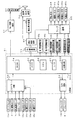
図2は、主基板(遊技制御基板)31における回路構成の一例を示すブロック図である。なお、図2は、払出制御基板37および演出制御基板80等も示されている。主基板31には、プログラムに従ってパチンコ遊技機1を制御する遊技制御用マイクロコンピュータ(遊技制御手段に相当)560が搭載されている。遊技制御用マイクロコンピュータ560は、ゲーム制御(遊技進行制御)用のプログラム等を記憶するROM54、ワークメモリとして使用される記憶手段としてのRAM55、プログラムに従って制御動作を行うCPU56およびI/Oポート部57を含む。この実施の形態では、ROM54およびRAM55は遊技制御用マイクロコンピュータ560に内蔵されている。すなわち、遊技制御用マイクロコンピュータ560は、1チップマイクロコンピュータである。1チップマイクロコンピュータには、少なくともCPU56のほかRAM55が内蔵されていればよく、ROM54は外付けであっても内蔵されていてもよい。また、I/Oポート部57は、外付けであってもよい。遊技制御用マイクロコンピュータ560には、さらに、ハードウェア乱数(ハードウェア回路が発生する乱数)を発生する乱数回路503が内蔵されている。
FIG. 2 is a block diagram showing an example of the circuit configuration of the main board (game control board) 31. FIG. 2 also shows a
また、RAM55は、その一部または全部が電源基板910において作成されるバックアップ電源によってバックアップされている不揮発性記憶手段としてのバックアップRAMである。すなわち、遊技機に対する電力供給が停止しても、所定期間(バックアップ電源としてのコンデンサが放電してバックアップ電源が電力供給不能になるまで)は、RAM55の一部または全部の内容は保存される。特に、少なくとも、遊技状態すなわち遊技制御手段の制御状態に応じたデータ(特別図柄プロセスフラグなど)と未払出賞球数を示すデータは、バックアップRAMに保存される。遊技制御手段の制御状態に応じたデータとは、停電等が生じた後に復旧した場合に、そのデータにもとづいて、制御状態を停電等の発生前に復旧させるために必要なデータである。また、制御状態に応じたデータは、遊技の進行状態を示すデータに相当する。なお、この実施の形態では、RAM55の全部が、電源バックアップされているとする。
The
なお、遊技制御用マイクロコンピュータ560においてCPU56がROM54に格納されているプログラムに従って制御を実行するので、以下、遊技制御用マイクロコンピュータ560(またはCPU56)が実行する(または、処理を行う)ということは、具体的には、CPU56がプログラムに従って制御を実行することである。このことは、主基板31以外の他の基板に搭載されているマイクロコンピュータについても同様である。
In the
乱数回路503は、特別図柄の可変表示の表示結果により大当りとするか否か判定するための判定用の乱数を発生するために用いられるハードウェア回路である。乱数回路503は、初期値(例えば、0)と上限値(例えば、65535)とが設定された数値範囲内で、数値データを、設定された更新規則に従って更新する乱数発生機能を有する。そして、読出される数値データが乱数値として使用される。 The random number circuit 503 is a hardware circuit that is used to generate a random number for determination to determine whether or not to win a jackpot based on a display result of variable symbol special display. The random number circuit 503 has a random number generation function for updating numerical data according to a set update rule within a numerical range in which an initial value (for example, 0) and an upper limit value (for example, 65535) are set. The read numerical data is used as a random value.
乱数回路503は、数値データの更新範囲の選択設定機能(初期値の選択設定機能、および、上限値の選択設定機能)、数値データの更新規則の選択設定機能、および数値データの更新規則の選択切換え機能等の各種の機能を有する。このような機能によって、生成する乱数のランダム性を向上させることができる。 The random number circuit 503 includes a numeric data update range selection setting function (initial value selection setting function and upper limit value selection setting function), numeric data update rule selection setting function, and numeric data update rule selection. It has various functions such as a switching function. With such a function, the randomness of the generated random numbers can be improved.
また、遊技制御用マイクロコンピュータ560は、乱数回路503が更新する数値データの初期値を設定する機能を有している。例えば、ROM54等の所定の記憶領域に記憶された遊技制御用マイクロコンピュータ560のIDナンバ(遊技制御用マイクロコンピュータ560の各製品ごとに異なる数値で付与されたIDナンバ)を用いて所定の演算を行なって得られた数値データを、乱数回路503が更新する数値データの初期値として設定する。そのような処理を行うことによって、乱数回路503が発生する乱数のランダム性をより向上させることができる。
Further, the
また、ゲートスイッチ32a、始動口スイッチ13a、カウントスイッチ23、入賞口スイッチ29a,30a,33a,39aからの検出信号を遊技制御用マイクロコンピュータ560に与える入力ドライバ回路58も主基板31に搭載されている。また、可変入賞球装置15を開閉するソレノイド16、および大入賞口を形成する特別可変入賞球装置20を開閉するソレノイド21を遊技制御用マイクロコンピュータ560からの指令に従って駆動する出力回路59も主基板31に搭載されている。
Further, an
また、遊技制御用マイクロコンピュータ560は、特別図柄を可変表示する第1特別図柄表示器8a、第2特別図柄表示器8b、普通図柄を可変表示する普通図柄表示器10、第1特別図柄保留記憶表示器18a、第2特別図柄保留記憶表示器18bおよび普通図柄保留記憶表示器41の表示制御を行う。
In addition, the
なお、大当り遊技状態の発生を示す大当り情報等の情報出力信号をホールコンピュータ等の外部装置に対して出力する情報出力回路(図示せず)も主基板31に搭載されている。
An information output circuit (not shown) that outputs an information output signal such as jackpot information indicating the occurrence of a jackpot gaming state to an external device such as a hall computer is also mounted on the
この実施の形態では、演出制御基板80に搭載されている演出制御手段(演出制御用マイクロコンピュータで構成される。)が、中継基板77を介して遊技制御用マイクロコンピュータ560から演出内容を指示する演出制御コマンドを受信し、飾り図柄を可変表示する演出表示装置9の表示制御を行う。
In this embodiment, the effect control means (configured by the effect control microcomputer) mounted on the
また、演出制御基板80に搭載されている演出制御手段が、ランプドライバ基板35を介して、遊技盤に設けられている装飾LED25、および枠側に設けられている枠LED28の表示制御を行うとともに、音声出力基板70を介してスピーカ27からの音出力の制御を行う。
In addition, the effect control means mounted on the
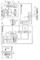
図3は、中継基板77、演出制御基板80、ランプドライバ基板35および音声出力基板70の回路構成例を示すブロック図である。なお、図3に示す例では、ランプドライバ基板35および音声出力基板70には、マイクロコンピュータは搭載されていないが、マイクロコンピュータを搭載してもよい。また、ランプドライバ基板35および音声出力基板70を設けずに、演出制御に関して演出制御基板80のみを設けてもよい。
FIG. 3 is a block diagram illustrating a circuit configuration example of the
演出制御基板80は、演出制御用CPU101、および飾り図柄プロセスフラグ等の演出に関する情報を記憶するRAMを含む演出制御用マイクロコンピュータ100を搭載している。なお、RAMは外付けであってもよい。この実施の形態では、演出制御用マイクロコンピュータ100におけるRAMは電源バックアップされていない。演出制御基板80において、演出制御用CPU101は、内蔵または外付けのROM(図示せず)に格納されたプログラムに従って動作し、中継基板77を介して入力される主基板31からの取込信号(演出制御INT信号)に応じて、入力ドライバ102および入力ポート103を介して演出制御コマンドを受信する。また、演出制御用CPU101は、演出制御コマンドにもとづいて、VDP(ビデオディスプレイプロセッサ)109に演出表示装置9の表示制御を行わせる。
The
この実施の形態では、演出制御用マイクロコンピュータ100と共動して演出表示装置9の表示制御を行うVDP109が演出制御基板80に搭載されている。VDP109は、演出制御用マイクロコンピュータ100とは独立したアドレス空間を有し、そこにVRAMをマッピングする。VRAMは、画像データを展開するためのバッファメモリである。そして、VDP109は、VRAM内の画像データをフレームメモリを介して演出表示装置9に出力する。
In this embodiment, a
なお、演出表示装置9として、液晶表示装置が用いられている。液晶表示装置はバックライト91(液晶表示パネルの背面に設置されているものに限られず、側面に設置されているものも含む概念)を含む。
Note that a liquid crystal display device is used as the
演出制御用CPU101は、受信した演出制御コマンドに従ってCGROM(図示せず)から必要なデータを読み出すための指令をVDP109に出力する。CGROMは、演出表示装置9に表示されるキャラクタ画像データや動画像データ、具体的には、人物、文字、図形や記号等(飾り図柄を含む)、および背景画像のデータをあらかじめ格納しておくためのROMである。VDP109は、演出制御用CPU101の指令に応じて、CGROMから画像データを読み出す。そして、VDP109は、読み出した画像データにもとづいて表示制御を実行する。
The effect control CPU 101 outputs to the VDP 109 a command for reading out necessary data from a CGROM (not shown) in accordance with the received effect control command. The CGROM stores in advance character image data and moving image data to be displayed on the
演出制御コマンドおよび演出制御INT信号は、演出制御基板80において、まず、入力ドライバ102に入力する。入力ドライバ102は、中継基板77から入力された信号を演出制御基板80の内部に向かう方向にしか通過させない(演出制御基板80の内部から中継基板77への方向には信号を通過させない)信号方向規制手段としての単方向性回路でもある。
The effect control command and the effect control INT signal are first input to the
中継基板77には、主基板31から入力された信号を演出制御基板80に向かう方向にしか通過させない(演出制御基板80から中継基板77への方向には信号を通過させない)信号方向規制手段としての単方向性回路74が搭載されている。単方向性回路として、例えばダイオードやトランジスタが使用される。図3には、ダイオードが例示されている。また、単方向性回路は、各信号毎に設けられる。さらに、単方向性回路である出力ポート571を介して主基板31から演出制御コマンドおよび演出制御INT信号が出力されるので、中継基板77から主基板31の内部に向かう信号が規制される。すなわち、中継基板77からの信号は主基板31の内部(遊技制御用マイクロコンピュータ560側)に入り込まない。なお、出力ポート571は、図2に示されたI/Oポート部57の一部である。また、出力ポート571の外側(中継基板77側)に、さらに、単方向性回路である信号ドライバ回路が設けられていてもよい。
As a signal direction regulating means, the signal inputted from the
さらに、演出制御用CPU101は、出力ポート105を介してランプドライバ基板35に対してLEDを駆動する信号を出力する。また、演出制御用CPU101は、出力ポート104を介して音声出力基板70に対して音番号データを出力する。
Further, the effect control CPU 101 outputs a signal for driving the LED to the
ランプドライバ基板35において、LEDを駆動する信号は、入力ドライバ351を介してLEDドライバ352に入力される。LEDドライバ352は、LEDを駆動する信号にもとづいて枠LED28などの枠側に設けられている発光体に電流を供給する。また、遊技盤側に設けられている装飾LED25に電流を供給する。
In the
音声出力基板70において、音番号データは、入力ドライバ702を介して音声合成用IC703に入力される。音声合成用IC703は、音番号データに応じた音声や効果音を発生し増幅回路705に出力する。増幅回路705は、音声合成用IC703の出力レベルを、ボリューム706で設定されている音量に応じたレベルに増幅した音声信号をスピーカ27に出力する。音声データROM704には、音番号データに応じた制御データが格納されている。音番号データに応じた制御データは、所定期間(例えば飾り図柄の変動期間)における効果音または音声の出力態様を時系列的に示すデータの集まりである。
In the
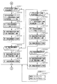
次に、遊技機の動作について説明する。図4は、主基板31における遊技制御用マイクロコンピュータ560が実行するメイン処理を示すフローチャートである。遊技機に対して電源が投入され電力供給が開始されると、リセット信号が入力されるリセット端子の入力レベルがハイレベルになり、遊技制御用マイクロコンピュータ560(具体的には、CPU56)は、プログラムの内容が正当か否か確認するための処理であるセキュリティチェック処理を実行した後、ステップS1以降のメイン処理を開始する。メイン処理において、CPU56は、まず、必要な初期設定を行う。
Next, the operation of the gaming machine will be described. FIG. 4 is a flowchart showing a main process executed by the
初期設定処理において、CPU56は、まず、割込禁止に設定する(ステップS1)。次に、割込モードを割込モード2に設定し(ステップS2)、スタックポインタにスタックポインタ指定アドレスを設定する(ステップS3)。そして、内蔵デバイスの初期化(内蔵デバイス(内蔵周辺回路)であるCTC(カウンタ/タイマ)およびPIO(パラレル入出力ポート)の初期化など)を行った後(ステップS4)、RAMをアクセス可能状態に設定する(ステップS5)。なお、割込モード2は、CPU56が内蔵する特定レジスタ(Iレジスタ)の値(1バイト)と内蔵デバイスが出力する割込ベクタ(1バイト:最下位ビット0)とから合成されるアドレスが、割込番地を示すモードである。
In the initial setting process, the
次いで、CPU56は、入力ポートを介して入力されるクリアスイッチ(例えば、電源基板に搭載されている。)の出力信号(クリア信号)の状態を確認する(ステップS6)。その確認においてオンを検出した場合には、CPU56は、通常の初期化処理(ステップS10〜S15)を実行する。
Next, the
クリアスイッチがオンの状態でない場合には、遊技機への電力供給が停止したときにバックアップRAM領域のデータ保護処理(例えばパリティデータの付加等の電力供給停止時処理)が行われたか否か確認する(ステップS7)。そのような保護処理が行われていないことを確認したら、CPU56は初期化処理を実行する。バックアップRAM領域にバックアップデータがあるか否かは、例えば、電力供給停止時処理においてバックアップRAM領域に設定されるバックアップフラグの状態によって確認される。
If the clear switch is not on, check whether data protection processing of the backup RAM area (for example, power supply stop processing such as addition of parity data) was performed when power supply to the gaming machine was stopped (Step S7). When it is confirmed that such protection processing is not performed, the
電力供給停止時処理が行われたことを確認したら、CPU56は、バックアップRAM領域のデータチェックを行う(ステップS8)。この実施の形態では、データチェックとしてパリティチェックを行う。よって、ステップS8では、算出したチェックサムと、電力供給停止時処理で同一の処理によって算出され保存されているチェックサムとを比較する。不測の停電等の電力供給停止が生じた後に復旧した場合には、バックアップRAM領域のデータは保存されているはずであるから、チェック結果(比較結果)は正常(一致)になる。チェック結果が正常でないということは、バックアップRAM領域のデータが、電力供給停止時のデータとは異なっていることを意味する。そのような場合には、内部状態を電力供給停止時の状態に戻すことができないので、電力供給の停止からの復旧時でない電源投入時に実行される初期化処理を実行する。
When it is confirmed that the power supply stop process has been performed, the
チェック結果が正常であれば、CPU56は、遊技制御手段の内部状態と演出制御手段等の電気部品制御手段の制御状態を電力供給停止時の状態に戻すための遊技状態復旧処理(ステップS41〜S43の処理)を行う。具体的には、ROM54に格納されているバックアップ時設定テーブルの先頭アドレスをポインタに設定し(ステップS41)、バックアップ時設定テーブルの内容を順次作業領域(RAM55内の領域)に設定する(ステップS42)。作業領域はバックアップ電源によって電源バックアップされている。バックアップ時設定テーブルには、作業領域のうち初期化してもよい領域についての初期化データが設定されている。ステップS41およびS42の処理によって、作業領域のうち初期化してはならない部分については、保存されていた内容がそのまま残る。初期化してはならない部分とは、例えば、電力供給停止前の遊技状態を示すデータ(特別図柄プロセスフラグ、確変フラグ、時短フラグなど)、出力ポートの出力状態が保存されている領域(出力ポートバッファ)、未払出賞球数を示すデータが設定されている部分などである。
If the check result is normal, the
また、CPU56は、電力供給復旧時の初期化コマンドとしての停電復旧指定コマンドを送信する(ステップS43)。そして、ステップS14に移行する。
Further, the
なお、この実施の形態では、バックアップフラグとチェックデータとの双方を用いてバックアップRAM領域のデータが保存されているか否か確認しているが、いずれか一方のみを用いてもよい。すなわち、バックアップフラグとチェックデータとのいずれかを、遊技状態復旧処理を実行するための契機としてもよい。 In this embodiment, it is confirmed whether the data in the backup RAM area is stored using both the backup flag and the check data. However, only one of them may be used. That is, either the backup flag or the check data may be used as an opportunity for executing the game state restoration process.
初期化処理では、CPU56は、まず、RAMクリア処理を行う(ステップS10)。なお、RAMクリア処理によって、所定のデータ(例えば、普通図柄当り判定用乱数を生成するためのカウンタのカウント値のデータ)は0に初期化されるが、任意の値またはあらかじめ決められている値に初期化するようにしてもよい。また、RAM55の全領域を初期化せず、所定のデータ(例えば、普通図柄当り判定用乱数を生成するためのカウンタのカウント値のデータ)をそのままにしてもよい。また、ROM54に格納されている初期化時設定テーブルの先頭アドレスをポインタに設定し(ステップS11)、初期化時設定テーブルの内容を順次作業領域に設定する(ステップS12)。
In the initialization process, the
ステップS11およびS12の処理によって、例えば、普通図柄当り判定用乱数カウンタ、特別図柄バッファ、総賞球数格納バッファ、特別図柄プロセスフラグなど制御状態に応じて選択的に処理を行うためのフラグに初期値が設定される。 By the processing in steps S11 and S12, for example, a normal symbol per-determining random number counter, a special symbol buffer, a total prize ball number storage buffer, a special symbol process flag, and other flags for selectively performing processing according to the control state are initialized. Value is set.
また、CPU56は、サブ基板(主基板31以外のマイクロコンピュータが搭載された基板。)を初期化するための初期化指定コマンド(遊技制御用マイクロコンピュータ560が初期化処理を実行したことを示すコマンドでもある。)をサブ基板に送信する(ステップS13)。例えば、演出制御用マイクロコンピュータ100は、初期化指定コマンドを受信すると、演出表示装置9において、遊技機の制御の初期化がなされたことを報知するための画面表示、すなわち初期化報知を行う。
Further, the
また、CPU56は、乱数回路503を初期設定する乱数回路設定処理を実行する(ステップS14)。CPU56は、例えば、乱数回路設定プログラムに従って処理を実行することによって、乱数回路503にランダムRの値を更新させるための設定を行う。
Further, the
そして、ステップS15において、CPU56は、所定時間(例えば4ms)毎に定期的にタイマ割込がかかるように遊技制御用マイクロコンピュータ560に内蔵されているCTCのレジスタの設定を行なう。すなわち、初期値として例えば4msに相当する値が所定のレジスタ(時間定数レジスタ)に設定される。この実施の形態では、4ms毎に定期的にタイマ割込がかかるとする。
In step S15, the
初期化処理の実行(ステップS10〜S15)が完了すると、CPU56は、メイン処理で、表示用乱数更新処理(ステップS17)および初期値用乱数更新処理(ステップS18)を繰り返し実行する。表示用乱数更新処理および初期値用乱数更新処理を実行するときには割込禁止状態に設定し(ステップS16)、表示用乱数更新処理および初期値用乱数更新処理の実行が終了すると割込許可状態に設定する(ステップS19)。この実施の形態では、表示用乱数とは、変動パターンの種別を決定するための乱数や変動パターンを決定するための乱数であり、表示用乱数更新処理とは、表示用乱数を発生するためのカウンタのカウント値を更新する処理である。また、初期値用乱数更新処理とは、初期値用乱数を発生するためのカウンタのカウント値を更新する処理である。この実施の形態では、初期値用乱数とは、普通図柄に関して当りとするか否か決定するための乱数を発生するためのカウンタ(普通図柄当り判定用乱数発生カウンタ)のカウント値の初期値を決定するための乱数である。後述する遊技の進行を制御する遊技制御処理(遊技制御用マイクロコンピュータ560が、遊技機に設けられている演出表示装置、可変入賞球装置、球払出装置等の遊技用の装置を、自身で制御する処理、または他のマイクロコンピュータに制御させるために指令信号を送信する処理、遊技装置制御処理ともいう)において、普通図柄当り判定用乱数のカウント値が1周(普通図柄当り判定用乱数の取りうる値の最小値から最大値までの間の数値の個数分歩進したこと)すると、そのカウンタに初期値が設定される。
When the execution of the initialization process (steps S10 to S15) is completed, the
なお、この実施の形態では、リーチ演出は、演出表示装置9において可変表示される飾り図柄を用いて実行される。また、特別図柄の表示結果を大当り図柄にする場合には、リーチ演出は常に実行される。特別図柄の表示結果を大当り図柄にしない場合には、遊技制御用マイクロコンピュータ560は、乱数を用いた抽選によって、リーチ演出を実行するか否か決定する。ただし、実際にリーチ演出の制御を実行するのは、演出制御用マイクロコンピュータ100である。
In this embodiment, the reach effect is executed using a decorative symbol variably displayed on the
タイマ割込が発生すると、CPU56は、図5に示すステップS20〜S34のタイマ割込処理を実行する。タイマ割込処理において、まず、電源断信号が出力されたか否か(オン状態になったか否か)を検出する電源断検出処理を実行する(ステップS20)。電源断信号は、例えば電源基板に搭載されている電源監視回路が、遊技機に供給される電源の電圧の低下を検出した場合に出力する。そして、電源断検出処理において、CPU56は、電源断信号が出力されたことを検出したら、必要なデータをバックアップRAM領域に保存するための電力供給停止時処理を実行する。次いで、入力ドライバ回路58を介して、ゲートスイッチ32a、第1始動口スイッチ13a、第2始動口スイッチ14aおよびカウントスイッチ23の検出信号を入力し、それらの状態判定を行う(スイッチ処理:ステップS21)。
When the timer interrupt occurs, the
次に、CPU56は、第1特別図柄表示器8a、第2特別図柄表示器8b、普通図柄表示器10、第1特別図柄保留記憶表示器18a、第2特別図柄保留記憶表示器18b、普通図柄保留記憶表示器41の表示制御を行う表示制御処理を実行する(ステップS22)。第1特別図柄表示器8a、第2特別図柄表示器8bおよび普通図柄表示器10については、ステップS32,S33で設定される出力バッファの内容に応じて各表示器に対して駆動信号を出力する制御を実行する。
Next, the
また、遊技制御に用いられる普通図柄当り判定用乱数等の各判定用乱数を生成するための各カウンタのカウント値を更新する処理を行う(判定用乱数更新処理:ステップS23)。CPU56は、さらに、初期値用乱数および表示用乱数を生成するためのカウンタのカウント値を更新する処理を行う(初期値用乱数更新処理,表示用乱数更新処理:ステップS24,S25)。
Also, a process of updating the count value of each counter for generating each random number for determination such as a random number for determination per ordinary symbol used for game control is performed (determination random number update process: step S23). The
さらに、CPU56は、特別図柄プロセス処理を行う(ステップS26)。特別図柄プロセス処理では、第1特別図柄表示器8a、第2特別図柄表示器8bおよび大入賞口を所定の順序で制御するための特別図柄プロセスフラグに従って該当する処理を実行する。CPU56は、特別図柄プロセスフラグの値を、遊技状態に応じて更新する。
Further, the
次いで、普通図柄プロセス処理を行う(ステップS27)。普通図柄プロセス処理では、CPU56は、普通図柄表示器10の表示状態を所定の順序で制御するための普通図柄プロセスフラグに従って該当する処理を実行する。CPU56は、普通図柄プロセスフラグの値を、遊技状態に応じて更新する。
Next, normal symbol process processing is performed (step S27). In the normal symbol process, the
また、CPU56は、演出制御用マイクロコンピュータ100に演出制御コマンドを送出する処理を行う(演出制御コマンド制御処理:ステップS28)。
Further, the
さらに、CPU56は、例えばホール管理用コンピュータに供給される大当り情報、始動情報、確率変動情報などのデータを出力する情報出力処理を行う(ステップS29)。
Further, the
また、CPU56は、第1始動口スイッチ13a、第2始動口スイッチ14aおよびカウントスイッチ23の検出信号にもとづく賞球個数の設定などを行う賞球処理を実行する(ステップS30)。具体的には、第1始動口スイッチ13a、第2始動口スイッチ14aおよびカウントスイッチ23のいずれかがオンしたことにもとづく入賞検出に応じて、払出制御基板37に搭載されている払出制御用マイクロコンピュータに賞球個数を示す払出制御コマンド(賞球個数信号)を出力する。払出制御用マイクロコンピュータは、賞球個数を示す払出制御コマンドに応じて球払出装置97を駆動する。
Further, the
この実施の形態では、出力ポートの出力状態に対応したRAM領域(出力ポートバッファ)が設けられているのであるが、CPU56は、出力ポートの出力状態に対応したRAM領域におけるソレノイドのオン/オフに関する内容を出力ポートに出力する(ステップS31:出力処理)。
In this embodiment, a RAM area (output port buffer) corresponding to the output state of the output port is provided. However, the
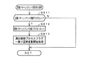
また、CPU56は、特別図柄プロセスフラグの値に応じて特別図柄の演出表示を行うための特別図柄表示制御データを特別図柄表示制御データ設定用の出力バッファに設定する特別図柄表示制御処理を行う(ステップS32)。
Further, the
さらに、CPU56は、普通図柄プロセスフラグの値に応じて普通図柄の演出表示を行うための普通図柄表示制御データを普通図柄表示制御データ設定用の出力バッファに設定する普通図柄表示制御処理を行う(ステップS33)。CPU56は、例えば、普通図柄の変動に関する開始フラグがセットされると終了フラグがセットされるまで、普通図柄の変動速度が0.2秒ごとに表示状態(「○」および「×」)を切り替えるような速度であれば、0.2秒が経過する毎に、出力バッファに設定される表示制御データの値(例えば、「○」を示す1と「×」を示す0)を切り替える。また、CPU56は、出力バッファに設定された表示制御データに応じて、ステップS22において駆動信号を出力することによって、普通図柄表示器10における普通図柄の演出表示を実行する。
Further, the
その後、割込許可状態に設定し(ステップS34)、処理を終了する。 Thereafter, the interrupt permission state is set (step S34), and the process is terminated.
以上の制御によって、この実施の形態では、遊技制御処理は4ms毎に起動されることになる。なお、遊技制御処理は、タイマ割込処理におけるステップS21〜S33(ステップS29を除く。)の処理に相当する。また、この実施の形態では、タイマ割込処理で遊技制御処理が実行されているが、タイマ割込処理では例えば割込が発生したことを示すフラグのセットのみがなされ、遊技制御処理はメイン処理において実行されるようにしてもよい。 With the above control, in this embodiment, the game control process is started every 4 ms. The game control process corresponds to the processes in steps S21 to S33 (excluding step S29) in the timer interrupt process. In this embodiment, the game control process is executed by the timer interrupt process. However, in the timer interrupt process, for example, only a flag indicating that an interrupt has occurred is set, and the game control process is performed by the main process. May be executed.
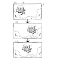
第1特別図柄表示器8aまたは第2特別図柄表示器8bおよび演出表示装置9にはずれ図柄が停止表示される場合には、飾り図柄の可変表示が開始されてから、飾り図柄の可変表示状態がリーチ状態にならずに、リーチにならない所定の飾り図柄の組み合わせが停止表示されることがある。このような飾り図柄の可変表示態様を、可変表示結果がはずれ図柄になる場合における「非リーチ」(「通常はずれ」ともいう)の可変表示態様という。
When the shifted symbol is stopped and displayed on the first
第1特別図柄表示器8aまたは第2特別図柄表示器8bおよび演出表示装置9にはずれ図柄が停止表示される場合には、飾り図柄の可変表示が開始されてから、飾り図柄の可変表示状態がリーチ状態となった後にリーチ演出が実行され、最終的に大当り図柄とはならない所定の飾り図柄の組み合わせが停止表示されることがある。このような飾り図柄の可変表示結果を、可変表示結果が「はずれ」になる場合における「リーチ」(「リーチはずれ」ともいう)の可変表示態様という。
When the shifted symbol is stopped and displayed on the first
この実施の形態では、第1特別図柄表示器8aまたは第2特別図柄表示器8bに大当り図柄が停止表示される場合には、飾り図柄の可変表示状態がリーチ状態になった後にリーチ演出が実行され、最終的に演出表示装置9における「左」、「中」、「右」の各図柄表示エリアに、飾り図柄が揃って停止表示される。
In this embodiment, when the big hit symbol is stopped and displayed on the first
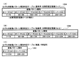
図6は、あらかじめ用意された飾り図柄の変動パターンを示す説明図である。図6に示すように、この実施の形態では、可変表示結果が「はずれ」であり飾り図柄の可変表示態様が「非リーチ」である場合に対応した変動パターンとして、非リーチPA1−1〜非リーチPA1−4の変動パターンが用意されている。また、可変表示結果が「はずれ」であり飾り図柄の可変表示態様が「リーチ」である場合に対応した変動パターンとして、ノーマルPA2−1〜ノーマルPA2−2、ノーマルPB2−1〜ノーマルPB2−2、スーパーPA3−1〜スーパーPA3−2、スーパーPB3−1〜スーパーPB3−2の変動パターンが用意されている。なお、図6に示すように、リーチしない場合に使用され擬似連の演出を伴う非リーチPA1−4の変動パターンについては、再変動が1回行われる。「擬似連」は、全ての図柄表示エリアにおいて飾り図柄を仮停止表示させた後、全ての図柄表示エリアにおいて飾り図柄を再び変動(擬似連変動)させる演出表示を、所定回行う変動パターンである。 FIG. 6 is an explanatory diagram showing a variation pattern of decorative symbols prepared in advance. As shown in FIG. 6, in this embodiment, the non-reach PA 1-1 to the non-reach pattern are used as the variation patterns corresponding to the case where the variable display result is “out of” and the decorative symbol variable display mode is “non-reach”. A variation pattern of reach PA1-4 is prepared. Further, normal PA2-1 to normal PA2-2, normal PB2-1 to normal PB2-2 are variations patterns corresponding to the case where the variable display result is “out” and the decorative symbol variable display mode is “reach”. Fluctuation patterns of Super PA3-1 to Super PA3-2 and Super PB3-1 to Super PB3-2 are prepared. Note that, as shown in FIG. 6, re-variation is performed once for the variation pattern of the non-reach PA 1-4 that is used in the case where the reach is not performed and is accompanied by a pseudo-continuous effect. The “pseudo-continuous” is a variation pattern in which an effect display is performed a predetermined number of times after the decorative symbols are temporarily stopped and displayed in all symbol display areas, and then the decorative symbols are changed again (pseudo-continuous variation) in all symbol display areas. .
リーチする場合に使用され擬似連の演出を伴う変動パターンのうち、ノーマルPB2−1を用いる場合には、再変動が1回行われる。また、リーチする場合に使用され擬似連の演出を伴う変動パターンのうち、ノーマルPB2−2を用いる場合には、再変動が2回行われる。さらに、リーチする場合に使用され擬似連の演出を伴う変動パターンのうち、スーパーPA3−1〜スーパーPA3−2を用いる場合には、再変動が3回行われる。なお、再変動とは、飾り図柄の可変表示が開始されてから表示結果が導出表示されるまでに一旦はずれになる飾り図柄を仮停止させた後に飾り図柄の可変表示を再度実行することである。 Of the variation patterns used for reaching and accompanied by pseudo-rendition, when normal PB2-1 is used, re-variation is performed once. Of the variation patterns that are used for reaching and have a pseudo-continuous effect, when normal PB2-2 is used, re-variation is performed twice. Furthermore, when using super PA3-1 to super PA3-2 among the fluctuation patterns used for reaching and accompanied by pseudo-rendition effects, re-variation is performed three times. Note that the re-variation is to temporarily execute the variable display of the decorative symbol after temporarily stopping the decorative symbol that is temporarily off from the start of the variable display of the decorative symbol until the display result is derived and displayed. .
また、図6に示すように、この実施の形態では、特別図柄の可変表示結果が大当り図柄になる場合に対応した変動パターンとして、ノーマルPA2−3〜ノーマルPA2−4、ノーマルPB2−3〜ノーマルPB2−4、スーパーPA3−3〜スーパーPA3−4、スーパーPB3−3〜スーパーPB3−4の変動パターンが用意されている。図6に示すように、擬似連の演出を伴う変動パターンのうち、ノーマルPB2−3を用いる場合には、再変動が1回行われる。また、リーチする場合に使用され擬似連の演出を伴う変動パターンのうち、ノーマルPB2−4を用いる場合には、再変動が2回行われる。さらに、リーチする場合に使用され擬似連の演出を伴う変動パターンのうち、スーパーPA3−3〜スーパーPA3−4を用いる場合には、再変動が3回行われる。 Also, as shown in FIG. 6, in this embodiment, normal PA2-3 to normal PA2-4, normal PB2-3 to normal P22-3 as normal patterns corresponding to the case where the variable symbol display result of the special symbol is a big hit symbol. Variation patterns of PB2-4, super PA3-3 to super PA3-4, super PB3-3 to super PB3-4 are prepared. As shown in FIG. 6, when the normal PB2-3 is used among the fluctuation patterns accompanied by the pseudo-continuous effects, the re-variation is performed once. Of the fluctuation patterns used for reaching and accompanied by pseudo-continuous effects, when normal PB2-4 is used, re-variation is performed twice. Furthermore, when using super PA3-3 to super PA3-4 among the fluctuation patterns that are used for reaching and have the effect of pseudo-ream, re-variation is performed three times.
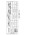
なお、この実施の形態では、図6に示すように、リーチの種類に応じて変動時間が固定的に定められている場合(例えば、擬似連ありのスーパーリーチAの場合には変動時間が32.75秒で固定であり、擬似連なしのスーパーリーチAの場合には変動時間が22.75秒で固定である。)を示しているが、例えば、同じ種類のスーパーリーチの場合であっても、合算保留記憶数に応じて、変動時間を異ならせるようにしてもよい。例えば、同じ種類のスーパーリーチを伴う場合であっても、合算保留記憶数が多くなるに従って、変動時間が短くなるようにしてもよい。また、例えば、同じ種類のスーパーリーチの場合であっても、第1特別図柄の変動表示を行う場合には、第1保留記憶数に応じて、変動時間を異ならせるようにしてもよく、第2特別図柄の変動表示を行う場合には、第2保留記憶数に応じて、変動時間を異ならせるようにしてもよい。この場合、第1保留記憶数や第2保留記憶数の値ごとに別々の判定テーブルを用意しておき(例えば、保留記憶数0〜2用の変動パターン種別判定テーブルと保留記憶数3,4用の変動パターン種別判定テーブルとを用意しておき)、第1保留記憶数または第2保留記憶数の値に応じて判定テーブルを選択して、変動時間を異ならせるようにしてもよい。
In this embodiment, as shown in FIG. 6, when the variation time is fixedly determined according to the type of reach (for example, the variation time is 32 in the case of Super Reach A with pseudo-ream). In the case of Super Reach A without pseudo-ream, the fluctuation time is fixed at 22.75 seconds.) For example, in the case of the same type of super reach Alternatively, the variation time may be varied according to the total number of pending storage. For example, even with the same type of super reach, the variation time may be shortened as the total number of pending storage increases. Also, for example, even in the case of the same type of super reach, when the variable display of the first special symbol is performed, the variable time may be varied according to the first reserved memory number. When the variable display of the two special symbols is performed, the variable time may be varied according to the second reserved memory number. In this case, a separate determination table is prepared for each value of the first reserved memory number and the second reserved memory number (for example, the variation pattern type determination table for the
図7は、各乱数を示す説明図である。各乱数は、以下のように使用される。
(1)ランダム1:大当りの種類(通常大当り、確変大当り)を決定する(大当り種別判定用)
(2)ランダム2:変動パターンの種類(種別)を決定する(変動パターン種別判定用)
(3)ランダム3:変動パターン(変動時間)を決定する(変動パターン判定用)
(4)ランダム4:普通図柄にもとづく当りを発生させるか否か決定する(普通図柄当り判定用)
(5)ランダム5:ランダム4の初期値を決定する(ランダム4初期値決定用)
FIG. 7 is an explanatory diagram showing each random number. Each random number is used as follows.
(1) Random 1: Determine the type of jackpot (normal jackpot, probability variation jackpot) (for jackpot type judgment)
(2) Random 2: Determines the type (classification) of the variation pattern (for variation pattern type determination)
(3) Random 3: Determine variation pattern (variation time) (for variation pattern determination)
(4) Random 4: Determines whether or not to generate a hit based on the normal symbol (for normal symbol hit determination)
(5) Random 5:
なお、この実施の形態では、変動パターンは、まず、変動パターン種別判定用乱数(ランダム2)を用いて変動パターン種別を決定し、変動パターン判定用乱数(ランダム3)を用いて、決定した変動パターン種別に含まれるいずれかの変動パターンに決定する。そのように、この実施の形態では、2段階の抽選処理によって変動パターンが決定される。 In this embodiment, the variation pattern is first determined using the variation pattern type determination random number (random 2), and then the variation pattern determined using the variation pattern determination random number (random 3). One of the variation patterns included in the pattern type is determined. Thus, in this embodiment, the variation pattern is determined by a two-stage lottery process.
なお、変動パターン種別とは、複数の変動パターンをその変動態様の特徴に従ってグループ化したものである。例えば、複数の変動パターンをリーチの種類でグループ化して、ノーマルリーチを伴う変動パターンを含む変動パターン種別と、スーパーリーチAを伴う変動パターンを含む変動パターン種別と、スーパーリーチBを伴う変動パターンを含む変動パターン種別とに分けてもよい。また、例えば、複数の変動パターンを擬似連の再変動の回数でグループ化して、擬似連を伴わない変動パターンを含む変動パターン種別と、再変動1回の変動パターンを含む変動パターン種別と、再変動2回の変動パターンを含む変動パターン種別と、再変動3回の変動パターンを含む変動パターン種別とに分けてもよい。また、例えば、複数の変動パターンを擬似連や滑り演出などの特定演出の有無でグループ化してもよい。 The variation pattern type is a group of a plurality of variation patterns according to the characteristics of the variation mode. For example, a plurality of variation patterns are grouped by reach type, and include a variation pattern type including a variation pattern with normal reach, a variation pattern type including a variation pattern with super reach A, and a variation pattern with super reach B. It may be divided into variable pattern types. Further, for example, a plurality of variation patterns are grouped by the number of re-variations of pseudo-continuations, a variation pattern type including a variation pattern without pseudo-ream, a variation pattern type including a variation pattern of one re-variation, It may be divided into a variation pattern type including a variation pattern of two variations and a variation pattern type including a variation pattern of three variations. Further, for example, a plurality of variation patterns may be grouped according to the presence / absence of a specific effect such as a pseudo ream or a slip effect.
なお、この実施の形態では、後述するように、確変大当りである場合には、ノーマルリーチのみを伴う変動パターンを含む変動パターン種別であるノーマルCA3−1と、ノーマルリーチおよび擬似連を伴う変動パターンを含む変動パターン種別であるノーマルCA3−2と、スーパーリーチを伴う変動パターン種別であるスーパーCA3−3とに種別分けされている。また、通常大当りである場合には、ノーマルリーチのみを伴う変動パターンを含む変動パターン種別であるノーマルCA3−1と、ノーマルリーチおよび擬似連を伴う変動パターンを含む変動パターン種別であるノーマルCA3−2と、スーパーリーチを伴う変動パターン種別であるスーパーCA3−3とに種別分けされている。また、はずれである場合には、リーチも特定演出も伴わない変動パターンを含む変動パターン種別である非リーチCA2−1と、リーチを伴わないが特定演出を伴う変動パターンを含む変動パターン種別である非リーチCA2−2と、リーチも特定演出も伴わない短縮変動の変動パターンを含む変動パターン種別である非リーチCA2−3と、ノーマルリーチのみを伴う変動パターンを含む変動パターン種別であるノーマルCA2−4と、ノーマルリーチおよび再変動2回の擬似連を伴う変動パターンを含む変動パターン種別であるノーマルCA2−5と、ノーマルリーチおよび再変動1回の擬似連を伴う変動パターンを含む変動パターン種別であるノーマルCA2−6と、スーパーリーチを伴う変動パターン種別であるスーパーCA2−7とに種別分けされている。 In this embodiment, as will be described later, in the case of a probable big hit, a normal CA3-1 which is a variation pattern type including a variation pattern with only normal reach, and a variation pattern with normal reach and pseudo-continuity are included. It is classified into a normal CA 3-2 that is a variation pattern type and a super CA 3-3 that is a variation pattern type with super reach. Further, in the case of a normal big hit, a normal CA3-1 that is a variation pattern type including a variation pattern with only normal reach, a normal CA3-2 that is a variation pattern type including a variation pattern with normal reach and pseudo-continuity, It is classified into Super CA3-3 which is a variation pattern type with super reach. Further, in the case of a deviation, it is a non-reach CA 2-1 that is a variation pattern type including a variation pattern with no reach and a specific effect, and a variation pattern type that includes a change pattern with a specific effect without a reach. Non-reach CA2-2, non-reach CA2-3 which is a variation pattern type including a variation pattern of shortened variation without reach and specific effects, and normal CA2-4 which is a variation pattern type including a variation pattern with only normal reach And normal CA2-5 which is a variation pattern type including a variation pattern with normal reach and two re-variation pseudo-continuations, and normal CA2 which is a variation pattern type including a variation pattern with one normal reach and one re-variation pseudo-continuation -6 and super CA2-7 which is a variation pattern type with super reach Are the type divided into.
図5に示された遊技制御処理におけるステップS23では、遊技制御用マイクロコンピュータ560は、(1)の大当り種別判定用乱数、および(4)の普通図柄当り判定用乱数を生成するためのカウンタのカウントアップ(1加算)を行う。すなわち、それらが判定用乱数であり、それら以外の乱数が表示用乱数(ランダム2、ランダム3)または初期値用乱数(ランダム5)である。なお、遊技効果を高めるために、上記の乱数以外の乱数も用いてもよい。また、この実施の形態では、大当り判定用乱数として、遊技制御用マイクロコンピュータ560に内蔵されたハードウェア(遊技制御用マイクロコンピュータ560の外部のハードウェアでもよい。)が生成する乱数を用いる。
In step S23 in the game control process shown in FIG. 5, the
図8は、大当り判定テーブルを示す説明図である。大当り判定テーブルは、ROM54に記憶されているデータの集まりであって、ランダムRと比較される大当り判定値が設定されているテーブルである。大当り判定テーブルには、通常状態(確変状態でない遊技状態)において用いられる通常時大当り判定テーブルと、確変状態において用いられる確変時大当り判定テーブルとがある。通常時大当り判定テーブルには、図8の左欄に記載されている各数値が設定され、確変時大当り判定テーブルには、図8の右欄に記載されている各数値が設定されている。図8に記載されている数値が大当り判定値である。
FIG. 8 is an explanatory diagram showing a jackpot determination table. The jackpot determination table is a collection of data stored in the
CPU56は、所定の時期に、乱数回路503のカウント値を抽出して抽出値を大当り判定用乱数(ランダムR)の値とするのであるが、大当り判定用乱数値が図8に示すいずれかの大当り判定値に一致すると、特別図柄に関して大当り(通常大当りまたは確変大当り)にすることに決定する。なお、大当りにするか否か決定するということは、大当り遊技状態に移行させるか否か決定するということであるが、第1特別図柄表示器8aまたは第2特別図柄表示器8bにおける停止図柄を大当り図柄にするか否か決定するということでもある。
The
図9は、ROM54に記憶されている大当り種別判定テーブルを示す説明図である。図9に示す大当り種別判定テーブルは、可変表示結果を大当り図柄にする旨の判定がなされたときに、大当り種別判定用の乱数(ランダム1)にもとづいて、大当りの種別を「確変大当り」と「非確変大当り」(通常大当り)とのうちのいずれかに決定するために参照されるテーブルである。
FIG. 9 is an explanatory diagram showing a jackpot type determination table stored in the
なお、この実施の形態では所定の乱数を用いて大当りの種別を決定するが、所定の乱数を用いて特別図柄の停止図柄を決定し、決定された特別図柄の種別に応じて大当りの種別が決まるようにしてもよい。一例として、大当り図柄を決定する場合の大当り図柄判定テーブルを設け、大当り図柄のそれぞれに対応する判定値を設定する。CPU56は、所定の乱数と大当り図柄判定テーブルとを用いて、大当り図柄を決定する。そして、大当り種別を、決定された大当り図柄に応じた種別にする。
In this embodiment, the jackpot type is determined using a predetermined random number, but the stop pattern of the special symbol is determined using the predetermined random number, and the jackpot type is determined according to the determined special symbol type. It may be determined. As an example, a jackpot symbol determination table for determining a jackpot symbol is provided, and a determination value corresponding to each of the jackpot symbols is set. The
なお、所定の乱数を用いて特別図柄の停止図柄を決定し、決定された特別図柄の種別に応じて大当りの種別を決定する場合に、ある図柄(1つでもよいし複数でもよい)については、そのときの遊技状態に応じて、大当り遊技の終了後に時短状態に移行させる場合があったり、時短状態に移行させない場合があったりしてもよい。 In addition, when determining a stop symbol of a special symbol using a predetermined random number and determining a jackpot type according to the determined special symbol type, for a certain symbol (one or more) Depending on the game state at that time, there may be a case where the game is shifted to the short time state after the end of the big hit game, or there is a case where it is not possible to shift to the time reduction state.
図10(A),(B)は、大当り用変動パターン種別判定テーブル132A,132Bを示す説明図である。大当り用変動パターン種別判定テーブル132A,132Bは、可変表示結果を大当り図柄にする旨の判定がなされたときに、大当り種別の判定結果に応じて、変動パターン種別を、変動パターン種別判定用の乱数(ランダム2)にもとづいて複数種類のうちのいずれかに決定するために参照されるテーブルである。 FIGS. 10A and 10B are explanatory diagrams showing the big hit variation pattern type determination tables 132A and 132B. The jackpot variation pattern type determination tables 132A and 132B, when it is determined that the variable display result is a jackpot symbol, the variation pattern type is determined according to the determination result of the jackpot type and a random number for determining the variation pattern type. It is a table that is referred to in order to determine one of a plurality of types based on (Random 2).
各大当り用変動パターン種別判定テーブル132A,132Bには、変動パターン種別判定用の乱数(ランダム2)の値と比較される数値(判定値)であって、ノーマルCA3−1〜ノーマルCA3−2、スーパーCA3−3の変動パターン種別のいずれかに対応する判定値が設定されている。 Each of the big hit variation pattern type determination tables 132A and 132B includes numerical values (determination values) to be compared with random number (random 2) values for variation pattern type determination, which are normal CA3-1 to normal CA3-2, A determination value corresponding to one of the variation pattern types of the super CA3-3 is set.
例えば、大当り種別が「通常大当り」である場合に用いられる図10(A)に示す大当り用変動パターン種別判定テーブル132Aと、大当り種別が「確変大当り」である場合に用いられる図10(B)に示す大当り用変動パターン種別判定テーブル132Bとで、ノーマルCA3−1〜ノーマルCA3−2、スーパーCA3−3の変動パターン種別に対する判定値の割り当てが異なっている。 For example, the big hit variation pattern type determination table 132A shown in FIG. 10 (A) used when the big hit type is “normal big hit” and FIG. 10 (B) used when the big hit type is “probable big hit”. The allocation of determination values for the variation pattern types of normal CA3-1 to normal CA3-2 and super CA3-3 is different from the big hit variation pattern type determination table 132B.
このように、大当り種別に応じて選択される大当り用変動パターン種別判定テーブル132A,132Bを比較すると、大当り種別に応じて各変動パターン種別に対する判定値の割り当てが異なっている。また、大当り種別に応じて異なる変動パターン種別に対して判定値が割り当てられている。よって、大当り種別を複数種類のうちのいずれにするかの決定結果に応じて、異なる変動パターン種別に決定することができ、同一の変動パターン種別に決定される割合を異ならせることができる。 As described above, when the big hit variation pattern type determination tables 132A and 132B selected according to the big hit type are compared, the assignment of the determination value to each fluctuation pattern type is different according to the big hit type. Also, determination values are assigned to different variation pattern types depending on the jackpot type. Therefore, different variation pattern types can be determined according to the determination result of whether the big hit type is a plurality of types, and the ratio determined for the same variation pattern type can be varied.
なお、図10(A),(B)に示すように、この実施の形態では、通常大当りまたは確変大当りである場合に、変動パターン種別判定用の乱数(ランダム2)の値が150〜251であれば、少なくともスーパーリーチ(スーパーリーチA、スーパーリーチB)を伴う変動表示が実行される。 As shown in FIGS. 10A and 10B, in this embodiment, the random number (random 2) for determining the variation pattern type is 150 to 251 in the case of a normal big hit or a probable big hit. If there is, a variable display accompanied by at least super reach (super reach A, super reach B) is executed.
また、スーパーリーチ大当りについて、擬似連を伴う変動パターン種別(スーパーPA3−3、スーパーPA3−4の変動パターンを含む変動パターン種別)と、擬似連を伴わない変動パターン種別(スーパーPB3−3、スーパーPB3−4の変動パターンを含む変動パターン種別)とに分けてもよい。この場合、通常大当り用の大当り用変動パターン種別判定テーブル132Aおよび確変大当り用の大当り用変動パターン種別判定テーブル132Bの両方において、スーパーリーチかつ擬似連を伴う変動パターン種別と、スーパーリーチかつ擬似連を伴わない変動パターン種別とが割り当てられる。 In addition, for the super reach big hit, the variation pattern type with pseudo-continuity (variation pattern type including the variation pattern of Super PA3-3 and Super PA3-4) and the variation pattern type without super-continuity (Super PB3-3, Super It may be divided into a variation pattern type including a variation pattern of PB3-4. In this case, in both the big hit variation pattern type determination table 132A for normal big hit and the big hit variation pattern type determination table 132B for probability variation big hit, the variation pattern type with super reach and pseudo-ream, super reach and pseudo ream A variation pattern type that is not accompanied is assigned.
図11(A)〜(C)は、はずれ用変動パターン種別判定テーブル135A〜135Cを示す説明図である。図11(A)には、遊技状態が通常状態であるとともに合算保留記憶数が3未満である場合に用いられるはずれ用変動パターン種別判定テーブル135Aが示されている。また、図11(B)には、遊技状態が通常状態であるとともに合算保留記憶数が3以上である場合に用いられるはずれ用変動パターン種別判定テーブル135Bが示されている。また、図11(C)には、遊技状態が確変状態または時短状態である場合に用いられるはずれ用変動パターン種別判定テーブル135Cが示されている。はずれ用変動パターン種別判定テーブル135A〜135Cは、可変表示結果をはずれ図柄にする旨の判定がなされたときに、変動パターン種別を、変動パターン種別判定用の乱数(ランダム2)にもとづいて複数種類のうちのいずれかに決定するために参照されるテーブルである。 FIGS. 11A to 11C are explanatory diagrams showing the deviation variation pattern type determination tables 135A to 135C. FIG. 11A shows a loss variation pattern type determination table 135A used when the gaming state is the normal state and the total number of pending storages is less than 3. FIG. 11B shows a loss variation pattern type determination table 135B used when the gaming state is the normal state and the total number of pending storages is 3 or more. Further, FIG. 11C shows a variation pattern type determination table 135C for loss that is used when the gaming state is the probability variation state or the time saving state. The deviation variation pattern type determination tables 135A to 135C have a plurality of variation pattern types based on a random number (random 2) for variation pattern type determination when it is determined that the variable display result is a loss symbol. It is a table that is referred to in order to determine any of the above.
なお、図11に示す例では、遊技状態が確変状態または時短状態である場合と合算保留記憶数が3以上である場合とで、異なるはずれ用変動パターン種別判定テーブル135B,135Cが用いられるが、確変状態または時短状態である場合と合算保留記憶数が3以上である場合とで、共通のはずれ用変動パターン種別判定テーブルを用いるようにしてもよい。また、図11(C)に示す例では、1つの確変/時短用のはずれ用変動パターン種別判定テーブル135Cが用いられるが、確変/時短状態用のはずれ用変動パターン種別判定テーブルとして合算保留記憶数に応じた複数のはずれ用変動パターン判定テーブル(判定値の割合を異ならせたテーブル)を用いるようにしてもよい。 In the example shown in FIG. 11, the different deviation variation pattern type determination tables 135B and 135C are used depending on whether the gaming state is a probable change state or a short time state and the total number of pending storages is three or more. A common deviation variation pattern type determination table may be used for the case of the probability variation state or the short time state and the case where the total number of pending storages is 3 or more. In addition, in the example shown in FIG. 11C, one probability variation / short-time deviation variation pattern type determination table 135 </ b> C is used. It is also possible to use a plurality of variation pattern determination tables for deviation corresponding to the above (tables with different ratios of determination values).
なお、この実施の形態では、遊技状態が通常状態である場合には、合算保留記憶数が3未満である場合に用いるはずれ変動パターン種別判定テーブル135Aと、合算保留記憶数が3以上である場合に用いるはずれ変動パターン種別判定テーブル135Bとの2種類のテーブルが用いられるが、はずれ変動パターン種別判定テーブルの分け方は、図11に示された例に限られない。例えば、合算保留記憶数の他の複数の値の組合せに対応したはずれ変動パターン種別判定テーブルを用いるようにしてもよい。一例として、合算保留記憶数0〜2用、合算保留記憶数3用、合算保留記憶数4用・・・のはずれ変動パターン種別判定テーブルを用いるようにしてもよい。また、合算保留記憶数のそれぞれの値に応じたはずれ変動パターン種別判定テーブルが設けられていてもよい。
In this embodiment, when the gaming state is the normal state, the deviation variation pattern type determination table 135A used when the total pending storage number is less than 3 and the total pending storage number is 3 or more. Two types of tables, the deviation variation pattern type determination table 135B used in the above, are used, but the method of dividing the variation variation pattern type determination table is not limited to the example shown in FIG. For example, a deviation variation pattern type determination table corresponding to a combination of a plurality of other values stored in the combined pending storage number may be used. As an example, a deviation variation pattern type determination table for the total
また、この実施の形態では、合算保留記憶数に応じて、複数のはずれ変動パターン種別判定テーブルが用いられるが、第1保留記憶数や第2保留記憶数に応じたはずれ変動パターン種別判定テーブルを用いるようにしてもよい。 Further, in this embodiment, a plurality of outlier variation pattern type determination tables are used according to the total number of reserved storage, but an outbreak variation pattern type determination table according to the first reserved memory number and the second reserved memory number is used. You may make it use.
また、この実施の形態では、合算保留記憶数が3以上である場合には、図11(B)に示すはずれ用変動パターン種別判定テーブル135Bが用いられ、合算保留記憶数が0〜2(3以下)である場合には、図11(A)に示すはずれ用変動パターン種別判定テーブル135Aが用いられる。図11に示すように、合算保留記憶数が3以上である場合には、合算保留記憶数が0〜2である場合に比較して、リーチ(ノーマルリーチ、スーパーリーチ)になる割合が小さい。また、合算保留記憶数が3以上である場合には、図11(B)に示すように、非リーチCA2−2の変動パターン種別が選択されて短縮変動の変動パターンである非リーチPA1−2が選択されうるので、合算保留記憶数が多くなるに従って平均的な変動時間を短くすることによって、可変表示の作動率が低下してしまう事態を極力防止することができる。第1保留記憶数や第2保留記憶数に応じたはずれ変動パターン種別判定テーブルを用いる場合、すなわち、第1特別図柄の変動の開始時には、第1保留記憶数に応じて、複数のうちからはずれ変動パターン種別判定テーブルを選択し、第2特別図柄の変動の開始時には、第2保留記憶数に応じて、複数のうちからはずれ変動パターン種別判定テーブルを選択するにも、保留記憶数が多いほど、変動時間が短い変動パターンが選択されやすいように、はずれ変動パターン種別判定テーブルを構成する。 Further, in this embodiment, when the total number of pending storages is 3 or more, the deviation variation pattern type determination table 135B shown in FIG. 11B is used, and the total number of pending storages is 0 to 2 (3 In the case of the following, the deviation variation pattern type determination table 135A shown in FIG. 11A is used. As shown in FIG. 11, when the total number of pending storages is 3 or more, the ratio of reaching (normal reach, super reach) is smaller than when the total number of pending storages is 0-2. When the total number of pending storages is 3 or more, as shown in FIG. 11B, the non-reach CA 2-2 variation pattern type is selected and the non-reach PA 1-2 that is the variation pattern of the shortened variation is selected. Therefore, it is possible to prevent the situation in which the operation rate of the variable display is reduced as much as possible by shortening the average fluctuation time as the total number of pending storage increases. When the deviation variation pattern type determination table according to the first reserved memory number or the second reserved memory number is used, that is, at the start of the variation of the first special symbol, it is deviated from a plurality according to the first reserved memory number. When the variation pattern type determination table is selected and the variation of the second special symbol is started, the variation pattern type determination table is selected from the plurality according to the second reserved memory number. The deviation variation pattern type determination table is configured so that a variation pattern with a short variation time is easily selected.
各はずれ用変動パターン種別判定テーブル135A,135Bには、変動パターン種別判定用の乱数(ランダム2)の値と比較される数値(判定値)であって、非リーチCA2−1〜非リーチCA2−3、ノーマルCA2−4〜ノーマルCA2−6、スーパーCA2−7の変動パターン種別のいずれかに対応する判定値が設定されている。 Each deviation variation pattern type determination table 135A, 135B includes a numerical value (determination value) to be compared with a random number (random 2) value for variation pattern type determination, and includes non-reach CA2-1 to non-reach CA2-. 3, a determination value corresponding to one of the variation pattern types of normal CA2-4 to normal CA2-6 and super CA2-7 is set.
また、図11(A),(B)に示すように、この実施の形態では、はずれであるとともに遊技状態が通常状態である場合には、変動パターン種別判定用の乱数(ランダム2)の値が1〜79であれば、合算保留記憶数に関わらず、少なくともリーチを伴わない(擬似連や滑り演出などの特定演出も伴わない)通常変動の変動表示が実行される。すなわち、この実施の形態では、判定テーブル(はずれ用変動パターン種別判定テーブル135A,135B)において、リーチ用可変表示パターン(リーチを伴う変動パターン)以外の可変表示パターンのうちの少なくとも一部に対して、保留記憶手段(第1保留記憶バッファや第2保留記憶バッファ)が記憶する数(第1保留記憶数や第2保留記憶数、合算保留記憶数)に関わらず、共通の判定値(図11(A),(B)に示す例では1〜79)が割り当てられるている。なお、「リーチ用可変表示パターン以外の可変表示パターン」とは、この実施の形態で示したように、例えば、リーチを伴わず、擬似連や滑り演出などの特定演出も伴わず、可変表示結果が大当りとならない場合に用いられる可変表示パターン(変動パターン)のことである。 Also, as shown in FIGS. 11A and 11B, in this embodiment, when the game state is out of the game and the normal state, the value of the random number (random 2) for determining the variation pattern type is used. If the value is 1 to 79, the fluctuation display of the normal fluctuation is executed at least without the reach (without the specific effect such as the pseudo-ream or the slide effect) regardless of the total number of reserved storage. That is, in this embodiment, at least a part of the variable display patterns other than the reach variable display pattern (variation pattern with reach) in the determination table (displacement variation pattern type determination table 135A, 135B). Regardless of the number stored in the hold storage means (the first hold storage buffer or the second hold storage buffer) (the first hold memory number, the second hold memory number, the combined hold memory number), the common determination value (FIG. 11). In the example shown in (A) and (B), 1 to 79) are allocated. The “variable display pattern other than the reach variable display pattern” means, for example, as shown in this embodiment, a variable display result without a reach, a specific effect such as a pseudo-ream or a slide effect, and the like. Is a variable display pattern (fluctuation pattern) that is used when the big hit is not a big hit.
なお、この実施の形態では、いずれの遊技状態でも、共通の大当り用変動パターン種別判定テーブルが用いられるが、確変状態、時短状態、通常状態に応じて、異なる大当り用変動パターン種別判定テーブルを用いるようにしてもよい。 In this embodiment, a common big hit variation pattern type determination table is used in any gaming state, but different big hit variation pattern type determination tables are used depending on the probability variation state, the short time state, and the normal state. You may do it.
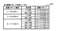
図12は、ROM54に記憶されている当り変動パターン判定テーブル137Aを示す説明図である。当り変動パターン判定テーブル137Aは、可変表示結果を「大当り」にする旨の判定がなされたときに、大当り種別や変動パターン種別の決定結果などに応じて、変動パターン判定用の乱数(ランダム3)にもとづいて、変動パターンを複数種類のうちのいずれかに決定するために参照されるテーブルである。
FIG. 12 is an explanatory diagram showing a hit variation pattern determination table 137A stored in the
当り変動パターン判定テーブル137Aには、変動パターン種別に応じて、変動パターン判定用の乱数(ランダム3)の値と比較される数値(判定値)であって、飾り図柄の可変表示結果が「大当り」である場合に対応した複数種類の変動パターンのいずれかに対応するデータ(判定値)が設定されている。 In the winning variation pattern determination table 137A, a numerical value (determination value) to be compared with a random pattern random number (random 3) value according to the variation pattern type, and the decorative symbol variable display result is “big hit” The data (determination value) corresponding to any of a plurality of types of variation patterns corresponding to the case of “
図13は、ROM54に記憶されているはずれ変動パターン判定テーブル138Aを示す説明図である。はずれ変動パターン判定テーブル138Aは、可変表示結果を「はずれ」にする旨の判定がなされたときに、変動パターン種別の決定結果に応じて、変動パターン判定用の乱数(ランダム3)にもとづいて、変動パターンを複数種類のうちのいずれかに決定するために参照されるテーブルである。はずれ変動パターン判定テーブル138Aは、変動パターン種別の決定結果に応じて、使用テーブルとして選択される。
FIG. 13 is an explanatory diagram showing the deviation variation pattern determination table 138A stored in the
図14は、遊技制御用マイクロコンピュータ560が送信する演出制御コマンドの内容の一例を示す説明図である。図14に示す例において、コマンド80XX(H)は、特別図柄の可変表示に対応して演出表示装置9において可変表示される飾り図柄の変動パターンを指定する演出制御コマンド(変動パターンコマンド)である(それぞれ変動パターンXXに対応)。つまり、図6に示された使用されうる変動パターンのそれぞれに対して一意な番号を付した場合に、その番号で特定される変動パターンのそれぞれに対応する変動パターンコマンドがある。なお、「(H)」は16進数であることを示す。また、変動パターンを指定する演出制御コマンドは、変動開始を指定するためのコマンドでもある。従って、演出制御用マイクロコンピュータ100は、コマンド80XX(H)を受信すると、演出表示装置9において飾り図柄の可変表示を開始するように制御する。
FIG. 14 is an explanatory diagram showing an example of the contents of the effect control command transmitted by the
コマンド8C01(H)〜8C03(H)は、大当りとするか否か、および大当り種別を示す演出制御コマンドである。演出制御用マイクロコンピュータ100は、コマンド8C01(H)〜8C03(H)の受信に応じて飾り図柄の表示結果を決定するので、コマンド8C01(H)〜8C03(H)を表示結果指定コマンドという。
Commands 8C01 (H) to 8C03 (H) are effect control commands indicating whether or not to make a big hit and the type of big hit. The
コマンド8D01(H)は、第1特別図柄の可変表示(変動)を開始することを示す演出制御コマンド(第1図柄変動指定コマンド)である。コマンド8D02(H)は、第2特別図柄の可変表示(変動)を開始することを示す演出制御コマンド(第2図柄変動指定コマンド)である。第1図柄変動指定コマンドと第2図柄変動指定コマンドとを特別図柄特定コマンド(または図柄変動指定コマンド)と総称することがある。なお、第1特別図柄の可変表示を開始するのか第2特別図柄の可変表示を開始するのかを示す情報を、変動パターンコマンドに含めるようにしてもよい。 Command 8D01 (H) is an effect control command (first symbol variation designation command) indicating that variable display (variation) of the first special symbol is started. Command 8D02 (H) is an effect control command (second symbol variation designation command) indicating that variable display (variation) of the second special symbol is started. The first symbol variation designation command and the second symbol variation designation command may be collectively referred to as a special symbol specifying command (or symbol variation designation command). Note that information indicating whether to start variable display of the first special symbol or variable display of the second special symbol may be included in the variation pattern command.
コマンド8F00(H)は、飾り図柄の可変表示(変動)を終了して表示結果(停止図柄)を導出表示することを示す演出制御コマンド(図柄確定指定コマンド)である。演出制御用マイクロコンピュータ100は、図柄確定指定コマンドを受信すると、飾り図柄の可変表示(変動)を終了して表示結果を導出表示する。
Command 8F00 (H) is an effect control command (symbol confirmation designation command) indicating that the variable display (fluctuation) of the decorative symbols is terminated and the display result (stop symbol) is derived and displayed. When receiving the symbol confirmation designation command, the
コマンド9000(H)は、遊技機に対する電力供給が開始されたときに送信される演出制御コマンド(初期化指定コマンド:電源投入指定コマンド)である。コマンド9200(H)は、遊技機に対する電力供給が再開されたときに送信される演出制御コマンド(停電復旧指定コマンド)である。遊技制御用マイクロコンピュータ560は、遊技機に対する電力供給が開始されたときに、バックアップRAMにデータが保存されている場合には、停電復旧指定コマンドを送信し、そうでない場合には、初期化指定コマンドを送信する。
Command 9000 (H) is an effect control command (initialization designation command: power-on designation command) transmitted when power supply to the gaming machine is started. Command 9200 (H) is an effect control command (power failure recovery designation command) transmitted when power supply to the gaming machine is resumed. When the power supply to the gaming machine is started, the
コマンド95XX(H)は、入賞時判定結果の内容を示す演出制御コマンド(入賞時判定結果指定コマンド)である。この実施の形態では、後述する入賞時判定処理(図22参照)において、遊技制御用マイクロコンピュータ560は、始動入賞時に変動パターン種別判定用乱数の値がいずれの判定値の範囲になるかを判定する。そして、入賞時判定結果指定コマンドのEXTデータに判定結果としての判定値の範囲を指定する値を設定し、演出制御用マイクロコンピュータ100に対して送信する制御を行う。なお、この実施の形態では、演出制御用マイクロコンピュータ100は、入賞時判定結果指定コマンドにもとづいて、変動パターン種別判定用乱数の値が所定の判定値と一致する場合には変動パターン種別を認識できるとともに、表示結果が大当りになるか否かも認識できる。
Command 95XX (H) is an effect control command (winning time determination result designation command) indicating the contents of the winning time determination result. In this embodiment, in the winning determination process described later (see FIG. 22), the
なお、この実施の形態では、入賞時判定結果指定コマンドは、第1保留記憶数または第2保留記憶数が1増加したことも示す。すなわち、入賞時判定結果指定コマンドは、保留数増加指定コマンドと兼用されている。ただし、保留数増加指定コマンドを、入賞時判定結果指定コマンドと別個に送信するようにしてもよい。その場合には、入賞時判定結果指定コマンドは、第1保留記憶数または第2保留記憶数が増加したことを意味しない。 In this embodiment, the winning determination result designation command also indicates that the first reserved memory number or the second reserved memory number has increased by one. That is, the winning determination result designation command is also used as the hold increase increase designation command. However, the hold number increase designation command may be transmitted separately from the winning determination result designation command. In this case, the winning determination result designation command does not mean that the first reserved memory number or the second reserved memory number has increased.
コマンド9F00(H)は、客待ちデモンストレーションを指定する演出制御コマンド(客待ちデモ指定コマンド)である。 Command 9F00 (H) is an effect control command (customer waiting demonstration designation command) for designating a customer waiting demonstration.
コマンドA001〜A002(H)は、ファンファーレ画面を表示すること、すなわち大当り遊技の開始を指定する演出制御コマンド(大当り開始指定コマンド:ファンファーレ指定コマンド)である。大当り開始指定コマンドには、大当りの種類に応じた大当り開始1指定コマンドおよび大当り開始指定2指定コマンドがある。
Commands A001 to A002 (H) are effect control commands for displaying a fanfare screen, that is, designating the start of a big hit game (big hit start designation command: fanfare designation command). The jackpot start designation command includes a
コマンドA1XX(H)は、XXで示す回数目(ラウンド)の大入賞口開放中の表示を示す演出制御コマンド(大入賞口開放中指定コマンド)である。A2XX(H)は、XXで示す回数目(ラウンド)の大入賞口閉鎖を示す演出制御コマンド(大入賞口開放後指定コマンド)である。 The command A1XX (H) is an effect control command (special command during opening of a big winning opening) indicating a display during the opening of the big winning opening for the number of times (round) indicated by XX. A2XX (H) is an effect control command (designation command after opening the big winning opening) indicating the closing of the big winning opening for the number of times (round) indicated by XX.
コマンドA301(H)は、大当り終了画面を表示すること、すなわち大当り遊技の終了を指定するとともに、通常大当りであったことを指定する演出制御コマンド(大当り終了1指定コマンド:エンディング1指定コマンド)である。コマンドA302(H)は、大当り終了画面を表示すること、すなわち大当り遊技の終了を指定するとともに、確変大当りであったことを指定する演出制御コマンド(大当り終了2指定コマンド:エンディング2指定コマンド)である。
The command A301 (H) is an effect control command for displaying the jackpot end screen, that is, the end of the jackpot game and specifying that the jackpot game is normally a big jackpot (a
コマンドC200(H)は、第1保留記憶数が1減少したことを指定する演出制御コマンド(第1保留記憶数減算指定コマンド)である。コマンドC300(H)は、第2保留記憶数が1減少したことを指定する演出制御コマンド(第2保留記憶数減算指定コマンド)である。 Command C200 (H) is an effect control command (first reserved memory number subtraction designation command) that specifies that the first reserved memory number has decreased by one. Command C300 (H) is an effect control command (second reserved memory number subtraction designation command) that specifies that the second reserved memory number has decreased by one.
図15および図16は、入賞時判定結果指定コマンドの内容の一例を示す説明図である。図15および図16に示すように、この実施の形態では、第1始動入賞口13または第2始動入賞口14のいずれに始動入賞したときに入賞時判定を行ったかと、いずれの遊技状態であるかと、特別図柄や飾り図柄の表示結果がいずれの表示結果になるかと、始動入賞時に変動パターン種別判定用乱数の値がいずれの判定値の範囲になると判定したとかとに応じて、EXTデータに値が設定され、入賞時判定結果指定コマンドが送信される。
FIG. 15 and FIG. 16 are explanatory diagrams showing an example of the contents of the winning determination result designation command. As shown in FIG. 15 and FIG. 16, in this embodiment, in which gaming state the winning determination is made at which of the first
入賞時判定処理において、大当りになると判定された場合には、大当りの種類に応じた入賞時判定結果指定コマンド(図15に示す入賞時判定結果1指定コマンド〜入賞時判定結果2指定コマンド、図16に示す入賞時判定結果21指定コマンド〜入賞時判定結果22指定コマンドのいずれか)が送信される。
In the winning determination process, if it is determined that a big win is won, a winning determination result specifying command (a winning
また、第1始動入賞口13への始動入賞時に、遊技状態が通常状態で、はずれになると判定した場合、入賞時判定処理において、CPU56は、まず、変動パターン種別判定用乱数の値が1〜79であるか否かを判定する。変動パターン種別判定用乱数の値が1〜79である場合には、CPU56は、EXTデータに「03(H)」を設定した入賞時判定結果3指定コマンドを送信する。この実施の形態では、遊技状態が通常状態である場合には、合算保留記憶数に関わらず、判定値1〜79の範囲には非リーチCA2−1の変動パターン種別(擬似連演出を伴うことがないはずれ変動パターンの集まり)が共通に割り当てられているのであるから(図11参照)、演出制御用マイクロコンピュータ100は、入賞時判定結果8指定コマンドを受信したことにもとづいて、少なくとも変動パターン種別が非リーチCA2−1になることを認識することができる。
In addition, when it is determined that the gaming state is in the normal state and the game state is disengaged when the first winning prize opening 13 is won, in the winning determination process, the
また、CPU56は、変動パターン種別判定用乱数の値が80〜89である場合には、EXTデータに「04(H)」を設定した入賞時判定結果4指定コマンドを送信する。変動パターン種別判定用乱数の値が90〜99である場合には、EXTデータに「05(H)」を設定した入賞時判定結果5指定コマンドを送信する。変動パターン種別判定用乱数の値が100〜169である場合には、EXTデータに「06(H)」を設定した入賞時判定結果6指定コマンドを送信する。変動パターン種別判定用乱数の値が170〜199である場合には、EXTデータに「07(H)」を設定した入賞時判定結果7指定コマンドを送信する。変動パターン種別判定用乱数の値が200〜214である場合には、EXTデータに「08(H)」を設定した入賞時判定結果8指定コマンドを送信する。変動パターン種別判定用乱数の値が215〜229である場合には、EXTデータに「09(H)」を設定した入賞時判定結果9指定コマンドを送信する。変動パターン種別判定用乱数の値が230〜251である場合には、EXTデータに「0A(H)」を設定した入賞時判定結果10指定コマンドを送信する。なお、この実施の形態では、遊技状態が通常状態である場合には、合算保留記憶数にかかわらず、判定値230〜251の範囲にはスーパーCA2−7の変動パターン種別が共通に割り当てられているのであるから、演出制御用マイクロコンピュータ100は、入賞時判定結果15指定コマンドを受信したことにもとづいて、少なくとも変動パターン種別がスーパーCA2−7となることを認識することができる。
When the random number for determining the variation pattern type is 80 to 89, the
また、第1始動入賞口13への始動入賞時に、遊技状態が確変状態または時短状態(確変状態/時短状態)で、はずれになると判定した場合には、CPU56は、変動パターン種別判定用乱数の値が1〜219となるか否かを判定する。変動パターン種別判定用乱数の値が1〜219である場合(すなわち、非リーチCA2−3の変動パターン種別となる場合)には、CPU56は、EXTデータに「0B(H)」を設定した入賞時判定結果11指定コマンドを送信する。変動パターン種別判定用乱数の値が220〜251である場合(すなわち、スーパーCA2−7の変動パターン種別となる場合)には、EXTデータに「0C(H)」を設定した入賞時判定結果12指定コマンドを送信する。
Further, when it is determined that the gaming state is in the probability changing state or the short time state (probability changing state / short time state) at the time of starting winning to the first
なお、遊技状態が確変状態や時短状態である場合にも、判定値230〜251の範囲にスーパーCA2−7の変動パターン種別を割り当てるようにしてもよい。そのようにすれば、遊技状態に関わらず、スーパーCA2−7の変動パターン種別に対して共通の判定値が割り当てられるようにすることができる。 Note that the variation pattern type of the super CA 2-7 may be assigned to the range of the determination values 230 to 251 even when the gaming state is the probability variation state or the short time state. By doing so, it is possible to assign a common determination value to the variation pattern type of the super CA 2-7 regardless of the gaming state.
例えば、第2始動入賞口14への始動入賞時には、CPU56は、第1始動入賞口13への始動入賞時の場合と同様の判定処理によって、入賞時判定結果21指定コマンド〜入賞時判定結果32指定コマンドのいずれかのコマンドを送信する。
For example, at the time of start winning at the second start winning opening 14, the
以下、入賞時判定結果1指定コマンド〜入賞時判定結果12指定コマンドを第1入賞時判定結果指定コマンドといい、入賞時判定結果21指定コマンド〜入賞時判定結果32指定コマンドを第2入賞時判定結果指定コマンドということがある。
Hereinafter, the winning
なお、始動入賞時に入賞時判定を行ったときと実際に変動表示を開始するときとでは必ずしも合算保留記憶数が同じであるとは限らないのであるから、入賞時判定結果指定コマンドで示される変動パターン種別が実際に変動表示で用いられる変動パターン種別と一致しない場合も生じうる。しかし、この実施の形態では、少なくとも非リーチCA2−1およびスーパーCA2−7の変動パターン種別については、合算保留記憶数に関わらず共通の判定値が割り当てられているのであるから(図11参照)、入賞時判定結果と実際に実行される変動表示の変動パターン種別とで不整合が生じない。この実施の形態では、少なくとも非リーチCA2−1およびスーパーCA2−7の変動パターン種別(非リーチCA2−2および非リーチCA2−3の変動パターン種別を含めてもよい。)になると入賞時判定された変動表示に対して予告演出が実行される。また、この実施の形態では、変動パターン種別を特定不能であることに相当する入賞時判定結果指定コマンド(具体的には、保留数が変わると変動パターン種別が変わってしまうことになる判定値範囲に対応する入賞時判定結果指定コマンド:入賞時判定結果4指定コマンド〜入賞時判定結果9指定コマンド、および入賞時判定結果24指定コマンド〜入賞時判定結果29指定コマンド)が送信されるが、変動パターン種別を特定不能であることを示す入賞時判定結果指定コマンドを送信しないようにしてもよい。その場合には、CPU56は、入賞時判定処理において、合算保留記憶数に応じて、変動パターン種別が非リーチになるのか、ノーマルリーチになるのかを判定する。また、CPU56は、予告演出の対象になる変動パターン種別になると判定したときにのみ入賞時判定結果指定コマンドを送信するようにしてもよい。
Note that the total number of pending storage is not always the same when the winning determination is made at the time of starting winning and when the variable display is actually started, so the fluctuation indicated by the winning determination result designation command There may be a case where the pattern type does not coincide with the variation pattern type actually used in the variation display. However, in this embodiment, since at least the non-reach CA 2-1 and the super CA 2-7 variation pattern types are assigned a common determination value regardless of the total number of pending storage (see FIG. 11). Inconsistency does not occur between the winning determination result and the variation pattern type of the variation display actually executed. In this embodiment, when at least the variation pattern types of non-reach CA2-1 and super CA2-7 (the variation pattern types of non-reach CA2-2 and non-reach CA2-3 may be included) are determined at the time of winning. The notice effect is executed for the changed display. Also, in this embodiment, a winning determination result designation command corresponding to the fact that the variation pattern type cannot be specified (specifically, a determination value range in which the variation pattern type will change if the number of holds changes) Winning determination result designation command corresponding to: winning
また、この実施の形態では、第1始動入賞口13への始動入賞時と第2始動入賞口14への始動入賞時とで共通のMODEデータが「95(H)」である入賞時判定結果指定コマンドを送信するが、第1始動入賞口13への始動入賞時と第2始動入賞口14への始動入賞時とで入賞時判定結果指定コマンドのMODEデータを異ならせてもよい。例えば、第1始動入賞口13への始動入賞時には、MODEデータが「95(H)」である入賞時結果指定コマンドを送信し、第2始動入賞口14への始動入賞時には、MODEデータが「96(H)」である入賞時結果指定コマンドを送信する。その場合に、第1始動入賞口13への始動入賞時であるか第2始動入賞口14への始動入賞時であるかに関わらず、いずれの遊技状態であるかと、特別図柄や飾り図柄の表示結果がいずれの表示結果になるかと、始動入賞時に変動パターン種別判定用乱数の値がいずれの判定値の範囲になると判定したとかとに応じて、共通のEXTデータを含む入賞時判定結果指定コマンドを送信するようにしてもよい。
Further, in this embodiment, the winning determination result in which the MODE data common to the start winning to the first
演出制御基板80に搭載されている演出制御用マイクロコンピュータ100(具体的には、演出制御用CPU101)は、主基板31に搭載されている遊技制御用マイクロコンピュータ560から上述した演出制御コマンドを受信すると、図14〜図16に示された内容に応じて画像表示装置9の表示状態を変更したり、ランプの表示状態を変更したり、音声出力基板70に対して音番号データを出力したりする。
The effect control microcomputer 100 (specifically, the effect control CPU 101) mounted on the
例えば、遊技制御用マイクロコンピュータ560は、始動入賞があり第1特別図柄表示器8aまたは第2特別図柄表示器8bにおいて特別図柄の可変表示が開始される度に、飾り図柄の変動パターンを指定する変動パターンコマンドおよび表示結果指定コマンドを演出制御用マイクロコンピュータ100に送信する。
For example, the
この実施の形態では、演出制御コマンドは2バイト構成であり、1バイト目はMODE(コマンドの分類)を表し、2バイト目はEXT(コマンドの種類)を表す。MODEデータの先頭ビット(ビット7)は必ず「1」に設定され、EXTデータの先頭ビット(ビット7)は必ず「0」に設定される。なお、そのようなコマンド形態は一例であって他のコマンド形態を用いてもよい。例えば、1バイトや3バイト以上で構成される制御コマンドを用いてもよい In this embodiment, the presentation control command has a 2-byte structure, the first byte represents MODE (command classification), and the second byte represents EXT (command type). The first bit (bit 7) of the MODE data is always set to “1”, and the first bit (bit 7) of the EXT data is always set to “0”. Note that such a command form is an example, and other command forms may be used. For example, a control command composed of 1 byte or 3 bytes or more may be used.
なお、演出制御コマンドの送出方式として、演出制御信号CD0〜CD7の8本のパラレル信号線で1バイトずつ主基板31から中継基板77を介して演出制御基板80に演出制御コマンドデータを出力し、演出制御コマンドデータの他に、演出制御コマンドデータの取込を指示するパルス状(矩形波状)の取込信号(演出制御INT信号)を出力する方式を用いる。演出制御コマンドの8ビットの演出制御コマンドデータは、演出制御INT信号に同期して出力される。演出制御基板80に搭載されている演出制御用マイクロコンピュータ100は、演出制御INT信号が立ち上がったことを検知して、割込処理によって1バイトのデータの取り込み処理を開始する。
In addition, as the transmission method of the effect control command, the effect control command data is output from the
図17および図18は、主基板31に搭載される遊技制御用マイクロコンピュータ560(具体的には、CPU56)が実行する特別図柄プロセス処理(ステップS26)のプログラムの一例を示すフローチャートである。上述したように、特別図柄プロセス処理では第1特別図柄表示器8aまたは第2特別図柄表示器8bおよび大入賞口を制御するための処理が実行される。特別図柄プロセス処理において、CPU56は、第1始動入賞口13に遊技球が入賞したことを検出するための第1始動口スイッチ13aがオンしていたら、すなわち、第1始動入賞口13への始動入賞が発生していたら、第1始動口スイッチ通過処理を実行する(ステップS311,S312)。また、CPU56は、第2始動入賞口14に遊技球が入賞したことを検出するための第2始動口スイッチ14aがオンしていたら、すなわち第2始動入賞口14への始動入賞が発生していたら、第2始動口スイッチ通過処理を実行する(ステップS313,S314)。そして、ステップS300〜S307のうちのいずれかの処理を行う。第1始動入賞口スイッチ13aまたは第2始動口スイッチ14aがオンしていない場合には、内部状態に応じて、ステップS300〜S307のうちのいずれかの処理を行う。
FIGS. 17 and 18 are flowcharts showing an example of a special symbol process (step S26) program executed by the game control microcomputer 560 (specifically, the CPU 56) mounted on the
ステップS300〜S307の処理は、以下のような処理である。 The processes in steps S300 to S307 are as follows.
特別図柄通常処理(ステップS300):特別図柄プロセスフラグの値が0であるときに実行される。遊技制御用マイクロコンピュータ560は、特別図柄の可変表示が開始できる状態になると、保留記憶数バッファに記憶される数値データの記憶数(合算保留記憶数)を確認する。保留記憶数バッファに記憶される数値データの記憶数は合算保留記憶数カウンタのカウント値により確認できる。また、合算保留記憶数カウンタのカウント値が0でなければ、第1特別図柄または第2特別図柄の可変表示の表示結果を大当りとするか否かを決定する。大当りとする場合には大当りフラグをセットする。そして、内部状態(特別図柄プロセスフラグ)をステップS301に応じた値(この例では1)に更新する。なお、大当りフラグは、大当り遊技が終了するときにリセットされる。
Special symbol normal processing (step S300): Executed when the value of the special symbol process flag is zero. When the
変動パターン設定処理(ステップS301):特別図柄プロセスフラグの値が1であるときに実行される。また、変動パターンを決定し、その変動パターンにおける変動時間(可変表示時間:可変表示を開始してから表示結果を導出表示(停止表示)するまでの時間)を特別図柄の可変表示の変動時間とすることに決定する。また、特別図柄の変動時間を計測する変動時間タイマをスタートさせる。そして、内部状態(特別図柄プロセスフラグ)をステップS302に対応した値(この例では2)に更新する。 Fluctuation pattern setting process (step S301): This process is executed when the value of the special symbol process flag is 1. Also, the variation pattern is determined, and the variation time in the variation pattern (variable display time: the time from the start of variable display until the display result is derived and displayed (stop display)) is defined as the variation display variation time of the special symbol. Decide to do. Also, a variable time timer for measuring the special symbol variable time is started. Then, the internal state (special symbol process flag) is updated to a value (2 in this example) corresponding to step S302.
表示結果指定コマンド送信処理(ステップS302):特別図柄プロセスフラグの値が2であるときに実行される。演出制御用マイクロコンピュータ100に、表示結果指定コマンドを送信する制御を行う。そして、内部状態(特別図柄プロセスフラグ)をステップS303に対応した値(この例では3)に更新する。
Display result designation command transmission process (step S302): This process is executed when the value of the special symbol process flag is 2. Control for transmitting a display result designation command to the
特別図柄変動中処理(ステップS303):特別図柄プロセスフラグの値が3であるときに実行される。変動パターン設定処理で選択された変動パターンの変動時間が経過(ステップS301でセットされる変動時間タイマがタイムアウトすなわち変動時間タイマの値が0になる)すると、演出制御用マイクロコンピュータ100に、図柄確定指定コマンドを送信する制御を行い、内部状態(特別図柄プロセスフラグ)をステップS304に対応した値(この例では4)に更新する。
Special symbol changing process (step S303): This process is executed when the value of the special symbol process flag is 3. When the variation time of the variation pattern selected in the variation pattern setting process elapses (the variation time timer set in step S301 times out, that is, the variation time timer value becomes 0), the
特別図柄停止処理(ステップS304):特別図柄プロセスフラグの値が4であるときに実行される。大当りフラグがセットされている場合に、内部状態(特別図柄プロセスフラグ)をステップS305に対応した値(この例では5)に更新する。大当りフラグがセットされていない場合には、内部状態(特別図柄プロセスフラグ)をステップS300に対応した値(この例では0)に更新する。なお、この実施の形態では、特別図柄プロセスフラグの値が4となったことにもとづいて、後述するように、特別図柄表示制御処理において特別図柄の停止図柄を停止表示するための特別図柄表示制御データが特別図柄表示制御データ設定用の出力バッファに設定され、ステップS22の表示制御処理において出力バッファの設定内容に応じて実際に特別図柄の停止図柄が停止表示される。 Special symbol stop process (step S304): executed when the value of the special symbol process flag is 4. When the big hit flag is set, the internal state (special symbol process flag) is updated to a value (5 in this example) corresponding to step S305. If the big hit flag is not set, the internal state (special symbol process flag) is updated to a value corresponding to step S300 (0 in this example). In this embodiment, as will be described later, a special symbol display control for stopping and displaying a special symbol stop symbol in the special symbol display control process based on the fact that the value of the special symbol process flag is 4. The data is set in the output buffer for setting the special symbol display control data, and the special symbol stop symbol is actually stopped and displayed according to the setting contents of the output buffer in the display control processing in step S22.
大入賞口開放前処理(ステップS305):特別図柄プロセスフラグの値が5であるときに実行される。大入賞口開放前処理では、大入賞口を開放する制御を行う。具体的には、カウンタ(例えば、大入賞口に入った遊技球数をカウントするカウンタ)などを初期化するとともに、ソレノイド21を駆動して大入賞口を開放状態にする。また、タイマによって大入賞口開放中処理の実行時間を設定し、内部状態(特別図柄プロセスフラグ)をステップS306に対応した値(この例では6)に更新する。なお、大入賞口開放前処理は各ラウンド毎に実行されるが、第1ラウンドを開始する場合には、大入賞口開放前処理は大当り遊技を開始する処理でもある。
Preliminary winning opening opening process (step S305): This is executed when the value of the special symbol process flag is 5. In the pre-opening process for the big prize opening, control for opening the big prize opening is performed. Specifically, a counter (for example, a counter that counts the number of game balls that have entered the big prize opening) is initialized and the
大入賞口開放中処理(ステップS306):特別図柄プロセスフラグの値が6であるときに実行される。大当り遊技状態中のラウンド表示の演出制御コマンドを演出制御用マイクロコンピュータ100に送信する制御や大入賞口の閉成条件の成立を確認する処理等を行う。大入賞口の閉成条件が成立し、かつ、まだ残りラウンドがある場合には、内部状態(特別図柄プロセスフラグ)をステップS305に対応した値(この例では5)に更新する。また、全てのラウンドを終えた場合には、内部状態(特別図柄プロセスフラグ)をステップS307に対応した値(この例では7)に更新する。
Large winning opening opening process (step S306): This process is executed when the value of the special symbol process flag is 6. A control for transmitting an effect control command for round display during the big hit gaming state to the
大当り終了処理(ステップS307):特別図柄プロセスフラグの値が7であるときに実行される。大当り遊技状態が終了したことを遊技者に報知する表示制御を演出制御用マイクロコンピュータ100に行わせるための制御を行う。また、遊技状態を示すフラグ(例えば、確変フラグや時短フラグ)をセットする処理を行う。そして、内部状態(特別図柄プロセスフラグ)をステップS300に対応した値(この例では0)に更新する。
Big hit end process (step S307): executed when the value of the special symbol process flag is 7. Control is performed to cause the
図19は、ステップS312の第1始動口スイッチ通過処理を示すフローチャートである。図20は、ステップS314の第2始動口スイッチ通過処理を示すフローチャートである。 FIG. 19 is a flowchart showing the first start port switch passing process in step S312. FIG. 20 is a flowchart showing the second start port switch passing process in step S314.
図19を参照して第1始動口スイッチ通過処理について説明する。第1始動口スイッチ13aがオン状態の場合に実行される第1始動口スイッチ通過処理において、CPU56は、第1保留記憶数が上限値に達しているか否か(具体的には、第1保留記憶数をカウントするための第1保留記憶数カウンタの値が4でるか否か)を確認する(ステップS211A)。第1保留記憶数が上限値に達している場合には、処理を終了する。
The first start port switch passing process will be described with reference to FIG. In the first start port switch passing process executed when the first
第1保留記憶数が上限値に達していない場合には、CPU56は、第1保留記憶数カウンタの値を1増やす(ステップS212A)とともに、合算保留記憶数をカウントするための合算保留記憶数カウンタの値を1増やす(ステップS213A)。次いで、CPU56は、乱数回路503やソフトウェア乱数を生成するためのカウンタから値を抽出し、それらを、第1保留記憶バッファ(図21参照)における保存領域に格納する処理を実行する(ステップS214A)。なお、ステップS214Aの処理では、ハードウェア乱数であるランダムR(大当り判定用乱数)や、ソフトウェア乱数である大当り種別判定用乱数(ランダム1)、変動パターン種別判定用乱数(ランダム2)および変動パターン判定用乱数(ランダム3)が抽出され、保存領域に格納される。なお、変動パターン判定用乱数(ランダム3)を第1始動口スイッチ通過処理(始動入賞時)において抽出して保存領域にあらかじめ格納しておくのではなく、第1特別図柄の変動開始時に抽出するようにしてもよい。例えば、遊技制御用マイクロコンピュータ560は、変動パターン設定処理において、変動パターン判定用乱数(ランダム3)を生成するための変動パターン判定用乱数カウンタから値を直接抽出するようにしてもよい。
If the first reserved memory number has not reached the upper limit value, the
図21は、保留記憶に対応する乱数等を保存する領域(保留バッファ)の構成例を示す説明図である。図21に示すように、第1保留記憶バッファには、第1保留記憶数の上限値(この例では4)に対応した保存領域が確保されている。また、第2保留記憶バッファには、第2保留記憶数の上限値(この例では4)に対応した保存領域が確保されている。この実施の形態では、第1保留記憶バッファおよび第2保留記憶バッファには、ハードウェア乱数であるランダムR(大当り判定用乱数)や、ソフトウェア乱数である大当り種別判定用乱数(ランダム1)、変動パターン種別判定用乱数(ランダム2)および変動パターン判定用乱数(ランダム3)が記憶される。なお、第1保留記憶バッファおよび第2保留記憶バッファは、RAM55に形成されている。
FIG. 21 is an explanatory diagram showing a configuration example of an area (hold buffer) for storing random numbers and the like corresponding to the hold memory. As shown in FIG. 21, a storage area corresponding to the upper limit value (4 in this example) of the first reserved storage number is secured in the first reserved storage buffer. In addition, a storage area corresponding to the upper limit value of the second reserved storage number (4 in this example) is secured in the second reserved storage buffer. In this embodiment, the first reserved storage buffer and the second reserved storage buffer include a random R (big hit determination random number) that is a hardware random number, a big hit type determination random number (random 1) that is a software random number, a variation A random number for pattern type determination (random 2) and a random number for variation pattern determination (random 3) are stored. The first reserved storage buffer and the second reserved storage buffer are formed in the
次いで、CPU56は、検出した始動入賞にもとづく変動がその後実行されたときの変動表示結果を始動入賞時にあらかじめ判定する入賞時判定処理を実行する(ステップS217A)。そして、入賞時判定処理の判定結果にもとづいて入賞時判定結果指定コマンドを演出制御用マイクロコンピュータ100に送信する制御を行う(ステップS218A)。
Next, the
なお、具体的には、CPU56は、演出制御用マイクロコンピュータ100に演出制御コマンドを送信する際に、演出制御コマンドに応じたコマンド送信テーブル(あらかじめROMにコマンド毎に設定されている)のアドレスをポインタにセットする。そして、演出制御コマンドに応じたコマンド送信テーブルのアドレスをポインタにセットして、演出制御コマンド制御処理(ステップS28)において演出制御コマンドを送信する。
Specifically, when the
なお、この実施の形態において、大当り遊技状態(特定遊技状態)とは、大当りを開始することが報知されてから、所定数のラウンド(15ラウンド)にわたって大入賞口が開放する制御が行われ、最終ラウンドの大入賞口の開放を終了して大当りを終了することが報知されるまでの状態である。具体的には、特別図柄プロセス処理における大入賞口開放前処理(ステップS305)から大当り終了処理(ステップS307)までの処理が実行されている状態である。 In this embodiment, the jackpot gaming state (specific gaming state) is controlled to open the jackpot over a predetermined number of rounds (15 rounds) after being notified that the jackpot will start. This is the state until the end of the big round winning opening in the final round and the notification of the end of the big hit. Specifically, it is a state in which the processing from the big winning opening opening pre-processing (step S305) to the big hit end processing (step S307) in the special symbol process is being executed.
次に、図20を参照して第2始動口スイッチ通過処理について説明する。第2始動口スイッチ14aがオン状態の場合に実行される第2始動口スイッチ通過処理において、CPU56は、第2保留記憶数が上限値に達しているか否か(具体的には、第2保留記憶数をカウントするための第2保留記憶数カウンタの値が4でるか否か)を確認する(ステップS211B)。第2保留記憶数が上限値に達している場合には、処理を終了する。
Next, the second start port switch passage process will be described with reference to FIG. In the second start port switch passing process that is executed when the second
第2保留記憶数が上限値に達していない場合には、CPU56は、第2保留記憶数カウンタの値を1増やす(ステップS212B)とともに、合算保留記憶数をカウントするための合算保留記憶数カウンタの値を1増やす(ステップS213B)。次いで、CPU56は、乱数回路503やソフトウェア乱数を生成するためのカウンタから値を抽出し、それらを、第2保留記憶バッファ(図21参照)における保存領域に格納する処理を実行する(ステップS214B)。なお、ステップS214Bの処理では、ハードウェア乱数であるランダムR(大当り判定用乱数)や、ソフトウェア乱数である大当り種別判定用乱数(ランダム1)、変動パターン種別判定用乱数(ランダム2)および変動パターン判定用乱数(ランダム3)が抽出され、保存領域に格納される。また、変動パターン判定用乱数(ランダム3)を第2始動口スイッチ通過処理(始動入賞時)において抽出して保存領域にあらかじめ格納しておくのではなく、第2特別図柄の変動開始時に抽出するようにしてもよい。例えば、遊技制御用マイクロコンピュータ560は、後述する変動パターン設定処理において、変動パターン判定用乱数(ランダム3)を生成するための変動パターン判定用乱数カウンタから値を直接抽出するようにしてもよい。また、大当り判定用乱数および大当り種別判定用乱数以外の乱数について、第2保留記憶バッファにおける保存領域に格納される乱数の種類を、第1保留記憶バッファにおける保存領域に格納される乱数の種類と異ならせてもよい。例えば、第2始動口スイッチ14aがオン状態になったときには、変動パターン種別判定用乱数(ランダム2)および変動パターン判定用乱数(ランダム3)を第2保留記憶バッファにおける保存領域に格納しない。そのように制御する場合には、第2保留記憶バッファとして要求されるメモリ領域が削減される。
When the second reserved memory number has not reached the upper limit value, the
次いで、CPU56は、入賞時判定処理を実行する(ステップS217B)。そして、入賞時判定処理の判定結果にもとづいて入賞時判定結果指定コマンドを演出制御用マイクロコンピュータ100に送信する制御を行う(ステップS218B)。
Next, the
図22は、ステップS217A,S217Bの入賞時判定処理を示すフローチャートである。 FIG. 22 is a flowchart showing the winning determination process in steps S217A and S217B.
この実施の形態では、特別図柄および飾り図柄の変動を開始するタイミングで、特別図柄通常処理において大当りとするか否かを決定したり、大当り種別を決定したり、変動パターン設定処理において変動パターンを決定したりするのであるが、遊技球が第1始動入賞口13や第2始動入賞口14に始動入賞したタイミングでも、その始動入賞にもとづく変動表示が開始される前に、図22に示す入賞時判定処理を実行することによって、あらかじめ変動パターン種別判定用乱数の値がいずれの判定値の範囲になるかを確認する。すなわち、飾り図柄の変動表示が実行されるより前にあらかじめ変動パターン種別を判定し、入賞時の判定結果にもとづいて、演出制御用マイクロコンピュータ100によって大当りやスーパーリーチになることを予告する予告演出を実行する。
In this embodiment, at the timing of starting the variation of the special symbol and the decorative symbol, it is determined whether or not to make a big hit in the special symbol normal processing, the big hit type is determined, and the variation pattern is set in the variation pattern setting processing. Even if the game ball starts at the first
入賞時判定処理では、CPU56は、まず、ステップS214A,S214Bで抽出した大当り判定用乱数(ランダムR)と図8の左欄に示す通常時の大当り判定値とを比較し、それらが一致するか否かを確認する(ステップS220)。ステップS220で大当り判定用乱数(ランダムR)が通常時の大当り判定値と一致しないことを確認した場合には、CPU56は、遊技状態が確変状態であることを示す確変フラグがセットされているか否かを確認する(ステップS221)。確変フラグがセットされている場合には、ステップS214A,S214Bの処理で抽出した大当り判定用乱数(ランダムR)と図8の右欄に示す確変時の大当り判定値とを比較し、それらが一致するか否かを確認する(ステップS222)。なお、始動入賞時にステップS221で確変状態であるか否かを確認してから、実際にその始動入賞にもとづく変動表示が開始されるまでの間には、複数の変動表示が実行される可能性がある。そのため、始動入賞時にステップS221で確変状態であるか否かを確認してから、実際にその始動入賞にもとづく変動表示が開始されるまでの間に遊技状態が変化している(例えば、変動開始前に確変大当りが発生した場合には通常状態から確変状態に変化している。)場合がある。そのため、始動入賞時にステップS221で判定する遊技状態と変動開始時に判定する遊技状態(図24におけるステップS61参照)とは、必ずしも一致するとは限らない。
In the winning determination process, the
大当り判定用乱数(ランダムR)がいずれかの大当り判定値と一致する場合には、CPU56は、ステップS214A,S214Bで抽出し保留記憶バッファに保存した大当り種別判定用乱数(ランダム1)にもとづいて大当たりの種別を判定する(ステップS224)。ステップS224では、CPU56は、図9に示す大当り種別判定テーブルを用いて大当り種別が「確変大当り」または「非確変大当り」(通常大当り)になるかを判定する。そして、ステップS230に移行する。
When the big hit determination random number (random R) matches any of the big hit determination values, the
大当り判定用乱数(ランダムR)が確変時の大当り判定値とも一致しない場合には、CPU56は、現在の遊技状態を判定する処理を行う(ステップS226)。この実施の形態では、CPU56は、ステップS226において、遊技状態が確変状態または時短状態であるか否か(具体的には、時短フラグがセットされているか否か)を判定する。なお、始動入賞時にステップS226で確変状態や時短状態であるか否かを確認してから、実際にその始動入賞にもとづく変動表示が開始されるまでの間には、複数の変動表示が実行される可能性がある。そのため、始動入賞時にステップS226で確変状態や時短状態であるか否かを確認してから、実際にその始動入賞にもとづく変動表示が開始されるまでの間に遊技状態が変化している(例えば、変動開始前に確変大当りが発生した場合には通常状態から確変状態に変化している。)場合がある。すなわち、始動入賞時にステップS226の処理で判定する遊技状態と変動開始時に判定する遊技状態(図24におけるステップS61参照)とは、必ずしも一致するとは限らない。
When the jackpot determination random number (random R) does not match the jackpot determination value at the time of probability change, the
そして、CPU56は、ステップS226の判定結果に応じて、はずれ用の各閾値を設定する(ステップS227)。CPU56は、閾値より大きいか否かを判定することによって、変動パターン種別判定用乱数の値がいずれの判定値の範囲にとなるかを判定し、図15〜図16に示す入賞時判定結果指定コマンドに設定するEXTデータの値を決定する。
Then, the
例えば、CPU56は、遊技状態が確変状態または時短状態であると判定した場合には閾値219を設定する。この場合、CPU56は、ステップS228の処理で、変動パターン種別判定用乱数の値が閾値219以下であるか否か判定し、閾値219以下である場合(すなわち、1〜219である場合)には第1始動入賞口13に始動入賞した場合であれば入賞時判定結果指定コマンドのEXTデータとして「0B(H)」を設定すると判定し、第2始動入賞口14に始動入賞した場合であれば入賞時判定結果指定コマンドのEXTデータとして「2B(H)」を設定すると判定する(図15,図16参照)。また、閾値219以下でない場合(すなわち、220〜251である場合)には第1始動入賞口13に始動入賞した場合であれば入賞時判定結果指定コマンドのEXTデータとして「0C(H)」を設定すると判定し、第2始動入賞口14に始動入賞した場合であれば入賞時判定結果指定コマンドのEXTデータとして「2C(H)」を設定すると判定する(図15,図16参照)。
For example, the
また、例えば、CPU56は、遊技状態が通常状態であると判定した場合には、合算保留記憶数にかかわらず、閾値79、89、99、169、199、214および229を設定する。この場合、CPU56は、ステップS228の処理で、変動パターン種別判定用乱数の値が閾値79以下であるか否かを判定し、閾値79以下である場合(すなわち、1〜79である場合)には第1始動入賞口13に始動入賞した場合であれば入賞時判定結果指定コマンドのEXTデータとして「03(H)」を設定すると判定し、第2始動入賞口14に始動入賞した場合であれば入賞時判定結果指定コマンドのEXTデータとして「23(H)」を設定すると判定する(図15,図16参照)。また、閾値89以下である場合(すなわち、80〜89である場合)には第1始動入賞口13に始動入賞した場合であれば入賞時判定結果指定コマンドのEXTデータとして「04(H)」を設定すると判定し、第2始動入賞口14に始動入賞した場合であれば入賞時判定結果指定コマンドのEXTデータとして「24(H)」を設定すると判定する(図15,図16参照)。また、閾値99以下である場合(すなわち、90〜99である場合)には第1始動入賞口13に始動入賞した場合であれば入賞時判定結果指定コマンドのEXTデータとして「05(H)」を設定すると判定し、第2始動入賞口14に始動入賞した場合であれば入賞時判定結果指定コマンドのEXTデータとして「25(H)」を設定すると判定する(図15,図16参照)。また、閾値169以下である場合(すなわち、100〜169である場合)には第1始動入賞口13に始動入賞した場合であれば入賞時判定結果指定コマンドのEXTデータとして「06(H)」を設定すると判定し、第2始動入賞口14に始動入賞した場合であれば入賞時判定結果指定コマンドのEXTデータとして「26(H)」を設定すると判定する(図15,図16参照)。また、閾値199以下である場合(すなわち、170〜199である場合)には第1始動入賞口13に始動入賞した場合であれば入賞時判定結果指定コマンドのEXTデータとして「07(H)」を設定すると判定し、第2始動入賞口14に始動入賞した場合であれば入賞時判定結果指定コマンドのEXTデータとして「27(H)」を設定すると判定する(図15,図16参照)。また、閾値214以下である場合(すなわち、200〜214である場合)には第1始動入賞口13に始動入賞した場合であれば入賞時判定結果指定コマンドのEXTデータとして「08(H)」を設定すると判定し、第2始動入賞口14に始動入賞した場合であれば入賞時判定結果指定コマンドのEXTデータとして「28(H)」を設定すると判定する(図15,図16参照)。また、閾値229以下である場合(すなわち、215〜229である場合)には第1始動入賞口13に始動入賞した場合であれば入賞時判定結果指定コマンドのEXTデータとして「09(H)」を設定すると判定し、第2始動入賞口14に始動入賞した場合であれば入賞時判定結果指定コマンドのEXTデータとして「29(H)」を設定すると判定する(図15,図16参照)。また、閾値229以下でない場合(すなわち、230〜251である場合)には第1始動入賞口13に始動入賞した場合であれば入賞時判定結果指定コマンドのEXTデータとして「0A(H)」を設定すると判定し、第2始動入賞口14に始動入賞した場合であれば入賞時判定結果指定コマンドのEXTデータとして「2A(H)」を設定すると判定する(図15,図16参照)。
For example, if the
なお、始動入賞時にステップS226の処理で確変状態や時短状態であるか否かを確認してから、実際にその始動入賞にもとづく変動表示が開始されるまでの間には、複数の変動表示が実行される可能性がある。従って、始動入賞時にステップS226の処理で確変状態や時短状態であるか否かを確認してから、実際にその始動入賞にもとづく変動表示が開始されるまでの間に遊技状態が変化している(例えば、変動開始前に確変大当りが発生した場合には通常状態から確変状態に変化している。)場合がある。よって、ステップS226の処理で判定される遊技状態と変動開始時に判定する遊技状態(図24におけるステップS61参照)とは、必ずしも一致するとは限らない。 It should be noted that a plurality of variable displays are displayed during the period from the confirmation of whether or not the state of probability change or short time is confirmed in the process of step S226 at the time of starting winning, until the actual starting of changing display based on the starting winning. May be executed. Accordingly, the game state has changed from the time when the winning winning is confirmed in the process of step S226 to the time when the variation display based on the starting winning is actually started after confirming whether or not the state has been changed. (For example, when a probable big hit occurs before the start of fluctuation, the normal state changes to the probable state.). Therefore, the gaming state determined in the process of step S226 and the gaming state determined at the start of variation (see step S61 in FIG. 24) do not necessarily match.
そして、CPU56は、ステップS224,S228の判定結果に応じたEXTデータを入賞時判定結果指定コマンドに設定する処理を行う(ステップS230)。ステップS230では、CPU56は、第1始動入賞口13または第2始動入賞口14のいずれに始動入賞したときに入賞時判定を行ったかと、ステップS224,S228の判定結果とに応じて、図15および図16に示す「01(H)」〜「0C(H)」、「21(H)」〜「2C(H)」のいずれかの値を入賞時判定結果指定コマンドのEXTデータに設定する処理を行う。
Then, the
図23および図24は、特別図柄プロセス処理における特別図柄通常処理(ステップS300)を示すフローチャートである。特別図柄通常処理において、CPU56は、合算保留記憶数の値を確認する(ステップS51)。具体的には、合算保留記憶数カウンタのカウント値を確認する。合算保留記憶数が0であれば、まだ客待ちデモ指定コマンドを送信していない場合には、演出制御用マイクロコンピュータ100に対して客待ちデモ指定コマンドを送信する制御を行い(ステップS51A)、処理を終了する。
23 and 24 are flowcharts showing the special symbol normal process (step S300) in the special symbol process. In the special symbol normal process, the
合算保留記憶数が0でなければ、CPU56は、第2保留記憶数が0であるか否かを確認する(ステップS52)。具体的には、第2保留記憶数カウンタの値が0であるか否かを確認する。第2保留記憶数が0でなければ、CPU56は、特別図柄ポインタ(第1特別図柄について特別図柄プロセス処理を行っているのか第2特別図柄について特別図柄プロセス処理を行っているのかを示すフラグ)に「第2」を示すデータを設定する(ステップS53)。第2保留記憶数が0であれば(すなわち、第1保留記憶数のみが溜まっている場合)には、CPU66は、特別図柄ポインタに「第1」を示すデータを設定する(ステップS54)。
If the total reserved memory number is not 0, the
この実施の形態では、ステップS52〜S54の処理が実行されることによって、第1特別図柄の変動表示に対して、第2特別図柄の変動表示が優先して実行される。言い換えれば、第2特別図柄の変動表示を開始させるための第2の開始条件が第1特別図柄の変動表示を開始させるための第1の開始条件に優先して成立するように制御される。 In this embodiment, by executing the processing of steps S52 to S54, the variation display of the second special symbol is executed with priority over the variation display of the first special symbol. In other words, the second start condition for starting the variable display of the second special symbol is controlled to be satisfied in preference to the first start condition for starting the variable display of the first special symbol.
次いで、CPU56は、RAM55において、特別図柄ポインタが示す方の保留記憶数=1に対応する保存領域に格納されている各乱数値を読み出してRAM55の乱数バッファ領域に格納する(ステップS55)。具体的には、CPU56は、特別図柄ポインタが「第1」を示している場合には、第1保留記憶数バッファにおける第1保留記憶数=1に対応する保存領域に格納されている各乱数値を読み出してRAM55の乱数バッファ領域に格納する。また、CPU56は、特別図柄ポインタが「第2」を示している場合には、第2保留記憶数バッファにおける第2保留記憶数=1に対応する保存領域に格納されている各乱数値を読み出してRAM55の乱数バッファ領域に格納する。
Next, the
そして、CPU56は、特別図柄ポインタが示す方の保留記憶数カウンタのカウント値を1減算し、かつ、各保存領域の内容をシフトする(ステップS56)。具体的には、CPU56は、特別図柄ポインタが「第1」を示している場合には、第1保留記憶数カウンタのカウント値を1減算し、かつ、第1保留記憶数バッファにおける各保存領域の内容をシフトする。また、特別図柄ポインタが「第2」を示している場合に、第2保留記憶数カウンタのカウント値を1減算し、かつ、第2保留記憶数バッファにおける各保存領域の内容をシフトする。
Then, the
すなわち、CPU56は、特別図柄ポインタが「第1」を示している場合に、RAM55の第1保留記憶数バッファにおいて第1保留記憶数=n(n=2,3,4)に対応する保存領域に格納されている各乱数値を、第1保留記憶数=n−1に対応する保存領域に格納する。また、特別図柄ポインタが「第2」を示す場合に、RAM55の第2保留記憶数バッファにおいて第2保留記憶数=n(n=2,3,4)に対応する保存領域に格納されている各乱数値を、第2保留記憶数=n−1に対応する保存領域に格納する。
That is, when the special symbol pointer indicates “first”, the
よって、各第1保留記憶数(または、各第2保留記憶数)に対応するそれぞれの保存領域に格納されている各乱数値が抽出された順番は、常に、第1保留記憶数(または、第2保留記憶数)=1,2,3,4の順番と一致するようになっている。 Therefore, the order in which each random value stored in each storage area corresponding to each first reserved memory number (or each second reserved memory number) is extracted is always the first reserved memory number (or (Second reserved storage number) = 1, 2, 3, 4 in order.
そして、CPU56は、合算保留記憶数の値を1減らす。すなわち、合算保留記憶数カウンタのカウント値を1減算する(ステップS58)。なお、CPU56は、カウント値が1減算される前の合算保留記憶数カウンタの値をRAM55の所定の領域に保存する。
Then, the
特別図柄通常処理では、最初に、第1始動入賞口13を対象として処理を実行することを示す「第1」を示すデータすなわち第1特別図柄を対象として処理を実行することを示す「第1」を示すデータ、または第2始動入賞口14を対象として処理を実行することを示す「第2」を示すデータすなわち第2特別図柄を対象として処理を実行することを示す「第2」を示すデータが、特別図柄ポインタに設定される。そして、特別図柄プロセス処理における以降の処理では、特別図柄ポインタに設定されているデータに応じた処理が実行される。よって、ステップS300〜S307の処理を、第1特別図柄を対象とする場合と第2特別図柄を対象とする場合とで共通化することができる。
In the special symbol normal process, first, data indicating “first” indicating that the process is executed for the first
次いで、CPU56は、乱数バッファ領域からランダムR(大当り判定用乱数)を読み出し、大当り判定モジュールを実行する。なお、この場合、CPU56は、第1始動口スイッチ通過処理のステップS214Aや第2始動口スイッチ通過処理のステップS214Bで抽出し第1保留記憶バッファや第2保留記憶バッファに格納した大当り判定用乱数を読み出し、大当り判定を行う。大当り判定モジュールは、あらかじめ決められている大当り判定値(図8参照)と大当り判定用乱数とを比較し、それらが一致したら大当りとすることに決定する処理を実行するプログラムである。すなわち、大当り判定の処理を実行するプログラムである。
Next, the
大当り判定の処理では、遊技状態が確変状態(高確率状態)の場合は、遊技状態が非確変状態(通常遊技状態および時短状態)の場合よりも、大当りになる確率が高くなるように構成されている。具体的には、あらかじめ大当り判定値の数が多く設定されている確変時大当り判定テーブル(ROM54における図8の右側の数値が設定されているテーブル)と、大当り判定値の数が確変大当り判定テーブルよりも少なく設定されている通常時大当り判定テーブル(ROM54における図8の左側の数値が設定されているテーブル)とが設けられている。そして、CPU56は、遊技状態が確変状態であるか否かを確認し、遊技状態が確変状態であるときは、確変時大当り判定テーブルを使用して大当りの判定の処理を行い、遊技状態が通常遊技状態や時短状態であるときは、通常時大当り判定テーブルを使用して大当りの判定の処理を行う。すなわち、CPU56は、大当り判定用乱数(ランダムR)の値が図8に示すいずれかの大当り判定値に一致すると、特別図柄に関して大当りとすることに決定する。大当りとすることに決定した場合には(ステップS61)、ステップS71に移行する。なお、大当りとするか否か決定するということは、大当り遊技状態に移行させるか否か決定するということであるが、特別図柄表示器における停止図柄を大当り図柄とするか否か決定するということでもある。
The jackpot determination process is configured such that when the gaming state is a probable change state (high probability state), the probability of a big hit is higher than when the gaming state is a non-probability change state (normal game state and short-time state). ing. Specifically, a probability change jackpot determination table (a table in which the numerical values on the right side of FIG. 8 in the
なお、現在の遊技状態が確変状態であるか否かの確認は、確変フラグがセットされているか否かにより行われる。確変フラグは、遊技状態を確変状態に移行するときにセットされ、確変状態を終了するときにリセットされる。具体的には、確変大当りとすることに決定され、大当り遊技を終了する処理においてセットされ、大当りと決定されたときに特別図柄の変動表示を終了して停止図柄を停止表示するタイミングでリセットされる。 Note that whether or not the current gaming state is the probability variation state is determined by whether or not the probability variation flag is set. The probability variation flag is set when the gaming state is shifted to the probability variation state, and is reset when the probability variation state is terminated. Specifically, it is determined to be a promising big hit, is set in the process of ending the big hit game, and when it is determined to be a big win, it is reset at the timing when the special symbol change display is ended and the stop symbol is stopped and displayed. The
ステップS61で、大当り判定用乱数(ランダムR)の値がいずれの大当り判定値にも一致しないことを確認した場合には、CPU56は、大当りであることを示す大当りフラグをセットする(ステップS62)。そして、CPU56は、大当り種別判定テーブル(図8参照)を用いて、乱数バッファ領域に格納された大当り種別判定用の乱数(ランダム1)の値と一致する値に対応した種別(「確変大当り」または「非確変大当り」(通常大当り))を大当りの種別に決定する(ステップS63)。なお、この場合、CPU56は、第1始動口スイッチ通過処理のステップS214Aや第2始動口スイッチ通過処理のステップS214Bで抽出し第1保留記憶バッファや第2保留記憶バッファにあらかじめ格納した大当り種別判定用乱数を読み出し、大当り種別の決定を行う。
If it is confirmed in step S61 that the value of the random number for random determination (random R) does not coincide with any of the big hit determination values, the
また、CPU56は、決定した大当りの種別を示すデータをRAM55における大当り種別バッファに設定する(ステップS64)。例えば、大当り種別が「非確変大当り」(通常大当り)である場合には大当り種別を示すデータとして「01」が設定され、大当り種別が「確変大当り」である場合には大当り種別を示すデータとして「02」が設定される。
Further, the
次いで、CPU56は、特別図柄の停止図柄を決定する(ステップS65)。具体的には、大当りフラグがセットされていない場合には、大当り図柄以外のいずれかの図柄をはずれ図柄に決定する。大当りフラグがセットされている場合には、大当り種別の決定結果に応じて、特別図柄の停止図柄を決定する。すなわち、大当り種別を「確変大当り」に決定した場合には「7」を特別図柄の停止図柄に決定し、「非確変大当り」(通常大当り)に決定した場合には「3」を特別図柄の停止図柄に決定する。
Next, the
なお、この実施の形態では、まず大当り種別を決定し、決定した大当り種別に対応する特別図柄の停止図柄を決定する場合を示したが、大当り種別および特別図柄の停止図柄の決定方法は、この実施の形態で示したものに限られない。例えば、あらかじめ特別図柄の停止図柄と大当り種別とを対応付けたテーブルを用意しておき、大当り種別決定用乱数にもとづいてまず特別図柄の停止図柄を決定すると、その決定結果にもとづいて対応する大当り種別も決定されるように構成してもよい。 In this embodiment, the case where the jackpot type is first determined and the stop symbol of the special symbol corresponding to the determined jackpot type is shown, but the method for determining the jackpot type and the stop symbol of the special symbol is as follows. It is not restricted to what was shown in embodiment. For example, a table in which a special symbol stop symbol and a jackpot type are associated in advance is prepared, and when a special symbol stop symbol is first determined based on the random number for determining the big hit type, the corresponding jackpot is determined based on the determination result. You may comprise so that a classification may also be determined.
そして、特別図柄プロセスフラグの値を変動パターン設定処理(ステップS301)に対応した値に更新する(ステップS66)。 Then, the value of the special symbol process flag is updated to a value corresponding to the variation pattern setting process (step S301) (step S66).
図25は、特別図柄プロセス処理における変動パターン設定処理(ステップS301)を示すフローチャートである。変動パターン設定処理において、CPU56は、大当りフラグがセットされているか否か確認する(ステップS91)。大当りフラグがセットされている場合には、CPU56は、変動パターン種別を複数種類のうちのいずれかに決定するために使用するテーブルとして、大当り用変動パターン種別判定テーブル132A,132B(図10(A),(B)参照)のいずれかを選択する(ステップS92)。そして、ステップS102に移行する。
FIG. 25 is a flowchart showing the variation pattern setting process (step S301) in the special symbol process. In the variation pattern setting process, the
大当りフラグがセットされていない場合には、CPU56は、時短状態であることを示す時短フラグがセットされているか否かを確認する(ステップS95)。なお、時短フラグは、遊技状態を時短状態に移行するとき(確変状態に移行するときを含む)にセットされ、時短状態を終了するときにリセットされる。具体的には、大当りとすることに決定された場合(具体的には、大当り遊技を終了とき)にセットされ、時短回数を消化したタイミングや、大当りと決定されたときに特別図柄の変動表示を終了して停止図柄を停止表示するタイミングでリセットされる。時短フラグがセットされている場合には(ステップS95のY)、CPU56は、ステップS99に移行する。
When the big hit flag is not set, the
時短フラグがセットされていない場合には、CPU56は、合算保留記憶数が3以上であるか否かを確認する(ステップS96)。合算保留記憶数が3未満であれば、CPU56は、変動パターン種別を複数種類のうちのいずれかに決定するために使用するテーブルとして、はずれ用変動パターン種別判定テーブル135A(図11(A)参照)を選択する(ステップS97)。そして、ステップS102に移行する。
When the time reduction flag is not set, the
合算保留記憶数が3以上である場合には、CPU56は、変動パターン種別を複数種類のうちのいずれかに決定するために使用するテーブルとして、はずれ用変動パターン種別判定テーブル135B(図11(B)参照)を選択する(ステップS98)。そして、ステップS102に移行する。
When the total pending storage number is 3 or more, the
時短フラグがセットされている場合には、CPU56は、変動パターン種別を複数種類のうちのいずれかに決定するために使用するテーブルとして、はずれ用変動パターン種別判定テーブル135C(図11(C)参照)を選択する(ステップS99)。そして、ステップS102に移行する。
When the time reduction flag is set, the
この実施の形態では、ステップS95〜S99の処理が実行されることによって、合算保留記憶数が3以上である場合には、図11(B)に示すはずれ用変動パターン種別判定テーブル135Bが選択される。また、遊技状態が時短状態である場合(確変状態である場合を含む)には、図11(C)に示すはずれ用変動パターン種別判定テーブル135Cが選択される。この場合、ステップS102の処理で変動パターン種別として非リーチCA2−3が決定される場合があり、非リーチCA2−3の変動パターン種別が決定された場合には、ステップS105の処理で変動パターンとして短縮変動の非リーチPA1−2が決定される(図13参照)。従って、この実施の形態では、遊技状態が時短状態である場合(確変状態である場合を含む)または合算保留記憶数が3以上である場合には、短縮変動の変動表示が行われる場合がある。なお、この実施の形態では、時短状態で用いる短縮変動用の変動パターン種別判定テーブル(図11(C)参照)と、保留記憶数にもとづく短縮変動用の変動パターン種別判定テーブル(図11(B)参照)とが異なるテーブルである場合を示したが、短縮変動用の変動パターン種別判定テーブルとして共通のテーブルを用いるようにしてもよい。 In this embodiment, when the total number of pending storages is 3 or more by executing the processing of steps S95 to S99, the variation pattern type determination table 135B for loss shown in FIG. 11B is selected. The Further, when the gaming state is the short-time state (including the case of the probability variation state), the deviation variation pattern type determination table 135C shown in FIG. 11C is selected. In this case, non-reach CA2-3 may be determined as the variation pattern type in the process of step S102, and when the variation pattern type of non-reach CA2-3 is determined, the process is performed as a variation pattern in step S105. Short reach fluctuation non-reach PA1-2 is determined (see FIG. 13). Therefore, in this embodiment, when the gaming state is the short-time state (including the case where the probability variation state is included) or when the total number of pending storages is 3 or more, the variation display of the shortening variation may be performed. . In this embodiment, a variation pattern type determination table for shortening variation used in the short time state (see FIG. 11C) and a variation pattern type determination table for shortening variation based on the number of reserved storages (FIG. 11B). ))) Is a different table, but a common table may be used as a variation pattern type determination table for shortening variation.
なお、この実施の形態では、遊技状態が時短状態である場合であっても、合算保留記憶数がほぼ0である場合(例えば、0であるか、0または1である場合)には、短縮変動の変動表示を行わないようにしてもよい。この場合、例えば、CPU56は、ステップS95で時短フラグがセットされていると判定したときに、合算保留記憶数がほぼ0であるか否かを確認し、合算保留記憶数がほぼ0であれば、はずれ用変動パターン種別判定テーブル135A(図11(A)参照)を選択するようにしてもよい。
In this embodiment, even if the gaming state is a short-time state, if the total number of pending storage is almost 0 (for example, 0, 0, or 1), the shortened The fluctuation display of fluctuation may not be performed. In this case, for example, when the
次いで、CPU56は、乱数バッファ領域(第1保留記憶バッファまたは第2保留記憶バッファ)からランダム2(変動パターン種別判定用乱数)を読み出し、ステップS92、S94、S97,S98またはS99の処理で選択したテーブルを参照することによって、変動パターン種別を複数種類のうちのいずれかに決定する(ステップS102)。
Next, the
次いで、CPU56は、ステップS102の変動パターン種別の決定結果にもとづいて、変動パターンを複数種類のうちのいずれかに決定するために使用するテーブルとして、当り変動パターン判定テーブル137A(図12参照)、はずれ変動パターン判定テーブル138A(図13参照)のうちのいずれかを選択する(ステップS103)。また、乱数バッファ領域(第1保留記憶バッファまたは第2保留記憶バッファ)からランダム3(変動パターン判定用乱数)を読み出し、ステップS103の処理で選択した変動パターン判定テーブルを参照することによって、変動パターンを複数種類のうちのいずれかに決定する(ステップS105)。なお、始動入賞のタイミングでランダム3(変動パターン判定用乱数)を抽出しないように構成する場合には、CPU56は、変動パターン判定用乱数(ランダム3)を生成するための変動パターン判定用乱数カウンタから値を直接抽出し、抽出した乱数値にもとづいて変動パターンを決定するようにしてもよい。
Next, the
次いで、CPU56は、特別図柄ポインタが示す方の図柄変動指定コマンドを、演出制御用マイクロコンピュータ100に送信する制御を行う(ステップS106)。具体的には、CPU56は、特別図柄ポインタが「第1」を示している場合には、第1図柄変動指定コマンドを送信する制御を行う。また、CPU56は、特別図柄ポインタが「第2」を示している場合には、第2図柄変動指定コマンドを送信する制御を行う。また、CPU56は、決定した変動パターンに対応する演出制御コマンド(変動パターンコマンド)を、演出制御用マイクロコンピュータ100に送信する制御を行う(ステップS107)。
Next, the
次に、CPU56は、RAM55に形成されている変動時間タイマに、選択された変動パターンに対応した変動時間に応じた値を設定する(ステップS108)。そして、特別図柄プロセスフラグの値を表示結果指定コマンド送信処理(ステップS302)に対応した値に更新する(ステップS109)。
Next, the
なお、はずれと決定されている場合において、変動パターン種別を直接決定するのではなく、まず、リーチ判定用乱数を用いた抽選処理によってリーチとするか否かを決定するようにしてもよい。そして、リーチとするか否かの判定結果にもとづいて、ステップS95〜S99,S102の処理を実行し、変動パターン種別を決定するようにしてもよい。この場合、あらかじめ非リーチ用の変動パターン種別判定テーブル(図11に示す非リーチCA2−1〜非リーチCA2−3の変動パターン種別を含むもの)と、リーチ用の変動パターン種別判定テーブル(図11に示すノーマルCA2−4〜ノーマルCA2−6、スーパーCA2−7の変動パターン種別を含むもの)とを用意しておき、リーチ判定結果にもとづいて、いずれかの変動パターン種別判定テーブルを選択して、変動パターン種別を決定するようにしてもよい。 In the case where it is determined that there is a deviation, instead of directly determining the variation pattern type, it may be determined first whether or not to reach by a lottery process using a random number for reach determination. Then, based on the determination result as to whether or not to reach, the processing of steps S95 to S99 and S102 may be executed to determine the variation pattern type. In this case, the variation pattern type determination table for non-reach (including the variation pattern types of non-reach CA2-1 to non-reach CA2-3 shown in FIG. 11) and the variation pattern type determination table for reach (FIG. 11). Normal CA2-4 to normal CA2-6, including a variation pattern type of super CA2-7) are prepared, and one of the variation pattern type determination tables is selected based on the reach determination result. The variation pattern type may be determined.
また、リーチ判定用乱数を用いた抽選処理によってリーチとするか否かを決定する場合にも、合算保留記憶数(第1保留記憶数や第2保留記憶数でもよい)に応じて、リーチの選択割合が異なるリーチ判定テーブルを選択して、保留記憶数が多くなるに従ってリーチ確率が低くなるようにリーチとするか否かを決定するようにしてもよい。 In addition, when determining whether or not to reach by a lottery process using a reach determination random number, depending on the total reserved memory number (which may be the first reserved memory number or the second reserved memory number), Reach determination tables having different selection ratios may be selected, and it may be determined whether or not to reach so that the reach probability decreases as the number of reserved memories increases.
図26は、表示結果指定コマンド送信処理(ステップS302)を示すフローチャートである。表示結果指定コマンド送信処理において、CPU56は、決定されている大当りの種類、はずれに応じて、表示結果1指定〜表示結果3指定のいずれかの演出制御コマンド(図14参照)を送信する制御を行う。具体的には、CPU56は、まず、大当りフラグがセットされているか否か確認する(ステップS111)。セットされていない場合には、ステップS113に移行する。大当りフラグがセットされている場合、大当りの種別に応じて、図14に示す表示結果2指定コマンド〜表示結果3指定コマンドのうちのいずれかを送信する制御を行う(ステップS112)。
FIG. 26 is a flowchart showing the display result designation command transmission process (step S302). In the display result designation command transmission process, the
ステップS113では、CPU56は、表示結果1指定コマンドを送信する制御を行う。
In step S113, the
そして、CPU56は、特別図柄保留記憶表示器の点灯個数を1減らす(ステップS114)。なお、ステップS114の処理では、CPU56は、特別図柄ポインタが「第1」を示している場合には、第1特別図柄保留記憶表示器18aの点灯個数を1減らし、特別図柄ポインタが「第2」を示している場合には、第2特別図柄保留記憶表示器18bの点灯個数を1減らす。また、特別図柄ポインタが示す方の保留記憶数減算指定コマンドを演出制御用マイクロコンピュータ100に送信する制御を行う(ステップS115)。ステップS115では、CPU56は、特別図柄ポインタに「第1」を示す値が設定されている場合には、第1保留記憶数減算指定コマンドを送信する制御を行う。また、特別図柄ポインタに「第2」を示す値が設定されている場合には、第2保留記憶数減算指定コマンドを送信する制御を行う。そして、特別図柄プロセスフラグの値を特別図柄変動中処理(ステップS303)に対応した値に更新する(ステップS116)。
Then, the
図27は、特別図柄プロセス処理における特別図柄変動中処理(ステップS303)を示すフローチャートである。特別図柄変動中処理において、CPU56は、変動時間タイマを1減算し(ステップS125)、変動時間タイマがタイムアウトしたら(ステップS126)、特別図柄の変動を終了させ、第1特別図柄表示器8aまたは第2特別図柄表示器8bに停止図柄を導出表示する制御を行う(ステップS127)。なお、特別図柄ポインタに「第1」を示すデータが設定されている場合には第1特別図柄表示器8aでの第1特別図柄の変動を終了させ、特別図柄ポインタに「第2」を示すデータが設定されている場合には第2特別図柄表示器8bでの第2特別図柄の変動を終了させる。また、演出制御用マイクロコンピュータ100に図柄確定指定コマンドを送信する制御を行う(ステップS128)。そして、CPU56は、特別図柄プロセスフラグの値を特別図柄停止処理(ステップS304)に対応した値に更新する(ステップS129)。変動時間タイマがタイムアウトしていない場合には、そのまま処理を終了する。
FIG. 27 is a flowchart showing the special symbol changing process (step S303) in the special symbol process. In the special symbol variation processing, the
図28は、特別図柄プロセス処理における特別図柄停止処理(ステップS304)を示すフローチャートである。特別図柄停止処理において、CPU56は、大当りフラグがセットされているか否かを確認する(ステップS133)。大当りフラグがセットされている場合には、CPU56は、確変状態であることを示す確変フラグ、および時短状態であることを示す時短フラグをリセットし(ステップS134)、演出制御用マイクロコンピュータ100に大当り開始指定コマンドを送信する制御を行う(ステップS135)。具体的には、大当りの種別が通常大当りである場合には大当り開始1指定コマンドを送信する。大当りの種別が確変大当りである場合には大当り開始2指定コマンドを送信する。なお、大当りの種別が通常大当りまた確変大当りであるかは、RAM55に記憶されている大当り種別を示すデータ(大当り種別バッファに記憶されているデータ)にもとづいて判定される。
FIG. 28 is a flowchart showing the special symbol stop process (step S304) in the special symbol process. In the special symbol stop process, the
また、大入賞口制御タイマに大当り表示時間(大当りが発生したことを、例えば、演出表示装置9において報知する時間)に相当する値を設定する(ステップS136)。そして、特別図柄プロセスフラグの値を大入賞口開放前処理(ステップS305)に対応した値に更新する(ステップS137)。 Further, a value corresponding to the big hit display time (for example, the time for notifying that the big hit has occurred in the effect display device 9) is set in the big prize opening control timer (step S136). Then, the value of the special symbol process flag is updated to a value corresponding to the pre-winner opening pre-processing (step S305) (step S137).
大当りフラグがセットされていない場合には、CPU56は、確変状態であることを示す確変フラグがセットされているか否かを確認する(ステップS141)。セットされている場合には、ステップS146に移行する。確変フラグがセットされていない場合には、CPU56は、時短状態であることを示す時短フラグがセットされているか否か確認する(ステップS142)。セットされていない場合には、ステップS146に移行する時短フラグがセットされている場合には(すなわち、確変状態をともなわず、時短状態にのみ制御されている場合には)、時短状態における特別図柄の変動可能回数を示す時短回数カウンタの値を−1する(ステップS143)。そして、CPU56は、減算後の時短回数カウンタの値が0になった場合には(ステップS144)、時短フラグをリセットする(ステップS145)。
When the big hit flag is not set, the
また、CPU56は、特別図柄プロセスフラグの値を特別図柄通常処理(ステップS300)に対応した値に更新する(ステップS146)。
Further, the
図29は、特別図柄プロセス処理における大当り終了処理(ステップS307)を示すフローチャートである。大当り終了処理において、CPU56は、大当り終了表示タイマが設定されているか否か確認し(ステップS160)、大当り終了表示タイマが設定されている場合には、ステップS164に移行する。大当り終了表示タイマが設定されていない場合には、大当りフラグをリセットし(ステップS161)、大当り終了指定コマンドを送信する制御を行う(ステップS162)。通常大当りであった場合には大当り終了1指定コマンドを送信し、確変大当りであった場合には大当り終了2指定コマンドを送信する。そして、大当り終了表示タイマに、画像表示装置9において大当り終了表示が行われている時間(大当り終了表示時間)に対応する表示時間に相当する値を設定し(ステップS163)、処理を終了する。
FIG. 29 is a flowchart showing the jackpot end process (step S307) in the special symbol process. In the jackpot end process, the
ステップS164では、大当り終了表示タイマの値を1減算する。そして、CPU56は、大当り終了表示タイマの値が0になっているか否か、すなわち大当り終了表示時間が経過したか否か確認する(ステップS165)。経過していない場合には処理を終了する。
In step S164, 1 is subtracted from the value of the jackpot end display timer. Then, the
大当り終了表示時間を経過している場合には、CPU56は、大当りの種別が確変大当りであるか否かを確認する(ステップS166)。なお、確変大当りであるか否かは、具体的には、特別図柄通常処理のステップS64の処理で大当り種別バッファに設定されたデータが「02」であるか否かを確認することによって判定できる。確変大当りでなければ(すなわち、通常大当りであれば)、CPU56は、時短回数をカウントするための時短回数カウンタに所定回数(例えば、100)をセットする(ステップS167)。そして、ステップS169に移行する。
When the jackpot end display time has elapsed, the
確変大当りであれば、CPU56は、確変フラグをセットして遊技状態を確変状態に移行させる(ステップS168)。そして、CPU56は、時短フラグをセットする(ステップS169)。
If the probability change big hit, the
なお、この実施の形態では、時短フラグは、可変入賞球装置15の開放時間を長くしたり開放回数を増加させたりするか否かを判定するためにも用いられる。この場合、具体的には、CPU56は、普通図柄プロセス処理(ステップS27参照)において、普通図柄の変動表示結果が当りとなったときに、時短フラグがセットされているか否かを確認し、セットされている場合には、開放時間を長くしたり開放回数を増加させたりして可変入賞球装置15を開放する制御を行う。また、時短フラグは、特別図柄の変動時間を短縮するか否かを判定するために用いられる。また、CPU56は、普通図柄プロセス処理(ステップS27参照)において、時短フラグがセットされている場合には、時短フラグがセットされていない場合に比べて、普通図柄の変動表示結果を当りにするか否かの抽選における当り確率(当りに決定する割合)を高くする。
In this embodiment, the time reduction flag is also used to determine whether to increase the opening time of the variable winning
そして、CPU56は、特別図柄プロセスフラグの値を特別図柄通常処理(ステップS300)に対応した値に更新する(ステップS170)。
Then, the
次に、演出制御用マイクロコンピュータ100が演出表示装置9において実行する表示演出を説明する。図30〜図36は、表示演出を説明するための説明図である。
Next, display effects executed by the
表示装置において立体視を可能にする方式として種々の方式があるが、左目用画像と右目用画像とを複合する方式が広く用いられている。表示装置が液晶表示装置である場合、そのような方式を用いるときには、左目用画像を表示する際に表示画面における全画素を視認可能にするのではなく、一部を遮光する。また、右目用画像を表示する際にも表示画面における全画素を視認可能にするのではなく、一部を遮光する。 There are various methods for enabling stereoscopic viewing in a display device, and a method of combining a left-eye image and a right-eye image is widely used. When the display device is a liquid crystal display device, when such a method is used, not all the pixels on the display screen are visible when a left-eye image is displayed, but a portion thereof is shielded from light. Also, when displaying the image for the right eye, not all of the pixels on the display screen are visible, but a part thereof is shielded from light.
よって、立体視画像が表示されているときには、平面視画像が表示されているときに比べて、輝度が低下する。 Therefore, when the stereoscopic image is displayed, the luminance is lower than when the planar image is displayed.
図30に示す例は、主としてキャラクタ画像9aを使用する演出であるが、図30に示すように演出表示装置9の表示画面に背景画像が平面視画像として表示されている状態から、平面視画像としての背景画像の輝度をやや低下させた後に(図30(B)参照)、立体視画像を表示する(図30(C)参照)。図30(C)には、立体視画像としてのキャラクタ画像9aが例示されている。なお、低下した背景画像の輝度(遊技者に視認される輝度)は、立体視画像の輝度(遊技者に視認される輝度)と同程度になることが好ましい。
The example shown in FIG. 30 is an effect that mainly uses the
以下、立体視画像を表示する前に平面視画像の輝度を低下させることをウォーミングアップ#1という。ウォーミングアップ#1が実行されることによって、輝度が低い立体視画像を遊技者が視認する前に、同程度の輝度の平面視画像が表示されるので、立体視画像が表示されたときに遊技者に与えられる違和感が低減する。
Hereinafter, reducing the brightness of the planar image before displaying the stereoscopic image is referred to as warm-
また、図30に示す例では、平面視のものから立体視のものに変更する過程であるウォーミングアップにおいて、表示される立体視画像としてのキャラクタ画像9aの数を徐々に増やす(図30(C)〜(F)参照)。従って、表示画面において、立体視画像が表示される領域が徐々に広くなる。そして、最終的に、立体視画像としてのキャラクタ画像9aが大きく表示される(図30(G)参照)。すなわち、表示画面において、立体視画像が表示される領域のサイズが最も大きくなる。なお、最終的に立体視画像が表示される領域のサイズは、表示画面全体であってもよい。
In the example shown in FIG. 30, the number of
以下、立体視画像が表示される領域を徐々に広げる(具体例では、立体視画像としてのキャラクタ画像の数を増やす。)ことをウォーミングアップ#2という。ウォーミングアップ#2が実行されることによって、広い表示領域において立体視画像が突然表示されることが防止され、立体視画像が表示されたときに遊技者に与えられる違和感が低減する。
Hereinafter, gradually increasing the area in which the stereoscopic image is displayed (in the specific example, increasing the number of character images as the stereoscopic image) is referred to as warm-
さらに、図30に示す例では、立体視画像が表示される領域のサイズが最も大きくなったときに、演出表示装置9の表示画面の外縁近傍9Sにおける立体視画像を半透明にする(図30(G)参照)。外縁近傍9Sにおける立体視画像を半透明にすることによって、画枠の存在によって立体感が損なわれる額縁効果を低減して、安定して視認可能な立体視表示を行うことができる。外縁近傍9Sは、画枠に相当する部分(表示画面の外周)の内側の四角形の枠状の領域である。例えば、画枠(外周)を構成する四辺の各々から「所定長」(例えば、数cm)内側までの枠状領域、または、画枠(外周)を構成する四辺の各々から「所定%」(例えば、10%:100%は、枠状領域の横方向のサイズ(幅)を規定する場合には表示画面の幅に相当し、枠状領域の縦方向のサイズ(幅)を規定する場合には表示画面の高さに相当)内側までの枠状領域であるが、「所定長」および「所定%」は、立体感が損なわれない程度に額縁効果を低減できるような値に適宜(例えば、使用する液晶表示装置の特性やサイズ等に応じて)決定される。
Furthermore, in the example shown in FIG. 30, when the size of the area where the stereoscopic image is displayed becomes the largest, the stereoscopic image in the
なお、図30に示す例では、最初に立体視画像としてのキャラクタ画像9aが表示されたときから(図30(C)参照)、表示画面の外縁近傍における立体視画像を半透明にする。しかし、そのような表示制御を行ってもよいが、少なくとも、立体視画像が表示される領域のサイズを最も大きくしたときに、表示画面の外縁近傍における立体視画像を半透明にすればよい。
In the example shown in FIG. 30, the stereoscopic image in the vicinity of the outer edge of the display screen is made translucent after the
なお、図30には、ウォーミングアップ#2の実行中に、キャラクタ画像9aとは異なる立体視画像としてのキャラクタ画像9bが表示画面に表示される例が示されている(図30(D)参照)。図30(D)に例示するように、この実施の形態では、表示される立体視画像の数を徐々に増やしていく過程において、複数の立体視画像(キャラクタ画像9aおよびキャラクタ画像9b)を用いて立体視画像の数を増やすので、ウォーミングアップ中でも、実行される演出を単調でないものにすることができる。
FIG. 30 shows an example in which a
図31は、ウォーミングアップの他の例を示す説明図である。図31に示す例では、演出表示装置9の表示画面に表示される立体視画像としてのキャラクタ画像9aのサイズを、最終的表示される立体視画像(図31(C)参照)のサイズになるまで、徐々に大きくする(図31(A),(B)参照)。
FIG. 31 is an explanatory diagram showing another example of warming up. In the example shown in FIG. 31, the size of the
以下、表示される立体視画像のサイズを徐々に大きくすることをウォーミングアップ#3という。ウォーミングアップ#3が実行されることによって、広い表示領域において立体視画像が突然表示されることが防止され、立体視画像が表示されたときに遊技者に与えられる違和感が低減する。
Hereinafter, gradually increasing the size of the displayed stereoscopic image is referred to as warm-
なお、図30に示す例でも、立体視画像としてのキャラクタ画像9aのサイズは、徐々に大きくされている。
In the example shown in FIG. 30 as well, the size of the
図32は、ウォーミングアップのさらに他の例を示す説明図である。図32に示す例では、演出表示装置9の表示画面に表示される立体視画像としてのキャラクタ画像9aの深度を、最終的表示される立体視画像(図32(C)参照)の深度になるまで、徐々に深くする(図32(A),(B)参照)。なお、図32において、F1,F2,F3は深度を示し、F1<F2<F3である。また、F1,F2,F3で示されている部分は、深度の程度を容易に把握できるようにするために示されているにすぎず、表示画面に表示されているわけではない。
FIG. 32 is an explanatory view showing still another example of warming up. In the example shown in FIG. 32, the depth of the
以下、表示される立体視画像の深度を徐々に深くすることをウォーミングアップ#4という。ウォーミングアップ#4が実行されることによって、奥行きがある立体視画像が突然表示されることが防止され、立体視画像が表示されたときに遊技者に与えられる違和感が低減する。
Hereinafter, gradually increasing the depth of the displayed stereoscopic image is referred to as warm-
図33は、ウォーミングアップ#1の制御例を説明するための説明図である。図33に示す例では、演出制御用マイクロコンピュータ100は、立体視画像(3D)を表示する前に(期間t1)、平面視画像(2D)を表示しているときにバックライト91の輝度を徐々に低下させる。バックライトがLEDであれば、LEDに供給される電流値を徐々に低下させる。
FIG. 33 is an explanatory diagram for describing a control example of warm-
また、演出制御用マイクロコンピュータ100は、立体視画像(3D)を表示しているときに、バックライト91の輝度を、平面視画像(2D)を表示しているときよりも高くする。そのような制御を行うことによって、遊技者に視認される立体視画像(3D)の表示の明るさを、直前に表示されていた平面視画像(2D)の明るさに近づけることができる。
Further, the
なお、図33に示す例では、立体視画像(3D)を表示している状態から平面視画像(2D)を表示する状態(立体視画像(3D)を表示しない状態)に移行すると、平面視画像(2D)を表示しているときに、期間t2においてバックライト91の輝度を徐々に上昇させる。そのような制御を行うことによって、立体視画像(3D)を表示している状態から平面視画像(2D)を表示する状態に移行するときの遊技者に視認される画面の明るさの変化の程度を小さくすることができ、演出表示装置9において実行されている演出が見づらくなることが防止される。
In the example shown in FIG. 33, when the state of displaying the stereoscopic image (3D) is changed to the state of displaying the planar image (2D) (the state of not displaying the stereoscopic image (3D)), the planar view is displayed. When the image (2D) is displayed, the luminance of the
図34は、ウォーミングアップ#1の制御例の他の例を説明するための説明図である。図34に示す例では、演出制御用マイクロコンピュータ100は、立体視画像(3D)を表示する前に(期間t1)、平面視画像(2D)を表示しているときに、データ値を小さくすることによって、表示データの輝度を低下させる。
FIG. 34 is an explanatory diagram for describing another example of the warm-
なお、図34に示す例では、R,G,Bのそれぞれのデータについて、255が表示データにおける最大輝度である。上述したように、立体視画像が表示されているときには平面視画像が表示されているときに比べて輝度が低下するが、表示データにおいて、立体視画像のデータ値の最大値を「256」とし、平面視画像のデータ値の最大値を「200」とすることによって、遊技者が視認する立体視画像の明るさを平面視画像の明るさに近づけることができる。この例では、「256」および「200」を使用するが、それらの値は一例である。 In the example shown in FIG. 34, for each of R, G, and B data, 255 is the maximum luminance in the display data. As described above, the brightness is lower when the stereoscopic image is displayed than when the stereoscopic image is displayed. However, in the display data, the maximum value of the data value of the stereoscopic image is “256”. By setting the maximum value of the data value of the planar image to “200”, the brightness of the stereoscopic image visually recognized by the player can be brought close to the brightness of the planar image. In this example, “256” and “200” are used, but these values are examples.
また、図34に示す例でも、立体視画像(3D)を表示している状態から平面視画像(2D)を表示する状態(立体視画像(3D)を表示しない状態)に移行すると、平面視画像(2D)を表示しているときに(期間t2)、データ値を大きくすることによって、表示データの輝度を上昇させる。 Also, in the example shown in FIG. 34, when the state in which the stereoscopic image (3D) is displayed is shifted to the state in which the planar image (2D) is displayed (a state in which the stereoscopic image (3D) is not displayed), When the image (2D) is displayed (period t2), the brightness of the display data is increased by increasing the data value.
なお、図34には、それぞれの区間における表示に用いる最大輝度(表示データの最大値)が示されている。最大輝度が「200」である場合を例にすると、例えば、演出制御用マイクロコンピュータ100は、ROMにあらかじめ記憶されている表示データの値が「255」であれば、演出表示装置(液晶表示装置)9に対して、値が「200」の表示データが出力されるように表示データの値を変換する演算を行う。また、例えば、ROMにあらかじめ記憶されている表示データの値が「100」であれば、最も簡単には、値が「100×(200/256)」の表示データが出力されるように表示データの値を変換する演算を行う。
FIG. 34 shows the maximum luminance (maximum value of display data) used for display in each section. Taking the case where the maximum luminance is “200” as an example, for example, if the value of the display data stored in advance in the ROM is “255”, the
ただし、表示装置の特性によって表示データの値と視認される輝度とは正比例しないので、実際には、演出制御用マイクロコンピュータ100は、表示装置の特性を考慮したデータ値の変換の演算を行う。すなわち、γ補正に従った演算を行って、表示データの値を変換する。
However, since the value of the display data and the luminance to be visually recognized are not directly proportional to the characteristics of the display device, the
また、図34には、表示データの輝度を低下または上昇させる期間t1,t2において最大輝度が同じであるように示されているが、図33に示す例と同様に、最大輝度を徐々に低下または上昇させる(具体的には、最大輝度のデータ値を徐々に小さくするか、または大きくする。)ことが好ましい。 FIG. 34 shows that the maximum brightness is the same in the periods t1 and t2 during which the brightness of the display data is reduced or increased, but the maximum brightness is gradually reduced as in the example shown in FIG. Alternatively, it is preferable to increase (specifically, the data value of the maximum luminance is gradually decreased or increased).
図34に例示したように演出制御用マイクロコンピュータ100が演算によって表示の明るさを制御する場合も、図33に示されたようなバックライト91を制御する場合の効果と同様に効果を得ることができる。また、演出制御用マイクロコンピュータ100が図34に例示されたような制御を行う場合には、バックライト91の制御に関するハードウェア構成を複雑にせずに済む。
As shown in FIG. 34, when the
逆に、図33に例示されたようなバックライト91の制御を行う場合には、演出制御用マイクロコンピュータ100のプログラムを増やさずに済む。よって、ハードウェアを複雑にしたくない場合(例えば、回路構成等において複雑にする余裕がない場合)には、演出制御用マイクロコンピュータ100が演算によって表示の明るさを制御する方法を採用し、演出制御用マイクロコンピュータ100のプログラム量を増やしたくない場合(例えば、使用可能なプログラム容量に制約がある場合)には、バックライト91を制御する方法を採用すればよい。
Conversely, when controlling the
なお、この例では、表示データにおいて立体視画像のデータ値の最大値を一例として「256」とし平面視画像のデータ値の最大値を一例として「200」とするが、平面視画像のデータ値の最大値も「256」にしてもよい。その場合には、遊技者が視認する立体視画像の明るさと平面視画像の明るさとの差が大きくなるが、図34に示すように、平面視画像(2D)を表示する状態(立体視画像(3D)を表示しない状態)から立体視画像(3D)を表示している状態に移行するときに徐々に輝度を変えることによって、遊技者に与えられる違和感を低減することができる。 In this example, the maximum data value of the stereoscopic image in the display data is “256” as an example, and the maximum value of the data value of the planar image is “200” as an example. The maximum value may also be set to “256”. In that case, the difference between the brightness of the stereoscopic image visually recognized by the player and the brightness of the planar image becomes large. However, as shown in FIG. 34, the planar image (2D) is displayed (stereoscopic image). By gradually changing the luminance when shifting from the state in which (3D) is not displayed) to the state in which the stereoscopic image (3D) is being displayed, the uncomfortable feeling given to the player can be reduced.
また、この例では、演出表示装置9の表示画面全体において明るさが変わることになるが、表示画面の一部の領域において立体視画像が表示される場合には、当該領域においてのみ、上記のように平面視画像の輝度と立体視画像の輝度とを制御する(例えば、立体視画像を表示している状態に移行するときに平面視画像の輝度を低くする。)ようにしてもよい。また、γ補正に従う表示データの変換についても、立体視画像が表示される領域のみにおいて実行するようにしてもよい。また、左目用画像を表示する際に表示画面における一部を遮光し右目用画像を表示する際にも表示画面における一部を遮光することによって立体視を実現する場合に、遮光が行われる領域を立体視画像が表示される領域のみに限ってもよい。さらに、バックライトが照射される領域(表示画面における領域)を分割できるのであれば、立体視画像が表示される領域のみについで、図33に例示されたような制御を行ってもよい。
Further, in this example, the brightness changes on the entire display screen of the
図35は、表示演出の他の例を示す説明図である。図35に例示する表示演出は、基本的には図30に示す表示演出と同じであるが、表示画面において、最終的な立体視画像としてのキャラクタ画像9aが表示されたときに(図35(G)参照)、演出制御用マイクロコンピュータ100は、キャラクタ画像9aを左右(または、上下もしくは上下左右)に揺れるように表示する。すなわち、キャラクタ画像9aを揺れ表示する。さらに、図35(G)に示すように、表示画面において、キャラクタ画像9a以外の背景画像等の表示領域(平面視画像の表示領域)の輝度を低下させる。
FIG. 35 is an explanatory diagram showing another example of the display effect. The display effect illustrated in FIG. 35 is basically the same as the display effect shown in FIG. 30, but when the
立体視画像を揺れ表示することによって、立体視画像が強調されるので、立体視画像に遊技者をより惹きつけることができる。 Since the stereoscopic image is emphasized by shaking and displaying the stereoscopic image, the player can be more attracted to the stereoscopic image.
なお、図35に示す表示演出では、最終的な最終的な立体視画像表示されたときに立体視画像が揺れ表示されるが、ウォーミングアップ#2の実行中にも(図35(C)〜(F)参照)、キャラクタ画像9a,9bを揺れ表示するようにしてもよい。また、最終的な最終的な立体視画像が表示されたときに背景画像等の輝度が低下されるが、ウォーミングアップ#2の実行中にも、キャラクタ画像9a,9b以外の背景画像等の表示領域(平面視画像の表示領域)の輝度を低下させるようにしてもよい。
In the display effect shown in FIG. 35, the stereoscopic image is displayed in a shaking manner when the final final stereoscopic image is displayed, but even during the warm-up # 2 (FIGS. 35C to 35C). F)), the
また、図35に示す表示演出において、図35(C)〜図35(G)に示す状態において、背景画像も立体視画像としてもよい。 In the display effect shown in FIG. 35, the background image may be a stereoscopic image in the states shown in FIGS. 35 (C) to 35 (G).
図36は、ウォーミングアップのさらに他の例を示す説明図である。図36に示す例では、演出表示装置9の表示画面に表示される立体視画像としてのキャラクタ画像9aの表示位置を徐々に変化させる(図36(A)〜(C)参照)。平面視画像から立体視画像に切り替える際に、演出表示装置9における表示画面において立体視画像の表示位置を徐々に変化させることによって、平面視画像から立体視画像に切り替える表示制御を行うときでも多彩な演出を行うことが可能になる。つまり、キャラクタ画像9aの位置変化によって、キャラクタ画像9aを用いた多彩な演出を実行可能になる。
FIG. 36 is an explanatory diagram showing still another example of warming up. In the example shown in FIG. 36, the display position of the
以下、表示画面において立体視画像の表示位置を徐々に変化させることをウォーミングアップ#5という。ウォーミングアップ#5が実行されることによって、ある期間に亘って遊技者を立体視画像に慣れさせることができるので遊技者に与えられる違和感が低減する。
Hereinafter, gradually changing the display position of the stereoscopic image on the display screen is referred to as warm-
この実施の形態では、立体視画像(3D)を表示している状態から平面視画像(2D)を表示する状態に移行するときに、ウォーミングアップ#1〜#5を実行する。
(1)ウォーミングアップ#1:立体視画像を表示する前に平面視画像の輝度を低下させる。
(2)ウォーミングアップ#2:立体視画像が表示される領域を徐々に広げる(具体例では、立体視画像としてのキャラクタ画像の数を増やす。)。
(3)ウォーミングアップ#3:表示される立体視画像のサイズを徐々に大きくする。
(4)ウォーミングアップ#4:表示される立体視画像の深度を徐々に深くする。
(5)ウォーミングアップ#5:表示画面において立体視画像の表示位置を徐々に変化させる。
In this embodiment, warm-
(1) Warming up # 1: The brightness of the planar image is reduced before displaying the stereoscopic image.
(2) Warming up # 2: The area where the stereoscopic image is displayed is gradually expanded (in the specific example, the number of character images as the stereoscopic image is increased).
(3) Warming up # 3: The size of the displayed stereoscopic image is gradually increased.
(4) Warming up # 4: The depth of the stereoscopic image to be displayed is gradually increased.
(5) Warming up # 5: The display position of the stereoscopic image is gradually changed on the display screen.
ウォーミングアップ#1〜#5が実行されることによって、平面視画像から立体視画像への切替のときに遊技者に与えられる違和感を低減したり、立体視画像を用いた演出を多彩な演出にすることができる。また、ウォーミングアップ#4を実行する場合には、立体視画像を表示しているときに立体感が損なわれないようにすることができる。
By performing warm-
なお、飾り図柄の変動中に図30,図31,図32,図35,図36に示された演出を実行するときには、演出表示装置9の表示画面の一部(例えば、右上)において飾り図柄の変動表示(可変表示)が実行されるが、図30,図31,図32,図35,図36では、飾り図柄は記載省略されている。 When the effects shown in FIGS. 30, 31, 32, 35, and 36 are executed during the change of the decorative pattern, the decorative pattern is displayed on a part of the display screen of the effect display device 9 (for example, the upper right). The variable display (variable display) is executed, but in FIG. 30, FIG. 31, FIG. 32, FIG. 35, and FIG.
また、演出制御用マイクロコンピュータ100は、ウォーミングアップ#1〜#5の全てを実行してもよいし、ウォーミングアップ#1〜#5のうちのいずれか1つ以上のウォーミングアップを実行してもよい。
Further, the
一例として、演出制御用マイクロコンピュータ100は、図30,図31,図32,図35,図36に示された演出を「擬似連」の演出における各々の変動(初回変動と、仮停止表示後の変動)において使用する。図6に示されたように、この実施の形態では、「擬似連」の演出において再変動回数は、1〜3回のいずれかである。初回変動(1回目の仮停止表示前の変動)も含めると、変動回数は、2〜4回のいずれかである。
As an example, the
演出制御用マイクロコンピュータ100は、図30に示された表示演出を使用する場合、再変動回数が3回の擬似連変動を行うときには、例えば、初回変動において図30(C)または図35(C)に例示された演出を行い、1回目の再変動において図30(D)または図35(D)に例示された演出を行い、2回目の再変動において図30(E)または図35(E)に例示された演出を行い、3回目の再変動において図30(F)または図35(F)に例示された演出を行った後、図30(G)または図35(G)に例示されたような最終的な立体視画像を表示する。
When the display effect shown in FIG. 30 is used, the
図30または図35に示された表示演出を使用する場合、再変動回数が2回の擬似連変動を行うときには、例えば、初回変動において図30(C)または図35(C)に例示された演出を行い、1回目の再変動において図30(D)または図35(D)に例示された演出を行い、2回目の再変動において図30(E)または図35(E)に例示された演出を行うが、図30(G)または図35(G)に例示されたような最終的な立体視画像を表示しない。 When the display effect shown in FIG. 30 or FIG. 35 is used, when performing pseudo-variation with two re-variations, for example, the first variation is exemplified in FIG. 30 (C) or FIG. 35 (C). An effect is performed, the effect illustrated in FIG. 30 (D) or FIG. 35 (D) is performed in the first re-variation, and the second re-variation is illustrated in FIG. 30 (E) or FIG. 35 (E). Although the effect is performed, the final stereoscopic image as illustrated in FIG. 30G or FIG. 35G is not displayed.
図30または図35に示された表示演出を使用する場合、再変動回数が1回の擬似連変動を行うときには、例えば、初回変動において図30(C)または図35(C)に例示された演出を行い、1回目の再変動において図30(D)または図35(D)に例示された演出を行うが、図30(G)または図35(G)に例示されたような最終的な立体視画像を表示しない。 When the display effect shown in FIG. 30 or FIG. 35 is used, when performing the pseudo continuous fluctuation with one re-variation, for example, the first fluctuation is exemplified in FIG. 30 (C) or FIG. 35 (C). An effect is performed and the effect illustrated in FIG. 30D or FIG. 35D is performed in the first re-variation, but the final effect as illustrated in FIG. 30G or FIG. Do not display stereoscopic images.
なお、上記の例は一例であって、再変動回数が1回または2回と少ない場合には、各々の再変動時に実行する演出を、上記の例とは変えてもよい。いずれにせよ、最終的な立体視画像が表示されるのは再変動回数が3回の擬似連変動が行われるときだけである。すなわち、再変動回数が1回または2回の擬似連変動が行われるときには、演出制御用マイクロコンピュータ100は、例えば立体視画像を表示する領域を徐々に変化させるが、すなわちウォーミングアップを行うが、最終的に立体視画像を表示しない。そのような表示制御を実行することによって、立体視画像を表示する領域が徐々に変化しても必ずしも最終的な立体視画像が表示されることにはならないので、立体視画像を用いた演出の効果を向上させることができる。
In addition, said example is an example, Comprising: When the frequency | count of revariation is as few as 1 time or 2 times, you may change the effect performed at the time of each revariation from said example. In any case, the final stereoscopic image is displayed only when quasi-continuous variation with three re-variations is performed. In other words, when the quasi-continuous variation is performed once or twice, the
図31に示された表示演出を使用する場合、再変動回数が3回の擬似連変動を行うときには、例えば、初回変動において図31(A)に例示されたサイズよりも小さいキャラクタ画像9aを表示する演出を行い、1回目の再変動において図31(A)に例示された演出を行い、2回目の再変動において図31(B)に例示された演出を行い、3回目の再変動において図31(C)に例示された演出を行う。
In the case of using the display effect shown in FIG. 31, when performing the pseudo-continuous variation with the number of re-variations of 3, for example, the
図31に示された表示演出を使用する場合、再変動回数が2回の擬似連変動を行うときには、例えば、初回変動において図31(A)に例示されたサイズよりも小さいキャラクタ画像9aを表示する演出を行い、1回目の再変動において図31(A)に例示された演出を行い、2回目の再変動において図31(B)に例示された演出を行う。
When the display effect shown in FIG. 31 is used, when the pseudo-variation is performed with the number of re-variations twice, for example, the
図31に示された表示演出を使用する場合、再変動回数が1回の擬似連変動を行うときには、例えば、初回変動において図31(A)に例示されたサイズよりも小さいキャラクタ画像9aを表示する演出を行い、1回目の再変動において図31(A)に例示された演出を行う。すなわち、再変動回数が1回または2回の擬似連変動が行われるときには、演出制御用マイクロコンピュータ100は、立体視画像のサイズを徐々に大きくするが、すなわちウォーミングアップを行うが、図31(C)に示された態様の最終的な立体視画像を表示しない。
When the display effect shown in FIG. 31 is used, when performing the pseudo continuous fluctuation with one re-variation, for example, the
図32に例示された演出を使用する場合にも、図31に例示された演出において再変動回数が進むに従って立体視画像のサイズが徐々に大きくなるのと同様に、再変動回数が進むに従って深度が深くなる立体視画像(具体的には、キャラクタ画像9a)を使用する。図36に例示された演出を使用する場合には、再変動回数が進むに従って立体視画像(具体的には、キャラクタ画像9a)の表示位置を異ならせる。
Even when the effect illustrated in FIG. 32 is used, the depth of the stereoscopic image gradually increases as the number of re-variations progresses in the effect illustrated in FIG. A stereoscopic image (specifically, a
また、演出制御用マイクロコンピュータ100は、図30,図31,図32,図35,図36に示された演出を、ステップアップ予告演出における各段階の演出として使用してもよい。ステップアップ予告演出は、1回の飾り図柄の変動(可変表示)中にあたかじめ定められた順番に従って、あらかじめ定められたタイミングで予告演出(第1段階から複数段階までの予告演出)を1回または複数回変化(発展)させることによって大当りになる可能性等ことを段階的に遊技者に報知する予告演出である。また、演出制御用マイクロコンピュータ100は、ステップアップ予告演出を実行するときに、大当りになる場合(飾り図柄の停止図柄が大当り図柄になる場合)にははずれになる場合(飾り図柄の停止図柄が大当り図柄にならない場合)よりも高い割合であらかじめ定められた段階目まで演出を行う。一例として、ステップアップ予告演出におけるあらかじめ定められた段階目を4段階目とする。演出制御用マイクロコンピュータ100は、予告演出(この例では、ステップアップ予告演出)を実行するか否か決定する処理を実行し、予告演出を実行することの決定した場合には、乱数を用いた抽選によってステップアップ予告演出における最終段階目を決定する。その際、大当りになる場合には、はずれになる場合に比べて、最終段階目が4段階目(あらかじめ定められた段階目)に当選する割合が高くなるように判定値が設定されたデータテーブル(複数種類の最終段階目(例えば、2,3,4)のそれぞれに対応する判定値が設定されている。)における判定値に一致するものを最終段階目として決定する。なお、最終段階目の演出は、図30に示す演出例では、図30(G)に示された演出に相当する。
Further, the
図30,図31,図32,図35,図36に示された演出をステップアップ予告演出における各段階における演出として使用する場合、各段階の演出として、例えば、上記の「擬似連」における各再変動時の演出に相当する演出を用いればよい。 When the effects shown in FIG. 30, FIG. 31, FIG. 32, FIG. 35, and FIG. 36 are used as effects at each stage in the step-up notice effect, as the effects at each stage, An effect corresponding to the effect at the time of re-variation may be used.
また、演出制御用マイクロコンピュータ100は、図30,図31,図32,図35,図36に示された演出を、複数回の飾り図柄の変動(可変表示)に亘って実行される予告演出(以下、連続予告という)として使用してもよい。
Further, the
図30,図31,図32,図35,図36に示された演出を連続予告のとして使用する場合、各回の演出として、例えば、上記の「擬似連」における各再変動時の演出に相当する演出を用いればよい。 When the effects shown in FIG. 30, FIG. 31, FIG. 32, FIG. 35, and FIG. 36 are used as continuous notices, each effect corresponds to, for example, an effect at each re-variation in the above “pseudo-ream”. It is sufficient to use an effect to do.
次に、演出制御手段の動作を説明する。図37は、演出制御基板80に搭載されている演出制御手段としての演出制御用マイクロコンピュータ100(具体的には、演出制御用CPU101)が実行するメイン処理を示すフローチャートである。演出制御用CPU101は、電源が投入されると、メイン処理の実行を開始する。メイン処理では、まず、RAM領域のクリアや各種初期値の設定、また演出制御の起動間隔(例えば、2ms)を決めるためのタイマの初期設定等を行うための初期化処理を行う(ステップS701)。その後、演出制御用CPU101は、所定の乱数を生成するためのカウンタのカウンタ値を更新する乱数更新処理を実行する(ステップS702)。そして、タイマ割込フラグの監視(ステップS703)を行う。タイマ割込フラグがセットされていない場合には、ステップS702に移行する。なお、タイマ割込が発生すると、演出制御用CPU101は、タイマ割込処理においてタイマ割込フラグをセットする。タイマ割込フラグがセットされていたら、演出制御用CPU101は、そのフラグをクリアし(ステップS704)、ステップS705〜S706の演出制御処理を実行する。
Next, the operation of the effect control means will be described. FIG. 37 is a flowchart showing main processing executed by the effect control microcomputer 100 (specifically, the effect control CPU 101) as effect control means mounted on the
演出制御処理において、演出制御用CPU101は、まず、受信した演出制御コマンドを解析し、受信した演出制御コマンドに応じたフラグをセットする処理等を行う(コマンド解析処理:ステップS705)。 In the effect control process, the effect control CPU 101 first analyzes the received effect control command and performs a process of setting a flag according to the received effect control command (command analysis process: step S705).
次いで、演出制御用CPU101は、演出制御プロセス処理を行う(ステップS706)。演出制御プロセス処理では、制御状態に応じた各プロセスのうち、現在の制御状態(演出制御プロセスフラグ)に対応した処理を選択して演出表示装置9の表示制御等の演出制御を実行する。その後、ステップS702に移行する。
Next, the effect control CPU 101 performs effect control process processing (step S706). In the effect control process, a process corresponding to the current control state (effect control process flag) is selected from the processes corresponding to the control state, and effect control such as display control of the
なお、遊技制御用マイクロコンピュータ560から送信された演出制御コマンドは、演出制御INT信号にもとづく割込処理で受信され、2バイト構成の演出制御コマンドを6個格納可能なリングバッファ形式のコマンド受信バッファ(RAMに形成されている。)に保存されている。そして、受信したコマンドをどの領域に格納するのかを示すコマンド受信個数カウンタが用いられる。コマンド受信個数カウンタは、0〜11の値をとる。コマンド解析処理では、演出制御用CPU101が、コマンド受信バッファに保存されている演出制御コマンドがどのコマンド(図14参照)であるのか解析する。
The effect control command transmitted from the
図38〜図40は、コマンド解析処理(ステップS705)の具体例を示すフローチャートである。主基板31から受信された演出制御コマンドは受信コマンドバッファに格納されるが、コマンド解析処理では、演出制御用CPU101は、コマンド受信バッファに格納されているコマンドの内容を確認する。
38 to 40 are flowcharts showing specific examples of command analysis processing (step S705). The effect control command received from the
コマンド解析処理において、演出制御用CPU101は、まず、コマンド受信バッファに受信コマンドが格納されているか否か確認する(ステップS611)。格納されているか否かは、コマンド受信個数カウンタの値と読出ポインタとを比較することによって判定される。両者が一致している場合が、受信コマンドが格納されていない場合である。コマンド受信バッファに受信コマンドが格納されている場合には、演出制御用CPU101は、コマンド受信バッファから受信コマンドを読み出す(ステップS612)。なお、読み出したら読出ポインタの値を+2しておく(ステップS613)。+2するのは2バイト(1コマンド)ずつ読み出すからである。 In the command analysis process, the effect control CPU 101 first checks whether or not a reception command is stored in the command reception buffer (step S611). Whether it is stored or not is determined by comparing the value of the command reception number counter with the read pointer. The case where both match is the case where the received command is not stored. When the reception command is stored in the command reception buffer, the effect control CPU 101 reads the reception command from the command reception buffer (step S612). When read, the value of the read pointer is incremented by +2 (step S613). The reason for +2 is that 2 bytes (1 command) are read at a time.
受信した演出制御コマンドが変動パターンコマンドであれば(ステップS614)、演出制御用CPU101は、受信した変動パターンコマンドを、RAMに形成されている変動パターンコマンド格納領域に格納する(ステップS615)。そして、変動パターンコマンド受信フラグをセットする(ステップS616)。 If the received effect control command is a variation pattern command (step S614), the effect control CPU 101 stores the received variation pattern command in a variation pattern command storage area formed in the RAM (step S615). Then, a variation pattern command reception flag is set (step S616).
受信した演出制御コマンドが表示結果指定コマンドであれば(ステップS617)、演出制御用CPU101は、表示結果指定コマンド受信フラグをセットする(ステップS618A)。また、演出制御用CPU101は、受信した表示結果指定コマンド(表示結果1指定コマンド〜表示結果8指定コマンド)を、RAMに形成されている表示結果指定コマンド格納領域に格納する(ステップS618B)。
If the received effect control command is a display result designation command (step S617), the effect control CPU 101 sets a display result designation command reception flag (step S618A). Further, the production control CPU 101 stores the received display result designation command (
受信した演出制御コマンドが図柄確定指定コマンドであれば(ステップS619)、演出制御用CPU101は、確定コマンド受信フラグをセットする(ステップS620)。 If the received effect control command is a symbol confirmation designation command (step S619), the effect control CPU 101 sets a confirmed command reception flag (step S620).
受信した演出制御コマンドが大当り開始1指定コマンドまたは大当り開始2指定コマンドであれば(ステップS621)、演出制御用CPU101は、大当り開始1指定コマンド受信フラグまたは大当り開始2指定コマンド受信フラグをセットする(ステップS622)。
If the received effect control command is a
受信した演出制御コマンドが第1図柄変動指定コマンドであれば(ステップS625)、第1図柄変動指定コマンド受信フラグをセットする(ステップS626)。受信した演出制御コマンドが第2図柄変動指定コマンドであれば(ステップS627)、第2図柄変動指定コマンド受信フラグをセットする(ステップS628)。 If the received effect control command is the first symbol variation designation command (step S625), the first symbol variation designation command reception flag is set (step S626). If the received effect control command is the second symbol variation designation command (step S627), the second symbol variation designation command reception flag is set (step S628).
受信した演出制御コマンドが電源投入指定コマンド(初期化指定コマンド)であれば(ステップS631)、演出制御用CPU101は、初期化処理が実行されたことを示す初期画面を演出表示装置9に表示する制御を行う(ステップS632)。初期画面には、あらかじめ決められている飾り図柄の初期表示が含まれる。
If the received effect control command is a power-on specification command (initialization specification command) (step S631), the effect control CPU 101 displays an initial screen on the
また、受信した演出制御コマンドが停電復旧指定コマンドであれば(ステップS633)、あらかじめ決められている停電復旧画面(遊技状態が継続していることを遊技者に報知する情報を表示する画面)を表示する制御を行う(ステップS634)。 Further, if the received effect control command is a power failure recovery designation command (step S633), a predetermined power failure recovery screen (a screen for displaying information notifying the player that the gaming state is continuing) is displayed. Display control is performed (step S634).
受信した演出制御コマンドが大当り終了1指定コマンドであれば(ステップS641)、演出制御用CPU101は、大当り終了1指定コマンド受信フラグをセットする(ステップS642)。受信した演出制御コマンドが大当り終了2指定コマンドであれば(ステップS643)、演出制御用CPU101は、大当り終了2指定コマンド受信フラグをセットする(ステップS644)。
If the received effect control command is a
受信した演出制御コマンドが第1入賞時判定結果指定コマンド(入賞時判定結果1指定コマンド〜入賞時判定結果12指定コマンドのいずれか)であれば(ステップS651)、演出制御用CPU101は、受信した第1入賞時判定結果指定コマンドに応じた入賞時判定結果を第1入賞時判定結果記憶バッファに保存する(ステップS652)。そして、第1入賞時判定結果指定コマンドを受信したことを示す第1入賞時判定結果指定コマンド受信フラグをセットする(ステップS653)。また、第1保留記憶数保存領域に格納する第1保留記憶数の値を1加算する(ステップS654)。さらに、演出制御用CPU101は、更新後の第1保留記憶数に従って、第1保留記憶表示部18cにおける第1保留記憶数の表示を更新する(ステップS655)。すなわち、表示される画像(例えば、丸印)の数を1増やす。
If the received effect control command is the first prize determination result designation command (any one of the
受信した演出制御コマンドが第1保留記憶数減算指定コマンドであれば(ステップS656)、演出制御用CPU101は、第1保留記憶数保存領域に格納されている第1保留記憶数の値を1減算する(ステップS657)。また、演出制御用CPU101は、更新後の第1保留記憶数に従って、第1保留記憶数表示部18cにおける第1保留記憶数の表示を更新する(ステップS658)。すなわち、第1保留記憶数表示部18cに表示されている画像(例えば、丸印)の数を1減らす。具体的には、表示されている画像のうち例えば最左の画像が消去され、他の画像が左側に移動される。
If the received effect control command is the first reserved memory number subtraction designation command (step S656), the effect control CPU 101
受信した演出制御コマンドが第2入賞時判定結果指定コマンド(入賞時判定結果21指定コマンド〜入賞時判定結果32指定コマンドのいずれか)であれば(ステップS661)、演出制御用CPU101は、受信した第2入賞時判定結果指定コマンドに応じた入賞時判定結果を第2入賞時判定結果記憶バッファに保存する(ステップS662)。そして、第2入賞時判定結果指定コマンドを受信したことを示す第2入賞時判定結果指定コマンド受信フラグをセットする(ステップS663)。また、第2保留記憶数保存領域に格納する第2保留記憶数の値を1加算する(ステップS664)。さらに、演出制御用CPU101は、更新後の第2保留記憶数に従って、第2保留記憶表示部18dにおける第2保留記憶数の表示を更新する(ステップS665)。すなわち、表示される画像(例えば、丸印)の数を1増やす。 If the received effect control command is the second prize determination result designation command (any one of the prize determination result 21 designation command to the prize determination result 32 designation command) (step S661), the effect control CPU 101 has received it. The winning determination result corresponding to the second winning determination result designation command is stored in the second winning determination result storage buffer (step S662). Then, a second winning determination result specifying command reception flag indicating that the second winning determination result specifying command has been received is set (step S663). Further, 1 is added to the value of the second reserved memory number stored in the second reserved memory number storage area (step S664). Further, the production control CPU 101 updates the display of the second reserved memory number on the second reserved memory display unit 18d according to the updated second reserved memory number (step S665). That is, the number of displayed images (for example, circles) is increased by one.
なお、演出制御用CPU101は、第2保留記憶表示部18dにおける第2保留記憶数の表示の色(例えば、赤色)を、第1保留記憶数表示部18cにおける第1保留記憶数の表示の色(例えば、青色)と異ならせる。 The production control CPU 101 uses the second reserved memory number display color (for example, red) in the second reserved memory display unit 18d as the first reserved memory number display color in the first reserved memory number display unit 18c. (For example, blue).
受信した演出制御コマンドが第2保留記憶数減算指定コマンドであれば(ステップS666)、演出制御用CPU101は、第2保留記憶数保存領域に格納されている第2保留記憶数の値を1減算する(ステップS667)。また、演出制御用CPU101は、更新後の第2保留記憶数に従って、第2保留記憶数表示部18dにおける第2保留記憶数の表示を更新する(ステップS668)。すなわち、第2保留記憶数表示部18dに表示されている画像(例えば、丸印)の数を1減らす。具体的には、表示されている画像のうち例えば最左の画像が消去され、他の画像が左側に移動される。
If the received effect control command is the second reserved memory number subtraction designation command (step S666), the effect control CPU 101
受信した演出制御コマンドがその他のコマンドであれば、演出制御用CPU101は、受信した演出制御コマンドに応じたフラグをセットする(ステップS691)。そして、ステップS611に移行する。 If the received effect control command is another command, effect control CPU 101 sets a flag corresponding to the received effect control command (step S691). Then, control goes to a step S611.
図41は、入賞時判定結果を保存する領域(入賞時判定結果記憶バッファ)の構成例を示す説明図である。図41に示すように、この実施の形態では、第1始動入賞口13への始動入賞時の入賞時判定結果(入賞時判定結果1指定コマンド〜入賞時判定結果12指定コマンドによる。)を保存する第1入賞時判定結果記憶バッファと、第2始動入賞口14への始動入賞時の入賞時判定結果(入賞時判定結果21指定コマンド〜入賞時判定結果32指定コマンドによる。)を保存する第2入賞時判定結果記憶バッファとが用意されている。第1入賞時判定結果記憶バッファには、第1保留記憶数の上限値(この例では4)に対応した保存領域が確保されている。また、第2入賞時判定結果記憶バッファには、第2保留記憶数の上限値(この例では4)に対応した保存領域が確保されている。この実施の形態では、第1入賞時判定結果記憶バッファおよび第2入賞時判定結果記憶バッファには、受信した入賞時判定結果指定コマンドのEXTデータが記憶される。なお、第1入賞時判定結果記憶バッファおよび第2入賞時判定結果記憶バッファは、演出制御用マイクロコンピュータ100におけるRAMに形成されている。
FIG. 41 is an explanatory diagram of a configuration example of an area (a winning determination result storage buffer) for storing a winning determination result. As shown in FIG. 41, in this embodiment, the winning determination result at the time of starting winning to the first starting winning opening 13 (by the winning
演出制御用CPU101は、ステップS652の処理で、入賞時判定結果を図41に示す第1入賞時判定結果記憶バッファに保存し、ステップS662の処理で、入賞時判定結果を図41に示す第2入賞時判定結果記憶バッファに保存する。 The effect control CPU 101 stores the winning determination result in the first winning determination result storage buffer shown in FIG. 41 in the process of step S652, and the winning determination result in the process of step S662 shown in FIG. Save in the winning judgment result storage buffer.
図42は、演出制御用マイクロコンピュータ100が用いる乱数を示す説明図である。図42に示すように、この実施の形態では、演出制御用マイクロコンピュータ100は、第1〜第3最終停止図柄決定用の乱数SR1−1〜SR1−3、予告演出決定用乱数SR2、予告タイプ選択用乱数SR3を用いる。なお、演出効果を高めるために、これら以外の乱数を用いてもよい。
FIG. 42 is an explanatory diagram showing random numbers used by the
第1〜第3最終停止図柄決定用の乱数SR1−1〜SR1−3は、飾り図柄の可変表示結果となる停止図柄として、演出表示装置9の表示領域における「左」、「中」、「右」の各図柄表示エリアに停止表示される飾り図柄(最終停止図柄)を決定するために用いられる乱数である。なお、最終停止図柄は、飾り図柄の可変表示が終了する時点で「左」、「中」、「右」の図柄表示エリアそれぞれにおいて最終的に停止表示される3つの飾り図柄のことである。なお、飾り図柄の大当り図柄の組合せは、第1〜第3最終停止図柄決定用の乱数SR1−1〜SR1−3のうちのいずれか1個の乱数によって決定される。
The random numbers SR1-1 to SR1-3 for determining the first to third final stop symbols are “left”, “middle”, “in” in the display area of the
図43は、図37に示されたメイン処理における演出制御プロセス処理(ステップS706)を示すフローチャートである。演出制御プロセス処理では、演出制御用CPU101は、演出制御プロセスフラグの値に応じてステップS800〜S807のうちのいずれかの処理を行う。各処理において、以下のような処理を実行する。演出制御プロセス処理では、演出表示装置9の表示状態が制御され、飾り図柄の可変表示が実現されるが、第1特別図柄の変動に同期した飾り図柄の可変表示に関する制御も、第2特別図柄の変動に同期した飾り図柄の可変表示に関する制御も、1つの演出制御プロセス処理において実行される。
FIG. 43 is a flowchart showing the effect control process (step S706) in the main process shown in FIG. In the effect control process, the effect control CPU 101 performs one of steps S800 to S807 according to the value of the effect control process flag. In each process, the following process is executed. In the effect control process, the display state of the
なお、第1特別図柄の変動に同期した飾り図柄の可変表示と、第2特別図柄の変動に同期した飾り図柄の可変表示とを、別の演出制御プロセス処理により実行するように構成してもよい。その場合に、いずれの演出制御プロセス処理により飾り図柄の変動表示が実行されているかによって、いずれの特別図柄の変動表示が実行されているかを判断するようにしてもよい。 The decorative display variable display synchronized with the variation of the first special symbol and the decorative display variable display synchronized with the variation of the second special symbol may be executed by separate effect control process processing. Good. In that case, it may be determined which special symbol variation display is being executed, depending on which effect control process processing is performed.
変動パターンコマンド受信待ち処理(ステップS800):遊技制御用マイクロコンピュータ560から変動パターンコマンドを受信しているか否か確認する。具体的には、コマンド解析処理でセットされる変動パターンコマンド受信フラグがセットされているか否か確認する。変動パターンコマンドを受信している場合には、演出制御プロセスフラグの値を飾り図柄変動開始処理(ステップS801)に対応した値に変更する。
Fluctuation pattern command reception waiting process (step S800): It is confirmed whether or not a variation pattern command has been received from the
飾り図柄変動開始処理(ステップS801):飾り図柄の変動が開始されるように制御する。そして、演出制御プロセスフラグの値を飾り図柄変動中処理(ステップS802)に対応した値に更新する。 Decoration symbol variation start processing (step S801): Control is performed so that the variation of the ornament symbol is started. Then, the value of the effect control process flag is updated to a value corresponding to the decorative symbol changing process (step S802).
飾り図柄変動中処理(ステップS802):変動パターンを構成する各変動状態(変動速度)の切替タイミング等を制御するとともに、変動時間の終了を監視する。そして、変動時間が終了したら、演出制御プロセスフラグの値を飾り図柄変動停止処理(ステップS803)に対応した値に更新する。 Decoration symbol variation processing (step S802): Controls the switching timing of each variation state (variation speed) constituting the variation pattern and monitors the end of the variation time. When the variation time ends, the value of the effect control process flag is updated to a value corresponding to the decorative symbol variation stop process (step S803).
飾り図柄変動停止処理(ステップS803):飾り図柄の変動を停止し表示結果(停止図柄)を導出表示する制御を行う。そして、演出制御プロセスフラグの値を大当り表示処理(ステップS804)または変動パターンコマンド受信待ち処理(ステップS800)に対応した値に更新する。 Decoration symbol variation stop processing (step S803): Control is performed to stop the variation of the ornament symbol and derive and display the display result (stop symbol). Then, the value of the effect control process flag is updated to a value corresponding to the jackpot display process (step S804) or the variation pattern command reception waiting process (step S800).
大当り表示処理(ステップS804):大当りである場合には、変動時間の終了後、演出表示装置9に大当りの発生を報知するための画面を表示する制御を行う。そして、演出制御プロセスフラグの値をラウンド中処理(ステップS805)に対応した値に更新する。
Big hit display process (step S804): When the big hit is reached, after the variation time is over, the
ラウンド中処理(ステップS805):ラウンド中の表示制御を行う。また、大当り中演出実行フラグがセットされている場合には、予告演出を実行する。そして、ラウンド終了条件が成立したら、最終ラウンドが終了していなければ、演出制御プロセスフラグの値をラウンド後処理(ステップS806)に対応した値に更新する。最終ラウンドが終了していれば、演出制御プロセスフラグの値を大当り終了処理(ステップS807)に対応した値に更新する。 In-round processing (step S805): Display control during round is performed. When the big hit effect execution flag is set, the notice effect is executed. If the round end condition is satisfied, if the final round has not ended, the value of the effect control process flag is updated to a value corresponding to the post-round processing (step S806). If the final round has ended, the value of the effect control process flag is updated to a value corresponding to the jackpot end process (step S807).
ラウンド後処理(ステップS806):ラウンド間の表示制御を行う。そして、ラウンド開始条件が成立したら、演出制御プロセスフラグの値をラウンド中処理(ステップS805)に対応した値に更新する。 Post-round processing (step S806): Display control between rounds is performed. When the round start condition is satisfied, the value of the effect control process flag is updated to a value corresponding to the in-round process (step S805).
大当り終了演出処理(ステップS807):演出表示装置9において、大当り遊技状態が終了したことを遊技者に報知する表示制御を行う。そして、演出制御プロセスフラグの値を変動パターンコマンド受信待ち処理(ステップS800)に対応した値に更新する。
Big hit end effect process (step S807): In the
図44は、図43に示された演出制御プロセス処理における変動パターンコマンド受信待ち処理(ステップS800)を示すフローチャートである。変動パターンコマンド受信待ち処理において、演出制御用CPU101は、変動パターンコマンド受信フラグがセットされているか否か確認する(ステップS811)。変動パターンコマンド受信フラグがセットされている場合には、変動パターンコマンド受信フラグをリセットする(ステップS812)。そして、演出制御プロセスフラグの値を飾り図柄変動開始処理(ステップS801)に対応した値に更新する(ステップS813)。 FIG. 44 is a flowchart showing a variation pattern command reception waiting process (step S800) in the effect control process shown in FIG. In the variation pattern command reception waiting process, the effect control CPU 101 confirms whether or not the variation pattern command reception flag is set (step S811). If the variation pattern command reception flag is set, the variation pattern command reception flag is reset (step S812). Then, the value of the effect control process flag is updated to a value corresponding to the decorative symbol variation start process (step S801) (step S813).
図45は、図43に示された演出制御プロセス処理における飾り図柄変動開始処理(ステップS801)を示すフローチャートである。飾り図柄変動開始処理において、演出制御用CPU101は、いずれかの予告演出実行中フラグ(受信した第1入賞時判定結果指定コマンドにもとづいて実行される予告演出である第1予告演出を実行していることを示す第1予告演出実行中フラグと、受信した第2入賞時判定結果指定コマンドにもとづいて実行される予告演出である第2予告演出を実行していることを示す第2予告演出実行中フラグとのうちのいずれか)がセットされているか否か確認する(ステップS820)。 FIG. 45 is a flowchart showing a decorative symbol variation start process (step S801) in the effect control process shown in FIG. In the decorative symbol variation start process, the effect control CPU 101 executes any one of the notice effect execution flags (the first notice effect that is a notice effect executed based on the received first prize determination result designation command). Execution of the second notice effect indicating that the second notice effect is being executed, which is a notice effect that is executed based on the received second prize determination result designation command. It is confirmed whether or not any of the middle flags is set (step S820).
予告演出実行中フラグ(第1予告演出実行中フラグまたは第2予告演出実行中フラグ)は、ステップS6021の処理で(図50参照)、予告演出を実行することに決定されたときにセットされる。従って、既に予告演出を実行中である場合(予告演出を実行することに決定されておりが予告演出が開始されていないときも含む。)には、予告演出の決定処理を重ねて実行しないように制御される。 A notice effect execution flag (first notice effect execution flag or second notice effect execution flag) is set in step S6021 (see FIG. 50) when it is decided to execute the notice effect. . Therefore, when the notice effect is already being executed (including when the notice effect is decided to be executed but the notice effect is not started), the notice effect determination process is not repeated. Controlled.
いずれの予告演出実行中フラグもセットされていない場合には、予告演出決定処理を実行する(ステップS821)。そして、ステップS825Bに移行する。 If no advancement effect execution flag is set, the advancement effect determination process is executed (step S821). Then, control goes to a step S825B.
また、第1予告演出実行中フラグがセットされている場合には(ステップS822)、第2図柄変動開始指定コマンド受信フラグがセットされているか否か確認する(ステップS823)。すなわち、これから開始する飾り図柄の可変表示が第2特別図柄の可変表示に対応するものか否か確認する。 If the first notice effect executing flag is set (step S822), it is checked whether the second symbol variation start designation command reception flag is set (step S823). That is, it is confirmed whether or not the variable display of the decorative symbol starting from now corresponds to the variable display of the second special symbol.
第2図柄変動開始指定コマンド受信フラグがセットされている場合には、第2特別図柄の可変表示の表示結果が大当りであるときには(ステップS823B)、第1予告演出実行中フラグをリセットするとともに、予告種類を示す予告種類指定フラグの内容と変動回数カウンタ(予告演出の対象である可変表示、または予告演出の対象である表示結果が導出表示されることになる可変表示までに実行される可変表示(予告演出の対象である可変表示、または予告演出の対象である表示結果が導出表示されることになる可変表示も含まれる)の回数を示すカウンタ)をリセットする(ステップS823C)。そして、ステップS825Bに移行する。また、第2特別図柄の可変表示の表示結果が大当りでないときには、第1予告演出実行中フラグをリセットするとともに、予告中止フラグをセットする(ステップS824,S825)。 When the second symbol variation start designation command reception flag is set, if the display result of the variable display of the second special symbol is a big hit (step S823B), the first notice effect executing flag is reset, The contents of the notice type designation flag indicating the notice type and the number of changes counter (variable display that is executed until the variable display that is the target of the notice effect, or the variable display that the display result that is the target of the notice effect is derived and displayed) (A counter indicating the number of times of the variable display that is the subject of the notice effect or the variable display that the display result that is the subject of the notice effect is derived and displayed) is reset (step S823C). Then, control goes to a step S825B. If the display result of the variable display of the second special symbol is not a big hit, the first notice effect execution flag is reset and the notice stop flag is set (steps S824 and S825).
なお、この実施の形態では、第1予告演出を実行しているときに第2始動入賞が生じて第2特別図柄の可変表示(変動)が開始されるときには、第1予告演出を中止する。その後、第1特別図柄の可変表示(変動)が開始されるときに、第1予告演出が再開されるように制御する。そのような制御を行うために、演出制御用CPU101は、ステップS822〜S825の処理を実行する。 In this embodiment, when the second start prize is generated and the variable display (fluctuation) of the second special symbol is started while the first notice effect is being executed, the first notice effect is stopped. Thereafter, when the variable display (fluctuation) of the first special symbol is started, control is performed so that the first notice effect is resumed. In order to perform such control, the effect control CPU 101 executes steps S822 to S825.
次いで、演出制御用CPU101は入賞時判定結果記憶バッファ(第1入賞時判定結果記憶バッファまたは第2入賞時判定結果記憶バッファ)に記憶されている1つ目の入賞時判定結果(今回実行する変動表示に対応する入賞時判定結果)を削除し、入賞時判定結果記憶バッファ(第1入賞時判定結果記憶バッファまたは第2入賞時判定結果記憶バッファ)の内容をシフトする(ステップS825B)。また、RAMの変動パターンコマンド格納領域から、受信した変動パターンコマンドを読み出す(ステップS826)。そして、演出制御用CPU101は、読み出した変動パターンコマンド、および表示結果指定コマンド格納領域に格納されているデータ(すなわち、受信した表示結果指定コマンド)にもとづいて、飾り図柄の表示結果(停止図柄)を決定する(ステップS827)。 Next, the production control CPU 101 determines the first winning determination result stored in the winning determination result storage buffer (the first winning determination result storage buffer or the second winning determination result storage buffer) (variation executed this time). The winning determination result corresponding to the display is deleted, and the contents of the winning determination result storage buffer (first winning determination result storage buffer or second winning determination result storage buffer) are shifted (step S825B). Further, the received variation pattern command is read from the variation pattern command storage area of the RAM (step S826). Then, the effect control CPU 101 displays the decorative pattern display result (stopped pattern) based on the read variation pattern command and the data stored in the display result specifying command storage area (that is, the received display result specifying command). Is determined (step S827).
図46は、飾り図柄の停止図柄の一例を示す説明図である。図46に示す例では、受信した表示結果指定コマンドが通常大当りを示している場合には(受信した表示結果指定コマンドが表示結果2指定コマンドである場合)、演出制御用CPU101は、停止図柄として、3図柄が偶数図柄(通常大当りの発生を想起させるような停止図柄)で揃った飾り図柄の組合せを決定する。受信した表示結果指定コマンドが確変大当りを示している場合には(受信した表示結果指定コマンドが表示結果3指定コマンドである場合)、演出制御用CPU101は、停止図柄として3図柄が奇数図柄(確変大当りの発生を想起させるような停止図柄)で揃った飾り図柄の組合せを決定する。そして、はずれの場合には、上記以外の飾り図柄の組み合わせを決定する。ただし、リーチ演出を伴う場合には、左右の2図柄が揃った飾り図柄の組み合わせを決定する。
FIG. 46 is an explanatory diagram illustrating an example of a decorative symbol stop symbol. In the example shown in FIG. 46, when the received display result designation command indicates a normal jackpot (when the received display result designation command is a
そして、演出制御用CPU101は、決定した飾り図柄の停止図柄を示すデータを飾り図柄表示結果格納領域に格納する。 Then, the production control CPU 101 stores data indicating the determined decorative symbol stop pattern in the decorative symbol display result storage area.
なお、演出制御用CPU101は、停止図柄を決定するための乱数(図42に示すSR1−1,1−2,1−3)を抽出し、飾り図柄の組合せを示すデータと数値とが対応付けられている停止図柄決定テーブルを用いて、飾り図柄の停止図柄を決定する。すなわち、抽出した乱数に一致する数値に対応する飾り図柄の組合せを示すデータを選択することによって停止図柄を決定する。 The effect control CPU 101 extracts random numbers (SR1-1, 1-2, 1-3 shown in FIG. 42) for determining the stop symbol, and associates the data indicating the combination of decorative symbols with the numerical value. The stop symbol of the decorative symbol is determined using the stop symbol determination table. That is, the stop symbol is determined by selecting data indicating a combination of decorative symbols corresponding to a numerical value that matches the extracted random number.
また、飾り図柄についても、大当りを想起させるような停止図柄を大当り図柄という。また、確変大当りを想起させるような停止図柄を確変大当り図柄といい、通常大当りを想起させるような停止図柄を通常大当り図柄という。そして、はずれを想起させるような停止図柄をはずれ図柄という。 In addition, as for decorative symbols, a stop symbol that recalls a big hit is called a big hit symbol. In addition, a stop symbol reminiscent of a probable big hit is called a probable big hit symbol, and a stop symbol reminiscent of a normal big hit is called a normal big hit symbol. And a stop symbol that reminds of a loss is called a loss symbol.
また、演出制御用CPU101は、変動パターンに応じたプロセステーブル(予告演出を実行することに決定されている場合には、予告種類にも応じたプロセステーブル)を選択する(ステップS828)。そして、選択したプロセステーブルのプロセスデータ1におけるプロセスタイマをスタートさせる(ステップS829)。
Further, the effect control CPU 101 selects a process table corresponding to the variation pattern (a process table corresponding to the notice type if it is determined to execute the notice effect) (step S828). Then, the process timer in the
図47は、プロセステーブルの構成例を示す説明図である。プロセステーブルは、演出制御用CPU101が演出装置の制御を実行する際に参照するプロセスデータが設定されたテーブルである。すなわち、演出制御用CPU101は、プロセステーブルに設定されているプロセスデータに従って演出表示装置9等の演出装置(演出用部品)の制御を行う。プロセステーブルは、プロセスタイマ設定値と表示制御実行データ、ランプ制御実行データおよび音番号データの組み合わせが複数集まったデータで構成されている。表示制御実行データには、飾り図柄の可変表示の可変表示時間(変動時間)中の変動態様を構成する各変動の態様を示すデータ等が記載されている。具体的には、演出表示装置9の表示画面の変更に関わるデータが記載されている。また、プロセスタイマ設定値には、その変動の態様での変動時間が設定されている。演出制御用CPU101は、プロセステーブルを参照し、プロセスタイマ設定値に設定されている時間だけ表示制御実行データに設定されている変動の態様で飾り図柄を表示させる制御を行う。
FIG. 47 is an explanatory diagram of a configuration example of the process table. The process table is a table in which process data referred to when the effect control CPU 101 executes control of the effect device is set. That is, the effect control CPU 101 controls effect devices (effect components) such as the
図47に示すプロセステーブルは、演出制御基板80におけるROMに格納されている。また、プロセステーブルは、各変動パターンに応じて用意されている。また、予告演出を実行する場合には、予告演出の種類に応じて用意されている。
The process table shown in FIG. 47 is stored in the ROM of the
図48は、プロセステーブルの内容に従って実行される演出を説明するための説明図である。図48に示すように、演出制御用CPU101は、プロセステーブルにおけるプロセスデータ(演出制御実行データ)に従って演出制御を実行する。すなわち、プロセスタイマ設定値に設定されたタイマ値に応じた時間が経過すると、プロセステーブルにおける次の演出制御実行データに従って、演出表示装置9やLED等の発光体を制御する処理を繰り返すことによって、1回の飾り図柄の変動中の背景等の演出が実現される。
FIG. 48 is an explanatory diagram for explaining the effects executed according to the contents of the process table. As shown in FIG. 48, the effect control CPU 101 executes effect control according to the process data (effect control execution data) in the process table. That is, when the time according to the timer value set in the process timer set value has elapsed, according to the next effect control execution data in the process table, by repeating the process of controlling the light emitters such as the
なお、この実施の形態では、飾り図柄の変動に関わる画像データは、プロセステーブルには設定されていない。飾り図柄の変動自体は、演出制御用CPU101によって、プロセステーブルを使用せずに直接制御される。 In this embodiment, the image data related to the variation of the decorative design is not set in the process table. The variation of the decorative pattern itself is directly controlled by the effect control CPU 101 without using the process table.
演出制御用CPU101は、プロセスデータ1の内容(表示制御実行データ1、ランプ制御実行データ1、音番号データ1)に従って演出装置(演出用部品としての演出表示装置9、演出用部品としての各種ランプおよび演出用部品としてのスピーカ27)の制御を実行する(ステップS830)。例えば、演出表示装置9において変動パターンに応じた画像を表示させるために、VDP109に指令を出力する。また、各種ランプを点灯/消灯制御を行わせるために、ランプドライバ基板35に対して制御信号(ランプ制御実行データ)を出力する。また、スピーカ27からの音声出力を行わせるために、音声出力基板70に対して制御信号(音番号データ)を出力する。
The production control CPU 101 performs the production device (the
なお、この実施の形態では、演出制御用CPU101は、変動パターンコマンドに1対1に対応する変動パターンによる飾り図柄の可変表示が行われるように制御するが、演出制御用CPU101は、変動パターンコマンドに対応する複数種類の変動パターンから、使用する変動パターンを選択するようにしてもよい。 In this embodiment, the effect control CPU 101 performs control so that the decorative pattern is variably displayed by the change pattern corresponding to the change pattern command on a one-to-one basis, but the effect control CPU 101 controls the change pattern command. The variation pattern to be used may be selected from a plurality of types of variation patterns corresponding to.
そして、変動時間タイマに、変動パターンコマンドで特定される変動時間に相当する値を設定する(ステップS831)。また、変動制御タイマに所定時間を設定する(ステップS832)。 Then, a value corresponding to the variation time specified by the variation pattern command is set in the variation time timer (step S831). Further, a predetermined time is set in the fluctuation control timer (step S832).
なお、所定時間は例えば30msであり、演出制御用CPU101は、所定時間が経過する毎に左中右の飾り図柄の表示状態を示す画像データをVRAMに書き込み、VDP109がVRAMに書き込まれた画像データに応じた信号を演出表示装置9に出力し、演出表示装置9が信号に応じた画像を表示することによって飾り図柄の変動が実現される。
Note that the predetermined time is, for example, 30 ms, and the presentation control CPU 101 writes image data indicating the display state of the left, middle, and right decorative patterns to the VRAM every time the predetermined time elapses, and image data in which the
また、演出制御用CPU101は、画像データをVRAMの所定領域に書き込む場合に、実際には、例えば、Vブランク割込にもとづくVブランク割込処理で画像データをVRAMに書き込む制御を行う。従って、演出制御用CPU101は、RAMの所定領域にVRAMに書き込むデータを一時保存し、Vブランク割込処理でRAMの所定領域のデータをVRAMに書き込む制御を行う。Vブランク割込は、演出表示装置9に供給される垂直同期信号の周期と同周期でVDP109が発生する割込である。例えば、演出表示装置9の画面変更周波数(フレーム周波数)が30Hzである場合にはVブランク割込の発生周期は33.3msであり、フレーム周波数が60Hzである場合にはVブランク割込の発生周期は16.7msである。この例では、Vブランク割込処理でVRAMにデータを書き込むが、他の処理において、VRAMにデータを書き込むようにしてもよい。他の処理は、例えば、演出制御用が内蔵するタイマにもとづくタイマ割込や、飾り図柄変動中処理である。なお、他の処理においてVRAMにデータを書き込む処理を実行する場合には、例えば定期的に、実行周期とVブランク割込の周期との同期を取るための処理を実行することが好ましい。
Further, when writing the image data in a predetermined area of the VRAM, the effect control CPU 101 actually performs control to write the image data into the VRAM by, for example, a V blank interrupt process based on the V blank interrupt. Therefore, the effect control CPU 101 temporarily stores data to be written to the VRAM in a predetermined area of the RAM, and performs control to write the data in the predetermined area of the RAM to the VRAM by the V blank interrupt process. The V blank interrupt is an interrupt generated by the
その後、演出制御プロセスフラグの値を飾り図柄変動中処理(ステップS802)に対応した値にする(ステップS833)。 Thereafter, the value of the effect control process flag is set to a value corresponding to the decorative symbol changing process (step S802) (step S833).
図49および図50は、予告演出決定処理を示すフローチャートである。予告演出決定処理において、演出制御用CPU101は、遊技状態が高ベース状態(時短状態)であるか否か確認する(ステップS6001)。高ベース状態であれば、ステップS6002に移行する。 49 and 50 are flowcharts showing the notice effect determining process. In the notice effect determination process, the effect control CPU 101 checks whether or not the gaming state is a high base state (short time state) (step S6001). If it is in the high base state, the process proceeds to step S6002.
なお、演出制御用CPU101は、確変大当り(受信した表示結果指定コマンドで特定可能である。)の発生や通常大当り(受信した表示結果指定コマンドで特定可能である。)にもとづく遊技が終了した後の変動回数に応じて、遊技状態が高ベース状態であるか否か判定できるが、遊技制御用マイクロコンピュータ560が、遊技状態を指定する遊技状態指定コマンド(高ベース状態指定コマンドまたは低ベース状態指定コマンド)を送信し、演出制御用CPU101は、受信した遊技状態指定コマンドにもとづいて遊技状態が高ベース状態であるか否か判定するようにしてもよい。
It should be noted that the CPU 101 for effect control is after the game based on the occurrence of a probable big hit (which can be specified by the received display result designation command) or the normal big hit (which can be specified by the received display result designation command). It is possible to determine whether or not the gaming state is in the high base state according to the number of fluctuations of the game state, but the
高ベース状態でない場合には、すなわち低ベース状態である場合には、演出制御用CPU101は、予告中止フラグがセットされているか否か確認する(ステップS6009A)。予告中止フラグは、第1予告演出を実行しているときに第2始動入賞が生じて第2特別図柄の可変表示(変動)が開始されるときに、第1予告演出を中止するためにセットされる(図45におけるステップS825参照)。予告中止フラグがセットされていない場合には、ステップS6010に移行する。予告中止フラグがセットされている場合には、第1図柄変動開始指定コマンド受信フラグがセットされているか否か確認する(ステップS6009B)。すなわち、これから開始する飾り図柄の可変表示が第1特別図柄の可変表示に対応するものか否か確認する。第1図柄変動開始指定コマンド受信フラグがセットされている場合には、ステップS6015に移行する。 When it is not the high base state, that is, when it is the low base state, the CPU 101 for effect control confirms whether or not the notice stop flag is set (step S6009A). The notice stop flag is set to stop the first notice effect when the second start prize is generated when the first notice effect is executed and the variable display (variation) of the second special symbol is started. (See step S825 in FIG. 45). If the notice stop flag is not set, the process proceeds to step S6010. If the notice stop flag is set, it is checked whether the first symbol variation start designation command reception flag is set (step S6009B). That is, it is confirmed whether or not the variable display of the decorative symbol starting from now corresponds to the variable display of the first special symbol. If the first symbol variation start designation command reception flag is set, the process proceeds to step S6015.
ステップS6010では、演出制御用CPU101は、第1入賞時判定結果指定コマンド受信フラグがセットされているか否か確認する(ステップS6010)。第1入賞時判定結果指定コマンド受信フラグがセットされていない場合には、処理を終了する。第1入賞時判定結果指定コマンド受信フラグがセットされている場合には、第1入賞時判定結果指定コマンド受信フラグをリセットする(ステップS6011)。そして、演出制御用CPU101は、第1入賞時判定結果記憶バッファが記憶する入賞時判定結果を全て抽出する(ステップS6013)。 In step S6010, the production control CPU 101 checks whether or not the first winning determination result designation command reception flag is set (step S6010). If the first winning determination result designation command reception flag is not set, the process ends. If the first winning determination result designation command reception flag is set, the first winning determination result designation command reception flag is reset (step S6011). Then, the effect control CPU 101 extracts all winning determination results stored in the first winning determination result storage buffer (step S6013).
なお、この実施の形態では、ステップS6013の処理で入賞時判定結果記憶バッファが記憶する入賞時判定結果を全て抽出し、以下のステップS6014の処理で判定対象になった変動表示が開始されるまでの各変動表示について全て「非リーチはずれ」になることを条件に予告演出を実行可能にする。そのように構成することによって、予告演出の途中でリーチ演出が割り込むことにより予告演出の連続性が損なわれる事態を防止する。なお、判定対象になった変動表示が開始されるまでの各変動表示にリーチが含まれる場合であっても、予告演出を実行可能にしてもよい。その場合には、ステップS6013の処理で、入賞時判定結果記憶バッファが記憶する入賞時判定結果を全て抽出する必要はなく、最先の入賞時判定結果のみを抽出すればよい。 In this embodiment, all the winning determination results stored in the winning determination result storage buffer are extracted in the process of step S6013, and the variable display that is the determination target is started in the following process of step S6014. It is possible to execute a notice effect on the condition that all of the fluctuation displays are “non-reach”. Such a configuration prevents a situation in which the continuity of the notice effect is impaired due to the reach effect interrupting in the middle of the notice effect. In addition, even if it is a case where reach is included in each variation display until the variation display to be determined is started, the notice effect may be executed. In that case, it is not necessary to extract all the winning determination results stored in the winning determination result storage buffer in the processing of step S6013, and only the first winning determination result needs to be extracted.
なお、「最先の入賞時判定結果」とは、その入賞時判定結果に対応する保留記憶のうち、最も早く、それにもとづく可変表示が実行されることになる入賞時判定結果のことである。 The “early winning determination result” is the winning determination result that is the earliest variable display based on the hold storage corresponding to the winning determination result.
次いで、演出制御用CPU101は、抽出した入賞時判定結果のうちに、入賞時判定結果が「非リーチはずれ」、「スーパーリーチはずれ」または「大当り」を示す判定結果が1つでもあるか否かを確認する(ステップS6014)。 Next, the effect control CPU 101 determines whether or not any one of the extracted winning determination results indicates that the winning determination result indicates “non-reach out”, “super reach out”, or “big hit”. Is confirmed (step S6014).
そして、演出制御用CPU101は、入賞時判定結果が「非リーチはずれ」、「スーパーリーチはずれ」または「大当り」を示す判定結果があると判定したことを条件に(ステップS6014)、ステップS6006の処理で、予告演出を実行するか否か決定する。すなわち、この実施の形態では、ステップS6013,S6014の処理が実行されることによって、「非リーチはずれ」、「スーパーリーチはずれ」または「大当り」になる変動表示が存在する場合に、ステップS6006以降の処理で予告演出に関する決定処理が実行される。 Then, the effect control CPU 101 determines that there is a determination result indicating that the winning determination result indicates “non-reach loss”, “super-reach loss” or “big hit” (step S6014), and the process of step S6006 Then, it is determined whether or not to execute the notice effect. That is, in this embodiment, when the processing of steps S6013 and S6014 is executed, and there is a variable display that becomes “non-reach out”, “super-reach out” or “big hit”, step S6006 and subsequent steps. In the process, a determination process related to the notice effect is executed.
具体的には、演出制御用CPU101は、ステップS6014の処理において、抽出した入賞時判定結果について変動パターン種別が必ず非リーチになることを示す値(具体的には、EXTデータが「03(H)」:図15参照)、必ずスーパーリーチになることを示す値(具体的には、EXTデータが「0A(H)」:図15参照)、または大当りになることを示す値(具体的には、EXTデータが「01(H)」〜「02(H)」:図15参照)であるか否かを判定する。なお、判定対象に、EXTデータが「04(H)」,「05(H)」を示す値(入賞時判定結果4コマンド、入賞時判定結果5コマンドを受信した場合)を含めてもよい。
Specifically, the CPU 101 for effect control indicates a value indicating that the variation pattern type is necessarily non-reachable for the extracted winning determination result in the process of step S6014 (specifically, the EXT data is “03 (H ) ”: Refer to FIG. 15), a value indicating that it is always super reach (specifically, EXT data is“ 0A (H) ”: refer to FIG. 15), or a value indicating that it is a big hit (specifically, Determines whether the EXT data is “01 (H)” to “02 (H)” (see FIG. 15). It should be noted that the determination target may include a value indicating that the EXT data indicates “04 (H)” or “05 (H)” (when a winning
また、演出制御用CPU101は、「非リーチはずれ」、「スーパーリーチはずれ」または「大当り」であると判定した場合には、抽出した各入賞時判定結果にもとづいて、その判定結果の変動表示が開始されるまでの各変動表示においてリーチが実行されるか否かも判定する(ステップS6014B)。そして、各変動表示においてリーチが実行されないと判定した場合に(すなわち、その判定結果の変動表示が開始されるまでの各変動表示について全て「非リーチはずれ」と判定されている場合に)、ステップS6006に移行する。 In addition, when the effect control CPU 101 determines that it is “non-reach out”, “super reach out” or “big hit”, the variation display of the determination result is displayed based on each winning determination result. It is also determined whether or not reach is executed in each variation display until the start (step S6014B). Then, when it is determined that the reach is not executed in each variation display (that is, when all the variation displays until the variation display of the determination result is determined to be “non-reach”), step The process moves to S6006.
なお、予告演出と「擬似連」の演出とが同時に実行されて表示演出がわかりづらくなることを防止するために、入賞時判定結果のうちに「擬似連」を伴う変動パターンが実行される可能性がある場合には、予告演出を実行しないようにしてもよい。 In order to prevent the display effect from becoming difficult to understand due to the simultaneous execution of the notice effect and the “pseudo-ream” effect, a variation pattern with “pseudo-ream” can be executed in the winning judgment result. If there is a characteristic, the notice effect may not be executed.
ステップS6015では、演出制御用CPU101は、予告中止フラグをリセットする。そして、第1予告演出実行中フラグをセットする(ステップS6019)。 In step S6015, the effect control CPU 101 resets the notice stop flag. Then, the first notice effect execution flag is set (step S6019).
ステップS6019の処理が実行されることによって、中止された第1予告演出が再開される。 By executing the process of step S6019, the canceled first notice effect is resumed.
ステップS6002では、演出制御用CPU101は、第2入賞時判定結果指定コマンド受信フラグがセットされているか否か確認する。第2入賞時判定結果指定コマンド受信フラグがセットされていない場合には、処理を終了する。第2入賞時判定結果指定コマンド受信フラグがセットされている場合には、第2入賞時判定結果指定コマンド受信フラグをリセットする(ステップS6003)。そして、第2入賞時判定結果記憶バッファが記憶する入賞時判定結果を全て抽出する(ステップS6004)。 In step S6002, the effect control CPU 101 confirms whether or not the second winning determination result designation command reception flag is set. If the second winning determination result designation command reception flag is not set, the process ends. If the second winning determination result designation command reception flag is set, the second winning determination result designation command reception flag is reset (step S6003). Then, all winning determination results stored in the second winning determination result storage buffer are extracted (step S6004).
次いで、演出制御用CPU101は、抽出した入賞時判定結果のうちに、入賞時判定結果が「非リーチはずれ」、「スーパーリーチはずれ」または「大当り」を示す判定結果が1つでもあるか否かを確認する(ステップS6005)。 Next, the effect control CPU 101 determines whether or not any one of the extracted winning determination results indicates that the winning determination result indicates “non-reach out”, “super reach out”, or “big hit”. Is confirmed (step S6005).
そして、演出制御用CPU101は、入賞時判定結果が「非リーチはずれ」、「スーパーリーチはずれ」または「大当り」を示す判定結果があると判定したことを条件に(ステップS6005)、ステップS6006の処理で、予告演出を実行するか否か決定する。すなわち、この実施の形態では、ステップS6004,S6005の処理が実行されることによって、「非リーチはずれ」、「スーパーリーチはずれ」または「大当り」になる変動表示が存在する場合に、ステップS6006以降の処理で予告演出に関する決定処理が実行される。 Then, the performance control CPU 101 determines that there is a determination result indicating that the winning determination result is “non-reach out of”, “super-reach out” or “big hit” (step S6005), and the process of step S6006 Then, it is determined whether or not to execute the notice effect. That is, in this embodiment, when the processes in steps S6004 and S6005 are executed, and there is a fluctuating display that becomes “non-reach out”, “super reach out”, or “big hit”, steps S6006 and after. In the process, a determination process related to the notice effect is executed.
具体的には、演出制御用CPU101は、ステップS6005の処理において、抽出した入賞時判定結果について変動パターン種別が必ず非リーチになることを示す値(具体的には、EXTデータが「23(H)」:図16参照)、必ずスーパーリーチになることを示す値(具体的には、EXTデータが「2A(H)」:図16参照)、または大当りになることを示す値(具体的には、EXTデータが「21(H)」〜「22(H)」:図16参照)であるか否かを判定する。なお、判定対象に、EXTデータが「24(H)」,「25(H)」を示す値(入賞時判定結果24コマンド、入賞時判定結果25コマンドを受信した場合)を含めてもよい。
Specifically, the CPU 101 for effect control has a value indicating that the variation pattern type is necessarily non-reachable for the extracted winning determination result (specifically, the EXT data is “23 (H ) ”: Refer to FIG. 16), a value indicating that it is always super reach (specifically, EXT data is“ 2A (H) ”: refer to FIG. 16), or a value indicating that it is a big hit (specifically, Determines whether the EXT data is “21 (H)” to “22 (H)” (see FIG. 16). Note that the determination target may include values indicating that the EXT data indicates “24 (H)” and “25 (H)” (when a winning determination result 24 command and a winning
また、全ての入賞時判定結果を判定するのではなく、抽出した入賞時判定結果のうち最先の入賞時判定結果について判定を行い、「非リーチはずれ」、「スーパーリーチはずれ」または「大当り」になる変動表示である場合に、ステップS6006以降の処理で予告演出を実行するか否かを決定するようにしてもよい。また、大当りに限らず「スーパーリーチ」である場合に、ステップS6006に移行して予告演出の判定を行うようにしてもよい。 Also, instead of determining all the winning determination results, the first winning determination result among the extracted winning determination results is determined, and “non-reach out”, “super reach out” or “big hit” is determined. In the case of the variable display that becomes, it may be determined whether or not to execute the notice effect in the processing after step S6006. Further, in the case of “super reach” without being limited to the big hit, the process may proceed to step S6006 to determine the notice effect.
ステップS6006では、演出制御用CPU101は、予告演出決定用乱数の値を抽出し、「非リーチはずれ」、「スーパーリーチはずれ」または「大当り」である入賞時判定結果と、予告演出決定用乱数の値と、保留記憶数とにもとづいて、予告演出を実行するか否かを決定する。 In step S6006, the CPU 101 for effect control extracts the value of the random number for determining the notice effect, and determines the winning determination result of “non-reach out”, “super reach out” or “hit” and the random number for determining the notice effect. Whether to execute the notice effect is determined based on the value and the number of reserved memories.
なお、予告演出決定用乱数の値を抽出し、「非リーチはずれ」、「スーパーリーチはずれ」または「大当り」である入賞時判定結果が複数存在する場合には、そのうちの最先の入賞時判定結果(最も早く可変表示を開始させることになる保留記憶に対応する入賞時判定結果)に対応する保留記憶にもとづく可変表示または表示結果(可変表示の表示結果)を予告演出による予告の対象にする。 In addition, if the value of the random number for determining the announcement effect is extracted, and there are multiple winning judgment results that are “non-reach out”, “super reach out” or “hit”, the earliest winning judgment is among them The variable display or display result (display result of variable display) based on the hold memory corresponding to the result (the determination result at the time of winning corresponding to the hold memory that will start the variable display the earliest) is subject to the notice by the notice effect. .
また、演出制御用CPU101は、「非リーチはずれ」、「スーパーリーチはずれ」または「大当り」であると判定した場合には、抽出した各入賞時判定結果にもとづいて、その判定結果の変動表示が開始されるまでの各変動表示においてリーチが実行されるか否かも判定する(ステップS6005B)。そして、各変動表示においてリーチが実行されないと判定した場合に(すなわち、その判定結果の変動表示が開始されるまでの各変動表示について全て「非リーチはずれ」と判定されている場合に)、ステップS6006に移行し、予告演出を決定するための処理を実行する。すなわち、予告演出の実行中においてリーチ演出が実行されてしまったのでは、予告演出の連続性が損なわれて、予告演出による演出効果を十分に高めることができない可能性がある。そこで、この実施の形態では、判定対象となる変動表示が開始されるまでの各変動表示においてリーチも実行されないことを条件に予告演出を実行する場合があるように制御する。 In addition, when the effect control CPU 101 determines that it is “non-reach out”, “super reach out” or “big hit”, the variation display of the determination result is displayed based on each winning determination result. It is also determined whether or not reach is executed in each variable display until the start (step S6005B). Then, when it is determined that the reach is not executed in each variation display (that is, when all the variation displays until the variation display of the determination result is determined to be “non-reach”), step The process moves to S6006, and processing for determining a notice effect is executed. That is, if the reach effect is executed during the execution of the notice effect, the continuity of the notice effect may be impaired, and the effect of the notice effect may not be sufficiently enhanced. Therefore, in this embodiment, control is performed so that the notice effect may be executed on the condition that reach is not executed in each variable display until the variable display to be determined is started.
図51および図52は、ステップS6006の処理で使用される予告決定テーブルを示す説明図である。なお、図51および図52には、リーチするか否か不明である場合、すなわち、変動パターン種別を特定不能である場合、具体的には、保留数が変わると変動パターン種別が変わってしまうことになる判定値範囲に対応する入賞時判定結果指定コマンド(入賞時判定結果4指定コマンド〜入賞時判定結果9、入賞時判定結果11指定コマンド、入賞時判定結果12指定コマンド、および入賞時判定結果24指定コマンド〜入賞時判定結果29、入賞時判定結果31指定コマンド、入賞時判定結果32指定コマンド指定コマンド)を受信した場合に相当する「はずれ(リーチあり/なし」も示されているが、その場合には、予告演出を実行しない。
51 and 52 are explanatory diagrams showing a notice determination table used in the process of step S6006. 51 and 52, when it is unclear whether or not to reach, that is, when the variation pattern type cannot be specified, specifically, the variation pattern type changes when the number of pending changes. The winning judgment result designation command corresponding to the judgment value range (the winning
図51および図52に示すように、この実施の形態では、保留記憶数および遊技状態に応じて、異なる予告決定テーブルが用意されている。すなわち、予告決定テーブルとして、保留記憶数=2の場合に使用される予告決定テーブル(図51(A)参照)、保留記憶数=3の場合に使用される予告決定テーブル(図51(B)参照)、保留記憶数=4の場合に使用される予告決定テーブル(図52(C)参照)、および確変・時短時(高ベース時)に使用される予告決定テーブルとがある。 As shown in FIGS. 51 and 52, in this embodiment, different notice determination tables are prepared according to the number of reserved memories and the game state. That is, as the advance notice determination table, the advance notice determination table used when the reserved storage number = 2 (see FIG. 51A), and the advance notice determination table used when the reserved storage number = 3 (FIG. 51B). See FIG. 52C), and a notice determination table used for probability change / short time (high base time).
各予告決定テーブルには、判定対象になる入賞時判定結果に対応する判定値(予告演出を「実行する」に対応する判定値)が設定されている。なお、「実行しない」に対応する判定値は、予告決定テーブルに設定されている必要はない。 Each notice determination table is set with a determination value (determination value corresponding to “execution of the notice effect”) corresponding to the determination result at the time of winning as a determination target. Note that the determination value corresponding to “do not execute” need not be set in the notice determination table.
演出制御用CPU101は、ステップS6006の処理で、予告演出決定用乱数の値が判定値(予告演出を「実行する」に対応する判定値)のいずれかに一致すると、予告演出を実行することに決定する。 The effect control CPU 101 executes the notice effect when the value of the random number for determining the notice effect matches one of the determination values (the determination value corresponding to “execute the notice effect”) in the process of step S6006. decide.
なお、遊技状態が高ベース状態であるときには、演出制御用CPU101は、図52(D)に示す確変・時短時(高ベース時)の予告決定テーブルを使用する。また、低ベース状態であるときには、そのときの保留記憶数に応じて、図51(A)に示す予告決定テーブル、図51(B)に示す予告決定テーブル、または図52(C)に示す予告決定テーブルを使用する。 When the gaming state is the high base state, the effect control CPU 101 uses the notice change table for the probability change / short time (high base time) shown in FIG. In the low base state, the advance notice determination table shown in FIG. 51A, the advance notice determination table shown in FIG. 51B, or the advance notice shown in FIG. Use a decision table.
各予告決定テーブルにおいて、特徴的なことは、非リーチはずれ(はずれ(リーチなし))に対応する判定値(予告演出を「実行する」に対応する判定値)の数よりも、スーパーリーチはずれ(はずれ(スーパーリーチ))に対応する判定値(予告演出を「実行する」に対応する判定値)の数が多いことである。また、スーパーリーチはずれ(はずれ(スーパーリーチ))に対応する判定値(予告演出を「実行する」に対応する判定値)の数よりも、大当りに対応する判定値(予告演出を「実行する」に対応する判定値)の数が多いことである。 In each notice determination table, what is characteristic is that the super reach is deviated from the number of judgment values (decision values corresponding to “execute the notice effect”) corresponding to non-reach deviation (out of reach (no reach)) ( The number of determination values (determination values corresponding to “execution of the notice effect”) corresponding to the deviation (super reach) is large. Further, the determination value corresponding to the big hit ("executes the notice effect") is larger than the number of determination values (the determination value corresponding to "execute the notice effect") corresponding to the loss of super reach (superreach). There are a large number of judgment values corresponding to.
また、通常大当りに対応する判定値(予告演出を「実行する」に対応する判定値)の数よりも、確変大当りに対応する判定値(予告演出を「実行する」に対応する判定値)の数が多い。 In addition, the determination value corresponding to the probability big hit (the determination value corresponding to “execute” the notice effect) is more than the number of determination values corresponding to the normal jackpot (the determination value corresponding to “execute the notice effect”). a lot.
なお、この実施の形態では、判定対象の入賞時判定結果に対応する保留記憶がはずれの保留記憶(非リーチはずれやスーパーリーチはずれに決定されることになる保留記憶)に対応する入賞時判定結果についても予告演出が実行されることがあるが、はずれの場合には、予告演出を実行しないようにしてもよい。 In this embodiment, the determination result at the time of winning corresponding to the reserved memory in which the holding memory corresponding to the determination result at the time of winning the determination is out of place (the holding memory that is determined to be out of non-reach or super-reach) is determined. In some cases, the notice effect is executed. However, in the case of a loss, the notice effect may not be executed.
演出制御用CPU101は、予告演出を実行することに決定した場合には(ステップS6007)、予告タイプ選択用乱数を抽出し、抽出した予告タイプ選択用乱数を用いて、予告種類を選択する(ステップS6008)。 When it is determined that the notice effect is to be executed (step S6007), the effect control CPU 101 extracts the notice type selection random number and selects the notice type using the extracted notice type selection random number (step S6007). S6008).
図53は、ステップS6008の処理で使用される予告タイプ選択テーブルを示す説明図である。 FIG. 53 is an explanatory diagram showing a notice type selection table used in the process of step S6008.
図53に示す例では、予告種類として予告種類A、予告種類B、予告種類C、予告種類Dの4種類がある。この実施の形態では、予告種類A、予告種類B、予告種類C、予告種類Dの予告演出として連続予告の演出を実行する。また、図30および図35に例示された演出を実行する場合を例にする。 In the example shown in FIG. 53, there are four types of notice types: a notice type A, a notice type B, a notice type C, and a notice type D. In this embodiment, the effect of continuous notice is executed as the notice effect of the notice type A, the notice type B, the notice type C, and the notice type D. Moreover, the case where the production | presentation illustrated by FIG. 30 and FIG. 35 is performed is made into an example.
予告種類Aの演出は、連続予告の最終回(最終回の飾り図柄の変動中)以外においてウォーミングアップを行うが、最終回では平面視画像のキャラクタ画像9aを最終的に表示する演出である。すなわち、基本的には図30に例示された演出であるが、最終的に平面視画像のキャラクタ画像9aを表示する。
The effect of the notice type A is an effect in which warm-up is performed at times other than the last time of the continuous notice (during the change of the final decoration pattern), but in the last time, the
予告種類Bの演出は、連続予告の最終回(最終回の飾り図柄の変動中)以外においてウォーミングアップを行い、最終回では立体視画像のキャラクタ画像9aを最終的に表示する演出である。すなわち、図30に例示された演出である。
The effect of the notice type B is an effect in which warm-up is performed at times other than the last time of the continuous notice (during the change of the final decoration pattern), and the
予告種類Cの演出は、連続予告の最終回(最終回の飾り図柄の変動中)以外においてウォーミングアップを行い、かつ、最終回の直前の飾り図柄の変動中に演出表示装置9の表示画面の背景画像を立体視表示(3D表示)し、最終回では立体視画像のキャラクタ画像9aを最終的に表示する演出である。すなわち、基本的には図30に例示された演出であるが、最終的に立体視画像のキャラクタ画像9aが表示される(図30(G)参照)直前に背景画像が3D表示される演出である。
For the effect of the notice type C, the warming-up is performed at times other than the final round of the continuous notice (during the change of the last decorative pattern), and the background of the display screen of the
予告種類Dの演出は、連続予告の最終回(最終回の飾り図柄の変動中)以外においてウォーミングアップを行い、最終回では立体視画像のキャラクタ画像9aを最終的に表示するとともに、キャラクタ画像9aを揺れ表示する演出である。すなわち、図35に例示された演出である。なお、図35(G)に示す例では、キャラクタ画像9aを揺れ表示するときに背景画像等の輝度を低下させるが、キャラクタ画像9aの揺れ表示のみを行ってもよい。また、キャラクタ画像9aの揺れ表示を行わず、背景画像等の輝度の低下のみを行ってもよい。
In the notice type D, the warm-up is performed at times other than the last round of the continuous notice (during the final decoration change), and in the final round, the
また、予告種類Dの演出を実行するときに、図35(C)〜図35(G)に示す状態において背景画像も立体視画像として表示するようにしてもよい。その場合には、予告種類Dの演出は大当りになる場合に選択されやすい(図53に示す例では、一例として、大当りになる場合にのみ選択される。)ので、入賞時判定の判定結果が大当りである場合には、演出表示装置9において、立体視画像がより出現しやすくなる。
Further, when the notice type D effect is executed, the background image may also be displayed as a stereoscopic image in the state shown in FIGS. 35 (C) to 35 (G). In that case, the effect of the notice type D is likely to be selected when it is a big hit (in the example shown in FIG. 53, it is selected only when it is a big hit as an example), so the determination result of the determination at the time of winning is In the case of a big hit, the stereoscopic image is more likely to appear on the
この実施の形態では、予告演出として、図30および図35に例示された演出を使用した連続予告を実行するが、図31、図32または図36に例示された演出を使用してもよい。 In this embodiment, a continuous notice using the effects exemplified in FIGS. 30 and 35 is executed as the notice effect, but the effects exemplified in FIG. 31, FIG. 32, or FIG. 36 may be used.
なお、この実施の形態では、演出制御用CPU101は、予告種類をA,B,C,Dのいずれかに決定するが、より多くの種類から予告種類を選択するようにしてもよい。その場合、まず、予告種別選択用乱数を用いて予告種別を決定し、さらに、予告種類選択用乱数を用いて予告種類を選択するようにしてもよい。例えば、予告種別を予告種別a,b,c,dのいずれかに決定し、予告種別aに決定した場合には、予告種類選択用乱数を用いて、予告種類をa1,a2,a3のいずれかに決定する。また、予告種別bに決定した場合には、予告種類選択用乱数を用いて、予告種類をb1,b2,b3のいずれかに決定する。また、予告種別cに決定した場合には、予告種類選択用乱数を用いて、予告種類をc1,c2,c3のいずれかに決定する。また、予告種別dに決定した場合には、予告種類選択用乱数を用いて、予告種類をd1,d2,d3のいずれかに決定する。 In this embodiment, the production control CPU 101 determines the notice type as one of A, B, C, and D. However, the notice type may be selected from more kinds. In that case, the notice type may first be determined using the notice type selection random number, and the notice type may be selected using the notice type selection random number. For example, when the notice type is determined as any one of the notice types a, b, c, and d, and when the notice type is determined as the notice type a, the notice type is selected from any one of a1, a2, and a3 using a random number for selecting the notice type. Decide on. When the notice type b is determined, the notice type is selected from b1, b2, and b3 using a notice type selection random number. When the notice type c is determined, the notice type is selected as one of c1, c2, and c3 using a notice type selection random number. When the notice type d is determined, the notice type is selected from among d1, d2, and d3 using a notice type selection random number.
すなわち、演出制御用マイクロコンピュータ100は、予告演出態様の種別を複数種別の中から選択する第1段階演出態様選択手段と、第1段階演出態様選択手段が選択した種別に属する複数種類の予告演出態様の中から予告演出態様を選択する第2段階演出態様選択手段とを含むように構成されていてもよい。そのように構成されている場合には、第1段階演出態様選択手段によって決定される種別の振り分けを変更せずに、第2段階演出態様選択手段によって選択される種類の振り分けを変更するだけで、予告演出態様を選択するための設定を変更することができる。
In other words, the
演出制御用CPU101は、ステップS6008の処理で選択した予告種類に応じた予告種類選択フラグをセットする(ステップS6021)。演出制御用CPU101は、ステップS6021の処理では、例えば、予告種類として予告種類Aが選択されている場合にはRAMにおける1バイトの予告種類選択フラグの領域に「01」をセットし、予告種類として予告種類Bが選択されている場合にはRAMにおける1バイトの予告種類選択フラグの領域に「02」をセットし、予告種類として予告種類Cが選択されている場合にはRAMにおける1バイトの予告種類選択フラグの領域に「03」をセットし、予告種類として予告種類Dが選択されている場合にはRAMにおける1バイトの予告種類選択フラグの領域に「04」をセットする。 The effect control CPU 101 sets a notice type selection flag corresponding to the notice type selected in the process of step S6008 (step S6021). In the process of step S6021, for example, when the notice type A is selected as the notice type, the effect control CPU 101 sets “01” in the 1-byte notice type selection flag area in the RAM as the notice type. When the notice type B is selected, “02” is set in the 1-byte notice type selection flag area in the RAM, and when the notice type C is selected as the notice type, a one-byte notice in the RAM is set. “03” is set in the type selection flag area, and when the notice type D is selected as the notice type, “04” is set in the one-byte notice type selection flag area in the RAM.
そして、予告演出の実行を決定したことを示す予告演出実行中フラグ(予告演出の実行中にもセットされているので、予告演出の実行中であることも示すことになる。)をセットする(ステップS6022)。演出制御用CPU101は、ステップS6022の処理では、低ベース状態では、第1予告演出実行中フラグをセットする。また、高ベース状態では、第2予告演出実行中フラグをセットする。 Then, a notice effect execution flag indicating that execution of the notice effect is determined (which is also set while the notice effect is being executed, which also indicates that the notice effect is being executed) is set ( Step S6022). In the process of step S6022, the CPU for effect control 101 sets the first notice effect executing flag in the low base state. In the high base state, the second notice effect execution flag is set.
さらに、演出制御用CPU101は、予告対象の保留記憶(ステップS6006の処理で判定の対象にした入賞時判定結果に対応する保留記憶)にもとづく特別図柄および飾り図柄の可変表示(変動)が開始されるまでに実行される変動の回数を変動回数カウンタにセットする(ステップS6023)。なお、変動回数カウンタにセットされる変動の回数は、予告対象の保留記憶にもとづく変動も含んだ回数である。 Further, the production control CPU 101 starts variable display (fluctuation) of special symbols and decorative symbols based on the on-hold storage for the advance notice (the on-hold storage corresponding to the determination result at the time of winning determined in the processing of step S6006). The number of fluctuations to be executed is set in the fluctuation number counter (step S6023). It should be noted that the number of changes set in the change count counter is the number of times including the change based on the reserved storage to be notified.
なお、この実施の形態では、予告演出として入賞時判定結果にもとづく連続予告を実行するが、一般的な予告演出(例えば、識別情報の変動開始時に、表示結果にもとづいて予告演出を実行するか否か決定し、決定結果に応じて実行する通常の予告演出)を実行してもよい。 In this embodiment, the continuous notice based on the winning determination result is executed as the notice effect. However, the general notice effect (for example, whether the notice effect is executed based on the display result when the change of the identification information starts). Ordinary notice effect that is executed according to the determination result may be executed.
通常の予告演出を実行する場合、予告演出をステップアップ予告演出としてもよい。ステップアップ予告演出として、図30,図31,図32,図35,図36に示された演出をステップアップ予告演出における各段階における演出として使用する場合、各段階の演出として、上述したように、「擬似連」における各再変動時の演出に相当する演出(上記の連続予告の各回の演出に相当する演出である。)を用いればよい。 When executing a normal notice effect, the notice effect may be a step-up notice effect. When the effects shown in FIG. 30, FIG. 31, FIG. 32, FIG. 35, and FIG. 36 are used as effects at each stage in the step-up notification effects, The production corresponding to the production at the time of each re-variation in the “pseudo train” (the production equivalent to the production of each time of the above-described continuous notice) may be used.
図54は、演出制御プロセス処理における飾り図柄変動中処理(ステップS802)を示すフローチャートである。飾り図柄変動中処理において、演出制御用CPU101は、プロセスタイマ、変動時間タイマ、変動制御タイマのそれぞれの値を−1する(ステップS840A,S840B,S840C)。 FIG. 54 is a flowchart showing the decorative symbol variation process (step S802) in the effect control process. In the decorative symbol variation process, the effect control CPU 101 decrements the values of the process timer, the variation time timer, and the variation control timer by 1 (steps S840A, S840B, and S840C).
また、演出制御用CPU101は、プロセスタイマがタイムアウトしたか否か確認する(ステップS841)。プロセスタイマがタイムアウトしていたら、プロセスデータの切替を行う(ステップS842)。すなわち、プロセステーブルにおける次に設定されているプロセスタイマ設定値をプロセスタイマに設定することによってプロセスタイマをあらためてスタートさせる(ステップS843)。また、その次に設定されている表示制御実行データ、ランプ制御実行データおよび音番号データにもとづいて演出装置(演出用部品)に対する制御状態を変更する(ステップS844)。 Further, the effect control CPU 101 checks whether or not the process timer has timed out (step S841). If the process timer has timed out, the process data is switched (step S842). That is, the process timer is started again by setting the process timer set value set next in the process table in the process timer (step S843). Further, the control state for the effect device (effect parts) is changed based on the display control execution data, lamp control execution data, and sound number data set next (step S844).
なお、この実施の形態では、予告演出を実行する場合には、ステップS828(図45参照)の処理で予告種類に応じたプロセステーブルが選択され、予告種類にも応じたプロセステーブルに設定されているデータに従って制御が実行されることによって予告演出が実現されている。 In this embodiment, when the notice effect is executed, a process table corresponding to the notice type is selected in the process of step S828 (see FIG. 45), and the process table corresponding to the notice type is set. The notice effect is realized by executing the control according to the data.
プロセステーブルは、演出制御用マイクロコンピュータ100におけるROMに格納されているが、予告演出(連続予告)中にウォーミングアップ#1(立体視画像を表示する前に平面視画像の輝度を低下させる。)を実行する場合には、平面視画像の輝度を低下させるタイミングにおいて、演出制御用CPU101は、図30(B)や図35(B)に例示された平面視画像(輝度が低下した背景画像)のデータ(CGROMに格納されている。)をCGROMから読み出す指示(指令)をVDP109に出力する。そして、VDP109が、CGROMから読み出したデータにもとづいて背景画像の表示データを作成して、演出表示装置9に出力する。
Although the process table is stored in the ROM of the
なお、演出制御用CPU101は、バックライト91を制御することによって、平面視画像の輝度を立体視画像の輝度に近づけるようにしてもよい(図33参照)。そのような制御を行う場合には、輝度を低下させた平面視画像をCGROMに格納しておかなくてもよい。
The effect control CPU 101 may control the
また、演出制御用CPU101は、背景画像の画像データの値(表示データの値)を変更する(小さくする)ことによって平面視画像の輝度を立体視画像の輝度に近づけるようにしてもよい(図34参照)。そのような制御を行う場合には、輝度を低下させた平面視画像をCGROMに格納しておかなくてもよく、かつ、バックライト91の制御に関するハードウェア量(例えば、電流制御に必要な回路)を増やさなくて済む。 Further, the effect control CPU 101 may change (decrease) the value of the image data of the background image (the value of the display data) so that the brightness of the planar image approaches that of the stereoscopic image (see FIG. 34). When performing such control, it is not necessary to store a planar view image with reduced luminance in the CGROM, and the amount of hardware related to the control of the backlight 91 (for example, a circuit necessary for current control) ) Does not need to be increased.
また、VDP109は、表示画面の画像を作成するときに、縁部についてαブレンド処理を行うことができる。αブレンド処理とは、画像データにおける縁部分のα値を1.0よりも低い値にして合成処理を施すことである。縁部をαブレンド処理することによって、縁部が半透明化された画像を作成することができる。
Further, the
演出制御用CPU101は、演出表示装置9の表示画面の外縁近傍9Sにおける立体視画像を半透明にすべきタイミングにおいて(図30(G),図35(G)参照)、VDP109に対して、縁部についてαブレンド処理を行うことを指令する。
The CPU 101 for effect control has an edge with respect to the
VDP109は、その指令に応じて、表示画面の外縁近傍9Sにおける立体視画像を半透明にした画面データを演出表示装置9に出力する。
In response to the command, the
なお、ここでは、図30または図35に例示された演出を使用する予告演出を例にして説明を行ったが、「擬似連」の演出を伴う変動パターンによって飾り図柄の変動(可変表示)が実行されるときにも、ステップS828(図45参照)の処理で変動パターンに応じて選択されたプロセステーブルに設定されているデータに従って制御が実行されることによって図30または図35に例示された演出による「擬似連」の演出が実現される。 Here, the description has been given by taking the notice effect using the effect illustrated in FIG. 30 or FIG. 35 as an example. However, the variation (variable display) of the decorative pattern is caused by the variation pattern accompanied by the “pseudo-ream” effect. When executed, the control is executed in accordance with the data set in the process table selected according to the variation pattern in the process of step S828 (see FIG. 45), and is exemplified in FIG. 30 or FIG. The production of a “pseudo-ream” is realized.
変動制御タイマがタイムアウトしている場合には(ステップS845)、演出制御用CPU101は、左中右の飾り図柄の次表示画面(前回の飾り図柄の表示切替時点から30ms経過後に表示されるべき画面)の画像データを作成し、VRAMの所定領域に書き込む(ステップS846)。そのようにして、演出制御装置9において、飾り図柄の変動制御が実現される。VDP109は、所定領域の画像データと、プロセステーブルに設定されている表示制御実行データにもとづく画像データとを重畳したデータに基づく信号を演出表示装置9に出力する。そのようにして、演出制御装置9において、飾り図柄の変動における背景画像、キャラクタ画像および飾り図柄が表示される。また、変動制御タイマに所定値(例えば、30msに相当する値)を再セットする(ステップS847)。
When the variation control timer has timed out (step S845), the CPU 101 for effect control displays the next display screen of the left, middle and right decorative symbols (the screen to be displayed after 30 ms has elapsed since the last decorative symbol display switching time). ) Is created and written in a predetermined area of the VRAM (step S846). In this way, the
また、演出制御用CPU101は、変動時間タイマがタイムアウトしているか否か確認する(ステップS851)。変動時間タイマがタイムアウトしているときには、演出制御プロセスフラグの値を飾り図柄変動停止処理(ステップS803)に応じた値に更新する(ステップS853)。変動時間タイマがタイムアウトしていなくても、図柄確定指定コマンドを受信したことを示す確定コマンド受信フラグがセットされていたら(ステップS852)、演出制御用CPU101は、ステップS53の処理を実行する。 In addition, the effect control CPU 101 checks whether or not the variable time timer has timed out (step S851). When the variation time timer has timed out, the value of the effect control process flag is updated to a value corresponding to the decorative symbol variation stop process (step S803) (step S853). Even if the variable time timer has not timed out, if the confirmation command reception flag indicating that the symbol confirmation designation command has been received is set (step S852), the effect control CPU 101 executes the process of step S53.
以上に説明したように、この実施の形態では、「擬似連」演出、ステップアップ予告演出および連続予告演出を実行するときに、立体視画像を用いた演出を実行するが、上記のウォーミングアップ#1〜#5を行うので、平面視画像から立体視画像への切替のときに遊技者に与えられる違和感を低減したり、立体視画像を用いた「擬似連」演出、ステップアップ予告演出および連続予告演出を多彩な演出にすることができる。また、ウォーミングアップ#4を実行する場合には、立体視画像を表示しているときに立体感が損なわれないようにすることができる。 As described above, in this embodiment, when the “pseudo-continuous” effect, the step-up notice effect, and the continuous notice effect are executed, the effect using the stereoscopic image is executed. ~ # 5 is performed, so that the discomfort given to the player when switching from a planar image to a stereoscopic image is reduced, or a “pseudo-continuous” effect, a step-up notice effect and a continuous notice using a stereoscopic image are performed. The production can be varied. In addition, when warming up # 4 is performed, it is possible to prevent the stereoscopic effect from being impaired when a stereoscopic image is displayed.
なお、この実施の形態では、立体視画像を用いた演出として、「擬似連」演出、ステップアップ予告演出および連続予告演出を例にしたが、立体視画像を用いた演出はそれらに限定されない。遊技状態を遊技者に報知したり、特別図柄および飾り図柄の変動中に実行される他の演出において使用したり、大当り遊技中の演出において使用したりすることもできる。 In this embodiment, the “pseudo-continuous” effect, the step-up notice effect, and the continuous notice effect are taken as examples of the effect using the stereoscopic image, but the effect using the stereoscopic image is not limited thereto. The game state can be notified to the player, used in other effects executed during the change of the special symbol and the decorative symbol, or used in the effect during the big hit game.
また、この実施の形態では、立体視画像(例えば、キャラクタ画像9a)の画像データはあらかじめCGROM等に格納されているが、深度が異なる立体視画像(図32参照)や、サイズが異なる立体視画像(図31参照)のそれぞれについても、あらかじめCGROM等に格納されている。
In this embodiment, the image data of the stereoscopic image (for example, the
また、この実施の形態では、入賞時判定処理において判定対象になった保留記憶(具体的には、数値データとしての乱数の値)にもとづく変動中(可変表示中)にも予告演出が実行されるが、その保留記憶の1つ前の保留記憶にもとづく変動まで予告演出が実行され、判定対象になった保留記憶にもとづく変動中には予告演出を実行しないようにしてもよい。 In this embodiment, the notice effect is also executed during the fluctuation (during variable display) based on the hold storage (specifically, the value of the random number as the numerical data) that is the determination target in the winning determination process. However, the notice effect may be executed until the change based on the hold memory immediately before the hold memory, and the notice effect may not be executed during the change based on the hold memory that is the determination target.
また、この実施の形態では、高ベース状態(確変状態や時短状態)である場合には、第1始動入賞口13に始動入賞したことにもとづく入賞時判定の実行を制限するように制御する(図49参照)。高ベース状態中に第1特別図柄の可変表示の表示結果が大当りになる可能性を認識できないようにすることによって、大当りになると判定された第1特別図柄の可変表示をストックした状態で第2特別図柄の可変表示を連続して実行されることを防止し、遊技者の射幸心を過度に刺激することを防止することができる。 Further, in this embodiment, in the high base state (probability change state or short time state), control is performed so as to limit the execution of winning determination based on starting winning at the first starting winning opening 13 ( (See FIG. 49). By making it impossible to recognize the possibility that the display result of the variable display of the first special symbol will be a big hit during the high base state, the second display is performed while stocking the variable display of the first special symbol determined to be a big hit. It is possible to prevent the variable display of the special symbol from being continuously executed, and to prevent excessive stimulation of the player's gambling feeling.
また、この実施の形態では、2つの特別図柄表示器が設けられているが、1つの特別図柄表示器が設けられている遊技機についても、この実施の形態を適用することができる。 In this embodiment, two special symbol displays are provided, but this embodiment can also be applied to a gaming machine provided with one special symbol display.
また、上記の実施の形態では、遊技制御用マイクロコンピュータ560は、演出制御用マイクロコンピュータ100に対して直接コマンドを送信していたが、遊技制御用マイクロコンピュータ560が他の基板(例えば、図3に示す音声出力基板70やランプドライバ基板35など、または音声出力基板70に搭載されている回路による機能とランプドライバ基板35に搭載されている回路による機能とを備えた音/ランプ基板)に演出制御コマンドを送信し、他の基板を経由して演出制御基板80における演出制御用マイクロコンピュータ100に送信されるようにしてもよい。その場合、他の基板においてコマンドが単に通過するようにしてもよいし、音声出力基板70、ランプドライバ基板35、音/ランプ基板にマイクロコンピュータ等の制御手段を搭載し、制御手段がコマンドを受信したことに応じて音声制御やランプ制御に関わる制御を実行し、さらに、受信したコマンドを、そのまま、または例えば簡略化したコマンドに変更して、演出表示装置9を制御する演出制御用マイクロコンピュータ100に送信するようにしてもよい。その場合でも、演出制御用マイクロコンピュータ100は、上記の実施の形態における遊技制御用マイクロコンピュータ560から直接受信した演出制御コマンドに応じて表示制御を行うのと同様に、音声出力基板70、ランプドライバ基板35または音/ランプ基板から受信したコマンドに応じて表示制御を行うことができる。
In the above-described embodiment, the
また、音声出力基板70、ランプドライバ基板35または音/ランプ基板に搭載されている制御手段が、予告演出決定処理を実行したり停止図柄の決定処理(図45におけるステップS821等参照)を実行し、決定結果を特定可能なコマンドを演出制御用マイクロコンピュータ100に送信し、演出制御用マイクロコンピュータ100は、受信したコマンドにもとづいて、予告演出や図柄の変動表示(特に、停止図柄の導出表示)を実行するようにしてもよい。
In addition, the control means mounted on the
また、上記の実施の形態では、遊技機としてパチンコ機を例にしたが、本発明を、メダルが投入されて所定の賭け数が設定され、遊技者による操作レバーの操作に応じて複数種類の図柄を回転させ、遊技者によるストップボタンの操作に応じて図柄を停止させたときに停止図柄の組合せが特定の図柄の組み合わせになると、所定数のメダルが遊技者に払い出されるスロットマシンを適用することも可能である。 In the above embodiment, a pachinko machine is taken as an example of the gaming machine. However, according to the present invention, a predetermined number of bets are set by inserting medals, and a plurality of types are set according to the operation of the operation lever by the player. A slot machine is applied in which a predetermined number of medals are paid out to a player when a combination of stop symbols becomes a specific symbol combination when the symbols are rotated according to the stop button operation by the player. It is also possible.
また、上記の実施の形態では、遊技機として遊技媒体を使用するものを例にしたが 本発明による遊技機は、所定数の景品としての遊技媒体を払い出す遊技機に限定されず、遊技球等の遊技媒体を封入し景品の付与条件が成立した場合に得点を付与する封入式の遊技機に本発明を適用することができる。 Further, in the above-described embodiment, the game machine uses a game medium as an example. However, the game machine according to the present invention is not limited to a game machine that pays out a predetermined number of game media, and a game ball The present invention can be applied to an enclosed game machine that encloses a game medium such as the above and gives a score when a prize granting condition is satisfied.
本発明は、パチンコ遊技機やスロット機などの遊技機に適用可能である。 The present invention is applicable to gaming machines such as pachinko gaming machines and slot machines.
1 パチンコ遊技機
8a 第1特別図柄表示器
8b 第2特別図柄表示器
9 演出表示装置
13 第1始動入賞口
14 第2始動入賞口
20 特別可変入賞球装置
31 遊技制御基板(主基板)
56 CPU
80 演出制御基板
100 演出制御用マイクロコンピュータ
101 演出制御用CPU
109 VDP
560 遊技制御用マイクロコンピュータ
DESCRIPTION OF
56 CPU
80
109 VDP
560 Microcomputer for game control
Claims (1)
演出画像を表示する演出表示装置と、
前記演出表示装置に少なくとも平面視画像を表示することにより所定の演出を実行する通常時演出実行手段と、
前記所定の演出の結果が特定結果となる可能性を報知する予告演出を実行する予告演出実行手段とを備え、
前記予告演出実行手段は、
前記演出表示装置の表示画面全体において前記立体視画像を表示することにより前記予告演出を実行する立体視予告演出実行手段と、
次回以降の前記所定の演出において前記立体視予告演出実行手段により前記予告演出が実行されるときに、該予告演出が実行される所定の演出以前に実行される所定の演出において前記演出表示装置の表示画面の一部領域において前記立体視画像を表示し、前記予告演出が実行される所定の演出までに該立体視画像を表示する領域を徐々に変化させる立体視準備制御手段とを含む
ことを特徴とする遊技機。 A gaming machine in which a player can play a predetermined game,
An effect display device for displaying effect images;
A normal effect execution means for executing a predetermined effect by displaying at least a planar view image on the effect display device;
A notice effect executing means for executing a notice effect for notifying the possibility that the result of the predetermined effect will be a specific result;
The notice effect execution means includes:
Stereoscopic notice effect execution means for executing the notice effect by displaying the stereoscopic image on the entire display screen of the effect display device;
When the notice effect is executed by the stereoscopic image notice effect execution means in the predetermined effect after the next time, the effect display device performs the predetermined effect executed before the predetermined effect in which the notice effect is executed. Stereoscopic vision preparation control means for displaying the stereoscopic image in a partial area of the display screen and gradually changing the area in which the stereoscopic image is displayed before the predetermined effect in which the notice effect is executed. A featured gaming machine.
Priority Applications (1)
| Application Number | Priority Date | Filing Date | Title |
|---|---|---|---|
| JP2011120910A JP2012245267A (en) | 2011-05-30 | 2011-05-30 | Game machine |
Applications Claiming Priority (1)
| Application Number | Priority Date | Filing Date | Title |
|---|---|---|---|
| JP2011120910A JP2012245267A (en) | 2011-05-30 | 2011-05-30 | Game machine |
Publications (2)
| Publication Number | Publication Date |
|---|---|
| JP2012245267A true JP2012245267A (en) | 2012-12-13 |
| JP2012245267A5 JP2012245267A5 (en) | 2014-06-19 |
Family
ID=47466291
Family Applications (1)
| Application Number | Title | Priority Date | Filing Date |
|---|---|---|---|
| JP2011120910A Pending JP2012245267A (en) | 2011-05-30 | 2011-05-30 | Game machine |
Country Status (1)
| Country | Link |
|---|---|
| JP (1) | JP2012245267A (en) |
Cited By (11)
| Publication number | Priority date | Publication date | Assignee | Title |
|---|---|---|---|---|
| JP2016028634A (en) * | 2014-07-25 | 2016-03-03 | 株式会社サンセイアールアンドディ | Game machine |
| JP2016028636A (en) * | 2014-07-25 | 2016-03-03 | 株式会社サンセイアールアンドディ | Game machine |
| JP2016028635A (en) * | 2014-07-25 | 2016-03-03 | 株式会社サンセイアールアンドディ | Game machine |
| JP2016029764A (en) * | 2014-07-25 | 2016-03-03 | 株式会社サンセイアールアンドディ | Game machine |
| JP2019217036A (en) * | 2018-06-20 | 2019-12-26 | 株式会社三共 | Game machine |
| JP2020005736A (en) * | 2018-07-04 | 2020-01-16 | 株式会社三共 | Game machine |
| JP2020031695A (en) * | 2018-08-27 | 2020-03-05 | 株式会社平和 | Game machine |
| JP2020031694A (en) * | 2018-08-27 | 2020-03-05 | 株式会社平和 | Game machine |
| JP2020031696A (en) * | 2018-08-27 | 2020-03-05 | 株式会社平和 | Game machine |
| JP2020049304A (en) * | 2019-12-26 | 2020-04-02 | 株式会社ユニバーサルエンターテインメント | Game machine |
| JP2022066327A (en) * | 2020-11-16 | 2022-04-28 | 株式会社三洋物産 | Game machine |
Citations (13)
| Publication number | Priority date | Publication date | Assignee | Title |
|---|---|---|---|---|
| JPH08141169A (en) * | 1994-11-24 | 1996-06-04 | Sophia Co Ltd | Game machine |
| JP2001112964A (en) * | 1993-12-09 | 2001-04-24 | Sophia Co Ltd | Game machine |
| JP2003299821A (en) * | 2002-04-11 | 2003-10-21 | Sophia Co Ltd | Game machine |
| JP2004272040A (en) * | 2003-03-11 | 2004-09-30 | Sophia Co Ltd | Image display device |
| JP2004283303A (en) * | 2003-03-20 | 2004-10-14 | Sophia Co Ltd | Game machine |
| JP2004357850A (en) * | 2003-06-03 | 2004-12-24 | Sanyo Product Co Ltd | Game machine |
| JP2006288595A (en) * | 2005-04-08 | 2006-10-26 | Sanyo Product Co Ltd | Game machine |
| JP2007044244A (en) * | 2005-08-10 | 2007-02-22 | Seiko Epson Corp | Display device, game machine and control method of display device |
| JP2007222224A (en) * | 2006-02-21 | 2007-09-06 | Seiko Epson Corp | Display device, game machine, program and information storage medium |
| JP2009095475A (en) * | 2007-10-17 | 2009-05-07 | Abilit Corp | Game machine |
| JP2009254520A (en) * | 2008-04-15 | 2009-11-05 | Sankyo Co Ltd | Game machine |
| JP2010046274A (en) * | 2008-08-21 | 2010-03-04 | Sankyo Co Ltd | Game machine |
| JP2011000171A (en) * | 2009-06-16 | 2011-01-06 | Sophia Co Ltd | Game machine |
-
2011
- 2011-05-30 JP JP2011120910A patent/JP2012245267A/en active Pending
Patent Citations (13)
| Publication number | Priority date | Publication date | Assignee | Title |
|---|---|---|---|---|
| JP2001112964A (en) * | 1993-12-09 | 2001-04-24 | Sophia Co Ltd | Game machine |
| JPH08141169A (en) * | 1994-11-24 | 1996-06-04 | Sophia Co Ltd | Game machine |
| JP2003299821A (en) * | 2002-04-11 | 2003-10-21 | Sophia Co Ltd | Game machine |
| JP2004272040A (en) * | 2003-03-11 | 2004-09-30 | Sophia Co Ltd | Image display device |
| JP2004283303A (en) * | 2003-03-20 | 2004-10-14 | Sophia Co Ltd | Game machine |
| JP2004357850A (en) * | 2003-06-03 | 2004-12-24 | Sanyo Product Co Ltd | Game machine |
| JP2006288595A (en) * | 2005-04-08 | 2006-10-26 | Sanyo Product Co Ltd | Game machine |
| JP2007044244A (en) * | 2005-08-10 | 2007-02-22 | Seiko Epson Corp | Display device, game machine and control method of display device |
| JP2007222224A (en) * | 2006-02-21 | 2007-09-06 | Seiko Epson Corp | Display device, game machine, program and information storage medium |
| JP2009095475A (en) * | 2007-10-17 | 2009-05-07 | Abilit Corp | Game machine |
| JP2009254520A (en) * | 2008-04-15 | 2009-11-05 | Sankyo Co Ltd | Game machine |
| JP2010046274A (en) * | 2008-08-21 | 2010-03-04 | Sankyo Co Ltd | Game machine |
| JP2011000171A (en) * | 2009-06-16 | 2011-01-06 | Sophia Co Ltd | Game machine |
Cited By (14)
| Publication number | Priority date | Publication date | Assignee | Title |
|---|---|---|---|---|
| JP2016028634A (en) * | 2014-07-25 | 2016-03-03 | 株式会社サンセイアールアンドディ | Game machine |
| JP2016028636A (en) * | 2014-07-25 | 2016-03-03 | 株式会社サンセイアールアンドディ | Game machine |
| JP2016028635A (en) * | 2014-07-25 | 2016-03-03 | 株式会社サンセイアールアンドディ | Game machine |
| JP2016029764A (en) * | 2014-07-25 | 2016-03-03 | 株式会社サンセイアールアンドディ | Game machine |
| JP2019217036A (en) * | 2018-06-20 | 2019-12-26 | 株式会社三共 | Game machine |
| JP2020005736A (en) * | 2018-07-04 | 2020-01-16 | 株式会社三共 | Game machine |
| JP2020031695A (en) * | 2018-08-27 | 2020-03-05 | 株式会社平和 | Game machine |
| JP2020031694A (en) * | 2018-08-27 | 2020-03-05 | 株式会社平和 | Game machine |
| JP2020031696A (en) * | 2018-08-27 | 2020-03-05 | 株式会社平和 | Game machine |
| JP7160476B2 (en) | 2018-08-27 | 2022-10-25 | 株式会社平和 | game machine |
| JP7160477B2 (en) | 2018-08-27 | 2022-10-25 | 株式会社平和 | game machine |
| JP7168379B2 (en) | 2018-08-27 | 2022-11-09 | 株式会社平和 | game machine |
| JP2020049304A (en) * | 2019-12-26 | 2020-04-02 | 株式会社ユニバーサルエンターテインメント | Game machine |
| JP2022066327A (en) * | 2020-11-16 | 2022-04-28 | 株式会社三洋物産 | Game machine |
Similar Documents
| Publication | Publication Date | Title |
|---|---|---|
| JP2012245267A (en) | Game machine | |
| JP4425972B2 (en) | Game machine | |
| JP5491267B2 (en) | Game machine | |
| JP6148000B2 (en) | Game machine | |
| JP6168743B2 (en) | Game machine | |
| JP5827038B2 (en) | Game machine | |
| JP5456294B2 (en) | Game machine | |
| JP2010035882A (en) | Game machine | |
| JP5474665B2 (en) | Game machine | |
| JP6093602B2 (en) | Game machine | |
| JP2014064683A (en) | Game machine | |
| JP2014064682A (en) | Game machine | |
| JP5960394B2 (en) | Game machine | |
| JP5960393B2 (en) | Game machine | |
| JP6165510B2 (en) | Game machine | |
| JP5456825B2 (en) | Game machine | |
| JP6054718B2 (en) | Game machine | |
| JP5456824B2 (en) | Game machine | |
| JP5746657B2 (en) | Game machine | |
| JP5372200B2 (en) | Game machine | |
| JP5746654B2 (en) | Game machine | |
| JP6255447B2 (en) | Game machine | |
| JP5922632B2 (en) | Game machine | |
| JP5415591B2 (en) | Game machine | |
| JP5778811B2 (en) | Game machine |
Legal Events
| Date | Code | Title | Description |
|---|---|---|---|
| A621 | Written request for application examination |
Free format text: JAPANESE INTERMEDIATE CODE: A621 Effective date: 20140421 |
|
| A521 | Written amendment |
Free format text: JAPANESE INTERMEDIATE CODE: A523 Effective date: 20140423 |
|
| A131 | Notification of reasons for refusal |
Free format text: JAPANESE INTERMEDIATE CODE: A131 Effective date: 20150120 |
|
| A977 | Report on retrieval |
Free format text: JAPANESE INTERMEDIATE CODE: A971007 Effective date: 20150123 |
|
| A521 | Written amendment |
Free format text: JAPANESE INTERMEDIATE CODE: A523 Effective date: 20150320 |
|
| A131 | Notification of reasons for refusal |
Free format text: JAPANESE INTERMEDIATE CODE: A131 Effective date: 20151006 |
|
| A521 | Written amendment |
Free format text: JAPANESE INTERMEDIATE CODE: A523 Effective date: 20151203 |
|
| A02 | Decision of refusal |
Free format text: JAPANESE INTERMEDIATE CODE: A02 Effective date: 20160614 |