JP7306943B2 - VEHICLE RUNNING CONDITION EVALUATION METHOD AND SYSTEM - Google Patents
VEHICLE RUNNING CONDITION EVALUATION METHOD AND SYSTEM Download PDFInfo
- Publication number
- JP7306943B2 JP7306943B2 JP2019179950A JP2019179950A JP7306943B2 JP 7306943 B2 JP7306943 B2 JP 7306943B2 JP 2019179950 A JP2019179950 A JP 2019179950A JP 2019179950 A JP2019179950 A JP 2019179950A JP 7306943 B2 JP7306943 B2 JP 7306943B2
- Authority
- JP
- Japan
- Prior art keywords
- information
- vehicle
- map
- index value
- condition evaluation
- Prior art date
- Legal status (The legal status is an assumption and is not a legal conclusion. Google has not performed a legal analysis and makes no representation as to the accuracy of the status listed.)
- Active
Links
Images


Classifications
-
- G—PHYSICS
- G01—MEASURING; TESTING
- G01C—MEASURING DISTANCES, LEVELS OR BEARINGS; SURVEYING; NAVIGATION; GYROSCOPIC INSTRUMENTS; PHOTOGRAMMETRY OR VIDEOGRAMMETRY
- G01C21/00—Navigation; Navigational instruments not provided for in groups G01C1/00 - G01C19/00
- G01C21/38—Electronic maps specially adapted for navigation; Updating thereof
- G01C21/3863—Structures of map data
- G01C21/387—Organisation of map data, e.g. version management or database structures
-
- G—PHYSICS
- G01—MEASURING; TESTING
- G01C—MEASURING DISTANCES, LEVELS OR BEARINGS; SURVEYING; NAVIGATION; GYROSCOPIC INSTRUMENTS; PHOTOGRAMMETRY OR VIDEOGRAMMETRY
- G01C21/00—Navigation; Navigational instruments not provided for in groups G01C1/00 - G01C19/00
- G01C21/38—Electronic maps specially adapted for navigation; Updating thereof
- G01C21/3804—Creation or updating of map data
- G01C21/3807—Creation or updating of map data characterised by the type of data
-
- G—PHYSICS
- G07—CHECKING-DEVICES
- G07C—TIME OR ATTENDANCE REGISTERS; REGISTERING OR INDICATING THE WORKING OF MACHINES; GENERATING RANDOM NUMBERS; VOTING OR LOTTERY APPARATUS; ARRANGEMENTS, SYSTEMS OR APPARATUS FOR CHECKING NOT PROVIDED FOR ELSEWHERE
- G07C5/00—Registering or indicating the working of vehicles
- G07C5/08—Registering or indicating performance data other than driving, working, idle, or waiting time, with or without registering driving, working, idle or waiting time
- G07C5/0808—Diagnosing performance data
-
- G—PHYSICS
- G01—MEASURING; TESTING
- G01C—MEASURING DISTANCES, LEVELS OR BEARINGS; SURVEYING; NAVIGATION; GYROSCOPIC INSTRUMENTS; PHOTOGRAMMETRY OR VIDEOGRAMMETRY
- G01C21/00—Navigation; Navigational instruments not provided for in groups G01C1/00 - G01C19/00
- G01C21/26—Navigation; Navigational instruments not provided for in groups G01C1/00 - G01C19/00 specially adapted for navigation in a road network
- G01C21/34—Route searching; Route guidance
- G01C21/3453—Special cost functions, i.e. other than distance or default speed limit of road segments
- G01C21/3461—Preferred or disfavoured areas, e.g. dangerous zones, toll or emission zones, intersections, manoeuvre types, segments such as motorways, toll roads, ferries
-
- G—PHYSICS
- G01—MEASURING; TESTING
- G01C—MEASURING DISTANCES, LEVELS OR BEARINGS; SURVEYING; NAVIGATION; GYROSCOPIC INSTRUMENTS; PHOTOGRAMMETRY OR VIDEOGRAMMETRY
- G01C21/00—Navigation; Navigational instruments not provided for in groups G01C1/00 - G01C19/00
- G01C21/26—Navigation; Navigational instruments not provided for in groups G01C1/00 - G01C19/00 specially adapted for navigation in a road network
- G01C21/34—Route searching; Route guidance
- G01C21/36—Input/output arrangements for on-board computers
- G01C21/3626—Details of the output of route guidance instructions
-
- G—PHYSICS
- G01—MEASURING; TESTING
- G01C—MEASURING DISTANCES, LEVELS OR BEARINGS; SURVEYING; NAVIGATION; GYROSCOPIC INSTRUMENTS; PHOTOGRAMMETRY OR VIDEOGRAMMETRY
- G01C21/00—Navigation; Navigational instruments not provided for in groups G01C1/00 - G01C19/00
- G01C21/38—Electronic maps specially adapted for navigation; Updating thereof
- G01C21/3804—Creation or updating of map data
- G01C21/3833—Creation or updating of map data characterised by the source of data
- G01C21/3837—Data obtained from a single source
-
- G—PHYSICS
- G01—MEASURING; TESTING
- G01C—MEASURING DISTANCES, LEVELS OR BEARINGS; SURVEYING; NAVIGATION; GYROSCOPIC INSTRUMENTS; PHOTOGRAMMETRY OR VIDEOGRAMMETRY
- G01C21/00—Navigation; Navigational instruments not provided for in groups G01C1/00 - G01C19/00
- G01C21/38—Electronic maps specially adapted for navigation; Updating thereof
- G01C21/3863—Structures of map data
- G01C21/387—Organisation of map data, e.g. version management or database structures
- G01C21/3881—Tile-based structures
-
- G—PHYSICS
- G06—COMPUTING; CALCULATING OR COUNTING
- G06F—ELECTRIC DIGITAL DATA PROCESSING
- G06F16/00—Information retrieval; Database structures therefor; File system structures therefor
- G06F16/20—Information retrieval; Database structures therefor; File system structures therefor of structured data, e.g. relational data
- G06F16/26—Visual data mining; Browsing structured data
-
- G—PHYSICS
- G06—COMPUTING; CALCULATING OR COUNTING
- G06F—ELECTRIC DIGITAL DATA PROCESSING
- G06F16/00—Information retrieval; Database structures therefor; File system structures therefor
- G06F16/20—Information retrieval; Database structures therefor; File system structures therefor of structured data, e.g. relational data
- G06F16/29—Geographical information databases
-
- G—PHYSICS
- G07—CHECKING-DEVICES
- G07C—TIME OR ATTENDANCE REGISTERS; REGISTERING OR INDICATING THE WORKING OF MACHINES; GENERATING RANDOM NUMBERS; VOTING OR LOTTERY APPARATUS; ARRANGEMENTS, SYSTEMS OR APPARATUS FOR CHECKING NOT PROVIDED FOR ELSEWHERE
- G07C5/00—Registering or indicating the working of vehicles
- G07C5/08—Registering or indicating performance data other than driving, working, idle, or waiting time, with or without registering driving, working, idle or waiting time
- G07C5/0816—Indicating performance data, e.g. occurrence of a malfunction
- G07C5/0825—Indicating performance data, e.g. occurrence of a malfunction using optical means
-
- G—PHYSICS
- G01—MEASURING; TESTING
- G01S—RADIO DIRECTION-FINDING; RADIO NAVIGATION; DETERMINING DISTANCE OR VELOCITY BY USE OF RADIO WAVES; LOCATING OR PRESENCE-DETECTING BY USE OF THE REFLECTION OR RERADIATION OF RADIO WAVES; ANALOGOUS ARRANGEMENTS USING OTHER WAVES
- G01S19/00—Satellite radio beacon positioning systems; Determining position, velocity or attitude using signals transmitted by such systems
- G01S19/38—Determining a navigation solution using signals transmitted by a satellite radio beacon positioning system
- G01S19/39—Determining a navigation solution using signals transmitted by a satellite radio beacon positioning system the satellite radio beacon positioning system transmitting time-stamped messages, e.g. GPS [Global Positioning System], GLONASS [Global Orbiting Navigation Satellite System] or GALILEO
- G01S19/42—Determining position
-
- G—PHYSICS
- G06—COMPUTING; CALCULATING OR COUNTING
- G06T—IMAGE DATA PROCESSING OR GENERATION, IN GENERAL
- G06T11/00—2D [Two Dimensional] image generation
- G06T11/20—Drawing from basic elements, e.g. lines or circles
Description
本発明は、車両走行条件評価方法及びシステムに関する。 The present invention relates to a vehicle driving condition evaluation method and system.
従来、車両の加速度を測定し、測定した加速度から走行シビアリティ(DSN:Driving Severity Number)をタイヤの耐摩耗性能評価指標として算出するようにした耐摩耗性能評価方法が公知である(例えば、特許文献1参照)。 Conventionally, there is known a wear resistance performance evaluation method that measures the acceleration of a vehicle and calculates the driving severity (DSN: Driving Severity Number) from the measured acceleration as a tire wear resistance performance evaluation index (for example, patent Reference 1).
しかしながら、特許文献1では、走行シビアリティとして加速度のみを考慮するにとどまる。また、車両の走行場所の違いで走行シビアリティがどのように変化するのかまでは考慮されていない。
However, in
本発明は、走行シビアリティを走行場所の違いに応じて評価することにより、評価精度を向上し、視覚化することができる車両走行条件評価方法及びシステムを提供することを課題とする。 An object of the present invention is to provide a vehicle driving condition evaluation method and system capable of improving evaluation accuracy and visualizing driving severity by evaluating driving severity according to the difference in driving locations.
本発明は、前記課題を解決するための手段として、記憶されている地図情報を複数の区画領域に分割する第1ステップと、車両の位置情報とタイヤ回転数を含む走行情報とを互いに関連付ける第2ステップと、前記第2ステップで得られた情報を記憶する第3ステップと、前記第3ステップで蓄積された情報に基づいて、前記区画領域単位で前記走行情報の指標値である摩擦エネルギーを算出する第4ステップと、前記第4ステップで算出した指標値を走行シビアリティとして画面上に表示した地図で前記区画領域毎に識別可能に表示する第5ステップと、を実行する、車両走行条件評価方法を提供する。 As a means for solving the above problems, the present invention provides a first step of dividing stored map information into a plurality of partitioned areas, and a second step of associating vehicle position information and driving information including tire rotation speed with each other. a third step of storing the information obtained in the second step; and a frictional energy, which is an index value of the travel information, for each of the partitioned areas based on the information accumulated in the third step. and a fifth step of displaying the index value calculated in the fourth step as the driving severity on a screen so that each of the divided areas can be identified on a map displayed on the screen. Provide an evaluation method.
これによれば、区画領域毎に車両の走行情報を記憶し、区画領域毎に、蓄積された走行情報の指標値に基づいて、地図上に走行シビアリティを識別可能に表示させることができる。これにより、一目で走行シビアリティを把握することができる。また、区画領域を細かく設定して、評価精度を高めることができる。そして、タイヤの摩耗状態の推測など、得られた情報を種々の用途に利用することができる。 According to this, the driving information of the vehicle is stored for each divided area, and the driving severity can be identifiably displayed on the map based on the index value of the accumulated driving information for each divided area. This makes it possible to grasp the driving severity at a glance. In addition, the evaluation accuracy can be improved by finely setting the divided areas. The obtained information can be used for various purposes, such as estimating the state of tire wear.
前記第1ステップでは、前記区画領域は任意に設定可能であり、前記第4ステップでは、設定された区画領域単位で前記走行情報の指標値を算出可能であるのが好ましい。 Preferably, in the first step, the partitioned area can be arbitrarily set, and in the fourth step, the index value of the travel information can be calculated for each set partitioned area.
これによれば、区画領域を必要に応じて適切な範囲に設定することができる。 According to this, the partitioned area can be set to an appropriate range as needed.
前記第5ステップでは、画面上に表示した地図中の道路に、前記第4ステップで、区画領域単位で算出した走行情報の指標値を走行シビアリティとして識別可能な表示を行うのが好ましい。 In the fifth step, it is preferable to display the index value of the travel information calculated for each divided area in the fourth step on the road in the map displayed on the screen so as to be identifiable as the travel severity.
これによれば、車両が走行する道路に、走行情報の指標値に基づいて走行シビアリティを識別可能に表示することができ、見やすくて判断容易なものとすることができる。 According to this, the driving severity can be identifiably displayed on the road on which the vehicle travels based on the index value of the driving information, and can be easily seen and easily determined.
前記第1ステップでは、分割した区画領域を国単位で管理するのが好ましい。 Preferably, in the first step, the divided regions are managed on a country-by-country basis.
これによれば、国毎の道路状況や法律の違い等を加味することができる。 According to this, it is possible to take into account differences in road conditions and laws for each country.
前記第1ステップでは、前記区画領域よりも広い設定範囲の指標値を、前記設定範囲に含まれる全ての区画領域の指標値に基づいて算出するのが好ましい。 Preferably, in the first step, the index value for a set range wider than the defined area is calculated based on the index values for all the defined areas included in the set range.
これによれば、区画領域単位で情報を蓄積しておくだけで、どのように設定範囲を決めたとしても、その指標値を算出することができる。 According to this, simply by accumulating information in units of divided areas, the index value can be calculated regardless of how the setting range is determined.
前記第4ステップでは、前記車両の走行によりタイヤの摩耗に影響を与える走行関連情報に基づいて前記指標値を補正するのが好ましい。 Preferably, in the fourth step, the index value is corrected based on travel-related information that affects tire wear due to travel of the vehicle.
これによれば、気温や天候等の走行関連情報に基づいて指標値を補正することにより、より一層、実情に即した適切な表示を行うことができる。これにより、タイヤの摩耗状態の推定精度などを向上させることが可能となる。 According to this, by correcting the index value based on the driving-related information such as the temperature and the weather, it is possible to perform an appropriate display that is more in line with the actual situation. This makes it possible to improve the accuracy of estimating the wear state of the tire.
本発明は、前記課題を解決するための手段として、車両の位置情報を検出する受信部と、車両の走行情報としてタイヤ回転数を計測する速度センサーと、地図情報と、前記地図情報に基づいて画面上に表示する地図を分割してなる複数の区画領域と、互いに関連付けた前記位置情報及び前記走行情報とを記憶する記憶部と、前記記憶部に記憶した地図情報に基づいて地図を表示する表示部と、前記記憶部に記憶された前記位置情報及び前記タイヤ回転数に基づいて前記各区画領域の指標値である摩擦エネルギーを算出し、前記受信部で検出された位置情報に基づいて、算出した前記指標値を走行シビアリティとして前記表示部に表示した地図中に識別可能に表示させる処理部と、を備える車両走行条件評価システムを提供する。 As a means for solving the above problems, the present invention provides a receiving unit for detecting positional information of a vehicle, a speed sensor for measuring tire rotation speed as running information of the vehicle, map information, and based on the map information, A storage unit for storing a plurality of partitioned areas formed by dividing a map displayed on a screen, the position information and the travel information associated with each other, and displaying the map based on the map information stored in the storage unit. Frictional energy, which is an index value of each of the divided areas, is calculated based on the display unit, the position information and the tire rotation speed stored in the storage unit, and based on the position information detected by the reception unit, and a processing unit that displays the calculated index value as the driving severity in a map displayed on the display unit in an identifiable manner.
この構成によれば、記憶部に区画領域毎に、車両の位置情報と走行情報とを関連付けて記憶しておき、走行情報を指標化しておくことで、表示部に表示する画面上の地図中に容易に走行シビアリティを識別可能に表示させることができる。また区画領域を細かく設定することで、評価精度を高めることができる。 According to this configuration, the location information of the vehicle and the travel information are associated and stored in the storage unit for each divided area, and the travel information is indexed, so that the map on the screen displayed on the display unit can be displayed. can easily identify the driving severity. Further, by finely setting the divided areas, it is possible to improve the evaluation accuracy.
本発明によれば、位置情報に関連付けて走行情報を記憶し、地図上の各区画領域の指標値を算出することにより、画面上に表示する地図中に走行シビアリティを識別可能に表示することができる。これにより、一目で車両の走行情報を把握できる。また区画領域を細かく設定して、評価精度を高めることができる。 According to the present invention, driving severity is identifiably displayed on the map displayed on the screen by storing the driving information in association with the positional information and calculating the index value of each partitioned area on the map. can be done. As a result, the running information of the vehicle can be grasped at a glance. Further, the evaluation accuracy can be improved by finely setting the divided areas.
以下、本発明に係る実施形態を添付図面に従って説明する。 Hereinafter, embodiments of the present invention will be described with reference to the accompanying drawings.
図1は、本実施形態に係る車両走行条件評価システムを示す。このシステムは、各車両に設けられる各種電子機器で構成されるクライアント装置1と、インターネットなどの通信ネットワーク2を介して接続されるサーバ装置3とを備える。
FIG. 1 shows a vehicle running condition evaluation system according to this embodiment. This system includes a
クライアント装置1は、受信部4、計測部5、第1記憶部6、第1表示部7、第1処理部8、第1通信部9などを備える。
The
受信部4は、GPS(Global Positioning System)衛星から送信される信号を受信し、受信した信号のデコードなどの処理を行い、第1処理部8に出力する。受信部4は、車両の位置情報を取得するためのものである。
The
計測部5は、車両の走行情報を検出する、速度センサ10、加速度センサ11、方位センサ12などを備える。
The
速度センサ10には、車輪の回転速度に応じたパルス信号を出力するものを使用できる。
As the
加速度センサ11には、静電容量検出方式、ピエゾ抵抗方式、熱検知方式など、いずれの方式のものであっても使用できる。また、車両の前後方向の加速度を検出するセンサのみならず、左右方向の加速度を検出するセンサを設けるのが好ましい。必要に応じて、車両の上下方向の加速度を検出するセンサを設けるようにしてもよい。
The
方位センサ12は、車両が走行している方位を検出するセンサであり、機械式ジャイロセンサ、リングレーザジャイロなどの光学ジャイロセンサなどで検出された角速度と、角加速度センサで検出された角加速度から、公知の方法により方位角を算出する。方位センサ12は、速度センサ10と共に受信部4でのGPSからの情報だけでは不十分な位置情報を補正するために利用される。
The
また、計測部5は、車両の走行によりタイヤの摩耗に影響を与える走行関連情報を検出するためのセンサを備える。走行関連情報としては、路面粗さ、路面種(乾燥路面、湿潤路面、雪面、氷路面)、路面温度などの路面条件、気温、湿度、季節、気候などの環境条件の違いによるものなどが挙げられる。
The
例えば、路面種を取得するためのセンサには、レインセンサやワイパーの動作速度を検出する回転角センサなどが含まれる。レインセンサによって雨量を直接検出することができる。回転角センサによって検出されるワイパーの動作速度から雨量を推測することができる。このようにして得られた雨量から路面種を推測すればよい。また、これらセンサによって検出する以外にも、アメダスなどのインターネット上で得られる情報を利用して、車両が走行している場所での雨量を得て路面種を推測することもできる。気温を取得するためのセンサには、例えば、車両に搭載した外気温度を検出するための外気センサが含まれる。その他の走行関連情報についても、他のセンサやインターネット上の情報などに基づいて取得することができる。 For example, the sensor for acquiring the road surface type includes a rain sensor, a rotation angle sensor for detecting the operating speed of the wipers, and the like. A rain sensor can directly detect rainfall. The amount of rainfall can be inferred from the operating speed of the wipers detected by the rotation angle sensor. The type of road surface can be estimated from the amount of rainfall thus obtained. In addition to detection by these sensors, it is also possible to use information obtained on the Internet such as AMeDAS to obtain the amount of rainfall at the location where the vehicle is traveling and estimate the type of road surface. Sensors for acquiring air temperature include, for example, an outside air sensor mounted on a vehicle for detecting outside air temperature. Other travel-related information can also be acquired based on other sensors, information on the Internet, and the like.
ここでは、得られた走行関連情報に基づいて、前述の車両の走行情報から予測したタイヤの摩耗量を補正するようにしている。例えば、雨天時には路面が滑りやすくなっているため、タイヤの摩耗は逆に少なくなると推測することができる。天候が雪である場合には、路面がさらに滑りやすく、タイヤの摩耗はさらに少なくなると推測できる。また、温度が変化すれば、タイヤの摩耗性能も変化することが知られている。したがって、得られた走行関連情報に基づいて、走行情報から算出されたタイヤの摩耗量を補正する。例えば、あるタイヤにおいて実験などで得られた走行関連情報とタイヤの摩耗量との関係に基づいて補正係数を決定することで、ある走行条件下でのあるタイヤの摩耗量を精度良く推定することが可能となる。 Here, based on the obtained travel-related information, the amount of tire wear predicted from the aforementioned vehicle travel information is corrected. For example, when it rains, the road surface becomes slippery, so it can be inferred that tire wear will decrease. It can be inferred that if the weather is snow, the road will be more slippery and tire wear will be less. It is also known that if the temperature changes, the wear performance of the tire will also change. Therefore, the tire wear amount calculated from the travel information is corrected based on the obtained travel-related information. For example, by determining a correction coefficient based on the relationship between driving-related information obtained from experiments on a certain tire and the amount of tire wear, it is possible to accurately estimate the amount of wear of a certain tire under certain driving conditions. becomes possible.
第1記憶部6は、地図情報を格納するもので、ハードディスク装置や光磁気ディスク装置、又はフラッシュメモリなどの不揮発性のメモリ(CD-ROMなどのような読み出しのみが可能な記憶媒体)や、RAM(Random Access Memory)のような揮発性のメモリ、あるいはこれらの組み合わせにより構成することができる。
The
第1記憶部6には、予め、地図情報が複数の区画領域に分割された状態で記憶されている(第1ステップ)。区画領域は、正方形に限らず、長方形、三角形、六角形、八角形など均等に分割できる種々の形状を採用できる。区画領域は、例えば、一辺1kmの正方形とし、これを最小単位とすることができる。また区画領域は、これらの形状に限らず、雲形などの自由な形状を採用することもできる。さらに区画領域は、全て同一形状としなくても、種々の形状を組み合わせることもできる。また第1記憶部6は、後述するように、区画領域毎に車両の走行情報を関連付けて記憶する。
Map information divided into a plurality of divided areas is stored in advance in the first storage unit 6 (first step). The divided regions are not limited to squares, and various shapes that can be equally divided such as rectangles, triangles, hexagons, and octagons can be adopted. The partitioned area is, for example, a square with a side of 1 km, which can be used as a minimum unit. Moreover, the partitioned area is not limited to these shapes, and a free shape such as a cloud shape can be adopted. Further, the partitioned regions do not have to have the same shape, and various shapes can be combined. In addition, the
第1表示部7は、地図などの画像を表示するためのものであり、タッチパネルディスプレイなどで構成されている。画面上に表示する地図は自由に、拡大、縮小及び移動させることができる。
The
第1処理部8は、CPU(Central Processing Unit)を備え、受信部4、速度センサ10、加速度センサ11、方位センサ12、第1表示部7、第1通信部9などと入出力(I/O)ポートまたは通信ネットワークを介して接続されている。
The
第1処理部8は、受信部4から入力された信号に基づいて、第1記憶部6に記憶したプログラムを実行し、車両の現在位置を特定する。また第1処理部8は、車両の現在位置と、その周辺の地図とを第1表示部7に表示させる。さらに第1処理部8は、車両の現在位置と計測部5で得られた車両の走行情報とを互いに関連付け(第2ステップ)、区画領域毎に第1記憶部6に記憶させる。
The
第1通信部9は、受信部4や計測部5で得られ、第1記憶部6に記憶した車両情報を通信ネットワーク2を介してサーバ装置3へと送信する。
The
これら電子機器は、車両に既存の電子機器で構成してもよいし、別途搭載した電子機器で構成してもよい。また、スマートフォンなど、車内に持ち込むことができる携帯機で代用することもできる。 These electronic devices may be composed of existing electronic devices in the vehicle, or may be composed of electronic devices mounted separately. Alternatively, a portable device that can be brought into the vehicle, such as a smartphone, can be substituted.
サーバ装置3は、第2通信部13、第2記憶部14、第2表示部15、第2処理部16などを備える。
The server device 3 includes a
第2通信部13は、前記通信ネットワーク2を介して車両側の第1通信部9から送信された情報を受信する。また、後述するようにしてプログラムを実行して得られた結果を、前記通信ネットワーク2を介して車両側の第1通信部9へと送信する。
The
第2記憶部14は、前記車両側のものと同様な構成とすることができる。第2記憶部14には、コンピュータプログラムが格納され、各車両から送信されてきた区画領域毎の車両の走行情報や走行関連情報が随時記憶され、蓄積される。
The
第2表示部15は、前記第1表示部7と同様に、タッチパネルディスプレイなどで構成され、地図などを表示できるようになっている。地図を表示する場合、自由に拡大、縮小及び移動させることができる点も同様である。
The
第2処理部16は、CPUを備え、第2記憶部14とは互いに接続されている。また第2処理部16は、第2記憶部14に記憶したプラグラムに従って以下の処理を実行する。
The
各車両すなわちクライアント装置1から送信された走行情報を区画領域単位で第2記憶部14に記憶させる(第3ステップ)。第2記憶部14に記憶させた走行情報に基づいて、区画領域毎の走行シビアリティを指標値として算出する(第4ステップ)。ここでは、区画領域単位で検出された走行情報を、RMS(Root Mean Square:二乗平均平方根)により指標化している。
The travel information transmitted from each vehicle, that is, the
速度センサ10で得られる情報の場合、次のようにして指標値を算出する。すなわち、速度センサ10で検出されるタイヤの回転数が大きければ大きいほど走行抵抗RSが増大する。走行抵抗RSが増大すると、それに伴い摩擦エネルギーEも増大する。すなわち、走行距離Dとスリップ率Sとから、E=RS×D×Sによって摩擦エネルギーEが算出される。そこで、算出された摩擦エネルギーEをRMSにより指標化する。このようにして得られた指標値は、タイヤの摩耗量の予測に利用できる。摩擦エネルギーEの大きさに比例してタイヤの摩耗量が大きくなるので、得られた指標値はタイヤの摩耗量として捉えることができる。
In the case of information obtained by the
加速度センサ11で得られる情報の場合、検出された加速度を単位距離当たりの摩擦エネルギーに換算し、得られた摩擦エネルギーをRMSにより指標化すればよい。この場合も、前記同様、得られた指標値はタイヤの摩耗量として捉えることができる。
In the case of information obtained by the
これらの処理は、第2処理部16に限らず、第1処理部8で行うこともできる。この場合、第1処理部8で演算した結果を第2処理部16で利用すればよい。
These processes can be performed not only by the
なお、得られた情報の指標化は、RMSに限らず、最小二乗法、標準偏差などによって行うようにしてもよい。 It should be noted that the indexing of the obtained information is not limited to RMS, and may be performed using the method of least squares, standard deviation, or the like.
走行情報が指標化されれば、走行関連情報に基づいて指標値を補正する。すなわち、得られた指標値に、前述のようにして走行関連情報から決定された補正係数を乗算することにより補正する。これにより、指標値をより一層、タイヤの摩耗量を予測するのに適した値とすることができる。 If the travel information is indexed, the index value is corrected based on the travel-related information. That is, correction is performed by multiplying the obtained index value by the correction coefficient determined from the travel-related information as described above. This makes it possible to make the index value even more suitable for predicting the wear amount of the tire.
このようにして走行情報及び走行関連情報に基づいて区画領域毎の指標値が算出及び補正されて蓄積されれば、画面に表示した地図上に、設定範囲毎に走行シビアリティとしてその指標値を識別表示する(第5ステップ)。 When the index value for each divided area is calculated, corrected, and accumulated based on the travel information and the travel-related information in this way, the index value is displayed as the travel severity for each set range on the map displayed on the screen. Identify and display (fifth step).
設定範囲は、自由に変更することができる。設定範囲を区画領域よりも大きいサイズとする場合、設定範囲中に含まれる全ての区画領域の指標値に基づいて平均値を算出するなどにより対応すればよい。 The setting range can be freely changed. If the size of the set range is larger than the size of the partitioned area, the average value may be calculated based on the index values of all the partitioned areas included in the set range.
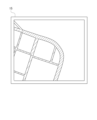
図2は広域地図、図3はその一部を拡大した詳細地図である。詳細地図では、設定範囲と区画領域とが合致している。設定範囲毎に、算出されて補正された指標値に基づいて走行シビアリティを識別可能な表示を行う。 FIG. 2 is a wide area map, and FIG. 3 is a partially enlarged detailed map. In the detailed map, the set range and the block area match. For each set range, a display that allows identification of the driving severity is performed based on the calculated and corrected index value.
例えば、指標値が大きい、つまりタイヤの摩耗量が大きいと判断される範囲では地図の背景色を「赤」などとし、指標値が小さくなるに従って背景色を薄くしたり、背景色を他の色としたりすることができる。背景色を徐々に薄くする場合、指標値の違いを濃淡の違いとして表現できる。色彩を変更する場合、指標値の違いによる複数の範囲を設定し(0~100,100~200など)、範囲毎に異なる色彩を設定する。そして、各区画領域の指標値がいずれの範囲に属するのかで、画面上に表示する色彩を変更すればよい。図3では、ハッチングの間隔の違いにより背景色の濃淡が相違していることを示している。 For example, if the index value is large, that is, in a range where it is judged that the amount of tire wear is large, the background color of the map is set to "red", etc., and as the index value decreases, the background color is made lighter, or the background color is changed to another color. and can be When the background color is gradually lightened, the difference in index values can be expressed as a difference in gradation. When changing the color, a plurality of ranges (0 to 100, 100 to 200, etc.) are set according to different index values, and a different color is set for each range. Then, the color displayed on the screen may be changed depending on which range the index value of each divided area belongs to. FIG. 3 shows that the shades of the background colors are different due to the difference in hatching intervals.
また、地図を縮小して広域を表示させるのであれば、自動的に設定範囲を拡大するようにしてもよい。この場合、設定範囲には複数の区画領域が含まれるので、これら全ての区画領域の指標値を平均すればよい。設定範囲内の全ての走行情報から指標値を算出し直すこともできる。図2では、各設定範囲に複数(4つ)の区画領域が含まれており、それら区画領域の指標値の平均値に基づいて設定範囲における走行シビアリティが識別可能に表示されている。ハッチングの間隔が狭くなっている設定範囲が背景色の濃淡が濃いところであり、指標値が大きくなっている。ハッチングの間隔が広くなるに従って濃淡が薄くなり、指標値が小さくなっていることを示している。 Moreover, if the map is reduced to display a wide area, the set range may be automatically expanded. In this case, since the set range includes a plurality of divided areas, the index values of all these divided areas should be averaged. It is also possible to recalculate the index value from all travel information within the set range. In FIG. 2, each set range includes a plurality (four) of divided areas, and the driving severity in the set range is displayed so as to be identifiable based on the average value of the index values of these divided areas. The setting range where the hatching interval is narrower is where the background color is darker, and the index value is larger. As the hatching interval widens, the shading becomes lighter, indicating that the index value is smaller.
地図上での走行シビアリティの識別可能な表示は、道路単位で行うこともできる。図4では、道路単位で走行シビアリティを識別表示している。前記同様、図中、ハッチングの間隔が狭くなるに従って濃淡が濃くなっており、走行シビアリティとしての指標値が大きくなっていることを示している。 The identifiable display of driving severity on the map can also be done on a road-by-road basis. In FIG. 4, the driving severity is identified and displayed for each road. In the same manner as described above, in the figure, the narrower the hatching interval, the darker the shade, indicating that the index value as the driving severity increases.
第2記憶部14に蓄積される走行情報は国単位で管理するようにしてもよい。例えば、各国での道路事情(路面粗さや道路交通法の違いなど)を考慮することができる。路面粗さなどは国毎に大きく相違する。このため、車両の速度や加速度は同じでもタイヤの摩耗状態は大きく異なる。そこで、国毎に走行情報に対する補正係数を相違させるようにすればよい。また、画面に表示する地図は、国毎に表示方法を異ならせるようにしてもよい。
The travel information stored in the
なお、本発明は、前記実施形態に記載された構成に限定されるものではなく、種々の変更が可能である。 The present invention is not limited to the configurations described in the above embodiments, and various modifications are possible.
前記実施形態では、得られた走行情報に基づいてタイヤの摩耗量を予測する例について説明したが、これに限らず、他の情報を予測するようにしてもよい。例えば、車両がカーブを走行する場合などの情報に基づいてタイヤの偏摩耗量を予測するようにしてもよい。 In the above embodiment, an example of predicting the amount of tire wear based on the obtained travel information has been described, but the present invention is not limited to this, and other information may be predicted. For example, the amount of uneven tire wear may be predicted based on information such as when the vehicle travels on a curve.
また、図5を参照して、クライアント装置1は、最低限の計測機能のみを有するように、受信部4、計測部5、および第1通信部9のみを有してもよい。この場合、クライアント装置1から省略された第1記憶部6、第1表示部7、および第1処理部8は、サーバ装置3が有してもよい。
Also, referring to FIG. 5, the
図5では、第1記憶部6および第2記憶部14と、第1表示部7および第2表示部15と、第1処理部8および第2処理部16とを、サーバ装置3においてそれぞれ同一のブロックで示しているが、その態様は特に限定されない。例えば、第1記憶部6、第1表示部7、および第1処理部8と、第2記憶部14、第2表示部15、および第2処理部16とをそれぞれ別のサーバ装置が有してもよい。
In FIG. 5, the
図5に示すように、クライアント装置1に最低限の計測機能のみを持たせるようにすることで、クライアント装置1を小型化することができる。
As shown in FIG. 5, the
1…クライアント装置
2…通信ネットワーク
3…サーバ装置
4…受信部
5…計測部
6…第1記憶部
7…第1表示部
8…第1処理部
9…第1通信部
10…速度センサ
11…加速度センサ
12…方位センサ
13…第2通信部
14…第2記憶部
15…第2表示部
16…第2処理部
DESCRIPTION OF
Claims (7)
車両の位置情報とタイヤ回転数を含む走行情報とを互いに関連付ける第2ステップと、
前記第2ステップで得られた情報を記憶する第3ステップと、
前記第3ステップで蓄積された情報に基づいて、前記区画領域単位で前記走行情報の指標値である摩擦エネルギーを算出する第4ステップと、
前記第4ステップで算出した指標値を走行シビアリティとして画面上に表示した地図で前記区画領域毎に識別可能に表示する第5ステップと、
を実行する、車両走行条件評価方法。 a first step of dividing stored map information into a plurality of partitioned areas;
a second step of associating the position information of the vehicle with the driving information including the tire rotation speed ;
a third step of storing the information obtained in the second step;
a fourth step of calculating frictional energy, which is an index value of the travel information, for each of the divided areas based on the information accumulated in the third step;
a fifth step of displaying the index value calculated in the fourth step as the driving severity on a map displayed on the screen so that each of the divided areas can be identified;
A vehicle driving condition evaluation method that performs
前記第4ステップでは、設定された区画領域単位で前記走行情報の指標値を算出可能である、請求項1に記載の車両走行条件評価方法。 In the first step, the partitioned area can be arbitrarily set,
2. The vehicle traveling condition evaluation method according to claim 1, wherein, in said fourth step, the index value of said traveling information can be calculated in units of set divided areas.
車両の走行情報としてタイヤ回転数を計測する速度センサーと、
地図情報と、前記地図情報に基づいて画面上に表示する地図を分割してなる複数の区画領域と、互いに関連付けた前記位置情報及び前記タイヤ回転数とを記憶する記憶部と、
前記記憶部に記憶した地図情報に基づいて地図を表示する表示部と、
前記記憶部に記憶された前記位置情報及び前記タイヤ回転数に基づいて前記各区画領域の指標値である摩擦エネルギーを算出し、前記受信部で検出された位置情報に基づいて、算出した前記指標値を走行シビアリティとして前記表示部に表示した地図中に識別可能に表示させる処理部と、
を備える車両走行条件評価システム。 a receiving unit that detects vehicle position information;
A speed sensor that measures the number of tire revolutions as vehicle running information,
a storage unit that stores map information, a plurality of partitioned areas obtained by dividing a map displayed on a screen based on the map information, and the position information and the tire rotation speed that are associated with each other;
a display unit for displaying a map based on the map information stored in the storage unit;
Frictional energy, which is an index value for each of the divided areas, is calculated based on the position information and the tire rotation speed stored in the storage unit, and the calculated index is calculated based on the position information detected by the reception unit. a processing unit that identifiably displays the value as driving severity in the map displayed on the display unit;
A vehicle driving condition evaluation system comprising:
Priority Applications (4)
| Application Number | Priority Date | Filing Date | Title |
|---|---|---|---|
| JP2019179950A JP7306943B2 (en) | 2019-09-30 | 2019-09-30 | VEHICLE RUNNING CONDITION EVALUATION METHOD AND SYSTEM |
| US16/992,548 US20210095991A1 (en) | 2019-09-30 | 2020-08-13 | Vehicle traveling condition evaluation method and system |
| CN202010818788.2A CN112581649A (en) | 2019-09-30 | 2020-08-14 | Vehicle driving condition evaluation method and system |
| DE102020123552.6A DE102020123552A1 (en) | 2019-09-30 | 2020-09-09 | Vehicle traveling condition evaluation method and system |
Applications Claiming Priority (1)
| Application Number | Priority Date | Filing Date | Title |
|---|---|---|---|
| JP2019179950A JP7306943B2 (en) | 2019-09-30 | 2019-09-30 | VEHICLE RUNNING CONDITION EVALUATION METHOD AND SYSTEM |
Publications (2)
| Publication Number | Publication Date |
|---|---|
| JP2021056114A JP2021056114A (en) | 2021-04-08 |
| JP7306943B2 true JP7306943B2 (en) | 2023-07-11 |
Family
ID=74873142
Family Applications (1)
| Application Number | Title | Priority Date | Filing Date |
|---|---|---|---|
| JP2019179950A Active JP7306943B2 (en) | 2019-09-30 | 2019-09-30 | VEHICLE RUNNING CONDITION EVALUATION METHOD AND SYSTEM |
Country Status (4)
| Country | Link |
|---|---|
| US (1) | US20210095991A1 (en) |
| JP (1) | JP7306943B2 (en) |
| CN (1) | CN112581649A (en) |
| DE (1) | DE102020123552A1 (en) |
Citations (15)
| Publication number | Priority date | Publication date | Assignee | Title |
|---|---|---|---|---|
| JP2006521237A (en) | 2003-03-21 | 2006-09-21 | ダイムラークライスラー・アクチェンゲゼルシャフト | Method and apparatus for determining a friction value representative of friction acting between a road and a vehicle tire |
| JP2010020430A (en) | 2008-07-09 | 2010-01-28 | Fuji Heavy Ind Ltd | Road surface slipperiness determination system |
| JP2010095135A (en) | 2008-10-16 | 2010-04-30 | Toyota Motor Corp | Wheel vibration extraction device and road surface state estimation device |
| JP2010204095A (en) | 2009-02-06 | 2010-09-16 | Yokohama Rubber Co Ltd:The | Device and method for evaluation of antiwear performance, and computer program therefor |
| JP2011149879A (en) | 2010-01-22 | 2011-08-04 | Yokohama Rubber Co Ltd:The | Using condition evaluation method and device of tire, and abrasion predicting method and device of the tire |
| JP2011148465A (en) | 2010-01-25 | 2011-08-04 | Yokohama Rubber Co Ltd:The | Method of predicting physical quantity which tire ground surface receives from road surface, method of predicting tire wear, device of predicting tire wear, and program |
| JP2012155286A (en) | 2011-01-28 | 2012-08-16 | Hitachi Automotive Systems Ltd | Map data distribution server and map data distribution method |
| JP2015229433A (en) | 2014-06-05 | 2015-12-21 | 太平洋工業株式会社 | Road surface condition detection device and road surface condition detection system |
| JP2016011867A (en) | 2014-06-27 | 2016-01-21 | Kyb株式会社 | Road surface condition determination system |
| JP2016075575A (en) | 2014-10-06 | 2016-05-12 | 株式会社ブリヂストン | Road surface state discrimination system |
| JP2016095184A (en) | 2014-11-13 | 2016-05-26 | 大日本印刷株式会社 | Telematics system |
| JP2016194867A (en) | 2015-04-01 | 2016-11-17 | トヨタ自動車株式会社 | Traveling environment evaluation system |
| JP2017156295A (en) | 2016-03-04 | 2017-09-07 | 三菱重工業株式会社 | Tire wear life estimation system |
| JP2019044538A (en) | 2017-09-06 | 2019-03-22 | 日立建機株式会社 | Road surface status arithmetic unit and road surface management system for mine |
| JP2019105600A (en) | 2017-12-14 | 2019-06-27 | 株式会社ブリヂストン | Wear amount prediction method, wear amount prediction device, and wear amount prediction program |
Family Cites Families (2)
| Publication number | Priority date | Publication date | Assignee | Title |
|---|---|---|---|---|
| JP2015051704A (en) * | 2013-09-06 | 2015-03-19 | 株式会社デンソー | Drive support apparatus |
| FR3045815A1 (en) * | 2015-12-17 | 2017-06-23 | Michelin & Cie | METHOD FOR CARTOGRAPHIC REPRESENTATION OF DATA CONCERNING THE STATUS OF A ROAD |
-
2019
- 2019-09-30 JP JP2019179950A patent/JP7306943B2/en active Active
-
2020
- 2020-08-13 US US16/992,548 patent/US20210095991A1/en not_active Abandoned
- 2020-08-14 CN CN202010818788.2A patent/CN112581649A/en active Pending
- 2020-09-09 DE DE102020123552.6A patent/DE102020123552A1/en not_active Withdrawn
Patent Citations (15)
| Publication number | Priority date | Publication date | Assignee | Title |
|---|---|---|---|---|
| JP2006521237A (en) | 2003-03-21 | 2006-09-21 | ダイムラークライスラー・アクチェンゲゼルシャフト | Method and apparatus for determining a friction value representative of friction acting between a road and a vehicle tire |
| JP2010020430A (en) | 2008-07-09 | 2010-01-28 | Fuji Heavy Ind Ltd | Road surface slipperiness determination system |
| JP2010095135A (en) | 2008-10-16 | 2010-04-30 | Toyota Motor Corp | Wheel vibration extraction device and road surface state estimation device |
| JP2010204095A (en) | 2009-02-06 | 2010-09-16 | Yokohama Rubber Co Ltd:The | Device and method for evaluation of antiwear performance, and computer program therefor |
| JP2011149879A (en) | 2010-01-22 | 2011-08-04 | Yokohama Rubber Co Ltd:The | Using condition evaluation method and device of tire, and abrasion predicting method and device of the tire |
| JP2011148465A (en) | 2010-01-25 | 2011-08-04 | Yokohama Rubber Co Ltd:The | Method of predicting physical quantity which tire ground surface receives from road surface, method of predicting tire wear, device of predicting tire wear, and program |
| JP2012155286A (en) | 2011-01-28 | 2012-08-16 | Hitachi Automotive Systems Ltd | Map data distribution server and map data distribution method |
| JP2015229433A (en) | 2014-06-05 | 2015-12-21 | 太平洋工業株式会社 | Road surface condition detection device and road surface condition detection system |
| JP2016011867A (en) | 2014-06-27 | 2016-01-21 | Kyb株式会社 | Road surface condition determination system |
| JP2016075575A (en) | 2014-10-06 | 2016-05-12 | 株式会社ブリヂストン | Road surface state discrimination system |
| JP2016095184A (en) | 2014-11-13 | 2016-05-26 | 大日本印刷株式会社 | Telematics system |
| JP2016194867A (en) | 2015-04-01 | 2016-11-17 | トヨタ自動車株式会社 | Traveling environment evaluation system |
| JP2017156295A (en) | 2016-03-04 | 2017-09-07 | 三菱重工業株式会社 | Tire wear life estimation system |
| JP2019044538A (en) | 2017-09-06 | 2019-03-22 | 日立建機株式会社 | Road surface status arithmetic unit and road surface management system for mine |
| JP2019105600A (en) | 2017-12-14 | 2019-06-27 | 株式会社ブリヂストン | Wear amount prediction method, wear amount prediction device, and wear amount prediction program |
Also Published As
| Publication number | Publication date |
|---|---|
| JP2021056114A (en) | 2021-04-08 |
| US20210095991A1 (en) | 2021-04-01 |
| CN112581649A (en) | 2021-03-30 |
| DE102020123552A1 (en) | 2021-04-01 |
Similar Documents
| Publication | Publication Date | Title |
|---|---|---|
| CN107735300B (en) | Method for determining a speed limit for a vehicle | |
| CN110832281A (en) | Road condition monitoring | |
| EP1767422B1 (en) | Method and apparatus for evaluating a cornering stability of a wheel | |
| US11458776B2 (en) | Tread wear monitoring system and method | |
| US20160200155A1 (en) | Method and System for Determining a Pressure Deviation Between a Setpoint Tire Pressure and an Actual Tire Pressure for a Tire of a Vehicle as Well as for Determining a Wheel Load | |
| CN111201173B (en) | Method for determining a friction value of a contact between a vehicle tire and a lane and method for controlling a vehicle function of a vehicle | |
| CN104691550A (en) | Determining a risk of aquaplaning | |
| JP5172507B2 (en) | Road slipperiness judgment system | |
| JP4737006B2 (en) | Vehicle running state monitoring device | |
| JP6815406B2 (en) | Speed calculator, control method, program and storage medium | |
| US20200380805A1 (en) | System for determining tire state | |
| US11061129B2 (en) | Distance estimation device, distance estimation method and program | |
| US20190219399A1 (en) | Travel distance calculation device, charging system, travel distance calculation method, program, and storage medium | |
| JP7306943B2 (en) | VEHICLE RUNNING CONDITION EVALUATION METHOD AND SYSTEM | |
| KR102034664B1 (en) | Map Matching System and Method Using Tire Pressure Monitoring System | |
| US20150161824A1 (en) | Indirect characterization of transportation networks and vehicle health | |
| US20210183187A1 (en) | Vehicle driving condition evaluation method and system | |
| JP2023020492A (en) | Tire damage accumulation amount estimation system, arithmetic model generation system and tire damage accumulation amount estimation method | |
| US20190011282A1 (en) | Distance estimation device, distance estimation method and program | |
| JP7388000B2 (en) | Road surface friction coefficient prediction system | |
| JP7338240B2 (en) | Tire condition determination system | |
| JP7456749B2 (en) | Wear amount estimation system and calculation model generation system | |
| WO2023153434A1 (en) | Road surface evaluation device | |
| WO2023042791A1 (en) | Lane estimation device and lane estimation method | |
| WO2012025128A1 (en) | Method for calibrating an inclination sensor and inclination sensor system |
Legal Events
| Date | Code | Title | Description |
|---|---|---|---|
| A621 | Written request for application examination |
Free format text: JAPANESE INTERMEDIATE CODE: A621 Effective date: 20220713 |
|
| A977 | Report on retrieval |
Free format text: JAPANESE INTERMEDIATE CODE: A971007 Effective date: 20230421 |
|
| A131 | Notification of reasons for refusal |
Free format text: JAPANESE INTERMEDIATE CODE: A131 Effective date: 20230509 |
|
| A521 | Request for written amendment filed |
Free format text: JAPANESE INTERMEDIATE CODE: A523 Effective date: 20230609 |
|
| TRDD | Decision of grant or rejection written | ||
| A01 | Written decision to grant a patent or to grant a registration (utility model) |
Free format text: JAPANESE INTERMEDIATE CODE: A01 Effective date: 20230627 |
|
| A61 | First payment of annual fees (during grant procedure) |
Free format text: JAPANESE INTERMEDIATE CODE: A61 Effective date: 20230629 |
|
| R150 | Certificate of patent or registration of utility model |
Ref document number: 7306943 Country of ref document: JP Free format text: JAPANESE INTERMEDIATE CODE: R150 |