JP7301602B2 - game machine - Google Patents
game machine Download PDFInfo
- Publication number
- JP7301602B2 JP7301602B2 JP2019099165A JP2019099165A JP7301602B2 JP 7301602 B2 JP7301602 B2 JP 7301602B2 JP 2019099165 A JP2019099165 A JP 2019099165A JP 2019099165 A JP2019099165 A JP 2019099165A JP 7301602 B2 JP7301602 B2 JP 7301602B2
- Authority
- JP
- Japan
- Prior art keywords
- movable body
- state
- game
- movable
- guide
- Prior art date
- Legal status (The legal status is an assumption and is not a legal conclusion. Google has not performed a legal analysis and makes no representation as to the accuracy of the status listed.)
- Active
Links
Images


Classifications
-
- Y—GENERAL TAGGING OF NEW TECHNOLOGICAL DEVELOPMENTS; GENERAL TAGGING OF CROSS-SECTIONAL TECHNOLOGIES SPANNING OVER SEVERAL SECTIONS OF THE IPC; TECHNICAL SUBJECTS COVERED BY FORMER USPC CROSS-REFERENCE ART COLLECTIONS [XRACs] AND DIGESTS
- Y02—TECHNOLOGIES OR APPLICATIONS FOR MITIGATION OR ADAPTATION AGAINST CLIMATE CHANGE
- Y02E—REDUCTION OF GREENHOUSE GAS [GHG] EMISSIONS, RELATED TO ENERGY GENERATION, TRANSMISSION OR DISTRIBUTION
- Y02E60/00—Enabling technologies; Technologies with a potential or indirect contribution to GHG emissions mitigation
- Y02E60/10—Energy storage using batteries
Description
本発明は、遊技が可能な遊技機に関する。 The present invention relates to a game machine capable of playing games.
遊技機の一例であるパチンコ遊技機やスロットマシンにおいて、第1位置から該第1位置より下方の第2位置へ自重により落下可能な可動体を備えたもの等があった(例えば、特許文献1参照)。
Pachinko game machines and slot machines, which are examples of game machines, have a movable body that can fall from a first position to a second position below the first position by its own weight (for example,
さらに、遊技機の一例であるパチンコ遊技機やスロットマシンにおいて、第1状態と該第1状態とは異なる第2状態とに変化可能な可動体を備えた遊技機があった。この種の遊技機として、例えば、可動体は、動作可能な本体部と、該本体部に軸支され、第1状態において可動体の本体部の背面側に収容されることで該本体部により被覆され、第2状態において可動体の本体部の周囲に突出することで該本体部により被覆されない開閉部(特定部)と、からなるもの等があった(例えば、特許文献2参照)。 Further, among pachinko game machines and slot machines, which are examples of game machines, there are game machines having a movable body that can change between a first state and a second state different from the first state. In this type of game machine, for example, a movable body is pivotally supported by a operable main body, and is housed on the back side of the main body of the movable body in the first state, thereby There is a device including an opening/closing portion (specific portion) that is covered and protrudes around the body portion of the movable body in the second state so as not to be covered by the body portion (see, for example, Patent Document 2 ).
上記特許文献1に記載の遊技機では、可動体の動作に応じて連動する演出部といった連動部を備えるものの場合、可動体が第2位置に落下した衝撃により連動部が破損するなど不具合が生じる虞があるという問題があった。
In the game machine described in
本発明は、このような問題点に着目してなされたもので、可動体が落下した衝撃により不具合が発生することを抑制できる遊技機を提供することを目的とする。 SUMMARY OF THE INVENTION It is an object of the present invention to provide a game machine capable of suppressing the occurrence of problems caused by the impact of falling movable bodies .
手段Aの遊技機は、
遊技が可能な遊技機(例えば、パチンコ遊技機1)であって、
第1位置(例えば、第3原点位置)から該第1位置より下方の第2位置(例えば、第3演出位置)へ自重により落下可能な可動体(例えば、第3可動体502)を備え、
前記可動体は、
装飾部と、
前記可動体の前記第1位置から前記第2位置への落下に応じて、前記装飾部との位置関係が変化するように移動する連動部(例えば、ガイド軸549A~549D、ガイド軸572L,572R、回動軸571)と、
一端部と他端部とを有し、前記一端部と前記他端部との間で前記連動部の移動を案内する案内部(例えば、長孔547A~547D、長孔563A~563D、長孔573L,573R、長孔565)と、
を含み、
前記連動部には、特定連動部と、所定連動部と、があり、
前記案内部には、前記特定連動部の移動を案内する特定案内部と、前記所定連動部の移動を案内する所定案内部と、があり、
前記連動部は、前記可動体の前記第1位置から前記第2位置への落下に応じて前記案内部の前記一端部側から前記他端部側に移動し、
前記特定連動部は、少なくとも前記可動体が前記第2位置まで落下して該第2位置にて移動が規制されたときに、前記特定案内部の前記他端部に当接するように設けられ、
前記所定連動部は、少なくとも前記可動体が前記第2位置まで落下して該第2位置にて移動が規制されたときに、前記所定案内部の前記他端部に当接しないように設けられ(例えば、第3可動体502が第3演出位置に到達したとき、第1可動部532A,532Bのガイド軸549A,549Bは、スライド部材534L,534Rの長孔563A,563B及びベース部531の長孔547A,547Bの上端側に位置しているが、上端に対し長さL12だけ離間しており(図25(B)参照)、第1可動部532C,532Dのガイド軸549C,549Dは、スライド部材534L,534Rの長孔563C,563D及びベース部531の長孔547C,547Dの下端側に位置しているが、特に図示しないが、下端に対し長さL12だけ離間している(図25(B)参照)。)、
前記特定連動部及び前記特定案内部は、前記所定連動部及び前記所定案内部よりも強度が高い、
ことを特徴としている。
この特徴によれば、可動体が第2位置まで落下したときに所定連動部は所定案内部の他端部と当接しないので、落下により所定連動部が所定案内部の他端部に勢いよく衝突して所定案内部や所定連動部が破損することや大きな衝突音が発生することを抑制することができる。
一方、上記特許文献2に記載の遊技機では、可動体が第2状態に変化して開閉部が本体部の周囲に突出したときに、円形の装飾部位と一緒に棒状の非装飾部位も遊技者から視認可能となるため、演出効果が低下する虞があるという問題があった。このような問題点に着目し、演出効果の低下を抑制することができる遊技機を提供することも求められている。
手段1の遊技機は、
遊技が可能な遊技機(例えば、パチンコ遊技機1)であって、
第1状態(図13(A)参照)と該第1状態とは異なる第2状態(図13(B)参照)とに変化可能な第1可動体(例えば、第1可動体302)と、
前記第1可動体の前面側に移動可能な第2可動体(例えば、第3可動体502)と、
を備え、
前記第1可動体は、
前記第1状態において視認困難である一方で、前記第2状態において視認容易である特定部(例えば、ベース部331の前面や回動用モータ350など)を有し、
前記第2可動体が該第1可動体の前記特定部の前面側に重複しているときに前記第2状態に変化可能である(例えば、第1可動体302は、第3可動体502が第3演出位置まで移動して第1可動体302の前面側に重複しているときに第2状態に変化することで、可動部332L,332Rの当接辺332Aと当接辺332Bとが離れてベース部331の前面中央部や回動用モータ350の前面側が開放されることになるが、その前方に位置する第3可動体502により被覆されることで、パチンコ遊技機1の前方に位置する遊技者からはベース部331の前面中央部や回動用モータ350を視認し難くなる。図30(B)参照)
ことを特徴としている。
この特徴によれば、第1可動体は特定部の前面側に第2可動体が重複しているときに第2状態に変化することで、遊技者から特定部を視認し難くすることができるため、第2可動体を利用して第1可動体の演出効果の低下を抑制することができる。
The game machine of means A is
A gaming machine (for example, a pachinko gaming machine 1) capable of playing a game,
A movable body (e.g., third movable body 502) capable of falling by its own weight from a first position (e.g. , third origin position) to a second position (e.g., third rendering position) below the first position;
The movable body is
decoration and
Interlocking parts (for example,
Guide portions (for example,
including
The interlocking portion includes a specific interlocking portion and a predetermined interlocking portion,
The guide section includes a specific guide section that guides movement of the specific interlocking section and a predetermined guide section that guides movement of the predetermined interlock section,
the interlocking part moves from the one end side of the guide part to the other end side in accordance with the drop of the movable body from the first position to the second position;
The specific interlocking part is provided so as to contact the other end of the specific guide part at least when the movable body falls to the second position and movement is restricted at the second position,
The predetermined interlocking portion is provided so as not to come into contact with the other end portion of the predetermined guide portion at least when the movable body falls to the second position and its movement is restricted at the second position. (For example, when the third
The specific interlocking portion and the specific guide portion are stronger than the predetermined interlocking portion and the predetermined guide portion,
It is characterized by
According to this feature, when the movable body drops to the second position, the predetermined interlocking portion does not abut against the other end of the predetermined guide portion, so that the predetermined interlocking portion moves vigorously toward the other end of the predetermined guide portion upon dropping. It is possible to suppress damage to the predetermined guide portion and the predetermined interlocking portion due to collision and generation of a loud collision sound.
On the other hand, in the game machine described in
The game machine of
A gaming machine (for example, a pachinko gaming machine 1) capable of playing a game,
a first movable body (for example, a first movable body 302) that can change between a first state (see FIG. 13A) and a second state (see FIG. 13B) different from the first state;
a second movable body (for example, a third movable body 502) movable to the front side of the first movable body;
with
The first movable body is
Having a specific portion (for example, the front surface of the
When the second movable body overlaps the front side of the specific portion of the first movable body, it can be changed to the second state (for example, the first
It is characterized by
According to this feature, the first movable body changes to the second state when the second movable body overlaps the front side of the specific part, thereby making it difficult for the player to visually recognize the specific part. Therefore, it is possible to use the second movable body to suppress the deterioration of the rendering effect of the first movable body.
手段2の遊技機は、手段1に記載の遊技機であって、
前記第1可動体(例えば、第1可動体302)は、動作することにより該第1可動体を前記第1状態と前記第2状態とに変化させる可動部(例えば、可動部332L,332R)を有し、
前記特定部は、前記可動部を駆動するための駆動手段(例えば、回動用モータ350)である
ことを特徴としている。
この特徴によれば、可動部を動作させるための駆動手段を遊技者から視認し難くしつつ、第1可動体を好適なタイミングで第2状態に変化させることができる。
The gaming machine of
The first movable body (for example, the first movable body 302) operates to change the first movable body between the first state and the second state (for example,
It is characterized in that the specifying unit is driving means (for example, rotation motor 350) for driving the movable unit.
According to this feature, it is possible to change the first movable body to the second state at a suitable timing while making it difficult for the player to visually recognize the drive means for operating the movable part.
手段3の遊技機は、手段2に記載の遊技機であって、
前記第1可動体(例えば、第1可動体302)は、第1位置(例えば、第1原点位置)から該第1位置とは異なる第2位置(例えば、第2原点位置)へ自重により落下可能であるとともに、前記第2位置において前記第2状態に変形可能であり(図30(B)参照)、
前記駆動手段の動力を前記可動部に伝達する複数の伝達部材(例えば、リンク部材352A,352B、リンク部材353L,353R、など)を有し、
前記複数の伝達部材は、前記可動部が前記第1状態から前記第2状態に変化するときに上方向に移動する所定伝達部材(例えば、リンク部材352A,352B)を含む
ことを特徴としている。
この特徴によれば、複数の伝達部材のうち所定伝達部材は、第1可動体が第2位置に落下したときに上方に移動し難いため、第1可動体が落下した衝撃により可動部が第1状態から第2状態に変化してしまうことを抑制できる。
The gaming machine of
The first movable body (eg, first movable body 302) falls from a first position (eg, first origin position) to a second position (eg, second origin position) different from the first position by its own weight. capable of being deformed into the second state at the second position (see FIG. 30(B)),
having a plurality of transmission members (for example,
The plurality of transmission members include predetermined transmission members (for example,
According to this feature, it is difficult for the predetermined transmission member among the plurality of transmission members to move upward when the first movable body drops to the second position. It is possible to suppress the change from the 1st state to the 2nd state.
手段4の遊技機は、手段1~3のいずれかに記載の遊技機であって、
前記第1可動体(例えば、第1可動体302)は、第1位置(例えば、第1原点位置)から該第1位置とは異なる第2位置(例えば、第2原点位置)との間で移動可能であり、
前記第2可動体(例えば、第3可動体502)は、前記第1可動体が前記第2位置に位置しているときに前記第1可動体の前面側に移動可能であり(図30(B)参照)、
前記第2位置において前記第1可動体の前記第2状態への変化を許容する一方で、前記第1位置において前記可動体の前記第2状態への変化を規制する規制手段(例えば、突出部311L,311Rの湾曲壁部311A,311Bなど)を備える(図13(A)参照)
ことを特徴としている。
この特徴によれば、第1可動体が第1位置において意図せずに第1状態から第2状態に変化することを防止できる。
The gaming machine of means 4 is the gaming machine according to any one of
The first movable body (eg, first movable body 302) moves from a first position (eg, first origin position) to a second position (eg, second origin position) different from the first position. is movable and
The second movable body (for example, the third movable body 502) can move to the front side of the first movable body when the first movable body is positioned at the second position (see FIG. 30 ( B) see),
While allowing the first movable body to change to the second state at the second position, restricting means (for example, a projecting portion) for restricting the movable body from changing to the second state at the first position
It is characterized by
According to this feature, it is possible to prevent the first movable body from unintentionally changing from the first state to the second state at the first position.
手段5の遊技機は、手段1~4のいずれかに記載の遊技機であって、
前記第1可動体(例えば、第1可動体302)は、前記第1位置(例えば、第1原点位置)から該第1位置よりも下方の前記第2位置(例えば、第2原点位置)へ自重により落下可能であり、
前記第2可動体(例えば、第3可動体502)は、前記第1位置の前面側の第3位置(例えば、第3原点位置)から前記第2位置の前面側の第4位置(例えば、第3演出位置)へ自重により落下可能であり、
前記第1可動体を前記第1位置にて保持する保持状態と該第1位置に保持しない解除状態とに変化可能な第1保持手段(例えば、演出用ソレノイド304L,304R)と、
前記第2可動体を前記第3位置にて保持する保持状態と該第3位置に保持しない解除状態とに変化可能な第2保持手段(例えば、演出用ソレノイド504L,504R)と、
前記第1保持手段を前記保持状態から前記解除状態へ変化させる制御と前記第2保持手段を前記保持状態から前記解除状態へ変化させる制御とを別個に実行可能な制御手段(例えば、原点位置から演出位置まで自重により落下可能な第1可動体302と第3可動体502は、原点位置においてそれぞれ別個の保持手段(係止部材304D,504D)により保持されていることで、演出制御用CPU120は第1可動体302と第3可動体502を個別に落下させることが可能である)と、
を備える
ことを特徴としている。
この特徴によれば、第1可動体と第2可動体とを別個のタイミングで落下させることができるため、演出態様の多様化を図ることができる。
The gaming machine of
The first movable body (eg, first movable body 302) moves from the first position (eg, first origin position) to the second position (eg, second origin position) below the first position. It can fall by its own weight,
The second movable body (for example, the third movable body 502) moves from a third position (for example, a third origin position) on the front side of the first position to a fourth position on the front side of the second position (for example, 3rd production position) can be dropped by its own weight,
first holding means (for example,
second holding means (for example,
Control means (for example, from the origin position) capable of separately executing control for changing the first holding means from the holding state to the released state and control for changing the second holding means from the holding state to the released state The first
It is characterized by having
According to this feature, since the first movable body and the second movable body can be dropped at different timings, it is possible to diversify the mode of presentation.
尚、本発明は、本発明の請求項に記載された発明特定事項のみを有するものであっても良いし、本発明の請求項に記載された発明特定事項とともに該発明特定事項以外の構成を有するものであっても良い。 The present invention may include only the matters specifying the invention described in the claims of the present invention, or may include the matters specifying the invention described in the claims of the present invention together with the matters specifying the invention other than the matters specifying the invention. It may have.
(パチンコ遊技機1の構成等)
図1は、パチンコ遊技機1の正面図であり、主要部材の配置レイアウトを示す。パチンコ遊技機(遊技機)1は、大別して、遊技盤面を構成する遊技盤(ゲージ盤)2と、遊技盤2を支持固定する遊技機用枠(台枠)3とから構成されている。遊技盤2には、遊技領域10が形成され、この遊技領域10には、遊技媒体としての遊技球が、所定の打球発射装置から発射されて打ち込まれる。また、遊技機用枠3には、ガラス窓50aを有するガラス扉枠50が左側辺を中心として回動可能に設けられ、該ガラス扉枠50により遊技領域10を開閉できるようになっており、ガラス扉枠50を閉鎖したときにガラス窓50aを通して遊技領域10を透視できるようになっている。
(Structure of
FIG. 1 is a front view of the
図1に示すように、遊技盤2は、アクリル樹脂、ポリカーボネート樹脂、メタクリル樹脂等の透光性を有する合成樹脂材にて正面視略四角形状に形成され、前面である遊技盤面に障害釘(図示略)やガイドレール2b等が設けられた盤面板と、該盤面板の背面側に一体的に取付けられるスペーサ部材と、から構成されている。尚、遊技盤2は、ベニヤ板等の非透光性部材にて正面視略四角形状に構成され、前面である遊技盤面に障害釘(図示略)やガイドレール2b等が設けられた盤面板にて構成されていてもよい。
As shown in FIG. 1, the
遊技盤2の所定位置(図1に示す例では、遊技領域10の右側方)には、複数種類の特別識別情報としての特別図柄(特図ともいう。)の可変表示(特図ゲームともいう)を行う、第1特別図柄表示装置4Aと、第2特別図柄表示装置4Bとが設けられている。これらは、7セグメントのLED(light emitting diode)などからなり、特別図柄は、「0」~「9」を示す数字や「-」などの点灯パターンなどであればよい。特別図柄には、LEDを全て消灯したパターンが含まれてもよい。
At a predetermined position of the game board 2 (on the right side of the
尚、特別図柄の「可変表示」とは、例えば、複数種類の特別図柄を変動可能に表示することである(後述の他の図柄についても同じ)。変動としては、複数の図柄の更新表示、複数の図柄のスクロール表示、1以上の図柄の変形、1以上の図柄の拡大/縮小などがある。特別図柄や後述の普通図柄の変動では、複数種類の特別図柄又は普通図柄が更新表示される。後述の飾り図柄の変動では、複数種類の飾り図柄がスクロール表示又は更新表示されたり、1以上の飾り図柄が変形や拡大/縮小されたりする。尚、変動には、ある図柄を点滅表示する態様も含まれる。可変表示の最後には、表示結果として所定の特別図柄が停止表示(導出又は導出表示などともいう)される(後述の他の図柄の可変表示についても同じ)。尚、可変表示を変動表示、変動と表現する場合がある。 The "variable display" of the special symbols means, for example, that a plurality of types of special symbols are variably displayed (the same applies to other symbols described later). Variations include updating display of a plurality of patterns, scrolling display of a plurality of patterns, deformation of one or more patterns, enlargement/reduction of one or more patterns, and the like. In the variation of special symbols and normal symbols, which will be described later, a plurality of types of special symbols or normal symbols are updated and displayed. In the variation of decorative patterns, which will be described later, a plurality of types of decorative patterns are scrolled or updated, and one or more decorative patterns are deformed or enlarged/reduced. Incidentally, the variation includes a mode of blinking a certain symbol. At the end of the variable display, a predetermined special symbol is stopped and displayed (also referred to as derivation or derivation display) as a display result (the same applies to variable display of other symbols to be described later). Variable display may be expressed as variable display or variation.
尚、第1特別図柄表示装置4Aにおいて可変表示される特別図柄を「第1特図」ともいい、第2特別図柄表示装置4Bにおいて可変表示される特別図柄を「第2特図」ともいう。また、第1特図を用いた特図ゲームを「第1特図ゲーム」といい、第2特図を用いた特図ゲームを「第2特図ゲーム」ともいう。尚、特別図柄の可変表示を行う特別図柄表示装置は1種類であってもよい。
The special symbols variably displayed on the first special
遊技盤2における遊技領域10の中央付近には画像表示装置5が設けられている。画像表示装置5は、例えばLCD(液晶表示装置)や有機EL(Electro Luminescence)等から構成され、各種の演出画像を表示する。画像表示装置5は、プロジェクタ及びスクリーンから構成されていてもよい。画像表示装置5には、各種の演出画像が表示される。尚、遊技盤2における開口2cには枠状のセンター飾り枠51が設けられている。
An
例えば、画像表示装置5の画面上では、第1特図ゲームや第2特図ゲームと同期して、特別図柄とは異なる複数種類の装飾識別情報としての飾り図柄(数字などを示す図柄など)の可変表示が行われる。ここでは、第1特図ゲーム又は第2特図ゲームに同期して、「左」、「中」、「右」の各飾り図柄表示エリア5L、5C、5Rにおいて飾り図柄が可変表示(例えば上下方向のスクロール表示や更新表示)される。尚、同期して実行される特図ゲーム及び飾り図柄の可変表示を総称して単に可変表示ともいう。
For example, on the screen of the
画像表示装置5の画面上には、実行が保留されている可変表示に対応する保留表示や、実行中の可変表示に対応するアクティブ表示を表示するための表示エリア5Hが設けられていてもよい。保留表示及びアクティブ表示を総称して可変表示に対応する可変表示対応表示ともいう。表示エリア5Hには、実行が保留されている第1特図ゲーム(飾り図柄の可変表示)に対応する第1保留表示画像(ここでは、丸の画像)が右詰めで表示され、実行が保留されている第2特図ゲーム(飾り図柄の可変表示)に対応する第2保留表示画像(ここでは、丸の画像)が左詰めで表示される。
A
保留されている可変表示の数は保留記憶数ともいう。第1特図ゲームに対応する保留記憶数を第1保留記憶数、第2特図ゲームに対応する保留記憶数を第2保留記憶数ともいう。また、第1保留記憶数と第2保留記憶数との合計を合計保留記憶数ともいう。 The number of variable representations that are reserved is also referred to as the number of reserved memories. The reserved memory number corresponding to the first special game is also referred to as the first reserved memory number, and the reserved memory number corresponding to the second special game is also referred to as the second reserved memory number. The sum of the first reserved memory count and the second reserved memory count is also referred to as the total reserved memory count.
また、遊技盤2の所定位置には、複数のLEDを含んで構成された第1保留表示器25Aと第2保留表示器25Bとが設けられ、第1保留表示器25Aは、LEDの点灯個数によって、第1保留記憶数を表示し、第2保留表示器25Bは、LEDの点灯個数によって、第2保留記憶数を表示する。
At a predetermined position of the
画像表示装置5の下方には、普通入賞球装置6Aと、普通可変入賞球装置6Bとが設けられている。
Below the
普通入賞球装置6Aは、例えば所定の玉受部材によって常に遊技球が進入可能な一定の開放状態に保たれる第1始動入賞口を形成する。第1始動入賞口に遊技球が進入したときには、所定個(例えば3個)の賞球が払い出されるとともに、第1特図ゲームが開始され得る。
The normal
普通可変入賞球装置6Bは、普通電動役物用のソレノイド81(図2参照)によって第1突出位置となる閉鎖状態と退避位置となる開放状態とに変化する可動板を有する普通電動役物を備え、第2始動入賞口を形成する。普通可変入賞球装置6Bは、例えば、ソレノイド81がオフ状態であるときに可動板が第1突出位置となることにより、当該可動板が遊技領域10側に突出し、第2始動入賞口に遊技球が進入しない閉鎖状態になる(第2始動入賞口が閉鎖状態になるともいう。)。その一方で、普通可変入賞球装置6Bは、ソレノイド81がオン状態であるときに可動板が遊技盤2側に退避する退避位置となることにより、第2始動入賞口に遊技球が進入できる開放状態になる(第2始動入賞口が開放状態になるともいう。)。第2始動入賞口に遊技球が進入したときには、所定個(例えば3個)の賞球が払い出されるとともに、第2特図ゲームが開始され得る。
The normal variable winning
普通入賞球装置6Aと普通可変入賞球装置6Bの間には、大入賞口を有する特別可変入賞球装置7が設けられている。特別可変入賞球装置7は、ソレノイド82(図2参照)によって開閉駆動される大入賞口扉を備え、その大入賞口扉によって開放状態と閉鎖状態とに変化する特定領域としての大入賞口を形成する。
A special variable winning ball device 7 having a large winning hole is provided between the normal
一例として、特別可変入賞球装置7では、大入賞口扉用(特別電動役物用)のソレノイド82がオフ状態であるときに大入賞口扉が大入賞口を閉鎖状態として、遊技球が大入賞口に進入(通過)できなくなる。その一方で、特別可変入賞球装置7では、大入賞口扉用のソレノイド82がオン状態であるときに大入賞口扉が大入賞口を開放状態として、遊技球が大入賞口に進入しやすくなる。
As an example, in the special variable winning ball device 7, when the
大入賞口に遊技球が進入したときには、所定個数(例えば14個)の遊技球が賞球として払い出される。大入賞口に遊技球が進入したときには、例えば第1始動入賞口や第2始動入賞口及び一般入賞口に遊技球が進入したときよりも多くの賞球が払い出される。 When game balls enter the big winning hole, a predetermined number (for example, 14) of game balls are paid out as prize balls. When the game balls enter the big winning hole, more winning balls are paid out than when the game balls enter the first starting winning hole, the second starting winning hole and the general winning hole, for example.
一般入賞口を含む各入賞口に遊技球が進入することを「入賞」ともいう。特に、始動口(第1始動入賞口、第2始動入賞口始動口)への入賞を始動入賞ともいう。 Entering a game ball into each winning hole including general winning holes is also called "winning". In particular, winning a prize to a starting opening (first starting winning opening, second starting winning opening starting opening) is also referred to as starting winning.
遊技盤2の所定位置(図1に示す例では、遊技領域10の左側方)には、普通図柄表示器20が設けられている。一例として、普通図柄表示器20は、7セグメントのLEDなどからなり、特別図柄とは異なる複数種類の普通識別情報としての普通図柄の可変表示を行う。普通図柄は、「0」~「9」を示す数字や「-」などの点灯パターンなどにより表される。普通図柄には、LEDを全て消灯したパターンが含まれてもよい。このような普通図柄の可変表示は、普図ゲームともいう。
A
画像表示装置5の左方には、遊技球が通過可能な通過ゲート41が設けられている。遊技球が通過ゲート41を通過したことに基づき、普図ゲームが実行される。
A
普通図柄表示器20の右方には、普図保留表示器25Cが設けられている。普図保留表示器25Cは、例えば4個のLEDを含んで構成され、実行が保留されている普図ゲームの数である普図保留記憶数をLEDの点灯個数により表示する。
On the right side of the
遊技盤2の表面には、上記の構成以外にも、遊技球の流下方向や速度を変化させる風車及び多数の障害釘が設けられている。遊技領域10の最下方には、いずれの入賞口にも進入しなかった遊技球が取り込まれるアウト口(図示略)が設けられている。
The surface of the
遊技機用枠3の左右上部位置には、効果音等を再生出力するためのスピーカ8L、8Rが設けられており、さらに遊技領域10周辺部には、遊技効果用の遊技効果ランプ9が設けられている。遊技効果ランプ9は、LEDを含んで構成されている。
遊技盤2とその背面側に設けられる画像表示装置5との間には、後述する第1演出装置300、第2演出装置400、第3演出装置500、第4演出装置600、第5演出装置700L,700Rを有する演出ユニット200が設けられている。
A
遊技機用枠3の右下部位置には、遊技球を打球発射装置により遊技領域10に向けて発射するために遊技者等によって操作される打球操作ハンドル(操作ノブ)30が設けられている。
A ball hitting operation handle (operation knob) 30 operated by a player or the like to shoot a game ball toward the
遊技領域10の下方における遊技機用枠3の所定位置には、賞球として払い出された遊技球や所定の球貸機により貸し出された遊技球を、打球発射装置へと供給可能に保持(貯留)する打球供給皿(上皿)が設けられている。上皿の下方には、上皿満タン時に賞球が払い出される打球供給皿(下皿)が設けられている。
At a predetermined position of the
遊技領域10の下方における遊技機用枠3の所定位置には、遊技者が把持して傾倒操作が可能なスティックコントローラ31Aが取付けられている。スティックコントローラ31Aには、遊技者が押下操作可能なトリガボタンが設けられている。スティックコントローラ31Aに対する操作は、コントローラセンサユニット35A(図2参照)により検出される。
At a predetermined position of the
遊技領域10の下方における遊技機用枠3の所定位置には、遊技者が押下操作などにより所定の指示操作を可能なプッシュボタン31Bが設けられている。プッシュボタン31Bに対する操作は、プッシュセンサ35B(図2参照)により検出される。
At a predetermined position of the
パチンコ遊技機1では、遊技者の動作(操作等)を検出する検出手段として、スティックコントローラ31Aやプッシュボタン31Bが設けられるが、これら以外の検出手段が設けられていてもよい。
The
(遊技の進行の概略)
パチンコ遊技機1が備える打球操作ハンドル30への遊技者による回転操作により、遊技球が遊技領域10に向けて発射される。遊技球が通過ゲート41を通過すると、普通図柄表示器20による普図ゲームが開始される。尚、前回の普図ゲームの実行中の期間等に遊技球が通過ゲート41を通過した場合(遊技球が通過ゲート41を通過したが当該通過に基づく普図ゲームを直ちに実行できない場合)には、当該通過に基づく普図ゲームは所定の上限数(例えば4)まで保留される。
(Overview of Game Progress)
A game ball is shot toward a
この普図ゲームでは、特定の普通図柄(普図当り図柄)が停止表示されれば、普通図柄の表示結果が「普図当り」となる。その一方、確定普通図柄として、普図当り図柄以外の普通図柄(普図ハズレ図柄)が停止表示されれば、普通図柄の表示結果が「普図ハズレ」となる。「普図当り」となると、普通可変入賞球装置6Bを所定期間開放状態とする開放制御が行われる(第2始動入賞口が開放状態になる)。
In this general pattern game, if a specific normal pattern (normal pattern winning pattern) is stopped and displayed, the display result of the normal pattern becomes "normal pattern winning". On the other hand, if a normal pattern (normal pattern losing pattern) other than the normal pattern per pattern is stop-displayed as the determined normal pattern, the display result of the normal pattern becomes "normal pattern losing". When it comes to "normal game hit", open control is performed to open the normal variable winning
普通入賞球装置6Aに形成された第1始動入賞口に遊技球が進入すると、第1特別図柄表示装置4Aによる第1特図ゲームが開始される。
When a game ball enters the first starting winning hole formed in the normal
普通可変入賞球装置6Bに形成された第2始動入賞口に遊技球が進入すると、第2特別図柄表示装置4Bによる第2特図ゲームが開始される。
When the game ball enters the second starting winning hole formed in the normal variable winning
尚、特図ゲームの実行中の期間や、後述する大当り遊技状態や小当り遊技状態に制御されている期間に、遊技球が始動入賞口へ進入(入賞)した場合(始動入賞が発生したが当該始動入賞に基づく特図ゲームを直ちに実行できない場合)には、当該進入に基づく特図ゲームは所定の上限数(例えば4)までその実行が保留される。 In addition, when the game ball enters (wins) the start winning opening during the period during execution of the special game or during the period when it is controlled to the big win game state or the small win game state described later (although the start win has occurred If the special game based on the starting prize cannot be executed immediately), the execution of the special game based on the entry is suspended up to a predetermined upper limit number (for example, 4).
特図ゲームにおいて、確定特別図柄として特定の特別図柄(大当り図柄、例えば「7」、後述の大当り種別に応じて実際の図柄は異なる。)が停止表示されれば、「大当り」となり、大当り図柄とは異なる所定の特別図柄(小当り図柄、例えば「2」)が停止表示されれば、「小当り」となる。また、大当り図柄や小当り図柄とは異なる特別図柄(ハズレ図柄、例えば「-」)が停止表示されれば「ハズレ」となる。 In the special symbol game, when a specific special symbol (a big hit symbol, for example, "7", the actual symbol varies depending on the type of the big hit to be described later) is stopped and displayed as a fixed special symbol, it becomes a "big hit" and a big winning symbol. If a predetermined special symbol (a small winning symbol, for example, "2") different from the symbol is stop-displayed, it becomes a "small winning". Also, if a special symbol (losing symbol, for example, "-") different from the big-hit symbol or the small-hit symbol is stop-displayed, it becomes "losing".
特図ゲームでの表示結果が「大当り」になった後には、遊技者にとって有利な有利状態として大当り遊技状態に制御される。特図ゲームでの表示結果が「小当り」になった後には、小当り遊技状態に制御される。 After the display result in the special game becomes "big win", the game is controlled to a big win game state as an advantageous state for the player. After the display result in the special game becomes "small hit", it is controlled to the small win game state.
大当り遊技状態においては、遊技者は、遊技球を大入賞口に進入させることで、賞球を得ることができる。従って、大当り遊技状態は、遊技者にとって有利な状態である。大当り遊技状態におけるラウンド数が多い程、また、開放上限期間が長い程遊技者にとって有利となる。 In the jackpot game state, the player can get a prize ball by entering the game ball into the big winning hole. Therefore, the jackpot gaming state is an advantageous state for the player. The larger the number of rounds in the jackpot game state and the longer the upper limit period of opening, the more advantageous the player is.
尚、「大当り」には、大当り種別が設定されている。例えば、大入賞口の開放態様(ラウンド数や開放上限期間)や、大当り遊技状態後の遊技状態(後述の、通常状態、時短状態、確変状態など)を複数種類用意し、これらに応じて大当り種別が設定されている。大当り種別として、多くの賞球を得ることができる大当り種別や、賞球の少ない又はほとんど賞球を得ることができない大当り種別が設けられていてもよい。 In addition, a jackpot type is set in the "jackpot". For example, a plurality of types of opening modes (number of rounds and upper limit period of opening) of the big winning opening and game states after the jackpot game state (normal state, time saving state, variable probability state, etc. described later) are prepared, and the jackpot is obtained according to these. type is set. As the jackpot type, there may be provided a jackpot type in which a large number of prize balls can be obtained, and a jackpot type in which a small number of prize balls or almost no prize balls can be obtained.
小当り遊技状態では、特別可変入賞球装置7により形成される大入賞口が所定の開放態様で開放状態となる。例えば、小当り遊技状態では、一部の大当り種別のときの大当り遊技状態と同様の開放態様(大入賞口の開放回数が上記ラウンド数と同じであり、かつ、大入賞口の閉鎖タイミングも同じ等)で大入賞口が開放状態となる。尚、大当り種別と同様に、「小当り」にも小当り種別を設けてもよい。 In the small winning game state, the big winning opening formed by the special variable winning ball device 7 is opened in a predetermined opening mode. For example, in the small winning game state, the same opening mode as the big winning game state when some jackpot types etc.), the big prize opening is opened. In addition, you may provide a small-hit classification also in a "small-hit" like a big-hit classification.
大当り遊技状態が終了した後は、上記大当り種別に応じて、時短状態や確変状態に制御されることがある。 After the jackpot game state is finished, depending on the jackpot type, it may be controlled to a time-saving state or a variable probability state.
時短状態では、平均的な特図変動時間(特図を変動させる期間)を通常状態よりも短縮させる制御(時短制御)が実行される。時短状態では、平均的な普図変動時間(普図を変動させる期間)を通常状態よりも短縮させたり、普図ゲームで「普図当り」となる確率を通常状態よりも向上させる等により、第2始動入賞口に遊技球が進入しやすくなる制御(高開放制御、高ベース制御)も実行される。時短状態は、特別図柄(特に第2特別図柄)の変動効率が向上する状態であるので、遊技者にとって有利な状態である。 In the time saving state, the control (time saving control) that shortens the average special figure fluctuation time (period of varying the special figure) than the normal state is executed. In the time-saving state, by shortening the average normal figure fluctuation time (the period during which the normal figure is changed) than in the normal state, and by improving the probability of becoming a "normal figure hit" in the general figure game than in the normal state, etc. Control (high opening control, high base control) that makes it easier for game balls to enter the second start winning opening is also executed. Since the time-saving state is a state in which the variation efficiency of the special symbols (especially the second special symbols) is improved, it is an advantageous state for the player.
確変状態(確率変動状態)では、時短制御に加えて、表示結果が「大当り」となる確率が通常状態よりも高くなる確変制御が実行される。確変状態は、特別図柄の変動効率が向上することに加えて「大当り」となりやすい状態であるので、遊技者にとってさらに有利な状態である。 In the variable probability state (probability variable state), in addition to the time-saving control, the variable probability control in which the probability that the display result is a "jackpot" is higher than in the normal state is executed. The variable probability state is a state in which the variation efficiency of the special symbols is improved, and in addition, a "big hit" is likely to occur, so it is a further advantageous state for the player.
時短状態や確変状態は、所定回数の特図ゲームが実行されたことと、次回の大当り遊技状態が開始されたこと等といった、いずれか1つの終了条件が先に成立するまで継続する。所定回数の特図ゲームが実行されたことが終了条件となるものを、回数切り(回数切り時短、回数切り確変等)ともいう。 The time saving state and the variable probability state are continued until one of the end conditions such as execution of the special game for a predetermined number of times and start of the next big win game state is established first. The end condition that the special figure game of a predetermined number of times has been executed is also referred to as a number cut (number cut time reduction, number cut probability variable, etc.).
通常状態とは、遊技者にとって有利な大当り遊技状態等の有利状態、時短状態、確変状態等の特別状態以外の遊技状態のことであり、普図ゲームにおける表示結果が「普図当り」となる確率及び特図ゲームにおける表示結果が「大当り」となる確率などのパチンコ遊技機1が、パチンコ遊技機1の初期設定状態(例えばシステムリセットが行われた場合のように、電源投入後に所定の復帰処理を実行しなかったとき)と同一に制御される状態である。
The normal state means a game state other than a special state such as an advantageous state such as a jackpot game state that is advantageous to the player, a time saving state, a variable probability state, etc., and the display result in the normal game is "normal game". The
確変制御が実行されている状態を高確状態、確変制御が実行されていない状態を低確状態ともいう。時短制御が実行されている状態を高ベース状態、時短制御が実行されていない状態を低ベース状態ともいう。これらを組み合わせて、時短状態は低確高ベース状態、確変状態は高確高ベース状態、通常状態は低確低ベース状態などともいわれる。高確状態かつ低ベース状態は高確低ベース状態ともいう。 The state in which probability variable control is executed is also called a high probability state, and the state in which probability variable control is not executed is also called a low probability state. A state in which time-saving control is performed is also referred to as a high-based state, and a state in which time-saving control is not performed is also referred to as a low-based state. Combining these, the short-time state is also called a low-probability-high base state, the probability-variable state is a high-probability-high base state, and the normal state is a low-probability-low base state. The high probability state and the low base state are also referred to as the high probability low base state.
小当り遊技状態が終了した後は、遊技状態の変更が行われず、特図ゲームの表示結果が「小当り」となる以前の遊技状態に継続して制御される(但し、「小当り」発生時の特図ゲームが、上記回数切りにおける上記所定回数目の特図ゲームである場合には、当然遊技状態が変更される)。尚、特図ゲームの表示結果として「小当り」がなくてもよい。 After the small win game state is over, the game state is not changed, and the game state before the display result of the special figure game becomes "small win" is continuously controlled (however, "small win" occurs If the special game at the time is the special game for the predetermined number of times in the above cut, the game state is naturally changed). In addition, there may not be a "small hit" as a display result of a special figure game.
尚、遊技状態は、大当り遊技状態中に遊技球が特定領域(例えば、大入賞口内の特定領域)を通過したことに基づいて、変化してもよい。例えば、遊技球が特定領域を通過したとき、その大当り遊技状態後に確変状態に制御してもよい。 Incidentally, the game state may change based on the fact that the game ball has passed through a specific area (for example, a specific area within the big winning opening) during the jackpot game state. For example, when the game ball passes through the specific area, it may be controlled to the probability variable state after the big hit game state.
(演出の進行など)
パチンコ遊技機1では、遊技の進行に応じて種々の演出(遊技の進行状況を報知したり、遊技を盛り上げたりする演出)が実行される。当該演出について以下説明する。尚、当該演出は、画像表示装置5に各種の演出画像を表示することによって行われるが、当該表示に加えて又は代えて、スピーカ8L、8Rからの音声出力、及び/又は、遊技効果ランプ9の点等/消灯、第1演出装置300、第2演出装置400、第3演出装置500、第4演出装置600、第5演出装置700L,700Rの各可動体の動作等により行われてもよい。
(Progress of production, etc.)
In the
遊技の進行に応じて実行される演出として、画像表示装置5に設けられた「左」、「中」、「右」の飾り図柄表示エリア5L、5C、5Rでは、第1特図ゲーム又は第2特図ゲームが開始されることに対応して、飾り図柄の可変表示が開始される。第1特図ゲームや第2特図ゲームにおいて表示結果(確定特別図柄ともいう。)が停止表示されるタイミングでは、飾り図柄の可変表示の表示結果となる確定飾り図柄(3つの飾り図柄の組合せ)も停止表示(導出)される。 As an effect executed according to the progress of the game, the first special game or the second In response to the start of the 2 special figure game, the variable display of the decoration pattern is started. At the timing when the display result (also called fixed special pattern) is stopped and displayed in the first special game or the second special game, a fixed decorative pattern (combination of three decorative patterns) which is the display result of variable display of decorative patterns ) is also stopped (derived).
飾り図柄の可変表示が開始されてから終了するまでの期間では、飾り図柄の可変表示の態様が所定のリーチ態様となる(リーチが成立する)ことがある。ここで、リーチ態様とは、画像表示装置5の画面上にて停止表示された飾り図柄が後述の大当り組合せの一部を構成しているときに未だ停止表示されていない飾り図柄については可変表示が継続している態様などのことである。
During the period from the start of the variable display of the decorative design to the end of the variable display, the variable display of the decorative design may be in a predetermined ready-to-win state (ready-to-win state is established). Here, the ready-to-win mode means that when the decorative symbols stopped and displayed on the screen of the
また、飾り図柄の可変表示中に上記リーチ態様となったことに対応してリーチ演出が実行される。パチンコ遊技機1では、演出態様に応じて表示結果(特図ゲームの表示結果や飾り図柄の可変表示の表示結果)が「大当り」となる割合(大当り信頼度、大当り期待度とも呼ばれる。)が異なる複数種類のリーチ演出が実行される。リーチ演出には、例えば、ノーマルリーチと、ノーマルリーチよりも大当り信頼度の高いスーパーリーチと、がある。
Further, a ready-to-win effect is executed in response to the above-described ready-to-win mode during the variable display of decorative symbols. In the
特図ゲームの表示結果が「大当り」となるときには、画像表示装置5の画面上において、飾り図柄の可変表示の表示結果として、予め定められた大当り組合せとなる確定飾り図柄が導出される(飾り図柄の可変表示の表示結果が「大当り」となる)。一例として、「左」、「中」、「右」の飾り図柄表示エリア5L、5C、5Rにおける所定の有効ライン上に同一の飾り図柄(例えば、「7」等)が揃って停止表示される。
When the display result of the special game is a "big hit", a fixed decorative pattern that is a predetermined big hit combination is derived as a display result of the variable display of decorative patterns on the screen of the image display device 5 (decoration The display result of the variable display of the pattern becomes a "jackpot"). As an example, the same decoration patterns (for example, "7" etc.) are stop-displayed together on predetermined effective lines in the "left", "middle" and "right" decoration
大当り遊技状態の終了後に確変状態に制御される「確変大当り」である場合には、奇数の飾り図柄(例えば、「7」等)が揃って停止表示され、大当り遊技状態の終了後に確変状態に制御されない「非確変大当り(通常大当り)」である場合には、偶数の飾り図柄(例えば、「6」等)が揃って停止表示されるようにしてもよい。この場合、奇数の飾り図柄を確変図柄、偶数の飾り図柄を非確変図柄(通常図柄)ともいう。非確変図柄でリーチ態様となった後に、最終的に「確変大当り」となる昇格演出を実行するようにしてもよい。 In the case of the ``variable probability big hit'' controlled to the variable probability state after the end of the big win game state, odd decorative patterns (for example, "7" etc.) are stopped and displayed, and the variable probability state is entered after the end of the big win game state. In the case of an uncontrolled "non-probability variable jackpot (normal jackpot)", even-numbered decorative symbols (for example, "6") may be stopped and displayed together. In this case, odd-numbered decorative patterns are also called probability variable patterns and even-numbered decorative patterns are also called non-probable variable patterns (normal patterns). After becoming a ready-to-win mode with non-probability variation symbols, a promotion performance may be executed to finally become a "probability variation big hit".
特図ゲームの表示結果が「小当り」となるときには、画像表示装置5の画面上において、飾り図柄の可変表示の表示結果として、予め定められた小当り組合せとなる確定飾り図柄(例えば、「1 3 5」等)が導出される(飾り図柄の可変表示の表示結果が「小当り」となる)。一例として、「左」、「中」、「右」の飾り図柄表示エリア5L、5C、5Rにおける所定の有効ライン上にチャンス目を構成する飾り図柄が停止表示される。尚、特図ゲームの表示結果が、一部の大当り種別(小当り遊技状態と同様の態様の大当り遊技状態の大当り種別)の「大当り」となるときと、「小当り」となるときとで、共通の確定飾り図柄が導出表示されてもよい。
When the display result of the special figure game is "small hit", on the screen of the
特図ゲームの表示結果が「ハズレ」となる場合には、飾り図柄の可変表示の態様がリーチ態様とならずに、飾り図柄の可変表示の表示結果として、非リーチ組合せの確定飾り図柄(「非リーチハズレ」ともいう。)が停止表示される(飾り図柄の可変表示の表示結果が「非リーチハズレ」となる)ことがある。また、表示結果が「ハズレ」となる場合には、飾り図柄の可変表示の態様がリーチ態様となった後に、飾り図柄の可変表示の表示結果として、大当り組合せでない所定のリーチ組合せ(「リーチハズレ」ともいう)の確定飾り図柄が停止表示される(飾り図柄の可変表示の表示結果が「リーチハズレ」となる)こともある。 When the display result of the special game is "Loss", the variable display mode of the decorative pattern does not become the ready-to-win mode, and the display result of the variable display of the decorative pattern is the fixed decorative pattern of the non-reach combination (" Also referred to as "non-reach loss".) may be stopped (the display result of the variable display of the decorative pattern becomes "non-reach loss"). In addition, when the display result is "losing", after the mode of variable display of the decorative pattern becomes the ready-to-win mode, the display result of the variable display of the decorative pattern is a predetermined ready-to-win combination ("reach losing") that is not a big hit combination. (Also called) fixed decorative pattern is displayed stop (the display result of the variable display of the decorative pattern is "reach lost").
パチンコ遊技機1が実行可能な演出には、上記の可変表示対応表示(保留表示やアクティブ表示)を表示することも含まれる。また、他の演出として、例えば、大当り信頼度を予告する予告演出等が飾り図柄の可変表示中に実行される。予告演出には、実行中の可変表示における大当り信頼度を予告する予告演出や、実行前の可変表示(実行が保留されている可変表示)における大当り信頼度を予告する先読み予告演出がある。先読み予告演出として、可変表示対応表示(保留表示やアクティブ表示)の表示態様を通常とは異なる態様に変化させる演出が実行されるようにしてもよい。
The effects that can be executed by the
また、画像表示装置5において、飾り図柄の可変表示中に飾り図柄を一旦仮停止させた後に可変表示を再開させることで、1回の可変表示を擬似的に複数回の可変表示のように見せる擬似連演出を実行するようにしてもよい。
Also, in the
大当り遊技状態中にも、大当り遊技状態を報知する大当り中演出が実行される。大当り中演出としては、ラウンド数を報知する演出や、大当り遊技状態の価値が向上することを示す昇格演出が実行されてもよい。また、小当り遊技状態中にも、小当り遊技状態を報知する小当り中演出が実行される。尚、小当り遊技状態中と、一部の大当り種別(小当り遊技状態と同様の態様の大当り遊技状態の大当り種別で、例えばその後の遊技状態を高確状態とする大当り種別)での大当り遊技状態とで、共通の演出を実行することで、現在が小当り遊技状態中であるか、大当り遊技状態中であるかを遊技者に分からないようにしてもよい。そのような場合であれば、小当り遊技状態の終了後と大当り遊技状態の終了後とで共通の演出を実行することで、高確状態であるか低確状態であるかを識別できないようにしてもよい。 During the big winning game state, the performance during the big winning is executed to report the big winning game state. As the effect during the big win, the effect of notifying the number of rounds or the promotion effect indicating that the value of the big win game state is improved may be executed. Also, during the small-hit game state, an effect during the small-hit game for notifying the small-hit game state is executed. In addition, during the small-hit game state, some big-hit types (jackpot types in the same manner as the small-hit game state, for example, the jackpot type in which the subsequent game state is a high probability state) By executing a common performance in both states, the player may not know whether the current state is a small win game state or a big win game state. In such a case, by executing a common performance after the end of the small winning game state and after the end of the big winning game state, it is made impossible to distinguish whether the state is a high probability state or a low probability state. may
また、例えば特図ゲーム等が実行されていないときには、画像表示装置5にデモ(デモンストレーション)画像が表示される(客待ちデモ演出が実行される)。 Further, for example, when a special game or the like is not being executed, a demonstration (demonstration) image is displayed on the image display device 5 (customer waiting demonstration effect is executed).
(基板構成)
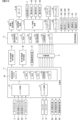
パチンコ遊技機1には、例えば図2に示すような主基板11、演出制御基板12、音声制御基板13、ランプ制御基板14、中継基板15などが搭載されている。その他にも、パチンコ遊技機1の背面には、例えば払出制御基板、情報端子基板、発射制御基板、電源基板などといった、各種の基板が配置されている。
(Substrate configuration)
The
主基板11は、メイン側の制御基板であり、パチンコ遊技機1における上記遊技の進行(特図ゲームの実行(保留の管理を含む)、普図ゲームの実行(保留の管理を含む)、大当り遊技状態、小当り遊技状態、遊技状態など)を制御する機能を有する。主基板11は、遊技制御用マイクロコンピュータ100、スイッチ回路110、ソレノイド回路111などを有する。
The
主基板11に搭載された遊技制御用マイクロコンピュータ100は、例えば1チップのマイクロコンピュータであり、ROM(Read Only Memory)101と、RAM(Random Access Memory)102と、CPU(Central Processing Unit)103と、乱数回路104と、I/O(Input/Output port)105とを備える。
The
CPU103は、ROM101に記憶されたプログラムを実行することにより、遊技の進行を制御する処理(主基板11の機能を実現する処理)を行う。このとき、ROM101が記憶する各種データ(後述の変動パターン、後述の演出制御コマンド、後述の各種決定を行う際に参照される各種テーブルなどのデータ)が用いられ、RAM102がメインメモリとして使用される。RAM102は、その一部または全部がパチンコ遊技機1に対する電力供給が停止しても、所定期間記憶内容が保存されるバックアップRAMとなっている。尚、ROM101に記憶されたプログラムの全部又は一部をRAM102に展開して、RAM102上で実行するようにしてもよい。
The
また、CPU103は、第1始動入賞や第2始動入賞があったか否かを判定し、入賞があった場合には、特図表示結果判定用、大当り種別判定用、変動パターン判定用などの乱数値をそれぞれ抽出して、第1特図保留記憶部や第2特図保留記憶部における空きエントリの最上位に格納(記憶)する始動入賞処理を実行する。
In addition, the
また、CPU103は、第1特図保留記憶部や第2特図保留記憶部に記憶されている保留データの有無などに基づいて特図ゲームを開始するか否かの判定や、特図表示結果判定用の乱数値を示す数値データに基づき、特別図柄や演出図柄の変動表示結果を「大当り」とするか否かを、その変動表示結果が導出表示される前に決定(事前決定)する特別図柄通常処理を実行する。つまり、CPU103は、特図ゲームの変動表示を開始するときに、始動入賞が発生したときに記憶した乱数値に基づいて、当該変動表示の表示結果として大当り表示結果を導出表示するか否かを決定(抽選)する処理を実行する。
Further, the
乱数回路104は、遊技の進行を制御するときに使用される各種の乱数値(遊技用乱数)を示す数値データを更新可能にカウントする。遊技用乱数は、CPU103が所定のコンピュータプログラムを実行することで更新されるもの(ソフトウェアで更新されるもの)であってもよい。
The
I/O105は、例えば各種信号(後述の検出信号)が入力される入力ポートと、各種信号(第1特別図柄表示装置4A、第2特別図柄表示装置4B、普通図柄表示器20、第1保留表示器25A、第2保留表示器25B、普図保留表示器25Cなどを制御(駆動)する信号、ソレノイド駆動信号)を伝送するための出力ポートとを含んで構成される。
The I/
スイッチ回路110は、遊技球検出用の各種スイッチ(ゲートスイッチ21、始動口スイッチ(第1始動口スイッチ22Aおよび第2始動口スイッチ22B)、カウントスイッチ23)からの検出信号(遊技球が通過又は進入してスイッチがオンになったことを示す検出信号など)を取り込んで遊技制御用マイクロコンピュータ100に伝送する。検出信号の伝送により、遊技球の通過又は進入が検出されたことになる。
The
ソレノイド回路111は、遊技制御用マイクロコンピュータ100からのソレノイド駆動信号(例えば、ソレノイド81やソレノイド82をオンする信号など)を、普通電動役物用のソレノイド81や大入賞口扉用のソレノイド82に伝送する。
主基板11(遊技制御用マイクロコンピュータ100)は、遊技の進行の制御の一部として、遊技の進行に応じて演出制御コマンド(遊技の進行状況等を指定(通知)するコマンド)を演出制御基板12に供給する。主基板11から出力された演出制御コマンドは、中継基板15により中継され、演出制御基板12に供給される。当該演出制御コマンドには、例えば主基板11における各種の決定結果(例えば、特図ゲームの表示結果(大当り種別を含む。)、特図ゲームを実行する際に使用される変動パターン(詳しくは後述))、遊技の状況(例えば、可変表示の開始や終了、大入賞口の開放状況、入賞の発生、保留記憶数、遊技状態)、エラーの発生等を指定するコマンド等が含まれる。
The main board 11 (game control microcomputer 100), as part of the control of the progress of the game, produces a production control command (a command to specify (notify) the progress of the game, etc.) according to the progress of the game. 12. The effect control command output from the
演出制御基板12は、主基板11とは独立したサブ側の制御基板であり、演出制御コマンドを受信し、受信した演出制御コマンドに基づいて演出(遊技の進行に応じた種々の演出であり、第1演出装置300、第2演出装置400、第3演出装置500、第4演出装置600、第5演出装置700L,700Rの各可動体の駆動、エラー報知、電断復旧の報知等の各種報知を含む)を実行する機能を有する。
The
演出制御基板12には、演出制御用CPU120と、ROM121と、RAM122と、表示制御部123と、乱数回路124と、I/O125とが搭載されている。
The
演出制御用CPU120は、ROM121に記憶されたプログラムを実行することにより、表示制御部123とともに演出を実行するための処理(演出制御基板12の上記機能を実現するための処理であり、実行する演出の決定等を含む)を行う。このとき、ROM121が記憶する各種データ(各種テーブルなどのデータ)が用いられ、RAM122がメインメモリとして使用される。
The
演出制御用CPU120は、コントローラセンサユニット35Aやプッシュセンサ35Bからの検出信号(遊技者による操作を検出したときに出力される信号であり、操作内容を適宜示す信号)に基づいて演出の実行を表示制御部123に指示することもある。
The
表示制御部123は、VDP(Video Display Processor)、CGROM(Character Generator ROM)、VRAM(Video RAM)などを備え、演出制御用CPU120からの演出の実行指示に基づき、演出を実行する。
The
表示制御部123は、演出制御用CPU120からの演出の実行指示に基づき、実行する演出に応じた映像信号を画像表示装置5に供給することで、演出画像を画像表示装置5に表示させる。表示制御部123は、さらに、演出画像の表示に同期した音声出力や、遊技効果ランプ9の点灯/消灯を行うため、音指定信号(出力する音声を指定する信号)を音声制御基板13に供給したり、ランプ信号(ランプの点灯/消灯態様を指定する信号)をランプ制御基板14に供給したりする。また、表示制御部123は、第1演出装置300、第2演出装置400、第3演出装置500、第4演出装置600、第5演出装置700L,700Rに内蔵された発光手段としての各種LEDを発光させる信号を供給したり、第1演出装置300、第2演出装置400、第3演出装置500、第4演出装置600、第5演出装置700L,700Rの各可動体を動作させる信号を駆動回路に供給する。
The
音声制御基板13は、スピーカ8L、8Rを駆動する各種回路を搭載しており、当該音指定信号に基づきスピーカ8L、8Rを駆動し、当該音指定信号が指定する音声をスピーカ8L、8Rから出力させる。
The
ランプ制御基板14は、遊技効果ランプ9を駆動する各種回路を搭載しており、当該ランプ信号に基づき遊技効果ランプ9を駆動し、当該ランプ信号が指定する態様で遊技効果ランプ9を点灯/消灯する。このようにして、表示制御部123は、音声出力、ランプの点灯/消灯を制御する。
The
尚、音声出力、ランプの点灯/消灯の制御(音指定信号やランプ信号の供給等)、第1演出装置300、第2演出装置400、第3演出装置500、第4演出装置600、第5演出装置700L,700Rの可動体の制御(第1演出装置300、第2演出装置400、第3演出装置500、第4演出装置600、第5演出装置700L,700Rの各可動体を動作させる信号の供給等)は、演出制御用CPU120が実行するようにしてもよい。
Sound output, lamp lighting/extinguishing control (supply of sound designation signal, lamp signal, etc.),
乱数回路124は、各種演出を実行するために使用される各種の乱数値(演出用乱数)を示す数値データを更新可能にカウントする。演出用乱数は、演出制御用CPU120が所定のコンピュータプログラムを実行することで更新されるもの(ソフトウェアで更新されるもの)であってもよい。
The
演出制御基板12に搭載されたI/O125は、例えば主基板11などから伝送された演出制御コマンドを取り込むための入力ポートと、各種信号(映像信号、音指定信号、ランプ信号)を伝送するための出力ポートとを含んで構成される。
I /
演出制御基板12、音声制御基板13、ランプ制御基板14といった、主基板11以外の基板をサブ基板ともいう。パチンコ遊技機1のようにサブ基板が機能別に複数設けられていてもよいし、1のサブ基板が複数の機能を有するように構成してもよい。
Boards other than the
(遊技の進行や演出の進行など)
パチンコ遊技機1が備える打球操作ハンドルへの遊技者による回転操作により、遊技媒体(遊技球)が遊技領域10に向けて発射される。
(Game progress, performance progress, etc.)
A game medium (game ball) is shot toward a
(主基板11で制御される遊技の進行)
遊技領域10を流下した遊技球が通過ゲート41を通過したときには、普図ゲーム(普通図柄の可変表示)が開始される。尚、すでに他の普図ゲームが実行されている、下記の開放制御中など、普図ゲームを開始できないとき(開始条件が成立していないとき)には、4つなどを上限として普図ゲームの実行は保留される。保留された普図ゲームは、当該普図ゲームを開始できる開始条件の成立(他の普図ゲームが実行されておらず、開放制御中でもないなど)により実行される。普図保留記憶数が上限値に達しているときに遊技球が通過ゲート41を通過したときには、当該普図保留記憶数は増えないで、当該通過は無効化される。
(Progress of game controlled by main board 11)
When the game ball flowing down the
普図ゲームで停止表示される可変表示結果には、普図当り図柄(例えば、「7」などの普図)と、普図ハズレ図柄(例えば、「-」などの普図)と、がある。普図当り図柄が停止表示(導出)されるときは、可変表示結果が「普図当り」のときである。普図ハズレ図柄が停止表示(導出)されるときは、可変表示結果が「普図ハズレ」のときである。 The variable display results that are stopped and displayed in the general game include a general game winning pattern (for example, a general pattern such as "7") and a general pattern losing pattern (for example, a general pattern such as "-"). . When the per-universal pattern is displayed (derived) at a stop, the variable display result is "per normal per pattern". When the normal map losing pattern is stopped and displayed (derived), it is when the variable display result is "general map losing".
「普図当り」のときには、普通可変入賞球装置6Bの可動翼片を所定期間傾動位置とする開放制御(第2始動入賞口が開放状態になる。)が行われる。「普図ハズレ」のときには、前記開放制御は行われない。
At the time of "normal hit", opening control (the second start winning opening is opened) is performed to set the movable wing of the normal variable winning
遊技領域10を流下した遊技球が、普通入賞球装置6Aに形成された第1始動入賞口に進入したときには、第1特図ゲームが開始される。また、遊技球が、普通可変入賞球装置6Bに形成された第2始動入賞口に進入したときには、第2特図ゲームが開始される。尚、すでに他の特図ゲームが実行中である、後述の大当り遊技状態に制御されているときなど、特図ゲームを開始できないとき(開始条件が成立していないとき)には、それぞれ4つなどを上限として特図ゲームの実行は保留される。保留された特図ゲームは、特図ゲームを開始できる開始条件の成立(他の特図ゲームが実行されておらず、大当り遊技状態中でもないなど)により実行される。
When the game ball flowing down the
第1特図保留記憶数が上限値に達しているときに遊技球が第1始動入賞口を進入したときには、当該第1特図保留記憶数は増えないで、当該進入は無効化される(賞球はあってもよい)。第2特図保留記憶数が上限値に達しているときに遊技球が第2始動入賞口を進入したときには、当該第2特図保留記憶数は増えないで、当該進入は無効化される(賞球はあってもよい)。 When the game ball enters the first start winning opening when the number of the first special figure reserved memory reaches the upper limit, the entry is invalidated without increasing the number of the first special figure reserved memory ( There may be prize balls). When the game ball enters the second start winning opening when the second special figure reserved memory number reaches the upper limit, the entry is invalidated without increasing the second special figure reserved memory number ( There may be prize balls).
第1特図保留記憶数を増やす遊技球の第1始動入賞口への進入(入賞)を第1始動入賞ともいう。第2特図保留記憶数を増やす遊技球の第2始動入賞口への進入(入賞)を第2始動入賞ともいう。これら入賞を総称して単に始動入賞ともいう。 The entry (winning) of the game ball to the first start winning opening that increases the number of first special figure reservation memories is also called the first starting winning. The entry (winning) of the game ball to the second starting winning opening that increases the number of second special figure reservation memories is also called the second starting winning. These winnings are collectively referred to simply as starting winnings.
特図ゲームで停止表示される可変表示結果には、大当り図柄(例えば、「3」、「7」などの特図)と、ハズレ図柄(例えば、「-」などの特図)と、がある。大当り図柄が停止表示(導出)されるときは、可変表示結果が「大当り」のときである。ハズレ図柄が停止表示(導出)されるときは、可変表示結果が「ハズレ」のときである。 The variable display results to be stopped and displayed in the special game include a big hit pattern (for example, a special pattern such as "3" and "7") and a losing pattern (for example, a special pattern such as "-"). . When the jackpot symbols are stopped and displayed (derived), the variable display result is "big hit". When the lost pattern is stopped and displayed (derived), it is when the variable display result is "losing".
第1特図ゲーム又は第2特図ゲームの可変表示結果が「大当り」(特定表示結果)のときには、遊技者にとって有利な有利状態としての大当り遊技状態に制御される。可変表示結果が「ハズレ」のときには、大当り遊技状態には制御されない。 When the variable display result of the first special game or the second special game is "big win" (specific display result), the game is controlled to a big win game state as an advantageous state for the player. When the variable display result is "losing", the game is not controlled to the jackpot game state.
大当り遊技状態では、特別可変入賞球装置7により形成される大入賞口が開放状態となる。当該開放状態は、所定期間(例えば29秒間)の経過タイミングと、大入賞口に進入した遊技球の数が所定個数(例えば9個)に達するまでのタイミングと、のうちのいずれか早いタイミングまで継続される。このような開放状態をラウンド遊技(単に「ラウンド」ともいう)という。大当り遊技状態では、当該ラウンド遊技が、所定の上限回数(例えば「15回」)に達するまで繰返し実行される(ラウンド遊技以外の期間では、大入賞口が閉鎖する。)。 In the jackpot game state, the jackpot formed by the special variable winning ball device 7 is in an open state. The open state is until the timing when a predetermined period of time (for example, 29 seconds) elapses, or the timing until the number of game balls entering the big winning opening reaches a predetermined number (for example, 9), whichever is earlier. Continued. Such an open state is called a round game (simply referred to as "round"). In the jackpot game state, the round game is repeatedly executed until a predetermined upper limit number of times (for example, "15 times") is reached (during periods other than the round game, the big winning opening is closed).
「大当り」には、「非確変」、「確変」という大当り種別が設定されている。大当り種別が「非確変」のときには、「3」の大当り図柄が停止表示される。大当り種別が「確変」のときには、「7」の大当り図柄が停止表示される。 In the "jackpot", jackpot types such as "non-probability variation" and "probability variation" are set. When the jackpot type is "non-variable probability", the jackpot symbol "3" is stop-displayed. When the jackpot type is "probability variable", the jackpot symbol "7" is stop-displayed.
尚、大当り種別が「確変」のときの「大当り」を「確変大当り」、大当り種別が「非確変」のときの「大当り」を「非確変大当り」ということがある。また、「確変大当り」に基づく大当り遊技状態を「確変大当り遊技状態」ということがある。また、「非確変大当り」に基づく大当り遊技状態を「非確変大当り遊技状態」ということがある。 A ``big hit'' when the jackpot type is ``variable probability'' is sometimes referred to as a ``variable probability big hit'', and a ``jackpot'' when the type of jackpot is ``non-variable probability'' is sometimes referred to as a ``non-variable probability jackpot''. Moreover, the big hit game state based on the "variable probability big win" may be called "variable probability big win game state". In addition, the big hit game state based on the "non-probability variation big hit" may be referred to as "non-probability variation big hit game state".
確変大当り遊技状態が終了した後には、可変表示結果が「大当り」となる確率(大当り確率)が通常状態よりも高くなる確変状態に制御される。確変状態は、次回の大当り遊技状態が開始されるまで継続する。 After the variable probability big win game state is finished, the variable display result is controlled to a variable probability state in which the probability that the variable display result is "big win" (big win probability) is higher than that in the normal state. The variable probability state continues until the next big hit game state is started.
確変大当り遊技状態又は非確変大当り遊技状態が終了した後には、平均的な可変表示時間(可変表示の期間)が通常状態よりも短くなる時短状態に制御される。時短状態は、所定回数(この実施の形態では、100回)の特図ゲームが実行されたことと、次回の大当り遊技状態が開始されたことのうち、いずれか一方の終了条件が先に成立するまで、継続する。 After the probability variable big win game state or the non-probability variable big win game state is finished, the average variable display time (variable display period) is controlled to a short time state shorter than the normal state. In the time-saving state, either one of the execution of the special figure game for a predetermined number of times (100 times in this embodiment) and the start of the next jackpot game state is satisfied first. Continue until you do.
尚、時短状態では、通常状態などの時短状態になっていない非時短状態よりも第2始動入賞口に遊技球が進入しやすい有利変化態様で、普通可変入賞球装置6Bを開放状態と閉鎖状態とに変化させてもよい。例えば、普図ゲームにおける普通図柄の変動時間(普図の可変表示の期間であり、普図変動時間ともいう。)を通常状態のときよりも短くする制御や、各回の普図ゲームで可変表示結果が「普図当り」となる確率を通常状態のときよりも向上させる制御などにより、普通可変入賞球装置6Bを有利変化態様で開放状態と閉鎖状態とに変化させればよい。このような制御は、高開放制御(「時短制御」あるいは「高ベース制御」ともいう)と称される。こうした時短状態に制御されることにより、次に可変表示結果が「大当り」となるまでの所要時間が短縮され、遊技状態は、通常状態よりも遊技者にとって有利な状態となる。
In addition, in the time-saving state, the normal variable winning
尚、通常状態とは、大当り遊技状態等の有利状態や、時短状態や、確変状態等の遊技者にとって有利な状態以外の遊技状態のことであり、普図ゲームにおける可変表示結果が「普図当り」となる確率及び特図ゲームにおける可変表示結果が「大当り」となる確率などのパチンコ遊技機1が、パチンコ遊技機1の初期設定状態(例えばシステムリセットが行われた場合のように、電源投入後に所定の復帰処理を実行しなかったとき)と同一に制御される状態である。
In addition, the normal state is a game state other than an advantageous state such as a jackpot game state, a time saving state, a probability variable state, etc., other than an advantageous state for the player. The
時短状態は、「高ベース」などともいわれ、時短状態でない遊技状態は、「低ベース」「非時短状態」などともいわれる。確変状態は、「高確」などともいわれ、確変状態でない遊技状態は、「低確」、「非確変」などともいわれる。 The time saving state is also referred to as "high base", and the game state that is not the time saving state is also referred to as "low base", "non-time saving state", and the like. The variable probability state is also called "high probability", and the game state that is not the variable probability state is also called "low probability", "non-probability change", and the like.
(演出制御基板12で制御される遊技の進行)
画像表示装置5に設けられた「左」、「中」、「右」の飾り図柄表示エリア5L、5C、5Rでは、第1特図ゲーム又は第2特図ゲームが開始されることに対応して、飾り図柄の可変表示(これも演出の一種である。)が開始される。第1特図ゲームや第2特図ゲームにおいて可変表示結果(確定特別図柄ともいう。)が停止表示されるタイミングでは、飾り図柄の可変表示の表示結果(可変表示結果)となる確定飾り図柄(3つの飾り図柄の組合せ)も停止表示(導出表示)される。
(Progress of the game controlled by the effect control board 12)
The "left", "middle", and "right" decorative
飾り図柄の可変表示が開始されてから終了するまでの期間では、飾り図柄の可変表示態様が所定のリーチ態様となる(リーチが成立する)ことがある。ここで、リーチ態様とは、画像表示装置5の画面上にて停止表示された飾り図柄が後述の大当り組合せの一部を構成しているときに未だ停止表示されていない飾り図柄(「リーチ変動図柄」ともいう)については変動が継続している表示態様などのことである。
During the period from the start of the variable display of the decorative design until the end, the variable display mode of the decorative design may be a predetermined ready-to-win mode (ready-to-win is established). Here, the ready-to-win state refers to a decorative pattern that is not yet stopped when the decorative patterns stopped and displayed on the screen of the
また、この実施の形態では、可変表示中に上記リーチ態様となったことに対応してリーチ演出が実行される。リーチ演出として、演出態様がそれぞれ異なるノーマルリーチ、スーパーリーチA、スーパーリーチBが用意されている。この実施の形態では、大当り期待度は、スーパーリーチB>スーパーリーチA>ノーマルリーチの順で高い。 Further, in this embodiment, a ready-to-win effect is executed in response to the above-described ready-to-win state during variable display. As ready-to-win effects, normal ready-to-win, super ready-to-win A, and super ready-to-win B with different effects are prepared. In this embodiment, the degree of expectation for a big hit is higher in the order of super reach B>super reach A>normal reach.
大当り期待度は、例えば、特図ゲームの可変表示結果が「大当り」となる割合であり、ここでは、飾り図柄の可変表示の表示結果が「大当り」となる割合でもある。 The degree of expectation for a big hit is, for example, the rate at which the variable display result of the special game is a "big hit", and here, it is also the rate at which the display result of the variable display of the decorative symbols is a "big hit".
特図ゲームの可変表示結果が「大当り」となるときには、画像表示装置5の画面上において、飾り図柄の可変表示の表示結果として、予め定められた大当り組合せとなる確定飾り図柄が導出表示される(飾り図柄の可変表示の表示結果が「大当り」となる)。一例として、「左」、「中」、「右」の飾り図柄表示エリア5L、5C、5Rにおける所定の有効ライン上に同一の飾り図柄(例えば、確変大当りのときに「7」、非確変大当りのときに「6」など)が揃って停止表示される。
When the variable display result of the special figure game is "big hit", the determined decoration pattern that becomes a predetermined big hit combination is derived and displayed on the screen of the
可変表示結果が「ハズレ」となる場合には、飾り図柄の可変表示態様がリーチ態様とならずに、飾り図柄の可変表示の表示結果として、非リーチ組合せの確定飾り図柄が停止表示されることがある。また、可変表示結果が「ハズレ」となる場合には、飾り図柄の可変表示態様がリーチ態様となった後に、飾り図柄の可変表示の表示結果として、大当り組合せでない所定のリーチ組合せ(「リーチハズレ組合せ」ともいう)の確定飾り図柄が停止表示されることもある。 When the variable display result is "losing", the variable display mode of the decorative patterns does not become the ready-to-win mode, and the fixed decorative patterns of the non-ready-to-win combination are displayed in a stopped state as the display result of the variable display of the decorative patterns. There is Further, when the variable display result is "losing", after the variable display mode of the decorative pattern becomes the ready-to-win mode, the display result of the variable display of the decorative pattern is a predetermined ready-to-win combination ("reach-losing combination") that is not a big hit combination. ”) may be stopped and displayed.
演出制御用CPU120は、遊技制御用マイクロコンピュータ100から送信された演出制御コマンド(制御情報)に基づいて、飾り図柄の変動表示制御や予告演出といった遊技に関連する各種演出を実行可能とされている。
The
尚、演出制御用CPU120が飾り図柄の可変表示中において実行する予告演出としては、例えば、大当りの可能性を示唆する大当り予告演出や、リーチになるか否かを示唆するリーチ予告、停止図柄を予告する停止図柄予告、遊技状態が確率変動状態であるか否か(潜伏しているか否か)を予告する潜伏予告といったように、可変表示開始時やリーチ成立時において実行される複数の予告を含む。
Note that the
また、本実施の形態では、上記予告を含む各種演出として、第1演出装置300、第2演出装置400、第3演出装置500、第4演出装置600、第5演出装置700L,700Rの各可動体による可動体演出やスピーカ8L,8R、及び遊技効果ランプ9による複合演出を実行可能とされている。尚、これら各種演出は、例えば、可変表示中における所定タイミングや、遊技者がスティックコントローラ31Aまたはプッシュボタン31Bを操作したタイミングで実行される。
In addition, in the present embodiment, the
(演出ユニット200)
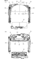
次に、演出ユニット200について、図3~図5に基づいて説明する。図3は、(A)は演出ユニットの各可動体が原点位置に位置した状態を示す正面図、(B)は一部の可動体が演出位置に移動した状態を示す正面図である。図4は、(A)、(B)は演出ユニットの一部の可動体が演出位置に移動した状態を示す正面図である。図5は、演出ユニットの構成を斜め前から見た状態を示す分解斜視図である。尚、以下の説明においては、遊技者が位置する方向をパチンコ遊技機1の前方とし、その反対の方向を後方とする。また、パチンコ遊技機1の前方に位置する遊技者からみて上下左右の方向を基準として説明する。
(Production unit 200)
Next, the
図3~図5に示すように、演出ユニット200は、第1演出装置300と、第1演出装置300の下方に設けられる第2演出装置400と、第1演出装置300の前面側に設けられる第3演出装置500と、第2演出装置400の前面側に設けられる第4演出装置600と、第1演出装置300の背面側に設けられる第5演出装置700L,700Rと、を有し、これら第1演出装置300、第2演出装置400、第3演出装置500、第4演出装置600及び第5演出装置700L,700Rが一体的に組付けられることで構成されている。
As shown in FIGS. 3 to 5, the
図3及び図4に示すように、演出ユニット200は、第1演出装置300、第2演出装置400、第3演出装置500、第4演出装置600及び第5演出装置700L,700Rが組付けられた状態において四角枠状をなすように構成されており、演出ユニット200の開口に画像表示装置5の表示領域が臨むように遊技盤2と画像表示装置5との間に配設されている。遊技盤2と画像表示装置5との間に配設された状態において、各演出装置の可動体が遊技盤2及び遊技盤2に形成された開口2cを透して遊技者から視認可能とされている(図1参照)。
As shown in FIGS. 3 and 4, the
第1演出装置300、第2演出装置400、第3演出装置500、第4演出装置600及び第5演出装置700L,700Rは、それぞれ後述する可動体を有している。各可動体は、図3(A)に示す原点位置と、図3(B)、図4(A)(B)に示す演出位置との間で移動可能に設けられ、原点位置に位置しているとき及び演出位置に位置しているときも少なくとも一部が画像表示装置5の表示領域の前面側に重複するように設けられているが、演出位置に位置しているときは、原点位置に位置しているときよりも画像表示装置5の表示領域との重複領域が大きくなる。
The
また、第1演出装置300、第2演出装置400、第3演出装置500、第4演出装置600及び第5演出装置700L,700Rはそれぞれ独立して動作可能とされていることで、例えば、図3(B)に示すように、第1演出装置300と第2演出装置400の可動体を演出位置まで移動したり、図4(A)に示すように、第3演出装置500の可動体のみを演出位置まで移動したり、図4(B)に示すように、第1演出装置300、第2演出装置400及び第3演出装置500の可動体を演出位置まで移動することができる。尚、第3演出装置500と第4演出装置600については、それぞれの可動体の移動領域の一部が重複していることで(図27参照)、一方が演出位置まで移動したときには他方を演出位置まで移動すると衝突するため、双方を演出位置まで移動する制御は行わない。
In addition, the
(第1演出装置300)
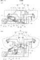
次に、第1演出装置300の詳細について、図6~図11に基づいて説明する。図6は、(A)第1演出装置及び第2演出装置を示す正面図、(B)は第1演出装置及び第2演出装置を示す背面図である。図7は、第1演出装置の構成を斜め前から見た状態を示す分解斜視図である。図8は、第1演出装置の構成を斜め後ろから見た状態を示す分解斜視図である。図9は、(A)はベース体の上辺部を示す斜視図、(B)は第1可動体の要部を斜め後ろから見た状態を示す斜視図である。図10は、図6(A)のA-A断面図である。
図11は、(A)は図6(A)のB-B断面図、(B)は図6(A)のC-C断面図である。図12は、(A)は第1可動体が第1原点位置にある状態を示す概略正面図、(B)は第1可動体が第1演出位置にある状態を示す概略正面図である。図13は、(A)は第1可動体の第1状態を示す概略正面図、(B)は第1可動体の第2状態を示す概略正面図である。図14は、(A)はベース体と第1可動体の要部を示す概略縦断面図、(B)は被案内部の内部構造を示す断面図、(C)は駆動体の内部構造を示す断面図である。図15は、(A)~(C)は第1可動体が第1原点位置に移動して係止される様子を示す概略断面図である。
(First rendering device 300)
Next, the details of the
11, (A) is a cross-sectional view taken along the line BB of FIG. 6(A), and (B) is a cross-sectional view taken along the line CC of FIG. 6(A). 12, (A) is a schematic front view showing a state in which the first movable body is at the first origin position, and (B) is a schematic front view showing a state in which the first movable body is at the first rendering position. 13, (A) is a schematic front view showing the first state of the first movable body, and (B) is a schematic front view showing the second state of the first movable body. 14, (A) is a schematic vertical cross-sectional view showing the main parts of the base body and the first movable body, (B) is a cross-sectional view showing the internal structure of the guided part, and (C) is the internal structure of the driving body. It is a sectional view showing. 15A to 15C are schematic cross-sectional views showing how the first movable body is moved to the first origin position and locked.
図6~図8に示すように、第1演出装置300は、ベース体301と、ベース体301に対し第1原点位置と該第1原点位置よりも下方の第1演出位置との間で上下方向に移動可能に設けられた第1可動体302と、第1可動体302を下方位置から上方位置に移動させる移動手段303L,303Rと、第1可動体302を第1原点位置に保持するための保持手段としての演出用ソレノイド304L,304Rと、第1可動体302の後述する可動部332L,332Rを駆動するための駆動手段305と、を有している。
As shown in FIGS. 6 to 8, the
ベース体301は、上辺部301Hと、該上辺部301Hの左右端から下方に延設される側辺部301L,301Rとにより下向きコ字形に形成され、上辺部301Hの背面側には演出用ソレノイド304L,304Rが設けられている。演出用ソレノイド304L,304Rは、図9(A)及び図10に示すように、本体部304Aと、本体部304Aに対し移動可能なプランジャ304Bと、プランジャ304Bを前方に付勢する圧縮バネ304Cと、プランジャ304Bの先端に固着された係止部材304Dと、を有する。
The
演出用ソレノイド304L,304Rがオフ状態であるときには、係止部材304Dが圧縮バネ304Cの付勢力により前方に突出する進出位置に位置し(図9(A)参照)、上辺部301Hに形成された貫通孔310L,310Rを通して係止部材304Dの先端が上辺部301Hの前面側に突出する。演出用ソレノイド304L,304Rがオン状態になると、係止部材304Dが圧縮バネ304Cの付勢力に抗して後側に退避する退避位置に位置することで、係止部材304Dの先端が上辺部301Hの背面側に退避する。
When the
このように、演出用ソレノイド304L,304Rがオフ状態となり係止部材304Dの先端が上辺部301Hの前面側に突出すると、係止部材304Dが第1可動体302の後述する被係止部335L,335Rを係止する係止状態となり(図10参照)、第1可動体302を第1原点位置に保持可能となる。また、演出用ソレノイド304L,304Rがオン状態となり係止部材304Dの先端が上辺部301Hの背面側に退避すると、係止部材304Dと被係止部335L,335Rとの係止状態が解除され、第1可動体302が第1原点位置から第1演出位置に向けて自重により落下する。
In this way, when the
また、図10に示すように、演出用ソレノイド304L,304Rは、水平面に対し前側に向けて下方に傾斜する傾斜状態で設けられていることで、演出用ソレノイド304L,304Rがオフ状態であるときに、演出用ソレノイド304L,304Rが水平に設けられた場合に比べて、係止部材304Dが圧縮バネ304Cの付勢力に抗して後上方に押し込まれにくくなるようにしている。また、係止部材304Dが被係止部335L,335Rを係止している第1可動体302の保持状態において演出用ソレノイド304L,304Rをオン状態として係止状態を解除するときに、第1可動体302の荷重が加わっている係止部材304Dをスムーズに後側に退避させることができる。尚、水平面に対する傾斜角度θは約5度とされているが、傾斜角度θは上記5度に限定されるものではなく、任意に変更可能である。
In addition, as shown in FIG. 10, the
また、係止部材304Dにおいて被係止部335L,335Rが接触する箇所に、摩擦力軽減部として例えばローラ(図示略)を設けたり、ローラに替えて微小球体を設けたり、フッ素加工などにより低摩擦面を形成してもよい。このようにすることで、係止部材304Dに第1可動体302の荷重が加わっている状態でも、係止部材304Dをスムーズに後側に退避させることができる。
In addition, at the place where the locked
図9(A)及び図11(A)に示すように、上辺部301Hの前面側における貫通孔310L,310Rの左右側上方位置には、第1可動体302を上方に向けて上辺部301H側に向けて誘導するガイド壁315L,315Rが形成されている。ガイド壁315L,315Rは、上辺部301Hに対し前方に離れた位置において、上方から下方に向けて前側に傾斜するように延設されている。また、上辺部301Hの下辺部には、第1可動体302を上方に向けて前側に向けて誘導するガイド壁312が形成されている。
As shown in FIGS. 9(A) and 11(A), above the left and right sides of the through-
また、図6~図9(A)及び図13(A)に示すように、上辺部301Hの前面左右側には、前方に突出する突出部311L,311Rが形成されている。突出部311L,311Rの下面は、第1可動体302が第1原点位置に保持された状態において第1可動体302の上縁に近接する湾曲壁部311A,311Bが、第1可動体302の上縁に沿うように湾曲状に形成されている。
Further, as shown in FIGS. 6 to 9A and 13A, projecting
図6~図8及び図12に示すように、左右の側辺部301L,301Rの前面には、移動手段303L,303Rが設けられている。移動手段303L,303Rは、図12に示すように、上下方向に延設され上下端部が側辺部301L,301Rに対し回転可能に軸支された円柱状の案内軸316L,316Rと、案内軸316L,316Rを軸心周りに回転させるための移動用モータ318L,318Rと、移動用モータ318L,318Rの動力を案内軸316L,316Rに伝達するギヤ部材317L,317Rと、から主に構成され、移動用モータ318L,318Rが駆動することで案内軸316L,316Rが軸心周りに回転するようになっている。また、案内軸316L,316Rの周面には、凹状の溝部319が螺旋状に形成されている。
As shown in FIGS. 6 to 8 and 12, moving means 303L and 303R are provided on the front surfaces of the left and
案内軸316L,316Rには、第1可動体302の左右端に設けられた被案内部333L,333Rと、該被案内部333L,333Rの下方に配置され第1可動体302を下方の第1演出位置から第1原点位置に向けて移動(上昇)させるための駆動体320L,320Rと、が上下方向に移動可能に設けられている。
The
図14(B)に示すように、被案内部333L,333Rには、案内軸316L,316Rが挿入可能な上下方向に貫通する貫通孔321が形成されている。被案内部333L,333Rが駆動体320L,320Rよりも上方位置になるように、該被案内部333L,333Rの貫通孔321に案内軸316L,316Rが挿入される。この貫通孔321の内径R1は、案内軸316L,316Rの外径R2よりも大きい(内径と外径との寸法差が十分に大きい)ことで(R1>R2)、案内軸316L,316Rの外径R2と貫通孔321の内径R1との間には隙間S1(遊び)が設けられている(R1-R2=S1)。よって、被案内部333L,333Rが案内軸316L,316Rに対してスムーズに上下方向に移動可能であるとともに、被案内部333L,333Rは、案内軸316L,316Rに対して第1可動体302の移動方向に対し交差する方向である前後左右方向に若干移動できるようになっている。言い換えれば、被案内部333L,333Rの貫通孔321の内周面と案内軸316L,316Rの外周面との面接触が抑制され、該摩擦力や溝部319に引っ掛かるなどして被案内部333L,333R(つまり第1可動体302)の上下移動が妨げられないようにしている。
As shown in FIG. 14B, the guided
また、図14(C)に示すように、略直方体をなす駆動体320L,320Rには、上下方向に貫通する貫通孔322が形成されている。該貫通孔322には案内軸316L,316Rが挿入される。この貫通孔322の内径R3は、案内軸316L,316Rの外径R2よりも大きいことで(R3>R2)、案内軸316L,316Rの外径R2と貫通孔322の内径R3との間には隙間S2(遊び)が設けられている(R3-R2=S2)。よって、駆動体320L,320Rが案内軸316L,316Rに対してスムーズに上下方向に移動可能であるとともに、駆動体320L,320Rは、案内軸316L,316Rに対して第1可動体302の移動方向に対し交差する方向である前後左右方向に若干移動できるようになっている。言い換えれば、駆動体320L,320Rの貫通孔322の内周面と案内軸316L,316Rの外周面との面接触が抑制され、該摩擦力や溝部319に引っ掛かるなどして駆動体320L,320Rの上下移動が妨げられないようにしている。
Further, as shown in FIG. 14(C), a through
また、貫通孔322の内径R3は、貫通孔321の内径R1よりも小さいことで(R1>R3)、案内軸316L,316Rの外径R2と貫通孔322の内径R3との間に形成される隙間S2(遊び)は、案内軸316L,316Rの外径R2と貫通孔321の内径R1との間に形成される隙間S1(遊び)よりも小さい(S2<S1)。
In addition, since the inner diameter R3 of the through
貫通孔322の内周面には、溝部319に係合可能な係合部323が突設されている。また、駆動体320L,320Rには、それぞれ図示しない規制片が突設されており、この規制片が側辺部301L,301Rに案内軸316L,316Rと平行に上下方向に向けて延設された凹溝(図示略)に挿入されていることで、案内軸316L,316Rを中心とする回転が規制された状態で上下方向に案内されている。
An engaging
よって、左右の案内軸316L,316Rが回転したときに、駆動体320L,320Rが案内軸316L,316Rを中心として回転することが規制され、また、係合部323が案内軸316L,316Rの溝部319に嵌合されていることで、案内軸316L,316Rが第1方向に回転すると駆動体320L,320Rが上昇し、案内軸316L,316Rが第1方向とは逆の第2方向に回転すると駆動体320L,320Rが下降するようになっている。
Therefore, when the left and
よって、貫通孔321は、第1可動体302を自重により落下させる必要があるため隙間S1が大きくなるように大径とする一方で、貫通孔322は、駆動体320L,320Rの係合部323を溝部319に係合させる必要があるため貫通孔322よりは小径としている。
Therefore, the through
また、左右の側辺部301L,301Rの前面における下部位置には、自重により落下してきた第1可動体302を受止めたときの衝撃を緩衝する緩衝手段としてのシリンダーダンパ324L,324R(ショックアブソーバ)が設けられている。シリンダーダンパ324L,324Rは、筒体324Aと該筒体324Aに伸縮可能に挿入されたピストンロッド324Bとを有し、筒体324A内に設けられたガス(気体)やオイル(流体)などにより、ピストンロッド324Bが伸長位置から収縮位置まで押し下げられる際に衝撃が減衰されるようになっている。また、ピストンロッド324Bは、第1可動体302が上昇して負荷がなくなると、ガスの圧力などにより付勢されて収縮位置から伸長位置まで復帰する。
尚、緩衝手段としてシリンダーダンパ324L,324R(ショックアブソーバ)を設けた形態を例示したが、本発明はこれに限定されるものではなく、シリンダーダンパ324L,324Rに替えてバネやゴム材などを適用してもよいし、このような緩衝手段を設けなくてもよい。
Although the embodiment in which the
図7及び図8に示すように、第1可動体302は、ベース部331と、ベース部331の前面側に動作可能に設けられる可動部332L,332Rと、可動部332L,332Rを駆動するための駆動手段305と、を有している。
As shown in FIGS. 7 and 8, the first
ベース部331は、非透過性の合成樹脂材により正面視略横長長方形状をなす板材にて構成され、左右側には、案内軸316L,316Rに案内される被案内部333L,333Rが形成されている。被案内部333L,333Rには、図14(B)に示すように案内軸316L,316Rが挿入可能な貫通孔321が形成されていることで、第1可動体302は、ベース部331の左右側に設けられた被案内部333L,333Rを介して、左右の案内軸316L,316Rにより上下方向に移動可能に案内される。また、ベース部331の背面には、補強用の金属板313が取付けられている。
The
図7及び図8及び図9(B)に示すように、ベース部331の上辺左右側には、演出用ソレノイド304L,304Rの係止部材304Dの先端部が挿入可能な四角形状の貫通孔334L,334Rが形成されており、この貫通孔334L,334Rの上縁は、係止部材304Dが係止される被係止部335L,335R(図10参照)とされている。
As shown in FIGS. 7, 8, and 9B, rectangular through
ベース部331の上縁における左右方向の中央位置には、可動部332L,332Rを回動可能に案内するための長孔336L,336Rが形成されている。また、ベース部331における長孔336L,336Rの左右側には、複数の長孔337L,337R、338L,338R、339L,339Rが形成されている。これら長孔336L,336R、337L,337R、338L,338R、339L,339Rは、ベース部331の上方に設定される仮想の回動中心を中心とする円弧状に形成されている。尚、金属板313にも各長孔336L,336R、337L,337R、338L,338R、339L,339Rに対応する長孔が形成されている。
可動部332L,332Rは、ベース部材341L,341Rと、ベース部材341L,341Rの前面側に配置される透過性の合成樹脂材からなるレンズ部材342L,342Rと、から主に構成されている。ベース部材341L,341Rとレンズ部材342L,342Rとの間には、前面に複数の演出用LED343が設けられたLED基板344(図10(A)、図11参照)が設けられており、演出用LED343が発光したときに、演出用LED343からの光がレンズ部材342L,342Rを通して前方に拡散して出射されるようになっている。
The
ベース部材341L,341Rそれぞれの背面には、長孔336L,336Rに挿入されるガイド軸346L,346Rと、長孔337L,337Rに挿入される各2個のガイド軸347L,347Rと、長孔339L,339Rに挿入されるガイド軸349L,349Rと、が背面側に向けて突設されており、各長孔336L,336R、337L,337R、339L,339R内を摺動可能とされている。また、ベース部材341L,341Rそれぞれの対向辺には、後述する回動用モータ350を内部に挿入可能とするための切欠部348L,348Rが形成されている。
On the rear surface of each of the
また、ベース部材341L,341Rの背面上部には、ガイド部材345L,345Rが設けられている。ガイド部材345L,345Rは、図9(B)及び図11(A)に示すように、ベース体301のガイド壁315L,315Rと略平行をなすように、上方に向けて後側に離れるように傾斜して設けられ、ベース部331の上方における被係止部335L,335Rの近傍位置にて、上部がベース部331よりも後側に位置するように配置される。尚、図14(A)に示すように、ガイド部材345L,345Rは、ガイド壁315L,315Rと略平行をなす傾斜壁部345Aと該傾斜壁部345Aの左右側辺に立設される側壁部345Bとからコ字形をなし、左右の側壁部345Bの前端縁がガイド壁315L,315Rに摺接可能となっている。
Further, guide
駆動手段305は、ベース部331における左右方向の中央位置に配置され、本体部が前方に突出するとともに駆動軸が背面側に突出するように設けられる回動用モータ350と、回動用モータ350の駆動軸350Aに固着されベース部331の背面側に回動可能に設けられる円形の回動盤351と、回動盤351の回動中心を挟んで対向する位置に一端が軸支された円弧状のリンク部材352A,352Bと、長孔337L,337Rの背面側に突出されるガイド軸347L,347Rとリンク部材352A,352Bとに両端が軸支され、ガイド軸347Lとリンク部材352A、ガイド軸347Rとリンク部材352Bを連結するリンク部材353L,353Rと、上端がベース部材341L,341Rに係止されるとともに、下端がベース部331に係止され、長孔338L,338Rに沿うように配置される圧縮バネ354L,354Rと、から主に構成される。
The driving means 305 is arranged in the center position of the
(第1可動体302の動作例)
次に、第1可動体302の動作例について、図12~図15に基づいて説明する。図12は、(A)は第1可動体が第1原点位置にある状態を示す概略正面図、(B)は第1可動体が第1演出位置にある状態を示す概略正面図である。図13は、(A)は第1可動体の第1状態を示す概略正面図、(B)は第1可動体の第2状態を示す概略正面図である。図14は、(A)はベース体と第1可動体の要部を示す概略縦断面図、(B)は被案内部の内部構造を示す断面図、(C)は駆動体の内部構造を示す断面図である。図15は、(A)~(C)は第1可動体が第1原点位置に移動して係止される様子を示す概略断面図である。
(Example of operation of the first movable body 302)
Next, an operation example of the first
図12(A)に示すように、第1可動体302は、第1原点位置においてベース体301の上辺部301Hの前面側にて保持されている。具体的には、図10に示すように、演出用ソレノイド304L,304Rの係止部材304Dの先端部が貫通孔334L,334Rに挿入されて被係止部335L,335Rを係止することにより、第1可動体302が第1原点位置に保持される。このように、左右の係止部材304Dにより第1可動体302を保持しているため、係止部材304Dには第1可動体302の荷重が加わっている。
As shown in FIG. 12A, the first
ここで、演出用ソレノイド304L,304Rをオン状態として係止部材304Dが後方に退避する退避状態となると、第1可動体302が第1原点位置から第1演出位置に向けて自重により落下する。落下した第1可動体302は、第1演出位置に到達する前に被案内部333L,333Rがシリンダーダンパ324L,324Rのピストンロッド324Bに当接し、ピストンロッド324Bが伸長位置から収縮位置まで押し下げられることで衝撃が減衰される。そして、ピストンロッド324Bが収縮位置まで押し下げられたときに第2演出位置に到達する。このように、落下する第1可動体302を受止めて第1演出位置にて移動規制するための移動規制手段としてシリンダーダンパ324L,324Rを用いることにより、落下の衝撃を好適に緩衝できるため、第1可動体302やベース体301の破損や衝撃音の発生等を防止できる。
Here, when the
尚、駆動体320L,320Rは、第1演出位置よりも下方に位置しているため、第1可動体302が第1演出位置まで移動したときに被案内部333L,333Rが駆動体320L,320Rに接触することはないが、被案内部333L,333Rに当接することで第1可動体302の下方への移動が規制されるようにしてもよい。
In addition, since the driving
また、移動用モータ318L,318Rにより案内軸316L,316Rを第1方向に回転させることで、駆動体320L,320Rが上昇するとともに、該駆動体320L,320Rが被案内部333L,333Rに当接して上方に押し上げることにより、第1可動体302が第1演出位置から第1原点位置まで移動する。
Further, by rotating the
図13に示すように、第1可動体302は、第1原点位置以外の位置においてベース部331に対し可動部332L,332Rが可動することにより、図13(A)に示す第1状態から図13(B)に示す第2状態に変形可能とされている。
As shown in FIG. 13, the first
図13(A)に示すように、第1可動体302が第1状態であるときには、ベース部331の前面側に可動部332L,332Rが重複していることで、ベース部331の前面における被案内部333L,333R以外の領域が被覆されているので、ベース部331に設けられた回動用モータ350や長孔336L,336R、337L,337R、338L,338R、339L,339Rなどが遊技者から視認不能となる。
As shown in FIG. 13A, when the first
また、各ガイド軸346L,346R、347L,347R、349L,349Rは、各長孔336L,336R、337L,337R、339L,339Rの下端側に位置しているとともに、圧縮バネ354L,354Rは伸長状態とされている。また、リンク部材352A,352Bは、両端の軸部が回動盤351の回動中心となる駆動軸350Aの両側において該両端の軸部と駆動軸350Aとが水平線上に配置されるように、駆動軸350Aの上下に該駆動軸350Aを迂回するように配置されている。
Further, the
ここで、図13(B)に示すように、回動用モータ350により回動盤351が正面視反時計回りに約180度回動すると、リンク部材352A,352Bと回動盤351との軸部が左右に入れ替わってリンク部材352A,352Bが左右側に移動することで、左側の2個のガイド軸347Lと右側の2個のガイド軸347Rとが長孔337L,337Rに沿って斜め上方に移動するとともに、これに伴い、ガイド軸346L,346R、349L,349Rも長孔336L,336R、339L,339Rに沿って斜め上方に移動する。よって、可動部332L,332Rは、当接辺332A,332Bの上端付近を中心として逆方向に回動することで、各々の外側部が上方に吊り上がるように変形して第1状態から第2状態に変化する。
Here, as shown in FIG. 13B, when the
このように第2状態に変化すると、当接辺332Aと当接辺332Bとは上端を中心として下端部が外側方に離れるため、ベース部331の前面において当接辺332Aと当接辺332Bとの間の正面視略三角形状の領域と回動用モータ350の前面側が開放される。よって、ベース部331の前面の一部と回動用モータ350が遊技者から視認可能となる。
When the contacting
次に、第1可動体302が第1原点位置にて保持される際の動作例について、図14及び図15に基づいて説明する。
Next, an operation example when the first
図14(A)に示すように、第1可動体302が第1原点位置にて保持されている状態では、演出用ソレノイド304L,304Rの係止部材304Dの先端部が貫通孔334L,334Rに後側から挿入されることで、被係止部335L,335Rが係止部材304Dにより係止されている。
As shown in FIG. 14(A), when the first
一方、図14(B)に示すように、案内軸316L,316Rの外径R2と貫通孔321の内径R1との間には隙間S1(遊び)が設けられていることで(R1-R2=S1)、案内軸316L,316Rにより移動が案内されている被案内部333L,333Rを有する第1可動体302は、第1原点位置と第1演出位置との間での上下方向に移動可能なだけではなく、前後左右方向にも移動可能、つまり、遊びによるがたつきが生じる可動体とされている。
On the other hand, as shown in FIG. 14B, a gap S1 (play) is provided between the outer diameter R2 of the
よって、第1可動体302が第1原点位置にて保持されている状態において、例えば、後述する他の演出装置が動作したり、パチンコ遊技機1に外力が加わることなどにより振動が生じることで、第1可動体302にがたつきが生じて前後方向へ移動した場合、被係止部335L,335Rが係止部材304Dの前方に移動して落下してしまうことがある。また、演出用ソレノイド304L,304Rは前傾しているため被係止部335L,335Rが前方へ移動しやすい。そこで、第1可動体302をベース体301に最も近づけたときに係止部材304Dにおいて被係止部335L,335Rが係止されている領域の前後寸法をL1とした場合、前後寸法L1を隙間S1よりも大きくしておけば、振動により第1可動体302が前方向へ隙間S1に相当する長さ移動したとしても、被係止部335L,335Rが係止部材304Dの前方に移動して落下することを防止できる。
Therefore, in a state where the first
また、図14(A)に示すように、第1可動体302が第1原点位置にて保持されている状態において、ベース体301のガイド壁315L,315Rの背面に、第1可動体302のガイド部材345L,345Rにおける側壁部345Bの前端縁が当接しているため、第1可動体302の少なくとも前方への移動が規制されている。よって、振動により被係止部335L,335Rが係止部材304Dの前方に移動して落下することを防止できる。
Further, as shown in FIG. 14A, in a state in which the first
次に、図15(A)に示すように、駆動体320L,320Rの上昇により第1可動体302が第1演出位置から上昇して第1原点位置に近接した後、図15(B)に示すように、ベース体301のガイド壁315L,315Rの背面下部に、第1可動体302のガイド部材345L,345Rにおける側壁部345Bの前端縁上部が当接する。そして、第1可動体302が上昇するにつれて、傾斜するガイド壁315L,315Rによりガイド部材345L,345Rが後上方に向けて誘導されながら当接面積が増加していくため、第1可動体302は、隙間S1分、上昇しながら後側のベース体301に近づいていく。
Next, as shown in FIG. 15(A), the driving
そして、図15(C)に示すように、被係止部335L,335Rが演出用ソレノイド304L,304Rの係止部材304Dよりも上方に移動すると、係止部材304Dが圧縮バネ304Cに付勢力により貫通孔334L,334Rに挿入されて被係止部335L,335Rが係止部材304Dにより係止され、第1可動体302が第1原点位置にて保持される。
Then, as shown in FIG. 15(C), when the locked
このように、係止部材304Dにより被係止部335L,335Rが係止されるまでに、ガイド壁315L,315Rにガイド部材345L,345Rの側壁部345Bが摺接することで第1可動体302がベース体301側に誘導されるので、係止部材304Dにより被係止部335L,335Rを好適に係止することができる。
In this manner, the
また、係止部材304Dにより被係止部335L,335Rが係止され第1可動体302が第1原点位置に保持された状態において、ガイド壁315L,315Rの背面にガイド部材345L,345Rの側壁部345Bが当接していることで、被係止部335L,335Rの前方への移動が規制されていることで、被係止部335L,335Rの係止部材304D先端から落下してしまうことを防止できる。また、ガイド部材345L,345Rはガイド壁315L,315Rの背面に当接しているため、第1可動体302が落下する際にガイド部材345L,345Rがガイド壁315L,315Rに摺接することはないので、落下に影響が及ぶことはない。
Further, in a state where the locked
(第2演出装置400)
次に、第2演出装置400の詳細について、図16~図17に基づいて説明する。図16は、(A)は第2演出装置の構成を斜め前から見た状態を示す分解斜視図、(B)は第2演出装置の構成を斜め後ろから見た状態を示す分解斜視図である。図17は、(A)は第2可動体が第2原点位置にある状態、(B)は第2可動体が第2演出位置にある状態を示す概略正面図である。
(Second production device 400)
Next, the details of the
図16(A)、(B)及び図17に示すように、第2演出装置400は、ベース体401と、ベース体401に対し第2原点位置と該第2原点位置よりも下方の第2演出位置との間で上下方向に移動可能に設けられた第2可動体402と、第2可動体402を下方位置から上方位置に移動させる駆動手段403と、を有している。尚、第2演出装置400は第1演出装置300の下方位置に設けられている(図6参照)。
As shown in FIGS. 16A, 16B, and 17, the
ベース体401には、駆動手段403が設けられている。駆動手段403は、ベース体401の前面左側に設けられた駆動用モータ410と、駆動用モータ410の駆動軸に固着されたピニオンギヤ411と、ピニオンギヤ411に噛合するギヤ部412及びギヤ部412とは別個に形成されたギヤ部413を有するラックギヤ414と、ギヤ部413に噛合するピニオンギヤ415と、ピニオンギヤ415の回動軸に固着された回転板416と、ベース体401の前面に突設された回動軸417を中心として回動可能に設けられた回動アーム418と、から主に構成されている。
A driving means 403 is provided on the
ピニオンギヤ411、ラックギヤ414、ピニオンギヤ415はベース体401の背面側に設けられている。また、回転板416の前面における回動軸の偏心位置には連結軸416Aが突設されており、連結軸416Aは回動アーム418に形成された長孔419内に摺動可能に挿入されている。また、回動アーム418の先端に形成された長孔436には、ベース部421の背面側に突設された連結軸437が挿入されている。
第2可動体402は、ベース部421と、ベース部421の前面側に回動可能に設けられた可動部422L,422Rと、から構成される。ベース部421は、ベース体401に対し上下方向を向くレール部材420を介して上下方向に移動可能に設けられている。また、レール部材420の左側には、上下方向を向く長孔423が形成されている。長孔423の上端部は、左上方に向けて湾曲している。
The second
可動部422L,422Rは、ベース部材425L,425Rと、該ベース部材425L,425Rの前面側に配置されるレンズ部材426L,426Rと、内部に設けられる複数の演出用LED427(図2参照)と、から主に構成され、演出用LED427からの光がレンズ部材426L,426Rを通して拡散して前方に出射されるようになっている。
The
ベース部材425L,425Rの背面下部には回動軸427L,427Rが突設されており、ベース部421に回動可能に軸支されている。また、回動軸427L,427Rには、互いに噛合するギヤ部材428L,428Rが設けられており、回動軸427L,427Rが同期して互いに逆回動するようになっている。尚、右側のギヤ部材428Rの下方にはガイド軸429が突設されており、ガイド軸429は長孔423に挿入されている。また、ベース部材425L,425Rの背面左右側にはガイド軸430L,430Rが突設されており、ベース部421に形成された長孔431L,431Rに摺動可能に挿入されている。また、ベース部421の右側には、ベース部材425Rに下端が係止された圧縮バネ432の上端が係止されている。
Rotating
(第2演出装置400の動作例)
図17(A)に示すように、第2可動体402は、第2原点位置においてベース体401の前面側に位置し、可動部422L,422Rの当接辺435A,435Bが当接して左右に並設される第1状態とされている。第1状態において駆動用モータ410によりピニオンギヤ411が回動すると、ラックギヤ414が右側方にスライド移動してピニオンギヤ415と回転板416が正面視反時計回りに回転することにより、回転板416の連結軸416Aを介して回動アーム418が上方に向けて回動する。
(Operation example of the second effect device 400)
As shown in FIG. 17(A), the second
図17(B)に示すように、回動アーム418が回動することで、回動アーム418に連結軸437を介して連結されたベース部421が上方に移動するため、第2可動体402が第2演出位置まで上昇する。また、ベース部421の上昇に伴いガイド軸429が長孔423の上端側まで移動して湾曲部に差し掛かることで、右側のギヤ部材428Rが回転し、該ギヤ部材428Rの回転に伴ってギヤ部材428Lが回転する。これにより、第2可動体402が第2原点位置から第2演出位置まで移動したときに、可動部422L,422Rは、当接辺422A,422Bの下端付近を中心として逆方向に回動することで、各々の外側部が下方に下がるように変形して第1状態から第2状態に変化する。
As shown in FIG. 17(B), when the
このように、第2可動体402が第2演出位置まで移動したときに、可動部422L,422Rが当接辺422A,422Bの下端付近を中心として逆方向に回動することで、各々の外側部が下方に下がるように変形して第1状態から第2状態に変化するのに対し、前述した第1可動体302が第1演出位置まで移動したときに、可動部332L,332Rが当接辺332A,332Bの上端付近を中心として逆方向に回動することで、各々の外側部が上方に吊り上がるように変形して第1状態から第2状態に変化する(図29(B)参照)。
In this way, when the second
(第3演出装置500)
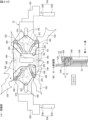
次に、第3演出装置500の詳細について、図18~図26に基づいて説明する。図18は、(A)は第3可動体が第3原点位置に位置している状態を示す正面図、(B)は第3演出位置に位置している状態を示す正面図である。図19は、(A)は第3可動体が第3原点位置に位置している状態を示す背面図、(B)は第3演出位置に位置している状態を示す背面図である。図20は、第3演出装置の構成を斜め前から見た状態を示す分解斜視図である。図21は、第3演出装置の構成を斜め後ろから見た状態を示す分解斜視図である。図22は、第3可動体の要部を示す背面図である。図23は、(A)は第3可動体が第3原点位置に位置している状態を示す概略背面図、(B)は第3演出位置に位置している状態を示す概略背面図である。図24は、(A)は第3可動体がシリンダーダンパに当接した状態を示す背面図、(B)は図24(B)の(A)のF-F断面図である。図25は、(A)は第3可動体が第3演出位置まで移動した状態を示す背面図、(B)は図24のG-G断面図である。図26は、(A)は図23(B)のD-D断面図、(B)は図23(B)のE-E断面図である。尚、図24、図25では説明の便宜上、第2可動部533L,533Rの図示は省略している。
(Third rendering device 500)
Next, the details of the
図18~図21に示すように、第3演出装置500は、ベース体501と、ベース体501に対し第3原点位置と該第3原点位置よりも下方の第3演出位置との間で上下方向に移動可能に設けられた第3可動体502と、第3可動体502を第3原点位置に保持するための保持手段としての演出用ソレノイド504L,504Rと、第3可動体502を第3原点位置と第3演出位置との間での移動を案内する円柱状の案内軸505L,505Rと、を有している。
As shown in FIGS. 18 to 21, the
ベース体501は、上辺部501Hと、該上辺部501Hの左右端から下方に延設される側辺部501L,501Rとにより下向きコ字形に形成され、側辺部501L,501Rの前面上部に演出用ソレノイド504L,504Rが設けられている。演出用ソレノイド504L,504Rは、特に図示しないが、本体部と、該本体部に対し移動可能なプランジャと、該プランジャを前方に付勢する圧縮バネと、プランジャの先端に固着された係止部材504D(図23参照)と、を有する。
The
演出用ソレノイド504L,504Rがオフ状態となり係止部材504Dの先端が上辺部501Hの前面側に突出すると、係止部材504Dが第3可動体502の被案内部535L,535Rを係止する係止状態となり、第3可動体502を第3原点位置に保持可能となる。また、演出用ソレノイド504L,504Rがオン状態となり係止部材504Dの先端が上辺部501Hの背面側に退避すると、係止部材504Dと被案内部535L,535Rとの係止状態が解除され、第3可動体502が第3原点位置から第3演出位置に向けて自重により落下する。
When the
第3可動体502は、ベース部531と、ベース部531の前面側に動作可能に設けられる第1可動部532A~532Dと、ベース部531の背面側に動作可能に設けられる第2可動部533L,533Rと、第3可動体502の動作に応じて第1可動部532A~532Dと第2可動部533L,533Rとを連動させるためのスライド部材534L,534Rと、第1可動部532A~532Dの前面側に設けられる装飾部538と、を有している。また、第1可動部532A~532Dは、ベース部531と装飾部538との間に動作可能に設けられ、装飾部538はベース部531の前面側に固定されている。尚、第1可動部532A~532Dや第2可動部533L,533Rの前面には装飾が施されている。
The third
ベース部531は、正面視略横長長方形状に形成される板材からなり、背面には補強用の金属板537が取付けられている。左右端には、案内軸505L,505Rが挿入可能な上下方向に貫通する貫通孔536が形成された被案内部535L,535Rが設けられている。この貫通孔536の内径R4は、案内軸505L,505Rの外径R5よりも大きい(内径と外径との寸法差が十分に大きい)ことで(R4>R5)、案内軸505L,505Rの外径R5と貫通孔536の内径R4との間には隙間S3(遊び)が設けられている(R4-R5=S3)。よって、被案内部535L,535Rが案内軸505L,505Rに対してスムーズに上下方向に移動可能であるとともに、被案内部535L,535Rは、案内軸505L,505Rに対して第3可動体502の移動方向に対し交差する方向である前後左右方向に若干移動できるようになっている。言い換えれば、被案内部535L,535Rの貫通孔536の内周面と案内軸505L,505Rの外周面との面接触が抑制され、摩擦力によって被案内部535L,535R(つまり第3可動体502)の上下移動が妨げられるようなことがない。尚、隙間S3は、前述した隙間S1よりも小さく、隙間S2とほぼ同一とされていればよい。
The
図21に示すように、ベース部531には、左右方向を向く直線状の長孔546L,546Rが左右側に2個ずつ形成されているとともに、円弧状の長孔547A~547Dが形成されている。長孔547A~547Dは、後述する各回動軸548A~548Dを中印とする円弧形状とされている。尚、金属板537にも各長孔547A~547Dに対応する長孔525が形成されている(図24(B),図25(B)参照)。また、前面における左右方向の中央位置上部には、回動軸548A,548Bが突設され、中央位置下部には、回動軸548C,548Dが突設されている。
As shown in FIG. 21, the
また、左右の側辺部501L,501Rの背面における下部位置には、自重により落下してきた第3可動体502を受止めたときの衝撃を緩衝する緩衝手段としてのシリンダーダンパ524L,524R(ショックアブソーバ)が設けられている。シリンダーダンパ524L,524Rは、筒体524Aと該筒体524Aに伸縮可能に挿入されたピストンロッド524Bとを有し、筒体524A内に設けられたガス(気体)やオイル(流体)などにより、ピストンロッド524Bが伸長位置から収縮位置まで押し下げられる際に衝撃が減衰されるようになっている。また、ピストンロッド524Bは、第3可動体502が上昇して負荷がなくなると、ガスの圧力などにより付勢されて収縮位置から伸長位置まで復帰する。
尚、緩衝手段としてシリンダーダンパ524L,524R(ショックアブソーバ)を設けた形態を例示したが、本発明はこれに限定されるものではなく、シリンダーダンパ524L,524Rに替えてバネやゴム材などを適用してもよいし、このような緩衝手段を設けなくてもよい。
Although the embodiment in which the
第1可動部532A~532Dは、透過性を有する帯板状の合成樹脂材により稲妻を模した形状をなし、それぞれの中央側の一端に形成された軸受部が前後方向を向く回動軸548A~548Dに軸支されている。また、第1可動部532A~532Dの背面における軸受部から離れた位置にはガイド軸549A~549Dが突設されており、ベース部531の長孔547A~547D内に摺動可能に挿入されている。詳しくは、ガイド軸549Aは長孔547Aに挿入され、ガイド軸549Bは長孔547Bに挿入され、ガイド軸549Cは長孔547Cに挿入され、ガイド軸549Dは長孔547Dに挿入されている。
The first
第1可動部532A~532Dは、それぞれが回動軸548A~548Dを中心として回動することで、図20に示すように左右方向に傾倒する傾倒状態と、図23(B)に示すように斜め上方に傾斜する傾斜状態とに変化可能とされている。
The first
装飾部538は、ベース部材551と、該ベース部材551の前面側に配置されるレンズ部材552と、内部に設けられる複数の演出用LED553(図2参照)と、から主に構成され、演出用LED553からの光がレンズ部材552を通して拡散して前方に出射されるようになっている。
The
スライド部材534L,534Rは、ベース部531の背面側に配置され、前面に突設された左右のガイド軸561L,561Rがベース部531の長孔546L,546Rに挿入されることで、互いに近接する近接位置と互いに離間する離間位置との間で左右方向へスライド移動可能に案内されている。また、背面中央下部位置には、第2可動部533L,533Rの回動軸562L,562Rが突設されている。また、スライド部材534L,534Rには、円弧状の長孔563A~563Dが形成されており、これら長孔563A~563Dには、ベース部531の長孔547A~547Dに前面側から挿入されたガイド軸549A~549Dの後端が挿入されている。
The
第2可動部533L,533Rは、透過性を有する帯板状の合成樹脂材により稲妻を模した形状をなし、それぞれの下端よりやや上方の位置が前後方向を向く一の回動軸571に軸支されていることで、下部側が正面視略X字状に交差している。よって、第2可動部533L,533Rは、回動軸571を中心として回動することで、図23(A)に示すように左右方向に傾倒する傾倒状態と、図23(B)に示すように上下方向に起立する起立状態とに変化可能とされている。また、回動軸571は、ベース部531の背面における左右方向の中央位置に上下方向に向けて直線状に延設された長孔565に挿入されている。尚、金属板537における長孔565に対応する位置には開口が形成されている。
The second
第2可動部533L,533Rの背面上端には、ガイド軸572L,572Rが後方に向けて突設されており、ガイド軸572L,572Rは、ベース体501に形成された長孔573L,573Rに挿入されている。長孔573L,573Rは、ベース体501の中央位置から左右側に向けて上方に傾斜する直線状に形成されている(図23(D)参照)。
また、第2可動部533L,533Rの背面下端は、スライド部材534L,534Rの背面に突設された回動軸562L,562Rに軸支されている。詳しくは、左側の第2可動部533Lの下端は、右側のスライド部材534Rの回動軸562Rに軸支され、右側の第2可動部533Rの下端は、左側のスライド部材534Lの回動軸562Lに軸支されている。
Further, the lower rear ends of the second
このように第2可動部533L,533Rは、上端がベース体501の上辺部501Hに接続され、下端が第3可動体502のスライド部材534L,534Rに接続されていることで、第3可動体502が上辺部501Hの前面側の第3原点位置から下方の第3演出位置まで落下することにより、傾倒状態から起立状態に変形するようになっている。
In this manner, the upper ends of the second
(第3可動体502の動作例)
次に、第3可動体502の動作例について、図27~図28に基づいて説明する。図27は、各可動体が原点位置にある状態を示す概略正面図である。図28は、第1可動体及び第2可動体の横断面図である。
(Operation example of the third movable body 502)
Next, an operation example of the third
図23(A)に示すように、第3可動体502は、第3原点位置においてベース体501の上辺部501Hの前面側にて保持されている。具体的には、演出用ソレノイド504L,504Rの係止部材504Dの先端部が第3可動体502の被案内部535L,535Rを係止することにより、第3可動体502が第3原点位置に保持される。このように、左右の係止部材504Dにより第3可動体502を保持しているため、係止部材504Dには第3可動体502の荷重が加わっている。
As shown in FIG. 23A, the third
また、スライド部材534L,534Rは離間位置に位置していることで、第1可動部532A~532Dの上側の左右のガイド軸549A,549Bは、ベース部531の長孔547A,547B及びスライド部材534L,534Rの長孔563A,563Bの下端に位置し、下側の左右のガイド軸549C,549Dは、ベース部531の長孔547C,547D及びスライド部材534L,534Rの長孔563C,563Dの上端に位置している(図23(A)において1点太鎖線で囲まれた領域を参照)。
In addition, since the
また、第2可動部533L,533Rの上端のガイド軸572L,572Rは、ベース体501の長孔573L,573Rの上端に位置し、下端の回動軸562L,562Rは、スライド部材534L,534Rに合わせて互いに左右に離間している。
Further, the
よって、第3可動体502は、第1可動部532A~532D及び第2可動部533L,533Rが傾倒状態となる第1状態とされている。この第1状態においては、第1可動部532A~532D及び第2可動部533L,533Rが左右方向に傾倒する傾倒状態となり、これらの前面側には正面視略横長形状をなす装飾部538が配置されていることで、第1可動部532A~532D及び第2可動部533L,533Rの前面側が装飾部538により被覆されるため、遊技者から視認することが困難とされている(図18参照)。
Therefore, the third
第3可動体502が第3原点位置に位置しているときに、演出用ソレノイド504L,504Rをオン状態として係止部材504Dが前方に退避する退避状態となると、図23(B)に示すように、第3可動体502が第3原点位置から第3演出位置に向けて自重により落下する。
When the third
第3可動体502が第3原点位置から落下すると、第2可動部533L,533Rの上端のガイド軸572L,572Rが、ベース体501の長孔573L,573Rの上端から下端に向けて移動することにより、下方に移動しながら中央に寄せられていくとともに、第2可動部533L,533Rの回動軸571がベース部531の長孔565の下端から上端に向けて移動していく。このように、第2可動部533L,533Rの上端がベース体501の上辺部501Hに接続され、下端がベース部531に接続されていることで、第3可動体502が下方に移動することで、第2可動部533L,533Rが回動軸571を中心として回動することにより傾倒状態から起立状態に変化していく。
When the third
そして、第2可動部533L,533Rが起立状態に変化していくことで、第2可動部533L,533Rの下端が接続されている左右のスライド部材534L,534Rが離間位置から近接位置に向けてスライド移動していく。スライド部材534L,534Rの長孔563A~563Dとベース部531の長孔547A~547Dとは、傾斜角度は異なるが、上下端の上下方向の位置はほぼ同一であるため、スライド部材534L,534Rが離間位置から近接位置に向けてスライド移動することで、スライド部材534L,534Rの長孔563A~563Dが、第1可動部532A,532Bのガイド軸549A,549Bを上方に、第1可動部532C,532Dのガイド軸549C,549Dを下方に押し寄せていく。これにより、第1可動部532A~532Dが回動軸548A~548Dを中心として回動することで、傾倒状態から傾斜状態に変化していく。
As the second
ここで、図24(A)に示すように、落下した第3可動体502の被案内部535L,535Rが第3演出位置に到達する前にシリンダーダンパ524L,524Rのピストンロッド524Bに当接したとき、第1可動部532A,532Bのガイド軸549A,549Bは、スライド部材534L,534Rの長孔563A,563B及びベース部531の長孔547A,547Bの上端側に位置しているが、上端に対し長さL1だけ離間しており(図24(B)参照)、第1可動部532C,532Dのガイド軸549C,549Dは、スライド部材534L,534Rの長孔563C,563D及びベース部531の長孔547C,547Dの下端側に位置しているが、特に図示しないが、下端に対し長さL11だけ離間している(図24(B)参照)。
Here, as shown in FIG. 24(A), before the guided
次いで、図25(A)に示すように、ピストンロッド524Bが収縮位置まで押し下げられて第3可動体502が第3演出位置に到達したとき、第1可動部532A,532Bのガイド軸549A,549Bは、スライド部材534L,534Rの長孔563A,563B及びベース部531の長孔547A,547Bの上端側に位置しているが、上端に対し長さL12だけ離間しており(図25(B)参照)、第1可動部532C,532Dのガイド軸549C,549Dは、スライド部材534L,534Rの長孔563C,563D及びベース部531の長孔547C,547Dの下端側に位置しているが、特に図示しないが、下端に対し長さL12だけ離間している(図25(B)参照)。尚、長さL12は長さL11よりも短寸とされている(L12<L11)。
Next, as shown in FIG. 25A, when the
このように、第3可動体502が第3演出位置に到達して下方への移動が規制されたときでも、スライド部材534L,534Rの長孔563A~563D及びベース部531の長孔547A~547D内を一端側から他端側へ移動してきた各ガイド軸549A~549Dは、長孔563A~563D及び長孔547A~547Dの他端に当接することはなく、長孔563A~563D及び長孔547A~547Dの他端に対し隙間L12を隔てて離間しているため、第3可動体502が第3演出位置に到達したときに各ガイド軸549A~549Dが長孔563A~563D及び長孔547A~547Dの他端に勢いよく接触することが防止されている。
In this way, even when the third
また、図26(A)に示すように、第3可動体502が第3演出位置に到達して下方への移動が規制されたときでも、ベース体501の長孔573L,573R内を上端側から下端側へ移動してきたガイド軸572L,572Rは、長孔573L,573Rの下端に当接することはなく、長孔573L,573Rの下端に対し隙間L14を隔てて離間しているため、第3可動体502が第3演出位置に到達したときにガイド軸572L,572Rが長孔573L,573Rの下端に勢いよく接触することが防止されている。
Further, as shown in FIG. 26(A), even when the third
一方、図26(B)に示すように、第3可動体502が第3演出位置に到達して下方への移動が規制されたとき、ベース部531の長孔565内を下端側から上端側へ移動してきた回動軸571は長孔565の上端に当接(または近接)することで、第2可動部533L,533Rを下方に引き下ろすことができるが、長孔565は、他の長孔563A~563D、547A~547D、573L,573Rよりも幅寸法が大きく、回動軸571の外径は、他のガイド軸549A~549D、572L,572Rよりも大寸とされていることで強度が高くなっているため、これらに比べて破損しがたい。
On the other hand, as shown in FIG. 26(B), when the third
また、上記隙間L12、L14は、必要以上に設けると長孔を形成する部材が大型化してしまうため、最小限に設定することが好ましく、例えば、所謂寸法公差などよりは大きいものであり、約3mm~10mm程度とすることが好ましい。 Further, if the gaps L12 and L14 are provided more than necessary, the member forming the elongated hole becomes large. Therefore, it is preferable to set the gaps to a minimum. It is preferably about 3 mm to 10 mm.
(各可動体の位置関係)
次に、各可動体の動作例について、図27及び図28に基づいて説明する。図27は、各可動体の位置関係を示す概略縦断面図である。図28は、各可動体の位置関係を示す概略横断面図である。
(Positional relationship of each movable body)
Next, an operation example of each movable body will be described with reference to FIGS. 27 and 28. FIG. FIG. 27 is a schematic longitudinal sectional view showing the positional relationship of each movable body. FIG. 28 is a schematic cross-sectional view showing the positional relationship of each movable body.
図27及び図28に示すように、第1可動体302が第1原点位置に位置し、第2可動体402が第2原点位置に位置し、第3可動体502が第3原点位置に位置し、第4可動体602が第4原点位置に位置している状態では、遊技者側から見たときに、第1可動体302の前面側に第3可動体502が重複するように近接し、第2可動体402の前面側に第4可動体602が重複するように近接している。
As shown in FIGS. 27 and 28, the first
ベース体501の上辺部501Hの背面には、上方に向けて後側に傾斜する案内壁507(図21参照)が垂下されていることで、第1可動体302が第1原点位置に向けて上昇してきたときに前側に寄っていても、第1可動体302が上昇しながら後側に移動するように案内されるため、第1原点位置にて係止部材304Dが被係止部335L,335Rに係止されるようになっている。
A guide wall 507 (see FIG. 21), which is slanted upward and rearward, hangs from the rear surface of the
また、第1可動体302の上下方向への移動を案内する案内軸316L,316Rと、第3可動体502の上下方向への移動を案内する案内軸505L,505Rとは、前後に略平行に配置されているため、第1可動体302と第3可動体502とを一斉に落下させても互いに干渉しあうことはない。
Further, the
(各可動体の演出動作例)
次に、各可動体の演出動作例について、図29~図31に基づいて説明する。図29は、(A)は各可動体が原点位置に位置している状態を示す概略正面図、(B)は第1可動体が第1演出位置まで落下した状態を示す概略正面図である。図30は、(A)は第3可動体が第3演出位置まで落下した状態を示す概略正面図、(B)は第1可動体及び第2可動体が第2状態に変形した状態を示す概略正面図である。図31は、(A)は第1可動体及び第3可動体が原点位置まで上昇している状態を示す概略正面図、(B)は第1可動体及び第2可動体が原点位置まで戻った状態を示す概略正面図である。
(Example of production action of each movable body)
Next, an example of an effect operation of each movable body will be described with reference to FIGS. 29 to 31. FIG. 29, (A) is a schematic front view showing a state in which each movable body is positioned at the origin position, and (B) is a schematic front view showing a state in which the first movable body has fallen to the first rendering position. . 30, (A) is a schematic front view showing a state in which the third movable body has fallen to the third rendering position, and (B) shows a state in which the first movable body and the second movable body are deformed to the second state. It is a schematic front view. 31, (A) is a schematic front view showing a state in which the first movable body and the third movable body are raised to the origin position, and (B) is a schematic front view showing the state in which the first movable body and the second movable body are returned to the origin position. FIG. 10 is a schematic front view showing a folded state;
図29(A)に示すように、例えば、各可動体が原点位置に位置している状態で、画像表示装置5の表示領域にて飾り図柄の可変表示態様がリーチ態様となった場合、第1可動体302が第1原点位置から第1演出位置に落下する。このとき、第1可動体302の演出用LED343が点灯するとともに、画像表示装置5の表示領域において第1可動体302の周囲には、エフェクト画像Z1が表示される。
As shown in FIG. 29A, for example, in a state where each movable body is positioned at the origin position, when the variable display mode of the decorative pattern in the display area of the
次いで、図30(A)に示すように、第3可動体502が第3原点位置から第3演出位置まで落下するとともに、第3可動体502の演出用LED553が点灯する。第3可動体502は、第3演出位置まで落下したときに、第1演出位置に位置する第1可動体302の前面側に重複する。
Next, as shown in FIG. 30A, the third
次いで、図30(B)に示すように、第2可動体402が第2原点位置から第2演出位置まで上昇して第1可動体302の下部に近接するとともに、演出用LED427が点灯する。そして、第2可動体402は、可動部422L,422Rが回動することにより第1状態から第2状態に変化するとともに、第1可動体302は、可動部332L,332Rが回動することにより第1状態から第2状態に変化する。このとき、互いに近接した第1可動体302、第2可動体402、第3可動体502による可動体演出が実行される。
Next, as shown in FIG. 30B, the second
このように第1可動体302は、第3可動体502が第3演出位置まで移動して第1可動体302の前面側に重複しているときに第2状態に変化することで、可動部332L,332Rの当接辺332Aと当接辺332Bとが離れてベース部331の前面中央部や回動用モータ350の前面側が開放されることになるが、その前方に位置する第3可動体502により被覆されることで、パチンコ遊技機1の前方に位置する遊技者からはベース部331の前面中央部や回動用モータ350を視認し難くなる。
In this way, the first
よって、回動用モータ350などの電子部品等、遊技者に見せたくない部位や部品などの特定部が遊技者側に露呈するように設けても、他の可動体を利用して遊技者から視認困難とすることができるため、回動用モータ350などの電子部品などを背面側に設けの配置位置などの設計自由度を高めることができる。特に第1可動体302の背面側には画像表示装置5が配置されていることで、回動用モータ350を後方に大きく突出するように設けると第1可動体302を画像表示装置5に近接して設けることができなくなるが、本実施の形態のように前側に配置することで、第1可動体302を画像表示装置5に近接して設けることができるようになるため、エフェクト画像Z1などの表示演出との一体感を高めることが可能となる。
Therefore, even if a specific part such as a part or part that the player does not want to see, such as an electronic part such as the
次いで、図31(A)に示すように、第1可動体302及び第2可動体402が第2状態から第1状態に変化するとともに、第2可動体402は第2演出位置から第2原点位置まで下降する。一方、第1可動体302は、移動用モータ318L,318Rにより案内軸316L,316Rが回転することにより駆動体320L,320Rが下方位置から上昇する。このとき、駆動体320L,320Rは第1可動体302の被案内部333L,333Rとともに、第3可動体502の被案内部535L,535Rを下方から押し上げることで、第1可動体302と第3可動体502を上昇させる。
Next, as shown in FIG. 31A, the first
そして、図31(B)に示すように、第1可動体302と第3可動体502が原点位置に保持されるとともに、飾り図柄表示エリア5L、5C、5Rに大当り図柄の組合せ(はずれ図柄の組合せでもよい)が停止表示されることで、可変表示結果が大当り表示結果となったことが報知される。
Then, as shown in FIG. 31(B), the first
このように、原点位置から演出位置まで自重により落下可能な第1可動体302と第3可動体502は、原点位置においてそれぞれ別個の保持手段(係止部材304D,504D)により保持されていることで、演出制御用CPU120は第1可動体302と第3可動体502を個別に落下させることが可能である一方で、第1可動体302の移動を案内する案内軸316L,316Rに設けられた駆動体320L,320Rにより、一緒に上昇させて原点位置に保持することが可能となっている。
In this way, the first
尚、第1可動体302、第2可動体402、第3可動体502の動作タイミングは種々に変更可能であり、上記の形態に限定されるものではなく、3つのうち1つの可動体を動作させてもよいし、3つのうちいずれか2つまたは3つの可動体を一斉に動作させてもよい。
The operation timings of the first
(第1発明)
以上説明したように、本実施の形態には、以下に示す第1発明が含まれている。つまり、第1状態と該第1状態とは異なる第2状態とに変化可能な可動体を備えた遊技機において、例えば、特開2009-297091号公報等に記載されたもののように、可動体は、動作可能な本体部と、該本体部に軸支され、第1状態において可動体の本体部の背面側に収容されることで該本体部により被覆され、第2状態において可動体の本体部の周囲に突出することで該本体部により被覆されない開閉部(特定部)と、からなるもの等があった。上記特許公報に記載の遊技機では、可動体が第2状態に変化して開閉部が本体部の周囲に突出したときに、円形の装飾部位と一緒に棒状の非装飾部位も遊技者から視認可能となるため、演出効果が低下する虞があるという問題があった。そこで、演出効果の低下を抑制することができる遊技機を提供することを目的として、
第1発明の手段1の遊技機は、
手段1の遊技機は、
遊技が可能な遊技機(例えば、パチンコ遊技機1)であって、
第1状態(図13(A)参照)と該第1状態とは異なる第2状態(図13(B)参照)とに変化可能な第1可動体(例えば、第1可動体302)と、
前記第1可動体の前面側に移動可能な第2可動体(例えば、第3可動体502)と、
を備え、
前記第1可動体は、
前記第1状態において視認困難である一方で、前記第2状態において視認容易である特定部(例えば、ベース部331の前面や回動用モータ350など)を有し、
前記第2可動体が該第1可動体の前記特定部の前面側に重複しているときに前記第2状態に変化可能である(例えば、第1可動体302は、第3可動体502が第3演出位置まで移動して第1可動体302の前面側に重複しているときに第2状態に変化することで、可動部332L,332Rの当接辺332Aと当接辺332Bとが離れてベース部331の前面中央部や回動用モータ350の前面側が開放されることになるが、その前方に位置する第3可動体502により被覆されることで、パチンコ遊技機1の前方に位置する遊技者からはベース部331の前面中央部や回動用モータ350を視認し難くなる。図30(B)参照)
ことを特徴としている。
この特徴によれば、第1可動体は特定部の前面側に第2可動体が重複しているときに第2状態に変化することで、遊技者から特定部を視認し難くすることができるため、第2可動体を利用して第1可動体の演出効果の低下を抑制することができる。
(First Invention)
As described above, the present embodiment includes the following first invention. That is, in a game machine provided with a movable body that can change between a first state and a second state different from the first state, for example, as described in Japanese Patent Application Laid-Open No. 2009-297091, the movable body is a operable main body portion, is pivotally supported by the main body portion, is covered by the main body portion by being accommodated on the back side of the main body portion of the movable body in the first state, and is covered by the main body portion of the movable body in the second state. and an opening/closing portion (specific portion) that is not covered by the body portion by protruding around the portion. In the game machine described in the above patent publication, when the movable body changes to the second state and the opening/closing portion protrudes around the main body, the player can visually recognize the bar-shaped non-decorated portion together with the circular decorated portion. Since it becomes possible, there is a problem that the performance effect may be lowered. Therefore, for the purpose of providing a game machine that can suppress the deterioration of the performance effect,
The game machine of
The game machine of
A gaming machine (for example, a pachinko gaming machine 1) capable of playing a game,
a first movable body (for example, a first movable body 302) that can change between a first state (see FIG. 13A) and a second state (see FIG. 13B) different from the first state;
a second movable body (for example, a third movable body 502) movable to the front side of the first movable body;
with
The first movable body is
Having a specific portion (for example, the front surface of the
When the second movable body overlaps the front side of the specific portion of the first movable body, it can be changed to the second state (for example, the first
It is characterized by
According to this feature, the first movable body changes to the second state when the second movable body overlaps the front side of the specific part, thereby making it difficult for the player to visually recognize the specific part. Therefore, it is possible to use the second movable body to suppress the deterioration of the presentation effect of the first movable body.
第1発明の手段2の遊技機は、手段1に記載の遊技機であって、
前記第1可動体(例えば、第1可動体302)は、動作することにより該第1可動体を前記第1状態と前記第2状態とに変化させる可動部(例えば、可動部332L,332R)を有し、
前記特定部は、前記可動部を駆動するための駆動手段(例えば、回動用モータ350)である
ことを特徴としている。
この特徴によれば、可動部を動作させるための駆動手段を遊技者から視認し難くしつつ、第1可動体を好適なタイミングで第2状態に変化させることができる。
The gaming machine of
The first movable body (for example, the first movable body 302) operates to change the first movable body between the first state and the second state (for example,
It is characterized in that the specifying unit is driving means (for example, rotation motor 350) for driving the movable unit.
According to this feature, it is possible to change the first movable body to the second state at a suitable timing while making it difficult for the player to visually recognize the drive means for operating the movable part.
第1発明の手段3の遊技機は、手段2に記載の遊技機であって、
前記第1可動体(例えば、第1可動体302)は、第1位置(例えば、第1原点位置)から該第1位置とは異なる第2位置(例えば、第2原点位置)へ自重により落下可能であるとともに、前記第2位置において前記第2状態に変形可能であり(図30(B)参照)、
前記駆動手段の動力を前記可動部に伝達する複数の伝達部材(例えば、リンク部材352A,352B、リンク部材353L,353R、など)を有し、
前記複数の伝達部材は、前記可動部が前記第1状態から前記第2状態に変化するときに上方向に移動する所定伝達部材(例えば、リンク部材352A,352B)を含む
ことを特徴としている。
この特徴によれば、複数の伝達部材のうち所定伝達部材は、第1可動体が第2位置に落下したときに上方に移動し難いため、第1可動体が落下した衝撃により可動部が第1状態から第2状態に変化してしまうことを抑制できる。
The gaming machine of
The first movable body (eg, first movable body 302) falls from a first position (eg, first origin position) to a second position (eg, second origin position) different from the first position by its own weight. capable of being deformed into the second state at the second position (see FIG. 30(B)),
having a plurality of transmission members (for example,
The plurality of transmission members include predetermined transmission members (for example,
According to this feature, it is difficult for the predetermined transmission member among the plurality of transmission members to move upward when the first movable body drops to the second position. It is possible to suppress the change from the 1st state to the 2nd state.
第1発明の手段4の遊技機は、手段1~3のいずれかに記載の遊技機であって、
前記第1可動体(例えば、第1可動体302)は、第1位置(例えば、第1原点位置)から該第1位置とは異なる第2位置(例えば、第2原点位置)との間で移動可能であり、
前記第2可動体(例えば、第3可動体502)は、前記第1可動体が前記第2位置に位置しているときに前記第1可動体の前面側に移動可能であり(図30(B)参照)、
前記第2位置において前記第1可動体の前記第2状態への変化を許容する一方で、前記第1位置において前記可動体の前記第2状態への変化を規制する規制手段(例えば、突出部311L,311Rの湾曲壁部311A,311Bなど)を備える(図13(A)参照)
ことを特徴としている。
この特徴によれば、第1可動体が第1位置において意図せずに第1状態から第2状態に変化することを防止できる。
The gaming machine of means 4 of the first invention is the gaming machine according to any one of
The first movable body (eg, first movable body 302) moves from a first position (eg, first origin position) to a second position (eg, second origin position) different from the first position. is movable and
The second movable body (for example, the third movable body 502) can move to the front side of the first movable body when the first movable body is positioned at the second position (see FIG. 30 ( B) see),
While allowing the first movable body to change to the second state at the second position, restricting means (for example, a projecting portion) for restricting the movable body from changing to the second state at the first position curved
It is characterized by
According to this feature, it is possible to prevent the first movable body from unintentionally changing from the first state to the second state at the first position.
第1発明の手段5の遊技機は、手段1~4のいずれかに記載の遊技機であって、
前記第1可動体(例えば、第1可動体302)は、前記第1位置(例えば、第1原点位置)から該第1位置よりも下方の前記第2位置(例えば、第2原点位置)へ自重により落下可能であり、
前記第2可動体(例えば、第3可動体502)は、前記第1位置の前面側の第3位置(例えば、第3原点位置)から前記第2位置の前面側の第4位置(例えば、第3演出位置)へ自重により落下可能であり、
前記第1可動体を前記第1位置にて保持する保持状態と該第1位置に保持しない解除状態とに変化可能な第1保持手段(例えば、演出用ソレノイド304L,304R)と、
前記第2可動体を前記第3位置にて保持する保持状態と該第3位置に保持しない解除状態とに変化可能な第2保持手段(例えば、演出用ソレノイド504L,504R)と、
前記第1保持手段を前記保持状態から前記解除状態へ変化させる制御と前記第2保持手段を前記保持状態から前記解除状態へ変化させる制御とを別個に実行可能な制御手段(例えば、原点位置から演出位置まで自重により落下可能な第1可動体302と第3可動体502は、原点位置においてそれぞれ別個の保持手段(係止部材304D,504D)により保持されていることで、演出制御用CPU120は第1可動体302と第3可動体502を個別に落下させることが可能である)と、
を備える
ことを特徴としている。
この特徴によれば、第1可動体と第2可動体とを別個のタイミングで落下させることができるため、演出態様の多様化を図ることができる。
The gaming machine of
The first movable body (eg, first movable body 302) moves from the first position (eg, first origin position) to the second position (eg, second origin position) below the first position. It can fall by its own weight,
The second movable body (for example, the third movable body 502) moves from a third position (for example, a third origin position) on the front side of the first position to a fourth position on the front side of the second position (for example, 3rd production position) can be dropped by its own weight,
first holding means (for example,
second holding means (for example,
Control means (for example, from the origin position) capable of separately executing control for changing the first holding means from the holding state to the released state and control for changing the second holding means from the holding state to the released state The first
It is characterized by having
According to this feature, since the first movable body and the second movable body can be dropped at different timings, it is possible to diversify the mode of presentation.
(第1発明の変形および応用に関する説明)
前記実施の形態では、第1可動体として上下方向に移動可能な第1可動体302を適用した形態を例示したが、本発明はこれに限定されるものではなく、第1可動体は、第1状態と第2状態とに変化可能であれば、必ずしも第1可動体302のように第1原点位置と第1演出位置との間で移動可能なものでなくてもよい。
(Description on deformation and application of the first invention)
In the above-described embodiment, the first
また、前記実施の形態では、第2可動体として上下方向に移動可能な第3可動体502を適用した形態を例示したが、本発明はこれに限定されるものではなく、左右方向や前後方向に移動可能な可動体であってもよい。また、第3可動体502は、第1可動体302が演出位置に移動したときに前面側に重複するが、第1可動体302が演出位置以外の位置(例えば、原点位置など)において前面側に重複するものであってもよい。
In the above-described embodiment, the third
また、前記実施の形態では、第1状態において視認困難である一方で、第2状態において視認容易である特定部として、ベース部331の前面や回動用モータ350を適用した形態を例示したが、本発明はこれに限定されるものではなく、他の電子部品(例えば、モータ、ソレノイド、回路基板、LED、配線など)や、装飾が施されておらず遊技者に見せたくない部位(例えば、駆動源の動力を可動部に伝達する動力伝達部材としてのギヤや回動部材など)であってもよい。
Further, in the above-described embodiment, the front surface of the
また、前記実施の形態では、特定部(例えば、ベース部331の前面や回動用モータ350など)は、第1可動体302が第1状態において可動部332L,332Rにより前面側が被覆されることで視認困難である一方で、第2状態において可動部332L,332Rが開放することで視認容易となる形態を例示したが、本発明はこれに限定されるものではなく、第1可動体302が第1状態において可動部332L,332Rにより前面側が被覆されることで視認不能となってもよいし、第2状態において可動部332L,332Rが開放することで視認可能となるものでもよい。つまり、第2状態において、第1状態よりも視認が容易となるものであればよい。
In the above-described embodiment, the front side of the specific portion (for example, the front surface of the
また、前記実施の形態では、第1可動体302の可動部332L,332Rが動作することにより外形(形態)が第1状態と第2状態とに変化する形態を例示したが、本発明はこれに限定されるものではなく、例えば、第1可動体302が回動して縦向きになったり横向きになったりする(向き、姿勢、位置などが変化する)ことなどにより、第1状態と第2状態とに変化するものであってもよい。この場合、特定部は、例えば、縦向きのときは視認困難となり、横向きのときは視認容易となればよい。
Further, in the above-described embodiment, the configuration is illustrated in which the outer shape (configuration) changes between the first state and the second state by the operation of the
また、前記実施の形態では、特定部(例えば、ベース部331の前面や回動用モータ350など)は、可動部332L,332Rが動作することにより、該可動部332L,332R以外の部分であるベース部331の前面や回動用モータ350の視認が困難となったり容易となる形態を例示したが、本発明はこれに限定されるものではなく、可動部が動作したときに該可動部の視認を困難としたり容易としたりするもの、つまり、可動部を特定部としてもよい。
Further, in the above-described embodiment, the specific portion (for example, the front surface of the
また、前記実施の形態では、第1可動体の前面側に移動可能な第2可動体として、演出に用いられる第3可動体502を適用した形態を例示したが、本発明はこれに限定されるものではなく、例えば、遊技に関連して設けられる遊技部材(例えば、可変入賞球装置など)であってもよい。
Further, in the above-described embodiment, the third
また、前記実施の形態では、第3可動体502が第1可動体302の特定部(例えば、ベース部331の前面や回動用モータ350など)の前面側に重複しているときに第2状態に変化可能となる形態を例示したが、本発明はこれに限定されるものではなく、第2可動体は少なくとも第1可動体の特定部の前面側に重複していれば、第1可動体の特定部以外の部位の前面側に重複していなくてもよいし、第1可動体の特定部を含む全域に重複するものであってもよい。
Further, in the above-described embodiment, when the third
(第2発明)
以上説明したように、本実施の形態には、以下に示す第2発明が含まれている。つまり、第1位置から該第1位置より下方の第2位置へ自重により落下可能な可動体を備えた遊技機において、例えば、特開2016-67403号公報等に記載されたもののように、可動体の第1位置と第2位置との間での移動を案内する案内軸(案内部)と、可動体において案内軸が挿入される貫通孔(被案内部)と、可動体を第1位置にて保持する保持位置と該第1位置に保持しない解除位置との間で移動可能な保持部と、を備えたもの等があった。上記特許公報に記載の遊技機では、可動体が好適に落下するように案内軸(案内部)と貫通孔(被案内部)との間に隙間(所謂遊び)が設けられていることで、可動体が第1位置にて保持部により保持されているときに、振動などによって可動体が落下方向と異なる方向に動作することにより保持部による保持状態が解除され意図しないタイミングで落下してしまうことがあるという問題があった。そこで、第1位置に保持された可動体が意図せずに落下することを抑制できる遊技機を提供することを目的として、
第2発明の手段1の遊技機は、
遊技が可能な遊技機(例えば、パチンコ遊技機1)であって、
第1位置(例えば、第1原点位置)から該第1位置より下方の第2位置(例えば、第1演出位置)へ自重により落下可能な可動体(例えば、第1可動体302)と、
前記第1位置と前記第2位置との間で前記可動体の移動を案内する案内部(例えば、案内軸316L,316R)と、
前記可動体に設けられ前記案内部により案内される被案内部(例えば、被案内部333L,333Rの貫通孔321)と、
前記可動体を前記第1位置にて保持する保持位置(例えば、進出位置)と該第1位置に保持しない解除位置(例えば、退避位置)との間で移動可能な保持部(例えば、演出用ソレノイド304L,304Rの係止部材304D)と、
前記可動体に設けられ前記第1位置にて前記保持部により保持される被保持部(例えば、被係止部335L,335Rの貫通孔321)と、
を備え、
前記案内部と前記被案内部との間には、前記可動体を落下方向とは異なる方向(例えば、前後左右方向)に動作可能とするための隙間(例えば、隙間S1)が設けられ、
前記保持部は、前記保持位置と前記解除位置との間で前記可動体の落下方向とは異なる方向(例えば、前後方向)に移動可能であり、
前記可動体が前記第1位置にて保持されているときに該可動体が落下方向とは異なる方向に動作することを規制する規制部(例えば、第1可動体302のガイド部材345L,345Rが当接可能なガイド壁315L,315R)を備える(図14、図15参照)
ことを特徴としている。
この特徴によれば、保持部により被保持部が保持されているときに可動体が落下方向とは異なる方向に動作した場合でも、規制部により被保持部の落下が規制されることで、第1位置に保持された可動体が意図せずに落下することを抑制できる。
(Second Invention)
As described above, the present embodiment includes the second invention described below. That is, in a game machine having a movable body that can fall from a first position to a second position below the first position by its own weight, for example, as described in Japanese Patent Application Laid-Open No. 2016-67403, a movable a guide shaft (guide portion) that guides movement of the body between the first position and the second position; a through hole (guided portion) in the movable body into which the guide shaft is inserted; and a holding portion that is movable between a holding position where the first position is held and a release position where the first position is not held. In the gaming machine described in the above patent publication, a gap (so-called play) is provided between the guide shaft (guide portion) and the through hole (guided portion) so that the movable body can drop appropriately. When the movable body is held by the holding section at the first position, the movable body moves in a direction different from the drop direction due to vibration or the like, thereby canceling the holding state by the holding section and dropping at an unintended timing. There was a problem. Therefore, it is an object of the present invention to provide a game machine capable of preventing the movable body held at the first position from falling unintentionally.
The game machine of
A gaming machine (for example, a pachinko gaming machine 1) capable of playing a game,
a movable body (e.g., first movable body 302) that can fall by its own weight from a first position (e.g., first origin position) to a second position (e.g., first rendering position) below the first position;
guide portions (for example, guide
Guided portions (for example, through
A holding portion (for example, a
a held portion provided on the movable body and held by the holding portion at the first position (for example, the through
with
A gap (e.g., gap S1) is provided between the guide portion and the guided portion to enable the movable body to move in a direction (e.g., front, rear, left, and right) different from the falling direction,
the holding portion is movable in a direction different from a falling direction of the movable body (for example, a front-rear direction) between the holding position and the release position;
When the movable body is held at the first position, the regulating portion (for example, the
It is characterized by
According to this feature, even if the movable body moves in a direction different from the direction in which the held portion is dropped while the held portion is held by the holding portion, the regulating portion prevents the held portion from falling. Unintentional dropping of the movable body held at one position can be suppressed.
第2発明の手段2の遊技機は、手段1に記載の遊技機であって、
前記規制部は、前記可動体が前記第1位置に近接するにつれて前記被保持部を前記解除位置側に向けて誘導する誘導手段(例えば、第1可動体302のガイド部材345L,345Rとガイド壁315L,315Rの背面下部)を含む(図15(B)参照)
ことを特徴としている。
この特徴によれば、可動体が第1位置に到達するまでに被保持部を解除位置側に寄せることができるため、第1位置にて被保持部を保持部により好適に保持することができる。
The gaming machine of
The restricting portion is a guide means (for example, the
It is characterized by
According to this feature, since the held portion can be moved toward the release position before the movable body reaches the first position, the held portion can be preferably held by the holding portion at the first position. .
第2発明の手段3の遊技機は、手段2に記載の遊技機であって、
前記誘導部(例えば、ガイド壁315L,315Rの背面下部)は、
前記可動体(例えば、第1可動体302)に設けられ、前記第1位置に向けて前記解除位置側に傾斜する可動体側傾斜面(例えば、ガイド部材345L,345R)と、
前記可動体を支持するベース部に設けられ、前記第2位置に向けて前記保持位置側に傾斜するベース部側傾斜面(例えば、ベース体301のガイド壁315L,315Rの背面下部)と、
から構成される(図14参照)
ことを特徴としている。
この特徴によれば、被保持部を解除位置側に好適に寄せることができる。
The gaming machine of
The guide portion (for example, the lower back surface of the
a movable body-side inclined surface (e.g., guide
a base portion-side inclined surface (for example, the lower back surface of the
Consists of (see FIG. 14)
It is characterized by
According to this feature, the held portion can be favorably moved toward the release position.
第2発明の手段4の遊技機は、手段1~3のいずれかに記載の遊技機であって、
前記保持部を前記保持位置と前記解除位置との間で移動させるソレノイド(例えば、演出用ソレノイド304L,304R)を備え、
前記保持部は、前記保持位置において前記解除位置から該保持位置に向けて下方に傾斜するとともに、前記保持位置から前記解除位置に向けて上方に移動するように設けられている(図14(A)参照)
ことを特徴としている。
この特徴によれば、被保持部が保持部に保持されている状態で可動体が解除位置側に動作しても被保持部により保持部が解除位置側に押し込まれにくくなるので、被保持部が保持部から落下することを好適に抑制できる。
The gaming machine of means 4 of the second invention is the gaming machine according to any one of
A solenoid (for example,
The holding portion is provided so as to incline downward from the release position toward the holding position at the holding position and move upward from the holding position toward the release position (see FIG. 14A). )reference)
It is characterized by
According to this feature, even if the movable body moves to the release position side while the held portion is held by the holding portion, the holding portion is less likely to be pushed into the release position side by the held portion. can be suitably suppressed from falling from the holding portion.
第2発明の手段5の遊技機は、手段1~4のいずれかに記載の遊技機であって、
前記案内部は、
前記可動体の一側方に設けられる第1案内部(例えば、案内軸316L)と、
前記可動体の他側方に設けられる第2案内部(例えば、案内軸316R)と、
を有し、
前記被案内部は、
前記第1案内部により案内される第1被案内部(例えば、被案内部333L)と、
前記第2案内部により案内される第2被案内部(例えば、被案内部333R)と、
を有する
ことを特徴としている。
この特徴によれば、可動体の移動を2つの案内部により安定して案内できる一方で、案内部と被案内部との間の隙間により、可動体が落下するときに左右に傾いて被案内部が案内部に引っ掛かることを抑制できる。
The gaming machine of
The guide section
a first guide portion (for example, a
a second guide portion (for example, a
has
The guided portion is
a first guided portion (for example, a guided
a second guided portion (for example, a guided
It is characterized by having
According to this feature, the movement of the movable body can be stably guided by the two guide portions, while the gap between the guide portion and the guided portion causes the movable body to tilt left and right when it falls. It is possible to suppress the part from being caught on the guide part.
(第2発明の変形および応用に関する説明)
例えば、前記実施の形態では、第1可動体302は、左右の案内部(例えば、案内軸316L,316R)により左右の被案内部(例えば、被案内部333L,333R)が案内される形態を例示したが、本発明はこれに限定されるものではなく、複数のうち少なくとも一の案内部により一の被案内部が案内されるものであってもよい。
(Description on deformation and application of the second invention)
For example, in the above-described embodiment, the first
また、前記実施の形態では、可動体を第1位置にて保持する保持位置と該第1位置に保持しない解除位置との間で移動可能な保持部として、演出用ソレノイド304L,304Rにより動作することで被係止部335L,335Rを係止可能な係止部材304Dを適用した形態を例示したが、本発明はこれに限定されるものではなく、可動体を第1位置にて保持することが可能であれば、可動体の所定部を押圧することで保持したり、把持することで保持するもの等でもよい。
Further, in the above-described embodiment, the holding portion that can move between the holding position where the movable body is held at the first position and the release position where the movable body is not held at the first position is operated by the
また、前記実施の形態では、第1可動体302は、案内軸316L,316Rにより案内される上下方向に移動可能なだけでなく、案内軸316L,316Rと貫通孔321との間に隙間S1が設けられていることで、上下方向とは異なる前後方向や左右方向にも動作可能とされた形態を例示したが、本発明はこれに限定されるものではなく、上下方向に対し交差する方向であれば斜め前後方向や斜め左右方向などに動作可能であってもよい。また、前後左右方向のうち少なくともいずれか一の方向に動作可能であればよい。
In the above embodiment, the first
また、前記実施の形態では、第1可動体302は第1原点位置に保持されているときに、第1可動体302のガイド部材345L,345Rがガイド壁315L,315Rに当接することにより、前方向への移動が規制された形態を例示したが、本発明はこれに限定されるものではなく、第1可動体302が第1原点位置に保持されているときに少なくとも被係止部335L,335Rが係止部材304Dの前端から落下しないように規制されるようになっていれば、第1原点位置に保持されている状態でも前後方向に移動可能であってもよい。
In the above-described embodiment, when the first
(第3発明)
以上説明したように、本実施の形態には、以下に示す第3発明が含まれている。つまり、遊技機の一例であるパチンコ遊技機やスロットマシンにおいて、例えば、特開2016-67403号公報等に記載されたもののように、第1位置から該第1位置より下方の第2位置へ自重により落下可能な可動体を備えたもの等があった。上記特許公報に記載の遊技機では、可動体の動作に応じて連動する演出部といった連動部を備えるものの場合、可動体が第2位置に落下した衝撃により連動部が破損するなど不具合が生じる虞があった。そこで、可動体が落下した衝撃により不具合が発生することを抑制できる遊技機を提供することを目的として、
第3発明の手段1の遊技機は、
遊技が可能な遊技機(例えば、パチンコ遊技機1)であって、
第1位置(例えば、第3原点位置)から該第1位置より下方の第2位置(例えば、第3演出位置)へ自重により落下可能な可動体(例えば、第3可動体502)と、
前記可動体の前記第1位置から前記第2位置への落下に応じて移動する連動部(例えば、ガイド軸549A~549D、ガイド軸572L,572R、回動軸571)と、
前記連動部に当接可能な一端部と他端部とを有し、前記一端部と前記他端部との間で前記連動部の移動を案内する案内部(例えば、長孔547A~547D、長孔563A~563D、長孔573L,573R、長孔565)と、
を備え、
前記連動部は、
前記可動体の前記第1位置から前記第2位置への落下に応じて前記案内部の前記一端部側から前記他端部側に移動し、
少なくとも前記可動体が前記第2位置まで落下したときに、前記案内部の前記他端部に当接しないように設けられている(例えば、第3可動体502が第3演出位置に到達したとき、第1可動部532A,532Bのガイド軸549A,549Bは、スライド部材534L,534Rの長孔563A,563B及びベース部531の長孔547A,547Bの上端側に位置しているが、上端に対し長さL12だけ離間しており(図25(B)参照)、第1可動部532C,532Dのガイド軸549C,549Dは、スライド部材534L,534Rの長孔563C,563D及びベース部531の長孔547C,547Dの下端側に位置しているが、特に図示しないが、下端に対し長さL12だけ離間している(図25(B)参照)。)
ことを特徴としている。
この特徴によれば、可動体が第2位置まで落下したときに連動部は案内部の他端部と当接しないので、落下により連動部が案内部の他端部に勢いよく衝突して案内部や連動部が破損することや大きな衝突音が発生することを抑制することができる。
(Third Invention)
As described above, the present embodiment includes the following third invention. That is, in a pachinko game machine or a slot machine, which is an example of a game machine, for example, as described in Japanese Patent Application Laid-Open No. 2016-67403, from the first position to the second position below the first position by its own weight There was a thing with a movable body that can be dropped by. In the game machine described in the above-mentioned patent publication, if the interlocking part such as the effect part interlocking according to the movement of the movable body is provided, there is a possibility that the interlocking part may be damaged due to the impact of the movable body dropping to the second position. was there. Therefore, it is an object of providing a gaming machine capable of suppressing the occurrence of malfunctions due to the impact of falling movable bodies.
The game machine of
A gaming machine (for example, a pachinko gaming machine 1) capable of playing a game,
a movable body (e.g., third movable body 502) that can fall by its own weight from a first position (e.g., third origin position) to a second position (e.g., third rendering position) below the first position;
an interlocking portion (for example, guide
Guide portions (for example,
with
The interlocking part is
moves from the one end side of the guide portion to the other end side in accordance with the drop of the movable body from the first position to the second position;
At least when the movable body falls to the second position, it is provided so as not to abut on the other end of the guide portion (for example, when the third
It is characterized by
According to this feature, when the movable body falls to the second position, the interlocking portion does not abut against the other end of the guide portion. It is possible to suppress the damage of the part and the interlocking part and the generation of a loud collision sound.
第3発明の手段2の遊技機は、手段1に記載の遊技機であって、
前記第2位置(例えば、第3演出位置)より前記第1位置(例えば、第3原点位置)側であって該第2位置の近傍の所定位置にて前記可動体に当接して落下の衝撃を緩衝する緩衝手段(例えば、シリンダーダンパ524L,524R)を備える(図24、図25参照)
ことを特徴としている。
この特徴によれば、第2位置の手前で可動体の落下の衝撃を緩衝できるので、案内部や連動部が破損することや大きな衝突音が発生することを抑制することができる。
The gaming machine of
Impact of falling by contacting the movable body at a predetermined position in the vicinity of the first position (for example, the third origin position) from the second position (for example, the third effect position) and in the vicinity of the second position Equipped with a buffering means (e.g.,
It is characterized by
According to this feature, since the impact of the movable body falling can be buffered before the second position, it is possible to suppress damage to the guide portion and the interlocking portion and generation of a loud impact sound.
第3発明の手段3の遊技機は、手段1または2に記載の遊技機であって、
前記緩衝手段はダンパー(例えば、シリンダーダンパ524L,524R)であり、
前記可動体が前記所定位置から前記第2位置に移動するまでの間において衝撃を緩衝する
ことを特徴としている。
この特徴によれば、可動体の落下の衝撃を好適に緩衝することができる。
The gaming machine of
The damping means are dampers (e.g.,
It is characterized by buffering the impact while the movable body moves from the predetermined position to the second position.
According to this feature, it is possible to suitably absorb the impact of the falling of the movable body.
第3発明の手段4の遊技機は、手段1~3のいずれかに記載の遊技機であって、
前記可動体(例えば、第3可動体502)は、遊技者から視認可能な所定可動部(例えば、第1可動部532A~532Dや第2可動部533L,533R)を含み、
前記所定可動部には装飾が施されている
ことを特徴としている。
この特徴によれば、演出効果の低下を抑制できる。
The gaming machine of means 4 of the third invention is the gaming machine according to any one of
The movable body (eg, third movable body 502) includes predetermined movable parts (eg, first
The predetermined movable portion is characterized by being decorated.
According to this feature, it is possible to suppress the deterioration of the presentation effect.
第3発明の手段5の遊技機は、手段1~4のいずれかに記載の遊技機であって、
前記連動部は、特定連動部(例えば、回動軸571)を含む複数の連動部(例えば、ガイド軸549A~549D、ガイド軸572L,572R、回動軸571)を有し、
前記案内部は、前記特定連動部の動作範囲を規制可能な特定案内部(例えば、長孔565)を含む複数の案内部(例えば、長孔547A~547D、長孔563A~563D、長孔573L,573R、長孔565)を有し、
前記特定連動部は、少なくとも前記可動体が前記第2位置まで落下したときに、前記特定案内部の他端部に当接し、
前記特定連動部及び前記特定案内部は、他の連動部及び他の案内部よりも強度が高い(例えば、図26(B)に示すように、第3可動体502が第3演出位置に到達して下方への移動が規制されたとき、ベース部531の長孔565内を下端側から上端側へ移動してきた回動軸571は長孔565の上端に当接(または近接)することで、第2可動部533L,533Rを下方に引き下ろすことができるが、長孔565は、他の長孔563A~563D、547A~547D、573L,573Rよりも幅寸法が大きく、回動軸571の外径は、他のガイド軸549A~549D、572L,572Rよりも大寸とされていることで強度が高くなっているため、これらに比べて破損しがたい。)
ことを特徴としている。
この特徴によれば、特定連動部と特定案内部とにより可動部の動作範囲を規制できることで、可動部が過剰にガタつくことを防止できる一方で、特定連動部と特定案内部の強度を高めることで、可動体が第2位置に落下したときの衝撃による破損を抑制できる。
The gaming machine of
The interlocking portion has a plurality of interlocking portions (eg,
The guide portion includes a plurality of guide portions (for example,
The specific interlocking part abuts the other end of the specific guide part at least when the movable body drops to the second position,
The specific interlocking portion and the specific guide portion are stronger than the other interlocking portions and the other guide portions (for example, as shown in FIG. 26(B), the third
It is characterized by
According to this feature, the movement range of the movable portion can be restricted by the specific interlocking portion and the specific guide portion, so that the movable portion can be prevented from being excessively rattling, while the strength of the specific interlocking portion and the specific guide portion can be increased. Thus, it is possible to suppress damage due to impact when the movable body falls to the second position.
第3発明の手段6の遊技機は、手段1~5のいずれかに記載の遊技機であって、
前記可動体(例えば、第3可動体502)を記第1位置(例えば、第3原点位置)から前記第2位置(例えば、第3演出位置)へ落下可能に支持するベース体(例えば、ベース体501)を備え、
前記連動部は、
前記可動体に設けられる可動体側連動部(例えば、ガイド軸549A~549D、回動軸571)と、
前記ベース体に設けられるベース体側連動部(例えば、ガイド軸572L,572R)と、
を有し、
前記案内部は、
前記可動体に設けられる可動体側案内部(例えば、長孔547A~547D、長孔563A~563D、長孔565)と、
前記ベース体に設けられるベース体側案内部(例えば、長孔573L,573R)と、
を有し、
前記可動体は、前記可動体側連動部と前記ベース体側連動部とを連結する特定可動部(例えば、第2可動部533L,533R)を含む
ことを特徴としている。
この特徴によれば、特定可動部における可動体側連動部とベース体側連動部とは共に可動体側案内部とベース体側案内部の他端部に当接しないので、ベース体と可動体とに跨る特定可動部の破損を好適に抑制することができる。
The gaming machine of means 6 of the third invention is the gaming machine according to any one of
A base body (for example, a base) that supports the movable body (for example, the third movable body 502) so as to be able to fall from the first position (for example, the third origin position) to the second position (for example, the third rendering position) a body 501),
The interlocking part is
a movable body-side interlocking portion (eg,
Base body side interlocking parts (for example, guide
has
The guide section
a movable body-side guide portion (for example,
base body side guide portions (for example,
has
The movable body includes a specific movable part (for example, second
According to this feature, since neither the movable-body-side interlocking portion nor the base-body-side interlocking portion in the specific movable portion abuts on the other end portion of the movable-body-side guide portion and the base-body-side guide portion, the specific movable portion straddling the base body and the movable body is prevented. Damage to the movable portion can be suitably suppressed.
(第3発明の変形および応用に関する説明)
例えば、前記実施の形態では、可動体の第1位置から第2位置への落下に応じて移動する連動部として、ガイド軸549A~549D、ガイド軸572L,572R、回動軸571を適用した形態を例示したが、本発明はこれに限定されるものではなく、スライド部材534L,534Rなど他の部材も適用可能である。
(Description on deformation and application of the third invention)
For example, in the above embodiment, the
また、前記実施の形態では、連動部として、案内部としての長孔により移動が案内されるガイド軸を適用した形態を例示したが、本発明はこれに限定されるものではなく、例えば、案内部は、案内軸505L,505Rのような棒状部材、レール部材、溝など種々に変更可能である。
Further, in the above-described embodiment, as an interlocking portion, a guide shaft whose movement is guided by an elongated hole as a guide portion is used as an example, but the present invention is not limited to this. The part can be changed variously, such as rod-shaped members such as the
また、前記実施の形態では、連動部としてのガイド軸549A~549D、ガイド軸572L,572R、回動軸571や、案内部としての長孔547A~547D、長孔563A~563D、長孔573L,573R、長孔565が複数設けられた形態を例示したが、本発明はこれに限定されるものではなく、連動部や案内部は少なくとも1か所に設けられていればよい。
Further, in the above embodiment, the
また、前記実施の形態では、連動部としてのガイド軸549A~549D、ガイド軸572L,572R、回動軸571や、案内部としての長孔547A~547D、長孔563A~563D、長孔573L,573R、長孔565は、第1可動部532A~532Dや第2可動部533L,533Rに動作させるための部材に設けられた形態を例示したが、本発明はこれに限定されるものではなく、連動部が演出部や装飾部であってもよい。
Further, in the above embodiment, the
(変形および応用に関する説明)
例えば、前記実施の形態では、遊技機の一例としてパチンコ遊技機1を例示しているが、本発明はこれに限定されるものではなく、例えば、予め定められた球数の遊技球が遊技機内部に循環可能に内封され、遊技者による貸出要求に応じて貸し出された貸出球や、入賞に応じて付与された賞球数が加算される一方、遊技に使用された遊技球数が減算されて記憶される、所謂、封入式遊技機にも本発明を適用可能である。これら封入式遊技機においては遊技球ではなく得点やポイントが遊技者に付与されるので、これら付与される得点やポイントが遊技価値に該当する。
(description of variations and applications)
For example, in the above embodiment, the
また、前記実施の形態では、遊技媒体の一例として、球状の遊技球(パチンコ球)が適用されていたが、球状の遊技媒体に限定されるものではなく、例えば、メダル等の非球状の遊技媒体であってもよい。 Further, in the above-described embodiment, a spherical game ball (pachinko ball) is used as an example of the game medium, but the game medium is not limited to a spherical game medium. It may be a medium.
また、前記実施の形態では、遊技機の一例としてパチンコ遊技機が適用されていたが、例えば遊技用価値を用いて1ゲームに対して所定数の賭数を設定することによりゲームが開始可能となるとともに、各々が識別可能な複数種類の図柄を変動表示可能な変動表示装置に変動表示結果が導出されることにより1ゲームが終了し、該変動表示装置に導出された変動表示結果に応じて入賞が発生可能とされたスロットマシンにも適用可能である。 Further, in the above embodiment, a pachinko gaming machine is used as an example of a gaming machine. In addition, one game is completed by deriving a variable display result to a variable display device capable of variable display of a plurality of types of individually identifiable symbols, and according to the variable display result derived to the variable display device. It can also be applied to slot machines in which prizes can be generated.
本発明の遊技機は、遊技媒体を封入し入賞の発生に基づいて得点を付与する封入式遊技機やスロットマシンなどにも適用することができる。また、遊技が可能な遊技機とは、少なくとも遊技を行うものであれば良く、パチンコ遊技機やスロットマシンに限らず、一般ゲーム機であっても良い。 The gaming machine of the present invention can also be applied to enclosed gaming machines, slot machines, etc., in which game media are enclosed and points are awarded based on the occurrence of winnings. Also, the game machine capable of playing a game is at least one that performs a game, and is not limited to a pachinko game machine or a slot machine, and may be a general game machine.
1 パチンコ遊技機
300 第1演出装置
302 第1可動体
400 第2演出装置
500 第3演出装置
502 第3可動体
532A~532D 第1可動部
533L,532R 第2可動部
600 第4演出装置
700L,700R 第5演出装置
1
Claims (1)
第1位置から該第1位置より下方の第2位置へ自重により落下可能な可動体を備え、
前記可動体は、
装飾部と、
前記可動体の前記第1位置から前記第2位置への落下に応じて、前記装飾部との位置関係が変化するように移動する連動部と、
一端部と他端部とを有し、前記一端部と前記他端部との間で前記連動部の移動を案内する案内部と、
を含み、
前記連動部には、特定連動部と、所定連動部と、があり、
前記案内部には、前記特定連動部の移動を案内する特定案内部と、前記所定連動部の移動を案内する所定案内部と、があり、
前記連動部は、前記可動体の前記第1位置から前記第2位置への落下に応じて前記案内部の前記一端部側から前記他端部側に移動し、
前記特定連動部は、少なくとも前記可動体が前記第2位置まで落下して該第2位置にて移動が規制されたときに、前記特定案内部の前記他端部に当接するように設けられ、
前記所定連動部は、少なくとも前記可動体が前記第2位置まで落下して該第2位置にて移動が規制されたときに、前記所定案内部の前記他端部に当接しないように設けられ、
前記特定連動部及び前記特定案内部は、前記所定連動部及び前記所定案内部よりも強度が高い、
ことを特徴とする遊技機。 A game machine capable of playing,
A movable body capable of falling by its own weight from a first position to a second position below the first position,
The movable body is
decoration and
an interlocking part that moves so as to change the positional relationship with the decorative part in accordance with the fall of the movable body from the first position to the second position;
a guide portion having one end and the other end and guiding movement of the interlocking portion between the one end and the other end;
including
The interlocking portion includes a specific interlocking portion and a predetermined interlocking portion,
The guide section includes a specific guide section that guides movement of the specific interlocking section and a predetermined guide section that guides movement of the predetermined interlock section,
the interlocking part moves from the one end side of the guide part to the other end side in accordance with the drop of the movable body from the first position to the second position;
The specific interlocking part is provided so as to contact the other end of the specific guide part at least when the movable body falls to the second position and movement is restricted at the second position,
The predetermined interlocking portion is provided so as not to come into contact with the other end portion of the predetermined guide portion at least when the movable body falls to the second position and its movement is restricted at the second position. ,
The specific interlocking portion and the specific guide portion are stronger than the predetermined interlocking portion and the predetermined guide portion,
A gaming machine characterized by:
Priority Applications (1)
| Application Number | Priority Date | Filing Date | Title |
|---|---|---|---|
| JP2019099165A JP7301602B2 (en) | 2019-05-28 | 2019-05-28 | game machine |
Applications Claiming Priority (1)
| Application Number | Priority Date | Filing Date | Title |
|---|---|---|---|
| JP2019099165A JP7301602B2 (en) | 2019-05-28 | 2019-05-28 | game machine |
Publications (3)
| Publication Number | Publication Date |
|---|---|
| JP2020192065A JP2020192065A (en) | 2020-12-03 |
| JP2020192065A5 JP2020192065A5 (en) | 2022-09-14 |
| JP7301602B2 true JP7301602B2 (en) | 2023-07-03 |
Family
ID=73545663
Family Applications (1)
| Application Number | Title | Priority Date | Filing Date |
|---|---|---|---|
| JP2019099165A Active JP7301602B2 (en) | 2019-05-28 | 2019-05-28 | game machine |
Country Status (1)
| Country | Link |
|---|---|
| JP (1) | JP7301602B2 (en) |
Citations (4)
| Publication number | Priority date | Publication date | Assignee | Title |
|---|---|---|---|---|
| JP2013126461A (en) | 2011-12-16 | 2013-06-27 | Sammy Corp | Game machine |
| JP2018046898A (en) | 2016-09-20 | 2018-03-29 | 株式会社三共 | Game machine |
| JP2018068379A (en) | 2016-10-24 | 2018-05-10 | 株式会社大一商会 | Game machine |
| JP7055772B2 (en) | 2019-05-24 | 2022-04-18 | 株式会社三共 | Pachinko machine |
-
2019
- 2019-05-28 JP JP2019099165A patent/JP7301602B2/en active Active
Patent Citations (4)
| Publication number | Priority date | Publication date | Assignee | Title |
|---|---|---|---|---|
| JP2013126461A (en) | 2011-12-16 | 2013-06-27 | Sammy Corp | Game machine |
| JP2018046898A (en) | 2016-09-20 | 2018-03-29 | 株式会社三共 | Game machine |
| JP2018068379A (en) | 2016-10-24 | 2018-05-10 | 株式会社大一商会 | Game machine |
| JP7055772B2 (en) | 2019-05-24 | 2022-04-18 | 株式会社三共 | Pachinko machine |
Also Published As
| Publication number | Publication date |
|---|---|
| JP2020192065A (en) | 2020-12-03 |
Similar Documents
| Publication | Publication Date | Title |
|---|---|---|
| JP6290590B2 (en) | Game machine | |
| JP7055772B2 (en) | Pachinko machine | |
| JP6716368B2 (en) | Amusement machine | |
| JP7055771B2 (en) | Pachinko machine | |
| JP7301602B2 (en) | game machine | |
| JP7301604B2 (en) | game machine | |
| JP7301603B2 (en) | game machine | |
| JP6152025B2 (en) | Game machine | |
| JP6700056B2 (en) | Amusement machine | |
| JP2020178965A (en) | Game machine | |
| JP6363664B2 (en) | Game machine | |
| JP6761693B2 (en) | Game machine | |
| JP2020191928A (en) | Game machine | |
| JP7140484B2 (en) | game machine | |
| JP6401755B2 (en) | Game machine | |
| JP6381559B2 (en) | Game machine | |
| JP6514176B2 (en) | Gaming machine | |
| JP2021010423A (en) | Game machine | |
| JP2020031886A (en) | Game machine | |
| JP2020005898A (en) | Game machine | |
| JP7071947B2 (en) | Pachinko machine | |
| JP2018029718A (en) | Game machine | |
| JP6475203B2 (en) | Game machine | |
| JP2020116061A (en) | Game machine | |
| JP2020110432A (en) | Game machine |
Legal Events
| Date | Code | Title | Description |
|---|---|---|---|
| A621 | Written request for application examination |
Free format text: JAPANESE INTERMEDIATE CODE: A621 Effective date: 20220317 |
|
| A521 | Request for written amendment filed |
Free format text: JAPANESE INTERMEDIATE CODE: A523 Effective date: 20220906 |
|
| A977 | Report on retrieval |
Free format text: JAPANESE INTERMEDIATE CODE: A971007 Effective date: 20230210 |
|
| A131 | Notification of reasons for refusal |
Free format text: JAPANESE INTERMEDIATE CODE: A131 Effective date: 20230221 |
|
| A521 | Request for written amendment filed |
Free format text: JAPANESE INTERMEDIATE CODE: A523 Effective date: 20230421 |
|
| TRDD | Decision of grant or rejection written | ||
| A01 | Written decision to grant a patent or to grant a registration (utility model) |
Free format text: JAPANESE INTERMEDIATE CODE: A01 Effective date: 20230620 |
|
| A61 | First payment of annual fees (during grant procedure) |
Free format text: JAPANESE INTERMEDIATE CODE: A61 Effective date: 20230621 |
|
| R150 | Certificate of patent or registration of utility model |
Ref document number: 7301602 Country of ref document: JP Free format text: JAPANESE INTERMEDIATE CODE: R150 |