JP7247076B2 - Ultrasonic flaw detector and ultrasonic flaw detection method - Google Patents
Ultrasonic flaw detector and ultrasonic flaw detection method Download PDFInfo
- Publication number
- JP7247076B2 JP7247076B2 JP2019210543A JP2019210543A JP7247076B2 JP 7247076 B2 JP7247076 B2 JP 7247076B2 JP 2019210543 A JP2019210543 A JP 2019210543A JP 2019210543 A JP2019210543 A JP 2019210543A JP 7247076 B2 JP7247076 B2 JP 7247076B2
- Authority
- JP
- Japan
- Prior art keywords
- probe
- flaw detection
- ultrasonic
- ultrasonic flaw
- weld
- Prior art date
- Legal status (The legal status is an assumption and is not a legal conclusion. Google has not performed a legal analysis and makes no representation as to the accuracy of the status listed.)
- Active
Links
Images


Classifications
-
- Y—GENERAL TAGGING OF NEW TECHNOLOGICAL DEVELOPMENTS; GENERAL TAGGING OF CROSS-SECTIONAL TECHNOLOGIES SPANNING OVER SEVERAL SECTIONS OF THE IPC; TECHNICAL SUBJECTS COVERED BY FORMER USPC CROSS-REFERENCE ART COLLECTIONS [XRACs] AND DIGESTS
- Y02—TECHNOLOGIES OR APPLICATIONS FOR MITIGATION OR ADAPTATION AGAINST CLIMATE CHANGE
- Y02E—REDUCTION OF GREENHOUSE GAS [GHG] EMISSIONS, RELATED TO ENERGY GENERATION, TRANSMISSION OR DISTRIBUTION
- Y02E30/00—Energy generation of nuclear origin
- Y02E30/30—Nuclear fission reactors
Description
本発明の実施形態は、超音波探傷装置および超音波探傷方法に関する。 An embodiment of the present invention relates to an ultrasonic flaw detector and an ultrasonic flaw detection method.
超音波探傷試験は、非破壊で構造材の表面および内部の健全性を確認できる技術であり、様々な分野で欠かせない検査技術となっている。小型の超音波送受信用圧電素子を並べ、圧電素子ごとにタイミング(遅延時間)をずらして超音波を発信することにより任意の波形を形成できるフェーズドアレイ超音波探傷試験(PAUT:Phased Array Ultrasonic Test)は、工業用途でも広く用いられている。所定の角度しか超音波を発信できない単眼プローブに比べ、1回の探傷で広範囲を探傷したり、複数の角度で探傷したり、ビームの制御によっては複雑形状に対応したりと、様々な点で拡張性がある。 Ultrasonic testing is a technique that can non-destructively check the soundness of the surface and interior of structural materials, and has become an indispensable inspection technique in various fields. A Phased Array Ultrasonic Test (PAUT) that can form an arbitrary waveform by arranging small piezoelectric elements for transmitting and receiving ultrasonic waves and transmitting ultrasonic waves with different timing (delay time) for each piezoelectric element. are also widely used in industrial applications. Compared to a monocular probe that can only transmit ultrasonic waves at a predetermined angle, it can detect a wide range of flaws in a single flaw detection, detect flaws at multiple angles, and respond to complex shapes by controlling the beam. Scalable.
今般、原子力や火力等の大規模発電プラントや社会インフラ設備は高経年化が進み、検査対象となる部位や検出すべき欠陥の種類が、従来に比べて増えてきている。 Recently, large-scale power plants such as nuclear and thermal power plants and social infrastructure facilities are aging, and the number of parts to be inspected and the types of defects to be detected are increasing compared to before.
これまで検査が求められていた部位は、そもそも検査を想定して作られていたり、加工性の限界(溶接等)により検査対象が露出していたりと、超音波探傷におけるアクセスが容易な対象が大部分であった。一方、経年変化によって検査を想定していなかった部位でのリスクが顕在化してきており、そのような対象は製造時にUT対象となっていない、一体鍛造等で検査対象位置の形状が複雑である等、通常の手法ではUTが適用できないケースがある。例えば原子炉内のジェットポンプを保持するライザーブレースアームの原子炉圧力容器との接合部は、通常の全周溶接の部分ではあるが、アクセス性の限られた原子炉内から探傷するには多くの探傷姿勢が要求され装置にかかる負担が大きくなる。すなわち、探傷姿勢の要求が多い場合、装置が複雑化し原子炉内の狭隘部へ侵入できない場合が出たり、それを回避するために姿勢ごとに装置を取り替えたりする場合には検査には膨大なコストを要することになる。 The parts that have been required to be inspected in the past are made for inspection in the first place, and the inspection target is exposed due to the limit of workability (welding, etc.). It was a large portion. On the other hand, due to changes over time, risks have become apparent in parts that were not supposed to be inspected, and such objects are not subject to UT at the time of manufacturing, and the shape of the inspection target position is complicated due to integral forging, etc. For example, there are cases in which UT cannot be applied with a normal method. For example, the joint of the riser brace arm that holds the jet pump in the reactor and the reactor pressure vessel is a part that is normally welded all around, but it is often used for flaw detection from inside the reactor where access is limited. is required, and the burden on the equipment is increased. In other words, if there are many requirements for flaw detection postures, the equipment may become complicated and it may not be possible to penetrate into the narrow space inside the reactor, or if the equipment needs to be replaced for each posture to avoid this, an enormous amount of inspection work is required. will incur costs.
沸騰水型原子炉の原子炉圧力容器外から炉内溶接部を探傷する技術が知られているが、対象が容器貫通部(スタブチューブ)に限定されている。また、原子炉圧力容器の内側から探傷する範囲が明示されていない。 Techniques for detecting flaws in reactor welds from outside the reactor pressure vessel of a boiling water reactor are known, but the target is limited to vessel penetrations (stub tubes). Also, the scope of flaw detection from the inside of the reactor pressure vessel is not specified.
そこで本発明の実施形態は、原子炉内のジェットポンプを保持するライザーブレースアームの原子炉圧力容器との接合部のようなアクセス性の限られた部位を、確実に探傷することを目的とする。 SUMMARY OF THE INVENTION Accordingly, an object of an embodiment of the present invention is to reliably detect a portion with limited access, such as a joint between a riser brace arm that holds a jet pump in a nuclear reactor and a reactor pressure vessel. .
上述の目的を達成するため、本実施形態に係る超音波探傷装置は、容器の内部の検査対象の欠陥を探傷する超音波探傷装置であって、前記容器の外側から探傷する外側探傷機構と、前記容器の内側から探傷する内側探傷機構と、を備え、前記外側探傷機構は、前記容器の外側に配される外側プローブと、前記外側プローブを保持する外側プローブ保持駆動機構と、前記外側プローブによる超音波の受発信を駆動し前記検査対象からの反射波に基づいて信号処理を行う外側超音波探傷器と、を有し、前記内側探傷機構は、前記容器の内側に配される内側プローブと、前記内側プローブを保持する内側プローブ保持駆動機構と、前記内側プローブによる超音波の受発信を駆動し前記検査対象からの反射波に基づいて信号処理を行う内側超音波探傷器と、を有し、前記検査対象は、その内面に第1の溶接層が形成された原子炉圧力容器の内側において、前記第1の溶接層の上に形成された第2の溶接層の上に完全溶け込みの全周溶接による第3の溶接層で接合され長辺部と短辺部とを有する平板および前記第3の溶接層である、ことを特徴とする。
In order to achieve the above object, an ultrasonic flaw detector according to the present embodiment is an ultrasonic flaw detector that detects defects to be inspected inside a container, and comprises an outer flaw detector that detects flaws from the outside of the container, an inner flaw detection mechanism that detects flaws from the inside of the container, and the outer flaw detection mechanism includes an outer probe arranged outside the container, an outer probe holding drive mechanism that holds the outer probe, and the outer probe. an outer ultrasonic flaw detector that drives transmission and reception of ultrasonic waves and performs signal processing based on reflected waves from the inspection object, and the inner flaw detection mechanism includes an inner probe arranged inside the container. , an inner probe holding and driving mechanism that holds the inner probe, and an inner ultrasonic flaw detector that drives transmission and reception of ultrasonic waves by the inner probe and performs signal processing based on reflected waves from the inspection object. , the inspected object is the inside of a reactor pressure vessel having a first welded layer formed on its inner surface, and a full penetration on a second welded layer formed on the first welded layer. A flat plate having a long side portion and a short side portion joined by a third weld layer by peripheral welding, and the third weld layer.
上述の目的を達成するため、本実施形態に係る超音波探傷方法は、容器の内部の検査対象の欠陥を探傷する超音波探傷方法であって、内側探傷機構を用いて前記容器の内側から探傷する内側探傷ステップと、外側探傷機構を用いて前記容器の外側から探傷する外側探傷ステップと、を有し、前記外側探傷機構は、前記容器の外側に配される外側プローブと、前記外側プローブを保持する外側プローブ保持駆動機構と、前記外側プローブによる超音波の受発信を駆動し前記検査対象からの反射波に基づいて信号処理を行う外側超音波探傷器と、を有し、前記内側探傷機構は、前記容器の内側に配される内側プローブと、前記内側プローブを保持する内側プローブ保持駆動機構と、前記内側プローブによる超音波の受発信を駆動し前記検査対象からの反射波に基づいて信号処理を行う内側超音波探傷器と、を有し、前記検査対象は、その内面に第1の溶接層が形成された原子炉圧力容器の内側において、前記第1の溶接層の上に形成された第2の溶接層の上に完全溶け込みの全周溶接による第3の溶接層で接合され長辺部と短辺部とを有する平板および前記第3の溶接層である、ことを特徴とする。
In order to achieve the above object, an ultrasonic flaw detection method according to the present embodiment is an ultrasonic flaw detection method for detecting a defect to be inspected inside a container, and detects flaws from the inside of the container using an inner flaw detection mechanism. and an outer flaw detection step of detecting flaws from outside the container using an outer flaw detection mechanism , wherein the outer flaw detection mechanism includes an outer probe arranged outside the container, and the outer probe. and an outer ultrasonic flaw detector that drives ultrasonic wave reception/transmission by the outer probe and performs signal processing based on the reflected wave from the inspection object, wherein the inner flaw detection mechanism includes an inner probe arranged inside the container, an inner probe holding drive mechanism that holds the inner probe, and a signal based on a reflected wave from the inspection object that drives ultrasonic wave reception and transmission by the inner probe. and an inner ultrasonic flaw detector for processing, wherein the inspection object is formed on the first weld layer inside a reactor pressure vessel having a first weld layer formed on the inner surface thereof. A flat plate having a long side portion and a short side portion joined by a third weld layer by full-penetration all-around welding on the second weld layer, and the third weld layer. .
本発明の実施形態によれば、原子炉内のジェットポンプを保持するライザーブレースアームの原子炉圧力容器との接合部のようなアクセス性の限られた部位を、確実に探傷することができる。 According to the embodiments of the present invention, it is possible to reliably detect flaws in a portion with limited access, such as a joint between a riser brace arm that holds a jet pump in a nuclear reactor and a reactor pressure vessel.
以下、図面を参照して、本発明の実施形態に係る超音波探傷装置および超音波探傷方法について説明する。ここで、互いに同一または類似の部分には、共通の符号を付して、重畳する説明は省略する。 Hereinafter, an ultrasonic flaw detection apparatus and an ultrasonic flaw detection method according to embodiments of the present invention will be described with reference to the drawings. Here, portions that are the same or similar to each other are denoted by common reference numerals, and overlapping explanations are omitted.
[第1の実施形態]
図1は、第1の実施形態に係る超音波探傷装置100の構成を示す縦断面図である。
[First embodiment]
FIG. 1 is a longitudinal sectional view showing the configuration of an
図1は、本実施形態に係る超音波探傷装置100を、原子炉圧力容器1の内側に設けられたライザーブレースアーム2(図3)の原子炉圧力容器1内側への取り付け部分の部材である平板3およびその溶接部である平板溶接層5を、検査対象11とする探傷装置に適用した場合を示す。
FIG. 1 is a member of a portion where an
超音波探傷装置100は、外側探傷機構110および内側探傷機構120を有する。
The
外側探傷機構110は、外側プローブ111、外側プローブ保持駆動機構112、外側超音波探傷器113、外側監視操作部114、外側機構制御部115、および遠隔目視機構118を有する。
The outer
外側プローブ111は、原子炉圧力容器1の外側に配され、原子炉圧力容器1を介して、検査対象10に超音波を送受信する。
The
外側プローブ保持駆動機構112は、外側プローブ111を保持するとともに、原子炉圧力容器1の外側において外側プローブ111を所期の位置に移動する。
The outer probe
外側超音波探傷器113は、外側プローブ111に電位差を印加するとともに、外側プローブ111からの受信波形を増幅の上、出力する。
The outer
遠隔目視機構118は、外側プローブ111の設置位置、角度等、外側プローブ111や外側プローブ保持駆動機構112のアクセス経路の状態等を、光学的に観察可能とする、たとえば、カメラや撮像器などの機構である。
The
外側監視操作部114は、外側超音波探傷器113から出力された検査対象11からの受信波形や、外側プローブ保持駆動機構112の現在位置、あるいは遠隔目視機構118により得られるその映像を表示するとともに、外側超音波探傷器113の条件設定や外側プローブ保持駆動機構112の条件設定、適宜の指示を入力可能なユーザインタフェースである。ここで、外側超音波探傷器113の条件は、たとえば検査対象10への超音波の入射角であり、外側プローブ保持駆動機構112の条件は、たとえば、探傷する想定欠陥との角度方向の指定などである。
The outer
外側機構制御部115は、以上の各部の動作の相互関係の調整、全体のプロセスの進行制御などを行う。
The outer
ここで、外側監視操作部114および外側機構制御部115は、計算機システムでもよいし、あるいは、PC、モニタ、制御盤等の複数の装置を組み合わせて構成してもよい。
Here, the outer
内側探傷機構120は、内側プローブ121、内側プローブ保持駆動機構122、内側超音波探傷器123、内側監視操作部124、および内側機構制御部125を有する。
The inner
内側探傷機構120を構成する各部は、外側探傷機構110を構成する各部と同様であるが、内側プローブ121の移動範囲は、上述の原子炉圧力容器1の内側に設けられたライザーブレースアーム2の原子炉圧力容器1内側への取り付け部分の部材である平板3およびその平板溶接層5の周辺を移動する。内側プローブ保持駆動機構122は、このため、外側プローブ保持駆動機構112とは異なり、原子炉圧力容器1内で、内側プローブ121を移動駆動する。また、原子炉圧力容器1内での探傷は、基本的には水中の狭所であることから、外側探傷機構110のような遠隔目視機構118は設けていない。なお、部分的な確認をするために遠隔目視機構118と同様な装置を設けてもよい。
Each part constituting the inner
図2は、第1の実施形態に係る超音波探傷装置の変形例の構成を示す縦断面図である。 FIG. 2 is a longitudinal sectional view showing the configuration of a modification of the ultrasonic flaw detector according to the first embodiment.
図2では、図1で示す外側機構制御部115および内側機構制御部125に代えて、全体制御部105を有する。その他の点では、図1で示す超音波探傷装置100と同様である。
In FIG. 2, an
このように、外側機構制御部115および内側機構制御部125に代えて、全体を統合制御する全体制御部105を設けてもよい。この場合は、外側探傷機構110と内側探傷機構120とが、互いに連携して探傷を行う場合には、外側探傷機構110と内側探傷機構120とが相互に条件成立の確認信号の授受を行わなくともよくなり、探傷を効率的に進める上で有効である。
In this manner, instead of the outer
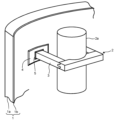
図3は、第1の実施形態に係る超音波探傷装置の検査対象の例としてのライザ管のライザーブレースアームとその取り付け部を示す斜視図である。図4は、第1の実施形態に係る超音波探傷装置の対象部位としての平板の溶接部とその周辺を示す平面図、図5は、側面図である。 FIG. 3 is a perspective view showing a riser brace arm of a riser pipe as an example of an object to be inspected by the ultrasonic flaw detector according to the first embodiment and a mounting portion thereof. FIG. 4 is a plan view showing a plate welded portion and its surroundings as a target portion of the ultrasonic flaw detector according to the first embodiment, and FIG. 5 is a side view.
原子炉圧力容器1は、原子炉圧力容器母材1aと、原子炉圧力容器内面ライナ(第1の溶接層)1bすなわち原子炉圧力容器母材1aの内面に施された肉盛溶接部とを有する。
The
原子炉圧力容器母材1aは、主に低合金鋼であるが、一般的な炭素鋼やオーステナイト系ステンレス鋼やニッケル基合金等、あるいはその他の金属であってもよい。
The reactor pressure
原子炉圧力容器内面ライナ1bは、TIG溶接、MIG溶接、MAG溶接、被覆アーク溶接、レーザ溶接、サブマージアーク溶接、エレクトロスラグ溶接等が考えられ、材料もオーステナイト系ステンレス鋼、ニッケル基合金に加え、一般的な炭素鋼や低合金鋼等であってもよい。また、肉盛りを複数層で行う場合、例えば初層等、所望の層において異なる材料や工法を用いたものでもよい。
TIG welding, MIG welding, MAG welding, shielded arc welding, laser welding, submerged arc welding, electroslag welding, etc. can be considered for the reactor pressure vessel
また、第1の溶接層である原子炉圧力容器内面ライナ1bの表面に形成される第2の溶接層4についても、施工法および材料は、原子炉圧力容器内面ライナ1bと同様である。
The construction method and materials for the
沸騰水型原子炉においては、図示しないジェットポンプへの原子炉冷却材の供給側の配管であるライザ管2aがライザーブレースアーム2によって、原子炉圧力容器1の内壁に取り付けられている。ライザーブレースアーム2のうち、直接、原子炉圧力容器1の内壁に取り付けられるのは、平板3である。
In a boiling water reactor, a
平板3は、溶接により取り付けられる。また、平板3の取付け部分には、原子炉圧力容器内面ライナ1bの表面(原子炉圧力容器1の内表面)に、さらに、平板状の第2の溶接層4が形成されている。したがって、平板3の取付け部分には、第1の溶接層である原子炉圧力容器内面ライナ1b、第2の溶接層4、および第3の溶接層である平板溶接層5が形成されている。
The
ここで、第3の溶接層である平板溶接層5は、フルペネトレーションの開先による完全溶け込み溶接部である。溶接金属終端部から所定の範囲は、平板3の全長以下であれば任意に定める範囲でよく、例えば1インチ、25mm、2インチや50mm等を超音波探傷に求められる範囲としてよい。
Here, the
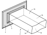
図6は、第1の実施形態に係る超音波探傷装置の対象部位としての平板の溶接部とその周辺を示す斜視図である。また、図7は、第1の実施形態に係る超音波探傷装置の対象部位としての平板の溶接部の溶接基準線長辺部を説明するための概念的な平面図、図8は、概念的な側面図である。図6ないし図8では、第1の溶接層1bの図示は省略している。
FIG. 6 is a perspective view showing a welded portion of a flat plate as a target portion of the ultrasonic flaw detector according to the first embodiment and its surroundings. Further, FIG. 7 is a conceptual plan view for explaining the weld reference line long side portion of the flat plate weld portion as the target portion of the ultrasonic flaw detector according to the first embodiment, and FIG. is a side view. 6 to 8, illustration of the first welded
平板3は、断面が長方形の板であり、幅の広い2つの長辺側面3aと、幅の狭い2つの短辺側面3bとを有する。ここで、溶接基準線長辺部8aおよび溶接基準線短辺部8bの2種類の溶接基準線を定義する。
The
具体的には、溶接基準線長辺部8aおよび溶接基準線短辺部8bを、平板3の2つの長辺側面3aと2つの短辺側面3bのそれぞれの延長面と仮想平面Sとの交線のそれぞれ、長辺部を溶接基準線長辺部8aとし、短辺部を溶接基準線短辺部8bとして、導かれたものとして定義する。
Specifically, the weld reference line
ここで、仮想平面Sは、図7に示すように、第3の溶接層である平板溶接層5の互いに反対側の部分、たとえば、平板3の2つの長辺側面3a側の部分、あるいは平板3の2つの短辺側面3b側の部分の、それぞれの表面ビード幅中点どうしを含む面である。あるいは、仮想平面Sとして、当該平板3の取り付け部における原子炉圧力容器1の内面の接平面に平行な面であって、第2の溶接層4から、平板3の長手方向に沿った平板溶接層5の脚長の半分の高さだけ離れた面としてもよい。
Here, as shown in FIG. 7, the virtual plane S is the portion of the flat
以下、上記のように構成した本実施形態による超音波探傷装置100の作用について説明する。
The operation of the
まず、外側探傷機構110の作用を説明する。
First, the action of the outer
図9は、第1の実施形態に係る超音波探傷装置の対象部位への超音波の主音線の第1の進行状態を説明するための概念的な図10のIX-IX線矢視断面図、図10は、平面図、図11は、図10のXI-XI線矢視断面図である。 FIG. 9 is a conceptual cross-sectional view taken along line IX-IX of FIG. 10 for explaining a first progressing state of the principal sound ray of the ultrasonic wave to the target portion of the ultrasonic flaw detection apparatus according to the first embodiment. 10 is a plan view, and FIG. 11 is a cross-sectional view taken along the line XI-XI in FIG.
プローブ10から、検査対象11に超音波を出射した状態を示している。実線矢印は、主音線12を示す。ここで、主音線12は、ベクトルUである。また、プローブ10は、本実施形態においては、図1に示すように、外側プローブ111または内側プローブ121であり、図10に示すようにx軸およびy軸方向に沿って配置されている。また、検査対象11は、平板3および平板溶接層5である。また、以下、説明の便宜上、図9における上下方向を鉛直方向、左右方向を水平方向と呼ぶこととする。後述する図12ないし図14についても同様である。
A state in which ultrasonic waves are emitted from the
ここで、主音線12を含めて、体系の基準となる面を基準面11aと定義する。図9ないし図11では、基準面11aとして検査対象11の水平表面をとった場合を例にとって示している。これは、具体的には、たとえば、外側プローブ111から超音波を入射する面、すなわち、原子炉圧力容器母材1aの外側表面である。例えば半径が1mを超えるような緩やかな曲面は平面で近似してもよい。また、外側プローブ111の最下面等、管理したい座標系に応じて他の面を基準面としてもよい。
Here, a plane that serves as a reference for the system including the
図9ないし図11に示す第1の進行状態においては、プローブ10からの主音線12は、x軸に沿って、基準面11aすなわち検査対象11の表面に、基準面11aに垂直な方向(鉛直方向)に対して角度αの方向で入射し、検査対象11内を、基準面11aに垂直な方向(鉛直方向)に対して角度βの方向に進んでいる。
9 to 11, the
ベクトルUで表示する主音線12は、主音線水平成分Uhと主音線鉛直成分Uvとに分解できる。すなわち、主音線12を基準面11aに投影した主音線水平成分Uhと、これに垂直な方向の主音線鉛直成分Uvとに分解できる。
The
図12は、第1の実施形態に係る超音波探傷装置の対象部位への超音波の主音線の第2の進行状態を説明するための概念的な図13のXII-XII線矢視断面図、図13は、平面図、図14は、図13のXIV-XIV線矢視断面図である。 FIG. 12 is a conceptual cross-sectional view taken along line XII-XII of FIG. 13 for explaining a second progress state of the principal sound ray of the ultrasonic wave to the target portion of the ultrasonic flaw detector according to the first embodiment; 13 is a plan view, and FIG. 14 is a cross-sectional view taken along line XIV-XIV of FIG.
図12ないし図14に示す第2の進行状態においては、プローブ10からの主音線は、x軸に対して平面的に角度γだけずれた方向で、基準面11aすなわち検査対象11の表面に、基準面11aに垂直な方向(鉛直方向)に対して角度αの方向で入射し、検査対象11内を、基準面11aに垂直な方向(鉛直方向)に対して角度βの方向に進んでいる。
In the second traveling state shown in FIGS. 12 to 14, the principal sound ray from the
ベクトルUで表示する主音線12は、主音線水平成分Uhと主音線鉛直成分Uvとに分解できる。すなわち、主音線12を基準面11aに投影した主音線水平成分Uhと、これに垂直な方向の主音線鉛直成分Uvとに分解できる。また、主音線水平成分Uhは、x方向成分Uhxとy方向成分Uhyとに分解できる。
The
図15は、第1の実施形態に係る超音波探傷装置の対象部位がライザ管のライザーブレースアームの場合の説明のための超音波の進行方向と欠陥の方向との第1の関係を示す概念的な斜視図であり、図16は、平面図である。 FIG. 15 is a concept showing a first relationship between the traveling direction of ultrasonic waves and the direction of defects for explanation when the target portion of the ultrasonic testing apparatus according to the first embodiment is the riser brace arm of the riser pipe. 16 is a perspective view, and FIG. 16 is a plan view.
図15に示す場合は、検査対象11における溶接線13の方向は、主音線12の方向と、ほぼ直交している。
In the case shown in FIG. 15 , the direction of the
以下、溶接線13の位置および方向は、それぞれ図7および図8を用いて説明した溶接基準線長辺部8aおよび溶接基準線短辺部8bの定義に基づいて設定されるものである。以下、図21、22、図30、31等においても同様である。
Hereinafter, the position and direction of the
主音線12および溶接線13を、基準面11aに投影すると、図16の平面図と同様の関係となる。このように、基準面11aに投影された溶接線13と、基準面11aに投影された主音線12のベクトルの水平成分Uhとは、同様にほぼ直交している。
When the
ここで、溶接線13と主音線12との直交方向の探傷条件を、溶接線13と主音線12とがほぼ直交する状態が確保されることと定義する。ここで、ほぼ直交するとは、基準面11aに投影された溶接線13と主音線12の水平成分Uhのなす交差角度Θが、90°を含む所定の範囲内にある場合をいう。所定の範囲としては、たとえば、90°±20°の範囲としてもよい。
Here, the flaw detection condition in the orthogonal direction between the
図17は、第1の実施形態に係る超音波探傷装置の対象部位がライザ管のライザーブレースアームの場合の溶接部の欠陥の第1の例を示す斜視図、図18は、平面図、図19は、側面図である。 17 is a perspective view showing a first example of a defect in a welded portion when the target portion of the ultrasonic flaw detector according to the first embodiment is a riser brace arm of a riser pipe, and FIG. 18 is a plan view and a diagram. 19 is a side view.
外側探傷機構110による探傷において、溶接線と直交方向の探傷条件を用いた場合、融合不良、ブローホール、スラグ巻き込み等といった種々の溶接欠陥や、溶接線と平行方向に進展する割れ、応力腐食割れ等の経年的に発生する割れを検出することができる。また、水素フレーキングのような原子炉特有の欠陥検出にも有効である。
In the flaw detection by the outer
ここで、欠陥は、図17および図18に示す平板溶接層5に生じた横割れ欠陥3d、図17および図19に示す平板3に生じた横割れ欠陥3eである。横割れ欠陥3dおよび横割れ欠陥3eのいずれも、平板3の長手方向に垂直な方向、すなわち、原子炉圧力容器1の拡がる方向に平行に延びている。
Here, the defects are a
図20は、第1の実施形態に係る超音波探傷装置の対象部位がライザ管のライザーブレースアームの場合の説明のための超音波の進行方向と欠陥の方向との第2の関係を示す概念的な斜視図であり、図21は、平面図である。 FIG. 20 is a concept showing a second relationship between the traveling direction of ultrasonic waves and the direction of defects for explanation when the target portion of the ultrasonic testing apparatus according to the first embodiment is the riser brace arm of the riser pipe. 21 is a perspective view, and FIG. 21 is a plan view.
図20に示す場合は、検査対象11における溶接線13の方向は、主音線12の方向と、ほぼ同じ方向である。主音線12および溶接線13を、基準面11aに投影すると、図21の平面図と同様の関係となる。このように、基準面11aに投影された溶接線13と、基準面11aに投影された主音線12のベクトルの水平成分Uhとは、同様にほぼ同じ方向を向いている。
In the case shown in FIG. 20 , the direction of the
ここで、溶接線13と主音線12との平行方向の探傷条件を、溶接線13の方向と主音線12の方向がほぼ一致する、すなわちほぼ平行となる状態が確保されることと定義する。ここで、ほぼ平行となるとは、基準面11aに投影された溶接線13と主音線12の水平成分Uhのなす交差角度Θが、0°を含む所定の範囲内にある場合をいう。所定の範囲としては、たとえば、0°±20°の範囲としてもよい。
Here, the flaw detection condition for the parallel direction of the
図22は、第1の実施形態に係る超音波探傷装置の対象部位がライザ管のライザーブレースアームの場合の溶接部の欠陥の第2の例を示す斜視図であり、図23は、平面図、図24は、側面図である。 FIG. 22 is a perspective view showing a second example of a weld defect when the target portion of the ultrasonic flaw detector according to the first embodiment is a riser brace arm of a riser pipe, and FIG. 23 is a plan view. 24 is a side view.
外側探傷機構110による探傷において、溶接線と平行方向の探傷条件を用いた場合にも、融合不良、ブローホール、スラグ巻き込み等といった種々の溶接欠陥や、溶接線と直交する方向に進展する割れ、応力腐食割れ等の経年的に発生する割れを検出することができる。また、水素フレーキングのような原子炉特有の欠陥検出にも有効である。
In flaw detection by the outer
ここで、欠陥は、図22および図23に示す平板溶接層5から平板3に亘って生じた縦割れ欠陥3f、図22および図24に示す平板溶接層5に生じた縦割れ欠陥3gである。縦割れ欠陥3fおよび縦割れ欠陥3gのいずれも、平板3の長手方向に平行な方向、すなわち、原子炉圧力容器1の拡がる方向に垂直な方向に延びている。
Here, the defects are a
次に、内側探傷機構120の作用を説明する。
Next, the action of the inner
図25は、第1の実施形態に係る超音波探傷装置の対象部位がライザ管のライザーブレースアームの場合の超音波の発信方向の第1の例を示す平面図であり、図26は、縦断面図、図27は、第1の例の変形例を示す縦断面図である。 FIG. 25 is a plan view showing a first example of the transmission direction of ultrasonic waves when the target portion of the ultrasonic testing apparatus according to the first embodiment is a riser brace arm of a riser pipe, and FIG. FIG. 27 is a vertical sectional view showing a modification of the first example.
内側プローブ121は、原子炉圧力容器1の内側の平板3の長辺側面3aの表面あるいは第3の溶接層である平板溶接層5上に設置される。
The
内側プローブ121から発せられ平板3の内部に入射した超音波は、平板3内を伝搬した後に、平板溶接層5に到達する。平板3への入射角度によっては、図27に示すように、内側プローブ121が設置されている入射側の長辺側面3aとは反対側の長辺側面3aで反射した後に、平板溶接層5に到達する。
The ultrasonic waves emitted from the
内側プローブ121については、基準面は平板3の長辺側面3aもしくは平板溶接層5の平板溶接長辺部5aをとることができる。あるいは、内側プローブ121の最下面等、管理したい座標系に応じてその他の面をとってもよい。
As for the
外側プローブ111と同様に、内側プローブ121においても、主音線Uは主音線水平成分Uhと主音線鉛直成分Uvとに分解できる。このとき、内側プローブ121は、スキップ、すなわち、例えば平板3の対面(図27で下側の長辺側面3a)や設置表面(図27で上側の長辺側面3a)で1回以上超音波を反射させて伝搬させることもできる。このときでも、主音線水平成分Uhは主音線Uを基準面に投影した2次元の成分となることは同様である。
As with the
内側プローブ121から得られる主音線Uと溶接線13の幾何関係に基づく平行方向の探傷条件、直交方向の探傷条件については、外側プローブ111の場合と同様に定義できる。しかしながら、内側プローブ121の場合は、外側プローブ111の場合に対して制約がある。
Parallel direction flaw detection conditions and orthogonal direction flaw detection conditions based on the geometrical relationship between the principal sound line U obtained from the
図28は、第1の実施形態に係る超音波探傷装置の対象部位がライザ管のライザーブレースアームの場合の超音波の発信方向の第2の例を示す平面図、図29は、縦断面図である。 FIG. 28 is a plan view showing a second example of the transmission direction of ultrasonic waves when the target portion of the ultrasonic testing apparatus according to the first embodiment is a riser brace arm of a riser pipe, and FIG. 29 is a vertical cross-sectional view. is.
図28および図29に示すように、内側プローブ121は、平板3の長辺側面3aの表面あるいは第3の溶接層である平板溶接層5上に設置されるものである。
As shown in FIGS. 28 and 29, the
平板溶接層5の溶接線のうち、平板溶接長辺部5aについては、基準面とほぼ平行な方向に形成されている。一方、平板溶接短辺部5bについては、平行方向の探傷条件および直交方向の探傷条件のいずれも成立することが困難である。これを、図を用いて説明する。
Of the weld line of the flat
図30は、第1の実施形態に係る超音波探傷装置の対象部位がライザ管のライザーブレースアームの場合の説明のための超音波の進行方向と欠陥の方向との第3の関係を示す概念的な斜視図であり、図31は、平面図である。 FIG. 30 is a concept showing a third relationship between the traveling direction of ultrasonic waves and the direction of defects for explanation when the target portion of the ultrasonic testing apparatus according to the first embodiment is the riser brace arm of the riser pipe. 31 is a perspective view, and FIG. 31 is a plan view.
図30および図31において、プローブ10は、検査対象11の上面に設置されており、この上面が基準面11aとなる。プローブ10から発せられ検査対象11内に入射した超音波の主音線12のベクトルUを基準面11aへ投影した成分は水平成分Uhとなる。
30 and 31, the
いま、溶接線13が、検査対象11において、図30の上下方向に形成されている場合、この溶接線13の基準面11aへの投影は、図31に示すように、点状となる。
Now, when the
したがって、このような溶接線13の場合には、基準面11aへ投影された主音線12と溶接線13との関係から明らかなように、直交方向の探傷条件および平行方向の探傷条件のいずれの条件も、満たすことができない。
Therefore, in the case of such a
このような主音線12と溶接線13との関係は、図28に示す平板溶接層5の平板溶接長辺部5aの上に設置され内側プローブ121と、平板溶接層5の平板溶接短辺部5bとの関係と同じである。
The relationship between the
したがって、内側プローブ121を用いた場合、平板溶接層5の平板溶接短辺部5bについては、内側プローブ121から発せられる主音線12の水平成分Uhと直交および平行方向の探傷条件を形成することはできない。そのため、本実施形態においては、平板溶接層5の平板溶接短辺部5bについて直交方向の探傷条件もしくは平行方向の探傷条件を形成可能なのは、外側プローブ111に限られることとなる。
Therefore, when the
図32は、第1の実施形態に係る超音波探傷方法の手順を示すフロ―図である。 FIG. 32 is a flowchart showing the procedure of the ultrasonic flaw detection method according to the first embodiment.
超音波探傷方法は、内側探傷機構120による探傷(ステップS10)、外側探傷機構110による探傷(ステップS20)、および照合・確認(ステップS30)を有する。 The ultrasonic flaw detection method includes flaw detection by the inner flaw detection mechanism 120 (step S10), flaw detection by the outer flaw detection mechanism 110 (step S20), and collation/confirmation (step S30).
ここで、図32では、内側探傷機構120による探傷(ステップS10)の後に外側探傷機構110による探傷(ステップS20)を実施する場合を例にとって示しているが、外側探傷機構110による探傷(ステップS20)の後に内側探傷機構120による探傷(ステップS10)を実施することでもよい。 Here, FIG. 32 shows an example in which flaw detection by the inner flaw detection mechanism 120 (step S10) is followed by flaw detection by the outer flaw detection mechanism 110 (step S20). ) may be performed by the inner flaw detection mechanism 120 (step S10).
内側探傷機構120による探傷(ステップS10)においては、まず、内側プローブ121を平板3の長手方向に沿って設置する(ステップS11)。次に、この状態で、内側プローブ121を用いた探傷を実施する(ステップS12)。次に、内側プローブ121を平板溶接長辺部5aに沿って設置する(ステップS13)。次に、この状態で、内側プローブ121を用いた探傷を実施する(ステップS14)。なお、ステップS11およびステップS12と、ステップS13およびステップS14とは、順序を逆にして、ステップS13、ステップS14、ステップS11、ステップS12の順に実施してもよい。
In the flaw detection by the inner flaw detection mechanism 120 (step S10), first, the
外側探傷機構110による探傷(ステップS20)においては、まず、外側プローブ111を原子炉圧力容器1の長手方向に沿って設置する(ステップS21)。次に、この状態で、外側プローブ111を用いた探傷を行う(ステップS22)。
In the flaw detection by the outer flaw detection mechanism 110 (step S20), first, the
照合・確認(ステップS30)は、ステップS10およびステップS20の両者が終了した後に実施する。照合・確認(ステップS30)は、平板3および平板溶接長辺部5aについて、内側探傷機構120による探傷(ステップS10)の結果と、外側探傷機構110による探傷(ステップS20)の結果を、照合し、確認するステップS31を有する。
Collation/confirmation (step S30) is performed after both steps S10 and S20 are completed. In the collation/confirmation (step S30), the result of the flaw detection (step S10) by the inner
以上のことから、平板3および平板溶接層5を検査対象11として超音波探傷を実施する場合は、外側プローブ111および内側プローブ121の両者を用いて行う必要があるため、外側探傷機構110および内側探傷機構120を用いる本実施形態における超音波探傷装置100および超音波探傷方法が有効であり、アクセス性の限られた部位を、確実に探傷することができる。
From the above, when ultrasonic flaw detection is performed on the
[第2の実施形態]
図33は、第2の実施形態に係る超音波探傷装置の構成を示す縦断面図である。
[Second embodiment]
FIG. 33 is a vertical cross-sectional view showing the configuration of an ultrasonic flaw detector according to the second embodiment.
本実施形態は、第1の実施形態の変形であり、設置角度補正機構130をさらに備える。その他の点では、第1の実施形態と同様である。
This embodiment is a modification of the first embodiment, and further includes an installation
設置角度補正機構130は、外側設置角度判定部131a、外側補正演算部132a、外側補正動作部133a、および、内側設置角度判定部131b、内側補正演算部132b、および内側補正動作部133bを有する。
The installation
外側設置角度判定部131aは、外側プローブ111と超音波入射面のなす角度を設置角度φ1とし、設置角度φ1が所定の角度Φ10の誤差範囲に収まっているか否かを判定する。外側補正演算部132aは、外側設置角度判定部131aにより得られた設置角度Φ1を、所定の角度Φ10の誤差範囲内に納めるための補正計算を行う。外側補正演算部132aは、補正計算結果に基づく補正動作指令を外側補正動作部133aに出力し、外側補正動作部133aは補正動作を行う。
The outer installation angle determination unit 131a determines whether or not the installation angle φ1 is within the error range of the predetermined angle Φ10, with the installation angle φ1 being the angle between the
内側設置角度判定部131bは、内側プローブ121と超音波入射面のなす角度を設置角度φ2とし、設置角度φ2が所定の角度Φ20の誤差範囲に収まっているか否かを判定する。内側補正演算部132bは、内側設置角度判定部131bにより得られた設置角度Φ2を、所定の角度Φ20の誤差範囲内に納めるための補正計算を行う。内側補正演算部132bは、補正計算結果に基づく補正動作指令を内側補正動作部133bに出力し、内側補正動作部133bは補正動作を行う。
The inner installation
ここで、外側設置角度判定部131aおよび内側設置角度判定部131bによる判定方法については、たとえば、プローブそのものから発せられる超音波を用いる第1の方式と、それ以外の機構を備える第2の方式がある。
Here, regarding the determination method by the outer installation angle determination unit 131a and the inner installation
まず、設置角度Φが、所期の範囲内にあるか否かを判定する第1の方式について説明する。 First, a first method for determining whether or not the installation angle Φ is within a desired range will be described.
図34は、第2の実施形態に係る超音波探傷装置による超音波の進行を示す縦断面図であり、図35は、超音波信号強度の時間変化を示すグラフである。図34および図35は、設置角度Φが、所期の範囲内にある場合を示す。 FIG. 34 is a vertical cross-sectional view showing the progress of ultrasonic waves by the ultrasonic flaw detector according to the second embodiment, and FIG. 35 is a graph showing temporal changes in ultrasonic signal intensity. 34 and 35 show the case where the installation angle Φ is within the desired range.
図35における超音波信号強度の時間的強度の最初のピークは、検査対象11の表面である基準面111aでの反射波に対応する。この場合、最初のピークの値は、強度レベルA1より高く強度レベルA2より小さい、すなわち、強度レベルA1と強度レベルA2の間にある。 The first peak of the temporal intensity of the ultrasonic signal intensity in FIG. In this case, the value of the first peak is above intensity level A1 and below intensity level A2, ie between intensity level A1 and intensity level A2.
図36は、第2の実施形態に係る超音波探傷装置が所期の範囲から傾いている場合の超音波の進行を示す縦断面図であり、図37は、超音波信号強度の時間変化を示すグラフである。設置角度Φが所期の角度範囲内になく、その範囲から逸脱して傾いているこのケースの場合、基準面111aからの反射波のプローブ10への戻り量が減少する。この場合、図37に示すように、超音波信号強度の時間変化の最初のピークの値が低下する。この結果、最初のピーク値が、強度レベルA1よりも低くなる。
FIG. 36 is a vertical cross-sectional view showing the progress of ultrasonic waves when the ultrasonic flaw detection apparatus according to the second embodiment is tilted from the desired range, and FIG. It is a graph showing. In this case, where the installation angle Φ is not within the desired angle range and tilts out of that range, the amount of reflected waves from the
このように、設置角度Φが所期の角度範囲内にある場合と所期の範囲内にない場合とで、最初のピーク値が、それぞれ、強度レベルA1よりも高くなり、低くなるように、強度レベルA1の値を設定することにより、設置角度Φが所期の角度範囲内にあるか否かを判定することができる。 In this way, when the installation angle Φ is within the desired angle range and when it is not within the desired range, the first peak value is higher and lower than the intensity level A1, respectively. By setting the value of the intensity level A1, it can be determined whether the installation angle Φ is within the desired angle range.
また、プローブ10から発せられて基準面111aで反射した反射波のプローブ10戻るまでの伝搬時間は、設置角度Φが所期の範囲内にない場合には、設置角度Φが所期の角度範囲内にある場合に比べて、長くなる。したがって、図35に示す設置角度Φが所期の角度範囲内にある場合における最初のピークのゼロクロス時刻T1に対して、図37に示すように有意な遅れがある場合には、設置角度Φが所期の角度範囲内にないと判定することができる。なお、最初のピークの立ち上がり時刻T1に代えて立ち上がり時刻を用いてもよい。
In addition, the propagation time of the reflected wave emitted from the
このように、反射波の最初のピークの強度に加えて、その時刻を併せて用いることにより、設置角度Φが所期の角度範囲内にあるか否かについて、さらに確実な判定をすることができる。 In this manner, by using the time of the first peak of the reflected wave in addition to the intensity of the first peak, it is possible to more reliably determine whether or not the installation angle Φ is within the desired angle range. can.
また、例えばアレイプローブであれば、複数素子から発せられた超音波の伝搬時間を測定することで、定量的な傾き量や表面の凹凸も測定することができる。 Further, for example, in the case of an array probe, by measuring the propagation time of ultrasonic waves emitted from a plurality of elements, it is possible to quantitatively measure the amount of inclination and the unevenness of the surface.
さらに、表示部に表示された超音波信号の波形をみて、設置角度Φが所期の角度範囲内にあるか否かの判定を行ってもよい。 Furthermore, it may be determined whether or not the installation angle Φ is within the desired angle range by looking at the waveform of the ultrasonic signal displayed on the display unit.
次に、設置角度Φが所期の範囲内にあるか否かを判定する第2の方式については、例えばレーザ距離計、超音波距離計、カメラ等のような非接触距離測定手段でもよいし、リミットスイッチやスペーサ等のような機械的に接触する手段でもよい。 Next, as for the second method for determining whether or not the installation angle Φ is within the desired range, non-contact distance measuring means such as a laser rangefinder, an ultrasonic rangefinder, or a camera may be used. , a mechanical contact means such as a limit switch, a spacer, or the like.
外側設置角度判定部131aおよび内側設置角度判定部131bに関するこのような手段は、外側探傷機構110であれば外側プローブ111または外側プローブ保持駆動機構112に、内側探傷機構120であれば内側プローブ121または内側プローブ保持駆動機構122に、あるいは検査対象11そのものに取り付けてもよい。
Such means relating to the outer installation angle determination unit 131a and the inner installation
外側設置角度判定部131aおよび内側設置角度判定部131bは、上述の第1の方式と第2の方式を組み合わせてもよい。あるいは、外側プローブ111および内側プローブ121の複数の設置場所での結果を組み合わせて用いてもよい。
The outer installation angle determination section 131a and the inner installation
次に、設置角度補正機構130の外側補正演算部132aおよび内側補正演算部132bの内容を説明する。
Next, the contents of the outer
図38は、第2の実施形態に係る超音波探傷装置が所期の範囲より傾いている場合の超音波の入射方向の修正を説明する縦断面図である。また、図39は、第2の実施形態に係る超音波探傷装置が所期の範囲より傾いている場合の超音波の入射方向の修正を行った結果を示す縦断面図である。 FIG. 38 is a vertical cross-sectional view for explaining correction of the incident direction of ultrasonic waves when the ultrasonic testing apparatus according to the second embodiment is tilted beyond the intended range. FIG. 39 is a vertical cross-sectional view showing the result of correcting the incident direction of ultrasonic waves when the ultrasonic flaw detector according to the second embodiment is tilted beyond the expected range.
外側補正演算部132aおよび内側補正演算部132bについても、大きく2つのパターンが考えられる。
Broadly speaking, two patterns are conceivable for the outer
第1のパターンは、プローブ10そのものから発せられる超音波を用いる方式である。プローブ10から発せられる超音波を用いる場合は、特にアレイプローブを用いる場合に相性がよい。図39に示すように、設置角度φを加味して入射角αを調節することで最終的な屈折角βを所望の角度とすることができる。外側補正演算部132aおよび内側補正演算部132bは、所望する屈折角βと設置角度Φに基づいて、入射角αを導出する。
The first pattern is a method using ultrasonic waves emitted from the
第2のパターンは、外側補正演算部132aおよび内側補正演算部132bは、入射角αを順次変更する演算を行い、外側機構制御部115および内側機構制御部125にそれぞれ出力し、実際に入射角αを順次変化させる方式である。
In the second pattern, the outer
外側補正動作部133aおよび内側補正動作部133bは、外側補正演算部132aおよび内側補正演算部132bが算出した補正量に基づいて、それぞれ、補正動作を行う。
The outer
外側補正動作部133aおよび内側補正動作部133bは、図33に示すように、それぞれ、外側プローブ111および内側プローブ121のそれぞれに直接結合して、それぞれからの超音波の入射角αを変化させる。
As shown in FIG. 33, the outer
なお、外側補正動作部133aおよび内側補正動作部133bは、例えば回転ステージ、ゴニオステージのような回転機構を有するものとして、それぞれ、外側プローブ保持駆動機構112および内側プローブ保持駆動機構122を駆動することによって最終的な屈折角βを所望の角度とする方式としてもよい。
Note that the outer
以上のように、本第2の実施形態においては、設置角度を補正することにより、所期の角度範囲内で主音線を伝搬させることができ、さらに超音波探傷を確実に実施することができる。 As described above, in the second embodiment, by correcting the installation angle, the principal sound ray can be propagated within the desired angle range, and the ultrasonic flaw detection can be reliably performed. .
[その他の実施形態]
以上、本発明の実施形態を説明したが、実施形態は、例として提示したものであり、発明の範囲を限定することは意図していない。
[Other embodiments]
Although the embodiments of the present invention have been described above, the embodiments are presented as examples and are not intended to limit the scope of the invention.
また、各実施形態の特徴を組み合わせてもよい。また、実施形態は、その他の様々な形態で実施されることが可能であり、発明の要旨を逸脱しない範囲で、種々の省略、置き換え、変更を行うことができる。 Moreover, you may combine the characteristic of each embodiment. In addition, the embodiments can be implemented in various other forms, and various omissions, replacements, and modifications can be made without departing from the scope of the invention.
実施形態やその変形は、発明の範囲や要旨に含まれると同様に、特許請求の範囲に記載された発明とその均等の範囲に含まれるものである。 The embodiments and their modifications are included in the scope and spirit of the invention, as well as the scope of the invention described in the claims and its equivalents.
1…原子炉圧力容器、1a…原子炉圧力容器母材、1b…原子炉圧力容器内面ライナ(第1の溶接層)、2…ライザーブレースアーム、2a…ライザ管、3…平板、3a…長辺側面、3b…短辺側面、3d、3e…横割れ欠陥、3f、3g…縦割れ欠陥、4…第2の溶接層、5…平板溶接層(第3の溶接層)、5a…平板溶接長辺部、5b…平板溶接短辺部、8…溶接基準線、8a…溶接基準線長辺部、8b…溶接基準線短辺部、10…プローブ、11…検査対象、12…主音線、13…溶接線、100…超音波探傷装置、105…全体制御部、110…外側探傷機構、111…外側プローブ、112…外側プローブ保持駆動機構、113…外側超音波探傷器、114…外側監視操作部、115…外側機構制御部、118…遠隔目視機構、120…内側探傷機構、121…内側プローブ、122…内側プローブ保持駆動機構、123…内側超音波探傷器、124…内側監視操作部、125…内側機構制御部、130…設置角度補正機構、131a…外側設置角度判定部、131b…内側設置角度判定部、132a…外側補正演算部、132b…内側補正演算部、133a…外側補正動作部、133b…内側補正動作部
DESCRIPTION OF
Claims (9)
前記容器の外側から探傷する外側探傷機構と、
前記容器の内側から探傷する内側探傷機構と、
を備え、
前記外側探傷機構は、
前記容器の外側に配される外側プローブと、
前記外側プローブを保持する外側プローブ保持駆動機構と、
前記外側プローブによる超音波の受発信を駆動し前記検査対象からの反射波に基づいて信号処理を行う外側超音波探傷器と、
を有し、
前記内側探傷機構は、
前記容器の内側に配される内側プローブと、
前記内側プローブを保持する内側プローブ保持駆動機構と、
前記内側プローブによる超音波の受発信を駆動し前記検査対象からの反射波に基づいて信号処理を行う内側超音波探傷器と、
を有し、
前記検査対象は、その内面に第1の溶接層が形成された原子炉圧力容器の内側において、前記第1の溶接層の上に形成された第2の溶接層の上に完全溶け込みの全周溶接による第3の溶接層で接合され長辺部と短辺部とを有する平板および前記第3の溶接層である、
ことを特徴とする超音波探傷装置。 An ultrasonic flaw detector for detecting defects to be inspected inside a container,
an outer flaw detection mechanism that detects flaws from the outside of the container;
an inner flaw detection mechanism that detects flaws from the inside of the container;
with
The outer flaw detection mechanism is
an outer probe arranged outside the container;
an outer probe holding drive mechanism that holds the outer probe;
an outer ultrasonic flaw detector that drives transmission and reception of ultrasonic waves by the outer probe and performs signal processing based on reflected waves from the inspection object;
has
The inner flaw detection mechanism is
an inner probe disposed inside the container;
an inner probe holding drive mechanism that holds the inner probe;
an inner ultrasonic flaw detector that drives transmission and reception of ultrasonic waves by the inner probe and performs signal processing based on reflected waves from the inspection object;
has
The inspection object is a full-penetration perimeter above a second weld layer formed on the first weld layer inside a reactor pressure vessel having a first weld layer formed on the inner surface. A flat plate joined by a third welding layer by welding and having a long side and a short side and the third welding layer,
An ultrasonic flaw detector characterized by:
内側探傷機構を用いて前記容器の内側から探傷する内側探傷ステップと、
外側探傷機構を用いて前記容器の外側から探傷する外側探傷ステップと、
を有し、
前記外側探傷機構は、
前記容器の外側に配される外側プローブと、
前記外側プローブを保持する外側プローブ保持駆動機構と、
前記外側プローブによる超音波の受発信を駆動し前記検査対象からの反射波に基づいて信号処理を行う外側超音波探傷器と、
を有し、
前記内側探傷機構は、
前記容器の内側に配される内側プローブと、
前記内側プローブを保持する内側プローブ保持駆動機構と、
前記内側プローブによる超音波の受発信を駆動し前記検査対象からの反射波に基づいて信号処理を行う内側超音波探傷器と、
を有し、
前記検査対象は、その内面に第1の溶接層が形成された原子炉圧力容器の内側において、前記第1の溶接層の上に形成された第2の溶接層の上に完全溶け込みの全周溶接による第3の溶接層で接合され長辺部と短辺部とを有する平板および前記第3の溶接層である、
ことを特徴とする超音波探傷方法。 An ultrasonic flaw detection method for detecting defects to be inspected inside a container,
an inner flaw detection step of detecting flaws from the inside of the container using an inner flaw detection mechanism;
an outer flaw detection step of detecting flaws from the outside of the container using an outer flaw detection mechanism;
has
The outer flaw detection mechanism is
an outer probe arranged outside the container;
an outer probe holding drive mechanism that holds the outer probe;
an outer ultrasonic flaw detector that drives transmission and reception of ultrasonic waves by the outer probe and performs signal processing based on reflected waves from the inspection object;
has
The inner flaw detection mechanism is
an inner probe disposed inside the container;
an inner probe holding drive mechanism that holds the inner probe;
an inner ultrasonic flaw detector that drives transmission and reception of ultrasonic waves by the inner probe and performs signal processing based on reflected waves from the inspection object;
has
The inspection object is a full-penetration perimeter above a second weld layer formed on the first weld layer inside a reactor pressure vessel having a first weld layer formed on the inner surface. A flat plate joined by a third welding layer by welding and having a long side and a short side and the third welding layer,
An ultrasonic flaw detection method characterized by:
前記内側プローブを前記検査対象としての平板の長手方向に沿って設置する内側プローブ第1設置ステップと、
前記内側プローブ第1設置ステップの後に前記内側プローブを用いて探傷する内側プローブ第1探傷ステップと、
前記内側プローブを前記平板の溶接長辺部に沿って設置する内側プローブ第2設置ステップと、
前記内側プローブ第2設置ステップの後に前記内側プローブを用いて探傷する内側プローブ第2探傷ステップと、
を有することを特徴とする請求項6に記載の超音波探傷方法。 The inner flaw detection step includes:
an inner probe first installation step of installing the inner probe along the longitudinal direction of the flat plate to be inspected;
an inner probe first flaw detection step of performing flaw detection using the inner probe after the inner probe first installation step;
an inner probe second installation step of installing the inner probe along the weld long side of the flat plate;
an inner probe second flaw detection step of performing flaw detection using the inner probe after the inner probe second installation step;
The ultrasonic flaw detection method according to claim 6, characterized by comprising:
前記外側プローブを原子炉圧力容器の長手方向に沿って設置する外側プローブ設置ステップと、
前記外側プローブ設置ステップの後に前記外側プローブを用いて探傷する外側プローブ探傷ステップと、
を有することを特徴とする請求項6または請求項7に記載の超音波探傷方法。 The outer flaw detection step includes:
an outer probe installation step of installing the outer probe along the longitudinal direction of the reactor pressure vessel ;
an outer probe flaw detection step of performing flaw detection using the outer probe after the outer probe installation step ;
The ultrasonic flaw detection method according to claim 6 or 7, characterized by comprising :
Priority Applications (1)
| Application Number | Priority Date | Filing Date | Title |
|---|---|---|---|
| JP2019210543A JP7247076B2 (en) | 2019-11-21 | 2019-11-21 | Ultrasonic flaw detector and ultrasonic flaw detection method |
Applications Claiming Priority (1)
| Application Number | Priority Date | Filing Date | Title |
|---|---|---|---|
| JP2019210543A JP7247076B2 (en) | 2019-11-21 | 2019-11-21 | Ultrasonic flaw detector and ultrasonic flaw detection method |
Publications (2)
| Publication Number | Publication Date |
|---|---|
| JP2021081360A JP2021081360A (en) | 2021-05-27 |
| JP7247076B2 true JP7247076B2 (en) | 2023-03-28 |
Family
ID=75964914
Family Applications (1)
| Application Number | Title | Priority Date | Filing Date |
|---|---|---|---|
| JP2019210543A Active JP7247076B2 (en) | 2019-11-21 | 2019-11-21 | Ultrasonic flaw detector and ultrasonic flaw detection method |
Country Status (1)
| Country | Link |
|---|---|
| JP (1) | JP7247076B2 (en) |
Citations (1)
| Publication number | Priority date | Publication date | Assignee | Title |
|---|---|---|---|---|
| JP2008203203A (en) | 2007-02-22 | 2008-09-04 | Toshiba Corp | Method of accessing jet pump riser pipe welded portion |
Family Cites Families (6)
| Publication number | Priority date | Publication date | Assignee | Title |
|---|---|---|---|---|
| JPS57120856A (en) * | 1981-01-19 | 1982-07-28 | Chugoku Electric Power Co Ltd:The | Ultrasonic inspecting device |
| JPH04184252A (en) * | 1990-11-19 | 1992-07-01 | Mitsubishi Heavy Ind Ltd | Ultrasonic flaw detection |
| JPH04136565U (en) * | 1991-06-06 | 1992-12-18 | 石川島播磨重工業株式会社 | Ultrasonic flaw detection equipment |
| JPH0815236A (en) * | 1994-06-28 | 1996-01-19 | Tokimec Inc | Ultrasonic flaw detector |
| JP3069005B2 (en) * | 1994-07-18 | 2000-07-24 | 株式会社東芝 | Ultrasonic flaw detector in reactor |
| JPH0862194A (en) * | 1994-08-18 | 1996-03-08 | Daido Steel Co Ltd | Method and apparatus for inspection of bonded part |
-
2019
- 2019-11-21 JP JP2019210543A patent/JP7247076B2/en active Active
Patent Citations (1)
| Publication number | Priority date | Publication date | Assignee | Title |
|---|---|---|---|---|
| JP2008203203A (en) | 2007-02-22 | 2008-09-04 | Toshiba Corp | Method of accessing jet pump riser pipe welded portion |
Also Published As
| Publication number | Publication date |
|---|---|
| JP2021081360A (en) | 2021-05-27 |
Similar Documents
| Publication | Publication Date | Title |
|---|---|---|
| JP5155692B2 (en) | Ultrasonic inspection equipment | |
| JP5111277B2 (en) | Ultrasonic flaw detection apparatus and ultrasonic flaw detection method | |
| CN112763574B (en) | Phased array ultrasonic detection method for butt welded joint of aluminum alloy sheet | |
| JP4837425B2 (en) | Inspection method and apparatus for spot welds | |
| JP5662873B2 (en) | Ultrasonic flaw detection method | |
| US20180056447A1 (en) | System for evaluating weld quality using eddy currents | |
| JP4838697B2 (en) | Ultrasonic flaw detector and ultrasonic flaw detection wedge | |
| JP5868198B2 (en) | Ultrasonic flaw detection apparatus and ultrasonic flaw detection method for welds | |
| JP2008051645A (en) | Ultrasonic inspection device | |
| JP5846367B2 (en) | Flaw detection method and flaw detection apparatus for welds using TOFD method | |
| JP5574731B2 (en) | Ultrasonic flaw detection test method | |
| JP5292012B2 (en) | Ultrasonic inspection equipment | |
| JP7247076B2 (en) | Ultrasonic flaw detector and ultrasonic flaw detection method | |
| JP4897420B2 (en) | Ultrasonic flaw detector | |
| WO2015001625A1 (en) | Ultrasonic flaw-detection device, ultrasonic flaw-detection method, and method for inspecting weld zone of panel structure | |
| JP4148959B2 (en) | Ultrasonic flaw detection method and apparatus | |
| JP2010025676A (en) | Ultrasonic flaw detecting method and device | |
| JP2011237234A (en) | Phased-array ultrasonic inspection device, and inspection method and coke drum using the phased-array ultrasonic inspection device | |
| JP2008164396A (en) | Flaw detection method and flaw detector used therefor | |
| JP2017096770A (en) | Ultrasonic inspection method and device | |
| JP6732485B2 (en) | Ultrasonic flaw detection method for welded joint and ultrasonic flaw detection apparatus | |
| JP2008164397A (en) | Flaw detection method and flaw detector used therein | |
| JP2006138672A (en) | Method of and device for ultrasonic inspection | |
| JP2012137464A (en) | Ultrasonic flaw detection system and ultrasonic flaw detection method | |
| JP2021167749A (en) | Ultrasonic flaw detection device and ultrasonic flaw detection method |
Legal Events
| Date | Code | Title | Description |
|---|---|---|---|
| A621 | Written request for application examination |
Free format text: JAPANESE INTERMEDIATE CODE: A621 Effective date: 20220221 |
|
| A977 | Report on retrieval |
Free format text: JAPANESE INTERMEDIATE CODE: A971007 Effective date: 20221124 |
|
| A131 | Notification of reasons for refusal |
Free format text: JAPANESE INTERMEDIATE CODE: A131 Effective date: 20221206 |
|
| A521 | Request for written amendment filed |
Free format text: JAPANESE INTERMEDIATE CODE: A523 Effective date: 20230202 |
|
| TRDD | Decision of grant or rejection written | ||
| A01 | Written decision to grant a patent or to grant a registration (utility model) |
Free format text: JAPANESE INTERMEDIATE CODE: A01 Effective date: 20230214 |
|
| A61 | First payment of annual fees (during grant procedure) |
Free format text: JAPANESE INTERMEDIATE CODE: A61 Effective date: 20230315 |
|
| R150 | Certificate of patent or registration of utility model |
Ref document number: 7247076 Country of ref document: JP Free format text: JAPANESE INTERMEDIATE CODE: R150 |