JP7239724B2 - Film forming apparatus, film forming unit, and film forming method - Google Patents
Film forming apparatus, film forming unit, and film forming method Download PDFInfo
- Publication number
- JP7239724B2 JP7239724B2 JP2021549716A JP2021549716A JP7239724B2 JP 7239724 B2 JP7239724 B2 JP 7239724B2 JP 2021549716 A JP2021549716 A JP 2021549716A JP 2021549716 A JP2021549716 A JP 2021549716A JP 7239724 B2 JP7239724 B2 JP 7239724B2
- Authority
- JP
- Japan
- Prior art keywords
- film forming
- inner peripheral
- peripheral surface
- evaporation
- metal ions
- Prior art date
- Legal status (The legal status is an assumption and is not a legal conclusion. Google has not performed a legal analysis and makes no representation as to the accuracy of the status listed.)
- Active
Links
- 238000000034 method Methods 0.000 title claims description 91
- 238000001704 evaporation Methods 0.000 claims description 168
- 230000008020 evaporation Effects 0.000 claims description 167
- 230000002093 peripheral effect Effects 0.000 claims description 118
- 229910021645 metal ion Inorganic materials 0.000 claims description 85
- 150000002500 ions Chemical class 0.000 claims description 16
- 238000010891 electric arc Methods 0.000 claims description 7
- 230000008859 change Effects 0.000 claims description 5
- 238000004140 cleaning Methods 0.000 claims description 5
- 238000010008 shearing Methods 0.000 claims description 4
- 239000010408 film Substances 0.000 description 216
- 239000000758 substrate Substances 0.000 description 92
- 230000008569 process Effects 0.000 description 41
- 239000000463 material Substances 0.000 description 36
- 230000015572 biosynthetic process Effects 0.000 description 27
- 239000012535 impurity Substances 0.000 description 17
- 230000004048 modification Effects 0.000 description 14
- 238000012986 modification Methods 0.000 description 14
- 239000007789 gas Substances 0.000 description 8
- 239000011261 inert gas Substances 0.000 description 7
- 230000006837 decompression Effects 0.000 description 6
- 238000000151 deposition Methods 0.000 description 6
- 230000008021 deposition Effects 0.000 description 6
- XKRFYHLGVUSROY-UHFFFAOYSA-N Argon Chemical compound [Ar] XKRFYHLGVUSROY-UHFFFAOYSA-N 0.000 description 4
- 238000005240 physical vapour deposition Methods 0.000 description 4
- 230000007246 mechanism Effects 0.000 description 3
- 229910052786 argon Inorganic materials 0.000 description 2
- 238000010438 heat treatment Methods 0.000 description 2
- 238000007733 ion plating Methods 0.000 description 2
- 239000002184 metal Substances 0.000 description 2
- 239000010409 thin film Substances 0.000 description 2
- 239000011248 coating agent Substances 0.000 description 1
- 238000000576 coating method Methods 0.000 description 1
- 238000005520 cutting process Methods 0.000 description 1
- 238000007599 discharging Methods 0.000 description 1
- 230000000694 effects Effects 0.000 description 1
- 239000007888 film coating Substances 0.000 description 1
- 238000009501 film coating Methods 0.000 description 1
- 238000009434 installation Methods 0.000 description 1
- 238000010849 ion bombardment Methods 0.000 description 1
- 230000001678 irradiating effect Effects 0.000 description 1
- 238000012423 maintenance Methods 0.000 description 1
- 239000000155 melt Substances 0.000 description 1
- 238000004080 punching Methods 0.000 description 1
- 230000009467 reduction Effects 0.000 description 1
Images


Classifications
-
- C—CHEMISTRY; METALLURGY
- C23—COATING METALLIC MATERIAL; COATING MATERIAL WITH METALLIC MATERIAL; CHEMICAL SURFACE TREATMENT; DIFFUSION TREATMENT OF METALLIC MATERIAL; COATING BY VACUUM EVAPORATION, BY SPUTTERING, BY ION IMPLANTATION OR BY CHEMICAL VAPOUR DEPOSITION, IN GENERAL; INHIBITING CORROSION OF METALLIC MATERIAL OR INCRUSTATION IN GENERAL
- C23C—COATING METALLIC MATERIAL; COATING MATERIAL WITH METALLIC MATERIAL; SURFACE TREATMENT OF METALLIC MATERIAL BY DIFFUSION INTO THE SURFACE, BY CHEMICAL CONVERSION OR SUBSTITUTION; COATING BY VACUUM EVAPORATION, BY SPUTTERING, BY ION IMPLANTATION OR BY CHEMICAL VAPOUR DEPOSITION, IN GENERAL
- C23C14/00—Coating by vacuum evaporation, by sputtering or by ion implantation of the coating forming material
- C23C14/22—Coating by vacuum evaporation, by sputtering or by ion implantation of the coating forming material characterised by the process of coating
- C23C14/24—Vacuum evaporation
- C23C14/32—Vacuum evaporation by explosion; by evaporation and subsequent ionisation of the vapours, e.g. ion-plating
- C23C14/325—Electric arc evaporation
-
- C—CHEMISTRY; METALLURGY
- C23—COATING METALLIC MATERIAL; COATING MATERIAL WITH METALLIC MATERIAL; CHEMICAL SURFACE TREATMENT; DIFFUSION TREATMENT OF METALLIC MATERIAL; COATING BY VACUUM EVAPORATION, BY SPUTTERING, BY ION IMPLANTATION OR BY CHEMICAL VAPOUR DEPOSITION, IN GENERAL; INHIBITING CORROSION OF METALLIC MATERIAL OR INCRUSTATION IN GENERAL
- C23C—COATING METALLIC MATERIAL; COATING MATERIAL WITH METALLIC MATERIAL; SURFACE TREATMENT OF METALLIC MATERIAL BY DIFFUSION INTO THE SURFACE, BY CHEMICAL CONVERSION OR SUBSTITUTION; COATING BY VACUUM EVAPORATION, BY SPUTTERING, BY ION IMPLANTATION OR BY CHEMICAL VAPOUR DEPOSITION, IN GENERAL
- C23C14/00—Coating by vacuum evaporation, by sputtering or by ion implantation of the coating forming material
- C23C14/02—Pretreatment of the material to be coated
- C23C14/021—Cleaning or etching treatments
- C23C14/022—Cleaning or etching treatments by means of bombardment with energetic particles or radiation
-
- C—CHEMISTRY; METALLURGY
- C23—COATING METALLIC MATERIAL; COATING MATERIAL WITH METALLIC MATERIAL; CHEMICAL SURFACE TREATMENT; DIFFUSION TREATMENT OF METALLIC MATERIAL; COATING BY VACUUM EVAPORATION, BY SPUTTERING, BY ION IMPLANTATION OR BY CHEMICAL VAPOUR DEPOSITION, IN GENERAL; INHIBITING CORROSION OF METALLIC MATERIAL OR INCRUSTATION IN GENERAL
- C23C—COATING METALLIC MATERIAL; COATING MATERIAL WITH METALLIC MATERIAL; SURFACE TREATMENT OF METALLIC MATERIAL BY DIFFUSION INTO THE SURFACE, BY CHEMICAL CONVERSION OR SUBSTITUTION; COATING BY VACUUM EVAPORATION, BY SPUTTERING, BY ION IMPLANTATION OR BY CHEMICAL VAPOUR DEPOSITION, IN GENERAL
- C23C14/00—Coating by vacuum evaporation, by sputtering or by ion implantation of the coating forming material
- C23C14/04—Coating on selected surface areas, e.g. using masks
- C23C14/046—Coating cavities or hollow spaces, e.g. interior of tubes; Infiltration of porous substrates
-
- C—CHEMISTRY; METALLURGY
- C23—COATING METALLIC MATERIAL; COATING MATERIAL WITH METALLIC MATERIAL; CHEMICAL SURFACE TREATMENT; DIFFUSION TREATMENT OF METALLIC MATERIAL; COATING BY VACUUM EVAPORATION, BY SPUTTERING, BY ION IMPLANTATION OR BY CHEMICAL VAPOUR DEPOSITION, IN GENERAL; INHIBITING CORROSION OF METALLIC MATERIAL OR INCRUSTATION IN GENERAL
- C23C—COATING METALLIC MATERIAL; COATING MATERIAL WITH METALLIC MATERIAL; SURFACE TREATMENT OF METALLIC MATERIAL BY DIFFUSION INTO THE SURFACE, BY CHEMICAL CONVERSION OR SUBSTITUTION; COATING BY VACUUM EVAPORATION, BY SPUTTERING, BY ION IMPLANTATION OR BY CHEMICAL VAPOUR DEPOSITION, IN GENERAL
- C23C14/00—Coating by vacuum evaporation, by sputtering or by ion implantation of the coating forming material
- C23C14/06—Coating by vacuum evaporation, by sputtering or by ion implantation of the coating forming material characterised by the coating material
- C23C14/14—Metallic material, boron or silicon
-
- C—CHEMISTRY; METALLURGY
- C23—COATING METALLIC MATERIAL; COATING MATERIAL WITH METALLIC MATERIAL; CHEMICAL SURFACE TREATMENT; DIFFUSION TREATMENT OF METALLIC MATERIAL; COATING BY VACUUM EVAPORATION, BY SPUTTERING, BY ION IMPLANTATION OR BY CHEMICAL VAPOUR DEPOSITION, IN GENERAL; INHIBITING CORROSION OF METALLIC MATERIAL OR INCRUSTATION IN GENERAL
- C23C—COATING METALLIC MATERIAL; COATING MATERIAL WITH METALLIC MATERIAL; SURFACE TREATMENT OF METALLIC MATERIAL BY DIFFUSION INTO THE SURFACE, BY CHEMICAL CONVERSION OR SUBSTITUTION; COATING BY VACUUM EVAPORATION, BY SPUTTERING, BY ION IMPLANTATION OR BY CHEMICAL VAPOUR DEPOSITION, IN GENERAL
- C23C14/00—Coating by vacuum evaporation, by sputtering or by ion implantation of the coating forming material
- C23C14/22—Coating by vacuum evaporation, by sputtering or by ion implantation of the coating forming material characterised by the process of coating
- C23C14/225—Oblique incidence of vaporised material on substrate
-
- C—CHEMISTRY; METALLURGY
- C23—COATING METALLIC MATERIAL; COATING MATERIAL WITH METALLIC MATERIAL; CHEMICAL SURFACE TREATMENT; DIFFUSION TREATMENT OF METALLIC MATERIAL; COATING BY VACUUM EVAPORATION, BY SPUTTERING, BY ION IMPLANTATION OR BY CHEMICAL VAPOUR DEPOSITION, IN GENERAL; INHIBITING CORROSION OF METALLIC MATERIAL OR INCRUSTATION IN GENERAL
- C23C—COATING METALLIC MATERIAL; COATING MATERIAL WITH METALLIC MATERIAL; SURFACE TREATMENT OF METALLIC MATERIAL BY DIFFUSION INTO THE SURFACE, BY CHEMICAL CONVERSION OR SUBSTITUTION; COATING BY VACUUM EVAPORATION, BY SPUTTERING, BY ION IMPLANTATION OR BY CHEMICAL VAPOUR DEPOSITION, IN GENERAL
- C23C14/00—Coating by vacuum evaporation, by sputtering or by ion implantation of the coating forming material
- C23C14/22—Coating by vacuum evaporation, by sputtering or by ion implantation of the coating forming material characterised by the process of coating
- C23C14/50—Substrate holders
- C23C14/505—Substrate holders for rotation of the substrates
-
- B—PERFORMING OPERATIONS; TRANSPORTING
- B21—MECHANICAL METAL-WORKING WITHOUT ESSENTIALLY REMOVING MATERIAL; PUNCHING METAL
- B21D—WORKING OR PROCESSING OF SHEET METAL OR METAL TUBES, RODS OR PROFILES WITHOUT ESSENTIALLY REMOVING MATERIAL; PUNCHING METAL
- B21D28/00—Shaping by press-cutting; Perforating
- B21D28/02—Punching blanks or articles with or without obtaining scrap; Notching
- B21D28/14—Dies
-
- B—PERFORMING OPERATIONS; TRANSPORTING
- B21—MECHANICAL METAL-WORKING WITHOUT ESSENTIALLY REMOVING MATERIAL; PUNCHING METAL
- B21D—WORKING OR PROCESSING OF SHEET METAL OR METAL TUBES, RODS OR PROFILES WITHOUT ESSENTIALLY REMOVING MATERIAL; PUNCHING METAL
- B21D28/00—Shaping by press-cutting; Perforating
- B21D28/24—Perforating, i.e. punching holes
- B21D28/34—Perforating tools; Die holders
-
- B—PERFORMING OPERATIONS; TRANSPORTING
- B21—MECHANICAL METAL-WORKING WITHOUT ESSENTIALLY REMOVING MATERIAL; PUNCHING METAL
- B21D—WORKING OR PROCESSING OF SHEET METAL OR METAL TUBES, RODS OR PROFILES WITHOUT ESSENTIALLY REMOVING MATERIAL; PUNCHING METAL
- B21D37/00—Tools as parts of machines covered by this subclass
- B21D37/01—Selection of materials
-
- B—PERFORMING OPERATIONS; TRANSPORTING
- B21—MECHANICAL METAL-WORKING WITHOUT ESSENTIALLY REMOVING MATERIAL; PUNCHING METAL
- B21D—WORKING OR PROCESSING OF SHEET METAL OR METAL TUBES, RODS OR PROFILES WITHOUT ESSENTIALLY REMOVING MATERIAL; PUNCHING METAL
- B21D37/00—Tools as parts of machines covered by this subclass
- B21D37/20—Making tools by operations not covered by a single other subclass
Landscapes
- Chemical & Material Sciences (AREA)
- Chemical Kinetics & Catalysis (AREA)
- Engineering & Computer Science (AREA)
- Materials Engineering (AREA)
- Mechanical Engineering (AREA)
- Metallurgy (AREA)
- Organic Chemistry (AREA)
- Physical Vapour Deposition (AREA)
Description
本開示は、成膜装置、成膜ユニット、及び成膜方法に関し、より詳しくは、孔を有する基材を成膜する成膜装置、成膜ユニット、及び成膜方法に関する。 TECHNICAL FIELD The present disclosure relates to a film forming apparatus, a film forming unit, and a film forming method, and more particularly to a film forming apparatus, a film forming unit, and a film forming method for forming a film on a substrate having holes.
特許文献1には、プレス加工のときに用いられる金型等の基材を成膜する成膜装置が記載されている。
この成膜装置は、基材が収容される真空チャンバと、真空チャンバの内壁面に設けられた蒸発源と、真空チャンバ内に収容された基材を上下軸心(上下方向に対して平行な軸心)周りに回転駆動するワークテーブルと、を備える。蒸発源は、蒸発源に取り付けられた蒸発材料を蒸発させ、そのときに発生した金属イオンを基材の表面に照射する。 This film forming apparatus includes a vacuum chamber in which a substrate is housed, an evaporation source provided on the inner wall surface of the vacuum chamber, and a vertical axis center (parallel to the vertical direction) of the substrate housed in the vacuum chamber. and a work table that is rotationally driven around the axis. The evaporation source evaporates an evaporation material attached to the evaporation source, and irradiates the surface of the substrate with metal ions generated at that time.
ところで、この成膜装置では、蒸発源は金属イオンを照射する照射面が水平方向に向いている。そのため、基材が有する孔の内周面を成膜するためには、例えば、照射面に対向する(言い換えると正対する)方向に孔の内周面の一部が位置するように基材を傾けて配置する必要がある。そして、孔の内周面を周方向の全長にわたって成膜するためには、基材の向きを何度も変える必要がある。このように基材の向きを何度も変えて内周面の成膜を行うと、内周面に形成される膜の厚みが周方向にわたって一定となりにくく、膜の密着性が安定しないおそれがある。 By the way, in this film forming apparatus, the irradiation surface of the evaporation source for irradiating metal ions is oriented in the horizontal direction. Therefore, in order to form a film on the inner peripheral surface of the hole of the substrate, for example, the substrate is positioned so that a part of the inner peripheral surface of the hole is positioned in a direction facing (in other words, directly facing) the irradiation surface. It should be placed at an angle. In addition, in order to form a film over the entire length of the inner peripheral surface of the hole in the circumferential direction, it is necessary to change the orientation of the substrate many times. If the film is formed on the inner peripheral surface while changing the direction of the substrate many times in this way, the thickness of the film formed on the inner peripheral surface is unlikely to be uniform in the circumferential direction, and the adhesion of the film may not be stable. be.
また、基材を傾けて配置すると、基材の孔の内周面に金属イオンが衝突した初期段階において内周面から剥がれ落ちた酸化膜等の不純物が、内周面の他の部分に堆積しやすく、膜の密着性の低下の原因となる。 In addition, if the base material is placed at an angle, impurities such as an oxide film peeled off from the inner surface at the initial stage when the metal ions collide with the inner surface of the holes of the base material are deposited on other parts of the inner surface. It is easy to cause the adhesion of the film to deteriorate.
本開示は、基材が有する孔の内周面をコーティングする膜の密着性を向上させることができる成膜装置、成膜ユニット及び成膜方法を提案することを、目的とする。 An object of the present disclosure is to propose a film forming apparatus, a film forming unit, and a film forming method that can improve the adhesion of a film that coats the inner peripheral surface of a hole of a substrate.
本開示に係る一態様の成膜装置は、孔を有する基材を成膜する成膜装置である。一態様の成膜装置は、前記基材が収容されるチャンバーと、前記チャンバー内に設けられ、前記基材を前記孔が上下方向に開口する状態で支える支持部と、前記チャンバー内に設けられ、金属イオンが発生する蒸発面を有する蒸発源とを備える。前記蒸発源は、前記蒸発面が向く所定方向に、前記基材の前記孔の内周面の一部が位置するように、前記所定方向が水平方向に対して傾く状態で設置されている。 A film forming apparatus according to one aspect of the present disclosure is a film forming apparatus that forms a film on a substrate having holes. A film forming apparatus of one aspect includes a chamber in which the base material is accommodated, a support part provided in the chamber and supporting the base material in a state in which the holes are open in the vertical direction, and a support part provided in the chamber. and an evaporation source having an evaporation surface on which metal ions are generated. The evaporation source is installed in a state in which the predetermined direction is inclined with respect to the horizontal direction so that a part of the inner peripheral surface of the hole of the base material is positioned in the predetermined direction in which the evaporation surface faces.
また、本開示に係る一態様の成膜ユニットは、孔を有する基材が収容されるチャンバー本体に着脱可能に取り付けられる扉と、前記扉に設けられ、金属イオンが発生する蒸発面を有する蒸発源とを備える。前記蒸発源は、前記蒸発面が向く所定方向が水平方向に対して傾く状態で設置されている。 Further, the film forming unit of one aspect according to the present disclosure includes a door detachably attached to a chamber main body in which a substrate having holes is accommodated, and an evaporation surface provided on the door and having an evaporation surface on which metal ions are generated. source. The evaporation source is installed in such a manner that the predetermined direction in which the evaporation surface faces is inclined with respect to the horizontal direction.
また、本開示に係る一態様の成膜方法は、孔を有する基材を成膜する成膜方法である。一態様の成膜方法は、配置工程と、ボンバード工程と、成膜工程と、を備える。配置工程では、前記孔が上下方向に開口するように、前記基材をチャンバー内に配置する。ボンバード工程では、前記基材の前記孔の内周面にイオンを衝突させて、前記内周面を洗浄する。成膜工程では、前記チャンバー内に設置された蒸発源から生じた金属イオンで前記内周面を成膜する。前記蒸発源は、前記金属イオンが生じる蒸発面を有し、前記蒸発面が向く所定方向に、前記基材の前記孔の前記内周面の一部が位置するように、前記所定方向が傾く状態で設置されている。 A film formation method according to one aspect of the present disclosure is a film formation method for forming a film on a substrate having holes. A film formation method of one aspect includes an arrangement step, a bombardment step, and a film formation step. In the arranging step, the base material is arranged in the chamber so that the hole opens vertically. In the bombarding step, the inner peripheral surface of the hole of the base material is bombarded with ions to clean the inner peripheral surface. In the film forming step, a film is formed on the inner peripheral surface with metal ions generated from an evaporation source installed in the chamber. The evaporation source has an evaporation surface on which the metal ions are generated, and the predetermined direction is inclined such that a part of the inner peripheral surface of the hole of the base material is positioned in the predetermined direction in which the evaporation surface faces. installed in the state.
(実施形態)
1.概要
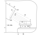
図1及び図2に示す一実施形態の成膜装置1は、孔20を有する基材2を成膜する成膜装置である。成膜装置1は、基材2が収容されるチャンバー3と、チャンバー3内に設けられ、基材2を孔20が上下方向に開口する状態で支える支持部4と、チャンバー3内に設けられ、金属イオン50が発生する蒸発面520を有する蒸発源5とを備える。蒸発源5は、蒸発面520が向く所定方向D1に、基材2の孔20の内周面200の一部が位置するように、所定方向D1が水平方向に対して傾く状態で設置されている。(embodiment)
1. Overview A
また、一実施形態の成膜ユニット10は、孔20を有する基材2が収容されるチャンバー本体30に着脱可能に取り付けられる扉31(32)と、扉31(32)に設けられ、金属イオン50が発生する蒸発面520を有する蒸発源5とを備える。蒸発源5は、蒸発面520が向く所定方向D1が水平方向に対して傾く状態で設置されている。
Further, the
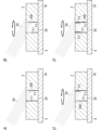
また、図4Aから図4Dに示す一実施形態の成膜方法は、孔20を有する基材2を成膜する成膜方法である。この成膜方法は、配置工程と、ボンバード工程と、成膜工程と、を備える。配置工程は、孔20が上下方向に開口するように、基材2をチャンバー3内に配置する。ボンバード工程は、基材2の孔20の内周面200にイオンを衝突させて、内周面200を洗浄する。成膜工程は、チャンバー3内に設置された蒸発源5から生じた金属イオン50で内周面200を成膜する。蒸発源5は、金属イオン50が生じる蒸発面520を有し、蒸発面520が向く所定方向D1に内周面200の一部が位置するように、所定方向D1が水平方向に対して傾く状態で設置されている。
4A to 4D is a film forming method for forming a film on the
上記構成を備える一実施形態の成膜装置1、成膜ユニット10及び成膜方法では、孔20が上下方向に開口する状態の基材2に対して、孔20の内周面200に金属イオン50を当てることができる。そのため、一実施形態の成膜装置1、成膜ユニット10及び成膜方法では、成膜の過程において、金属イオン50等のイオンとの衝突によって内周面200から剥がれ落ちた酸化膜等の不純物が、内周面200の一部に堆積することを抑制できる。そのうえ、一実施形態の成膜装置1、成膜ユニット10及び成膜方法では、不純物が取り除かれた状態の内周面200に対して、所定方向D1が水平方向に対して傾く状態で設置された蒸発源5から金属イオン50を当てることができる。そのため、一実施形態の成膜装置1、成膜ユニット10及び成膜方法では、内周面200に対して金属イオン50を厚く当てやすくて、金属イオン50で形成される膜を内周面200に密着させやすい。したがって、一実施形態の成膜装置1、成膜ユニット10及び成膜方法では、基材2が有する孔20の内周面200をコーティングする膜の密着性を向上させることができる。
In the
2.詳細
2-1.成膜装置
続いて、一実施形態の成膜装置1について更に詳しく説明する。成膜装置1は、物理的蒸着法(PVD(physical vapor deposition)法)を利用して、基材表面に薄膜を形成する装置である。本実施形態では、成膜装置1は、真空アーク放電により蒸発材料を蒸発させて基材表面を成膜するアークイオンプレーティング法を行う装置である。2. Details 2-1. Film Forming Apparatus Subsequently, the
基材2は、プレス加工に用いられる金型であり、より詳しくは、せん断加工を行うための抜き型である。基材2は、上下方向に開口した孔20を有する。本実施形態では、孔20は、基材2を上下方向に貫通しており、上方と下方の両方に開口している。孔20の内周面200の下部には、下側の部分ほど孔20の開口面積が大きくなるように抜き勾配が付いている。孔20の平面視における形状は、円形、楕円形、多角形等である。
The
成膜装置1は、チャンバー3、支持部4、及び蒸発源5に加えて、バイアス電源6、放電電源7、ガス供給装置(図示せず)、減圧装置(図示せず)、及びヒーター8を備える。
In addition to the
チャンバー3は、図2に示すように、平面視において八角形の形状をした空洞を形成する筐体である。チャンバー3は、減圧装置によって内部を真空状態に減圧することが可能であり、真空状態の内部を気密に保持できる。
The
チャンバー3は、チャンバー本体30と、チャンバー本体30に着脱可能に取り付けられた一対の扉31,32と、を備える。一対の扉31,32は対向している。一対の扉31,32の間にチャンバー本体30が位置する。一対の扉31,32のうち少なくとも一方を開くことで、チャンバー3の内部空間が露出する。
The
本実施形態では、一対の扉31,32のそれぞれは、八角形の8つの辺のうちの連続する3つの辺を構成する3つの側壁310,320を有する。チャンバー本体30は、八角形の8つの辺のうち、対向する2つの辺を構成する二つの側壁300を有する。
In this embodiment, each of the pair of
チャンバー3には、チャンバー3の内部にアルゴン等の不活性ガスを供給するガス供給装置と、チャンバー3の内部の空気を排出してチャンバー3の内部を真空状態まで減圧することができる減圧装置と、が接続されている。ガス供給装置と減圧装置は、例えば、チャンバー本体30の側壁300に接続される。なお、ガス供給装置は、不活性ガスに限らず、成膜に必要な他のガスを供給可能であってもよい。
The
また、チャンバー3内には、チャンバー3の内部を加熱して、基材2の表面の水分等の付着物を蒸発させるヒーター8が設けられている。ヒーター8は、例えば、チャンバー本体30の二つの側壁300のそれぞれに取り付けられている。
A
チャンバー本体30の底部には、ワークテーブル9が設けられている。ワークテーブル9は、平面視円形状の台である。ワークテーブル9は、チャンバー3の底部の略中心を通る鉛直な軸心周りに回転可能なテーブル本体90と、テーブル本体90に回転可能かつ昇降可能に設けられた複数の支持台91と、を有する。
A work table 9 is provided at the bottom of the
複数の支持台91のそれぞれは、平面視円形状の台であり、支持台91の平面視における略中心を通る鉛直な軸心周りに回転可能である。複数の支持台91は、テーブル本体90の軸心の周囲に、テーブル本体90の周方向に等間隔に配置されている。本実施形態では、ワークテーブル9は、6つの支持台91を備えている。ワークテーブル9は、テーブル本体90がその軸心周りに回転しつつ、複数の支持台91のそれぞれがその軸心周りに回転する。なお、テーブル本体90の回転と各支持台91の回転とは連動しなくてもよく、個別に制御されてもよい。
Each of the plurality of support bases 91 is a circular base in plan view, and is rotatable around a vertical axis passing through substantially the center of the
支持台91には、複数の基材2を上下方向に離れた状態で保持する保持具(図示せず)を設置可能である。支持台91に保持具を設置することで、支持台91上には複数の基材2を上下方向に間隔をおいて設置することができる。これにより、複数の基材2のそれぞれを、テーブル本体90の軸心周りに回転させるとともに、各支持台91の軸心周りに回転させることができる。
A holder (not shown) that holds the plurality of
本実施形態では、図1に示すように、各支持台91は、テーブル本体90に対して昇降可能に設けられている。各支持台91は、例えば、利用者が制御装置を制御することによって、支持台91に載せた基材2が蒸発源5の蒸発面520に対向する(正対する)ように、各支持台91の上下位置が調整される。なお、支持台91の高さは、制御装置によって自動的に調整されてもよい。
In this embodiment, as shown in FIG. 1, each
本実施形態では、支持部4は、支持台91である。なお、支持部4は、支持台91に設置される保持具であってもよいし、テーブル本体90であってもよい。
In this embodiment, the
ワークテーブル9には、ワークテーブル9に負の電圧を印加するバイアス電源6が接続されている。バイアス電源6がワークテーブル9に負の電圧を印加することで、ワークテーブル9の支持台91に支持された基材2に、負の電圧が印加される。
A
蒸発源5は、チャンバー3内に設けられる。蒸発源5は、金属イオン50が発生する蒸発面520を有する。蒸発源5は、蒸発面520が向く所定方向D1に、基材2の孔20の内周面200の一部が位置するように、所定方向D1が水平方向に対して傾く状態で設置されている。
An
より詳しくは、蒸発源5は、筐体51と、筐体51に着脱可能に装着される蒸発材料52と、を有する。筐体51は、蒸発材料52が装着される取付面510を有する。取付面510は、支持部4に支持された基材2に対向する(正対する)面である。筐体51は、取付面510が支持部4に支持された基材2に向くように、チャンバー3の側壁に取り付けられている。本実施形態では、取付面510は、斜め下方を向いている。
More specifically, the
蒸発材料52は、円板等の板状の部材である。蒸発材料52は、厚み方向の片側に、金属イオン50が発生する蒸発面520を有する。蒸発面520が向く所定方向D1とは、蒸発材料52の厚み方向のうち、蒸発面520が向く方向を意味する。蒸発面520が向く所定方向D1と、筐体51の取付面510が向く方向とは同じである。
The
蒸発源5には、蒸発材料52の蒸発面520にアーク放電を生じさせる放電電源7が接続されている。蒸発源5には、放電電源7の正極が接続されている。放電電源7から蒸発源5に正の電圧が印加され、蒸発面520にアーク放電が生じることで、蒸発材料52が溶解、蒸発して、蒸発面520から金属イオン50の蒸気が発生する。
A
本実施形態では、成膜装置1は、図1及び図2に示すように、複数(詳しくは8つ)の蒸発源5を備える。蒸発源5は、チャンバー3の一対の扉31,32のそれぞれに取り付けられており、チャンバー本体30には取り付けられていない。蒸発源5は、一対の扉31,32の三つの側壁310,320のうち、中間に位置する側壁310a,320aを除いた残りの二つの側壁310b,320bのそれぞれに、上下方向に間隔をおいて二つずつ取り付けられている。
In this embodiment, the
本実施形態では、各蒸発源5は、蒸発面520が向く所定方向D1が水平方向に対して15~30度の角度をなすように設置されており、蒸発面520が斜め下方を向いている。蒸発面520に対向する位置に、支持部4に支持された基材2が設置される。なお、各蒸発源5の設置角度は、適宜設定可能である。
In this embodiment, each
2-2.成膜ユニット
続いて、一実施形態の成膜ユニット10について更に詳しく説明する。成膜ユニット10は、上述した成膜装置1の一部を構成する。2-2. Film Forming Unit Next, the
成膜ユニット10は、チャンバー本体30に着脱可能に取り付けられる扉31(32)と、扉31(32)に設けられ、金属イオン50が発生する蒸発面520を有する蒸発源5とを備える。蒸発源5は、蒸発面520が向く所定方向D1が水平方向に対して傾く状態で設置されている。
The
本実施形態の成膜装置1は、二つの成膜ユニット10を備えている。二つの成膜ユニット10のうちの一方が扉31を有し、他方が扉32を有する。
The
一方の成膜ユニット10は、扉31の二つの側壁310bのうちの一方の端部がチャンバー本体30の側壁300に、ヒンジを介して回転可能に接続されている。また、他方の成膜ユニット10は、扉32の二つの側壁320bのうちの一方がチャンバー本体30の側壁300に、ヒンジを介して回転可能に接続されている。二つの成膜ユニット10のそれぞれは、チャンバー本体30に対して着脱可能である。
One
成膜ユニット10は、既設のチャンバー3の一対の扉の交換部品としても利用可能である。また、成膜ユニット10は、単体で販売可能である。
The
2-3.成膜方法
続いて、上述した成膜装置1を用いて基材2の孔20の内周面200を成膜する成膜方法について詳しく説明する。2-3. Film Forming Method Subsequently, a film forming method for forming a film on the inner
成膜方法は、配置工程、減圧工程、加熱工程、ボンバード工程、及び成膜工程を備える。 The film formation method includes an arrangement process, a decompression process, a heating process, a bombardment process, and a film formation process.
配置工程では、孔20が上下方向に開口するように、基材2をチャンバー3内に配置する。本実施形態の配置工程では、まず、チャンバー3の一対の扉31,32のうちの少なくとも一方を開いた後、ワークテーブル9の複数の支持台91のうちの少なくとも一つの支持台91の上に、孔20が上方に向けて開口するように、基材2を載せる。基材2を支持台91の上に載せたら、一対の扉31,32を閉じて、チャンバー3の内部空間を密閉状態とする。
In the placement step, the
減圧工程では、減圧装置を用いてチャンバー3の内部の空気を排出し、チャンバー3の内部を真空状態とする。その後、ガス供給装置を用いてチャンバー3の内部にアルゴンガス等の不活性ガスや成膜に必要なガスを供給する。
In the decompression step, the air inside the
加熱工程では、ヒーター8によりチャンバー3の内部を加熱し、基材2の表面に付着している水分等の不純物を蒸発させる。
In the heating step, the interior of the
ボンバード工程では、基材2の孔20の内周面200にイオンを衝突させて、内周面200を洗浄する。成膜工程では、チャンバー3内に設置された蒸発源5から生じた金属イオン50で内周面200を成膜する。ここで、蒸発源5は、金属イオン50が生じる蒸発面520を有し、蒸発面520が向く所定方向D1に内周面200の一部が位置するように、所定方向D1が水平方向に対して傾く状態で設置されている。
In the bombarding process, the inner
本実施形態のボンバード工程は、蒸発源5から生じる金属イオン50を基材2の孔20の内周面200に衝突させることで、内周面200を洗浄する工程である。
The bombarding step of the present embodiment is a step of cleaning the inner
より詳しくは、本実施形態のボンバード工程及び成膜工程では、図3に示すように、蒸発源5の蒸発面520に対向する(正対する)位置に、基材2の孔20の内周面200の一部が位置するように、支持台91の上下位置を調整する。次いで、蒸発源5に放電電源7から正の電圧を印加し、蒸発材料52の蒸発面520にアーク放電を生じさせることで、蒸発面520から金属イオン50の蒸気を生じさせる。次いで、バイアス電源6からワークテーブル9に負の電圧を印加し、基材2に負の電圧を印加する。これにより、蒸発源5の蒸発材料52の蒸発面520から蒸発した金属イオン50が基材2に向けて高速で移動し、金属イオン50が基材2の孔20の内周面200の一部(詳しくは、内周面200のうち、蒸発面520に対向する(正対する)部分)に衝突する。
More specifically, in the bombardment process and film formation process of the present embodiment, as shown in FIG. The vertical position of the
ボンバード工程及び成膜工程では、ワークテーブル9のテーブル本体90と基材2を載せた支持台91とをそれぞれ回転させて、基材2を回転させる。これにより、基材2の孔20の内周面200のうち、蒸発源5から照射される金属イオン50の衝突する部分が変化して、基材2の孔20の内周面200の上部(例えば孔20の上端から5~10mmの範囲)が周方向の全長にわたって、金属イオン50が衝突する。
In the bombardment process and the film formation process, the
蒸発源5から発生した金属イオン50が基材2の孔20の内周面200に衝突する工程のうちの初期段階がボンバード工程であり、初期段階以降の段階が成膜工程である。本実施形態のボンバード工程では、蒸発源5から発生した金属イオン50が内周面200に衝突することで、内周面200に付着した酸化膜等の不純物が剥ぎ落とされる。つまり、本実施形態のボンバード工程では、基材2の表面に金属イオン50を衝突させて洗浄を行うメタルイオンボンバードが行われる。ここで、基材2の孔20の内周面200の下部は、孔20の開口面積が下側ほど広くなるように抜き勾配が付いているため、内周面200の一部から剥がれ落ちた不純物は、内周面200の他の一部に堆積せず、支持台91上に落下する。
The initial stage of the process in which the
本実施形態のボンバード工程では、回転する基材2の孔20の内周面200の上部に金属イオン50が衝突することで、図4A、図4Bに示すように、内周面200の上部の酸化膜等の不純物F1が内周面200の周方向の全長にわたって剥がれ落ちる。
In the bombarding process of the present embodiment, the
本実施形態の成膜工程では、回転する基材2の孔20の不純物F1が除去された内周面200の上部に金属イオン50が衝突することで、図4C、図4Dに示すように、内周面200の上部が周方向の全長にわたって金属イオン50で成膜される(言い換えると金属イオン50の膜F2が形成される)。なお、図4Aから図4Dでは、不純物F1及び膜F2について、模式的に図示している。
In the film forming process of the present embodiment,
内周面200のうち上部を除く残りの部分は、蒸発面520に対向(正対)していないため、金属イオン50が衝突しにくく、不純物F1の除去や金属イオン50による成膜が行われにくい。
Since the remaining portion of the inner
また、本実施形態の成膜方法によれば、蒸発面520から発生した金属イオン50が、基材2の孔20の内周面200だけでなく、基材2の上面及び外周面にも衝突するため、基材2の上面及び外周面に対してもボンバード工程と成膜工程を行うことができる。
Further, according to the film forming method of the present embodiment, the
3.作用効果
以上説明した本実施形態の成膜装置1、成膜ユニット10及び成膜方法では、孔20が上下方向に開口する状態の基材2に対して、孔20の内周面200に金属イオン50を当てることができる。そのため、成膜の一工程(詳しくはボンバード工程)において、イオン(金属イオン50)との衝突によって内周面200から剥がれ落ちた不純物が、内周面200の一部に堆積することを抑制できる。そのうえ、本実施形態の成膜装置1では、不純物が取り除かれた状態の内周面200に対して、所定方向D1が水平方向に対して傾く状態で設置された蒸発源5から金属イオン50を当てることができる。そのため、本実施形態の成膜装置1では、内周面200に対して金属イオン50を厚く当てやすくて、金属イオン50で形成される膜を内周面200に密着させやすい。したがって、本実施形態の成膜装置1では、基材2が有する孔20の内周面200をコーティングする膜の密着性を向上させることができる。3. Effects In the
また、本実施形態の成膜装置1、成膜ユニット10、及び成膜方法では、基材2を支持する支持部4(支持台91)の上下位置の調整が可能であるため、蒸発源5の蒸発面520に対向(正対)した位置に、基材2の孔20の内周面200を配置しやすい。そのため、本実施形態の成膜装置1、成膜ユニット10、及び成膜方法では、基材2の孔20の内周面200に対して、蒸発源5の蒸発面520で発生した金属イオン50を衝突させやすく、ボンバード工程及び成膜工程が効率良く行える。これにより、ボンバード工程及び成膜工程に必要な蒸発材料52の量を抑えることができる。
In addition, in the
また、本実施形態の成膜装置1、成膜ユニット10、及び成膜方法では、支持台91が回転可能であるため、基材2が回転可能であり、蒸発源5で発生した金属イオン50を、基材2の孔20の内周面200に対して周方向の全長にわたって衝突させることができる。そのため、本実施形態の成膜装置1、成膜ユニット10、及び成膜方法では、基材2の孔20の内周面200をコーティングする金属イオン50の膜厚を、内周面200の周方向の全長にわたって一定としやすく、膜の密着性が安定しやすい。
Further, in the
また、本実施形態の成膜装置1、成膜ユニット10、及び成膜方法では、基材2の孔20の内周面200のうち上部のみ金属イオン50の膜が形成される。本実施形態では、基材2はプレス加工用の抜き型であるため、孔20の内周面200の上部をコーティングする膜の密着性が重要であり、孔20の内周面200の下部への膜の形成は不要である。
Further, in the
4.変形例
続いて、上述した成膜装置1及び成膜方法の変形例について説明する。以下に説明する各変形例は適宜組み合わせ可能である。4. Modification Next, a modification of the
成膜装置1は、物理的蒸着法(PVD法)を利用して、基材2の表面に薄膜を形成する装置であればよく、アークイオンプレーティング法以外の方法によって成膜を行う装置であってもよい。
The
成膜装置1は、蒸発源5とは別にボンバード工程を行うボンバード装置を備えてもよい。ボンバード装置は、例えば、チャンバー3の内部空間にグロー放電を生じさせることで、不活性ガスをイオン化するカソード(陰電極)とアノード(陽電極)を有する。この場合、ボンバード装置によって不活性ガスのイオンを生じさせた状態で、バイアス電源6からワークテーブル9に負の電圧を印加し、基材2に負の電圧を印加することで、不活性ガスのイオンを基材2の内周面200に衝突させて、内周面200を洗浄する。不活性ガスのイオンによる内周面200の洗浄が終わった後、蒸発源5によって内周面200に金属イオン50による成膜を行う。
The
成膜装置1は、蒸発源5の蒸発面520が向く所定方向D1に、基材2の孔20の内周面200の一部が位置するように、所定方向D1が水平方向に対して傾く状態で設置されたものであればよく、図1、2に示す構造に限定されない。例えば、成膜装置1は、バイアス電源6及び放電電源7を備えなくてもよい。成膜装置1は、アーク放電以外の方法で、蒸発面520から金属イオン50を発生させるものであってもよい。また、成膜装置1は、バイアス電源6で基材2に負の電圧を印加する方法以外の方法で、蒸発面520から基材2へと金属イオン50を向かわせるものであってもよい。
In the
支持部4は、鉛直方向に対して平行な軸周りに回転可能でなくてもよい。この場合、例えば、蒸発源5を、支持部4(基材2)の周囲を円軌道で移動するように設ければよい。
The
また、支持部4は、上下方向の位置が変更可能でなくてもよい。この場合、例えば、蒸発源5を、上下方向に移動可能に設ければよい。
Further, the
また、蒸発源5は、図5に示す変形例のように、蒸発面520が向く所定方向D1が変更可能であってもよい。所定方向D1は、例えば、水平方向に対して-30度から+30度の範囲で変更可能である。この場合、例えば、蒸発源5は、角度の調整可能な支持機構を介してチャンバー3の側壁に取り付けられれる。支持機構による蒸発源5の角度調整は、例えば、利用者が制御装置を操作することで、自動的に行える。なお、支持機構は、利用者が手動で操作してもよい。
Moreover, the
また、成膜装置1は、扉31(32)に蒸発源5が取り付けられたものに限らず、チャンバー本体30に蒸発源5が取り付けられたものであってもよい。
Moreover, the
また、成膜装置1は、蒸発面520が向く所定方向D1が、水平方向に対して傾く状態に設置された蒸発源5に加えて、蒸発面520が水平方向を向く従来の蒸発源5を備えてもよい。
In addition to the
また、成膜装置1は、上下に並ぶ二つの蒸発源5のうち、上側の蒸発源5を蒸発面520が斜め下方を向くように設置し、下側の蒸発源5を蒸発面520が斜め上方を向くように設置してもよい。この場合、支持台91に設置した保持部材によって保持された基材2の孔20の内周面200に対して、斜め上方と斜め下方の両方から金属イオン50を衝突させることができて、内周面200を上下方向にわたって成膜することができる。また、成膜装置1は、複数の蒸発源5の全てが、蒸発面520が斜め上方を向くように設置してもよい。
In the
5.まとめ
以上説明した実施形態及びその変形例のように、第一態様の成膜装置(1)は、下記の構成を備える。5. Summary Like the embodiment and its modification described above, the film forming apparatus (1) of the first mode has the following configuration.
すなわち、第一態様の成膜装置(1)は、孔(20)を有する基材(2)を成膜する成膜装置である。成膜装置(1)は、基材(2)が収容されるチャンバー(3)と、チャンバー(3)内に設けられ、基材(2)を孔(20)が上下方向に開口する状態で支える支持部(4)と、チャンバー(3)内に設けられ、金属イオン(50)が発生する蒸発面(520)を有する蒸発源(5)とを備える。蒸発源(5)は、蒸発面(520)が向く所定方向(D1)に、基材(2)の孔(20)の内周面(200)の一部が位置するように、水平方向に対して所定方向(D1)が傾く状態で設置されている。 That is, the film forming apparatus (1) of the first aspect is a film forming apparatus for forming a film on the substrate (2) having the holes (20). A film forming apparatus (1) is provided in a chamber (3) in which a substrate (2) is accommodated, and the substrate (2) is provided in a state in which holes (20) are opened vertically. It comprises a supporting support (4) and an evaporation source (5) provided in the chamber (3) and having an evaporation surface (520) on which metal ions (50) are generated. The evaporation source (5) is horizontally positioned so that a part of the inner peripheral surface (200) of the hole (20) of the substrate (2) is positioned in the predetermined direction (D1) in which the evaporation surface (520) faces. It is installed in a state in which the predetermined direction (D1) is inclined.
上記構成を備える第一態様の成膜装置(1)では、孔(20)が上下方向に開口する状態の基材(2)に対して、孔(20)の内周面(200)に金属イオン(50)を当てることができる。そのため、第一態様の成膜装置(1)では、成膜の過程において、金属イオン(50)等のイオンとの衝突によって内周面(200)から剥がれ落ちた酸化膜等の不純物が、内周面(200)の一部に堆積することを抑制できる。そのうえ、第一態様の成膜装置(1)では、不純物が取り除かれた状態の内周面(200)に対して、水平方向に対して所定方向(D1)が傾く状態で設置された蒸発源(5)から金属イオン(50)を当てることができる。そのため、第一態様の成膜装置(1)では、内周面(200)に対して金属イオン(50)を厚く当てやすくて、金属イオン(50)で形成される膜を内周面(200)に密着させやすい。したがって、第一態様の成膜装置(1)では、基材(2)が有する孔(20)の内周面(200)をコーティングする膜の密着性を向上させることができる。 In the film forming apparatus (1) of the first aspect having the above configuration, metal is applied to the inner peripheral surface (200) of the hole (20) with respect to the substrate (2) in which the hole (20) opens vertically. Ions (50) can be applied. Therefore, in the film-forming apparatus (1) of the first aspect, impurities such as oxide films peeled off from the inner peripheral surface (200) due to collisions with ions such as metal ions (50) during the film-forming process are Deposition on a part of the peripheral surface (200) can be suppressed. Moreover, in the film forming apparatus (1) of the first aspect, the evaporation source is installed such that the predetermined direction (D1) is inclined with respect to the horizontal direction with respect to the inner peripheral surface (200) from which impurities have been removed. Metal ions (50) can be applied from (5). Therefore, in the film forming apparatus (1) of the first aspect, it is easy to apply the metal ions (50) thickly to the inner peripheral surface (200), and the film formed of the metal ions (50) is formed on the inner peripheral surface (200). ). Therefore, in the film forming apparatus (1) of the first aspect, it is possible to improve the adhesion of the film that coats the inner peripheral surface (200) of the hole (20) of the substrate (2).
また、上述した実施形態及びその変形例のように、第二態様の成膜装置(1)は、第一態様の構成に加えて、下記の構成を付加的に備える。 Moreover, like the embodiment and its modification described above, the film forming apparatus (1) of the second aspect additionally includes the following configuration in addition to the configuration of the first aspect.
すなわち、第二態様の成膜装置(1)は、支持部(4)に負の電圧を印加することで、基材(2)に負の電圧を印加するバイアス電源(6)と、蒸発源(5)に正の電圧を印加することで、蒸発面(520)にアーク放電を生じさせて金属イオン(50)を発生させる放電電源(7)と、を更に備える。 That is, the film forming apparatus (1) of the second aspect includes a bias power supply (6) that applies a negative voltage to the substrate (2) by applying a negative voltage to the support (4), and an evaporation source A discharge power source (7) for generating an arc discharge on the evaporation surface (520) to generate metal ions (50) by applying a positive voltage to (5).
上記構成を備える第二態様の成膜装置(1)では、蒸発面(520)から発生した金属イオン(50)が基材(2)に向かって高速で移動しやすく、基材(2)の孔(20)の内周面(200)に金属イオン(50)を衝突させやすくて、内周面(200)に金属イオン(50)の膜を形成しやすい。 In the film forming apparatus (1) of the second aspect having the above configuration, the metal ions (50) generated from the evaporation surface (520) easily move toward the substrate (2) at high speed, and the substrate (2) Metal ions (50) can easily collide with the inner peripheral surface (200) of the hole (20), and a film of metal ions (50) can be easily formed on the inner peripheral surface (200).
また、上述した実施形態及びその変形例のように、第三態様の成膜装置(1)は、第二態様の構成に加えて、下記の構成を付加的に備える。 Moreover, like the embodiment and its modification described above, the film forming apparatus (1) of the third aspect additionally includes the following configuration in addition to the configuration of the second aspect.
すなわち、第三態様の成膜装置(1)では、蒸発源(5)は、ボンバード工程と、成膜工程とを行う。ボンバード工程では、基材(2)の孔(20)の内周面(200)の一部に金属イオン(50)を衝突させて、内周面(200)の一部の洗浄を行う。成膜工程では、洗浄後の内周面(200)の一部に金属イオン(50)を衝突させて、金属イオン(50)で内周面(200)を成膜する。 That is, in the film forming apparatus (1) of the third aspect, the evaporation source (5) performs the bombardment process and the film forming process. In the bombardment process, metal ions (50) are made to collide with a part of the inner peripheral surface (200) of the hole (20) of the base material (2) to wash a part of the inner peripheral surface (200). In the film-forming step, metal ions (50) are made to collide with a part of the inner peripheral surface (200) after cleaning, and the inner peripheral surface (200) is formed with the metal ions (50).
上記構成を備える第三態様の成膜装置(1)では、基材(2)の孔(20)の内周面(200)に金属イオン(50)を厚く衝突させやすいため、内周面(200)に付着した酸化膜等の不純物を除去しやすい。また、第三態様の成膜装置(1)では、蒸発源(5)とは別にボンバード工程を行うための装置を備える必要がないため、構造の簡素化が図れる。 In the film forming apparatus (1) of the third aspect having the above configuration, the metal ions (50) are likely to collide thickly with the inner peripheral surface (200) of the holes (20) of the substrate (2), so the inner peripheral surface ( 200), it is easy to remove impurities such as an oxide film adhering to the substrate. Further, in the film forming apparatus (1) of the third aspect, since it is not necessary to provide a device for performing the bombardment process separately from the evaporation source (5), the structure can be simplified.
また、上述した実施形態及びその変形例のように、第四態様の成膜装置(1)は、第一から第三のいずれか一つの態様の構成に加えて、下記の構成を付加的に備える。 Further, as in the above-described embodiments and modifications thereof, the film deposition apparatus (1) of the fourth aspect additionally has the following configuration in addition to the configuration of any one of the first to third aspects. Prepare.
すなわち、第四態様の成膜装置(1)では、支持部(4)は、鉛直方向に対して平行な軸周りに回転可能である。 That is, in the film forming apparatus (1) of the fourth aspect, the supporting section (4) is rotatable around an axis parallel to the vertical direction.
上記構成を備える第四態様の成膜装置(1)では、支持部(4)に支持された基材(2)を鉛直方向に対して平行な軸周りに回転させることができるため、基材(2)の孔(20)の内周面(200)の周方向の全長に金属イオン(50)を当てやすい。そのため、第四態様の成膜装置(1)では、基材(2)の孔(20)の内周面(200)に形成される金属イオン(50)の膜厚が、内周面(200)の周方向の全長にわたって安定しやすい。 In the film forming apparatus (1) of the fourth aspect having the above configuration, the substrate (2) supported by the supporting portion (4) can be rotated around an axis parallel to the vertical direction. (2) It is easy to apply metal ions (50) to the entire circumferential length of the inner peripheral surface (200) of the hole (20). Therefore, in the film forming apparatus (1) of the fourth aspect, the film thickness of the metal ions (50) formed on the inner peripheral surface (200) of the hole (20) of the substrate (2) is ) is easily stabilized over the entire circumferential length.
また、上述した実施形態及びその変形例のように、第五態様の成膜装置(1)は、第一から第四のいずれか一つの態様の構成に加えて、下記の構成を付加的に備える。 Further, as in the above-described embodiments and modifications thereof, the film deposition apparatus (1) of the fifth aspect additionally has the following configuration in addition to the configuration of any one of the first to fourth aspects. Prepare.
すなわち、第五態様の成膜装置(1)では、支持部(4)は、上下方向の位置を変更可能である。 That is, in the film forming apparatus (1) of the fifth aspect, the support portion (4) can change its position in the vertical direction.
上記構成を備える第五態様の成膜装置(1)では、支持部(4)に支持された基材(2)の上下方向の位置を変更することができるため、蒸発源(5)の蒸発面(520)に対向(正対)する位置へ基材(2)の孔(20)の内周面(200)を配置しやすくて、金属イオン(50)を内周面(200)に当てやすい。 In the film forming apparatus (1) of the fifth aspect having the above configuration, since the vertical position of the substrate (2) supported by the supporting part (4) can be changed, evaporation of the evaporation source (5) It is easy to arrange the inner peripheral surface (200) of the hole (20) of the substrate (2) at a position facing (directly facing) the surface (520), and the metal ions (50) are applied to the inner peripheral surface (200). Cheap.
また、上述した実施形態の変形例のように、第六態様の成膜装置(1)は、第一から第五のいずれか一つの態様の構成に加えて、下記の構成を付加的に備える。 Further, like the modification of the embodiment described above, the film deposition apparatus (1) of the sixth aspect additionally includes the following configuration in addition to the configuration of any one of the first to fifth aspects. .
すなわち、第六態様の成膜装置(1)では、蒸発源(5)は、蒸発面(520)が向く所定方向(D1)が変更可能である。 That is, in the film forming apparatus (1) of the sixth aspect, the predetermined direction (D1) in which the evaporation surface (520) of the evaporation source (5) faces can be changed.
上記構成を備える第六態様の成膜装置(1)では、蒸発面(520)が向く所定方向(D1)を、基材(2)の孔(20)の内周面(200)の位置に合わせて適切な方向に変更することができるため、金属イオン(50)を内周面(200)に当てやすい。 In the film forming apparatus (1) of the sixth aspect having the above configuration, the predetermined direction (D1) in which the evaporation surface (520) faces is aligned with the inner peripheral surface (200) of the hole (20) of the substrate (2). Since it can be changed to an appropriate direction, it is easy to apply the metal ions (50) to the inner peripheral surface (200).
また、上述した実施形態の変形例のように、第七態様の成膜装置(1)は、第一から第六のいずれか一つの態様の構成に加えて、下記の構成を付加的に備える。 Further, like the modified example of the embodiment described above, the film forming apparatus (1) of the seventh aspect additionally includes the following configuration in addition to the configuration of any one of the first to sixth aspects. .
すなわち、第七態様の成膜装置(1)では、チャンバー(3)は、チャンバー本体(30)と、チャンバー本体(30)に着脱可能に取り付けられた扉(31,32)と、を有する。蒸発源(5)は、扉(31,32)に取り付けられている。 That is, in the film forming apparatus (1) of the seventh aspect, the chamber (3) has a chamber body (30) and doors (31, 32) detachably attached to the chamber body (30). The evaporation source (5) is attached to the doors (31, 32).
上記構成を備える第七態様の成膜装置(1)では、蒸発源(5)が取り付けられた扉(31,32)をチャンバー本体(30)から取り外すことができるため、蒸発源(5)のメンテナンスや蒸発源(5)の取付角度を変更する作業が行いやすい。 In the film forming apparatus (1) of the seventh aspect having the above configuration, the doors (31, 32) to which the evaporation source (5) is attached can be removed from the chamber main body (30). It is easy to perform maintenance and work to change the mounting angle of the evaporation source (5).
また、上述した実施形態及びその変形例のように、第八態様の成膜ユニット(10)は、下記の構成を備える。 Moreover, like the above-described embodiment and its modifications, the film forming unit (10) of the eighth mode has the following configuration.
すなわち、第八態様の成膜ユニット(10)は、孔(20)を有する基材(2)が収容されるチャンバー本体(30)に着脱可能に取り付けられる扉(31,32)と、扉(31,32)に設けられ、金属イオン(50)が発生する蒸発面(520)を有する蒸発源(5)とを備える。蒸発源(5)は、蒸発面(520)が向く所定方向(D1)が水平方向に対して傾く状態で設置されている。 That is, the film forming unit (10) of the eighth aspect includes doors (31, 32) detachably attached to a chamber body (30) in which a substrate (2) having holes (20) is accommodated, and a door ( 31, 32) and an evaporation source (5) having an evaporation surface (520) on which metal ions (50) are generated. The evaporation source (5) is installed such that the predetermined direction (D1) in which the evaporation surface (520) faces is inclined with respect to the horizontal direction.
上記構成を備える第八態様の成膜ユニット(10)では、チャンバー本体(30)に対して着脱可能であるため、例えば既設の成膜装置の扉の交換用部品として利用することができて、汎用性が高い。 Since the film forming unit (10) of the eighth aspect having the above configuration is detachable from the chamber body (30), it can be used as a replacement part for the door of an existing film forming apparatus, for example. Highly versatile.
また、上述した実施形態及びその変形例のように、第九態様の成膜方法は、下記の構成を備える。 Moreover, like the above-described embodiment and its modification, the film forming method of the ninth aspect has the following configuration.
すなわち、第九態様の成膜方法は、孔(20)を有する基材(2)を成膜する成膜方法である。第九態様の成膜方法は、配置工程と、ボンバード工程と、成膜工程とを備える。配置工程では、孔(20)が上下方向に開口するように、基材(2)をチャンバー(3)内に配置する。ボンバード工程では、基材(2)の孔(20)の内周面(200)にイオンを衝突させて、内周面(200)を洗浄する。成膜工程では、チャンバー(3)内に設置された蒸発源(5)から生じた金属イオン(50)で内周面(200)を成膜する。蒸発源(5)は、金属イオン(50)が生じる蒸発面(520)を有し、蒸発面(520)が向く所定方向(D1)に内周面(200)の一部が位置するように、水平方向に対して所定方向(D1)が傾く状態で設置されている。 That is, the film forming method of the ninth aspect is a film forming method for forming a film on the substrate (2) having the holes (20). The film formation method of the ninth aspect includes an arrangement step, a bombardment step, and a film formation step. In the placement step, the substrate (2) is placed in the chamber (3) so that the holes (20) open vertically. In the bombarding process, the inner peripheral surface (200) of the holes (20) of the substrate (2) is bombarded with ions to wash the inner peripheral surface (200). In the film forming process, the inner peripheral surface (200) is formed with metal ions (50) generated from the evaporation source (5) installed in the chamber (3). The evaporation source (5) has an evaporation surface (520) on which metal ions (50) are generated, and a part of the inner peripheral surface (200) is positioned in a predetermined direction (D1) in which the evaporation surface (520) faces. , is installed in a state in which a predetermined direction (D1) is inclined with respect to the horizontal direction.
上記構成を備える第九態様の成膜方法では、孔(20)が上下方向に開口する状態の基材(2)に対して、孔(20)の内周面(200)にイオンを衝突させることができる。そのため、第九態様の成膜方法では、ボンバード工程において、イオンとの衝突によって内周面(200)から剥がれ落ちた不純物が、内周面(200)の一部に堆積することを抑制できる。そのうえ、第九態様の成膜方法では、不純物が取り除かれた状態の内周面(200)に対して、水平方向に対して所定方向(D1)が傾く状態で設置された蒸発源(5)から金属イオン(50)を当てることができる。そのため、第九態様の成膜方法では、内周面(200)に対して金属イオン(50)を厚く当てやすくて、金属イオン(50)で形成される膜を内周面(200)に密着させやすい。したがって、第九態様の成膜方法では、基材(2)が有する孔(20)の内周面(200)をコーティングする膜の密着性を向上させることができる。 In the film formation method of the ninth aspect having the above configuration, ions are caused to collide with the inner peripheral surface (200) of the holes (20) of the substrate (2) in which the holes (20) are open in the vertical direction. be able to. Therefore, in the film forming method of the ninth aspect, it is possible to suppress deposition of impurities that have fallen off the inner peripheral surface (200) due to collisions with ions in the bombarding process. Moreover, in the film formation method of the ninth aspect, the evaporation source (5) is installed in a state in which the predetermined direction (D1) is inclined with respect to the horizontal direction with respect to the inner peripheral surface (200) from which impurities have been removed. metal ions (50) can be applied from. Therefore, in the film forming method of the ninth aspect, it is easy to apply the metal ions (50) thickly to the inner peripheral surface (200), and the film formed of the metal ions (50) is adhered to the inner peripheral surface (200). easy to let Therefore, in the film forming method of the ninth aspect, it is possible to improve the adhesion of the film that coats the inner peripheral surface (200) of the hole (20) of the substrate (2).
また、上述した実施形態及びその変形例のように、第十態様の成膜方法は、第九態様の構成に加えて、下記の構成を付加的に備える。 Moreover, like the above-described embodiment and its modification, the film forming method of the tenth aspect additionally includes the following configuration in addition to the configuration of the ninth aspect.
すなわち、第十態様の成膜方法では、ボンバード工程は、蒸発源(5)から生じる金属イオン(50)を基材(2)の孔(20)の内周面(200)に衝突させることで、内周面(200)を洗浄する工程である。 That is, in the film formation method of the tenth aspect, the bombardment step is to collide the metal ions (50) generated from the evaporation source (5) with the inner peripheral surface (200) of the holes (20) of the substrate (2). , cleaning the inner peripheral surface (200).
上記構成を備える第十態様の成膜方法では、基材(2)の孔(20)の内周面(200)に金属イオン(50)を厚く衝突させやすいため、内周面(200)に付着した酸化膜等の不純物を除去しやすい。また、第十態様の成膜方法では、蒸発源(5)とは別にボンバード工程を行うための装置を備える必要がないため、成膜方法を実施する成膜装置(1)の構造の簡素化が図れる。 In the film forming method of the tenth aspect having the above configuration, since the metal ions (50) are likely to collide thickly with the inner peripheral surface (200) of the hole (20) of the substrate (2), the inner peripheral surface (200) Impurities such as adhering oxide films are easily removed. Further, in the film formation method of the tenth aspect, since it is not necessary to provide an apparatus for performing the bombardment process separately from the evaporation source (5), the structure of the film formation apparatus (1) for carrying out the film formation method is simplified. can be achieved.
以上、本開示を添付図面に示す実施形態に基づいて説明したが、本開示は上記の実施形態に限定されるものではなく、本開示の意図する範囲内であれば、適宜の設計変更が可能である。 As described above, the present disclosure has been described based on the embodiments shown in the accompanying drawings, but the present disclosure is not limited to the above embodiments, and appropriate design changes are possible within the scope intended by the present disclosure. is.
1 成膜装置
2 基材
20 孔
200 内周面
3 チャンバー
30 チャンバー本体
31 扉
32 扉
4 支持部
5 蒸発源
50 金属イオン
52 蒸発材料
520 蒸発面
6 バイアス電源
7 放電電源
10 成膜ユニット
D1 所定方向1
Claims (10)
前記金型が収容されるチャンバーと、
前記チャンバー内に設けられ、前記金型を前記孔が上下方向に開口する状態で支える支持部と、
前記チャンバー内に設けられ、金属イオンが発生する蒸発面を有する蒸発源とを備え、
前記蒸発源は、前記蒸発面が向く所定方向に、前記金型の前記孔の内周面の一部が位置するように、前記所定方向が水平方向に対して傾く状態で設置されている、
ことを特徴とする成膜装置。 A film forming apparatus for forming a film on a mold having a hole for performing shearing,
a chamber in which the mold is housed;
a support part provided in the chamber and supporting the mold with the hole open in the vertical direction;
an evaporation source provided in the chamber and having an evaporation surface on which metal ions are generated;
The evaporation source is installed in a state in which the predetermined direction is inclined with respect to the horizontal direction so that a part of the inner peripheral surface of the hole of the mold is positioned in the predetermined direction in which the evaporation surface faces.
A film forming apparatus characterized by:
前記蒸発源に正の電圧を印加することで、前記蒸発面にアーク放電を生じさせて前記金属イオンを発生させる放電電源と、を更に備える、
ことを特徴とする請求項1に記載の成膜装置。 a bias power supply that applies a negative voltage to the mold by applying a negative voltage to the support;
a discharge power source that applies a positive voltage to the evaporation source to cause an arc discharge on the evaporation surface to generate the metal ions;
The film forming apparatus according to claim 1, characterized in that:
前記金型の前記孔の前記内周面の前記一部に前記金属イオンを衝突させて、前記内周面の前記一部の洗浄を行うボンバード工程と、洗浄後の前記内周面の前記一部に前記金属イオンを衝突させて、前記金属イオンで前記内周面を成膜する成膜工程とを行う、
ことを特徴とする請求項2に記載の成膜装置。 The evaporation source is
a bombarding step of colliding the metal ions with the part of the inner peripheral surface of the hole of the mold to clean the part of the inner peripheral surface; a film forming step of colliding the metal ions with the part and forming a film on the inner peripheral surface with the metal ions;
3. The film forming apparatus according to claim 2, characterized in that:
ことを特徴とする請求項1から3のいずれか一項に記載の成膜装置。 The support is rotatable around an axis parallel to the vertical direction,
The film forming apparatus according to any one of claims 1 to 3, characterized in that:
ことを特徴とする請求項1から4のいずれか一項に記載の成膜装置。 The support part can change the position in the vertical direction,
The film forming apparatus according to any one of claims 1 to 4, characterized in that:
ことを特徴とする請求項1から5のいずれか一項に記載の成膜装置。 In the evaporation source, the predetermined direction in which the evaporation surface faces can be changed.
The film forming apparatus according to any one of claims 1 to 5, characterized in that:
前記蒸発源は、前記扉に取り付けられている、
ことを特徴とする請求項1から6のいずれか一項に記載の成膜装置。 The chamber has a chamber body and a door detachably attached to the chamber body,
The evaporation source is attached to the door,
The film forming apparatus according to any one of claims 1 to 6, characterized in that:
前記扉に設けられ、金属イオンが発生する蒸発面を有する蒸発源とを備え、
前記蒸発源は、水平方向に対して前記蒸発面が向く所定方向が傾く状態で設置されている、
ことを特徴とする成膜ユニット。 a door detachably attached to a chamber body in which a mold having a hole for performing shearing is accommodated in a state in which the hole opens in the vertical direction ;
an evaporation source provided on the door and having an evaporation surface on which metal ions are generated;
The evaporation source is installed in a state in which a predetermined direction in which the evaporation surface faces is inclined with respect to a horizontal direction.
A film forming unit characterized by:
前記孔が上下方向に開口するように、前記金型をチャンバー内に配置する配置工程と、
前記金型の前記孔の内周面にイオンを衝突させて、前記内周面を洗浄するボンバード工程と、
前記チャンバー内に設置された蒸発源から生じた金属イオンで前記内周面を成膜する成膜工程と、を備え、
前記蒸発源は、前記金属イオンが生じる蒸発面を有し、
前記蒸発面が向く所定方向に、前記金型の前記孔の前記内周面の一部が位置するように、前記所定方向が水平方向に対して傾く状態で設置されている、
ことを特徴とする成膜方法。 A film forming method for forming a mold having holes for performing shearing,
an arrangement step of arranging the mold in a chamber such that the hole opens in the vertical direction;
a bombardment step of colliding ions with the inner peripheral surface of the hole of the mold to clean the inner peripheral surface;
a film forming step of forming a film on the inner peripheral surface with metal ions generated from an evaporation source installed in the chamber,
The evaporation source has an evaporation surface on which the metal ions are generated,
It is installed in a state in which the predetermined direction is inclined with respect to the horizontal direction so that a part of the inner peripheral surface of the hole of the mold is positioned in the predetermined direction in which the evaporation surface faces.
A film forming method characterized by:
ことを特徴とする請求項9に記載の成膜方法。 The bombarding step is a step of cleaning the inner peripheral surface by colliding the metal ions generated from the evaporation source with the inner peripheral surface of the hole of the mold.
10. The film forming method according to claim 9, characterized in that:
Applications Claiming Priority (1)
| Application Number | Priority Date | Filing Date | Title |
|---|---|---|---|
| PCT/JP2020/041602 WO2022097286A1 (en) | 2020-11-06 | 2020-11-06 | Film formation apparatus, film formation unit and film formation method |
Publications (2)
| Publication Number | Publication Date |
|---|---|
| JPWO2022097286A1 JPWO2022097286A1 (en) | 2022-05-12 |
| JP7239724B2 true JP7239724B2 (en) | 2023-03-14 |
Family
ID=81457650
Family Applications (1)
| Application Number | Title | Priority Date | Filing Date |
|---|---|---|---|
| JP2021549716A Active JP7239724B2 (en) | 2020-11-06 | 2020-11-06 | Film forming apparatus, film forming unit, and film forming method |
Country Status (5)
| Country | Link |
|---|---|
| US (1) | US20230304140A1 (en) |
| EP (1) | EP4230762A4 (en) |
| JP (1) | JP7239724B2 (en) |
| CN (1) | CN116438326B (en) |
| WO (1) | WO2022097286A1 (en) |
Citations (4)
| Publication number | Priority date | Publication date | Assignee | Title |
|---|---|---|---|---|
| JP2008519163A (en) | 2004-11-08 | 2008-06-05 | アプライド マテリアルズ インコーポレイテッド | Physical vapor deposition chamber with adjustable target |
| JP2009182140A (en) | 2008-01-30 | 2009-08-13 | Tokyo Electron Ltd | Method of forming thin film, device for plasma deposition and storage medium |
| JP2012011393A (en) | 2010-06-29 | 2012-01-19 | Kobe Steel Ltd | Shearing die and method for manufacturing the same |
| JP2013147743A (en) | 2011-12-22 | 2013-08-01 | Semiconductor Energy Lab Co Ltd | Film formation apparatus and film formation method |
Family Cites Families (13)
| Publication number | Priority date | Publication date | Assignee | Title |
|---|---|---|---|---|
| JPH0735570B2 (en) * | 1986-06-06 | 1995-04-19 | 日新電機株式会社 | Thin film forming equipment |
| AT388394B (en) * | 1987-01-09 | 1989-06-12 | Vni Instrument Inst | METHOD FOR PRODUCING CUTTING TOOL |
| JP2718731B2 (en) * | 1988-12-21 | 1998-02-25 | 株式会社神戸製鋼所 | Vacuum arc deposition apparatus and vacuum arc deposition method |
| JPH0794412A (en) * | 1993-09-20 | 1995-04-07 | Mitsubishi Electric Corp | Thin film forming device |
| JP4326895B2 (en) * | 2003-09-25 | 2009-09-09 | キヤノンアネルバ株式会社 | Sputtering equipment |
| EP1524329A1 (en) * | 2003-10-17 | 2005-04-20 | Platit AG | Modular device for surface coating |
| US20070240982A1 (en) * | 2005-10-17 | 2007-10-18 | Kabushiki Kaisha Kobe Seiko Sho (Kobe Steel, Ltd.) | Arc ion plating apparatus |
| JP4693002B2 (en) * | 2005-10-17 | 2011-06-01 | 株式会社神戸製鋼所 | Arc ion plating equipment |
| JP5138892B2 (en) * | 2006-01-20 | 2013-02-06 | 株式会社神戸製鋼所 | Hard coating |
| KR101076227B1 (en) * | 2008-12-23 | 2011-10-26 | 주식회사 테스 | Vacuum evaporation apparatus |
| IN2014DN03070A (en) * | 2011-09-19 | 2015-05-15 | Lamina Technologies S A | |
| KR20150065883A (en) | 2012-11-14 | 2015-06-15 | 가부시키가이샤 고베 세이코쇼 | Film deposition device |
| CN105671496B (en) * | 2016-01-28 | 2019-02-12 | 武汉江海行纳米科技有限公司 | A kind of molybdenum nitride/nitrogen boron titanium nanocomposite laminated coating cutter and preparation method thereof |
-
2020
- 2020-11-06 WO PCT/JP2020/041602 patent/WO2022097286A1/en unknown
- 2020-11-06 CN CN202080106929.6A patent/CN116438326B/en active Active
- 2020-11-06 US US18/251,400 patent/US20230304140A1/en active Pending
- 2020-11-06 JP JP2021549716A patent/JP7239724B2/en active Active
- 2020-11-06 EP EP20960838.9A patent/EP4230762A4/en active Pending
Patent Citations (4)
| Publication number | Priority date | Publication date | Assignee | Title |
|---|---|---|---|---|
| JP2008519163A (en) | 2004-11-08 | 2008-06-05 | アプライド マテリアルズ インコーポレイテッド | Physical vapor deposition chamber with adjustable target |
| JP2009182140A (en) | 2008-01-30 | 2009-08-13 | Tokyo Electron Ltd | Method of forming thin film, device for plasma deposition and storage medium |
| JP2012011393A (en) | 2010-06-29 | 2012-01-19 | Kobe Steel Ltd | Shearing die and method for manufacturing the same |
| JP2013147743A (en) | 2011-12-22 | 2013-08-01 | Semiconductor Energy Lab Co Ltd | Film formation apparatus and film formation method |
Also Published As
| Publication number | Publication date |
|---|---|
| CN116438326B (en) | 2024-04-12 |
| JPWO2022097286A1 (en) | 2022-05-12 |
| CN116438326A (en) | 2023-07-14 |
| EP4230762A1 (en) | 2023-08-23 |
| WO2022097286A1 (en) | 2022-05-12 |
| US20230304140A1 (en) | 2023-09-28 |
| EP4230762A4 (en) | 2023-12-06 |
Similar Documents
| Publication | Publication Date | Title |
|---|---|---|
| KR100800223B1 (en) | Arc ion plating apparatus | |
| RU2625698C1 (en) | Method of application of protective coatings and device for its implementation | |
| JP4693002B2 (en) | Arc ion plating equipment | |
| JP2000073168A (en) | Multilayer pvd film forming apparatus for substrate and method therefor | |
| JP2014231644A (en) | Coating apparatus for covering substrate, and method for coating substrate | |
| JP2008174777A (en) | Thin film deposition system | |
| CN106011745B (en) | A kind of device and method preparing amorphous carbon nitrogen film in silicon face | |
| JP7239724B2 (en) | Film forming apparatus, film forming unit, and film forming method | |
| KR20190056558A (en) | manufacturing method of Ti-Zr alloy target and coating method of gold color thin layer using the same | |
| JP6008320B2 (en) | Combinatorial deposition system | |
| KR20150076467A (en) | Aluminum coating layer with controllable structure and the method thereof | |
| JP4142765B2 (en) | Ion plating apparatus for forming sublimable metal compound thin films | |
| JP2022514383A (en) | Electrode configuration for plasma source to perform plasma processing | |
| JP3874607B2 (en) | Thin film formation method | |
| EP2182087B1 (en) | A vacuum vapor coating device for coating a substrate | |
| JPS63195264A (en) | Ion beam sputtering device | |
| US20090260977A1 (en) | Method for manufacturing workpieces with ion-etched surface | |
| JP4767509B2 (en) | Film forming apparatus and film forming method | |
| JP2011052251A (en) | Sputtering device and sputtering method | |
| JP3513730B2 (en) | Laser annealing equipment | |
| KR101193072B1 (en) | Holder airknife for device plating ion arc | |
| JP3330159B2 (en) | Dynamic mixing device | |
| JPH05311432A (en) | Magnetron sputtering method | |
| JPH04350156A (en) | Thin film forming device | |
| JP2002167659A (en) | Method and system for depositing chromium carbide thin film |
Legal Events
| Date | Code | Title | Description |
|---|---|---|---|
| A521 | Request for written amendment filed |
Free format text: JAPANESE INTERMEDIATE CODE: A523 Effective date: 20210824 |
|
| A621 | Written request for application examination |
Free format text: JAPANESE INTERMEDIATE CODE: A621 Effective date: 20210824 |
|
| A131 | Notification of reasons for refusal |
Free format text: JAPANESE INTERMEDIATE CODE: A131 Effective date: 20220830 |
|
| A521 | Request for written amendment filed |
Free format text: JAPANESE INTERMEDIATE CODE: A523 Effective date: 20221031 |
|
| TRDD | Decision of grant or rejection written | ||
| A01 | Written decision to grant a patent or to grant a registration (utility model) |
Free format text: JAPANESE INTERMEDIATE CODE: A01 Effective date: 20230131 |
|
| A61 | First payment of annual fees (during grant procedure) |
Free format text: JAPANESE INTERMEDIATE CODE: A61 Effective date: 20230302 |
|
| R150 | Certificate of patent or registration of utility model |
Ref document number: 7239724 Country of ref document: JP Free format text: JAPANESE INTERMEDIATE CODE: R150 |