JP5138892B2 - Hard coating - Google Patents
Hard coating Download PDFInfo
- Publication number
- JP5138892B2 JP5138892B2 JP2006012092A JP2006012092A JP5138892B2 JP 5138892 B2 JP5138892 B2 JP 5138892B2 JP 2006012092 A JP2006012092 A JP 2006012092A JP 2006012092 A JP2006012092 A JP 2006012092A JP 5138892 B2 JP5138892 B2 JP 5138892B2
- Authority
- JP
- Japan
- Prior art keywords
- layer
- ratio
- formula
- subscripts
- hard coating
- Prior art date
- Legal status (The legal status is an assumption and is not a legal conclusion. Google has not performed a legal analysis and makes no representation as to the accuracy of the status listed.)
- Expired - Fee Related
Links
Images


Classifications
-
- C—CHEMISTRY; METALLURGY
- C23—COATING METALLIC MATERIAL; COATING MATERIAL WITH METALLIC MATERIAL; CHEMICAL SURFACE TREATMENT; DIFFUSION TREATMENT OF METALLIC MATERIAL; COATING BY VACUUM EVAPORATION, BY SPUTTERING, BY ION IMPLANTATION OR BY CHEMICAL VAPOUR DEPOSITION, IN GENERAL; INHIBITING CORROSION OF METALLIC MATERIAL OR INCRUSTATION IN GENERAL
- C23C—COATING METALLIC MATERIAL; COATING MATERIAL WITH METALLIC MATERIAL; SURFACE TREATMENT OF METALLIC MATERIAL BY DIFFUSION INTO THE SURFACE, BY CHEMICAL CONVERSION OR SUBSTITUTION; COATING BY VACUUM EVAPORATION, BY SPUTTERING, BY ION IMPLANTATION OR BY CHEMICAL VAPOUR DEPOSITION, IN GENERAL
- C23C14/00—Coating by vacuum evaporation, by sputtering or by ion implantation of the coating forming material
- C23C14/06—Coating by vacuum evaporation, by sputtering or by ion implantation of the coating forming material characterised by the coating material
- C23C14/0664—Carbonitrides
-
- C—CHEMISTRY; METALLURGY
- C23—COATING METALLIC MATERIAL; COATING MATERIAL WITH METALLIC MATERIAL; CHEMICAL SURFACE TREATMENT; DIFFUSION TREATMENT OF METALLIC MATERIAL; COATING BY VACUUM EVAPORATION, BY SPUTTERING, BY ION IMPLANTATION OR BY CHEMICAL VAPOUR DEPOSITION, IN GENERAL; INHIBITING CORROSION OF METALLIC MATERIAL OR INCRUSTATION IN GENERAL
- C23C—COATING METALLIC MATERIAL; COATING MATERIAL WITH METALLIC MATERIAL; SURFACE TREATMENT OF METALLIC MATERIAL BY DIFFUSION INTO THE SURFACE, BY CHEMICAL CONVERSION OR SUBSTITUTION; COATING BY VACUUM EVAPORATION, BY SPUTTERING, BY ION IMPLANTATION OR BY CHEMICAL VAPOUR DEPOSITION, IN GENERAL
- C23C14/00—Coating by vacuum evaporation, by sputtering or by ion implantation of the coating forming material
- C23C14/22—Coating by vacuum evaporation, by sputtering or by ion implantation of the coating forming material characterised by the process of coating
- C23C14/34—Sputtering
- C23C14/3464—Sputtering using more than one target
-
- C—CHEMISTRY; METALLURGY
- C23—COATING METALLIC MATERIAL; COATING MATERIAL WITH METALLIC MATERIAL; CHEMICAL SURFACE TREATMENT; DIFFUSION TREATMENT OF METALLIC MATERIAL; COATING BY VACUUM EVAPORATION, BY SPUTTERING, BY ION IMPLANTATION OR BY CHEMICAL VAPOUR DEPOSITION, IN GENERAL; INHIBITING CORROSION OF METALLIC MATERIAL OR INCRUSTATION IN GENERAL
- C23C—COATING METALLIC MATERIAL; COATING MATERIAL WITH METALLIC MATERIAL; SURFACE TREATMENT OF METALLIC MATERIAL BY DIFFUSION INTO THE SURFACE, BY CHEMICAL CONVERSION OR SUBSTITUTION; COATING BY VACUUM EVAPORATION, BY SPUTTERING, BY ION IMPLANTATION OR BY CHEMICAL VAPOUR DEPOSITION, IN GENERAL
- C23C28/00—Coating for obtaining at least two superposed coatings either by methods not provided for in a single one of groups C23C2/00 - C23C26/00 or by combinations of methods provided for in subclasses C23C and C25C or C25D
- C23C28/04—Coating for obtaining at least two superposed coatings either by methods not provided for in a single one of groups C23C2/00 - C23C26/00 or by combinations of methods provided for in subclasses C23C and C25C or C25D only coatings of inorganic non-metallic material
- C23C28/044—Coating for obtaining at least two superposed coatings either by methods not provided for in a single one of groups C23C2/00 - C23C26/00 or by combinations of methods provided for in subclasses C23C and C25C or C25D only coatings of inorganic non-metallic material coatings specially adapted for cutting tools or wear applications
-
- C—CHEMISTRY; METALLURGY
- C23—COATING METALLIC MATERIAL; COATING MATERIAL WITH METALLIC MATERIAL; CHEMICAL SURFACE TREATMENT; DIFFUSION TREATMENT OF METALLIC MATERIAL; COATING BY VACUUM EVAPORATION, BY SPUTTERING, BY ION IMPLANTATION OR BY CHEMICAL VAPOUR DEPOSITION, IN GENERAL; INHIBITING CORROSION OF METALLIC MATERIAL OR INCRUSTATION IN GENERAL
- C23C—COATING METALLIC MATERIAL; COATING MATERIAL WITH METALLIC MATERIAL; SURFACE TREATMENT OF METALLIC MATERIAL BY DIFFUSION INTO THE SURFACE, BY CHEMICAL CONVERSION OR SUBSTITUTION; COATING BY VACUUM EVAPORATION, BY SPUTTERING, BY ION IMPLANTATION OR BY CHEMICAL VAPOUR DEPOSITION, IN GENERAL
- C23C28/00—Coating for obtaining at least two superposed coatings either by methods not provided for in a single one of groups C23C2/00 - C23C26/00 or by combinations of methods provided for in subclasses C23C and C25C or C25D
- C23C28/40—Coatings including alternating layers following a pattern, a periodic or defined repetition
- C23C28/42—Coatings including alternating layers following a pattern, a periodic or defined repetition characterized by the composition of the alternating layers
-
- C—CHEMISTRY; METALLURGY
- C23—COATING METALLIC MATERIAL; COATING MATERIAL WITH METALLIC MATERIAL; CHEMICAL SURFACE TREATMENT; DIFFUSION TREATMENT OF METALLIC MATERIAL; COATING BY VACUUM EVAPORATION, BY SPUTTERING, BY ION IMPLANTATION OR BY CHEMICAL VAPOUR DEPOSITION, IN GENERAL; INHIBITING CORROSION OF METALLIC MATERIAL OR INCRUSTATION IN GENERAL
- C23C—COATING METALLIC MATERIAL; COATING MATERIAL WITH METALLIC MATERIAL; SURFACE TREATMENT OF METALLIC MATERIAL BY DIFFUSION INTO THE SURFACE, BY CHEMICAL CONVERSION OR SUBSTITUTION; COATING BY VACUUM EVAPORATION, BY SPUTTERING, BY ION IMPLANTATION OR BY CHEMICAL VAPOUR DEPOSITION, IN GENERAL
- C23C30/00—Coating with metallic material characterised only by the composition of the metallic material, i.e. not characterised by the coating process
- C23C30/005—Coating with metallic material characterised only by the composition of the metallic material, i.e. not characterised by the coating process on hard metal substrates
-
- Y—GENERAL TAGGING OF NEW TECHNOLOGICAL DEVELOPMENTS; GENERAL TAGGING OF CROSS-SECTIONAL TECHNOLOGIES SPANNING OVER SEVERAL SECTIONS OF THE IPC; TECHNICAL SUBJECTS COVERED BY FORMER USPC CROSS-REFERENCE ART COLLECTIONS [XRACs] AND DIGESTS
- Y10—TECHNICAL SUBJECTS COVERED BY FORMER USPC
- Y10T—TECHNICAL SUBJECTS COVERED BY FORMER US CLASSIFICATION
- Y10T428/00—Stock material or miscellaneous articles
- Y10T428/12—All metal or with adjacent metals
- Y10T428/12493—Composite; i.e., plural, adjacent, spatially distinct metal components [e.g., layers, joint, etc.]
- Y10T428/12535—Composite; i.e., plural, adjacent, spatially distinct metal components [e.g., layers, joint, etc.] with additional, spatially distinct nonmetal component
- Y10T428/12576—Boride, carbide or nitride component
-
- Y—GENERAL TAGGING OF NEW TECHNOLOGICAL DEVELOPMENTS; GENERAL TAGGING OF CROSS-SECTIONAL TECHNOLOGIES SPANNING OVER SEVERAL SECTIONS OF THE IPC; TECHNICAL SUBJECTS COVERED BY FORMER USPC CROSS-REFERENCE ART COLLECTIONS [XRACs] AND DIGESTS
- Y10—TECHNICAL SUBJECTS COVERED BY FORMER USPC
- Y10T—TECHNICAL SUBJECTS COVERED BY FORMER US CLASSIFICATION
- Y10T428/00—Stock material or miscellaneous articles
- Y10T428/12—All metal or with adjacent metals
- Y10T428/12493—Composite; i.e., plural, adjacent, spatially distinct metal components [e.g., layers, joint, etc.]
- Y10T428/12736—Al-base component
- Y10T428/12743—Next to refractory [Group IVB, VB, or VIB] metal-base component
-
- Y—GENERAL TAGGING OF NEW TECHNOLOGICAL DEVELOPMENTS; GENERAL TAGGING OF CROSS-SECTIONAL TECHNOLOGIES SPANNING OVER SEVERAL SECTIONS OF THE IPC; TECHNICAL SUBJECTS COVERED BY FORMER USPC CROSS-REFERENCE ART COLLECTIONS [XRACs] AND DIGESTS
- Y10—TECHNICAL SUBJECTS COVERED BY FORMER USPC
- Y10T—TECHNICAL SUBJECTS COVERED BY FORMER US CLASSIFICATION
- Y10T428/00—Stock material or miscellaneous articles
- Y10T428/12—All metal or with adjacent metals
- Y10T428/12493—Composite; i.e., plural, adjacent, spatially distinct metal components [e.g., layers, joint, etc.]
- Y10T428/12771—Transition metal-base component
-
- Y—GENERAL TAGGING OF NEW TECHNOLOGICAL DEVELOPMENTS; GENERAL TAGGING OF CROSS-SECTIONAL TECHNOLOGIES SPANNING OVER SEVERAL SECTIONS OF THE IPC; TECHNICAL SUBJECTS COVERED BY FORMER USPC CROSS-REFERENCE ART COLLECTIONS [XRACs] AND DIGESTS
- Y10—TECHNICAL SUBJECTS COVERED BY FORMER USPC
- Y10T—TECHNICAL SUBJECTS COVERED BY FORMER US CLASSIFICATION
- Y10T428/00—Stock material or miscellaneous articles
- Y10T428/24—Structurally defined web or sheet [e.g., overall dimension, etc.]
- Y10T428/24942—Structurally defined web or sheet [e.g., overall dimension, etc.] including components having same physical characteristic in differing degree
- Y10T428/2495—Thickness [relative or absolute]
- Y10T428/24967—Absolute thicknesses specified
- Y10T428/24975—No layer or component greater than 5 mils thick
-
- Y—GENERAL TAGGING OF NEW TECHNOLOGICAL DEVELOPMENTS; GENERAL TAGGING OF CROSS-SECTIONAL TECHNOLOGIES SPANNING OVER SEVERAL SECTIONS OF THE IPC; TECHNICAL SUBJECTS COVERED BY FORMER USPC CROSS-REFERENCE ART COLLECTIONS [XRACs] AND DIGESTS
- Y10—TECHNICAL SUBJECTS COVERED BY FORMER USPC
- Y10T—TECHNICAL SUBJECTS COVERED BY FORMER US CLASSIFICATION
- Y10T428/00—Stock material or miscellaneous articles
- Y10T428/26—Web or sheet containing structurally defined element or component, the element or component having a specified physical dimension
- Y10T428/263—Coating layer not in excess of 5 mils thick or equivalent
- Y10T428/264—Up to 3 mils
- Y10T428/265—1 mil or less
Description
本発明は、チップ、ドリル、エンドミルなどの切削工具や、鍛造金型や打ち抜きパンチなどの冶工具などに形成するのに有用な硬質皮膜に関するものである。 The present invention relates to a hard coating useful for forming a cutting tool such as a tip, a drill, or an end mill, or a jig such as a forging die or a punching punch.
従来、切削工具では、耐摩耗性を高めるために高速度鋼や超硬合金、サーメットなどの基材に、TiN、TiCN、TiAlNなどの硬質皮膜をコーティングしている。特にTiAlNは耐磨耗性が高いため、高速切削用工具や焼入れ鋼などの高硬度材切削用工具で好適に用いられている。さらに近年の被切削材の高硬度化や切削速度の高速化に伴い、より優れた耐磨耗性を有する硬質皮膜の開発が求められている。 Conventionally, cutting tools have been coated with a hard film such as TiN, TiCN, or TiAlN on a base material such as high-speed steel, cemented carbide, or cermet in order to increase wear resistance. In particular, TiAlN has high wear resistance, and is therefore suitably used in high-hardness material cutting tools such as high-speed cutting tools and hardened steel. Further, with the recent increase in hardness and cutting speed of workpieces, development of hard coatings with better wear resistance has been demanded.
例えば特許文献1では、TiAlNのTiを一部Crに置換してTiCrAlNにしている。そしてCrを添加すると、岩塩構造型AlNの比率をより一層高めることができるため、皮膜の硬度を高めることができ、同時に耐酸化性も向上させることができると説明している。また特許文献2には、TiAlNのTi全てをCrに代えた硬質皮膜(CrAlNなど)が開示されている。
しかし、TiAlN、TiCrAlN、AlCrNなどの硬質皮膜は、高温下での耐酸化性には優れているものの、皮膜温度が極めて高くなる条件下、特に摺動摩擦が激しくなるような条件下(例えば、ドライ環境で高速度の切削を行う場合、高面圧下で塑性加工を行う場合など)では、皮膜硬度が低下してしまう。時には、皮膜の結晶構造が変化し、軟質相へと転移することもある。従って硬質薄膜の高温特性をさらに改善することが望まれている。 However, although hard coatings such as TiAlN, TiCrAlN, and AlCrN are excellent in oxidation resistance at high temperatures, conditions such as extremely high coating temperatures, particularly conditions that cause severe sliding friction (for example, dry When cutting at a high speed in the environment, when performing plastic working under high surface pressure, etc., the film hardness decreases. Sometimes the crystal structure of the coating changes and transitions to the soft phase. Therefore, it is desired to further improve the high temperature characteristics of the hard thin film.
本発明は上記の様な事情に着目してなされたものであって、その目的は、高温特性がより一層優れた硬質皮膜を提供することにある。 The present invention has been made paying attention to the above-described circumstances, and an object thereof is to provide a hard film having further excellent high-temperature characteristics.
本発明者らは、前記課題を解決するために鋭意研究を重ねた結果、CrAlの(炭)窒化物(CrAlCN、CrAlNなど)を、ZrやHfと適切に組み合わせれば、高温特性がより一層向上することを見出し、本発明を完成した。 As a result of intensive studies to solve the above-mentioned problems, the inventors of the present invention have further improved high-temperature characteristics if CrAl (carbon) nitride (CrAlCN, CrAlN, etc.) is appropriately combined with Zr or Hf. As a result, the present invention has been completed.
すなわち、本発明に係る硬質皮膜は、下記式(1a)で示されかつ厚さが1〜80nmである第1の層と、下記式(2a)で示されかつ厚さが1〜80nmである第2の層とが、交互に複数積層されている積層型硬質皮膜である。
(Cr(1-a)Ala)(C(1-x)Nx) …(1a)
(Zr(1-k)Hfk)(C(1-y)Ny) …(2a)
[式中の添字は、原子比を示す。これら添字は、以下の関係を満足する。
0.2≦a≦0.8
0.7≦x≦1
0≦k≦1
0.5≦y≦1 ]
That is, the hard film according to the present invention is represented by the following formula (1a) and has a thickness of 1 to 80 nm, and is represented by the following formula (2a) and has a thickness of 1 to 80 nm. The second layer is a laminated hard coating in which a plurality of layers are alternately laminated.
(Cr (1-a) Al a ) (C (1-x) N x ) (1a)
(Zr (1-k) Hf k) (C (1-y) N y) ... (2a)
[Subscripts in the formula indicate atomic ratios. These subscripts satisfy the following relationship.
0.2 ≦ a ≦ 0.8
0.7 ≦ x ≦ 1
0 ≦ k ≦ 1
0.5 ≦ y ≦ 1]
前記複数の第1の層のうち少なくとも一部の層が、下記式(1b)で示されかつ厚さ1〜80nmである層に置き換えられていてもよく、前記複数の第2の層のうち少なくとも一部の層が、下記式(2b)で示されかつ厚さ1〜80nmである層に置き換えられていてもよい。
(Cr(1-a-b-c)AlaSibBc)(C(1-x)Nx) …(1b)
[式中の添字は、原子比を示す。b及びcは、片方が0であってもよい。これら添字は、以下の関係を満足する。
0.2≦a≦0.8
0<(b+c)≦0.2
0.7≦x≦1 ]
(Zr(1-k-m-n)HfkSimBn)(C(1-y)Ny) …(2b)
[式中の添字は、原子比を示す。m及びnは、片方が0であってもよい。これら添字は、以下の関係を満足する。
0≦k≦1−m−n
0<(m+n)≦0.2
0.5≦y≦1 ]
At least a part of the plurality of first layers may be replaced with a layer represented by the following formula (1b) and having a thickness of 1 to 80 nm, and among the plurality of second layers, At least a part of the layers may be replaced with a layer represented by the following formula (2b) and having a thickness of 1 to 80 nm.
(Cr (1-abc) Al a Si b B c ) (C (1-x) N x ) (1b)
[Subscripts in the formula indicate atomic ratios. One of b and c may be 0. These subscripts satisfy the following relationship.
0.2 ≦ a ≦ 0.8
0 <(b + c) ≦ 0.2
0.7 ≦ x ≦ 1]
(Zr (1-kmn) Hf k Si m B n) (C (1-y) N y) ... (2b)
[Subscripts in the formula indicate atomic ratios. One of m and n may be 0. These subscripts satisfy the following relationship.
0 ≦ k ≦ 1-mn
0 <(m + n) ≦ 0.2
0.5 ≦ y ≦ 1]
前記積層型硬質皮膜は、下記式(1c)又は(1d)で示されるターゲットを用い、イオンプレーティング法又はスパッタリング法によって、厚さが1〜80nmであってC/N比(原子比)が0.3/0.7〜0/1の(炭)窒化物層を第1の層として形成する工程と、
下記式(2c)又は(2d)で示されるターゲットを用い、イオンプレーティング法又はスパッタリング法によって、厚さが1〜80nmであってC/N比(原子比)が0.5/0.5〜0/1の(炭)窒化物層を第2の層として形成する工程とを交互に複数回繰り返すことによって得ることができる。
Cr(1-a)Ala …(1c)
Cr(1-a-b-c)AlaSibBc …(1d)
Zr(1-k)Hfk …(2c)
Zr(1-k-m-n)HfkSimBn …(2d)
[式中の添字は、原子比を示す。b及びcは、片方が0であってもよい。またm及びnも、片方が0であってもよい。これら添字は、以下の関係を満足する。
0.2≦a≦0.8
0<(b+c)≦0.2
0≦k≦1(式2cの場合)又は0≦k≦1−m−n(式2dの場合)
0<(m+n)≦0.2 ]
第1の層及び第2の層の少なくとも一方(特に両方)は、立方晶型結晶構造を示すことが望ましい。
The laminated hard film has a thickness of 1 to 80 nm and a C / N ratio (atomic ratio) by an ion plating method or a sputtering method using a target represented by the following formula (1c) or (1d). Forming a (carbon) nitride layer of 0.3 / 0.7 to 0/1 as the first layer;
Using a target represented by the following formula (2c) or (2d), the thickness is 1 to 80 nm and the C / N ratio (atomic ratio) is 0.5 / 0.5 by ion plating or sputtering. The step of forming a ~ 0/1 (carbon) nitride layer as a second layer can be obtained by alternately repeating a plurality of times.
Cr (1-a) Al a (1c)
Cr (1-abc) Al a Si b B c (1d)
Zr (1-k) Hf k (2c)
Zr (1-kmn) Hf k Si m B n (2d)
[Subscripts in the formula indicate atomic ratios. One of b and c may be 0. Also, m and n may be zero on one side. These subscripts satisfy the following relationship.
0.2 ≦ a ≦ 0.8
0 <(b + c) ≦ 0.2
0 ≦ k ≦ 1 (in the case of formula 2c) or 0 ≦ k ≦ 1-mn (in the case of formula 2d)
0 <(m + n) ≦ 0.2]
It is desirable that at least one (particularly both) of the first layer and the second layer has a cubic crystal structure.
また本発明の硬質皮膜は、積層型に限定されず、例えば下記式(3a)又は下記式(3b)で示される皮膜であってもよい。
(Cr(1-p-q-r)AlpZrqHfr)(C(1-z)Nz) …(3a)
[式中の添字は、原子比を示す。ただしq及びrは、片方が0であってもよい。これら添字は、pが0.5未満の場合とpが0.5以上の場合とに応じて、以下の関係を満足する;
pが0.5未満の場合: 0.2≦p<0.5
0.2≦(q+r)≦0.5
0.05≦(1−p−q−r)
0.5≦z≦1
pが0.5以上の場合: 0.5≦p≦0.7
0.05≦(q+r)≦0.25
0.15≦(1−p−q−r)
0.5≦z≦1 ]
(Cr(1-p-q-r-s-t)AlpZrqHfrSisBt)(C(1-z)Nz) …(3b)
[式中の添字は、原子比を示す。ただしq及びrは、片方が0であってもよい。またs及びtも、片方が0であってもよい。これら添字は、pが0.5未満の場合とpが0.5以上の場合とに応じて、以下の関係を満足する。
pが0.5未満の場合: 0.2≦p<0.5
0.2≦(q+r)≦0.5
0<(s+t)≦0.2
0.05≦(1−p−q−r−s−t)
0.5≦z≦1
pが0.5以上の場合: 0.5≦p≦0.7
0.05≦(q+r)≦0.25
0<(s+t)≦0.2
0.15≦(1−p−q−r−s−t)
0.5≦z≦1 ]
Moreover, the hard film of this invention is not limited to a laminated type, For example, the film | membrane shown by following formula (3a) or following formula (3b) may be sufficient.
(Cr (1-pqr) Al p Zr q Hf r) (C (1-z) N z) ... (3a)
[Subscripts in the formula indicate atomic ratios. However, one of q and r may be 0. These subscripts satisfy the following relationship depending on when p is less than 0.5 and when p is 0.5 or more;
When p is less than 0.5: 0.2 ≦ p <0.5
0.2 ≦ (q + r) ≦ 0.5
0.05 ≦ (1-pqr)
0.5 ≦ z ≦ 1
When p is 0.5 or more: 0.5 ≦ p ≦ 0.7
0.05 ≦ (q + r) ≦ 0.25
0.15 ≦ (1-pqr)
0.5 ≦ z ≦ 1]
(Cr (1-pqrst) Al p Zr q Hf r Si s B t) (C (1-z) N z) ... (3b)
[Subscripts in the formula indicate atomic ratios. However, one of q and r may be 0. One of s and t may be 0. These subscripts satisfy the following relationship depending on when p is less than 0.5 and when p is 0.5 or more.
When p is less than 0.5: 0.2 ≦ p <0.5
0.2 ≦ (q + r) ≦ 0.5
0 <(s + t) ≦ 0.2
0.05 ≦ (1-pqr−s−t)
0.5 ≦ z ≦ 1
When p is 0.5 or more: 0.5 ≦ p ≦ 0.7
0.05 ≦ (q + r) ≦ 0.25
0 <(s + t) ≦ 0.2
0.15 ≦ (1-pqr−s−t)
0.5 ≦ z ≦ 1]
前記硬質皮膜は、下記式(3c)又は(3d)で示されるターゲットを用い、イオンプレーティング法又はスパッタリング法によって、C/N比(原子比)が0.5/0.5〜0/1の(炭)窒化物層を形成することによって得ることができる。
Cr(1-p-q-r)AlpZrqHfr …(3c)
[式中の添字は、原子比を示す。ただしq及びrは、片方が0であってもよい。これら添字は、pが0.5未満の場合とpが0.5以上の場合とに応じて、以下の関係を満足する。
pが0.5未満の場合: 0.2≦p<0.5、
0.2≦(q+r)≦0.5、
0.05≦(1−p−q−r)
pが0.5以上の場合: 0.5≦p≦0.7
0.05≦(q+r)≦0.25
0.15≦(1−p−q−r) ]
Cr(1-p-q-r-s-t)AlpZrqHfrSisBt …(3d)
[式中の添字は、原子比を示す。ただしq及びrは、片方が0であってもよい。またs及びtも、片方が0であってもよい。これら添字は、pが0.5未満の場合とpが0.5以上の場合とに応じて、以下の関係を満足する。
pが0.5未満の場合: 0.2≦p<0.5、
0.2≦(q+r)≦0.5、
0<(s+t)≦0.2
0.05≦(1−p−q−r−s−t)
pが0.5以上の場合: 0.5≦p≦0.7
0.05≦(q+r)≦0.25
0<(s+t)≦0.2
0.15≦(1−p−q−r−s−t) ]
The hard film has a C / N ratio (atomic ratio) of 0.5 / 0.5 to 0/1 by an ion plating method or a sputtering method using a target represented by the following formula (3c) or (3d). It can be obtained by forming a (carbon) nitride layer.
Cr (1-pqr) Al p Zr q Hf r ... (3c)
[Subscripts in the formula indicate atomic ratios. However, one of q and r may be 0. These subscripts satisfy the following relationship depending on when p is less than 0.5 and when p is 0.5 or more.
When p is less than 0.5: 0.2 ≦ p <0.5,
0.2 ≦ (q + r) ≦ 0.5,
0.05 ≦ (1-pqr)
When p is 0.5 or more: 0.5 ≦ p ≦ 0.7
0.05 ≦ (q + r) ≦ 0.25
0.15 ≦ (1-pqr)]
Cr (1-pqrst) Al p Zr q Hf r Si s B t ... (3d)
[Subscripts in the formula indicate atomic ratios. However, one of q and r may be 0. One of s and t may be 0. These subscripts satisfy the following relationship depending on when p is less than 0.5 and when p is 0.5 or more.
When p is less than 0.5: 0.2 ≦ p <0.5,
0.2 ≦ (q + r) ≦ 0.5,
0 <(s + t) ≦ 0.2
0.05 ≦ (1-pqr−s−t)
When p is 0.5 or more: 0.5 ≦ p ≦ 0.7
0.05 ≦ (q + r) ≦ 0.25
0 <(s + t) ≦ 0.2
0.15 ≦ (1-pqr−s−t)]
前記硬質皮膜は、立方晶型結晶構造を示すものであることが望ましい。 The hard coating desirably has a cubic crystal structure.
本発明の硬質皮膜の厚さは、積層型であるか否かを問わず、例えば1000nm以上である。 The thickness of the hard coating of the present invention is, for example, 1000 nm or more regardless of whether it is a laminated type.
本発明の硬質皮膜によれば、CrAlの窒化物又は炭窒化物(CrAlCN、CrAlNなど;以下、窒化物と炭窒化物とを合わせて(炭)窒化物という)と、Zr及び/又はHfとを適切に組み合わせているので、高温特性がより一層改善される。 According to the hard coating of the present invention, CrAl nitride or carbonitride (CrAlCN, CrAlN, etc .; hereinafter, nitride and carbonitride are collectively referred to as (charcoal) nitride), Zr and / or Hf Are appropriately combined, the high temperature characteristics are further improved.
本発明では、CrAlの(炭)窒化物を、Zr及び/又はHfと適切に組み合わせて、硬質皮膜を形成している。例えば、第1の態様では、CrAlの(炭)窒化物とZr及び/又はHfの(炭)窒化物とを微細に積層する(積層型硬質皮膜)。また第2の態様では、CrAlのみならずZr及び/又はHfをも含む(炭)窒化物から硬質皮膜を形成する(以下、この硬質皮膜を単層型硬質皮膜という。またこの単層型硬質皮膜を形成する前記(炭)窒化物を、CrAlZrHf(炭)窒化物という)。ZrやHfの(炭)窒化物は、生成自由エネルギーがTiやCrの(炭)窒化物などに比べて負の大きな値になる。従ってこのZrやHfの(炭)窒化物を、CrAlの(炭)窒化物と積層したり、CrAl(炭)窒化物中に含有させたりすると、CrAlの(炭)窒化物よりも高温安定性が高まり、高温硬度などが向上し、耐摩耗性が改善される。 In the present invention, CrAl (carbon) nitride is appropriately combined with Zr and / or Hf to form a hard coating. For example, in the first aspect, CrAl (carbon) nitride and Zr and / or Hf (carbon) nitride are finely laminated (laminated hard coating). In the second embodiment, a hard film is formed from (carbon) nitride containing not only CrAl but also Zr and / or Hf (hereinafter, this hard film is referred to as a single-layer type hard film. The (carbon) nitride forming the film is referred to as CrAlZrHf (carbon) nitride). Zr and Hf (carbon) nitrides have a large negative free energy of formation compared to Ti and Cr (carbon) nitrides. Therefore, when this Zr or Hf (carbon) nitride is laminated with CrAl (carbon) nitride or contained in CrAl (carbon) nitride, it is more stable than CrAl (carbon) nitride. , The high temperature hardness and the like are improved, and the wear resistance is improved.
なお前記CrAlの(炭)窒化物、Zr及び/又はHfの(炭)窒化物、CrAlZrHf(炭)窒化物などには、さらにSi及び/又はBを添加していてもよい。SiやBは、皮膜の耐酸化性をさらに改善するのに有効であり、また皮膜の結晶粒子を微細化するのにも有効である。 Si and / or B may be further added to the CrAl (carbon) nitride, Zr and / or Hf (carbon) nitride, CrAlZrHf (carbon) nitride, and the like. Si and B are effective for further improving the oxidation resistance of the film, and also effective for reducing the crystal grains of the film.
以下、より詳細に本発明の硬質皮膜について説明する。 Hereinafter, the hard film of the present invention will be described in more detail.
[積層型硬質皮膜]
本発明に係る積層型硬質皮膜は、より具体的には、下記式(1a)で示される第1の層[CrAlの(炭)窒化物]と、下記式(2a)で示される第2の層[Zr及び/又はHfの(炭)窒化物]とが、交互に複数回積層されたものである。第1の層[CrAlの(炭)窒化物]は主として皮膜の高硬度化に貢献し、第2の層[Zr及び/又はHfの(炭)窒化物]は主として皮膜の高温安定化に貢献する。
(Cr(1-a)Ala)(C(1-x)Nx) …(1a)
(Zr(1-k)Hfk)(C(1-y)Ny) …(2a)
[式中の添字は、原子比を示す。これら添字は、以下の関係を満足する。
0.2≦a≦0.8
0.7≦x≦1
0≦k≦1
0.5≦y≦1 ]
[Laminated hard coating]
More specifically, the multilayer hard coating according to the present invention includes a first layer [CrAl (carbon) nitride] represented by the following formula (1a) and a second layer represented by the following formula (2a). Layers [Zr and / or Hf (carbon) nitride] are alternately laminated a plurality of times. The first layer [CrAl (carbon) nitride] mainly contributes to increasing the hardness of the film, and the second layer [Zr and / or Hf (carbon) nitride] mainly contributes to high temperature stabilization of the film. To do.
(Cr (1-a) Al a ) (C (1-x) N x ) (1a)
(Zr (1-k) Hf k) (C (1-y) N y) ... (2a)
[Subscripts in the formula indicate atomic ratios. These subscripts satisfy the following relationship.
0.2 ≦ a ≦ 0.8
0.7 ≦ x ≦ 1
0 ≦ k ≦ 1
0.5 ≦ y ≦ 1]
第1の層となるCrAlの(炭)窒化物[式(1a)]は、Crの(炭)窒化物対してさらにAlを添加することによって、耐酸化性と硬度を向上させたものである。従って式(1a)において、Al比(a)は、0.2以上、好ましくは0.3以上、さらに好ましくは0.4以上である。通常、Al比の増加ともに耐酸化性も向上するが、Alを過度に添加すると皮膜の結晶構造が高硬度相である立方晶型結晶構造(岩塩型結晶構造、NaCl型結晶構造ともいう;以下B1構造という)から、比較的低硬度の六方晶型結晶構造(ウルツ鉱型結晶構造、ZnS型結晶構造ともいう;以下B4構造という)に転移する。従ってAl比(a)は、0.8以下、好ましくは0.7以下にする。 The first layer of CrAl (carbon) nitride [formula (1a)] has improved oxidation resistance and hardness by further adding Al to the Cr (carbon) nitride. . Therefore, in the formula (1a), the Al ratio (a) is 0.2 or more, preferably 0.3 or more, and more preferably 0.4 or more. Usually, the oxidation resistance improves as the Al ratio increases. However, when Al is added excessively, the crystal structure of the film is a high-hardness phase cubic crystal structure (also called rock salt type crystal structure or NaCl type crystal structure; (Referred to as B4 structure) from a relatively low hardness hexagonal crystal structure (also called wurtzite crystal structure or ZnS crystal structure; hereinafter referred to as B4 structure). Therefore, the Al ratio (a) is 0.8 or less, preferably 0.7 or less.
また第1の層においてN比(x)が小さくなると、C比が高まって、不安定な化合物であるAlC3が形成される。従ってN比(x)は、0.7以上、好ましくは0.8以上、さらに好ましくは0.9以上にする。 Further, when the N ratio (x) is reduced in the first layer, the C ratio is increased and AlC 3 that is an unstable compound is formed. Therefore, the N ratio (x) is 0.7 or more, preferably 0.8 or more, and more preferably 0.9 or more.
一方、第2の層となるZr及び/又はHfの(炭)窒化物[式(2a)]では、ZrとHfは互いに類似した特性を示すため、その比率は任意である。すなわち式(2a)において、Hf比(k)は、0〜1の間の全ての値をとることができる。好ましいHf比(k)は、0.1〜0.8程度、特に0.2〜0.5程度である。 On the other hand, in the Zr and / or Hf (charcoal) nitride [Formula (2a)], which is the second layer, Zr and Hf exhibit similar characteristics to each other, and therefore the ratio thereof is arbitrary. That is, in the formula (2a), the Hf ratio (k) can take all values between 0 and 1. The preferred Hf ratio (k) is about 0.1 to 0.8, particularly about 0.2 to 0.5.
また第2の層では、CはZrCやHfCなどの高硬度化合物を形成するため皮膜の硬質化に寄与する。しかしC比(1−y)が大きすぎると、耐酸化性が低下する。なお本明細書では、N比(y)を規定することによって、間接的にC比(1−y)を規定する。N比(y)は、0.5〜1、好ましくは0.6〜1である。 In the second layer, C contributes to hardening of the film because it forms a high hardness compound such as ZrC or HfC. However, if the C ratio (1-y) is too large, the oxidation resistance decreases. In the present specification, the C ratio (1-y) is indirectly defined by defining the N ratio (y). The N ratio (y) is 0.5 to 1, preferably 0.6 to 1.
第1の層の厚さは、1〜80nm程度である。第1の層が薄すぎると、皮膜の高硬度化への寄与度の高い第1の層の割合が少なくなるため、皮膜の硬度が低下する。好ましい第1の層の厚さは、5nm以上、特に20nm以上である。逆に第1の層が厚くなり過ぎると、皮膜の高温安定化への寄与度の高い第2の層の割合が少なくなる。従って第1の層の厚さは、80nm以下、好ましくは70nm以下、さらに好ましくは60nm以下である。 The thickness of the first layer is about 1 to 80 nm. If the first layer is too thin, the proportion of the first layer having a high contribution to increasing the hardness of the coating decreases, and the hardness of the coating decreases. A preferred first layer thickness is 5 nm or more, especially 20 nm or more. Conversely, if the first layer becomes too thick, the proportion of the second layer having a high contribution to the high-temperature stabilization of the coating decreases. Therefore, the thickness of the first layer is 80 nm or less, preferably 70 nm or less, more preferably 60 nm or less.
第2の層の厚さは、1〜80nm程度である。第2の層は熱力学的に安定である点に特徴があり、高温下において結晶構造が変化しやすい第1の層を安定化させる役割を有している。第2の層が薄すぎると、この安定化効果が低下する。好ましい第2の層の厚さは、2nm以上、特に10nm以上である。しかし第2の層の硬度は、第1の層よりも低いため、第2の層が厚くなり過ぎると、皮膜硬度が低下する。好ましい第2の層の厚さは、50nm以下、特に35nm以下である。 The thickness of the second layer is about 1 to 80 nm. The second layer is characterized in that it is thermodynamically stable, and has a role of stabilizing the first layer whose crystal structure is likely to change at high temperatures. If the second layer is too thin, this stabilizing effect is reduced. A preferable thickness of the second layer is 2 nm or more, particularly 10 nm or more. However, since the hardness of the second layer is lower than that of the first layer, if the second layer becomes too thick, the film hardness decreases. The preferred second layer thickness is 50 nm or less, in particular 35 nm or less.
第1の層の厚さ(T1)と第2の層の厚さ(T2)の差(T1−T2)は、0未満であってもよいが、好ましくは0以上、より好ましくは5〜50程度、特に10〜40程度である。差(T1−T2)を0以上にすると(すなわち第1の層の厚さ(T1)を第2の層の厚さ(T2)よりも厚くすると)、硬質な第1の層の割合が高まるため、より一層、皮膜硬度を高めることができる。 The difference (T 1 −T 2 ) between the thickness (T 1 ) of the first layer and the thickness (T 2 ) of the second layer may be less than 0, but is preferably 0 or more, more preferably Is about 5-50, especially about 10-40. When the difference (T 1 −T 2 ) is 0 or more (that is, when the thickness of the first layer (T 1 ) is larger than the thickness of the second layer (T 2 )), the hard first layer Therefore, the film hardness can be further increased.
前記第1の層は、積層回数に相当する数の層からなる。この複数の第1の層は、少なくとも一部(特に全部)が、Si及び/又はBをさらに含有する層であってもよい。このSi及び/又はBをさらに含有する第1の層は、下記式(1b)で示される点を除き、前述の通常の第1の層(1a)と同じである[なお下記式(1b)は、Bが炭窒化物を形成したもののみならず、Bが、Cr、Al、Siなどと硼化物を形成したものも含む]。
(Cr(1-a-b-c)AlaSibBc)(C(1-x)Nx) …(1b)
[式中、添字は原子比を示す。これら添字は、b及びcを除き、前記式(1a)の場合と同様の関係を満足する。b及びcは、片方が0であってもよい。またb及びcは、下記の関係を満足する。
0<(b+c)≦0.2 ]
The first layer is composed of a number of layers corresponding to the number of laminations. The plurality of first layers may be layers in which at least a part (particularly all) further contains Si and / or B. The first layer further containing Si and / or B is the same as the above-described normal first layer (1a) except that it is represented by the following formula (1b) [note that the following formula (1b) Includes not only those in which B forms carbonitrides but also those in which B forms borides with Cr, Al, Si, etc.].
(Cr (1-abc) Al a Si b B c ) (C (1-x) N x ) (1b)
[In the formula, a subscript indicates an atomic ratio. These subscripts satisfy the same relationship as in the case of the formula (1a) except for b and c. One of b and c may be 0. B and c satisfy the following relationship.
0 <(b + c) ≦ 0.2]
Si及び/又はBを添加することにより、結晶粒界にSi−N結合やB−N結合が形成されて結晶粒の成長が抑制され、皮膜の結晶粒を微細化でき、硬度をさらに向上できる。また詳細は明らかではないが、耐酸化性も高めることができる。好ましい添加量(b+c)は、0.02以上、さらに好ましくは0.05以上である。ただしSi及び/又はBが過剰になると、六方晶が析出しやすくなる。従って添加量(b+c)の上限は、0.2、好ましくは0.15、さらに好ましくは0.1である。 By adding Si and / or B, Si—N bonds and BN bonds are formed at the crystal grain boundaries, and the growth of crystal grains can be suppressed, the crystal grains of the coating can be refined, and the hardness can be further improved. . Further, although details are not clear, oxidation resistance can be improved. A preferable addition amount (b + c) is 0.02 or more, more preferably 0.05 or more. However, when Si and / or B is excessive, hexagonal crystals are likely to precipitate. Therefore, the upper limit of the addition amount (b + c) is 0.2, preferably 0.15, and more preferably 0.1.
なおSiとBは、両方を添加してもよく、片方だけを添加してもよい。従ってb及びcのうち片方は0であってもよい。ただし、SiはBよりも耐酸化性の点で優れているため、耐酸化性を重視する場合にはBよりもSiの比率を高めること(特にSiだけを添加すること)が推奨される。一方、Bは、潤滑作用のあるB−N結合を形成するため、潤滑性向上も重視する場合には、SiよりもBの比率を高めること(特にBだけを添加すること)が推奨される。 Both Si and B may be added, or only one of them may be added. Accordingly, one of b and c may be zero. However, since Si is superior to B in terms of oxidation resistance, it is recommended to increase the Si ratio (in particular, only adding Si) over B when importance is attached to oxidation resistance. On the other hand, since B forms a B—N bond having a lubricating action, it is recommended to increase the ratio of B over Si (especially adding only B) when importance is also placed on improving lubricity. .
また前記第2の層も、少なくとも一部(特に全部)が、さらにSi及び/又はBを含有していてもよい。このSi及び/又はBを含有する第2の層は、下記式(2b)で示される点を除き、前述の通常の第2の層(2a)と同じである[なお下記式(2b)は、Bが炭窒化物を形成したもののみならず、Bが、Zr、Hf、Siなどと硼化物を形成したものも含む]。
(Zr(1-k-m-n)HfkSimBn)(C(1-y)Ny) …(2b)
[式中の添字は、原子比を示す。m及びnは、片方が0であってもよい。これら添字は、以下の関係を満足する。
0≦k≦1−m−n
0<(m+n)≦0.2 ]
“m+n”の限定理由及び好ましい範囲は、前記“b+c”の場合と同様である。またm及びnの片方が0になってよい理由等についても、前記b、cの場合と同様である。kの好ましい範囲は、前記式2aの場合と同様である。
Further, at least a part (particularly all) of the second layer may further contain Si and / or B. The second layer containing Si and / or B is the same as the above-described ordinary second layer (2a) except that it is represented by the following formula (2b). , Including not only those in which B forms carbonitrides but also those in which B forms borides with Zr, Hf, Si, etc.].
(Zr (1-kmn) Hf k Si m B n) (C (1-y) N y) ... (2b)
[Subscripts in the formula indicate atomic ratios. One of m and n may be 0. These subscripts satisfy the following relationship.
0 ≦ k ≦ 1-mn
0 <(m + n) ≦ 0.2]
The reason for limitation and the preferred range of “m + n” are the same as in the case of “b + c”. The reason why one of m and n may be 0 is the same as in the case of b and c. A preferable range of k is the same as that in the case of the formula 2a.
第1の層及び第2の層は、それらのうち片方だけが、前記Si及び/又はBを含有する層で置き換えられていてもよく、両方が前記Si及び/又はBを含有する層で置き換えられていてもよい。 In the first layer and the second layer, only one of them may be replaced with the layer containing Si and / or B, and both may be replaced with the layer containing Si and / or B. It may be done.
前記第1の層及び第2の層(これらの層はSi及び/又はBを含有していてもよい)は、少なくとも一方(好ましくは両方)が、立方晶型結晶構造を示すことが推奨される。立方晶型結晶構造を示す場合の方が、六方晶型結晶構造を示す場合に比べて、硬度を高くしやすい。 It is recommended that at least one (preferably both) of the first layer and the second layer (these layers may contain Si and / or B) exhibit a cubic crystal structure. The In the case of showing a cubic crystal structure, it is easier to increase the hardness than in the case of showing a hexagonal crystal structure.
前記積層型硬質皮膜は、前記第1の層(この第1の層はSi及び/又はBを含有していてもよく、含有していなくてもよい)を形成する第1工程と、前記第2の層(この第2の層もSi及び/又はBを含有していてもよく、含有していなくてもよい)を形成する第2工程とを交互に複数回繰り返すことによって製造できる。第1工程や第2工程では、物理気相成長法(PVD法)や化学気相成長法(CVD法)などの公知の方法を利用できる。密着性などの観点から、PVD法(スパッタリング法、イオンプレーティング法、電子ビーム蒸着法、ホロカソード蒸着法など)によって各層を形成することが好ましい。 The laminated hard coating includes a first step of forming the first layer (this first layer may or may not contain Si and / or B), The second step of forming two layers (this second layer may or may not contain Si and / or B) can be produced by alternately repeating a plurality of times. In the first step and the second step, known methods such as physical vapor deposition (PVD method) and chemical vapor deposition (CVD method) can be used. From the viewpoint of adhesion and the like, each layer is preferably formed by a PVD method (sputtering method, ion plating method, electron beam evaporation method, holo cathode evaporation method, etc.).
PVD法による場合、第1工程及び第2工程では、それぞれの層に対応する種々の元素を含有するターゲットを用いて第1の層及び第2の層を形成する。例えば、第1工程では、下記式(1c)又は(1d)で示されるターゲットを用い、厚さが1〜80nmであってC/N比(原子比)が0.3/0.7〜0/1の(炭)窒化物層を形成する。また第2工程では、下記式(2c)又は(2d)で示されるターゲットを用い、厚さが1〜80nmであってC/N比(原子比)が0.5/0.5〜0/1の(炭)窒化物層を形成する。
Cr(1-a)Ala …(1c)
Cr(1-a-b-c)AlaSibBc …(1d)
Zr(1-k)Hfk …(2c)
Zr(1-k-m-n)HfkSimBn …(2d)
[式中の添字は、原子比を示す。またその値は、前記式(1a)、(1b)、(2a)、(2b)と同じである]
In the case of the PVD method, in the first step and the second step, the first layer and the second layer are formed using targets containing various elements corresponding to the respective layers. For example, in the first step, a target represented by the following formula (1c) or (1d) is used, the thickness is 1 to 80 nm, and the C / N ratio (atomic ratio) is 0.3 / 0.7 to 0 / 1 (carbon) nitride layer is formed. In the second step, the target represented by the following formula (2c) or (2d) is used, the thickness is 1 to 80 nm, and the C / N ratio (atomic ratio) is 0.5 / 0.5 to 0 /. 1 (carbon) nitride layer is formed.
Cr (1-a) Al a (1c)
Cr (1-abc) Al a Si b B c (1d)
Zr (1-k) Hf k (2c)
Zr (1-kmn) Hf k Si m B n (2d)
[Subscripts in the formula indicate atomic ratios. Moreover, the value is the same as said Formula (1a), (1b), (2a), (2b)]
特に好ましい成膜法は、ターゲット中の元素の蒸発(気化)速度が融点に大きく依存しない方法、例えば、スパッタリング法やイオンプレーティング法である。電子ビーム蒸着やホロカソード蒸着法によって成膜する場合は、ターゲット中の各元素の蒸発量の制御が難しくなる。 A particularly preferable film forming method is a method in which the evaporation (vaporization) rate of elements in the target does not greatly depend on the melting point, for example, a sputtering method or an ion plating method. When forming a film by electron beam vapor deposition or holo cathode vapor deposition, it becomes difficult to control the evaporation amount of each element in the target.
なおスパッタリング法(特にアンバランスマグネトロンスパッタリング(UBMS)法)とイオンプレーティング法(特にアークイオンプレーティング法)とを対比した場合、成膜速度の点では、イオンプレーティング法の方が優れている。一方、放電が容易である、ターゲットが破損しにくい、薄膜の厚さ制御が容易である、などの点では、スパッタリング法の法が優れている。従って、これら特性を利用して、成膜方法を選択してもよい。例えばZr及び/又はHfを含有するターゲットを用いて蒸着する場合には、イオンプレーティング法では放電しにくいため、スパッタリング法を利用することが推奨され、前記以外の場合には生産効率を高める観点からイオンプレーティング法が推奨される。 When the sputtering method (especially unbalanced magnetron sputtering (UBMS) method) is compared with the ion plating method (especially arc ion plating method), the ion plating method is superior in terms of film formation speed. . On the other hand, the sputtering method is superior in that it is easy to discharge, the target is not easily damaged, and the thickness control of the thin film is easy. Therefore, the film forming method may be selected using these characteristics. For example, when vapor deposition is performed using a target containing Zr and / or Hf, it is difficult to discharge by the ion plating method, so it is recommended to use the sputtering method. In other cases, the viewpoint of increasing the production efficiency is recommended. Therefore, the ion plating method is recommended.
以下、スパッタリング法(特にUBMS法)又はイオンプレーティング法(特にアークイオンプレーティング法)を利用した積層型硬質皮膜の形成方法について、図示例を参照しながらさらに詳細に説明する。 Hereinafter, a method for forming a laminated hard film using a sputtering method (particularly UBMS method) or an ion plating method (particularly arc ion plating method) will be described in more detail with reference to the drawings.
図1は、本発明の積層型硬質皮膜を製造するのに使用する成膜装置の一例を示す概念図である。この図1の装置11では、互いに異なる2つの蒸発源(図示例では、第1のスパッタリング式蒸発源21、及び第2のスパッタリング式蒸発源22)が同方向を向いて併設されており、これら蒸発源21、22の背面に配設した磁場印加機構101によって蒸発源21、22の正面側で成膜できるようになっている。また蒸発源21、22の正面側には当該蒸発面に回転面が正対する回転テーブル41が取り付けられており、この回転テーブル41の回転面には被処理部材(基材)51が取り付けられている。そして第1の発源21として前記ターゲット(1c)又は(1d)を用い、第2の蒸発源22として前記ターゲット(2c)又は(2d)を用い、これらを成膜用ガス[N源(窒素など)を含有するガス、N源とC源(メタンなど)とを含有するガス、又はこれらを不活性ガス(アルゴンなど)で希釈したものなど]中で蒸発させながら回転テーブル41を回転させると、被処理部材51が第1の蒸発源21の正面と、第2の蒸発源22の正面を交互に通過するため、この被処理部材51に第1の層と第2の層とを交互に複数回積層させることができ、積層型硬質皮膜を製造できる。
FIG. 1 is a conceptual diagram showing an example of a film forming apparatus used for manufacturing the laminated hard film of the present invention. In the
図2は他の成膜装置の一例を示す概念図である。この図2の装置12では、被処理部材51に向けて、互いに異なる2つの蒸発源(図示例ではアーク式蒸発源23、及びスパッタリング式蒸発源24)が配設されており、これら蒸発源23、24と被処理部材51との間には、蒸発源23、24からの蒸気33、34を遮るシャッター機構61、62が設けられている。そして片方の蒸発源に前記ターゲット(1c)又は(1d)を用い、他方の蒸発源に前記ターゲット(2c)又は(2d)を用い、これらを成膜用ガス(N源含有ガス、C源及びN源含有ガス、又はこれらを不活性ガスで希釈したものなど)中で蒸発させながらシャッター機構61、62を交互に開閉することにより、被処理部材51に第1の層と第2の層とを交互に複数回積層させることができ、積層型硬質皮膜を製造できる。
FIG. 2 is a conceptual diagram showing an example of another film forming apparatus. In the
なおシャッター機構の開閉に代えて、蒸発源の放電のON−OFFを切り替えることによっても、同様に積層型硬質皮膜を製造できる。 In addition, it can replace with opening and closing of a shutter mechanism, and can also manufacture a lamination | stacking type hard film similarly by switching ON / OFF of discharge of an evaporation source.
図1及び図2の装置11、12では、蒸発源の数は限定されず、3以上であってもよい。また3以上にする場合、第1の層に対応する蒸発源にターゲット(1c)及び(1d)の両方を用いてもよく、第2の層に対応する蒸発源にターゲット(2c)及び(2d)の両方を用いてもよい。 1 and 2, the number of evaporation sources is not limited and may be 3 or more. In the case of 3 or more, both the targets (1c) and (1d) may be used as the evaporation source corresponding to the first layer, and the targets (2c) and (2d) are used as the evaporation source corresponding to the second layer. ) May be used.
また図1及び図2の装置11、12では、各蒸発源はスパッタリング式蒸発源及びアーク式蒸発源のいずれであってもよい。好ましくは、ターゲット(1c)や(2c)は、アークイオンプレーティング方式によって放電させ、ターゲット(1d)や(2d)は、スパッタリング方式によって放電させる。
Further, in the
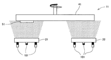
ところで上記図1〜2の装置では平板状被処理部材(基材)への成膜は可能であるが、例えば棒状被処理部材(基材)への成膜は難しく、被処理部材の形状が制限される。また図2の装置では、片方の蒸発源を使用している間、他方の蒸発源は使用できないため、成膜の効率が低い。そこで下記の図3に示す装置を用いることが推奨される。図3に示す装置を用いれば、これら不具合が解消できる。 By the way, although it is possible to form a film on a flat plate-like member (base material) in the apparatus shown in FIGS. 1 and 2, it is difficult to form a film on a rod-like member (base material). Limited. In the apparatus shown in FIG. 2, the efficiency of film formation is low because one evaporation source cannot be used while the other evaporation source is used. Therefore, it is recommended to use the apparatus shown in FIG. If the apparatus shown in FIG. 3 is used, these problems can be solved.
図3の成膜装置13では、真空チャンバー8内に回転盤72が配設されており、この回転盤72に4個の回転テーブル71が対称に取り付けられ、各回転テーブル71には被処理被材(基材)51が取り付けられている。そして回転盤72の周囲には、第1の蒸発源(図示例ではアーク式蒸発源)25、26と、第2の蒸発源(図示例ではスパッタリング式蒸発源)27、28とからなる2組の蒸発源が配置されている。これら蒸発源は、第1組と第2組とが互いに隣り合うように交互に配置されている。
In the
そして片方の組の蒸発源に前記ターゲット(1c)及び/又は(1d)を用い、他方の組の蒸発源に前記ターゲット(2c)及び/又は(2d)を用い、これらを成膜用ガス(N源含有ガス、C源及びN源含有ガス、又はこれらを不活性ガスで希釈したものなど)中で蒸発させながら、回転盤72及び回転テーブル71を回転させれば、被処理部材51が第1組の蒸発源25、26の正面と第2組の蒸発源27、28の正面を交互に通過するため、被処理部材51に第1の層と第2の層とを交互に複数回積層させることができ、積層型硬質皮膜を製造できる。この図3の装置では、全ての蒸発源を常時有効利用でき、成膜の効率が非常に高い。また個々の層の厚さは基板の回転速度あるいは蒸発源に投入するパワー(蒸発速度)によって制御できる。
Then, the target (1c) and / or (1d) is used as one set of evaporation sources, and the target (2c) and / or (2d) is used as the other set of evaporation sources. If the
なお図3の例では、磁場印加機構101により発生および制御されるアーク式蒸発源25、26の磁場111とスパッタリング式蒸発源27、28の磁場112とが互いにつながることなく独立しているが、前記磁場111、112同士がつながってもよい。磁場111、112同士がつながらない場合には、両蒸発源25、26、27、28からの放出電子が、被処理部材51のみならず、該被処理部材51と同様にアノードとなるチャンバー8に向けても誘導される。これに対し、磁場111、112の両方がつながる場合には、チャンバー8内の磁場(磁力線)が閉じた状態(閉磁場構造)になり、両蒸発源25、26、27、28からの放出電子がこの閉磁場構造内にトラップされるため、被処理部材51への指向性が高まり、成膜効率及び皮膜特性が向上する。
In the example of FIG. 3, the
さらに図3の例(及び前記図1の例)では回転運度を利用したが、被処理部材51が交互に蒸発源の前を通過する方式であれば、回転運動方式に限定されず、種々の運動方式を採用できる。例えば、蒸発源を直線上に配置し、これら蒸発源の正面側で被処理部材を直線的に往復運動させることによっても積層型皮膜は形成できる。
Further, in the example of FIG. 3 (and in the example of FIG. 1), the rotational mobility is used. However, as long as the
[単層型硬質皮膜]
本発明の硬質皮膜は、上記積層型皮膜に限定されない。CrAlの(炭)窒化物中にZr及び/又はHfを添加し、CrAlZrHf(炭)窒化物の均一膜を形成しても、積層型皮膜と同様の効果が得られる。この単層型硬質皮膜は、より具体的には、下記式(3a)で示される物質からなる皮膜である。
(Cr(1-p-q-r)AlpZrqHfr)(C(1-z)Nz) …(3a)
[式中の添字は、原子比を示す。ただしq及びrは、片方が0であってもよい。またpは0.2以上、0.7以下である。p以外の添字は、pが0.5未満の場合とpが0.5以上の場合とに応じて、以下の関係を満足する。
pが0.5未満の場合(すなわち0.2≦p<0.5の場合):
0.2≦(q+r)≦0.5
0.05≦(1−p−q−r)
0.5≦z≦1
pが0.5以上の場合(すなわち0.5≦p≦0.7の場合):
0.05≦(q+r)≦0.25
0.15≦(1−p−q−r)
0.5≦z≦1 ]
[Single layer hard coating]
The hard film of the present invention is not limited to the laminated film. Even if Zr and / or Hf is added to the CrAl (carbon) nitride to form a uniform film of CrAlZrHf (carbon) nitride, the same effect as that of the multilayer coating can be obtained. More specifically, this single-layer hard coating is a coating made of a substance represented by the following formula (3a).
(Cr (1-pqr) Al p Zr q Hf r) (C (1-z) N z) ... (3a)
[Subscripts in the formula indicate atomic ratios. However, one of q and r may be 0. Moreover, p is 0.2 or more and 0.7 or less. Subscripts other than p satisfy the following relationship, depending on whether p is less than 0.5 and p is 0.5 or more.
When p is less than 0.5 (ie, 0.2 ≦ p <0.5):
0.2 ≦ (q + r) ≦ 0.5
0.05 ≦ (1-pqr)
0.5 ≦ z ≦ 1
When p is 0.5 or more (that is, when 0.5 ≦ p ≦ 0.7):
0.05 ≦ (q + r) ≦ 0.25
0.15 ≦ (1-pqr)
0.5 ≦ z ≦ 1]
前記式(3a)において添字pはAlの原子比を示すものである。Alは、積層型硬質皮膜の場合と同様、皮膜の硬度と耐酸化性を高めるために必須であり、Al比は所定値以上にする必要がある。しかしAl比を大きくし過ぎると、軟質な六方晶型結晶構造が析出しやすくなる。これらの観点から、Al比は、0.2以上(好ましくは0.25以上、さらに好ましくは0.3以上)、0.7以下(好ましくは0.65以下、さらに好ましくは0.6以下)にする。 In the formula (3a), the subscript p indicates the atomic ratio of Al. Al is indispensable for enhancing the hardness and oxidation resistance of the coating, as in the case of the laminated hard coating, and the Al ratio needs to be a predetermined value or more. However, if the Al ratio is increased too much, a soft hexagonal crystal structure tends to precipitate. From these viewpoints, the Al ratio is 0.2 or more (preferably 0.25 or more, more preferably 0.3 or more), 0.7 or less (preferably 0.65 or less, more preferably 0.6 or less). To.
一方、前記式(3a)において、ZrとHfの合計比(q+r)やCr比(1−p−q−r)の範囲は、Al比(p)に応じて異なる。Al比(p)が0.5未満の場合、Alの役割(硬度及び耐酸化性の向上)を、ZrやHfで十分に補う必要があり、Zr及び/又はHfを十分に添加する必要がある。一方、Al比(p)が0.5以上にする場合、ZrとHfの添加量は相対的に少なくてよい。むしろAl比(p)が0.5以上の場合、ZrやHfが多くなると、結晶構造が六方晶型に転移しやすくなるため、ZrやHfは比較的少なくする必要がある。またCr比(1−p−q−r)は、前記Al比(p)とZr及びHfの合計比(q+r)と皮膜特性とのバランスから決定される。ZrとHfの合計比(q+r)やCr比(1−p−q−r)の詳細は、以下の通りである。 On the other hand, in the formula (3a), the range of the total ratio (q + r) of Zr and Hf and the Cr ratio (1-pqr) differs depending on the Al ratio (p). When the Al ratio (p) is less than 0.5, the role of Al (improvement of hardness and oxidation resistance) needs to be sufficiently supplemented with Zr and Hf, and Zr and / or Hf must be sufficiently added. is there. On the other hand, when the Al ratio (p) is 0.5 or more, the amount of Zr and Hf added may be relatively small. Rather, when the Al ratio (p) is 0.5 or more, if Zr or Hf increases, the crystal structure tends to transition to the hexagonal crystal form. Therefore, Zr and Hf need to be relatively small. The Cr ratio (1-pqr) is determined from the balance between the Al ratio (p), the total ratio of Zr and Hf (q + r), and the film properties. Details of the total ratio (q + r) and the Cr ratio (1-pqr) of Zr and Hf are as follows.
(1)Al比(p)が0.5未満の場合
ZrとHfの合計比(q+r)は、0.2以上(好ましくは0.23以上、さらに好ましくは0.25以上)、0.5以下(好ましくは0.47以下、さらに好ましくは0.45以下)である。
Cr比(1−p−q−r)は、0.05以上、好ましくは0.1以上、さらに好ましくは0.15以上である。
(1) When the Al ratio (p) is less than 0.5 The total ratio (q + r) of Zr and Hf is 0.2 or more (preferably 0.23 or more, more preferably 0.25 or more), 0.5 Or less (preferably 0.47 or less, more preferably 0.45 or less).
The Cr ratio (1-pqr) is 0.05 or more, preferably 0.1 or more, more preferably 0.15 or more.
(2)Al比(p)が0.5以上の場合
ZrとHfの合計比(q+r)は、0.05以上(好ましくは0.08以上、さらに好ましくは0.1以上)、0.25以下(好ましくは0.22以下、さらに好ましくは0.2以下)である。
Cr比(1−p−q−r)は、0.15以上、好ましくは0.15以上、さらに好ましくは0.2以上である。
(2) When the Al ratio (p) is 0.5 or more The total ratio (q + r) of Zr and Hf is 0.05 or more (preferably 0.08 or more, more preferably 0.1 or more), 0.25 Or less (preferably 0.22 or less, more preferably 0.2 or less).
The Cr ratio (1-pqr) is 0.15 or more, preferably 0.15 or more, more preferably 0.2 or more.
なおAl比(p)の範囲に拘わらず、ZrとHfは片方だけを添加してもよく、両方を添加してもよい。従ってqとrは、片方が0であってもよい。 Regardless of the range of the Al ratio (p), only one of Zr and Hf may be added, or both may be added. Therefore, one of q and r may be 0.
またN比(z)は、Al比(p)の範囲に拘わらず、0.5〜1、好ましくは0.8〜1である。N比(z)の限定理由は、積層型硬質皮膜の場合と同様である。 The N ratio (z) is 0.5 to 1, preferably 0.8 to 1, regardless of the range of the Al ratio (p). The reason for limiting the N ratio (z) is the same as in the case of the laminated hard coating.
単層型硬質皮膜は、前記積層型硬質皮膜と同様、さらにSi及び/又はBを含有していてもよい。このSi及び/又はBを含有する単層型硬質皮膜は、下記式(3b)で示される[なお下記式(3b)は、Bが炭窒化物を形成したもののみならず、Bが、Cr、Al、Zr、Hf、Siなどと硼化物を形成したものも含む]。
(Cr(1-p-q-r-s-t)AlpZrqHfrSisBt)(C(1-z)Nz) …(3b)
[式中の添字は、原子比を示す。ただしq及びrは、片方が0であってもよい。またs及びtも、片方が0であってもよい。pは0.2以上、0.7以下である。p以外の添字は、pが0.5未満の場合とpが0.5以上の場合とに応じて、以下の関係を満足する;
pが0.5未満の場合(すなわち0.2≦p<0.5の場合):
0.2≦(q+r)≦0.5
0<(s+t)≦0.2
0.05≦(1−p−q−r−s−t)
0.5≦z≦1
pが0.5以上の場合(すなわち0.5≦p≦0.7の場合):
0.05≦(q+r)≦0.25
0<(s+t)≦0.2
0.15≦(1−p−q−r−s−t)
0.5≦z≦1 ]
The single-layer type hard coating may further contain Si and / or B as in the case of the laminated hard coating. This single layer type hard coating containing Si and / or B is represented by the following formula (3b) [Note that the following formula (3b) is not only the one in which B forms a carbonitride, but the B is Cr. , And borides with Al, Zr, Hf, Si, etc.].
(Cr (1-pqrst) Al p Zr q Hf r Si s B t) (C (1-z) N z) ... (3b)
[Subscripts in the formula indicate atomic ratios. However, one of q and r may be 0. One of s and t may be 0. p is 0.2 or more and 0.7 or less. Subscripts other than p satisfy the following relationship, depending on whether p is less than 0.5 and p is greater than or equal to 0.5:
When p is less than 0.5 (ie, 0.2 ≦ p <0.5):
0.2 ≦ (q + r) ≦ 0.5
0 <(s + t) ≦ 0.2
0.05 ≦ (1-pqr−s−t)
0.5 ≦ z ≦ 1
When p is 0.5 or more (that is, when 0.5 ≦ p ≦ 0.7):
0.05 ≦ (q + r) ≦ 0.25
0 <(s + t) ≦ 0.2
0.15 ≦ (1-pqr−s−t)
0.5 ≦ z ≦ 1]
Al比(p)、ZrとHfの合計比(q+r)、N比(z)の限定理由及び好ましい範囲は、前記式(3a)と同じである。Cr比(1−p−q−r−s−t)の限定理由及び好ましい範囲は、前記式(3a)のCr比(1−p−q−r)と同じである。“s+t”の限定理由及び好ましい範囲は、前記“b+c”の場合と同じである。またs及びtの片方が0になってよい理由等についても、前記b、cの場合と同様である。 The reasons for limitation and the preferred range of the Al ratio (p), the total ratio of Zr and Hf (q + r), and the N ratio (z) are the same as in the formula (3a). The reason for limitation and the preferred range of the Cr ratio (1-pqr-st) are the same as the Cr ratio (1-pqr) of the formula (3a). The reason for limitation and the preferred range of “s + t” are the same as in the case of “b + c”. The reason why one of s and t may be 0 is the same as in the case of b and c.
単層型硬質皮膜は、前述の積層型硬質皮膜と同様にして製造でき、例えば化学気相成長法(CVD法)を利用して形成してもよいが、物理気相成長法(PVD法)、特にスパッタリング法、イオンプレーティング法(アークイオンプレーティング法など)などを利用して形成することが好ましい。 The single-layer type hard coating can be produced in the same manner as the above-described laminated hard coating, and may be formed using, for example, chemical vapor deposition (CVD), but physical vapor deposition (PVD) In particular, it is preferable to use a sputtering method, an ion plating method (an arc ion plating method, etc.) or the like.
PVD法による場合、下記式(3c)又は(3d)で示されるターゲットを用い、C/N比(原子比)が0.5/0.5〜0/1の(炭)窒化物層を形成することによって、単層型硬質皮膜を形成できる。
Cr(1-p-q-r)AlpZrqHfr …(3c)
Cr(1-p-q-r-s-t)AlpZrqHfrSisBt …(3d)
[式中の添字は、原子比を示す。またその値は、前記式(3a)、(3b)と同じである]
When the PVD method is used, a (carbon) nitride layer having a C / N ratio (atomic ratio) of 0.5 / 0.5 to 0/1 is formed using a target represented by the following formula (3c) or (3d). By doing so, a single layer type hard film can be formed.
Cr (1-pqr) Al p Zr q Hf r ... (3c)
Cr (1-pqrst) Al p Zr q Hf r Si s B t ... (3d)
[Subscripts in the formula indicate atomic ratios. Moreover, the value is the same as said Formula (3a) and (3b)]
単層型硬質皮膜は、前述の積層型硬質皮膜と同様、立方晶型結晶構造を示すことが推奨される。 It is recommended that the single-layer type hard coating exhibits a cubic crystal structure as in the case of the above-described laminated hard coating.
本発明の硬質皮膜(積層型硬質皮膜、単層型硬質皮膜)の厚さは、例えば、1000nm以上(好ましくは2000nm以上)、10000nm以下(特に5000nm以下)程度であることが多い。 The thickness of the hard coating (laminated hard coating, single layer hard coating) of the present invention is often about 1000 nm or more (preferably 2000 nm or more) and 10,000 nm or less (particularly 5000 nm or less).
本発明の硬質皮膜は、CrAlの(炭)窒化物(CrAlCN、CrAlNなど)を、ZrやHfと適切に組み合わせているため、高温特性がより一層向上している。 Since the hard coating of the present invention appropriately combines CrAl (carbon) nitride (CrAlCN, CrAlN, etc.) with Zr and Hf, the high temperature characteristics are further improved.
以下、実施例を挙げて本発明をより具体的に説明するが、本発明はもとより下記実施例によって制限を受けるものではなく、前・後記の趣旨に適合し得る範囲で適当に変更を加えて実施することも勿論可能であり、それらはいずれも本発明の技術的範囲に包含される。 EXAMPLES Hereinafter, the present invention will be described more specifically with reference to examples. However, the present invention is not limited by the following examples, but may be appropriately modified within a range that can meet the purpose described above and below. Of course, it is possible to implement them, and they are all included in the technical scope of the present invention.
以下の実験例では、(1)鏡面研磨した超硬合金製チップ(皮膜組成、結晶構造、および硬度測定用)、(2)超硬合金製ボールエンドミル(直径10mm、二枚刃)(磨耗幅測定用)、および(3)白金箔(30×5×0.1mmt)(酸化開始温度測定用)の3種類の被処理部材の表面に硬質皮膜を形成するものとし、得られた硬質皮膜の物性は、下記の方法に従って求めた。 In the following experimental examples, (1) mirror-finished cemented carbide tip (for coating composition, crystal structure and hardness measurement), (2) cemented carbide ball end mill (diameter 10 mm, two blades) (wear width) And (3) platinum foil (30 × 5 × 0.1 mmt) (for measurement of oxidation start temperature), a hard film is formed on the surface of the three kinds of treated members, The physical properties were determined according to the following methods.
[硬質皮膜の組成]
皮膜中の金属元素の成分組成は、EDX(Energy Dispersive X-ray Fluorescence Spectroscopy )法で定量分析[加速電圧:20kV、WD(Work Distance):15mm、測定時間(Live):60秒、ZAF補正]することによって決定した。
[Composition of hard coating]
The component composition of the metal element in the film is quantitatively analyzed by an EDX (Energy Dispersive X-ray Fluorescence Spectroscopy) method [acceleration voltage: 20 kV, WD (Work Distance): 15 mm, measurement time (Live): 60 seconds, ZAF correction] Decided by.
[結晶構造]
リガク電機社製のX線回折装置を用い、X線回折法[θ−2θ法、CuKα線(40kV−40mA)]によって、硬質皮膜のX線回折ピークを調べた。2θ=37.78°付近のピークが立方晶の(111)面に相当し、2θ=43.9°付近のピークが立方晶の(200)面に相当し、2θ=63.8°付近のピークが立方晶の(220)面に相当する。また2θ=32°〜33°付近のピークが六方晶の(100)面に相当し、2θ=48°〜50°付近のピークが六方晶の(102)面に相当し、2θ=57°〜58°付近のピークが六方晶の(110)面に相当する。各ピークの強度を測定し、下記式(4)に従って結晶構造指数Xを算出し、下記基準に従って皮膜の結晶構造を決定した。
[Crystal structure]
Using an X-ray diffractometer manufactured by Rigaku Electric Co., Ltd., the X-ray diffraction peak of the hard coating was examined by the X-ray diffraction method [θ-2θ method, CuKα ray (40 kV-40 mA)]. The peak near 2θ = 37.78 ° corresponds to the (111) plane of the cubic crystal, the peak near 2θ = 43.9 ° corresponds to the (200) plane of the cubic crystal, and the peak near 2θ = 63.8 °. The peak corresponds to the cubic (220) plane. The peak near 2θ = 32 ° to 33 ° corresponds to the (100) plane of hexagonal crystal, and the peak near 2θ = 48 ° to 50 ° corresponds to the (102) plane of hexagonal crystal, and 2θ = 57 ° to The peak near 58 ° corresponds to the (110) plane of hexagonal crystal. The intensity of each peak was measured, the crystal structure index X was calculated according to the following formula (4), and the crystal structure of the film was determined according to the following criteria.

(式中、IB(111)、IB(200)およびIB(220)は立方晶の各面のピーク強度を示す。IH(100)、IH(102)およびIH(110)は六方晶の各面のピーク強度を示す)
指数Xが0.9以上の場合:立方晶型結晶構造(下記表中、B1と表記する)
指数Xが0.1以上、0.9未満の場合:混合型(下記表中、B1+B4と表記する)
指数Xが0.1未満の場合:六方晶結晶構造(下記表中、B4と表記する)
(In the formula, IB (111), IB (200) and IB (220) indicate the peak intensity of each face of the cubic crystal. IH (100), IH (102) and IH (110) are the faces of the hexagonal crystal. Shows peak intensity)
When the index X is 0.9 or more: Cubic crystal structure (denoted as B1 in the table below)
When the index X is 0.1 or more and less than 0.9: Mixed type (denoted as B1 + B4 in the table below)
When the index X is less than 0.1: hexagonal crystal structure (denoted as B4 in the table below)
[硬度]
硬度は、マイクロビッカース硬度計を用い、荷重0.25N、保持時間15秒の条件で測定した。
[hardness]
The hardness was measured using a micro Vickers hardness tester under conditions of a load of 0.25 N and a holding time of 15 seconds.
[酸化開始温度]
下記実験例で得られた白金サンプル(白金箔に硬質皮膜を形成したもの)を人工乾燥空気中で室温から5℃/minの昇温速度で加熱し、その重量変化を熱天秤で調べた。得られた重量増加曲線から酸化開始温度を決定した。
[Oxidation start temperature]
Platinum samples obtained by the following experimental examples (platinum foils having a hard film formed) were heated in an artificial dry air from room temperature to a heating rate of 5 ° C./min, and the weight change was examined with a thermobalance. The oxidation start temperature was determined from the obtained weight increase curve.
[磨耗幅]
下記実験例で得られた試験用エンドミル[超硬合金製エンドミル(直径10mm、2枚刃)の表面に硬質皮膜を形成したもの]を用い、SKD61焼き入れ鋼(HRC50)を、下記の切削条件で切削した後、刃先を光学顕微鏡で観察し、すくい面と逃げ面の境界部分の摩耗幅を測定した。
切削速度:220m/分
刃送り :0.05mm/刃
深さ切り込み:4.5mm
軸切り込み :1mm
その他:ドライカット、エアーブロー
[Wear width]
Using an end mill for testing obtained in the following experimental example [with a hard coating formed on the surface of a cemented carbide end mill (diameter: 10 mm, 2 blades)], SKD61 hardened steel (HRC50) was subjected to the following cutting conditions. After cutting, the cutting edge was observed with an optical microscope, and the wear width at the boundary between the rake face and the flank face was measured.
Cutting speed: 220 m / min Blade feed: 0.05 mm / blade Depth cut: 4.5 mm
Shaft cut: 1mm
Others: dry cut, air blow
実験例1
図3に示した成膜装置13を用い、CrとAlからなるターゲット(組成は表1の第1の層とほぼ同じ)をアーク式蒸発源25、26に装着し、ZrとHfからなるターゲット(組成は表1の第2の層とほぼ同じ)をスパッタリング式蒸発源27、28に装着した。また被処理部材(チップ、ボールエンドミル、又は白金箔)51をエタノールで脱脂洗浄した後、回転テーブル71上に取り付け、チャンバー8内を真空にした。ヒーター(図示せず)によって温度約500℃まで加熱し、回転盤72及び回転テーブル71によって被処理部材51を回転させつつ、Arイオンを導入してクリーニングを実施した。次いで成膜用ガスを導入しながら、各蒸発源25、26、27、28を放電させて、厚さが3μmになるまで積層型硬質皮膜を形成した。前記成膜用ガスはAr−N2混合ガス又はAr−N2−CH4の混合ガスであり、全圧力は2.6Paであり、反応ガスの分圧(N2の分圧とCH4の分圧の合計)は1.3Paに固定した。また第1の層と第2の層の厚さは、蒸発源へ投入する電力及び被処理部材51の回転周期により調節した。
Experimental example 1
Using the
得られた硬質皮膜の物性を表1に示す。 Table 1 shows the physical properties of the hard coating obtained.
表1のNo.11〜23は、本発明の積層型硬質皮膜に相当する。これら積層型硬質皮膜は、従来の硬質皮膜(表1のNo.i〜iii参照)に比べ、硬度、酸化開始温度、摩耗幅などの点で優れている。 No. in Table 1 11 to 23 correspond to the laminated hard coating of the present invention. These laminated hard coatings are superior to conventional hard coatings (see Nos. I to iii in Table 1) in terms of hardness, oxidation start temperature, wear width, and the like.
実験例2
Cr・Al・Si・Bからなるターゲット(組成は表2の第1の層とほぼ同じ)をアーク式蒸発源25、26に装着し、Zr・Hf・Si・Bからなるターゲット(組成は表1の第2の層とほぼ同じ)をスパッタリング式蒸発源27、28に装着する以外は、前記実験例1と同様にした。
Experimental example 2
A target made of Cr.Al.Si.B (composition is almost the same as that of the first layer in Table 2) is mounted on the
得られた硬質皮膜の物性を表2に示す。 Table 2 shows the physical properties of the hard coating obtained.
表2のNo.3〜9は、本発明の積層型硬質皮膜に相当する。これら積層型硬質皮膜は、従来の硬質皮膜(表1のNo.i〜iii参照)に比べ、硬度、酸化開始温度、摩耗幅などの点で優れている。 No. in Table 2 3 to 9 correspond to the laminated hard coating of the present invention. These laminated hard coatings are superior to conventional hard coatings (see Nos. I to iii in Table 1) in terms of hardness, oxidation start temperature, wear width, and the like.
実験例3
蒸発源25、26、27、28の方式をアークイオンプレーティング式に統一し、これら蒸発源25、26、27、28にCr・Al・Zr・Hfからなるターゲット(組成は表3とほぼ同じ)を装着すると共に、成膜用ガスをN2ガス(全圧力:4Pa)又はN2−CH4混合ガス(N2分圧:2.7Pa、CH4分圧:1.3Pa、全圧力:4Pa)にする以外は、前記実験例1と同様にした。
Experimental example 3
得られた硬質皮膜の物性を表3に示す。 Table 3 shows the physical properties of the obtained hard coating.
表3のNo.3〜5及び10〜11は、本発明の硬質皮膜に相当する。これら硬質皮膜は、従来の硬質皮膜(表3のNo.i〜iii参照)に比べ、硬度、酸化開始温度、摩耗幅などの点で優れている。 No. in Table 3 3-5 and 10-11 correspond to the hard coating of the present invention. These hard coatings are superior to conventional hard coatings (see No. i to iii in Table 3) in terms of hardness, oxidation start temperature, wear width, and the like.
実験例4
Cr・Al・Zr・Hf・Si・Bから成るターゲット(組成は表4とほぼ同じ)を装着する以外は、実験例3と同様にした。
Experimental Example 4
Example 3 was the same as Example 3 except that a target composed of Cr, Al, Zr, Hf, Si, and B (composition was almost the same as Table 4) was mounted.
得られた硬質皮膜の物性を表4に示す。 Table 4 shows the physical properties of the obtained hard film.
表4のNo.2〜5及び7〜8は、本発明の硬質皮膜に相当する。これら硬質皮膜は、従来の硬質皮膜(表4のNo.i〜iii参照)に比べ、硬度、酸化開始温度、摩耗幅などの点で優れている。 No. in Table 4 2-5 and 7-8 correspond to the hard film of the present invention. These hard coatings are superior to conventional hard coatings (see No. i to iii in Table 4) in terms of hardness, oxidation start temperature, wear width, and the like.
本発明の硬質皮膜は、硬度、酸化開始温度、ドライ環境で高速度の切削を行った場合の摩耗幅などの点で優れ、高温特性が改善されているため、工具や金型のコーティング皮膜(硬質皮膜)として好適に用いることができ、それらの耐久性を向上できる。例えば、高速度工具鋼(SKH51、SKD11、SKD61など)や超硬合金などの鉄系基材の表面に形成することで、硬度や耐酸化性に優れた切削工具や治工具を得ることができる。 The hard coating of the present invention is excellent in terms of hardness, oxidation start temperature, wear width when cutting at high speed in a dry environment, etc., and has improved high temperature characteristics. (Hard film) can be suitably used, and their durability can be improved. For example, by forming on the surface of an iron-based substrate such as high-speed tool steel (SKH51, SKD11, SKD61, etc.) or cemented carbide, it is possible to obtain cutting tools and jigs with excellent hardness and oxidation resistance. .
21、22、23、24、25、26、27、28:蒸発源(ターゲット)
51:被処理部材
21, 22, 23, 24, 25, 26, 27, 28: Evaporation source (target)
51: Processed member
Claims (5)
(Cr(1-a)Ala)(C(1-x)Nx) …(1a)
(Zr(1-k)Hfk)(C(1-y)Ny) …(2a)
[式中の添字は、原子比を示す;これら添字は、以下の関係を満足する;
0.2≦a≦0.67
0.7≦x≦1
0≦k≦1
0.5≦y≦1 ] A plurality of first layers represented by the following formula (1a) and having a thickness of 1 to 80 nm and second layers represented by the following formula (2a) and having a thickness of 1 to 80 nm alternately Laminated hard coating that is laminated.
(Cr (1-a) Al a ) (C (1-x) N x ) (1a)
(Zr (1-k) Hf k) (C (1-y) N y) ... (2a)
[Subscripts in the formula indicate atomic ratios; these subscripts satisfy the following relationship;
0.2 ≦ a ≦ 0.67
0.7 ≦ x ≦ 1
0 ≦ k ≦ 1
0.5 ≦ y ≦ 1]
(Cr(1-a’-b-c)Ala’SibBc)(C(1-x)Nx) …(1b)
[式中の添字は、原子比を示す;b及びcは、片方が0であってもよい;これら添字は、以下の関係を満足する;
0.2≦a’≦0.57
0<(b+c)≦0.1
0.7≦x≦1 ] The multilayer hard coating according to claim 1, wherein at least a part of the plurality of first layers is replaced with a layer represented by the following formula (1b) and having a thickness of 1 to 80 nm.
(Cr (1-a′-bc) Al a ′ Si b B c ) (C (1-x) N x ) (1b)
[Subscripts in formula indicate atomic ratio; b and c may be 0 on one side; these subscripts satisfy the following relationship;
0.2 ≦ a ′ ≦ 0.57
0 <(b + c) ≦ 0.1
0.7 ≦ x ≦ 1]
(Zr(1-k-m-n)HfkSimBn)(C(1-y)Ny) …(2b)
[式中の添字は、原子比を示す;m及びnは、片方が0であってもよい;これら添字は、以下の関係を満足する;
0≦k≦1−m−n
0<(m+n)≦0.2
0.5≦y≦1 ] The multilayer hard coating according to claim 1 or 2, wherein at least a part of the plurality of second layers is replaced with a layer represented by the following formula (2b) and having a thickness of 1 to 80 nm. .
(Zr (1-kmn) Hf k Si m B n) (C (1-y) N y) ... (2b)
[Subscripts in formula indicate atomic ratio; m and n may be 0 on one side; these subscripts satisfy the following relationship;
0 ≦ k ≦ 1-mn
0 <(m + n) ≦ 0.2
0.5 ≦ y ≦ 1]
下記式(2c)又は(2d)で示されるターゲットを用い、イオンプレーティング法又はスパッタリング法によって、厚さが1〜80nmであってC/N比(原子比)が0.5/0.5〜0/1の窒化物層又は炭窒化物層を第2の層として形成する工程とを交互に複数回繰り返すことによって得られる積層型硬質皮膜。
Cr(1-a)Ala …(1c)
Cr(1-a’-b-c)Ala’SibBc …(1d)
Zr(1-k)Hfk …(2c)
Zr(1-k-m-n)HfkSimBn …(2d)
[式中の添字は、原子比を示す;b及びcは、片方が0であってもよい;またm及びnも、片方が0であってもよい;これら添字は、以下の関係を満足する;
0.2≦a≦0.67
0.2≦a’≦0.57
0<(b+c)≦0.1
0≦k≦1(式2cの場合)又は0≦k≦1−m−n(式2dの場合)
0<(m+n)≦0.2 ] Using a target represented by the following formula (1c) or (1d), the thickness is 1 to 80 nm and the C / N ratio (atomic ratio) is 0.3 / 0.7 by ion plating or sputtering. Forming a ~ 0/1 nitride or carbonitride layer as the first layer;
Using a target represented by the following formula (2c) or (2d), the thickness is 1 to 80 nm and the C / N ratio (atomic ratio) is 0.5 / 0.5 by ion plating or sputtering. A laminated hard coating obtained by alternately repeating a step of forming a ~ 0/1 nitride layer or carbonitride layer as a second layer alternately.
Cr (1-a) Al a (1c)
Cr (1-a′-bc) Al a ′ Si b B c (1d)
Zr (1-k) Hf k (2c)
Zr (1-kmn) Hf k Si m B n (2d)
[The subscripts in the formulas indicate atomic ratios; b and c may be zero on one side; and m and n may be zero on one side; these subscripts satisfy the following relationship: Do;
0.2 ≦ a ≦ 0.67
0.2 ≦ a ′ ≦ 0.57
0 <(b + c) ≦ 0.1
0 ≦ k ≦ 1 (in the case of formula 2c) or 0 ≦ k ≦ 1-mn (in the case of formula 2d)
0 <(m + n) ≦ 0.2]
Priority Applications (7)
| Application Number | Priority Date | Filing Date | Title |
|---|---|---|---|
| JP2006012092A JP5138892B2 (en) | 2006-01-20 | 2006-01-20 | Hard coating |
| US11/466,671 US7510608B2 (en) | 2006-01-20 | 2006-08-23 | Hard coating film |
| DE102006047414A DE102006047414B4 (en) | 2006-01-20 | 2006-10-06 | Hard coating and process for its production |
| DE102006062798.9A DE102006062798B4 (en) | 2006-01-20 | 2006-10-06 | Laminate hard coating and method of making the same |
| CNB2006101321109A CN100553968C (en) | 2006-01-20 | 2006-10-10 | Hard coating |
| KR1020070005180A KR100837018B1 (en) | 2006-01-20 | 2007-01-17 | Hard coating film |
| US12/354,355 US7592061B1 (en) | 2006-01-20 | 2009-01-15 | Hard coating film |
Applications Claiming Priority (1)
| Application Number | Priority Date | Filing Date | Title |
|---|---|---|---|
| JP2006012092A JP5138892B2 (en) | 2006-01-20 | 2006-01-20 | Hard coating |
Related Child Applications (1)
| Application Number | Title | Priority Date | Filing Date |
|---|---|---|---|
| JP2012149494A Division JP5416813B2 (en) | 2012-07-03 | 2012-07-03 | Hard coating |
Publications (3)
| Publication Number | Publication Date |
|---|---|
| JP2007191765A JP2007191765A (en) | 2007-08-02 |
| JP2007191765A5 JP2007191765A5 (en) | 2008-12-18 |
| JP5138892B2 true JP5138892B2 (en) | 2013-02-06 |
Family
ID=38268331
Family Applications (1)
| Application Number | Title | Priority Date | Filing Date |
|---|---|---|---|
| JP2006012092A Expired - Fee Related JP5138892B2 (en) | 2006-01-20 | 2006-01-20 | Hard coating |
Country Status (5)
| Country | Link |
|---|---|
| US (2) | US7510608B2 (en) |
| JP (1) | JP5138892B2 (en) |
| KR (1) | KR100837018B1 (en) |
| CN (1) | CN100553968C (en) |
| DE (2) | DE102006047414B4 (en) |
Families Citing this family (20)
| Publication number | Priority date | Publication date | Assignee | Title |
|---|---|---|---|---|
| JP5096715B2 (en) | 2006-09-21 | 2012-12-12 | 株式会社神戸製鋼所 | Hard coating and hard coating tool |
| JP5003947B2 (en) * | 2007-06-07 | 2012-08-22 | 住友電工ハードメタル株式会社 | Surface coated cutting tool |
| US8080324B2 (en) * | 2007-12-03 | 2011-12-20 | Kobe Steel, Ltd. | Hard coating excellent in sliding property and method for forming same |
| US20110186420A1 (en) * | 2008-06-09 | 2011-08-04 | Nanofilm Technologies International Pte Ltd | Method for rapid deposition of a coating on a substrate |
| JP5234931B2 (en) * | 2008-06-23 | 2013-07-10 | 株式会社神戸製鋼所 | Hard coating member and molding tool |
| JP5692636B2 (en) * | 2010-11-16 | 2015-04-01 | 三菱マテリアル株式会社 | Surface coated cutting tool |
| JP5035479B2 (en) * | 2011-01-27 | 2012-09-26 | 三菱マテリアル株式会社 | Surface coated cutting tool with excellent chipping resistance and wear resistance |
| JP6028374B2 (en) * | 2011-06-29 | 2016-11-16 | 大同特殊鋼株式会社 | Target and hard coating coated cutting tool |
| JP5764002B2 (en) * | 2011-07-22 | 2015-08-12 | 株式会社神戸製鋼所 | Vacuum deposition system |
| JP2014122400A (en) | 2012-12-21 | 2014-07-03 | Kobe Steel Ltd | Hard film excellent in cohesion resistance to soft metal |
| US9896767B2 (en) | 2013-08-16 | 2018-02-20 | Kennametal Inc | Low stress hard coatings and applications thereof |
| CN105584148B (en) * | 2014-10-22 | 2017-09-12 | 上海航天设备制造总厂 | Hard refractory self-lubricating coat in use product and preparation method thereof |
| CN104532185B (en) * | 2014-12-22 | 2017-02-22 | 四川大学 | CrAl(C, N) hard coating of amorphous structure and preparation method of hard coating |
| JP2016199793A (en) * | 2015-04-13 | 2016-12-01 | 株式会社神戸製鋼所 | Hard film |
| JP2016211052A (en) * | 2015-05-12 | 2016-12-15 | 株式会社神戸製鋼所 | Hard film and hard film coated member |
| JP6507399B2 (en) * | 2017-03-28 | 2019-05-08 | 株式会社タンガロイ | Coated cutting tool |
| JP7067689B2 (en) * | 2018-03-07 | 2022-05-16 | 住友電工ハードメタル株式会社 | Surface coating cutting tool and its manufacturing method |
| CN111526956B (en) * | 2018-03-07 | 2023-07-21 | 住友电工硬质合金株式会社 | Surface-coated cutting tool and method for manufacturing same |
| KR102074469B1 (en) * | 2019-05-13 | 2020-02-07 | 주식회사 다올플라즈마 | Multilayer Nano Hard Coating Film for Forming Tool |
| WO2022097286A1 (en) * | 2020-11-06 | 2022-05-12 | 貴嗣 飯塚 | Film formation apparatus, film formation unit and film formation method |
Family Cites Families (26)
| Publication number | Priority date | Publication date | Assignee | Title |
|---|---|---|---|---|
| JP2977066B2 (en) | 1993-05-21 | 1999-11-10 | 株式会社リケン | Sliding member |
| JPH0873289A (en) * | 1994-08-31 | 1996-03-19 | Sumitomo Electric Ind Ltd | Composite high hardness material for tool |
| JPH08134629A (en) * | 1994-09-16 | 1996-05-28 | Sumitomo Electric Ind Ltd | Hyperfine particle laminated film and laminated high hardness material for tool with same |
| JPH0941127A (en) * | 1995-08-03 | 1997-02-10 | Kobe Steel Ltd | Hard film |
| JP4028891B2 (en) * | 1995-08-19 | 2007-12-26 | ヴィディア ゲゼルシャフト ミット ベシュレンクテル ハフツング | Multi-component hard layer manufacturing method and composite |
| JPH1018024A (en) | 1996-07-05 | 1998-01-20 | Hitachi Metals Ltd | Coated hard member |
| JP3039381B2 (en) | 1996-07-12 | 2000-05-08 | 山口県 | Method of forming composite hard coating with excellent high temperature oxidation resistance |
| JPH10176289A (en) * | 1996-12-10 | 1998-06-30 | Balzers Ag | Coated hard alloy |
| JP3250967B2 (en) * | 1996-12-25 | 2002-01-28 | マルマス機械株式会社 | Coin operated rice polishing machine |
| ATE291648T1 (en) | 1998-10-27 | 2005-04-15 | Mitsubishi Mat Kobe Tools Corp | WEAR-RESISTANT COATED PART |
| JP4375691B2 (en) * | 1999-12-17 | 2009-12-02 | 住友電工ハードメタル株式会社 | Composite high hardness material |
| EP1188504B1 (en) * | 2000-09-07 | 2004-11-17 | Ngk Spark Plug Co., Ltd | Coated cutting tool |
| JP4112834B2 (en) | 2000-12-28 | 2008-07-02 | 株式会社神戸製鋼所 | Target for forming hard coatings for cutting tools |
| ATE545718T1 (en) | 2000-12-28 | 2012-03-15 | Kobe Steel Ltd | USE OF AN ARC ION PLATING TARGET FOR PRODUCING A HARD FILM |
| JP4216518B2 (en) * | 2002-03-29 | 2009-01-28 | 株式会社神戸製鋼所 | Cathode discharge type arc ion plating target and method of manufacturing the same |
| JP2004082230A (en) * | 2002-08-23 | 2004-03-18 | Hitachi Tool Engineering Ltd | Rigid film draping insert for precision lathe working |
| SE526339C2 (en) * | 2002-09-04 | 2005-08-23 | Seco Tools Ab | Cut with durable refractory coating with composite structure |
| DE10362382B3 (en) * | 2002-12-27 | 2017-08-17 | Kabushiki Kaisha Kobe Seiko Sho (Kobe Steel Co., Ltd.) | Hard coating with excellent adhesion |
| JP2004238736A (en) * | 2003-01-17 | 2004-08-26 | Hitachi Tool Engineering Ltd | Hard film, and hard film-coated tool |
| JP2004306228A (en) * | 2003-04-10 | 2004-11-04 | Hitachi Tool Engineering Ltd | Hard coating |
| JP2006524748A (en) | 2003-04-28 | 2006-11-02 | ユナキス・バルツェルス・アクチェンゲゼルシャフト | Workpiece having hard material layer containing AlCr and manufacturing method |
| US7226670B2 (en) * | 2003-04-28 | 2007-06-05 | Oc Oerlikon Balzers Ag | Work piece with a hard film of AlCr-containing material, and process for its production |
| JP4097074B2 (en) | 2003-06-17 | 2008-06-04 | ユケン工業株式会社 | Method for forming chromium nitride film |
| ES2361281T3 (en) | 2004-07-15 | 2011-06-15 | Oerlikon Trading Ag, Trübbach | HARD COATING MATERIALS, WITH HIGH RESISTANCE TO OXIDATION FOR CUTTING TOOLS. |
| JP2006082208A (en) * | 2004-09-17 | 2006-03-30 | Sumitomo Electric Hardmetal Corp | Surface coated cutting tool |
| JP2006082209A (en) * | 2004-09-17 | 2006-03-30 | Sumitomo Electric Hardmetal Corp | Surface coated cutting tool |
-
2006
- 2006-01-20 JP JP2006012092A patent/JP5138892B2/en not_active Expired - Fee Related
- 2006-08-23 US US11/466,671 patent/US7510608B2/en not_active Expired - Fee Related
- 2006-10-06 DE DE102006047414A patent/DE102006047414B4/en not_active Expired - Fee Related
- 2006-10-06 DE DE102006062798.9A patent/DE102006062798B4/en not_active Expired - Fee Related
- 2006-10-10 CN CNB2006101321109A patent/CN100553968C/en not_active Expired - Fee Related
-
2007
- 2007-01-17 KR KR1020070005180A patent/KR100837018B1/en active IP Right Grant
-
2009
- 2009-01-15 US US12/354,355 patent/US7592061B1/en not_active Expired - Fee Related
Also Published As
| Publication number | Publication date |
|---|---|
| US7510608B2 (en) | 2009-03-31 |
| KR100837018B1 (en) | 2008-06-10 |
| CN100553968C (en) | 2009-10-28 |
| DE102006062798B4 (en) | 2014-08-07 |
| CN101003196A (en) | 2007-07-25 |
| US20090246497A1 (en) | 2009-10-01 |
| DE102006047414B4 (en) | 2012-11-29 |
| JP2007191765A (en) | 2007-08-02 |
| KR20070077083A (en) | 2007-07-25 |
| DE102006047414A1 (en) | 2007-08-02 |
| US7592061B1 (en) | 2009-09-22 |
| US20070172694A1 (en) | 2007-07-26 |
Similar Documents
| Publication | Publication Date | Title |
|---|---|---|
| JP5138892B2 (en) | Hard coating | |
| JP4713413B2 (en) | Hard coating and method for producing the same | |
| JP4950499B2 (en) | Hard coating and method for forming the same | |
| KR100674773B1 (en) | Hard films, multilayer hard films, and production methods thereof | |
| JP5909273B2 (en) | Hard coating and method for manufacturing hard coating | |
| JP4939032B2 (en) | Hard film and method for producing hard film | |
| JP4388582B2 (en) | Hard coating layer and method for forming the same | |
| JP5043908B2 (en) | Method for forming fine crystal hard coating | |
| JP4448342B2 (en) | Fine crystal hard coating | |
| JP4408231B2 (en) | Hard laminated film and method for forming hard laminated film | |
| CN102037151A (en) | Tool having a metal oxide coating | |
| JP2010188461A (en) | Surface coated cutting tool | |
| JP5416429B2 (en) | Surface coated cutting tool | |
| IL226024A (en) | Hard film coated member and method for producing the same | |
| JP2010111952A (en) | Hard film and method for forming the same | |
| JP5416813B2 (en) | Hard coating | |
| JP2009148856A (en) | Surface-coated cutting tool | |
| JP7055961B2 (en) | Surface coating cutting tool and its manufacturing method | |
| WO2014156739A1 (en) | Laminated coating film having superior wear resistance | |
| JP4408230B2 (en) | Hard laminated film and method for forming hard laminated film | |
| JP2010150666A (en) | Hard film, laminated hard film, and method for manufacturing the same |
Legal Events
| Date | Code | Title | Description |
|---|---|---|---|
| A621 | Written request for application examination |
Free format text: JAPANESE INTERMEDIATE CODE: A621 Effective date: 20080926 |
|
| A521 | Written amendment |
Free format text: JAPANESE INTERMEDIATE CODE: A523 Effective date: 20081029 |
|
| A977 | Report on retrieval |
Free format text: JAPANESE INTERMEDIATE CODE: A971007 Effective date: 20101012 |
|
| A131 | Notification of reasons for refusal |
Free format text: JAPANESE INTERMEDIATE CODE: A131 Effective date: 20101109 |
|
| A521 | Written amendment |
Free format text: JAPANESE INTERMEDIATE CODE: A523 Effective date: 20110111 |
|
| A131 | Notification of reasons for refusal |
Free format text: JAPANESE INTERMEDIATE CODE: A131 Effective date: 20110517 |
|
| A521 | Written amendment |
Free format text: JAPANESE INTERMEDIATE CODE: A523 Effective date: 20110719 |
|
| A02 | Decision of refusal |
Free format text: JAPANESE INTERMEDIATE CODE: A02 Effective date: 20120403 |
|
| A521 | Written amendment |
Free format text: JAPANESE INTERMEDIATE CODE: A523 Effective date: 20120703 |
|
| A911 | Transfer to examiner for re-examination before appeal (zenchi) |
Free format text: JAPANESE INTERMEDIATE CODE: A911 Effective date: 20120823 |
|
| TRDD | Decision of grant or rejection written | ||
| A01 | Written decision to grant a patent or to grant a registration (utility model) |
Free format text: JAPANESE INTERMEDIATE CODE: A01 Effective date: 20121106 |
|
| A01 | Written decision to grant a patent or to grant a registration (utility model) |
Free format text: JAPANESE INTERMEDIATE CODE: A01 |
|
| A61 | First payment of annual fees (during grant procedure) |
Free format text: JAPANESE INTERMEDIATE CODE: A61 Effective date: 20121115 |
|
| R150 | Certificate of patent or registration of utility model |
Ref document number: 5138892 Country of ref document: JP Free format text: JAPANESE INTERMEDIATE CODE: R150 Free format text: JAPANESE INTERMEDIATE CODE: R150 |
|
| FPAY | Renewal fee payment (event date is renewal date of database) |
Free format text: PAYMENT UNTIL: 20151122 Year of fee payment: 3 |
|
| LAPS | Cancellation because of no payment of annual fees |