JP7204276B2 - DISCHARGED APPARATUS, FORMING APPARATUS, AND METHOD FOR MANUFACTURING MOLDED BODY - Google Patents
DISCHARGED APPARATUS, FORMING APPARATUS, AND METHOD FOR MANUFACTURING MOLDED BODY Download PDFInfo
- Publication number
- JP7204276B2 JP7204276B2 JP2018229026A JP2018229026A JP7204276B2 JP 7204276 B2 JP7204276 B2 JP 7204276B2 JP 2018229026 A JP2018229026 A JP 2018229026A JP 2018229026 A JP2018229026 A JP 2018229026A JP 7204276 B2 JP7204276 B2 JP 7204276B2
- Authority
- JP
- Japan
- Prior art keywords
- particles
- aerosol
- ejector
- fixing surface
- gas
- Prior art date
- Legal status (The legal status is an assumption and is not a legal conclusion. Google has not performed a legal analysis and makes no representation as to the accuracy of the status listed.)
- Active
Links
Images


Classifications
-
- B—PERFORMING OPERATIONS; TRANSPORTING
- B29—WORKING OF PLASTICS; WORKING OF SUBSTANCES IN A PLASTIC STATE IN GENERAL
- B29C—SHAPING OR JOINING OF PLASTICS; SHAPING OF MATERIAL IN A PLASTIC STATE, NOT OTHERWISE PROVIDED FOR; AFTER-TREATMENT OF THE SHAPED PRODUCTS, e.g. REPAIRING
- B29C64/00—Additive manufacturing, i.e. manufacturing of three-dimensional [3D] objects by additive deposition, additive agglomeration or additive layering, e.g. by 3D printing, stereolithography or selective laser sintering
- B29C64/20—Apparatus for additive manufacturing; Details thereof or accessories therefor
- B29C64/205—Means for applying layers
- B29C64/209—Heads; Nozzles
-
- B—PERFORMING OPERATIONS; TRANSPORTING
- B29—WORKING OF PLASTICS; WORKING OF SUBSTANCES IN A PLASTIC STATE IN GENERAL
- B29C—SHAPING OR JOINING OF PLASTICS; SHAPING OF MATERIAL IN A PLASTIC STATE, NOT OTHERWISE PROVIDED FOR; AFTER-TREATMENT OF THE SHAPED PRODUCTS, e.g. REPAIRING
- B29C64/00—Additive manufacturing, i.e. manufacturing of three-dimensional [3D] objects by additive deposition, additive agglomeration or additive layering, e.g. by 3D printing, stereolithography or selective laser sintering
- B29C64/20—Apparatus for additive manufacturing; Details thereof or accessories therefor
- B29C64/205—Means for applying layers
-
- B—PERFORMING OPERATIONS; TRANSPORTING
- B33—ADDITIVE MANUFACTURING TECHNOLOGY
- B33Y—ADDITIVE MANUFACTURING, i.e. MANUFACTURING OF THREE-DIMENSIONAL [3D] OBJECTS BY ADDITIVE DEPOSITION, ADDITIVE AGGLOMERATION OR ADDITIVE LAYERING, e.g. BY 3D PRINTING, STEREOLITHOGRAPHY OR SELECTIVE LASER SINTERING
- B33Y99/00—Subject matter not provided for in other groups of this subclass
-
- B—PERFORMING OPERATIONS; TRANSPORTING
- B05—SPRAYING OR ATOMISING IN GENERAL; APPLYING FLUENT MATERIALS TO SURFACES, IN GENERAL
- B05B—SPRAYING APPARATUS; ATOMISING APPARATUS; NOZZLES
- B05B12/00—Arrangements for controlling delivery; Arrangements for controlling the spray area
- B05B12/08—Arrangements for controlling delivery; Arrangements for controlling the spray area responsive to condition of liquid or other fluent material to be discharged, of ambient medium or of target ; responsive to condition of spray devices or of supply means, e.g. pipes, pumps or their drive means
- B05B12/084—Arrangements for controlling delivery; Arrangements for controlling the spray area responsive to condition of liquid or other fluent material to be discharged, of ambient medium or of target ; responsive to condition of spray devices or of supply means, e.g. pipes, pumps or their drive means responsive to condition of liquid or other fluent material already sprayed on the target, e.g. coating thickness, weight or pattern
-
- B—PERFORMING OPERATIONS; TRANSPORTING
- B05—SPRAYING OR ATOMISING IN GENERAL; APPLYING FLUENT MATERIALS TO SURFACES, IN GENERAL
- B05B—SPRAYING APPARATUS; ATOMISING APPARATUS; NOZZLES
- B05B7/00—Spraying apparatus for discharge of liquids or other fluent materials from two or more sources, e.g. of liquid and air, of powder and gas
- B05B7/14—Spraying apparatus for discharge of liquids or other fluent materials from two or more sources, e.g. of liquid and air, of powder and gas designed for spraying particulate materials
- B05B7/1404—Arrangements for supplying particulate material
- B05B7/1454—Arrangements for supplying particulate material comprising means for supplying collected oversprayed particulate material
-
- B—PERFORMING OPERATIONS; TRANSPORTING
- B22—CASTING; POWDER METALLURGY
- B22F—WORKING METALLIC POWDER; MANUFACTURE OF ARTICLES FROM METALLIC POWDER; MAKING METALLIC POWDER; APPARATUS OR DEVICES SPECIALLY ADAPTED FOR METALLIC POWDER
- B22F10/00—Additive manufacturing of workpieces or articles from metallic powder
- B22F10/20—Direct sintering or melting
- B22F10/25—Direct deposition of metal particles, e.g. direct metal deposition [DMD] or laser engineered net shaping [LENS]
-
- B—PERFORMING OPERATIONS; TRANSPORTING
- B22—CASTING; POWDER METALLURGY
- B22F—WORKING METALLIC POWDER; MANUFACTURE OF ARTICLES FROM METALLIC POWDER; MAKING METALLIC POWDER; APPARATUS OR DEVICES SPECIALLY ADAPTED FOR METALLIC POWDER
- B22F10/00—Additive manufacturing of workpieces or articles from metallic powder
- B22F10/30—Process control
- B22F10/32—Process control of the atmosphere, e.g. composition or pressure in a building chamber
- B22F10/322—Process control of the atmosphere, e.g. composition or pressure in a building chamber of the gas flow, e.g. rate or direction
-
- B—PERFORMING OPERATIONS; TRANSPORTING
- B22—CASTING; POWDER METALLURGY
- B22F—WORKING METALLIC POWDER; MANUFACTURE OF ARTICLES FROM METALLIC POWDER; MAKING METALLIC POWDER; APPARATUS OR DEVICES SPECIALLY ADAPTED FOR METALLIC POWDER
- B22F12/00—Apparatus or devices specially adapted for additive manufacturing; Auxiliary means for additive manufacturing; Combinations of additive manufacturing apparatus or devices with other processing apparatus or devices
- B22F12/50—Means for feeding of material, e.g. heads
- B22F12/53—Nozzles
-
- B—PERFORMING OPERATIONS; TRANSPORTING
- B22—CASTING; POWDER METALLURGY
- B22F—WORKING METALLIC POWDER; MANUFACTURE OF ARTICLES FROM METALLIC POWDER; MAKING METALLIC POWDER; APPARATUS OR DEVICES SPECIALLY ADAPTED FOR METALLIC POWDER
- B22F12/00—Apparatus or devices specially adapted for additive manufacturing; Auxiliary means for additive manufacturing; Combinations of additive manufacturing apparatus or devices with other processing apparatus or devices
- B22F12/50—Means for feeding of material, e.g. heads
- B22F12/55—Two or more means for feeding material
-
- B—PERFORMING OPERATIONS; TRANSPORTING
- B22—CASTING; POWDER METALLURGY
- B22F—WORKING METALLIC POWDER; MANUFACTURE OF ARTICLES FROM METALLIC POWDER; MAKING METALLIC POWDER; APPARATUS OR DEVICES SPECIALLY ADAPTED FOR METALLIC POWDER
- B22F12/00—Apparatus or devices specially adapted for additive manufacturing; Auxiliary means for additive manufacturing; Combinations of additive manufacturing apparatus or devices with other processing apparatus or devices
- B22F12/70—Gas flow means
-
- B—PERFORMING OPERATIONS; TRANSPORTING
- B29—WORKING OF PLASTICS; WORKING OF SUBSTANCES IN A PLASTIC STATE IN GENERAL
- B29C—SHAPING OR JOINING OF PLASTICS; SHAPING OF MATERIAL IN A PLASTIC STATE, NOT OTHERWISE PROVIDED FOR; AFTER-TREATMENT OF THE SHAPED PRODUCTS, e.g. REPAIRING
- B29C64/00—Additive manufacturing, i.e. manufacturing of three-dimensional [3D] objects by additive deposition, additive agglomeration or additive layering, e.g. by 3D printing, stereolithography or selective laser sintering
- B29C64/10—Processes of additive manufacturing
- B29C64/106—Processes of additive manufacturing using only liquids or viscous materials, e.g. depositing a continuous bead of viscous material
- B29C64/112—Processes of additive manufacturing using only liquids or viscous materials, e.g. depositing a continuous bead of viscous material using individual droplets, e.g. from jetting heads
-
- B—PERFORMING OPERATIONS; TRANSPORTING
- B29—WORKING OF PLASTICS; WORKING OF SUBSTANCES IN A PLASTIC STATE IN GENERAL
- B29C—SHAPING OR JOINING OF PLASTICS; SHAPING OF MATERIAL IN A PLASTIC STATE, NOT OTHERWISE PROVIDED FOR; AFTER-TREATMENT OF THE SHAPED PRODUCTS, e.g. REPAIRING
- B29C64/00—Additive manufacturing, i.e. manufacturing of three-dimensional [3D] objects by additive deposition, additive agglomeration or additive layering, e.g. by 3D printing, stereolithography or selective laser sintering
- B29C64/10—Processes of additive manufacturing
- B29C64/141—Processes of additive manufacturing using only solid materials
-
- B—PERFORMING OPERATIONS; TRANSPORTING
- B29—WORKING OF PLASTICS; WORKING OF SUBSTANCES IN A PLASTIC STATE IN GENERAL
- B29C—SHAPING OR JOINING OF PLASTICS; SHAPING OF MATERIAL IN A PLASTIC STATE, NOT OTHERWISE PROVIDED FOR; AFTER-TREATMENT OF THE SHAPED PRODUCTS, e.g. REPAIRING
- B29C64/00—Additive manufacturing, i.e. manufacturing of three-dimensional [3D] objects by additive deposition, additive agglomeration or additive layering, e.g. by 3D printing, stereolithography or selective laser sintering
- B29C64/30—Auxiliary operations or equipment
- B29C64/35—Cleaning
-
- B—PERFORMING OPERATIONS; TRANSPORTING
- B29—WORKING OF PLASTICS; WORKING OF SUBSTANCES IN A PLASTIC STATE IN GENERAL
- B29C—SHAPING OR JOINING OF PLASTICS; SHAPING OF MATERIAL IN A PLASTIC STATE, NOT OTHERWISE PROVIDED FOR; AFTER-TREATMENT OF THE SHAPED PRODUCTS, e.g. REPAIRING
- B29C64/00—Additive manufacturing, i.e. manufacturing of three-dimensional [3D] objects by additive deposition, additive agglomeration or additive layering, e.g. by 3D printing, stereolithography or selective laser sintering
- B29C64/30—Auxiliary operations or equipment
- B29C64/386—Data acquisition or data processing for additive manufacturing
- B29C64/393—Data acquisition or data processing for additive manufacturing for controlling or regulating additive manufacturing processes
-
- B—PERFORMING OPERATIONS; TRANSPORTING
- B33—ADDITIVE MANUFACTURING TECHNOLOGY
- B33Y—ADDITIVE MANUFACTURING, i.e. MANUFACTURING OF THREE-DIMENSIONAL [3D] OBJECTS BY ADDITIVE DEPOSITION, ADDITIVE AGGLOMERATION OR ADDITIVE LAYERING, e.g. BY 3D PRINTING, STEREOLITHOGRAPHY OR SELECTIVE LASER SINTERING
- B33Y10/00—Processes of additive manufacturing
-
- B—PERFORMING OPERATIONS; TRANSPORTING
- B33—ADDITIVE MANUFACTURING TECHNOLOGY
- B33Y—ADDITIVE MANUFACTURING, i.e. MANUFACTURING OF THREE-DIMENSIONAL [3D] OBJECTS BY ADDITIVE DEPOSITION, ADDITIVE AGGLOMERATION OR ADDITIVE LAYERING, e.g. BY 3D PRINTING, STEREOLITHOGRAPHY OR SELECTIVE LASER SINTERING
- B33Y30/00—Apparatus for additive manufacturing; Details thereof or accessories therefor
-
- B—PERFORMING OPERATIONS; TRANSPORTING
- B33—ADDITIVE MANUFACTURING TECHNOLOGY
- B33Y—ADDITIVE MANUFACTURING, i.e. MANUFACTURING OF THREE-DIMENSIONAL [3D] OBJECTS BY ADDITIVE DEPOSITION, ADDITIVE AGGLOMERATION OR ADDITIVE LAYERING, e.g. BY 3D PRINTING, STEREOLITHOGRAPHY OR SELECTIVE LASER SINTERING
- B33Y40/00—Auxiliary operations or equipment, e.g. for material handling
- B33Y40/20—Post-treatment, e.g. curing, coating or polishing
-
- B—PERFORMING OPERATIONS; TRANSPORTING
- B33—ADDITIVE MANUFACTURING TECHNOLOGY
- B33Y—ADDITIVE MANUFACTURING, i.e. MANUFACTURING OF THREE-DIMENSIONAL [3D] OBJECTS BY ADDITIVE DEPOSITION, ADDITIVE AGGLOMERATION OR ADDITIVE LAYERING, e.g. BY 3D PRINTING, STEREOLITHOGRAPHY OR SELECTIVE LASER SINTERING
- B33Y50/00—Data acquisition or data processing for additive manufacturing
- B33Y50/02—Data acquisition or data processing for additive manufacturing for controlling or regulating additive manufacturing processes
-
- C—CHEMISTRY; METALLURGY
- C23—COATING METALLIC MATERIAL; COATING MATERIAL WITH METALLIC MATERIAL; CHEMICAL SURFACE TREATMENT; DIFFUSION TREATMENT OF METALLIC MATERIAL; COATING BY VACUUM EVAPORATION, BY SPUTTERING, BY ION IMPLANTATION OR BY CHEMICAL VAPOUR DEPOSITION, IN GENERAL; INHIBITING CORROSION OF METALLIC MATERIAL OR INCRUSTATION IN GENERAL
- C23C—COATING METALLIC MATERIAL; COATING MATERIAL WITH METALLIC MATERIAL; SURFACE TREATMENT OF METALLIC MATERIAL BY DIFFUSION INTO THE SURFACE, BY CHEMICAL CONVERSION OR SUBSTITUTION; COATING BY VACUUM EVAPORATION, BY SPUTTERING, BY ION IMPLANTATION OR BY CHEMICAL VAPOUR DEPOSITION, IN GENERAL
- C23C24/00—Coating starting from inorganic powder
- C23C24/02—Coating starting from inorganic powder by application of pressure only
- C23C24/04—Impact or kinetic deposition of particles
-
- B—PERFORMING OPERATIONS; TRANSPORTING
- B22—CASTING; POWDER METALLURGY
- B22F—WORKING METALLIC POWDER; MANUFACTURE OF ARTICLES FROM METALLIC POWDER; MAKING METALLIC POWDER; APPARATUS OR DEVICES SPECIALLY ADAPTED FOR METALLIC POWDER
- B22F10/00—Additive manufacturing of workpieces or articles from metallic powder
- B22F10/70—Recycling
- B22F10/73—Recycling of powder
-
- B—PERFORMING OPERATIONS; TRANSPORTING
- B33—ADDITIVE MANUFACTURING TECHNOLOGY
- B33Y—ADDITIVE MANUFACTURING, i.e. MANUFACTURING OF THREE-DIMENSIONAL [3D] OBJECTS BY ADDITIVE DEPOSITION, ADDITIVE AGGLOMERATION OR ADDITIVE LAYERING, e.g. BY 3D PRINTING, STEREOLITHOGRAPHY OR SELECTIVE LASER SINTERING
- B33Y70/00—Materials specially adapted for additive manufacturing
- B33Y70/10—Composites of different types of material, e.g. mixtures of ceramics and polymers or mixtures of metals and biomaterials
-
- Y—GENERAL TAGGING OF NEW TECHNOLOGICAL DEVELOPMENTS; GENERAL TAGGING OF CROSS-SECTIONAL TECHNOLOGIES SPANNING OVER SEVERAL SECTIONS OF THE IPC; TECHNICAL SUBJECTS COVERED BY FORMER USPC CROSS-REFERENCE ART COLLECTIONS [XRACs] AND DIGESTS
- Y02—TECHNOLOGIES OR APPLICATIONS FOR MITIGATION OR ADAPTATION AGAINST CLIMATE CHANGE
- Y02P—CLIMATE CHANGE MITIGATION TECHNOLOGIES IN THE PRODUCTION OR PROCESSING OF GOODS
- Y02P10/00—Technologies related to metal processing
- Y02P10/25—Process efficiency
Landscapes
- Engineering & Computer Science (AREA)
- Chemical & Material Sciences (AREA)
- Materials Engineering (AREA)
- Manufacturing & Machinery (AREA)
- Mechanical Engineering (AREA)
- Optics & Photonics (AREA)
- Physics & Mathematics (AREA)
- Chemical Kinetics & Catalysis (AREA)
- Metallurgy (AREA)
- Organic Chemistry (AREA)
- Automation & Control Theory (AREA)
- Other Surface Treatments For Metallic Materials (AREA)
- Powder Metallurgy (AREA)
- Producing Shaped Articles From Materials (AREA)
- Nozzles (AREA)
Description
本発明は、吐出装置、成形装置、及び成形体の製造方法に関する。 TECHNICAL FIELD The present invention relates to a discharge device, a molding device, and a method for manufacturing a molded body.
近年、任意の立体形状を有するように金属や金属酸化物といった無機材料や有機・無機ハイブリッド材料などの造形を行うための、鋳型を用いない3次元造形法が開発されている。 In recent years, a three-dimensional modeling method that does not use a template has been developed for modeling inorganic materials such as metals and metal oxides, organic-inorganic hybrid materials, etc. so as to have an arbitrary three-dimensional shape.
例えば、代表的な無機材料の3次元造形法である光造形法が、特許第4800074号公報(特許文献1)などに開示されている。光造形法では、一旦バインダー(光硬化性組成物など)及びそれに分散した無機粒子で成形体を形成した後、これを加熱してバインダーの脱脂を行い、さらに脱脂後の無機粒子から成る成形体を高温焼成して無機粒子同士を焼結させる。 For example, stereolithography, which is a typical three-dimensional modeling method for inorganic materials, is disclosed in Japanese Patent No. 4800074 (Patent Document 1). In stereolithography, once a molded body is formed from a binder (such as a photocurable composition) and inorganic particles dispersed therein, the binder is degreased by heating, and a molded body made of inorganic particles after degreasing is performed. is fired at a high temperature to sinter the inorganic particles.
一方、微粒子を含むエアロゾルを高速で基材に衝突させることにより、バインダーを用いることなく、常温で基材上に当該微粒子から成る薄膜を形成する技術が開発されている。この技術によれば、加熱操作を行うことなく、エアロゾル中の微粒子を基材に固着させることができる。これにより形成された薄膜は、あたかも高温で焼結を行ったような状態で得られる。 On the other hand, a technique has been developed for forming a thin film of fine particles on a substrate at room temperature without using a binder by colliding an aerosol containing fine particles against the substrate at high speed. According to this technique, the fine particles in the aerosol can be adhered to the substrate without performing a heating operation. The thin film thus formed is obtained as if it had been sintered at a high temperature.
光造形法では、立体形状が複雑になると、脱脂工程において、熱分解されたバインダーの残留物が十分に成形体から除去できない場合があった。また、焼結工程において、成形体の部位ごとの熱膨張率の差などに起因して、焼結後に成形体に亀裂や破損などの欠陥が生じる場合があった。 In stereolithography, if the three-dimensional shape becomes complicated, there are cases where the residue of the thermally decomposed binder cannot be sufficiently removed from the molded article in the degreasing step. In addition, in the sintering process, defects such as cracks and breakage may occur in the compact after sintering due to differences in coefficient of thermal expansion between parts of the compact.
一方、エアロゾルの衝突固着法については、ボトムアップ式の3次元造形に応用するためには、薄膜形成時のようにエアロゾルを大面積に対して吐出するのではなく、基材上の小領域に集中的に衝突させて上述のような疑似焼結体を小さなサイズで形成することが必要となる。しかしながら、吐出器から噴射されたエアロゾルは、基材に到達するまでにある程度の広がりを持つことになるので、基材に衝突して固着した粒子は、基材上で吐出器の直下を中心として一定の広がりで分布する。固着粒子は、この分布の中心において最も密になり、分布の中心から外側に向かうにつれて疎らになる。 On the other hand, as for the aerosol impact adhesion method, in order to apply it to bottom-up 3D modeling, the aerosol should be applied to a small area on the substrate instead of being ejected over a large area as in thin film formation. It is necessary to collide intensively to form the pseudo-sintered body as described above in a small size. However, since the aerosol ejected from the ejector spreads to some extent before reaching the base material, the particles that collide with and adhere to the base material are centered on the base material directly below the ejector. Distributed with a certain spread. The adhered particles are densest in the center of the distribution and become sparse outward from the center of the distribution.
エアロゾルを吐出器から基材に向けて噴射することにより直接固着させようとすると、必然的にこのように比較的広い領域にわたって大きな疎密差を有する分布が生じてしまうので、粒子の固着する領域を所望の小面積に限定することが困難であった。 When an aerosol is directly adhered to a substrate by spraying it from a dispenser, a distribution having a large density difference inevitably occurs over such a relatively wide area. It was difficult to limit it to the desired small area.
本発明は、粒子の固着位置の制御性が向上した吐出装置、成形装置、及び成形体の製造方法を提供することを目的とする。 SUMMARY OF THE INVENTION An object of the present invention is to provide a discharge device, a molding device, and a method for manufacturing a molded body, in which the controllability of the sticking positions of particles is improved.
本発明の一態様は、粒子を固着面に衝突させて固着させるために用いられる吐出装置であって、前記粒子を含むエアロゾルを第1吐出速度で前記固着面に向けて吐出する第1吐出器と、気体を前記第1吐出速度より速い第2吐出速度で前記固着面に向けて吐出する第2吐出器と、を備え、前記第2吐出器は、前記気体が前記エアロゾルと少なくとも部分的に重なることにより前記エアロゾルの少なくとも一部を前記固着面に向けて加速させて前記粒子を前記固着面に固着させるように前記気体を吐出する、吐出装置である。 One aspect of the present invention is a discharge device used for causing particles to collide with and adhere to a fixing surface, the first discharge device discharging an aerosol containing the particles toward the fixing surface at a first discharge speed. and a second ejector configured to eject a gas toward the fixing surface at a second ejection rate higher than the first ejection rate, wherein the second ejector is configured such that the gas is at least partially combined with the aerosol. The ejection device ejects the gas so as to accelerate at least a part of the aerosol toward the fixing surface by overlapping, thereby causing the particles to adhere to the fixing surface.
上記態様の吐出装置において、前記第1吐出速度は、前記第1吐出速度で吐出された前記エアロゾルが前記固着面に衝突した場合に前記粒子が前記固着面に実質的に固着しないような速度であってもよく、前記第2吐出速度は、前記第2吐出速度で吐出された前記エアロゾルが前記固着面に衝突した場合に前記粒子が前記固着面に実質的に固着するような速度であってもよい。 In the ejection device of the aspect described above, the first ejection speed is such that when the aerosol ejected at the first ejection speed collides with the fixing surface, the particles do not substantially adhere to the fixing surface. The second discharge speed is a speed at which the particles substantially adhere to the fixing surface when the aerosol discharged at the second discharge speed collides with the fixing surface. good too.
上記態様の吐出装置において、前記粒子は、前記エアロゾルがある閾値(以下、「臨界速度」という。)以上の速度で吐出されて前記固着面に衝突した場合に、実質的に前記固着面に固着し、前記第1吐出速度は、前記粒子の前記臨界速度未満であってもよく、前記第2吐出速度は、前記粒子の前記臨界速度以上であってもよい。 In the ejection device of the above aspect, when the aerosol is ejected at a speed equal to or higher than a certain threshold (hereinafter referred to as "critical velocity") and collides with the fixing surface, the particles substantially adhere to the fixing surface. and the first ejection velocity may be less than the critical velocity of the particles, and the second ejection velocity may be greater than or equal to the critical velocity of the particles.
上記態様の吐出装置において、前記第1吐出器及び前記第2吐出器は、前記固着面の第1部分に前記エアロゾル及び前記気体の両方が当たり、前記固着面の第2部分に前記エアロゾルが当たるが前記気体が当たらない場合に、固着した前記粒子が前記第1部分を覆う面積と前記第1部分の面積との比が、固着した前記粒子が前記第2部分を覆う面積と前記第2部分の面積との比より大きくなるように構成されてもよい。さらに、前記第1吐出器及び前記第2吐出器は、前記第1部分で前記粒子の固着が起こり、前記第2部分では前記粒子の固着が起こらないように構成されてもよい。 In the ejection device of the aspect described above, in the first ejector and the second ejector, both the aerosol and the gas hit a first portion of the fixing surface, and the aerosol hits a second portion of the fixing surface. When the gas is not hit, the ratio of the area covered by the adhered particles over the first portion to the area of the first portion is equal to the area covered by the adhered particles over the second portion to the second portion may be configured to be greater than the ratio of the area of . Further, the first dispenser and the second dispenser may be configured such that sticking of the particles occurs at the first portion and no sticking of the particles occurs at the second portion.
上記態様の吐出装置において、前記第1吐出器の位置及び向きの少なくとも一方を変更する第1吐出器移動機構と、前記第2吐出器の位置及び向きの少なくとも一方を変更する第2吐出器移動機構と、をさらに備え、前記第1吐出器移動機構及び前記第2吐出器移動機構は、前記第1吐出器と前記第2吐出器との間の距離及び前記第1吐出器が前記エアロゾルを吐出する方向と前記第2吐出器が前記気体を吐出する方向とのなす角の少なくとも一方を変更することができてもよい。 In the ejection device of the aspect described above, a first ejector moving mechanism that changes at least one of the position and orientation of the first ejector, and a second ejector movement mechanism that changes at least one of the position and orientation of the second ejector. and a mechanism, wherein the first ejector moving mechanism and the second ejector moving mechanism are configured to determine the distance between the first ejector and the second ejector and the distance between the first ejector and the aerosol. At least one of an angle formed by a direction of discharge and a direction in which the second discharger discharges the gas may be changed.
本発明の別の態様は、固着面を備えるステージと、上記いずれかの態様の吐出装置と、を備える成形装置である。 Another aspect of the present invention is a molding apparatus comprising a stage having a fixing surface and the ejection device according to any one of the above aspects.
上記態様の成形装置において、成形体の3次元形状データに基づき、前記成形体が3次元形状で形成されるように前記吐出装置を制御する制御部をさらに備えてもよい。さらに、前記固着面上の前記粒子を監視する監視部をさらに備え、前記制御部は、前記監視部からの情報に基づき、前記エアロゾルが吐出される前記固着面上の領域及び前記気体が吐出される前記固着面上の領域の少なくとも一方を決定してもよい。 The molding apparatus of the aspect described above may further include a control unit that controls the discharge device so that the molded body is formed in a three-dimensional shape based on the three-dimensional shape data of the molded body. Furthermore, a monitoring unit that monitors the particles on the fixing surface is further provided, and the control unit controls, based on information from the monitoring unit, the area on the fixing surface where the aerosol is discharged and the gas is discharged. may determine at least one of the areas on the fixation surface that
上記態様の成形装置において、固着していない前記粒子を前記固着面から除去する洗浄部をさらに備えてもよい。さらに、前記洗浄部は、固着していない前記粒子を前記固着面から吹き飛ばす送気装置を有してもよい。さらに、前記洗浄部は、固着していない前記粒子を前記固着面から回収する回収装置を有してもよい。 The molding apparatus of the aspect described above may further include a cleaning section for removing the non-adhered particles from the adhered surface. Further, the washing section may have an air supply device for blowing off the non-adhered particles from the adhered surface. Furthermore, the cleaning section may have a recovery device for recovering the non-adhered particles from the adhered surface.
本発明の別の態様は、粒子を固着面に衝突させて固着させることにより、固着した前記粒子から所定の形状の成形体を製造する方法であって、前記粒子を含むエアロゾルを第1吐出速度で前記固着面に向けて吐出するとともに、前記エアロゾルと少なくとも部分的に重なるように、気体を前記第1吐出速度より速い第2吐出速度で前記固着面に向けて吐出することにより、前記エアロゾルの少なくとも一部を前記固着面に向けて加速させて前記粒子を前記固着面に固着させる吐出ステップと、前記固着面に固着していない前記粒子を前記固着面から除去する洗浄ステップと、を含み、前記吐出ステップ及び前記洗浄ステップを繰り返すことにより、前記成形体が前記固着面上に形成される、成形体の製造方法である。 Another aspect of the present invention is a method for producing a compact having a predetermined shape from the adhered particles by causing the particles to collide with a fixing surface to adhere, wherein the aerosol containing the particles is discharged at a first ejection speed. and discharging the gas toward the fixing surface at a second discharge speed higher than the first discharge speed so as to at least partially overlap the aerosol, thereby removing the aerosol. a discharging step of accelerating at least a portion of the particles toward the fixing surface to fix the particles to the fixing surface; and a cleaning step of removing the particles not adhered to the fixing surface from the fixing surface, In the method for manufacturing a molded article, the molded article is formed on the fixing surface by repeating the discharging step and the washing step.
上記態様の成形体の製造方法において、前記固着面を鉛直方向下向きに移動させる固着面移動ステップをさらに含み、前記吐出ステップ及び前記洗浄ステップ並びに前記固着面移動ステップを繰り返すことにより、3次元形状を有する前記成形体が形成されてもよい。 The method for manufacturing a molded body according to the aspect described above further includes a fixing surface moving step of moving the fixing surface downward in the vertical direction, and repeating the discharging step, the cleaning step, and the fixing surface moving step to obtain a three-dimensional shape. The molded body may be formed having
上記態様の成形体の製造方法において、前記固着面上の前記粒子を監視する監視ステップと、前記監視ステップで得られた情報に基づき、前記吐出ステップにおいて前記エアロゾルが吐出される前記固着面上の領域及び前記気体が吐出される前記固着面上の領域の少なくとも一方を決定する位置決定ステップと、をさらに含んでもよい。 In the method for manufacturing a compact according to the aspect described above, a monitoring step of monitoring the particles on the fixing surface; and determining at least one of a region and a region on the fixation surface where the gas is to be ejected.
以下、図面を参照して、本発明の実施形態に係る吐出装置、成形装置、及び成形体の製造方法について説明する。なお、以下の説明では、同一又は類似の機能を有する構成に同一の符号を付す。このような構成についての重複する説明は適宜省略する。 Hereinafter, a discharge device, a molding device, and a method for manufacturing a molded body according to embodiments of the present invention will be described with reference to the drawings. In addition, in the following description, the same code|symbol is attached|subjected to the structure which has the same or similar function. Redundant description of such a configuration will be omitted as appropriate.
説明の便宜上、x方向、y方向、及びz方向について定義する。x方向及びy方向は、水平面に平行な方向である。y方向は、x方向と交差する(例えば略直交する)方向である。z方向は、鉛直方向に平行な方向であり、x方向及びy方向と略直交する。 For convenience of explanation, x-direction, y-direction, and z-direction are defined. The x-direction and y-direction are directions parallel to the horizontal plane. The y-direction is a direction that intersects (eg, is substantially perpendicular to) the x-direction. The z-direction is a direction parallel to the vertical direction and substantially orthogonal to the x-direction and the y-direction.
本明細書において、「エアロゾル」とは、微小な固体粒子若しくは液体粒子又はその両方が気体中でコロイド状に分散したゾルを意味する。 As used herein, "aerosol" means a sol in which fine solid particles or liquid particles or both are dispersed colloidally in a gas.
本明細書において、「固着」とは、化学的結合又は物理的結合により対象物に固定されている状態を意味する。また、対象物に衝突した多数の粒子が当該対象物に「実質的に固着する」と言った場合、対象物に衝突した当該多数の粒子のうち粒子数で50%以上が対象物に固着することを意味する。逆に、多数の粒子が対象物に「実質的に固着しない」と言った場合、対象物に衝突した当該多数の粒子のうち粒子数で90%以上が対象物に固着しないことを意味する。なお、粒子が固着する対象は、ステージ、ステージ上などに支持された基材、ステージや基材に既に固着した別の粒子や材料膜などの表面があり得るが、本明細書ではこれらを総称して「固着面」という。ただし、固着対象は必ずしも広い面を有している必要はなく、上記のとおりステージや基材にアイランド状に固着した粒子の一部に固着する場合なども含めて「固着面に固着する」という。また、本明細書では、ステージ上に基材が配置される場合の基材も含めて「ステージ」と総称する。以下では、主に粒子がステージ(又はステージに支持された基材)に固着する場合について説明するが、以下の説明は粒子が別の粒子など他の固着面に固着する場合も同様である。 As used herein, the term "fixation" means a state of being fixed to an object by chemical bonding or physical bonding. In addition, when it is said that a large number of particles that have collided with an object "substantially stick" to the object, 50% or more of the large number of particles that have collided with the object stick to the object. means that Conversely, when it is said that a large number of particles "substantially do not stick" to the object, it means that 90% or more of the large number of particles that collide with the object do not stick to the object. The object to which the particles adhere may be a stage, a substrate supported on a stage, or the surface of another particle or material film already adhered to the stage or substrate. and is called a "fixed surface". However, the object to be adhered does not necessarily have to have a wide surface, and as mentioned above, the term "fixed to the adherend surface" includes the case where it adheres to a part of the particles adhered to the stage or base material in an island shape. . Further, in this specification, the term “stage” is used generically to include the base material when the base material is arranged on the stage. In the following, the case where the particles adhere to the stage (or the base material supported by the stage) will be mainly described, but the following description is the same when the particles adhere to other adherence surfaces such as other particles.
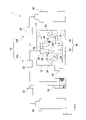
図1及び図2を参照して、実施形態に係る成形装置1について説明する。図1は、実施形態に係る成形装置1を示す概略正面図である。図2は、実施形態に係る第1吐出器36及び第2吐出器44によるエアロゾルS及び気体Gの吐出の様子を示す斜視図である。
A
[構成]
成形装置1は、無機材料から成る3次元成形体(成形体)を製造することができる。ここで、「無機材料」とは、有機材料以外の任意の材料を指し、金属単体、合金、金属元素及び非金属元素から成る化合物(例えば、金属酸化物や金属窒化物、金属塩など)、非金属元素から成る化合物(例えば、窒化ホウ素など)などが含まれる。ただし、成形装置1によって製造される3次元成形体は、有機材料をさらに含んでもよい。また、成形装置1を有機材料のみから成る3次元成形体の製造に利用することも可能である。
[Constitution]
The
図1に示すように、成形装置1は、ステージ10、チャンバ12、吐出装置14、監視部16、洗浄部18、及び制御部20(図9参照)を備える。
As shown in FIG. 1, the
図2に示すように、ステージ10は、水平面に沿って(すなわち、xy平面に対して平行に)配置された平板である。ステージ10の厚さ方向は、z方向に対して略平行である。ステージ10は、ステージ移動機構22(図1参照)により、少なくともz方向に移動可能である。ステージ移動機構22は、例えば、モーター(図示せず)により駆動するラックアンドピニオン式のアクチュエータである。ただし、ステージ10が鉛直方向など他の方向に対して平行に配置されてもよい。
As shown in FIG. 2, the
ステージ10は、粒子Pを固着させるための固着面10aを備えている。固着面10aは、上述のとおり、ステージ10自体の上面であってもよく、ステージ10に支持された基材の上面であってもよく、ステージ10又は基材に既に固着した粒子Pの表面であってもよい。基材の材料は特に限定されず、無機材料でもよく、有機材料でもよく、これらのハイブリッド材料でもよい。
The
図1に示すように、チャンバ12は、ステージ10、後述の吐出装置14の第1吐出器36及び第2吐出器44、並びに洗浄部18を収容する。チャンバ12の内部空間は、チャンバ12の外部空間と仕切られている。チャンバ12の内部空間は、チャンバ12に接続された真空ポンプ24により減圧され得る。チャンバ12の内部空間を真空引きすることにより、陰圧雰囲気下で成形作業を行うことが可能となり、不純物の混入などを抑制することができる。また、チャンバ12の内部空間が窒素ガスやアルゴンガスなどの不活性ガスで満たされてもよい。
As shown in FIG. 1 , the
吐出装置14は、エアロゾルSを発生させて吐出する第1吐出装置14aと気体Gを発生させて吐出する第2吐出装置14bとを備える。第1吐出装置14aは、第1ガスボンベ30、第1流量調節器32、エアロゾル発生器34、第2流量調節器35、第1吐出器36、及び第1吐出器移動機構38を備える。第2吐出装置14bは、第2ガスボンベ40、第3流量調節器42、第2吐出器44、及び第2吐出器移動機構46を備える。吐出装置14は、さらに、第1吐出装置14a及び第2吐出装置14bを制御する吐出制御部48(図9参照)を備える。
The
第1吐出装置14aは、エアロゾルSを発生させてステージ10に向けて吐出する。第1吐出装置14aの第1ガスボンベ30は、エアロゾルSを発生させるためのガスを収容している。ガスは、ヘリウムガスや窒素ガス、アルゴンガスなどの不活性ガスの他、空気や酸素ガス、水素ガス、有機ガスなど任意のガスであってよい。第1ガスボンベ30内のガスは、第1流量調節器32により調節された流量でエアロゾル発生器34に送られる。
The
第1流量調節器32は、第1ガスボンベ30からのガスの流量を調節できるものであれば、マスフローコントローラや簡易的な調圧弁など任意のものを使用可能である。第1流量調節器32は、吐出制御部48(図9参照)により制御される。
Any device such as a mass flow controller or a simple pressure regulating valve can be used as the
エアロゾル発生器34は、エアロゾルSのための粒子Pを収容している。エアロゾル発生器34は、第1ガスボンベ30からのガスを受け取る。ガスは、エアロゾル発生器34の内部で粒子Pと混合され、粒子Pが高圧ガスに分散したエアロゾルが形成される。形成されたエアロゾルは、エアロゾルSとしてエアロゾル発生器34から第2流量調節器35を介して第1吐出器36へ送られる。粒子Pの詳細については後述する。
The
なお、エアロゾル発生器34の構成は上記例に限定されない。例えば、粒子Pの分散液をガス中に噴霧して乾燥させることによりエアロゾルを発生させてもよく、分散液の噴霧には加圧噴霧の他、静電式噴霧や音波式噴霧、インクジェット技術などが利用可能である。その他、粒子Pがガス中に分散したエアロゾルが形成される限り、任意のエアロゾル発生器を使用することができる。
Note that the configuration of the
第2流量調節器35は、エアロゾル発生器34から第1吐出器36に供給されるエアロゾルSの流量を調節する。第1流量調節器32と同様に、ガスの流量を調節できるものであれば任意のものを使用可能である。第2流量調節器35は、吐出制御部48(図9参照)により制御される。なお、第2流量調節器35は、エアロゾル発生器34の構成要素として設けられてもよい。あるいは、第2流量調節器35を省略して、第1吐出器36に供給されるエアロゾルSの流量まで一括して第1流量調節器32で制御してもよい。
The second
第1吐出器36は、先端に開口を有する先細ノズルの形態である。第1吐出器36は、ステージ10から離間してステージ10の上方に配置されている。ただし、第1吐出器36の配置は上記例に限定されず、第1吐出器36がステージ10の下方や側方に配置されてもよい。第1吐出器36は、第1吐出器移動機構38により、x方向、y方向、及びz方向の少なくとも一方向に移動可能である。また、第1吐出器36は、第1吐出器移動機構38により、例えば、z軸に関して回動可能であり、z軸に平行な平面内でも回動可能である。第1吐出器移動機構38は、例えば、モーター(図示せず)により駆動する多関節アームである。
The
第1吐出器36は、エアロゾル発生器34から送られてきたエアロゾルSを、先端の開口からステージ10に向けて第1吐出速度V1で吐出する。第1吐出器36は、エアロゾルSを間欠的又は連続的に吐出することができる。第1吐出器36によるエアロゾルSの吐出速度は、第2流量調節器35により適宜調節可能である。ただし、吐出速度の調節は、チャンバ12とエアロゾル発生器34との間の圧力差を調節したり、図示しない駆動機構で第1吐出器36のノズル径や形状を切り替えたりすることにより行われてもよく、これらの方法が第2流量調節器35と併用されてもよい。なお、エアロゾルSの吐出速度は、例えば、チャンバ12内で第1吐出器36とステージ10との間に設けられた速度検出器(図示せず)により検出され得る。
The
なお、第1吐出装置14aは、エアロゾルS中の凝集した粒子Pを分散させるための解砕器や、所定の大きさを上回る粒子Pを分離するためのフィルタや分級器などを備えてもよい。
The
第2吐出装置14bは、気体Gを発生させてステージ10に向けて吐出する。第2吐出装置14bの第2ガスボンベ40は、気体Gのためのガスを収容している。ガスは、第1ガスボンベ30に収容されたガスと同様に、ヘリウムガスや窒素ガス、アルゴンガスなどの不活性ガスの他、空気や酸素ガス、水素ガス、有機ガスなど任意のガスであってよい。第2ガスボンベ40内のガスは、第3流量調節器42により調節された流量で第2吐出器44に送られる。
The
第3流量調節器42は、第1流量調節器32と同様に、第2ガスボンベ40からのガスの流量を調節できるものであれば任意のものを使用可能である。第3流量調節器42は、吐出制御部48(図9参照)により制御される。
As with the first
第2吐出器44は、先端に開口を有する先細ノズルの形態である。第2吐出器44は、ステージ10に対して第1吐出器36と同じ側に配置される。例えば、第2吐出器44は、第1吐出器36に対して並列するように配置される。第1吐出器36と同様に、第2吐出器44は、第2吐出器移動機構46により、x方向、y方向、及びz方向の少なくとも一方向に移動可能である。また、第2吐出器44は、第2吐出器移動機構46により、例えば、z軸に関して回動可能であり、z軸に平行な平面内でも回動可能である。第2吐出器移動機構46は、例えば、モーター(図示せず)により駆動する多関節アームである。
The
第2吐出器44は、第2ガスボンベ40から送られてきた気体Gを、先端の開口からステージ10に向けて第2吐出速度V2で吐出する。第2吐出器44は、気体Gを間欠的又は連続的に吐出することができる。第2吐出器44による気体Gの吐出速度は、エアロゾルSと同様に、第3流量調節器42により適宜調節可能である。また、上述のように、圧力差やノズル径の切り替えなどにより吐出速度を調節してもよい。また、エアロゾルSと同様に、気体Gの吐出速度も、例えば、チャンバ12内に設けられた速度検出器(図示せず)により検出され得る。
The
第2吐出速度V2は、第1吐出器36からエアロゾルSが吐出される第1吐出速度V1よりも速い。第2吐出器44は、気体Gが第1吐出器36から吐出されるエアロゾルSと少なくとも部分的に重なるように、気体Gをステージ10に向けて吐出する。エアロゾルS及び気体Gの吐出の詳細については後述する。
The second ejection speed V2 is faster than the first ejection speed V1 at which the aerosol S is ejected from the
監視部16は、ステージ10上の粒子Pの様子を監視する。監視部16は、例えば、ステージ10から離間してステージ10の上方に配置された撮像カメラを含む。この撮像カメラは、ステージ10の表面の様子を撮影し、監視部16は、撮影した画像に基づき、ステージ10上の粒子Pの位置や形状を検出する(この検出作業は、後述の制御部20が行ってもよい)。なお、監視部16の構成要素は撮像カメラに限定されず、放射線や超音波をステージ10上に照射することによりステージ面の様子を観察する放射線分析装置(例えばX線回折装置)や超音波分析装置などであってもよく、これらが併用されてもよい。
A
洗浄部18は、送気装置50及び回収装置52を備える。洗浄部18は、ステージ10上でステージ10に固着せずに残存している粒子Pや他の不純物などを除去することができる。
The
送気装置50は、気流をステージ10に吹き付けて、ステージ10に固着していない粒子Pなどを吹き飛ばす。送気装置50は、気流を発生させるものであれば任意の構成であってよい。例えば、ガス供給源(図示せず)から受け取ったガスをノズルから噴射するものであってもよく、扇風機のようにファンを回して気流を発生させるものであってもよい。送気装置50は、送気装置移動機構54により、少なくともx方向、y方向、及びz方向の少なくとも一方向に移動可能である。また、送気装置50は、送気装置移動機構54により、例えば、z軸に関して回動可能であり、z軸に平行な平面内でも回動可能である。送気装置移動機構54は、例えば、モーター(図示せず)により駆動する多関節アームである。ただし、送気装置50は固定されていてもよい。この場合、送気装置移動機構54は省略される。
The
回収装置52は、送気装置50により吹き飛ばされた粒子Pを吸い込んで回収する。回収装置52は、吸引機能を有するものであれば任意の構成であってよい。ただし、回収装置52は必ずしも吸引機能を有しなくてもよく、単に送気装置50により吹き飛ばされた粒子Pを回収するための開口を有する部材であってもよい。また、送気装置50が省略されて、固着していない粒子Pの除去が回収装置52の吸引のみにより行われてもよい。送気装置50と同様に、回収装置52は、回収装置移動機構56により、少なくともx方向、y方向、及びz方向の少なくとも一方向に移動可能である。また、回収装置52は、回収装置移動機構56により、例えば、z軸に関して回動可能であり、z軸に平行な平面内でも回動可能である。回収装置移動機構56は、例えば、モーター(図示せず)により駆動する多関節アームである。ただし、回収装置52は固定されていてもよい。この場合、回収装置移動機構56は省略される。
The
洗浄部18は、ステージ10の洗浄を行った後、監視部16により取得された情報からステージ10に固着していない粒子Pが残っていると判断された場合には、再び送気装置50及び回収装置52によりステージ10の洗浄を行うことができる。あるいは、洗浄部18は、定期的にステージ10の洗浄を行うように構成されてもよい。
After cleaning the
回収装置52は、回収した粒子Pを再びエアロゾル発生器34に戻してもよい。これにより、ステージ10に固着しなかった粒子PをエアロゾルSの原料として再利用することができる。
The
制御部20は、製造される成形体の3次元形状データなどの入力データを受け取り、成形装置1の各構成要素を制御する。制御部20は、例えばCPU(Central Processing Unit)又はGPU(Graphics Processing Unit)のようなプロセッサにより実現される。制御部20の動作については、図9及び図10を参照して後述する。
The
[エアロゾル材料]
第1吐出器36から吐出されるエアロゾルSは、第1ガスボンベ30から供給されたガスに粒子Pが分散したエアロゾルから構成される。
[Aerosol material]
The aerosol S ejected from the
粒子Pは、例えば金属、酸化物、窒化物、酸窒化物、炭化物、水酸化物、炭酸化物、燐酸化物など任意の無機材料、任意の有機材料、又はこれらの組合せから成る粒子である。粒子Pの材料は特に限定されない。
金属の例としては、アルミニウム、チタン、鉄、銅、ステンレス鋼、ニッケルクロム鋼などが挙げられる。
酸化物の例としては、二酸化ケイ素、酸化アルミニウム、酸化マグネシウム、酸化チタン、酸化鉄、酸化亜鉛、酸化イットリウム、酸化ジルコニウム、チタン酸バリウム、チタン酸ジルコン酸鉛などが挙げられる。
窒化物の例としては、窒化ケイ素、窒化アルミニウム、窒化チタン、窒化鉄などが挙げられる。
酸窒化物の例としては、酸窒化ケイ素、酸窒化アルミニウムなどが挙げられる。
炭化物の例としては、炭化ケイ素、炭化チタン、炭化ホウ素、炭化ジルコニウムなどが挙げられる。
水酸化物の例としては、水酸マグネシウム、水酸化鉄、水酸アパタイトなどが挙げられる。
炭酸化物の例としては、炭酸カルシウム、炭酸ナトリウム、炭酸カリウム、炭酸リチウムなどが挙げられる。
燐酸化物の例としては、燐酸鉄、燐酸マンガン、燐酸カルシウムなどが挙げられる。
有機材料の例としては、ポリエチレンやポリエチレンテレフタレート(PET)などの炭化水素、ポリスチレンやポリイミドなどのエンジニアプラスチック、ポリテトラフルオロエチレン(PTFE)やポリフッ化ビニリデン(PVdF)などのフッ素系ポリマー、タンパク質、脂肪などの生体高分子などが挙げられる。
Particles P are particles of any inorganic material, such as metals, oxides, nitrides, oxynitrides, carbides, hydroxides, carbonates, phosphorous oxides, etc., any organic material, or combinations thereof. The material of the particles P is not particularly limited.
Examples of metals include aluminum, titanium, iron, copper, stainless steel, nickel-chromium steel, and the like.
Examples of oxides include silicon dioxide, aluminum oxide, magnesium oxide, titanium oxide, iron oxide, zinc oxide, yttrium oxide, zirconium oxide, barium titanate, lead zirconate titanate, and the like.
Examples of nitrides include silicon nitride, aluminum nitride, titanium nitride, iron nitride, and the like.
Examples of oxynitrides include silicon oxynitride, aluminum oxynitride, and the like.
Examples of carbides include silicon carbide, titanium carbide, boron carbide, zirconium carbide, and the like.
Examples of hydroxides include magnesium hydroxide, iron hydroxide, hydroxyapatite, and the like.
Examples of carbonates include calcium carbonate, sodium carbonate, potassium carbonate, lithium carbonate, and the like.
Examples of phosphorous oxides include iron phosphate, manganese phosphate, calcium phosphate, and the like.
Examples of organic materials include hydrocarbons such as polyethylene and polyethylene terephthalate (PET), engineering plastics such as polystyrene and polyimide, fluoropolymers such as polytetrafluoroethylene (PTFE) and polyvinylidene fluoride (PVdF), proteins, and fats. Examples include biopolymers such as
[吐出装置の作用]
図2~図5を参照して、実施形態における吐出装置14の作用について説明する。
図2は、実施形態に係る第1吐出器36及び第2吐出器44によるエアロゾルS及び気体Gの吐出の様子を示す斜視図である。
[Action of discharge device]
The operation of the
FIG. 2 is a perspective view showing how the aerosol S and the gas G are ejected by the
図2に示すように、気体Gは、第1吐出器36から吐出されるエアロゾルSと少なくとも部分的に重なるように、エアロゾルSが吐出される第1吐出速度V1より速い第2吐出速度V2で第2吐出器44から吐出される。これにより、エアロゾルSのうち気体Gと重なった部分は、気体Gにより、エアロゾルSの他の部分に比べてステージ10に向かって加速する。その結果、第1吐出器36の吐出領域R1と第2吐出器44の吐出領域R2との重畳部分である第1部分61には、気体Gにより加速されたエアロゾルSが衝突する。第1吐出器36の吐出領域R1のうち第2吐出器44の吐出領域R2と重ならない部分である第2部分62には、気体Gにより加速されていないエアロゾルSが衝突する。第2吐出器44の吐出領域R2のうち第1吐出器36の吐出領域R1と重ならない部分である第3部分63には、実質的にエアロゾルSが衝突しない。ここで、「吐出領域」とは、仮想的に第1吐出器36又は第2吐出器44からステージ10に向けてエアロゾルSを吐出した場合に、エアロゾルS中の粒子Pの大部分(例えば95%)が着地する領域を意味する。
As shown in FIG. 2, the gas G is discharged at a second discharge speed V2, which is faster than the first discharge speed V1 at which the aerosol S is discharged, so as to at least partially overlap the aerosol S discharged from the
第1吐出速度V1は、粒子Pを含むエアロゾルSが第1吐出器36からステージ10に向けて第1吐出速度V1で吐出された場合に、粒子Pがステージ10に実質的に固着しないような速度に設定することができる。一方、第2吐出速度V2は、粒子Pを含むエアロゾルSが第1吐出器36からステージ10に向けて第2吐出速度V2で吐出された場合に、粒子Pがステージ10に実質的に固着するような速度に設定することができる。言い換えると、エアロゾルSがある閾値(本明細書において「臨界速度」という。)以上の吐出速度で吐出された場合にエアロゾルS中の粒子Pがステージ10に実質的に固着し、第1吐出速度V1は臨界速度未満であり、第2吐出速度V2は臨界速度以上である。ここで、臨界速度は、粒子Pの種類や大きさ、ステージ10や基材の材料などに依存する。例えば、平均粒径が約0.4μmのα-Al2O3の粒子Pを含み、窒素ガスをキャリアガスとするエアロゾルSを用いて、3mmのノズル径を有する第1吐出器36から5cmだけ離れた銅製の基材へ粒子Pの固着を行った場合、臨界速度は150m/s程度である。この場合、第1吐出速度V1は、例えば20m/s~100m/s、好ましくは50m/s~80m/sであり、第2吐出速度V2は、例えば200m/s~1000m/s、好ましくは400m/s~800m/sである。例えば、第1吐出速度V1は60m/sであり、第2吐出速度V2は500m/sである。
The first ejection speed V1 is set so that the particles P do not substantially adhere to the
このように第1吐出速度V1及び第2吐出速度V2を設定することにより、吐出されたエアロゾルSのうち気体Gと重なった部分に含まれる粒子Pのみをステージ10に実質的に固着させることが可能となる。これについて、図3~図5を参照してさらに説明する。
By setting the first ejection speed V1 and the second ejection speed V2 in this manner, it is possible to substantially adhere only the particles P contained in the portion of the ejected aerosol S overlapping the gas G to the
図3は、仮想的に第2吐出器44を用いずに第1吐出器36からエアロゾルSを第1吐出速度V1で吐出した場合の、実施形態に係る成形装置1の動作を示す図である。
FIG. 3 is a diagram showing the operation of the
図3(a)では、エアロゾルSが第1吐出器36からステージ10上の固着面10aに向けて第1吐出速度V1で吐出される。エアロゾルSは、第1吐出器36の先端から一定の広がりを持って吐出される。第1吐出器36の中心軸36aに近いほど、エアロゾルSの濃度(ひいては粒子Pの濃度)が大きく、粒子Pが密に存在する。
In FIG. 3A, the aerosol S is discharged from the
図3(b)では、吐出されたエアロゾルS中の粒子Pが固着面10a上に着地している。上述のとおり、第1吐出速度V1で吐出されたエアロゾルS中の粒子Pは固着面10aに実質的に固着しないので、固着面10a上の粒子Pはいずれも固着面10aに固着していない非固着粒子NPとなる。
In FIG. 3B, the particles P in the discharged aerosol S land on the fixing
図3(c)では、送気装置50からの気流により固着面10a上の非固着粒子NPが吹き飛ばされて、回収装置52により回収される。これにより、実質的にすべての粒子Pが固着面10aから除去される。
In FIG. 3C , the non-adhered particles NP on the adhering
図3(d)は、送気装置50の操作後にステージ10を上から見た平面図である。実質的にすべての粒子Pが除去されるので、第1吐出器36の吐出領域R1及び第2吐出器44の吐出領域R2のいずれにも粒子Pは実質的に残っていない。
FIG. 3D is a top plan view of the
図4は、仮想的に第2吐出器44を用いずに第1吐出器36からエアロゾルSを第2吐出速度V2で吐出した場合の、実施形態に係る成形装置1の動作を示す図である。なお、本明細書で説明する実施形態では、第2吐出器44を併用する場合、第1吐出器36は、エアロゾルSを第2吐出速度V2ではなく第1吐出速度V1で吐出する。
FIG. 4 is a diagram showing the operation of the
図4(a)では、エアロゾルSが第1吐出器36からステージ10上の固着面10aに向けて第2吐出速度V2で吐出される。
In FIG. 4A, the aerosol S is discharged from the
図4(b)では、吐出されたエアロゾルS中の粒子Pが固着面10a上に着地している。上述のとおり、第2吐出速度V2で吐出されたエアロゾルS中の粒子Pは固着面10aに実質的に固着するので、固着面10a上の粒子Pはいずれも固着面10aに固着した固着粒子FPとなる。
In FIG. 4B, the particles P in the discharged aerosol S land on the fixing
図4(c)では、送気装置50から固着面10aに気流が吹き付けられるが、固着面10a上の粒子Pはいずれも固着面10aに実質的に固着しているので、固着面10aから除去されない。
In FIG. 4(c), airflow is blown from the
図4(d)は、送気装置50の操作後にステージ10を上から見た平面図である。実質的にすべての粒子Pが固着面10aから除去されないので、第1吐出器36の吐出領域R1全体にわたって固着粒子FPが残っている。
FIG. 4(d) is a plan view of the
図5は、第1吐出器36からエアロゾルSを第1吐出速度V1で吐出するとともに第2吐出器44から気体Gを第2吐出速度V2で吐出した場合の、実施形態に係る成形装置1の動作を示す図である。これが、本明細書で説明する実施形態の実際の動作の一例に相当する。
FIG. 5 shows the
図5(a)では、エアロゾルSが第1吐出器36からステージ10上の固着面10aに向けて第1吐出速度V1で吐出され、気体Gが第2吐出器44から固着面10aに向けて第2吐出速度V2で吐出される。ここで、エアロゾルSと気体Gとが重なる領域においては、より勢いのある気体Gにより、エアロゾルSがステージ10に向かって加速する。
In FIG. 5A, the aerosol S is discharged from the
図5(b)では、吐出されたエアロゾルS中の粒子Pが固着面10a上に着地している。上述のとおり、気体Gは第2吐出速度V2で吐出されるので、吐出されたエアロゾルSのうち気体Gと重なる部分が気体Gにより十分に加速すると、当該部分に含まれる粒子Pは、固着面10aに衝突して固着面10aに実質的に固着する。このため、第1吐出器36の吐出領域R1と第2吐出器44の吐出領域R2との重畳部分である第1部分61(図2参照)においては、固着面10a上の粒子Pはいずれも固着面10aに固着した固着粒子FPである。
In FIG. 5B, the particles P in the discharged aerosol S land on the fixing
一方、エアロゾルSは第1吐出速度V1で吐出されるので、吐出されたエアロゾルSのうち気体Gと重ならない部分に含まれる粒子Pは、固着面10aに衝突しても固着面10aに実質的に固着しない。このため、第1吐出器36の吐出領域R1のうち第2吐出器44の吐出領域R2と重ならない部分である第2部分62(図2参照)においては、固着面10a上の粒子Pはいずれも固着面10aに固着していない非固着粒子NPである。
On the other hand, since the aerosol S is ejected at the first ejection speed V1, the particles P contained in the portions of the ejected aerosol S that do not overlap with the gas G substantially adhere to the fixing
図5(c)では、送気装置50からの気流により固着面10a上の非固着粒子NPが吹き飛ばされて、回収装置52により回収される。一方、第1部分61に存在する固着粒子FPは、送気装置50によって吹き飛ばされずに固着面10a上に残る。
In FIG. 5C, the non-adhered particles NP on the adhering
図5(d)は、送気装置50の操作後にステージ10を上から見た平面図である。結果として、実質的に第1部分61のみに固着粒子FPが残り、それ以外の部分には実質的に固着粒子FPも非固着粒子NPも残らないことになる。仮に偶発的に第2部分62にも多少の粒子Pが固着したとしても、第1部分61は、固着粒子FPに覆われる割合が第2部分62よりも格段に大きくなる。すなわち、固着粒子FPが第1部分61を覆う面積と第1部分61全体の面積との比により定義される第1部分61のカバー率は、固着粒子FPが第2部分62を覆う面積と第2部分62全体の面積との比により定義される第2部分62のカバー率よりも格段に大きい。
FIG. 5(d) is a plan view of the
なお、図5(d)では、図4(d)に比べてより多くの固着粒子FPが第1部分61に固着しているが、これは、例えば、図5に示すケースでは、図4に示すケースよりも長時間にわたってエアロゾルS及び気体Gの吐出を行うことにより実現される。図5に示すケースでは、図4に示すケースとは異なり、第2部分62の非固着粒子NPを監視部16により除去することができるので、図4よりも長時間にわたって吐出操作を行った後で非固着粒子NPを除去することにより、図4(d)における第1吐出器36の吐出領域R1の中心部と同程度又はそれ以上に多くの粒子Pを第1部分61に集中的に固着させることが可能である。
In FIG. 5(d), more fixed particles FP are fixed to the
なお、第2吐出器44の吐出領域R2のうち第1吐出器36の吐出領域R1と重ならない部分である第3部分63には、そもそもエアロゾルSが供給されないので、吐出操作後、第3部分63には実質的に粒子Pが残らない。
Note that since the aerosol S is not originally supplied to the
このように、第1吐出速度V1を臨界速度未満に設定するとともに第2吐出速度V2を臨界速度以上に設定することにより、エアロゾルSのうち気体Gと重なる部分のみを臨界速度以上に加速させて、当該部分に含まれる粒子Pのみを固着面10aに固着させることができる。
By setting the first discharge speed V1 to be less than the critical speed and the second discharge speed V2 to be equal to or higher than the critical speed in this manner, only the portion of the aerosol S that overlaps the gas G is accelerated to the critical speed or higher. , only the particles P contained in the portion can be fixed to the fixing
なお、第1吐出器移動機構38及び第2吐出器移動機構46により第1吐出器36及び第2吐出器44の配置を適宜調節することにより、ステージ10上における第1部分61の位置や大きさ、形状を必要に応じて調節することができる。
By appropriately adjusting the arrangement of the
例えば、図6に示すように、第2吐出器44が第1吐出器36に近づくように第2吐出器移動機構46により第2吐出器44をx方向に移動させると、第1吐出器36の吐出領域R1と第2吐出器44の吐出領域R2との重畳部分である第1部分61が大きくなり、より大面積にわたって粒子Pを一度に固着させることができる。逆に、粒子Pを固着させる面積を小さくする場合には、第2吐出器44が第1吐出器36から離れるように第2吐出器移動機構46により第2吐出器44を移動させればよい。
For example, as shown in FIG. 6, when the
また、例えば、図7に示すように、第2吐出器44がステージ10から離れるように第2吐出器移動機構46により第2吐出器44をz方向(例えば上方向)に移動させると、第2吐出器44の吐出領域R2が大きくなることにより第1部分61も大きくなるので、より大面積にわたって粒子Pを一度に固着させることができる。逆に、第2吐出器44がステージ10に近づくように第2吐出器移動機構46により第2吐出器44をz方向(例えば下方向)に移動させると、第2吐出器44の吐出領域R2を小さくすることができ、より小さな領域に対して粒子Pの固着を行うことができる。
Further, for example, as shown in FIG. 7, when the
さらに、図8に示すように、第2吐出器44が気体Gを吐出する方向がステージ10の法線方向に対して傾くように第2吐出器移動機構46により第2吐出器44をy軸に関して回動させた場合も、第1部分61を大きくしたり小さくしたりすることができるので、粒子Pが固着する面積を変化させることができる。
Further, as shown in FIG. 8, the
[システム構成]
次に、図9を参照して、成形装置1のシステム構成について説明する。
図9は、実施形態に係る成形装置1のシステム構成の一例を示すブロック図である。
[System configuration]
Next, a system configuration of the
FIG. 9 is a block diagram showing an example of the system configuration of the
入力部70は、製造予定の成形体の入力データ(例えば、成形体の3次元構造データ)を受け付けるとともに、当該入力データを制御部20に送信する。
The
監視部16は、ステージ10上の粒子Pの監視データを取得するとともに、当該監視データを制御部20に送信する。監視データには、ステージ10の固着粒子FPや非固着粒子NPの位置や形状などが含まれる。
The
制御部20は、入力部70から受け付けた入力データ及び監視部16から取得した監視データなどに基づき、ステージ10が適切な位置に移動するように、ステージ移動機構22を制御するとともに、送気装置50及び回収装置52が適切な配置となるように、送気装置移動機構54及び回収装置移動機構56をそれぞれ制御する。また、制御部20は、ユーザの入力などに応じて、チャンバ12の内部空間の真空引きを開始、調節、又は停止するように真空ポンプ24を制御する。
Based on the input data received from the
制御部20は、吐出装置14の制御を行う吐出制御部48を備える。吐出制御部48は、入力データ及び監視データなどに基づき、第1吐出装置14a及び第2吐出装置14bをそれぞれ制御する。具体的には、吐出制御部48は、エアロゾルSを適切な量や濃度、適切なタイミングで第1吐出器36に供給するように第1流量調節器32、エアロゾル発生器34、及び第2流量調節器35を制御するとともに、エアロゾルSを適切な速度かつ適切なタイミングで吐出するように第1吐出器36を制御する。また、吐出制御部48は、気体Gを適切な量かつ適切なタイミングで第2吐出器44に供給するように第3流量調節器42を制御するとともに、気体Gを適切な速度かつ適切なタイミングで吐出するように第2吐出器44を制御する。さらに、吐出制御部48は、第1吐出器36及び第2吐出器44が適切な配置となるように、第1吐出器移動機構38及び第2吐出器移動機構46をそれぞれ制御する。
The
[成形体の製造方法]
次いで、図10を参照して、成形装置1による成形体の製造方法について説明する。
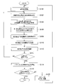
図10は、実施形態に係る成形装置1による成形体の製造方法の一例を示すフローチャートである。
[Method for manufacturing compact]
Next, with reference to FIG. 10, a method for manufacturing a molded article by the
FIG. 10 is a flow chart showing an example of a method for manufacturing a molded article by the
ステージ10上で第1層の形成が開始される(S100)と、まず、制御部20は、入力データに基づき、ステージ10上の粒子Pを固着させる固着予定位置(上記の第1部分61に相当する)を決定するとともに、当該固着予定位置に粒子Pを固着させるためにエアロゾルS及び気体Gがそれぞれ吐出される二つの吐出領域(上記の第1吐出器36の吐出領域R1及び第2吐出器44の吐出領域R2に相当する)を決定する(S102)。
When the formation of the first layer on the
次いで、制御部20は、決定された固着予定位置及び各吐出領域に基づき、必要に応じて第1吐出器36、第2吐出器44、送気装置50、及び回収装置52を移動させてそれらの位置や角度を変更するように、第1吐出器移動機構38、第2吐出器移動機構46、送気装置移動機構54、及び回収装置移動機構56にそれぞれ指示する(S104)。
Next, the
次いで、制御部20は、第1吐出器36の吐出領域に向けてエアロゾルSを吐出するように第1吐出器36に指示するとともに、第2吐出器44の吐出領域に向けて気体Gを吐出するように第2吐出器44に指示する(S106)。ここで、制御部20は、予め決定された臨界速度に基づき、第2流量調節器35に指示して、第1吐出器36の吐出速度が臨界速度未満の第1吐出速度V1となるように、第1吐出器36に供給されるエアロゾルSの流量を調節させるとともに、第3流量調節器42に指示して、第2吐出器44の吐出速度が臨界速度以上である第2吐出速度V2となるように、第2吐出器44に供給される気体Gの流量を調節させる。上述のとおり、吐出されたエアロゾルSのうち気体Gと重なる部分が気体Gにより加速し、この部分に含まれる粒子Pのみがステージ10に固着する。なお、第1吐出器36の吐出タイミングと第2吐出器44の吐出タイミングとは同時であってもよく、時間差があってもよい。
Next, the
次いで、制御部20は、ステージ10に気流を吹き付けて非固着粒子NPをステージ10から吹き飛ばすように送気装置50に指示する(S108)。また、制御部20は、送気装置50により吹き飛ばされた非固着粒子NPを回収するように回収装置52に指示する(S110)。なお、制御部20は、このタイミングで、送気装置50及び回収装置52を移動させるように送気装置移動機構54及び回収装置移動機構56に指示してもよい。
Next, the
次いで、制御部20は、ステージ10に固着した固着粒子FPの情報を取得するように監視部16に指示する(S112)。例えば、制御部20は、撮像カメラで上から見たステージ10の画像を撮影するように監視部16に指示する。制御部20は、監視部16が取得した画像などに基づき、ステージ10上の固着粒子FPの位置や形状を確認する。例えば、制御部20は、固着粒子FPが固着予定位置に適切に固着しているか、固着予定位置以外の位置に固着粒子FPが固着していないか、固着予定位置に固着した固着粒子FPの量は適切か、固着粒子FPにクラックなどが生じていないか、などを判定する。
Next, the
次いで、制御部20は、入力データに照らして、第1層の形成が完了したか否かを判定する(S114)。例えば、制御部20は、それまでの動作履歴を参照して、入力データにおける第1層の固着予定位置のうちまだ固着操作を行っていないものがあるか否かを判定し、まだ固着操作を行っていない固着予定位置があると判定された場合には、制御部20は、第1層の形成が完了していないと判定する。第1層の全固着予定位置に対して固着操作を行ったと判定された場合には、制御部20は、第1層の形成が完了したと判定する。あるいは、制御部20は、入力データと監視部16により取得された実際のステージ10上の様子との比較対照を行い、入力データにおいて第1層で粒子Pの固着が行われるべき全位置と、実際にステージ10上で粒子Pが固着している全位置との一致の程度を計算してもよい。この場合、入力データにおける固着予定位置と監視部16により得られた実際の固着位置とが十分に一致していると判定された場合、制御部20は、第1層の形成が完了したと判定する。
Next, the
第1層の形成が完了していないと判定された場合(S114:NO)、制御部20は、S102に戻り、上記の判定結果に基づき、次の固着予定位置及び吐出領域を決定する。例えば、固着粒子FPが固着予定位置に適切に固着したと判定された場合には、制御部20は、入力データに照らして、第1層内の次の固着予定位置及び吐出領域を決定する。例えば、固着予定位置に固着した固着粒子FPの量が不十分であると判定された場合には、制御部20は、固着予定位置を変更せず又は僅かに変更して、再度吐出を行うように第1吐出器36及び第2吐出器44に指示する。
If it is determined that the formation of the first layer has not been completed (S114: NO), the
ここで、次の固着予定位置は、任意の方法で決定される。例えば、次の固着予定位置は、まずx方向に沿ってステージ10の一端から他端へ進み、その後y方向に僅かに進み、再びx方向に沿ってステージ10の一端から他端へ進み、再びy方向に僅かに進み、……、という順序に従って決定されてもよく、直前の固着位置からの距離に基づいて(例えば、直前の固着位置に最も近い固着予定位置が次の固着予定位置に設定されるように)決定されてもよい。
Here, the next fixation planned position is determined by an arbitrary method. For example, the next fixation position is first to advance from one end of the
なお、成形装置1は、入力データにおける固着予定位置とは異なる位置に粒子Pが固着してしまった場合に当該粒子Pをステージ10から除去するための固着粒子除去手段(図示せず)を備えてもよい。固着粒子除去手段は、例えば、ステージ10に固着した粒子Pを物理的に削り取る、位置制御可能な切削装置である。
The
一方、第1層の形成が完了したと判定された場合(S114:YES)には、制御部20は、エアロゾルS及び気体Gの吐出を停止するように第1吐出器36及び第2吐出器44に指示する(S116)。
On the other hand, when it is determined that the formation of the first layer has been completed (S114: YES), the
次に、制御部20は、入力データに照らして、成形体全体の形成が完了したか否かを判定する(S118)。例えば、制御部20は、それまでの動作履歴を参照して、入力データにおける各層の全固着予定位置のうちまだ固着操作を行っていないものがあるか否かを判定し、まだ固着操作を行っていない固着予定位置があると判定された場合には、制御部20は、成形体全体の形成が完了していないと判定する。成形体の形成が完成していないと判定された場合(S118:NO)、制御部20は、ステージ10をz方向に移動させる(例えば、z方向に1層分だけ下降させる)ようにステージ移動機構22に指示する(S120)。その後、フローはS100に戻り、第2層の形成が開始される。
Next, the
一方、成形体全体の形成が完了したと判定された場合(S118:YES)、成形体の製造が完了する。第1層から最終層まで形成が完了することにより、任意の3次元立体形状を有する成形体が得られる。 On the other hand, if it is determined that the formation of the entire compact has been completed (S118: YES), the production of the compact is completed. By completing the formation from the first layer to the final layer, a molded body having an arbitrary three-dimensional shape can be obtained.
[効果]
以上説明した成形装置1によれば、吐出器から吐出されたエアロゾルの分布のうち一部の小領域のみをステージに固着させることができる。これにより、単に吐出器でエアロゾルを高速噴射することにより粒子固着を行う場合に比べて、格段に小さな領域での粒子固着が可能となる。すなわち、粒子の固着位置の分解能及び選択性、ひいては位置制御性が向上する。このような小領域への粒子固着を繰り返すことにより、バインダーの使用や加熱処理を必要とせずに、3次元造形体の精密な成形を行うことができるようになる。
[effect]
According to the
バインダーを使用しないので、バインダーの光硬化工程や脱脂工程が不要となる。また、常温での固着が可能であるので、焼結工程も不要であり、加熱による材料の変質や損傷を抑制することができる。さらに、脱脂工程や焼結工程などの加熱工程が不要であるので、成形作業の全工程を常温で実施することができ、加熱装置などが不要になる。このため、作業が格段に容易かつ低コストとなり得る。 Since no binder is used, the photo-curing process and degreasing process of the binder are not required. In addition, since it can be fixed at room temperature, a sintering process is not necessary, and deterioration and damage of the material due to heating can be suppressed. Furthermore, since heating processes such as a degreasing process and a sintering process are not required, all the molding processes can be performed at room temperature, and a heating device or the like is not required. This can make the work much easier and less costly.
本実施形態によると、成形装置1の吐出装置14は、第1吐出器36の位置及び向きの少なくとも一方を変更する第1吐出器移動機構38と、第2吐出器44の位置及び向きの少なくとも一方を変更する第2吐出器移動機構46と、をさらに備え、第1吐出器移動機構38及び第2吐出器移動機構46は、第1吐出器36と第2吐出器44との間の距離及び第1吐出器36がエアロゾルSを吐出する方向と第2吐出器44が気体Gを吐出する方向とのなす角の少なくとも一方を変更することができる。このような構成によれば、粒子Pが固着する領域(すなわち第1部分61)の大きさや形状を必要に応じて変更することができる。これにより、粒子Pの固着位置の選択性が向上し、ひいては成形装置1による3次元造形の自由度が向上する。
According to this embodiment, the
本実施形態によると、成形装置1は、固着面10a上の粒子Pを監視する監視部16をさらに備え、制御部20は、監視部16からの情報に基づき、エアロゾルSが吐出される固着面10a上の領域R1及び気体Gが吐出される固着面10a上の領域R2の少なくとも一方を決定する。このような構成によれば、実際にステージ10に固着した粒子Pの位置や形状に基づき、次の固着予定位置を決定することができるので、より精密な造形が可能となる。また、吐出されたエアロゾルSの分布にはある程度のランダム性が存在するところ、上述のようなフィードバック制御により、このようなランダム性を補償することができる。
According to this embodiment, the
本実施形態によると、成形装置1は、固着していない粒子Pを固着面10aから除去する洗浄部18をさらに備え、洗浄部18は、固着していない粒子Pを固着面10aから吹き飛ばす送気装置50及び固着していない粒子Pを固着面10aから回収する回収装置52を有する。このような構成によれば、非固着粒子NPを除去するだけでなく、その後に吐出されるエアロゾルSの原料として再利用することが可能となるので、成形作業のコストを低減することができる。
According to this embodiment, the
[変形例]
上記例では、エアロゾルSと気体Gとを併用することで粒子Pを小さなスポットに固着させることを繰り返して成形体を形成しているが、成形工程中にある程度の大面積又は層全体に粒子Pを固着させることが必要となった場合には、第2吐出器44からの気体Gの供給を一旦停止し、第1吐出器36からエアロゾルSを臨界速度以上の第2吐出速度V2で吐出させることにより、大面積に対して一度に粒子Pを固着させることもできる。すなわち、第1吐出器36の吐出速度及び第2吐出器44の使用の有無を必要に応じて切り替えることにより、小面積への固着と大面積への固着とを状況に応じて使い分けることができる。
[Modification]
In the above example, the aerosol S and the gas G are used in combination to repeatedly adhere the particles P to small spots to form the compact. When it becomes necessary to fix the aerosol S, the supply of the gas G from the
上記例では、エアロゾルSと気体Gとが同程度の広がりをもって吐出されているが、図11のように第2吐出器44から吐出される気体Gの広がりを第1吐出器36よりも絞ってもよい。この場合も、上記例と同様に、エアロゾルSのうち気体Gと重なる部分のみが加速し、エアロゾルSの吐出領域R1と気体Gの吐出領域R2とが重なる第1部分61においてのみ、エアロゾルS中の粒子Pがステージ10に固着することになる。エアロゾルSの吐出領域R1のうち気体Gの吐出領域R2と重ならない第2部分62における非固着粒子NPは、洗浄部18により除去される。
In the above example, the aerosol S and the gas G are discharged with the same degree of spread, but as shown in FIG. good too. In this case, as in the above example, only the portion of the aerosol S that overlaps with the gas G is accelerated, and only in the
上記例では、第1吐出装置14aを用いて1種類の粒子Pを含むエアロゾルSが吐出されるが、2種類以上の粒子Pが用いられてもよい。例えば、粒子Pとは別の材料の粒子を含むエアロゾルを吐出するために、第1吐出装置14aと同様の別の吐出装置がさらに設けられてもよい。また、切替弁などを利用することにより、第1吐出装置14aが、状況に応じて異なるエアロゾルを吐出できるように構成されてもよい。
In the above example, the aerosol S containing one type of particles P is discharged using the
上記例では、円形の開口を有するノズルが用いられているが、第1吐出器36及び第2吐出器44の構成はこれに限定されない。例えば、第1吐出器36及び第2吐出器44は、y方向に延在する矩形又は楕円形の開口を有してもよい。この場合、第1部分61がy方向に長く形成され得るので、成形作業の効率が向上し得る。このような吐出器でy方向に小さな領域に固着を行う場合には、例えば第1部分61がy方向に短くなるように第2吐出器44を第1吐出器36に対してy方向にずらせばよい。
Although a nozzle having a circular opening is used in the above example, the configuration of the
また、複数の第1吐出器36及び複数の第2吐出器44が設けられてもよい。例えば、複数の第1吐出器36及び複数の第2吐出器44をアレイ状に配置し、それぞれ個別に吐出の制御を行うことにより、同時に複数の位置に対して粒子Pの固着を行うことが可能となる。
Also, multiple
上記例では、洗浄部18は、送気装置50及び回収装置52によりステージ10に固着していない粒子P(すなわち非固着粒子NP)を除去するものであるが、それに加えて又はその代わりに、気流による除去以外の機構も利用可能である。例えば、洗浄部18は、非固着粒子NPを物理的に直接掃き取る機構を有してもよく、非固着粒子NPがくっつく接着性部材を有してもよい。粒子Pが磁性粒子である場合には、洗浄部18は、磁力により非固着粒子NPを除去する機構を有してもよい。また、これらが併用されてもよい。
In the above example, the
以上のように、本発明を限定された実施例と図面によって説明したが、本発明はこれに限定されるものではなく、本発明の属する技術分野で通常の知識を持つ者によって本発明の技術思想と特許請求の範囲の均等範囲内で多様な修正及び変形が可能であることは言うまでもない。 As described above, the present invention has been described with limited examples and drawings, but the present invention is not limited thereto, and the technical knowledge of the present invention can be obtained by a person having ordinary knowledge in the technical field to which the present invention belongs. It goes without saying that various modifications and variations are possible within the equivalent scope of the concept and claims.
1 成形装置
10 ステージ
10a 固着面
12 チャンバ
14 吐出装置
14a 第1吐出装置
14b 第2吐出装置
16 監視部
18 洗浄部
20 制御部
22 ステージ移動機構
24 真空ポンプ
30 第1ガスボンベ
32 第1流量調節器
34 エアロゾル発生器
35 第2流量調節器
36 第1吐出器
38 第1吐出器移動機構
40 第2ガスボンベ
42 第3流量調節器
44 第2吐出器
46 第2吐出器移動機構
48 吐出制御部
50 送気装置
52 回収装置
54 送気装置移動機構
56 回収装置移動機構
61 第1部分
62 第2部分
63 第3部分
70 入力部
Claims (15)
前記粒子を含むエアロゾルを第1吐出速度で前記固着面に向けて吐出する第1吐出器と、
気体を前記第1吐出速度より速い第2吐出速度で前記固着面に向けて吐出する第2吐出器と、を備え、
前記第2吐出器は、前記気体が前記エアロゾルと少なくとも部分的に重なることにより前記エアロゾルの少なくとも一部を前記固着面に向けて加速させて前記粒子を前記固着面に固着させるように前記気体を吐出する、吐出装置。 A discharge device used for causing particles to collide with and adhere to a fixing surface,
a first ejector that ejects the aerosol containing the particles toward the fixing surface at a first ejection speed;
a second ejector that ejects gas toward the fixing surface at a second ejection speed higher than the first ejection speed;
The second ejector expels the gas such that the gas at least partially overlaps the aerosol, thereby accelerating at least a portion of the aerosol toward the sticking surface and causing the particles to stick to the sticking surface. An ejection device that ejects.
前記第2吐出速度は、前記第2吐出速度で吐出された前記エアロゾルが前記固着面に衝突した場合に前記粒子が前記固着面に実質的に固着するような速度である、請求項1に記載の吐出装置。 The first ejection speed is a speed at which the particles do not substantially stick to the fixing surface when the aerosol ejected at the first ejection speed collides with the fixing surface;
2. The method according to claim 1, wherein the second ejection speed is such that when the aerosol ejected at the second ejection speed collides with the fixing surface, the particles are substantially fixed to the fixing surface. discharge device.
前記第1吐出速度は、前記粒子の前記臨界速度未満であり、
前記第2吐出速度は、前記粒子の前記臨界速度以上である、請求項1又は2に記載の吐出装置。 the particles substantially stick to the sticking surface when the aerosol is ejected at a velocity equal to or higher than a critical velocity and collides with the sticking surface;
wherein the first ejection velocity is less than the critical velocity of the particles;
3. The ejection device according to claim 1, wherein said second ejection speed is equal to or higher than said critical speed of said particles.
前記第2吐出器の位置及び向きの少なくとも一方を変更する第2吐出器移動機構と、
をさらに備え、
前記第1吐出器移動機構及び前記第2吐出器移動機構は、前記第1吐出器と前記第2吐出器との間の距離及び前記第1吐出器が前記エアロゾルを吐出する方向と前記第2吐出器が前記気体を吐出する方向とのなす角の少なくとも一方を変更することができる、請求項1~5のいずれか一項に記載の吐出装置。 a first dispenser moving mechanism for changing at least one of the position and orientation of the first dispenser;
a second dispenser moving mechanism for changing at least one of the position and orientation of the second dispenser;
further comprising
The first ejector moving mechanism and the second ejector moving mechanism are configured to control the distance between the first ejector and the second ejector, the direction in which the first ejector ejects the aerosol, and the second ejector. The ejection device according to any one of claims 1 to 5, wherein at least one of the angles formed by the ejector with the direction in which the gas is ejected can be changed.
請求項1~6のいずれか一項に記載の吐出装置と、
を備える成形装置。 a stage having a fixation surface;
a discharge device according to any one of claims 1 to 6;
A molding device comprising:
前記制御部は、前記監視部からの情報に基づき、前記エアロゾルが吐出される前記固着面上の領域及び前記気体が吐出される前記固着面上の領域の少なくとも一方を決定する、請求項8に記載の成形装置。 further comprising a monitoring unit that monitors the particles on the fixing surface;
9. The apparatus according to claim 8, wherein the control unit determines at least one of a region on the fixing surface where the aerosol is discharged and a region on the fixing surface where the gas is discharged based on information from the monitoring unit. Molding apparatus as described.
前記粒子を含むエアロゾルを第1吐出速度で前記固着面に向けて吐出するとともに、前記エアロゾルと少なくとも部分的に重なるように、気体を前記第1吐出速度より速い第2吐出速度で前記固着面に向けて吐出することにより、前記エアロゾルの少なくとも一部を前記固着面に向けて加速させて前記粒子を前記固着面に固着させる吐出ステップと、
前記固着面に固着していない前記粒子を前記固着面から除去する洗浄ステップと、
を含み、
前記吐出ステップ及び前記洗浄ステップを繰り返すことにより、前記成形体が前記固着面上に形成される、成形体の製造方法。 A method for producing a compact having a predetermined shape from the fixed particles by causing the particles to collide with a fixing surface and fixing the particles,
An aerosol containing the particles is ejected toward the fixing surface at a first ejection speed, and a gas is ejected onto the fixing surface at a second ejection speed higher than the first ejection speed so as to at least partially overlap the aerosol. a discharging step of accelerating at least a portion of the aerosol toward the sticking surface to cause the particles to stick to the sticking surface;
a cleaning step of removing the particles not adhered to the adherence surface from the adherence surface;
including
A method of manufacturing a molded body, wherein the molded body is formed on the fixing surface by repeating the discharging step and the washing step.
前記吐出ステップ及び前記洗浄ステップ並びに前記固着面移動ステップを繰り返すことにより、3次元形状を有する前記成形体が形成される、請求項13に記載の成形体の製造方法。 further comprising a fixing surface moving step of moving the fixing surface vertically downward;
14. The method of manufacturing a molded body according to claim 13, wherein said molded body having a three-dimensional shape is formed by repeating said discharging step, said cleaning step and said fixing surface moving step.
前記監視ステップで得られた情報に基づき、前記吐出ステップにおいて前記エアロゾルが吐出される前記固着面上の領域及び前記気体が吐出される前記固着面上の領域の少なくとも一方を決定する位置決定ステップと、
をさらに含む、請求項13又は14に記載の成形体の製造方法。 a monitoring step of monitoring the particles on the sticking surface;
a position determination step of determining at least one of a region on the fixing surface where the aerosol is discharged and a region on the fixing surface where the gas is discharged in the discharging step based on the information obtained in the monitoring step; ,
The method for producing a molded article according to claim 13 or 14, further comprising
Priority Applications (6)
| Application Number | Priority Date | Filing Date | Title |
|---|---|---|---|
| JP2018229026A JP7204276B2 (en) | 2018-12-06 | 2018-12-06 | DISCHARGED APPARATUS, FORMING APPARATUS, AND METHOD FOR MANUFACTURING MOLDED BODY |
| KR1020207019749A KR102681355B1 (en) | 2018-12-06 | 2019-12-05 | Discharging device, molding device, and method of manufacturing molded body |
| CN201980010084.8A CN111655457B (en) | 2018-12-06 | 2019-12-05 | Discharge device, forming device and method for producing formed body |
| PCT/KR2019/017065 WO2020116946A1 (en) | 2018-12-06 | 2019-12-05 | Ejection apparatus, molding apparatus, and method for manufacturing molded body |
| EP19891853.4A EP3862168B1 (en) | 2018-12-06 | 2019-12-05 | Ejection apparatus, molding apparatus, and method for manufacturing molded body |
| US17/040,331 US11752695B2 (en) | 2018-12-06 | 2019-12-05 | Discharge apparatus, forming apparatus, and method of producing formed body |
Applications Claiming Priority (1)
| Application Number | Priority Date | Filing Date | Title |
|---|---|---|---|
| JP2018229026A JP7204276B2 (en) | 2018-12-06 | 2018-12-06 | DISCHARGED APPARATUS, FORMING APPARATUS, AND METHOD FOR MANUFACTURING MOLDED BODY |
Publications (2)
| Publication Number | Publication Date |
|---|---|
| JP2020090048A JP2020090048A (en) | 2020-06-11 |
| JP7204276B2 true JP7204276B2 (en) | 2023-01-16 |
Family
ID=70973674
Family Applications (1)
| Application Number | Title | Priority Date | Filing Date |
|---|---|---|---|
| JP2018229026A Active JP7204276B2 (en) | 2018-12-06 | 2018-12-06 | DISCHARGED APPARATUS, FORMING APPARATUS, AND METHOD FOR MANUFACTURING MOLDED BODY |
Country Status (6)
| Country | Link |
|---|---|
| US (1) | US11752695B2 (en) |
| EP (1) | EP3862168B1 (en) |
| JP (1) | JP7204276B2 (en) |
| KR (1) | KR102681355B1 (en) |
| CN (1) | CN111655457B (en) |
| WO (1) | WO2020116946A1 (en) |
Families Citing this family (4)
| Publication number | Priority date | Publication date | Assignee | Title |
|---|---|---|---|---|
| JPWO2022092069A1 (en) * | 2020-10-27 | 2022-05-05 | ||
| DE102020129202B4 (en) * | 2020-11-05 | 2025-12-31 | Chiron Group Se | Additive manufacturing system |
| EP4382064A1 (en) * | 2022-12-07 | 2024-06-12 | Fotona d.o.o. | Directional micro-pulsed liquid spray for cooling |
| CN119610644B (en) * | 2024-12-25 | 2025-10-03 | 哈尔滨工业大学 | A high-precision circuit additive manufacturing method based on aerosol printing |
Citations (5)
| Publication number | Priority date | Publication date | Assignee | Title |
|---|---|---|---|---|
| JP2005324135A (en) | 2004-05-14 | 2005-11-24 | Fuji Photo Film Co Ltd | Apparatus and method for film formation |
| JP2008202117A (en) | 2007-02-21 | 2008-09-04 | Ntn Corp | Nozzle for film deposition system, and film deposition system |
| JP2009132945A (en) | 2006-03-13 | 2009-06-18 | Hoya Corp | Method for forming film-formed body by aerosol deposition process |
| JP2014533779A (en) | 2011-11-25 | 2014-12-15 | センター デ トランスフェール デテクノロジーズ セラミックス (シー.ティー.ティー.シー.) | Method and apparatus for forming a deposit of one or more brittle materials on a substrate by spraying powder |
| WO2018184066A1 (en) | 2017-04-06 | 2018-10-11 | Effusiontech Pty Ltd | Apparatus for spray deposition |
Family Cites Families (27)
| Publication number | Priority date | Publication date | Assignee | Title |
|---|---|---|---|---|
| JPS5123882Y2 (en) | 1971-05-20 | 1976-06-18 | ||
| US4762977A (en) * | 1987-04-15 | 1988-08-09 | Browning James A | Double arc prevention for a transferred-arc flame spray system |
| DE10054359A1 (en) * | 2000-11-02 | 2002-05-23 | Huettlin Gmbh | Nozzle for atomizing substance, used in devices for coating, granulating or pelleting, has device which reduces speed of gases leaving one of nozzle openings |
| JP4250927B2 (en) | 2002-08-23 | 2009-04-08 | スズキ株式会社 | Thermal spraying apparatus and method of using the same |
| JP2004277851A (en) * | 2003-03-18 | 2004-10-07 | Toto Ltd | Composite structure production device |
| JP4044515B2 (en) * | 2003-11-28 | 2008-02-06 | 富士通株式会社 | Aerosol deposition system |
| JP2005193229A (en) * | 2003-12-09 | 2005-07-21 | Konica Minolta Photo Imaging Inc | Coating apparatus and coating method |
| JP2006032485A (en) * | 2004-07-13 | 2006-02-02 | Brother Ind Ltd | Piezoelectric film forming method |
| JP4800074B2 (en) | 2006-03-10 | 2011-10-26 | 国立大学法人大阪大学 | Manufacturing method of stereolithography |
| JP2009249720A (en) * | 2008-04-10 | 2009-10-29 | Panasonic Corp | Method for forming thin film, electrophotographic photoreceptor and electrophotographic device using the same |
| JP2010180436A (en) * | 2009-02-04 | 2010-08-19 | Nikon Corp | Particle jet film deposition system for continuous film deposition of foil substrate, and continuous film deposition method of foil substrate |
| JP5617291B2 (en) * | 2010-03-19 | 2014-11-05 | 富士通株式会社 | Aerosol deposition apparatus and aerosol deposition method |
| KR101187802B1 (en) * | 2010-04-30 | 2012-10-16 | 한국과학기술원 | Aerosol sprayer |
| US10441962B2 (en) * | 2012-10-29 | 2019-10-15 | South Dakota Board Of Regents | Cold spray device and system |
| KR101538443B1 (en) | 2013-12-24 | 2015-07-22 | 서울대학교산학협력단 | Apparatus and method of transferring, focusing and purging of powder for direct printing at low temperature |
| GB201409694D0 (en) * | 2014-05-31 | 2014-07-16 | Element Six Gmbh | Method of coating a body, granules for the method and method of making granules |
| WO2016130709A1 (en) | 2015-02-10 | 2016-08-18 | Optomec, Inc. | Fabrication of three-dimensional structures by in-flight curing of aerosols |
| CN106032059B (en) * | 2015-03-13 | 2019-11-26 | 三纬国际立体列印科技股份有限公司 | Three-dimensional printing method and three-dimensional printing device |
| FR3034691A1 (en) * | 2015-04-07 | 2016-10-14 | Soc Eder | THREE-DIMENSIONAL PRINTING DEVICE USING INDUCTIVE AND RESISTIVE DEVICES |
| KR101819335B1 (en) | 2015-05-07 | 2018-01-17 | 주식회사 엘지화학 | 3-D printer |
| US20170226362A1 (en) * | 2016-02-09 | 2017-08-10 | Qi2 Elements, Llc | Refractory metal inks and related systems for and methods of making high-melting-point articles |
| US11241833B2 (en) * | 2016-03-09 | 2022-02-08 | Universities Space Research Association | 3D printed electronics using directional plasma jet |
| EP3241669B1 (en) | 2016-03-15 | 2020-08-26 | Technology Research Association for Future Additive Manufacturing | Nozzle for optical processing and optical processing device |
| KR102285757B1 (en) | 2016-12-14 | 2021-08-06 | 한국전자통신연구원 | Apparatus for manufacturing three-dimensional structure and Method for manufacturing three-dimensional structure |
| US20180162050A1 (en) | 2016-12-14 | 2018-06-14 | Electronics And Telecommunications Research Institute | System for and method of manufacturing three-dimensional structure |
| EP3610971A4 (en) * | 2017-03-31 | 2021-02-17 | Nikon Corporation | Processing method and processing system |
| CN108031853A (en) * | 2017-11-29 | 2018-05-15 | 湖南工业大学 | A kind of preparation facilities and preparation method of 3D printing composite granule |
-
2018
- 2018-12-06 JP JP2018229026A patent/JP7204276B2/en active Active
-
2019
- 2019-12-05 EP EP19891853.4A patent/EP3862168B1/en active Active
- 2019-12-05 US US17/040,331 patent/US11752695B2/en active Active
- 2019-12-05 WO PCT/KR2019/017065 patent/WO2020116946A1/en not_active Ceased
- 2019-12-05 CN CN201980010084.8A patent/CN111655457B/en active Active
- 2019-12-05 KR KR1020207019749A patent/KR102681355B1/en active Active
Patent Citations (5)
| Publication number | Priority date | Publication date | Assignee | Title |
|---|---|---|---|---|
| JP2005324135A (en) | 2004-05-14 | 2005-11-24 | Fuji Photo Film Co Ltd | Apparatus and method for film formation |
| JP2009132945A (en) | 2006-03-13 | 2009-06-18 | Hoya Corp | Method for forming film-formed body by aerosol deposition process |
| JP2008202117A (en) | 2007-02-21 | 2008-09-04 | Ntn Corp | Nozzle for film deposition system, and film deposition system |
| JP2014533779A (en) | 2011-11-25 | 2014-12-15 | センター デ トランスフェール デテクノロジーズ セラミックス (シー.ティー.ティー.シー.) | Method and apparatus for forming a deposit of one or more brittle materials on a substrate by spraying powder |
| WO2018184066A1 (en) | 2017-04-06 | 2018-10-11 | Effusiontech Pty Ltd | Apparatus for spray deposition |
Also Published As
| Publication number | Publication date |
|---|---|
| EP3862168A4 (en) | 2021-12-29 |
| CN111655457A (en) | 2020-09-11 |
| CN111655457B (en) | 2021-09-28 |
| JP2020090048A (en) | 2020-06-11 |
| EP3862168B1 (en) | 2024-01-31 |
| US11752695B2 (en) | 2023-09-12 |
| KR20210092674A (en) | 2021-07-26 |
| WO2020116946A1 (en) | 2020-06-11 |
| KR102681355B1 (en) | 2024-07-03 |
| EP3862168A1 (en) | 2021-08-11 |
| US20210016503A1 (en) | 2021-01-21 |
Similar Documents
| Publication | Publication Date | Title |
|---|---|---|
| JP7204276B2 (en) | DISCHARGED APPARATUS, FORMING APPARATUS, AND METHOD FOR MANUFACTURING MOLDED BODY | |
| US9721814B2 (en) | Substrate processing apparatus | |
| JP5565673B2 (en) | Mist etching apparatus and mist etching method | |
| JP2015189007A (en) | Manufacturing method of shaped objects | |
| CN104492761A (en) | Mask cleaning device and cleaning method thereof | |
| TW200520964A (en) | System for delivering material onto a substrate | |
| CN116323083B (en) | Layered forming methods, layered forming devices, and layered forming systems | |
| TWI555581B (en) | Coating device and liquid receiving cleaning device | |
| WO2023281844A1 (en) | Stereolithography apparatus and stereolithography method | |
| JP2014100721A (en) | Laser machining device and dust collecting method in laser machining | |
| JP6409409B2 (en) | GLASS ARTICLE MANUFACTURING METHOD AND RELEASE POWDER ADAPTER | |
| JP2006198577A (en) | Fine particle classification method and film formation method | |
| JP4075745B2 (en) | Composite structure manufacturing equipment | |
| JP2017092462A5 (en) | Liquid supply apparatus, imprint apparatus and article manufacturing method | |
| CN114682565B (en) | Dust removal equipment, vehicle and dust removal method | |
| JP2022156847A (en) | Film deposition apparatus, and film deposition method | |
| JP5190766B2 (en) | Composite structure forming apparatus and method for forming composite structure | |
| JP2004356244A (en) | Flattening method and apparatus | |
| JP2024140082A (en) | Film forming equipment | |
| JP6749588B2 (en) | Surface treatment method for metallic three-dimensional structure | |
| JP6182708B2 (en) | Deposition equipment | |
| JP4029347B2 (en) | Aerosol generator and composite structure manufacturing apparatus including the same | |
| JP6157416B2 (en) | Electrostatic sorting device and method for cleaning electrostatic sorting device | |
| JP2007066800A (en) | Pattern correcting method and device | |
| CN114889333A (en) | Regulation and control method and device for eliminating bubble defects in jet printing process |
Legal Events
| Date | Code | Title | Description |
|---|---|---|---|
| A621 | Written request for application examination |
Free format text: JAPANESE INTERMEDIATE CODE: A621 Effective date: 20211110 |
|
| A977 | Report on retrieval |
Free format text: JAPANESE INTERMEDIATE CODE: A971007 Effective date: 20221031 |
|
| TRDD | Decision of grant or rejection written | ||
| A01 | Written decision to grant a patent or to grant a registration (utility model) |
Free format text: JAPANESE INTERMEDIATE CODE: A01 Effective date: 20221128 |
|
| A61 | First payment of annual fees (during grant procedure) |
Free format text: JAPANESE INTERMEDIATE CODE: A61 Effective date: 20221222 |
|
| R150 | Certificate of patent or registration of utility model |
Ref document number: 7204276 Country of ref document: JP Free format text: JAPANESE INTERMEDIATE CODE: R150 |
|
| R250 | Receipt of annual fees |
Free format text: JAPANESE INTERMEDIATE CODE: R250 |