JP7201684B2 - Mesh structures for heterojunction bipolar transistors for RF applications - Google Patents
Mesh structures for heterojunction bipolar transistors for RF applications Download PDFInfo
- Publication number
- JP7201684B2 JP7201684B2 JP2020530490A JP2020530490A JP7201684B2 JP 7201684 B2 JP7201684 B2 JP 7201684B2 JP 2020530490 A JP2020530490 A JP 2020530490A JP 2020530490 A JP2020530490 A JP 2020530490A JP 7201684 B2 JP7201684 B2 JP 7201684B2
- Authority
- JP
- Japan
- Prior art keywords
- mesa
- base
- emitter
- hbt
- collector
- Prior art date
- Legal status (The legal status is an assumption and is not a legal conclusion. Google has not performed a legal analysis and makes no representation as to the accuracy of the status listed.)
- Active
Links
- 239000010953 base metal Substances 0.000 claims description 85
- 239000002184 metal Substances 0.000 claims description 48
- 229910052751 metal Inorganic materials 0.000 claims description 48
- 238000000034 method Methods 0.000 claims description 30
- 238000005516 engineering process Methods 0.000 claims description 6
- 238000000059 patterning Methods 0.000 claims description 6
- 238000004519 manufacturing process Methods 0.000 claims description 4
- 230000008878 coupling Effects 0.000 claims description 3
- 238000010168 coupling process Methods 0.000 claims description 3
- 238000005859 coupling reaction Methods 0.000 claims description 3
- 239000010410 layer Substances 0.000 description 49
- 229910001218 Gallium arsenide Inorganic materials 0.000 description 22
- 150000002739 metals Chemical class 0.000 description 12
- 239000000758 substrate Substances 0.000 description 7
- 238000005530 etching Methods 0.000 description 5
- 238000002955 isolation Methods 0.000 description 5
- 238000010586 diagram Methods 0.000 description 3
- 235000012489 doughnuts Nutrition 0.000 description 3
- 239000007943 implant Substances 0.000 description 3
- 238000012856 packing Methods 0.000 description 3
- 229910000530 Gallium indium arsenide Inorganic materials 0.000 description 2
- 238000003491 array Methods 0.000 description 2
- 238000005457 optimization Methods 0.000 description 2
- 239000002356 single layer Substances 0.000 description 2
- 230000009286 beneficial effect Effects 0.000 description 1
- 230000001413 cellular effect Effects 0.000 description 1
- 238000005137 deposition process Methods 0.000 description 1
- 238000001459 lithography Methods 0.000 description 1
- 239000000463 material Substances 0.000 description 1
- 238000012986 modification Methods 0.000 description 1
- 230000004048 modification Effects 0.000 description 1
- 239000004065 semiconductor Substances 0.000 description 1
Images


Classifications
-
- H—ELECTRICITY
- H01—ELECTRIC ELEMENTS
- H01L—SEMICONDUCTOR DEVICES NOT COVERED BY CLASS H10
- H01L29/00—Semiconductor devices adapted for rectifying, amplifying, oscillating or switching, or capacitors or resistors with at least one potential-jump barrier or surface barrier, e.g. PN junction depletion layer or carrier concentration layer; Details of semiconductor bodies or of electrodes thereof ; Multistep manufacturing processes therefor
- H01L29/66—Types of semiconductor device ; Multistep manufacturing processes therefor
- H01L29/68—Types of semiconductor device ; Multistep manufacturing processes therefor controllable by only the electric current supplied, or only the electric potential applied, to an electrode which does not carry the current to be rectified, amplified or switched
- H01L29/70—Bipolar devices
- H01L29/72—Transistor-type devices, i.e. able to continuously respond to applied control signals
- H01L29/73—Bipolar junction transistors
- H01L29/737—Hetero-junction transistors
- H01L29/7371—Vertical transistors
-
- H—ELECTRICITY
- H01—ELECTRIC ELEMENTS
- H01L—SEMICONDUCTOR DEVICES NOT COVERED BY CLASS H10
- H01L29/00—Semiconductor devices adapted for rectifying, amplifying, oscillating or switching, or capacitors or resistors with at least one potential-jump barrier or surface barrier, e.g. PN junction depletion layer or carrier concentration layer; Details of semiconductor bodies or of electrodes thereof ; Multistep manufacturing processes therefor
- H01L29/02—Semiconductor bodies ; Multistep manufacturing processes therefor
- H01L29/06—Semiconductor bodies ; Multistep manufacturing processes therefor characterised by their shape; characterised by the shapes, relative sizes, or dispositions of the semiconductor regions ; characterised by the concentration or distribution of impurities within semiconductor regions
- H01L29/0684—Semiconductor bodies ; Multistep manufacturing processes therefor characterised by their shape; characterised by the shapes, relative sizes, or dispositions of the semiconductor regions ; characterised by the concentration or distribution of impurities within semiconductor regions characterised by the shape, relative sizes or dispositions of the semiconductor regions or junctions between the regions
- H01L29/0692—Surface layout
-
- H—ELECTRICITY
- H01—ELECTRIC ELEMENTS
- H01L—SEMICONDUCTOR DEVICES NOT COVERED BY CLASS H10
- H01L29/00—Semiconductor devices adapted for rectifying, amplifying, oscillating or switching, or capacitors or resistors with at least one potential-jump barrier or surface barrier, e.g. PN junction depletion layer or carrier concentration layer; Details of semiconductor bodies or of electrodes thereof ; Multistep manufacturing processes therefor
- H01L29/02—Semiconductor bodies ; Multistep manufacturing processes therefor
- H01L29/06—Semiconductor bodies ; Multistep manufacturing processes therefor characterised by their shape; characterised by the shapes, relative sizes, or dispositions of the semiconductor regions ; characterised by the concentration or distribution of impurities within semiconductor regions
- H01L29/08—Semiconductor bodies ; Multistep manufacturing processes therefor characterised by their shape; characterised by the shapes, relative sizes, or dispositions of the semiconductor regions ; characterised by the concentration or distribution of impurities within semiconductor regions with semiconductor regions connected to an electrode carrying current to be rectified, amplified or switched and such electrode being part of a semiconductor device which comprises three or more electrodes
- H01L29/0804—Emitter regions of bipolar transistors
- H01L29/0813—Non-interconnected multi-emitter structures
-
- H—ELECTRICITY
- H01—ELECTRIC ELEMENTS
- H01L—SEMICONDUCTOR DEVICES NOT COVERED BY CLASS H10
- H01L29/00—Semiconductor devices adapted for rectifying, amplifying, oscillating or switching, or capacitors or resistors with at least one potential-jump barrier or surface barrier, e.g. PN junction depletion layer or carrier concentration layer; Details of semiconductor bodies or of electrodes thereof ; Multistep manufacturing processes therefor
- H01L29/02—Semiconductor bodies ; Multistep manufacturing processes therefor
- H01L29/06—Semiconductor bodies ; Multistep manufacturing processes therefor characterised by their shape; characterised by the shapes, relative sizes, or dispositions of the semiconductor regions ; characterised by the concentration or distribution of impurities within semiconductor regions
- H01L29/08—Semiconductor bodies ; Multistep manufacturing processes therefor characterised by their shape; characterised by the shapes, relative sizes, or dispositions of the semiconductor regions ; characterised by the concentration or distribution of impurities within semiconductor regions with semiconductor regions connected to an electrode carrying current to be rectified, amplified or switched and such electrode being part of a semiconductor device which comprises three or more electrodes
- H01L29/0804—Emitter regions of bipolar transistors
- H01L29/0817—Emitter regions of bipolar transistors of heterojunction bipolar transistors
-
- H—ELECTRICITY
- H01—ELECTRIC ELEMENTS
- H01L—SEMICONDUCTOR DEVICES NOT COVERED BY CLASS H10
- H01L29/00—Semiconductor devices adapted for rectifying, amplifying, oscillating or switching, or capacitors or resistors with at least one potential-jump barrier or surface barrier, e.g. PN junction depletion layer or carrier concentration layer; Details of semiconductor bodies or of electrodes thereof ; Multistep manufacturing processes therefor
- H01L29/02—Semiconductor bodies ; Multistep manufacturing processes therefor
- H01L29/06—Semiconductor bodies ; Multistep manufacturing processes therefor characterised by their shape; characterised by the shapes, relative sizes, or dispositions of the semiconductor regions ; characterised by the concentration or distribution of impurities within semiconductor regions
- H01L29/08—Semiconductor bodies ; Multistep manufacturing processes therefor characterised by their shape; characterised by the shapes, relative sizes, or dispositions of the semiconductor regions ; characterised by the concentration or distribution of impurities within semiconductor regions with semiconductor regions connected to an electrode carrying current to be rectified, amplified or switched and such electrode being part of a semiconductor device which comprises three or more electrodes
- H01L29/0821—Collector regions of bipolar transistors
-
- H—ELECTRICITY
- H01—ELECTRIC ELEMENTS
- H01L—SEMICONDUCTOR DEVICES NOT COVERED BY CLASS H10
- H01L29/00—Semiconductor devices adapted for rectifying, amplifying, oscillating or switching, or capacitors or resistors with at least one potential-jump barrier or surface barrier, e.g. PN junction depletion layer or carrier concentration layer; Details of semiconductor bodies or of electrodes thereof ; Multistep manufacturing processes therefor
- H01L29/02—Semiconductor bodies ; Multistep manufacturing processes therefor
- H01L29/06—Semiconductor bodies ; Multistep manufacturing processes therefor characterised by their shape; characterised by the shapes, relative sizes, or dispositions of the semiconductor regions ; characterised by the concentration or distribution of impurities within semiconductor regions
- H01L29/10—Semiconductor bodies ; Multistep manufacturing processes therefor characterised by their shape; characterised by the shapes, relative sizes, or dispositions of the semiconductor regions ; characterised by the concentration or distribution of impurities within semiconductor regions with semiconductor regions connected to an electrode not carrying current to be rectified, amplified or switched and such electrode being part of a semiconductor device which comprises three or more electrodes
- H01L29/1004—Base region of bipolar transistors
-
- H—ELECTRICITY
- H01—ELECTRIC ELEMENTS
- H01L—SEMICONDUCTOR DEVICES NOT COVERED BY CLASS H10
- H01L29/00—Semiconductor devices adapted for rectifying, amplifying, oscillating or switching, or capacitors or resistors with at least one potential-jump barrier or surface barrier, e.g. PN junction depletion layer or carrier concentration layer; Details of semiconductor bodies or of electrodes thereof ; Multistep manufacturing processes therefor
- H01L29/66—Types of semiconductor device ; Multistep manufacturing processes therefor
- H01L29/66007—Multistep manufacturing processes
- H01L29/66075—Multistep manufacturing processes of devices having semiconductor bodies comprising group 14 or group 13/15 materials
- H01L29/66227—Multistep manufacturing processes of devices having semiconductor bodies comprising group 14 or group 13/15 materials the devices being controllable only by the electric current supplied or the electric potential applied, to an electrode which does not carry the current to be rectified, amplified or switched, e.g. three-terminal devices
- H01L29/66234—Bipolar junction transistors [BJT]
- H01L29/66242—Heterojunction transistors [HBT]
-
- H—ELECTRICITY
- H01—ELECTRIC ELEMENTS
- H01L—SEMICONDUCTOR DEVICES NOT COVERED BY CLASS H10
- H01L2924/00—Indexing scheme for arrangements or methods for connecting or disconnecting semiconductor or solid-state bodies as covered by H01L24/00
- H01L2924/20—Parameters
- H01L2924/202—Electromagnetic wavelength ranges [W]
- H01L2924/2027—Radio 1 mm - km 300 GHz - 3 Hz
-
- H—ELECTRICITY
- H03—ELECTRONIC CIRCUITRY
- H03F—AMPLIFIERS
- H03F2200/00—Indexing scheme relating to amplifiers
- H03F2200/453—Controlling being realised by adding a replica circuit or by using one among multiple identical circuits as a replica circuit
Landscapes
- Engineering & Computer Science (AREA)
- Microelectronics & Electronic Packaging (AREA)
- Power Engineering (AREA)
- Physics & Mathematics (AREA)
- Ceramic Engineering (AREA)
- Condensed Matter Physics & Semiconductors (AREA)
- General Physics & Mathematics (AREA)
- Computer Hardware Design (AREA)
- Manufacturing & Machinery (AREA)
- Bipolar Transistors (AREA)
Description
優先権の主張
本特許出願は、2017年12月7日に出願された「MESH STRUCTURE FOR HETEROJUNCTION BIPOLAR TRANSISTORS FOR RF APPLICATIONS」という名称の出願第15/834100号の優先権を主張する。この出願は、本出願の譲受人に譲渡され、参照により明白に本明細書に組み込まれる。
PRIORITY CLAIM This patent application claims priority to Application Serial No. 15/834100 entitled "MESH STRUCTURE FOR HETEROJUNCTION BIPOLAR TRANSISTORS FOR RF APPLICATIONS" filed December 7, 2017. This application is assigned to the assignee of the present application and is expressly incorporated herein by reference.
本開示の態様は、概してヘテロ接合バイポーラトランジスタに関し、より詳細には、RF用途向けのヘテロ接合バイポーラトランジスタのエミッタメサ、ベースメサ、およびコレクタメサの製造方法および構成に関する。 Aspects of the present disclosure relate generally to heterojunction bipolar transistors and, more particularly, to methods and configurations of emitter, base and collector mesas of heterojunction bipolar transistors for RF applications.
ヘテロ接合バイポーラトランジスタ(HBT)は、バイポーラ接合トランジスタ(BJT)の一種であり、エミッタ領域およびベース領域にそれぞれに異なる半導体材料を使用し、ヘテロ接合部を形成する。HBTは、数百GHzまでの非常に高い周波数の信号を処理することができるという点でBJTを改善する。HBTは、一般に現代の超高速回路、主として無線周波数(RF)システムにおいて使用され、セルラーフォンにおけるRF電力増幅器などの、高い電力効率を必要とする用途において使用される。 A heterojunction bipolar transistor (HBT) is a type of bipolar junction transistor (BJT) that uses different semiconductor materials for the emitter and base regions to form a heterojunction. HBTs improve on BJTs in that they can process very high frequency signals up to hundreds of GHz. HBTs are commonly used in modern ultra-high speed circuits, primarily radio frequency (RF) systems, and are used in applications requiring high power efficiency, such as RF power amplifiers in cellular phones.
従来のヘテロ接合バイポーラトランジスタレイアウトでは、エミッタがストライプ状に配置される。しかし、そのような構造を使用するHBTは、いくつかの課題に直面する。(必要な出力RF電力によって設定される)所与のエミッタメサ面積に対して、ベースメサは非常に広い面積を占有する。従来のHBTユニットセル上のベースメサ面積のエミッタメサ面積に対する一般的な比は約2.4である。HBTのベースコレクタ接合キャパシタンス(Cbc)は、特に高周波数における電力利得などのデバイス性能の非常に重要な限定要因である。広いベースメサ面積による大きいCbcは、デバイスの電力利得および効率を損なう。ストライプレイアウトを有するHBTはまた、所与の出力電力を供給するのに必要なエミッタメサ面積を受け入れるための大きいフットプリントを占有し、それによってダイサイズが大きくなり、製造コストが高くなる。 In a conventional heterojunction bipolar transistor layout, the emitters are arranged in stripes. However, HBTs using such structures face several challenges. For a given emitter mesa area (set by the required output RF power), the base mesa occupies a very large area. A typical ratio of base mesa area to emitter mesa area on a conventional HBT unit cell is about 2.4. The base-collector junction capacitance (Cbc) of HBTs is a very important limiting factor of device performance such as power gain, especially at high frequencies. A large Cbc due to a large base mesa area compromises the power gain and efficiency of the device. HBTs with a stripe layout also occupy a large footprint to accommodate the emitter mesa area required to deliver a given output power, thereby increasing die size and manufacturing costs.
したがって、面積を狭くしてデバイス性能を向上させる改良されたHBT構造および改良された製造方法を提供すると有益である。 Accordingly, it would be beneficial to provide an improved HBT structure and improved fabrication method that reduces area and improves device performance.
以下は、そのような実装形態の基本的理解を与えるために、1つまたは複数の実装形態の簡略化された概要を提示する。本概要は、企図されるすべての実装形態の包括的な概説ではなく、すべての実装形態の主要または重要な要素を特定することも、いずれかまたはすべての実装形態の範囲を定めることも意図しない。本概要の唯一の目的は、後で提示されるより詳細な説明の前置きとして、1つまたは複数の実装形態に関する概念を簡略化された形で提示することである。 SUMMARY The following presents a simplified overview of one or more implementations in order to provide a basic understanding of such implementations. This summary is not a comprehensive overview of all contemplated implementations, and it is neither intended to identify key or critical elements of all implementations nor to delineate the scope of any or all implementations. . Its sole purpose is to present some concepts of one or more implementations in a simplified form as a prelude to the more detailed description that is presented later.
一態様では、ヘテロ接合バイポーラトランジスタ(HBT)は、コレクタメサと、コレクタメサ上のベースメサと、ベースメサ上のエミッタメサとを備える。エミッタメサは、複数の開口を有する。HBTはさらに、ベースメサに接続された複数の開口内に複数の卑金属を備える。 In one aspect, a heterojunction bipolar transistor (HBT) comprises a collector mesa, a base mesa over the collector mesa, and an emitter mesa over the base mesa. The emitter mesa has multiple openings. The HBT further comprises base metals within the openings connected to the base mesa.
別の態様では、方法は、コレクタメサスタック、ベースメサスタック、およびエミッタメサスタックを含むウエハを準備するステップと、エミッタメサスタックをパターニングして、複数の開口を有するエミッタメサを画定するステップと、ベースメサスタックに接続された複数の開口内に複数の卑金属を設けるステップと、ベースメサスタックをパターニングしてベースメサを画定するステップとを含む。 In another aspect, a method includes the steps of providing a wafer including a collector mesa stack, a base mesa stack, and an emitter mesa stack; patterning the emitter mesa stack to define an emitter mesa having a plurality of openings; Providing a plurality of base metals in a plurality of openings connected to the mesa stack and patterning the base mesa stack to define a base mesa.
上記の目的および関係する目的の達成のために、1つまたは複数の実装形態は、以下で十分に説明され、特に特許請求の範囲で指摘される特徴を備える。以下の説明および添付の図面は、1つまたは複数の実装形態のいくつかの例示的な態様を詳細に示している。しかしながら、これらの態様は、様々な実装形態の原理が採用されることがある様々な方法のうちの小数の方法のみを示しており、記載される実装形態は、そのようなすべての態様およびそれらの均等物を含むものとする。 To the accomplishment of the foregoing and related ends, one or more implementations comprise the features hereinafter fully described and particularly pointed out in the claims. The following description and the annexed drawings set forth in detail certain illustrative aspects of the one or more implementations. These aspects are indicative, however, of only a few of the various ways in which the principles of various implementations may be employed, and the described implementations expressly express all such aspects and their shall include equivalents of
以下に記載された詳細な説明は、添付の図面に関連して、様々な態様について説明することを目的としたものであり、本明細書で説明する概念が実現されることがある態様のみを表すことを目的としたものではない。詳細な説明は、様々な概念の理解を可能にするための具体的な詳細を含む。しかしながら、これらの概念がこれらの具体的な詳細なしに実践されてもよいことが当業者には明らかであろう。いくつかの事例では、そのような概念を不明瞭にすることを避けるために、よく知られている構造および構成要素はブロック図の形態で示される。 DETAILED DESCRIPTION The detailed description set forth below is intended to describe various aspects, taken in conjunction with the accompanying drawings, to describe only those aspects in which the concepts described herein may be implemented. It is not intended to represent The detailed description includes specific details to enable an understanding of various concepts. However, it will be apparent to one skilled in the art that these concepts may be practiced without these specific details. In some instances, well-known structures and components are shown in block diagram form in order to avoid obscuring such concepts.
HBTのベースコレクタ接合キャパシタンス(Cbc)は、特に高周波数における電力利得の非常に重要な限定要因である。従来のHBTは、エミッタメサをストライプ状に配置することが多く、それによってCbcが高くなる。図1は、ストライプレイアウトを有する例示的なHBTのトップダウン図である。HBT100は、コレクタメサ102と、コレクタメサ102上のベースメサ104とを備える。HBT100はさらに、ベースとの接続部を構成する卑金属114のストライプをベースメサ104上に備える。複数のストライプ106で構成されたエミッタメサがベースメサ104上に位置する。より多くの卑金属またはより大きいエミッタメサを受け入れるために、より多くの卑金属114がエミッタメサストライプ106と交互配置されてもよい。さらに、HBT100はまた、エミッタとの電気的接続部を構成する複数のエミッタ金属116を複数のエミッタメサストライプ106上に備える。コレクタとの電気的接続部を構成する1つまたは複数のコレクタ金属112がコレクタメサ102上に配置される。
The HBT's base-collector junction capacitance (Cbc) is a very important limiting factor of power gain, especially at high frequencies. Conventional HBTs often have emitter mesas arranged in stripes, which results in high Cbc. FIG. 1 is a top-down view of an exemplary HBT having a stripe layout. HBT 100 comprises a
図2は、線A-A’に沿った図1の例示的な断面図である。断面200は、コレクタメサ102と、コレクタメサ102上のベースメサ104と、ベースメサ104上のエミッタメサ106とを備える。卑金属114の1つまたは複数のストライプ、エミッタ金属116の1つまたは複数のストライプ、およびコレクタ金属112の1つまたは複数のストライプがそれぞれ、ベースメサ104、エミッタメサ106、およびコレクタメサ102上に(たとえば、堆積プロセスによって)配置される。
FIG. 2 is an exemplary cross-sectional view of FIG. 1 along line A-A'. Cross-section 200 comprises
コレクタメサ、ベースメサ、およびエミッタメサの各々が断面200における単一の層として示されているが、各層が複数の副層を含むことができることを理解されたい。図3は、NPN HBTの例示的な断面を示す。NPN HBT300は、コレクタメサ302と、ベースメサ304、エミッタメサ306とを備える。コレクタメサは、この例では2つの副層、すなわち、半絶縁GaAs基板302AとN+GaAsサブコレクタ302Bとを備える。同様に、ベースメサ304はまた、この例では複数の副層、すなわち、第1のInGaPエッチ停止層304A、N-GaAsコレクタ304B、P+GaAsベース304C、および第2のInGaPエッチ停止層304Dを備える。N+GaAsサブコレクタ302B、第1のInGaPエッチ停止層304A、およびN-GaAsコレクタ304Bは、HBT300のコレクタを形成する。NPN HBT300はさらに、それぞれベースメサ304、エミッタメサ306、およびコレクタメサ302上に(たとえば、堆積プロセスによって)配置された卑金属314の1つまたは複数のストライプ、エミッタ金属316の1つまたは複数のストライプ、およびコレクタ金属312の1つまたは複数のストライプを備える。
Although each of the collector mesa, base mesa, and emitter mesa are shown as a single layer in
図1に示すレイアウトおよび構造では、(必要な電流出力RF電力によって設定される)所与のエミッタメサ面積についてのベースコレクタ接合面積が大きくなる。それによってCbcが大きくなり、HBTの電力利得および効率が損なわれる。本開示のいくつかの態様によれば、ベースコレクタ接合面積を縮小しCbcを低減させるために、エミッタメサが、関連するエミッタ金属とともにメッシュ構造として配置されてもよい。メッシュの開口は、矩形状もしくは六角形状またはその他の適切な形状にすることができる。HBTベース用の金属ピックアップが、メッシュの開口の内部に配置される。この構造は、ベース抵抗をさらに低下させるようにエミッタメッシュを囲む任意の卑金属ドーナツをさらに含んでもよい。任意の卑金属は、さらなる最適化空間を構成し、ベース抵抗(Rb)とCbcの兼ね合いを図る。任意の卑金属ドーナツは、エミッタメッシュ開口内部の卑金属ドーナツと相互接続される。この構造は、ベースメサ面積/エミッタメサ面積比を1.8よりも低くする。さらに、この構造は、図1に示す構造に対して25%の性能向上を実現する。 The layout and structure shown in FIG. 1 results in a large base-collector junction area for a given emitter mesa area (set by the required current output RF power). This increases Cbc and compromises the power gain and efficiency of the HBT. According to some aspects of the present disclosure, the emitter mesa may be arranged as a mesh structure with associated emitter metal to reduce the base-collector junction area and reduce Cbc. The mesh openings can be rectangular or hexagonal or any other suitable shape. A metal pickup for the HBT base is placed inside the mesh opening. The structure may further include an optional base metal donut surrounding the emitter mesh to further reduce base resistance. Any base metal constitutes further optimization space to trade off base resistance (Rb) and Cbc. Any base metal donuts are interconnected with base metal donuts inside the emitter mesh openings. This structure provides a base mesa area/emitter mesa area ratio of less than 1.8. Moreover, this structure provides a 25% performance improvement over the structure shown in FIG.
図4は、本開示のいくつかの態様による、エミッタメサがメッシュ構造として構成されたHBTの例示的な実装形態を示す図である。HBT400は、コレクタメサ402と、コレクタメサ402上のベースメサ404と、ベースメサ404上のエミッタメサ406とを備える。エミッタメサ406は、メッシュ状構造として配置される。エミッタメサ406は、複数の開口410を有する。複数の開口410は、ベースメサ404上に配置されベースメサ404に接続された複数の卑金属414用の窓を構成する。複数の卑金属414は、金属の別の層(または複数の層)(図示せず)を通して接続され、互いに電気的に結合される。
FIG. 4 illustrates an example implementation of an HBT with emitter mesas configured as a mesh structure, in accordance with some aspects of the present disclosure.
複数の開口410は、(図4に示されているような)方形、矩形、六角形などの任意の形状であってもよい。複数の開口410の各開口についてのサイズおよび/または形状は異なってもよい。設計を容易にし、ならびに/またはパッキング密度を高くするために、複数の開口410は、同じサイズおよび/または同じ形状を有してもよい。複数の開口410の各々は、開口の内部に卑金属414を受け入れるのに十分な大きさを有し、複数の卑金属414の各卑金属414自体のサイズと、複数の卑金属414の各卑金属414とエミッタメサ406との間の必要な間隔とを含む。したがって、複数の開口410の最小サイズは、使用されるプロセス技術によって制限される。同様に、複数の開口410のうちの1つと複数の開口410のうちの隣接する開口410との間の間隔も、設計上の選択であり、最小間隔は、使用されるプロセス技術によって制限される。しかし、この間隔は、プロセス技術によって許容される最小値以上である任意のサイズであってもよい。
The plurality of
それぞれに異なる用途にはそれぞれに異なるサイズのHBTが必要である。たとえば、HBTが電力増幅器として使用される場合、HBTのサイズとしては、特定の出力電力要件を満たすサイズが選択される。メッシュ状エミッタメサ構造は、HBTのサイズならびにコレクタ、ベース、およびエミッタの配置を選択する際の融通性を実現する。開口310の数は、一定でなくてもよく、任意の整数とすることができる。たとえば、2×2アレイとして配置された4つの開口が存在してもよい。4つよりも多い開口、または1つの開口を含む4つよりも少ない開口が存在することができる。複数の開口310の配置は融通性に富んだものであり、方形アレイに限定されない。他のアレイが可能であり、例を挙げれば、2×2アレイ、3×3アレイ、または3×1アレイなどが可能である。HBTのエミッタメサを(たとえば、複数の開口を有する)メッシュ構造として配置することによって、パッキング密度が改善される。ベースメサ面積/エミッタメサ面積比は、1.8よりも低くされてもよい。 Different applications require different size HBTs. For example, if an HBT is used as a power amplifier, the size of the HBT is chosen to meet a particular output power requirement. The meshed emitter mesa structure provides flexibility in choosing the size of the HBT and the placement of the collector, base and emitter. The number of openings 310 need not be constant and can be any integer number. For example, there may be four apertures arranged as a 2x2 array. There can be more than four openings or less than four openings including one opening. The arrangement of the plurality of apertures 310 is flexible and is not limited to square arrays. Other arrays are possible, such as a 2×2 array, a 3×3 array, or a 3×1 array, to name a few. By arranging the HBT's emitter mesa as a mesh structure (eg, with multiple openings), packing density is improved. The base mesa area/emitter mesa area ratio may be lower than 1.8.
HBT400はさらに、エミッタメサ406上に1つまたは複数のエミッタ金属(図示せず)を備える。エミッタ金属は、エミッタメサ406を完全に覆ってもまたは部分的に覆ってもよい。HBT400はまた、HBT400のコレクタとの接続部を構成する1つまたは複数のコレクタ金属412をコレクタメサ402上に備える。
ベース抵抗をさらに低下させるために、エミッタメサを囲む任意の卑金属が設けられてもよい。図5は、エミッタメサがメッシュ構造として構成され、エミッタメサを任意の卑金属が囲む、HBTの例示的な実装形態を示す。HBT400と同様に、HBT500は、コレクタメサ502と、コレクタメサ502上のベースメサ504と、ベースメサ504上のエミッタメサ506とを備える。エミッタメサ506は、メッシュ状構造として配置される。エミッタメサ506は、複数の開口510を有する。複数の開口510は、ベースメサ504上に配置されベースメサ404に接続された複数の卑金属514用の窓を構成する。複数の卑金属514は、金属の別の層(または複数の層)(図示せず)を通して接続され、互いに電気的に結合される。エミッタ金属(図示せず)は、エミッタメサ506上に位置する。エミッタ金属は、エミッタメサ506を完全に覆ってもまたは部分的に覆ってもよい。HBT500はまた、HBT500のコレクタとの接続部を構成する1つまたは複数のコレクタ金属512をコレクタメサ502上に備える。
Optional base metal may be provided surrounding the emitter mesa to further reduce base resistance. FIG. 5 shows an exemplary implementation of an HBT in which the emitter mesa is configured as a mesh structure and an arbitrary base metal surrounds the emitter mesa. Similar to
さらに、HBT500は、エミッタメサ506を囲む任意の卑金属524をさらに備える。任意の卑金属524は、(図5に示すように)ドーナツ状であってもよく、または金属の1つまたは複数のストライプであってもよい(図示せず)。任意の卑金属524は、エミッタメサメッシュの外部に位置する外側卑金属である。任意の卑金属524は、金属の別の層(または複数の層)(図示せず)を通して複数の卑金属514に接続され、それによって、任意の卑金属524および複数の卑金属514が電気的に結合される。任意の卑金属524は、ベース抵抗(Rb)を低下させるが、Cbcを増大させることがある。これによって、さらなる最適化空間がもたらされ、RbとCbcの兼ね合いが図られる。
Additionally,
図6は、本開示のいくつかの態様による、線B-B’に沿った図5の例示的な断面を示す。断面600は、コレクタメサ502と、コレクタメサ502上のベースメサ504と、ベースメサ504上のエミッタメサ506とを備える。断面600はまた、任意の卑金属524を含む。
FIG. 6 illustrates an exemplary cross-section of FIG. 5 along line B-B', according to some aspects of the present disclosure.
コレクタメサ、ベースメサ、およびエミッタメサの各々が断面600における単一の層として示されているが、図3の断面300と同様に、各層が複数の副層を含むことができることを理解されたい。たとえば、NPN HBTでは、コレクタメサ502は、真性GaAs基板または軽ドープGaAs基板とN+GaAsサブコレクタとを備えてもよい。コレクタ金属は、N+GaAsサブコレクタに接続され、HBTのコレクタに電気的に結合されてもよい。エミッタメサは、真性InGaAs副層と、それに続く軽Nドープ(たとえば、5E17)InGaP層および高N+ドープ(たとえば、1E19)InGaAs層とを備えてもよい。
Although each of the collector mesa, base mesa, and emitter mesa is shown as a single layer in
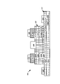
図7は、本開示のいくつかの態様による、エミッタメサがメッシュ構造として構成されたHBTの別の例示的な実装形態を示す図である。HBT700は、HBT300と同様であるが、異なるエミッタメサメッシュ構造を有する。HBT700は、コレクタメサ702と、コレクタメサ702上のベースメサ704と、ベースメサ704上のエミッタメサ706とを備える。エミッタメサ706は、メッシュ状構造として配置される。エミッタメサ706は、複数の開口710を有する。複数の開口710は、ベースメサ704上に配置されベースメサ404に接続された複数の卑金属714用の窓を構成する。複数の卑金属714は、金属の別の層(または複数の層)(図示せず)を通して接続され、互いに電気的に結合される。エミッタ金属(図示せず)は、エミッタメサ706上に位置する。エミッタ金属は、エミッタメサ706を完全に覆ってもまたは部分的に覆ってもよい。HBT700はまた、HBT700のコレクタとの接続部を構成する1つまたは複数のコレクタ金属712をコレクタメサ702上に備える。
FIG. 7 is a diagram illustrating another example implementation of an HBT with an emitter mesa configured as a mesh structure, in accordance with certain aspects of the present disclosure;
複数の開口410が方形状であるエミッタメサ406とは異なり、複数の開口710は六角形状である。この六角形は、方形よりも高いパッキング密度を実現し、同じ出力電力の下でのHBT用の面積を狭くする。六角形の開口に加えて、ベースとの接続部を最大にし、ベース抵抗を低減させるために複数の卑金属714が六角形であってもよい。
Unlike the
図5および図6におけるHBTと同様に、HBT700は、エミッタメサ706を囲む任意の卑金属(図示せず)を備えてもよい。任意の卑金属は、(図5に示すように)ドーナツ状であってもよく、または金属の1つまたは複数のストライプを含んでもよい。任意の卑金属は、金属の別の層(または複数の層)(図示せず)を通して複数の卑金属714に接続され、それによって、任意の卑金属および複数の卑金属714が電気的に結合される。
Similar to the HBTs in FIGS. 5 and 6,
図8a~図8gは、HBTを作製する例示的なプロセスフローを示す。図8aは、必要なepiスタックを有する開始ウエハを示す。ウエハは、コレクタメサスタック852と、ベースメサスタック854と、エミッタメサスタック856とを備える。コレクタメサスタック852、ベースメサスタック854、およびエミッタメサスタック856はそれぞれ、HBTのコレクタメサ、ベースメサ、およびエミッタメサ用の開始スタックであるように画定される。コレクタメサスタック852、ベースメサスタック854、およびエミッタメサスタック856の各々は複数の副層を備えてもよい。たとえば、コレクタメサスタック852は、(たとえば、真性GaAsを含む)半絶縁基板の層802Aと(たとえば、N+GaAsを含む)サブコレクタの層802Bとを含む。ベースメサスタック854は、(たとえば、InGaPを含む)第1のエッチ停止層804Aと、(たとえば、N-GaAsを含む)コレクタ層804Bと、(たとえば、P+GaAsを含む)ベース層804Cと、(たとえば、InGaPを含む)第2のエッチ停止層804Dとを含む。図8bは、HBTのエミッタ金属を配置した後のウエハの一部を示す。エミッタメサスタック856上の1つまたは複数のエミッタ金属816は、パターニングされ画定される(リソグラフィックパターニングおよびエッチングなど)。図8cは、エミッタメサスタック856をエッチングすることによってエミッタメサをパターニングした後のウエハの一部を示す。エミッタメサスタック856は、エミッタメサ806として所望のパターンを形成するようにパターニングされエッチングされる。エミッタメサ806は、図4、図5、および図7に示す形状を含む様々な形状に形成されてもよい。図8dでは、卑金属814は、ベースメサスタック854上にパターニングされ画定される。第2のエッチ停止層804Dは、卑金属814がコレクタ層804Cに接触するようにパターニングされエッチングされる。図8eは、ベースメサを形成した後の構造を示す。ベースメサスタック854は、パターニングおよびエッチング層804A~804Dを含むベースメサ804を形成するようにパターニングされエッチングされる。図8fでは、1つまたは複数のコレクタ金属812が、コレクタメサスタック852上にパターニングされ画定される。最後に、図8gに示すように、インプラント分離リング822がHBTを囲んでもよい。インプラント分離リングは、コレクタメサ802を画定し、HBTの境界を画定する。
Figures 8a-8g show an exemplary process flow for fabricating the HBT. Figure 8a shows the starting wafer with the required epi stack. The wafer comprises
図9は、本開示のいくつかの態様による、エミッタメサがメッシュ構造として配置されたHBTを製造するための例示的な方法を示す。以下の方法900および図9に記載されたプロセスフロー図は、例示的な例にすぎず、様々な態様の動作が提示された順序で実行されなければならないことを要求または暗示するものではない。
FIG. 9 illustrates an exemplary method for fabricating an HBT with emitter mesas arranged as a mesh structure, according to some aspects of the present disclosure. The
HBT製造方法900は、必要なepiスタックを有するウエハから開始する。902において、コレクタメサスタック(たとえば、コレクタメサスタック852)、ベースメサスタック(たとえば、ベースメサスタック854)、およびエミッタメサスタック(たとえば、エミッタメサスタック856)を含む必要なepiスタックを有するウエハを準備する。各メサスタックは複数の副層を備えてもよい。たとえば、NPN HBTの場合、コレクタメサスタックは、真性GaAs半絶縁基板(たとえば、半絶縁基板802A)の層とN+GaAsサブコレクタ(たとえば、サブコレクタ802B)の層とを含んでもよい。ベースメサスタックは、第1のInGaPエッチ停止層(たとえば、エッチ停止層804A)と、N-GaAsコレクタ層(たとえば、コレクタ層804B)と、P+GaAsベース層(たとえば、ベース層804C)と、第2のInGaPエッチ停止層(たとえば、エッチ停止層804D)とを含んでもよい。
904において、エミッタメサスタック上に1つまたは複数のエミッタ金属(たとえば、エミッタ金属516または816)を配置する。
At 904, one or more emitter metals (eg,
906において、エッチングなどの適切なプロセスによってエミッタメサをパターニングし形成する。エミッタメサは、複数の開口(たとえば、複数の開口410、510、または710)を備える。複数の開口410は、(図4に示されているような)方形、矩形、(図7に示されているような)六角形などの任意の形状であってもよい。複数の開口の各開口についてのサイズおよび/または形状は異なってもよく、または同じであってもよい。複数の開口の各開口は、卑金属(たとえば、卑金属414、514、または714)を受け入れるのに十分な大きさを有し、卑金属自体のサイズと卑金属とエミッタメサとの間の必要な間隔とを含む。したがって、複数の開口の最小サイズは、使用されるプロセス技術によって制限される。同様に、1つの開口と隣接する開口との間の間隔も、設計上の選択であり、最小値は、使用されるプロセス技術によって制限される。
At 906, an emitter mesa is patterned and formed by a suitable process such as etching. The emitter mesa comprises multiple openings (eg,
908において、複数の開口に複数の卑金属(たとえば、複数の卑金属414、514、または714)を設ける。複数の卑金属は、ベースメサスタック上に位置し、HBTのベースとの接続部を構成する。複数の卑金属は、複数の開口と同じ形状を有してもよい。複数の卑金属は、金属の別の層(または複数の層)を通して接続され、互いに電気的に結合される。
At 908, a plurality of base metals (eg, a plurality of
910において、ベースメサスタック上に任意の卑金属(外側卑金属)(たとえば、卑金属524)を配置し、複数の開口内の卑金属に接続してもよい。任意の卑金属は、エミッタメサを囲み、ベース抵抗が低い場合がある。任意の卑金属は、金属の別の層(または複数の層)を通して複数の卑金属に電気的に結合される。 At 910, any base metal (outer base metal) (eg, base metal 524) may be placed on the base mesa stack and connected to the base metal in the plurality of openings. Any base metal surrounds the emitter mesa and may have a low base resistance. Any base metal is electrically coupled to multiple base metals through another layer (or layers) of metal.
912において、エッチングなどのプロセスによってベースメサ(たとえば、ベースメサ404、504、704、または804)をパターニングし形成する。
At 912, a base mesa (eg,
914において、コレクタメサスタック上に1つまたは複数のコレクタ金属(たとえば、コレクタ金属412、512、712、または812)を配置する。
At 914, one or more collector metals (eg,
さらに、コレクタメサスタック内に分離リングを配置することによって、コレクタメサをさらに画定してもよい。分離リングは、HBTの境界も形成する。 Additionally, the collector mesa may be further defined by placing an isolation ring within the collector mesa stack. The isolation ring also forms the boundary of the HBT.
本開示のこれまで説明は、任意の当業者が本開示を実施できるようにするか、または使用できるようにするために提供される。本開示の様々な変更が当業者に容易に明らかになり、本明細書で定義される一般原理は、本開示の趣旨または範囲から逸脱することなく他の変形形態に適用されてもよい。したがって、本開示は本明細書で説明する例に限定されるものではなく、本明細書で開示する原理および新規の特徴と一致する最も広い範囲を与えられるべきである。 The previous description of the disclosure is provided to enable any person skilled in the art to make or use the disclosure. Various modifications of this disclosure will be readily apparent to those skilled in the art, and the general principles defined herein may be applied to other variations without departing from the spirit or scope of this disclosure. Accordingly, the present disclosure is not to be limited to the examples described herein, but is to be accorded the broadest scope consistent with the principles and novel features disclosed herein.
100 HBT
102 コレクタメサ
104 ベースメサ
106 ストライプ、エミッタメサ
112 コレクタ金属
114 卑金属
116 エミッタ金属
200 断面
300 NPN HBT
302 コレクタメサ
302A 半絶縁GaAs基板
302B N+GaAsサブコレクタ
304 ベースメサ
304A 第1のInGaPエッチ停止層
304B N-GaAsコレクタ
304C P+GaAsベース
304D 第2のInGaPエッチ停止層
306 エミッタメサ
312 コレクタ金属
314 卑金属
316 エミッタ金属
400 HBT
402 コレクタメサ
404 ベースメサ
406 エミッタメサ
410 開口
412 コレクタ金属
414 卑金属
500 HBT
502 コレクタメサ
504 ベースメサ
506 エミッタメサ
510 開口
512 コレクタ金属
514 卑金属
516 エミッタ金属
524 任意の卑金属
600 断面
700 HBT
702 コレクタメサ
704 ベースメサ
706 エミッタメサ
710 開口
712 コレクタ金属
714 卑金属
802 コレクタメサ
802A 半絶縁基板の層
802B サブコレクタの層
804 ベースメサ
804A 第1のエッチ停止層
804B コレクタ層
804C ベース層
804D 第2のエッチ停止層
806 エミッタメサ
812 コレクタ金属
814 卑金属
816 エミッタ金属
822 インプラント分離リング
852 コレクタメサスタック
854 ベースメサスタック
856 エミッタメサスタック
900 方法
100 HBTs
102
302
402
502
702
Claims (15)
コレクタメサと、
前記コレクタメサ上のベースメサと、
前記ベースメサ上のエミッタメサであって、複数の開口を有するエミッタメサと、
前記ベースメサに接続された前記複数の開口内の複数の卑金属と、
前記エミッタメサの外部に配置され、前記ベースメサに接続された外側卑金属とを備え、
前記複数の開口が前記複数の卑金属用の窓を構成し、
前記エミッタメサの外部に配置され、前記ベースメサに接続された外側卑金属をさらに備え、前記複数の卑金属と前記外側卑金属は電気的に結合され、
前記外側卑金属は、前記エミッタメサを囲むように配置され、
前記外側卑金属は、金属の別の層を通して前記複数の卑金属に接続されている、ヘテロ接合バイポーラトランジスタ(HBT)。 A heterojunction bipolar transistor (HBT),
a collector mesa;
a base mesa above the collector mesa;
an emitter mesa on the base mesa, the emitter mesa having a plurality of openings;
a plurality of base metals in the plurality of openings connected to the base mesa ;
an outer base metal positioned external to the emitter mesa and connected to the base mesa ;
said plurality of openings forming windows for said plurality of base metals;
further comprising an outer base metal positioned external to the emitter mesa and connected to the base mesa, wherein the plurality of base metals and the outer base metal are electrically coupled;
the outer base metal is arranged to surround the emitter mesa;
A heterojunction bipolar transistor (HBT) wherein said outer base metal is connected to said plurality of base metals through another layer of metal .
コレクタメサスタックと、ベースメサスタックと、エミッタメサスタックとを備えるウエハを準備するステップと、
前記エミッタメサスタックをパターニングして複数の開口を有するエミッタメサを形成するステップと、
前記ベースメサスタックに接続された前記複数の開口内に複数の卑金属を設けるステップと、
前記ベースメサスタックをパターニングしてベースメサを形成するステップと、
前記エミッタメサの外部に配置され、前記ベースメサに接続された外側卑金属を設けるステップとを含み、
前記複数の開口が前記複数の卑金属用の窓を構成し、
前記複数の卑金属と前記外側卑金属が電気的に結合され、
前記外側卑金属は、前記エミッタメサを囲むように配置され、
前記外側卑金属は、金属の別の層を通して前記複数の卑金属に接続される、方法。 A method for manufacturing a heterojunction bipolar transistor (HBT) comprising:
providing a wafer comprising a collector mesa stack, a base mesa stack and an emitter mesa stack;
patterning the emitter mesa stack to form an emitter mesa having a plurality of openings;
providing a plurality of base metals within the plurality of openings connected to the base mesa stack;
patterning the base mesa stack to form a base mesa ;
providing an outer base metal positioned external to the emitter mesa and connected to the base mesa;
said plurality of openings forming windows for said plurality of base metals;
electrically coupling the plurality of base metals and the outer base metal;
the outer base metal is arranged to surround the emitter mesa;
The method , wherein the outer base metal is connected to the plurality of base metals through another layer of metal .
前記複数の開口が2×2アレイ、3×3アレイまたは3×1アレイとして配置されるか、または、前記エミッタメサが4つ以上の開口を有する、請求項13に記載の方法。 each of the plurality of openings having the same size;
14. The method of claim 13 , wherein the plurality of openings are arranged as a 2x2 array, a 3x3 array or a 3x1 array, or the emitter mesa has four or more openings .
Applications Claiming Priority (3)
| Application Number | Priority Date | Filing Date | Title |
|---|---|---|---|
| US15/834,100 | 2017-12-07 | ||
| US15/834,100 US20190181251A1 (en) | 2017-12-07 | 2017-12-07 | Mesh structure for heterojunction bipolar transistors for rf applications |
| PCT/US2018/059532 WO2019112741A1 (en) | 2017-12-07 | 2018-11-07 | Emitter-base mesh structure in heterojunction bipolar transistors for rf applications |
Publications (3)
| Publication Number | Publication Date |
|---|---|
| JP2021506114A JP2021506114A (en) | 2021-02-18 |
| JP2021506114A5 JP2021506114A5 (en) | 2021-11-25 |
| JP7201684B2 true JP7201684B2 (en) | 2023-01-10 |
Family
ID=64477288
Family Applications (1)
| Application Number | Title | Priority Date | Filing Date |
|---|---|---|---|
| JP2020530490A Active JP7201684B2 (en) | 2017-12-07 | 2018-11-07 | Mesh structures for heterojunction bipolar transistors for RF applications |
Country Status (9)
| Country | Link |
|---|---|
| US (1) | US20190181251A1 (en) |
| EP (1) | EP3721477A1 (en) |
| JP (1) | JP7201684B2 (en) |
| KR (1) | KR102645071B1 (en) |
| CN (1) | CN111448665B (en) |
| BR (1) | BR112020011108B1 (en) |
| SG (1) | SG11202003686WA (en) |
| TW (1) | TWI813598B (en) |
| WO (1) | WO2019112741A1 (en) |
Families Citing this family (5)
| Publication number | Priority date | Publication date | Assignee | Title |
|---|---|---|---|---|
| WO2020257974A1 (en) * | 2019-06-24 | 2020-12-30 | 华为技术有限公司 | Heterojunction bipolar transistor and preparation method therefor |
| JP2021048250A (en) * | 2019-09-18 | 2021-03-25 | 株式会社村田製作所 | Semiconductor device |
| JP2021132100A (en) * | 2020-02-19 | 2021-09-09 | 株式会社村田製作所 | High-frequency power amplifier element |
| CN113594239B (en) * | 2021-07-20 | 2022-09-27 | 弘大芯源(深圳)半导体有限公司 | Bipolar power transistor with grid structure |
| CN113921598B (en) * | 2021-08-25 | 2023-06-20 | 厦门市三安集成电路有限公司 | Metal wiring method of HBT device |
Citations (5)
| Publication number | Priority date | Publication date | Assignee | Title |
|---|---|---|---|---|
| JP2001230261A (en) | 2000-02-16 | 2001-08-24 | Nec Corp | Semconductor device and its manufacturing method |
| JP2003522414A (en) | 2000-01-31 | 2003-07-22 | インフィネオン テクノロジーズ アクチェンゲゼルシャフト | Bipolar transistor |
| JP2006049693A (en) | 2004-08-06 | 2006-02-16 | Matsushita Electric Ind Co Ltd | Semiconductor device |
| JP2007520086A (en) | 2004-01-30 | 2007-07-19 | トライクェント セミコンダクター,インク. | Bipolar junction transistor geometry |
| JP2010080925A (en) | 2008-08-26 | 2010-04-08 | Sanyo Electric Co Ltd | Semiconductor device |
Family Cites Families (24)
| Publication number | Priority date | Publication date | Assignee | Title |
|---|---|---|---|---|
| US3319139A (en) * | 1964-08-18 | 1967-05-09 | Hughes Aircraft Co | Planar transistor device having a reentrant shaped emitter region with base connection in the reentrant portion |
| NL6813997A (en) * | 1968-09-30 | 1970-04-01 | ||
| JPS5818964A (en) * | 1981-07-28 | 1983-02-03 | Fujitsu Ltd | Semiconductor device |
| JPS59210668A (en) * | 1983-05-16 | 1984-11-29 | Fujitsu Ltd | Semiconductor device |
| JPS60165759A (en) * | 1984-02-07 | 1985-08-28 | Nippon Denso Co Ltd | Integrated circuit element |
| US4654687A (en) * | 1985-03-28 | 1987-03-31 | Francois Hebert | High frequency bipolar transistor structures |
| US5140399A (en) * | 1987-04-30 | 1992-08-18 | Sony Corporation | Heterojunction bipolar transistor and the manufacturing method thereof |
| JPH01189961A (en) * | 1988-01-26 | 1989-07-31 | Mitsubishi Electric Corp | Semiconductor device |
| US5502338A (en) * | 1992-04-30 | 1996-03-26 | Hitachi, Ltd. | Power transistor device having collector voltage clamped to stable level over wide temperature range |
| JPH08279562A (en) * | 1994-07-20 | 1996-10-22 | Mitsubishi Electric Corp | Semiconductor device and manufacture thereof |
| JP2002076014A (en) * | 2000-08-30 | 2002-03-15 | Mitsubishi Electric Corp | High frequency semiconductor device |
| JP3847756B2 (en) * | 2004-02-25 | 2006-11-22 | 松下電器産業株式会社 | High frequency amplifier circuit |
| JP4089662B2 (en) * | 2004-07-21 | 2008-05-28 | ソニー株式会社 | Bipolar transistor and manufacturing method thereof |
| JP2006332117A (en) * | 2005-05-23 | 2006-12-07 | Sharp Corp | Transistor structure and electronic apparatus |
| US7566920B2 (en) * | 2005-07-13 | 2009-07-28 | Panasonic Corporation | Bipolar transistor and power amplifier |
| US8415764B2 (en) * | 2009-06-02 | 2013-04-09 | Taiwan Semiconductor Manufacturing Company, Ltd. | High-voltage BJT formed using CMOS HV processes |
| EP2458639A1 (en) * | 2010-11-25 | 2012-05-30 | Nxp B.V. | Bipolar transistor with base trench contacts insulated from the emitter. |
| TWI512905B (en) * | 2012-06-13 | 2015-12-11 | Win Semiconductors Corp | Integrated structure of compound semiconductor devices |
| TWI540722B (en) * | 2013-04-17 | 2016-07-01 | Win Semiconductors Corp | Layout structure of heterojunction bipolar transistors |
| US8994075B1 (en) * | 2013-10-11 | 2015-03-31 | Rf Micro Devices, Inc. | Heterojunction bipolar transistor geometry for improved power amplifier performance |
| US20160020307A1 (en) * | 2014-07-16 | 2016-01-21 | Win Semiconductors Corp. | Heterojunction Bipolar Transistor |
| US20160141220A1 (en) * | 2014-11-18 | 2016-05-19 | Sumitomo Electric Industries, Ltd. | Hetero-bipolar transistor and method for producing the same |
| WO2016132594A1 (en) * | 2015-02-17 | 2016-08-25 | 株式会社村田製作所 | Heterojunction bipolar transistor |
| TWI585907B (en) * | 2016-05-13 | 2017-06-01 | 穩懋半導體股份有限公司 | An advanced moisture resistant structure of compound semiconductor integrated circuits |
-
2017
- 2017-12-07 US US15/834,100 patent/US20190181251A1/en not_active Abandoned
-
2018
- 2018-11-07 EP EP18808577.3A patent/EP3721477A1/en active Pending
- 2018-11-07 JP JP2020530490A patent/JP7201684B2/en active Active
- 2018-11-07 WO PCT/US2018/059532 patent/WO2019112741A1/en unknown
- 2018-11-07 CN CN201880078600.6A patent/CN111448665B/en active Active
- 2018-11-07 SG SG11202003686WA patent/SG11202003686WA/en unknown
- 2018-11-07 KR KR1020207015816A patent/KR102645071B1/en active IP Right Grant
- 2018-11-07 BR BR112020011108-2A patent/BR112020011108B1/en active IP Right Grant
- 2018-11-12 TW TW107140015A patent/TWI813598B/en active
Patent Citations (5)
| Publication number | Priority date | Publication date | Assignee | Title |
|---|---|---|---|---|
| JP2003522414A (en) | 2000-01-31 | 2003-07-22 | インフィネオン テクノロジーズ アクチェンゲゼルシャフト | Bipolar transistor |
| JP2001230261A (en) | 2000-02-16 | 2001-08-24 | Nec Corp | Semconductor device and its manufacturing method |
| JP2007520086A (en) | 2004-01-30 | 2007-07-19 | トライクェント セミコンダクター,インク. | Bipolar junction transistor geometry |
| JP2006049693A (en) | 2004-08-06 | 2006-02-16 | Matsushita Electric Ind Co Ltd | Semiconductor device |
| JP2010080925A (en) | 2008-08-26 | 2010-04-08 | Sanyo Electric Co Ltd | Semiconductor device |
Also Published As
| Publication number | Publication date |
|---|---|
| BR112020011108B1 (en) | 2024-01-23 |
| KR20200090174A (en) | 2020-07-28 |
| KR102645071B1 (en) | 2024-03-06 |
| CN111448665A (en) | 2020-07-24 |
| EP3721477A1 (en) | 2020-10-14 |
| JP2021506114A (en) | 2021-02-18 |
| TWI813598B (en) | 2023-09-01 |
| BR112020011108A2 (en) | 2020-11-17 |
| CN111448665B (en) | 2024-04-16 |
| WO2019112741A1 (en) | 2019-06-13 |
| US20190181251A1 (en) | 2019-06-13 |
| TW201937729A (en) | 2019-09-16 |
| SG11202003686WA (en) | 2020-06-29 |
Similar Documents
| Publication | Publication Date | Title |
|---|---|---|
| JP7201684B2 (en) | Mesh structures for heterojunction bipolar transistors for RF applications | |
| US8697532B2 (en) | InP based heterojunction bipolar transistors with emitter-up and emitter-down profiles on a common wafer | |
| JP4970054B2 (en) | Bipolar junction transistor geometry | |
| JP4056226B2 (en) | Semiconductor device | |
| US20060157825A1 (en) | Semiconductor device and manufacturing the same | |
| JP2006332295A (en) | Hetero-junction bipolar transistor and manufacturing method thereof | |
| US20060108665A1 (en) | Semiconductor device, manufacturing method of the same, and electronic device | |
| US7495312B2 (en) | Method for producing vertical bipolar transistors and integrated circuit | |
| JP2007027269A (en) | Bipolar transistor and power amplifier | |
| JP5073407B2 (en) | Multiple transistor semiconductor structure | |
| WO2005022580A1 (en) | Heterojunction bipolar transistor with tunnelling mis emitter junction | |
| JP3369202B2 (en) | Power transistor | |
| CN113903799A (en) | Vertical high blocking group III-V bipolar transistor | |
| US20130256756A1 (en) | Integrated circuit having a staggered heterojunction bipolar transistor array | |
| CN113066723B (en) | Heterojunction bipolar transistor and manufacturing method thereof | |
| JP2004274430A (en) | Power amplifier module and method of manufacturing the same | |
| JP2007036138A (en) | Bipolar transistor and power amplifier | |
| JP2005011951A (en) | Bipolar transistor and bipolar transistor arrangement structure | |
| JP2010034312A (en) | Semiconductor device and manufacturing method therefor | |
| JP2021016076A (en) | Semiconductor device | |
| JP2005101402A (en) | Semiconductor device and method for manufacturing same | |
| JP2001326283A (en) | Method for manufacturing semiconductor device and semiconductor | |
| JPS637470B2 (en) | ||
| JP2005101134A (en) | Semiconductor device and its manufacturing method | |
| JP2004235385A (en) | Bipolar transistor and semiconductor device using the same |
Legal Events
| Date | Code | Title | Description |
|---|---|---|---|
| A521 | Request for written amendment filed |
Free format text: JAPANESE INTERMEDIATE CODE: A523 Effective date: 20211015 |
|
| A621 | Written request for application examination |
Free format text: JAPANESE INTERMEDIATE CODE: A621 Effective date: 20211015 |
|
| A977 | Report on retrieval |
Free format text: JAPANESE INTERMEDIATE CODE: A971007 Effective date: 20221114 |
|
| TRDD | Decision of grant or rejection written | ||
| A01 | Written decision to grant a patent or to grant a registration (utility model) |
Free format text: JAPANESE INTERMEDIATE CODE: A01 Effective date: 20221128 |
|
| A61 | First payment of annual fees (during grant procedure) |
Free format text: JAPANESE INTERMEDIATE CODE: A61 Effective date: 20221222 |
|
| R150 | Certificate of patent or registration of utility model |
Ref document number: 7201684 Country of ref document: JP Free format text: JAPANESE INTERMEDIATE CODE: R150 |