JP7094635B2 - Cleaning device - Google Patents
Cleaning device Download PDFInfo
- Publication number
- JP7094635B2 JP7094635B2 JP2018222458A JP2018222458A JP7094635B2 JP 7094635 B2 JP7094635 B2 JP 7094635B2 JP 2018222458 A JP2018222458 A JP 2018222458A JP 2018222458 A JP2018222458 A JP 2018222458A JP 7094635 B2 JP7094635 B2 JP 7094635B2
- Authority
- JP
- Japan
- Prior art keywords
- cleaning
- cleaning member
- applicator
- contact
- substrate
- Prior art date
- Legal status (The legal status is an assumption and is not a legal conclusion. Google has not performed a legal analysis and makes no representation as to the accuracy of the status listed.)
- Active
Links
Images


Classifications
-
- B—PERFORMING OPERATIONS; TRANSPORTING
- B05—SPRAYING OR ATOMISING IN GENERAL; APPLYING FLUENT MATERIALS TO SURFACES, IN GENERAL
- B05C—APPARATUS FOR APPLYING FLUENT MATERIALS TO SURFACES, IN GENERAL
- B05C11/00—Component parts, details or accessories not specifically provided for in groups B05C1/00 - B05C9/00
- B05C11/10—Storage, supply or control of liquid or other fluent material; Recovery of excess liquid or other fluent material
-
- B—PERFORMING OPERATIONS; TRANSPORTING
- B05—SPRAYING OR ATOMISING IN GENERAL; APPLYING FLUENT MATERIALS TO SURFACES, IN GENERAL
- B05C—APPARATUS FOR APPLYING FLUENT MATERIALS TO SURFACES, IN GENERAL
- B05C5/00—Apparatus in which liquid or other fluent material is projected, poured or allowed to flow on to the surface of the work
- B05C5/02—Apparatus in which liquid or other fluent material is projected, poured or allowed to flow on to the surface of the work the liquid or other fluent material being discharged through an outlet orifice by pressure, e.g. from an outlet device in contact or almost in contact, with the work
Landscapes
- Coating Apparatus (AREA)
- Details Or Accessories Of Spraying Plant Or Apparatus (AREA)
Description
本発明は、スリットノズルから塗布液を吐出して基板上に塗布膜を形成する塗布器において、スリットノズル付近の先端部分を清掃する清掃装置に関するものである。 The present invention relates to a cleaning device that cleans a tip portion in the vicinity of a slit nozzle in a coating device that discharges a coating liquid from a slit nozzle to form a coating film on a substrate.
液晶ディスプレイやプラズマディスプレイ等のフラットパネルディスプレイには、ガラス等の基板上にレジスト液等の塗布液が塗布されたもの(塗布基板という)が使用されている。この塗布基板は、塗布液を均一に塗布する塗布装置によって形成されている。塗布装置は、基板を載置するステージと、載置された基板に塗布液を吐出する塗布ユニットとを有しており、塗布ユニットの塗布器から塗布液を吐出させながら、基板と塗布器とを相対的に移動させることにより、基板上に塗布膜が形成されるようになっている。 For a flat panel display such as a liquid crystal display or a plasma display, a substrate such as glass coated with a coating liquid such as a resist liquid (referred to as a coating substrate) is used. This coating substrate is formed by a coating device that uniformly coats the coating liquid. The coating device has a stage on which the substrate is placed and a coating unit that discharges the coating liquid onto the mounted substrate, and the substrate and the coating device are discharged while the coating liquid is discharged from the coating device of the coating unit. By relatively moving the coating film, a coating film is formed on the substrate.
この塗布器には、基板と対向する基板対向面に一方向に延びるスリットノズルが形成されており、スリットノズルの長手方向に亘って均一に塗布液を吐出できるようになっている。しかし、スリットノズルに塗布液が乾燥した乾燥残留液や異物(合わせて付着物と呼ぶ)が付着した状態では、その付着物等により塗布液の吐出状態が不均一化され、塗布膜に筋ムラなどの乾燥ムラが形成される原因になる。そのため、塗布器は、塗布膜の均一性を保つため、清掃装置により定期的に清掃され初期化される(例えば特許文献1参照)。 The coating device is formed with a slit nozzle extending in one direction on the surface facing the substrate facing the substrate, so that the coating liquid can be uniformly discharged over the longitudinal direction of the slit nozzle. However, when the coating liquid is dried and foreign matter (collectively referred to as deposits) adheres to the slit nozzle, the discharge state of the coating liquid becomes non-uniform due to the deposits and the like, and the coating film has streaks uneven. It causes the formation of uneven drying. Therefore, the applicator is periodically cleaned and initialized by a cleaning device in order to maintain the uniformity of the coating film (see, for example, Patent Document 1).
清掃装置100は、図7に示すように、清掃ユニット101と、この清掃ユニット101を移動させる移動装置(不図示)とを有しており、清掃ユニット101を塗布器102の長手方向に移動させることにより、塗布器102に付着した付着物P(図8(b)参照)を除去するように構成されている。具体的には、清掃ユニット101には、塗布器102のスリットノズル102a周辺部に当接する清掃部材103が設けられており、この清掃部材103を塗布器102に当接させた状態で清掃ユニット101を移動させることにより、塗布器102に付着した付着物Pを拭き取ることができる。すなわち、図7、図8(a)に示すように、スリットノズル102aを形成する基板対向面104、及び、傾斜側面105に清掃部材103を当接させた状態で移動させることにより、基板対向面104、傾斜側面105に付着した付着物Pが除去できるようになっている。
As shown in FIG. 7, the
近年ではフレキシブルディスプレイが開発されており、フレキシブルディスプレイ用途の塗布基板の形成には、粘度の高い塗布液が用いられる。そのため、一度塗布器102に付着した塗布液が固化してしまうと、上記清掃装置100では塗布器102に付着した付着物Pを除去できないという問題があった。すなわち、上記清掃装置100に用いられる清掃部材103は、主にゴム等が用いられており、清掃時には、ゴム製の清掃部材103を塗布器102に押し当てることにより密着させて移動させる。塗布液の粘度が低い場合には、清掃部材103が当接する相手面に沿って変形することにより、付着物Pを剥がして除去することが可能であるが、高粘度の塗布液の場合には、その付着物Pが硬質になるため、従来の清掃部材103の押し当てる力では除去することができない。すなわち、図8(b)に示すように、清掃部材103が付着物Pに当接すると、その付着物Pを避けるように当初に設定した清掃部材103と塗布器102との接触姿勢が弾性的に変化するため、清掃部材103と塗布器102との間に隙間ができてしまい、その隙間により筋状の拭き残しが形成される問題があった。清掃部材103の押し当てる力を増大させると、ゴム製の清掃部材103の剛性が低く、基板対向面104、及び、傾斜側面105に当接した清掃部材103が反るように変形してしまうことにより、基板対向面104、及び、傾斜側面105と清掃部材103との間に隙間が生じ、基板対向面104、及び、傾斜側面105全体に拭き残しができてしまうという問題があった。
In recent years, flexible displays have been developed, and a highly viscous coating liquid is used to form a coating substrate for flexible display applications. Therefore, once the coating liquid adhering to the
本発明は、上記の問題点に鑑みてなされたものであり、高粘度の塗布液を用いる塗布器であっても、塗布器に付着した付着物等を除去することができる清掃装置を提供することを目的としている。 The present invention has been made in view of the above problems, and provides a cleaning device capable of removing deposits and the like adhering to the coater even with a coater using a highly viscous coating solution. The purpose is.
上記課題を解決するために本発明の清掃装置は、基板と対向する基板対向面に形成された一方向に延びるスリットノズルから塗布液を吐出して基板上に塗布膜を形成する塗布器に付着した付着物を清掃する清掃装置であって、前記スリットノズルに対向した状態で前記塗布器に当接する清掃ユニットと、前記清掃ユニットが前記塗布器に当接した状態で前記塗布器の長手方向に相対的に移動させる移動装置と、を備えており、前記清掃ユニットは、清掃移動方向前側に配置される第1清掃部とこの第1清掃部よりも後側に配置される第2清掃部とを備え、第1清掃部は、前記塗布器における前記基板対向面とこの基板対向面に連続する傾斜側面とに当接する第1清掃部材を有し、第2清掃部は、前記塗布器における前記基板対向面と前記傾斜側面とに当接する第2清掃部材を有しており、前記第1清掃部材は、前記第2清掃部材に比べて当接する相手面に沿って変形しにくい剛性の高い材料で形成されており、第2清掃部材は、当接する相手面に沿って弾性変形する材料で形成されており、前記第1清掃部材は、前記基板対向面に当接する対向当接部と、前記傾斜側面に当接する側面当接部とが別体に形成されており、前記対向当接部と前記側面当接部とが独立して固定され、前記対向当接部が前記基板対向面に沿って当接し、前記側面当接部が前記傾斜側面に沿って当接するように、それぞれ当接状態を調節可能に固定されていることを特徴としている。 In order to solve the above problems, the cleaning device of the present invention adheres to a coating device that forms a coating film on a substrate by ejecting a coating liquid from a slit nozzle extending in one direction formed on a substrate facing surface facing the substrate. It is a cleaning device that cleans the adhered deposits, and is a cleaning unit that abuts on the applicator while facing the slit nozzle, and a cleaning unit that abuts on the applicator in the longitudinal direction of the applicator. The cleaning unit includes a moving device that moves relatively, and the cleaning unit includes a first cleaning unit arranged on the front side in the cleaning moving direction and a second cleaning unit arranged on the rear side of the first cleaning unit. The first cleaning unit has a first cleaning member that comes into contact with the substrate facing surface of the applicator and the inclined side surface continuous with the substrate facing surface, and the second cleaning unit is the coating device. It has a second cleaning member that abuts on the substrate facing surface and the inclined side surface, and the first cleaning member is a highly rigid material that is less likely to be deformed along the mating surface that abuts as compared with the second cleaning member. The second cleaning member is made of a material that elastically deforms along the mating surface to be abutted with, and the first cleaning member is formed by a facing abutting portion that abuts on the substrate facing surface and the above-mentioned. The side contact portion that abuts on the inclined side surface is formed separately, the facing contact portion and the side contact portion are independently fixed, and the facing contact portion is along the substrate facing surface. The contact state is adjustable and fixed so that the side contact portion abuts along the inclined side surface.
上記清掃装置によれば、第1清掃部材が第2清掃部材よりも剛性が高く形成されているため、塗布器に付着した付着物を最初に第1清掃部の清掃部材で掻き落とし、その後、第2清掃部材で拭き取りを行うことにより、付着物を除去することができる。すなわち、第1清掃部材は、第2清掃部材よりも当接部分に沿って弾性変形しにくい材料で形成されているため、清掃動作時に仮に粘性の高い塗布液が付着した付着物と接触した場合でも、その付着物を回避するような弾性変形が行われず、当初に設定した清掃部材が塗布器に接触する姿勢が付着物との接触により変化するのを極力抑えることができる。そのため、清掃ユニットを移動させる力が付着物を掻き取る力として十分に作用させることができ、硬質な付着物等であっても掻き取ることができる。そして、次の第2清掃部材は、当接する相手面に沿って弾性変形して拭き取り動作を行うため、第1清掃部材で掻き落とした後に残留する付着物を確実に拭き取ることができ、基板対向面、及び、傾斜側面に付着した付着物をきれいに除去することができる。
また、第1清掃部材の対向当接部と側面当接部とが別体に形成されており、それぞれが基板対向面、傾斜側面に対して当接状態を調節できるため、対向当接部と側面当接部とが一体的に形成されている場合に比べて、対向当接部と基板対向面、側面当接部と傾斜側面それぞれの隙間を調節することができる。これにより、例えば対向当接部の取付状態により、側面当接部と傾斜側面との間に隙間が形成されて拭き残しが形成されるのを抑えることができる。
According to the cleaning device, since the first cleaning member is formed to have higher rigidity than the second cleaning member, the deposits adhering to the applicator are first scraped off by the cleaning member of the first cleaning unit, and then. By wiping with the second cleaning member, the deposits can be removed. That is, since the first cleaning member is made of a material that is less likely to be elastically deformed along the contact portion than the second cleaning member, if it comes into contact with a deposit to which a highly viscous coating liquid is attached during the cleaning operation. However, elastic deformation that avoids the deposits is not performed, and it is possible to suppress the posture of the initially set cleaning member in contact with the applicator from changing due to contact with the deposits as much as possible. Therefore, the force for moving the cleaning unit can sufficiently act as a force for scraping off the deposits, and even hard deposits and the like can be scraped off. Then, since the next second cleaning member is elastically deformed along the contact surface to perform the wiping operation, the deposits remaining after being scraped off by the first cleaning member can be reliably wiped off, and the substrate faces each other. The deposits adhering to the surface and the inclined side surface can be removed cleanly.
Further, since the facing contact portion and the side contact portion of the first cleaning member are formed separately and the contact state can be adjusted with respect to the substrate facing surface and the inclined side surface, respectively, the facing contact portion and the side contact portion are formed. Compared with the case where the side contact portion is integrally formed, the gaps between the facing contact portion and the substrate facing surface and the side contact portion and the inclined side surface can be adjusted. Thereby, for example, depending on the mounting state of the facing contact portion, it is possible to suppress the formation of a gap between the side contact portion and the inclined side surface and the formation of unwiped residue.
また、第1清掃部材、第2清掃部材の具体的な態様としては、例えば、前記第1清掃部材は、樹脂で形成され、前記第2清掃部材は、ゴムで形成される構成とすることができる。 Further, as a specific embodiment of the first cleaning member and the second cleaning member, for example, the first cleaning member may be made of resin and the second cleaning member may be made of rubber. can.
また、前記第1清掃部は、第1清掃部材を塗布器に押し当てる第1台座部上に設けられ、前記第2清掃部は、第2清掃部材を塗布器に押し当てる第2台座部上に設けられ、前記第1台座部と前記第2台座部とは、独立して設けられている構成としてもよい。 Further, the first cleaning portion is provided on the first pedestal portion that presses the first cleaning member against the applicator, and the second cleaning portion is on the second pedestal portion that presses the second cleaning member against the applicator. The first pedestal portion and the second pedestal portion may be provided independently of the above.
この構成によれば、第1台座部と第2台座部とは、独立して設けられているため、第1清掃部材と第2清掃部材とが塗布器に押し当てる押し当て力をそれぞれ独立して享受できるため、第1清掃部材、第2清掃部材の取付けの調節が容易となり、また第1清掃部材、第2清掃部材の拭き取り性能を安定させることができる。 According to this configuration, since the first pedestal portion and the second pedestal portion are provided independently, the pressing force that the first cleaning member and the second cleaning member press against the applicator is independent of each other. Therefore, the attachment of the first cleaning member and the second cleaning member can be easily adjusted, and the wiping performance of the first cleaning member and the second cleaning member can be stabilized.
本発明によれば、高粘度の塗布液を用いる塗布器であっても、塗布器に付着した付着物等を除去することができる。 According to the present invention, even a coating device using a highly viscous coating liquid can remove deposits and the like adhering to the coating device.
以下、本発明の実施の形態を図面に基づいて説明する。 Hereinafter, embodiments of the present invention will be described with reference to the drawings.
図1は、本発明の清掃装置を備える塗布装置を概略的に示す斜視図、図2は、本発明の清掃装置を概略的に示す図、図3は、清掃装置を長手方向から見た図である。 FIG. 1 is a perspective view schematically showing a coating device including the cleaning device of the present invention, FIG. 2 is a view schematically showing the cleaning device of the present invention, and FIG. 3 is a view of the cleaning device from a longitudinal direction. Is.
図1~図3に示すように、塗布装置1は、基板10上に薬液やレジスト液等の液状物(以下、塗布液と称す)の塗布膜を形成するものであり、基板10を載置するためのステージ21と、このステージ21に対し特定方向に移動可能に構成される塗布ユニット3とを備えている。
As shown in FIGS. 1 to 3, the coating device 1 forms a coating film of a liquid substance (hereinafter referred to as a coating liquid) such as a chemical solution or a resist solution on the
なお、以下の説明では、塗布ユニット3が移動する方向をX軸方向、これと水平面上で直交する方向をY軸方向、X軸およびY軸方向の双方に直交する方向をZ軸方向として説明を進めることとする。 In the following description, the direction in which the coating unit 3 moves is defined as the X-axis direction, the direction orthogonal to this in the horizontal plane is defined as the Y-axis direction, and the direction orthogonal to both the X-axis and the Y-axis directions is defined as the Z-axis direction. Will proceed.
ステージ21は、ロボットハンド等により搬入された基板10を載置するものである。このステージ21には、基板保持手段が設けられており、この基板保持手段により基板10が保持されるようになっている。具体的には、ステージ21の表面に形成された複数の吸引孔が形成されており、この吸引孔に吸引力を発生させることにより基板10をステージ21の表面に吸着させて保持できるようになっている。
The
また、塗布ユニット3は、基板10上に塗布液を吐出して塗布膜を形成するものである。この塗布ユニット3は、図1、図2に示すように、塗布液を吐出する塗布器30と、この塗布器30を保持するガントリ部35とを有しており、X軸方向に移動可能に形成されている。すなわち、塗布ユニット3を移動させる駆動ユニットが設けられており、この駆動ユニットを制御することによりガントリ部35をX軸方向に移動させることができるようになっている。具体的には、駆動ユニットは、ステージ21のY軸方向端部に設けられるX軸方向に延びるレールと、脚部35aに取り付けられたガントリ部35を駆動させるリニアモータとを有しており、ガントリ部35がレールにスライド自在に取り付けられている。そして、このリニアモータを駆動制御することにより、塗布ユニット3がX軸方向に移動し、任意の位置で停止することができる。本実施形態では、ステージ21と、ステージ21の外側に設置される清掃装置5とに移動できるようになっている。
Further, the coating unit 3 discharges a coating liquid onto the
また、ガントリ部35には、塗布器30を昇降させる昇降機構が設けられている。具体的には、昇降機構を作動させることにより、塗布器30が基板10に対して接離できるようになっている。これにより、塗布動作中には、ステージ21上の基板10に対して適切な高さ位置に位置することができる。また、後述の清掃装置5に対しても昇降動作できるようになっており、昇降機構を作動させることにより、清掃装置5に対して接離できるようになっている。
Further, the
また、塗布器30は、塗布液を吐出して基板10上に塗布膜を形成するものである。この塗布器30は、一方向に延びる形状を有する柱状部材であり、塗布ユニット3の走行方向(X軸方向)とほぼ直交するように設けられている。この塗布器30は、基板10と対向する基板対向面31と、基板10に対して所定角度を有する傾斜側面32とを有しており、基板対向面31にスリットノズル30aが形成されている。具体的には、基板対向面31は、基板10に対向しY軸方向に延びる平坦面に形成されており、この平坦面のX軸方向端部から連続して傾斜側面32が所定角度で形成されている。すなわち、塗布器30は、傾斜側面32、基板対向面31と連続するように基板10に向かって先細りの形状に形成されている。また、基板対向面31には、僅かな隙間で形成されるスリットノズル30aがY軸方向に延びるように形成されている。そして、塗布器30に塗布液が供給されると、塗布液がスリットノズル30aを通じて長手方向(Y軸方向)に亘って一様に吐出されるようになっている。したがって、このスリットノズル30aから塗布液を吐出させた状態で塗布ユニット3をX軸方向に走行させることにより、基板10上に一定厚さの塗布膜が形成されるようになっている。
Further, the
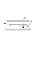
また、塗布装置1には、塗布器30の保守、初期化を行うための清掃装置5を備えている。この清掃装置5は、塗布器30に乾燥した乾燥残留液や異物(合わせて付着物と呼ぶ)を除去するものである。清掃装置5は、図5に示すように、塗布器30に付着した付着物を除去する清掃ユニット50と、清掃ユニット50を移動させる移動装置と、除去した付着物を受けるトレイ部6とを有しており、清掃ユニット50が塗布器30に当接した状態で移動させられることにより、塗布器30に付着した付着物が除去されるようになっている。
Further, the coating device 1 is provided with a cleaning device 5 for maintaining and initializing the
清掃装置5は、本実施形態では、ステージ21のX軸方向端部側に配置されており、保守、初期化動作時(清掃時という)には、トレイ部6上に塗布器30が移動し、トレイ部6上で保守、初期化処理(清掃処理という)が行われるようになっている。トレイ部6は、一方向に延びる形状を有しており、Y軸方向に沿う姿勢で配置されている。すなわち、トレイ部6は、塗布器30を覆う程度に塗布器30よりも大きく形成されており、トレイ部6上で清掃処理が行われた際に除去された付着物を受けることができる程度に形成されている。
In the present embodiment, the cleaning device 5 is arranged on the X-axis direction end side of the
また、トレイ部6内には、清掃ユニット50と、移動装置とが設けられており、移動装置を駆動制御することにより、清掃ユニット50がトレイ部6の長手方向に沿って移動できるように形成されている。移動装置は、本実施形態では、アタッチメント基台部8と、このアタッチメント基台部8を移動させるリニアモータを有しており、リニアモータが制御装置(不図示)で制御されるようになっている。すなわち、清掃時には、トレイ部6上に塗布器30が配置された状態で、制御装置がリニアモータを駆動制御すると、アタッチメント基台部8が塗布器30の長手方向一方端部から他方端部に向かって移動するように構成されている。そして、このアタッチメント基台部8上には、清掃ユニット50が設けられており、リニアモータが駆動制御されることにより、アタッチメント基台部8上の清掃ユニット50が塗布器30のスリットノズル30aに沿って移動できるようになっている。なお、本発明では、清掃ユニット50の清掃時にアタッチメント基台部8を移動させる方向を特に清掃移動方向と呼ぶ。
Further, a
清掃ユニット50は、アタッチメント基台部8上に配置されており、第1清掃部51と第2清掃部52とを有している。これら第1清掃部51と第2清掃部52は、塗布器30に当接させて付着物を除去するものであり、第1清掃部51が第2清掃部52よりも清掃移動方向前側に配置されている。そして、これら第1清掃部51が第2清掃部52が塗布器30に当接した状態で、アタッチメント基台部8を移動させることにより第1清掃部51が第2清掃部52が当接した状態で移動し、塗布器30に付着した付着物が掻き取られるとともに拭き取りが行われる。すなわち、第1清掃部51により付着物が掻き取られ、第2清掃部52により第1清掃部51で掻き取られた付着物の残留物を拭き取ることにより、塗布器30から付着物が除去されるようになっている。
The
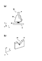
第1清掃部51は、塗布器30に当接する第1清掃部材7と、この第1清掃部材7を支持する第1台座部53とを有しており、第1清掃部材7が第1台座部53よりも上方に突出した状態で第1台座部53に固定されている。第1台座部53は、第1清掃部材7を取り付ける台座であり、アタッチメント基台部8上に取り付けられている。本実施形態では、第1台座部53は、第1清掃部材7を取り付ける清掃取付部54を有するブロック体に形成されており、バネ81を介してアタッチメント基台部8に取り付けられている。すなわち、第1台座部53は、このバネ81により鉛直方向に付勢力を受けるように構成されている。また、第1台座部53の清掃取付部54は、傾斜した平面を有しており、この傾斜平面に第1清掃部材7を清掃部材固定部57(本実施形態ではボルト55)で固定できるようになっている。すなわち、第1清掃部材7が清掃取付部54に取り付けられた状態では、第1清掃部材7の先端部分が清掃移動方向に向く傾斜姿勢に固定され、その先端部分が第1台座部53よりも上方に突出した状態で固定されるようになっている。したがって、第1台座部53に第1清掃部材7を取り付けた状態で、上方に配置される塗布器30に第1清掃部材7を当接させると、第1清掃部材7が傾斜姿勢で塗布器30に当接し、さらに当接させた状態から上方に変位させることによりバネ81が収縮することにより、バネ81の付勢力が第1清掃部材7に作用し、第1清掃部材7を所定の押圧力で塗布器30に押し当てることができるようになっている。
The
なお、第2清掃部52の第2台座部56も同様の構成を有しており、第2台座部56に第2清掃部材9を取り付けた状態で、上方に配置される塗布器30に第2清掃部材9を当接させると、第2清掃部材9が傾斜姿勢で塗布器30に当接し、さらに当接させた状態から上方に変位させることによりバネ81が収縮することにより、バネ81の付勢力が第2清掃部材9に作用し、清掃部材を所定の押圧力で塗布器30に押し当てることができるようになっている。
The
このように、第1清掃部51、第2清掃部52で、それぞれ第1台座部53、第2台座部56をバネ81を介してアタッチメント基台部8から独立させて設けているため、第1清掃部材7、第2清掃部材9が塗布器30に塗布器30に押し当てる力を独立して得ることができるため、第1清掃部材7、第2清掃部材9の拭き取り性能を安定させることができる。
As described above, in the
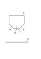
また、第1清掃部材7は、図4に示すように、塗布器30に当接して付着物を除去するものであり、平板状部材で形成されている。第1清掃部材7は、本実施形態では樹脂で形成されており、後述の第2清掃部材9に比べて変形しにくい高剛性材料で形成されている。すなわち、第1清掃部材7が塗布器30に当接した場合でも、ほとんど弾性変形することなく、元の姿勢を維持する材料で形成されている。本実施形態では、第1清掃部材7は、ポリアセタール樹脂が使用されている。
Further, as shown in FIG. 4, the
また、第1清掃部材7は、3枚の平板状部材で形成されており、塗布器30の基板対向面31に当接する対向当接部71と、傾斜側面32に当接する側面当接部72とで形成されている。具体的には、対向当接部71、側面当接部72は、それぞれ矩形状の平板部材で形成されており、第1台座部53の清掃取付部54に清掃部材固定部57で固定できるようになっている。本実施形態では、清掃部材固定部57は、ボルト55で固定するように構成されている。すなわち、対向当接部71及び側面当接部72は、ボルト55が貫通する貫通孔が形成されており、この貫通孔にボルト55を挿通させて第1台座部53のボルト孔に螺合させることにより、第1台座部53に対向当接部71及び側面当接部72を固定することができる。そして、対向当接部71及び側面当接部72が固定された状態では、図4(a)に示すように、対向当接部71の縁端部分が基板対向面31に当接し、側面当接部72の縁端部分が傾斜側面32に当接する。そして、図4(b)に示すように、対向当接部71と側面当接部72とが固定された状態では、互いに当接するように配置されており、対向当接部71の縁端部分と、側面当接部72の縁端部分とが、ほぼ連続する直線を形成するように基板対向面31及び傾斜側面32に対して接触している。すなわち、対向当接部71のみで接触すると、対向当接部71で掻き取った付着物が基板対向面31から溢れて傾斜側面32に移動して残留する場合があり、同様に、側面当接部72のみで接触すると、側面当接部72で掻き取った付着物が傾斜側面32から溢れて基板対向面31に移動して残留する場合がある。すなわち、対向当接部71、側面当接部72のみで当接させると、除去すべき付着物が残留する現象が見られるが、上述のように、対向当接部71の縁端部分、側面当接部72の縁端部分を極力連続する直線状に配置することにより、掻き取った際に溢れる付着物が移動して基板対向面31又は傾斜側面32に残留するのを抑えることができる。
Further, the
また、清掃部材固定部57は、それぞれ塗布器30との当接状態を調節できる当接調節機構を有している。本実施形態では、対向当接部71及び側面当接部72の貫通孔58が角丸長方形に形成されることで調節できるようになっている。すなわち、対向当接部71の貫通孔58は、基板対向面31に延びる角丸長方形に形成されており、側面当接部72の貫通孔58は、傾斜側面32に向かって延びる角丸長方形に形成されている。これにより、対向当接部71は基板対向面31に接離可能に取付状態を調節でき、側面当接部72は傾斜側面32に接離可能に取付状態を調節できるため、それぞれ対向当接部71及び側面当接部72は、塗布器30に対する当接状態を調節できるようになっている。これにより、対向当接部71及び側面当接部72の先端部の縁端部分全体が塗布器30に当接するように調節することにより、対向当接部71が基板対向面31に沿って当接し、側面当接部72が傾斜側面32に沿って当接するように調節できる。そして、第1清掃部材7がほとんど弾性変形することなく、元の姿勢を維持できる材料で形成されているため、清掃時に清掃移動方向に走査させた場合でも、その当接姿勢を維持することができる。したがって、清掃時において、第1清掃部材7と基板対向面31、傾斜側面32との間に隙間が形成されることを極力抑えることができ、基板対向面31、傾斜側面32に付着した付着物を塗布器30の長手方向に亘って掻き取り除去することができる。
Further, each of the cleaning
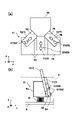
また、第2清掃部52は、図5(a)、図5(b)に示すように、塗布器30に当接する第2清掃部材9と、この第2清掃部材9を支持する第2台座部56とを有しており、清掃部材が第2台座部56よりも上方に突出した状態で第2台座部56に固定されている。この第2台座部56は、上述の通り、第1台座部53と同様の構成を有しているので、その説明を省略する。
Further, as shown in FIGS. 5A and 5B, the
第2清掃部材9は、塗布器30に当接して付着物を除去するものであり、第1清掃部材7よりも厚みのある板状部材で形成されている。第2清掃部材9は、本実施形態ではゴムで形成されており、例えば、ニトリルゴム、シリコーンゴム等、弾性変形しやすい材料が使用される。すなわち、第2清掃部材9が塗布器30に当接した場合には、当接する塗布器30の相手面に沿って弾性変形するようになっている。
The second cleaning member 9 comes into contact with the
第2清掃部材9は、1枚の板状部材であり、その先端部分にはV字状の溝が形成されている。すなわち、V字溝91が塗布器30のスリットノズル30aに当接させると、塗布器30の基板対向面31、傾斜側面32にV字溝91が沿うように形成されている。そして、第2清掃部材9は、第1台座部53と同様に、第2台座部56の清掃部材固定部57に取り付けられるようになっており、第2台座部56の清掃取付部54にボルト55で固定できるようになっている。すなわち、第2清掃部材9が第2台座部56に取り付けられた状態では、清掃移動方向に傾斜する傾斜姿勢を維持し、第2清掃部材9のV字溝91が第2台座部56よりも上方に突出した状態で固定されるようになっている。したがって、第2台座部56に第2清掃部材9を取り付けた状態で、上方に配置される塗布器30に第2部材を当接させると、第2清掃部材9のV字溝91が傾斜姿勢で塗布器30のスリットノズル30aに当接し、さらに当接させた状態から上方に変位させることによりバネ81が収縮することにより、バネ81の付勢力が第2清掃部材9に作用し、第2清掃部材9を所定の押圧力で塗布器30に押し当てることができるようになっている。そして、第2清掃部材9は、ゴムで形成されているため、V字溝91にスリットノズル30aが当接すると、V字溝91が弾性変形し、基板対向面31、傾斜側面32に密着するように変形することができる。これにより、第1清掃部材7で塗布器30に付着した付着物を掻き取った後、塗布器30に残留した付着物を仕上げるように第2清掃部材9で拭き取りすることができる。これにより、塗布液が高粘度であり、硬質の付着物が付着した場合であっても、基板対向面31、傾斜側面32に残留する付着物を除去することができる。
The second cleaning member 9 is a single plate-shaped member, and a V-shaped groove is formed at the tip portion thereof. That is, when the V-shaped
このように、上記実施形態では、第1清掃部材7が第2清掃部材9よりも剛性が高く形成されているため、塗布器30に付着した付着物を最初に第1清掃部51の清掃部材で掻き落とし、その後、第2清掃部材9で拭き取りを行うことにより、付着物を除去することができる。すなわち、第1清掃部材7は、第2清掃部材9よりも当接部分に沿って弾性変形しにくい材料で形成されているため、清掃動作時に仮に粘性の高い塗布液が付着した付着物と接触した場合でも、その付着物を回避するような弾性変形が行われず、当初に設定した第1清掃部材7が塗布器30に接触する姿勢が付着物との接触により変化するのを極力抑えることができる。そのため、清掃ユニット50を移動させる力が付着物を掻き取る力として十分に作用させることができ、硬質な付着物等であっても掻き取ることができる。そして、次の第2清掃部材9は、当接する相手面に沿って弾性変形して拭き取り動作を行うため、第1清掃部材7で掻き落とした後に残留する付着物を確実に拭き取ることができ、基板対向面31、及び、傾斜側面32に付着した付着物をきれいに除去することができる。
As described above, in the above embodiment, since the
また、上記実施形態では、第1清掃部材7が、対向当接部71、側面当接部72が別々に3枚の平板状部材で形成されている例について説明したが、図6に示すように、側面当接部72が一体型になっており、対向当接部71と側面当接部72とが2枚の平板状部材で形成されているものであってもよい。側面当接部72が一体型になっている構成であれば、2枚の平板状部材で形成されている場合に比べて、第1台座部53への取付けが1度で済むため、取付作業を容易にすることができる。
Further, in the above embodiment, an example in which the
また、上記実施形態では、第1清掃部51、第2清掃部52がそれぞれ1つずつ設ける例について説明したが、清掃移動方向前方に第1清掃部51、後方に第2清掃部52が配置されていれば、第1清掃部51及び第2清掃部52がそれぞれ複数備えるものであってもよい。すなわち、清掃移動方向前方から、第1清掃部51、第2清掃部52、第2清掃部52でもよく、第1清掃部51、第1清掃部51、第2清掃部52でもよく、第1清掃部51、第1清掃部51、第2清掃部52、第2清掃部52というものであってもよい。このように第1清掃部51、第2清掃部52が複数備えるものであれば、拭き取り性能を向上させることができる。
Further, in the above embodiment, an example in which the
また、上記実施形態では、第1清掃部51に第1清掃部材7を1つ備え、第2清掃部52に第2清掃部材9を1つ備える例について説明したが、1つの第1清掃部51(又は、第2清掃部52)に複数の第1清掃部材7(又は、第2清掃部材9)を備えるものであってもよい。
Further, in the above embodiment, an example in which the
1 塗布装置
3 塗布ユニット
5 清掃装置
7 第1清掃部材
9 第2清掃部材
30 塗布器
30a スリットノズル
31 基板対向面
32 傾斜側面
51 第1清掃部
52 第2清掃部
71 対向当接部
72 側面当接部
1 Coating device 3 Coating unit 5
Claims (3)
前記スリットノズルに対向した状態で前記塗布器に当接する清掃ユニットと、
前記清掃ユニットが前記塗布器に当接した状態で前記塗布器の長手方向に相対的に移動させる移動装置と、
を備えており、
前記清掃ユニットは、清掃移動方向前側に配置される第1清掃部とこの第1清掃部よりも後側に配置される第2清掃部とを備え、第1清掃部は、前記塗布器における前記基板対向面とこの基板対向面に連続する傾斜側面とに当接する第1清掃部材を有し、第2清掃部は、前記塗布器における前記基板対向面と前記傾斜側面とに当接する第2清掃部材を有しており、前記第1清掃部材は、前記第2清掃部材に比べて当接する相手面に沿って変形しにくい剛性の高い材料で形成されており、第2清掃部材は、当接する相手面に沿って弾性変形する材料で形成されており、
前記第1清掃部材は、前記基板対向面に当接する対向当接部と、前記傾斜側面に当接する側面当接部とが別体に形成されており、前記対向当接部と前記側面当接部とが独立して固定され、前記対向当接部が前記基板対向面に沿って当接し、前記側面当接部が前記傾斜側面に沿って当接するように、それぞれ当接状態を調節可能に固定されていることを特徴とする清掃装置。 A cleaning device that cleans the deposits adhering to the coating device that forms a coating film on the substrate by ejecting the coating liquid from a slit nozzle formed on the surface facing the substrate and extending in one direction.
A cleaning unit that comes into contact with the applicator while facing the slit nozzle, and
A moving device that moves the cleaning unit relatively in the longitudinal direction of the applicator while the cleaning unit is in contact with the applicator.
Equipped with
The cleaning unit includes a first cleaning unit arranged on the front side in the cleaning moving direction and a second cleaning unit arranged on the rear side of the first cleaning unit, and the first cleaning unit is the above-mentioned in the applicator. It has a first cleaning member that abuts on a substrate facing surface and an inclined side surface that is continuous with the substrate facing surface, and a second cleaning unit is a second cleaning that abuts on the substrate facing surface and the inclined side surface of the applicator. The first cleaning member has a member, and the first cleaning member is made of a highly rigid material that is less likely to be deformed along the mating surface with which the second cleaning member abuts, and the second cleaning member abuts. It is made of a material that elastically deforms along the mating surface and
In the first cleaning member, the facing contact portion that abuts on the substrate facing surface and the side surface contact portion that abuts on the inclined side surface are formed separately, and the facing contact portion and the side surface contact portion are formed separately. The contact state can be adjusted so that the portion is fixed independently, the facing contact portion abuts along the substrate facing surface, and the side surface abutting portion abuts along the inclined side surface. A cleaning device characterized by being fixed .
Priority Applications (3)
| Application Number | Priority Date | Filing Date | Title |
|---|---|---|---|
| JP2018222458A JP7094635B2 (en) | 2018-11-28 | 2018-11-28 | Cleaning device |
| PCT/JP2019/043645 WO2020110648A1 (en) | 2018-11-28 | 2019-11-07 | Cleaning device |
| TW108141919A TWI799664B (en) | 2018-11-28 | 2019-11-19 | cleaning device |
Applications Claiming Priority (1)
| Application Number | Priority Date | Filing Date | Title |
|---|---|---|---|
| JP2018222458A JP7094635B2 (en) | 2018-11-28 | 2018-11-28 | Cleaning device |
Publications (2)
| Publication Number | Publication Date |
|---|---|
| JP2020081994A JP2020081994A (en) | 2020-06-04 |
| JP7094635B2 true JP7094635B2 (en) | 2022-07-04 |
Family
ID=70854269
Family Applications (1)
| Application Number | Title | Priority Date | Filing Date |
|---|---|---|---|
| JP2018222458A Active JP7094635B2 (en) | 2018-11-28 | 2018-11-28 | Cleaning device |
Country Status (3)
| Country | Link |
|---|---|
| JP (1) | JP7094635B2 (en) |
| TW (1) | TWI799664B (en) |
| WO (1) | WO2020110648A1 (en) |
Citations (4)
| Publication number | Priority date | Publication date | Assignee | Title |
|---|---|---|---|---|
| JP2002177848A (en) | 2000-12-15 | 2002-06-25 | Toray Ind Inc | Apparatus and method for cleaning coating die and apparatus and method for manufacturing color filter using the same |
| JP2008149247A (en) | 2006-12-15 | 2008-07-03 | Chugai Ro Co Ltd | Discharge nozzle cleaning device |
| JP2012200614A (en) | 2011-03-23 | 2012-10-22 | Toray Eng Co Ltd | Coating apparatus and coating method |
| JP2017209633A (en) | 2016-05-26 | 2017-11-30 | 株式会社Screenホールディングス | Nozzle cleaning device, coating applicator, and nozzle cleaning method |
Family Cites Families (2)
| Publication number | Priority date | Publication date | Assignee | Title |
|---|---|---|---|---|
| JP3757992B2 (en) * | 1996-01-18 | 2006-03-22 | 東レ株式会社 | Coating apparatus and coating method, and color filter manufacturing method and manufacturing apparatus |
| JPH10216598A (en) * | 1997-02-04 | 1998-08-18 | Toray Ind Inc | Coating method and coating device, and color filter manufacturing method and manufacturing device |
-
2018
- 2018-11-28 JP JP2018222458A patent/JP7094635B2/en active Active
-
2019
- 2019-11-07 WO PCT/JP2019/043645 patent/WO2020110648A1/en not_active Ceased
- 2019-11-19 TW TW108141919A patent/TWI799664B/en active
Patent Citations (4)
| Publication number | Priority date | Publication date | Assignee | Title |
|---|---|---|---|---|
| JP2002177848A (en) | 2000-12-15 | 2002-06-25 | Toray Ind Inc | Apparatus and method for cleaning coating die and apparatus and method for manufacturing color filter using the same |
| JP2008149247A (en) | 2006-12-15 | 2008-07-03 | Chugai Ro Co Ltd | Discharge nozzle cleaning device |
| JP2012200614A (en) | 2011-03-23 | 2012-10-22 | Toray Eng Co Ltd | Coating apparatus and coating method |
| JP2017209633A (en) | 2016-05-26 | 2017-11-30 | 株式会社Screenホールディングス | Nozzle cleaning device, coating applicator, and nozzle cleaning method |
Also Published As
| Publication number | Publication date |
|---|---|
| JP2020081994A (en) | 2020-06-04 |
| WO2020110648A1 (en) | 2020-06-04 |
| TW202031365A (en) | 2020-09-01 |
| TWI799664B (en) | 2023-04-21 |
Similar Documents
| Publication | Publication Date | Title |
|---|---|---|
| KR20120108933A (en) | Coating device and coating method | |
| CN107433240B (en) | Nozzle cleaning device, coating device and nozzle cleaning method | |
| CN101623683B (en) | Device and method for coating with paste | |
| CN101204687B (en) | Coating head cleaning device for coating | |
| CN100418641C (en) | Substrate processing apparatus and substrate processing method | |
| CN106664802A (en) | Coating device, coating head and coating method | |
| JP2008149247A (en) | Discharge nozzle cleaning device | |
| CN106914366B (en) | Coater cleaning device and coater | |
| CN108855778B (en) | Coating device, coating method, and nozzle | |
| CN108855719B (en) | Nozzle cleaning device, coating device and nozzle cleaning method | |
| JP2002177848A (en) | Apparatus and method for cleaning coating die and apparatus and method for manufacturing color filter using the same | |
| JP7094635B2 (en) | Cleaning device | |
| JP4986490B2 (en) | Pre-discharge device | |
| CN108296086B (en) | Nozzle cleaning member, nozzle cleaning device, and coating device | |
| CN112547415B (en) | Coating device and coating method | |
| JP7197525B2 (en) | NOZZLE CLEANING DEVICE, COATING DEVICE, NOZZLE CLEANING METHOD, AND SCRAPER | |
| CN108855720B (en) | Nozzle cleaning device, coating device and nozzle cleaning method | |
| JP7428551B2 (en) | Cleaning parts and cleaning equipment | |
| KR102096956B1 (en) | Apparatus and Method for treating substrate | |
| JP2011056374A (en) | Coating apparatus | |
| JP5160953B2 (en) | Pre-coating device, coating device and cleaning method for pre-coating device | |
| JPH11300261A (en) | Coating die cleaning apparatus, coating method using the same, and color filter manufacturing apparatus and manufacturing method | |
| KR101041454B1 (en) | Chemical liquid cleaning device and chemical liquid applying device having same | |
| JP2008296113A (en) | Coating device | |
| KR100585064B1 (en) | Screw cleaning device for semiconductor device manufacturing |
Legal Events
| Date | Code | Title | Description |
|---|---|---|---|
| A621 | Written request for application examination |
Free format text: JAPANESE INTERMEDIATE CODE: A621 Effective date: 20210630 |
|
| A131 | Notification of reasons for refusal |
Free format text: JAPANESE INTERMEDIATE CODE: A131 Effective date: 20220511 |
|
| A521 | Request for written amendment filed |
Free format text: JAPANESE INTERMEDIATE CODE: A523 Effective date: 20220531 |
|
| TRDD | Decision of grant or rejection written | ||
| A01 | Written decision to grant a patent or to grant a registration (utility model) |
Free format text: JAPANESE INTERMEDIATE CODE: A01 Effective date: 20220621 |
|
| A61 | First payment of annual fees (during grant procedure) |
Free format text: JAPANESE INTERMEDIATE CODE: A61 Effective date: 20220621 |
|
| R150 | Certificate of patent or registration of utility model |
Ref document number: 7094635 Country of ref document: JP Free format text: JAPANESE INTERMEDIATE CODE: R150 |
|
| R250 | Receipt of annual fees |
Free format text: JAPANESE INTERMEDIATE CODE: R250 |