JP7088552B2 - Proximity exposure equipment and proximity exposure method - Google Patents
Proximity exposure equipment and proximity exposure method Download PDFInfo
- Publication number
- JP7088552B2 JP7088552B2 JP2018555042A JP2018555042A JP7088552B2 JP 7088552 B2 JP7088552 B2 JP 7088552B2 JP 2018555042 A JP2018555042 A JP 2018555042A JP 2018555042 A JP2018555042 A JP 2018555042A JP 7088552 B2 JP7088552 B2 JP 7088552B2
- Authority
- JP
- Japan
- Prior art keywords
- mask
- work
- alignment mark
- mirror
- pattern
- Prior art date
- Legal status (The legal status is an assumption and is not a legal conclusion. Google has not performed a legal analysis and makes no representation as to the accuracy of the status listed.)
- Expired - Fee Related
Links
Images


Classifications
-
- G—PHYSICS
- G03—PHOTOGRAPHY; CINEMATOGRAPHY; ANALOGOUS TECHNIQUES USING WAVES OTHER THAN OPTICAL WAVES; ELECTROGRAPHY; HOLOGRAPHY
- G03F—PHOTOMECHANICAL PRODUCTION OF TEXTURED OR PATTERNED SURFACES, e.g. FOR PRINTING, FOR PROCESSING OF SEMICONDUCTOR DEVICES; MATERIALS THEREFOR; ORIGINALS THEREFOR; APPARATUS SPECIALLY ADAPTED THEREFOR
- G03F7/00—Photomechanical, e.g. photolithographic, production of textured or patterned surfaces, e.g. printing surfaces; Materials therefor, e.g. comprising photoresists; Apparatus specially adapted therefor
- G03F7/20—Exposure; Apparatus therefor
- G03F7/2045—Exposure; Apparatus therefor using originals with apertures, e.g. stencil exposure masks
- G03F7/2047—Exposure with radiation other than visible light or UV light, e.g. shadow printing, proximity printing
-
- G—PHYSICS
- G02—OPTICS
- G02B—OPTICAL ELEMENTS, SYSTEMS OR APPARATUS
- G02B5/00—Optical elements other than lenses
- G02B5/08—Mirrors
- G02B5/10—Mirrors with curved faces
-
- G—PHYSICS
- G03—PHOTOGRAPHY; CINEMATOGRAPHY; ANALOGOUS TECHNIQUES USING WAVES OTHER THAN OPTICAL WAVES; ELECTROGRAPHY; HOLOGRAPHY
- G03F—PHOTOMECHANICAL PRODUCTION OF TEXTURED OR PATTERNED SURFACES, e.g. FOR PRINTING, FOR PROCESSING OF SEMICONDUCTOR DEVICES; MATERIALS THEREFOR; ORIGINALS THEREFOR; APPARATUS SPECIALLY ADAPTED THEREFOR
- G03F1/00—Originals for photomechanical production of textured or patterned surfaces, e.g., masks, photo-masks, reticles; Mask blanks or pellicles therefor; Containers specially adapted therefor; Preparation thereof
- G03F1/36—Masks having proximity correction features; Preparation thereof, e.g. optical proximity correction [OPC] design processes
-
- G—PHYSICS
- G03—PHOTOGRAPHY; CINEMATOGRAPHY; ANALOGOUS TECHNIQUES USING WAVES OTHER THAN OPTICAL WAVES; ELECTROGRAPHY; HOLOGRAPHY
- G03F—PHOTOMECHANICAL PRODUCTION OF TEXTURED OR PATTERNED SURFACES, e.g. FOR PRINTING, FOR PROCESSING OF SEMICONDUCTOR DEVICES; MATERIALS THEREFOR; ORIGINALS THEREFOR; APPARATUS SPECIALLY ADAPTED THEREFOR
- G03F7/00—Photomechanical, e.g. photolithographic, production of textured or patterned surfaces, e.g. printing surfaces; Materials therefor, e.g. comprising photoresists; Apparatus specially adapted therefor
- G03F7/20—Exposure; Apparatus therefor
-
- G—PHYSICS
- G03—PHOTOGRAPHY; CINEMATOGRAPHY; ANALOGOUS TECHNIQUES USING WAVES OTHER THAN OPTICAL WAVES; ELECTROGRAPHY; HOLOGRAPHY
- G03F—PHOTOMECHANICAL PRODUCTION OF TEXTURED OR PATTERNED SURFACES, e.g. FOR PRINTING, FOR PROCESSING OF SEMICONDUCTOR DEVICES; MATERIALS THEREFOR; ORIGINALS THEREFOR; APPARATUS SPECIALLY ADAPTED THEREFOR
- G03F7/00—Photomechanical, e.g. photolithographic, production of textured or patterned surfaces, e.g. printing surfaces; Materials therefor, e.g. comprising photoresists; Apparatus specially adapted therefor
- G03F7/70—Microphotolithographic exposure; Apparatus therefor
- G03F7/70058—Mask illumination systems
- G03F7/70141—Illumination system adjustment, e.g. adjustments during exposure or alignment during assembly of illumination system
-
- G—PHYSICS
- G03—PHOTOGRAPHY; CINEMATOGRAPHY; ANALOGOUS TECHNIQUES USING WAVES OTHER THAN OPTICAL WAVES; ELECTROGRAPHY; HOLOGRAPHY
- G03F—PHOTOMECHANICAL PRODUCTION OF TEXTURED OR PATTERNED SURFACES, e.g. FOR PRINTING, FOR PROCESSING OF SEMICONDUCTOR DEVICES; MATERIALS THEREFOR; ORIGINALS THEREFOR; APPARATUS SPECIALLY ADAPTED THEREFOR
- G03F7/00—Photomechanical, e.g. photolithographic, production of textured or patterned surfaces, e.g. printing surfaces; Materials therefor, e.g. comprising photoresists; Apparatus specially adapted therefor
- G03F7/70—Microphotolithographic exposure; Apparatus therefor
- G03F7/70058—Mask illumination systems
- G03F7/702—Reflective illumination, i.e. reflective optical elements other than folding mirrors, e.g. extreme ultraviolet [EUV] illumination systems
-
- G—PHYSICS
- G03—PHOTOGRAPHY; CINEMATOGRAPHY; ANALOGOUS TECHNIQUES USING WAVES OTHER THAN OPTICAL WAVES; ELECTROGRAPHY; HOLOGRAPHY
- G03F—PHOTOMECHANICAL PRODUCTION OF TEXTURED OR PATTERNED SURFACES, e.g. FOR PRINTING, FOR PROCESSING OF SEMICONDUCTOR DEVICES; MATERIALS THEREFOR; ORIGINALS THEREFOR; APPARATUS SPECIALLY ADAPTED THEREFOR
- G03F7/00—Photomechanical, e.g. photolithographic, production of textured or patterned surfaces, e.g. printing surfaces; Materials therefor, e.g. comprising photoresists; Apparatus specially adapted therefor
- G03F7/70—Microphotolithographic exposure; Apparatus therefor
- G03F7/70425—Imaging strategies, e.g. for increasing throughput or resolution, printing product fields larger than the image field or compensating lithography- or non-lithography errors, e.g. proximity correction, mix-and-match, stitching or double patterning
- G03F7/70433—Layout for increasing efficiency or for compensating imaging errors, e.g. layout of exposure fields for reducing focus errors; Use of mask features for increasing efficiency or for compensating imaging errors
- G03F7/70441—Optical proximity correction [OPC]
-
- G—PHYSICS
- G03—PHOTOGRAPHY; CINEMATOGRAPHY; ANALOGOUS TECHNIQUES USING WAVES OTHER THAN OPTICAL WAVES; ELECTROGRAPHY; HOLOGRAPHY
- G03F—PHOTOMECHANICAL PRODUCTION OF TEXTURED OR PATTERNED SURFACES, e.g. FOR PRINTING, FOR PROCESSING OF SEMICONDUCTOR DEVICES; MATERIALS THEREFOR; ORIGINALS THEREFOR; APPARATUS SPECIALLY ADAPTED THEREFOR
- G03F7/00—Photomechanical, e.g. photolithographic, production of textured or patterned surfaces, e.g. printing surfaces; Materials therefor, e.g. comprising photoresists; Apparatus specially adapted therefor
- G03F7/70—Microphotolithographic exposure; Apparatus therefor
- G03F7/70691—Handling of masks or workpieces
- G03F7/70775—Position control, e.g. interferometers or encoders for determining the stage position
-
- G—PHYSICS
- G03—PHOTOGRAPHY; CINEMATOGRAPHY; ANALOGOUS TECHNIQUES USING WAVES OTHER THAN OPTICAL WAVES; ELECTROGRAPHY; HOLOGRAPHY
- G03F—PHOTOMECHANICAL PRODUCTION OF TEXTURED OR PATTERNED SURFACES, e.g. FOR PRINTING, FOR PROCESSING OF SEMICONDUCTOR DEVICES; MATERIALS THEREFOR; ORIGINALS THEREFOR; APPARATUS SPECIALLY ADAPTED THEREFOR
- G03F7/00—Photomechanical, e.g. photolithographic, production of textured or patterned surfaces, e.g. printing surfaces; Materials therefor, e.g. comprising photoresists; Apparatus specially adapted therefor
- G03F7/70—Microphotolithographic exposure; Apparatus therefor
- G03F7/708—Construction of apparatus, e.g. environment aspects, hygiene aspects or materials
- G03F7/70808—Construction details, e.g. housing, load-lock, seals or windows for passing light in or out of apparatus
- G03F7/70825—Mounting of individual elements, e.g. mounts, holders or supports
-
- G—PHYSICS
- G03—PHOTOGRAPHY; CINEMATOGRAPHY; ANALOGOUS TECHNIQUES USING WAVES OTHER THAN OPTICAL WAVES; ELECTROGRAPHY; HOLOGRAPHY
- G03F—PHOTOMECHANICAL PRODUCTION OF TEXTURED OR PATTERNED SURFACES, e.g. FOR PRINTING, FOR PROCESSING OF SEMICONDUCTOR DEVICES; MATERIALS THEREFOR; ORIGINALS THEREFOR; APPARATUS SPECIALLY ADAPTED THEREFOR
- G03F9/00—Registration or positioning of originals, masks, frames, photographic sheets or textured or patterned surfaces, e.g. automatically
- G03F9/70—Registration or positioning of originals, masks, frames, photographic sheets or textured or patterned surfaces, e.g. automatically for microlithography
- G03F9/7003—Alignment type or strategy, e.g. leveling, global alignment
Landscapes
- Physics & Mathematics (AREA)
- General Physics & Mathematics (AREA)
- Health & Medical Sciences (AREA)
- Toxicology (AREA)
- Engineering & Computer Science (AREA)
- Environmental & Geological Engineering (AREA)
- Epidemiology (AREA)
- Public Health (AREA)
- Optics & Photonics (AREA)
- Exposure And Positioning Against Photoresist Photosensitive Materials (AREA)
- Exposure Of Semiconductors, Excluding Electron Or Ion Beam Exposure (AREA)
Description
本発明は、近接露光装置及び近接露光方法に関する。 The present invention relates to a proximity exposure apparatus and a proximity exposure method.
従来、特許文献1には、反射鏡の曲率を補正可能なミラー曲げ機構をそれぞれ備える複数の反射鏡を有し、マスク側の一方の反射鏡は、ワークのひずみ量に応じてミラー曲げ機構を駆動させてワークの歪を補正し、他方の反射鏡は、一方の反射鏡の曲率を補正した状態で、ミラー曲げ機構を駆動させて反射鏡の曲率を補正して露光光の照度分布を向上させる露光装置が開示されている。 Conventionally, Patent Document 1 has a plurality of reflecting mirrors each having a mirror bending mechanism capable of correcting the curvature of the reflecting mirror, and one of the reflecting mirrors on the mask side has a mirror bending mechanism according to the amount of strain of the work. The distortion of the work is corrected by driving, and the mirror bending mechanism is driven to correct the curvature of the reflecting mirror while the curvature of the other reflecting mirror is corrected, and the illuminance distribution of the exposure light is improved. The exposure apparatus for making the mirror is disclosed.
ところで、特許文献1に記載のように、ミラー曲げを行うと、ワークに照射される露光光の主光線の角度がワークに対して垂直ではなくなり、転写パターンがその分だけずれて転写されることになる。このため、2層目を露光する際のアライメントに使用される、1層目を露光した際に転写されたワーク側のアライメントマークは、位置ずれして転写されている場合がある。このワーク側のアライメントマークを用いてアライメント調整し、2層目以降の露光を行うと、上記主光線の角度のずれ分だけずれて露光転写されるため、露光精度が低下する。 By the way, as described in Patent Document 1, when the mirror is bent, the angle of the main light beam of the exposure light applied to the work is not perpendicular to the work, and the transfer pattern is transferred with a deviation by that amount. become. Therefore, the alignment mark on the work side transferred when the first layer is exposed, which is used for the alignment when the second layer is exposed, may be misaligned and transferred. When the alignment is adjusted using the alignment mark on the work side and the second and subsequent layers are exposed, the exposure is transferred with a deviation of the angle of the main light beam, so that the exposure accuracy is lowered.
また、ワークは露光した際に、ワークの温度変化による伸長、吸着状態の変化、ワークの特性等により、ワークごとに固有の歪が生じる。このため、2層目以降を露光する際のアライメントに使用される、ワーク側のアライメントマークには、上記ワークに固有の歪によっても位置ずれして転写されている場合がある。
特許文献1に記載の露光装置では、ワークの歪に応じて反射鏡の曲率を補正しているが、1層目の露光時のデクリネーション角の変化分だけ、アライメントマークが位置ずれする点を考慮していない。また、アライメントマークの位置ずれだけでは、ワーク固有のひずみを判断することができない。Further, when the work is exposed, distortion peculiar to each work occurs due to elongation due to the temperature change of the work, change in the suction state, characteristics of the work, and the like. Therefore, the alignment mark on the work side, which is used for the alignment when exposing the second and subsequent layers, may be transferred with a misalignment due to the distortion peculiar to the work.
In the exposure apparatus described in Patent Document 1, the curvature of the reflector is corrected according to the distortion of the work, but the alignment mark is displaced by the change in the declination angle at the time of exposure of the first layer. Is not considered. Further, it is not possible to determine the strain peculiar to the work only by the misalignment of the alignment mark.
本発明は、前述した課題に鑑みてなされたものであり、その第1の目的は、ミラー曲げに伴う露光光の主光線の角度に起因するアラメント誤差を補正してマスクのパターンを精度よく露光転写可能な近接露光装置及び近接露光方法を提供することにある。また、第2の目的は、ワーク固有の歪に起因するずれ量を補正してマスクのパターンを精度よく露光転写可能な近接露光装置及び近接露光方法を提供することにある。 The present invention has been made in view of the above-mentioned problems, and the first object thereof is to correct an arranging error caused by the angle of the main light beam of the exposure light due to the bending of the mirror to accurately expose the mask pattern. It is an object of the present invention to provide a transferable proximity exposure apparatus and a proximity exposure method. A second object of the present invention is to provide a proximity exposure apparatus and a proximity exposure method capable of accurately exposing and transferring a mask pattern by correcting a deviation amount due to a strain peculiar to a work.
本発明の上記目的は、下記の構成により達成される。
(1) ワークを支持するワーク支持部と、
マスクを支持するマスク支持部と、
光源、インテグレータ、及び光源からの露光光を反射する複数の反射鏡を有する照明光学系と、
を備え、前記光源からの露光光を前記マスクを介して前記ワークに照射して前記マスクのパターンを前記ワークに転写する近接露光装置であって、
前記複数の反射鏡の内の少なくとも1つの前記反射鏡は、前記反射鏡の曲率を補正可能なミラー曲げ機構を有し、
マスク側のアライメントマークと、ワーク側のアライメントマークとを撮像可能なアライメントカメラと、
1層目の前記マスクのパターンを露光する際における前記ワークに照射される前記露光光の主光線の角度と、前記マスク及び前記ワーク間のギャップとから計算される、前記ワーク側のアライメントマークの初期ずれ成分を記憶する記憶部と、
2層目以降の前記マスクのパターンを露光する際、前記アライメントカメラにより観測される前記ワーク側のアライメントマークに対して前記初期ずれ成分をオフセットして得られたワーク側の補正アライメントマークと、前記マスク側のアライメントマークとでアライメント調整する制御装置と、
を備えることを特徴とする近接露光装置。
(2) 前記2層目以降の前記マスクのパターンを露光する際、前記マスク側のアライメントマークと前記ワーク側の補正アライメントマークとの各位置でのずれ量に基づいて、前記ミラー曲げ機構を駆動して前記反射鏡の曲率を補正することを特徴とする(1)に記載の近接露光装置。
(3) 前記ミラー曲げ機構を備えた前記反射鏡を、該反射鏡に対して垂直方向にそれぞれ移動可能なミラー移動機構をさらに備え、
前記2層目以降の前記マスクのパターンを露光する際、前記マスク側のアライメントマークと前記ワーク側の補正アライメントマークとの各位置でのずれ量に基づいて、平均ずれ量を算出し、該平均ずれ量に基づいて前記ミラー移動機構によって前記反射鏡の傾きを変更すると共に、前記各位置でのずれ量と前記平均ずれ量との差分に基づいて前記ミラー曲げ機構によって前記反射鏡の曲率を補正することを特徴とする(1)に記載の近接露光装置。
(4) 前記記憶部は、2層目以降の所定の層における前記マスクのパターンを露光する際、前記ワーク側の補正アライメントマークに対して、露光する際の前記マスク側のアライメントマークとの位置ずれ成分を、所定数のワークを露光した際に平均化してひずみ起因ずれ成分として記録し、
前記制御装置は、前記ひずみ起因ずれ成分に基づいて、前記ミラー曲げ機構によって前記反射鏡の曲率を補正することを特徴とする(1)に記載の近接露光装置。
(5) ワークを支持するワーク支持部と、
マスクを支持するマスク支持部と、
光源、インテグレータ、及び光源からの露光光を反射する複数の反射鏡を有する照明光学系と、
を備え、前記光源からの露光光を前記マスクを介して前記ワークに照射して前記マスクのパターンを前記ワークに転写する近接露光装置であって、
前記複数の反射鏡の内の少なくとも1つの前記反射鏡は、前記反射鏡の曲率を補正可能なミラー曲げ機構を有し、
マスク側のアライメントマークと、ワーク側のアライメントマークとを撮像可能なアライメントカメラを備え、
2層目以降の所定の層における前記マスクのパターンを露光する際、前記ワーク側のアライメントマークに対して、露光する際の前記マスク側のアライメントマークとの位置ずれ成分を、所定数のワークを露光した際に平均化してひずみ起因ずれ成分として記録する記憶部と、
前記ひずみ起因ずれ成分に基づいて、前記ミラー曲げ機構によって前記反射鏡の曲率を補正する制御部と、
を備えることを特徴とする近接露光装置。
(6) ワークを支持するワーク支持部と、
マスクを支持するマスク支持部と、
光源、インテグレータ、及び光源からの露光光を反射する複数の反射鏡を有する照明光学系と、
前記複数の反射鏡の内の少なくとも1つの前記反射鏡は、前記反射鏡の曲率を補正可能なミラー曲げ機構を有し、
マスク側のアライメントマークと、ワーク側のアライメントマークとを撮像可能なアライメントカメラと、
を備える近接露光装置を用いて、前記光源からの露光光を前記マスクを介して前記ワークに照射して前記マスクのパターンを前記ワークに転写する近接露光方法であって、
1層目のマスクのパターンを露光する際における前記ワークに照射される前記露光光の主光線の角度と、前記マスク及び前記ワーク間のギャップとから計算される、前記ワーク側のアライメントマークの初期ずれ成分を記憶する工程と、
2層目以降の前記マスクのパターンを露光する際、前記アライメントカメラにより観測される前記ワーク側のアライメントマークに対して前記初期ずれ成分をオフセットして得られたワーク側の補正アライメントマークと、前記マスク側のアライメントマークとでアライメント調整する工程と、
を備えることを特徴とする近接露光方法。
(7) 前記2層目以降の前記マスクのパターンを露光する際、前記マスク側のアライメントマークと前記ワーク側の補正アライメントマークとの各位置でのずれ量に基づいて、前記ミラー曲げ機構を駆動して前記反射鏡の曲率を補正することを特徴とする(6)に記載の近接露光方法。
(8) 前記近接露光装置は、前記ミラー曲げ機構を備えた前記反射鏡を、該反射鏡に対して垂直方向にそれぞれ移動可能なミラー移動機構をさらに備え、
前記2層目以降の前記マスクのパターンを露光する際、前記マスク側のアライメントマークと前記ワーク側の補正アライメントマークとの各位置でのずれ量に基づいて、平均ずれ量を算出し、該平均ずれ量に基づいて前記ミラー移動機構によって前記反射鏡の傾きを変更すると共に、前記各位置でのずれ量と前記平均ずれ量との差分に基づいて前記ミラー曲げ機構によって前記反射鏡の曲率を補正することを特徴とする(6)に記載の近接露光方法。
(9) 2層目以降の所定の層における前記マスクのパターンを露光する際、前記ワーク側の補正アライメントマークに対して、露光する際の前記マスク側のアライメントマークとの位置ずれ成分を、所定数のワークを露光した際に平均化してひずみ起因ずれ成分として記録する工程と、
前記ひずみ起因ずれ成分に基づいて、前記ミラー曲げ機構によって前記反射鏡の曲率を補正する工程と、
を備えることを特徴とする(6)に記載の近接露光方法。
(10) ワークを支持するワーク支持部と、
マスクを支持するマスク支持部と、
光源、インテグレータ、及び光源からの露光光を反射する複数の反射鏡を有する照明光学系と、
前記複数の反射鏡の内の少なくとも1つの前記反射鏡は、前記反射鏡の曲率を補正可能なミラー曲げ機構を有し、
マスク側のアライメントマークと、ワーク側のアライメントマークとを撮像可能なアライメントカメラと、
を備える近接露光装置を用いて、前記光源からの露光光を前記マスクを介して前記ワークに照射して前記マスクのパターンを前記ワークに転写する近接露光方法であって、
2層目以降の所定の層における前記マスクのパターンを露光する際、前記ワーク側のアライメントマークに対して、露光する際の前記マスク側のアライメントマークとの位置ずれ成分を、所定数のワークを露光した際に平均化してひずみ起因ずれ成分として記録する工程と、
前記ひずみ起因ずれ成分に基づいて、前記ミラー曲げ機構によって前記反射鏡の曲率を補正する工程と、
を備えることを特徴とする近接露光方法。The above object of the present invention is achieved by the following configuration.
(1) A work support part that supports the work and
The mask support part that supports the mask and
Illumination optics with a light source, an integrator, and multiple reflectors that reflect the exposure light from the light source.
A proximity exposure apparatus that irradiates the work with exposure light from the light source through the mask to transfer the pattern of the mask to the work.
At least one of the plurality of reflectors has a mirror bending mechanism capable of correcting the curvature of the reflector.
An alignment camera that can capture the alignment mark on the mask side and the alignment mark on the work side,
The alignment mark on the work side calculated from the angle of the main light beam of the exposure light applied to the work when the pattern of the mask on the first layer is exposed and the gap between the mask and the work. A storage unit that stores the initial deviation component and
When exposing the pattern of the mask on the second and subsequent layers, the correction alignment mark on the work side obtained by offsetting the initial deviation component with respect to the alignment mark on the work side observed by the alignment camera, and the above-mentioned correction alignment mark on the work side. A control device that adjusts the alignment with the alignment mark on the mask side,
A proximity exposure apparatus characterized by comprising.
(2) When the pattern of the mask on the second and subsequent layers is exposed, the mirror bending mechanism is driven based on the amount of deviation at each position between the alignment mark on the mask side and the correction alignment mark on the work side. The proximity exposure apparatus according to (1), wherein the curvature of the reflecting mirror is corrected.
(3) The reflecting mirror provided with the mirror bending mechanism is further provided with a mirror moving mechanism capable of moving in the direction perpendicular to the reflecting mirror.
When exposing the pattern of the mask on the second and subsequent layers, the average deviation amount is calculated based on the deviation amount at each position between the alignment mark on the mask side and the correction alignment mark on the work side, and the average. The tilt of the reflector is changed by the mirror moving mechanism based on the deviation amount, and the curvature of the reflector is corrected by the mirror bending mechanism based on the difference between the deviation amount at each position and the average deviation amount. The proximity exposure apparatus according to (1).
(4) The storage unit is positioned with respect to the correction alignment mark on the work side when exposing the mask pattern in a predetermined layer after the second layer, and the alignment mark on the mask side when exposing. The deviation component is averaged when a predetermined number of workpieces are exposed and recorded as a distortion-induced deviation component.
The proximity exposure device according to (1), wherein the control device corrects the curvature of the reflecting mirror by the mirror bending mechanism based on the strain-induced deviation component.
(5) Work support part that supports the work and
The mask support part that supports the mask and
Illumination optics with a light source, an integrator, and multiple reflectors that reflect the exposure light from the light source.
A proximity exposure apparatus that irradiates the work with exposure light from the light source through the mask to transfer the pattern of the mask to the work.
At least one of the plurality of reflectors has a mirror bending mechanism capable of correcting the curvature of the reflector.
Equipped with an alignment camera that can capture the alignment mark on the mask side and the alignment mark on the work side.
When the pattern of the mask on the second and subsequent layers is exposed, the alignment mark on the work side is displaced from the alignment mark on the mask side when exposed, and a predetermined number of works are applied. A storage unit that averages when exposed and records it as a strain-induced deviation component,
A control unit that corrects the curvature of the reflecting mirror by the mirror bending mechanism based on the strain-induced deviation component.
A proximity exposure apparatus characterized by comprising.
(6) A work support part that supports the work and
The mask support part that supports the mask and
Illumination optics with a light source, an integrator, and multiple reflectors that reflect the exposure light from the light source.
At least one of the plurality of reflectors has a mirror bending mechanism capable of correcting the curvature of the reflector.
An alignment camera that can capture the alignment mark on the mask side and the alignment mark on the work side,
A proximity exposure method in which an exposure light from the light source is applied to the work through the mask to transfer the pattern of the mask to the work by using a proximity exposure device.
The initial alignment mark on the work side calculated from the angle of the main light beam of the exposure light applied to the work when the pattern of the first layer mask is exposed and the gap between the mask and the work. The process of memorizing the deviation component and
When exposing the pattern of the mask on the second and subsequent layers, the correction alignment mark on the work side obtained by offsetting the initial deviation component with respect to the alignment mark on the work side observed by the alignment camera, and the above-mentioned correction alignment mark on the work side. The process of adjusting the alignment with the alignment mark on the mask side,
A proximity exposure method characterized by comprising.
(7) When the pattern of the mask on the second and subsequent layers is exposed, the mirror bending mechanism is driven based on the amount of deviation at each position between the alignment mark on the mask side and the correction alignment mark on the work side. The proximity exposure method according to (6), wherein the curvature of the reflecting mirror is corrected.
(8) The proximity exposure apparatus further comprises a mirror moving mechanism capable of moving the reflecting mirror provided with the mirror bending mechanism in a direction perpendicular to the reflecting mirror.
When exposing the pattern of the mask on the second and subsequent layers, the average deviation amount is calculated based on the deviation amount at each position between the alignment mark on the mask side and the correction alignment mark on the work side, and the average. The tilt of the reflector is changed by the mirror moving mechanism based on the deviation amount, and the curvature of the reflector is corrected by the mirror bending mechanism based on the difference between the deviation amount at each position and the average deviation amount. The proximity exposure method according to (6).
(9) When the pattern of the mask in the predetermined layer after the second layer is exposed, the position deviation component from the alignment mark on the mask side at the time of exposure is predetermined with respect to the correction alignment mark on the work side. The process of averaging and recording as a strain-induced deviation component when a number of workpieces are exposed,
A step of correcting the curvature of the reflecting mirror by the mirror bending mechanism based on the strain-induced deviation component, and
The proximity exposure method according to (6).
(10) A work support part that supports the work and
The mask support part that supports the mask and
Illumination optics with a light source, an integrator, and multiple reflectors that reflect the exposure light from the light source.
At least one of the plurality of reflectors has a mirror bending mechanism capable of correcting the curvature of the reflector.
An alignment camera that can capture the alignment mark on the mask side and the alignment mark on the work side,
A proximity exposure method in which an exposure light from the light source is applied to the work through the mask to transfer the pattern of the mask to the work by using a proximity exposure device.
When the pattern of the mask on the second and subsequent layers is exposed, the alignment mark on the work side is displaced from the alignment mark on the mask side when exposed, and a predetermined number of works are applied. The process of averaging and recording as a strain-induced deviation component when exposed,
A step of correcting the curvature of the reflecting mirror by the mirror bending mechanism based on the strain-induced deviation component, and
A proximity exposure method characterized by comprising.
本発明の近接露光装置及び近接露光方法によれば、1層目のマスクのパターンを露光する際におけるワークに照射される前記露光光の主光線の角度と、マスク及びワーク間のギャップとから計算される、ワーク側のアライメントマークの初期ずれ成分を記憶し、2層目以降のマスクのパターンを露光する際、アライメントカメラにより観測されるワーク側のアライメントマークに対して初期ずれ成分をオフセットして得られたワーク側の補正アライメントマークと、マスク側のアライメントマークとでアライメント調整する。これにより、ミラー曲げに伴う露光光の主光線の角度に起因するアラメント誤差を補正してマスクのパターンを精度よく露光転写することができる。 According to the proximity exposure apparatus and the proximity exposure method of the present invention, it is calculated from the angle of the main light of the exposure light applied to the work when exposing the pattern of the mask of the first layer and the gap between the mask and the work. When the initial deviation component of the alignment mark on the work side is stored and the mask pattern of the second and subsequent layers is exposed, the initial deviation component is offset with respect to the alignment mark on the work side observed by the alignment camera. Alignment is adjusted with the obtained correction alignment mark on the work side and the alignment mark on the mask side. As a result, the mask pattern can be accurately exposed and transferred by correcting the arranging error caused by the angle of the main light beam of the exposure light due to the bending of the mirror.
また、本発明の近接露光装置及び近接露光方法によれば、2層目以降の所定の層におけるマスクのパターンを露光する際、ワーク側のアライメントマークに対して、露光する際のマスク側のアライメントマークとの位置ずれ成分を、所定数のワークを露光した際に平均化してひずみ起因ずれ成分として記録し、ひずみ起因ずれ成分に基づいて、ミラー曲げ機構によって反射鏡の曲率を補正する。これにより、ワーク固有の歪に起因するずれ量を補正してマスクのパターンを精度よく露光転写することができる。 Further, according to the proximity exposure apparatus and the proximity exposure method of the present invention, when the mask pattern in the second and subsequent layers is exposed, the alignment mark on the work side is aligned with the alignment mark on the mask side. The position deviation component from the mark is averaged when a predetermined number of workpieces are exposed and recorded as a strain-induced deviation component, and the curvature of the reflecting mirror is corrected by the mirror bending mechanism based on the strain-induced deviation component. As a result, the mask pattern can be accurately exposed and transferred by correcting the amount of deviation caused by the strain peculiar to the work.
(第1実施形態)
以下、本発明に係る露光装置の第1実施形態を図面に基づいて詳細に説明する。図1に示すように、近接露光装置PEは、被露光材としてのワークWより小さいマスクMを用い、マスクMをマスクステージ(マスク支持部)1で保持すると共に、ワークWをワークステージ(ワーク支持部)2で保持し、マスクMとワークWとを近接させて所定の露光ギャップで対向配置した状態で、照明光学系3からパターン露光用の光をマスクMに向けて照射することにより、マスクMのパターンをワークW上に露光転写する。また、ワークステージ2をマスクMに対してX軸方向とY軸方向の二軸方向にステップ移動させて、ステップ毎に露光転写が行われる。(First Embodiment)
Hereinafter, the first embodiment of the exposure apparatus according to the present invention will be described in detail with reference to the drawings. As shown in FIG. 1, the proximity exposure apparatus PE uses a mask M smaller than the work W as an exposed material, holds the mask M on the mask stage (mask support portion) 1, and holds the work W on the work stage (work). By irradiating the mask M with light for pattern exposure from the illumination
ワークステージ2をX軸方向にステップ移動させるため、装置ベース4上には、X軸送り台5aをX軸方向にステップ移動させるX軸ステージ送り機構5が設置されている。X軸ステージ送り機構5のX軸送り台5a上には、ワークステージ2をY軸方向にステップ移動させるため、Y軸送り台6aをY軸方向にステップ移動させるY軸ステージ送り機構6が設置されている。Y軸ステージ送り機構6のY軸送り台6a上には、ワークステージ2が設置されている。ワークステージ2の上面には、ワークWがワークチャック等で真空吸引された状態で保持される。また、ワークステージ2の側部には、マスクMの下面高さを測定するための基板側変位センサ15が配設されている。従って、基板側変位センサ15は、ワークステージ2と共にX、Y軸方向に移動可能である。
In order to step-move the
装置ベース4上には、複数(図に示す実施形態では4本)のX軸リニアガイドのガイドレール51がX軸方向に配置され、それぞれのガイドレール51には、X軸送り台5aの下面に固定されたスライダ52が跨架されている。これにより、X軸送り台5aは、X軸ステージ送り機構5の第1リニアモータ20で駆動され、ガイドレール51に沿ってX軸方向に往復移動可能である。また、X軸送り台5a上には、複数のY軸リニアガイドのガイドレール53がY軸方向に配置され、それぞれのガイドレール53には、Y軸送り台6aの下面に固定されたスライダ54が跨架されている。これにより、Y軸送り台6aは、Y軸ステージ送り機構6の第2リニアモータ21で駆動され、ガイドレール53に沿ってY軸方向に往復移動可能である。
A plurality of (four in the embodiment shown in the figure)
Y軸ステージ送り機構6とワークステージ2の間には、ワークステージ2を上下方向に移動させるため、比較的位置決め分解能は粗いが移動ストローク及び移動速度が大きな上下粗動装置7と、上下粗動装置7と比べて高分解能での位置決めが可能でワークステージ2を上下に微動させてマスクMとワークWとの対向面間のギャップを所定量に微調整する上下微動装置8が設置されている。
Since the
上下粗動装置7は後述の微動ステージ6bに設けられた適宜の駆動機構によりワークステージ2を微動ステージ6bに対して上下動させる。ワークステージ2の底面の4箇所に固定されたステージ粗動軸14は、微動ステージ6bに固定された直動ベアリング14aに係合し、微動ステージ6bに対し上下方向に案内される。なお、上下粗動装置7は、分解能が低くても、繰り返し位置決め精度が高いことが望ましい。
The vertical
上下微動装置8は、Y軸送り台6aに固定された固定台9と、固定台9にその内端側を斜め下方に傾斜させた状態で取り付けられたリニアガイドの案内レール10とを備えており、該案内レール10に跨架されたスライダ11を介して案内レール10に沿って往復移動するスライド体12にボールねじのナット(図示せず)が連結されると共に、スライド体12の上端面は微動ステージ6bに固定されたフランジ12aに対して水平方向に摺動自在に接している。
The vertical
そして、固定台9に取り付けられたモータ17によってボールねじのねじ軸を回転駆動させると、ナット、スライダ11及びスライド体12が一体となって案内レール10に沿って斜め方向に移動し、これにより、フランジ12aが上下微動する。
なお、上下微動装置8は、モータ17とボールねじによってスライド体12を駆動する代わりに、リニアモータによってスライド体12を駆動するようにしてもよい。Then, when the screw shaft of the ball screw is rotationally driven by the
The vertical
この上下微動装置8は、Z軸送り台6aのY軸方向の一端側(図1の左端側)に1台、他端側に2台、合計3台設置されてそれぞれが独立に駆動制御されるようになっている。これにより、上下微動装置8は、ギャップセンサ27による複数箇所でのマスクMとワークWとのギャップ量の計測結果に基づき、3箇所のフランジ12aの高さを独立に微調整してワークステージ2の高さ及び傾きを微調整する。
なお、上下微動装置8によってワークステージ2の高さを十分に調整できる場合には、上下粗動装置7を省略してもよい。The vertical
If the height of the
また、Y軸送り台6a上には、ワークステージ2のY方向の位置を検出するY軸レーザ干渉計18に対向するバーミラー19と、ワークステージ2のX軸方向の位置を検出するX軸レーザ干渉計に対向するバーミラー(共に図示せず)とが設置されている。Y軸レーザ干渉計18に対向するバーミラー19は、Y軸送り台6aの一側でX軸方向に沿って配置されており、X軸レーザ干渉計に対向するバーミラーは、Y軸送り台6aの一端側でY軸方向に沿って配置されている。
Further, on the Y-
Y軸レーザ干渉計18及びX軸レーザ干渉計は、それぞれ常に対応するバーミラーに対向するように配置されて装置ベース4に支持されている。なお、Y軸レーザ干渉計18は、X軸方向に離間して2台設置されている。2台のY軸レーザ干渉計18により、バーミラー19を介してY軸送り台6a、ひいてはワークステージ2のY軸方向の位置及びヨーイング誤差を検出する。また、X軸レーザ干渉計により、対向するバーミラーを介してX軸送り台5a、ひいてはワークステージ2のX軸方向の位置を検出する。
The Y-
マスクステージ1は、略長方形状の枠体からなるマスク基枠24と、該マスク基枠24の中央部開口にギャップを介して挿入されてX,Y,θ方向(X,Y平面内)に移動可能に支持されたマスクフレーム25とを備えており、マスク基枠24は装置ベース4から突設された支柱4aによってワークステージ2の上方の定位置に保持されている。
The mask stage 1 is inserted into a
マスクフレーム25の中央部開口の下面には、枠状のマスクホルダ26が設けられている。即ち、マスクフレーム25の下面には、図示しない真空式吸着装置に接続される複数のマスクホルダ吸着溝が設けられており、マスクホルダ26が複数のマスクホルダ吸着溝を介してマスクフレーム25に吸着保持される。
A frame-shaped
マスクホルダ26の下面には、マスクMのマスクパターンが描かれていない周縁部を吸着するための複数のマスク吸着溝(図示せず)が開設されており、マスクMは、マスク吸着溝を介して図示しない真空式吸着装置によりマスクホルダ26の下面に着脱自在に保持される。
On the lower surface of the
また、マスクフレーム25には、マスクMのアライメントマークMaと、ワークWのアライメントマークWaとを撮像するアライメント調整用のCCDカメラ30が搭載されている。近接露光装置PEは、CCDカメラ30により撮像されたマスクMのアライメントマークMaとワークWのアライメントマークWaとのマーク間距離に基づいてマスクMとワークWとのアライメント調整する制御装置90を備える。制御装置90は、後述するワークWのアライメントマークWaの初期ずれ成分や、ワーク固有の歪に起因するひずみ起因ずれ成分を記憶する記憶部91を含んで構成されている。さらに、ワークステージ2には、ワークステージ2に照射される露光光の照度を測定する照度測定手段としての複数の照度センサ95が設けられている。
Further, the
図2に示すように、本実施形態の露光装置PEの照明光学系3は、紫外線照射用の光源である高圧水銀ランプ61、及びこの高圧水銀ランプ61から照射された光を集光するリフレクタ62をそれぞれ備えたマルチランプユニット60と、光路ELの向きを変えるための平面ミラー63と、照射光路を開閉制御する露光制御用シャッターユニット64と、露光制御用シャッターユニット64の下流側に配置され、リフレクタ62で集光された光を照射領域においてできるだけ均一な照度分布となるようにして出射するオプティカルインテグレータ65と、オプティカルインテグレータ65から出射された光路ELの向きを変えるための平面ミラー66と、高圧水銀ランプ61からの光を平行光として照射するコリメーションミラー67と、該平行光をマスクMに向けて照射する平面ミラー68と、を備える。なお、オプティカルインテグレータ65と露光面との間には、DUVカットフィルタ、偏光フィルタ、バンドパスフィルタが配置されてもよい。また、光源は、高圧水銀ランプは、単一のランプであってもよく、或いは、LEDによって構成されてもよい。
As shown in FIG. 2, the illumination
そして、露光時にその露光制御用シャッターユニット64が開制御されると、マルチランプユニット60から照射された光が、平面ミラー63、オプティカルインテグレータ65、平面ミラー66、コリメーションミラー67、平面ミラー68を介して、マスクホルダ26に保持されるマスクM、ひいてはワークWの表面にパターン露光用の光として照射され、マスクMの露光パターンがワークW上に露光転写される。
When the exposure
ここで、図3に示すように、平面ミラー66,68は、正面視矩形状に形成されたガラス素材からなる。マスク側の平面ミラー68は、平面ミラー68の裏面側に設けられたミラー曲げ機構である複数のミラー変形ユニット70によりミラー変形ユニット保持枠71に支持されている。ミラー変形ユニット70は、複数のパッド72と、複数の保持部材73と、駆動装置である複数のモータ74と、を備える。ミラー変形ユニット70は、平面ミラー68の裏面の中央付近3箇所、及び周縁部16箇所に設けられている。
Here, as shown in FIG. 3, the plane mirrors 66 and 68 are made of a glass material formed in a rectangular shape in front view. The
中央付近に設けられたミラー変形ユニット70では、パッド72が平面ミラー68の裏面に接着剤で固定されている。周縁部に設けられたミラー変形ユニット70では、平面ミラー68の表裏面を挟むように設けられた支持部75にパッド72が接着剤で固定されている。また、一端がパッド72に固定された各保持部材73には、パッド72寄りの位置に、±0・5deg以上の屈曲を許容する屈曲機構としてのボールジョイント76が設けられており、ミラー変形ユニット保持枠71に対して反対側となる他端には、モータ74が取り付けられている。なお、平面ミラー68の中央の保持部材73は、ミラー変形ユニット保持枠71に固定される構造であってもよい。
In the
また、矩形状のミラー変形ユニット保持枠71には、互いに直交する2辺の位置に案内部材77,78が取り付けられており、これら案内部材77,78に対向する支持部75の側面には、転動部材79が取り付けられている。また、転動部材79を案内する案内部材77,78の案内面77a,78aには、テフロン(登録商標)等の低摩擦機構80が塗布されている。
Further, the
さらに、マスク側のアライメントマーク(図示せず)の位置に露光光を反射する平面ミラー68の各位置の裏面には、複数の接触式センサ81が取り付けられている。
Further, a plurality of
これにより、平面ミラー68は、接触式センサ81によって平面ミラー68の変位量をセンシングしながら、各ミラー変形ユニット70のモータ74を駆動することにより、各ミラー変形ユニット70がその長さを変えて支持部75を直線的に移動させる。そして、各ミラー変形ユニット70の長さの違いによって、平面ミラー68は支持部75に設けられた転動部材79を介して2つの案内部材77,78によって案内されながら、その曲率を局部的に補正することができる。
As a result, the
なお、図2に示すように、平面ミラー68のミラー変形ユニット70の各モータ74には、制御装置90からの指令に基づいて各モータ74に制御信号を送出する制御部94が接続されている。制御部94は、平面ミラー68の曲率を補正して、後述するワークWの歪を補正するとともに、照度センサ95で測定された露光光の照度のばらつきが抑制されるように、モータ74に制御信号を与える。
As shown in FIG. 2, each
図5は、ミラー変形ユニット70の作動手順を示すフローチャートであり、マスクMのパターンをワークWに露光し(ステップS1)、この露光転写パターンWpを測長する(ステップS2)。そして、測長結果と設計値とを比較し(ステップS3)、その差から補正量を決定し(ステップS4)、平面ミラー68の形状を決めて(ステップS5)、ミラー変形ユニット70の各モータ74の駆動量を決定する(ステップS6)。
FIG. 5 is a flowchart showing the operation procedure of the
また、図4に示すように、各ミラー変形ユニット70には、ボールジョイント76が設けられているので、支持部側の部分を三次元的に回動可能とすることができ、各パッド72を平面ミラー68の表面に沿って傾斜させることができる。このため、各パッド72と平面ミラー68との接着剥がれを防止するすると共に、移動量の異なる各パッド72間における平面ミラー68の応力が抑制され、平均破壊応力値が小さいガラス素材からなる場合であっても、平面ミラー68の曲率を局部的に補正する際、平面ミラー68を破損することなく、10mmオーダーで平面ミラー68を曲げることができ、曲率を大きく変更することができる。
Further, as shown in FIG. 4, since each
ここで、下地マークがない1層目の露光は、近接露光装置PEの機械精度によって露光位置が決定される。また、1層目の露光では、2層目以降の各層の露光で使用されるワークWのアライメントマークWaが露光される。 Here, in the exposure of the first layer without the base mark, the exposure position is determined by the mechanical accuracy of the proximity exposure apparatus PE. Further, in the exposure of the first layer, the alignment mark Wa of the work W used in the exposure of the second and subsequent layers is exposed.
この1層目の露光時には、露光装置のギャップ分布や、照明装置のデクリネーション角の分布、ワークの温度ひずみ等により、例えば、長方形に露光しようとしても、僅かに歪む場合がある。この場合、1層目の露光結果のパターンを測長し、設計座標と測定座標のずれ量を求め、このずれ量を元に、ミラー曲げ量を決定する。即ち、ずれ量が0となるように、測定結果を設計座標値に近づける。平面ミラー68がミラー曲げ補正されていると、図6に示すように、主光線ELの角度(デクリネーション角)がワークWに垂直な方向に対して傾くので、ワークWのアライメントマークWaは、マスクMのアライメントマークMaの真下の位置からずれた位置に形成される。
At the time of exposure of the first layer, for example, even if an attempt is made to expose a rectangle, it may be slightly distorted due to the gap distribution of the exposure device, the distribution of the declination angle of the lighting device, the temperature distortion of the work, and the like. In this case, the pattern of the exposure result of the first layer is measured, the amount of deviation between the design coordinates and the measured coordinates is obtained, and the amount of mirror bending is determined based on this amount of deviation. That is, the measurement result is brought closer to the design coordinate value so that the deviation amount becomes 0. When the
1層目のワークWの露光におけるマスクMのアライメントマークMaとワークWのアライメントマークWaとのずれ量(初期ずれ成分)は、図7に示すフローチャートによって求められる。即ち、平面ミラー68の形状とマスクMのパターンとから、各アライメントマークMaの位置に対応して決まるデクリネーション角(ステップS11)をまず求める。そして、各デクリネーション角と、マスクMとワークWの露光ギャップ(ステップS12)とに基づいて、初期ずれ成分が算出される(ステップS13)。この初期ずれ成分は、記憶部91に記憶される。
The amount of deviation (initial deviation component) between the alignment mark Ma of the mask M and the alignment mark Wa of the work W in the exposure of the work W of the first layer is obtained by the flowchart shown in FIG. That is, the declination angle (step S11) determined corresponding to the position of each alignment mark Ma is first obtained from the shape of the
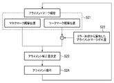
そして、2層目以降のワークWの露光においては、図8に示すように、CCDカメラ30によりマスクMのアライメントマークMaとワークWのアライメントマークWaとを、同時に観測する(ステップS21)。その際、CCDカメラ30により観測されるワーク側のアライメントマークWaに対して、記憶部91に記憶されている初期ずれ成分(ステップS22)をオフセットして得られるワーク側の補正アライメントマークを使用し、マスクMのアライメントマークMaとの間でアライメント補正量を決定する(ステップS23)。その後、不図示のマスク駆動部によりマスクステージ(マスク支持部)1に保持されているマスクMを移動してアライメント調整する(ステップS24)。
Then, in the exposure of the work W on the second and subsequent layers, as shown in FIG. 8, the alignment mark Ma of the mask M and the alignment mark Wa of the work W are simultaneously observed by the CCD camera 30 (step S21). At that time, the correction alignment mark on the work side obtained by offsetting the initial deviation component (step S22) stored in the
これにより、図9(a)に示すように、初期ずれ成分だけずれて観測されるワークWのアライメントマークWaに対して、初期ずれ成分をオフセットしてアライメント調整することにより、制御装置90内では、図9(b)に示すように、マスクMのアライメントマークMaとワークWのアライメントマークWaとが一致した状態となるようにアライメント調整を行うことができる。
As a result, as shown in FIG. 9A, the initial deviation component is offset and the alignment is adjusted with respect to the alignment mark Wa of the work W observed by shifting only the initial deviation component in the
なお、実際には、ミラー変形ユニットに起因する誤差、アライメント動作による誤差や、ワークWを露光処理する際の、ワークの温度変化による伸長、吸着状態の変化、ワークの特性等によりワークW固有の歪がさらに含まれている。このため、実際の露光において観測される各マークの位置は、初期ずれ成分をオフセットしてアライメント調整しても全てのマスク側のアライメントマークとワーク側の補正アライメントマークとが一致することはなく、マスク側のアライメントマークとワーク側のアライメントマークのずれ量の合計が最小となるようにアライメント調整が行われる。 Actually, it is peculiar to the work W due to the error caused by the mirror deformation unit, the error due to the alignment operation, the elongation due to the temperature change of the work, the change of the adsorption state, the characteristics of the work, etc. when the work W is exposed. Further distortion is included. Therefore, the position of each mark observed in the actual exposure does not match the alignment mark on the mask side and the correction alignment mark on the work side even if the initial deviation component is offset and the alignment is adjusted. Alignment adjustment is performed so that the total amount of deviation between the alignment mark on the mask side and the alignment mark on the work side is minimized.
このため、第1実施形態では、マスク側のアライメントマークとワーク側の補正アライメントマークとの各位置でのずれ量に基づいて、ワークWごとに各ミラー変形ユニット70のモータを駆動することで、平面ミラー68をさらにミラー曲げ補正する。これによって、ワークW固有の歪によるずれ量も取り除いて、2層目以降のワークWの露光を行うことができる。
Therefore, in the first embodiment, the motor of each
以上説明したように、本実施形態の近接露光装置PE及び近接露光方法によれば、1層目のマスクMのパターンを露光する際におけるワークWに照射される露光光の主光線ELの角度と、マスクM及びワークW間のギャップとから計算される、ワークW側のアライメントマークWaの初期ずれ成分を記憶し、2層目以降のマスクMのパターンを露光する際、CCDカメラ30により観測されるワークW側のアライメントマークWaに対して初期ずれ成分をオフセットして得られたワークW側の補正アライメントマークと、マスクM側のアライメントマークMaとでアライメント調整する。これにより、ミラー曲げに伴う露光光の主光線ELの角度に起因するアラメント誤差を補正してマスクMのパターンを精度よく露光転写することができる。
As described above, according to the proximity exposure apparatus PE and the proximity exposure method of the present embodiment, the angle of the main light EL of the exposure light applied to the work W when exposing the pattern of the mask M of the first layer , The initial deviation component of the alignment mark Wa on the work W side calculated from the gap between the mask M and the work W is stored, and is observed by the
また、本実施形態では、2層目以降のマスクMのパターンを露光する際、マスク側のアライメントマークMaとワーク側の補正アライメントマークとの各位置でのずれ量に基づいて、ミラー変形ユニット70を駆動して平面ミラー68の曲率を補正するので、ワークW固有の歪によるずれ量も取り除いて、2層目以降のワークWの露光精度をさらに向上することができる。
Further, in the present embodiment, when the pattern of the mask M of the second and subsequent layers is exposed, the
(第2実施形態)
次に、本発明の第2実施形態に係る近接露光装置及び近接露光方法について、図10及び図11を参照して説明する。なお、本実施形態は、平面ミラー68がミラー移動機構をさらに備える点において、及び、ミラーの制御方法において、第1実施形態のものと異なる。(Second Embodiment)
Next, the proximity exposure apparatus and the proximity exposure method according to the second embodiment of the present invention will be described with reference to FIGS. 10 and 11. The present embodiment is different from that of the first embodiment in that the
第2実施形態では、ミラー変形ユニット70を備えた平面ミラー68は、該平面ミラー68に対して垂直方向にそれぞれ移動可能な複数(本実施形態では、4つ)のミラー移動機構80をさらに備える。図10に示すように、複数のミラー移動ユニット80は、ミラー変形ユニット保持枠71の4箇所の隅部にそれぞれ取り付けられる。複数のミラー移動ユニット80は、例えば、平面ミラー68の全体をX方向に対して、又はY方向に対して、或いはX,Y両方向に対して傾けて、光源からの主光線の角度を変えるようにして駆動される。
In the second embodiment, the
ここで、第1実施形態と同様にして、2層目以降のマスクのパターンを露光する際、マスク側のアライメントマークMaとワーク側の補正アライメントマークとの各位置でのずれ量を、Pi=(Δxi,Δyi)とする。ただし、i=1,2,・・・,N
ここで、各位置でのずれ量の平均ずれ量Gは、次式で表される。Here, in the same manner as in the first embodiment, when the mask pattern of the second and subsequent layers is exposed, the amount of deviation between the alignment mark Ma on the mask side and the correction alignment mark on the work side at each position is set to Pi =. Let it be (Δxi, Δyi). However, i = 1, 2, ..., N
Here, the average deviation amount G of the deviation amount at each position is expressed by the following equation.

したがって、本実施形態では、まず、平均ずれ量Gのx成分、y成分に基づいてそれぞれミラー移動機構80を駆動して、平面ミラー68の傾きを変更する。例えば、平均ずれ量Gがx方向にδ(μm)ずれていたとすると、露光ギャップをgap(μm)とすれば、補正角θは、以下の式で表わされる。
Therefore, in the present embodiment, first, the

一方、回転させるミラーのx方向に対応する辺の長さがL(mm)とすると、平均ずれ量Gだけ主光線を傾けるには、A=Ltan(θ/2)となり、このA(mm)だけ、平面ミラー68の辺を動かせばよい。例えば、gap=200μm、δ=1μm、L=2000mmの時、A=5mmとなる。
On the other hand, assuming that the length of the side corresponding to the x direction of the mirror to be rotated is L (mm), A = Ltan (θ / 2) to tilt the main ray by the average deviation amount G, and this A (mm). Only the sides of the
なお、平面ミラー68をAだけ傾ける際には、図11(a)に示すように、x方向の一方のミラー移動機構80のみを動かしてもよいし、図11(b)に示すように、x方向の両側のミラー移動機構80を逆方向に均等にA/2ずつ動かしてもよい。
When tilting the
さらに、各位置でのずれ量Piと平均ずれ量Gとの差分Ai=Pi-Gを算出して、この差分に基づいてミラー変形ユニット70によって平面ミラー68の曲率を補正する。
Further, the difference Ai = Pi—G between the deviation amount Pi and the average deviation amount G at each position is calculated, and the curvature of the
したがって、本実施形態では、2層目以降の前記マスクのパターンを露光する際、マスク側のアライメントマークMaとワーク側の補正アライメントマークとの各位置でのずれ量Piに基づいて、平均ずれ量Gを算出し、該平均ずれ量Gに基づいてミラー移動機構80によって平面ミラー68の傾きを変更すると共に、各位置でのずれ量Piと平均ずれ量Gとの差分Aiに基づいてミラー変形ユニット70によって平面ミラー68の曲率を補正する。これにより、ワークW固有の歪によるずれ量も取り除いて、2層目以降のワークWの露光精度をさらに向上することができると共に、ミラー変形ユニット70のストロークを小さく設定することができ、平面ミラー68の曲げを抑えることができる。
その他の構成及び作用については、第1実施形態のものと同一又は同等である。Therefore, in the present embodiment, when the pattern of the mask on the second and subsequent layers is exposed, the average deviation amount is based on the deviation amount Pi at each position between the alignment mark Ma on the mask side and the correction alignment mark on the work side. G is calculated, the inclination of the
Other configurations and operations are the same as or equivalent to those of the first embodiment.
(第3実施形態)
次に、本発明の第3実施形態に係る近接露光装置及び近接露光方法について、図12~図14を参照して説明する。なお、本実施形態では、ミラーの制御手法において、第1及び第2実施形態のものと異なる。(Third Embodiment)
Next, the proximity exposure apparatus and the proximity exposure method according to the third embodiment of the present invention will be described with reference to FIGS. 12 to 14. In this embodiment, the mirror control method is different from that of the first and second embodiments.
上述したように、ワーク側のアライメントマークWaには、ワークW固有の歪によるずれ成分も含まれてしまうため、本実施形態においても、2層目以降のワークWの露光に当たっては、このずれ成分によるずれ量を補正する。 As described above, the alignment mark Wa on the work side also includes a deviation component due to the strain peculiar to the work W. Therefore, even in this embodiment, this deviation component is used when the work W of the second and subsequent layers is exposed. Corrects the amount of deviation due to.
2層目以降のワークWの露光に当たっては、観測されるワーク側のアライメントマークWaには、上述したミラー曲げ補正による初期ずれ成分Aの他、ワークW固有の歪によるずれ成分Bが含まれている。例えば、1箇所のマーク観測位置に着目すると、図14(a)~(c)に示すように、観測されるワーク側のアライメントマークWaは、ミラー曲げ補正による初期ずれ成分Aをオフセットすると、ワーク側の補正アライメントマークWa´が与えられ、この中に、ワークW固有の歪によるずれ成分Bが含まれている。そしてずれ成分Bを含むワーク側の補正アライメントマークWa´(Wa1´,Wa2´,Wa3´)の位置は、図14(a)~(c)に示すように、ワークWごとに異なる。 In the exposure of the work W of the second and subsequent layers, the observed alignment mark Wa on the work side includes the deviation component B due to the distortion peculiar to the work W in addition to the initial deviation component A due to the mirror bending correction described above. There is. For example, focusing on the mark observation position at one place, as shown in FIGS. 14 (a) to 14 (c), the observed alignment mark Wa on the work side is offset by offsetting the initial deviation component A due to the mirror bending correction. The correction alignment mark Wa'on the side is given, and the deviation component B due to the distortion peculiar to the work W is included in this. The positions of the correction alignment marks Wa'(Wa1', Wa2', Wa3') on the work side including the deviation component B are different for each work W as shown in FIGS. 14A to 14C.
本実施形態では、このワーク側の補正アライメントマークWa´に対して、露光する際のマスク側のアライメントマークMaとの位置ずれ成分を、所定数のワーク(図14では、3つのワーク)を露光した際に平均化して、ひずみ起因ずれ成分Cとして記録する(図14(d)参照)。そして、ひずみ起因ずれ成分Cに基づいて、ミラー変形ユニット70によって平面ミラー68の曲率を補正する。
In the present embodiment, a predetermined number of works (three works in FIG. 14) are exposed to the position deviation component from the alignment mark Ma on the mask side at the time of exposure to the correction alignment mark Wa'on the work side. When this is done, it is averaged and recorded as the strain-induced deviation component C (see FIG. 14 (d)). Then, the curvature of the
図12は、アライメントマークの初期ずれ成分を補正し、さらにワーク固有の歪によるずれ成分を補正して2層目以降のワークを露光する手順を示すフローチャートである。図12に示すように、CCDカメラ30によりマスクMのアライメントマークMaとワークWのアライメントマークWaとを、同時に観測し(ステップS31)、マスクMのアライメントマークMaに対して、記憶部91に記憶されている初期ずれ成分をオフセットして補助アライメントマークWa´を求める(ステップS32)。
FIG. 12 is a flowchart showing a procedure for exposing the work of the second and subsequent layers by correcting the initial deviation component of the alignment mark and further correcting the deviation component due to the strain peculiar to the work. As shown in FIG. 12, the alignment mark Ma of the mask M and the alignment mark Wa of the work W are simultaneously observed by the CCD camera 30 (step S31), and the alignment mark Ma of the mask M is stored in the
次いで、ワーク側の補正アライメントマークWa´と、マスクMのアライメントマークMaとを使用してアライメント調整する(ステップS33)。このとき、アライメント調整量が許容範囲より大きい場合は、マスクステージ(マスク支持部)1を移動(ステップS34)してステップS31に戻る。アライメント調整量が許容範囲より小さい場合は、観測されるアライメントマークWaに対して初期ずれ成分をオフセットしてワークW固有の歪によるずれ成分Bを算出する(ステップS35)。複数枚のワークWを露光した場合には、図14(d)に示すように、各ワークW(図14では3枚のワークW)固有の歪によるずれ成分Bの平均値(ひずみ起因ずれ成分C)を算出し(ステップS36)、これをアライメントマーク基準位置として補正する(ステップS37)。 Next, the alignment is adjusted using the correction alignment mark Wa'on the work side and the alignment mark Ma of the mask M (step S33). At this time, if the alignment adjustment amount is larger than the allowable range, the mask stage (mask support portion) 1 is moved (step S34) and the process returns to step S31. When the alignment adjustment amount is smaller than the allowable range, the initial deviation component is offset with respect to the observed alignment mark Wa, and the deviation component B due to the strain peculiar to the work W is calculated (step S35). When a plurality of workpieces W are exposed, as shown in FIG. 14D, the average value of the displacement component B due to the strain peculiar to each work W (three workpieces W in FIG. 14) (strain-induced displacement component). C) is calculated (step S36), and this is corrected as the alignment mark reference position (step S37).
そして、アライメントマークWaの位置からパターン補正位置の補正変換係数を算出し(ステップS38)、露光パターン補正量を算出して(ステップS39)、平面ミラー68の形状を決定する(ステップS40)。次いで、得られた平面ミラー68の形状を達成するためのモータ74の作動範囲が、リミットを超えているか否かを判別する(ステップS41)。そして、モータ74の作動範囲がリミットを超えている場合には、これ以上の平面ミラー68の形状修正は困難であるので、ステップS45で露光転写する。
Then, the correction conversion coefficient of the pattern correction position is calculated from the position of the alignment mark Wa (step S38), the exposure pattern correction amount is calculated (step S39), and the shape of the
一方、モータ74の作動範囲がリミットを超えていない場合には、モータ74のさらなる移動分(差分)を算出して(ステップS42)、その差分だけモータ74を作動(ステップS43)させて平面ミラー68の形状を変形(ステップS44)して、マスクMのパターンをワークWに露光転写する(ステップS45)。そして、露光が終了した後(ステップS46)、ワークステージ(ワーク支持部)2を次の露光位置に移動し(ステップS47)、モータ74を設定ポジションに移動して(ステップS48)、ステップS31に戻り、同様の動作を繰り返し行う。
On the other hand, when the operating range of the
以上説明したように、本実施形態の近接露光装置PE及び近接露光方法によれば、2層目以降の所定の層におけるマスクMのパターンを露光する際、ワーク側の補正アライメントマークWa´に対して、露光する際のマスク側のアライメントマークMaとの位置ずれ成分を、所定数のワークWを露光した際に平均化してひずみ起因ずれ成分Cとして記録し、ひずみ起因ずれ成分Cに基づいて、ミラー変形ユニット70によって平面ミラー68の曲率を補正する。これにより、ワークW固有の歪に起因するずれ成分Bを補正してマスクMのパターンを精度よく露光転写することができる。
As described above, according to the proximity exposure apparatus PE and the proximity exposure method of the present embodiment, when the pattern of the mask M in the second and subsequent layers is exposed, the correction alignment mark Wa'on the work side is contacted. Then, the position deviation component from the alignment mark Ma on the mask side at the time of exposure is averaged when a predetermined number of works W are exposed and recorded as the strain-induced deviation component C, and based on the strain-induced deviation component C, The curvature of the
なお、ミラー変形ユニットに起因する誤差、アライメント動作による誤差を特定することができる場合には、ワーク側の補正アライメントマークWa´は、初期ひずみ成分に加え、これらの誤差成分もオフセットして与えることができる。 If the error caused by the mirror deformation unit and the error due to the alignment operation can be specified, the correction alignment mark Wa'on the work side should be given by offsetting these error components in addition to the initial strain component. Can be done.
尚、本発明は、前述した実施形態に限定されるものではなく、適宜、変形、改良、等が可能である。 The present invention is not limited to the above-described embodiment, and can be appropriately modified, improved, and the like.
例えば、上記実施形態では、ワーク固有の歪に起因するずれ量の補正は、ミラー曲げに伴う露光光の主光線の角度に起因するアラメント誤差の補正と独立して行われてもよい。即ち、本発明の近接露光装置及び近接露光方法は、2層目以降の所定の層におけるマスクのパターンを露光する際、ワーク側のアライメントマークに対して、露光する際のマスク側のアライメントマークとの位置ずれ成分を、所定数のワークを露光した際に平均化してひずみ起因ずれ成分として記録し、ひずみ起因ずれ成分に基づいて、ミラー曲げ機構によって反射鏡の曲率を補正する。これにより、ワーク固有の歪に起因するずれ量を補正してマスクのパターンを精度よく露光転写することができる 。 For example, in the above embodiment, the correction of the deviation amount due to the strain peculiar to the work may be performed independently of the correction of the allament error due to the angle of the main ray of the exposure light due to the mirror bending. That is, in the proximity exposure apparatus and the proximity exposure method of the present invention, when the mask pattern in the second and subsequent layers is exposed, the alignment mark on the work side is used as the alignment mark on the mask side when the exposure is performed. When a predetermined number of workpieces are exposed, the misalignment component is recorded as a strain-induced displacement component, and the curvature of the reflecting mirror is corrected by the mirror bending mechanism based on the strain-induced displacement component. As a result, it is possible to correct the amount of deviation caused by the distortion peculiar to the work and transfer the mask pattern by exposure with high accuracy.
本発明を詳細にまた特定の実施態様を参照して説明したが、本発明の精神と範囲を逸脱することなく様々な変更や修正を加えることができることは当業者にとって明らかである。
本出願は、2016年12月8日出願の日本特許出願2016-238738に基づくものであり、その内容はここに参照として取り込まれる。Although the present invention has been described in detail and with reference to specific embodiments, it will be apparent to those skilled in the art that various changes and modifications can be made without departing from the spirit and scope of the invention.
This application is based on Japanese patent application 2016-238738 filed on December 8, 2016, the contents of which are incorporated herein by reference.
1 マスクステージ(マスク支持部)
2 ワークステージ(ワーク支持部)
3 照明光学系
30 CCDカメラ(アライメントカメラ)
60 マルチランプユニット(光源)
65 オプティカルインテグレータ
68 平面ミラー(反射鏡)
70 ミラー変形ユニット(ミラー曲げ機構)
90 制御装置
91 記憶部
EL 主光線
M マスク
Ma マスク側のアライメントマーク
PE 近接露光装置
W ワーク
Wa ,Wa1,Wa2,Wa3 ワーク側のアライメントマーク
Wa´,Wa1´,Wa2´,Wa3´ ワーク側の補助アライメントマーク1 Mask stage (mask support)
2 Work stage (work support part)
3 Illumination
60 Multi-lamp unit (light source)
65
70 Mirror deformation unit (mirror bending mechanism)
90
Claims (10)
マスクを支持するマスク支持部と、
光源、インテグレータ、及び光源からの露光光を反射する複数の反射鏡を有する照明光学系と、
を備え、前記光源からの露光光を前記マスクを介して前記ワークに照射して前記マスクのパターンを前記ワークに転写する近接露光装置であって、
前記複数の反射鏡の内の少なくとも1つの前記反射鏡は、前記反射鏡の曲率を補正可能なミラー曲げ機構を有し、
マスク側のアライメントマークと、ワーク側のアライメントマークとを撮像可能なアライメントカメラと、
1層目の前記マスクのパターンを露光する際における前記ワークに照射される前記露光光の主光線の角度と、前記マスク及び前記ワーク間のギャップとから計算される、前記ワーク側のアライメントマークの初期ずれ成分を記憶する記憶部と、
2層目以降の前記マスクのパターンを露光する際、前記アライメントカメラにより観測される前記ワーク側のアライメントマークに対して前記初期ずれ成分をオフセットして得られたワーク側の補正アライメントマークと、前記マスク側のアライメントマークとでアライメント調整する制御装置と、
を備えることを特徴とする近接露光装置。 The work support part that supports the work and the work support
The mask support part that supports the mask and
Illumination optics with a light source, an integrator, and multiple reflectors that reflect the exposure light from the light source.
A proximity exposure apparatus that irradiates the work with exposure light from the light source through the mask and transfers the pattern of the mask to the work.
At least one of the plurality of reflectors has a mirror bending mechanism capable of correcting the curvature of the reflector.
An alignment camera that can capture the alignment mark on the mask side and the alignment mark on the work side,
The alignment mark on the work side calculated from the angle of the main light beam of the exposure light applied to the work when the pattern of the mask on the first layer is exposed and the gap between the mask and the work. A storage unit that stores the initial deviation component and
When exposing the pattern of the mask on the second and subsequent layers, the correction alignment mark on the work side obtained by offsetting the initial deviation component with respect to the alignment mark on the work side observed by the alignment camera, and the above-mentioned correction alignment mark on the work side. A control device that adjusts the alignment with the alignment mark on the mask side,
A proximity exposure apparatus characterized by comprising.
前記2層目以降の所定の層における前記マスクのパターンを露光する際、当該所定の層の前記マスクのパターンを露光する際のアライメントにおける、前記マスク側のアライメントマークと前記ワーク側の補正アライメントマークとの各位置でのずれ量に基づいて、平均ずれ量を算出し、該平均ずれ量に基づいて前記ミラー移動機構によって前記反射鏡の傾きを変更すると共に、前記各位置でのずれ量と前記平均ずれ量との差分に基づいて前記ミラー曲げ機構によって前記反射鏡の曲率を補正することを特徴とする請求項1に記載の近接露光装置。 The reflecting mirror provided with the mirror bending mechanism is further provided with a mirror moving mechanism capable of moving in the direction perpendicular to the reflecting mirror.
When exposing the pattern of the mask in the predetermined layer after the second layer, the alignment mark on the mask side and the correction alignment mark on the work side in the alignment when exposing the pattern of the mask in the predetermined layer. The average deviation amount is calculated based on the deviation amount at each position, and the inclination of the reflector is changed by the mirror moving mechanism based on the average deviation amount, and the deviation amount at each position and the above. The proximity exposure device according to claim 1, wherein the mirror bending mechanism corrects the curvature of the reflecting mirror based on the difference from the average deviation amount.
前記制御装置は、前記ひずみ起因ずれ成分に基づいて、前記ミラー曲げ機構によって前記反射鏡の曲率を補正することを特徴とする請求項1に記載の近接露光装置。 The storage unit is the work side when the pattern of the mask in the predetermined layer after the second layer is exposed, and the pattern of the mask in the predetermined layer is exposed to a predetermined number of works in advance. The misalignment component with respect to the correction alignment mark on the mask side is averaged and recorded as a strain-induced misalignment component.
The proximity exposure apparatus according to claim 1, wherein the control device corrects the curvature of the reflecting mirror by the mirror bending mechanism based on the strain-induced displacement component.
マスクを支持するマスク支持部と、
光源、インテグレータ、及び光源からの露光光を反射する複数の反射鏡を有する照明光学系と、
を備え、前記光源からの露光光を前記マスクを介して前記ワークに照射して前記マスクのパターンを前記ワークに転写する近接露光装置であって、
前記複数の反射鏡の内の少なくとも1つの前記反射鏡は、前記反射鏡の曲率を補正可能なミラー曲げ機構を有し、
マスク側のアライメントマークと、ワーク側のアライメントマークとを撮像可能なアライメントカメラを備え、
2層目以降の所定の層における前記マスクのパターンを露光する際、当該所定の層の前記マスクのパターンの露光を予め所定数のワークに対して行った際における前記ワーク側のアライメントマークに対する、前記マスク側のアライメントマークとの位置ずれ成分を平均化してひずみ起因ずれ成分として記録する記憶部と、
前記ひずみ起因ずれ成分に基づいて、前記ミラー曲げ機構によって前記反射鏡の曲率を補正する制御部と、
を備えることを特徴とする近接露光装置。 The work support part that supports the work and the work support
The mask support part that supports the mask and
Illumination optics with a light source, an integrator, and multiple reflectors that reflect the exposure light from the light source.
A proximity exposure apparatus that irradiates the work with exposure light from the light source through the mask to transfer the pattern of the mask to the work.
At least one of the plurality of reflectors has a mirror bending mechanism capable of correcting the curvature of the reflector.
Equipped with an alignment camera that can capture the alignment mark on the mask side and the alignment mark on the work side.
When the pattern of the mask on the second and subsequent layers is exposed, the alignment mark on the work side when the pattern of the mask on the predetermined layer is exposed to a predetermined number of works in advance is matched. A storage unit that averages the misalignment component with the alignment mark on the mask side and records it as a strain-induced misalignment component.
A control unit that corrects the curvature of the reflecting mirror by the mirror bending mechanism based on the strain-induced deviation component.
A proximity exposure apparatus characterized by comprising.
マスクを支持するマスク支持部と、
光源、インテグレータ、及び光源からの露光光を反射する複数の反射鏡を有する照明光学系と、
前記複数の反射鏡の内の少なくとも1つの前記反射鏡は、前記反射鏡の曲率を補正可能なミラー曲げ機構を有し、
マスク側のアライメントマークと、ワーク側のアライメントマークとを撮像可能なアライメントカメラと、
を備える近接露光装置を用いて、前記光源からの露光光を前記マスクを介して前記ワークに照射して前記マスクのパターンを前記ワークに転写する近接露光方法であって、
1層目のマスクのパターンを露光する際における前記ワークに照射される前記露光光の主光線の角度と、前記マスク及び前記ワーク間のギャップとから計算される、前記ワーク側のアライメントマークの初期ずれ成分を記憶する工程と、
2層目以降の前記マスクのパターンを露光する際、前記アライメントカメラにより観測される前記ワーク側のアライメントマークに対して前記初期ずれ成分をオフセットして得られたワーク側の補正アライメントマークと、前記マスク側のアライメントマークとでアライメント調整する工程と、
を備えることを特徴とする近接露光方法。 The work support part that supports the work and the work support
The mask support part that supports the mask and
Illumination optics with a light source, an integrator, and multiple reflectors that reflect the exposure light from the light source.
At least one of the plurality of reflectors has a mirror bending mechanism capable of correcting the curvature of the reflector.
An alignment camera that can capture the alignment mark on the mask side and the alignment mark on the work side,
A proximity exposure method in which an exposure light from the light source is applied to the work through the mask to transfer the pattern of the mask to the work by using a proximity exposure device.
The initial alignment mark on the work side calculated from the angle of the main light beam of the exposure light applied to the work when the pattern of the first layer mask is exposed and the gap between the mask and the work. The process of memorizing the deviation component and
When exposing the pattern of the mask on the second and subsequent layers, the correction alignment mark on the work side obtained by offsetting the initial deviation component with respect to the alignment mark on the work side observed by the alignment camera, and the above-mentioned correction alignment mark on the work side. The process of adjusting the alignment with the alignment mark on the mask side,
A proximity exposure method characterized by comprising.
前記2層目以降の所定の層における前記マスクのパターンを露光する際、当該所定の層の前記マスクのパターンを露光する際のアライメントにおける、前記マスク側のアライメントマークと前記ワーク側の補正アライメントマークとの各位置でのずれ量に基づいて、平均ずれ量を算出し、該平均ずれ量に基づいて前記ミラー移動機構によって前記反射鏡の傾きを変更すると共に、前記各位置でのずれ量と前記平均ずれ量との差分に基づいて前記ミラー曲げ機構によって前記反射鏡の曲率を補正することを特徴とする請求項6に記載の近接露光方法。 The proximity exposure apparatus further comprises a mirror moving mechanism capable of moving the reflecting mirror provided with the mirror bending mechanism in a direction perpendicular to the reflecting mirror.
When exposing the pattern of the mask in the predetermined layer after the second layer, the alignment mark on the mask side and the correction alignment mark on the work side in the alignment when exposing the pattern of the mask in the predetermined layer. The average deviation amount is calculated based on the deviation amount at each position, and the inclination of the reflector is changed by the mirror moving mechanism based on the average deviation amount, and the deviation amount at each position and the above. The proximity exposure method according to claim 6, wherein the curvature of the reflecting mirror is corrected by the mirror bending mechanism based on the difference from the average deviation amount.
前記ひずみ起因ずれ成分に基づいて、前記ミラー曲げ機構によって前記反射鏡の曲率を補正する工程と、
を備えることを特徴とする請求項6に記載の近接露光方法。 When the pattern of the mask on the second and subsequent layers is exposed, the correction alignment mark on the work side is used when the pattern of the mask on the predetermined layer is exposed to a predetermined number of works in advance . On the other hand , a step of averaging the misalignment component with the alignment mark on the mask side and recording it as a strain-induced misalignment component.
A step of correcting the curvature of the reflecting mirror by the mirror bending mechanism based on the strain-induced deviation component, and
The proximity exposure method according to claim 6, further comprising.
マスクを支持するマスク支持部と、
光源、インテグレータ、及び光源からの露光光を反射する複数の反射鏡を有する照明光学系と、
前記複数の反射鏡の内の少なくとも1つの前記反射鏡は、前記反射鏡の曲率を補正可能なミラー曲げ機構を有し、
マスク側のアライメントマークと、ワーク側のアライメントマークとを撮像可能なアライメントカメラと、
を備える近接露光装置を用いて、前記光源からの露光光を前記マスクを介して前記ワークに照射して前記マスクのパターンを前記ワークに転写する近接露光方法であって、
2層目以降の所定の層における前記マスクのパターンを露光する際、当該所定の層の前記マスクのパターンの露光を予め所定数のワークに対して行った際における前記ワーク側のアライメントマークに対する、前記マスク側のアライメントマークとの位置ずれ成分を平均化してひずみ起因ずれ成分として記録する工程と、
前記ひずみ起因ずれ成分に基づいて、前記ミラー曲げ機構によって前記反射鏡の曲率を補正する工程と、
を備えることを特徴とする近接露光方法。 The work support part that supports the work and the work support
The mask support part that supports the mask and
Illumination optics with a light source, an integrator, and multiple reflectors that reflect the exposure light from the light source.
At least one of the plurality of reflectors has a mirror bending mechanism capable of correcting the curvature of the reflector.
An alignment camera that can capture the alignment mark on the mask side and the alignment mark on the work side,
A proximity exposure method in which an exposure light from the light source is applied to the work through the mask to transfer the pattern of the mask to the work by using a proximity exposure device.
When the pattern of the mask on the second and subsequent layers is exposed, the alignment mark on the work side when the pattern of the mask on the predetermined layer is exposed to a predetermined number of works in advance is matched. The step of averaging the misalignment component with the alignment mark on the mask side and recording it as a strain-induced misalignment component.
A step of correcting the curvature of the reflecting mirror by the mirror bending mechanism based on the strain-induced deviation component, and
A proximity exposure method characterized by comprising.
Applications Claiming Priority (3)
| Application Number | Priority Date | Filing Date | Title |
|---|---|---|---|
| JP2016238738 | 2016-12-08 | ||
| JP2016238738 | 2016-12-08 | ||
| PCT/JP2017/043825 WO2018105658A1 (en) | 2016-12-08 | 2017-12-06 | Proximity exposure apparatus and proximity exposure method |
Publications (2)
| Publication Number | Publication Date |
|---|---|
| JPWO2018105658A1 JPWO2018105658A1 (en) | 2019-10-24 |
| JP7088552B2 true JP7088552B2 (en) | 2022-06-21 |
Family
ID=62492235
Family Applications (1)
| Application Number | Title | Priority Date | Filing Date |
|---|---|---|---|
| JP2018555042A Expired - Fee Related JP7088552B2 (en) | 2016-12-08 | 2017-12-06 | Proximity exposure equipment and proximity exposure method |
Country Status (5)
| Country | Link |
|---|---|
| JP (1) | JP7088552B2 (en) |
| KR (1) | KR102477736B1 (en) |
| CN (1) | CN110062914B (en) |
| TW (1) | TWI748017B (en) |
| WO (1) | WO2018105658A1 (en) |
Citations (7)
| Publication number | Priority date | Publication date | Assignee | Title |
|---|---|---|---|---|
| JP2000081708A (en) | 1998-09-03 | 2000-03-21 | Toray Ind Inc | Exposure apparatus and plasma display manufacturing method using the same |
| JP2003224058A (en) | 2002-01-30 | 2003-08-08 | Nsk Ltd | Exposure apparatus and exposure method |
| JP2006128346A (en) | 2004-10-28 | 2006-05-18 | Tokyo Seimitsu Co Ltd | Exposure apparatus, foreign matter detection method, foreign matter position identification method, and exposure method |
| JP2006293197A (en) | 2005-04-14 | 2006-10-26 | Sanee Giken Kk | Exposure light source using semiconductor laser |
| WO2007145038A1 (en) | 2006-06-14 | 2007-12-21 | Nsk Ltd. | Proximity aligner and proximity exposure method |
| JP2011028122A (en) | 2009-07-28 | 2011-02-10 | Nsk Ltd | Exposure apparatus and exposure method |
| JP2012155086A (en) | 2011-01-25 | 2012-08-16 | Nsk Technology Co Ltd | Exposure device and exposure method |
Family Cites Families (7)
| Publication number | Priority date | Publication date | Assignee | Title |
|---|---|---|---|---|
| JPH07106230A (en) * | 1993-10-07 | 1995-04-21 | Nikon Corp | Proximity exposure system |
| WO2007013140A1 (en) * | 2005-07-26 | 2007-02-01 | Fujitsu Limited | Aligning method |
| JP5166916B2 (en) * | 2008-03-04 | 2013-03-21 | キヤノン株式会社 | Apparatus for superimposing patterns and device manufacturing method |
| US20110027542A1 (en) * | 2009-07-28 | 2011-02-03 | Nsk Ltd. | Exposure apparatus and exposure method |
| JP5597031B2 (en) * | 2010-05-31 | 2014-10-01 | キヤノン株式会社 | Lithographic apparatus and article manufacturing method |
| JP2015026644A (en) * | 2013-07-24 | 2015-02-05 | Nskテクノロジー株式会社 | Proximity exposure device and proximity exposure method |
| JP6574087B2 (en) | 2013-12-09 | 2019-09-11 | 株式会社ブイ・テクノロジー | Exposure apparatus, exposure method, and reflecting mirror with mirror bending mechanism |
-
2017
- 2017-12-06 CN CN201780076227.6A patent/CN110062914B/en active Active
- 2017-12-06 WO PCT/JP2017/043825 patent/WO2018105658A1/en not_active Ceased
- 2017-12-06 JP JP2018555042A patent/JP7088552B2/en not_active Expired - Fee Related
- 2017-12-06 KR KR1020197016160A patent/KR102477736B1/en active Active
- 2017-12-08 TW TW106143112A patent/TWI748017B/en active
Patent Citations (7)
| Publication number | Priority date | Publication date | Assignee | Title |
|---|---|---|---|---|
| JP2000081708A (en) | 1998-09-03 | 2000-03-21 | Toray Ind Inc | Exposure apparatus and plasma display manufacturing method using the same |
| JP2003224058A (en) | 2002-01-30 | 2003-08-08 | Nsk Ltd | Exposure apparatus and exposure method |
| JP2006128346A (en) | 2004-10-28 | 2006-05-18 | Tokyo Seimitsu Co Ltd | Exposure apparatus, foreign matter detection method, foreign matter position identification method, and exposure method |
| JP2006293197A (en) | 2005-04-14 | 2006-10-26 | Sanee Giken Kk | Exposure light source using semiconductor laser |
| WO2007145038A1 (en) | 2006-06-14 | 2007-12-21 | Nsk Ltd. | Proximity aligner and proximity exposure method |
| JP2011028122A (en) | 2009-07-28 | 2011-02-10 | Nsk Ltd | Exposure apparatus and exposure method |
| JP2012155086A (en) | 2011-01-25 | 2012-08-16 | Nsk Technology Co Ltd | Exposure device and exposure method |
Also Published As
| Publication number | Publication date |
|---|---|
| CN110062914B (en) | 2021-09-07 |
| TWI748017B (en) | 2021-12-01 |
| CN110062914A (en) | 2019-07-26 |
| JPWO2018105658A1 (en) | 2019-10-24 |
| WO2018105658A1 (en) | 2018-06-14 |
| TW201827943A (en) | 2018-08-01 |
| KR102477736B1 (en) | 2022-12-14 |
| KR20190090804A (en) | 2019-08-02 |
Similar Documents
| Publication | Publication Date | Title |
|---|---|---|
| JP6535197B2 (en) | Exposure apparatus and exposure method | |
| JP6765607B2 (en) | Exposure device, exposure method | |
| CN101101452A (en) | Exposure device | |
| JPWO2019155886A1 (en) | Proximity exposure equipment, proximity exposure method, and light irradiation equipment for proximity exposure equipment | |
| JP6663914B2 (en) | Illumination device for exposure, exposure device and exposure method | |
| CN100559281C (en) | Exposure device and exposure method | |
| KR100849871B1 (en) | Exposure apparatus | |
| JP7088552B2 (en) | Proximity exposure equipment and proximity exposure method | |
| JP2006100590A (en) | Proximity exposure equipment | |
| JP2019109445A (en) | Proximity exposure device and proximity exposure method | |
| JP5473793B2 (en) | Proximity exposure apparatus and gap control method for proximity exposure apparatus | |
| CN105045043B (en) | Exposure device and exposure method | |
| JP2004349494A (en) | Work stage, position measuring method thereof, and exposure apparatus having the same | |
| JP4487688B2 (en) | Step-type proximity exposure system | |
| JP6484853B2 (en) | Reflector unit for exposure apparatus and exposure apparatus | |
| JP2008209632A (en) | Mask mounting method and exposure apparatus unit | |
| JPWO2019059315A1 (en) | Lighting equipment for exposure, exposure equipment and exposure method | |
| JP2007248636A (en) | Mirror fixing structure of position measuring device | |
| JP2007171667A (en) | Exposure equipment | |
| JP6485627B2 (en) | Exposure apparatus and exposure method | |
| JP2008089993A (en) | Method for measuring gap amount of exposure apparatus | |
| JP2016148811A (en) | Exposure device and luminaire | |
| JP2007101882A (en) | Exposure equipment | |
| JP2007140187A (en) | Mask transport and mounting method for exposure equipment |
Legal Events
| Date | Code | Title | Description |
|---|---|---|---|
| A621 | Written request for application examination |
Free format text: JAPANESE INTERMEDIATE CODE: A621 Effective date: 20200911 |
|
| A131 | Notification of reasons for refusal |
Free format text: JAPANESE INTERMEDIATE CODE: A131 Effective date: 20211102 |
|
| A521 | Request for written amendment filed |
Free format text: JAPANESE INTERMEDIATE CODE: A523 Effective date: 20211227 |
|
| TRDD | Decision of grant or rejection written | ||
| A01 | Written decision to grant a patent or to grant a registration (utility model) |
Free format text: JAPANESE INTERMEDIATE CODE: A01 Effective date: 20220510 |
|
| A61 | First payment of annual fees (during grant procedure) |
Free format text: JAPANESE INTERMEDIATE CODE: A61 Effective date: 20220602 |
|
| R150 | Certificate of patent or registration of utility model |
Ref document number: 7088552 Country of ref document: JP Free format text: JAPANESE INTERMEDIATE CODE: R150 |
|
| LAPS | Cancellation because of no payment of annual fees |