JP7071029B2 - Methods and equipment for modularized intake silencer baffles - Google Patents
Methods and equipment for modularized intake silencer baffles Download PDFInfo
- Publication number
- JP7071029B2 JP7071029B2 JP2017169092A JP2017169092A JP7071029B2 JP 7071029 B2 JP7071029 B2 JP 7071029B2 JP 2017169092 A JP2017169092 A JP 2017169092A JP 2017169092 A JP2017169092 A JP 2017169092A JP 7071029 B2 JP7071029 B2 JP 7071029B2
- Authority
- JP
- Japan
- Prior art keywords
- baffle
- silencer
- rod
- portions
- panel
- Prior art date
- Legal status (The legal status is an assumption and is not a legal conclusion. Google has not performed a legal analysis and makes no representation as to the accuracy of the status listed.)
- Active
Links
Images


Classifications
-
- F—MECHANICAL ENGINEERING; LIGHTING; HEATING; WEAPONS; BLASTING
- F02—COMBUSTION ENGINES; HOT-GAS OR COMBUSTION-PRODUCT ENGINE PLANTS
- F02C—GAS-TURBINE PLANTS; AIR INTAKES FOR JET-PROPULSION PLANTS; CONTROLLING FUEL SUPPLY IN AIR-BREATHING JET-PROPULSION PLANTS
- F02C7/00—Features, components parts, details or accessories, not provided for in, or of interest apart form groups F02C1/00 - F02C6/00; Air intakes for jet-propulsion plants
- F02C7/04—Air intakes for gas-turbine plants or jet-propulsion plants
- F02C7/045—Air intakes for gas-turbine plants or jet-propulsion plants having provisions for noise suppression
-
- F—MECHANICAL ENGINEERING; LIGHTING; HEATING; WEAPONS; BLASTING
- F02—COMBUSTION ENGINES; HOT-GAS OR COMBUSTION-PRODUCT ENGINE PLANTS
- F02C—GAS-TURBINE PLANTS; AIR INTAKES FOR JET-PROPULSION PLANTS; CONTROLLING FUEL SUPPLY IN AIR-BREATHING JET-PROPULSION PLANTS
- F02C7/00—Features, components parts, details or accessories, not provided for in, or of interest apart form groups F02C1/00 - F02C6/00; Air intakes for jet-propulsion plants
-
- F—MECHANICAL ENGINEERING; LIGHTING; HEATING; WEAPONS; BLASTING
- F04—POSITIVE - DISPLACEMENT MACHINES FOR LIQUIDS; PUMPS FOR LIQUIDS OR ELASTIC FLUIDS
- F04D—NON-POSITIVE-DISPLACEMENT PUMPS
- F04D29/00—Details, component parts, or accessories
- F04D29/66—Combating cavitation, whirls, noise, vibration or the like; Balancing
- F04D29/661—Combating cavitation, whirls, noise, vibration or the like; Balancing especially adapted for elastic fluid pumps
- F04D29/663—Sound attenuation
-
- G—PHYSICS
- G10—MUSICAL INSTRUMENTS; ACOUSTICS
- G10K—SOUND-PRODUCING DEVICES; METHODS OR DEVICES FOR PROTECTING AGAINST, OR FOR DAMPING, NOISE OR OTHER ACOUSTIC WAVES IN GENERAL; ACOUSTICS NOT OTHERWISE PROVIDED FOR
- G10K11/00—Methods or devices for transmitting, conducting or directing sound in general; Methods or devices for protecting against, or for damping, noise or other acoustic waves in general
- G10K11/16—Methods or devices for protecting against, or for damping, noise or other acoustic waves in general
- G10K11/161—Methods or devices for protecting against, or for damping, noise or other acoustic waves in general in systems with fluid flow
-
- F—MECHANICAL ENGINEERING; LIGHTING; HEATING; WEAPONS; BLASTING
- F05—INDEXING SCHEMES RELATING TO ENGINES OR PUMPS IN VARIOUS SUBCLASSES OF CLASSES F01-F04
- F05D—INDEXING SCHEME FOR ASPECTS RELATING TO NON-POSITIVE-DISPLACEMENT MACHINES OR ENGINES, GAS-TURBINES OR JET-PROPULSION PLANTS
- F05D2240/00—Components
- F05D2240/40—Use of a multiplicity of similar components
-
- F—MECHANICAL ENGINEERING; LIGHTING; HEATING; WEAPONS; BLASTING
- F05—INDEXING SCHEMES RELATING TO ENGINES OR PUMPS IN VARIOUS SUBCLASSES OF CLASSES F01-F04
- F05D—INDEXING SCHEME FOR ASPECTS RELATING TO NON-POSITIVE-DISPLACEMENT MACHINES OR ENGINES, GAS-TURBINES OR JET-PROPULSION PLANTS
- F05D2260/00—Function
- F05D2260/30—Retaining components in desired mutual position
- F05D2260/36—Retaining components in desired mutual position by a form fit connection, e.g. by interlocking
-
- F—MECHANICAL ENGINEERING; LIGHTING; HEATING; WEAPONS; BLASTING
- F05—INDEXING SCHEMES RELATING TO ENGINES OR PUMPS IN VARIOUS SUBCLASSES OF CLASSES F01-F04
- F05D—INDEXING SCHEME FOR ASPECTS RELATING TO NON-POSITIVE-DISPLACEMENT MACHINES OR ENGINES, GAS-TURBINES OR JET-PROPULSION PLANTS
- F05D2260/00—Function
- F05D2260/96—Preventing, counteracting or reducing vibration or noise
Landscapes
- Engineering & Computer Science (AREA)
- Chemical & Material Sciences (AREA)
- Combustion & Propulsion (AREA)
- Mechanical Engineering (AREA)
- General Engineering & Computer Science (AREA)
- Physics & Mathematics (AREA)
- Aviation & Aerospace Engineering (AREA)
- Fluid Mechanics (AREA)
- Acoustics & Sound (AREA)
- Multimedia (AREA)
- Structures Of Non-Positive Displacement Pumps (AREA)
- Exhaust Silencers (AREA)
Description
本明細書に開示される主題は、ガスタービンエンジン用の空気ダクト内の騒音を抑制するためのシステムおよび方法に関する。 The subject matter disclosed herein relates to systems and methods for controlling noise in air ducts for gas turbine engines.
ガスタービンエンジンなどの発電機器は、燃焼プロセスを支援するために大量の吸気の供給を使用することができる。タービンの適切な性能を維持するために、空気が圧縮機で圧縮される前に、吸気をフィルタ処理して不要な塵、水分および他の汚染物質を除去する。吸気ハウジングおよび空気ダクトを通って移動する大量の空気は、大きな騒音を発生させ、吸気ハウジングおよび他の機器の振動を引き起こす可能性がある。さらに、圧縮機のブレード通過周波数および入口抽気加熱システムは、騒音および振動の原因となる可能性がある。タービンエンジンに関しては、エンジンの振動に加えることは一般に望ましくない。このように、吸気ハウジングおよび空気ダクトを通って移動する吸気によって生じる騒音および振動を低減することが望ましい。 Power generation equipment, such as gas turbine engines, can use a large supply of intake air to support the combustion process. To maintain proper turbine performance, the intake air is filtered to remove unwanted dust, moisture and other contaminants before the air is compressed by the compressor. Large amounts of air moving through the intake housing and air ducts can generate loud noises and cause vibrations in the intake housing and other equipment. In addition, the compressor blade passing frequency and inlet bleed heating system can cause noise and vibration. For turbine engines, it is generally not desirable to add to engine vibration. In this way, it is desirable to reduce the noise and vibration caused by the intake air moving through the intake air housing and the air duct.
最初に特許請求する主題の範囲に相応する特定の実施形態を以下に要約する。これらの実施形態は特許請求する主題の範囲を限定しようとするものではなく、むしろ、これらの実施形態は主題の可能性がある形式の概要を提供しようとするものにすぎない。実際、本主題は、以下に記載する実施形態に類似してもよく、あるいは異なってもよい様々な形態を含むことができる。 Specific embodiments that correspond to the scope of the claims first are summarized below. These embodiments do not seek to limit the scope of the claims, but rather these embodiments merely seek to provide an overview of the possible forms of the subject matter. In fact, the subject can include various embodiments that may be similar to or different from the embodiments described below.
第1の実施形態では、システムは、流体流路を有する導管と、流体流路に沿って流体導管内に配置されたサイレンサバッフルと、を含み、サイレンサバッフルは、嵌合インターロック構造を介して互いに結合された複数のバッフル部のうちの少なくとも2つを有する。 In a first embodiment, the system comprises a conduit having a fluid flow path and a silencer baffle disposed in the fluid conduit along the fluid flow path, the silencer baffle via a mating interlock structure. It has at least two of a plurality of baffle portions coupled to each other.
第2の実施形態では、システムは、流体流路に沿って流体導管に装着するように構成されたサイレンサバッフルの第1のバッフル部を含み、第1のバッフル部は、嵌合インターロック構造を介してサイレンサバッフルの第2のバッフル部と互いに結合される。 In a second embodiment, the system includes a first baffle portion of a silencer baffle configured to attach to a fluid conduit along the fluid flow path, the first baffle portion having a mating interlock structure. It is coupled to each other with the second baffle portion of the silencer baffle via.
第3の実施形態では、システムは、流体流路に沿って流体導管に装着するように構成されたサイレンサバッフルの第1のバッフル部を含み、第1のバッフル部は、サイレンサバッフルの第2のバッフル部と互いに結合されるように構成される。本システムは、第1のバッフル部の第1の支持ロッド通路および第2のバッフル部の第2の支持ロッド通路を貫通して延在するように構成された支持ロッドを含む。 In a third embodiment, the system includes a first baffle portion of a silencer baffle configured to attach to a fluid conduit along the fluid flow path, the first baffle portion being a second baffle portion of the silencer baffle. It is configured to be coupled to the baffle portion. The system includes a support rod configured to extend through a first support rod passage in the first baffle portion and a second support rod passage in the second baffle portion.
本主題のこれらの、ならびに他の特徴、態様および利点は、添付の図面を参照しつつ以下の詳細な説明を読めば、よりよく理解されよう。添付の図面では、図面の全体にわたって、類似する符号は類似する部分を表す。 These, as well as other features, aspects and advantages of this subject, will be better understood by reading the detailed description below with reference to the accompanying drawings. In the accompanying drawings, similar symbols represent similar parts throughout the drawing.
以下で、本主題の1つまたは複数の具体的な実施形態を説明する。これらの実施形態の簡潔な説明を提供しようと努力しても、実際の実施のすべての特徴を本明細書に記載することができるというわけではない。エンジニアリングまたは設計プロジェクトなどの実際の実施の開発においては、開発者の特定の目的を達成するために、例えばシステム関連および事業関連の制約条件への対応など実施に特有の決定を数多くしなければならないし、また、これらの制約条件は実施ごとに異なる可能性があることを理解されたい。さらに、このような開発作業は複雑で時間がかかるかもしれないが、にもかかわらず、この開示の利益を得る当業者にとっては、設計、製作、および製造の日常的な仕事であることが理解されるべきである。 Hereinafter, one or more specific embodiments of the present subject will be described. Efforts to provide a concise description of these embodiments may not be described herein with all the features of the actual practice. In the development of a real-world implementation, such as an engineering or design project, a number of implementation-specific decisions must be made to achieve a developer's specific objectives, such as addressing system-related and business-related constraints. However, it should be understood that these constraints may vary from implementation to implementation. Moreover, it is understood that such development work may be complex and time consuming, but nevertheless is a routine design, manufacture, and manufacturing task for those skilled in the art who benefit from this disclosure. It should be.
本主題の様々な実施形態の要素を導入する場合に、単数の表現および「前記」は1つまたは複数の要素があることを意味するものである。「含む」、「含む」、および「有する」という用語は、包括的なものであって、列挙された要素以外の付加的な要素があり得ることを意味するものである。 When introducing elements of various embodiments of the subject, the singular representation and "above" are meant to have one or more elements. The terms "contain", "contain", and "have" are comprehensive and mean that there may be additional elements other than those listed.
特許請求する主題の実施形態は、ガスタービンエンジンを含む発電システムを含み、システムは、流体(例えば、空気、再循環排気ガスなど)を圧縮機に流すための導管(例えば、吸気もしくは排気ハウジングおよびダクト)を含む。1つまたは複数のサイレンサバッフルは、ハウジングまたはダクト(例えば、吸気または排気)に配置される。サイレンサバッフルは、互いにほぼ直線状に整列した複数のバッフル部を含む。バッフル部は、嵌合インターロック構造などの固定可能な結合部を介して互いに結合される。嵌合インターロック構造は、結合されたときに隣接するバッフル部を互いに固定する雌接合部分および雄接合部分を含むことができる。例えば、嵌合インターロック構造は、嵌合レール部分、嵌合ダブテール接合部、嵌合フックおよびスロット接合部、嵌合ラッチ、またはこれらの任意の組み合わせを含むことができる。2つ以上のバッフル部が組み立てられて、サイレンサバッフルを形成する。サイレンサバッフルのバッフル部は、組み立てられて吸気ハウジングおよび/または空気ダクト内に取り付けられると、複数のロウおよびカラムを形成することができる。バッフル部は、発電システムの吸気部(例えば、吸気部、排気ガス再循環、吸気部など)、排気システム、または任意の他の適切な領域(例えば、適切な温度を有する領域)内で使用することができる。 Embodiments of the patented subject matter include a power generation system including a gas turbine engine, wherein the system includes ducts (eg, intake or exhaust housing) for flowing fluid (eg, air, recirculated exhaust, etc.) into the compressor. Duct) is included. The silencer baffle may be located in a housing or duct (eg, intake or exhaust). The silencer baffle contains a plurality of baffle portions that are aligned substantially linearly with each other. The baffle portions are coupled to each other via a fixable coupling portion such as a mating interlock structure. The mating interlock structure can include female and male joints that secure adjacent baffles to each other when joined. For example, the mating interlock structure can include mating rail portions, mating dovetail joints, mating hook and slot joints, mating latches, or any combination thereof. Two or more baffle portions are assembled to form a silencer baffle. The baffle portion of the silencer baffle can form multiple rows and columns when assembled and mounted within the intake housing and / or air duct. The baffle section is used within the intake section of the power generation system (eg, intake section, exhaust gas recirculation, intake section, etc.), exhaust system, or any other suitable region (eg, region with the appropriate temperature). be able to.
バッフル部のカラムは、バッフル部に配置されたロッド支持通路を通って配置されたロッドによってさらに安定化される。バッフル部は、ロッドの上に一つずつ互いに隣接して積層されている。各バッフル部の嵌合インターロック構造(例えば、雄接合部分)は、ロッド上に積層された後に、隣接する嵌合インターロック構造(例えば、雌接合部分)を介して隣接するバッフル部に結合または挿入される。次にロッドは、サイレンサバッフルが使用される発電システムの領域(例えば、吸気ハウジングまたは吸気ダクト)に固定される。ロッドは、その端部部分を介してその領域に結合される。ロッドの端部部分は、予め作製された装着インターフェースを有するパネルに結合される。装着インターフェースは、ロッドの端部部分を受け入れるための複数の凹部(例えば、装着レセプタクル)を含む。ロッドの端部は、以下に詳細に説明するように、コネクタアセンブリを介して装着レセプタクルに結合される。 The column of the baffle portion is further stabilized by the rod arranged through the rod support passage arranged in the baffle portion. The baffle portions are laminated one by one on the rod adjacent to each other. The mating interlock structure (eg, male junction) of each baffle is laminated onto the rod and then coupled or joined to the adjacent baffle via an adjacent mating interlock structure (eg, female junction). Will be inserted. The rod is then secured in the area of the power generation system where the silencer baffle is used (eg, the intake housing or intake duct). The rod is coupled to the area via its end portion. The end portion of the rod is coupled to a panel with a prefabricated mounting interface. The mounting interface includes a plurality of recesses (eg, mounting receptacles) for receiving the end portion of the rod. The end of the rod is coupled to the mounting receptacle via a connector assembly, as described in detail below.
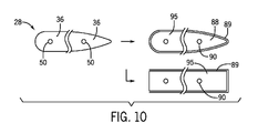
サイレンサバッフルは、前縁バッフル部と、後縁バッフル部と、前縁バッフル部と後縁バッフル部との間に配置された中間部と、を含む。サイレンサバッフルの外周部は、前縁バッフル部から後縁部まで徐々に湾曲し(例えば、テーパが付けられ)、より空力的な形状(例えば、翼形形状のバッフル)を形成する。いくつかの実施形態では、サイレンサバッフルの外周部は、鈍い後縁および/または前縁を含むことができる。バッフル部は、バッフル部の外面上にパターンを有してもよい。パターンは、凹部および/または突起(例えば、ディンプル)を含むことができ、バッフルシェル内に配置された音響材料(例えば、吸音材料)によってノイズが吸収されることを可能にする。 The silencer baffle includes a leading edge baffle portion, a trailing edge baffle portion, and an intermediate portion arranged between the leading edge baffle portion and the trailing edge baffle portion. The outer periphery of the silencer baffle is gradually curved (eg, tapered) from the leading edge baffle to the trailing edge to form a more aerodynamic shape (eg, airfoil-shaped baffle). In some embodiments, the outer periphery of the silencer baffle can include a blunt trailing edge and / or leading edge. The baffle portion may have a pattern on the outer surface of the baffle portion. The pattern can include recesses and / or protrusions (eg, dimples), allowing noise to be absorbed by an acoustic material (eg, sound absorbing material) placed within the baffle shell.
ここで図面を参照すると、図1は、本明細書に開示するモジュール化されたサイレンサバッフル部36を使用する吸気ダクト(例えば、空気ダクト27)を有する吸気ハウジング26内に配置された複数のバッフル部36を含むサイレンサバッフル28を有する発電システム10の一実施形態の概略図である。以下の説明では、軸方向もしくは軸方向軸13、半径方向もしくは半径方向軸15、および/または円周方向もしくは円周方向軸17を含む様々な方向を参照することができる。発電システム10は、圧縮された酸化剤(例えば、空気24)と燃料18との混合気を受け取り、燃焼させるための圧縮機14および1つもしくは複数の燃焼器16を有するガスタービンエンジン12と、空気燃料混合気の燃焼によって生成される高温ガスによって駆動される1つまたは複数のタービン20と、を含む。
Referring here to the drawings, FIG. 1 shows a plurality of baffles disposed within an
高温燃焼ガスはタービン20を駆動し、タービン20は次に圧縮機14および1つもしくは複数の他の負荷22を駆動する。例えば、図示する実施形態では、ガスタービンエンジン12は、発電機などの様々な負荷22に結合されてもよい。残りの高温ガスは、排気スタック30を通って排出され、大気に排出される。ガスタービンエンジン12は、吸気ガス24(例えば、周囲空気などの酸化剤)を吸気ハウジング26および空気ダクト27を通して空気圧縮機14に吸入する。図示する実施形態は空気24を示しているが、吸気ガス24は、空気、酸素、酸素富化空気、酸素還元空気、排気再循環ガス(EGR)、またはこれらの任意の組み合わせを含むことができる。それにもかかわらず、以下の議論では、非限定的な例として空気を参照する。吸気24が発電設備10に入ると、吸気24は、まずガスタービンエンジン12に結合された吸気ハウジング26を(例えば、軸方向13に)通過する。吸気ハウジング26は、吸気流路の周りに延在する側壁を含み、側壁は、対向する側壁部分またはパネル、例えば、上部パネル82および底部パネル84を含む。サイレンサバッフル28は、以下に詳細に説明するように、上部パネル82および底部パネル84に固定される。吸気ハウジング26の内部には、以下に詳細に説明するように、サイレンサバッフル28のアレイが利用される。サイレンサバッフル28はまた、通気システム32またはガスタービンエンジン12の他の領域で利用することもでき、これらは、ガスの温度が、非金属材料(例えば、プラスチック、複合材料など)で作られたサイレンサバッフル28を利用するのに十分低い。他の実施形態では、サイレンサバッフル28は、金属材料、または金属/非金属複合材料で作ることができる。一例では、通気システム32は、サイレンサバッフル28を使用できるように、通気システム32を通って排気されるガスの温度を低下させるためのファン34を含むことができる。
The hot combustion gas drives the
図2は、図1の複数のバッフル部36の一実施形態の線2-2に沿った断面図であり、複数のサイレンサバッフル28内のバッフル部のアライメントを示す。各サイレンサバッフル28(例えば、バッフル部36のロウ)は、互いに整列して相互にインターロックされた4つのバッフル部36を示している。サイレンサバッフル28の各々は、各ロウ38に任意の数のバッフル部36を含むことができる。例えば、サイレンサバッフル28は、2、3、4、5、6、7、8またはそれ以上のバッフル部36を含むことができる。サイレンサバッフル28のアレイは、モジュール(例えば、バッフル部36)に構成された複数のロウ38および複数のカラム40(図6を参照)を含む。図示する実施形態では、等しい数のロウ38およびカラム40が各サイレンサバッフル28内で利用されている。しかしながら、いくつかの実施形態では、各サイレンサバッフル28は、カラム40より多くのロウ38を含んでもよく、またはその逆であってもよいことが理解されよう。以下の説明では、カラム40は、パネル41(例えば、垂直または半径方向に積み重ねられたセグメント)と呼ぶことができる。本明細書で開示する実施形態は、任意の数のパネル41を使用することができる。例えば、発電システム10に使用される2~50、5~30、または15~25のパネルがあってもよい。パネル41は、互いに実質的に平行に整列され、空間43によって分離されている。
FIG. 2 is a cross-sectional view taken along line 2-2 of one embodiment of the plurality of
バッフル部36は、嵌合インターロック構造42などの複数の固定可能な結合部を介して互いに結合されている。嵌合インターロック構造42は、嵌合接合構造(例えば、雄接合部分44および雌接合部分46)を含むことができる。雄接合部分44が雌接合部分46に配置され、接合の剛性を高めている。嵌合インターロック構造42は、レール接合部、ダブテール接合部48、突合せ接合部、溝アセンブリ内のタング、または任意の他の適切なロック構造を含むことができる。例えば、接合部分44、46は、雄および雌部分、ダブテール接合部分、ラッチ部分、フックおよびスロット部分、あるいはこれらの任意の組み合わせを含むことができる。図示する実施形態では、接合部分44、46は、互いにインターロックする広がる雄接合部分44および広がる雌接合部分46(例えば、広がる表面)を含むことができる。接合部分44、46は、半径方向15に互いに摺動可能に結合することができ、したがって、嵌合レール部分として説明することができる。バッフル部36は、互いに隣接して整列している。図示する実施形態では、バッフル部36は、軸方向13および半径方向15に直線状に配置され、格子状の構成またはマトリックスを形成する。
The
各バッフル部36は、支持ロッド52(図6を参照)を受け入れるためのロッド支持通路50(例えば、ロッドレセプタクル)を含む。ロッド支持通路50は、円形、長方形、正方形、または支持ロッド52を受け入れるための任意の他の適切な形状であってもよい。支持ロッド52は、図11を参照してさらに説明するように、バッフル部36のカラム40を共に固定する。各パネル41は、様々な数の支持ロッド52を有することができる。例えば、パネル41は、2、3、4、5、6、7、8またはそれ以上の支持ロッド52を有することができる。いくつかの実施形態では、ロッド支持通路50のすべてが使用されるわけではない。例えば、パネル41は、1つおきのロッド支持通路50、2つのロッド支持通路50ごとなどに配置されたロッド52を有してもよい。
Each
サイレンサバッフル28は、前縁55を有する前縁バッフル部54と、後縁57を有する後縁部56と、各ロウ38の前縁バッフル部54と後縁バッフル部56との間に配置された1つまたは複数の中間バッフル部58と、を含む。吸気24は、吸気ハウジング26の第1の側面60から第2の側面62に流れる。吸気24が吸気ハウジング26を通って流れるにつれて、空気流はサイレンサバッフル28のより空気力学的な形状によって改善される。バッフル部36は、サイレンサバッフルの前縁部54と後縁部56との間に輪郭付けされた外面64を含むことができ、それによってサイレンサバッフル28の翼形形状の外周部66を形成する。例えば、前縁部54は、後縁部56および中間部58よりも幅が広くてもよい。バッフル部36は、図3~4を参照してさらに説明するように、バッフル部36の外面70上に配置された様々なパターン68を含むことができる。パターン68はまた、吸気24が吹き抜ける凹部または開口部を提供することができる。
The
図3は、サイレンサバッフル28の1つまたは複数のバッフル部36(例えば、前縁バッフル部54)の外面70の一実施形態の拡大斜視図である。前縁バッフル部54の外面70上に配置されたパターン68は、複数の凹部または開口部72を含む。開口部72は、1つまたは複数のバッフル部36の外面70の約20~60%、25~50%、30~40%、およびそれらの間のすべての百分率を覆うことができる。開口部72は、吸気24を開口部に露出させることを可能にし、1つまたは複数のバッフル部36の内部76(図5を参照)内に配置された音響材料74(例えば吸音材料)によってノイズが吸収されることを可能にする。開口部72は、前縁バッフル部54、後縁バッフル部56、および/または中間バッフル部58などの、バッフル部36のいずれかまたはすべてに配置されてもよい。図示する実施形態では、開口部72は、1つまたは複数の丸いまたは面取りされた縁部78を有する実質的に正方形または長方形の形状を有することができる。他の実施形態では、開口部72は、卵形、円形、三角形、六角形、またはこれらの組み合わせを含む他の形状を有してもよい。隣接する開口部72は、空間またはリブ79であってもよく、それは外面70および/または開口部72と同一平面上または突出していてもよい。特定の実施形態では、開口部72の幅のリブ79に対する比は、約10:1~1:1、8:1~2:1、または3:1~1.5:1、またはこれらの間の任意の比とすることができる。
FIG. 3 is an enlarged perspective view of an embodiment of the
図4は、サイレンサバッフル28の1つまたは複数のバッフル部36の外面70の一実施形態の拡大斜視図である。外面70は、後縁バッフル部56に沿ったような外面に対する吸気口24の乱流を増加させ、および/または流れの剥離を低減するように構成された1つまたは複数のパターン68を含むことができる。図示する実施形態では、パターン68はディンプルパターン74を含む。特定の実施形態では、ディンプルパターン74は、少なくとも後縁部56の周りに空気の乱流を生成し、それによって後縁部56付近の流れの剥離を遅らせる。ディンプルパターン74は、ディンプルが乱流を生成するように、複数の多角形形状(例えば、六角形、八角形など)、円形形状、または任意の他の適切な形状を含むことができる。
FIG. 4 is an enlarged perspective view of an embodiment of the
図5は、吸音材料78が充填されたバッフルシェル76を有する複数のバッフル部36の単一バッフル部36の一実施形態の斜視図である。図示するように、バッフルシェル76は、外側シェル部分75、内側構造支持体77、および支持ロッド52を受け入れるためのロッド支持通路50(例えば支持体77に沿った)を含む。バッフルシェル76は、射出成形、トランスファ成形、または任意の他の適切なプロセスによって形成することができる。バッフルシェル76は、アクリロニトリルブタジエンスチレン、ポリプロピレン、ポリエチレン、PVC、CPVC、または他の適切な熱可塑性ポリマーなどのプラスチックを含む適切な材料で構成することができる。いくつかの実施形態では、バッフルシェル76は、複合材料(例えば、マトリックス材料全体に分散した補強材料)で形成することができる。吸音材料78は、ミネラルウッド、玄武岩ウール、ガラス繊維、メラミン発泡体、ポリウレタン発泡体、または他の適切な材料を含むことができる。上で説明したように、バッフル部36は、カラム40に配置され(例えば、半径方向15に次々に積み重ねられ)、嵌合インターロック構造42(例えば、雄接合部分44、雌接合部分46)を介してロウ38に共に結合される(例えば、軸方向13にインターロックされる)。吸音材料78は、適切な形状およびサイズに切断され、バッフルシェル76に挿入され、ノイズ減衰部品として機能することができる。他の実施形態では、吸音材料78をバッフルシェル76内に注入することができる。バッフルシェル76は、個別に形成され、ロッド52上を摺動して、一体型サイレンサバッフル28を形成することができる。吸音材料78は、ロッド52上にねじ込まれる(例えば、組み立てられる)前または後に、バッフルシェル76内に配置することができる。
FIG. 5 is a perspective view of an embodiment of a
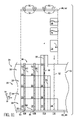
図6は、図2の複数のバッフル部36の一実施形態の線6-6に沿った断面図であり、複数のバッフル部36内に配置された複数のロッド52のアライメントを示す。破線85は、嵌合インターロック構造42が半径方向15に共に結合されている(例えば、共に摺動結合されている)場合の、雄接合部分44と雌接合部分46との重なり合いおよびインターロックを表す。ロッド52は、パネル80、82、84を拘束して、パネル80、82、84の負荷を低減するための荷重支持要素として機能することができる。上述したように、ロッド52は、円形、正方形、長方形、または任意の他の適切な形状であってもよい。図示する実施形態では、ロッド52の直径は約3.81センチメートル(1.5インチ)であるが、直径は変化してもよい。ロッド52の直径は、開口部またはロッド支持通路50に適合するように変化してもよい。上述したように、ロッド52は、ロッド支持通路50を通って配置され、カラム40(例えば、バッフル部36)を安定させる。ロッド52は、ロッド52の端部部分94によって吸気ハウジング26の隣接するパネル80(例えば、上部パネル82、底部パネル84)に結合する。ロッド52の各々は、複数のコネクタアセンブリ86を介して隣接するパネル80に固定される。コネクタアセンブリ86の様々な実施形態は、図9および図12~図14を参照してさらに理解することができる。
FIG. 6 is a cross-sectional view taken along line 6-6 of the embodiment of the plurality of
図7~図8は、線7-7に沿った図1のハウジング26および/またはダクト27のパネル80の壁部分の実施形態の断面図であり、パネル80に配置された複数の装着インターフェース88を示す。装着インターフェース88は、いくつかの実施形態では利用しなくてもよいことが理解されよう。装着インターフェース88は、ロッド52の一部分(例えば、端部部分94)を受け入れるための様々な開口部(例えば、レセプタクル)を含むことができる。装着インターフェース88は、平坦であってもよく(例えば、パネル80と同一平面上にある)、パネル80内に窪んでいてもよく、および/またはパネル80から外側に突出していてもよい。いくつかの実施形態では、装着インターフェース88は、パネル80内に外側境界またはリム89を含むことができ、あるいは装着インターフェース88の外周部を画定するようにパネル80から窪むか突出することができる。図7は、複数の装着レセプタクル90を介してロッド52の端部94を受け入れるように構成された複数の装着インターフェース88を含むパネル80の一実施形態の断面図であり、パネル80は、線7-7に沿った図1の吸気ハウジング26の上部82側または底部84側に配置されている。組み立て中に、バッフル部36の各カラム40は、パネル80のうちの1つ(例えば、底部パネル84)のレセプタクル90に配置された支持ロッド52に沿ってバッフル部36を半径方向に積み重ねることによって組み立てられる。続いて、バッフル部36の各追加のカラム40は、連続したバッフル部36を追加の支持ロッド52に沿って同時に摺動させるか、または摺動させることなく、隣接するカラム40の間の嵌合インターロック構造42に沿って、各連続したバッフル部分36を摺動させることによって組み立てられる。バッフル部の所望の数のカラム40がハウジング26内に組み立てられた後に、各ロッド52の端部部分94が反対側のパネル80(例えば、上部パネル82)の装着レセプタクル90に挿入される(図9を参照)。次いで、各ロッド52の端部部分94は、コネクタアセンブリ86を介して装着レセプタクル90内にロックされる。装着インターフェース88は、金属スタンピング、鋳造、機械加工、および/または別個の構造体をパネル80上に溶接することによって、両方のパネル80(例えば、上部パネル82、底部パネル84)内に予め製作することができる。
7-8 are cross-sectional views of an embodiment of the wall portion of the
図8は、複数の装着レセプタクル90を介してロッド52の端部94を受け入れるように構成された複数の装着インターフェース88を装着することを含むパネル80の一実施形態の断面図であり、装着インターフェース88は開放端部92を有し、パネル80は線7-7に沿った図1の吸気ハウジング26の上部82側または底部84側に沿って配置されている。図示する実施形態では、各装着インターフェース88は、開放端部から閉鎖端部93までの一定の幅91を有する外側境界またはリム89を有する。例えば、リム89は、サイレンサバッフル28の横方向19への移動を阻止するレールマウント構造を画定することができる。図示する実施形態では、装着インターフェース88は開放端部92を含み、バッフル部36(例えば、個々のバッフル部36、バッフル部36の予め組み立てられたロウ38および/またはカラム40)が、モジュラ方式(例えば、バッフル部36を積層することによって組み立てる)で1つずつ装着インターフェース88内に軸方向13に摺動することができる。次に、バッフル部36のカラム40(およびサイレンサバッフル28の各々の全体)は、図9により明確に示すように、1つまたは複数のロッド52を1つまたは複数のロッド支持通路50に挿入し、次に装着レセプタクル90に挿入することによってさらに安定させることができる。
FIG. 8 is a cross-sectional view of an embodiment of a
図9は、図6の線9-9内で得られた装着インターフェース88の一実施形態の拡大斜視図であり、リム89の各部分間の空間95にサイレンサバッフル28のバッフル部36が取り付けられていることを示す。例えば、図示する装着インターフェース88は、ハウジング26の対向するパネル80の一方または両方(例えば、上部パネル82および/または底部パネル84)に配置されてもよい。特定の実施形態では、装着インターフェース88は、同じパネルまたは異なるパネル82、84であってもよい。装着レセプタクル90は、ロッド52の端部部分94を受け入れる。いくつかの実施形態では、ロッド52は、対向するパネル80(例えば、パネル82、84)の一方または両方のコネクタアセンブリ86(図12~14を参照)によって定位置に固定(例えばロック)される。サイレンサバッフル28が交換される際には、バッフル部36のカラム40を取り外すために、ロッド52は端部部分94の近くで取り外される。コネクタアセンブリ86のうちのいくつかは、取り外し可能な結合となり、他の構成は半永久的な結合となる。取り外し可能な結合の場合には、ロッド52は、コネクタアセンブリ86を切り離すことによって取り外すことができる。半永久的接続の場合には、トーチまたは他の適切な装置を用いて溶接を切断することによってロッド52を取り外すことができる。特定の実施形態では、対向するパネル80のうちの少なくとも1つ(例えば、上部パネル82)は、アクセス開口部を通って上部取り付けおよび取り外しを可能にするように取り外し可能であってもよい。
FIG. 9 is an enlarged perspective view of an embodiment of the mounting
図10は、サイレンサバッフル28の一実施形態の拡大斜視図であり、サイレンサバッフル28は、装着インターフェース88内に(例えば、閉じた翼形形状のインターフェース内に半径方向に、または開口端部を有するレールインターフェース内に軸方向に)平行移動される。上述したように、サイレンサバッフル28は、任意の数のバッフル部36を含むことができる。サイレンサバッフル28は、カラム40を組み立てることによって組み立てることができる。各カラム40は、複数のバッフル部36を含む。バッフル部36は、ロッド支持通路50を通ってロッド52上にバッフル部36を1つずつ摺動させることによって、ロッド52に沿って組み立てられる。バッフル部36は、雄接合部分44および雌接合部分46によって結合される(例えば、共にスナップされ、共に嵌合する)。バッフル部36の所望の数のカラム40が形成された後に、ロッド52は、上述したように、装着インターフェース88の装着レセプタクル90に挿入される。
FIG. 10 is an enlarged perspective view of an embodiment of the
別の実施形態では、装着インターフェース88は開放端部92を含み、そのようにして、バッフル部36は、モジュール方式で1つずつまたはロウごとに装着インターフェース88内に軸方向に摺動することができる。言い換えれば、バッフル部36を、装着インターフェース88内に配置(例えば、整列)することができる。バッフル部36は、ロッド支持通路50が互いに実質的に整列するように位置合わせされる。バッフル部36は、雄接合部分44および雌接合部分46によって結合される(例えば、共にスナップされ、共に嵌合する)。ロッド支持通路50にロッド52を挿入することにより、バッフル部36のカラム40をさらに安定させることができる。ロッド52の端部部分94は、上述したように、装着レセプタクル90に固定することができる。
In another embodiment, the mounting
図11は、図1の部分的に組み立てられたサイレンサバッフル28の一実施形態を示す。バッフル部36は、ロッド52の各々の上に1つずつ半径方向15に積層されている。図示する実施形態では、カラム40a、40bは完全に組み立てられている。カラム40dは、ロッド52上の1つのバッフル部36のみで部分的に組み立てられている。破線85は、嵌合インターロック構造42(例えば、雄接合部分44および雌接合部分46)を介して隣接するバッフル部36の重なりを示す。嵌合インターロック構造42をロックすることにより、バッフル部36を、整列したカラム40およびロウ38内でさらに安定させる。嵌合インターロック構造42をロックすることは、雄接合部分44を雌接合部分46に挿入すること、接合部分44、46を互いにスナップすること、接合部分44、46を互いに嵌合すること、または任意の他の適切な結合方法を含むことができる。カラム40cは、バッフル部36の部分的に組み立てられたカラム40を示し、最終バッフル部36がカラム40cの上部に取り付けられている。図示するように、各ロッド52は底部パネル84に結合されている。上述したように、底部パネル84は、嵌合インターフェース88および嵌合レセプタクル90と共に予め製作されている。各ロッド52は、バッフル部36がロッド52上に摺動される前に、嵌合レセプタクル90に固定されてもよい。次いで、バッフル部36は、所望の数のバッフル部36がロッド52上に積み重ねられて各カラム40が完成するまで、ロッド支持通路50を介してロッド52上に摺動される。このプロセスは、バッフル部36の各カラム40について繰り返され、一方、バッフル部36の各隣接する一対のカラム40もまた、インターロック構造42によって互いに同時にインターロックすることができる。図示するように、インターロック構造42は、半径方向15にバッフル部36をロッド52上に下降させるのと同時に、半径方向15に互いに係合するように構成される。すべてのバッフル部36が組み立てられて所望の数のサイレンサバッフル28を画定した後に、対向するパネル80の間でサイレンサバッフル28を取り込むために、上部パネル80、82をサイレンサバッフル28の上に取り付けることができる。上部パネル80、82はまた、ロッド52を上部パネル80、82のレセプタクル90に挿入することによってロッド52を固定する。いくつかの実施形態では、バッフル部36を互いに隣接して配置することができ、ロッド52を整列したロッド支持通路50を通して摺動させることによって、ロッド52をバッフル部36内に摺動させることができる。他の実施形態では、サイレンサバッフル28は、図10を参照して上述したように、バッフル部36を軸方向に組み立てることによって組み立てることができる。この実施形態では、バッフル部36は、軸方向に完全に積層する(例えば、組み立てる)ことができる。次いで、ロッド52をロッド支持通路50に挿入することによって、ロッド52を隣接するバッフル部36に配置することができる。
FIG. 11 shows an embodiment of the partially assembled
図12~図14は、ロッド52の端部部分94を装着レセプタクル90に結合するために利用されるコネクタアセンブリ86の様々な実施形態を示す。コネクタアセンブリ86は、溶接、ろう付け、融着、またはこれらの組み合わせなどの半永久的結合であってもよい。コネクタアセンブリ86は、締結具(例えば、ねじ式レセプタクル、ボルト、ナットなど)、クランプ、またはこれらの任意の組み合わせなどの取り外し可能な結合であってもよい。コネクタアセンブリ86はまた、ロッド52が振動により時間の経過と共に偶然に緩むことを阻止するのに役立つ。
12-14 show various embodiments of the
図12は、コネクタアセンブリ86の一実施形態を示しており、コネクタアセンブリ86は、ロッド52を装着インターフェース88の装着レセプタクル90に結合する。図示する実施形態では、ロッド52は装着レセプタクル90に半径方向15に挿入され、サイレンサバッフル28はリム89内に配置される。装着インターフェース88は、パネル80(例えば、上部パネル82)の内壁96に結合される。パネル80の内壁96は、断熱体102の層によってパネル80の外壁98(例えば、上部パネル82)から熱的に隔離されている。断熱体102の層は、厚さが変化してもよい。断熱体102は、バッフルシェル76の内部で利用されるのと同じ断熱材料であってもよいし、異なる断熱材料であってもよい。装着インターフェース88は、取り外し可能な締結具(例えば、ねじ締結具、クランプ、雄/雌接合部など)または固定された接合部(例えば、溶接、ろう付け接合部など)を介してパネル80に取り外し可能にまたは固定的に結合されてもよい。
FIG. 12 shows an embodiment of the
図13は、コネクタアセンブリ86の別の実施形態を示し、コネクタアセンブリ86は、ロッド52を装着レセプタクル90に結合する。パネル80の内壁96は、断熱体102の層によって受け入れ構造の外壁98から分離されている。コネクタアセンブリ86は、有孔パネルまたはワッシャ104を含む。ワッシャ104は、装着インターフェース88内のロッド52およびバッフル部36に関連する荷重を支持することができる。ロッド52は、ワッシャ104に結合する少なくとも1つのスリーブ106によって収容される。スリーブ106は、装着インターフェース88内のロッド52の移動を低減する。図示する実施形態では、ロッド52の端部部分94、ワッシャ104、およびスリーブ106は、内壁96と外壁98との間のパネル80内に収容される(例えば、断熱体102内のパネル80内に窪んで)。ロッド52とサイレンサバッフル28(例えば、組み立てられたバッフル部36)が吸気ハウジング26から取り外される際には、ロッド52は端部部分94に隣接して切断され、ワッシャ104、端部部分94、およびスリーブ106は、装着インターフェース88の内壁96および外壁98の内側に残る。
FIG. 13 shows another embodiment of the
図14は、コネクタアセンブリ86の別の実施形態を示し、コネクタアセンブリ86は、ロッド52を装着レセプタクル90に結合する。パネル80の内壁96は、断熱体102の層によってパネル80の外壁98から分離されている。一対のボルト112などの取り外し可能な一対の締結具が、内壁96を通して挿入される。一対のボルト112は、装着レセプタクル90の一部を貫通して配置されてもよい。装着レセプタクル90は、内壁96の外側に配置され、ロッドガイド110を含むことができる。ロッドガイド110を使用して、ロッド52を装着レセプタクル90内に整列させることができる。図示する実施形態では、コネクタアセンブリ86は、ロッド52の荷重を支持するワッシャ104を含むことができる。
FIG. 14 shows another embodiment of the
図15は、本明細書に開示された実施形態によるバッフル部36を製造する方法150を示す。方法150は、嵌合インターロック機構42および1つもしくは複数のロッド支持通路50を有するバッフルシェル76を形成するステップ(ブロック152)を含む。上述したように、バッフルシェル76は、射出成形、トランスファ成形、または別の適切な方法によって製造することができる。方法150は、バッフルシェル76の内部をサイレンサ材料80で充填するステップ(ブロック154)を含む。いくつかの実施形態では、バッフルシェル76の内部にサイレンサ材料80を注入してもよいし、サイレンサ材料80を切断してバッフルシェル76に挿入してもよい。サイレンサ材料は、メラミン発泡体、ポリウレタン発泡体、または他の適切な発泡体材料などの様々な発泡体を含むことができる。方法150は、バッフルシェル76の外面70上にパターン68を形成するステップ(ブロック156)を含む。パターン68は、凹部、開口部72、突起部またはディンプル74、またはこれらの組み合わせを含むことができる。いくつかの実施形態では、いくつかのステップが単一のステップで実行されてもよいことが理解されよう。例えば、方法150は、バッフルシェル76を形成するステップ(ブロック152)を含み、嵌合インターロック機構42および1つもしくは複数のロッド支持通路50がバッフルシェル76の外面70上にパターン68を一度に形成する(ブロック156)ことができる。
FIG. 15 shows a
図16は、本明細書に開示された実施形態によるサイレンサバッフル28を取り付ける方法200を示す。方法200は、ロッド52に沿ってカラム40にサイレンサバッフル36を取り付けるステップ(ブロック202)を含む。方法200は、取り付け中に1つまたは複数のバッフル部36を検査、保守、修理、および/または交換するステップを含むことができる。サイレンサバッフル36はロッド支持通路50を含み、サイレンサバッフル36はロッド52上に半径方向15に摺動することができる。バッフル部36の隣接するカラム40は、雄接合部分44および雌接合部分46によって共に結合される(例えば、共にスナップされ、共に嵌合する)。方法200は、組み立てられたサイレンサバッフル28(例えば、サイレンサバッフル36を有するロッド52)を、吸気ハウジング26のパネル80(例えば、上部パネル82、底部パネル84)上に予め製作された装着レセプタクル90と位置合わせするステップ(ブロック204)を含む。方法200は、所望の数のロウ38およびカラム40に達するまで、サイレンサバッフル36を取り付け、組み立てられたサイレンサバッフル28を位置合わせするステップを繰り返すステップ(ブロック206)を含む。
FIG. 16 shows a
図17は、本明細書に開示された実施形態によるサイレンサバッフル28を取り外す方法250を示す。方法250は、取り外し中にバッフル部36の1つまたは複数を検査、保守、修理、および/または交換するステップを含むことができる。方法250は、ロッド52を端部部分94でパネル80から切り離すステップ(ブロック252)を含む。ロッド52を切り離すステップは、コネクタアセンブリ86を切り離すステップを含む。取り外し可能な結合について上述したように、各ロッド52は、コネクタアセンブリ86を切り離すことによって取り外すことができる。例えば、ロッド52は、ねじ締結具を外すこと、上部パネル80、82を取り外すこと、クランプを取り外すこと、またはこれらの任意の組み合わせによって取り外すことができる。半永久的接続の場合には、ロッド52は、トーチ、ブレード、または研磨工具を用いて溶接部を切断することによって取り外すことができる。方法250は、分解されるバッフルのロウの数に達するまで、ロッド52を切り離すステップを繰り返すステップ(ブロック254)を含む。方法250は、サイレンサバッフル28を吸気ハウジング(例えば、ダクト)のパネル80に固定するために、新たに組み立てられた(例えば、交換)ロッド52を装着レセプタクル90に取り付けるステップ(ブロック256)を含む。いくつかの実施形態では、交換ロッド52を取り付けるステップ(ブロック256)は、任意選択的に省略することができる。
FIG. 17 shows a
主題の技術的効果は、ガスタービンエンジン12の吸気導管内に複数のバッフル部36を組み立てることによってサイレンサバッフル28を形成することを含む。各サイレンサバッフル28は、前縁バッフル部54と、後縁バッフル部56と、前縁バッフル部54と後縁バッフル部56との間に配置された1つまたは複数の中間部58と、を含む。バッフル部36は、バッフル部36の外面上にパターン68を有することができる。パターン68(例えば、開口部)は、バッフルシェル76内に配置された音響材料74(例えば、吸音材料)によってノイズを吸収することができるように機能する。バッフル部36は、ロウ38およびカラム40に組み立てられてサイレンサバッフル28を形成する。各バッフル部36は、隣接するバッフル部36の対応する接合部分44、46に結合する雄接合部分44および/または雌接合部分46を含む。バッフル部の各々はまた、ロッド52を受け入れるように構成されたロッド支持通路50を含んでもよい。ロッド52は、雄接合部分44および雌接合部分46をさらに安定させる。バッフル部36を有するロッド52は、吸気ハウジング26または発電システム10の他の適切な場所に取り付けられる。本開示によれば、ロッド52の端部部分94は、装着レセプタクル90を介して装着インターフェース88に結合される。ロッド52は、コネクタアセンブリ86を介して装着レセプタクル90に結合される。バッフル部36を保守、修理、交換、アクセス、または検査する際には、ロッド52を交換してバッフル部36を保守または交換することができる。
The technical effect of the subject comprises forming the
本明細書は、特許請求する主題を開示するために実施例を用いており、最良の形態を含んでいる。また、いかなる当業者も本主題を実施することができるように実施例を用いており、任意のデバイスまたはシステムを製作し使用し、任意の組み込まれた方法を実行することを含んでいる。主題の特許可能な範囲は、特許請求の範囲によって定義され、当業者が想到するその他の実施例を含むことができる。このような他の実施例が請求項の字義通りの文言と異ならない構造要素を有する場合、または、それらが請求項の字義通りの文言と実質的な差異がない等価な構造要素を含む場合には、このような他の実施例は特許請求の範囲内であることを意図している。
[実施態様1]
流体流路を有する導管と、
前記流体流路に沿って前記流体導管内に配置されたサイレンサバッフル(28)と、を含み、前記サイレンサバッフル(28)は、嵌合インターロック構造(42)を介して互いに結合された複数のバッフル部(36)のうちの少なくとも2つを有する、システム。
[実施態様2]
前記導管に結合された機械を含む、実施態様1に記載のシステム。
[実施態様3]
前記機械はタービンエンジン(12)を含む、実施態様2に記載のシステム。
[実施態様4]
前記サイレンサバッフル(28)の前記複数のバッフル部(36)は、前縁部(54)と後縁部(56)とを含む、実施態様1に記載のシステム。
[実施態様5]
前記サイレンサバッフル(28)の前記複数のバッフル部(36)は、前記前縁部(54)と前記後縁部(56)との間に配置された1つまたは複数の中間部(58)を含む、実施態様4に記載のシステム。
[実施態様6]
前記サイレンサバッフル(28)の前記複数のバッフル部(36)は、前記サイレンサバッフル(28)の前縁(55)と後縁(57)との間の輪郭付けされた外面(64)を含む、実施態様1に記載のシステム。
[実施態様7]
前記輪郭付けされた外面(64)は、前記サイレンサバッフル(28)の翼形形状の外周部(66)を画定する、実施態様6に記載のシステム。
[実施態様8]
前記サイレンサバッフル(28)の前記複数のバッフル部(36)は、複数のロウ(38)および複数のカラム(40)を含む、実施態様1に記載のシステム。
[実施態様9]
前記嵌合インターロック構造(42)は、嵌合レール構造を含む、実施態様1に記載のシステム。
[実施態様10]
前記嵌合レール構造は、雌ダブテール接合部分内に配置された雄ダブテール接合部分を有するダブテール接合部(48)を含む、実施態様9に記載のシステム。
[実施態様11]
前記嵌合インターロック構造(42)の各々は、雌接合部分(46)に配置された雄接合部分(44)を含む、実施態様1に記載のシステム。
[実施態様12]
前記サイレンサバッフル(28)の前記複数のバッフル部(36)を貫通して延在する1つまたは複数の支持ロッド(52)を含む、実施態様1に記載のシステム。
[実施態様13]
前記1つまたは複数の支持ロッド(52)の各々は、前記サイレンサバッフル(28)の各部のカラム(40)を貫通して延在する、実施態様12に記載のシステム。
[実施態様14]
前記サイレンサバッフル(28)の前記複数のバッフル部(36)の各々は、シェル(76)内に配置された吸音材料(78)を含む、実施態様1に記載のシステム。
[実施態様15]
前記サイレンサバッフル(28)の前記複数のバッフル部(36)の各々は、支持ロッド(52)を受け入れるように構成されたロッド支持通路(50)を含む、実施態様14に記載のシステム。
[実施態様16]
前記サイレンサバッフル(28)は、凹部、開口部(72)、またはこれらの組み合わせのパターン(68)を有する外面(70)を有する、実施態様1に記載のシステム。
[実施態様17]
前記パターン(68)は、六角形、八角形、円形、またはこれらの任意の組み合わせを含む、実施態様16に記載のシステム。
[実施態様18]
前記流体流路に沿って前記流体導管内に配置された複数のサイレンサバッフル(28)を含み、前記複数のサイレンサバッフル(28)の各々は、前記嵌合インターロック構造(42)を介して互いに結合された前記複数のバッフル部(36)を有する、実施態様1に記載のシステム。
[実施態様19]
流体流路に沿って流体導管に装着するように構成されたサイレンサバッフル(28)の第1のバッフル部(36)を含み、前記第1のバッフル部(36)は、嵌合インターロック構造(42)を介して前記サイレンサバッフル(28)の第2のバッフル部(36)と互いに結合されるように構成される、システム。
[実施態様20]
流体流路に沿って流体導管内に装着するように構成されたサイレンサバッフル(28)の第1のバッフル部(36)であって、前記サイレンサバッフル(28)の第2のバッフル部(36)と互いに結合されるように構成された第1のバッフル部(36)と、
前記第1のバッフル部(36)内の第1の支持ロッド通路(50)と前記第2のバッフル部(36)内の第2の支持ロッド通路(50)とを貫通して延在するように構成された支持ロッド(52)と、を含むシステム。
This specification uses examples to disclose the subject matter claimed, and includes the best form. Also, any person skilled in the art will use the examples to enable this subject to be practiced, including making and using any device or system and performing any embedded method. The patentable scope of the subject matter is defined by the claims and may include other embodiments conceived by one of ordinary skill in the art. If such other embodiments have structural elements that do not differ from the literal wording of the claim, or if they contain equivalent structural elements that are not substantially different from the literal wording of the claim. Is intended that such other embodiments are within the scope of the claims.
[Embodiment 1]
A conduit with a fluid flow path and
A plurality of silencer baffles (28) disposed in the fluid conduit along the fluid flow path and the silencer baffles (28) coupled to each other via a mating interlock structure (42). A system having at least two of the baffle portions (36).
[Embodiment 2]
The system according to embodiment 1, comprising a machine coupled to the conduit.
[Embodiment 3]
The system according to
[Embodiment 4]
The system according to embodiment 1, wherein the plurality of baffle portions (36) of the silencer baffle (28) include a leading edge portion (54) and a trailing edge portion (56).
[Embodiment 5]
The plurality of baffle portions (36) of the silencer baffle (28) may have one or more intermediate portions (58) arranged between the leading edge portion (54) and the trailing edge portion (56). The system according to embodiment 4, comprising.
[Embodiment 6]
The plurality of baffle portions (36) of the silencer baffle (28) include a contoured outer surface (64) between the leading edge (55) and the trailing edge (57) of the silencer baffle (28). The system according to embodiment 1.
[Embodiment 7]
The system according to embodiment 6, wherein the contoured outer surface (64) defines an outer peripheral portion (66) of the airfoil shape of the silencer baffle (28).
[Embodiment 8]
The system according to embodiment 1, wherein the plurality of baffle portions (36) of the silencer baffle (28) include a plurality of rows (38) and a plurality of columns (40).
[Embodiment 9]
The system according to embodiment 1, wherein the fitting interlock structure (42) includes a fitting rail structure.
[Embodiment 10]
9. The system of
[Embodiment 11]
The system according to embodiment 1, wherein each of the mating interlock structures (42) comprises a male junction portion (44) disposed in a female junction portion (46).
[Embodiment 12]
The system according to embodiment 1, comprising one or more support rods (52) extending through the plurality of baffle portions (36) of the silencer baffle (28).
[Embodiment 13]
12. The system of
[Embodiment 14]
The system of embodiment 1, wherein each of the plurality of baffle portions (36) of the silencer baffle (28) comprises a sound absorbing material (78) disposed within a shell (76).
[Embodiment 15]
13. The system of
[Embodiment 16]
The system according to embodiment 1, wherein the silencer baffle (28) has an outer surface (70) having a recess, an opening (72), or a pattern (68) of a combination thereof.
[Embodiment 17]
16. The system of
[Embodiment 18]
A plurality of silencer baffles (28) arranged in the fluid conduit along the fluid flow path are included, and each of the plurality of silencer baffles (28) is connected to each other via the mating interlock structure (42). The system according to embodiment 1, wherein the plurality of baffle portions (36) are coupled.
[Embodiment 19]
A first baffle portion (36) of a silencer baffle (28) configured to be mounted in a fluid conduit along a fluid flow path is included, wherein the first baffle portion (36) has a mating interlock structure ( A system configured to be coupled to a second baffle portion (36) of the silencer baffle (28) via 42).
[Embodiment 20]
A first baffle portion (36) of a silencer baffle (28) configured to be mounted in a fluid conduit along a fluid flow path, the second baffle portion (36) of the silencer baffle (28). A first baffle portion (36) configured to be coupled to each other, and
It extends through the first support rod passage (50) in the first baffle portion (36) and the second support rod passage (50) in the second baffle portion (36). A system including a support rod (52) configured in.
10 発電システム、発電設備
12 ガスタービンエンジン
13 軸方向、軸方向軸
14 圧縮機
15 半径方向、半径方向軸
16 燃焼器
17 円周方向軸
18 燃料
19 横方向
20 タービン
22 負荷
24 吸気、吸気口、吸気ガス、空気
26 吸気ハウジング
27 空気ダクト
28 サイレンサバッフル
30 排気スタック
32 通気システム
34 ファン
36 バッフル部、サイレンサバッフル
38 ロウ
40 カラム
41 パネル
42 嵌合インターロック構造、嵌合インターロック機構
43 空間
44 雄接合部分
46 雌接合部分
48 ダブテール接合部
50 ロッド支持通路
52 支持ロッド、交換ロッド
54 前縁部、前縁バッフル部
55 前縁
56 後縁部、後縁バッフル部
57 後縁
58 中間部、中間バッフル部
60 第1の側面
62 第2の側面
64 輪郭付けされた外面
66 翼形形状の外周部
68 パターン
70 外面
72 開口部
74 ディンプルパターン、音響材料
75 外側シェル部分
76 バッフルシェル、バッフル部の内部
77 内側構造支持体
78 吸音材料、縁部
79 リブ
80 パネル、サイレンサ材料
82 上部パネル
84 底部パネル
85 破線
86 コネクタアセンブリ
88 装着インターフェース、嵌合インターフェース
89 リム
90 装着レセプタクル、嵌合レセプタクル
91 一定の幅
92 開放端部
93 閉鎖端部
94 端部部分
95 空間
96 内壁
98 外壁
102 断熱体
104 ワッシャ
106 スリーブ
110 ロッドガイド
112 ボルト
150 方法
152 ブロック
154 ブロック
156 ブロック
200 方法
202 ブロック
206 ブロック
250 方法
252 ブロック
254 ブロック
256 ブロック
10 Power generation system, power generation equipment 12 Gas turbine engine 13 Axial, Axial axis 14 Compressor 15 Radial, radial axis 16 Combustor 17 Circumferential axis 18 Fuel 19 Lateral 20 Turbine 22 Load 24 Intake, intake port, Intake gas, air 26 Intake housing 27 Air duct 28 Silencer baffle 30 Exhaust stack 32 Ventilation system 34 Fan 36 Baffle part, Silencer baffle 38 Row 40 Column 41 Panel 42 Fitting interlock structure, Fitting interlock mechanism 43 Space 44 Male joint Part 46 Female joint 48 Dovetail joint 50 Rod support passage 52 Support rod, replacement rod 54 Front edge, front edge baffle 55 Front edge 56 Trailing edge, trailing edge baffle 57 Trailing edge 58 Middle, middle baffle 60 First side surface 62 Second side surface 64 Outlined outer surface 66 Wing-shaped outer circumference 68 Pattern 70 Outer surface 72 Opening 74 Dimple pattern, acoustic material 75 Outer shell part 76 Baffle shell, Baffle part inner 77 Inner Structural support 78 Sound absorbing material, edge 79 rib 80 panel, silencer material 82 top panel 84 bottom panel 85 broken line 86 connector assembly 88 mounting interface, mating interface 89 rim 90 mounting receptacle, mating receptacle 91 constant width 92 open end Part 93 Closed end 94 End part 95 Space 96 Inner wall 98 Outer wall 102 Insulation 104 Washer 106 Sleeve 110 Rod guide 112 Bolt 150 Method 152 Block 154 Block 156 Block 200 Method 202 Block 206 Block 250 Method 252 Block 254 Block 256 Block
Claims (12)
前記流体流路に沿って前記導管内に配置されたサイレンサバッフル(28)と
を備えるシステムであって、前記サイレンサバッフル(28)が複数のバッフル部(36)を有していて、前記複数のバッフル部(36)のうちの少なくとも2つが嵌合インターロック構造(42)を介して互いに結合されており、
前記嵌合インターロック構造(42)が嵌合レール構造を含み、
前記嵌合レール構造が、雌ダブテール接合部分内に配置された雄ダブテール接合部分を有するダブテール接合部(48)を含む、システム。 A conduit with a fluid flow path and
A system including a silencer baffle (28) arranged in the conduit along the fluid flow path, wherein the silencer baffle (28) has a plurality of baffle portions (36). At least two of the baffle portions (36) of the above are coupled to each other via a mating interlock structure (42).
The mating interlock structure (42) includes a mating rail structure.
A system in which the fitting rail structure comprises a dovetail joint (48) having a male dovetail joint disposed within a female dovetail joint.
Applications Claiming Priority (2)
| Application Number | Priority Date | Filing Date | Title |
|---|---|---|---|
| US15/267,001 US10119469B2 (en) | 2016-09-15 | 2016-09-15 | Method and apparatus for modularized inlet silencer baffles |
| US15/267,001 | 2016-09-15 |
Publications (2)
| Publication Number | Publication Date |
|---|---|
| JP2018044547A JP2018044547A (en) | 2018-03-22 |
| JP7071029B2 true JP7071029B2 (en) | 2022-05-18 |
Family
ID=59846403
Family Applications (1)
| Application Number | Title | Priority Date | Filing Date |
|---|---|---|---|
| JP2017169092A Active JP7071029B2 (en) | 2016-09-15 | 2017-09-04 | Methods and equipment for modularized intake silencer baffles |
Country Status (4)
| Country | Link |
|---|---|
| US (1) | US10119469B2 (en) |
| EP (1) | EP3296547B1 (en) |
| JP (1) | JP7071029B2 (en) |
| CN (1) | CN107829829B (en) |
Families Citing this family (10)
| Publication number | Priority date | Publication date | Assignee | Title |
|---|---|---|---|---|
| US10722990B2 (en) | 2016-09-15 | 2020-07-28 | General Electric Company | Method for installing and removing modularized silencer baffles |
| CN108278157B (en) | 2017-01-06 | 2022-08-02 | 通用电气公司 | System and method for improved inlet silencer baffle |
| CN108278158B (en) * | 2017-01-06 | 2022-05-13 | 通用电气公司 | System and method for an improved inlet muffler baffle |
| US10508573B2 (en) * | 2017-04-11 | 2019-12-17 | Caterpillar Inc. | Baffle assembly for a duct |
| US10468010B2 (en) * | 2017-05-09 | 2019-11-05 | Quanta Computer Inc. | Acoustical attenuator in storage array to improve performance |
| GB2568055B (en) * | 2017-11-02 | 2023-02-01 | Brush Elec Machines | Air outlet sound absorber for a rotating electrical machine |
| US11536487B2 (en) * | 2018-08-29 | 2022-12-27 | Zheng Sheng Environmental Technology Co., Ltd. | Diffusion muffling device, diffusion resonance muffling device, full-frequency diffusion muffling device, muffling system for ventilation channel, and muffling method using the same |
| US11614010B2 (en) * | 2020-09-01 | 2023-03-28 | Caterpillar Inc. | Panel assembly and aftertreatment assembly including panel assemblies |
| US11815018B2 (en) | 2021-12-15 | 2023-11-14 | General Electric Company | Box-shaped air intake silencer with vertical baffles for gas turbine system |
| CN114756097B (en) * | 2022-03-31 | 2024-08-23 | 联想(北京)有限公司 | Sound absorbing device, processing method and electronic equipment |
Citations (1)
| Publication number | Priority date | Publication date | Assignee | Title |
|---|---|---|---|---|
| JP2014177921A (en) | 2013-03-15 | 2014-09-25 | Mitsubishi Heavy Ind Ltd | Silencer for gas turbine, and gas turbine including the same |
Family Cites Families (296)
| Publication number | Priority date | Publication date | Assignee | Title |
|---|---|---|---|---|
| US1953156A (en) | 1931-06-29 | 1934-04-03 | Independent Air Filter Company | Air filter |
| US2205730A (en) * | 1938-04-16 | 1940-06-25 | Arthur C Morgan | Building construction |
| US2299112A (en) * | 1939-10-30 | 1942-10-20 | Robert C Brown Jr | Acoustic filter |
| US2519161A (en) | 1946-07-18 | 1950-08-15 | Thomas T Tucker | Acoustic testing structure, including sound absorbing panels |
| GB682845A (en) | 1948-02-18 | 1952-11-19 | Electrolux Corp | Improvements in or relating to air filtering machines particularly for use as vacuumcleaners |
| GB724179A (en) | 1950-11-27 | 1955-02-16 | Electrolux Corp | Improvements in air filtering devices and suction cleaners |
| GB759992A (en) | 1954-01-20 | 1956-10-24 | Victoria Werke Ag | Frames for motor-cycles |
| US2792906A (en) | 1954-09-13 | 1957-05-21 | Evans Reid | Support for air filter units and the like |
| US2916101A (en) | 1957-02-25 | 1959-12-08 | Israel A Naman | Sound-absorbing structures |
| US3093401A (en) | 1960-12-19 | 1963-06-11 | American Air Filter Co | Unit air filter latch |
| GB1045309A (en) | 1962-12-04 | 1966-10-12 | Fram Corp | Filter cartridges |
| GB1072791A (en) | 1964-06-11 | 1967-06-21 | Ass Elect Ind | Improvements relating to air filter units |
| GB1082503A (en) | 1965-08-19 | 1967-09-06 | Tmm Research Ltd | Improvements relating to air filtering arrangements for a waste removal system on textile combing machines |
| GB1104643A (en) | 1966-03-23 | 1968-02-28 | Fram Filters Ltd | Improvements in or relating to air filters |
| US3360910A (en) | 1966-05-31 | 1968-01-02 | Envirco Inc | Filter framing system |
| US3423908A (en) | 1966-06-16 | 1969-01-28 | Cambridge Filter Corp | Side-loading filter housing |
| US3345805A (en) | 1966-09-01 | 1967-10-10 | Microtron Corp | Apparatus for cleaning filters |
| CH447788A (en) | 1967-01-13 | 1967-11-30 | American Air Filter Co | Gas filter holder |
| US3487768A (en) | 1968-03-20 | 1970-01-06 | American Air Filter Co | Damper fastening arrangement |
| US3552704A (en) | 1968-10-14 | 1971-01-05 | American Air Filter Co | Clamping device for simultaneously securing two panels to a support |
| US3576096A (en) | 1969-06-19 | 1971-04-27 | American Air Filter Co | Filter frame latching assembly |
| US3747305A (en) | 1971-04-16 | 1973-07-24 | American Air Filter Co | Tubular gas filter apparatus |
| US3750374A (en) | 1971-06-07 | 1973-08-07 | Delbag Luftfilter Gmbh | Gas filters |
| US3698509A (en) | 1971-06-24 | 1972-10-17 | United Aircraft Corp | Inlet noise silencer for a jet engine |
| US3740934A (en) | 1971-07-30 | 1973-06-26 | American Air Filter Co | Air filtering unit including a clamping assembly |
| US3774946A (en) | 1971-09-30 | 1973-11-27 | American Air Filter Co | Door or panel latch assembly |
| US3783768A (en) * | 1971-10-14 | 1974-01-08 | Imp Damper Co Inc | Damper assembly |
| US3733793A (en) | 1971-10-22 | 1973-05-22 | American Air Filter Co | Filter latch |
| US3759017A (en) | 1971-10-22 | 1973-09-18 | American Air Filter Co | Latch for a filter apparatus |
| IT984319B (en) | 1972-05-08 | 1974-11-20 | Hatz Motoren | INTERNAL COMBUSTION MACHINE WITH SOUNDPROOFING |
| US3926155A (en) | 1972-05-08 | 1975-12-16 | Hatz Motoren | Internal combustion engine with silencing means |
| GB1407125A (en) | 1973-02-22 | 1975-09-24 | Gen Motors Ltd | Pressure responsive visual warning devices |
| US3993464A (en) | 1973-04-13 | 1976-11-23 | Anf Frangeco S.A. | Air filter |
| US3860273A (en) | 1973-05-07 | 1975-01-14 | Eagle Picher Ind Inc | Clamp for air filter hose |
| US3949356A (en) | 1973-05-14 | 1976-04-06 | Caterpillar Tractor Co. | Vehicle systems monitor discriminating between emergency conditions and deferrable maintenance needs |
| US3837149A (en) | 1973-06-27 | 1974-09-24 | Deere & Co | Engine enclosure and cooling system with rotary filter |
| US3966163A (en) | 1974-05-28 | 1976-06-29 | American Air Filter Company, Inc. | Filter retaining latch |
| US4050913A (en) * | 1974-06-28 | 1977-09-27 | Pall Corporation | Vortex air cleaner assembly with acoustic attenuator |
| US3891253A (en) | 1974-09-26 | 1975-06-24 | American Air Filter Co | Door handle and latch device |
| US4068736A (en) * | 1975-04-14 | 1978-01-17 | Tempmaster Corporation | Method and device for reducing noise |
| US3999969A (en) | 1975-07-21 | 1976-12-28 | American Air Filter Company, Inc. | Air filtering unit |
| DE2545309C2 (en) | 1975-10-07 | 1984-09-20 | Delbag-Luftfilter Gmbh, 1000 Berlin | Process for inserting and replacing suspended matter filter elements for nuclear systems and installation frames for carrying out the process |
| US4061373A (en) | 1976-05-05 | 1977-12-06 | American Air Filter Company, Inc. | Door latch device |
| US4178159A (en) | 1977-09-21 | 1979-12-11 | Fecteau Ronald D | Clean room filter assembly |
| US4171211A (en) | 1978-04-13 | 1979-10-16 | American Air Filter Company, Inc. | Air filtering unit |
| US4217122A (en) | 1978-11-01 | 1980-08-12 | American Air Filter Company, Inc. | Filter retaining latch |
| US4224765A (en) | 1979-02-07 | 1980-09-30 | Song John S | Plant culture container |
| US4276069A (en) | 1979-09-12 | 1981-06-30 | American Air Filter Company, Inc. | Filter arrangement |
| US4316522A (en) * | 1979-11-07 | 1982-02-23 | Industrial Acoustics Company, Inc. | Acoustic filter silencer |
| US4253856A (en) | 1979-11-09 | 1981-03-03 | American Air Filter Company, Inc. | Filter arrangement |
| US4266956A (en) | 1979-12-26 | 1981-05-12 | American Air Filter Company, Inc. | Filter clamping device |
| JPS5825488B2 (en) | 1980-06-16 | 1983-05-27 | 株式会社日立製作所 | Manufacturing method of air filter for air conditioner |
| JPS5731738A (en) | 1980-08-01 | 1982-02-20 | Hitachi Ltd | Indoor unit of air conditioner |
| US4323379A (en) | 1980-11-28 | 1982-04-06 | Facet Enterprises, Inc. | Air filter panel |
| US4648311A (en) | 1980-12-08 | 1987-03-10 | Deutz-Allis Corporation | Downwardly swinging replaceable air filter for a vehicle cab |
| DE3119190A1 (en) | 1981-05-14 | 1982-12-16 | Klöckner-Humboldt-Deutz AG, 5000 Köln | INTAKE SYSTEM WITH SWINGARM TUBES |
| DE8214792U1 (en) | 1982-05-18 | 1982-08-26 | Delbag-Luftfilter Gmbh, 1000 Berlin | SUPPORT AND RECEIVER FRAME FOR AIR FILTER ELEMENTS |
| JPS59153944A (en) | 1983-02-21 | 1984-09-01 | Aisin Seiki Co Ltd | Dash pot |
| US4498914A (en) | 1983-03-03 | 1985-02-12 | Donaldson Company, Inc. | Filter apparatus including apparatus for clamping an air filter element in a filter housing |
| US4519823A (en) | 1983-03-16 | 1985-05-28 | United Air Filter Company | Air filter assembly having improved clamping means for filter media |
| US4488888A (en) | 1983-05-16 | 1984-12-18 | Conair Corporation | Table top air filter |
| US4521234A (en) | 1983-07-19 | 1985-06-04 | Flanders Filters,Inc. | Housing for high efficiency particulate air filters |
| JPS6060435A (en) | 1983-09-12 | 1985-04-08 | Hitachi Ltd | Air filter device |
| JPS6060433A (en) | 1983-09-12 | 1985-04-08 | Hitachi Ltd | Air filter device |
| DE3484463D1 (en) | 1983-12-16 | 1991-05-23 | Nitta Co | AIR CLEANER. |
| US4555255A (en) | 1984-05-23 | 1985-11-26 | Allis-Chalmers Corporation | Corner connector clip in an air filter grid |
| US4600419A (en) | 1984-11-29 | 1986-07-15 | Cambridge Filter Corporation | High efficiency, down flow air filter sealing and support system |
| DE3447901C2 (en) | 1984-12-28 | 1994-07-07 | Flaekt Ab | Modular frame arrangement that can be suspended from the ceiling of a room to hold filters with a fluid seal for clean room ceilings |
| JPS61240039A (en) | 1985-04-17 | 1986-10-25 | Hitachi Ltd | Ceiling-mounted air conditioner |
| US4632681A (en) | 1985-04-25 | 1986-12-30 | Wheelabrator Corporation Of Canada, Ltd. | Locking apparatus for filter elements |
| US4608066A (en) | 1985-07-31 | 1986-08-26 | Flanders Filters, Inc. | Clean room adapted for variable work area configurations |
| US4707168A (en) | 1985-08-21 | 1987-11-17 | Konan Electric Co., Ltd. | Case guard device for air filter and lubricator of compressed air system |
| DE3536376C1 (en) | 1985-10-11 | 1988-08-18 | Bayerische Motoren Werke AG, 8000 München | Detachable plug connection between components |
| FR2591507B1 (en) | 1985-12-17 | 1988-04-08 | Peugeot Aciers Et Outillage | AIR FILTER CARTRIDGE, ESPECIALLY FOR A MOTOR VEHICLE. |
| US4808203A (en) | 1986-01-17 | 1989-02-28 | Hubert Sabourin Inc. | Dust collector |
| HU207763B (en) | 1986-06-20 | 1993-05-28 | Attila Krisztics | Internal combustion engine |
| JPS639742A (en) | 1986-06-27 | 1988-01-16 | Honda Motor Co Ltd | Cylindrical shock absorber for vehicles |
| US4701196A (en) | 1986-09-15 | 1987-10-20 | Research Products Corporation | Air filter assembly |
| US4860420A (en) | 1987-04-07 | 1989-08-29 | Flanders Filters, Inc. | Method of fabricating a clean room filter bank |
| DE8715857U1 (en) | 1987-11-30 | 1988-08-04 | A. Kayser GmbH & Co KG, 3352 Einbeck | Hose |
| FI78337C (en) | 1988-02-03 | 1989-07-10 | Te Ilma Ab Oy | Valve for replacement air |
| US4946484A (en) | 1988-02-05 | 1990-08-07 | Donaldson Company, Inc. | Support for clean room ceiling grid system |
| US4944142A (en) | 1988-08-22 | 1990-07-31 | Honda Giken Kogyo Kabushiki Kaisha | Power lawnmower construction |
| JPH02140525A (en) | 1988-11-18 | 1990-05-30 | Sanyo Electric Co Ltd | Air filter fixing device |
| US4889543A (en) | 1988-12-08 | 1989-12-26 | Burt Jerry D | Air filtering system |
| US5109310A (en) | 1989-03-07 | 1992-04-28 | Alps Electric Co., Ltd. | Disk drive device with unified actuator assembly |
| JPH02252185A (en) | 1989-03-27 | 1990-10-09 | Mitsubishi Electric Corp | magnetic disk device |
| US5014608A (en) | 1989-04-27 | 1991-05-14 | Brod & Mcclung - Pace Co. | Clean room air system |
| US4976757A (en) | 1989-05-04 | 1990-12-11 | Comp-Aire Systems, Inc. | Filtration plenum module constructed for on-site assembly |
| US5062872A (en) | 1989-05-12 | 1991-11-05 | Pneumafil Corporation | Air filter with horizontal filter elements |
| DE3924293A1 (en) | 1989-07-22 | 1991-01-24 | Daimler Benz Ag | DEVICE FOR THE FRESH AIR SUPPLY TO THE VEHICLE'S ROOM |
| GB9817387D0 (en) | 1998-08-10 | 1998-10-07 | Diffusion Environmental System | Air conditioning |
| US4986050A (en) | 1989-08-22 | 1991-01-22 | Filtra Corporation | Modular support system for a filter-type ceiling grid |
| US5140819A (en) | 1989-09-28 | 1992-08-25 | Sundstrand Corporation | Turbine inlet silencer |
| WO1991005157A1 (en) | 1989-09-28 | 1991-04-18 | Sundstrand Corporation, Inc. | Turbine inlet silencer |
| DE3934433A1 (en) | 1989-10-14 | 1991-04-25 | Mann & Hummel Filter | AIR FILTER WITH RADIAL SEALING FILTER INSERT |
| US5003974A (en) | 1989-10-27 | 1991-04-02 | Mou Lin Her | First-aid gas mask |
| US4978375A (en) | 1989-12-29 | 1990-12-18 | Permanent Solution Industries, Inc. | Plastic air filter housing assembly for use in air conditioners and heating systems |
| JPH03207935A (en) | 1990-01-11 | 1991-09-11 | Sanyo Electric Co Ltd | Fitting device of air filter |
| US5088299A (en) | 1990-03-29 | 1992-02-18 | Mclean Midwest Corporation | Industrial liquid circulating and cooling machine |
| DE4013645A1 (en) | 1990-04-27 | 1991-05-08 | Vero Electronics Gmbh | Inserting air filter mat into electronic housing |
| US5394786A (en) | 1990-06-19 | 1995-03-07 | Suppression Systems Engineering Corp. | Acoustic/shock wave attenuating assembly |
| DE4024898A1 (en) | 1990-08-06 | 1992-02-13 | Mann & Hummel Filter | INTAKE AIR FILTER FOR THE COMBUSTION ENGINE OF A VEHICLE |
| DE4028899C1 (en) | 1990-09-12 | 1992-01-09 | Mercedes-Benz Aktiengesellschaft, 7000 Stuttgart, De | |
| US5454756A (en) | 1991-08-21 | 1995-10-03 | Pace Company | Clean room ventilation system |
| JP3043141B2 (en) | 1991-11-15 | 2000-05-22 | 三洋電機株式会社 | Air conditioner |
| JPH05141645A (en) | 1991-11-21 | 1993-06-08 | Miura Co Ltd | Square-shaped shell-and-tube-once through boiler |
| US5313759A (en) | 1991-12-18 | 1994-05-24 | Chase Iii Francis H | Cleanroom ceiling system |
| DE4203864C2 (en) | 1992-02-11 | 1993-12-02 | Deere & Co | Positioning device for air filters |
| US5291355A (en) | 1992-03-10 | 1994-03-01 | Nec Corporation | Micro miniature hard disk drive |
| DE4211303A1 (en) | 1992-04-06 | 1993-10-07 | Kroely Helmut Dental Lab | Paper filter for dust extractor for collecting precious metal dust - has parallel adjacent filter bags fastened to common support frame in suction opening of unit to cover its intake cross=section |
| JP3177336B2 (en) | 1992-08-24 | 2001-06-18 | 三洋電機株式会社 | Air filter for air conditioner |
| US5572847A (en) * | 1992-08-28 | 1996-11-12 | Jte, Inc. | Rapidly erectable, removable, reusable and raisable outdoor acoustical wall system |
| DE9212739U1 (en) | 1992-09-22 | 1992-11-12 | Filterwerk Mann & Hummel Gmbh, 7140 Ludwigsburg | Device for regulating the temperature of the intake air of internal combustion engines |
| JP3207935B2 (en) | 1992-10-23 | 2001-09-10 | 本田技研工業株式会社 | Anti-lock brake control device |
| US5331748A (en) | 1992-10-26 | 1994-07-26 | Miller Jr Kenneth C | Air filter for portable hair blow dryer |
| US5417610A (en) | 1992-11-06 | 1995-05-23 | Daw Technologies, Inc. | Method and device for reducing vortices at a cleanroom ceiling |
| US5279632A (en) | 1992-12-17 | 1994-01-18 | International Business Machines Corporation | Planar clean room ceiling structure |
| US5273564A (en) | 1992-12-24 | 1993-12-28 | Research Products Corporation | One piece filter media framework |
| US5295602A (en) | 1993-03-17 | 1994-03-22 | General Motors Corporation | Housing with snap latch closure |
| US5332409A (en) | 1993-03-29 | 1994-07-26 | A. J. Dralle, Inc. | Air filtration system |
| DE9305767U1 (en) | 1993-04-16 | 1993-06-17 | Filterwerk Mann & Hummel Gmbh, 7140 Ludwigsburg | Air filters for the interior of motor vehicles |
| JP3134621B2 (en) | 1993-06-08 | 2001-02-13 | ダイキン工業株式会社 | Filter mounting structure for air conditioner |
| US5286201A (en) | 1993-06-21 | 1994-02-15 | Yu Chih Ming | Air dryer device for a dental 3-way syringe |
| DE4323985A1 (en) | 1993-07-17 | 1995-01-19 | Knecht Filterwerke Gmbh | Fastening device for filter housings, in particular housings for air filters, on motor vehicles |
| CA2168126C (en) | 1993-08-17 | 2005-07-12 | Seyed A. Angadjivand | Method of charging electret filter media |
| DE4329522A1 (en) | 1993-09-02 | 1995-03-09 | Mann & Hummel Filter | Throttle device |
| US5401285A (en) | 1993-09-17 | 1995-03-28 | Donaldson Company, Inc. | Air cleaner having scavenger arrangement for precleaner and filter thereof |
| US5458772A (en) | 1994-01-13 | 1995-10-17 | Filtercorp Partners L.P. | Adjustable filter holder assembly |
| ATE195262T1 (en) | 1994-01-15 | 2000-08-15 | Filtrair Bv | FILTER ELEMENT FOR REMOVAL OF DUST PARTICLES FROM A GAS |
| DE4404105A1 (en) | 1994-02-09 | 1995-08-10 | Liu Ming Jen | Lighting fixture with air filtering and ventilating unit |
| DE4412474C2 (en) | 1994-04-14 | 1997-08-07 | Mann & Hummel Filter | Air filter, in particular for the intake air of an internal combustion engine |
| US5417205A (en) | 1994-06-07 | 1995-05-23 | Wang; Jen-Yi | Air filter for the nose |
| US5512086A (en) | 1994-06-14 | 1996-04-30 | Appliance Development Corporation | High-efficiency air filtering apparatus |
| US5532439A (en) | 1994-06-23 | 1996-07-02 | Transco Products Inc. | Silencer assembly with acoustical modules therein |
| JP3131540B2 (en) | 1994-08-04 | 2001-02-05 | 日本碍子株式会社 | Support structure of filter element in dust collector |
| DE4431450A1 (en) | 1994-09-03 | 1996-03-07 | Petronella Von Abeelen | Air filter |
| US5512074A (en) | 1994-09-19 | 1996-04-30 | Farr Company | Air filter assembly |
| DE4438007A1 (en) | 1994-10-25 | 1996-05-02 | Karl Wilhelm Ludwig Quaschner | Compressed air filter with upper and lower fastening |
| US5514197A (en) | 1995-02-07 | 1996-05-07 | Tekstarter Co., Ltd. | Air filter device for an air-conditioning apparatus |
| JP3583827B2 (en) | 1995-02-20 | 2004-11-04 | 日本無機株式会社 | Device for connecting orthogonal rod-shaped members in an assembly frame for mounting an air filter |
| JP2761510B2 (en) | 1995-02-21 | 1998-06-04 | 北村バルブ製造株式会社 | Air filter mounting device for valve actuator |
| US5637124A (en) | 1995-03-23 | 1997-06-10 | Helical Dynamics, Inc. | Modular air cleaning system |
| DE19511911A1 (en) | 1995-03-31 | 1996-10-02 | Mann & Hummel Filter | Oil bath air filter |
| JP3343309B2 (en) * | 1995-04-05 | 2002-11-11 | ダブリュ.コッター ロッドマン | Acoustic panel system |
| US5602700A (en) | 1995-04-12 | 1997-02-11 | Quantum Corporation | Aerodynamic actuator-filter latch for hard disk drive |
| RO117217B1 (en) | 1995-05-26 | 2001-11-30 | Ioan Darjoanca | Multifunctional ecological lustre |
| DE19526934A1 (en) | 1995-07-24 | 1997-01-30 | Mann & Hummel Filter | Fastener |
| JP3621765B2 (en) | 1995-09-19 | 2005-02-16 | 日本無機株式会社 | Air filter mounting device |
| US5733348A (en) | 1995-10-27 | 1998-03-31 | Skarsten; Darrell L. | Air filtering apparatus |
| JPH09155158A (en) | 1995-12-11 | 1997-06-17 | Opt D D Melco Lab:Kk | Electrochemical equipment |
| JPH09184656A (en) | 1995-12-28 | 1997-07-15 | Mitsubishi Heavy Ind Ltd | Ceiling mounted type air conditioner |
| JPH09173892A (en) | 1995-12-28 | 1997-07-08 | Tenetsukusu:Kk | Dielectric type air filter |
| US5984991A (en) | 1996-01-25 | 1999-11-16 | Appliance Development Corp. | High-efficiency air filter |
| JPH09287812A (en) | 1996-04-22 | 1997-11-04 | Matsushita Refrig Co Ltd | Deodorizing antibacterial air filter device for air conditioner |
| US5655825A (en) | 1996-05-06 | 1997-08-12 | Research Products Corporation | Latch arrangement for air filter housing |
| GB9611562D0 (en) | 1996-06-03 | 1996-08-07 | Applied Research Systems | Device |
| FR2749679B1 (en) | 1996-06-11 | 1998-09-04 | Euro Telematique | AIR OUTLET DEVICE FOR A MICROCOMPUTER CENTER UNIT |
| JPH09330557A (en) | 1996-06-11 | 1997-12-22 | Fujitsu Ltd | Disk device spindle assembly |
| CN1061004C (en) | 1996-06-28 | 2001-01-24 | 杨恩久 | Pneumatic controllable parking device |
| US5824125A (en) | 1996-07-01 | 1998-10-20 | Sherwood; Glen R. | Dust collector |
| US5788729A (en) | 1996-07-12 | 1998-08-04 | Carrier Corporation | Adjustable filter track |
| DE19628111C2 (en) | 1996-07-12 | 2001-11-29 | Micro Compact Car Smart Gmbh | vehicle |
| US5833727A (en) | 1996-08-02 | 1998-11-10 | Skarsten; Darrell L. | Air filtering module structures |
| DE19633735C2 (en) | 1996-08-21 | 1999-05-12 | Rolf Gerisch | Ventilation window and assembly kit for making the ventilation window |
| US5871556A (en) | 1997-05-02 | 1999-02-16 | Hepa Corporation | Clean room air filter system with self-supporting filter units |
| US5797975A (en) | 1996-10-30 | 1998-08-25 | Davis; R. Matt | Filter frame |
| DE19645096A1 (en) | 1996-11-01 | 1998-05-07 | Clinix Gmbh | Air purifier |
| CA2283786A1 (en) | 1996-11-14 | 1998-05-22 | Mcleod Russel Holdings Plc | Air filter |
| US5820235A (en) | 1997-03-10 | 1998-10-13 | Tsai; Tsung-Yen | Front panel assembly for a computer mainframe |
| GB2340053B (en) | 1997-04-04 | 2001-07-11 | Ronald More | A filter and filter assembly |
| US6190431B1 (en) | 1997-05-02 | 2001-02-20 | Peter Jeanseau | Individually pin-supported filter units for a clean room system |
| US5759239A (en) | 1997-05-07 | 1998-06-02 | Yu; Chi-Chin | Air purifier |
| US5904744A (en) | 1997-06-09 | 1999-05-18 | Anton Kagan | Fan filter with fasterning means |
| JPH1159861A (en) | 1997-08-07 | 1999-03-02 | Fuji Oozx Inc | Work support roller holding device |
| JP3354855B2 (en) | 1997-12-15 | 2002-12-09 | オリオン機械株式会社 | filter |
| DE29801086U1 (en) | 1998-01-23 | 1999-05-20 | Camfil GmbH, 23858 Reinfeld | Pocket filter |
| US6371846B1 (en) | 1998-02-27 | 2002-04-16 | Security Products, Inc. | Method for ventilating secure facility and system and apparatus used therefor |
| DE19810945C2 (en) | 1998-03-13 | 2000-09-07 | Schroff Gmbh | Ventilable housing |
| US6117202A (en) | 1998-03-27 | 2000-09-12 | Floratech Industries, Inc. | Gasket seal for filter unit |
| US6099612A (en) | 1998-09-04 | 2000-08-08 | Filtration Group, Inc. | Side access filter support and sealing system |
| US6260658B1 (en) | 1998-10-23 | 2001-07-17 | Donaldson Company, Inc. | Silencer for a gas turbine |
| JP2000213428A (en) | 1999-01-22 | 2000-08-02 | Suzuki Motor Corp | Air cleaner support structure |
| US6149701A (en) | 1999-03-15 | 2000-11-21 | Ellingson; Paul | Vent filter module |
| US6152980A (en) | 1999-03-15 | 2000-11-28 | Culwell; C William | Size adjustable filter element |
| US6485538B1 (en) | 1999-03-31 | 2002-11-26 | Yugen Caisha Infinity Kenkyusho | Air-conditioning air filter |
| US6362937B1 (en) | 1999-04-21 | 2002-03-26 | Seagate Technology Llc | Air vane windage accelerator apparatus for a disc drive |
| US6339521B1 (en) | 1999-04-21 | 2002-01-15 | Seagate Technology Llc | Dual air vane actuator latch apparatus for a disc drive |
| US6337782B1 (en) | 1999-04-21 | 2002-01-08 | Seagate Technology Llc | Top cover having a turbo tunnel for an air vane latch apparatus in a disc drive |
| US6351920B1 (en) | 1999-04-22 | 2002-03-05 | Clean Pak International, Inc. | Ceiling module perimeter seal |
| US6267793B1 (en) | 1999-08-10 | 2001-07-31 | Hepa California | Snap-in, snap-out clean room ceiling system |
| US6348084B1 (en) | 1999-11-05 | 2002-02-19 | Donaldson Company, Inc. | Filter element, air cleaner, and methods |
| KR100319647B1 (en) | 1999-11-25 | 2002-01-05 | 조익규 | The filter of air purifier for a vehicle |
| US6264713B1 (en) | 1999-12-02 | 2001-07-24 | Skuttle Manufacturing Company | Media filter assembly having replaceable filter element |
| JP2001227814A (en) | 2000-02-18 | 2001-08-24 | Fujitsu General Ltd | Air filter device for air conditioner |
| RO117278B1 (en) | 2000-04-26 | 2001-12-28 | Cristian Lungu | Method and installation for surcharging the internal combustion engine |
| GB0010895D0 (en) | 2000-05-05 | 2000-06-28 | Nelson Burgess Ltd | Air intake silencer |
| US6447566B1 (en) | 2000-06-21 | 2002-09-10 | Freudenberg Nonwovens Limited Partnership | Air filtration system with recessed filter and edge banding |
| US6319300B1 (en) | 2000-07-12 | 2001-11-20 | Liou-Win Chen | Filter assembly of an air filter |
| US6361578B1 (en) | 2000-07-20 | 2002-03-26 | Rhonda Rubinson | Easy-attach air-duct filter frame |
| US6312327B1 (en) | 2000-08-30 | 2001-11-06 | Deere & Company | Vandal resistant fresh air filter housing |
| US6554880B1 (en) | 2000-11-22 | 2003-04-29 | David T. Northcutt | Adjustable air diffuser and related methods |
| KR100467723B1 (en) | 2000-12-28 | 2005-01-24 | 주식회사 포스코 | Expension type winding machine of air filter having good winding power |
| US6497739B2 (en) | 2001-01-03 | 2002-12-24 | Mcgill Joseph A. | Modular clean room filter system |
| JP3711870B2 (en) | 2001-01-22 | 2005-11-02 | 株式会社デンソー | Substrate cleaning method |
| IL156706A0 (en) | 2001-02-01 | 2004-01-04 | Joseph A Mcgill | Bottom loading clean room air filter support system |
| AU2002251938A1 (en) | 2001-02-15 | 2002-09-04 | Sinil Kim | Motor vehicle dashboard vent air filter |
| US6468324B1 (en) | 2001-04-03 | 2002-10-22 | Products Unlimited, Inc. | Mounting system for filtration media |
| KR100395450B1 (en) | 2001-04-24 | 2003-08-27 | 이경군 | Mushroomes a ventilation arrangement case |
| FR2823989B1 (en) | 2001-04-30 | 2003-07-25 | Valeo | METHOD OF MOUNTING A FILTRATION DEVICE FOR FITTING AN AIR CIRCULATION APPARATUS, PARTICULARLY FOR A MOTOR VEHICLE |
| RU2209736C2 (en) | 2001-05-16 | 2003-08-10 | Открытое акционерное общество "АВТОВАЗ" | Air intake for automobile ventilation and heating system |
| US6716267B2 (en) | 2001-10-18 | 2004-04-06 | American Standard International Inc. | Multi-position, spring loaded filter rack |
| US7044993B1 (en) | 2001-10-22 | 2006-05-16 | Bolduc Leroux Inc. | Microbicidal air filter |
| FR2831217B1 (en) | 2001-10-24 | 2004-04-09 | Wecosta | AIR FILTER, INTAKE DUCT AND ASSEMBLY CONSISTING OF SUCH FILTER AND INTAKE DUCT |
| KR100424580B1 (en) | 2001-12-20 | 2004-03-27 | 엘지전자 주식회사 | Device for locking ventilation cover to main body |
| DE10208474A1 (en) | 2002-02-27 | 2003-09-04 | Bsh Bosch Siemens Hausgeraete | Filter arrangement for an extractor hood |
| JP2003334410A (en) | 2002-05-16 | 2003-11-25 | Toray Ind Inc | Filter medium for air filter and manufacturing method therefor |
| JP3912184B2 (en) | 2002-05-27 | 2007-05-09 | セイコーエプソン株式会社 | Air supply device |
| KR20030093063A (en) | 2002-06-01 | 2003-12-06 | 조용필 | The filter of air purifier for a industrial |
| DE20216538U1 (en) | 2002-10-26 | 2003-01-09 | Huang, Hsi Cheng, Shulin, Taipeh | Apparatus housing such as for a computer with an air cleaning arrangement for removing germs and smoke from air passing through the housing |
| JP2004167323A (en) | 2002-11-18 | 2004-06-17 | Daikin Ind Ltd | Rectifier mounting structure, rectifier unit, rectifier air filter |
| DE20218457U1 (en) | 2002-11-28 | 2003-02-13 | Buderus Heiztechnik Gmbh, 35576 Wetzlar | System for introducing fresh air onto wall mounted heating radiator has vertical, flat profile duct fitted inside of horizontal duct and leading down to radiator bottom to clip fastening air filter followed by upward direct short duct |
| MXPA02011936A (en) | 2002-12-02 | 2004-06-09 | Pena Victor Hugo Guerrero | Air-purifying and contaminant wastes retainer hood for integral kitchens. |
| KR20040076781A (en) | 2003-02-26 | 2004-09-03 | 기승철 | Traffic noise reducer by recycling waste air filter for vehicle for preventing environment pollution and cutting down enormous expenses required for waste disposal |
| RU2236122C1 (en) | 2003-04-01 | 2004-09-20 | Кубанский государственный аграрный университет | Animal keeping apparatus |
| EP1623104A1 (en) | 2003-05-15 | 2006-02-08 | Alstom Technology Ltd | Device for damping sound in a duct |
| US7128771B2 (en) | 2003-06-25 | 2006-10-31 | Total Filtration Manufacturing | Air filter retaining system |
| DE10332984B4 (en) | 2003-07-21 | 2013-03-28 | Bayerische Motoren Werke Aktiengesellschaft | Swivel motor for a split stabilizer |
| DE10339082B4 (en) | 2003-08-26 | 2012-10-11 | Mann + Hummel Gmbh | intake system |
| US7097692B2 (en) | 2003-09-03 | 2006-08-29 | Sds Industries, Llc | Air filter arrangement and method of making same |
| KR20030079893A (en) | 2003-09-17 | 2003-10-10 | 정영소 | an output reinforcement and fuel retrenchment device for cars |
| JP4230326B2 (en) | 2003-09-29 | 2009-02-25 | 三菱電機株式会社 | Filter holding device and air blower equipped with filter holding device |
| US7108251B2 (en) | 2004-02-06 | 2006-09-19 | Kohler Company | Fuel enrichment system for carburetors for internal combustion engines |
| US7186287B2 (en) | 2004-02-17 | 2007-03-06 | Beier Scott B | Disposable filter for a fluid handling device and a method for using the same |
| US7364602B2 (en) | 2004-03-16 | 2008-04-29 | Whirlpool Corporation | Air cleaner assembly |
| US7025034B2 (en) | 2004-04-08 | 2006-04-11 | Electrolux Home Products, Inc. | Ignition systems for portable power tools |
| JP2006003002A (en) | 2004-06-17 | 2006-01-05 | Nitta Ind Corp | Air filter device |
| US7323028B2 (en) | 2004-06-17 | 2008-01-29 | Randy Simmons | Air intake filter screen assembly |
| US7465327B2 (en) | 2004-06-25 | 2008-12-16 | Lg Electronics Inc. | Refrigerator having air-cleaner |
| US7332012B2 (en) | 2004-07-21 | 2008-02-19 | Aaf-Mcquay Inc. | Multi-stage filtering apparatus |
| TWI247078B (en) | 2004-08-09 | 2006-01-11 | Kwang Yang Motor Co | Structure of air filter for engine |
| US7261757B2 (en) | 2004-08-18 | 2007-08-28 | 3M Innovative Properties Company | Slip-rib filter gasketing |
| CN1752553A (en) | 2004-09-21 | 2006-03-29 | 乐金电子(天津)电器有限公司 | Fixing structure for air filter of microwave oven |
| KR200371804Y1 (en) | 2004-10-11 | 2005-01-06 | 한국뉴매틱(주) | Air filter device |
| JP4674460B2 (en) | 2004-11-09 | 2011-04-20 | パナソニック株式会社 | Air conditioner |
| DE102004000056A1 (en) | 2004-11-25 | 2006-06-08 | Mann+Hummel Gmbh | casing |
| CA2491817C (en) | 2005-01-06 | 2007-03-27 | J.P. Environmental Products Inc. | Noise attenuator with laterally moving baffles |
| US7670401B2 (en) | 2005-02-01 | 2010-03-02 | Zipwall, Llc | Filter mounts for a portable fan and methods for mounting a filter to a portable fan |
| JP2006305508A (en) | 2005-04-28 | 2006-11-09 | Nippon Muki Co Ltd | Apparatus for mounting air filter and air filter |
| WO2006133035A2 (en) | 2005-06-06 | 2006-12-14 | Ingersoll-Rand Company | Air intake filter assembly |
| DE102005031501B4 (en) | 2005-07-06 | 2021-12-09 | Andreas Stihl Ag & Co. Kg | Air filter |
| CA2512414A1 (en) | 2005-07-25 | 2007-01-25 | Lai, Hsi-Huang | Vacuum eraser for blackboards |
| JP4929492B2 (en) | 2005-08-08 | 2012-05-09 | 進和テック株式会社 | Intake device for gas turbine |
| US7981189B2 (en) | 2005-08-29 | 2011-07-19 | Greenlees Filter Llc | Captive tooless fastener for securing an engine intake air filter and clamp assembly for air filter housing |
| US7497888B2 (en) | 2005-09-02 | 2009-03-03 | Ashwood Matthew P | Flexible size adjustable filter element |
| DE102005048841B3 (en) | 2005-10-12 | 2007-07-05 | Daimlerchrysler Ag | Air filter for a ventilation system of a motor vehicle |
| US20070095279A1 (en) | 2005-10-27 | 2007-05-03 | Langeman Gary D | Spray enclosure |
| JP2007132607A (en) | 2005-11-11 | 2007-05-31 | Hitachi Appliances Inc | Air conditioner |
| US7799108B2 (en) | 2005-12-16 | 2010-09-21 | Cummins Filtration Ip, Inc. | Volume-efficient filter |
| US7686869B2 (en) | 2005-12-29 | 2010-03-30 | Environmental Management Confederation, Inc. | Active field polarized media air cleaner |
| US7588618B2 (en) | 2006-01-20 | 2009-09-15 | Aaf-Mcquay Inc. | Filter cassette rack |
| US7588629B2 (en) | 2006-01-20 | 2009-09-15 | Aaf-Mcquay Inc. | Filter cassette |
| US8062402B2 (en) | 2006-02-03 | 2011-11-22 | Camfil Farr, Inc. | Filter holding frame with clamping mechanism |
| US20070220851A1 (en) | 2006-02-23 | 2007-09-27 | Parker Nick C | Modular air purification system |
| US7452396B2 (en) | 2006-03-01 | 2008-11-18 | Honeywell International Inc. | Collapsible auto expanding media filter |
| DE102006013204B4 (en) | 2006-03-22 | 2008-07-24 | Adva Ag Optical Networking | Filter system and control cabinet |
| JP5097358B2 (en) | 2006-04-28 | 2012-12-12 | 日本無機株式会社 | Filter device |
| US7662216B1 (en) | 2006-05-05 | 2010-02-16 | Fleetguard, Inc. | In-line filter and service method |
| US7537630B2 (en) | 2006-08-09 | 2009-05-26 | Rps Products, Inc. | Folding filter frame and filter |
| WO2008030138A2 (en) | 2006-08-21 | 2008-03-13 | Alexander Grigorievich Bulatov | Lighting plant 'light balloon ' |
| CA2602631A1 (en) | 2006-09-11 | 2008-03-11 | Lloyd Chezick | Air filter for an exhaust fan |
| CN1932278A (en) | 2006-09-29 | 2007-03-21 | 重庆长安汽车股份有限公司 | Engine air filter discharge pipe sealing structure |
| DE102006056225A1 (en) | 2006-11-29 | 2008-06-05 | Daimler Ag | Holding device for lorry, has mudguard part for vehicle wheel fastened using fastening unit, and component of air filtering device fastened opposite to loading component i.e. frame longitudinal carrier, using fastening unit |
| CN1963166A (en) | 2006-12-05 | 2007-05-16 | 苑凤山 | Tractor booster |
| ATE543558T1 (en) | 2006-12-08 | 2012-02-15 | Mahle Int Gmbh | FILTER HOUSING AND MANUFACTURING PROCESS |
| US7410520B2 (en) | 2006-12-22 | 2008-08-12 | Hamilton Beach Brands, Inc. | Foldable filter for an air filtration unit and method |
| US20080184996A1 (en) | 2007-02-02 | 2008-08-07 | Juancarlos Colorado | Bandana for a breathing filter element |
| US7581619B1 (en) * | 2007-06-28 | 2009-09-01 | Energy Labs, Inc. | Movable baffle columns for use with air handling units |
| US7901476B2 (en) | 2007-07-11 | 2011-03-08 | Ying-Shou Kao | Peaky filter |
| WO2009034629A1 (en) * | 2007-09-13 | 2009-03-19 | Alphatech Co., Ltd. | Intake silencer for gas turbine |
| EP2202973A4 (en) | 2007-09-28 | 2012-01-11 | Fujitsu Ltd | AUDIO SIGNAL CONTROLLER |
| FI122523B (en) * | 2008-04-30 | 2012-03-15 | Metso Paper Inc | Low-frequency silencer, a method for manufacturing a low-frequency silencer, and a system for low-frequency silencers, for example, in air-conditioning ducts for paper mills |
| US8021454B2 (en) | 2008-06-27 | 2011-09-20 | Kimberly-Clark Worldwide, Inc | Disposable air filter sub-assembly |
| US7976604B2 (en) | 2008-08-21 | 2011-07-12 | Mann + Hummel Gmbh | Filter housing with quick release clip adapted to disengage the filter element |
| US8240427B2 (en) | 2008-10-01 | 2012-08-14 | General Electric Company | Sound attenuation systems and methods |
| US8105409B2 (en) | 2009-01-30 | 2012-01-31 | General Electric Company | Filter retention system |
| US8052770B2 (en) | 2009-03-13 | 2011-11-08 | General Electric Company | Filter retainer for turbine engine |
| US8753414B2 (en) | 2009-04-02 | 2014-06-17 | W. L. Gore & Associates, Inc. | Filter assembly and mounting flange extension for gas turbine filter assembly |
| US8048186B2 (en) | 2009-04-02 | 2011-11-01 | General Electric Company | Filter retention systems and devices |
| US8087491B2 (en) | 2010-01-08 | 2012-01-03 | General Electric Company | Vane type silencers in elbow for gas turbine |
| US8240429B1 (en) * | 2011-02-21 | 2012-08-14 | Siemens Industry, Inc. | System method and devices for windage noise damping in induction motor |
| US20130168180A1 (en) | 2012-01-04 | 2013-07-04 | General Electric Company | Gas turbine inlet system |
| US20140212265A1 (en) | 2013-01-30 | 2014-07-31 | Robert A. Putnam | Gas turbine inlet silencer |
| US9309842B2 (en) | 2013-02-07 | 2016-04-12 | General Electric Company | Air inlet silencer for turbomachines |
| US9546582B1 (en) | 2015-09-16 | 2017-01-17 | General Electric Company | Silencer panel having sections and related silencer duct |
| US9534725B1 (en) * | 2016-01-15 | 2017-01-03 | Emerson Process Management Regulator Technologies, Inc. | Noise-attenuation apparatus for pressure regulators |
-
2016
- 2016-09-15 US US15/267,001 patent/US10119469B2/en active Active
-
2017
- 2017-09-04 JP JP2017169092A patent/JP7071029B2/en active Active
- 2017-09-07 EP EP17189903.2A patent/EP3296547B1/en active Active
- 2017-09-15 CN CN201710839813.3A patent/CN107829829B/en active Active
Patent Citations (1)
| Publication number | Priority date | Publication date | Assignee | Title |
|---|---|---|---|---|
| JP2014177921A (en) | 2013-03-15 | 2014-09-25 | Mitsubishi Heavy Ind Ltd | Silencer for gas turbine, and gas turbine including the same |
Also Published As
| Publication number | Publication date |
|---|---|
| EP3296547B1 (en) | 2020-10-28 |
| EP3296547A1 (en) | 2018-03-21 |
| CN107829829B (en) | 2022-06-28 |
| JP2018044547A (en) | 2018-03-22 |
| US10119469B2 (en) | 2018-11-06 |
| US20180073432A1 (en) | 2018-03-15 |
| CN107829829A (en) | 2018-03-23 |
Similar Documents
| Publication | Publication Date | Title |
|---|---|---|
| JP7071029B2 (en) | Methods and equipment for modularized intake silencer baffles | |
| JP7123533B2 (en) | Methods for installing and removing modular silencer baffles | |
| JP7150431B2 (en) | System and method for inlet silencer baffle improvement | |
| US8727714B2 (en) | Method of forming a multi-panel outer wall of a component for use in a gas turbine engine | |
| DE102011053891B4 (en) | Apparatus and method for cooling platform sections of turbine rotor blades | |
| JP6920012B2 (en) | Silencer panels with sections, and associated silencer ducts | |
| RU2551436C2 (en) | Combustion chamber assembly | |
| EP3346100B1 (en) | System and method for an improved inlet silencer baffle | |
| EP3144502B1 (en) | Silencer duct | |
| US11815018B2 (en) | Box-shaped air intake silencer with vertical baffles for gas turbine system | |
| US9546572B2 (en) | Gas turbine casing load sharing mechanism |
Legal Events
| Date | Code | Title | Description |
|---|---|---|---|
| RD04 | Notification of resignation of power of attorney |
Free format text: JAPANESE INTERMEDIATE CODE: A7424 Effective date: 20190523 |
|
| A621 | Written request for application examination |
Free format text: JAPANESE INTERMEDIATE CODE: A621 Effective date: 20200824 |
|
| A977 | Report on retrieval |
Free format text: JAPANESE INTERMEDIATE CODE: A971007 Effective date: 20210531 |
|
| A131 | Notification of reasons for refusal |
Free format text: JAPANESE INTERMEDIATE CODE: A131 Effective date: 20210611 |
|
| A521 | Request for written amendment filed |
Free format text: JAPANESE INTERMEDIATE CODE: A523 Effective date: 20210907 |
|
| A131 | Notification of reasons for refusal |
Free format text: JAPANESE INTERMEDIATE CODE: A131 Effective date: 20211221 |
|
| A521 | Request for written amendment filed |
Free format text: JAPANESE INTERMEDIATE CODE: A523 Effective date: 20220317 |
|
| TRDD | Decision of grant or rejection written | ||
| A01 | Written decision to grant a patent or to grant a registration (utility model) |
Free format text: JAPANESE INTERMEDIATE CODE: A01 Effective date: 20220406 |
|
| A61 | First payment of annual fees (during grant procedure) |
Free format text: JAPANESE INTERMEDIATE CODE: A61 Effective date: 20220504 |
|
| R150 | Certificate of patent or registration of utility model |
Ref document number: 7071029 Country of ref document: JP Free format text: JAPANESE INTERMEDIATE CODE: R150 |
|
| S111 | Request for change of ownership or part of ownership |
Free format text: JAPANESE INTERMEDIATE CODE: R313113 |
|
| R350 | Written notification of registration of transfer |
Free format text: JAPANESE INTERMEDIATE CODE: R350 |
|
| R250 | Receipt of annual fees |
Free format text: JAPANESE INTERMEDIATE CODE: R250 |