JP7025375B2 - Open shield machine - Google Patents
Open shield machine Download PDFInfo
- Publication number
- JP7025375B2 JP7025375B2 JP2019110394A JP2019110394A JP7025375B2 JP 7025375 B2 JP7025375 B2 JP 7025375B2 JP 2019110394 A JP2019110394 A JP 2019110394A JP 2019110394 A JP2019110394 A JP 2019110394A JP 7025375 B2 JP7025375 B2 JP 7025375B2
- Authority
- JP
- Japan
- Prior art keywords
- shield machine
- gap
- slide retaining
- open shield
- slide
- Prior art date
- Legal status (The legal status is an assumption and is not a legal conclusion. Google has not performed a legal analysis and makes no representation as to the accuracy of the status listed.)
- Active
Links
Images


Description
本発明は、オープンシールド工法に使用するオープンシールド機に関するものである。 The present invention relates to an open shield machine used in an open shield method.
周知のごとくオープンシールド工法は、開削工法(オープン工法)とシールド工法の長所を生かした合理性に富む工法である。 As is well known, the open shield method is a highly rational method that takes advantage of the open excavation method (open method) and the shield method.
まず、オープンシールド工法で使用するオープンシールド機について説明すると、下記特許文献にも示すが、基本的には左右の側壁板とこれら側壁板と同程度の長さでその間を連結するとからなる前面、後面及び上面を開口したシールド機である。
そして、図6、図7に示すように、機体を前後方向で複数に分割し、フロント部22としての前方の機体の後端にテール部23としての後方の機体の前端が嵌入して、相互の嵌合部で屈曲可能としている。
Then, as shown in FIGS. 6 and 7, the airframe is divided into a plurality of parts in the front-rear direction, and the front end of the rear airframe as the
フロント部22は主として掘削を行うもので、前端と上面を開放面としてあり、機体内で後部に後方へ向けて中折ジャッキ24を左右によせて、また上下複数段に配設している。これに対してテール部23はコンクリート函体4の設置を行うもので、機体内で前部に後方へ向けて推進ジャッキ(シールドジャッキ)3を左右によせて、また上下複数段に配設している。
The
図中16は、フロント部22の前端に設けた可動分割刃口として掘削時に側部の地山崩壊を防止する為のもので、シールド機先端から出没するスライド土留板である。
In the figure, 16 is a movable split cutting edge provided at the front end of the
図中17はこのスライド土留板16を動かすスライドジャッキ、29は隔壁、30はプレスバー(押角)である。
In the figure, 17 is a slide jack for moving the
前記フロント部22とテール部23との結合による中折れ部は、方向・勾配修正、曲線施工時に使用する。中折れ部に収納した中折れジャッキ24によりシールド機1のフロント部22とテール部23を曲げることができる。図中38はけん引ジャッキで、PC鋼線を張ってフロント部22とテール部23を連結する。
The center-folded portion due to the connection between the
前記隔壁29は、オープンシールド機1前面の掘削部と油圧機器収納部を仕切る為のもので、掘削土砂を押して圧密し、地下水の高い場所や軟弱土の施工の際に役立つ。
The
次にこのようなオープンシールド機1を用いて行うオープンシールド工法について概要を図8に説明すると、発進坑8内にオープンシールド機1を設置して、シールド機1の推進ジャッキ3を伸長して発進坑内の反力壁9に反力をとってシールド機1を前進させ、地中構造物を形成する第1番目のコンクリート函体4を上方から吊り降し、シールド機1のテール部23で形成されるテール部内で縮めた推進ジャッキ3の後方にセットする。
Next, to explain the outline of the open shield construction method using such an
発進坑8は土留壁で構成し、オープンシールド機1を発進させるにはこの土留壁を一部鏡切りするが、必要に応じて薬液注入等で発進坑8の前方部分に地盤改良を施しておくこともある。
The
次いで、ショベル等の掘削機7でオープンシールド機1の前面又は上面から土砂を掘削しかつ排土する。
Next, earth and sand are excavated and discharged from the front surface or the upper surface of the
前記コンクリート函体4の据付は、オープンシールド機1のテール部内に函体4を敷設するもので、一般にラフテレーンクレーンまたはクローラクレーン等の揚重機31を使用する事が多く、テール部の内底部で計画高を測定し、コンクリートブロック等での高さ調整材を設置し(4箇所)、その上にコンクリート函体4の据付を行う。
In the installation of the
テール部内にコンクリート函体4を設置した後、コンクリート函体4のグラウトホールを介してコンクリート函体4の内部よりテール部の内面と函体4の外面との空隙に可塑状の裏込注入材35を一次注入充填する。
After installing the
敷設したコンクリート函体4を反力にオープンシールド機1を推進させるには、シールド機内部に装置した推進ジャッキ3により行う。
In order to propel the
推進と同時にコンクリート函体4の内部よりテールボイド(テール部底板及び側板の厚み分)に可塑状の裏込注入材を注入充填する二次注入を行う。
At the same time as propulsion, secondary injection is performed by injecting and filling the tail void (thickness of the bottom plate and side plate of the tail portion) with a plastic backfill injection material from the inside of the
図8にも示すように、前記スライド土留板16は、先端を鋭角とした横長形状のボックスタイプのものであり、これがフロント部22の側壁に形成した棚部に引き出しのように収まる。
As shown in FIG. 8, the
このようにオープンシールド機1は分割構造となっており、スライド土留板16はフロント部22の各分割に装備されている。
As described above, the
そして鉛直方向(高さ方向)については分割構造の接合部において、上下各部材に装備したスライド土留板16間に分割構造上の隙間が発生する。その隙間から切羽根内部に地下水と共に土砂が流れ込み、周辺地盤に沈下等の影響が発生し易い。
Then, in the vertical direction (height direction), a gap in the split structure is generated between the
また、平面上においてもオープンシールド機1の外面からスライド土留板16の外面についても、構造上の隙間が発生する。オープンシールド機外面よりもスライド土留め板外側の隙間分、側部地山は緩みやすい。
Further, even on a flat surface, a structural gap is generated from the outer surface of the
本発明の目的は前記従来例の不都合を解消し、スライド土留板間に生じる隙間を塞いで、地下水と共に土砂が流れ込み、周辺地盤に沈下等の影響が発生することを防止できるオープンシールド機を提供することにある。 An object of the present invention is to provide an open shield machine capable of eliminating the inconvenience of the above-mentioned conventional example, closing a gap generated between slide retaining plates, and preventing earth and sand from flowing together with groundwater and causing an influence such as subsidence on the surrounding ground. To do.
本発明は前記目的を達成するため、第1に、スライド土留板先端部に、後方へ向けて隙間塞ぎ用の鋼板を取付け、この隙間塞ぎ用の鋼板はスライド土留板を拡幅して、上下に隣接するもの同士がスライド土留板相互の隙間とずれた箇所で近接すること、第2に、スライド土留板先端部はスライド土留め延長材により構成すること、第3に隙間塞ぎ用の鋼板はオープンシールド機外面と、スライド土留板外面を一致させる幅調整部材を介して取付けることを要旨とするものである。 In order to achieve the above object, the present invention first attaches a steel plate for closing the gap to the tip of the slide retaining plate toward the rear, and the steel plate for closing the gap widens the slide retaining plate and moves up and down. Adjacent objects should be close to each other at the gap between the slide retaining plates, secondly, the tip of the slide retaining plate should be made of a slide retaining extension material, and thirdly, the steel plate for closing the gap should be open. The gist is that it is attached via a width adjusting member that matches the outer surface of the shield machine and the outer surface of the slide retaining plate.
請求項1記載の本発明によれば、スライド土留板先端部に、後方へ向けて隙間塞ぎ用の鋼板を取付けたことにより、スライド土留板間の隙間が塞がれ、地下水と共に土砂が流れ込むことを防止できる。 According to the first aspect of the present invention, by attaching a steel plate for closing the gap to the tip of the slide retaining plate toward the rear, the gap between the slide retaining plates is closed and the earth and sand flow together with the groundwater. Can be prevented.
また、隙間塞ぎ用の鋼板は上下に隣接するもの同士がスライド土留板相互の隙間とずれた箇所で近接することで確実にスライド土留板間の隙間を塞ぐことができる。 Further , as for the steel plate for closing the gap, the vertically adjacent steel plates are close to each other at a position deviated from the gap between the slide retaining plates, so that the gap between the slide retaining plates can be reliably closed.
請求項2記載の本発明によれば、スライド土留板先端部はスライド土留め延長材によりスライド土留板先端部が形成されるので、このスライド土留め延長材をスライド土留板先端に着脱自在にセットすることで、同時に隙間塞ぎ用の鋼板を設置することができる。 According to the second aspect of the present invention, since the tip of the slide retaining plate is formed by the slide retaining extension material, the slide retaining extension is detachably set on the tip of the slide retaining plate. By doing so, it is possible to install a steel plate for closing the gap at the same time.
請求項3記載の本発明によれば、幅調整部材でオープンシールド機外面とスライド土留板外面を一致させることにより、隙間塞ぎ用の鋼板はオープンシールド機の外面に当接してスライド土留板とともにスライドし、オープンシールド機外面とスライド土留板の隙間をこの隙間塞ぎ用の鋼板で埋めることができる。 According to the third aspect of the present invention, by matching the outer surface of the open shield machine with the outer surface of the slide retaining plate by the width adjusting member, the steel plate for closing the gap abuts on the outer surface of the open shield machine and slides together with the slide retaining plate. However, the gap between the outer surface of the open shield machine and the slide retaining plate can be filled with the steel plate for closing the gap.
以上述べたように本発明のオープンシールド機は、スライド土留板間に生じる隙間を塞いで、地下水と共に土砂が流れ込み、周辺地盤に沈下等の影響が発生することを防止できるものである。 As described above, the open shield machine of the present invention can close the gap generated between the slide retaining plates and prevent the sediment from flowing together with the groundwater and causing the influence of subsidence or the like on the surrounding ground.
以下、図面について本発明の実施の形態を詳細に説明する。図1は要部の平面図、図2は同上全体の縦断側面図、図3は同上平面図で、前記従来例を示す図6、図7と同一構成要素には同一参照符号を付したものである。 Hereinafter, embodiments of the present invention will be described in detail with respect to the drawings. FIG. 1 is a plan view of a main part, FIG. 2 is a vertical sectional side view of the entire same as above, and FIG. 3 is a plan view of the same as above. Is.
オープンシールド機1の基本形状においては前記図6、図7に示した従来例と同一であり、機体を前後方向で複数に分割し、フロント部22としての前方の機体の後端にテール部23としての後方の機体の前端が嵌入して、相互の嵌合部で屈曲可能とした。なお、24は中折れジャッキ、29は隔壁、30はプレスバー(押角)、38はけん引ジャッキである。
The basic shape of the
テール部23には機体内で前部に後方へ向けて推進ジャッキ(シールドジャッキ)3を左右によせて、また上下複数段に配設した。
On the
図中16は、フロント部22の前端に設けた可動分割刃口として掘削時に側部の地山崩壊を防止する為のもので、17はシールド機先端から出没するスライド土留板16を動かすスライドジャッキである。
In the figure, 16 is a movable split blade provided at the front end of the
前記スライド土留板16は、先端を鋭角とした横長形状のボックスタイプのものであり、これがフロント部22の側壁に形成した棚部に引き出しのように収まる。
The
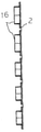
本発明はスライド土留板16に改良を加えるものであり、スライド土留板先端部に、後方へ向けて隙間塞ぎ用の鋼板2を取付けた。
The present invention is to improve the
この隙間塞ぎ用の鋼板2はその幅はスライド土留板16の幅よりも大きく、スライド土留板16の幅を拡幅するものであり、上下に隣接する隙間塞ぎ用の鋼板2同士は、スライド土留板16相互の隙間αとずれた箇所の隙間βで近接するようにした。
The width of the gap closing
すなわち、スライド土留板16相互の隙間αと間塞ぎ用の鋼板2相互の隙間βは上下にずれるものである。
That is, the gap α between the
なお、隙間塞ぎ用の鋼板2のスライド土留板16からの幅の張出しは、上下いずれか一方でもよい。
The width of the
また、スライド土留板先端部に、後方へ向けて隙間塞ぎ用の鋼板2を取付けに際しては、スライド土留板16の先端部はスライド土留め延長材5をボルト等で着脱自在に取付け、このスライド土留め延長材5に幅調整部材6を付設して、この幅調整部材6を介して隙間塞ぎ用の鋼板2を取付けた。
Further, when the
スライド土留め延長材5はスライド土留板16の先端部とほぼ同一形状の先端が鋭角のボックス体でよく、このスライド土留め延長材5をスライド土留板16の先端部に結合させることで、同時に隙間塞ぎ用の鋼板2を配置することができる。
The slide
なお、隙間塞ぎ用の鋼板2は幅調整部材6の厚さ分だけ外側に張り出して設けられ、幅調整部材6がスライド土留板16とオープンシールド機外面の外面を一致させ、これにより隙間塞ぎ用の鋼板2はスライド土留め延長材5から後方に伸びてオープンシールド機外面に当接する。
The
次に使用法について説明すると、ショベル等の掘削機7でオープンシールド機1の前面又は上面から土砂を掘削、かつ排土し、推進ジャッキ3を伸長してコンクリート函体4に反力をとって前進させるが、かかる掘進の際にはスライドジャッキ17によりスライド土留板16を前方に押し出す。
Next, the usage will be explained. Excavator 7 such as a shovel excavates and discharges earth and sand from the front surface or the upper surface of the
そして上下に隣接するスライド土留板16はその相互間に隙間は隙間塞ぎ用の鋼板2で塞がれているので、地下水と共に土砂が隙間から流入することはない。
Since the gaps between the
その結果、崩壊が生じるおそれも減少する。 As a result, the risk of collapse is also reduced.
また、スライドジャッキ17を縮めてスライド土留板16を戻す場合には隙間塞ぎ用の鋼板2もオープンシールド機1の側方後方に移動する。
Further, when the
1…オープンシールド機
2…塞ぎ用の鋼板
3…推進ジャッキ(シールドジャッキ)
4…コンクリート函体
5…スライド土留め延長材
6…幅調整部材
7…掘削機
8…発進坑
9…反力壁
16…スライド土留板
17…スライドジャッキ
22…フロント部
23…テール部
24…中折ジャッキ
29…隔壁
30…プレスバー(押角)
31…揚重機
35…裏込注入材
38…けん引ジャッキ
1 ...
4 ...
31 ... Lifting
Claims (3)
The open shield machine according to claim 1 or 2, wherein the steel plate for closing the gap is attached via a width adjusting member that matches the outer surface of the open shield machine and the outer surface of the slide retaining plate.
Priority Applications (1)
| Application Number | Priority Date | Filing Date | Title |
|---|---|---|---|
| JP2019110394A JP7025375B2 (en) | 2019-06-13 | 2019-06-13 | Open shield machine |
Applications Claiming Priority (1)
| Application Number | Priority Date | Filing Date | Title |
|---|---|---|---|
| JP2019110394A JP7025375B2 (en) | 2019-06-13 | 2019-06-13 | Open shield machine |
Publications (2)
| Publication Number | Publication Date |
|---|---|
| JP2020200735A JP2020200735A (en) | 2020-12-17 |
| JP7025375B2 true JP7025375B2 (en) | 2022-02-24 |
Family
ID=73742605
Family Applications (1)
| Application Number | Title | Priority Date | Filing Date |
|---|---|---|---|
| JP2019110394A Active JP7025375B2 (en) | 2019-06-13 | 2019-06-13 | Open shield machine |
Country Status (1)
| Country | Link |
|---|---|
| JP (1) | JP7025375B2 (en) |
Families Citing this family (1)
| Publication number | Priority date | Publication date | Assignee | Title |
|---|---|---|---|---|
| JP7384956B2 (en) | 2022-04-21 | 2023-11-21 | 誠 植村 | Open shield method and open shield machine |
Citations (1)
| Publication number | Priority date | Publication date | Assignee | Title |
|---|---|---|---|---|
| JP2006112100A (en) | 2004-10-14 | 2006-04-27 | Makoto Uemura | Open shield machine |
Family Cites Families (1)
| Publication number | Priority date | Publication date | Assignee | Title |
|---|---|---|---|---|
| JPS5020773B2 (en) * | 1971-12-28 | 1975-07-17 |
-
2019
- 2019-06-13 JP JP2019110394A patent/JP7025375B2/en active Active
Patent Citations (1)
| Publication number | Priority date | Publication date | Assignee | Title |
|---|---|---|---|---|
| JP2006112100A (en) | 2004-10-14 | 2006-04-27 | Makoto Uemura | Open shield machine |
Also Published As
| Publication number | Publication date |
|---|---|
| JP2020200735A (en) | 2020-12-17 |
Similar Documents
| Publication | Publication Date | Title |
|---|---|---|
| JP7025375B2 (en) | Open shield machine | |
| JP5155237B2 (en) | Open shield machine and open shield method using this open shield machine | |
| JP6629825B2 (en) | Road lining method in open shield method | |
| JP6034447B1 (en) | Open shield method | |
| JP6307136B2 (en) | Open shield method | |
| JP7061959B2 (en) | Open shield machine | |
| JP6947477B2 (en) | How to advance the open shield machine | |
| JP5491562B2 (en) | Open shield construction method for sand ground | |
| JP4520496B2 (en) | Open shield machine | |
| JP7384956B2 (en) | Open shield method and open shield machine | |
| JP4148047B2 (en) | Open shield machine | |
| JP3923973B2 (en) | Open shield machine | |
| JP5989863B1 (en) | Open shield machine | |
| JP4279441B2 (en) | Open shield machine and open shield method using this open shield machine | |
| JP5960787B2 (en) | Shield machine removal method in open shield method | |
| JP6989483B2 (en) | Open shield machine removal method | |
| JP2017014759A (en) | Open shield machine and box body installation construction method using the same | |
| JP3766423B2 (en) | Retaining wall construction method | |
| JP5389869B2 (en) | Open shield method | |
| JP5081858B2 (en) | Open shield machine | |
| JP3868959B2 (en) | Waterway construction method | |
| JP2657716B2 (en) | Water stop device of open shield machine | |
| JP5639213B2 (en) | Open shield method | |
| JP6989538B2 (en) | Open shield machine | |
| JP6764438B2 (en) | Open shield method with propulsion method |
Legal Events
| Date | Code | Title | Description |
|---|---|---|---|
| A621 | Written request for application examination |
Free format text: JAPANESE INTERMEDIATE CODE: A621 Effective date: 20200917 |
|
| A977 | Report on retrieval |
Free format text: JAPANESE INTERMEDIATE CODE: A971007 Effective date: 20210806 |
|
| A131 | Notification of reasons for refusal |
Free format text: JAPANESE INTERMEDIATE CODE: A131 Effective date: 20210907 |
|
| A521 | Request for written amendment filed |
Free format text: JAPANESE INTERMEDIATE CODE: A523 Effective date: 20211022 |
|
| TRDD | Decision of grant or rejection written | ||
| A01 | Written decision to grant a patent or to grant a registration (utility model) |
Free format text: JAPANESE INTERMEDIATE CODE: A01 Effective date: 20220208 |
|
| A61 | First payment of annual fees (during grant procedure) |
Free format text: JAPANESE INTERMEDIATE CODE: A61 Effective date: 20220210 |
|
| R150 | Certificate of patent or registration of utility model |
Ref document number: 7025375 Country of ref document: JP Free format text: JAPANESE INTERMEDIATE CODE: R150 |